

Page 1
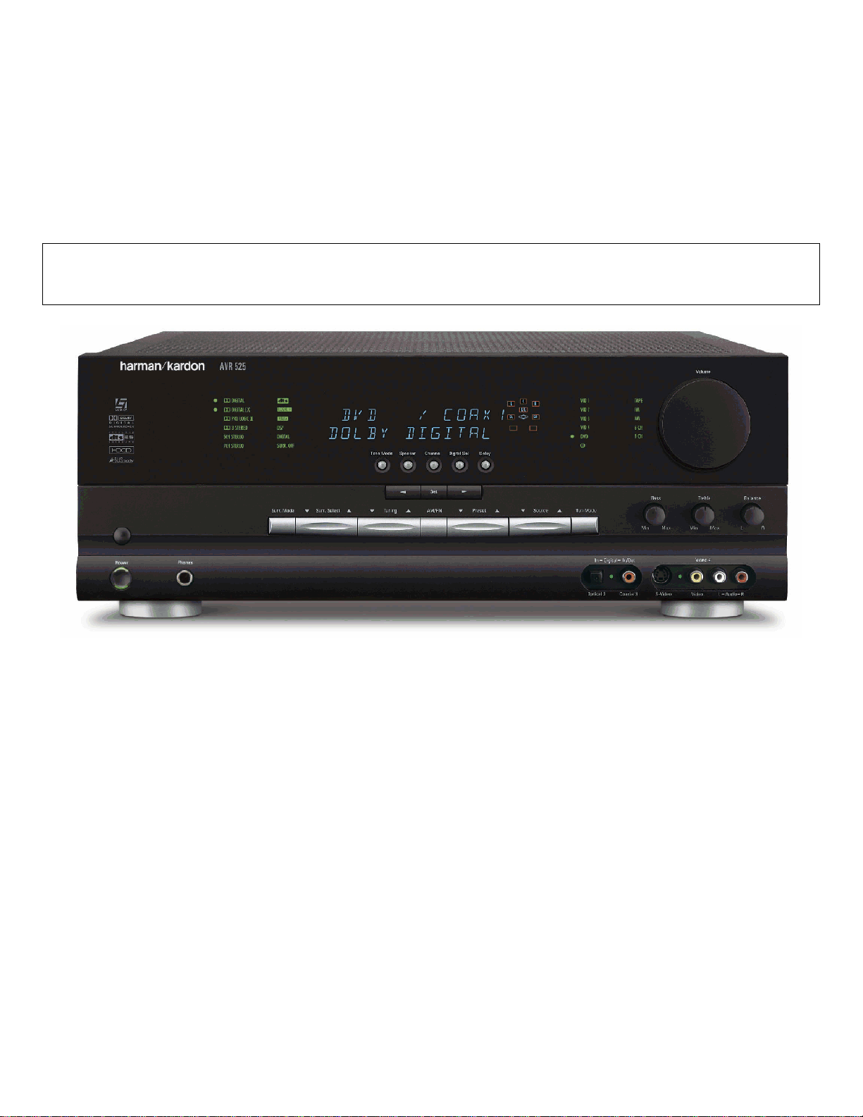
harman/kardon
AVR525
A/V DOLBY DIGITAL RECEI VER
SERVICE MANUAL
ESD W ARNING………………………….…….2
LEAKAGE TESTING……………….....……....3
BASIC SPECIFICATIONS…………….….…..4
FRONT PANEL CONTROLS………………...5
FRONT PANEL DISPLAY…………………….7
REAR PANEL CONNECTIONS……..….……8
REMOTE CONTROL FUNCTIONS…….…..11
INSTALLATION AND CONNECTIONS…....14
TROUB L E S HO O T ING G UID E...................17
PROCESSOR RESET………..……….…….17
BLOCK DIAGRAM……………………..…….18
AMPLIFIER BIAS ADJUSTMENT……...…..19
harman/kardon, Inc.
250 Crossways Park Dr.
CONTENTS
SERVICE BULLETIN # H/K2003-05….…..24
SERVICE BULLETIN # H/K2004-04……...25
TECH TIP HKTT2003-01………….……….28
TECH TIP HKTT2004-03………….……….29
EXPLODED VIEW………………………….33
EXPLODED VIEW PARTS LIST………….34
ELECTRICAL PARTS LIST………..…..….36
PCB DRAWINGS………………..….………92
SEMICONDUCTOR PINOUTS……..….…104
SCHEMATICS………………….…..………167
WIRING DIAGRAM..………………..….….186
PACKAGE………………………………..…187
Woodbury, New York 11797 Rev2 8/2005
Page 2
AVR525 harman/kardon
2
Some semiconductor (solid state) devices can be damaged easily by static electricity. Such components commonly are called
Electrostatically Sensitive (ES) Devices. Examples of typical ES devices are integrated circuits and some field effect transistors and
semiconductor "chip" components.
The following techniques should be used to help reduce the incidence of component damage caused by static electricity.
1. Immediately before handling any semiconductor component or semiconductor-equipped assembly, drain off any electrostatic charge on
your body by touching a known earth ground. Alternatively, obtain and wear a commercially available discharging wrist strap device,
which should be removed for potential shock reasons prior to applying power to the unit under test.
2. After removing an electrical assembly equipped with ES devices, place the assembly on a conductive surface such as aluminum foil, to
prevent electrostatic charge build-up or exposure of the assembly.
3. Use only a grounded-tip soldering iron to solder or unsolder ES devices.
4. Use only an anti-static solder removal device. Some solder removal devices not classified as "anti-static" can generate electrical charges
sufficient to damage ES devices.
5. Do not use freon-propelled chemicals. These can generate electrical change sufficient to damage ES devices.
6. Do not remove a replacement ES device from its protective package until immediately before you are ready to install it. (Most replacement
ES devices are packaged with leads electrically shorted together by conductive foam, aluminum foil or comparable conductive material.)
7. Immediately before removing the protective material from the leads of a replacement ES device, touch the protective material to the
chassis or circuit assembly into which the device will be installed.
CAUTION :
8. Minimize bodily motions when handling unpackaged replacement ES devices. (Otherwise harmless motion such as the brushing together
or your clothes fabric or the lifting of your foot from a carpeted floor can generate static electricity sufficient to damage an ES devices.
Be sure no power is applied to the chassis or circuit, and observe all other safety precautions.
Each precaution in this manual should be followed during servicing.
Components identified with the IEC symbol in the parts list are special significance to safety. When replacing a component identified with
, use only the replacement parts designated, or parts with the same ratings or resistance, wattage, or voltage that are designated in the
parts list in this manual. Leakage-current or resistance measurements must be made to determine that exposed parts are acceptably
insulated from the supply circuit before retuming the product to the customer.
Page 3
AVR525 harman/kardon
3
Before returning the unit to the user, perform the following safety checks :
1. Inspect all lead dress to make certain that
leads are not pinched or that hardware is not
lodged between the chassis and other metal
parts in the unit.
2. Be sure that any protective devices such as
nonmetallic control knobs, insulating fish-
papers, cabinet backs, adjustment and
compartment covers or shields, isolation
resistor-capacity networks, mechanical
insulators, etc. Which were removed for the
servicing are properly re-installed.
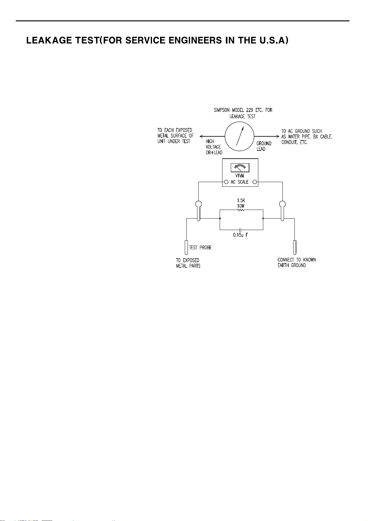
3. Be sure that no shock hazard exists ; check for leakage
current usingSimpson Model 229 Leakage Tester, standard
equipment item No. 21641, RCA Model WT540A or use
alternate method as follows : Plug the power cord directly
Into a 120 volt AC receptacle (do not use an Isolation
Transformer for this test). Using two clip leads, connect a
1500 ohms,10watt Resistor paralleledby a 0.15uFcapacitor,in series withall exposed metalcabinet parts anda known earthground, such
as a water pipe or conduit. Use a VTVM or VOM with 1000 ohms per volt, or higher sensitivity to measure the AC voltage drop across the
resistor. (See diagram) Move the resistor connection to each exposed metal part having a return path to the chassis (antenna, metal,
cabinet, screwheads, knobsand controlshafts, escutcheon, etc.) and measure theAC voltagedrop across the resistor. (This test shouldbe
performed withthe 0.35 volt RMS or more is excessiveand indicates apotential shock hazard which must be corrected beforereturning the
unit to the owner.
Page 4

4
AVR 525 TECHNICAL SPECIFICATIONS
Audio Section
Stereo Mode
Continuous Average Power (FTC)
85 Watts per channel,20Hz–20kHz,
@ <0.07% THD,both channels driven into 8 ohms
Seven-Channel Surround Modes
Power per Individual Channel
Front L&R channels:
70 Watts per channel
@ <0.07% THD,20Hz–20kHz into 8 ohms
Center channel:
70 Watts @ <0.07% THD, 20Hz–20kHz into 8 ohms
Surround (L & R Side, L & R back) channels:
70 Watts per channel
@ <0.07% THD,20Hz–20kHz into 8 ohms
Input Sensitivity/Impedance
Linear (High-Level) 200mV/47k ohms
Signal-to-Noise Ratio (IHF-A) 95dB
Surround System Adjacent Channel Separation
Pro Logic I/II 40dB
Dolby Digital (AC-3) 55dB
DTS 55dB
Frequency Response
@ 1W (+0dB,–3dB) 10Hz –100kHz
High Instantaneous
Current Capability (HCC) ±45 Amps
Transient Intermodulation
Distortion (TIM) Unmeasurable
Slew Rate 40V/µsec
FM Tuner Section
Frequency Range 87.5 –108.0MHz
Usable Sensitivity IHF 1.3µV/ 13.2dBf
Signal-to-Noise Ratio Mono/Stereo 70/68dB
Distortion Mono/Stereo 0.2/0.3%
Stereo Separation 40dB @ 1kHz
Selectivity ±400kHz, 70dB
Image Rejection 80dB
IF Rejection 90dB
AM Tuner Section
Frequency Range 525–1710kHz
Signal-to-Noise Ratio 45dB
Usable Sensitivity Loop 500 µV
Distortion 1kHz, 50% Mod 0.8%
Selectivity ±10kHz, 30dB
Video Section
Television Format NTSC
Input Level/Impedance 1Vp-p /75 ohms
Output Level/Impedance 1Vp-p /75 ohms
Video Frequency Response
(Composite and S-Video) 10Hz–8MHz (–3dB)
Video Frequency Response
(Component Video) 10Hz–50MHz (–3dB)
General
Power Requirement AC 120V/60Hz
Power Consumption 120W idle,1040W maximum
(7 channels driven)
Dimensions Width 17.3 inches (440mm)
Height 6.5 inches (165mm)
Depth 17.1 inches (435mm)
Weight 44 lb (20kg)
Depth measurement includes knobs,buttons and ter minal connections.
Height measurement includes feet and chassis.
All features and specifications are subject to change without notice.
Harman Kardon and Power for the Digital Revolution are registered trademarks of
Harman International Industries,Incorporated.
is a trademark of Harman International Industries,Incorporated (patent no.5,386,478).
*Manufactured under license from Dolby Laboratories.“Dolby,”“Pro Logic,”“Pro Logic II” and the
Double-D symbol are trademarks of Dolby Laboratories.Confidential Unpublished Works.
©1992–1999 Dolby Laboratories,Inc.All rights reserved.
DTS,DTS Surround, DTS-ES and DTS Neo:6 are registered trademarks of Digital Theater Systems, Inc.
UltraStereo is a trademark of UltraStereo Corp.
VMAx is a registered trademark of Harman International Industries,Incorporated, and is an
implementation of Cooper Bauck Transaural Stereo under patent license.
Logic 7 is a registered trademark of Harman International Industries,Incorporated.
HDCD system manufactured under license from Pacific Microsonics,Inc.This product is
covered by one or more of the following: in the USA: 5,479,168;5,638,074; 5,640,161;5,808,574;
5,838,274; 5,854,600; 5,864,311; 5,872,531; and in Australia: 669114. Other patents pending.
A-BUS and A-BUS Ready are registered trademarks of Leisure Tech Electronics Pty Ltd Australia.
AVR525 harman/kardon
4
TM
Page 5
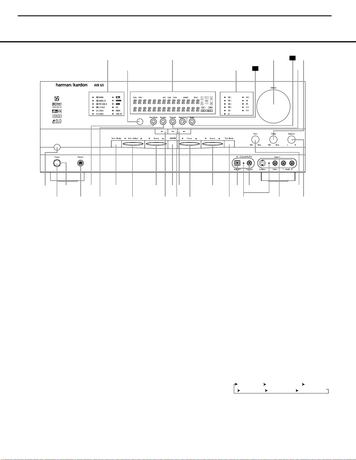
FRONT-PANEL CONTROLS
1 Main Power Switch: Press this button to apply
power to the AVR 525.When the switch is pressed
in, the unit is placed in a Standby mode, as indicated
by the amber Power Indicator 3 surrounding the
System Power Control 2. This button MUST be
pressed in to operate the unit.To turn the unit off and
prevent the use of the remote control, this switch
should be pressed until it pops out from the front
panel so that the word “OFF”may be read at the top
of the switch.
NOTE: This switch is normally left in the “ON” position.
2 System Power Control: When the Main Power
Switch1is “ON,” press this button to turn on the
AVR 525;press it again to turn the unit off.Note that
the Power Indicator3surrounding the switch will
turn green when the unit is on.
3 Power Indicator: This LED will be lit in amber
when the unit is in the Standby mode to signal that the
unit is ready to be turned on.When the unit is in operation, the indicator will turn green.
4 Headphone Jack:This jack may be used to listen
to the AVR 525’s output through a pair of headphones.
Be certain that the headphones have a standard
1
/4"
stereo phone plug.The main room speakers will
automatically be turned off when the headphone jack
is in use.
5 Tone Mode:This button controls the tone control
settings,enabling adjustment of the bass and treble
boost/cut or the removal of the tone controls from the
signal path.The first press of the button displays a
TONE IN message in the Main Information
Display ˜.
If you wish to set the tone controls to “flat,”
without any treble or bass alteration, press the
‹
or
›
Selector Buttons )# so that TONE OUT
appears in the Lower Display Line B.
6 Speaker Selector: Press this button to begin the
process of configuring the AVR 525 for the type of
speakers it is being used with. For complete information on configuring the speaker settings using the
front-panel controls see page 23.
7 Surround Mode Group Selector: Press this but-
ton to select the top-level group of surround modes.
Each press of the button will select a major mode
grouping in the following order:
Dolby Modes DTS Digital Modes VMAx Modes
DSP Modes Stereo Modes Logic 7 Modes
B
Once the button is pressed so that the name of the
desired surround mode group appears in the on-screen
display and in the Lower Display Line B, press the
1 Main Power Switch
2 System Power Control
3 Power Indicator
4 Headphone Jack
5 Tone Mode
6 Speaker Selector
7 Surround Mode Group Selector
8 Surround Mode Selector
9 Tuning Selector
)
‹
Button
! Tuner Band Selector
@ Set Button
#
›
Button
$ Preset Station Selector
% Input Source Selector
^ TunerMode Selector
& Optical 3 Digital Input
* Input/Output Status Indicator
( Coaxial 3 Digital Input/Output
Ó Video 4 Input/Output Jacks
Ô Bass Control
Balance Control
Ò Treble Control
Ú Channel Adjust Selector
Û Delay Adjust Selector
Ù Digital Input Selector
ı Volume Control
ˆ Input Indicators
˜ Main Information Display
¯ Remote Sensor Window
˘ Surround Mode Indicators
2
4
5
6
7
9
!
@
#
%
&
*
Ó
Ô
(
25
1
3
8 ) $
^
Ú
˘
˜
ˆ
¯
Ò
26
ı
FRONT-PANEL CONTROLS
5
AVR525 harman/kardon
5
Dolby Modes _ DTS Digital Modes _ VMAx Modes
_
DSP Modes _ Stereo Modes _ Logic 7 Modes
Page 6

Surround Mode Selector 8 to cycle through the
individual modes available.For example,press this button to select Dolby modes, and then press the
Surround Mode Selector 8 to choose from the various mode options.
8 Surround Mode Selector: Press this button
to select from among the available surround mode
options for the major mode group selected.The
specific modes will vary based on the number of
speakers available,the major mode group and
whether the input source is digital or analog.For
example,press the Surround Mode Group Selector
7 to select a major mode grouping such as Dolby or
Logic 7, and then press this button to see the specific
mode choices that are available.For more information
on mode selection, see page 28.
9 Tuning Selector: Press the left side of the button
to tune lower-frequency stations and the right side of
the button to tune higher-frequency stations.When a
station with a strong signal is reached, the TUNED
Indicator I will be lit in the Main Information
Display ˜.
)‹Button: When making system configuration
changes using the front-panel controls,press this button to scroll left through the available choices for the
option being adjusted.
! Tuner Band Selector:Pressing this button will
automatically switch the AVR525 to the Tuner mode.
Pressing it again will switch between the AM and FM
frequency bands.(See page 31 for more information
on the tuner.)
@ Set Button: When making system configuration
changes using the front-panel controls,press this button to enter a setting into the unit’s memory.
#
› Button: When making system configuration
changes using the front-panel controls,press this button to scroll right through the available choices for the
option being adjusted.
$ Preset Station Selector: Press this button to
scroll up or down through the list of stations that have
been entered into the preset memory.(See pages 31
and 32 for more information on tuner programming.)
% Input Source Selector: Press this button to
change the input by scrolling up or down through the
list of input sources.
^ Tuner Mode Selector: Press this button to select
Auto or Manual tuning.When the button is pressed so
that the AUTO Indicator J lights,the tuner will search
for the next station with an acceptable signal when the
Tuning Selector9u
é
is pressed.When the
button is pressed so that the AUTO Indicator J is not
lit, each press of the Tuning Selector 9u
é
will
increase the frequency.(See page 31 for more informa-
tion on using the tuner.) This button may also be used
to switch between Stereo and Mono modes for FM
radio reception.When weak reception is encountered,
press the button until the Stereo Indicator H goes
out to switch to Mono reception. Press and hold again
to switch back to Stereo mode.(See page 31 for more
information on using the tuner.)
& Optical 3 Digital Input: Connect the optical digital
output of an audio or video product to this jack.
* Input/Output Status Indicator: This LED indicator
will normally light green to show that the front-panel
Video 4 Input/Output Jacks Ó are operating as
inputs.When these jacks are configured for use as an
output, the indicator will turn red to show that the jack
may be used for recording.(See page 32 for more
information on configuring the front-panel jacks as outputs,rather than inputs.)
( Coaxial 3 Digital Input/Output: Connect the
coaxial digital input or output for a digital audio product such as a portable audio player or video game to
this jack.The jack is normally an input, but may be
switched to an output for recording using the menu
system. See page 32 for more information.
Ó Video 4 Input/Output Jacks: These audio/video
jacks may be used for temporary connection to video
games or portable audio/video products such as camcorders and portable audio players.
Ô Bass Control: Use this control to boost or reduce
the low-frequency output of the left/right front channels by as much as ±10dB.Set this control as you
find suitable to adjust to your specific taste or room
acoustics.
Balance Control: Use this control to change the
relative volume for the front left/right channels.
NOTE: When multichannel surround modes are in use,
this control should be at the midpoint, or “12 o’clock”
position for proper operation.
Ò Treble Control:Use this control to boost or
reduce the high-frequency output of the left/right front
channels by as much as ±10dB.Set this control as
you find suitable to adjust to your specific taste or
room acoustics.
Ú Channel Adjust Selector: Press the button to
begin the process of adjusting the channel level outputs using the source currently playing through your
AVR.For complete information on adjusting the channel output level, see page 37.
Û Delay Adjust Selector: Press this button to
begin the process of adjusting the delay settings for
Dolby surround modes.See page 23 for more information on delay adjustments.
Ù Digital Input Selector: Press this button to begin
the process of selecting a digital source for use with
the currently selected input. Once the button has been
pressed, use the ‹ or › Buttons )# to choose
the desired input and then press the Set Button @
to enter the setting into the unit’s memory.See page
30 for more information on digital audio.
ı Volume Control: Turn this knob clockwise to
increase the volume,counterclockwise to decrease the
volume.If the AVR 525 is muted,adjusting volume
control will automatically release the unit from the
silenced condition.
ˆ Input Indicators: A green LED will light to the left
of the input that is currently the input source for the
AVR 525.
˜ Main Information Display: This display delivers
messages and status indications to help you operate
the receiver. (See page 7 for a complete explanation
of the Information Display.)
¯ Remote Sensor Window:The sensor behind
this window receives infrared signals from the remote
control.Aim the remote at this area and do not block
or cover it unless an external remote sensor is
installed.
˘ Surround Mode Indicators: These LEDS will
light to show the surround mode and digital bitstream
in use.Note that depending on the specific combination of input sources and surround mode selected,
more than one indicator may light. (See page 28 for
more information.)
FRONT-PANEL CONTROLS
6
AVR525 harman/kardon
6
Page 7
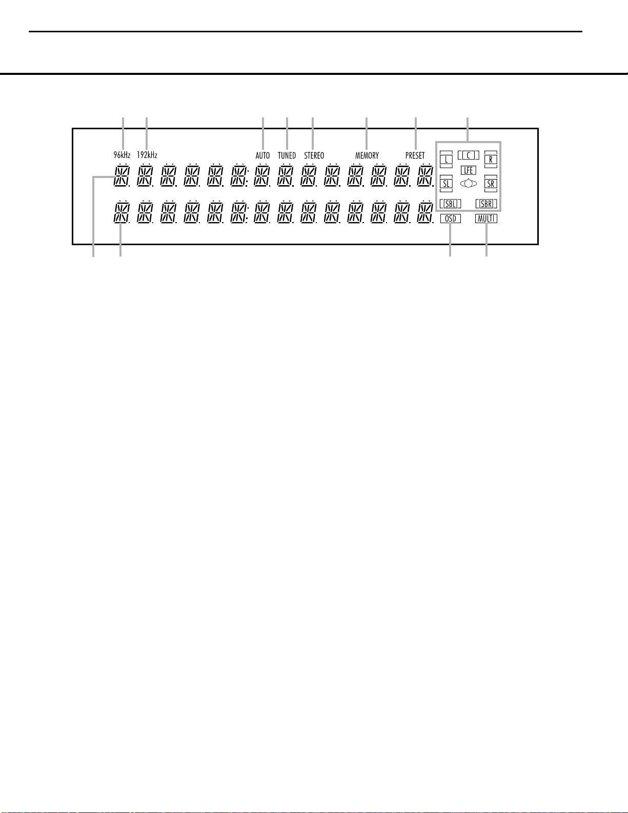
FRONT-PANEL INFORMATION DISPLAY
7
B
C
E
F
G
H
IJ
K
L
A
D
A Upper Display Line
B Lower Display Line
C OSD Indicator
D Multiroom Indicator
E Speaker/Channel Input Indicators
F PRESET Indicator
G MEMORY Indicator
H STEREO Indicator
I TUNED Indicator
J AUTO Indicator
K 192kHz Indicator
L 96kHz Indicator
A Upper Display Line: Depending on the unit’s status,
a variety of messages will appear here.In normal operation,the current audio and video input source information
will appear on this line.
B Lower Display Line: Depending on the unit’s
status,a variety of messages will appear here.In normal operation, the current surround mode name will
appear on this line.
C OSD Indicator: When the OSD system is in use,
this indicator lights to remind you that the other indicators in this display do not function when the OnScreen Display is being used.
D Multiroom Indicator: This indicator lights when
the multiroom system is active.It will remain lit when
the multiroom system is in use even though the main
room system is in the Standby mode and all other
indicators are dark. (See page 36 for more information on the Multiroom system.)
E Speaker/Channel Input Indicators: These indica-
tors are multipurpose,indicating either the speaker type
selected for each channel or the incoming data-signal
configuration.The left, center,right, right surround and
left surround speaker indicators are composed of three
boxes,while the subwoofer is a single box.The center
box lights when a “Small”speaker is selected,and the
two outer boxes light when “Large”speakers are selected.
When none of the boxes are lit for the center, surround
or
subwoofer channels,no speaker has been selected for
one of those positions.(See page 21 for more informa-
tion on speaker setup.) The letters inside each of the
center boxes display the active input channels.For standard analog inputs,only the L and R will light,indicating a
stereo input.When a digital source is playing,the indicators
will light to display the channels being received at the
digital input.When the letters flash, the digital input has
been interrupted. (See page 30 for more information on
the Channel Indicators.)
F PRESET Indicator: This indicator lights when the
tuner is in use to show that the present number for the
current station being listened to appears in the Upper
Display Line.(See page 31 for more information on
tuner presets.)
G MEMORY Indicator: This indicator flashes when
entering presets and other information into the tuner’s
memory.
H STEREO Indicator: This indicator lights when an
FM station is being tuned in stereo.
I
TUNED Indicator:
This indicator lights when a station is being received with sufficient signal strength to
provide acceptable listening quality.
J AUTO Indicator: This indicator lights when the
tuner’s Auto mode is in use.
K 192kHz Indicator: This indicator lights when the
input source has a 192kHz bit rate.
L 96kHz Indicator: This indicator lights when the
input source has a 96kHz bit rate.
AVR525 harman/kardon
7
Page 8
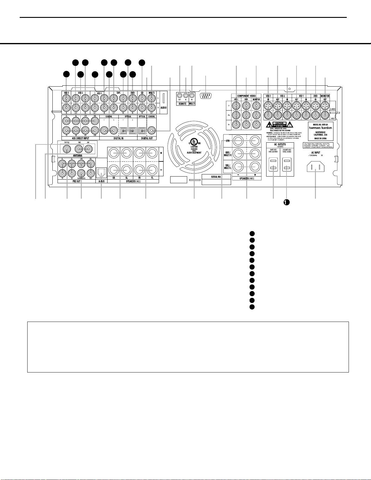
REAR-PANEL CONNECTIONS
¡ AM Antenna
™ FM Antenna
£ Preamp Outputs
¢ Subwoofer Output
∞ A-BUS Connector
§ Surround Speaker Outputs
¶ Front Speaker Outputs
• Fan Vents
ª Center Speaker Outputs
‚ Surround Back/Multiroom Speaker Outputs
⁄ Switched AC Accessory Outlet
¤ Unswitched AC Accessory Outlet
‹ AC Power Cord Jack
› Video Monitor Outputs
fi DVD Video Inputs
fl Video 1 Video Inputs
‡ Video 1 Video Outputs
° Video 2 Video Inputs
· Video 2 Video Outputs
a Video 3 Video Inputs
b Component Video Monitor Outputs
c DVD Component Video Inputs
d Video 2 Component Video Inputs
e RS-232 Port
f Multiroom IR Input
g Remote IR Input
h Remote IR Output
i Coaxial Digital Audio Output
j Multiroom Audio Outputs
k Optical Digital Audio Output
CD Audio Inputs
DVD Audio Inputs
Optical Digital Audio Inputs
Tape Inputs
Tape Outputs
Coaxial Digital Audio Inputs
Video 1 Audio Inputs
Video 1 Audio Outputs
Video 2 Audio Inputs
8-Channel Direct Inputs
Video 2 Audio Outputs
Video 3 Audio Inputs
¡ AM Antenna: Connect the AM loop antenna sup-
plied with the receiver to these terminals.If an external
AM antenna is used, make connections to the AM and
GND terminals in accordance with the instructions supplied with the antenna.
™ FM Antenna: Connect the supplied indoor or an
optional external FM antenna to this terminal.
£ Preamp Outputs: Connect these jacks to an
optional, external power amplifier for applications
where higher power is desired.
¢ Subwoofer Output: Connect this jack to the line-
level input of a powered subwoofer. If an external subwoofer amplifier is used, connect this jack to the subwoofer amplifier input.
∞ A-BUS Connector:
Connect this jack to an optional
A-BUS-certified remote room keypad or amplifier to
extend the multiroom capabilities of your AVR 525.
See page 36 for more information on A-BUS.
§ Surround Speaker Outputs: Connect these out-
puts to the matching + and – terminals on your surround channel speakers.In conformance with the new
CEA color-code specification, the blue terminal is the
NOTE:To assist in making the correct connections for
multichannel input, output and speaker connections,
all connection jacks and terminals are color-coded
in conformance with the latest CEA standards as
follows:
Front Left: White
Front Right: Red
Center: Green
Surround Left: Blue
Surround Right: Gray
Surround Back Left: Brown
Surround Back Right: Tan
Subwoofer: Purple
Digital Audio: Orange
Composite Video: Yellow
Component Video “Y”: Green
Component Video “Pr”: Red
Component Video “Pb”: Blue
REAR-PANEL CONNECTIONS
8
AVR525 harman/kardon
8
33
41
39
37
35
31
j
hgf
d
b
·
‡
fi
42
40
¡
™
£
¢∞§ ¶
38
36
32
34
k
i
•
e
ª
a
‚
31
32
33
34
35
36
37
38
39
40
41
42
⁄
°c
2
fl
›
‹
Page 9

9
REAR-PANEL CONNECTIONS
positive,or “+” terminal that should be connected to
the red (+) terminal on the Surround Left speaker with
older color-coding,while the gray terminal should be
connected to the red (+) terminal on the Surround
Right speaker with the older color-coding.Connect the
black (–) terminal on the AVR to the matching black
negative (–) terminals for each surround speaker. (See
page 15 for more information on speaker polarity.)
¶ Front Speaker Outputs: Connect these outputs
to the matching + or – terminals on your left and right
speakers.When making speaker connections always
make certain to maintain correct polarity by connecting
the color-coded (white for front left and red for front
right) (+) terminals on the AVR525 to the red (+)
terminals on the speakers and the black (–) terminals
on the AVR525 to the black (–) terminals on the
speakers.See page 15 for more information on
speaker polarity.
• Fan Vents:These ventilation holes are the output
of the AVR 525’s airflow system.To ensure proper
operation of the unit and to avoid possible damage to
delicate surfaces,make certain that these holes are
not blocked and that there is at least three inches of
open space between the vent holes and any wooden
or fabric surface.
ª Center Speaker Outputs: Connect these outputs
to the matching + and – terminals on your center
channel speaker. In conformance with the new CEA
color-code specification, the green terminal is the
positive,or “+” terminal that should be connected to
the red (+) terminal on speakers with the older colorcoding.Connect the black (–) terminal on the AVR to
the black negative (–) terminal on your speaker. (See
page 15 for more information on speaker polarity.)
‚ Surround Back/Multiroom Speaker Outputs:
These speaker terminals are normally used to power
the surround back left/surround back right speakers
in a 7.1 channel system. However,they may also be
used to power the speakers in a second zone,which
will receive the output selected for a multiroom system.
To change the output fed to these terminals from
the default of the Surround Back speakers to the
Multiroom Output, you must change a setting in the
Advanced Menu of the OSD system. See page 34 for
more information on configuring this speaker output. In
normal surround system use,the brown and black terminals are the surround back left channel positive (+)
and negative (–) connections and the tan and black
terminals are the surround back right positive (+) and
negative (–) terminals.For multiroom use,connect the
brown and black SBL terminals to the red and black
connections on the left remote zone speaker and connect the tan and black SBR terminals to the red and
black terminals on the right remote zone speaker.
⁄ Switched AC Accessory Outlet: These outlets
may be used to power any device you wish to have
turned on when the AVR525 is turned on with the
System Power Control Button 2.
¤ Unswitched AC Accessory Outlet: This outlet
may be used to power any AC device.The power will
remain on at this outlet regardless of whether the
AVR525 is on or off.
NOTE: The total power consumption of all devices
connected to the accessory outlets should not exceed
100 watts.
‹ AC Power Cord Jack: Connect the AC power
cord to this jack when the installation is complete.
To ensure safe operation, use only the power cord
supplied with the unit. If a replacement is required it
must be of the same type and capacity.
› Video Monitor Outputs: Connect these jacks to
the composite or S-Video input of a TV monitor or
video projector to view the on-screen menus and the
output of any standard video source selected by the
receiver’s video switcher.
fi DVD Video Inputs: Connect the composite or S-
Video outputs of a DVD player or other video source
to these jacks.
fl Video 1 Video Inputs: Connect the composite or
S-Video PLAY/OUT jacks of a VCR or other video
source to these jacks.
‡ Video 1 Video Outputs: Connect the composite
or S-Video REC/IN jacks of a VCR or other video
recording device such as a DVD recorder or PVR to
these jacks.
° Video 2 Video Inputs: Connect the composite or
S-Video PLAY/OUT jacks of a VCR or other video
source to these jacks.
· Video 2 Video Outputs: Connect the composite
or S-Video REC/IN jacks of a VCR or other video
recording device such as a DVD recorder or PVR to
these jacks.
a Video 3 Video Inputs: Connect the composite or
S-Video PLAY/OUT jacks of a VCR or other video
source to these jacks.
b Component Video Monitor Outputs: Connect
these outputs to the component video inputs of a
video projector or monitor.When a source connected
to one of the Component Video Inputs cd is
selected the signal will be sent to these jacks.
c DVD Component Video Inputs:Connect the
Y/Pr/Pb component video outputs of a DVD player to
these jacks.
d Video 2 Component Video Inputs: Connect the
Y/Pr/Pb component video outputs of an HDTV Set-top
convertor, satellite receiver or other video source
device with component video outputs to these jacks.
e RS-232 Port: This jack is used to enable the
AVR525 to be controlled by an external computer
or programmable remote system that uses RS-232
commands.Due to the complexity of RS-232 connections,we recommend that they be made by a
trained and qualified custom installer. See page 16
for more information on the RS-232 control port.
f Multiroom IR Input: Connect the output of an IR
sensor in a remote room to this jack to operate the
AVR 525’s multiroom control system.
g Remote IR Input: If the AVR 525’s front-panel
IR sensor is blocked due to cabinet doors or other
obstructions,an external IR sensor may be used.
Connect the output of the sensor to this jack.
h Remote IR Output: This connection per mits the
IR sensor in the receiver to serve other remote controlled devices.Connect this jack to the “IR IN”jack on
Harman Kardon (or other compatible) equipment.
i Coaxial Digital Audio Output: Connect this jack
to the coaxial digital input of a CD-R/RW, MiniDisc or
other digital recorder.
j Multiroom Audio Outputs: Connect these jacks
to the optional external audio power amplifier and
video distribution system that delivers the source
selected for multizone distribution.
k Optical Digital Audio Output: Connect this jack
to the optical digital input connector on a CD-R/RW,
MiniDisc or other digital recorder.
CD Audio Inputs: Connect these jacks to the
analog audio output of a compact disc player or CD
changer.
DVD Audio Inputs: Connect the left/right analog
outputs of a DVD player or other audio source to
these jacks.
Optical Digital Audio Inputs: Connect the optical digital output from a DVD player, HDTV receiver,
the S/P-DIF output of a compatible computer sound
card playing MP3 files or streams,LD player or CD
player to these jacks.The signal may be a Dolby Digital
signal, a DTS signal or a standard PCM digital source.
Tape Inputs:Connect these jacks to the PLAY/OUT
jacks of an audio recorder.
Tape Outputs:Connect these jacks to the
RECORD/INPUT jacks of an audio recorder.
AVR525 harman/kardon
9
31
32
33
34
35
Page 10

Coaxial Digital Audio Inputs: Connect the coax
digital output from a DVD player,HDTV receiver,the
S/P-DIF output of a compatible computer
sound card
playing MP3 files or streams,LD player
or CD player to
these jacks.The signal may be a Dolby Digital signal,
DTS signal or a standard PCM digital source.Do not
connect the RF digital output of an LD player to
these jacks.
Video 1 Audio Inputs: Connect the left/right
PLAY/OUT audio output jacks on a VCR or other video
source to these jacks.
Video 1 Audio Outputs: Connect the left/right
REC/IN audio input jacks on a VCR or other video
source to these jacks.
Video 2 Audio Inputs: Connect the left/right
PLAY/OUT audio output jacks on a VCR or other video
source to these jacks.
8-Channel Direct Inputs: These jacks are used
for connection to source devices such as DVD-Audio
or SACD players with discrete analog outputs.
Depending on the source device in use,all eight jacks
may be used, though in many cases only connections
to the front left/right, center,surround left/right and
LFE (subwoofer input) jacks will be used for standard
5.1 audio signals.
Video 2 Audio Outputs: Connect the left/right
REC/IN audio input jacks on a VCR or other video
source to these jacks.
Video 3 Audio Inputs: Connect the left/right
PLAY/OUT audio output jacks on a VCR, PVR, cable
set-top,satellite receiver, HDTV receiver or other video
source to these jacks.
REAR-PANEL CONNECTIONS
10
AVR525 harman/kardon
10
36
37
38
39
40
41
42
Page 11
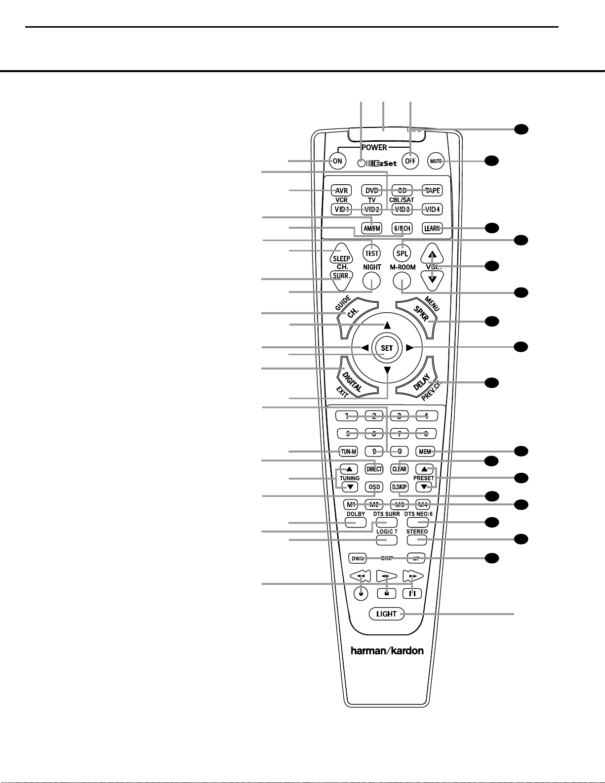
MAIN REMOTE CONTROL FUNCTIONS
11
●
●
●
●
●
●
●
●
●
●
●
●
●
●
●
●
●
a Power Off Button
b IR Transmitter Window
c Program/SPL Indicator
d Power On Button
e Input Selectors
f AVR Selector
g AM/FM Tuner Select
h 6-Channel/8-Channel Direct Input
i Test Button
j Sleep Button
k Surround Mode Selector
l Night Mode
m Channel Select Button
n
⁄/¤
Buttons
o
‹
Button
p Set Button
q Digital Select
r Numeric Keys
s Tuner Mode
t Direct Button
u Tuning Up/Down
v OSD Button
w Dolby Mode Select Button
x DTS Digital Mode Selector
y Logic 7 Mode Select Button
z Transport Controls
`
Light Button
28
Skip Up/Down Buttons
29
Stereo Mode Select Button
30
DTS Neo:6 Mode Select
31
Macro Buttons
32
Disc Skip Button
33
Preset Up/Down
34
Clear Button
35
Memory Button
36
Delay/Prev.Ch.
37
›
Button
38
Speaker Select
39
Multiroom
40
Volume Up/Down
41
SPL Selector
42 Learn Button
43
Mute
44
EzSet Sensor Microphone
NOTE: The function names shown here are each button’s feature when used with the AVR525. Most buttons have additional functions when used with other devices.See pages
42–43 for a list of these functions.
AVR 525
a
bc
d
e
g
h
i
j
l
n
o
`
32
30
29
37
36
35
34
33
31
38
z
x
39
40
41
42
43
44
f
m
k
p
q
n
r
s
t
u
v
w
y
28
AVR525 harman/kardon
11
Page 12
12
MAIN REMOTE CONTROL FUNCTIONS
IMPORTANT NOTE:The AVR 525’s remote may be
programmed to control up to eight devices,including
the AVR 525.Before using the remote, it is important to
remember to press the Input Selector Button e
that corresponds to the unit you wish to operate.
In addition, the AVR 525’s remote is shipped from
the factory to operate the AVR 525and most
Harman Kardon CD or DVD players and cassette
decks.The remote is also capable of operating a
wide variety of other products using the control codes
that are part of the remote.Before using the remote
with other products,follow the instructions on pages
44–53 to program the proper codes for the products
in your system.
It is also important to remember that many of the buttons on the remote take on different functions,depending on the product selected using the Device Control
Selectors.The descriptions shown here primarily detail
the functions of the remote when it is used to operate
the AVR 525.(See page 40 for infor mation about
alternate functions for the remote’s buttons.)
a Power Off Button: Press this button to place the
AVR525 or a selected device in the Standby mode.
Note that this will turn off the main room functions,but if
the Multiroom system is activated, it will continue to
function.
b IR Transmitter Window:Point this window
towards the AVR 525 when pressing buttons on the
remote to make certain that infrared commands are
properly received.
c Program/SPL Indicator: This three-color indica-
tor is used to guide you through the process of programming the remote or learning commands from a
remote into the AVR525’s remote code memory and
it is also used as a level indicator when using the
remote’s EzSet capabilities.(See page 24 for more
information on setting output levels,and see page 38
for information on programming the remote.)
d Power On Button: Press this button to turn on
the power to a device selected by pressing one of the
Input Selectors e.
e Input Selectors: Pressing one of these buttons
will perform three actions at the same time.First, if the
AVR525 is not turned on, this will power up the unit.
Next, it will select the source shown on the button as
the input to the AVR525. Finally,it will change the
remote control so that it controls the device selected.
After pressing one of these buttons you must press
the AVR Selector Button f again to operate the
AVR525’s functions with the remote.
f AVR Selector: Pressing this button will switch the
remote so that it will operate the AVR525’s functions.If
the AVR525 is in the Standby mode, it will also turn the
AVR525 on.
g AM/FM Tuner Select: Press this button to select
the AVR525’s tuner as the listening choice.Pressing
this button when the tuner is already in use will select
between the AM and FM bands.
h
6-Channel/8 Channel Direct Input: Press this
button to select the device connected to the 8-Channel
Direct Inputs .
(See page 27 for more
information.)
i Test Button: Press this button to begin the
sequence used to calibrate the AVR 525’s output levels.
(See page 24 for more information on calibrating the
AVR 525.)
j Sleep Button: Press this button to place the unit
in the Sleep mode.After the time shown in the display,
the AVR 525 will automatically go into the Standby
mode.Each press of the button changes the time until
turn-off in the following order:
This button is also used to change channels on your
TV when the TV is selected.
When the AVR 525 remote is being programmed with
the codes to operate another device,this button is also
used in the “Auto Search”process.(See page 38 for
more information on programming the remote.)
k Surround Mode Selector: Press this button to
cycle through the DSP, VMAx and Stereo surround
modes such as Hall,Theater,VMAx Near and Far,and
Surround Off.This button is also used to tune channels
when the TV is selected using the device Input
Selector e. When the AVR 525 remote is being
programmed with the codes of another device,this
button is also used in the “Auto Search” process. (See
page 38 for more information on programming the
remote.)
l Night Mode: Press this button to activate the
Night mode.This mode is available in specially
encoded digital sources,and it preserves dialogue
(center channel) intelligibility at low volume levels.
m Channel Select Button: This button is used to
start the process of setting the AVR 525’s output levels to
an external source.Once this button is pressed,use the
⁄/¤
Buttons n to select the channel being adjust-
ed, then press the Set Button p,followed by the
⁄/¤
Buttons
n again,to change the level setting.
(See page 32 for more information.)
n
⁄/¤
Buttons:These multipurpose buttons are
used to change or scroll through items in the on-
screen menus,make configuration settings such as
digital inputs or delay timing,or to select surround
modes.When changing a setting, first press the button
for the function or setting to be changed (e.g., press
the Surround Mode Selector k to select a sound
field mode or the Digital Select Button q to
change a digital input) and then press one of these
buttons to scroll through the list of options or to
increase or decrease a setting.The sections in this
manual describing the individual features and functions
contain specific information on using these buttons for
each application.
o
‹
Button:This button is used to change the
menu selection or setting during some of the setup
procedures for the AVR525.
p Set Button: This button is used to enter settings
into the AVR 525’s memory.It is also used in the
setup procedures for delay time,speaker configuration
and channel output level adjustment.
q Digital Select: Press this button to assign one
of the digital inputs &( to a source.(See
page 28 for more information on using digital inputs.)
r Numeric Keys: These buttons serve as a ten-
button numeric keypad to enter tuner preset positions.
They are also used to select channel numbers when
TV,Cable or SAT has been selected on the remote, or
to select track numbers on a CD,DVD or LD player,
depending on how the remote has been programmed.
s Tuner Mode: Press this button when the tuner is
in use to select between automatic tuning and manual
tuning.When the button is pressed so that the AUTO
Indicator J goes out, pressing the TuningButtons
u9
≠
will move the frequency up or down in
single-step increments.When the FM band is in use,
pressing this button when a station’s signal is weak will
change to monaural reception. (See page 31 for more
information.)
t Direct Button: Press this button when the tuner
is in use to start the sequence for direct entry of a station’s frequency.After pressing the button, simply
press the proper Numeric Keys r to select a station. (See page 31 for more information on the tuner.)
u Tuning Up/Down:When the tuner is in use,these
buttons will tune up or down through the selected frequency band. If the Tuner Mode Button s^ has
been pressed so that the AUTO Indicator J is illuminated, pressing and holding either of the buttons for
three seconds will cause the tuner to seek the next station with acceptable signal strength for quality reception.
When the AUTO Indicator J is NOT illuminated,
pressing these buttons will tune stations in single-step
increments.(See page 31 for more information.)
AVR525 harman/kardon
12
40
90
min80min70min60min50min
30
40
min20min10min
min
OFF
33
36
Page 13

MAIN REMOTE CONTROL FUNCTIONS
13
MAIN REMOTE CONTROL FUNCTIONS
v OSD Button: Press this button to activate the
On-Screen Display (OSD) system used to set up or
adjust the AVR 525’s parameters.
w Dolby Mode Selector: This button is used to
select from among the available Dolby Surround processing modes.Each press of this button will select
one of the Dolby Pro Logic II modes or Dolby 3
Stereo.When a Dolby Digital-encoded source is in use,
the Dolby Digital mode may also be selected. (See
page 29 for the available Dolby surround mode
options.)
x DTS Digital Mode Selector: When a DTS-
encoded digital source is selected, each press of this
button will scroll thorugh the available DTS modes.The
specific choice of modes will vary according to whether
or not the source material contains DTS-ES 6.1
Discrete encoding.When a DTS source is not in use,
this button has no function. (See page 29 for the available DTS Digital options.)
y Logic 7 Mode Select Button: Press this button
to select from among the available Logic 7 surround
modes.(See page 29 for the available Logic 7
options.)
z Transport Controls:These buttons do not have
any functions for the AVR525, but they may be
programmed for the forward/ reverse play operation
of a wide variety of CD or DVD players,and audio or
video cassette recorders.(See page 40 for more
information.)
` Light Button: Press this button to activate the
remote’s backlight for ease of use in darkened rooms.
Skip Up/Down Buttons: These buttons do not
have a direct function with the AVR 525,but when
used with a compatibly programmed CD or DVD
changer they will change the disc currently being
played in the changer.
Stereo Mode Select Button: Press this button
to select a stereo listening mode.The first press of
the button places the AVR in a true, two-channel,
left/right stereo mode with no surround processing.
The next press selects either five-channel stereo or
seven-channel stereo,depending on the speaker
configuration.
DTS Neo:6 Mode Select: Press this button to
select a DTS Neo:6 mode.These modes take a twochannel stereo- or matrix surround-encoded source
and create a full five-, six- or seven-channel sound
field. (See page 29 for the available DTS Neo:6
options.)
Macro Buttons: Press these buttons to store or
recall a “Macro”,which is a preprogrammed sequence
of commands stored in the remote.(See page 39 for
more information on storing and recalling macros.)
Disc Skip Buttons:This button has no direct
function for the AVR 525 but is most often used to
change to the next disc in a CD or DVD player when
the remote is programmed for that type of device.
(See page 40 for more information on using the
remote with products other than the AVR 525.)
Preset Up/Down: When the tuner is in use,
press these buttons to scroll through the stations
programmed into the AVR 525’s memory.When
some source devices,such as CD players,VCRs and
cassette decks,are selected using the device Input
Selectors e, these buttons may function as
Chapter Step or Track Advance.
Clear Button: Press this button to clear incorrect
entries when using the remote to directly enter a radio
station’s frequency.
Memory Button: Press this button to enter a
radio station into the AVR 525’s preset memory.Once
the MEMORY Indicator G flashes,you have five
seconds to enter a preset memory location using
the Numeric Keys r. (See page 32 for more
information.)
Delay/Prev Ch.: Press this button to begin
the process for setting the delay times used by the
AVR 525 when processing surround sound.After
pressing this button, the delay times are entered by
pressing the Set Button p and then using the
⁄/¤
Buttons n to change the setting.Press the
Set Button p again to complete the process.
(See page 23 for more information.)
›
Button: Press this button to change a setting
or selection when configuring many of the AVR525’s
settings.
Speaker Select: Press this button to begin
the process of configuring the AVR 525’s bass man-
agement system for use with the type of speakers
used in your system. Once the button has been
pressed, use the
⁄/¤
Buttons n to select the
channel you wish to set up.Press the Set Button
p and then select another channel to configure.
When all adjustments have been completed, press
the Set Button p twice to exit the settings and
return to normal operation. (See page 21 for more
information.)
Multiroom: Press this button to activate the multiroom system or to begin the process of changing the
input or volume level for the second zone.(See page
36 for more information on the Multiroom system.)
Volume Up/Down: Press these buttons to raise
or lower the system volume.
SPL Selector: This button activates the
AVR525’s EzSet function to quickly and accurately
calibrate the AVR525’s output levels. Press and hold
the button for three seconds and then release it. Press
the “5” or “7” Numeric Key r to indicate whether
you are using a 5.1-channel or a 6.1/7.1-channel
speaker system with the AVR 525.The test tone will
begin circulating,and the Program/SPL Indicator
c will change colors.During this sequence,EzSet
will automatically adjust the output levels for all channels until they are equal, as shown by the Program/
SPL Indicator c lighting green for each channel.
Press this button again when the adjustment is complete to turn off the test tone.(See page 24 for more
information on EzSet.)
Learn Button: Press this button to begin
the
process of “learning”the codes from another
product’s
remote into the AVR 525’s remote.(See page 37
for more information on using the remote’s learning
function.)
Mute: Press this button to momentarily silence
the AVR 525 or TV set being controlled,depending on
which device has been selected.When the AVR 525
remote is being programmed to operate another device,
this button is pressed with the Input Selector Button
e to begin the programming process. (See page
38 for more information on programming the remote.)
EzSetSensor Microphone: The sensor microphone for the EzSet microphone is behind these slots.
When using the remote to calibrate speaker output
levels using EzSet, be sure that you do not hold the
remote in a way that covers these slots.(See page 24
for more information on using EzSet.)
AVR525 harman/kardon
13
28
29
30
31
32
33
34
35
36
37
38
39
40
41
42
43
44
Page 14
14
INSTALLATION AND CONNECTIONS
System Installation
After unpacking the unit, locating it in a place with adequate vantilation and placing it on a solid surface capable
of supporting its weight, you will need to make the connections to your audio and video equipment.
IMPORTANT NOTE:For your personal safety and to
avoid possible damage to your equipment and speakers,
it is always good practice to turn off and unplug the AVR
and ALL source equipment from the AC output before
making any audio or video system connections.
Audio Equipment Connections
We recommend that you use high-quality interconnect
cables when making connections to source equipment
and recorders to preserve the integrity of the signals.
1. Connect the analog output of a CD player to the
CD Audio Inputs .
NOTE: When the CD player has both fixed and vari-
able audio outputs,it is best to use the fixed output
unless you find that the input to the receiver is so low
that the sound is noisy,or so high that it is distorted.
2. Connect the analog Play/Out jacks of a cassette
deck, MD,CD-R or other audio recorder to the Tape
Input Jacks . Connect the analog Record/In
jacks on the recorder to the Tape Output Jacks
on the AVR 525.
3. Connect the output of any digital sources such as
such as a CD or DVD changer or player, advanced
video game,a digital satellite receiver, HDTV tuner or
digital cable set-top box or the output of a compatible computer sound card to the Optical and
Coaxial Digital Audio Inputs &(.
4.Connect the coaxial or optical Digital Audio Outputs
ik on the rear panel of the AVR 525 to the matching
digital input connections on a CD-R or MiniDisc recorder.
5.Assemble the AM Loop Antenna supplied with the
unit. Connect it to the AM and GND Screw
Terminals ¡.
6. Connect the supplied FM antenna to the FM (75ohm) Connection ™. The FM antenna may be an
external roof antenna, an inside powered or wire-lead
antenna or a connection from a cable TV system.If
the antenna or connection uses 300-ohm twin-lead
cable,you must use the 300-ohm-to-75-ohm adapter
supplied with the unit to make the connection.
7. Connect the front, center,surround and surround
back speaker outputs §¶ª‚ to the respective
speakers.
To ensure that all the audio signals are carried to your
speakers without loss of clarity or resolution, we suggest that you use high-quality speaker cable.Many
brands of cable are available and the choice of cable
may be influenced by the distance between your
speakers and the receiver, the type of speakers you
use,personal preferences and other factors.Your dealer or installer is a valuable resource to consult in
selecting the proper cable.
Regardless of the brand of cable selected, we recommend that you use a cable constructed of
multistrand
copper with a gauge of 14 or smaller.
Remember that
in specifying cable,the lower the number, the thicker
the cable.
Cable with a gauge of 16 may be used for short runs
of less than ten feet.We do not recommend that you
use cables with an AWG equivalent of 18 or higher,
due to the power loss and degradation in performance
that will occur.
Cables that are run inside walls should have the appropriate markings to indicate listing with UL, CSA or other
appropriate testing agency standards.Questions about
running cables inside walls should be referred to your
installer or a licensed electrician who is familiar with
the NEC and/or the applicable local building codes in
your area.
When connecting wires to the speakers,be certain to
observe proper polarity.Note that the positive (+) terminal of each speaker connection now carries a specific color code as noted on page 8. However,most
speakers still use a red terminal for the positive (+)
connection. Connect the “negative” or “black”wire
to the same terminal on both the receiver and the
speaker.
NOTE: While most speaker manufacturers adhere to
an industry convention of using black terminals for
negative and red ones for positive,some may vary
from this configuration.To ensure proper phase and
optimal performance,consult the identification plate on
your speaker or the speaker’s manual to verify polarity.
If you do not know the polarity of your speaker, ask
your dealer for advice before proceeding,or consult
the speaker’s manufacturer.
We also recommend that the length of cable used
to connect speaker pairs be identical. For example,
use the same length piece of cable to connect the
front-left and front-right or surround-left and surround-right speakers,even if the speakers are a different distance from the AVR 525.
8. Connections to a subwoofer are normally made via
a line-level audio connection from the Subwoofer
Output ¢ to the line-level input of a subwoofer with
a built-in amplifier.When a passive subwoofer is used,
the connection first goes to a power amplifier, which
will be connected to one or more subwoofer speakers.
If you are using a powered subwoofer that does not
have line-level input connections,follow the instructions furnished with the speaker for connection information.
9. If an external multichannel audio source with 5.1
outputs such as an external digital processor/decoder,
DVD-Audio or SACD player is used, connect the
outputs of that device to the 8-Channel Direct
Inputs .
Video Equipment Connections
Video equipment is connected in the same manner as
audio components.Again, the use of high-quality interconnect cables is recommended to preserve signal
quality.
1. Connect a VCR’s or other video source’s audio and
video Play/Out jacks to the Video 1/Video 2 Audio
and Video Input Jacks fl° on the rear
panel.The Audio and Video Record/In jacks on the
VCR should be connected to the Video 1/Video 2
Audio and Video Output Jacks ‡· on
the AVR525.
2. Connect the analog audio and video outputs of a
satellite receiver, cable TV converter or television set or
any other video source to the VIdeo 3 Audio and
Video Input Jacks a .
3. Connect the analog audio and video outputs of a
DVD or laser disc player to the DVD Audio and
Video Inputs fi .
4. Connect the digital audio outputs of a DVD player,
satellite receiver, cable box or HDTV converter to the
appropriate Optical or Coaxial Digital Inputs
&(.
5. Connect the Video Monitor Output › jacks on
the receiver to the composite or S-Video input of your
television monitor or video projector.
6. If your DVD player and monitor both have component video connections,connect the component outputs of the DVD player to the DVD Component
Video Inputs c. Even when component video connections are used, the audio connections should still
be made to either the analog DVD Audio Inputs
or any of the Optical or Coaxial Digital Input Jacks
k .
7. If other devices with component video outputs are
available,connect it to the Video 2 Component
Video Inputs d.The audio connections for this
AVR525 harman/kardon
14
34
31
33
35
36
40
39
37
41
38
42
32
36
33
32
33
Page 15

15
INSTALLATION AND CONNECTIONS
device should be made to either the Video 2 Audio
Inputs or any of the Optical or Coaxial Digital
Input Jacks
.
8. If the component video inputs are used, connect
the Component Video Monitor Outputs b to the
component video inputs of your TV, projector or display device.
9. If you have a camcorder,video game or other
audio/video device that is connected to the AVR on a
temporary,rather than permanent, basis, connect the
audio,video and digital audio outputs of that device to
the Front-Panel Inputs &(Ó.A device connected here is selected as the Video 4 input,and the
digital inputs must be assigned to the Video 4 input.
(See page 19 for more information on input configuration.)
Video Connection Notes:
• When the component video jacks are used, the onscreen menus are not visible and you must switch
to the standard composite or S-Video input on your
TV to view them.
• The AVR 525 will accept either standard composite,
S-Video or Y/Pr/Pb component video signals.
However, it will not convert composite or S signals
to component video.
• Component or composite video signals may only be
viewed in their native formats.
System and Power Connections
The AVR 525 is designed for flexible use with multiroom systems,external control components and
power amplifiers.
Main Room Remote Control Extension
If the receiver is placed behind a solid or smoked
glass cabinet door, the obstruction may prevent the
remote sensor from receiving commands.In this
event, an optional remote sensor may be used.
Connect the output of the remote sensor to the
Remote IR Input g jack.
If other components are also prevented from receiving
remote commands,only one sensor is needed. Simply
use this unit’s sensor or a remote eye by running a
connection from the Remote IR Output h jack to
the Remote IR Input jack on Harman Kardon or other
compatible equipment.
Multiroom IR Link
The remote room IR receiver should be connected to
the AVR 525 via standard coaxial cable. Plug the IR connection cable into the Multiroom IR Input f jack on
the AVR 525’s rear panel.
If other Harman Kardon compatible source equipment
is part of the main room installation, the Remote IR
Output h jack on the rear panel should be connected
to the IR IN jack on source equipment.This will enable
the remote room location to control source equipment
functions.
NOTE: All remotely controlled components must be
linked together in a “daisy chain.” Connect the IR OUT
jack of one unit to the IR IN of the next to establish
this chain.
Multiroom Connections
The AVR 525 is equipped with multizone capabilities
that allow it to send a separate audio source to the
remote zone from the one selected for use in the
main room.
Depending on your system’s requirement, three
options are available for audio connection:
Option 1: Use high-quality,shielded audio interconnect cable from the AVR 525’s location to the remote
room. In the remote room, connect the interconnect
cable to a stereo power amplifier.The amplifier will be
connected to the room’s speakers.At the AVR 525,
plug the audio interconnect cables into the Multiroom
Audio Output j jacks on the AVR 525’s rear panel.
Option 2: Connect the Multiroom Audio Output j
jacks on the AVR525 to the inputs of an optional
stereo power amplifier. Run high-quality speaker wire
from the amplifier to the speakers in the remote room.
Option 3: Taking advantage of the AVR 525’s built-in
seven-channel amplifier, it is possible to use two of the
amplifier channels to power speakers in the remote
room.When using this option you will not be able to
use the full 7.1-channel capabilities of the AVR 525 in
the main listening room, but you will be able to add
another listening room without additional external
power amplifiers.To use the internal amplifiers to
power a remote zone,connect the speakers for
the remote room location to the Surround Back/
Multiroom Speaker Outputs ‚. Before using the
remote room you will need to configure the amplifiers
for surround operation by changing a setting in the
Advanced Select menu, following the instructions
shown on page 34.
NOTE: For all options,you may connect an optional IR
sensor in the remote room to the AVR 525 via an
appropriate cable.Connect the sensor’s cable to the
Multiroom IR Input f on the AVR 525 and use the
Zone II remote to control the room volume.Alternatively,you may install an optional volume control
between the output of the amplifiers and the speakers.
A-BUS Installation Connections
The AVR 525 is among the very few receivers available today that offers built-in A-BUS Ready
®
operation.When used with an optional A-BUS keypad or
control module,you have all the benefits of remote
zone operation without the need for an external power
amplifier.
To use the AVR 525 with an approved A-BUS product, simply connect the keypad or module that is in
the remote room to the AVR 525 using standard
“Category 5” wiring that is properly rated for the inwall use specific to the installation.Terminate the
wiring at the receiver end to a standard RJ-45 jack
in compliance with the instructions furnished with the
A-BUS module.
No further installation or adjustment is needed, as the
A-BUS connector on the AVR 525 routes the signals
in and out of the keypad to their proper destination for
power, signal source and control. The output fed to the
A-BUS jack is determined by the AVR 525’s multi-
room system, and the menus may be used as is.
RS-232 Connections
The AVR 525 includes an RS-232 serial port connection that may be used to control the unit via compatible optional, external keypads or control systems.The
physical connection to the AVR 525 from the control
device is a standard D-9 connection, but to assure
compatible and proper operation, specific software
commands and pin wiring schemes are required.
Due to the complexity of RS-232 connections
we recommend that they be made only by trained
installers familiar with their use.To obtain additional
information on the use of the AVR 525 with RS-232
control, please contact Harman Kardon’s customer
service department or consult our Web site at
www.harmankardon.com.
AC Power Connections
This unit is equipped with three accessory AC outlets.
They may be used to power accessory devices,but
they should not be used with high-current draw equipment such as power amplifiers.The total power draw
to each outlet may not exceed 100 watts.
The Switched AC Accessory Outlet ⁄ will receive
power only when the unit is on.This is recommended
for devices that have no power switch or a mechanical
power switch that may be left in the “ON”position.
NOTE: Many audio and video products go into a
Standby mode when they are used with switched outlets,and cannot be fully turned on using the outlet
alone without a remote control command.
The Unswitched AC Accessory Outlet ¤ will
receive power as long as the unit is plugged into a
powered AC outlet.
AVR525 harman/kardon
15
39
33
36
Page 16

16
INSTALLATION AND CONNECTIONS
The AVR 525 features a removable power cord that
allows wires to be run to a complex installation so that
the unit, itself,need not be installed until it is ready for
connection.When all connections described above
have been made,connect the AC Power cord to the
AC Power Cord Jack ‹.
The AVR 525 draws significantly more current than
other household devices such as computers that use
removable power cords.For that reason,it is important
that only the cord supplied with the unit (or a direct
replacement of identical capacity) be used.
Once the power cord is connected, you are almost
ready to enjoy the AVR 525’s incredible power and
fidelity!
AVR525 harman/kardon
16
Page 17

TROUBLESHOOTING GUIDE
SYMPTOM CAUSE SOLUTION
Unit does not function when Main • No AC Power • Make certain AC power cord is plugged into
Power Switch is pushed a live outlet
• Check to see whether outlet is switch-controlled
Display lights,but no sound • Intermittent input connections • Make certain that all input and speaker connections
or picture are secure
• Mute is on • Press Mute Button
• Volume control is down • Tur n up volume control
Unit turns on, but front panel • Display brightness is turned off • Follow the instructions in the Display Brightness section
display does not light up on page 36 so that the display is set to VFD FULL
No sound from any speaker; • Amplifier is in protection mode • Check speaker wire connections for shorts at receiver and
light around power switch is red due to possible short speaker ends
• Amplifier is in protection mode • Contact your local Harman Kardon service center
due to internal problems
No sound from surround or • Incorrect surround mode • Select a mode other than Stereo
center speakers • Input is monaural • There is no surround information from mono sources
• Incorrect configuration • Check speaker mode configuration
• Stereo or Mono program material • The surround decoder may not create center- or rear-channel
information from nonencoded programs
Unit does not respond to • Weak batteries in remote • Change remote batteries
remote commands • Wrong device selected • Press the AVR selector
• Remote sensor is obscured • Make certain front panel sensor is visible to remote
or connect remote sensor
Intermittent buzzing in tuner • Local interference • Move unit or antenna away from computers,fluorescent
lights,motors or other electrical appliances
Letters flash in the channel indicator • Digital audio feed paused • Resume play for DVD
display and digital audio stops • Check that Digital Input is selected
Processor Reset
In the rare case where the unit’s operation or the displays seem abnormal, the cause may involve the erratic
operation of the system’s memory or microprocessor.
To correct this problem, first unplug the unit from the
AC wall outlet and wait at least three minutes. After the
pause,reconnect the AC power cord and check the
unit’s operation.If the system still malfunctions, a system reset may clear the problem.
To clear the AVR 525’s entire system memory includ-
ing tuner presets,output level settings,delay times and
speaker configuration data, first put the unit in Standby
by pressing the System Power Control Button 2.
Next, press and hold the Surround Mode 7 and
the TunerMode Selector ^ buttons for three
seconds.
The unit will turn on automatically and display the
RESET message in the Main Information
Display ˜.
NOTE: Resetting the processor will erase any configu-
ration settings you have made for speakers,output
levels,surround modes,digital input assignments as
well as the tuner presets.After a reset the unit will be
returned to the factory presets,and all settings for
these items must be reentered.
If the system is still operating incorrectly,there may
have been an electronic discharge or severe AC line
interference that has corrupted the memory or
microprocessor.
If these steps do not solve the problem, consult an
authorized Harman Kardon service center.
17
TROUBLESHOOTING GUIDE
AVR525 harman/kardon
17
43
Page 18
18
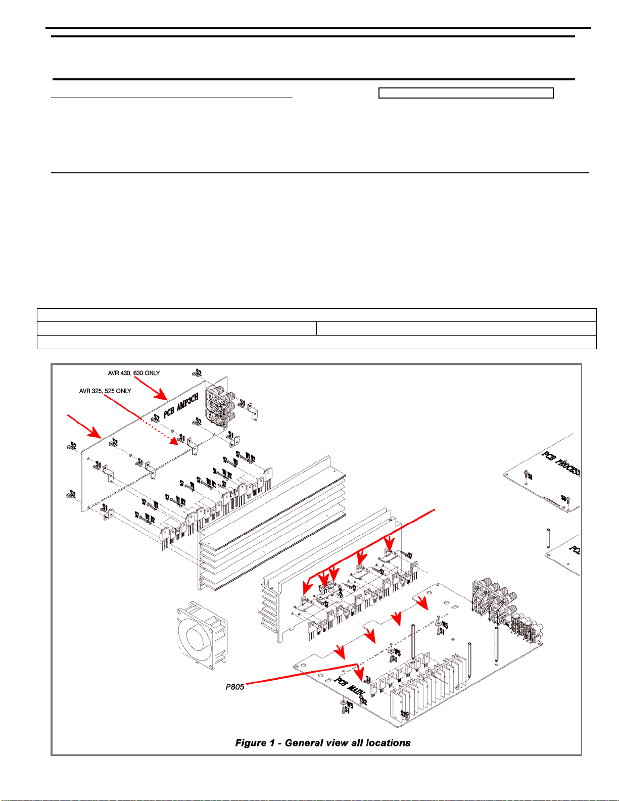
Page 19
AVR525 harman/kardon
19
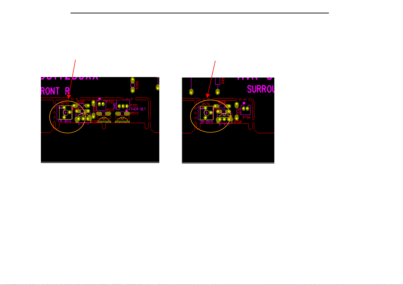
AVR325/525 Alignment spec. rev01.
1. MAIN B'D
: 5 Min. After power on, please set up Bias as below,
Front Left > adjusting VR71, check P801 to 23mV +2mV/- 1mV.
Surr Left > adjusting VR73 check P803 to 23mV +2mv/-1mV.
Front Right > adjusting VR74 check P804 to 23mV +2mV/-1mV.
Surr Right > adjusting VR72 check P802 to 23mV +2mV/-1mV.
P801 FRONT L-CH P803 SURROUND L-CH
Page 20
AVR525 harman/kardon
20
VR71 FRONT L-CH VR73 SURROUND L-CH
P804 FRONT R-CH P802 SURROUND R-CH
Page 21
AVR525 harman/kardon
21
VR74 FRONT R-CH VR72 SURROUND R-CH
Page 22
AVR525 harman/kardon
22
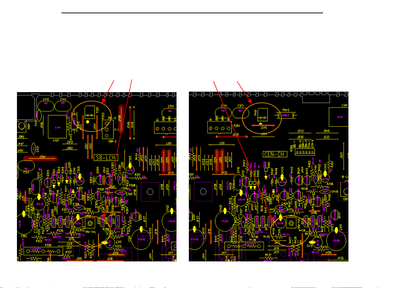
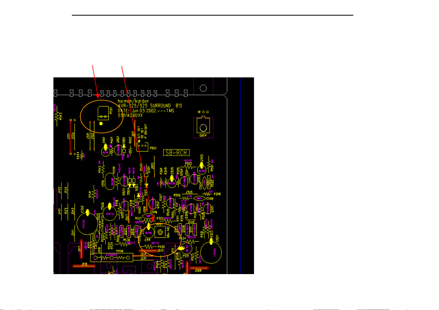
2. BACK SURROUND B'D
: 5 Min. After power on, please set up Bias as below,
SBL > adjusting VR31 check P301 to 23mV +2mv/-1mV.
Center > adjusting VR41 check P308 to 23mV +2mV/-1mV.
SBR > adjusting VR51 check P309 to 23mV +2mV/-1mV.
P301 VR31 BACK SURROUND L-CH VR41 P308 CENTER-CH
Page 23
AVR525 harman/kardon
23
P309 VR51 BACK SURROUND R-CH
Page 24
AVR525 harman/kardon
24
harman/kardon
Service Bulletin
Service bulletin # H/K2003-05 Sept. 2003
Warranty labor rate: MAJOR repair
To: All harman/kardon Service Centers
Model: AVR325/AVR525
Subject: Software Upgrade
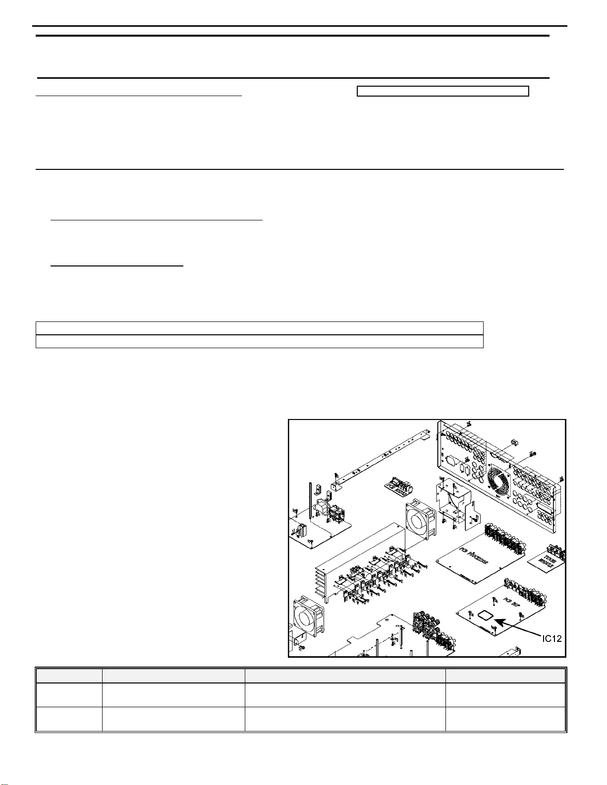
A software upgr ade is possible for the sub Micro CXP82852-375Q (IC12) in models AVR325 and AVR525;
units without the upgrade may exhibi t the following symptoms:
1) Dolby Digital EX mode only, Delay adjustment, any speaker size selected: Adjusting the delay time at 14 feet or
greater for surround back, surround or center channels, may generate a distortion (like a feedback signal) from the
subwoofer output. Lowering the delay level below 14 feet eliminates the distortion.
2) The Triple Crossover feature: Settings allow a different crossover point to be used for the front left/right, center
and surround speakers. If the settings are not configured properly, the user could actually create a frequency notch
and “cut out” certain bass frequencies, or, over-enhance bass frequencies by overlapping the X-Over points.
(NOTE: It would be a rare occurrence where symptom #2 would generate a complaint)
AVR325 IC12, (CXP82852-375Q) order and replace with h/k part # 55646260 (CXP82860-390Q).
AVR525 IC12, (CXP82852-377Q) order and replace with h/k part # 55645960 (CXP82860-391Q).
WARNING: FOLLOW PROPER STATIC CONTROL PROCEDURES and use caution during the removal of
the DSP board, and during installation of new IC12 to prevent damage.
Sub Micro CXP82852-375Q (IC12) is on the DSP board. Remove top cover, Processor board, all Molex connectors
and rear screws necessary to access DSP board.
Disengage both Processor and DSP PCB from the
rear PCB connector by pushing back on the rear
board; lift the Processor PCB up and out of the unit.
Not all connectors need to be removed – when
enough connectors are unplugged, the Processor
PCB can be lifted out of the way to access the DSP
board.
Disengage the DSP PCB from its rear connector by
pushing back on the rear PCB; lift the DSP PCB up
and out of the unit.
Locate and replace IC12; See drawing.
After replacement, replace all connectors and
screws. CAUTION: At the rear screws, if using a
power tool, use care and minimum force to avoid
damaging the various plastic receptacles.
Test the unit.
Model
AVR325
AVR525
Serial Number ( 120v)
All Seria l Numbers Affected
All Seria l Numbers Affected
Status Action
Dolby Digital Ex Mode Delay Adjustment
Oscillation; Triple Crossover
Dolby Digital Ex Mode Delay Adjustment
Oscillation; Triple Crossover
Change IC12
Change IC12
Page 25
AVR525 harman/kardon
25
harman/kardon Service Bulletin
Service bulletin # HK2004-04 Rev1 August 2005
To: All harman/kardon Service Centers
Model: AVR325, AVR525, AVR430, AVR630
Subject: Rewiring Bias/Fan cables
In the event you receive an AVR325, AVR525, AVR430 or AVR630 with the complaint: “the unit
intermittently goes in standby or the fan runs constantly” perform the following modification. Please
note other component or connection failures can cause the unit to go in to standby.
Synopsis: Hard wire Bias/Fan cables (7 cables, 12 connectors) from Bias PCB’s to main PCB, surround PCB.
Recheck all bias voltages.
1) Remove the top cover
2) Remove the DSP and Processor boards.
3) Locate and identify Bias cables connecting Bias and Surround PCB’s to main PCB:
All models MAIN PCB Location: P805, N801, N802, N803, N804
AVR430,630 SURROUND PCB Location: N301,P307 AVR325,525 SURROUND PCB Lo c ation: P 307, P310
All models BIAS PCB Location: P812, P813, P814, P815, P816
Warranty labor rate: MAJOR repair
Page 26
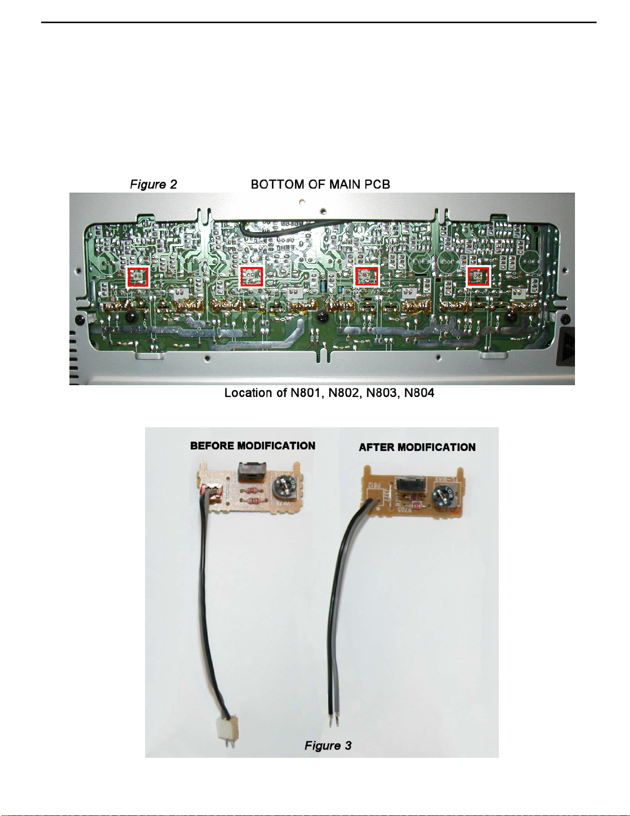
AVR525 harman/kardon
26
4) Unplug each the cable on the Bias PCB, desolder the female plugs, cut the connectors off each wire,
strip the insulation 1/8” on each end and solder directly to the PCB assembly in each location.
5) For locations N801, N802, N803, N804 on the Main PCB, set the unit on its side and remove the
bottom grille. (See Figure 2) Desolder and remove each connector. Cut the connectors off each wire,
strip the insulation 1/8” on each end and solder directly to the PCB assembly in each location.
6) For location P805 (see Figure 1) on the Main PCB, unplug the cable, carefully cut away the female
plug with diagonal cutters on the PCB surface, leaving the three conductors intact. Cut the connector
off each wire, strip the insulation 1/8” on each end, slide a piece of shrink tubing on each conductor
and solder each wire directly to the three conductors on the PCB. Heat the shrink tubing to complete
the connection, and add some silicon seal or similar adherent to affix the wires on the PCB.
Page 27
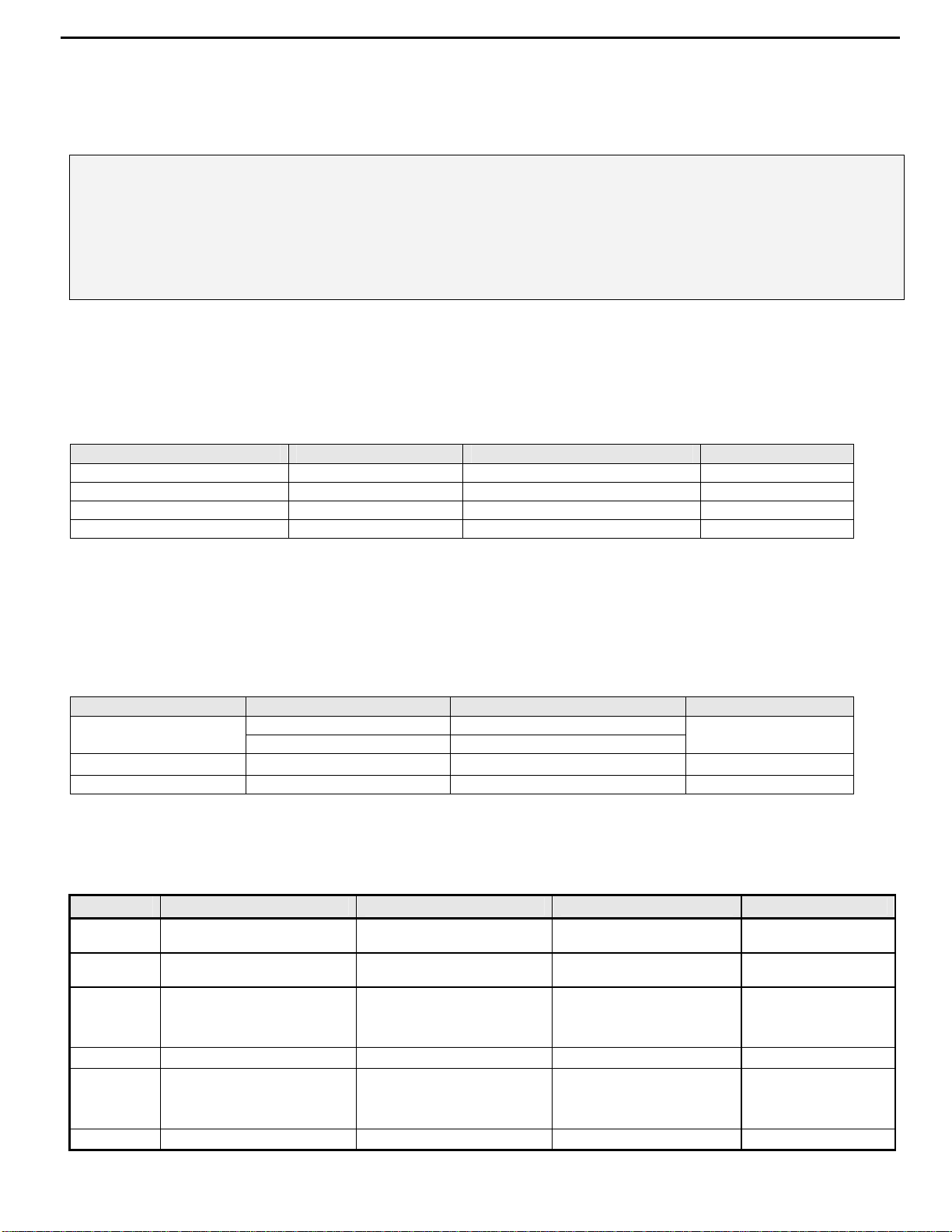
AVR525 harman/kardon
27
7) Replace the DSP and Processor boards
8) Recheck all bias voltages, following the instructions below:
MAIN AMP IDLE CURRENT ADJUSTMENT PROCEDURE
(Set variable resistors for MAIN/SURROUND Boa rd)
Specialized equipment/parts needed:
Variable AC transformer (“Variac” type) to adjust and monitor AC line voltage.
Two pin harness plug to connect DMM to idle current test points, hk part# 55212910NR or equivalent
Conditions:
No Signal; No Load
AC Line Voltage adjust to: 120V/60Hz (120v model) or 230V/50Hz (230v model)
After turning the unit ON for 25 minutes or more to keep the Power/Driver TR at normal temperature,
adjust the DC voltage at the two pin connector to the specified value by rotating the variable resistors.
VR71-74 are located on the Bias PCB’s.
P801-804 are located on the main PCB just below the Bias PCB’s. To guide/seat the two pin harness plug
into the sockets, you may have to attach the harness wire to a long blade screwdriver as P801-803 are in
a deep recess.
CHANNEL ADJUSTMENT M E ASUREME NT POI NT VOLTAGE
FRONT L CHAN VR71 P801 23mV ±2mV
FRONT R CHAN VR74 P804 23mV ±2mV
SURROUND L CHAN VR73 P803 23mV ± 2mV
SURROUND R CHAN VR72 P802 23mV ±2mV
SURROUND BACK A MP IDLE CURRENT ADJUSTMENT PROCEDURE
Same conditions as above.
After turning the unit ON for 25 minutes or more to keep the Power/Driver TR at normal temperature,
adjust the voltage value at the two pin connector to the specified value by rotating the variable resistors.
AVR325-525: VR31,41,51 and P301,308,309 are located at the center of the Surround PCB
AVR430-630: VR31,32,51 and P301,308,309 are located at the top edge of the Surround PCB
CHANNEL ADJUSTMENT MEASUREMENT POINT VOLTAGE
CENTER
SURROUND BACK L VR31 P301 23mV ±2mV
SURROUND BACK R VR51 P309 23mV ± 2mV
AVR325-525 VR41 P308
AVR430-630 VR32 P308
23mV ±2mV
9) After 5 minutes, check all voltages again at measurement points and re-adjust if necessary.
10) After more 5 minutes, check all voltages again at measurement points and re-adjust if necessary.
11) Replace the top cover and test the unit.
Model
AVR325
AVR525
AVR430
AVR430
AVR630
AVR630
Serial Number ( 120v) Ser i al Number (230v)
All serial num bers af f ected n/a
All serial num bers af f ected n/a
TF0001-01000
to
TF0001-08116
TF0007-08117 and above TF0007-06664 and above Modifi ed by Factory None Required
TF0002-01000
to
TF0002-11138
TF0002-11139 and above TF0007-05651 and above Modifi ed by Factory None Required
TF0006-01000
to
TF0006-06663
TF0007-01000
to
TF0007-05650
Unit may shut down or f an
Unit may shut down or f an
Unit may shut down or f an
Unit may shut down or f an
Status Action
may run conti nuously
may run conti nuously
may run conti nuously
may run conti nuously
Hard wire bias cables
to PCB’s
Hard wire bias cables
to PCB’s
Hard wire bias cables
to PCB’s
Hard wire bias cables
to PCB’s
Page 28

AVR525 harman/kardon
28
harman/kardon TECH TIPS
Troubleshooting tips and solutions to common service problems
For models:
AVR7000/7200/7300/8000
AVR100/200/300/500
AVR110/210/310/510
AVR120/220/320/520
AVR125/225/325/525
AVR130/230/330/430/630
AVR135/235/335/435/635
AVR10
DPR1001
DPR1005
DPR2005
HK3370/3470/3375/3475
HK3250
Subject: Backup Memory on AVR/DPR/HK series receivers
In the event of the complaint: “the receiver is losing its memory (any programmed system set t in gs)
when the unit is turned off, or after the unit is unplugged (briefly*)”:
Check and replace:
Model Designator Location Description Part number
AVR10
AVR7000 C730 Front PCB 0.047 Farad 5.5v capacitor
AVR7200 C106 Front PCB 0.047 Farad 5.5v capacitor # P10790-ND
AVR7300 C657 DSP PCB 0.047 Farad 5.5v capacitor # H01-CEZXA0479MN-5
AVR8000 C726 Front PCB 0.047 Farad 5.5v capacitor
AVR100/200 C412 Front PCB 0.047 Farad 5.5v capacitor # CEGT-B473J-0J0
AVR300 C906 Front PCB 0.1Farad 5.5v capacitor
AVR500 C906 Front PCB 0.1Farad 5.5v capacitor
AVR110/210/310/510
AVR120/220/320/520
AVR125/225 C734,C885 Front PCB two 0.1F capacitors in parallel # BCESOHD104
AVR325/525 C106 Front PCB 0.047 Farad 5.5v capacitor # P10790-ND
AVR130/230/330 BAT1 Front PCB 3.6v Battery # HABGP40BVH3A3H
AVR135/235/335 BAT1 Front PCB 3.6v Battery # HGP15BNH3A3H
AVR430/630 C657 DSP PCB 0.047 Farad 5.5v capacitor # CEZXA0479MN-5
AVR435/635 C557 DSP PCB 0.047 Farad 5.5v capacitor # H03-CEZXA0479MN-0
DPR1001 BC601 Main PCB 0.1Farad 5.5v capacitor # CEGT-B104J-0J0
DPR1005/2005 C437
HK3370/3470 C301 Front PCB 0.1Farad 5.5v capacitor # CEGT-B104J-0J0
HK3375/3475 C301 Front PCB 0.1Farad 5.5v capacitor # CEGT-B104J-0J0
HK3250
* After approximately two weeks of being disconnected from A C suppl y , even a nor mall y functioning receiver may
lose any program med settings and switch t o default settings. (Four weeks for the DPR1005 & 2005)
C712
D709
C216 Front PCB 0.047 Farad 5.5v capacitor # P10790-ND
C712
D709
Front PCB
Processor
PCB
Front PCB
0.047 Farad 5.5v capacitor
and 1N4148 diode
0.047 Farad 5.5v capacitor # CEZXA0479MN-5
0.047 Farad 5.5v capacitor
and 1N4148 diode
TIP# HKTT2003-01 Rev5
#3439247315
#2058322101
# P10790-ND or
# J3432147324X
# 55230310NR or
# P10790-ND
# J4433210421X
or # P10791-ND
# J4433210421X
or # P10791-ND
#3439247315
#2058322101
Page 29

AVR525 harman/kardon
29
harman/kardon TECH TIPS
Troubleshooting tips and solutions to common service problems
TIP# HKTT2004-03
Isolating audio problems in an AVR receiver
Using 6/8 Direct In
The following charts are used to help the tech quickly isolate
audio problems in an AVR receiver. Use the following
procedures to help find what is working, then to quickly locate
the problem area.
Equipment needed:
9 1 set of (RCA) Y adaptors.
9 Function/signal generator.
9 Oscilloscope.
Procedure:
1) Do a factory reset of the receiver. (This will eliminate any common micro processor
problems.) Reset List can be found in this service manual.
2) Print the block diagram from the service manual.
3) With no inputs or speakers attached to the AVR turn on the receiver and turn the
volume all the way down.
4) Turn unit off.
5) Hook up an oscillator to the 6/8 Direct in jacks using the Y adaptors. Adjust the
oscillator to about 0db (.775Volts RMS).
6) Hook up an oscilloscope to monitor the line out jacks. Or, if there are no line out
(preamp out) jacks monitor the input to the power amps or the speaker outs.
(AVR125, 225, 130 do not have preamp out jacks)
7) Turn the AVR on. Select 6 or 8 direct in, depending on the receiver.
8) Slowly turn the volume control up until you can easily measure the voltage at the line
out jacks. ( -40 to -25db )
Models covered:
AVR210 AVR310
AVR220 AVR320
AVR520 AVR225
AVR125 AVR525
AVR130 AVR230
AVR330 AVR430
AVR630
Harman Consumer Group 250 Crossways Park Dr. Woodbury, New York 11797
Email Techsupport@harman.com
Page 30
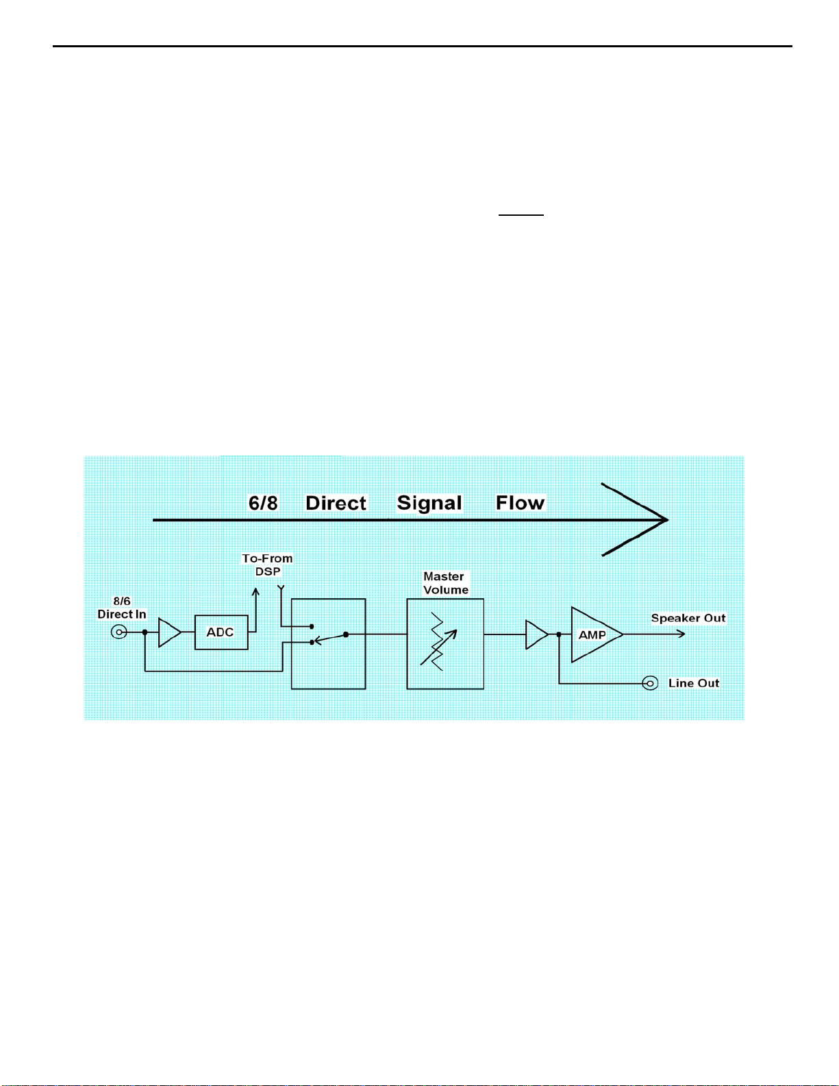
AVR525 harman/kardon
30
Isolating audio problems in an AVR receiver
Using 6/8 Direct In
9) At this point you will be able to check and assure all output levels are the same.
10) IF THE OUTPUT LEVELS ARE NOT THE SAME
you will need to use the charts to see where you are losing your signal. The chart
shows the analog signal flow from the input jacks to the output jacks.
11) If the output levels are the same check the power out stage at the speaker out jacks.
12) If you find the levels at the speaker out jacks are OK, your problem will be in the DSP
part of the receiver.
Congratulations! You have now eliminated 90% of the electronics in the AVR and
confirmed that the problem is in the DSP section.
STOP! Go no further. At this point
Harman Consumer Group 250 Crossways Park Dr. Woodbury, New York 11797
Email Techsupport@harman.com
Page 31

AVR525 harman/kardon
31
Isolating audio problems in an AVR receiver
Using 6/8 Direct In
AVR,210,310,510
t
u
n
I
N
I
CH
6
FR 3 1 15 2 4 8 9 4 3 19 17 3 1 3
FL 5 7 13 27 25 21 20 25 26 10 12 5 7 1
SR 11 5 7 7 6 5 7 9
SL 9 24 22 22 23 3 1 7
C 5 21 19 19 20 3 1 5
SW 7 8 10 10 9 5 7 11
I
O
1
1
0
5
C
08
0
4
5
N
C
I
C
C
I
t
u
n
I
O
4
4
0
0
7
C7
C7
I
I
t
u
n
I
O
5
5
0
0
C7
C7
I
I
t
u
O
n
I
6
6
0
0
7
7
C
C
I
I
AVR220
t
u
n
O
I
N
I
CH
6
FR 5 7 15 2 4 8 9 4 3 5 7 10 12 5 7 1
FL 3 1 13 27 25 21 20 25 26 3 1 19 17 3 1 3
SR 11 5 7 7 6 5 7 9
SL 9 24 22 22 23 3 1 7
C 5 21 19 19 20 3 1 5
SW 7 8 10 10 9 5 7 11
1
0
5
C
I
8
1
0
0
4
5
C
C
CN
I
I
t
u
n
I
O
4
4
0
0
7
C7
C7
I
I
t
u
n
I
O
5
5
0
0
C7
C7
I
I
t
u
O
n
I
6
6
0
0
7
C
C7
I
I
t
u
n
O
I
5
5
0
0
7
7
C
C
I
I
t
u
n
I
O
4
4
1
1
7
C
C7
I
I
t
u
n
I
O
6
6
1
1
7
C7
C
I
I
t
u
n
O
I
5
5
0
0
7
7
C
C
I
I
t
u
n
I
O
7
7
1
1
7
7
C
C
I
I
t
u
n
I
O
6
6
1
1
7
C7
C
I
I
t
u
n
I
O
8
1
n
I
7
1
5
8
0
1
4
7
P
C
I
C
t
u
O
7
1
7
7
C
C
I
I
t
u
n
I
O
8
1
5
8
0
1
4
7
C
I
CP
AVR320/520
t
u
n
O
I
C
I
CN4
1
0
5
8
1
I
CP
8
1
0
0
4
5
C
C
CN
I
n
I
2
1
0
0
1
C1
C1
I
I
N
I
CH
8
FR 5 7 15 2 4 8 9 4 3 5 7 10 12 5 7 1
FL 3 1 13 27 25 21 20 25 26 3 1 19 17 3 1 3
SR 11 5 7 7 6 5 7 9
SL 9 24 22 22 23 3 1 7
C 5 21 19 19 20 3 1 5
SW 7 8 10 10 9 5 7 11
SBR 3 3 3 4 21 23 5 7
SBL 1 1 25 26 4 2 3 1
t
u
n
I
O
4
4
0
0
7
C7
C7
I
I
t
u
n
I
O
1
2
0
0
1
C1
c
i
I
t
u
n
I
O
5
5
0
0
C7
C7
I
I
UT
N
i
o
2
3
0
0
0
1
1
c
c
i
i
t
u
O
n
I
6
6
0
0
7
C
C7
I
I
t
u
O
3
t
u
n
I
O
4
4
1
1
7
C
C7
I
I
t
u
n
O
I
5
5
0
0
7
C
C
I
I
t
u
n
I
O
6
6
1
1
7
7
C7
C
I
I
t
u
n
I
7
1
C
I
n
O
I
7
1
7
C
I
O
8
8
1
1
7
7
C
I
AVR225/125
t
t
u
u
N
I
CH
6
L ch 27 25 19 20 5 7 1 3 1 9 10 1 2
R ch 24 22 22 23 3 1 3 5 7 15 14 4 5
SL 5476 579
SR 2 4 10 9 3 1 11
C 81843 31 7
SW 21 19 25 26 5 7 5
n
I
0
3
C
I
n
O
I
0
3
C
I
O
1
1
3
3
C
C
C
I
I
I
t
u
n
I
O
2
2
3
3
C
C
I
I
t
u
n
I
O
3
3
3
3
C
C
I
I
t
u
n
O
I
4
3
2
4
3
N1
C
I
C
I
B
t
u
n
O
I
1
1
8
8
C
C
I
I
t
u
n
I
O
0
0
8
8
N1
C
I
B
t
u
n
O
I
6
6
N1
B
t
u
5
0
4
CP
Harman Consumer Group 250 Crossways Park Dr. Woodbury, New York 11797
Email techsupport@harman.com
Page 32

AVR525 harman/kardon
32
Isolating audio problems in an AVR receiver
Using 6/8 Direct In
AVR 525
t
t
k
c
a
J
n
I
FL 11 109 423 135 3 1 1 1
FR 3 3 21 22 21 23 5 7 28 6 6 7 3 3
SL 5524 43 3 1 5 5
SR 7 7 29 27 25 26 5 7 7 7
CTR 9957 76 3 1 9 9
SW 11 11 26 24 22 23 5 7 11 11
SBL 13 13 8 10 10 9 3 1 13 13
SBR 15 15 23 21 19 20 6 7 15 15
4
0
6
N4
P
u
n
I
O
C5
C5
I
I
t
u
n
O
I
C3
C3
I
I
u
n
n
O
I
I
9
C1
I
8
9
C1
C1
I
C2
I
I
t
u
n
I
O
0
n
I
0
C3
C2
I
C3
I
I
t
u
t
u
O
O
8
C2
C1
I
I
t
u
n
I
O
3
3
C2
C2
I
I
AVR130
t
n
i
h
c
6
L18172123 1
R191242 14
SL 24 22 21 23 9
SR 57 42 7
C27252123 5
SUB 2 4 4 2 3
SBL 21 19 21 23 5 7 13
SBR 8 10 4 2 3 1 11
n
I
3
2
C
I
I
n
I
u
u
O
O
6
2
3
6
2
2
C
I
C
C
I
t
t
n
u
I
O
2
4
2
C
I
C4
I
t
n
I
u
O
4
4
4
4
C
I
I
C
I
t
n
I
u
O
3
4
3
4
C
C
I
t
n
u
I
O
0
4
0
C
I
C4
I
t
n
I
9
4
C
I
C4
I
2
u
O
9
1
1
N1
N
B
B
t
u
n
O
I
5
5
C2
C2
I
I
t
u
n
I
O
4
4
C2
C2
I
I
t
u
n
I
O
6
6
C2
I
6
0
9
P
N8
AVR230/330
t
n
i
h
c
6
L18172123 1
R191242 14
SL 24 22 21 23 9
SR 57 42 7
C27252123 5
SUB 2 4 4 2 3
SBL 21 19 21 23 5 7 13
SBR 8 10 4 2 3 1 11
n
I
3
2
C
I
I
n
I
u
u
O
O
6
2
3
6
2
2
C
I
C
C
I
t
t
n
u
I
O
2
4
2
C
I
C4
I
t
n
I
u
O
4
4
4
4
C
I
I
C
I
t
n
I
u
O
3
4
3
4
C
C
I
t
n
u
I
O
0
4
0
C
I
C4
I
t
n
I
9
4
C
I
C4
I
2
u
O
9
1
1
N1
N
B
B
AVR630/430
t
n
I
CH
8
FL 11012109316931423131
FR 319171920 5 72320 5 7 2123 5 7 26 7
SL 52443 31
SR 727252526 5 7
CTR 95776 3 1
SW 11 24 22 22 23 5 7
SBL 13 8 10 10 9 3 1
SBR 15 21 19 19 20 5 7
4
0
N4
4
0
N4
u
O
3
3
C
C
C
I
I
I
t
u
n
I
O
5
5
C1
C
C
I
I
I
t
u
n
I
O
4
4
1
1
C
C
I
I
t
u
n
O
I
9
9
1
C
C
I
I
t
t
u
n
I
2
2
1
1
C
I
n
I
5
5
2
2
C
I
u
O
n
I
O
3
3
C
I
t
u
O
C
I
C
C
I
I
t
u
n
I
O
4
4
2
2
C
C
I
I
t
u
n
I
O
7
7
2
2
C
C
I
I
t
u
n
O
I
6
6
2
2
C
I
t
u
n
O
I
8
8
1
1
C
C
I
I
t
u
n
I
O
0
0
2
2
C
C
I
I
t
u
n
I
O
3
3
C
I
Harman Consumer Group 250 Crossways Park Dr. Woodbury, New York 11797
Email techsupport@harman.com
Page 33

AVR525 harman/kardon
33
Page 34

AVR525 harman/kardon
34
AVR 525 EXPLODED VIEW PARTS LIST
# Part Number Q'ty Description
1 55178050XX 1
2 55142780NR 1 DISPLAY HNA-15LL01
3 55050690XX 1 CONN-PHJAC 6.35 ST HORZ CKX3-6.35-04 BK 0 0
4 55124350XX 1
5 55178000NR 1 SW PUSH POWER SWITCH 5.0A 250.0V 100MI0OHM 1T 2P
6 55178020XX 1
7 55177810XX 1 AC DEC BUTTON POWER
8 55177820XX 1
9 55405780XX 1 AC DEC CABINET PANEL FRONT 525
10 55177800XX 1
11 55191560XX 1 AC NON-METAL DIFFUSER 0.2T 62.5*41 WH
12 55177740XX 1
13 55405940XX 1
14 55177990XX 1
15 55177750XX 3
16 55178030XX 2
17 55445260XX 1 AC DEC BUTTON 7 KEY
18 55125440XX 3 D-LEM TOTX178B RD RND CL
19 55175950XX 1 CON PHONO SCKT RCA 1P W/GND JE010003MN
20 55182550XX 1
21 55445110XX 1
22 55445160XX 1 AC DEC BUTTON 5 KEY
23 55174760XX 4 AC FOOT RUBBER ROUND 3.0MM 25.0MM JIS 60 Y DIA
24 55445360XX 4 AC FOOT ASSY ROUND 12.5MM 50MM
25 55406540XX 1
26 55171510XX 1 CON PHONO SCKT RCA-313P 3 PINS
27 55179910OO 1 PR-ROT 100K0 OHM NON-LINEAR RK14K12400BQ 0 0
28 55113960XX 1 CON DIN SCKT SOCKET CONNECTOR SVHS EST-S408J
29 55179920OO 2 PR-ROT 100K0 OHM NON-LINEAR RK14K12400BR 0 0
30 55177570XX 1
31 55134900NR 1 SWIROT EC16B24204A5 5V 500U0A 10T 3P 0 0
32 55191530XX 1
33 55178940XX 1
34 55178440XX 1
35 55155930XX 1 IC-REMOTE RPM6938-RSIP-A3 RECEIVER 38KH
36 55177960XX 1 AC NON-METAL DIFFUSER REFLECTOR C WH
37 55178930XX 1
38 55406440XX 1
39 55506280NR 1 TF-LAM POWER-TRANSFORMER 120V
40 55406640XX 1
41 55406840XX 1 AC PUN BRACKET FAN FRONT AVR325/525
42 55509100XX 1 FAN RDL8025B C185HS10H1910 ( WIRE:300MM) 0 A0
43 55436090XX 1 CONN-SPE TERMINAL SPKR 6P SH0611708P FE 19MM 6
44 55168710XX 6
45 55406340XX 1
46 55149520XX 7 CON DIN SCKT MIX SOCKET RCA-118JP1S
47 55436080XX 1 CON PHONO SCKT RCA 9P W/GNDCAP JW-4109RS
48 55178170XX 2
49 55222020XX 2
50 55407240XX 1 AC METAL STANDOFF HEX MF M4X8 6MMOD 111.2H
51 55176410XX 1 AC METAL HEATSINK 17*15*30 AVR525 -52 55222010XX 1 CON MAINS INLET A/C INLET 7014-NGP
53 55206550NR 1 CONN-SPE AC OUTLET 2P 110V FE 12.75MM 2 BK 0 0
54 55615050 1 EPR TUNER MODULE KST-M1011MW0-62 AVR525 OEM US
55 55555910XX 1 AC METAL HEATSINK(MAIN) AVR525 -56 BLANK
57 55509110XX 1 FAN RDL8025B C185HS10H1910 ( WIRE:400MM) 0 A0
58 55406940XX 1
59 55246370XX 1 CON PHONO SCKT RCA 1P W/GND JE010003LN OG
60 55125440NR 1 D-LEM TOTX178B RD RND C
61 55191600XX 1 CON PHONO SCKT RCA 2P W/GNDCAP JW-1502SN OO
62 55191420XX 2 CON PHONO SCKT RCA 4P JW-4104RSA
63 55191450XX 2 CON PHONO SCKT RCA 4P JW-4104RSC
AC PUN COVER TOP
AC PUN BRACKET HEADPHONE
AC MLD BUTTON INDICATOR STAND-BY
AC DEC BUTTON STANDBY
AC DEC CRYSTAL FILTER DISPLAY
AC DEC KNOB MAIN HIPS 94H
AC DEC CRYSTAL DISPLAY AVR525
AC NON-METAL DIFFUSER 0.2T 59.6*41 WH
AC DEC KNOB TONE
AC MLD BUTTON INDICATOR VIDEO 4
AC PUN SHIELD DIGITAL ET
AC DEC BUTTON 3 KEY
AC CPL CABINET CHASSIS MAIN SECC 1.0T
AC PUN SHIELD FENCE TONE
AC PLASTIC MOLD REFRACTOR B WH
AC PLASTIC MOLD REFRACTOR E WH
AC MLD HOLDER FL-GUIDE
Z
AC PLASTIC MOLD REFRACTOR F WH
AC CPL CABINET CHASSIS FRONT AVR325/525
AC PUN COVER TRANS BOTTOM AVR325/525 --
AC PUN BRACKET HEATSINK SECIT RT2250(PAV5005)
AC METAL HEATSINK(AMP) 3CH AVR525 --
AC PUN BRACKET FRAME-GUIDE SECC T1.0
AC PUN BRACKET AC INLET
AC PUN BRACKET FAN REAR AVR325/525
L
/
Page 35

A
A
A
A
-
A
A
-
A
-
A
X
A
L
AVR525 harman/kardon
35
64 55405680XX 1
65 55554510 1
66 67472300NR 1 CONN-SPE 87204-6063 SUB D FE 2.77MM 9 -- 1630 A1
67 55176390XX 3 CON PHONO SCKT STEREO JACK JW350S
68 55176420XX 1
69 55176330XX 5 CON PHONO SCKT RCA 4P JW4104RS GND
70 55407040XX 4
71 55426050XX 1 JACK-TELE SNAP-IN GOLDEN TELECOM GDL1-8P8C
72 55436070NR 1 CONN-SPE TERMINAL SPKR 8P SH081136JP
73 55176400XX 1
74 55407140XX 4
75 55212250XX 2 CABLE-FIX CLAMP WIRE UL DENNISON 0 0
76 55406740XX 1
77 55125220XX 3
55178960XX 1
X
S1 55127070XX 72 SCREW-ST 3MM 10MM
S2 55127120XX 31 SCREW-ST 3MM 8MM
S3 55309240XX 4 SCREW-BM 4MM 10MM
S4 55127090XX 8 SCREW-ST 4MM 8MM
S5 55127280XX 5 SCREW-ST 3MM 6MM
S6 55164800XX 1 SCREW-ST 3MM 8MM
S7 55178320XX 35 SCREW-ST 3MM 12MM
S8 55231250XX 5 SCREW 4MM 8MM
S9 55178340XX 4 SCREW-ST 4MM 10MM
SG 55135460XX 46 SCREW-ST 3MM 10MM
SF 55453660XX 8 SCREW-ST 5MM 10MM
N1 55309350XX 4 NUT-HEXAGON 4.0MM 5.0MM CIRCULAR EXTERNA
C CPL REAR PANEL AVR525
C PLASTIC DUST COVER AVR325/525
C PUN BRACKET BKT GROUND ET 0.5T AVR520
C METAL STANDOFF HEX MF M4X8 6MMOD 31.9H -
C METAL HEATSINK REG 118*20*50H
C METAL STANDOFF HEX MF M4X8 6MMOD 61.9H -
C PUN COVER BOTTOM AVR325/525 C BUFFER PCB
C SPRING PLATE SPRING GND C5212 0.2T
W1 55127300XX 35 WASHER-SPRING 3
W2 55127310XX 14 WASHER-FLAT 3
W3 55168690XX 4 WASHER-SPRING 4
W4 55131730XX 4 WASHER-FLAT 4
W5 20372500XX 3 WASHER FIBER 3 X 7.9 X 0.8T
Page 36

g
r
B
s
0
V
V
V
0
V
V
V
0
V
V
V
s
A
AVR525 harman/kardon
36
AVR525 Electrical Parts List
Ref.
nato
Desi
SURROUND PC
Capacitor
C301 13076940AM 1 PC
C302 13076940AM 1 PC
C303 2026888030 1 PC
C304 7042839071 1 PC
C305 2026907030 1 PC
C306 4043358071 1 PC
C307 2024633071 1 PC
C308 2026908030 1 PC
C309 8043472071 1 PC
C310 5517940071 1 PC
C311 2026888030 1 PC
C312 2026888030 1 PC
C313 5517936071 1 PC
C314 5517936071 1 PC
C320 1105558071 1 PC
C331 1105556071 1 PC
C401 13076940AM 1 PC
C402 13076940AM 1 PC
C403 2026888030 1 PC
C404 7042839071 1 PC
C405 2026907030 1 PC
C406 4043358071 1 PC
C407 2024633071 1 PC
C408 2026908030 1 PC
C409 8043472071 1 PC
C410 5517940071 1 PC
C411 2026888030 1 PC
C412 2026888030 1 PC
C413 5517936071 1 PC
C414 5517936071 1 PC
C420 1105558071 1 PC
C431 1105556071 1 PC
C501 13076940AM 1 PC
C502 13076940AM 1 PC
C503 2026888030 1 PC
C504 7042839071 1 PC
C505 2026907030 1 PC
C506 4043358071 1 PC
C507 2024633071 1 PC
C508 2026908030 1 PC
C509 8043472071 1 PC
C510 5517940071 1 PC
C511 2026888030 1 PC
C512 2026888030 1 PC
C513 5517936071 1 PC
C514 5517936071 1 PC
C520 1105558071 1 PC
C531 1105556071 1 PC
C601 1500213030 1 PC
Part Number Qty Description
CE 470U0F +20% 63.0V 85C
CE 470U0F +20% 63.0V 85C
CE 10U0F +20% 50.0V 85C
CC 270P0F +10% -10% 50.0V Y5P
CE 100U0F +20% 25.0V 85C
CC 680P0F +10% -10% 50.0V Y5P
CC 3P0F +0P25F -0P25F 50.0V NP
CE 220U0F +20% 10.0V 85C
CC 180P0F +10% -10% 50.0V Y5P
CPM 68N0F +5% 63.0
CE 10U0F +20% 50.0V 85C
CE 10U0F +20% 50.0V 85C
CPM 100N0F +10% 63.0
CPM 100N0F +10% 63.0
CC 4N7F +10% -10% 50.0V Y5P
CC 3N3F +10% -10% 50.0V Y5P
CE 470U0F +20% 63.0V 85C
CE 470U0F +20% 63.0V 85C
CE 10U0F +20% 50.0V 85C
CC 270P0F +10% -10% 50.0V Y5P
CE 100U0F +20% 25.0V 85C
CC 680P0F +10% -10% 50.0V Y5P
CC 3P0F +0P25F -0P25F 50.0V NP
CE 220U0F +20% 10.0V 85C
CC 180P0F +10% -10% 50.0V Y5P
CPM 68N0F +5% 63.0
CE 10U0F +20% 50.0V 85C
CE 10U0F +20% 50.0V 85C
CPM 100N0F +10% 63.0
CPM 100N0F +10% 63.0
CC 4N7F +10% -10% 50.0V Y5P
CC 3N3F +10% -10% 50.0V Y5P
CE 10U0F +20% 16.0V 85C
Semiconductor
D301 7043654016 1 PC
D-SLP 1N4148 100.0V 150E-3
Page 37

g
r
B
A
A
A
A
A
A
A
A
A
A
A
A
V
V
V
A
V
V
V
V
V
V
V
V
V
V
A
A
A
A
V
V
V
V
A
V
V
V
V
V
V
V
V
V
V
A
A
A
A
V
V
V
V
A
V
V
V
AVR525 harman/kardon
37
Ref.
nato
Desi
SURROUND PC
D302 7043654016 1 PC
D303 7043654016 1 PC
D304 7043654016 1 PC
D401 7043654016 1 PC
D402 7043654016 1 PC
D403 7043654016 1 PC
D404 7043654016 1 PC
D501 7043654016 1 PC
D502 7043654016 1 PC
D503 7043654016 1 PC
D504 7043654016 1 PC
D601 7043654016 1 PC
Q301 2055660056 1 PC
Q302 2055660056 1 PC
Q303 2055660056 1 PC
Q304 2050808056 1 PC
Q305 5523309056 1 PC
Q306 2064785056 1 PC
Q307 2055660056 1 PC
Q308 5513326056 1 PC
Q309 5513324056 1 PC
Q311 5513326056 1 PC
Q312 5513324056 1 PC
Q313 5513324056 1 PC
Q314 551332700 1 PC
Q315 5513326056 1 PC
Q316 551791900 1 PC
Q317 551792000 1 PC
Q318 551791800 1 PC
Q319 551791500 1 PC
Q320 2055660056 1 PC
Q401 2055660056 1 PC
Q402 2055660056 1 PC
Q403 2055660056 1 PC
Q404 2050808056 1 PC
Q405 5523309056 1 PC
Q406 2064785056 1 PC
Q407 2055660056 1 PC
Q408 5513326056 1 PC
Q409 5513324056 1 PC
Q411 5513326056 1 PC
Q412 5513324056 1 PC
Q413 5513324056 1 PC
Q414 551332700 1 PC
Q415 5513326056 1 PC
Q416 551791900 1 PC
Q417 551792000 1 PC
Q418 551791800 1 PC
Q419 551791500 1 PC
Q420 2055660056 1 PC
Q501 2055660056 1 PC
Q502 2055660056 1 PC
Q503 2055660056 1 PC
Q504 2050808056 1 PC
Q505 5523309056 1 PC
Q506 2064785056 1 PC
Q507 2055660056 1 PC
Part Number Qty Description
D-SLP 1N4148 100.0V 150E-3
D-SLP 1N4148 100.0V 150E-3
D-SLP 1N4148 100.0V 150E-3
D-SLP 1N4148 100.0V 150E-3
D-SLP 1N4148 100.0V 150E-3
D-SLP 1N4148 100.0V 150E-3
D-SLP 1N4148 100.0V 150E-3
D-SLP 1N4148 100.0V 150E-3
D-SLP 1N4148 100.0V 150E-3
D-SLP 1N4148 100.0V 150E-3
D-SLP 1N4148 100.0V 150E-3
D-SLP 1N4148 100.0V 150E-3
TR-SHPLF KTC3200BL N 100MI0A 120
TR-SHPLF KTC3200BL N 100MI0A 120
TR-SHPLF KTC3200BL N 100MI0A 120
TR-SLPLF KTC3198BL N 150MI0
TR-SLPLF 2SA1145Y TO-92MOD P -50MI0A -150
TR-SHPLF KTA1268BL P 100MI0A 120
TR-SHPLF KTC3200BL N 100MI0A 120
TR-SLPLF KTA1024 Y P 50MI0A -150
TR-SLPLF KTC3206 Y N 50MI0A 150
TR-SLPLF KTA1024 Y P 50MI0A -150
TR-SLPLF KTC3206 Y N 50MI0A 150
TR-SLPLF KTC3206 Y N 50MI0A 150
TR-SHPLF 2SC4137 N 100MI0A 20
TR-SLPLF KTA1024 Y P 50MI0A -150
TR-SHPLF 2SA1859A P -2.0
TR-SHPLF 2SC4883A N 2.0
TR-SHPLF 2SC5358-R N 15.0
TR-SHPLF 2SA1986-R P -15.0
TR-SHPLF KTC3200BL N 100MI0A 120
TR-SHPLF KTC3200BL N 100MI0A 120
TR-SHPLF KTC3200BL N 100MI0A 120
TR-SHPLF KTC3200BL N 100MI0A 120
TR-SLPLF KTC3198BL N 150MI0
TR-SLPLF 2SA1145Y TO-92MOD P -50MI0A -150
TR-SHPLF KTA1268BL P 100MI0A 120
TR-SHPLF KTC3200BL N 100MI0A 120
Page 38

g
r
B
V
V
V
V
V
V
V
A
A
A
A
V
V
s
AVR525 harman/kardon
38
Ref.
nato
Desi
SURROUND PC
Q508 5513326056 1 PC
Q509 5513324056 1 PC
Q511 5513326056 1 PC
Q512 5513324056 1 PC
Q513 5513324056 1 PC
Q514 551332700 1 PC
Q515 5513326056 1 PC
Q516 551791900 1 PC
Q517 551792000 1 PC
Q518 551791800 1 PC
Q519 551791500 1 PC
Q520 2055660056 1 PC
Q601 2064785056 1 PC
Resistor
R301 6044155016 1 PC
R302 3093949016 1 PC
R303 5523281016 1 PC
R304 2046951016 1 PC
R305 2046945016 1 PC
R306 2046945016 1 PC
R307 2046945016 1 PC
R308 5088297016 1 PC
R309 5088299016 1 PC
R310 5088299016 1 PC
R311 6044156016 1 PC
R312 5549851016 1 PC
R313 5549850016 1 PC
R314 6044156016 1 PC
R315 6044156016 1 PC
R316 6044156016 1 PC
R317 6044156016 1 PC
R318 6044156016 1 PC
R319 9057109016 1 PC
R320 5088301016 1 PC
R321 5088301016 1 PC
R322 9057109016 1 PC
R323 9057109016 1 PC
R324 9057109016 1 PC
R325 5523281016 1 PC
R326 5088295016 1 PC
R327 4043891016 1 PC
R328 3093937016 1 PC
R329 8043700016 1 PC
R330 6044155016 1 PC
R333 5523281016 1 PC
R334 1105959016 1 PC
R335 3093937016 1 PC
R336 5088295016 1 PC
R337 4043891016 1 PC
R338 551793400 1 PC
R339 4043563016 1 PC
R340 5088301016 1 PC
R341 4043563016 1 PC
R342 9057113016 1 PC
R343 5524229016 1 PC
Part Number Qty Description
TR-SLPLF KTA1024 Y P 50MI0A -150
TR-SLPLF KTC3206 Y N 50MI0A 150
TR-SLPLF KTA1024 Y P 50MI0A -150
TR-SLPLF KTC3206 Y N 50MI0A 150
TR-SLPLF KTC3206 Y N 50MI0A 150
TR-SHPLF 2SC4137 N 100MI0A 20
TR-SLPLF KTA1024 Y P 50MI0A -150
TR-SHPLF 2SA1859A P -2.0
TR-SHPLF 2SC4883A N 2.0
TR-SHPLF 2SC5358-R N 15.0
TR-SHPLF 2SA1986-R P -15.0
TR-SHPLF KTC3200BL N 100MI0A 120
TR-SHPLF KTA1268BL P 100MI0A 120
RCF 330R0 OHM +5% 250MI0W
RCF 33K0 OHM +5% 250MI0W
RMF 10R0 OHM +5% 500MI0W
RCF 43K0 OHM +5% 250MI0W
RCF 220R0 OHM +5% 250MI0W
RCF 220R0 OHM +5% 250MI0W
RCF 220R0 OHM +5% 250MI0W
RCF 470R0 OHM +5% 250MI0W
RCF 1K6 OHM +5% 250MI0W
RCF 1K6 OHM +5% 250MI0W
RCF 560R0 OHM +5% 250MI0W
RMF 33K0 OHM +1% 250MI0W
RMF 1K45 OHM +1% 250MI0W
RCF 560R0 OHM +5% 250MI0W
RCF 560R0 OHM +5% 250MI0W
RCF 560R0 OHM +5% 250MI0W
RCF 560R0 OHM +5% 250MI0W
RCF 560R0 OHM +5% 250MI0W
RCF 200R0 OHM +5% 250MI0W
RCF 15K0 OHM +5% 250MI0W
RCF 15K0 OHM +5% 250MI0W
RCF 200R0 OHM +5% 250MI0W
RCF 200R0 OHM +5% 250MI0W
RCF 200R0 OHM +5% 250MI0W
RMF 10R0 OHM +5% 500MI0W
RCF 100R0 OHM +5% 250MI0W
RCF 2R2 OHM +5% 250MI0W
RCF 15R0 OHM +5% 250MI0W
RCF 1K2 OHM +5% 250MI0W
RCF 330R0 OHM +5% 250MI0W
RMF 10R0 OHM +5% 500MI0W
RCF 82R0 OHM +5% 250MI0W
RCF 15R0 OHM +5% 250MI0W
RCF 100R0 OHM +5% 250MI0W
RCF 2R2 OHM +5% 250MI0W
RW 220MI0 OHM +5% 5.0W 100PPM/'C -100PPM/'C
RCF 1K5 OHM +5% 250MI0W
RCF 15K0 OHM +5% 250MI0W
RCF 1K5 OHM +5% 250MI0W
RCF 39K0 OHM +5% 250MI0W
RCF 10R0 OHM +5% 250MI0W
Page 39

g
r
B
AVR525 harman/kardon
39
Ref.
nato
Desi
SURROUND PC
R344 6044158016 1 PC
R345 6044255016 1 PC
R346 3093951016 1 PC
R401 6044155016 1 PC
R402 3093949016 1 PC
R403 5523281016 1 PC
R404 2046951016 1 PC
R405 2046945016 1 PC
R406 2046945016 1 PC
R407 2046945016 1 PC
R408 5088297016 1 PC
R409 5088299016 1 PC
R410 5088299016 1 PC
R411 6044156016 1 PC
R412 5549851016 1 PC
R413 5549850016 1 PC
R414 6044156016 1 PC
R415 6044156016 1 PC
R416 6044156016 1 PC
R417 6044156016 1 PC
R418 6044156016 1 PC
R419 9057109016 1 PC
R420 5088301016 1 PC
R421 5088301016 1 PC
R422 9057109016 1 PC
R423 9057109016 1 PC
R424 9057109016 1 PC
R425 5523281016 1 PC
R426 5088295016 1 PC
R427 4043891016 1 PC
R428 3093937016 1 PC
R429 8043700016 1 PC
R430 6044155016 1 PC
R433 5523281016 1 PC
R434 1105959016 1 PC
R435 3093937016 1 PC
R436 5088295016 1 PC
R437 4043891016 1 PC
R438 551793400 1 PC
R439 4043563016 1 PC
R440 5088301016 1 PC
R441 4043563016 1 PC
R442 9057113016 1 PC
R443 5524229016 1 PC
R444 6044158016 1 PC
R445 6044255016 1 PC
R446 3093951016 1 PC
R501 6044155016 1 PC
R502 3093949016 1 PC
R503 5523281016 1 PC
R504 2046951016 1 PC
R505 2046945016 1 PC
R506 2046945016 1 PC
R507 2046945016 1 PC
R508 5088297016 1 PC
R509 5088299016 1 PC
R510 5088299016 1 PC
Part Number Qty Description
RCF 22K0 OHM +5% 250MI0W
RMOF 10R0 OHM +5% 1.0W
RCF 100K0 OHM +5% 250MI0W
RCF 330R0 OHM +5% 250MI0W
RCF 33K0 OHM +5% 250MI0W
RMF 10R0 OHM +5% 500MI0W
RCF 43K0 OHM +5% 250MI0W
RCF 220R0 OHM +5% 250MI0W
RCF 220R0 OHM +5% 250MI0W
RCF 220R0 OHM +5% 250MI0W
RCF 470R0 OHM +5% 250MI0W
RCF 1K6 OHM +5% 250MI0W
RCF 1K6 OHM +5% 250MI0W
RCF 560R0 OHM +5% 250MI0W
RMF 33K0 OHM +1% 250MI0W
RMF 1K45 OHM +1% 250MI0W
RCF 560R0 OHM +5% 250MI0W
RCF 560R0 OHM +5% 250MI0W
RCF 560R0 OHM +5% 250MI0W
RCF 560R0 OHM +5% 250MI0W
RCF 560R0 OHM +5% 250MI0W
RCF 200R0 OHM +5% 250MI0W
RCF 15K0 OHM +5% 250MI0W
RCF 15K0 OHM +5% 250MI0W
RCF 200R0 OHM +5% 250MI0W
RCF 200R0 OHM +5% 250MI0W
RCF 200R0 OHM +5% 250MI0W
RMF 10R0 OHM +5% 500MI0W
RCF 100R0 OHM +5% 250MI0W
RCF 2R2 OHM +5% 250MI0W
RCF 15R0 OHM +5% 250MI0W
RCF 1K2 OHM +5% 250MI0W
RCF 330R0 OHM +5% 250MI0W
RMF 10R0 OHM +5% 500MI0W
RCF 82R0 OHM +5% 250MI0W
RCF 15R0 OHM +5% 250MI0W
RCF 100R0 OHM +5% 250MI0W
RCF 2R2 OHM +5% 250MI0W
RW 220MI0 OHM +5% 5.0W 100PPM/'C -100PPM/'C
RCF 1K5 OHM +5% 250MI0W
RCF 15K0 OHM +5% 250MI0W
RCF 1K5 OHM +5% 250MI0W
RCF 39K0 OHM +5% 250MI0W
RCF 10R0 OHM +5% 250MI0W
RCF 22K0 OHM +5% 250MI0W
RMOF 10R0 OHM +5% 1.0W
RCF 100K0 OHM +5% 250MI0W
RCF 330R0 OHM +5% 250MI0W
RCF 33K0 OHM +5% 250MI0W
RMF 10R0 OHM +5% 500MI0W
RCF 43K0 OHM +5% 250MI0W
RCF 220R0 OHM +5% 250MI0W
RCF 220R0 OHM +5% 250MI0W
RCF 220R0 OHM +5% 250MI0W
RCF 470R0 OHM +5% 250MI0W
RCF 1K6 OHM +5% 250MI0W
RCF 1K6 OHM +5% 250MI0W
Page 40

g
r
B
s
R
R
R
R
R
E
E
E
R
R
0
0
0
AVR525 harman/kardon
40
Ref.
nato
Desi
SURROUND PC
R511 6044156016 1 PC
R512 5549851016 1 PC
R513 5549850016 1 PC
R514 6044156016 1 PC
R515 6044156016 1 PC
R516 6044156016 1 PC
R517 6044156016 1 PC
R518 6044156016 1 PC
R519 9057109016 1 PC
R520 5088301016 1 PC
R521 5088301016 1 PC
R522 9057109016 1 PC
R523 9057109016 1 PC
R524 9057109016 1 PC
R525 5523281016 1 PC
R526 5088295016 1 PC
R527 4043891016 1 PC
R528 3093937016 1 PC
R529 8043700016 1 PC
R530 6044155016 1 PC
R533 5523281016 1 PC
R534 1105959016 1 PC
R535 3093937016 1 PC
R536 5088295016 1 PC
R537 4043891016 1 PC
R538 551793400 1 PC
R539 4043563016 1 PC
R540 5088301016 1 PC
R541 4043563016 1 PC
R542 9057113016 1 PC
R543 5524229016 1 PC
R544 6044158016 1 PC
R545 6044255016 1 PC
R546 3093951016 1 PC
R601 3093948016 1 PC
R602 9057113016 1 PC
VR31 552503200 1 PC
VR41 552503200 1 PC
VR51 552503200 1 PC
Part Number Qty Description
RCF 560R0 OHM +5% 250MI0W
RMF 33K0 OHM +1% 250MI0W
RMF 1K45 OHM +1% 250MI0W
RCF 560R0 OHM +5% 250MI0W
RCF 560R0 OHM +5% 250MI0W
RCF 560R0 OHM +5% 250MI0W
RCF 560R0 OHM +5% 250MI0W
RCF 560R0 OHM +5% 250MI0W
RCF 200R0 OHM +5% 250MI0W
RCF 15K0 OHM +5% 250MI0W
RCF 15K0 OHM +5% 250MI0W
RCF 200R0 OHM +5% 250MI0W
RCF 200R0 OHM +5% 250MI0W
RCF 200R0 OHM +5% 250MI0W
RMF 10R0 OHM +5% 500MI0W
RCF 100R0 OHM +5% 250MI0W
RCF 2R2 OHM +5% 250MI0W
RCF 15R0 OHM +5% 250MI0W
RCF 1K2 OHM +5% 250MI0W
RCF 330R0 OHM +5% 250MI0W
RMF 10R0 OHM +5% 500MI0W
RCF 82R0 OHM +5% 250MI0W
RCF 15R0 OHM +5% 250MI0W
RCF 100R0 OHM +5% 250MI0W
RCF 2R2 OHM +5% 250MI0W
RW 220MI0 OHM +5% 5.0W 100PPM/'C -100PPM/'C
RCF 1K5 OHM +5% 250MI0W
RCF 15K0 OHM +5% 250MI0W
RCF 1K5 OHM +5% 250MI0W
RCF 39K0 OHM +5% 250MI0W
RCF 10R0 OHM +5% 250MI0W
RCF 22K0 OHM +5% 250MI0W
RMOF 10R0 OHM +5% 1.0W
RCF 100K0 OHM +5% 250MI0W
RCF 10K0 OHM +5% 250MI0W
RCF 39K0 OHM +5% 250MI0W
PR 200R0 OHM +20% 500MI0W
PR 200R0 OHM +20% 500MI0W
PR 200R0 OHM +20% 500MI0W
Miscellaneou
G601 55135980N
G602 55135980N
G603 55135980N
G604 55135980N
G605 55135980N
L301 551795600 1 PC
L401 551795600 1 PC
L501 551795600 1 PC
N306 55504010N
NJ31 55436090N
P301 55104560 1 PC
P303 55171550 1 PC
P304 55175430 1 PC
P307 55090080 1 PC
P308 55104560 1 PC
1PC
1PC
1PC
1PC
1PC
1PC
1PC
TERMLUG GND
TERMLUG GND
TERMLUG GND
TERMLUG GND
TERMLUG GND
LFA 1MM 10MM 5 LEFT 0.0MM NON
LFA 1MM 10MM 5 LEFT 0.0MM NON
LFA 1MM 10MM 5 LEFT 0.0MM NON
WIRECONASY DL 2.0MM 6P 250MM UL1533 SHIELD 26 1
CONN-SPE TERMINAL SPKR 6P SH0611708P FE 19MM 6 BK
CONN 2.5MM 2 MA R NAT 0 0
CON 3.96MM PITCH MOLEX 35313-031
CON 3.96MM PITCH MOREX 35313-041
CONN 2.0MM 3 MA ST NAT LW2002P03 0 0
CONN 2.5MM 2 MA R NAT 0 0
Page 41

g
r
B
R
V
R
V
B
s
R
0
0
0
0
V
0
0
0
0
R
R
0
0
0
0
0
0
R
R
R
R
R
R
R
R
0
AVR525 harman/kardon
41
Ref.
nato
Desi
SURROUND PC
P309 55104560 1 PC
P310 55090080 1 PC
PO51 55179640N
PO52 55505180N
W301 20925490 1 PC
W302 1 PC
DSP PC
Capacitor
C1 1013896091 1 PC
C103 2034206039 1 PC
C104 2050659091 1 PC
C105 2050659091 1 PC
C106 1012100039 1 PC
C107 2034206039 1 PC
C108 1012100039 1 PC
C109 1012100039 1 PC
C110 1012100039 1 PC
C111 1012100039 1 PC
C112 1012100039 1 PC
C113 1012100039 1 PC
C114 1012100039 1 PC
C115 2050659091 1 PC
C116 2050659091 1 PC
C117 2028804091 1 PC
C118 1105871091 1 PC
C119 1105871091 1 PC
C120 1105871091 1 PC
C121 1105871091 1 PC
C122 1013839091 1 PC
C123 1013839091 1 PC
C124 1105871091 1 PC
C125 1105871091 1 PC
C126 1105871091 1 PC
C127 1105871091 1 PC
C131 2050659091 1 PC
C132 2050659091 1 PC
C133 1012100039 1 PC
C134 1013863091 1 PC
C135 1013863091 1 PC
C136 1013863091 1 PC
C137 1013863091 1 PC
C138 1013863091 1 PC
C139 1013863091 1 PC
C140 1013863091 1 PC
C141 1013863091 1 PC
C142 2026902030 1 PC
C143 1012100039 1 PC
C144 1012100039 1 PC
C145 2050659091 1 PC
C146 1012100039 1 PC
C147 1012100039 1 PC
C148 1012100039 1 PC
C149 1012100039 1 PC
Part Number Qty Description
1PC
1PC
CONN 2.5MM 2 MA R NAT 0 0
CONN 2.0MM 3 MA ST NAT LW2002P03 0 0
POS 100R0 OHM 16.0
POS 100R0 OHM 16.0
WCL 080-05-05 UL1007 HOOK-UP 22 80MM BK 5 5 20297640
WCL 230-05-05 UL1007 HOOK-UP 22 230MM BK 5 5 20297640
CCCFMIC 10N0F +10% -10% 50.0V X7
CE 47U0F +20% 16.0V 85C
CCCFMIC 100P0F +5% -5% 50.0V NP
CCCFMIC 100P0F +5% -5% 50.0V NP
CE 10U0F +20% 16.0V 85C
CE 47U0F +20% 16.0V 85C
CE 10U0F +20% 16.0V 85C
CE 10U0F +20% 16.0V 85C
CE 10U0F +20% 16.0V 85C
CE 10U0F +20% 16.0V 85C
CE 10U0F +20% 16.0V 85C
CE 10U0F +20% 16.0V 85C
CE 10U0F +20% 16.0V 85C
CCCFMIC 100P0F +5% -5% 50.0V NP
CCCFMIC 100P0F +5% -5% 50.0V NP
CCCFMIC 100N0F +80% -20% 16.0V Y5
CCCFMIN 560P0F +5% -5% 50.0V NP
CCCFMIN 560P0F +5% -5% 50.0V NP
CCCFMIN 560P0F +5% -5% 50.0V NP
CCCFMIN 560P0F +5% -5% 50.0V NP
CCCFMIC 560P0F +10% -10% 50.0V X7
CCCFMIC 560P0F +10% -10% 50.0V X7
CCCFMIN 560P0F +5% -5% 50.0V NP
CCCFMIN 560P0F +5% -5% 50.0V NP
CCCFMIN 560P0F +5% -5% 50.0V NP
CCCFMIN 560P0F +5% -5% 50.0V NP
CCCFMIC 100P0F +5% -5% 50.0V NP
CCCFMIC 100P0F +5% -5% 50.0V NP
CE 10U0F +20% 16.0V 85C
CCCFMIC 2N7F +10% -10% 50.0V X7
CCCFMIC 2N7F +10% -10% 50.0V X7
CCCFMIC 2N7F +10% -10% 50.0V X7
CCCFMIC 2N7F +10% -10% 50.0V X7
CCCFMIC 2N7F +10% -10% 50.0V X7
CCCFMIC 2N7F +10% -10% 50.0V X7
CCCFMIC 2N7F +10% -10% 50.0V X7
CCCFMIC 2N7F +10% -10% 50.0V X7
CE 100U0F +20% 16.0V 85C
CE 10U0F +20% 16.0V 85C
CE 10U0F +20% 16.0V 85C
CCCFMIC 100P0F +5% -5% 50.0V NP
CE 10U0F +20% 16.0V 85C
CE 10U0F +20% 16.0V 85C
CE 10U0F +20% 16.0V 85C
CE 10U0F +20% 16.0V 85C
Page 42

g
r
B
0
0
0
R
0
0
0
V
V
V
V
0
R
0
0
0
0
0
0
0
0
0
0
R
R
R
R
R
R
R
R
V
R
0
0
R
0
AVR525 harman/kardon
42
Ref.
nato
Desi
DSP PC
C150 1012100039 1 PC
C151 1012100039 1 PC
C152 1012100039 1 PC
C153 1012100039 1 PC
C154 2050659091 1 PC
C155 2050659091 1 PC
C156 2050659091 1 PC
C157 1013855091 1 PC
C158 1012100039 1 PC
C159 1024427039 1 PC
C160 1024427039 1 PC
C161 1012100039 1 PC
C162 1012100039 1 PC
C163 1012100039 1 PC
C164 1012100039 1 PC
C165 2026902030 1 PC
C166 2050659091 1 PC
C167 2050659091 1 PC
C168 1012100039 1 PC
C169 2050659091 1 PC
C170 2028804091 1 PC
C171 2028804091 1 PC
C172 1012100039 1 PC
C173 2028804091 1 PC
C174 2028804091 1 PC
C175 1012100039 1 PC
C176 2050659091 1 PC
C177 1013855091 1 PC
C178 1024427039 1 PC
C179 1105871091 1 PC
C180 1105871091 1 PC
C181 1105871091 1 PC
C182 1105871091 1 PC
C183 1105871091 1 PC
C184 1105871091 1 PC
C185 1105871091 1 PC
C186 1105871091 1 PC
C187 1012100039 1 PC
C188 2050659091 1 PC
C189 2050659091 1 PC
C190 1013863091 1 PC
C191 1013863091 1 PC
C192 1013863091 1 PC
C193 1013863091 1 PC
C194 2034206039 1 PC
C195 1013863091 1 PC
C196 1013863091 1 PC
C197 1013863091 1 PC
C198 1013863091 1 PC
C199 2028804091 1 PC
C2 1013896091 1 PC
C200 1012100039 1 PC
C201 2050659091 1 PC
C202 2050659091 1 PC
C203 1013855091 1 PC
C204 1012100039 1 PC
C205 2050659091 1 PC
Part Number Qty Description
CE 10U0F +20% 16.0V 85C
CE 10U0F +20% 16.0V 85C
CE 10U0F +20% 16.0V 85C
CE 10U0F +20% 16.0V 85C
CCCFMIC 100P0F +5% -5% 50.0V NP
CCCFMIC 100P0F +5% -5% 50.0V NP
CCCFMIC 100P0F +5% -5% 50.0V NP
CCCFMIC 1N0F +10% -10% 50.0V X7
CE 10U0F +20% 16.0V 85C
CE 100U0F +20% 16.0V 85C
CE 100U0F +20% 16.0V 85C
CE 10U0F +20% 16.0V 85C
CE 10U0F +20% 16.0V 85C
CE 10U0F +20% 16.0V 85C
CE 10U0F +20% 16.0V 85C
CE 100U0F +20% 16.0V 85C
CCCFMIC 100P0F +5% -5% 50.0V NP
CCCFMIC 100P0F +5% -5% 50.0V NP
CE 10U0F +20% 16.0V 85C
CCCFMIC 100P0F +5% -5% 50.0V NP
CCCFMIC 100N0F +80% -20% 16.0V Y5
CCCFMIC 100N0F +80% -20% 16.0V Y5
CE 10U0F +20% 16.0V 85C
CCCFMIC 100N0F +80% -20% 16.0V Y5
CCCFMIC 100N0F +80% -20% 16.0V Y5
CE 10U0F +20% 16.0V 85C
CCCFMIC 100P0F +5% -5% 50.0V NP
CCCFMIC 1N0F +10% -10% 50.0V X7
CE 100U0F +20% 16.0V 85C
CCCFMIN 560P0F +5% -5% 50.0V NP
CCCFMIN 560P0F +5% -5% 50.0V NP
CCCFMIN 560P0F +5% -5% 50.0V NP
CCCFMIN 560P0F +5% -5% 50.0V NP
CCCFMIN 560P0F +5% -5% 50.0V NP
CCCFMIN 560P0F +5% -5% 50.0V NP
CCCFMIN 560P0F +5% -5% 50.0V NP
CCCFMIN 560P0F +5% -5% 50.0V NP
CE 10U0F +20% 16.0V 85C
CCCFMIC 100P0F +5% -5% 50.0V NP
CCCFMIC 100P0F +5% -5% 50.0V NP
CCCFMIC 2N7F +10% -10% 50.0V X7
CCCFMIC 2N7F +10% -10% 50.0V X7
CCCFMIC 2N7F +10% -10% 50.0V X7
CCCFMIC 2N7F +10% -10% 50.0V X7
CE 47U0F +20% 16.0V 85C
CCCFMIC 2N7F +10% -10% 50.0V X7
CCCFMIC 2N7F +10% -10% 50.0V X7
CCCFMIC 2N7F +10% -10% 50.0V X7
CCCFMIC 2N7F +10% -10% 50.0V X7
CCCFMIC 100N0F +80% -20% 16.0V Y5
CCCFMIC 10N0F +10% -10% 50.0V X7
CE 10U0F +20% 16.0V 85C
CCCFMIC 100P0F +5% -5% 50.0V NP
CCCFMIC 100P0F +5% -5% 50.0V NP
CCCFMIC 1N0F +10% -10% 50.0V X7
CE 10U0F +20% 16.0V 85C
CCCFMIC 100P0F +5% -5% 50.0V NP
Page 43

g
r
B
0
0
V
V
0
0
0
R
V
V
V
0
0
R
0
R
V
0
V
V
0
R
V
V
0
R
V
V
0
0
R
AVR525 harman/kardon
43
Ref.
nato
Desi
DSP PC
C206 2050659091 1 PC
C207 1012100039 1 PC
C208 1024427039 1 PC
C209 1024427039 1 PC
C210 1012100039 1 PC
C211 1012100039 1 PC
C212 1012100039 1 PC
C213 1012100039 1 PC
C214 1012100039 1 PC
C215 1012100039 1 PC
C216 1012100039 1 PC
C217 1012100039 1 PC
C218 2050659091 1 PC
C219 2028804091 1 PC
C220 2028804091 1 PC
C221 1012100039 1 PC
C222 1012100039 1 PC
C223 2050659091 1 PC
C224 2050659091 1 PC
C225 2050659091 1 PC
C226 1013855091 1 PC
C227 2028804091 1 PC
C228 2028804091 1 PC
C229 1024427039 1 PC
C230 20269180AM 1 PC
C231 20269180AM 1 PC
C232 2028804091 1 PC
C233 2050652091 1 PC
C234 1012100039 1 PC
C235 2050659091 1 PC
C236 1013896091 1 PC
C237 2050659091 1 PC
C238 1013855091 1 PC
C239 20269180AM 1 PC
C240 20269180AM 1 PC
C241 2028804091 1 PC
C242 1024427039 1 PC
C243 1024427039 1 PC
C244 1012100039 1 PC
C245 2050659091 1 PC
C246 2028804091 1 PC
C247 2028804091 1 PC
C248 1012100039 1 PC
C249 2050659091 1 PC
C250 1013855091 1 PC
C251 2028804091 1 PC
C252 2028804091 1 PC
C253 1024427039 1 PC
C254 2050652091 1 PC
C255 1013896091 1 PC
C256 1012100039 1 PC
C257 2028804091 1 PC
C258 2028804091 1 PC
C259 2050659091 1 PC
C260 2050659091 1 PC
C261 1013855091 1 PC
C262 1024427039 1 PC
Part Number Qty Description
CCCFMIC 100P0F +5% -5% 50.0V NP
CE 10U0F +20% 16.0V 85C
CE 100U0F +20% 16.0V 85C
CE 100U0F +20% 16.0V 85C
CE 10U0F +20% 16.0V 85C
CE 10U0F +20% 16.0V 85C
CE 10U0F +20% 16.0V 85C
CE 10U0F +20% 16.0V 85C
CE 10U0F +20% 16.0V 85C
CE 10U0F +20% 16.0V 85C
CE 10U0F +20% 16.0V 85C
CE 10U0F +20% 16.0V 85C
CCCFMIC 100P0F +5% -5% 50.0V NP
CCCFMIC 100N0F +80% -20% 16.0V Y5
CCCFMIC 100N0F +80% -20% 16.0V Y5
CE 10U0F +20% 16.0V 85C
CE 10U0F +20% 16.0V 85C
CCCFMIC 100P0F +5% -5% 50.0V NP
CCCFMIC 100P0F +5% -5% 50.0V NP
CCCFMIC 100P0F +5% -5% 50.0V NP
CCCFMIC 1N0F +10% -10% 50.0V X7
CCCFMIC 100N0F +80% -20% 16.0V Y5
CCCFMIC 100N0F +80% -20% 16.0V Y5
CE 100U0F +20% 16.0V 85C
CE 1MI0F +20% 6.3V 85C
CE 1MI0F +20% 6.3V 85C
CCCFMIC 100N0F +80% -20% 16.0V Y5
CCCFMIC 22P0F +5% -5% 50.0V NP
CE 10U0F +20% 16.0V 85C
CCCFMIC 100P0F +5% -5% 50.0V NP
CCCFMIC 10N0F +10% -10% 50.0V X7
CCCFMIC 100P0F +5% -5% 50.0V NP
CCCFMIC 1N0F +10% -10% 50.0V X7
CE 1MI0F +20% 6.3V 85C
CE 1MI0F +20% 6.3V 85C
CCCFMIC 100N0F +80% -20% 16.0V Y5
CE 100U0F +20% 16.0V 85C
CE 100U0F +20% 16.0V 85C
CE 10U0F +20% 16.0V 85C
CCCFMIC 100P0F +5% -5% 50.0V NP
CCCFMIC 100N0F +80% -20% 16.0V Y5
CCCFMIC 100N0F +80% -20% 16.0V Y5
CE 10U0F +20% 16.0V 85C
CCCFMIC 100P0F +5% -5% 50.0V NP
CCCFMIC 1N0F +10% -10% 50.0V X7
CCCFMIC 100N0F +80% -20% 16.0V Y5
CCCFMIC 100N0F +80% -20% 16.0V Y5
CE 100U0F +20% 16.0V 85C
CCCFMIC 22P0F +5% -5% 50.0V NP
CCCFMIC 10N0F +10% -10% 50.0V X7
CE 10U0F +20% 16.0V 85C
CCCFMIC 100N0F +80% -20% 16.0V Y5
CCCFMIC 100N0F +80% -20% 16.0V Y5
CCCFMIC 100P0F +5% -5% 50.0V NP
CCCFMIC 100P0F +5% -5% 50.0V NP
CCCFMIC 1N0F +10% -10% 50.0V X7
CE 100U0F +20% 16.0V 85C
Page 44

g
r
B
0
V
V
V
0
R
V
V
V
V
V
V
V
V
V
V
V
V
V
V
V
V
V
V
V
0
V
V
V
V
V
V
V
V
V
V
V
V
V
V
V
V
V
V
V
V
V
AVR525 harman/kardon
44
Ref.
nato
Desi
DSP PC
C263 1024427039 1 PC
C264 2050659091 1 PC
C265 2028804091 1 PC
C266 2028804091 1 PC
C267 2028804091 1 PC
C268 1012100039 1 PC
C269 2050659091 1 PC
C270 1013855091 1 PC
C271 2028804091 1 PC
C272 2028804091 1 PC
C273 1024427039 1 PC
C274 1012100039 1 PC
C275 2028804091 1 PC
C276 2028804091 1 PC
C278 1012100039 1 PC
C279 2026885039 1 PC
C280 2028804091 1 PC
C281 2026883039 1 PC
C282 1012100039 1 PC
C283 2028804091 1 PC
C284 1012100039 1 PC
C285 1024427039 1 PC
C286 2028804091 1 PC
C288 2028804091 1 PC
C289 2028804091 1 PC
C290 2028804091 1 PC
C291 2028804091 1 PC
C292 2028804091 1 PC
C293 2028804091 1 PC
C294 2028804091 1 PC
C295 2028804091 1 PC
C296 2028804091 1 PC
C297 2028804091 1 PC
C298 2028804091 1 PC
C299 2028804091 1 PC
C3 2050652091 1 PC
C300 2028804091 1 PC
C301 2028804091 1 PC
C302 2028804091 1 PC
C303 2028804091 1 PC
C304 2028804091 1 PC
C305 2028804091 1 PC
C306 2028804091 1 PC
C307 2028804091 1 PC
C308 2028804091 1 PC
C309 2028804091 1 PC
C310 2028804091 1 PC
C311 2028804091 1 PC
C312 2028804091 1 PC
C313 2028804091 1 PC
C314 2028804091 1 PC
C315 2028804091 1 PC
C316 2028804091 1 PC
C317 2028804091 1 PC
C318 2028804091 1 PC
C319 2028804091 1 PC
C320 2028804091 1 PC
Part Number Qty Description
CE 100U0F +20% 16.0V 85C
CCCFMIC 100P0F +5% -5% 50.0V NP
CCCFMIC 100N0F +80% -20% 16.0V Y5
CCCFMIC 100N0F +80% -20% 16.0V Y5
CCCFMIC 100N0F +80% -20% 16.0V Y5
CE 10U0F +20% 16.0V 85C
CCCFMIC 100P0F +5% -5% 50.0V NP
CCCFMIC 1N0F +10% -10% 50.0V X7
CCCFMIC 100N0F +80% -20% 16.0V Y5
CCCFMIC 100N0F +80% -20% 16.0V Y5
CE 100U0F +20% 16.0V 85C
CE 10U0F +20% 16.0V 85C
CCCFMIC 100N0F +80% -20% 16.0V Y5
CCCFMIC 100N0F +80% -20% 16.0V Y5
CE 10U0F +20% 16.0V 85C
CE 2U2F +20% 50.0V 85C
CCCFMIC 100N0F +80% -20% 16.0V Y5
CE 470N0F +20% 50.0V 85C
CE 10U0F +20% 16.0V 85C
CCCFMIC 100N0F +80% -20% 16.0V Y5
CE 10U0F +20% 16.0V 85C
CE 100U0F +20% 16.0V 85C
CCCFMIC 100N0F +80% -20% 16.0V Y5
CCCFMIC 100N0F +80% -20% 16.0V Y5
CCCFMIC 100N0F +80% -20% 16.0V Y5
CCCFMIC 100N0F +80% -20% 16.0V Y5
CCCFMIC 100N0F +80% -20% 16.0V Y5
CCCFMIC 100N0F +80% -20% 16.0V Y5
CCCFMIC 100N0F +80% -20% 16.0V Y5
CCCFMIC 100N0F +80% -20% 16.0V Y5
CCCFMIC 100N0F +80% -20% 16.0V Y5
CCCFMIC 100N0F +80% -20% 16.0V Y5
CCCFMIC 100N0F +80% -20% 16.0V Y5
CCCFMIC 100N0F +80% -20% 16.0V Y5
CCCFMIC 100N0F +80% -20% 16.0V Y5
CCCFMIC 22P0F +5% -5% 50.0V NP
CCCFMIC 100N0F +80% -20% 16.0V Y5
CCCFMIC 100N0F +80% -20% 16.0V Y5
CCCFMIC 100N0F +80% -20% 16.0V Y5
CCCFMIC 100N0F +80% -20% 16.0V Y5
CCCFMIC 100N0F +80% -20% 16.0V Y5
CCCFMIC 100N0F +80% -20% 16.0V Y5
CCCFMIC 100N0F +80% -20% 16.0V Y5
CCCFMIC 100N0F +80% -20% 16.0V Y5
CCCFMIC 100N0F +80% -20% 16.0V Y5
CCCFMIC 100N0F +80% -20% 16.0V Y5
CCCFMIC 100N0F +80% -20% 16.0V Y5
CCCFMIC 100N0F +80% -20% 16.0V Y5
CCCFMIC 100N0F +80% -20% 16.0V Y5
CCCFMIC 100N0F +80% -20% 16.0V Y5
CCCFMIC 100N0F +80% -20% 16.0V Y5
CCCFMIC 100N0F +80% -20% 16.0V Y5
CCCFMIC 100N0F +80% -20% 16.0V Y5
CCCFMIC 100N0F +80% -20% 16.0V Y5
CCCFMIC 100N0F +80% -20% 16.0V Y5
CCCFMIC 100N0F +80% -20% 16.0V Y5
CCCFMIC 100N0F +80% -20% 16.0V Y5
Page 45

g
r
B
V
V
V
V
V
V
V
V
V
V
V
V
V
V
V
V
V
V
0
V
V
0
V
V
0
V
V
V
V
V
V
V
R
V
0
0
R
s
A
A
T
T
P
T
P
S
A
T
P
T
T
S
D
S
5
T
T
V
C
S
S
AVR525 harman/kardon
45
Ref.
nato
Desi
DSP PC
C321 2028804091 1 PC
C322 2028804091 1 PC
C323 2028804091 1 PC
C324 2028804091 1 PC
C325 2028804091 1 PC
C326 2028804091 1 PC
C327 2028804091 1 PC
C328 2028804091 1 PC
C329 2028804091 1 PC
C330 2028804091 1 PC
C331 2028804091 1 PC
C332 2028804091 1 PC
C333 2028804091 1 PC
C334 2028804091 1 PC
C335 2028804091 1 PC
C336 2028804091 1 PC
C337 2028804091 1 PC
C338 2028804091 1 PC
C339 2067807091 1 PC
C340 2028804091 1 PC
C341 2028806091 1 PC
C342 2067807091 1 PC
C343 2028804091 1 PC
C344 2028804091 1 PC
C345 2050664091 1 PC
C346 2028804091 1 PC
C347 2028804091 1 PC
C348 2028804091 1 PC
C349 2028804091 1 PC
C350 2028804091 1 PC
C351 2028804091 1 PC
C352 2028804091 1 PC
C4 1013896091 1 PC
C400 2028804091 1 PC
C401 2050652091 1 PC
C500 2050657091 1 PC
C901 1013896091 1 PC
Part Number Qty Description
CCCFMIC 100N0F +80% -20% 16.0V Y5
CCCFMIC 100N0F +80% -20% 16.0V Y5
CCCFMIC 100N0F +80% -20% 16.0V Y5
CCCFMIC 100N0F +80% -20% 16.0V Y5
CCCFMIC 100N0F +80% -20% 16.0V Y5
CCCFMIC 100N0F +80% -20% 16.0V Y5
CCCFMIC 100N0F +80% -20% 16.0V Y5
CCCFMIC 100N0F +80% -20% 16.0V Y5
CCCFMIC 100N0F +80% -20% 16.0V Y5
CCCFMIC 100N0F +80% -20% 16.0V Y5
CCCFMIC 100N0F +80% -20% 16.0V Y5
CCCFMIC 100N0F +80% -20% 16.0V Y5
CCCFMIC 100N0F +80% -20% 16.0V Y5
CCCFMIC 100N0F +80% -20% 16.0V Y5
CCCFMIC 100N0F +80% -20% 16.0V Y5
CCCFMIC 100N0F +80% -20% 16.0V Y5
CCCFMIC 100N0F +80% -20% 16.0V Y5
CCCFMIC 100N0F +80% -20% 16.0V Y5
CCCFMIC 330P0F +5% -5% 50.0V NP
CCCFMIC 100N0F +80% -20% 16.0V Y5
CCCFMIC 220N0F +80% -20% 16.0V Y5
CCCFMIC 330P0F +5% -5% 50.0V NP
CCCFMIC 100N0F +80% -20% 16.0V Y5
CCCFMIC 100N0F +80% -20% 16.0V Y5
CCCFMIC 220P0F +5% -5% 50.0V NP
CCCFMIC 100N0F +80% -20% 16.0V Y5
CCCFMIC 100N0F +80% -20% 16.0V Y5
CCCFMIC 100N0F +80% -20% 16.0V Y5
CCCFMIC 100N0F +80% -20% 16.0V Y5
CCCFMIC 100N0F +80% -20% 16.0V Y5
CCCFMIC 100N0F +80% -20% 16.0V Y5
CCCFMIC 100N0F +80% -20% 16.0V Y5
CCCFMIC 10N0F +10% -10% 50.0V X7
CCCFMIC 100N0F +80% -20% 16.0V Y5
CCCFMIC 22P0F +5% -5% 50.0V NP
CCCFMIC 47P0F +5% -5% 50.0V NP
CCCFMIC 10N0F +10% -10% 50.0V X7
Semiconductor
D100 2049651085 1 PC
D102 2049651085 1 PC
IC01 55204170M
IC03 55142610M
IC04 55204160MU 1 PC
IC05 55142610M
IC06 55451460M
IC07 55142610M
IC08 55204160MU 1 PC
IC09 55133310M
IC10 55204160MU 1 PC
IC11 55510180M
IC12 55519370M
IC13 55204160MU 1 PC
IC14 55133310M
IC15 55157760K
IC16 55476130M
1PC
1PC
1PC
1PC
1PC
1PC
1PC
1PC
1PC
1PC
1PC
D-SLP 1SS355 35.0V 225MI0
D-SLP 1SS355 35.0V 225MI0
IC-SWITCH NJU201AM ANALOG SWITCH
IC-OPERAMP NJM2068M DUAL O
IC-CONV CS5360-KS A/D
IC-OPERAMP NJM2068M DUAL O
IC-CONV CS4382-KQ 8CH D/
IC-OPERAMP NJM2068M DUAL O
IC-CONV CS5360-KS A/D
IC-LOGIC M74HCU04M1R INVERTER HC
IC-CONV CS5360-KS A/D
IC-ASIC M4A3-32-10VC-12VI COMPLEX PL
IC-MICROCONT CXP82852-377Q SUB AVR52
IC-CONV CS5360-KS A/D
IC-LOGIC M74HCU04M1R INVERTER HC
IC-EPROM AT27LV040A-90J
IC-SPECFUNC AK4114VQ LQFP48 DIGITAL INTERFCE TRAN
Page 46

g
r
B
T
P
T
P
T
P
T
P
T
P
T
P
T
P
T
P
T
P
T
P
T
S
T
P
T
P
T
P
T
T
T
P
M
M
M
A
M
A
M
s
AVR525 harman/kardon
46
Ref.
nato
Desi
DSP PC
IC17 5512538AMU 1 PC
IC18 55142610M
IC19 55142610M
IC20 55142610M
IC21 55142610M
IC22 55142610M
IC23 55142610M
IC24 55142610M
IC25 55142610M
IC26 55142610M
IC27 55142610M
IC28 55125420M
IC29 55142610M
IC30 55142610M
IC31 55142610M
IC33 55170220M
IC34 55170220M
IC35 55142610M
Q100 5513318092 1 PC
Q101 5513318092 1 PC
Q102 5513319092 1 PC
Q103 5513871092 1 PC
Q104 5513318092 1 PC
Q105 5513871092 1 PC
Q106 5513319092 1 PC
Part Number Qty Description
1PC
1PC
1PC
1PC
1PC
1PC
1PC
1PC
1PC
1PC
1PC
1PC
1PC
1PC
1PC
1PC
1PC
IC-LOWFREQ CS493263-CL G VERSION DSP
IC-OPERAMP NJM2068M DUAL O
IC-OPERAMP NJM2068M DUAL O
IC-OPERAMP NJM2068M DUAL O
IC-OPERAMP NJM2068M DUAL O
IC-OPERAMP NJM2068M DUAL O
IC-OPERAMP NJM2068M DUAL O
IC-OPERAMP NJM2068M DUAL O
IC-OPERAMP NJM2068M DUAL O
IC-OPERAMP NJM2068M DUAL O
IC-OPERAMP NJM2068M DUAL O
IC-LOGIC 74VHC244MX INVERTER CMO
IC-OPERAMP NJM2068M DUAL O
IC-OPERAMP NJM2068M DUAL O
IC-OPERAMP NJM2068M DUAL O
IC-LOGIC F/F 74VHC574MX FLIP/FLOP HCMOS
IC-LOGIC F/F 74VHC574MX FLIP/FLOP HCMOS
IC-OPERAMP NJM2068M DUAL O
TR-SSD DTC114YKA N 10K0 OHM 47K0 OH
TR-SSD DTC114YKA N 10K0 OHM 47K0 OH
TR-SSD DTA114YKA P 10K0 OHM 47K0 OH
TR-SLPSWA KTD1304 N 20V 300MI0
TR-SSD DTC114YKA N 10K0 OHM 47K0 OH
TR-SLPSWA KTD1304 N 20V 300MI0
TR-SSD DTA114YKA P 10K0 OHM 47K0 OH
Resistor
R1 1013594091 1 PC
R10 1013471091 1 PC
R100 1013577091 1 PC
R101 1013577091 1 PC
R102 1013522091 1 PC
R103 1013534091 1 PC
R104 1013534091 1 PC
R105 1013534091 1 PC
R106 1013534091 1 PC
R107 1013534091 1 PC
R108 1013534091 1 PC
R109 1013577091 1 PC
R11 1013522091 1 PC
R110 1013522091 1 PC
R111 1013577091 1 PC
R112 1013596091 1 PC
R113 1013596091 1 PC
R114 1013493091 1 PC
R115 1013493091 1 PC
R116 1013596091 1 PC
R117 1013596091 1 PC
R118 1013493091 1 PC
R119 1013579091 1 PC
R12 1013493091 1 PC
R120 1013579091 1 PC
R121 1013493091 1 PC
R122 1013493091 1 PC
R123 1013579091 1 PC
R124 1013579091 1 PC
RMGCFMIC 4K7 OHM +5% 62MI5W
RMGCFMIC 75R0 OHM +5% 62MI5W
RMGCFMIC 1K0 OHM +5% 62MI5W
RMGCFMIC 1K0 OHM +5% 62MI5W
RMGCFMIC 47K0 OHM +5% 62MI5W
RMGCFMIC 100K0 OHM +5% 62MI5W
RMGCFMIC 100K0 OHM +5% 62MI5W
RMGCFMIC 100K0 OHM +5% 62MI5W
RMGCFMIC 100K0 OHM +5% 62MI5W
RMGCFMIC 100K0 OHM +5% 62MI5W
RMGCFMIC 100K0 OHM +5% 62MI5W
RMGCFMIC 1K0 OHM +5% 62MI5W
RMGCFMIC 47K0 OHM +5% 62MI5W
RMGCFMIC 47K0 OHM +5% 62MI5W
RMGCFMIC 1K0 OHM +5% 62MI5W
RMGCFMIC 5K6 OHM +5% 62MI5W
RMGCFMIC 5K6 OHM +5% 62MI5W
RMGCFMIC 560R0 OHM +5% 62MI5W
RMGCFMIC 560R0 OHM +5% 62MI5W
RMGCFMIC 5K6 OHM +5% 62MI5W
RMGCFMIC 5K6 OHM +5% 62MI5W
RMGCFMIC 560R0 OHM +5% 62MI5W
RMGCFMIC 1K2 OHM +5% 62MI5W
RMGCFMIC 560R0 OHM +5% 62MI5W
RMGCFMIC 1K2 OHM +5% 62MI5W
RMGCFMIC 560R0 OHM +5% 62MI5W
RMGCFMIC 560R0 OHM +5% 62MI5W
RMGCFMIC 1K2 OHM +5% 62MI5W
RMGCFMIC 1K2 OHM +5% 62MI5W
Page 47

g
r
B
AVR525 harman/kardon
47
Ref.
nato
Desi
DSP PC
R125 1013493091 1 PC
R126 1013501091 1 PC
R127 1013501091 1 PC
R128 1013579091 1 PC
R129 1013577091 1 PC
R130 1013577091 1 PC
R131 1013579091 1 PC
R132 1013577091 1 PC
R133 1013579091 1 PC
R134 1013596091 1 PC
R135 1013596091 1 PC
R136 1013579091 1 PC
R137 1013579091 1 PC
R138 1013596091 1 PC
R139 1013596091 1 PC
R140 1013579091 1 PC
R141 1013577091 1 PC
R142 1013522091 1 PC
R143 1013577091 1 PC
R144 1013577091 1 PC
R145 1013593091 1 PC
R146 1013593091 1 PC
R147 1013593091 1 PC
R148 1013593091 1 PC
R149 1013593091 1 PC
R15 1032875091 1 PC
R150 1013593091 1 PC
R151 1013593091 1 PC
R152 1013593091 1 PC
R153 1013577091 1 PC
R154 1013522091 1 PC
R155 1013522091 1 PC
R156 1013478091 1 PC
R157 1013501091 1 PC
R158 1013478091 1 PC
R159 1013501091 1 PC
R16 1013594091 1 PC
R160 1013501091 1 PC
R161 1013522091 1 PC
R162 1013441091 1 PC
R163 1013577091 1 PC
R164 1013534091 1 PC
R165 1013534091 1 PC
R166 1013534091 1 PC
R167 1013534091 1 PC
R168 1013509091 1 PC
R169 1013501091 1 PC
R17 1013594091 1 PC
R170 1013501091 1 PC
R171 1013577091 1 PC
R172 1013577091 1 PC
R173 1013522091 1 PC
R174 1013522091 1 PC
R175 1013478091 1 PC
R176 1013501091 1 PC
R177 1013478091 1 PC
R178 1013501091 1 PC
Part Number Qty Description
RMGCFMIC 560R0 OHM +5% 62MI5W
RMGCFMIC 10K0 OHM +5% 62MI5W
RMGCFMIC 10K0 OHM +5% 62MI5W
RMGCFMIC 1K2 OHM +5% 62MI5W
RMGCFMIC 1K0 OHM +5% 62MI5W
RMGCFMIC 1K0 OHM +5% 62MI5W
RMGCFMIC 1K2 OHM +5% 62MI5W
RMGCFMIC 1K0 OHM +5% 62MI5W
RMGCFMIC 1K2 OHM +5% 62MI5W
RMGCFMIC 5K6 OHM +5% 62MI5W
RMGCFMIC 5K6 OHM +5% 62MI5W
RMGCFMIC 1K2 OHM +5% 62MI5W
RMGCFMIC 1K2 OHM +5% 62MI5W
RMGCFMIC 5K6 OHM +5% 62MI5W
RMGCFMIC 5K6 OHM +5% 62MI5W
RMGCFMIC 1K2 OHM +5% 62MI5W
RMGCFMIC 1K0 OHM +5% 62MI5W
RMGCFMIC 47K0 OHM +5% 62MI5W
RMGCFMIC 1K0 OHM +5% 62MI5W
RMGCFMIC 1K0 OHM +5% 62MI5W
RMGCFMIC 4K3 OHM +5% 62MI5W
RMGCFMIC 4K3 OHM +5% 62MI5W
RMGCFMIC 4K3 OHM +5% 62MI5W
RMGCFMIC 4K3 OHM +5% 62MI5W
RMGCFMIC 4K3 OHM +5% 62MI5W
RMGCFMIC 0 OHM +0% 62MI5W
RMGCFMIC 4K3 OHM +5% 62MI5W
RMGCFMIC 4K3 OHM +5% 62MI5W
RMGCFMIC 4K3 OHM +5% 62MI5W
RMGCFMIC 1K0 OHM +5% 62MI5W
RMGCFMIC 47K0 OHM +5% 62MI5W
RMGCFMIC 47K0 OHM +5% 62MI5W
RMGCFMIC 150R0 OHM +5% 62MI5W
RMGCFMIC 10K0 OHM +5% 62MI5W
RMGCFMIC 150R0 OHM +5% 62MI5W
RMGCFMIC 10K0 OHM +5% 62MI5W
RMGCFMIC 4K7 OHM +5% 62MI5W
RMGCFMIC 10K0 OHM +5% 62MI5W
RMGCFMIC 47K0 OHM +5% 62MI5W
RMGCFMIC 10R0 OHM +5% 62MI5W
RMGCFMIC 1K0 OHM +5% 62MI5W
RMGCFMIC 100K0 OHM +5% 62MI5W
RMGCFMIC 100K0 OHM +5% 62MI5W
RMGCFMIC 100K0 OHM +5% 62MI5W
RMGCFMIC 100K0 OHM +5% 62MI5W
RMGCFMIC 20K0 OHM +5% 62MI5W
RMGCFMIC 10K0 OHM +5% 62MI5W
RMGCFMIC 4K7 OHM +5% 62MI5W
RMGCFMIC 10K0 OHM +5% 62MI5W
RMGCFMIC 1K0 OHM +5% 62MI5W
RMGCFMIC 1K0 OHM +5% 62MI5W
RMGCFMIC 47K0 OHM +5% 62MI5W
RMGCFMIC 47K0 OHM +5% 62MI5W
RMGCFMIC 150R0 OHM +5% 62MI5W
RMGCFMIC 10K0 OHM +5% 62MI5W
RMGCFMIC 150R0 OHM +5% 62MI5W
RMGCFMIC 10K0 OHM +5% 62MI5W
Page 48

g
r
B
AVR525 harman/kardon
48
Ref.
nato
Desi
DSP PC
R179 1013501091 1 PC
R180 1013441091 1 PC
R181 1013596091 1 PC
R182 1013596091 1 PC
R183 1013596091 1 PC
R184 1013596091 1 PC
R185 1013509091 1 PC
R186 1013501091 1 PC
R187 1013501091 1 PC
R188 1013493091 1 PC
R189 1013579091 1 PC
R190 1013579091 1 PC
R191 1013493091 1 PC
R192 1013493091 1 PC
R193 1013579091 1 PC
R194 1013579091 1 PC
R195 1013493091 1 PC
R196 1013594091 1 PC
R197 1013598091 1 PC
R198 1013579091 1 PC
R199 1013596091 1 PC
R2 1013594091 1 PC
R20 1013454091 1 PC
R200 1013596091 1 PC
R201 1013579091 1 PC
R202 1013579091 1 PC
R203 1013596091 1 PC
R204 1013596091 1 PC
R205 1013579091 1 PC
R206 1013577091 1 PC
R207 1013501091 1 PC
R208 1013593091 1 PC
R209 1013593091 1 PC
R21 1013594091 1 PC
R210 1013593091 1 PC
R211 1013593091 1 PC
R212 1013593091 1 PC
R213 1013593091 1 PC
R214 1013593091 1 PC
R215 1013593091 1 PC
R216 1013577091 1 PC
R217 1013522091 1 PC
R218 1013478091 1 PC
R219 1013501091 1 PC
R22 1013594091 1 PC
R220 1013478091 1 PC
R221 1013501091 1 PC
R222 1013522091 1 PC
R223 1013441091 1 PC
R224 1013577091 1 PC
R225 1013522091 1 PC
R226 1013509091 1 PC
R227 1013501091 1 PC
R228 1013501091 1 PC
R229 1013522091 1 PC
R230 1013478091 1 PC
R231 1013501091 1 PC
Part Number Qty Description
RMGCFMIC 10K0 OHM +5% 62MI5W
RMGCFMIC 10R0 OHM +5% 62MI5W
RMGCFMIC 5K6 OHM +5% 62MI5W
RMGCFMIC 5K6 OHM +5% 62MI5W
RMGCFMIC 5K6 OHM +5% 62MI5W
RMGCFMIC 5K6 OHM +5% 62MI5W
RMGCFMIC 20K0 OHM +5% 62MI5W
RMGCFMIC 10K0 OHM +5% 62MI5W
RMGCFMIC 10K0 OHM +5% 62MI5W
RMGCFMIC 560R0 OHM +5% 62MI5W
RMGCFMIC 1K2 OHM +5% 62MI5W
RMGCFMIC 1K2 OHM +5% 62MI5W
RMGCFMIC 560R0 OHM +5% 62MI5W
RMGCFMIC 560R0 OHM +5% 62MI5W
RMGCFMIC 1K2 OHM +5% 62MI5W
RMGCFMIC 1K2 OHM +5% 62MI5W
RMGCFMIC 560R0 OHM +5% 62MI5W
RMGCFMIC 4K7 OHM +5% 62MI5W
RMGCFMIC 6K8 OHM +5% 62MI5W
RMGCFMIC 1K2 OHM +5% 62MI5W
RMGCFMIC 5K6 OHM +5% 62MI5W
RMGCFMIC 4K7 OHM +5% 62MI5W
RMGCFMIC 22R0 OHM +5% 62MI5W
RMGCFMIC 5K6 OHM +5% 62MI5W
RMGCFMIC 1K2 OHM +5% 62MI5W
RMGCFMIC 1K2 OHM +5% 62MI5W
RMGCFMIC 5K6 OHM +5% 62MI5W
RMGCFMIC 5K6 OHM +5% 62MI5W
RMGCFMIC 1K2 OHM +5% 62MI5W
RMGCFMIC 1K0 OHM +5% 62MI5W
RMGCFMIC 10K0 OHM +5% 62MI5W
RMGCFMIC 4K3 OHM +5% 62MI5W
RMGCFMIC 4K3 OHM +5% 62MI5W
RMGCFMIC 4K7 OHM +5% 62MI5W
RMGCFMIC 4K3 OHM +5% 62MI5W
RMGCFMIC 4K3 OHM +5% 62MI5W
RMGCFMIC 4K3 OHM +5% 62MI5W
RMGCFMIC 4K3 OHM +5% 62MI5W
RMGCFMIC 4K3 OHM +5% 62MI5W
RMGCFMIC 4K3 OHM +5% 62MI5W
RMGCFMIC 1K0 OHM +5% 62MI5W
RMGCFMIC 47K0 OHM +5% 62MI5W
RMGCFMIC 150R0 OHM +5% 62MI5W
RMGCFMIC 10K0 OHM +5% 62MI5W
RMGCFMIC 4K7 OHM +5% 62MI5W
RMGCFMIC 150R0 OHM +5% 62MI5W
RMGCFMIC 10K0 OHM +5% 62MI5W
RMGCFMIC 47K0 OHM +5% 62MI5W
RMGCFMIC 10R0 OHM +5% 62MI5W
RMGCFMIC 1K0 OHM +5% 62MI5W
RMGCFMIC 47K0 OHM +5% 62MI5W
RMGCFMIC 20K0 OHM +5% 62MI5W
RMGCFMIC 10K0 OHM +5% 62MI5W
RMGCFMIC 10K0 OHM +5% 62MI5W
RMGCFMIC 47K0 OHM +5% 62MI5W
RMGCFMIC 150R0 OHM +5% 62MI5W
RMGCFMIC 10K0 OHM +5% 62MI5W
Page 49

g
r
B
AVR525 harman/kardon
49
Ref.
nato
Desi
DSP PC
R232 1013478091 1 PC
R233 1013577091 1 PC
R234 1013522091 1 PC
R235 1013577091 1 PC
R236 1013509091 1 PC
R237 1013501091 1 PC
R238 1013501091 1 PC
R239 1013501091 1 PC
R240 1013501091 1 PC
R241 1013441091 1 PC
R242 1013522091 1 PC
R243 1013586091 1 PC
R244 1013471091 1 PC
R245 1013522091 1 PC
R246 1013478091 1 PC
R247 1013501091 1 PC
R248 1013478091 1 PC
R249 1013501091 1 PC
R250 1013501091 1 PC
R251 1013522091 1 PC
R252 1013441091 1 PC
R253 1013441091 1 PC
R254 1013441091 1 PC
R255 1013441091 1 PC
R256 1013441091 1 PC
R257 1013441091 1 PC
R258 1013441091 1 PC
R259 1013522091 1 PC
R260 1013509091 1 PC
R261 1013501091 1 PC
R262 1013501091 1 PC
R263 1013493091 1 PC
R264 1013522091 1 PC
R265 1013586091 1 PC
R266 1013522091 1 PC
R267 1013478091 1 PC
R268 1013501091 1 PC
R269 1013478091 1 PC
R270 1013509091 1 PC
R271 1013501091 1 PC
R272 1013501091 1 PC
R273 1013501091 1 PC
R274 1013501091 1 PC
R275 1013441091 1 PC
R276 1013501091 1 PC
R277 1013594091 1 PC
R278 1013594091 1 PC
R279 1013471091 1 PC
R280 1013577091 1 PC
R281 1013522091 1 PC
R282 1013441091 1 PC
R283 1013441091 1 PC
R284 1013441091 1 PC
R285 1013441091 1 PC
R286 1013441091 1 PC
R287 1013441091 1 PC
R288 1013522091 1 PC
Part Number Qty Description
RMGCFMIC 150R0 OHM +5% 62MI5W
RMGCFMIC 1K0 OHM +5% 62MI5W
RMGCFMIC 47K0 OHM +5% 62MI5W
RMGCFMIC 1K0 OHM +5% 62MI5W
RMGCFMIC 20K0 OHM +5% 62MI5W
RMGCFMIC 10K0 OHM +5% 62MI5W
RMGCFMIC 10K0 OHM +5% 62MI5W
RMGCFMIC 10K0 OHM +5% 62MI5W
RMGCFMIC 10K0 OHM +5% 62MI5W
RMGCFMIC 10R0 OHM +5% 62MI5W
RMGCFMIC 47K0 OHM +5% 62MI5W
RMGCFMIC 2K2 OHM +5% 62MI5W
RMGCFMIC 75R0 OHM +5% 62MI5W
RMGCFMIC 47K0 OHM +5% 62MI5W
RMGCFMIC 150R0 OHM +5% 62MI5W
RMGCFMIC 10K0 OHM +5% 62MI5W
RMGCFMIC 150R0 OHM +5% 62MI5W
RMGCFMIC 10K0 OHM +5% 62MI5W
RMGCFMIC 10K0 OHM +5% 62MI5W
RMGCFMIC 47K0 OHM +5% 62MI5W
RMGCFMIC 10R0 OHM +5% 62MI5W
RMGCFMIC 10R0 OHM +5% 62MI5W
RMGCFMIC 10R0 OHM +5% 62MI5W
RMGCFMIC 10R0 OHM +5% 62MI5W
RMGCFMIC 10R0 OHM +5% 62MI5W
RMGCFMIC 10R0 OHM +5% 62MI5W
RMGCFMIC 10R0 OHM +5% 62MI5W
RMGCFMIC 47K0 OHM +5% 62MI5W
RMGCFMIC 20K0 OHM +5% 62MI5W
RMGCFMIC 10K0 OHM +5% 62MI5W
RMGCFMIC 10K0 OHM +5% 62MI5W
RMGCFMIC 560R0 OHM +5% 62MI5W
RMGCFMIC 47K0 OHM +5% 62MI5W
RMGCFMIC 2K2 OHM +5% 62MI5W
RMGCFMIC 47K0 OHM +5% 62MI5W
RMGCFMIC 150R0 OHM +5% 62MI5W
RMGCFMIC 10K0 OHM +5% 62MI5W
RMGCFMIC 150R0 OHM +5% 62MI5W
RMGCFMIC 20K0 OHM +5% 62MI5W
RMGCFMIC 10K0 OHM +5% 62MI5W
RMGCFMIC 10K0 OHM +5% 62MI5W
RMGCFMIC 10K0 OHM +5% 62MI5W
RMGCFMIC 10K0 OHM +5% 62MI5W
RMGCFMIC 10R0 OHM +5% 62MI5W
RMGCFMIC 10K0 OHM +5% 62MI5W
RMGCFMIC 4K7 OHM +5% 62MI5W
RMGCFMIC 4K7 OHM +5% 62MI5W
RMGCFMIC 75R0 OHM +5% 62MI5W
RMGCFMIC 1K0 OHM +5% 62MI5W
RMGCFMIC 47K0 OHM +5% 62MI5W
RMGCFMIC 10R0 OHM +5% 62MI5W
RMGCFMIC 10R0 OHM +5% 62MI5W
RMGCFMIC 10R0 OHM +5% 62MI5W
RMGCFMIC 10R0 OHM +5% 62MI5W
RMGCFMIC 10R0 OHM +5% 62MI5W
RMGCFMIC 10R0 OHM +5% 62MI5W
RMGCFMIC 47K0 OHM +5% 62MI5W
Page 50

g
r
B
AVR525 harman/kardon
50
Ref.
nato
Desi
DSP PC
R289 1013478091 1 PC
R290 1013501091 1 PC
R291 1013478091 1 PC
R292 1013501091 1 PC
R293 1013501091 1 PC
R294 1013522091 1 PC
R295 1013441091 1 PC
R296 1013493091 1 PC
R297 1013509091 1 PC
R298 1013501091 1 PC
R299 1013501091 1 PC
R3 1013594091 1 PC
R300 1013522091 1 PC
R301 1013478091 1 PC
R302 1013501091 1 PC
R303 1013478091 1 PC
R304 1013509091 1 PC
R305 1013501091 1 PC
R306 1013501091 1 PC
R307 1013501091 1 PC
R308 1013501091 1 PC
R309 1013441091 1 PC
R310 1013577091 1 PC
R312 1013586091 1 PC
R313 2074028091 1 PC
R314 2074028091 1 PC
R319 1013522091 1 PC
R320 1013577091 1 PC
R322 1013501091 1 PC
R323 1013501091 1 PC
R324 1013501091 1 PC
R325 1013501091 1 PC
R326 1013501091 1 PC
R327 1013501091 1 PC
R328 1013501091 1 PC
R329 1013501091 1 PC
R330 1013501091 1 PC
R331 1013494091 1 PC
R333 1013441091 1 PC
R335 1013483091 1 PC
R336 1013483091 1 PC
R337 1013474091 1 PC
R338 1013494091 1 PC
R339 1013474091 1 PC
R347 1013441091 1 PC
R348 1013441091 1 PC
R350 1013441091 1 PC
R352 1013501091 1 PC
R353 1013441091 1 PC
R355 1013501091 1 PC
R356 1013441091 1 PC
R357 1013474091 1 PC
R359 1013495091 1 PC
R360 1013494091 1 PC
R361 1013456091 1 PC
R362 1013441091 1 PC
R363 1013441091 1 PC
Part Number Qty Description
RMGCFMIC 150R0 OHM +5% 62MI5W
RMGCFMIC 10K0 OHM +5% 62MI5W
RMGCFMIC 150R0 OHM +5% 62MI5W
RMGCFMIC 10K0 OHM +5% 62MI5W
RMGCFMIC 10K0 OHM +5% 62MI5W
RMGCFMIC 47K0 OHM +5% 62MI5W
RMGCFMIC 10R0 OHM +5% 62MI5W
RMGCFMIC 560R0 OHM +5% 62MI5W
RMGCFMIC 20K0 OHM +5% 62MI5W
RMGCFMIC 10K0 OHM +5% 62MI5W
RMGCFMIC 10K0 OHM +5% 62MI5W
RMGCFMIC 4K7 OHM +5% 62MI5W
RMGCFMIC 47K0 OHM +5% 62MI5W
RMGCFMIC 150R0 OHM +5% 62MI5W
RMGCFMIC 10K0 OHM +5% 62MI5W
RMGCFMIC 150R0 OHM +5% 62MI5W
RMGCFMIC 20K0 OHM +5% 62MI5W
RMGCFMIC 10K0 OHM +5% 62MI5W
RMGCFMIC 10K0 OHM +5% 62MI5W
RMGCFMIC 10K0 OHM +5% 62MI5W
RMGCFMIC 10K0 OHM +5% 62MI5W
RMGCFMIC 10R0 OHM +5% 62MI5W
RMGCFMIC 1K0 OHM +5% 62MI5W
RMGCFMIC 2K2 OHM +5% 62MI5W
RMGCFMIC 3R3 OHM +5% 62MI5W
RMGCFMIC 3R3 OHM +5% 62MI5W
RMGCFMIC 47K0 OHM +5% 62MI5W
RMGCFMIC 1K0 OHM +5% 62MI5W
RMGCFMIC 10K0 OHM +5% 62MI5W
RMGCFMIC 10K0 OHM +5% 62MI5W
RMGCFMIC 10K0 OHM +5% 62MI5W
RMGCFMIC 10K0 OHM +5% 62MI5W
RMGCFMIC 10K0 OHM +5% 62MI5W
RMGCFMIC 10K0 OHM +5% 62MI5W
RMGCFMIC 10K0 OHM +5% 62MI5W
RMGCFMIC 10K0 OHM +5% 62MI5W
RMGCFMIC 10K0 OHM +5% 62MI5W
RMGCFMIC 620R0 OHM +5% 62MI5W
RMGCFMIC 10R0 OHM +5% 62MI5W
RMGCFMIC 220R0 OHM +5% 62MI5W
RMGCFMIC 220R0 OHM +5% 62MI5W
RMGCFMIC 100R0 OHM +5% 62MI5W
RMGCFMIC 620R0 OHM +5% 62MI5W
RMGCFMIC 100R0 OHM +5% 62MI5W
RMGCFMIC 10R0 OHM +5% 62MI5W
RMGCFMIC 10R0 OHM +5% 62MI5W
RMGCFMIC 10R0 OHM +5% 62MI5W
RMGCFMIC 10K0 OHM +5% 62MI5W
RMGCFMIC 10R0 OHM +5% 62MI5W
RMGCFMIC 10K0 OHM +5% 62MI5W
RMGCFMIC 10R0 OHM +5% 62MI5W
RMGCFMIC 100R0 OHM +5% 62MI5W
RMGCFMIC 680R0 OHM +5% 62MI5W
RMGCFMIC 620R0 OHM +5% 62MI5W
RMGCFMIC 27R0 OHM +5% 62MI5W
RMGCFMIC 10R0 OHM +5% 62MI5W
RMGCFMIC 10R0 OHM +5% 62MI5W
Page 51

g
r
B
AVR525 harman/kardon
51
Ref.
nato
Desi
DSP PC
Part Number Qty Description
R364 1013501091 1 PC
R365 1013483091 1 PC
R366 1013594091 1 PC
R367 1013474091 1 PC
R368 1013501091 1 PC
R369 1013501091 1 PC
R370 1013501091 1 PC
R371 1013501091 1 PC
R372 1013483091 1 PC
R373 1013483091 1 PC
R374 1013501091 1 PC
R375 1013483091 1 PC
R376 1013441091 1 PC
R377 1013441091 1 PC
R378 1013441091 1 PC
R379 1013474091 1 PC
R380 1013478091 1 PC
R381 1013534091 1 PC
R382 1013534091 1 PC
R385 1013534091 1 PC
R386 1013474091 1 PC
R387 1013534091 1 PC
R388 1013478091 1 PC
R389 1013478091 1 PC
R390 1013534091 1 PC
R391 1013534091 1 PC
R392 1013534091 1 PC
R393 1013534091 1 PC
R394 1013478091 1 PC
R396 1013594091 1 PC
R397 1013478091 1 PC
R398 1013594091 1 PC
R399 1013534091 1 PC
R4 1013594091 1 PC
R400 1013534091 1 PC
R401 1013534091 1 PC
R402 1013534091 1 PC
R403 1013478091 1 PC
R404 1013478091 1 PC
R405 1013594091 1 PC
R407 1013534091 1 PC
R408 1013534091 1 PC
R409 1013594091 1 PC
R410 1013534091 1 PC
R411 1013534091 1 PC
R412 1013478091 1 PC
R413 1013594091 1 PC
R415 1013594091 1 PC
R416 1013594091 1 PC
R418 1013594091 1 PC
R421 1013590091 1 PC
R422 1013590091 1 PC
R423 1013501091 1 PC
R424 1013508091 1 PC
R425 1013441091 1 PC
R428 1013501091 1 PC
R429 1013594091 1 PC
RMGCFMIC 10K0 OHM +5% 62MI5W
RMGCFMIC 220R0 OHM +5% 62MI5W
RMGCFMIC 4K7 OHM +5% 62MI5W
RMGCFMIC 100R0 OHM +5% 62MI5W
RMGCFMIC 10K0 OHM +5% 62MI5W
RMGCFMIC 10K0 OHM +5% 62MI5W
RMGCFMIC 10K0 OHM +5% 62MI5W
RMGCFMIC 10K0 OHM +5% 62MI5W
RMGCFMIC 220R0 OHM +5% 62MI5W
RMGCFMIC 220R0 OHM +5% 62MI5W
RMGCFMIC 10K0 OHM +5% 62MI5W
RMGCFMIC 220R0 OHM +5% 62MI5W
RMGCFMIC 10R0 OHM +5% 62MI5W
RMGCFMIC 10R0 OHM +5% 62MI5W
RMGCFMIC 10R0 OHM +5% 62MI5W
RMGCFMIC 100R0 OHM +5% 62MI5W
RMGCFMIC 150R0 OHM +5% 62MI5W
RMGCFMIC 100K0 OHM +5% 62MI5W
RMGCFMIC 100K0 OHM +5% 62MI5W
RMGCFMIC 100K0 OHM +5% 62MI5W
RMGCFMIC 100R0 OHM +5% 62MI5W
RMGCFMIC 100K0 OHM +5% 62MI5W
RMGCFMIC 150R0 OHM +5% 62MI5W
RMGCFMIC 150R0 OHM +5% 62MI5W
RMGCFMIC 100K0 OHM +5% 62MI5W
RMGCFMIC 100K0 OHM +5% 62MI5W
RMGCFMIC 100K0 OHM +5% 62MI5W
RMGCFMIC 100K0 OHM +5% 62MI5W
RMGCFMIC 150R0 OHM +5% 62MI5W
RMGCFMIC 4K7 OHM +5% 62MI5W
RMGCFMIC 150R0 OHM +5% 62MI5W
RMGCFMIC 4K7 OHM +5% 62MI5W
RMGCFMIC 100K0 OHM +5% 62MI5W
RMGCFMIC 4K7 OHM +5% 62MI5W
RMGCFMIC 100K0 OHM +5% 62MI5W
RMGCFMIC 100K0 OHM +5% 62MI5W
RMGCFMIC 100K0 OHM +5% 62MI5W
RMGCFMIC 150R0 OHM +5% 62MI5W
RMGCFMIC 150R0 OHM +5% 62MI5W
RMGCFMIC 4K7 OHM +5% 62MI5W
RMGCFMIC 100K0 OHM +5% 62MI5W
RMGCFMIC 100K0 OHM +5% 62MI5W
RMGCFMIC 4K7 OHM +5% 62MI5W
RMGCFMIC 100K0 OHM +5% 62MI5W
RMGCFMIC 100K0 OHM +5% 62MI5W
RMGCFMIC 150R0 OHM +5% 62MI5W
RMGCFMIC 4K7 OHM +5% 62MI5W
RMGCFMIC 4K7 OHM +5% 62MI5W
RMGCFMIC 4K7 OHM +5% 62MI5W
RMGCFMIC 4K7 OHM +5% 62MI5W
RMGCFMIC 3K3 OHM +5% 62MI5W
RMGCFMIC 3K3 OHM +5% 62MI5W
RMGCFMIC 10K0 OHM +5% 62MI5W
RMGCFMIC 18K0 OHM +5% 62MI5W
RMGCFMIC 10R0 OHM +5% 62MI5W
RMGCFMIC 10K0 OHM +5% 62MI5W
RMGCFMIC 4K7 OHM +5% 62MI5W
Page 52

g
r
B
V
s
2
7
7
2
2
7
2
2
7
2
2
2
2
7
2
7
2
7
2
2
7
0
R
R
R
A
R
L
R
L
R
L
AVR525 harman/kardon
52
Ref.
nato
Desi
DSP PC
R430 1013590091 1 PC
R431 1013501091 1 PC
R432 1013501091 1 PC
R433 1013590091 1 PC
R434 1013441091 1 PC
R5 1013594091 1 PC
R6 1013594091 1 PC
R7 1013594091 1 PC
R8 1013594091 1 PC
R9 1013594091 1 PC
R901 1013474091 1 PC
R902 1013474091 1 PC
R903 1013474091 1 PC
R904 1013474091 1 PC
R905 1013474091 1 PC
R907 1013483091 1 PC
R908 1013594091 1 PC
R909 1032875091 1 PC
R910 2028804091 1 PC
Miscellaneou
Part Number Qty Description
RMGCFMIC 3K3 OHM +5% 62MI5W
RMGCFMIC 10K0 OHM +5% 62MI5W
RMGCFMIC 10K0 OHM +5% 62MI5W
RMGCFMIC 3K3 OHM +5% 62MI5W
RMGCFMIC 10R0 OHM +5% 62MI5W
RMGCFMIC 4K7 OHM +5% 62MI5W
RMGCFMIC 4K7 OHM +5% 62MI5W
RMGCFMIC 4K7 OHM +5% 62MI5W
RMGCFMIC 4K7 OHM +5% 62MI5W
RMGCFMIC 4K7 OHM +5% 62MI5W
RMGCFMIC 100R0 OHM +5% 62MI5W
RMGCFMIC 100R0 OHM +5% 62MI5W
RMGCFMIC 100R0 OHM +5% 62MI5W
RMGCFMIC 100R0 OHM +5% 62MI5W
RMGCFMIC 100R0 OHM +5% 62MI5W
RMGCFMIC 220R0 OHM +5% 62MI5W
RMGCFMIC 4K7 OHM +5% 62MI5W
RMGCFMIC 0 OHM +0% 62MI5W
CCCFMIC 100N0F +80% -20% 16.0V Y5
L100 5512669050 1 PC
L101 5512665050 1 PC
L102 5512665050 1 PC
L103 5512669050 1 PC
L104 5512669050 1 PC
L105 5512665050 1 PC
L106 5512669050 1 PC
L107 5512669050 1 PC
L109 5512665050 1 PC
L110 5512669050 1 PC
L111 5512669050 1 PC
L112 5512669050 1 PC
L113 5512669050 1 PC
L114 5512665050 1 PC
L115 5512669050 1 PC
L116 5512665050 1 PC
L117 5512669050 1 PC
L118 5512665050 1 PC
L120 5512669050 1 PC
L121 5512669050 1 PC
L999 5512665050 1 PC
N400 55174670 1 PC
N401 551641500 1 PC
N402 55597160N
N403 55597170N
N404 55597160N
NJ71 55191450 1 PC
NJ72 55191420 1 PC
NJ73 55191600 1 PC
NJ74 55125430N
NJ75 55125430N
NJ76 55125440N
NJ77 55246370 1 PC
P102 55598650 1 PC
P402 55123320 1 PC
1PC
1PC
1PC
1PC
1PC
1PC
FBEAD SURFACE MT 2500OHM FCM2012H-252T0
FBEAD SURFACE MT 300OHM FCM2012V-301T0
FBEAD SURFACE MT 300OHM FCM2012V-301T0
FBEAD SURFACE MT 2500OHM FCM2012H-252T0
FBEAD SURFACE MT 2500OHM FCM2012H-252T0
FBEAD SURFACE MT 300OHM FCM2012V-301T0
FBEAD SURFACE MT 2500OHM FCM2012H-252T0
FBEAD SURFACE MT 2500OHM FCM2012H-252T0
FBEAD SURFACE MT 300OHM FCM2012V-301T0
FBEAD SURFACE MT 2500OHM FCM2012H-252T0
FBEAD SURFACE MT 2500OHM FCM2012H-252T0
FBEAD SURFACE MT 2500OHM FCM2012H-252T0
FBEAD SURFACE MT 2500OHM FCM2012H-252T0
FBEAD SURFACE MT 300OHM FCM2012V-301T0
FBEAD SURFACE MT 2500OHM FCM2012H-252T0
FBEAD SURFACE MT 300OHM FCM2012V-301T0
FBEAD SURFACE MT 2500OHM FCM2012H-252T0
FBEAD SURFACE MT 300OHM FCM2012V-301T0
FBEAD SURFACE MT 2500OHM FCM2012H-252T0
FBEAD SURFACE MT 2500OHM FCM2012H-252T0
FBEAD SURFACE MT 300OHM FCM2012V-301T0
CONN 2.0MM 19 MA R NAT SOCKET MOLEX 35237-1910 0
WIRECONASY UNIQUE 4P 160MM UL1007 PVC DISCRETE 26 1
WIRECONASY DL 2.0MM 15P 110MM UL1533 SHIELD 26 1
WIRECONASY DL 2.0MM 3P 110MM UL2547 26 1
WIRECONASY DL 2.0MM 15P 110MM UL1533 SHIELD 26 1
CON PHONO SCKT RCA 4P JW-4104RSC
CON PHONO SCKT RCA 4P JW-4104RS
CON PHONO SCKT RCA 2P W/GNDCAP JW-1502SN OO
D-LEM TORX178B RD RND C
D-LEM TORX178B RD RND C
D-LEM TOTX178B RD RND C
CON PHONO SCKT RCA 1P W/GND JE010003LN OG
CON 2.54MM PITCH 8P HEADER LW0640-08 2.5MM PITCH
CONN 2.0MM 5 MA ST NAT LW2002P05 0 0
Page 53

g
r
B
R
R
T
R
T
R
F
V
B
s
R
V
R
R
V
V
V
R
s
A
A
W
A
A
A
A
A
W
A
A
A
W
A
A
R
4
V
AVR525 harman/kardon
53
Ref.
nato
Desi
DSP PC
P403 55090050 1 PC
SK10 55179930N
T100 55176550N
T101 55176540N
W402 55622850 1 PC
Y100 55126140N
Y101 553483500 1 PC
POWER SUPPLY PC
Capacitor
C101 2029347016 1 PC
C102 1303935030 1 PC
C103 1303935030 1 PC
C104 2026901030 1 PC
C105 7042852071 1 PC
C106 7042852071 1 PC
C107 7042852071 1 PC
C108 2029347016 1 PC
C109 2029347016 1 PC
C110 7042852071 1 PC
C111 1303935030 1 PC
C112 13039870AM 1 PC
C113 2029347016 1 PC
C114 2029347016 1 PC
C115 2026884030 1 PC
C116 2026888030 1 PC
C117 2026884030 1 PC
C118 55095470N
C120 13073530AM 1 PC
C201 55329160N
C202 55329160N
C203 5509543071 1 PC
C204 5509543071 1 PC
C205 5509543071 1 PC
CA11 55095460N
Part Number Qty Description
1PC
1PC
1PC
1PC
1PC
1PC
1PC
1PC
CONN 2.0MM 10 MA ST NAT LW2002P10 0 0
RELAYPWR 5.0V 166.0OHM 1.0A 24.0V
TFPULSE TRANSFORMER 110UH FP-120 FERRIT MAGNE
TFPULSE TRANSFORMER 110UH FP-110 FERRIT MAGNE
WCL 330-05-05 UL1007 HOOK-UP 16 330MM BK 5 5 55622750
CRESONATOR 10M0 HZ 25.0 OHM 0
VCXO 12M288 HZ +50 PPM -50 PPM 0 OHM 3.3
CC 100N0F +80% -20% 50.0V F
CE 100U0F +20% 35.0V 85C
CE 100U0F +20% 35.0V 85C
CE 47U0F +20% 50.0V 85C
CC 10N0F +10% -10% 50.0V Y5P
CC 10N0F +10% -10% 50.0V Y5P
CC 10N0F +10% -10% 50.0V Y5P
CC 100N0F +80% -20% 50.0V F
CC 100N0F +80% -20% 50.0V F
CC 10N0F +10% -10% 50.0V Y5P
CE 100U0F +20% 35.0V 85C
CE 2MI2F +20% 16.0V 85C
CC 100N0F +80% -20% 50.0V F
CC 100N0F +80% -20% 50.0V F
CE 1U0F +20% 50.0V 85C
CE 10U0F +20% 50.0V 85C
CE 1U0F +20% 50.0V 85C
CC 4N7F +20% -20% 250.0V Y5
CE 470U0F +20% 50.0V 85C
CE 8MI2F +20% 63.0V 85C
CE 8MI2F +20% 63.0V 85C
CPM 100N0F +10% 250.0
CPM 100N0F +10% 250.0
CPM 100N0F +10% 250.0
CPPMX 100N0F +20% -20%
Semiconductor
D101 2041506016 1 PC
D102 2041506016 1 PC
D103 2047534016 1 PC
D104 2041506016 1 PC
D105 2041506016 1 PC
D106 2041506016 1 PC
D107 2041506016 1 PC
D108 7043654016 1 PC
D109 2087388016 1 PC
D110 2041506016 1 PC
D111 7043654016 1 PC
D112 2041506016 1 PC
D113 2052696016 1 PC
D114 7043654016 1 PC
D115 2041506016 1 PC
D201 55179320N
Q101 2064785056 1 PC
1PC
D-SR 1N4004 400.0V 1.0
D-SR 1N4004 400.0V 1.0
D-ZENER BZX55B30 30V 500MI0
D-SR 1N4004 400.0V 1.0
D-SR 1N4004 400.0V 1.0
D-SR 1N4004 400.0V 1.0
D-SR 1N4004 400.0V 1.0
D-SLP 1N4148 100.0V 150E-3
D-ZENER 1N5236B 7.5V 500MI0
D-SR 1N4004 400.0V 1.0
D-SLP 1N4148 100.0V 150E-3
D-SR 1N4004 400.0V 1.0
D-ZENER 1N5231B 5.1V 500MI0
D-SLP 1N4148 100.0V 150E-3
D-SR 1N4004 400.0V 1.0
D-BRDLC BRIDGE BU10-0
TR-SHPLF KTA1268BL P 100MI0A 120
Page 54

g
r
B
A
L
s
0
s
R
X
X
R
R
A
E
R
R
R
R
R
0
P
0
0
0
0
R
A
R
V
s
AVR525 harman/kardon
54
Ref.
nato
Desi
POWER SUPPLY PC
Q102 5514267056 1 PC
IC11 55179250MU 1 PC
Resistor
R101 5518010016 1 PC
R102 1106757016 1 PC
R103 1106757016 1 PC
R104 3093938016 1 PC
R105 2046946016 1 PC
R106 7043056016 1 PC
R107 1105967016 1 PC
R108 2046946016 1 PC
R109 1105964016 1 PC
R110 3093951016 1 PC
R111 3093948016 1 PC
R112 6044156016 1 PC
R113 2047253016 1 PC
R115 5088301016 1 PC
R116 20330130 1 PC
R201 9057113016 1 PC
R202 9057113016 1 PC
R203 3093951016 1 PC
Part Number Qty Description
TR-SLPLF MPSA06 N 500MI0
IC-REGPOSFXD KIA7805API TO-220IS NORMA
RA 3M3 OHM +10% 500MI0W
RCF 1R0 OHM +5% 250MI0W
RCF 1R0 OHM +5% 250MI0W
RCF 22R0 OHM +5% 250MI0W
RCF 2K2 OHM +5% 250MI0W
RCF 5K6 OHM +5% 250MI0W
RCF 2K7 OHM +5% 250MI0W
RCF 2K2 OHM +5% 250MI0W
RCF 1K0 OHM +5% 250MI0W
RCF 100K0 OHM +5% 250MI0W
RCF 10K0 OHM +5% 250MI0W
RCF 560R0 OHM +5% 250MI0W
RCF 4R7 OHM +5% 250MI0W
RCF 15K0 OHM +5% 250MI0W
BCL 0.5MM TIN ANNLED CPPER 6.0MM 8MM FIG 1 2032261
RCF 39K0 OHM +5% 250MI0W
RCF 39K0 OHM +5% 250MI0W
RCF 100K0 OHM +5% 250MI0W
Miscellaneou
F101 55505590N
FH10 55170330CM 1 PC
FH11 55170330CM 1 PC
G101 55135980N
G102 55135980N
HK11 55176410 1 PC
N202 55597180N
N203 55597760N
N204 55503580N
N205 55503510N
NS21 55206550N
NS22 55222010 1 PC
P201 55171550 1 PC
P206 55146620 1 PC
P207 55123510 1 PC
P208 55123510 1 PC
55127070 1 PC
55127120 2 PC
SK11 55127440N
TP11 55506180N
MAIN PCB
1PC
1PC
1PC
1PC
1PC
1PC
1PC
1PC
1PC
1PC
FUS UL SLWBL 12.0 A 250.0 V
TERMFUSEHLDR FUSE-HOLDER J4210020001
TERMFUSEHLDR FUSE-HOLDER J4210020001
TERMLUG GND
TERMLUG GND
C HEATSINK 17*15*30 AVR520 -- M
WIRECONASY DL 3.96MM 3P 140MM UL1007 RIBBON 16 1
WIRECONASY DL 3.96MM 4P 160MM UL1007 RIBBON 16 1
WIRECONASY DL 2.0MM 3P 650MM UL1007 RIBBON 26 1
WIRECONASY DL 2.0MM 3P 280MM UL1007 RIBBON 26 1
CONN-SPE AC OUTLET 2P 110V FE 12.75MM 2 BK 0
CON MAINS INLET A/C INLET 7014-NG
CON 3.96MM PITCH MOLEX 35313-031
CONN 2.5MM 7 MA ST NAT 0
CON 3.96MM PITCH HEADER 2 POS MOLEX 35328-021
CON 3.96MM PITCH HEADER 2 POS MOLEX 35328-021
SCREW-ST 3MM 10MM JIS B 1122 J5636140010X 19 0 0
SCREW-ST 3MM 8MM JIS B 1122 J5636140040X 53 0 0
RELAYPWR 12.0V 270.0OHM 10.0
TF-LAM ST/BY-TRANSFORMER 120
Capacitor
C101 2093665016 1 PC
C102 2093665016 1 PC
C103 2093665016 1 PC
C104 2093665016 1 PC
C107 2093665016 1 PC
C108 2093665016 1 PC
CC 100P0F +10% -10% 50.0V Y5P
CC 100P0F +10% -10% 50.0V Y5P
CC 100P0F +10% -10% 50.0V Y5P
CC 100P0F +10% -10% 50.0V Y5P
CC 100P0F +10% -10% 50.0V Y5P
CC 100P0F +10% -10% 50.0V Y5P
Page 55

g
r
V
V
0
0
V
V
V
V
V
V
R
AVR525 harman/kardon
55
Ref.
nato
Desi
MAIN PCB
C109 2093665016 1 PC
C110 2093665016 1 PC
C111 2093665016 1 PC
C112 2093665016 1 PC
C113 2093665016 1 PC
C114 2093665016 1 PC
C115 2093665016 1 PC
C116 2093665016 1 PC
C117 2093665016 1 PC
C118 2093665016 1 PC
C119 2029347016 1 PC
C120 2029347016 1 PC
C206 2026907030 1 PC
C207 2026887030 1 PC
C208 2026907030 1 PC
C209 2093665016 1 PC
C210 2026884030 1 PC
C211 2026888030 1 PC
C212 2026729091 1 PC
C213 2026907030 1 PC
C214 2026729091 1 PC
C301 2026888030 1 PC
C302 2026888030 1 PC
C303 13076940AM 1 PC
C304 13076940AM 1 PC
C305 13076940AM 1 PC
C306 13076940AM 1 PC
C307 2076264016 1 PC
C308 2076264016 1 PC
C309 2026907030 1 PC
C310 2026907030 1 PC
C313 5512607016 1 PC
C314 5512607016 1 PC
C315 2024633071 1 PC
C316 2024633071 1 PC
C317 8043472071 1 PC
C318 8043472071 1 PC
C319 2026888030 1 PC
C320 2026888030 1 PC
C321 2026888030 1 PC
C322 2026888030 1 PC
C323 5517940071 1 PC
C324 5517940071 1 PC
C325 5517936071 1 PC
C326 5517936071 1 PC
C327 5517936071 1 PC
C328 5517936071 1 PC
C329 1105554071 1 PC
C330 1105554071 1 PC
C331 2026908030 1 PC
C332 2026908030 1 PC
C333 2051399016 1 PC
C401 2026888030 1 PC
C402 2026888030 1 PC
C403 2076264016 1 PC
C404 2076264016 1 PC
C405 2026907030 1 PC
Part Number Qty Description
CC 100P0F +10% -10% 50.0V Y5P
CC 100P0F +10% -10% 50.0V Y5P
CC 100P0F +10% -10% 50.0V Y5P
CC 100P0F +10% -10% 50.0V Y5P
CC 100P0F +10% -10% 50.0V Y5P
CC 100P0F +10% -10% 50.0V Y5P
CC 100P0F +10% -10% 50.0V Y5P
CC 100P0F +10% -10% 50.0V Y5P
CC 100P0F +10% -10% 50.0V Y5P
CC 100P0F +10% -10% 50.0V Y5P
CC 100N0F +80% -20% 50.0V F
CC 100N0F +80% -20% 50.0V F
CE 100U0F +20% 25.0V 85C
CE 4U7F +20% 50.0V 85C
CE 100U0F +20% 25.0V 85C
CC 100P0F +10% -10% 50.0V Y5P
CE 1U0F +20% 50.0V 85C
CE 10U0F +20% 50.0V 85C
CCCFMIN 100N0F +80% -20% 50.0V Y5
CE 100U0F +20% 25.0V 85C
CCCFMIN 100N0F +80% -20% 50.0V Y5
CE 10U0F +20% 50.0V 85C
CE 10U0F +20% 50.0V 85C
CE 470U0F +20% 63.0V 85C
CE 470U0F +20% 63.0V 85C
CE 470U0F +20% 63.0V 85C
CE 470U0F +20% 63.0V 85C
CC 270P0F +10% -10% 50.0V 2B4
CC 270P0F +10% -10% 50.0V 2B4
CE 100U0F +20% 25.0V 85C
CE 100U0F +20% 25.0V 85C
CC 680P0F +10% -10% 50.0V 2B4
CC 680P0F +10% -10% 50.0V 2B4
CC 3P0F +0P25F -0P25F 50.0V NP
CC 3P0F +0P25F -0P25F 50.0V NP
CC 180P0F +10% -10% 50.0V Y5P
CC 180P0F +10% -10% 50.0V Y5P
CE 10U0F +20% 50.0V 85C
CE 10U0F +20% 50.0V 85C
CE 10U0F +20% 50.0V 85C
CE 10U0F +20% 50.0V 85C
CPM 68N0F +5% 63.0
CPM 68N0F +5% 63.0
CPM 100N0F +10% 63.0
CPM 100N0F +10% 63.0
CPM 100N0F +10% 63.0
CPM 100N0F +10% 63.0
CC 2N2F +10% -10% 50.0V Y5P
CC 2N2F +10% -10% 50.0V Y5P
CE 220U0F +20% 10.0V 85C
CE 220U0F +20% 10.0V 85C
CC 4N7F +20% -20% 16.0V Y5
CE 10U0F +20% 50.0V 85C
CE 10U0F +20% 50.0V 85C
CC 270P0F +10% -10% 50.0V 2B4
CC 270P0F +10% -10% 50.0V 2B4
CE 100U0F +20% 25.0V 85C
Page 56

g
r
0
0
V
V
V
V
V
V
R
V
V
V
V
V
V
V
V
V
R
V
V
V
AVR525 harman/kardon
56
Ref.
nato
Desi
MAIN PCB
C406 2026907030 1 PC
C407 2026908030 1 PC
C408 2026908030 1 PC
C409 2024633071 1 PC
C410 2024633071 1 PC
C411 8043472071 1 PC
C412 8043472071 1 PC
C413 2026888030 1 PC
C414 2026888030 1 PC
C415 2026888030 1 PC
C416 2026888030 1 PC
C417 5517936071 1 PC
C418 5517936071 1 PC
C419 5517936071 1 PC
C420 5517936071 1 PC
C421 13076940AM 1 PC
C422 13076940AM 1 PC
C423 13076940AM 1 PC
C424 13076940AM 1 PC
C425 1105554071 1 PC
C426 1105554071 1 PC
C429 2026888030 1 PC
C430 5517940071 1 PC
C431 5517940071 1 PC
C432 2025267030 1 PC
C433 2044901016 1 PC
C434 2051399016 1 PC
C501 5509543071 1 PC
C502 5509543071 1 PC
C503 5509543071 1 PC
C504 55507480AM 1 PC
C505 55507480AM 1 PC
C506 1036482071 1 PC
C507 1036482071 1 PC
C508 1036482071 1 PC
C509 4043313030 1 PC
C510 4043313030 1 PC
C511 1036482071 1 PC
C512 1036482071 1 PC
C513 1036482071 1 PC
C514 55126160N
C515 13039870AM 1 PC
C516 1036482071 1 PC
C517 130399000 1 PC
C518 2026888030 1 PC
C519 2026888030 1 PC
C520 2026888030 1 PC
C521 2026888030 1 PC
C522 2026888030 1 PC
C523 2026888030 1 PC
C524 2026888030 1 PC
C526 2026907030 1 PC
C527 2029347016 1 PC
C528 1036482071 1 PC
C529 1036482071 1 PC
C569 5512607016 1 PC
C570 5512607016 1 PC
Part Number Qty Description
1PC
CE 100U0F +20% 25.0V 85C
CE 220U0F +20% 10.0V 85C
CE 220U0F +20% 10.0V 85C
CC 3P0F +0P25F -0P25F 50.0V NP
CC 3P0F +0P25F -0P25F 50.0V NP
CC 180P0F +10% -10% 50.0V Y5P
CC 180P0F +10% -10% 50.0V Y5P
CE 10U0F +20% 50.0V 85C
CE 10U0F +20% 50.0V 85C
CE 10U0F +20% 50.0V 85C
CE 10U0F +20% 50.0V 85C
CPM 100N0F +10% 63.0
CPM 100N0F +10% 63.0
CPM 100N0F +10% 63.0
CPM 100N0F +10% 63.0
CE 470U0F +20% 63.0V 85C
CE 470U0F +20% 63.0V 85C
CE 470U0F +20% 63.0V 85C
CE 470U0F +20% 63.0V 85C
CC 2N2F +10% -10% 50.0V Y5P
CC 2N2F +10% -10% 50.0V Y5P
CE 10U0F +20% 50.0V 85C
CPM 68N0F +5% 63.0
CPM 68N0F +5% 63.0
CE 470U0F +20% 10.0V 85C
CC 10N0F +20% -20% 16.0V Y5S
CC 4N7F +20% -20% 16.0V Y5
CPM 100N0F +10% 250.0
CPM 100N0F +10% 250.0
CPM 100N0F +10% 250.0
CE 12MI0F +20% 63.0V 85C
CE 12MI0F +20% 63.0V 85C
CPF 47N0F +10% 100.0
CPF 47N0F +10% 100.0
CPF 47N0F +10% 100.0
CE 2MI2F +20% 35.0V 85C
CE 2MI2F +20% 35.0V 85C
CPF 47N0F +10% 100.0
CPF 47N0F +10% 100.0
CPF 47N0F +10% 100.0
CE 6MI8F +20% 16.0V 85C
CE 2MI2F +20% 16.0V 85C
CPF 47N0F +10% 100.0
CE 2MI2F +20% 50.0V 85C
CE 10U0F +20% 50.0V 85C
CE 10U0F +20% 50.0V 85C
CE 10U0F +20% 50.0V 85C
CE 10U0F +20% 50.0V 85C
CE 10U0F +20% 50.0V 85C
CE 10U0F +20% 50.0V 85C
CE 10U0F +20% 50.0V 85C
CE 100U0F +20% 25.0V 85C
CC 100N0F +80% -20% 50.0V F
CPF 47N0F +10% 100.0
CPF 47N0F +10% 100.0
CC 680P0F +10% -10% 50.0V 2B4
CC 680P0F +10% -10% 50.0V 2B4
Page 57

g
r
s
W
A
A
W
A
A
A
A
A
A
A
A
A
A
A
A
A
A
A
A
A
A
A
A
R
4
R
R
R
F
R
R
T
P
L
L
L
L
L
L
L
V
V
V
V
V
V
A
A
V
V
V
V
V
V
V
AVR525 harman/kardon
57
Ref.
nato
Desi
MAIN PCB
C601 2044901016 1 PC
C602 2044901016 1 PC
Semiconductor
D204 5517804016 1 PC
D205 7043654016 1 PC
D206 7043654016 1 PC
D207 2052696016 1 PC
D301 7043654016 1 PC
D302 7043654016 1 PC
D303 7043654016 1 PC
D304 7043654016 1 PC
D305 7043654016 1 PC
D306 7043654016 1 PC
D307 7043654016 1 PC
D308 7043654016 1 PC
D401 7043654016 1 PC
D402 7043654016 1 PC
D403 7043654016 1 PC
D404 7043654016 1 PC
D405 7043654016 1 PC
D406 7043654016 1 PC
D407 7043654016 1 PC
D408 7043654016 1 PC
D409 7043654016 1 PC
D410 7043654016 1 PC
D411 7043654016 1 PC
D412 7043654016 1 PC
D501 55179320N
D502 55179300N
D503 55125540N
D505 55179300N
IC22 55142610M
IC51 20832440MU 1 PC
IC52 55124020MU 1 PC
IC53 55125450MU 1 PC
IC54 55505780MU 1 PC
IC55 55123960MU 1 PC
IC56 55123990MU 1 PC
IC57 55179240MU 1 PC
IC59 55094390MU 1 PC
Q301 2055660056 1 PC
Q302 2055660056 1 PC
Q303 2055660056 1 PC
Q304 2055660056 1 PC
Q305 2055660056 1 PC
Q306 2055660056 1 PC
Q307 2050808056 1 PC
Q308 2050808056 1 PC
Q309 5523309056 1 PC
Q310 5523309056 1 PC
Q311 2064785056 1 PC
Q312 2064785056 1 PC
Q313 2055660056 1 PC
Q314 2055660056 1 PC
Q315 5513326056 1 PC
Part Number Qty Description
1PC
1PC
1PC
1PC
1PC
CC 10N0F +20% -20% 16.0V Y5S
CC 10N0F +20% -20% 16.0V Y5S
D-ZENER MTZJ 12.0V 500MI0
D-SLP 1N4148 100.0V 150E-3
D-SLP 1N4148 100.0V 150E-3
D-ZENER 1N5231B 5.1V 500MI0
D-SLP 1N4148 100.0V 150E-3
D-SLP 1N4148 100.0V 150E-3
D-SLP 1N4148 100.0V 150E-3
D-SLP 1N4148 100.0V 150E-3
D-SLP 1N4148 100.0V 150E-3
D-SLP 1N4148 100.0V 150E-3
D-SLP 1N4148 100.0V 150E-3
D-SLP 1N4148 100.0V 150E-3
D-SLP 1N4148 100.0V 150E-3
D-SLP 1N4148 100.0V 150E-3
D-SLP 1N4148 100.0V 150E-3
D-SLP 1N4148 100.0V 150E-3
D-SLP 1N4148 100.0V 150E-3
D-SLP 1N4148 100.0V 150E-3
D-SLP 1N4148 100.0V 150E-3
D-SLP 1N4148 100.0V 150E-3
D-SLP 1N4148 100.0V 150E-3
D-SLP 1N4148 100.0V 150E-3
D-SLP 1N4148 100.0V 150E-3
D-SLP 1N4148 100.0V 150E-3
D-BRDLC BRIDGE BU10-0
D-BRDLC BRIDGE W2-04F FRONTIE
D-BRDLC BU6-04
D-BRDLC BRIDGE W2-04F FRONTIE
IC-OPERAMP NJM2068M DUAL O
IC-REGPOSFXD KIA7815API NORMA
IC-REGNEGFXD KIA7915PI NORMA
IC-REGPOSFXD BA033T NORMA
IC-REGPOSFXD KIA7824API TO-220IS NORMA
IC-REGPOSFXD KIA7805API NORMA
IC-REGNEGFXD KIA7905PI NORMA
IC-REGULADJ KA337 TO-220
IC-REGPOSFXD KIA7812API NORMA
TR-SHPLF KTC3200BL N 100MI0A 120
TR-SHPLF KTC3200BL N 100MI0A 120
TR-SHPLF KTC3200BL N 100MI0A 120
TR-SHPLF KTC3200BL N 100MI0A 120
TR-SHPLF KTC3200BL N 100MI0A 120
TR-SHPLF KTC3200BL N 100MI0A 120
TR-SLPLF KTC3198BL N 150MI0
TR-SLPLF KTC3198BL N 150MI0
TR-SLPLF 2SA1145Y TO-92MOD P -50MI0A -150
TR-SLPLF 2SA1145Y TO-92MOD P -50MI0A -150
TR-SHPLF KTA1268BL P 100MI0A 120
TR-SHPLF KTA1268BL P 100MI0A 120
TR-SHPLF KTC3200BL N 100MI0A 120
TR-SHPLF KTC3200BL N 100MI0A 120
TR-SLPLF KTA1024 Y P 50MI0A -150
Page 58

g
r
V
V
V
V
V
V
V
V
V
V
V
A
A
A
A
A
A
A
A
V
V
V
V
V
V
V
V
A
A
V
V
V
V
V
V
V
V
V
V
V
V
V
V
V
V
V
A
V
V
V
V
A
A
A
A
A
A
AVR525 harman/kardon
58
Ref.
nato
Desi
MAIN PCB
Q316 5513326056 1 PC
Q317 5513324056 1 PC
Q318 5513324056 1 PC
Q319 5513326056 1 PC
Q320 5513326056 1 PC
Q321 5513324056 1 PC
Q322 5513324056 1 PC
Q323 5513324056 1 PC
Q324 5513324056 1 PC
Q327 5513326056 1 PC
Q328 5513326056 1 PC
Q329 551791900 1 PC
Q330 551791900 1 PC
Q331 551792000 1 PC
Q332 551792000 1 PC
Q333 551791800 1 PC
Q334 551791800 1 PC
Q335 551791500 1 PC
Q336 551791500 1 PC
Q337 2055660056 1 PC
Q338 2055660056 1 PC
Q401 2055660056 1 PC
Q402 2055660056 1 PC
Q403 2055660056 1 PC
Q404 2055660056 1 PC
Q405 2055660056 1 PC
Q406 2055660056 1 PC
Q407 2050808056 1 PC
Q408 2050808056 1 PC
Q409 2055660056 1 PC
Q410 2064785056 1 PC
Q411 5523309056 1 PC
Q412 5523309056 1 PC
Q413 2064785056 1 PC
Q414 2064785056 1 PC
Q415 2055660056 1 PC
Q416 2055660056 1 PC
Q417 5513326056 1 PC
Q418 5513326056 1 PC
Q419 5513324056 1 PC
Q420 5513324056 1 PC
Q421 5513326056 1 PC
Q422 5513326056 1 PC
Q423 5513324056 1 PC
Q424 5513324056 1 PC
Q425 2055660056 1 PC
Q426 2050808056 1 PC
Q429 5513324056 1 PC
Q430 5513324056 1 PC
Q431 5513326056 1 PC
Q432 5513326056 1 PC
Q433 551791900 1 PC
Q434 551791900 1 PC
Q435 551792000 1 PC
Q436 551792000 1 PC
Q437 551791800 1 PC
Q438 551791800 1 PC
Part Number Qty Description
TR-SLPLF KTA1024 Y P 50MI0A -150
TR-SLPLF KTC3206 Y N 50MI0A 150
TR-SLPLF KTC3206 Y N 50MI0A 150
TR-SLPLF KTA1024 Y P 50MI0A -150
TR-SLPLF KTA1024 Y P 50MI0A -150
TR-SLPLF KTC3206 Y N 50MI0A 150
TR-SLPLF KTC3206 Y N 50MI0A 150
TR-SLPLF KTC3206 Y N 50MI0A 150
TR-SLPLF KTC3206 Y N 50MI0A 150
TR-SLPLF KTA1024 Y P 50MI0A -150
TR-SLPLF KTA1024 Y P 50MI0A -150
TR-SHPLF 2SA1859A P -2.0
TR-SHPLF 2SA1859A P -2.0
TR-SHPLF 2SC4883A N 2.0
TR-SHPLF 2SC4883A N 2.0
TR-SHPLF 2SC5358-R N 15.0
TR-SHPLF 2SC5358-R N 15.0
TR-SHPLF 2SA1986-R P -15.0
TR-SHPLF 2SA1986-R P -15.0
TR-SHPLF KTC3200BL N 100MI0A 120
TR-SHPLF KTC3200BL N 100MI0A 120
TR-SHPLF KTC3200BL N 100MI0A 120
TR-SHPLF KTC3200BL N 100MI0A 120
TR-SHPLF KTC3200BL N 100MI0A 120
TR-SHPLF KTC3200BL N 100MI0A 120
TR-SHPLF KTC3200BL N 100MI0A 120
TR-SHPLF KTC3200BL N 100MI0A 120
TR-SLPLF KTC3198BL N 150MI0
TR-SLPLF KTC3198BL N 150MI0
TR-SHPLF KTC3200BL N 100MI0A 120
TR-SHPLF KTA1268BL P 100MI0A 120
TR-SLPLF 2SA1145Y TO-92MOD P -50MI0A -150
TR-SLPLF 2SA1145Y TO-92MOD P -50MI0A -150
TR-SHPLF KTA1268BL P 100MI0A 120
TR-SHPLF KTA1268BL P 100MI0A 120
TR-SHPLF KTC3200BL N 100MI0A 120
TR-SHPLF KTC3200BL N 100MI0A 120
TR-SLPLF KTA1024 Y P 50MI0A -150
TR-SLPLF KTA1024 Y P 50MI0A -150
TR-SLPLF KTC3206 Y N 50MI0A 150
TR-SLPLF KTC3206 Y N 50MI0A 150
TR-SLPLF KTA1024 Y P 50MI0A -150
TR-SLPLF KTA1024 Y P 50MI0A -150
TR-SLPLF KTC3206 Y N 50MI0A 150
TR-SLPLF KTC3206 Y N 50MI0A 150
TR-SHPLF KTC3200BL N 100MI0A 120
TR-SLPLF KTC3198BL N 150MI0
TR-SLPLF KTC3206 Y N 50MI0A 150
TR-SLPLF KTC3206 Y N 50MI0A 150
TR-SLPLF KTA1024 Y P 50MI0A -150
TR-SLPLF KTA1024 Y P 50MI0A -150
TR-SHPLF 2SA1859A P -2.0
TR-SHPLF 2SA1859A P -2.0
TR-SHPLF 2SC4883A N 2.0
TR-SHPLF 2SC4883A N 2.0
TR-SHPLF 2SC5358-R N 15.0
TR-SHPLF 2SC5358-R N 15.0
Page 59

g
r
A
A
A
V
V
V
A
A
A
A
V
V
V
V
s
AVR525 harman/kardon
59
Ref.
nato
Desi
MAIN PCB
Q439 551791500 1 PC
Q440 551791500 1 PC
Q441 2050808056 1 PC
Q442 5513326056 1 PC
Q443 5517923056 1 PC
Q601 5513329056 1 PC
Q602 5513329056 1 PC
Q605 2050821056 1 PC
Q606 2050808056 1 PC
Q607 2050821056 1 PC
Q608 2050808056 1 PC
Q701 551332700 1 PC
Q702 551332700 1 PC
Q703 551332700 1 PC
Q704 551332700 1 PC
Resistor
R101 5088295016 1 PC
R102 5088295016 1 PC
R105 5088295016 1 PC
R106 5088295016 1 PC
R109 5088295016 1 PC
R110 5088295016 1 PC
R113 5088295016 1 PC
R114 5088295016 1 PC
R207 3093951016 1 PC
R209 8043703016 1 PC
R211 1105964016 1 PC
R213 5088295016 1 PC
R214 3093951016 1 PC
R215 5088295016 1 PC
R216 3093951016 1 PC
R217 3093951016 1 PC
R218 3093951016 1 PC
R219 3093951016 1 PC
R220 3093951016 1 PC
R221 5088295016 1 PC
R223 7043060016 1 PC
R224 7043062016 1 PC
R225 3093949016 1 PC
R301 6044155016 1 PC
R302 6044155016 1 PC
R303 3093936016 1 PC
R304 3093936016 1 PC
R305 3093949016 1 PC
R306 3093949016 1 PC
R307 2046951016 1 PC
R308 2046951016 1 PC
R309 3093951016 1 PC
R310 3093951016 1 PC
R311 5088299016 1 PC
R312 5088299016 1 PC
R313 5088299016 1 PC
R314 5088299016 1 PC
R315 5088297016 1 PC
R316 5088297016 1 PC
Part Number Qty Description
TR-SHPLF 2SA1986-R P -15.0
TR-SHPLF 2SA1986-R P -15.0
TR-SLPLF KTC3198BL N 150MI0
TR-SLPLF KTA1024 Y P 50MI0A -150
TR-SLPSWA KRC107M N
TR-SLPLF KTD1302 B N 300MI0A 20
TR-SLPLF KTD1302 B N 300MI0A 20
TR-SLPLF KTA1266 Y P 150MI0
TR-SLPLF KTC3198BL N 150MI0
TR-SLPLF KTA1266 Y P 150MI0
TR-SLPLF KTC3198BL N 150MI0
TR-SHPLF 2SC4137 N 100MI0A 20
TR-SHPLF 2SC4137 N 100MI0A 20
TR-SHPLF 2SC4137 N 100MI0A 20
TR-SHPLF 2SC4137 N 100MI0A 20
RCF 100R0 OHM +5% 250MI0W
RCF 100R0 OHM +5% 250MI0W
RCF 100R0 OHM +5% 250MI0W
RCF 100R0 OHM +5% 250MI0W
RCF 100R0 OHM +5% 250MI0W
RCF 100R0 OHM +5% 250MI0W
RCF 100R0 OHM +5% 250MI0W
RCF 100R0 OHM +5% 250MI0W
RCF 100K0 OHM +5% 250MI0W
RCF 27K0 OHM +5% 250MI0W
RCF 1K0 OHM +5% 250MI0W
RCF 100R0 OHM +5% 250MI0W
RCF 100K0 OHM +5% 250MI0W
RCF 100R0 OHM +5% 250MI0W
RCF 100K0 OHM +5% 250MI0W
RCF 100K0 OHM +5% 250MI0W
RCF 100K0 OHM +5% 250MI0W
RCF 100K0 OHM +5% 250MI0W
RCF 100K0 OHM +5% 250MI0W
RCF 100R0 OHM +5% 250MI0W
RCF 51K0 OHM +5% 250MI0W
RCF 270K0 OHM +5% 250MI0W
RCF 33K0 OHM +5% 250MI0W
RCF 330R0 OHM +5% 250MI0W
RCF 330R0 OHM +5% 250MI0W
RCF 10R0 OHM +5% 250MI0W
RCF 10R0 OHM +5% 250MI0W
RCF 33K0 OHM +5% 250MI0W
RCF 33K0 OHM +5% 250MI0W
RCF 43K0 OHM +5% 250MI0W
RCF 43K0 OHM +5% 250MI0W
RCF 100K0 OHM +5% 250MI0W
RCF 100K0 OHM +5% 250MI0W
RCF 1K6 OHM +5% 250MI0W
RCF 1K6 OHM +5% 250MI0W
RCF 1K6 OHM +5% 250MI0W
RCF 1K6 OHM +5% 250MI0W
RCF 470R0 OHM +5% 250MI0W
RCF 470R0 OHM +5% 250MI0W
Page 60

g
r
AVR525 harman/kardon
60
Ref.
nato
Desi
MAIN PCB
R317 2046945016 1 PC
R318 2046945016 1 PC
R319 2046945016 1 PC
R320 2046945016 1 PC
R321 2046945016 1 PC
R322 2046945016 1 PC
R323 6044156016 1 PC
R324 6044156016 1 PC
R325 6044156016 1 PC
R326 6044156016 1 PC
R327 5549851016 1 PC
R328 5549851016 1 PC
R329 6044156016 1 PC
R330 6044156016 1 PC
R331 5549850016 1 PC
R332 5549850016 1 PC
R333 6044156016 1 PC
R334 6044156016 1 PC
R335 6044156016 1 PC
R336 6044156016 1 PC
R337 6044156016 1 PC
R338 6044156016 1 PC
R339 9057109016 1 PC
R340 9057109016 1 PC
R341 5088301016 1 PC
R342 5088301016 1 PC
R343 5088301016 1 PC
R344 5088301016 1 PC
R345 9057109016 1 PC
R346 9057109016 1 PC
R347 9057109016 1 PC
R348 9057109016 1 PC
R349 9057109016 1 PC
R350 9057109016 1 PC
R351 5523281016 1 PC
R352 5523281016 1 PC
R353 5088295016 1 PC
R354 5088295016 1 PC
R363 3093937016 1 PC
R364 3093937016 1 PC
R365 3093937016 1 PC
R366 3093937016 1 PC
R367 5523281016 1 PC
R368 5523281016 1 PC
R369 5088295016 1 PC
R370 5088295016 1 PC
R371 4043891016 1 PC
R372 4043891016 1 PC
R373 4043891016 1 PC
R374 4043891016 1 PC
R375 1105959016 1 PC
R376 1105959016 1 PC
R378 551793400 1 PC
R379 551793400 1 PC
R380 4043563016 1 PC
R381 4043563016 1 PC
R382 9057113016 1 PC
Part Number Qty Description
RCF 220R0 OHM +5% 250MI0W
RCF 220R0 OHM +5% 250MI0W
RCF 220R0 OHM +5% 250MI0W
RCF 220R0 OHM +5% 250MI0W
RCF 220R0 OHM +5% 250MI0W
RCF 220R0 OHM +5% 250MI0W
RCF 560R0 OHM +5% 250MI0W
RCF 560R0 OHM +5% 250MI0W
RCF 560R0 OHM +5% 250MI0W
RCF 560R0 OHM +5% 250MI0W
RMF 33K0 OHM +1% 250MI0W
RMF 33K0 OHM +1% 250MI0W
RCF 560R0 OHM +5% 250MI0W
RCF 560R0 OHM +5% 250MI0W
RMF 1K45 OHM +1% 250MI0W
RMF 1K45 OHM +1% 250MI0W
RCF 560R0 OHM +5% 250MI0W
RCF 560R0 OHM +5% 250MI0W
RCF 560R0 OHM +5% 250MI0W
RCF 560R0 OHM +5% 250MI0W
RCF 560R0 OHM +5% 250MI0W
RCF 560R0 OHM +5% 250MI0W
RCF 200R0 OHM +5% 250MI0W
RCF 200R0 OHM +5% 250MI0W
RCF 15K0 OHM +5% 250MI0W
RCF 15K0 OHM +5% 250MI0W
RCF 15K0 OHM +5% 250MI0W
RCF 15K0 OHM +5% 250MI0W
RCF 200R0 OHM +5% 250MI0W
RCF 200R0 OHM +5% 250MI0W
RCF 200R0 OHM +5% 250MI0W
RCF 200R0 OHM +5% 250MI0W
RCF 200R0 OHM +5% 250MI0W
RCF 200R0 OHM +5% 250MI0W
RMF 10R0 OHM +5% 500MI0W
RMF 10R0 OHM +5% 500MI0W
RCF 100R0 OHM +5% 250MI0W
RCF 100R0 OHM +5% 250MI0W
RCF 15R0 OHM +5% 250MI0W
RCF 15R0 OHM +5% 250MI0W
RCF 15R0 OHM +5% 250MI0W
RCF 15R0 OHM +5% 250MI0W
RMF 10R0 OHM +5% 500MI0W
RMF 10R0 OHM +5% 500MI0W
RCF 100R0 OHM +5% 250MI0W
RCF 100R0 OHM +5% 250MI0W
RCF 2R2 OHM +5% 250MI0W
RCF 2R2 OHM +5% 250MI0W
RCF 2R2 OHM +5% 250MI0W
RCF 2R2 OHM +5% 250MI0W
RCF 82R0 OHM +5% 250MI0W
RCF 82R0 OHM +5% 250MI0W
RW 220MI0 OHM +5% 5.0W 100PPM/'C -100PPM/'C
RW 220MI0 OHM +5% 5.0W 100PPM/'C -100PPM/'C
RCF 1K5 OHM +5% 250MI0W
RCF 1K5 OHM +5% 250MI0W
RCF 39K0 OHM +5% 250MI0W
Page 61

g
r
AVR525 harman/kardon
61
Ref.
nato
Desi
MAIN PCB
R383 9057113016 1 PC
R384 5088301016 1 PC
R385 5088301016 1 PC
R386 4043563016 1 PC
R387 4043563016 1 PC
R388 3093936016 1 PC
R389 3093936016 1 PC
R390 6044158016 1 PC
R391 6044158016 1 PC
R392 6044255016 1 PC
R393 6044255016 1 PC
R401 6044155016 1 PC
R402 6044155016 1 PC
R403 3093949016 1 PC
R404 3093949016 1 PC
R405 5088299016 1 PC
R406 5088299016 1 PC
R407 5088299016 1 PC
R408 5088299016 1 PC
R409 2046945016 1 PC
R410 2046945016 1 PC
R411 2046945016 1 PC
R412 2046945016 1 PC
R413 2046945016 1 PC
R414 2046945016 1 PC
R415 2046951016 1 PC
R416 2046951016 1 PC
R417 5549851016 1 PC
R418 5549851016 1 PC
R419 5549850016 1 PC
R420 5549850016 1 PC
R421 6044156016 1 PC
R422 6044156016 1 PC
R423 6044156016 1 PC
R424 6044156016 1 PC
R425 6044156016 1 PC
R426 6044156016 1 PC
R427 6044156016 1 PC
R428 6044156016 1 PC
R429 6044156016 1 PC
R430 6044156016 1 PC
R431 6044156016 1 PC
R432 6044156016 1 PC
R433 9057109016 1 PC
R434 9057109016 1 PC
R435 9057109016 1 PC
R436 9057109016 1 PC
R437 5088301016 1 PC
R438 5088301016 1 PC
R439 5088301016 1 PC
R440 5088301016 1 PC
R441 9057109016 1 PC
R442 9057109016 1 PC
R443 9057109016 1 PC
R444 9057109016 1 PC
R445 5523281016 1 PC
R446 5523281016 1 PC
Part Number Qty Description
RCF 39K0 OHM +5% 250MI0W
RCF 15K0 OHM +5% 250MI0W
RCF 15K0 OHM +5% 250MI0W
RCF 1K5 OHM +5% 250MI0W
RCF 1K5 OHM +5% 250MI0W
RCF 10R0 OHM +5% 250MI0W
RCF 10R0 OHM +5% 250MI0W
RCF 22K0 OHM +5% 250MI0W
RCF 22K0 OHM +5% 250MI0W
RMOF 10R0 OHM +5% 1.0W
RMOF 10R0 OHM +5% 1.0W
RCF 330R0 OHM +5% 250MI0W
RCF 330R0 OHM +5% 250MI0W
RCF 33K0 OHM +5% 250MI0W
RCF 33K0 OHM +5% 250MI0W
RCF 1K6 OHM +5% 250MI0W
RCF 1K6 OHM +5% 250MI0W
RCF 1K6 OHM +5% 250MI0W
RCF 1K6 OHM +5% 250MI0W
RCF 220R0 OHM +5% 250MI0W
RCF 220R0 OHM +5% 250MI0W
RCF 220R0 OHM +5% 250MI0W
RCF 220R0 OHM +5% 250MI0W
RCF 220R0 OHM +5% 250MI0W
RCF 220R0 OHM +5% 250MI0W
RCF 43K0 OHM +5% 250MI0W
RCF 43K0 OHM +5% 250MI0W
RMF 33K0 OHM +1% 250MI0W
RMF 33K0 OHM +1% 250MI0W
RMF 1K45 OHM +1% 250MI0W
RMF 1K45 OHM +1% 250MI0W
RCF 560R0 OHM +5% 250MI0W
RCF 560R0 OHM +5% 250MI0W
RCF 560R0 OHM +5% 250MI0W
RCF 560R0 OHM +5% 250MI0W
RCF 560R0 OHM +5% 250MI0W
RCF 560R0 OHM +5% 250MI0W
RCF 560R0 OHM +5% 250MI0W
RCF 560R0 OHM +5% 250MI0W
RCF 560R0 OHM +5% 250MI0W
RCF 560R0 OHM +5% 250MI0W
RCF 560R0 OHM +5% 250MI0W
RCF 560R0 OHM +5% 250MI0W
RCF 200R0 OHM +5% 250MI0W
RCF 200R0 OHM +5% 250MI0W
RCF 200R0 OHM +5% 250MI0W
RCF 200R0 OHM +5% 250MI0W
RCF 15K0 OHM +5% 250MI0W
RCF 15K0 OHM +5% 250MI0W
RCF 15K0 OHM +5% 250MI0W
RCF 15K0 OHM +5% 250MI0W
RCF 200R0 OHM +5% 250MI0W
RCF 200R0 OHM +5% 250MI0W
RCF 200R0 OHM +5% 250MI0W
RCF 200R0 OHM +5% 250MI0W
RMF 10R0 OHM +5% 500MI0W
RMF 10R0 OHM +5% 500MI0W
Page 62

g
r
0
AVR525 harman/kardon
62
Ref.
nato
Desi
MAIN PCB
R447 5523281016 1 PC
R448 5523281016 1 PC
R457 5088295016 1 PC
R458 5088295016 1 PC
R459 5088295016 1 PC
R460 5088295016 1 PC
R461 3093937016 1 PC
R462 3093937016 1 PC
R463 3093937016 1 PC
R464 3093937016 1 PC
R465 4043891016 1 PC
R466 4043891016 1 PC
R467 4043891016 1 PC
R468 4043891016 1 PC
R469 1105959016 1 PC
R470 1105959016 1 PC
R471 551793400 1 PC
R472 551793400 1 PC
R473 3093936016 1 PC
R474 3093936016 1 PC
R475 6044255016 1 PC
R476 6044255016 1 PC
R477 3093936016 1 PC
R478 3093936016 1 PC
R479 3093951016 1 PC
R480 3093951016 1 PC
R481 4043563016 1 PC
R482 5088301016 1 PC
R483 4043563016 1 PC
R484 9057113016 1 PC
R485 3093948016 1 PC
R486 6044158016 1 PC
R487 9057113016 1 PC
R488 4043563016 1 PC
R489 5088301016 1 PC
R490 4043563016 1 PC
R491 9057113016 1 PC
R492 6044158016 1 PC
R493 7043057016 1 PC
R494 20330130 1 PC
R497 1105961016 1 PC
R498 8043703016 1 PC
R501 9057113016 1 PC
R502 9057113016 1 PC
R503 3093951016 1 PC
R504 404405500 1 PC
R505 150227100 1 PC
R506 150227100 1 PC
R507 804427700 1 PC
R508 804427800 1 PC
R509 804427800 1 PC
R510 404405500 1 PC
R512 9057109016 1 PC
R513 1105963016 1 PC
R514 404405500 1 PC
R515 804427800 1 PC
R593 5088297016 1 PC
Part Number Qty Description
RMF 10R0 OHM +5% 500MI0W
RMF 10R0 OHM +5% 500MI0W
RCF 100R0 OHM +5% 250MI0W
RCF 100R0 OHM +5% 250MI0W
RCF 100R0 OHM +5% 250MI0W
RCF 100R0 OHM +5% 250MI0W
RCF 15R0 OHM +5% 250MI0W
RCF 15R0 OHM +5% 250MI0W
RCF 15R0 OHM +5% 250MI0W
RCF 15R0 OHM +5% 250MI0W
RCF 2R2 OHM +5% 250MI0W
RCF 2R2 OHM +5% 250MI0W
RCF 2R2 OHM +5% 250MI0W
RCF 2R2 OHM +5% 250MI0W
RCF 82R0 OHM +5% 250MI0W
RCF 82R0 OHM +5% 250MI0W
RW 220MI0 OHM +5% 5.0W 100PPM/'C -100PPM/'C
RW 220MI0 OHM +5% 5.0W 100PPM/'C -100PPM/'C
RCF 10R0 OHM +5% 250MI0W
RCF 10R0 OHM +5% 250MI0W
RMOF 10R0 OHM +5% 1.0W
RMOF 10R0 OHM +5% 1.0W
RCF 10R0 OHM +5% 250MI0W
RCF 10R0 OHM +5% 250MI0W
RCF 100K0 OHM +5% 250MI0W
RCF 100K0 OHM +5% 250MI0W
RCF 1K5 OHM +5% 250MI0W
RCF 15K0 OHM +5% 250MI0W
RCF 1K5 OHM +5% 250MI0W
RCF 39K0 OHM +5% 250MI0W
RCF 10K0 OHM +5% 250MI0W
RCF 22K0 OHM +5% 250MI0W
RCF 39K0 OHM +5% 250MI0W
RCF 1K5 OHM +5% 250MI0W
RCF 15K0 OHM +5% 250MI0W
RCF 1K5 OHM +5% 250MI0W
RCF 39K0 OHM +5% 250MI0W
RCF 22K0 OHM +5% 250MI0W
RCF 8K2 OHM +5% 250MI0W
BCL 0.5MM TIN ANNALED CPPER 6.0MM 8MM FIG 1 2032261
RCF 270R0 OHM +5% 250MI0W
RCF 27K0 OHM +5% 250MI0W
RCF 39K0 OHM +5% 250MI0W
RCF 39K0 OHM +5% 250MI0W
RCF 100K0 OHM +5% 250MI0W
RMOF 3R3 OHM +5% 2.0W
RMOF 10R0 OHM +5% 2.0W
RMOF 10R0 OHM +5% 2.0W
RMOF 2R2 OHM +5% 2.0W
RMOF 4R7 OHM +5% 2.0W
RMOF 4R7 OHM +5% 2.0W
RMOF 3R3 OHM +5% 2.0W
RCF 200R0 OHM +5% 250MI0W
RCF 680R0 OHM +5% 250MI0W
RMOF 3R3 OHM +5% 2.0W
RMOF 4R7 OHM +5% 2.0W
RCF 470R0 OHM +5% 250MI0W
Page 63

g
r
A
A
A
A
s
E
E
E
E
6
6
6
6
R
R
R
2
R
A
R
R
0
0
0
0
AVR525 harman/kardon
63
Ref.
nato
Desi
MAIN PCB
R594 5088297016 1 PC
R601 1105964016 1 PC
R602 3093951016 1 PC
R603 1105964016 1 PC
R604 3093951016 1 PC
R605 3093948016 1 PC
R606 3093948016 1 PC
R607 9057112016 1 PC
R608 3093948016 1 PC
R609 5088295016 1 PC
R610 3093948016 1 PC
R611 3093948016 1 PC
R612 9057112016 1 PC
R613 3093948016 1 PC
R614 5088295016 1 PC
R615 4043891016 1 PC
R616 4043891016 1 PC
R701 8043700016 1 PC
R702 6044155016 1 PC
R705 6044155016 1 PC
R707 8043700016 1 PC
R708 6044155016 1 PC
R709 6044155016 1 PC
R710 8043700016 1 PC
R711 8043700016 1 PC
VR71 RT6BA0201NBVR72 RT6BA0201NBVR73 RT6BA0201NBVR74 RT6BA0201NB-
Part Number Qty Description
1PC
1PC
1PC
1PC
RCF 470R0 OHM +5% 250MI0W
RCF 1K0 OHM +5% 250MI0W
RCF 100K0 OHM +5% 250MI0W
RCF 1K0 OHM +5% 250MI0W
RCF 100K0 OHM +5% 250MI0W
RCF 10K0 OHM +5% 250MI0W
RCF 10K0 OHM +5% 250MI0W
RCF 12K0 OHM +5% 250MI0W
RCF 10K0 OHM +5% 250MI0W
RCF 100R0 OHM +5% 250MI0W
RCF 10K0 OHM +5% 250MI0W
RCF 10K0 OHM +5% 250MI0W
RCF 12K0 OHM +5% 250MI0W
RCF 10K0 OHM +5% 250MI0W
RCF 100R0 OHM +5% 250MI0W
RCF 2R2 OHM +5% 250MI0W
RCF 2R2 OHM +5% 250MI0W
RCF 1K2 OHM +5% 250MI0W
RCF 330R0 OHM +5% 250MI0W
RCF 330R0 OHM +5% 250MI0W
RCF 1K2 OHM +5% 250MI0W
RCF 330R0 OHM +5% 250MI0W
RCF 330R0 OHM +5% 250MI0W
RCF 1K2 OHM +5% 250MI0W
RCF 1K2 OHM +5% 250MI0W
PR 200R0 OHM +30% 100MI0W
PR 200R0 OHM +30% 100MI0W
PR 200R0 OHM +30% 100MI0W
PR 200R0 OHM +30% 100MI0W
Miscellaneou
55178320 1 PC
55127310 1 PC
55127120 4 PC
55127070 7 PC
W801 55310330 1 PC
L301 551795600 1 PC
L302 551795600 1 PC
L401 551795600 1 PC
L402 551795600 1 PC
N801 551586800 1 PC
N802 551586800 1 PC
N803 551586800 1 PC
N804 551586800 1 PC
N805 55597850N
N806 55504040N
N807 55432960N
N808 551912400 1 PC
N809 55559240N
NJ11 55191450 1 PC
NJ12 55191420 1 PC
NJ13 55426050N
NJ14 55436070N
P801 55146560 1 PC
P802 55146560 1 PC
P803 55146560 1 PC
1PC
1PC
1PC
1PC
1PC
1PC
SCREW-ST 3MM 12MM JIS B 1122 53 0 A4
WASHER 3.3MM 8.0MM 0.5MM Y 62 0 A4
SCREW-ST 3MM 8MM JIS B 1122 J5636140040X 53 0 0
SCREW-ST 3MM 10MM JIS B 1122 J5636140010X 19 0 0
WCL 110-10-10 UL1007 HK-UP 22 110MM RD 10 10 20300350
LFA 1MM 10MM 5 LEFT 0.0MM NON
LFA 1MM 10MM 5 LEFT 0.0MM NON
LFA 1MM 10MM 5 LEFT 0.0MM NON
LFA 1MM 10MM 5 LEFT 0.0MM NON
WIRECONASY UNIQUE 2 80MM UL1007 PVC DISCRETE 2
WIRECONASY UNIQUE 2 80MM UL1007 PVC DISCRETE 2
WIRECONASY UNIQUE 2 80MM UL1007 PVC DISCRETE 2
WIRECONASY UNIQUE 2 80MM UL1007 PVC DISCRETE 2
WIRECONASY DL 2.0MM 8P 180MM UL1533 SHIELD 26 1
WIRECONASY DL 2.0MM 15P 350MM UL1533 SHIELD 26 1
WIRECONASY DL 2.0MM 3P 210MM UL1007 RIBBON 26 1
WIRECONASY UNIQUE 3P 500MM UL1007 PVC 26 1
WIRECONASY DL 2.0MM 3P 250MM UL1007 RIBBON 26 1
CON PHONO SCKT RCA 4P JW-4104RSC
CON PHONO SCKT RCA 4P JW-4104RS
JACK-TELE SNAP-IN GOLDEN TELECOM GDL1-8P8C 8T BK
CONN-SPE TERMINAL SPKR 8P SH081136JP FE 19MM 8 -- 0
CONN 2.5MM 2 MA ST NAT 0
CONN 2.5MM 2 MA ST NAT 0
CONN 2.5MM 2 MA ST NAT 0
Page 64

g
r
0
0
0
0
0
0
R
V
R
V
R
R
A
E
A
E
B
s
0
0
0
0
0
0
0
0
0
0
0
0
0
0
0
0
0
0
0
0
AVR525 harman/kardon
64
Ref.
nato
Desi
MAIN PCB
P804 55146560 1 PC
P805 55090080 1 PC
P806 55123310 1 PC
P807 55171550 1 PC
P808 55146630 1 PC
P809 55146560 1 PC
P810 55146560 1 PC
P811 55174630 1 PC
P812 55090070 1 PC
P813 55090070 1 PC
P814 55090080 1 PC
P815 55090070 1 PC
P816 55090070 1 PC
PO71 55505180N
PO72 55179640N
F501 55505200 1 PC
F502 55505200 1 PC
F503 55505200 1 PC
F504 55505200 1 PC
F505 55505190 1 PC
F506 55505190 1 PC
G101 55135980N
G102 55135980N
HK11 55176400 1 PC
HK12 55554410 1 PC
Part Number Qty Description
1PC
1PC
1PC
1PC
CONN 2.5MM 2 MA ST NAT 0
CONN 2.0MM 3 MA ST NAT LW2002P03 0 0
CONN 2.0MM 4 MA ST NAT LW2002P04 0 0
CON 3.96MM PITCH MOLEX 35313-031
CONN 2.5MM 8 MA ST NAT 0
CONN 2.5MM 2 MA ST NAT 0
CONN 2.5MM 2 MA ST NAT 0
CONN 2.0MM 19 MA ST NAT MOLEX 35336-1910 0
CONN 2.0MM 2 MA ST NAT LW2002P0200T 0 0
CONN 2.0MM 2 MA ST NAT LW2002P0200T 0 0
CONN 2.0MM 3 MA ST NAT LW2002P03 0 0
CONN 2.0MM 2 MA ST NAT LW2002P0200T 0 0
CONN 2.0MM 2 MA ST NAT LW2002P0200T 0 0
POS 100R0 OHM 16.0
POS 100R0 OHM 16.0
FUSTIM 2.0 A 250.0 V 0 A1
FUSTIM 2.0 A 250.0 V 0 A1
FUSTIM 2.0 A 250.0 V 0 A1
FUSTIM 2.0 A 250.0 V 0 A1
FUSTIM 1.0 A 250.0 V 0 A1
FUSTIM 1.0 A 250.0 V 0 A1
TERMLUG GND
TERMLUG GND
C HEATSINK REG 118*20*50H AVR520 -- M
C HEATSINK DIODE 39X26X12 AVR525 -- M
PROCESSOR PC
Capacitor
C1 2050659091 1 PC
C10 2050659091 1 PC
C100 2026783030 1 PC
C101 2026783030 1 PC
C102 2026783030 1 PC
C103 2026783030 1 PC
C104 2026783030 1 PC
C105 2026783030 1 PC
C106 1500213030 1 PC
C107 1500213030 1 PC
C108 2026783030 1 PC
C109 2026783030 1 PC
C11 2050659091 1 PC
C110 2050656091 1 PC
C111 2050656091 1 PC
C112 2026783030 1 PC
C113 5555854030 1 PC
C114 5555854030 1 PC
C115 2050656091 1 PC
C116 5555854030 1 PC
C117 2050656091 1 PC
C118 5555854030 1 PC
C119 2026783030 1 PC
C12 2050659091 1 PC
C120 2026783030 1 PC
C121 1500213030 1 PC
C122 2026783030 1 PC
CCCFMIC 100P0F +5% -5% 50.0V NP
CCCFMIC 100P0F +5% -5% 50.0V NP
CE 47U0F +20% 16.0V 85C 2025164
CE 47U0F +20% 16.0V 85C 2025164
CE 47U0F +20% 16.0V 85C 2025164
CE 47U0F +20% 16.0V 85C 2025164
CE 47U0F +20% 16.0V 85C 2025164
CE 47U0F +20% 16.0V 85C 2025164
CE 10U0F +20% 16.0V 85C
CE 10U0F +20% 16.0V 85C
CE 47U0F +20% 16.0V 85C 2025164
CE 47U0F +20% 16.0V 85C 2025164
CCCFMIC 100P0F +5% -5% 50.0V NP
CCCFMIC 33P0F +5% -5% 50.0V NP
CCCFMIC 33P0F +5% -5% 50.0V NP
CE 47U0F +20% 16.0V 85C 2025164
CE 10U0F +20% 16.0V 85C
CE 10U0F +20% 16.0V 85C
CCCFMIC 33P0F +5% -5% 50.0V NP
CE 10U0F +20% 16.0V 85C
CCCFMIC 33P0F +5% -5% 50.0V NP
CE 10U0F +20% 16.0V 85C
CE 47U0F +20% 16.0V 85C 2025164
CCCFMIC 100P0F +5% -5% 50.0V NP
CE 47U0F +20% 16.0V 85C 2025164
CE 10U0F +20% 16.0V 85C
CE 47U0F +20% 16.0V 85C 2025164
Page 65

g
r
B
0
R
0
0
0
0
0
R
0
0
0
0
0
0
0
0
0
R
0
0
0
0
0
0
0
0
0
0
0
0
0
0
AVR525 harman/kardon
65
Ref.
nato
Desi
PROCESSOR PC
C123 1500213030 1 PC
C124 1500213030 1 PC
C125 1500213030 1 PC
C126 1500213030 1 PC
C127 2026783030 1 PC
C128 1013842091 1 PC
C129 2026783030 1 PC
C13 1500213030 1 PC
C130 2050656091 1 PC
C131 1500213030 1 PC
C132 2026783030 1 PC
C133 2026783030 1 PC
C134 2050656091 1 PC
C135 1013842091 1 PC
C136 2050656091 1 PC
C137 2050656091 1 PC
C138 2026783030 1 PC
C139 5555854030 1 PC
C14 1500213030 1 PC
C140 5555854030 1 PC
C141 2050656091 1 PC
C142 5555854030 1 PC
C143 2050656091 1 PC
C144 5555854030 1 PC
C145 2026783030 1 PC
C146 2026783030 1 PC
C147 1500213030 1 PC
C148 2050656091 1 PC
C149 1500213030 1 PC
C15 2026783030 1 PC
C150 1013862091 1 PC
C151 1500213030 1 PC
C152 1500213030 1 PC
C153 2026783030 1 PC
C154 2050656091 1 PC
C155 2050656091 1 PC
C156 2050656091 1 PC
C157 2050656091 1 PC
C158 2026783030 1 PC
C159 1500213030 1 PC
C16 1500213030 1 PC
C160 1500213030 1 PC
C161 2050656091 1 PC
C162 1500213030 1 PC
C163 2050656091 1 PC
C164 1500213030 1 PC
C165 2026783030 1 PC
C166 2050656091 1 PC
C167 2050656091 1 PC
C168 2026783030 1 PC
C169 1500213030 1 PC
C17 1500213030 1 PC
C170 1500213030 1 PC
C171 2050656091 1 PC
C172 1500213030 1 PC
C173 2050656091 1 PC
C174 1500213030 1 PC
Part Number Qty Description
CE 10U0F +20% 16.0V 85C
CE 10U0F +20% 16.0V 85C
CE 10U0F +20% 16.0V 85C
CE 10U0F +20% 16.0V 85C
CE 47U0F +20% 16.0V 85C 2025164
CCCFMIC 820P0F +10% -10% 50.0V X7
CE 47U0F +20% 16.0V 85C 2025164
CE 10U0F +20% 16.0V 85C
CCCFMIC 33P0F +5% -5% 50.0V NP
CE 10U0F +20% 16.0V 85C
CE 47U0F +20% 16.0V 85C 2025164
CE 47U0F +20% 16.0V 85C 2025164
CCCFMIC 33P0F +5% -5% 50.0V NP
CCCFMIC 820P0F +10% -10% 50.0V X7
CCCFMIC 33P0F +5% -5% 50.0V NP
CCCFMIC 33P0F +5% -5% 50.0V NP
CE 47U0F +20% 16.0V 85C 2025164
CE 10U0F +20% 16.0V 85C
CE 10U0F +20% 16.0V 85C
CE 10U0F +20% 16.0V 85C
CCCFMIC 33P0F +5% -5% 50.0V NP
CE 10U0F +20% 16.0V 85C
CCCFMIC 33P0F +5% -5% 50.0V NP
CE 10U0F +20% 16.0V 85C
CE 47U0F +20% 16.0V 85C 2025164
CE 47U0F +20% 16.0V 85C 2025164
CE 10U0F +20% 16.0V 85C
CCCFMIC 33P0F +5% -5% 50.0V NP
CE 10U0F +20% 16.0V 85C
CE 47U0F +20% 16.0V 85C 2025164
CCCFMIC 2N2F +10% -10% 50.0V X7
CE 10U0F +20% 16.0V 85C
CE 10U0F +20% 16.0V 85C
CE 47U0F +20% 16.0V 85C 2025164
CCCFMIC 33P0F +5% -5% 50.0V NP
CCCFMIC 33P0F +5% -5% 50.0V NP
CCCFMIC 33P0F +5% -5% 50.0V NP
CCCFMIC 33P0F +5% -5% 50.0V NP
CE 47U0F +20% 16.0V 85C 2025164
CE 10U0F +20% 16.0V 85C
CE 10U0F +20% 16.0V 85C
CE 10U0F +20% 16.0V 85C
CCCFMIC 33P0F +5% -5% 50.0V NP
CE 10U0F +20% 16.0V 85C
CCCFMIC 33P0F +5% -5% 50.0V NP
CE 10U0F +20% 16.0V 85C
CE 47U0F +20% 16.0V 85C 2025164
CCCFMIC 33P0F +5% -5% 50.0V NP
CCCFMIC 33P0F +5% -5% 50.0V NP
CE 47U0F +20% 16.0V 85C 2025164
CE 10U0F +20% 16.0V 85C
CE 10U0F +20% 16.0V 85C
CE 10U0F +20% 16.0V 85C
CCCFMIC 33P0F +5% -5% 50.0V NP
CE 10U0F +20% 16.0V 85C
CCCFMIC 33P0F +5% -5% 50.0V NP
CE 10U0F +20% 16.0V 85C
Page 66

g
r
B
0
0
0
0
0
0
0
0
0
V
V
V
0
0
0
0
0
0
0
0
0
0
0
0
0
0
0
0
0
0
0
0
0
0
0
0
0
0
0
0
0
0
0
0
0
AVR525 harman/kardon
66
Ref.
nato
Desi
PROCESSOR PC
C175 2026783030 1 PC
C176 4043309030 1 PC
C177 4043309030 1 PC
C178 2050659091 1 PC
C179 2050659091 1 PC
C18 2026783030 1 PC
C180 2050659091 1 PC
C181 2050659091 1 PC
C182 2050659091 1 PC
C183 2050659091 1 PC
C184 2050659091 1 PC
C185 2028804091 1 PC
C186 2028804091 1 PC
C187 2028804091 1 PC
C188 2050656091 1 PC
C19 1500213030 1 PC
C191 2050659091 1 PC
C192 2050659091 1 PC
C193 2050659091 1 PC
C194 2050659091 1 PC
C195 1500213030 1 PC
C196 1500213030 1 PC
C197 1500213030 1 PC
C198 1500213030 1 PC
C199 2050656091 1 PC
C2 2050659091 1 PC
C20 1500213030 1 PC
C200 2050656091 1 PC
C201 2026783030 1 PC
C202 2026783030 1 PC
C203 2050656091 1 PC
C204 2050656091 1 PC
C21 2050659091 1 PC
C22 2050659091 1 PC
C23 2050659091 1 PC
C24 2050659091 1 PC
C25 2050659091 1 PC
C26 2050659091 1 PC
C27 2050659091 1 PC
C28 2050659091 1 PC
C29 2050659091 1 PC
C3 2050659091 1 PC
C30 2050659091 1 PC
C31 2050659091 1 PC
C32 2050659091 1 PC
C33 2050659091 1 PC
C34 2050659091 1 PC
C35 2050659091 1 PC
C36 2050659091 1 PC
C37 1500213030 1 PC
C38 1500213030 1 PC
C39 2026783030 1 PC
C4 2050659091 1 PC
C40 1500213030 1 PC
C41 1500213030 1 PC
C42 2026783030 1 PC
C43 2050659091 1 PC
Part Number Qty Description
CE 47U0F +20% 16.0V 85C 2025164
CE 1MI0F +20% 6.3V 85C
CE 1MI0F +20% 6.3V 85C
CCCFMIC 100P0F +5% -5% 50.0V NP
CCCFMIC 100P0F +5% -5% 50.0V NP
CE 47U0F +20% 16.0V 85C 2025164
CCCFMIC 100P0F +5% -5% 50.0V NP
CCCFMIC 100P0F +5% -5% 50.0V NP
CCCFMIC 100P0F +5% -5% 50.0V NP
CCCFMIC 100P0F +5% -5% 50.0V NP
CCCFMIC 100P0F +5% -5% 50.0V NP
CCCFMIC 100N0F +80% -20% 16.0V Y5
CCCFMIC 100N0F +80% -20% 16.0V Y5
CCCFMIC 100N0F +80% -20% 16.0V Y5
CCCFMIC 33P0F +5% -5% 50.0V NP
CE 10U0F +20% 16.0V 85C
CCCFMIC 100P0F +5% -5% 50.0V NP
CCCFMIC 100P0F +5% -5% 50.0V NP
CCCFMIC 100P0F +5% -5% 50.0V NP
CCCFMIC 100P0F +5% -5% 50.0V NP
CE 10U0F +20% 16.0V 85C
CE 10U0F +20% 16.0V 85C
CE 10U0F +20% 16.0V 85C
CE 10U0F +20% 16.0V 85C
CCCFMIC 33P0F +5% -5% 50.0V NP
CCCFMIC 100P0F +5% -5% 50.0V NP
CE 10U0F +20% 16.0V 85C
CCCFMIC 33P0F +5% -5% 50.0V NP
CE 47U0F +20% 16.0V 85C 2025164
CE 47U0F +20% 16.0V 85C 2025164
CCCFMIC 33P0F +5% -5% 50.0V NP
CCCFMIC 33P0F +5% -5% 50.0V NP
CCCFMIC 100P0F +5% -5% 50.0V NP
CCCFMIC 100P0F +5% -5% 50.0V NP
CCCFMIC 100P0F +5% -5% 50.0V NP
CCCFMIC 100P0F +5% -5% 50.0V NP
CCCFMIC 100P0F +5% -5% 50.0V NP
CCCFMIC 100P0F +5% -5% 50.0V NP
CCCFMIC 100P0F +5% -5% 50.0V NP
CCCFMIC 100P0F +5% -5% 50.0V NP
CCCFMIC 100P0F +5% -5% 50.0V NP
CCCFMIC 100P0F +5% -5% 50.0V NP
CCCFMIC 100P0F +5% -5% 50.0V NP
CCCFMIC 100P0F +5% -5% 50.0V NP
CCCFMIC 100P0F +5% -5% 50.0V NP
CCCFMIC 100P0F +5% -5% 50.0V NP
CCCFMIC 100P0F +5% -5% 50.0V NP
CCCFMIC 100P0F +5% -5% 50.0V NP
CCCFMIC 100P0F +5% -5% 50.0V NP
CE 10U0F +20% 16.0V 85C
CE 10U0F +20% 16.0V 85C
CE 47U0F +20% 16.0V 85C 2025164
CCCFMIC 100P0F +5% -5% 50.0V NP
CE 10U0F +20% 16.0V 85C
CE 10U0F +20% 16.0V 85C
CE 47U0F +20% 16.0V 85C 2025164
CCCFMIC 100P0F +5% -5% 50.0V NP
Page 67

g
r
B
0
0
0
0
0
0
0
0
V
V
0
0
0
0
0
0
0
0
0
0
0
0
0
0
0
0
0
0
0
0
0
0
0
0
R
R
0
AVR525 harman/kardon
67
Ref.
nato
Desi
PROCESSOR PC
C44 2050659091 1 PC
C45 2050659091 1 PC
C46 2050659091 1 PC
C47 2050659091 1 PC
C48 2050659091 1 PC
C49 2050659091 1 PC
C5 2026783030 1 PC
C50 2050659091 1 PC
C51 2028804091 1 PC
C52 2028804091 1 PC
C53 1500213030 1 PC
C54 1500213030 1 PC
C55 2026783030 1 PC
C56 1500213030 1 PC
C57 1500213030 1 PC
C58 2026783030 1 PC
C59 1500213030 1 PC
C6 1500213030 1 PC
C60 1500213030 1 PC
C61 2050659091 1 PC
C62 2050659091 1 PC
C63 2050659091 1 PC
C64 2050659091 1 PC
C65 2050659091 1 PC
C66 2050656091 1 PC
C67 2050656091 1 PC
C68 2050656091 1 PC
C69 2050656091 1 PC
C7 1500213030 1 PC
C70 2050659091 1 PC
C71 2050659091 1 PC
C72 2050659091 1 PC
C73 2050659091 1 PC
C74 2026783030 1 PC
C75 1500213030 1 PC
C76 1500213030 1 PC
C77 2026783030 1 PC
C78 2026783030 1 PC
C79 5555854030 1 PC
C8 2026783030 1 PC
C80 5555854030 1 PC
C81 2026783030 1 PC
C82 5555854030 1 PC
C83 5555854030 1 PC
C84 1500213030 1 PC
C85 1500213030 1 PC
C86 2026783030 1 PC
C87 1500213030 1 PC
C88 1500213030 1 PC
C89 2026783030 1 PC
C9 2050659091 1 PC
C90 1500213030 1 PC
C91 1500213030 1 PC
C92 2026783030 1 PC
C93 1013862091 1 PC
C94 1013862091 1 PC
C95 2026783030 1 PC
Part Number Qty Description
CCCFMIC 100P0F +5% -5% 50.0V NP
CCCFMIC 100P0F +5% -5% 50.0V NP
CCCFMIC 100P0F +5% -5% 50.0V NP
CCCFMIC 100P0F +5% -5% 50.0V NP
CCCFMIC 100P0F +5% -5% 50.0V NP
CCCFMIC 100P0F +5% -5% 50.0V NP
CE 47U0F +20% 16.0V 85C 2025164
CCCFMIC 100P0F +5% -5% 50.0V NP
CCCFMIC 100N0F +80% -20% 16.0V Y5
CCCFMIC 100N0F +80% -20% 16.0V Y5
CE 10U0F +20% 16.0V 85C
CE 10U0F +20% 16.0V 85C
CE 47U0F +20% 16.0V 85C 2025164
CE 10U0F +20% 16.0V 85C
CE 10U0F +20% 16.0V 85C
CE 47U0F +20% 16.0V 85C 2025164
CE 10U0F +20% 16.0V 85C
CE 10U0F +20% 16.0V 85C
CE 10U0F +20% 16.0V 85C
CCCFMIC 100P0F +5% -5% 50.0V NP
CCCFMIC 100P0F +5% -5% 50.0V NP
CCCFMIC 100P0F +5% -5% 50.0V NP
CCCFMIC 100P0F +5% -5% 50.0V NP
CCCFMIC 100P0F +5% -5% 50.0V NP
CCCFMIC 33P0F +5% -5% 50.0V NP
CCCFMIC 33P0F +5% -5% 50.0V NP
CCCFMIC 33P0F +5% -5% 50.0V NP
CCCFMIC 33P0F +5% -5% 50.0V NP
CE 10U0F +20% 16.0V 85C
CCCFMIC 100P0F +5% -5% 50.0V NP
CCCFMIC 100P0F +5% -5% 50.0V NP
CCCFMIC 100P0F +5% -5% 50.0V NP
CCCFMIC 100P0F +5% -5% 50.0V NP
CE 47U0F +20% 16.0V 85C 2025164
CE 10U0F +20% 16.0V 85C
CE 10U0F +20% 16.0V 85C
CE 47U0F +20% 16.0V 85C 2025164
CE 47U0F +20% 16.0V 85C 2025164
CE 10U0F +20% 16.0V 85C
CE 47U0F +20% 16.0V 85C 2025164
CE 10U0F +20% 16.0V 85C
CE 47U0F +20% 16.0V 85C 2025164
CE 10U0F +20% 16.0V 85C
CE 10U0F +20% 16.0V 85C
CE 10U0F +20% 16.0V 85C
CE 10U0F +20% 16.0V 85C
CE 47U0F +20% 16.0V 85C 2025164
CE 10U0F +20% 16.0V 85C
CE 10U0F +20% 16.0V 85C
CE 47U0F +20% 16.0V 85C 2025164
CCCFMIC 100P0F +5% -5% 50.0V NP
CE 10U0F +20% 16.0V 85C
CE 10U0F +20% 16.0V 85C
CE 47U0F +20% 16.0V 85C 2025164
CCCFMIC 2N2F +10% -10% 50.0V X7
CCCFMIC 2N2F +10% -10% 50.0V X7
CE 47U0F +20% 16.0V 85C 2025164
Page 68

g
r
B
0
0
0
0
s
W
W
W
A
A
A
W
A
W
A
W
W
T
P
T
P
T
P
T
P
T
T
P
T
P
T
P
T
T
P
T
P
T
P
T
P
T
P
T
P
T
P
T
T
P
T
T
P
T
P
T
P
A
A
A
A
M
M
A
A
M
V
AVR525 harman/kardon
68
Ref.
nato
Desi
PROCESSOR PC
C96 2026783030 1 PC
C97 2026783030 1 PC
C98 2026783030 1 PC
C99 2026783030 1 PC
Semiconductor
D1 5550638085 1 PC
D12 5550638085 1 PC
D14 5550638085 1 PC
D15 2049651085 1 PC
D16 2049651085 1 PC
D17 2049651085 1 PC
D18 5550638085 1 PC
D19 5517771085 1 PC
D2 2049651085 1 PC
D21 5550638085 1 PC
D26 1032875091 1 PC
D6 2049651085 1 PC
D8 5550638085 1 PC
D9 5550638085 1 PC
IC1 55142610M
IC10 55142750MU 1 PC
IC11 55142610M
IC12 55142610M
IC13 55142610M
IC14 55506480M
IC15 55142610M
IC16 55142610M
IC17 55142610M
IC18 55142720MU 1 PC
IC19 55179480M
IC2 55142720MU 1 PC
IC20 55142590M
IC21 55142610M
IC22 55142610M
IC23 55142610M
IC24 55142610M
IC25 55142610M
IC26 55142610M
IC3 55506490M
IC4 55142610M
IC5 55506480M
IC6 55142750MU 1 PC
IC7 55142610M
IC8 55142610M
IC9 55142610M
Q1 5513871092 1 PC
Q10 5513871092 1 PC
Q11 5513871092 1 PC
Q12 5513871092 1 PC
Q13 5513319092 1 PC
Q14 5513319092 1 PC
Q15 5513871092 1 PC
Q16 5513871092 1 PC
Q17 5513319092 1 PC
Q18 5513329056 1 PC
Part Number Qty Description
1PC
1PC
1PC
1PC
1PC
1PC
1PC
1PC
1PC
1PC
1PC
1PC
1PC
1PC
1PC
1PC
1PC
1PC
1PC
1PC
1PC
1PC
CE 47U0F +20% 16.0V 85C 2025164
CE 47U0F +20% 16.0V 85C 2025164
CE 47U0F +20% 16.0V 85C 2025164
CE 47U0F +20% 16.0V 85C 2025164
D-ZENER UDZS 9.1B 9.1V 200MI0
D-ZENER UDZS 9.1B 9.1V 200MI0
D-ZENER UDZS 9.1B 9.1V 200MI0
D-SLP 1SS355 35.0V 225MI0
D-SLP 1SS355 35.0V 225MI0
D-SLP 1SS355 35.0V 225MI0
D-ZENER UDZS 9.1B 9.1V 200MI0
D-ZENER UDZS 5.1 B 5.1V 200MI0W
D-SLP 1SS355 35.0V 225MI0
D-ZENER UDZS 9.1B 9.1V 200MI0
RMGCFMIC 0 OHM +0% 62MI5W
D-SLP 1SS355 35.0V 225MI0
D-ZENER UDZS 9.1B 9.1V 200MI0
D-ZENER UDZS 9.1B 9.1V 200MI0
IC-OPERAMP NJM2068M DUAL O
IC-SWITCH TC9273N-007 DIP28 ANALOG SWITCH
IC-OPERAMP NJM2068M DUAL O
IC-OPERAMP NJM2068M DUAL O
IC-OPERAMP NJM2068M DUAL O
IC-SWITCH NJU7311AM ANALOG SWITCH
IC-OPERAMP NJM2068M DUAL O
IC-OPERAMP NJM2068M DUAL O
IC-OPERAMP NJM2068M DUAL O
IC-LOWFREQ KIC9459F SOP24 TONE/VOL/BAL/MUTE
IC-LOWFREQ TC9482F SOP28 TONE/VOL/BAL/MUTE
IC-LOWFREQ KIC9459F SOP24 TONE/VOL/BAL/MUTE
IC-OPERAMP NJM5532M DUAL O
IC-OPERAMP NJM2068M DUAL O
IC-OPERAMP NJM2068M DUAL O
IC-OPERAMP NJM2068M DUAL O
IC-OPERAMP NJM2068M DUAL O
IC-OPERAMP NJM2068M DUAL O
IC-OPERAMP NJM2068M DUAL O
IC-SWITCH NJU7312AM ANALOG SWITCH
IC-OPERAMP NJM2068M DUAL O
IC-SWITCH NJU7311AM ANALOG SWITCH
IC-SWITCH TC9273N-007 DIP28 ANALOG SWITCH
IC-OPERAMP NJM2068M DUAL O
IC-OPERAMP NJM2068M DUAL O
IC-OPERAMP NJM2068M DUAL O
TR-SLPSWA KTD1304 N 20V 300MI0
TR-SLPSWA KTD1304 N 20V 300MI0
TR-SLPSWA KTD1304 N 20V 300MI0
TR-SLPSWA KTD1304 N 20V 300MI0
TR-SSD DTA114YKA P 10K0 OHM 47K0 OH
TR-SSD DTA114YKA P 10K0 OHM 47K0 OH
TR-SLPSWA KTD1304 N 20V 300MI0
TR-SLPSWA KTD1304 N 20V 300MI0
TR-SSD DTA114YKA P 10K0 OHM 47K0 OH
TR-SLPLF KTD1302 B N 300MI0A 20
Page 69

g
r
B
A
A
M
M
V
M
A
M
A
A
A
A
M
A
A
M
A
M
M
A
M
A
A
M
A
M
A
M
A
A
A
V
V
A
V
M
A
M
A
M
A
A
V
A
A
A
s
AVR525 harman/kardon
69
Ref.
nato
Desi
PROCESSOR PC
Q19 5513871092 1 PC
Q2 5514267056 1 PC
Q20 5513319092 1 PC
Q21 5513319092 1 PC
Q22 5513329056 1 PC
Q23 5513319092 1 PC
Q24 5513871092 1 PC
Q25 5513319092 1 PC
Q26 5513871092 1 PC
Q27 5513871092 1 PC
Q28 5513871092 1 PC
Q29 5513871092 1 PC
Q3 5513319092 1 PC
Q30 5513871092 1 PC
Q31 5513871092 1 PC
Q32 5513319092 1 PC
Q33 5513871092 1 PC
Q34 5513319092 1 PC
Q35 5513319092 1 PC
Q36 5513871092 1 PC
Q37 5513319092 1 PC
Q38 5513871092 1 PC
Q39 5513871092 1 PC
Q4 5513318092 1 PC
Q40 5513871092 1 PC
Q41 5513319092 1 PC
Q42 5513871092 1 PC
Q43 5513319092 1 PC
Q44 5513871092 1 PC
Q45 5513871092 1 PC
Q46 5513871092 1 PC
Q47 5513329056 1 PC
Q48 5513335056 1 PC
Q49 5514267056 1 PC
Q5 5513335056 1 PC
Q50 5513319092 1 PC
Q51 5513871092 1 PC
Q52 5513319092 1 PC
Q53 5513871092 1 PC
Q54 5513318092 1 PC
Q58 5513871092 1 PC
Q59 5513871092 1 PC
Q6 5513329056 1 PC
Q7 5513871092 1 PC
Q8 5513871092 1 PC
Q9 5513871092 1 PC
Part Number Qty Description
TR-SLPSWA KTD1304 N 20V 300MI0
TR-SLPLF MPSA06 N 500MI0
TR-SSD DTA114YKA P 10K0 OHM 47K0 OH
TR-SSD DTA114YKA P 10K0 OHM 47K0 OH
TR-SLPLF KTD1302 B N 300MI0A 20
TR-SSD DTA114YKA P 10K0 OHM 47K0 OH
TR-SLPSWA KTD1304 N 20V 300MI0
TR-SSD DTA114YKA P 10K0 OHM 47K0 OH
TR-SLPSWA KTD1304 N 20V 300MI0
TR-SLPSWA KTD1304 N 20V 300MI0
TR-SLPSWA KTD1304 N 20V 300MI0
TR-SLPSWA KTD1304 N 20V 300MI0
TR-SSD DTA114YKA P 10K0 OHM 47K0 OH
TR-SLPSWA KTD1304 N 20V 300MI0
TR-SLPSWA KTD1304 N 20V 300MI0
TR-SSD DTA114YKA P 10K0 OHM 47K0 OH
TR-SLPSWA KTD1304 N 20V 300MI0
TR-SSD DTA114YKA P 10K0 OHM 47K0 OH
TR-SSD DTA114YKA P 10K0 OHM 47K0 OH
TR-SLPSWA KTD1304 N 20V 300MI0
TR-SSD DTA114YKA P 10K0 OHM 47K0 OH
TR-SLPSWA KTD1304 N 20V 300MI0
TR-SLPSWA KTD1304 N 20V 300MI0
TR-SSD DTC114YKA N 10K0 OHM 47K0 OH
TR-SLPSWA KTD1304 N 20V 300MI0
TR-SSD DTA114YKA P 10K0 OHM 47K0 OH
TR-SLPSWA KTD1304 N 20V 300MI0
TR-SSD DTA114YKA P 10K0 OHM 47K0 OH
TR-SLPSWA KTD1304 N 20V 300MI0
TR-SLPSWA KTD1304 N 20V 300MI0
TR-SLPSWA KTD1304 N 20V 300MI0
TR-SLPLF KTD1302 B N 300MI0A 20
TR-SLPLF MPSA56 Y P -500MI0A -300
TR-SLPLF MPSA06 N 500MI0
TR-SLPLF MPSA56 Y P -500MI0A -300
TR-SSD DTA114YKA P 10K0 OHM 47K0 OH
TR-SLPSWA KTD1304 N 20V 300MI0
TR-SSD DTA114YKA P 10K0 OHM 47K0 OH
TR-SLPSWA KTD1304 N 20V 300MI0
TR-SSD DTC114YKA N 10K0 OHM 47K0 OH
TR-SLPSWA KTD1304 N 20V 300MI0
TR-SLPSWA KTD1304 N 20V 300MI0
TR-SLPLF KTD1302 B N 300MI0A 20
TR-SLPSWA KTD1304 N 20V 300MI0
TR-SLPSWA KTD1304 N 20V 300MI0
TR-SLPSWA KTD1304 N 20V 300MI0
Resistor
R1 1013474091 1 PC
R10 1013474091 1 PC
R100 1013534091 1 PC
R101 1013474091 1 PC
R103 1013534091 1 PC
R104 1013534091 1 PC
R106 1013474091 1 PC
R107 1013474091 1 PC
RMGCFMIC 100R0 OHM +5% 62MI5W
RMGCFMIC 100R0 OHM +5% 62MI5W
RMGCFMIC 100K0 OHM +5% 62MI5W
RMGCFMIC 100R0 OHM +5% 62MI5W
RMGCFMIC 100K0 OHM +5% 62MI5W
RMGCFMIC 100K0 OHM +5% 62MI5W
RMGCFMIC 100R0 OHM +5% 62MI5W
RMGCFMIC 100R0 OHM +5% 62MI5W
Page 70

g
r
B
AVR525 harman/kardon
70
Ref.
nato
Desi
PROCESSOR PC
R109 1013534091 1 PC
R11 1013474091 1 PC
R110 1013534091 1 PC
R112 1013474091 1 PC
R113 1013534091 1 PC
R114 1013534091 1 PC
R115 1013517091 1 PC
R116 1013517091 1 PC
R117 1013517091 1 PC
R118 1013517091 1 PC
R119 1013534091 1 PC
R12 1013534091 1 PC
R120 1013534091 1 PC
R121 1013474091 1 PC
R122 1013577091 1 PC
R123 1013534091 1 PC
R124 1013534091 1 PC
R125 1013577091 1 PC
R126 1013474091 1 PC
R127 1013491091 1 PC
R128 1013594091 1 PC
R129 1013534091 1 PC
R13 1013474091 1 PC
R130 1013534091 1 PC
R131 1013474091 1 PC
R132 1013585091 1 PC
R133 1013474091 1 PC
R134 1013503091 1 PC
R135 1013503091 1 PC
R136 1013474091 1 PC
R137 1013474091 1 PC
R138 1013577091 1 PC
R139 1013577091 1 PC
R14 1013534091 1 PC
R140 1013577091 1 PC
R141 1013474091 1 PC
R142 1013474091 1 PC
R143 1013577091 1 PC
R144 1013577091 1 PC
R145 1013577091 1 PC
R146 1013534091 1 PC
R147 1013534091 1 PC
R148 1013491091 1 PC
R149 1013491091 1 PC
R15 1013534091 1 PC
R150 1013577091 1 PC
R151 1013577091 1 PC
R152 1013577091 1 PC
R153 1013577091 1 PC
R154 1013577091 1 PC
R155 1013577091 1 PC
R156 1013590091 1 PC
R157 1013590091 1 PC
R158 1013503091 1 PC
R159 1013590091 1 PC
R16 1013534091 1 PC
R160 1013590091 1 PC
Part Number Qty Description
RMGCFMIC 100K0 OHM +5% 62MI5W
RMGCFMIC 100R0 OHM +5% 62MI5W
RMGCFMIC 100K0 OHM +5% 62MI5W
RMGCFMIC 100R0 OHM +5% 62MI5W
RMGCFMIC 100K0 OHM +5% 62MI5W
RMGCFMIC 100K0 OHM +5% 62MI5W
RMGCFMIC 33K0 OHM +5% 62MI5W
RMGCFMIC 33K0 OHM +5% 62MI5W
RMGCFMIC 33K0 OHM +5% 62MI5W
RMGCFMIC 33K0 OHM +5% 62MI5W
RMGCFMIC 100K0 OHM +5% 62MI5W
RMGCFMIC 100K0 OHM +5% 62MI5W
RMGCFMIC 100K0 OHM +5% 62MI5W
RMGCFMIC 100R0 OHM +5% 62MI5W
RMGCFMIC 1K0 OHM +5% 62MI5W
RMGCFMIC 100K0 OHM +5% 62MI5W
RMGCFMIC 100K0 OHM +5% 62MI5W
RMGCFMIC 1K0 OHM +5% 62MI5W
RMGCFMIC 100R0 OHM +5% 62MI5W
RMGCFMIC 470R0 OHM +5% 62MI5W
RMGCFMIC 4K7 OHM +5% 62MI5W
RMGCFMIC 100K0 OHM +5% 62MI5W
RMGCFMIC 100R0 OHM +5% 62MI5W
RMGCFMIC 100K0 OHM +5% 62MI5W
RMGCFMIC 100R0 OHM +5% 62MI5W
RMGCFMIC 2K0 OHM +5% 62MI5W
RMGCFMIC 100R0 OHM +5% 62MI5W
RMGCFMIC 12K0 OHM +5% 62MI5W
RMGCFMIC 12K0 OHM +5% 62MI5W
RMGCFMIC 100R0 OHM +5% 62MI5W
RMGCFMIC 100R0 OHM +5% 62MI5W
RMGCFMIC 1K0 OHM +5% 62MI5W
RMGCFMIC 1K0 OHM +5% 62MI5W
RMGCFMIC 100K0 OHM +5% 62MI5W
RMGCFMIC 1K0 OHM +5% 62MI5W
RMGCFMIC 100R0 OHM +5% 62MI5W
RMGCFMIC 100R0 OHM +5% 62MI5W
RMGCFMIC 1K0 OHM +5% 62MI5W
RMGCFMIC 1K0 OHM +5% 62MI5W
RMGCFMIC 1K0 OHM +5% 62MI5W
RMGCFMIC 100K0 OHM +5% 62MI5W
RMGCFMIC 100K0 OHM +5% 62MI5W
RMGCFMIC 470R0 OHM +5% 62MI5W
RMGCFMIC 470R0 OHM +5% 62MI5W
RMGCFMIC 100K0 OHM +5% 62MI5W
RMGCFMIC 1K0 OHM +5% 62MI5W
RMGCFMIC 1K0 OHM +5% 62MI5W
RMGCFMIC 1K0 OHM +5% 62MI5W
RMGCFMIC 1K0 OHM +5% 62MI5W
RMGCFMIC 1K0 OHM +5% 62MI5W
RMGCFMIC 1K0 OHM +5% 62MI5W
RMGCFMIC 3K3 OHM +5% 62MI5W
RMGCFMIC 3K3 OHM +5% 62MI5W
RMGCFMIC 12K0 OHM +5% 62MI5W
RMGCFMIC 3K3 OHM +5% 62MI5W
RMGCFMIC 100K0 OHM +5% 62MI5W
RMGCFMIC 3K3 OHM +5% 62MI5W
Page 71

g
r
B
AVR525 harman/kardon
71
Ref.
nato
Desi
PROCESSOR PC
R161 1013534091 1 PC
R162 1013534091 1 PC
R163 1013503091 1 PC
R164 1013503091 1 PC
R165 1013503091 1 PC
R166 1013474091 1 PC
R167 1013474091 1 PC
R168 1013577091 1 PC
R169 1013577091 1 PC
R17 1013534091 1 PC
R170 1013577091 1 PC
R171 1013474091 1 PC
R172 1013474091 1 PC
R173 1013498091 1 PC
R174 1013474091 1 PC
R175 1013534091 1 PC
R176 1013534091 1 PC
R177 1013593091 1 PC
R178 1013491091 1 PC
R179 1013593091 1 PC
R18 1013474091 1 PC
R180 1013498091 1 PC
R181 1013534091 1 PC
R182 1013491091 1 PC
R183 1013534091 1 PC
R184 1013474091 1 PC
R185 1013474091 1 PC
R186 1013534091 1 PC
R187 1013491091 1 PC
R188 1013534091 1 PC
R189 1013474091 1 PC
R19 1013517091 1 PC
R190 1013517091 1 PC
R191 1013534091 1 PC
R192 1013534091 1 PC
R193 1013534091 1 PC
R194 1013534091 1 PC
R195 1013474091 1 PC
R196 1013503091 1 PC
R197 1013465091 1 PC
R198 1013474091 1 PC
R2 1013534091 1 PC
R20 1013517091 1 PC
R200 1013582091 1 PC
R201 1013465091 1 PC
R202 1013582091 1 PC
R203 1013503091 1 PC
R204 1013474091 1 PC
R205 1013577091 1 PC
R207 1013591091 1 PC
R208 1013441091 1 PC
R209 1013441091 1 PC
R21 1013534091 1 PC
R210 1013586091 1 PC
R211 1013553091 1 PC
R212 1013594091 1 PC
R213 1013586091 1 PC
Part Number Qty Description
RMGCFMIC 100K0 OHM +5% 62MI5W
RMGCFMIC 100K0 OHM +5% 62MI5W
RMGCFMIC 12K0 OHM +5% 62MI5W
RMGCFMIC 12K0 OHM +5% 62MI5W
RMGCFMIC 12K0 OHM +5% 62MI5W
RMGCFMIC 100R0 OHM +5% 62MI5W
RMGCFMIC 100R0 OHM +5% 62MI5W
RMGCFMIC 1K0 OHM +5% 62MI5W
RMGCFMIC 1K0 OHM +5% 62MI5W
RMGCFMIC 100K0 OHM +5% 62MI5W
RMGCFMIC 1K0 OHM +5% 62MI5W
RMGCFMIC 100R0 OHM +5% 62MI5W
RMGCFMIC 100R0 OHM +5% 62MI5W
RMGCFMIC 820R0 OHM +5% 62MI5W
RMGCFMIC 100R0 OHM +5% 62MI5W
RMGCFMIC 100K0 OHM +5% 62MI5W
RMGCFMIC 100K0 OHM +5% 62MI5W
RMGCFMIC 4K3 OHM +5% 62MI5W
RMGCFMIC 470R0 OHM +5% 62MI5W
RMGCFMIC 4K3 OHM +5% 62MI5W
RMGCFMIC 100R0 OHM +5% 62MI5W
RMGCFMIC 820R0 OHM +5% 62MI5W
RMGCFMIC 100K0 OHM +5% 62MI5W
RMGCFMIC 470R0 OHM +5% 62MI5W
RMGCFMIC 100K0 OHM +5% 62MI5W
RMGCFMIC 100R0 OHM +5% 62MI5W
RMGCFMIC 100R0 OHM +5% 62MI5W
RMGCFMIC 100K0 OHM +5% 62MI5W
RMGCFMIC 470R0 OHM +5% 62MI5W
RMGCFMIC 100K0 OHM +5% 62MI5W
RMGCFMIC 100R0 OHM +5% 62MI5W
RMGCFMIC 33K0 OHM +5% 62MI5W
RMGCFMIC 33K0 OHM +5% 62MI5W
RMGCFMIC 100K0 OHM +5% 62MI5W
RMGCFMIC 100K0 OHM +5% 62MI5W
RMGCFMIC 100K0 OHM +5% 62MI5W
RMGCFMIC 100K0 OHM +5% 62MI5W
RMGCFMIC 100R0 OHM +5% 62MI5W
RMGCFMIC 12K0 OHM +5% 62MI5W
RMGCFMIC 47R0 OHM +5% 62MI5W
RMGCFMIC 100R0 OHM +5% 62MI5W
RMGCFMIC 100K0 OHM +5% 62MI5W
RMGCFMIC 33K0 OHM +5% 62MI5W
RMGCFMIC 1K5 OHM +5% 62MI5W
RMGCFMIC 47R0 OHM +5% 62MI5W
RMGCFMIC 1K5 OHM +5% 62MI5W
RMGCFMIC 12K0 OHM +5% 62MI5W
RMGCFMIC 100R0 OHM +5% 62MI5W
RMGCFMIC 1K0 OHM +5% 62MI5W
RMGCFMIC 3K6 OHM +5% 62MI5W
RMGCFMIC 10R0 OHM +5% 62MI5W
RMGCFMIC 10R0 OHM +5% 62MI5W
RMGCFMIC 100K0 OHM +5% 62MI5W
RMGCFMIC 2K2 OHM +5% 62MI5W
RMGCFMIC 470K0 OHM +5% 62MI5W
RMGCFMIC 4K7 OHM +5% 62MI5W
RMGCFMIC 2K2 OHM +5% 62MI5W
Page 72

g
r
B
AVR525 harman/kardon
72
Ref.
nato
Desi
PROCESSOR PC
R214 1013508091 1 PC
R215 1013591091 1 PC
R216 1013594091 1 PC
R217 1013586091 1 PC
R218 1013586091 1 PC
R22 1013491091 1 PC
R220 1013586091 1 PC
R221 1013577091 1 PC
R222 1013591091 1 PC
R223 1013508091 1 PC
R224 1013586091 1 PC
R226 1013586091 1 PC
R227 1013553091 1 PC
R228 1013586091 1 PC
R229 1013577091 1 PC
R23 1013586091 1 PC
R230 1013591091 1 PC
R231 1013594091 1 PC
R232 1013474091 1 PC
R233 1013534091 1 PC
R234 1013534091 1 PC
R235 1013582091 1 PC
R236 1013517091 1 PC
R237 1013582091 1 PC
R238 1013594091 1 PC
R239 1013534091 1 PC
R24 1013586091 1 PC
R240 1013595091 1 PC
R241 1013534091 1 PC
R242 1013474091 1 PC
R243 1013474091 1 PC
R244 1013534091 1 PC
R245 1013534091 1 PC
R246 1013534091 1 PC
R247 1013577091 1 PC
R248 1013601091 1 PC
R249 1013577091 1 PC
R25 1013491091 1 PC
R250 1013595091 1 PC
R251 1013534091 1 PC
R252 1013534091 1 PC
R253 1013474091 1 PC
R254 1013577091 1 PC
R255 1013585091 1 PC
R256 1013577091 1 PC
R257 1013586091 1 PC
R258 1013553091 1 PC
R259 1013586091 1 PC
R26 1013534091 1 PC
R261 1013586091 1 PC
R262 1013508091 1 PC
R263 1013584091 1 PC
R264 1013577091 1 PC
R265 1013517091 1 PC
R266 1013517091 1 PC
R267 1013517091 1 PC
R268 1013586091 1 PC
Part Number Qty Description
RMGCFMIC 18K0 OHM +5% 62MI5W
RMGCFMIC 3K6 OHM +5% 62MI5W
RMGCFMIC 4K7 OHM +5% 62MI5W
RMGCFMIC 2K2 OHM +5% 62MI5W
RMGCFMIC 2K2 OHM +5% 62MI5W
RMGCFMIC 470R0 OHM +5% 62MI5W
RMGCFMIC 2K2 OHM +5% 62MI5W
RMGCFMIC 1K0 OHM +5% 62MI5W
RMGCFMIC 3K6 OHM +5% 62MI5W
RMGCFMIC 18K0 OHM +5% 62MI5W
RMGCFMIC 2K2 OHM +5% 62MI5W
RMGCFMIC 2K2 OHM +5% 62MI5W
RMGCFMIC 470K0 OHM +5% 62MI5W
RMGCFMIC 2K2 OHM +5% 62MI5W
RMGCFMIC 1K0 OHM +5% 62MI5W
RMGCFMIC 2K2 OHM +5% 62MI5W
RMGCFMIC 3K6 OHM +5% 62MI5W
RMGCFMIC 4K7 OHM +5% 62MI5W
RMGCFMIC 100R0 OHM +5% 62MI5W
RMGCFMIC 100K0 OHM +5% 62MI5W
RMGCFMIC 100K0 OHM +5% 62MI5W
RMGCFMIC 1K5 OHM +5% 62MI5W
RMGCFMIC 33K0 OHM +5% 62MI5W
RMGCFMIC 1K5 OHM +5% 62MI5W
RMGCFMIC 4K7 OHM +5% 62MI5W
RMGCFMIC 100K0 OHM +5% 62MI5W
RMGCFMIC 2K2 OHM +5% 62MI5W
RMGCFMIC 5K1 OHM +5% 62MI5W
RMGCFMIC 100K0 OHM +5% 62MI5W
RMGCFMIC 100R0 OHM +5% 62MI5W
RMGCFMIC 100R0 OHM +5% 62MI5W
RMGCFMIC 100K0 OHM +5% 62MI5W
RMGCFMIC 100K0 OHM +5% 62MI5W
RMGCFMIC 100K0 OHM +5% 62MI5W
RMGCFMIC 1K0 OHM +5% 62MI5W
RMGCFMIC 9K1 OHM +5% 62MI5W
RMGCFMIC 1K0 OHM +5% 62MI5W
RMGCFMIC 470R0 OHM +5% 62MI5W
RMGCFMIC 5K1 OHM +5% 62MI5W
RMGCFMIC 100K0 OHM +5% 62MI5W
RMGCFMIC 100K0 OHM +5% 62MI5W
RMGCFMIC 100R0 OHM +5% 62MI5W
RMGCFMIC 1K0 OHM +5% 62MI5W
RMGCFMIC 2K0 OHM +5% 62MI5W
RMGCFMIC 1K0 OHM +5% 62MI5W
RMGCFMIC 2K2 OHM +5% 62MI5W
RMGCFMIC 470K0 OHM +5% 62MI5W
RMGCFMIC 2K2 OHM +5% 62MI5W
RMGCFMIC 100K0 OHM +5% 62MI5W
RMGCFMIC 2K2 OHM +5% 62MI5W
RMGCFMIC 18K0 OHM +5% 62MI5W
RMGCFMIC 1K8 OHM +5% 62MI5W
RMGCFMIC 1K0 OHM +5% 62MI5W
RMGCFMIC 33K0 OHM +5% 62MI5W
RMGCFMIC 33K0 OHM +5% 62MI5W
RMGCFMIC 33K0 OHM +5% 62MI5W
RMGCFMIC 2K2 OHM +5% 62MI5W
Page 73

g
r
B
AVR525 harman/kardon
73
Ref.
nato
Desi
PROCESSOR PC
R269 1013577091 1 PC
R27 1013491091 1 PC
R270 1013585091 1 PC
R271 1013508091 1 PC
R272 1013586091 1 PC
R274 1013586091 1 PC
R275 1013553091 1 PC
R276 1013586091 1 PC
R277 1013577091 1 PC
R278 1013585091 1 PC
R279 1013577091 1 PC
R28 1013534091 1 PC
R280 1013474091 1 PC
R281 1013534091 1 PC
R282 1013534091 1 PC
R283 1013595091 1 PC
R284 1013491091 1 PC
R285 1013595091 1 PC
R286 1013577091 1 PC
R287 1013534091 1 PC
R288 1013474091 1 PC
R289 1013534091 1 PC
R29 1013491091 1 PC
R290 1013474091 1 PC
R292 1013586091 1 PC
R293 1013577091 1 PC
R294 1013585091 1 PC
R295 1013508091 1 PC
R296 1013586091 1 PC
R298 1013586091 1 PC
R299 1013553091 1 PC
R3 1013491091 1 PC
R30 1013474091 1 PC
R300 1013586091 1 PC
R301 1013577091 1 PC
R302 1013585091 1 PC
R303 1013577091 1 PC
R304 1013474091 1 PC
R305 1013534091 1 PC
R306 1013534091 1 PC
R307 1013595091 1 PC
R308 1013534091 1 PC
R309 1013595091 1 PC
R31 1013474091 1 PC
R310 1013577091 1 PC
R311 1013534091 1 PC
R312 1013595091 1 PC
R313 1013534091 1 PC
R314 1013474091 1 PC
R315 1013441091 1 PC
R316 1013441091 1 PC
R317 1013586091 1 PC
R318 1013586091 1 PC
R319 1013534091 1 PC
R32 1013491091 1 PC
R320 1013577091 1 PC
R321 1013517091 1 PC
Part Number Qty Description
RMGCFMIC 1K0 OHM +5% 62MI5W
RMGCFMIC 470R0 OHM +5% 62MI5W
RMGCFMIC 2K0 OHM +5% 62MI5W
RMGCFMIC 18K0 OHM +5% 62MI5W
RMGCFMIC 2K2 OHM +5% 62MI5W
RMGCFMIC 2K2 OHM +5% 62MI5W
RMGCFMIC 470K0 OHM +5% 62MI5W
RMGCFMIC 2K2 OHM +5% 62MI5W
RMGCFMIC 1K0 OHM +5% 62MI5W
RMGCFMIC 2K0 OHM +5% 62MI5W
RMGCFMIC 1K0 OHM +5% 62MI5W
RMGCFMIC 100K0 OHM +5% 62MI5W
RMGCFMIC 100R0 OHM +5% 62MI5W
RMGCFMIC 100K0 OHM +5% 62MI5W
RMGCFMIC 100K0 OHM +5% 62MI5W
RMGCFMIC 5K1 OHM +5% 62MI5W
RMGCFMIC 470R0 OHM +5% 62MI5W
RMGCFMIC 5K1 OHM +5% 62MI5W
RMGCFMIC 1K0 OHM +5% 62MI5W
RMGCFMIC 100K0 OHM +5% 62MI5W
RMGCFMIC 100R0 OHM +5% 62MI5W
RMGCFMIC 100K0 OHM +5% 62MI5W
RMGCFMIC 470R0 OHM +5% 62MI5W
RMGCFMIC 100R0 OHM +5% 62MI5W
RMGCFMIC 2K2 OHM +5% 62MI5W
RMGCFMIC 1K0 OHM +5% 62MI5W
RMGCFMIC 2K0 OHM +5% 62MI5W
RMGCFMIC 18K0 OHM +5% 62MI5W
RMGCFMIC 2K2 OHM +5% 62MI5W
RMGCFMIC 2K2 OHM +5% 62MI5W
RMGCFMIC 470K0 OHM +5% 62MI5W
RMGCFMIC 470R0 OHM +5% 62MI5W
RMGCFMIC 100R0 OHM +5% 62MI5W
RMGCFMIC 2K2 OHM +5% 62MI5W
RMGCFMIC 1K0 OHM +5% 62MI5W
RMGCFMIC 2K0 OHM +5% 62MI5W
RMGCFMIC 1K0 OHM +5% 62MI5W
RMGCFMIC 100R0 OHM +5% 62MI5W
RMGCFMIC 100K0 OHM +5% 62MI5W
RMGCFMIC 100K0 OHM +5% 62MI5W
RMGCFMIC 5K1 OHM +5% 62MI5W
RMGCFMIC 100K0 OHM +5% 62MI5W
RMGCFMIC 5K1 OHM +5% 62MI5W
RMGCFMIC 100R0 OHM +5% 62MI5W
RMGCFMIC 1K0 OHM +5% 62MI5W
RMGCFMIC 100K0 OHM +5% 62MI5W
RMGCFMIC 5K1 OHM +5% 62MI5W
RMGCFMIC 100K0 OHM +5% 62MI5W
RMGCFMIC 100R0 OHM +5% 62MI5W
RMGCFMIC 10R0 OHM +5% 62MI5W
RMGCFMIC 10R0 OHM +5% 62MI5W
RMGCFMIC 2K2 OHM +5% 62MI5W
RMGCFMIC 2K2 OHM +5% 62MI5W
RMGCFMIC 100K0 OHM +5% 62MI5W
RMGCFMIC 470R0 OHM +5% 62MI5W
RMGCFMIC 1K0 OHM +5% 62MI5W
RMGCFMIC 33K0 OHM +5% 62MI5W
Page 74

g
r
B
AVR525 harman/kardon
74
Ref.
nato
Desi
PROCESSOR PC
R322 1013505091 1 PC
R323 1013505091 1 PC
R324 1013577091 1 PC
R325 1013577091 1 PC
R326 1013577091 1 PC
R327 1013586091 1 PC
R329 1013577091 1 PC
R33 1013534091 1 PC
R330 1013586091 1 PC
R331 1013553091 1 PC
R332 1013517091 1 PC
R333 1013586091 1 PC
R334 1013577091 1 PC
R335 1013491091 1 PC
R336 1013586091 1 PC
R337 1013586091 1 PC
R34 1013491091 1 PC
R343 1013577091 1 PC
R344 1013577091 1 PC
R345 1013577091 1 PC
R346 1013577091 1 PC
R347 1013577091 1 PC
R348 1013577091 1 PC
R349 1013577091 1 PC
R35 1013534091 1 PC
R350 1013577091 1 PC
R351 1013587091 1 PC
R352 1013587091 1 PC
R353 1013491091 1 PC
R354 1013491091 1 PC
R355 1013491091 1 PC
R356 1013491091 1 PC
R357 1013491091 1 PC
R358 1013491091 1 PC
R359 1013491091 1 PC
R36 1013491091 1 PC
R360 1013491091 1 PC
R361 1013491091 1 PC
R362 1013491091 1 PC
R363 1013491091 1 PC
R364 1013491091 1 PC
R365 1013491091 1 PC
R366 1013491091 1 PC
R367 1013491091 1 PC
R368 1013491091 1 PC
R369 1013491091 1 PC
R37 1013586091 1 PC
R370 1013491091 1 PC
R371 1013491091 1 PC
R372 1013491091 1 PC
R373 1013491091 1 PC
R374 1013491091 1 PC
R375 1013491091 1 PC
R38 1013586091 1 PC
R39 1013491091 1 PC
R4 1013491091 1 PC
R40 1013534091 1 PC
Part Number Qty Description
RMGCFMIC 15K0 OHM +5% 62MI5W
RMGCFMIC 15K0 OHM +5% 62MI5W
RMGCFMIC 1K0 OHM +5% 62MI5W
RMGCFMIC 1K0 OHM +5% 62MI5W
RMGCFMIC 1K0 OHM +5% 62MI5W
RMGCFMIC 2K2 OHM +5% 62MI5W
RMGCFMIC 1K0 OHM +5% 62MI5W
RMGCFMIC 100K0 OHM +5% 62MI5W
RMGCFMIC 2K2 OHM +5% 62MI5W
RMGCFMIC 470K0 OHM +5% 62MI5W
RMGCFMIC 33K0 OHM +5% 62MI5W
RMGCFMIC 2K2 OHM +5% 62MI5W
RMGCFMIC 1K0 OHM +5% 62MI5W
RMGCFMIC 470R0 OHM +5% 62MI5W
RMGCFMIC 2K2 OHM +5% 62MI5W
RMGCFMIC 2K2 OHM +5% 62MI5W
RMGCFMIC 470R0 OHM +5% 62MI5W
RMGCFMIC 1K0 OHM +5% 62MI5W
RMGCFMIC 1K0 OHM +5% 62MI5W
RMGCFMIC 1K0 OHM +5% 62MI5W
RMGCFMIC 1K0 OHM +5% 62MI5W
RMGCFMIC 1K0 OHM +5% 62MI5W
RMGCFMIC 1K0 OHM +5% 62MI5W
RMGCFMIC 1K0 OHM +5% 62MI5W
RMGCFMIC 100K0 OHM +5% 62MI5W
RMGCFMIC 1K0 OHM +5% 62MI5W
RMGCFMIC 2K4 OHM +5% 62MI5W
RMGCFMIC 2K4 OHM +5% 62MI5W
RMGCFMIC 470R0 OHM +5% 62MI5W
RMGCFMIC 470R0 OHM +5% 62MI5W
RMGCFMIC 470R0 OHM +5% 62MI5W
RMGCFMIC 470R0 OHM +5% 62MI5W
RMGCFMIC 470R0 OHM +5% 62MI5W
RMGCFMIC 470R0 OHM +5% 62MI5W
RMGCFMIC 470R0 OHM +5% 62MI5W
RMGCFMIC 470R0 OHM +5% 62MI5W
RMGCFMIC 470R0 OHM +5% 62MI5W
RMGCFMIC 470R0 OHM +5% 62MI5W
RMGCFMIC 470R0 OHM +5% 62MI5W
RMGCFMIC 470R0 OHM +5% 62MI5W
RMGCFMIC 470R0 OHM +5% 62MI5W
RMGCFMIC 470R0 OHM +5% 62MI5W
RMGCFMIC 470R0 OHM +5% 62MI5W
RMGCFMIC 470R0 OHM +5% 62MI5W
RMGCFMIC 470R0 OHM +5% 62MI5W
RMGCFMIC 470R0 OHM +5% 62MI5W
RMGCFMIC 2K2 OHM +5% 62MI5W
RMGCFMIC 470R0 OHM +5% 62MI5W
RMGCFMIC 470R0 OHM +5% 62MI5W
RMGCFMIC 470R0 OHM +5% 62MI5W
RMGCFMIC 470R0 OHM +5% 62MI5W
RMGCFMIC 470R0 OHM +5% 62MI5W
RMGCFMIC 470R0 OHM +5% 62MI5W
RMGCFMIC 2K2 OHM +5% 62MI5W
RMGCFMIC 470R0 OHM +5% 62MI5W
RMGCFMIC 470R0 OHM +5% 62MI5W
RMGCFMIC 100K0 OHM +5% 62MI5W
Page 75

g
r
B
AVR525 harman/kardon
75
Ref.
nato
Desi
PROCESSOR PC
R41 1013534091 1 PC
R42 1013534091 1 PC
R43 1013534091 1 PC
R44 1013474091 1 PC
R45 1013534091 1 PC
R46 1013491091 1 PC
R47 1013534091 1 PC
R48 1013491091 1 PC
R49 1013491091 1 PC
R5 1013534091 1 PC
R50 1013534091 1 PC
R51 1013491091 1 PC
R52 1013534091 1 PC
R53 1013586091 1 PC
R54 1013586091 1 PC
R55 1013517091 1 PC
R56 1013517091 1 PC
R57 1013491091 1 PC
R58 1013534091 1 PC
R59 1013491091 1 PC
R6 1013491091 1 PC
R60 1013534091 1 PC
R61 1013577091 1 PC
R62 1013517091 1 PC
R63 1013474091 1 PC
R64 1013474091 1 PC
R65 1013534091 1 PC
R66 1013534091 1 PC
R67 1013534091 1 PC
R68 1013534091 1 PC
R69 1013595091 1 PC
R7 1013586091 1 PC
R70 1013595091 1 PC
R71 1013577091 1 PC
R73 1013491091 1 PC
R74 1013517091 1 PC
R75 1013474091 1 PC
R76 1013491091 1 PC
R77 1013474091 1 PC
R78 1013474091 1 PC
R79 1013474091 1 PC
R8 1013586091 1 PC
R83 1013517091 1 PC
R85 1013534091 1 PC
R86 1013534091 1 PC
R87 1013517091 1 PC
R89 1013517091 1 PC
R9 1013491091 1 PC
R90 1013517091 1 PC
R91 1013577091 1 PC
R92 1013577091 1 PC
R93 1013577091 1 PC
R94 1013577091 1 PC
R95 1013577091 1 PC
R96 1013577091 1 PC
R97 1013517091 1 PC
R99 1013534091 1 PC
Part Number Qty Description
RMGCFMIC 100K0 OHM +5% 62MI5W
RMGCFMIC 100K0 OHM +5% 62MI5W
RMGCFMIC 100K0 OHM +5% 62MI5W
RMGCFMIC 100R0 OHM +5% 62MI5W
RMGCFMIC 100K0 OHM +5% 62MI5W
RMGCFMIC 470R0 OHM +5% 62MI5W
RMGCFMIC 100K0 OHM +5% 62MI5W
RMGCFMIC 470R0 OHM +5% 62MI5W
RMGCFMIC 470R0 OHM +5% 62MI5W
RMGCFMIC 100K0 OHM +5% 62MI5W
RMGCFMIC 100K0 OHM +5% 62MI5W
RMGCFMIC 470R0 OHM +5% 62MI5W
RMGCFMIC 100K0 OHM +5% 62MI5W
RMGCFMIC 2K2 OHM +5% 62MI5W
RMGCFMIC 2K2 OHM +5% 62MI5W
RMGCFMIC 33K0 OHM +5% 62MI5W
RMGCFMIC 33K0 OHM +5% 62MI5W
RMGCFMIC 470R0 OHM +5% 62MI5W
RMGCFMIC 100K0 OHM +5% 62MI5W
RMGCFMIC 470R0 OHM +5% 62MI5W
RMGCFMIC 470R0 OHM +5% 62MI5W
RMGCFMIC 100K0 OHM +5% 62MI5W
RMGCFMIC 1K0 OHM +5% 62MI5W
RMGCFMIC 33K0 OHM +5% 62MI5W
RMGCFMIC 100R0 OHM +5% 62MI5W
RMGCFMIC 100R0 OHM +5% 62MI5W
RMGCFMIC 100K0 OHM +5% 62MI5W
RMGCFMIC 100K0 OHM +5% 62MI5W
RMGCFMIC 100K0 OHM +5% 62MI5W
RMGCFMIC 100K0 OHM +5% 62MI5W
RMGCFMIC 5K1 OHM +5% 62MI5W
RMGCFMIC 2K2 OHM +5% 62MI5W
RMGCFMIC 5K1 OHM +5% 62MI5W
RMGCFMIC 1K0 OHM +5% 62MI5W
RMGCFMIC 470R0 OHM +5% 62MI5W
RMGCFMIC 33K0 OHM +5% 62MI5W
RMGCFMIC 100R0 OHM +5% 62MI5W
RMGCFMIC 470R0 OHM +5% 62MI5W
RMGCFMIC 100R0 OHM +5% 62MI5W
RMGCFMIC 100R0 OHM +5% 62MI5W
RMGCFMIC 100R0 OHM +5% 62MI5W
RMGCFMIC 2K2 OHM +5% 62MI5W
RMGCFMIC 33K0 OHM +5% 62MI5W
RMGCFMIC 100K0 OHM +5% 62MI5W
RMGCFMIC 100K0 OHM +5% 62MI5W
RMGCFMIC 33K0 OHM +5% 62MI5W
RMGCFMIC 33K0 OHM +5% 62MI5W
RMGCFMIC 470R0 OHM +5% 62MI5W
RMGCFMIC 33K0 OHM +5% 62MI5W
RMGCFMIC 1K0 OHM +5% 62MI5W
RMGCFMIC 1K0 OHM +5% 62MI5W
RMGCFMIC 1K0 OHM +5% 62MI5W
RMGCFMIC 1K0 OHM +5% 62MI5W
RMGCFMIC 1K0 OHM +5% 62MI5W
RMGCFMIC 1K0 OHM +5% 62MI5W
RMGCFMIC 33K0 OHM +5% 62MI5W
RMGCFMIC 100K0 OHM +5% 62MI5W
Page 76

g
r
B
s
0
R
A
R
V
s
0
0
AVR525 harman/kardon
76
Ref.
nato
Desi
PROCESSOR PC
Miscellaneou
J10 1032875091 1 PC
J11 1032875091 1 PC
J12 1032875091 1 PC
J23 1032875091 1 PC
J24 1032875091 1 PC
J25 1032875091 1 PC
J26 1032875091 1 PC
J31 1032875091 1 PC
J34 1032875091 1 PC
J38 1032875091 1 PC
J39 1032875091 1 PC
J40 1032875091 1 PC
J41 1032875091 1 PC
J7 1032875091 1 PC
J8 1032875091 1 PC
J9 1032875091 1 PC
N2 55174670 1 PC
NJ51 55176330 1 PC
NJ52 55176330 1 PC
NJ53 55176330 1 PC
NJ54 55176330 1 PC
NJ55 55176330 1 PC
P1 55090080 1 PC
P10 55123340 1 PC
P11 55090080 1 PC
P12 55123310 1 PC
P13 55090080 1 PC
P3 55123310 1 PC
P4 55123330 1 PC
P5 55090050 1 PC
P6 55123380 1 PC
P7 55123380 1 PC
P8 55230480 1 PC
P9 55123380 1 PC
SK1 55506590N
GND1 55135980N
Part Number Qty Description
1PC
1PC
RMGCFMIC 0 OHM +0% 62MI5W
RMGCFMIC 0 OHM +0% 62MI5W
RMGCFMIC 0 OHM +0% 62MI5W
RMGCFMIC 0 OHM +0% 62MI5W
RMGCFMIC 0 OHM +0% 62MI5W
RMGCFMIC 0 OHM +0% 62MI5W
RMGCFMIC 0 OHM +0% 62MI5W
RMGCFMIC 0 OHM +0% 62MI5W
RMGCFMIC 0 OHM +0% 62MI5W
RMGCFMIC 0 OHM +0% 62MI5W
RMGCFMIC 0 OHM +0% 62MI5W
RMGCFMIC 0 OHM +0% 62MI5W
RMGCFMIC 0 OHM +0% 62MI5W
RMGCFMIC 0 OHM +0% 62MI5W
RMGCFMIC 0 OHM +0% 62MI5W
RMGCFMIC 0 OHM +0% 62MI5W
CONN 2.0MM 19 MA R NAT SOCKET MOLEX 35237-1910 0
CON PHONO SCKT RCA 4P JW4104RS GND
CON PHONO SCKT RCA 4P JW4104RS GND
CON PHONO SCKT RCA 4P JW4104RS GND
CON PHONO SCKT RCA 4P JW4104RS GND
CON PHONO SCKT RCA 4P JW4104RS GND
CONN 2.0MM 3 MA ST NAT LW2002P03 0 0
CONN 2.0MM 8 MA ST NAT LW2002P08 0 0
CONN 2.0MM 3 MA ST NAT LW2002P03 0 0
CONN 2.0MM 4 MA ST NAT LW2002P04 0 0
CONN 2.0MM 3 MA ST NAT LW2002P03 0 0
CONN 2.0MM 4 MA ST NAT LW2002P04 0 0
CONN 2.0MM 6 MA ST NAT LW2002P06 0 0
CONN 2.0MM 10 MA ST NAT LW2002P10 0 0
CONN 2.0MM 15 MA ST NAT LW2002P15 0 0
CONN 2.0MM 15 MA ST NAT LW2002P15 0 0
CONN 1.25MM 31 FE ST BK 00-6216-131-821-808 0 0
CONN 2.0MM 15 MA ST NAT LW2002P15 0 0
RELAYSGNL 12.0V 960.0OHM 3.0
TERMLUG GND
IDEO PCB
Capacitor
C100 2026908030 1 PC
C101 1500213030 1 PC
C102 2026908030 1 PC
C103 2026908030 1 PC
C104 1500213030 1 PC
C105 2026908030 1 PC
C106 2026908030 1 PC
C107 1500213030 1 PC
C108 2026908030 1 PC
C109 2026908030 1 PC
C110 1500213030 1 PC
C111 2026908030 1 PC
C112 2050659091 1 PC
C113 2050659091 1 PC
CE 220U0F +20% 10.0V 85C
CE 10U0F +20% 16.0V 85C
CE 220U0F +20% 10.0V 85C
CE 220U0F +20% 10.0V 85C
CE 10U0F +20% 16.0V 85C
CE 220U0F +20% 10.0V 85C
CE 220U0F +20% 10.0V 85C
CE 10U0F +20% 16.0V 85C
CE 220U0F +20% 10.0V 85C
CE 220U0F +20% 10.0V 85C
CE 10U0F +20% 16.0V 85C
CE 220U0F +20% 10.0V 85C
CCCFMIC 100P0F +5% -5% 50.0V NP
CCCFMIC 100P0F +5% -5% 50.0V NP
Page 77

g
r
V
0
0
0
0
0
0
0
0
0
0
0
0
0
V
V
0
V
0
0
0
0
0
0
0
V
0
R
0
R
R
AVR525 harman/kardon
77
Ref.
nato
Desi
IDEO PCB
C114 2050659091 1 PC
C115 2026783030 1 PC
C116 1500213030 1 PC
C117 2026783030 1 PC
C118 2050659091 1 PC
C119 2050659091 1 PC
C120 2050659091 1 PC
C121 1500213030 1 PC
C122 1500213030 1 PC
C123 2050668091 1 PC
C124 2050659091 1 PC
C125 2050659091 1 PC
C126 2050659091 1 PC
C127 20330130 1 PC
C128 2026884030 1 PC
C129 20330130 1 PC
C130 2025267030 1 PC
C131 2025267030 1 PC
C132 2025267030 1 PC
C133 2025267030 1 PC
C134 2025267030 1 PC
C135 2025267030 1 PC
C136 2026908030 1 PC
C137 1500213030 1 PC
C138 2026908030 1 PC
C139 2026908030 1 PC
C140 2026908030 1 PC
C141 2026783030 1 PC
C145 2025267030 1 PC
C146 2025267030 1 PC
C147 2025267030 1 PC
C148 2028804091 1 PC
C149 2025267030 1 PC
C150 2028804091 1 PC
C151 2026902030 1 PC
C152 2026908030 1 PC
C153 2026783030 1 PC
C154 2028804091 1 PC
C155 2050659091 1 PC
C156 2050659091 1 PC
C157 2050659091 1 PC
C158 2050659091 1 PC
C159 2050659091 1 PC
C160 2050659091 1 PC
C161 2026783030 1 PC
C162 2028804091 1 PC
C163 2050654091 1 PC
C164 2026884030 1 PC
C165 2026896030 1 PC
C166 2026884030 1 PC
C167 1013862091 1 PC
C168 2026894030 1 PC
C169 2050659091 1 PC
C170 1013839091 1 PC
C171 8043459071 1 PC
C172 2026894030 1 PC
C173 1013896091 1 PC
Part Number Qty Description
CCCFMIC 100P0F +5% -5% 50.0V NP
CE 47U0F +20% 16.0V 85C 2025164
CE 10U0F +20% 16.0V 85C
CE 47U0F +20% 16.0V 85C 2025164
CCCFMIC 100P0F +5% -5% 50.0V NP
CCCFMIC 100P0F +5% -5% 50.0V NP
CCCFMIC 100P0F +5% -5% 50.0V NP
CE 10U0F +20% 16.0V 85C
CE 10U0F +20% 16.0V 85C
CCCFMIC 470P0F +5% -5% 50.0V NP
CCCFMIC 100P0F +5% -5% 50.0V NP
CCCFMIC 100P0F +5% -5% 50.0V NP
CCCFMIC 100P0F +5% -5% 50.0V NP
BCL 0.5MM TIN ANNEED CPPER 6.0MM 8MM FIG 1 2032261
CE 1U0F +20% 50.0V 85C
BCL 0.5MM TIN ANNLED CPPER 6.0MM 8MM FIG 1 2032261
CE 470U0F +20% 10.0V 85C
CE 470U0F +20% 10.0V 85C
CE 470U0F +20% 10.0V 85C
CE 470U0F +20% 10.0V 85C
CE 470U0F +20% 10.0V 85C
CE 470U0F +20% 10.0V 85C
CE 220U0F +20% 10.0V 85C
CE 10U0F +20% 16.0V 85C
CE 220U0F +20% 10.0V 85C
CE 220U0F +20% 10.0V 85C
CE 220U0F +20% 10.0V 85C
CE 47U0F +20% 16.0V 85C 2025164
CE 470U0F +20% 10.0V 85C
CE 470U0F +20% 10.0V 85C
CE 470U0F +20% 10.0V 85C
CCCFMIC 100N0F +80% -20% 16.0V Y5
CE 470U0F +20% 10.0V 85C
CCCFMIC 100N0F +80% -20% 16.0V Y5
CE 100U0F +20% 16.0V 85C
CE 220U0F +20% 10.0V 85C
CE 47U0F +20% 16.0V 85C 2025164
CCCFMIC 100N0F +80% -20% 16.0V Y5
CCCFMIC 100P0F +5% -5% 50.0V NP
CCCFMIC 100P0F +5% -5% 50.0V NP
CCCFMIC 100P0F +5% -5% 50.0V NP
CCCFMIC 100P0F +5% -5% 50.0V NP
CCCFMIC 100P0F +5% -5% 50.0V NP
CCCFMIC 100P0F +5% -5% 50.0V NP
CE 47U0F +20% 16.0V 85C 2025164
CCCFMIC 100N0F +80% -20% 16.0V Y5
CCCFMIC 10P0F +0P5F -0P5F 50.0V NP
CE 1U0F +20% 50.0V 85C
CE 330N0F +20% 50.0V 85C
CE 1U0F +20% 50.0V 85C
CCCFMIC 2N2F +10% -10% 50.0V X7
CE 100U0F +20% 10.0V 85C
CCCFMIC 100P0F +5% -5% 50.0V NP
CCCFMIC 560P0F +10% -10% 50.0V X7
CC 22P0F +5% -5% 50.0V NP0
CE 100U0F +20% 10.0V 85C
CCCFMIC 10N0F +10% -10% 50.0V X7
Page 78

g
r
V
0
0
0
R
R
V
V
V
V
R
0
R
V
0
0
0
0
V
V
V
0
s
A
A
A
A
A
A
AVR525 harman/kardon
78
Ref.
nato
Desi
IDEO PCB
C174 8043459071 1 PC
C175 4043335071 1 PC
C176 2026884030 1 PC
C177 2050656091 1 PC
C178 2050659091 1 PC
C180 2050659091 1 PC
C181 1013896091 1 PC
C183 7042852071 1 PC
C184 2026885030 1 PC
C185 2026888030 1 PC
C186 2026894030 1 PC
C187 1013896091 1 PC
C188 2026902030 1 PC
C189 2028804091 1 PC
C190 2026902030 1 PC
C191 2028804091 1 PC
C192 2026902030 1 PC
C193 2028804091 1 PC
C194 2026902030 1 PC
C195 2028804091 1 PC
C196 2026894030 1 PC
C197 1013896091 1 PC
C198 2026888030 1 PC
C199 2026908030 1 PC
C200 2067807091 1 PC
C201 2026885030 1 PC
C202 2026725071 1 PC
C203 2026908030 1 PC
C204 1500213030 1 PC
C205 2026908030 1 PC
C206 1500213030 1 PC
C248 2028804091 1 PC
C251 1032875091 1 PC
C252 20330130 1 PC
C253 1032875091 1 PC
C254 20330130 1 PC
C255 1032875091 1 PC
C256 20441240 1 PC
C257 1032875091 1 PC
C258 20330130 1 PC
C289 2026908030 1 PC
C291 2026902030 1 PC
C292 2028804091 1 PC
C293 2026902030 1 PC
C294 2028804091 1 PC
C295 2026908030 1 PC
C311 2028804091 1 PC
C313 2026783030 1 PC
Part Number Qty Description
CC 22P0F +5% -5% 50.0V NP0
CC 18P0F +5% -5% 50.0V NP0
CE 1U0F +20% 50.0V 85C
CCCFMIC 33P0F +5% -5% 50.0V NP
CCCFMIC 100P0F +5% -5% 50.0V NP
CCCFMIC 100P0F +5% -5% 50.0V NP
CCCFMIC 10N0F +10% -10% 50.0V X7
CC 10N0F +10% -10% 50.0V Y5P
CE 2U2F +20% 50.0V 85C
CE 10U0F +20% 50.0V 85C
CE 100U0F +20% 10.0V 85C
CCCFMIC 10N0F +10% -10% 50.0V X7
CE 100U0F +20% 16.0V 85C
CCCFMIC 100N0F +80% -20% 16.0V Y5
CE 100U0F +20% 16.0V 85C
CCCFMIC 100N0F +80% -20% 16.0V Y5
CE 100U0F +20% 16.0V 85C
CCCFMIC 100N0F +80% -20% 16.0V Y5
CE 100U0F +20% 16.0V 85C
CCCFMIC 100N0F +80% -20% 16.0V Y5
CE 100U0F +20% 10.0V 85C
CCCFMIC 10N0F +10% -10% 50.0V X7
CE 10U0F +20% 50.0V 85C
CE 220U0F +20% 10.0V 85C
CCCFMIC 330P0F +5% -5% 50.0V NP
CE 2U2F +20% 50.0V 85C
CC 22N0F +10% -10% 50.0V Z5
CE 220U0F +20% 10.0V 85C
CE 10U0F +20% 16.0V 85C
CE 220U0F +20% 10.0V 85C
CE 10U0F +20% 16.0V 85C
CCCFMIC 100N0F +80% -20% 16.0V Y5
RMGCFMIC 0 OHM +0% 62MI5W
BCL 0.5MM TIN ANNEED CPPER 6.0MM 8MM FIG 1 2032261
RMGCFMIC 0 OHM +0% 62MI5W
BCL 0.5MM TIN ANALED CPPER 6.0MM 8MM FIG 1 2032261
RMGCFMIC 0 OHM +0% 62MI5W
BCL 0.5MM TIN ANALED CPPER 7.5MM 8MM FIG 1 2032261
RMGCFMIC 0 OHM +0% 62MI5W
BCL 0.5MM TIN ANALED CPER 6.0MM 8MM FIG 1 2032261
CE 220U0F +20% 10.0V 85C
CE 100U0F +20% 16.0V 85C
CCCFMIC 100N0F +80% -20% 16.0V Y5
CE 100U0F +20% 16.0V 85C
CCCFMIC 100N0F +80% -20% 16.0V Y5
CE 220U0F +20% 10.0V 85C
CCCFMIC 100N0F +80% -20% 16.0V Y5
CE 47U0F +20% 16.0V 85C 2025164
Semiconductor
D100 7043654016 1 PC
D101 7043654016 1 PC
D102 7043654016 1 PC
D104 7043654016 1 PC
D106 2049651085 1 PC
D107 2049651085 1 PC
D-SLP 1N4148 100.0V 150E-3
D-SLP 1N4148 100.0V 150E-3
D-SLP 1N4148 100.0V 150E-3
D-SLP 1N4148 100.0V 150E-3
D-SLP 1SS355 35.0V 225MI0
D-SLP 1SS355 35.0V 225MI0
Page 79

g
r
V
A
A
A
T
T
T
T
R
T
R
T
R
T
S
T
R
L
T
S
T
S
D
T
R
T
R
T
R
T
R
V
V
M
M
V
A
A
A
V
V
s
AVR525 harman/kardon
79
Ref.
nato
Desi
IDEO PCB
D109 2049651085 1 PC
D110 2049651085 1 PC
D115 7043654016 1 PC
IC10 55125370M
IC11 55125370M
IC12 55125370M
IC13 55489850M
IC14 55489680M
IC15 55489850M
IC16 20718770M
IC17 55175530M
IC18 20361320MU 1 PC
IC19 20718660M
IC20 20718660M
IC21 40440440MU 1 PC
IC22 55179610MU 1 PC
IC23 55489850M
IC25 55489680M
IC26 55489680M
IC27 55489750M
Q100 5513325056 1 PC
Q101 5510193056 1 PC
Q102 5513319092 1 PC
Q103 5513319092 1 PC
Q104 5510193056 1 PC
Q105 5513321056 1 PC
Q107 5513321056 1 PC
Q110 5513321056 1 PC
Q111 5510193056 1 PC
Q112 5513325056 1 PC
Part Number Qty Description
1PC
1PC
1PC
1PC
1PC
1PC
1PC
1PC
1PC
1PC
1PC
1PC
1PC
1PC
D-SLP 1SS355 35.0V 225MI0
D-SLP 1SS355 35.0V 225MI0
D-SLP 1N4148 100.0V 150E-3
IC-SWITCH NJM2296 SOP16 VIDEO
IC-SWITCH NJM2296 SOP16 VIDEO
IC-SWITCH NJM2296 SOP16 VIDEO
IC-VIDEOPROC MM1505XNRE AMPLIFIER&DRIVE
IC-VIDEOPROC MM1501XNRE AMPLIFIER&DRIVE
IC-VIDEOPROC MM1505XNRE AMPLIFIER&DRIVE
IC-LOGIC BU4053BF MULTIPLEXER CMO
IC-VIDEOPROC TSH95ID VIDEO AMPLIFIE
IC-REGPOSFXD KIA7806PI NORMA
IC-LOGIC BU4094BF SHIFT REGISTER CMO
IC-LOGIC BU4094BF SHIFT REGISTER CMO
IC-LIN BA7046 2856 A0 MU
IC-SPECFUNC M35013 OS
IC-VIDEOPROC MM1505XNRE AMPLIFIER&DRIVE
IC-VIDEOPROC MM1501XNRE AMPLIFIER&DRIVE
IC-VIDEOPROC MM1501XNRE AMPLIFIER&DRIVE
IC-VIDEOPROC MM1511XNRE AMPLIFIER&DRIVE
TR-SLPLF 2SC1740S R N 150MI0A 50
TR-SLPLF 2SA933ASR P -3.0A -20
TR-SSD DTA114YKA P 10K0 OHM 47K0 OH
TR-SSD DTA114YKA P 10K0 OHM 47K0 OH
TR-SLPLF 2SA933ASR P -3.0A -20
TR-SLPLF DTC114YSA N 100MI0
TR-SLPLF DTC114YSA N 100MI0
TR-SLPLF DTC114YSA N 100MI0
TR-SLPLF 2SA933ASR P -3.0A -20
TR-SLPLF 2SC1740S R N 150MI0A 50
Resistor
R100 1013471091 1 PC
R101 1013470091 1 PC
R102 1013471091 1 PC
R103 1013471091 1 PC
R104 1013470091 1 PC
R105 1013471091 1 PC
R106 1013471091 1 PC
R107 1013470091 1 PC
R108 1013471091 1 PC
R109 1013471091 1 PC
R110 1013470091 1 PC
R111 1013471091 1 PC
R112 1013501091 1 PC
R113 1013501091 1 PC
R114 1013501091 1 PC
R115 1013471091 1 PC
R116 1013470091 1 PC
R117 1013471091 1 PC
R118 1013501091 1 PC
R119 1013501091 1 PC
R120 1013501091 1 PC
R121 1013471091 1 PC
R122 1013470091 1 PC
R123 1013471091 1 PC
RMGCFMIC 75R0 OHM +5% 62MI5W
RMGCFMIC 68R0 OHM +5% 62MI5W
RMGCFMIC 75R0 OHM +5% 62MI5W
RMGCFMIC 75R0 OHM +5% 62MI5W
RMGCFMIC 68R0 OHM +5% 62MI5W
RMGCFMIC 75R0 OHM +5% 62MI5W
RMGCFMIC 75R0 OHM +5% 62MI5W
RMGCFMIC 68R0 OHM +5% 62MI5W
RMGCFMIC 75R0 OHM +5% 62MI5W
RMGCFMIC 75R0 OHM +5% 62MI5W
RMGCFMIC 68R0 OHM +5% 62MI5W
RMGCFMIC 75R0 OHM +5% 62MI5W
RMGCFMIC 10K0 OHM +5% 62MI5W
RMGCFMIC 10K0 OHM +5% 62MI5W
RMGCFMIC 10K0 OHM +5% 62MI5W
RMGCFMIC 75R0 OHM +5% 62MI5W
RMGCFMIC 68R0 OHM +5% 62MI5W
RMGCFMIC 75R0 OHM +5% 62MI5W
RMGCFMIC 10K0 OHM +5% 62MI5W
RMGCFMIC 10K0 OHM +5% 62MI5W
RMGCFMIC 10K0 OHM +5% 62MI5W
RMGCFMIC 75R0 OHM +5% 62MI5W
RMGCFMIC 68R0 OHM +5% 62MI5W
RMGCFMIC 75R0 OHM +5% 62MI5W
Page 80

g
r
V
W
W
AVR525 harman/kardon
80
Ref.
nato
Desi
IDEO PCB
R124 1013501091 1 PC
R125 1013501091 1 PC
R126 1013501091 1 PC
R127 1013470091 1 PC
R128 1013470091 1 PC
R129 1013470091 1 PC
R130 1105964016 1 PC
R131 1105964016 1 PC
R132 1105964016 1 PC
R133 1105964016 1 PC
R134 1105964016 1 PC
R135 1105964016 1 PC
R136 1013487091 1 PC
R137 2541927091 1 PC
R138 1013487091 1 PC
R139 1013512091 1 PC
R140 1013512091 1 PC
R141 1013512091 1 PC
R142 1013501091 1 PC
R143 1013501091 1 PC
R144 1013501091 1 PC
R145 1013501091 1 PC
R146 1013503091 1 PC
R147 1013503091 1 PC
R148 1013577091 1 PC
R149 1013553091 1 PC
R150 1013501091 1 PC
R151 1013553091 1 PC
R152 1013562091 1 PC
R153 1013538091 1 PC
R154 5088303016 1 PC
R155 1013562091 1 PC
R156 1013476091 1 PC
R157 1032875091 1 PC
R158 1013542091 1 PC
R159 1013598091 1 PC
R160 1013586091 1 PC
R161 1105964016 1 PC
R162 1105964016 1 PC
R163 1105964016 1 PC
R165 1013474091 1 PC
R166 1013517091 1 PC
R167 1013586091 1 PC
R168 1013470091 1 PC
R169 1013600091 1 PC
R170 1032875091 1 PC
R171 1013538091 1 PC
R172 1013517091 1 PC
R173 1013586091 1 PC
R174 1013470091 1 PC
R176 1013500091 1 PC
R177 1013464091 1 PC
R178 1013487091 1 PC
R180 1013492091 1 PC
R181 1013487091 1 PC
R182 1013471091 1 PC
R183 1013577091 1 PC
Part Number Qty Description
RMGCFMIC 10K0 OHM +5% 62MI5W
RMGCFMIC 10K0 OHM +5% 62MI5W
RMGCFMIC 10K0 OHM +5% 62MI5W
RMGCFMIC 68R0 OHM +5% 62MI5W
RMGCFMIC 68R0 OHM +5% 62MI5W
RMGCFMIC 68R0 OHM +5% 62MI5W
RCF 1K0 OHM +5% 250MI0W
RCF 1K0 OHM +5% 250MI0W
RCF 1K0 OHM +5% 250MI0W
RCF 1K0 OHM +5% 250MI0W
RCF 1K0 OHM +5% 250MI0W
RCF 1K0 OHM +5% 250MI0W
RMGCFMIC 330R0 OHM +5% 62MI5W
RMGCFMIC 162R0 OHM +1% 62MI5W
RMGCFMIC 330R0 OHM +5% 62MI5W
RMGCFMIC 22K0 OHM +5% 62MI5W
RMGCFMIC 22K0 OHM +5% 62MI5W
RMGCFMIC 22K0 OHM +5% 62MI5W
RMGCFMIC 10K0 OHM +5% 62MI5W
RMGCFMIC 10K0 OHM +5% 62MI5W
RMGCFMIC 10K0 OHM +5% 62MI5W
RMGCFMIC 10K0 OHM +5% 62MI5W
RMGCFMIC 12K0 OHM +5% 62MI5W
RMGCFMIC 12K0 OHM +5% 62MI5W
RMGCFMIC 1K0 OHM +5% 62MI5W
RMGCFMIC 470K0 OHM +5% 62MI5W
RMGCFMIC 10K0 OHM +5% 62MI5W
RMGCFMIC 470K0 OHM +5% 62MI5W
RMGCFMIC 1M0 OHM +10% 62MI5
RMGCFMIC 150K0 OHM +5% 62MI5W
RCF 150K0 OHM +5% 250MI0W
RMGCFMIC 1M0 OHM +10% 62MI5
RMGCFMIC 120R0 OHM +5% 62MI5W
RMGCFMIC 0 OHM +0% 62MI5W
RMGCFMIC 220K0 OHM +5% 62MI5W
RMGCFMIC 6K8 OHM +5% 62MI5W
RMGCFMIC 2K2 OHM +5% 62MI5W
RCF 1K0 OHM +5% 250MI0W
RCF 1K0 OHM +5% 250MI0W
RCF 1K0 OHM +5% 250MI0W
RMGCFMIC 100R0 OHM +5% 62MI5W
RMGCFMIC 33K0 OHM +5% 62MI5W
RMGCFMIC 2K2 OHM +5% 62MI5W
RMGCFMIC 68R0 OHM +5% 62MI5W
RMGCFMIC 8K2 OHM +5% 62MI5W
RMGCFMIC 0 OHM +0% 62MI5W
RMGCFMIC 150K0 OHM +5% 62MI5W
RMGCFMIC 33K0 OHM +5% 62MI5W
RMGCFMIC 2K2 OHM +5% 62MI5W
RMGCFMIC 68R0 OHM +5% 62MI5W
RMGCFMIC 910R0 OHM +5% 62MI5W
RMGCFMIC 43R0 OHM +5% 62MI5W
RMGCFMIC 330R0 OHM +5% 62MI5W
RMGCFMIC 510R0 OHM +5% 62MI5W
RMGCFMIC 330R0 OHM +5% 62MI5W
RMGCFMIC 75R0 OHM +5% 62MI5W
RMGCFMIC 1K0 OHM +5% 62MI5W
Page 81

g
r
V
s
R
R
R
F
F
0
0
0
A
A
A
A
A
A
A
R
0
S
AVR525 harman/kardon
81
Ref.
nato
Desi
IDEO PCB
R184 1032875091 1 PC
R185 1013472091 1 PC
R186 1013536091 1 PC
R187 1032875091 1 PC
R188 1013501091 1 PC
R189 1013592091 1 PC
R200 1013485091 1 PC
R251 1032875091 1 PC
R252 1032875091 1 PC
R253 1032875091 1 PC
R254 1032875091 1 PC
R255 1106757016 1 PC
Miscellaneou
SK10 55489950N
SK11 55489950N
SK12 55489950N
Y100 552522500 1 PC
Y101 551794700 1 PC
J101 1032875091 1 PC
J105 1032875091 1 PC
J108 1032875091 1 PC
J125 1032875091 1 PC
J126 1032875091 1 PC
J132 1032875091 1 PC
J134 1032875091 1 PC
J135 1032875091 1 PC
J198 1032875091 1 PC
J199 1032875091 1 PC
J202 1032875091 1 PC
J203 1032875091 1 PC
J234 1032875091 1 PC
J257 1032875091 1 PC
J301 1032875091 1 PC
J307 1032875091 1 PC
J308 1032875091 1 PC
J309 1032875091 1 PC
J310 1032875091 1 PC
J315 1032875091 1 PC
J316 1032875091 1 PC
J317 1032875091 1 PC
L100 5517950018 1 PC
L101 5517950018 1 PC
L102 5517950018 1 PC
L103 5516884016 1 PC
L104 5516884016 1 PC
L105 5516884016 1 PC
L106 5516884016 1 PC
L107 5517935016 1 PC
L108 5517935016 1 PC
L110 5516884016 1 PC
N601 55548950N
N602 55174670 1 PC
NJ91 55436080 1 PC
NJ92 55149520 1 PC
Part Number Qty Description
1PC
1PC
1PC
1PC
RMGCFMIC 0 OHM +0% 62MI5W
RMGCFMIC 82R0 OHM +5% 62MI5W
RMGCFMIC 120K0 OHM +5% 62MI5W
RMGCFMIC 0 OHM +0% 62MI5W
RMGCFMIC 10K0 OHM +5% 62MI5W
RMGCFMIC 3K9 OHM +5% 62MI5W
RMGCFMIC 270R0 OHM +5% 62MI5W
RMGCFMIC 0 OHM +0% 62MI5W
RMGCFMIC 0 OHM +0% 62MI5W
RMGCFMIC 0 OHM +0% 62MI5W
RMGCFMIC 0 OHM +0% 62MI5W
RCF 1R0 OHM +5% 250MI0W
RELAYPWR 5.0V 178.0OHM
RELAYPWR 5.0V 178.0OHM
RELAYPWR 5.0V 178.0OHM
FILQZ 17M734475 HZ +30 PPM 30K0 OHM PARALLEL 22P0
FILQZ 14M31818 HZ +30 PPM 30K0 OHM PARALLEL 22P0
RMGCFMIC 0 OHM +0% 62MI5W
RMGCFMIC 0 OHM +0% 62MI5W
RMGCFMIC 0 OHM +0% 62MI5W
RMGCFMIC 0 OHM +0% 62MI5W
RMGCFMIC 0 OHM +0% 62MI5W
RMGCFMIC 0 OHM +0% 62MI5W
RMGCFMIC 0 OHM +0% 62MI5W
RMGCFMIC 0 OHM +0% 62MI5W
RMGCFMIC 0 OHM +0% 62MI5W
RMGCFMIC 0 OHM +0% 62MI5W
RMGCFMIC 0 OHM +0% 62MI5W
RMGCFMIC 0 OHM +0% 62MI5W
RMGCFMIC 0 OHM +0% 62MI5W
RMGCFMIC 0 OHM +0% 62MI5W
RMGCFMIC 0 OHM +0% 62MI5W
RMGCFMIC 0 OHM +0% 62MI5W
RMGCFMIC 0 OHM +0% 62MI5W
RMGCFMIC 0 OHM +0% 62MI5W
RMGCFMIC 0 OHM +0% 62MI5W
RMGCFMIC 0 OHM +0% 62MI5W
RMGCFMIC 0 OHM +0% 62MI5W
RMGCFMIC 0 OHM +0% 62MI5W
LFBEAD 80.582OHM 100M0HZ FB-30 HC-358
LFBEAD 80.582OHM 100M0HZ FB-30 HC-358
LFBEAD 80.582OHM 100M0HZ FB-30 HC-358
LF 47U0H +10% 5.8 OHM 70MI0
LF 47U0H +10% 5.8 OHM 70MI0
LF 47U0H +10% 5.8 OHM 70MI0
LF 47U0H +10% 5.8 OHM 70MI0
LF 22U0H +10% 3.4 OHM 130.0
LF 22U0H +10% 3.4 OHM 130.0
LF 47U0H +10% 5.8 OHM 70MI0
WIRECONASY DL 2.0MM 10P 380MM UL1007 RIBBON 26 1
CONN 2.0MM 19 MA R NAT SOCKET MOLEX 35237-1910 0
CON PHONO SCKT RCA 9P W/GNDCAP JW-4109RS
RD,RD,RD,BU,BU,BU,GN,GN,GN
CON DIN SCKT MIX SOCKET RCA-118JP1
Page 82

g
r
V
S
S
S
S
S
S
0
0
B
s
V
V
V
0
0
V
V
V
V
V
R
R
V
s
A
A
A
R
L
A
A
R
4
R
4
C
M
s
AVR525 harman/kardon
82
Ref.
nato
Desi
IDEO PCB
NJ93 55149520 1 PC
NJ94 55149520 1 PC
NJ95 55149520 1 PC
NJ96 55149520 1 PC
NJ97 55149520 1 PC
NJ98 55149520 1 PC
P600 55123330 1 PC
P601 55090060 1 PC
P602 55174630 1 PC
P603 55174630 1 PC
KEY PC
Capacitor
C140 2028804091 1 PC
C141 2028804091 1 PC
C142 2028804091 1 PC
C143 2050659091 1 PC
C144 2050659091 1 PC
C220 1013879091 1 PC
C221 1013879091 1 PC
C222 2028804091 1 PC
C600 2025183039 1 PC
C601 2025183039 1 PC
C602 2025183039 1 PC
C603 2025183039 1 PC
C604 2025183039 1 PC
C605 2025205039 1 PC
C606 2028804091 1 PC
C900 2028804091 1 PC
C901 1013862091 1 PC
C902 1013862091 1 PC
C903 2028804091 1 PC
Part Number Qty Description
CON DIN SCKT MIX SOCKET RCA-118JP1
CON DIN SCKT MIX SOCKET RCA-118JP1
CON DIN SCKT MIX SOCKET RCA-118JP1
CON DIN SCKT MIX SOCKET RCA-118JP1
CON DIN SCKT MIX SOCKET RCA-118JP1
CON DIN SCKT MIX SOCKET RCA-118JP1
CONN 2.0MM 6 MA ST NAT LW2002P06 0 0
CONN 2.0MM 7 MA ST NAT LW2002P07 0 0
CONN 2.0MM 19 MA ST NAT MOLEX 35336-1910 0
CONN 2.0MM 19 MA ST NAT MOLEX 35336-1910 0
CCCFMIC 100N0F +80% -20% 16.0V Y5
CCCFMIC 100N0F +80% -20% 16.0V Y5
CCCFMIC 100N0F +80% -20% 16.0V Y5
CCCFMIC 100P0F +5% -5% 50.0V NP
CCCFMIC 100P0F +5% -5% 50.0V NP
CCCFMIC 22N0F +80% -20% 50.0V Y5
CCCFMIC 22N0F +80% -20% 50.0V Y5
CCCFMIC 100N0F +80% -20% 16.0V Y5
CE 1U0F +20% 50.0V 85C
CE 1U0F +20% 50.0V 85C
CE 1U0F +20% 50.0V 85C
CE 1U0F +20% 50.0V 85C
CE 1U0F +20% 50.0V 85C
CE 100U0F +20% 6.3V 85C
CCCFMIC 100N0F +80% -20% 16.0V Y5
CCCFMIC 100N0F +80% -20% 16.0V Y5
CCCFMIC 2N2F +10% -10% 50.0V X7
CCCFMIC 2N2F +10% -10% 50.0V X7
CCCFMIC 100N0F +80% -20% 16.0V Y5
Semiconductor
D600 2049651085 1 PC
D601 2049651085 1 PC
D602 2049651085 1 PC
D800 55179330N
D900 2049651085 1 PC
D901 2049651085 1 PC
IC60 55179630N
IC61 55179630N
IC62 55197900MU 1 PC
Q600 5517922056 1 PC
Q601 5517922056 1 PC
Q800 5513318092 1 PC
Resistor
R172 1013577091 1 PC
R201 1013577091 1 PC
R202 1013579091 1 PC
R203 1013582091 1 PC
R204 1013586091 1 PC
1PC
1PC
1PC
D-SLP 1SS355 35.0V 225MI0
D-SLP 1SS355 35.0V 225MI0
D-SLP 1SS355 35.0V 225MI0
D-LEM RED/GREEN 5 RD RND C
D-SLP 1SS355 35.0V 225MI0
D-SLP 1SS355 35.0V 225MI0
PHOTCOUP PC-17T1 PHOTOCOUPLER DIP
PHOTCOUP PC-17T1 PHOTOCOUPLER DIP
IC-SPECFUNC UPD4721 DRIVS/RECEIVE CMOS RS-232
TR-SLPSWA KRA107M P
TR-SLPSWA KRA107M P
TR-SSD DTC114YKA N 10K0 OHM 47K0 OH
RMGCFMIC 1K0 OHM +5% 62MI5W
RMGCFMIC 1K0 OHM +5% 62MI5W
RMGCFMIC 1K2 OHM +5% 62MI5W
RMGCFMIC 1K5 OHM +5% 62MI5W
RMGCFMIC 2K2 OHM +5% 62MI5W
Page 83

g
r
B
s
A
-
A
T
X
P
X
P
X
P
X
P
X
P
X
P
X
P
X
P
X
P
X
P
X
P
X
P
X
P
X
P
X
P
X
P
X
P
X
P
X
P
X
P
AVR525 harman/kardon
83
Ref.
nato
Desi
KEY PC
R205 1013588091 1 PC
R206 1013590091 1 PC
R207 1013596091 1 PC
R208 1013600091 1 PC
R209 1013508091 1 PC
R211 1013577091 1 PC
R212 1013579091 1 PC
R213 1013582091 1 PC
R214 1013586091 1 PC
R215 1013588091 1 PC
R216 1013590091 1 PC
R217 1013596091 1 PC
R218 1013600091 1 PC
R219 1013508091 1 PC
R220 1013501091 1 PC
R221 1013501091 1 PC
R600 1013491091 1 PC
R601 1013592091 1 PC
R602 1013465091 1 PC
R603 1013522091 1 PC
R604 1013465091 1 PC
R605 1013485091 1 PC
R606 1013534091 1 PC
R607 1013522091 1 PC
R608 1013594091 1 PC
R609 1013594091 1 PC
R800 1013495091 1 PC
R801 1013495091 1 PC
R802 1013481091 1 PC
R803 1013481091 1 PC
Part Number Qty Description
RMGCFMIC 2K7 OHM +5% 62MI5W
RMGCFMIC 3K3 OHM +5% 62MI5W
RMGCFMIC 5K6 OHM +5% 62MI5W
RMGCFMIC 8K2 OHM +5% 62MI5W
RMGCFMIC 18K0 OHM +5% 62MI5W
RMGCFMIC 1K0 OHM +5% 62MI5W
RMGCFMIC 1K2 OHM +5% 62MI5W
RMGCFMIC 1K5 OHM +5% 62MI5W
RMGCFMIC 2K2 OHM +5% 62MI5W
RMGCFMIC 2K7 OHM +5% 62MI5W
RMGCFMIC 3K3 OHM +5% 62MI5W
RMGCFMIC 5K6 OHM +5% 62MI5W
RMGCFMIC 8K2 OHM +5% 62MI5W
RMGCFMIC 18K0 OHM +5% 62MI5W
RMGCFMIC 10K0 OHM +5% 62MI5W
RMGCFMIC 10K0 OHM +5% 62MI5W
RMGCFMIC 470R0 OHM +5% 62MI5W
RMGCFMIC 3K9 OHM +5% 62MI5W
RMGCFMIC 47R0 OHM +5% 62MI5W
RMGCFMIC 47K0 OHM +5% 62MI5W
RMGCFMIC 47R0 OHM +5% 62MI5W
RMGCFMIC 270R0 OHM +5% 62MI5W
RMGCFMIC 100K0 OHM +5% 62MI5W
RMGCFMIC 47K0 OHM +5% 62MI5W
RMGCFMIC 4K7 OHM +5% 62MI5W
RMGCFMIC 4K7 OHM +5% 62MI5W
RMGCFMIC 680R0 OHM +5% 62MI5W
RMGCFMIC 680R0 OHM +5% 62MI5W
RMGCFMIC 180R0 OHM +5% 62MI5W
RMGCFMIC 180R0 OHM +5% 62MI5W
Miscellaneou
BK60 55176420 1 PC
BK61 55182550 1 PC
S200 55145270K
S201 55145270K
S202 55145270K
S203 55145270K
S204 55145270K
S205 55145270K
S206 55145270K
S207 55145270K
S208 55145270K
S209 55145270K
S211 55145270K
S212 55145270K
S213 55145270K
S214 55145270K
S215 55145270K
S216 55145270K
S217 55145270K
S218 55145270K
S219 55145270K
S220 55145270K
W100 552133600 1 PC
W900 552133600 1 PC
1PC
1PC
1PC
1PC
1PC
1PC
1PC
1PC
1PC
1PC
1PC
1PC
1PC
1PC
1PC
1PC
1PC
1PC
1PC
1PC
C PUN BRACKET BKT GROUND ET 0.5T AVR520 -
C PUN SHIELD DIGITAL E
SWTCH TCT VERT TACTILE F/B 50MI0A 12.0V 500MI0OHM 1T 1
SWTCH TCT VERT TACTILE F/B 50MI0A 12.0V 500MI0OHM 1T 1
SWTCH TCT VERT TACTILE F/B 50MI0A 12.0V 500MI0OHM 1T 1
SWTCH TCT VERT TACTILE F/B 50MI0A 12.0V 500MI0OHM 1T 1
SWTCH TCT VERT TACTILE F/B 50MI0A 12.0V 500MI0OHM 1T 1
SWTCH TCT VERT TACTILE F/B 50MI0A 12.0V 500MI0OHM 1T 1
SWTCH TCT VERT TACTILE F/B 50MI0A 12.0V 500MI0OHM 1T 1
SWTCH TCT VERT TACTILE F/B 50MI0A 12.0V 500MI0OHM 1T 1
SWTCH TCT VERT TACTILE F/B 50MI0A 12.0V 500MI0OHM 1T 1
SWTCH TCT VERT TACTILE F/B 50MI0A 12.0V 500MI0OHM 1T 1
SWTCH TCT VERT TACTILE F/B 50MI0A 12.0V 500MI0OHM 1T 1
SWTCH TCT VERT TACTILE F/B 50MI0A 12.0V 500MI0OHM 1T 1
SWTCH TCT VERT TACTILE F/B 50MI0A 12.0V 500MI0OHM 1T 1
SWTCH TCT VERT TACTILE F/B 50MI0A 12.0V 500MI0OHM 1T 1
SWTCH TCT VERT TACTILE F/B 50MI0A 12.0V 500MI0OHM 1T 1
SWTCH TCT VERT TACTILE F/B 50MI0A 12.0V 500MI0OHM 1T 1
SWTCH TCT VERT TACTILE F/B 50MI0A 12.0V 500MI0OHM 1T 1
SWTCH TCT VERT TACTILE F/B 50MI0A 12.0V 500MI0OHM 1T 1
SWTCH TCT VERT TACTILE F/B 50MI0A 12.0V 500MI0OHM 1T 1
SWTCH TCT VERT TACTILE F/B 50MI0A 12.0V 500MI0OHM 1T 1
WIRECONASY UNIQUE 1P 300MM UL1007 PVC DISCE 22 1
WIRECONASY UNIQUE 1P 300MM UL1007 PVC DISCR 22 1
Page 84

g
r
B
2
2
2
2
2
2
A
R
R
R
R
L
0
s
R
R
V
0
V
V
0
0
0
V
0
0
V
V
0
0
0
0
0
0
0
V
V
0
AVR525 harman/kardon
84
Ref.
nato
Desi
KEY PC
L102 5512669050 1 PC
L103 5512669050 1 PC
L600 5512669050 1 PC
L601 5512669050 1 PC
L602 5512669050 1 PC
L603 5512669050 1 PC
L900 5516884016 1 PC
N702 551758000 1 PC
N703 551758200 1 PC
N741 55504170N
N790 55503280N
NJ60 55176390 1 PC
NJ61 55176390 1 PC
NJ62 55176390 1 PC
NJ63 55554510N
NJ64 55125430N
NJ65 55175950 1 PC
NJ66 55050690 1 PC
P760 55123310 1 PC
P761 55123310 1 PC
P780 55123310 1 PC
P791 55090070 1 PC
Part Number Qty Description
1PC
1PC
1PC
1PC
FBEAD SURFACE MT 2500OHM FCM2012H-252T0
FBEAD SURFACE MT 2500OHM FCM2012H-252T0
FBEAD SURFACE MT 2500OHM FCM2012H-252T0
FBEAD SURFACE MT 2500OHM FCM2012H-252T0
FBEAD SURFACE MT 2500OHM FCM2012H-252T0
FBEAD SURFACE MT 2500OHM FCM2012H-252T0
LF 47U0H +10% 5.8 OHM 70MI0
WIRECONASY UNIQUE 8P 100MM UL1007 PVC DISCTE 26 1
WIRECONASY UNIQUE 5P 100MM UL1007 PVC DISCTE 26 1
WIRECONASY DL 2.0MM 5P 800MM UL1007 RIBBON 26 1
WIRECONASY DL 2.0MM 3P 600MM UL1007 RIBBON 26 1
CON PHONO SCKT STEREO JACK JW350S
CON PHONO SCKT STEREO JACK JW350S
CON PHONO SCKT STEREO JACK JW350S
CONN-SPE 87204-6063 WITH DUST COVER FE 2.77MM 9 -D-LEM TORX178B RD RND C
CON PHONO SCKT RCA 1P W/GND JE010003MN
CONN-PHJAC 6.35 ST HORZ CKX3-6.35-04 BK 0
CONN 2.0MM 4 MA ST NAT LW2002P04 0 0
CONN 2.0MM 4 MA ST NAT LW2002P04 0 0
CONN 2.0MM 4 MA ST NAT LW2002P04 0 0
CONN 2.0MM 2 MA ST NAT LW2002P0200T 0 0
FRONT PCB
Capacitor
C100 1013842091 1 PC
C101 1013842091 1 PC
C102 2028804091 1 PC
C103 2026783030 1 PC
C104 2026901030 1 PC
C105 2028804091 1 PC
C106 551343600 1 PC
C107 2026888030 1 PC
C108 2026895030 1 PC
C109 2028804091 1 PC
C110 2026901030 1 PC
C111 2050659091 1 PC
C112 2050659091 1 PC
C113 2050659091 1 PC
C114 2028804091 1 PC
C115 2050659091 1 PC
C116 2050659091 1 PC
C117 2028804091 1 PC
C118 2028804091 1 PC
C119 2026888030 1 PC
C122 2050659091 1 PC
C123 2050659091 1 PC
C124 2050659091 1 PC
C125 2050659091 1 PC
C126 2050659091 1 PC
C127 2050659091 1 PC
C128 2050659091 1 PC
C129 2028804091 1 PC
C130 2028804091 1 PC
C131 2026783030 1 PC
CCCFMIC 820P0F +10% -10% 50.0V X7
CCCFMIC 820P0F +10% -10% 50.0V X7
CCCFMIC 100N0F +80% -20% 16.0V Y5
CE 47U0F +20% 16.0V 85C 2025164
CE 47U0F +20% 50.0V 85C
CCCFMIC 100N0F +80% -20% 16.0V Y5
CM 47MI0F +80% -20% 5.5V 70C
CE 10U0F +20% 50.0V 85C
CE 100N0F +20% 50.0V 85C
CCCFMIC 100N0F +80% -20% 16.0V Y5
CE 47U0F +20% 50.0V 85C
CCCFMIC 100P0F +5% -5% 50.0V NP
CCCFMIC 100P0F +5% -5% 50.0V NP
CCCFMIC 100P0F +5% -5% 50.0V NP
CCCFMIC 100N0F +80% -20% 16.0V Y5
CCCFMIC 100P0F +5% -5% 50.0V NP
CCCFMIC 100P0F +5% -5% 50.0V NP
CCCFMIC 100N0F +80% -20% 16.0V Y5
CCCFMIC 100N0F +80% -20% 16.0V Y5
CE 10U0F +20% 50.0V 85C
CCCFMIC 100P0F +5% -5% 50.0V NP
CCCFMIC 100P0F +5% -5% 50.0V NP
CCCFMIC 100P0F +5% -5% 50.0V NP
CCCFMIC 100P0F +5% -5% 50.0V NP
CCCFMIC 100P0F +5% -5% 50.0V NP
CCCFMIC 100P0F +5% -5% 50.0V NP
CCCFMIC 100P0F +5% -5% 50.0V NP
CCCFMIC 100N0F +80% -20% 16.0V Y5
CCCFMIC 100N0F +80% -20% 16.0V Y5
CE 47U0F +20% 16.0V 85C 2025164
Page 85

g
r
0
0
0
V
V
0
0
V
V
V
0
0
V
V
R
V
R
V
V
V
V
V
V
s
A
A
A
A
A
A
A
R
L
A
R
L
A
A
A
A
A
A
A
A
0
A
AVR525 harman/kardon
85
Ref.
nato
Desi
FRONT PCB
C132 2026783030 1 PC
C133 2026783030 1 PC
C134 2026783030 1 PC
C135 1036482071 1 PC
C136 1036482071 1 PC
C137 2026783030 1 PC
C138 2026783030 1 PC
C139 2028804091 1 PC
C140 2028804091 1 PC
C141 1500213030 1 PC
C142 1500213030 1 PC
C143 2026888030 1 PC
C144 2028804091 1 PC
C300 1500213030 1 PC
C301 1500213030 1 PC
C302 3093623071 1 PC
C303 3093623071 1 PC
C304 8043459071 1 PC
C305 8043459071 1 PC
C306 1500213030 1 PC
C307 1500213030 1 PC
C308 2026783030 1 PC
C309 2026783030 1 PC
C310 1500213030 1 PC
C311 1500213030 1 PC
C312 5517937071 1 PC
C313 5517937071 1 PC
C314 55179410N
C315 55179410N
C316 5517939071 1 PC
C317 5517939071 1 PC
C318 5517937071 1 PC
C319 5517937071 1 PC
C320 2028804091 1 PC
Part Number Qty Description
1PC
1PC
CE 47U0F +20% 16.0V 85C 2025164
CE 47U0F +20% 16.0V 85C 2025164
CE 47U0F +20% 16.0V 85C 2025164
CPF 47N0F +10% 100.0
CPF 47N0F +10% 100.0
CE 47U0F +20% 16.0V 85C 2025164
CE 47U0F +20% 16.0V 85C 2025164
CCCFMIC 100N0F +80% -20% 16.0V Y5
CCCFMIC 100N0F +80% -20% 16.0V Y5
CE 10U0F +20% 16.0V 85C
CE 10U0F +20% 16.0V 85C
CE 10U0F +20% 50.0V 85C
CCCFMIC 100N0F +80% -20% 16.0V Y5
CE 10U0F +20% 16.0V 85C
CE 10U0F +20% 16.0V 85C
CC 100P0F +5% -5% 50.0V NP0
CC 100P0F +5% -5% 50.0V NP0
CC 22P0F +5% -5% 50.0V NP0
CC 22P0F +5% -5% 50.0V NP0
CE 10U0F +20% 16.0V 85C
CE 10U0F +20% 16.0V 85C
CE 47U0F +20% 16.0V 85C 2025164
CE 47U0F +20% 16.0V 85C 2025164
CE 10U0F +20% 16.0V 85C
CE 10U0F +20% 16.0V 85C
CPM 18N0F +5% 100.0
CPM 18N0F +5% 100.0
CPM 82N0F +5% 100.0
CPM 82N0F +5% 100.0
CPM 3N3F +5% 100.0
CPM 3N3F +5% 100.0
CPM 18N0F +5% 100.0
CPM 18N0F +5% 100.0
CCCFMIC 100N0F +80% -20% 16.0V Y5
Semiconductor
D100 2049651085 1 PC
D101 2049651085 1 PC
D102 2049651085 1 PC
D103 2049651085 1 PC
D104 2049651085 1 PC
D105 2049651085 1 PC
D106 2049651085 1 PC
D107 55179310N
D108 2041506016 1 PC
D109 55179310N
D110 2049651085 1 PC
D111 2049651085 1 PC
D112 2049651085 1 PC
D113 2049651085 1 PC
D114 2049651085 1 PC
D115 2049651085 1 PC
D116 2049651085 1 PC
D117 2049651085 1 PC
D118 20329450 1 PC
D119 2049651085 1 PC
1PC
1PC
D-SLP 1SS355 35.0V 225MI0
D-SLP 1SS355 35.0V 225MI0
D-SLP 1SS355 35.0V 225MI0
D-SLP 1SS355 35.0V 225MI0
D-SLP 1SS355 35.0V 225MI0
D-SLP 1SS355 35.0V 225MI0
D-SLP 1SS355 35.0V 225MI0
D-LEM RED/GREEN 3PIE RD RND C
D-SR 1N4004 400.0V 1.0
D-LEM RED/GREEN 3PIE RD RND C
D-SLP 1SS355 35.0V 225MI0
D-SLP 1SS355 35.0V 225MI0
D-SLP 1SS355 35.0V 225MI0
D-SLP 1SS355 35.0V 225MI0
D-SLP 1SS355 35.0V 225MI0
D-SLP 1SS355 35.0V 225MI0
D-SLP 1SS355 35.0V 225MI0
D-SLP 1SS355 35.0V 225MI0
BCL 0.6MM TIN ANNEED CPPER 25.0MM 8MM FIG 1 2032258
D-SLP 1SS355 35.0V 225MI0
Page 86

g
r
A
0
R
D
R
D
R
D
R
D
R
D
R
D
R
D
R
D
R
D
R
D
R
D
R
D
R
D
R
D
R
D
R
D
R
D
R
D
R
D
R
D
R
D
R
D
R
D
R
D
R
D
R
D
R
D
R
D
R
D
R
D
R
D
R
D
R
D
R
D
R
D
R
D
R
D
R
D
R
D
R
D
R
D
R
D
R
D
R
D
R
D
R
D
R
D
R
D
R
D
R
D
R
D
R
D
R
D
S
5
T
S
AVR525 harman/kardon
86
Ref.
nato
Desi
FRONT PCB
D120 2041506016 1 PC
D200 20329450 1 PC
D700 55199400N
D701 55199400N
D702 55199400N
D703 55199400N
D704 55199400N
D705 55199400N
D706 55199400N
D707 55199400N
D708 55199400N
D709 55199400N
D710 55199400N
D711 55199400N
D712 55199400N
D713 55199400N
D714 55199400N
D715 55199400N
D716 55199400N
D717 55199400N
D718 55199400N
D719 55199400N
D720 55199400N
D721 55199400N
D722 55199400N
D723 55199400N
D724 55199400N
D725 55199400N
D726 55199400N
D727 55199400N
D728 55199400N
D730 55199400N
D731 55199400N
D732 55199400N
D733 55199400N
D734 55199400N
D735 55199400N
D736 55199400N
D737 55199400N
D738 55199400N
D739 55199400N
D740 55199400N
D741 55199400N
D742 55199400N
D743 55199400N
D744 55199400N
D745 55199400N
D746 55199400N
D747 55199400N
D748 55199400N
D749 55199400N
D750 55199400N
D751 55199400N
D752 55199400N
D753 55199400N
IC10 55519340M
IC11 20718660M
Part Number Qty Description
1PC
1PC
1PC
1PC
1PC
1PC
1PC
1PC
1PC
1PC
1PC
1PC
1PC
1PC
1PC
1PC
1PC
1PC
1PC
1PC
1PC
1PC
1PC
1PC
1PC
1PC
1PC
1PC
1PC
1PC
1PC
1PC
1PC
1PC
1PC
1PC
1PC
1PC
1PC
1PC
1PC
1PC
1PC
1PC
1PC
1PC
1PC
1PC
1PC
1PC
1PC
1PC
1PC
1PC
1PC
D-SR 1N4004 400.0V 1.0
BCL 0.6MM TIN ANNLED CPPER 25.0MM 8MM FIG 1 2032258
D-LEM CT-3SGTA GN RND 3.0 CL 60M0C
D-LEM CT-3SGTA GN RND 3.0 CL 60M0C
D-LEM CT-3SGTA GN RND 3.0 CL 60M0C
D-LEM CT-3SGTA GN RND 3.0 CL 60M0C
D-LEM CT-3SGTA GN RND 3.0 CL 60M0C
D-LEM CT-3SGTA GN RND 3.0 CL 60M0C
D-LEM CT-3SGTA GN RND 3.0 CL 60M0C
D-LEM CT-3SGTA GN RND 3.0 CL 60M0C
D-LEM CT-3SGTA GN RND 3.0 CL 60M0C
D-LEM CT-3SGTA GN RND 3.0 CL 60M0C
D-LEM CT-3SGTA GN RND 3.0 CL 60M0C
D-LEM CT-3SGTA GN RND 3.0 CL 60M0C
D-LEM CT-3SGTA GN RND 3.0 CL 60M0C
D-LEM CT-3SGTA GN RND 3.0 CL 60M0C
D-LEM CT-3SGTA GN RND 3.0 CL 60M0C
D-LEM CT-3SGTA GN RND 3.0 CL 60M0C
D-LEM CT-3SGTA GN RND 3.0 CL 60M0C
D-LEM CT-3SGTA GN RND 3.0 CL 60M0C
D-LEM CT-3SGTA GN RND 3.0 CL 60M0C
D-LEM CT-3SGTA GN RND 3.0 CL 60M0C
D-LEM CT-3SGTA GN RND 3.0 CL 60M0C
D-LEM CT-3SGTA GN RND 3.0 CL 60M0C
D-LEM CT-3SGTA GN RND 3.0 CL 60M0C
D-LEM CT-3SGTA GN RND 3.0 CL 60M0C
D-LEM CT-3SGTA GN RND 3.0 CL 60M0C
D-LEM CT-3SGTA GN RND 3.0 CL 60M0C
D-LEM CT-3SGTA GN RND 3.0 CL 60M0C
D-LEM CT-3SGTA GN RND 3.0 CL 60M0C
D-LEM CT-3SGTA GN RND 3.0 CL 60M0C
D-LEM CT-3SGTA GN RND 3.0 CL 60M0C
D-LEM CT-3SGTA GN RND 3.0 CL 60M0C
D-LEM CT-3SGTA GN RND 3.0 CL 60M0C
D-LEM CT-3SGTA GN RND 3.0 CL 60M0C
D-LEM CT-3SGTA GN RND 3.0 CL 60M0C
D-LEM CT-3SGTA GN RND 3.0 CL 60M0C
D-LEM CT-3SGTA GN RND 3.0 CL 60M0C
D-LEM CT-3SGTA GN RND 3.0 CL 60M0C
D-LEM CT-3SGTA GN RND 3.0 CL 60M0C
D-LEM CT-3SGTA GN RND 3.0 CL 60M0C
D-LEM CT-3SGTA GN RND 3.0 CL 60M0C
D-LEM CT-3SGTA GN RND 3.0 CL 60M0C
D-LEM CT-3SGTA GN RND 3.0 CL 60M0C
D-LEM CT-3SGTA GN RND 3.0 CL 60M0C
D-LEM CT-3SGTA GN RND 3.0 CL 60M0C
D-LEM CT-3SGTA GN RND 3.0 CL 60M0C
D-LEM CT-3SGTA GN RND 3.0 CL 60M0C
D-LEM CT-3SGTA GN RND 3.0 CL 60M0C
D-LEM CT-3SGTA GN RND 3.0 CL 60M0C
D-LEM CT-3SGTA GN RND 3.0 CL 60M0C
D-LEM CT-3SGTA GN RND 3.0 CL 60M0C
D-LEM CT-3SGTA GN RND 3.0 CL 60M0C
D-LEM CT-3SGTA GN RND 3.0 CL 60M0C
D-LEM CT-3SGTA GN RND 3.0 CL 60M0C
IC-MICROCONT CXP82860-376Q MAIN AVR52
IC-LOGIC BU4094BF SHIFT REGISTER CMO
Page 87

g
r
T
S
T
S
T
S
T
T
R
4
P
A
V
M
M
M
M
A
A
A
A
A
M
M
M
M
M
M
M
M
M
M
M
M
M
M
M
M
M
M
M
M
M
M
M
M
M
M
M
M
s
AVR525 harman/kardon
87
Ref.
nato
Desi
FRONT PCB
IC12 20718660M
IC13 20718660M
IC14 20718660M
IC15 55087180M
IC16 55179630N
IC30 55142240MU 1 PC
Q100 5514267056 1 PC
Q101 5513335056 1 PC
Q102 5513318092 1 PC
Q103 5513318092 1 PC
Q104 5513318092 1 PC
Q105 5513318092 1 PC
Q106 5513321056 1 PC
Q107 5513321056 1 PC
Q108 5513321056 1 PC
Q109 5513321056 1 PC
Q110 5513321056 1 PC
Q111 5513318092 1 PC
Q112 5513318092 1 PC
Q113 5513318092 1 PC
Q114 5513318092 1 PC
Q115 5513318092 1 PC
Q116 5517922056 1 PC
Q700 5513333092 1 PC
Q701 5513333092 1 PC
Q702 5513333092 1 PC
Q703 5513333092 1 PC
Q704 5513333092 1 PC
Q705 5513333092 1 PC
Q706 5513333092 1 PC
Q707 5513333092 1 PC
Q708 5513333092 1 PC
Q709 5513333092 1 PC
Q710 5513333092 1 PC
Q711 5513333092 1 PC
Q712 5513333092 1 PC
Q713 5513333092 1 PC
Q714 5513333092 1 PC
Q715 5513333092 1 PC
Q716 5513333092 1 PC
Q717 5513333092 1 PC
Q718 5513333092 1 PC
Q719 5513333092 1 PC
Q720 5513333092 1 PC
Q721 5513333092 1 PC
Q722 5513333092 1 PC
Part Number Qty Description
1PC
1PC
1PC
1PC
1PC
IC-LOGIC BU4094BF SHIFT REGISTER CMO
IC-LOGIC BU4094BF SHIFT REGISTER CMO
IC-LOGIC BU4094BF SHIFT REGISTER CMO
IC-LOGIC BU4051BCF MULTIPLEXER HC
PHOTCOUP PC-17T1 PHOTOCOUPLER DIP
IC-OPERAMP NJM2068DD DUAL O
TR-SLPLF MPSA06 N 500MI0
TR-SLPLF MPSA56 Y P -500MI0A -300
TR-SSD DTC114YKA N 10K0 OHM 47K0 OH
TR-SSD DTC114YKA N 10K0 OHM 47K0 OH
TR-SSD DTC114YKA N 10K0 OHM 47K0 OH
TR-SSD DTC114YKA N 10K0 OHM 47K0 OH
TR-SLPLF DTC114YSA N 100MI0
TR-SLPLF DTC114YSA N 100MI0
TR-SLPLF DTC114YSA N 100MI0
TR-SLPLF DTC114YSA N 100MI0
TR-SLPLF DTC114YSA N 100MI0
TR-SSD DTC114YKA N 10K0 OHM 47K0 OH
TR-SSD DTC114YKA N 10K0 OHM 47K0 OH
TR-SSD DTC114YKA N 10K0 OHM 47K0 OH
TR-SSD DTC114YKA N 10K0 OHM 47K0 OH
TR-SSD DTC114YKA N 10K0 OHM 47K0 OH
TR-SLPSWA KRA107M P
TR-SSD DTC114TKA N 10K0 OH
TR-SSD DTC114TKA N 10K0 OH
TR-SSD DTC114TKA N 10K0 OH
TR-SSD DTC114TKA N 10K0 OH
TR-SSD DTC114TKA N 10K0 OH
TR-SSD DTC114TKA N 10K0 OH
TR-SSD DTC114TKA N 10K0 OH
TR-SSD DTC114TKA N 10K0 OH
TR-SSD DTC114TKA N 10K0 OH
TR-SSD DTC114TKA N 10K0 OH
TR-SSD DTC114TKA N 10K0 OH
TR-SSD DTC114TKA N 10K0 OH
TR-SSD DTC114TKA N 10K0 OH
TR-SSD DTC114TKA N 10K0 OH
TR-SSD DTC114TKA N 10K0 OH
TR-SSD DTC114TKA N 10K0 OH
TR-SSD DTC114TKA N 10K0 OH
TR-SSD DTC114TKA N 10K0 OH
TR-SSD DTC114TKA N 10K0 OH
TR-SSD DTC114TKA N 10K0 OH
TR-SSD DTC114TKA N 10K0 OH
TR-SSD DTC114TKA N 10K0 OH
TR-SSD DTC114TKA N 10K0 OH
Resistor
R100 1013529091 1 PC
R101 1013529091 1 PC
R102 1013594091 1 PC
R103 1013441091 1 PC
R104 1013522091 1 PC
R105 1013534091 1 PC
R106 1013600091 1 PC
R108 1013501091 1 PC
RMGCFMIC 68K0 OHM +5% 62MI5W
RMGCFMIC 68K0 OHM +5% 62MI5W
RMGCFMIC 4K7 OHM +5% 62MI5W
RMGCFMIC 10R0 OHM +5% 62MI5W
RMGCFMIC 47K0 OHM +5% 62MI5W
RMGCFMIC 100K0 OHM +5% 62MI5W
RMGCFMIC 8K2 OHM +5% 62MI5W
RMGCFMIC 10K0 OHM +5% 62MI5W
Page 88

g
r
AVR525 harman/kardon
88
Ref.
nato
Desi
FRONT PCB
R109 1013483091 1 PC
R110 1013577091 1 PC
R111 1013491091 1 PC
R112 1013491091 1 PC
R113 1013489091 1 PC
R114 1013489091 1 PC
R115 1013491091 1 PC
R116 1013491091 1 PC
R117 1013489091 1 PC
R118 1013489091 1 PC
R119 1013501091 1 PC
R120 1013501091 1 PC
R121 1013501091 1 PC
R122 1013501091 1 PC
R123 1013594091 1 PC
R124 1013594091 1 PC
R125 1013594091 1 PC
R128 1013577091 1 PC
R129 1013577091 1 PC
R130 1013577091 1 PC
R131 1013594091 1 PC
R132 1013594091 1 PC
R133 1013577091 1 PC
R134 1013577091 1 PC
R135 1013594091 1 PC
R136 1013501091 1 PC
R137 1013594091 1 PC
R140 1013577091 1 PC
R141 1013577091 1 PC
R142 1013577091 1 PC
R145 1013577091 1 PC
R146 1013474091 1 PC
R147 1013577091 1 PC
R148 1013577091 1 PC
R149 1013577091 1 PC
R150 1013577091 1 PC
R151 1013474091 1 PC
R152 1013577091 1 PC
R153 1013577091 1 PC
R154 1013577091 1 PC
R155 1013577091 1 PC
R156 1013474091 1 PC
R157 1013577091 1 PC
R158 1013577091 1 PC
R159 1013577091 1 PC
R160 1013577091 1 PC
R161 1013474091 1 PC
R162 1013577091 1 PC
R163 1013577091 1 PC
R164 1013577091 1 PC
R165 1013501091 1 PC
R166 1013501091 1 PC
R167 1013501091 1 PC
R168 1013501091 1 PC
R169 1013474091 1 PC
R170 1032875091 1 PC
R171 1032875091 1 PC
Part Number Qty Description
RMGCFMIC 220R0 OHM +5% 62MI5W
RMGCFMIC 1K0 OHM +5% 62MI5W
RMGCFMIC 470R0 OHM +5% 62MI5W
RMGCFMIC 470R0 OHM +5% 62MI5W
RMGCFMIC 390R0 OHM +5% 62MI5W
RMGCFMIC 390R0 OHM +5% 62MI5W
RMGCFMIC 470R0 OHM +5% 62MI5W
RMGCFMIC 470R0 OHM +5% 62MI5W
RMGCFMIC 390R0 OHM +5% 62MI5W
RMGCFMIC 390R0 OHM +5% 62MI5W
RMGCFMIC 10K0 OHM +5% 62MI5W
RMGCFMIC 10K0 OHM +5% 62MI5W
RMGCFMIC 10K0 OHM +5% 62MI5W
RMGCFMIC 10K0 OHM +5% 62MI5W
RMGCFMIC 4K7 OHM +5% 62MI5W
RMGCFMIC 4K7 OHM +5% 62MI5W
RMGCFMIC 4K7 OHM +5% 62MI5W
RMGCFMIC 1K0 OHM +5% 62MI5W
RMGCFMIC 1K0 OHM +5% 62MI5W
RMGCFMIC 1K0 OHM +5% 62MI5W
RMGCFMIC 4K7 OHM +5% 62MI5W
RMGCFMIC 4K7 OHM +5% 62MI5W
RMGCFMIC 1K0 OHM +5% 62MI5W
RMGCFMIC 1K0 OHM +5% 62MI5W
RMGCFMIC 4K7 OHM +5% 62MI5W
RMGCFMIC 10K0 OHM +5% 62MI5W
RMGCFMIC 4K7 OHM +5% 62MI5W
RMGCFMIC 1K0 OHM +5% 62MI5W
RMGCFMIC 1K0 OHM +5% 62MI5W
RMGCFMIC 1K0 OHM +5% 62MI5W
RMGCFMIC 1K0 OHM +5% 62MI5W
RMGCFMIC 100R0 OHM +5% 62MI5W
RMGCFMIC 1K0 OHM +5% 62MI5W
RMGCFMIC 1K0 OHM +5% 62MI5W
RMGCFMIC 1K0 OHM +5% 62MI5W
RMGCFMIC 1K0 OHM +5% 62MI5W
RMGCFMIC 100R0 OHM +5% 62MI5W
RMGCFMIC 1K0 OHM +5% 62MI5W
RMGCFMIC 1K0 OHM +5% 62MI5W
RMGCFMIC 1K0 OHM +5% 62MI5W
RMGCFMIC 1K0 OHM +5% 62MI5W
RMGCFMIC 100R0 OHM +5% 62MI5W
RMGCFMIC 1K0 OHM +5% 62MI5W
RMGCFMIC 1K0 OHM +5% 62MI5W
RMGCFMIC 1K0 OHM +5% 62MI5W
RMGCFMIC 1K0 OHM +5% 62MI5W
RMGCFMIC 100R0 OHM +5% 62MI5W
RMGCFMIC 1K0 OHM +5% 62MI5W
RMGCFMIC 1K0 OHM +5% 62MI5W
RMGCFMIC 1K0 OHM +5% 62MI5W
RMGCFMIC 10K0 OHM +5% 62MI5W
RMGCFMIC 10K0 OHM +5% 62MI5W
RMGCFMIC 10K0 OHM +5% 62MI5W
RMGCFMIC 10K0 OHM +5% 62MI5W
RMGCFMIC 100R0 OHM +5% 62MI5W
RMGCFMIC 0 OHM +0% 62MI5W
RMGCFMIC 0 OHM +0% 62MI5W
Page 89

g
r
W
W
AVR525 harman/kardon
89
Ref.
nato
Desi
FRONT PCB
R173 1013501091 1 PC
R174 1013501091 1 PC
R175 5088297016 1 PC
R176 1013522091 1 PC
R177 1013592091 1 PC
R180 4043567016 1 PC
R302 1013577091 1 PC
R303 1013577091 1 PC
R304 1013534091 1 PC
R305 1013534091 1 PC
R306 1013562091 1 PC
R307 1013562091 1 PC
R308 1013522091 1 PC
R309 1013522091 1 PC
R310 1013483091 1 PC
R311 1013483091 1 PC
R312 1013491091 1 PC
R313 1013491091 1 PC
R314 1013534091 1 PC
R315 1013534091 1 PC
R316 1013512091 1 PC
R317 1013512091 1 PC
R318 1013592091 1 PC
R319 1013592091 1 PC
R320 1013586091 1 PC
R321 1013586091 1 PC
R322 1013495091 1 PC
R323 1013495091 1 PC
R700 1013465091 1 PC
R701 1013465091 1 PC
R702 1013465091 1 PC
R703 1013465091 1 PC
R704 1013465091 1 PC
R705 1013465091 1 PC
R706 1013478091 1 PC
R707 1013465091 1 PC
R709 1013465091 1 PC
R711 1013465091 1 PC
R713 1013465091 1 PC
R715 1013465091 1 PC
R717 1013465091 1 PC
R718 1013478091 1 PC
R720 1013465091 1 PC
R722 1013465091 1 PC
R724 1013478091 1 PC
R725 1013478091 1 PC
R726 1013478091 1 PC
R727 1013478091 1 PC
R728 1013478091 1 PC
R729 1013478091 1 PC
R730 1013478091 1 PC
R731 1013478091 1 PC
R732 1013478091 1 PC
R733 1013478091 1 PC
R734 1013478091 1 PC
R735 1013478091 1 PC
R736 1013478091 1 PC
Part Number Qty Description
RMGCFMIC 10K0 OHM +5% 62MI5W
RMGCFMIC 10K0 OHM +5% 62MI5W
RCF 470R0 OHM +5% 250MI0W
RMGCFMIC 47K0 OHM +5% 62MI5W
RMGCFMIC 3K9 OHM +5% 62MI5W
RCF 47K0 OHM +5% 250MI0W
RMGCFMIC 1K0 OHM +5% 62MI5W
RMGCFMIC 1K0 OHM +5% 62MI5W
RMGCFMIC 100K0 OHM +5% 62MI5W
RMGCFMIC 100K0 OHM +5% 62MI5W
RMGCFMIC 1M0 OHM +10% 62MI5
RMGCFMIC 1M0 OHM +10% 62MI5
RMGCFMIC 47K0 OHM +5% 62MI5W
RMGCFMIC 47K0 OHM +5% 62MI5W
RMGCFMIC 220R0 OHM +5% 62MI5W
RMGCFMIC 220R0 OHM +5% 62MI5W
RMGCFMIC 470R0 OHM +5% 62MI5W
RMGCFMIC 470R0 OHM +5% 62MI5W
RMGCFMIC 100K0 OHM +5% 62MI5W
RMGCFMIC 100K0 OHM +5% 62MI5W
RMGCFMIC 22K0 OHM +5% 62MI5W
RMGCFMIC 22K0 OHM +5% 62MI5W
RMGCFMIC 3K9 OHM +5% 62MI5W
RMGCFMIC 3K9 OHM +5% 62MI5W
RMGCFMIC 2K2 OHM +5% 62MI5W
RMGCFMIC 2K2 OHM +5% 62MI5W
RMGCFMIC 680R0 OHM +5% 62MI5W
RMGCFMIC 680R0 OHM +5% 62MI5W
RMGCFMIC 47R0 OHM +5% 62MI5W
RMGCFMIC 47R0 OHM +5% 62MI5W
RMGCFMIC 47R0 OHM +5% 62MI5W
RMGCFMIC 47R0 OHM +5% 62MI5W
RMGCFMIC 47R0 OHM +5% 62MI5W
RMGCFMIC 47R0 OHM +5% 62MI5W
RMGCFMIC 150R0 OHM +5% 62MI5W
RMGCFMIC 47R0 OHM +5% 62MI5W
RMGCFMIC 47R0 OHM +5% 62MI5W
RMGCFMIC 47R0 OHM +5% 62MI5W
RMGCFMIC 47R0 OHM +5% 62MI5W
RMGCFMIC 47R0 OHM +5% 62MI5W
RMGCFMIC 47R0 OHM +5% 62MI5W
RMGCFMIC 150R0 OHM +5% 62MI5W
RMGCFMIC 47R0 OHM +5% 62MI5W
RMGCFMIC 47R0 OHM +5% 62MI5W
RMGCFMIC 150R0 OHM +5% 62MI5W
RMGCFMIC 150R0 OHM +5% 62MI5W
RMGCFMIC 150R0 OHM +5% 62MI5W
RMGCFMIC 150R0 OHM +5% 62MI5W
RMGCFMIC 150R0 OHM +5% 62MI5W
RMGCFMIC 150R0 OHM +5% 62MI5W
RMGCFMIC 150R0 OHM +5% 62MI5W
RMGCFMIC 150R0 OHM +5% 62MI5W
RMGCFMIC 150R0 OHM +5% 62MI5W
RMGCFMIC 150R0 OHM +5% 62MI5W
RMGCFMIC 150R0 OHM +5% 62MI5W
RMGCFMIC 150R0 OHM +5% 62MI5W
RMGCFMIC 150R0 OHM +5% 62MI5W
Page 90

g
r
Z
R
0
0
0
s
R
F
A
A
A
6
AVR525 harman/kardon
90
Ref.
nato
Desi
FRONT PCB
R737 1013478091 1 PC
R738 1013478091 1 PC
R739 1013478091 1 PC
R740 1013478091 1 PC
R741 1013478091 1 PC
R742 1013478091 1 PC
R743 1013478091 1 PC
R744 1013478091 1 PC
R745 1013478091 1 PC
R746 1013478091 1 PC
RM10 55155930MU 1 PC
RV10 55134900N
RV30 551799200 1 PC
RV31 551799200 1 PC
RV32 551799100 1 PC
Miscellaneou
W100 552133600 1 PC
W101 552133600 1 PC
W102 552133600 1 PC
Y100 55126140N
J177 1032875091 1 PC
J178 1032875091 1 PC
J179 1032875091 1 PC
J180 1032875091 1 PC
J181 1032875091 1 PC
J182 1032875091 1 PC
J183 1032875091 1 PC
J184 1032875091 1 PC
J185 1032875091 1 PC
J186 1032875091 1 PC
J187 1032875091 1 PC
J188 1032875091 1 PC
J189 1032875091 1 PC
J190 1032875091 1 PC
J191 1032875091 1 PC
J192 1032875091 1 PC
J193 1032875091 1 PC
J194 1032875091 1 PC
J195 1032875091 1 PC
J196 1032875091 1 PC
J197 1032875091 1 PC
J198 1032875091 1 PC
J200 1032875091 1 PC
J201 1032875091 1 PC
J202 1032875091 1 PC
J203 1032875091 1 PC
J208 1032875091 1 PC
J215 5517938016 1 PC
J310 1032875091 1 PC
J400 1032875091 1 PC
J401 1032875091 1 PC
J402 1032875091 1 PC
L100 5517938016 1 PC
L101 5517938016 1 PC
N102 552131400 1 PC
Part Number Qty Description
1PC
1PC
RMGCFMIC 150R0 OHM +5% 62MI5W
RMGCFMIC 150R0 OHM +5% 62MI5W
RMGCFMIC 150R0 OHM +5% 62MI5W
RMGCFMIC 150R0 OHM +5% 62MI5W
RMGCFMIC 150R0 OHM +5% 62MI5W
RMGCFMIC 150R0 OHM +5% 62MI5W
RMGCFMIC 150R0 OHM +5% 62MI5W
RMGCFMIC 150R0 OHM +5% 62MI5W
RMGCFMIC 150R0 OHM +5% 62MI5W
RMGCFMIC 150R0 OHM +5% 62MI5W
IC-REMOTE RPM6938-RSIP-A3 RECEIVER 38KH
SWIROT EC16B24204A5 5V 500U0A 10T 3P 0 0
PR-ROT 100K0 OHM NON-LINEAR RK14K12400BR 0
PR-ROT 100K0 OHM NON-LINEAR RK14K12400BR 0
PR-ROT 100K0 OHM NON-LINEAR RK14K12400BQ 0
WIRECONASY UNIQUE 1P 300MM UL1007 PVC DISCTE 22 1
WIRECONASY UNIQUE 1P 300MM UL1007 PVC DISC 22 1
WIRECONASY UNIQUE 1P 300MM UL1007 PVC DISCR 22 1
CRESONATOR 10M0 HZ 25.0 OHM 0
RMGCFMIC 0 OHM +0% 62MI5W
RMGCFMIC 0 OHM +0% 62MI5W
RMGCFMIC 0 OHM +0% 62MI5W
RMGCFMIC 0 OHM +0% 62MI5W
RMGCFMIC 0 OHM +0% 62MI5W
RMGCFMIC 0 OHM +0% 62MI5W
RMGCFMIC 0 OHM +0% 62MI5W
RMGCFMIC 0 OHM +0% 62MI5W
RMGCFMIC 0 OHM +0% 62MI5W
RMGCFMIC 0 OHM +0% 62MI5W
RMGCFMIC 0 OHM +0% 62MI5W
RMGCFMIC 0 OHM +0% 62MI5W
RMGCFMIC 0 OHM +0% 62MI5W
RMGCFMIC 0 OHM +0% 62MI5W
RMGCFMIC 0 OHM +0% 62MI5W
RMGCFMIC 0 OHM +0% 62MI5W
RMGCFMIC 0 OHM +0% 62MI5W
RMGCFMIC 0 OHM +0% 62MI5W
RMGCFMIC 0 OHM +0% 62MI5W
RMGCFMIC 0 OHM +0% 62MI5W
RMGCFMIC 0 OHM +0% 62MI5W
RMGCFMIC 0 OHM +0% 62MI5W
RMGCFMIC 0 OHM +0% 62MI5W
RMGCFMIC 0 OHM +0% 62MI5W
RMGCFMIC 0 OHM +0% 62MI5W
RMGCFMIC 0 OHM +0% 62MI5W
RMGCFMIC 0 OHM +0% 62MI5W
LF 4U7H +10% 1.7 OHM 190.0
RMGCFMIC 0 OHM +0% 62MI5W
RMGCFMIC 0 OHM +0% 62MI5W
RMGCFMIC 0 OHM +0% 62MI5W
RMGCFMIC 0 OHM +0% 62MI5W
LF 4U7H +10% 1.7 OHM 190.0
LF 4U7H +10% 1.7 OHM 190.0
WIRECONASY UNIQUE 4P 220MM UL1007 PVC DISCRETE 2
Page 91

g
r
R
6
R
R
R
6
S
J
R
A
E
R
B
AVR525 harman/kardon
91
AVR525 COMPLETE TUNER PCB ASS'Y = part# 55615050
Ref.
nato
Desi
FRONT PCB
N103 5555914A0 1 PC
N104 55596550N
N105 556813800 1 PC
N106 55558760N
N107 55510380N
N108 55558740N
N109 551758800 1 PC
N110 5550306A0 1 PC
N111 552132300 1 PC
NJ80 55171510 1 PC
NJ81 55113960 1 PC
P100 55123320 1 PC
P101 55123340 1 PC
P103 55230490 1 PC
DP10 55142780N
FN10 55177570 1 PC
Part Number Qty Description
1PC
1PC
1PC
1PC
1PC
55505880N
1PC
WIRECONASY DL 2.0MM 4P 650MM UL1007 RIBBON 26 1
WIRECONASY DL 2.0MM 10P 580MM UL1533 SHIELD 26 1
WIRECONASY UNIQUE 7P 480MM UL1007 PVC DISCRETE 2
WIRECONASY DL 2.0MM 9P 450MM UL1007 RIBBON 26 1
WIRECONASY UNIQUE 4 600MM UL1533 SHIELD 26 1
WIRECONASY DL 2.0MM 6P 550MM UL1533 SHIELD 26 1
WIRECONASY UNIQUE 2P 100MM UL1007 PVC DISCR 26 1
WIRECONASY DL 2.5MM 7P 400MM UL1007 RIBBON 24 1
WIRECONASY UNIQUE 4P 100MM UL1007 PVC DISCRETE 2
CON PHONO SCKT RCA-313P 3 PIN
CON DIN SCKT SOCKET CONNECTOR SVHS EST-S408
CONN 2.0MM 5 MA ST NAT LW2002P05 0 0
CONN 2.0MM 8 MA ST NAT LW2002P08 0 0
CONN 1.25MM 31 FE R BK 00-6216-031-120-808 0 0
DISPLAY HNA-15LL01
C PUN SHIELD FENCE TON
FFC CABLE 25MM 600MM 31 PIN FROM FRONT TO PROC PC
Page 92

AVR525 harman/kardon
92
Page 93

AVR525 harman/kardon
93
Page 94

AVR525 harman/kardon
94
Page 95

AVR525 harman/kardon
95
Page 96

AVR525 harman/kardon
96
Page 97

AVR525 harman/kardon
97
Page 98

AVR525 harman/kardon
98
Page 99

AVR525 harman/kardon
99
Page 100

AVR525 harman/kardon
100
 Loading...