

Page 1
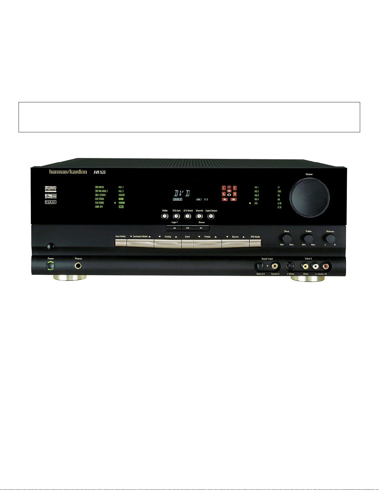
harman/kardon
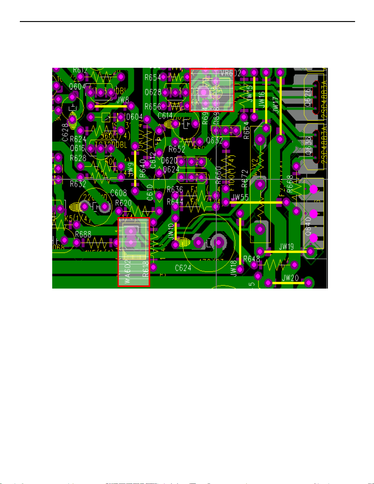
AVR520
A/V DOLBY DIGITAL RECEI VER
SERVICE MANUAL
ESD WA RNING…………………..….……….2
LEAKAGE TESTING………………...……....3
BASIC SPECIFICATIONS……………….…..4
FRONT PANEL CONTROLS………….…….5
REAR PANEL CONNECTIONS……..…..…10
REMOTE CONTROL FUNCTIONS………..1 2
TROUBLESHOOTING GUIDE…...……...…15
PROCESSOR RESET………………...…….15
UNIT EXPLODED VIEW…………..……......16
harman/kardon, Inc.
250 Crossways Park Dr.
Woodbury, New York 11797 Rev4 – 2/2004
CONTENTS
EXPLODED VIEW PARTS LIST………..….17
BLOCK DIAGRAM..…………..…..……….…18
BULLETIN HK2003-07……….…….………..19
TECH TIP HKTT2003-01……….…….…..…21
IDLE CURRENT ADJUSTMENT……………22
ELECTRICAL PARTS LIST……….…..…….25
SCHEMATICS………………….…...……..…73
WIRING DIAGRAM………….…..….…….….94
PACKAGE………………………………….…95
Page 2
AVR520
2
Some semiconductor (solid state) devices can be damaged easily by static electricity. Such components commonly are called
Electrostatically Sensitive (ES) Devices. Examples of typical ES devices are integrated circuits and some field effect transistors and
semiconductor "chip" components.
The following techniques should be used to help reduce the incidence of component damage caused by static electricity.
1. Immediately before handling any semiconductor component or semiconductor-equipped assembly, drain off any electrostatic charge on
your body by touching a known earth ground. Alternatively, obtain and wear a commercially available discharging wrist strap device,
which should be removed for potential shock reasons prior to applying power to the unit under test.
2. After removing an electrical assembly equipped with ES devices, place the assembly on a conductive surface such as aluminum foil, to
prevent electrostatic charge build-up or exposure of the assembly.
3. Use only a grounded-tip soldering iron to solder or unsolder ES devices.
harman/kardon
4. Use only an anti-static solder removal device. Some solder removal devices not classified as "anti-static" can generate electrical charges
sufficient to damage ES devices.
5. Do not use freon-propelled chemicals. These can generate electrical change sufficient to damage ES devices.
6. Do not remove a replacement ES device from its protective package until immediately before you are ready to install it. (Most replacement
ES devices are packaged with leads electrically shorted together by conductive foam, aluminum foil or comparable conductive material.)
7. Immediately before removing the protective material from the leads of a replacement ES device, touch the protective material to the
chassis or circuit assembly into which the device will be installed.
CAUTION :
8. Minimize bodily motions when handling unpackaged replacement ES devices. (Otherwise harmless motion such as the brushing together
or your clothes fabric or the lifting of your foot from a carpeted floor can generate static electricity sufficient to damage an ES devices.
Be sure no power is applied to the chassis or circuit, and observe all other safety precautions.
Each precaution in this manual should be followed during servicing.
Components identified with the IEC symbol in the parts list are special significance to safety. When replacing a component identified with
, use only the replacement parts designated, or parts with the same ratings or resistance, wattage, or voltage that are designated in the
parts list in this manual. Leakage-current or resistance measurements must be made to determine that exposed parts are acceptably
insulated from the supply circuit before retuming the product to the customer.
Page 3
AVR520
3
Before returning the unit to the user, perform the following safety checks :
1. Inspect all lead dress to make certain that
leads are not pinched or that hardware is not
lodged between the chassis and other metal
parts in the unit.
2. Be sure that any protective devices such as
nonmetallic control knobs, insulating fish-
papers, cabinet backs, adjustment and
compartment covers or shields, isolation
harman/kardon
resistor-capacity networks, mechanical
insulators, etc. Which were removed for the
servicing are properly re-installed.
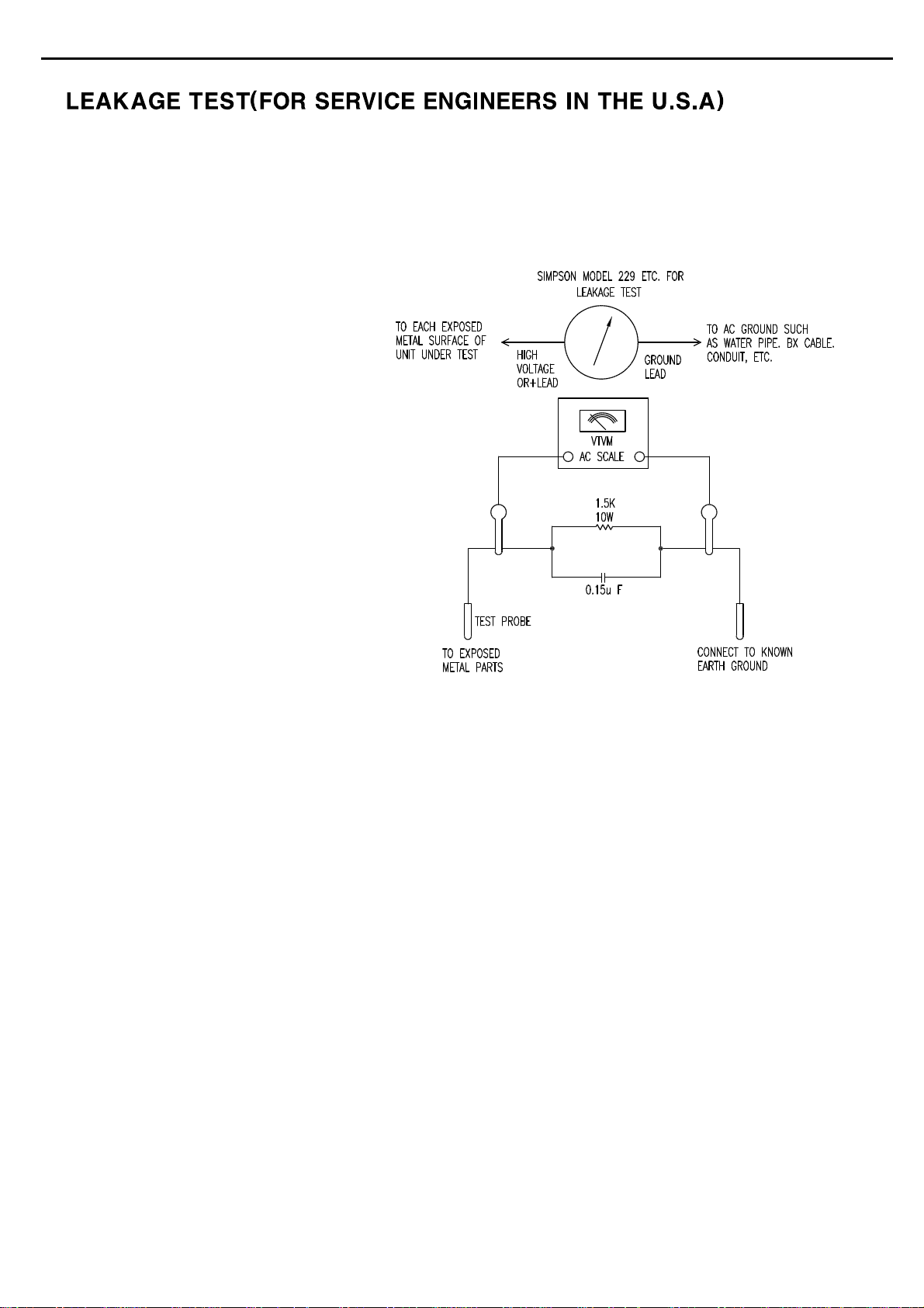
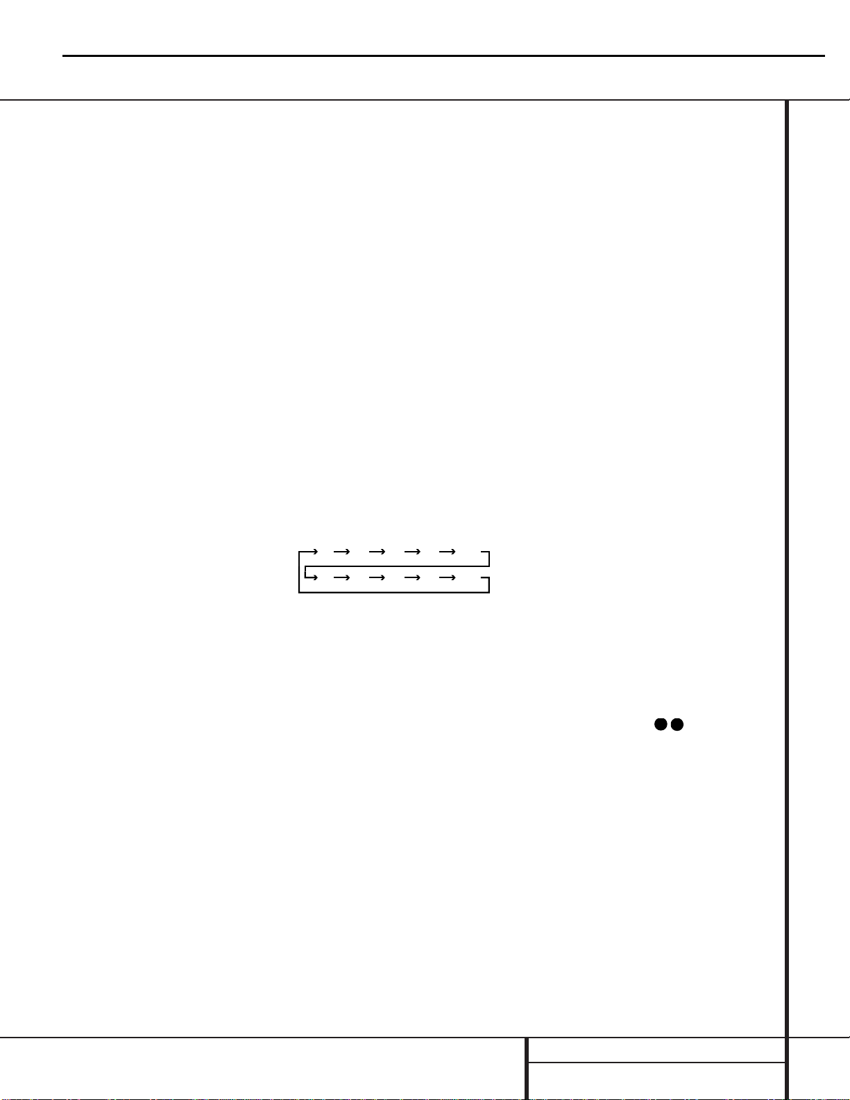
3. Be sure that no shock hazard exists ; check for leakage
current usingSimpson Model 229 Leakage Tester, standard
equipment item No. 21641, RCA Model WT540A or use
alternate method as follows : Plug the power cord directly
Into a 120 volt AC receptacle (do not use an Isolation
Transformer for this test). Using two clip leads, connect a
1500 ohms,10watt Resistor paralleledby a 0.15uFcapacitor,in series withall exposed metalcabinet parts anda known earth ground,such
as a water pipe or conduit. Use a VTVM or VOM with 1000 ohms per volt, or higher sensitivity to measure the AC voltage drop across the
resistor. (See diagram) Move the resistor connection to each exposed metal part having a return path to the chassis (antenna, metal,
cabinet, screwheads, knobsand controlshafts, escutcheon, etc.) and measurethe ACvoltage dropacross the resistor. (This testshould be
performed withthe 0.35 volt RMS or more is excessiveand indicates apotential shock hazardwhich must be corrected before returning the
unit to the owner.
Page 4

4 TECHNICAL SPECIFICATIONS
Technical Specifications
Audio Section
Stereo Mode
Continuous Average Power (FTC)
85 Watts per channel, 20Hz–20kHz,
@ < 0.07% THD, both channels driven into 8 ohms
Five-Channel Surround Modes
Power Per Individual Channel
Front L&R channels:
75 Watts per channel
@ < 0.07% THD, 20Hz–20kHz into 8 ohms
Center channel:
75 Watts @ < 0.07% THD, 20Hz–20kHz into 8 ohms
Surround channels:
75 Watts per channel
@ < 0.07% THD, 20Hz–20kHz into 8 ohms
Input Sensitivity/Impedance
Linear (High-Level) 200mV/47k ohms
Signal-to-Noise Ratio (IHF-A) 95dB
Surround System Adjacent Channel Separation
Analog Decoding 40dB
(Pro Logic II, etc.)
Dolby Digital (AC-3) 55dB
DTS 55dB
Frequency Response
@ 1W (+0dB, –3dB) 10Hz –100kHz
High Instantaneous
Current Capability (HCC) ±45 Amps
Transient Intermodulation
Distortion (TIM) Unmeasurable
Rise Time 16 µsec
Slew Rate 40V/µsec
FM T uner Section
Frequency Range 87.5–108MHz
Usable Sensitivity IHF 1.3 µV/13.2dBf
Signal-to-Noise Ratio Mono/Stereo 70/68dB
Distortion Mono/Stereo 0.2/0.3%
Stereo Separation 40dB @ 1kHz
Selectivity ±400kHz, 70dB
Image Rejection 80dB
IF Rejection 90dB
Tuner Output Level 1kHz, ±75kHz Dev 500mV
AM T uner Section
Frequency Range 520–1710kHz
Signal-to-Noise Ratio 45dB
Usable Sensitivity Loop 500µV
Distortion 1kHz, 50% Mod 0.8%
Selectivity ±10kHz, 30dB
Video Section
Television Format NTSC
Input Level/Impedance 1Vp-p/75 ohms
Output Level/Impedance 1Vp-p/75 ohms
Video Frequency Response
(Composite and S) 10Hz–8MHz (–3dB)
Video Frequency Response
(Component) 10Hz–30MHz (–3dB)
General
Power Requirement AC 120V/60Hz
Power Consumption 78W idle, 694W maximum
(2 channels driven)
Dimensions (Max)
Width 17.3 inches (440mm)
Height 6.5 inches (165mm)
Depth 17.1 inches (435mm)
Weight 35 lb (15.9 kg)
Depth measurement includes knobs, buttons and terminal connections.
Height measurement includes feet and chassis.
All features and specifications are subject to change without notice.
Harman Kardon is a registered trademark, and Power for the Digital Revolution is a trademark, of
Harman Kardon, Inc.
is a trademark of Harman International Industries, Inc. (Patent No. 5,386,478).
*Manufactured under license from Dolby Laboratories.
“Dolby,”“Pro Logic,” “Pro Logic II” and the Double-D symbol are
trademarks of Dolby Laboratories. Confidential Unpublished
Works. ©1992–1999 Dolby Laboratories, Inc. All rights reserved.
DTS, DTS Surround, DTS-ES and DTS Neo:6 are trademarks of Digital Theater Systems, Inc.
UltraStereo is a trademark of UltraStereo Corp.
VMAx is a registered trademark of Harman International Industries, Inc., and is an
implementation of Cooper Bauck Transaural Stereo under patent license.
Logic 7 is a registered trademark of Lexicon, Inc.
Crystal is a registered trademark of Cirrus Logic Corp.
HDCD system manufactured under license from Pacific Microsonics, Inc.This product is
covered by one or more of the following: In the USA: 5,479,168; 5,638,074; 5,640,161; 5,808,574;
5,838,274; 5,854,600; 5,864,311; 5,872,531; and in Australia: 669114. Other patents pending.
AVR520
harman/kardon
TM
Page 5
5 FRONT PANEL CONTROLS
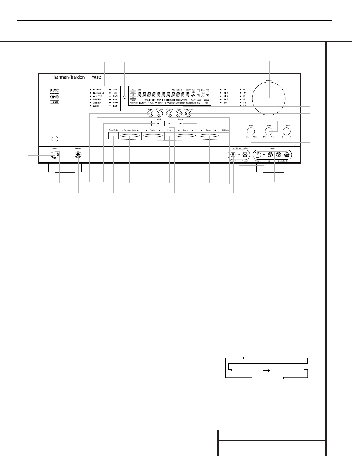
1 Main Power Switch: Press this button to
apply power to the AVR 520. When the switch
is pressed in, the unit is placed in a Standby
mode, as indicated by the amber
Power
Indicator
3 surrounding the System
Power Control
2.This button MUST be
pressed in to operate the unit. To turn the unit
off and prevent the use of the remote control,
this switch should be pressed until it pops out
from the front panel so that the word “OFF”
may be read at the top of the switch.
NOTE:This switch is normally left in the “ON”
position.
2 System Power Control:When the Main
Power Switch
1
is “ON,” press this button
to turn on the AVR 520; press it again to turn
the unit off. Note that the
Power Indicator
3
surrounding the switch will turn green
when the unit is on.
3 Power Indicator:This LED will be lit in
amber when the unit is in the Standby mode to
signal that the unit is ready to be turned on.
When the unit is in operation, the indicator will
turn green.
4 Headphone Jack:This jack may be used to
listen to the AVR 520’s output through a pair of
headphones. Be certain that the headphones
have a standard
1
/4" stereo phone plug. Note
that the main room speakers will automatically
be turned off when the headphone jack is
in use.
5 Dolby Mode Selector: Pressing this selec-
tor button cycles the AVR through the various
Dolby surround modes.The first press of the button switches the surround mode to the last
Dolby surround mode that was in use. Each subsequent press selects the next mode in the following order:
6 DTS Surround Mode Selector: Pressing
this selector button cycles the AVR through the
DTS surround modes.The first press of the button selects the last DTS surround mode that
Front Panel Controls
1 Main Power Switch
2 System Power Control
3 Power Indicator
4 Headphone Jack
5 Dolby Mode Selector
6 DTS Surround Mode Selector
7 Logic 7 Mode Selector /‹ Button
8 Tone Mode
9 Surround Mode Selector
) Tuning Selector
! Tuner Band Selector
@ Set Button
# Preset Station Selector
$ Stereo Mode Selector /› Button
% Input Source Selector
^ FM Mode Selector
& DTS Neo:6 Mode Selector
* Digital Optical 3 Input
( Input/Output Status Indicator
Ó Digital Coax 3 Jack
Ô Video 4 Input Jacks
Bass Control
Ò Balance Control
Ú Treble Control
Û Digital Select Button
Ù Channel Select Button
ı Volume Control
ˆ Input Indicators
˜ Main Information Display
¯ Remote Sensor Window
˘ Surround Mode Indicators
2
4
79
@
˘
Ú
ı
¯
Û
Ù
1
3
5
6
8
)
!
#
$
%
^
&
Ó
*
(
Ô
Ò
ˆ
˜
AVR520
harman/kardon
DOLBY PRO LOGIC II
MUSIC
DOLBY PRO LOGIC II MOVIE
DOLBY PRO LOGIC II
DOLBY 3 STEREO
EMULATION
Page 6
6 FRONT PANEL CONTROLS
Front Panel Controls
was in use. Each subsequent press selects the
next DTS mode in the following order:
7 Logic 7 Mode Selector /‹ Button:This
button has two functions: In normal use, press
it to select one of the Logic 7 modes.When an
adjustment is being made using using the
Channel Select Ù or Digital Select Û
buttons, this button may be pressed to scroll
through the available options.
8 Tone Mode: Pressing this button enables
or disables the Bass and Treble tone controls.
When the button is pressed so that the words
TONE IN appear in the
Main Information
Display
˜, the settings of the Bass and
Treble Ú controls may be used to adjust the
output signals.When the button is pressed so
that the words TONE OUT appear in the
Main
Information Display
˜, the output signal
will be “flat,” without any bass or treble alteration, no matter how the actual
Bass and
Treble Controls Ú are adjusted.
9 Surround Mode Selector: Press this but-
ton to change the surround mode by scrolling
through the list of available modes. Note that
depending on the type of input, some modes
are not always available. (See page 26 for more
information about surround modes.)
) Tuning Selector: Press the left side of the
button to tune lower-frequency stations and the
right side of the button to tune higher-frequency
stations.When a station with a strong signal
is reached, the
TUNED Indicator W will be lit
in the
Main Information Display ˜ .
To tune manually, tap the button lightly and
note that the tuner will step up one frequency
increment per button press.When the button is
held for a few seconds you will note that the
unit will quickly search the frequency band.
Release it once the fast tuning starts; the tuner
will automatically scan for the next station with
an acceptable signal and then stop.
! Tuner Band Selector: Pressing this but-
ton will automatically switch the AVR 520 to
the Tuner mode. Pressing it again will switch
between the AM and FM frequency bands. (See
page 31 for more information on the tuner.)
@ Set Button:When making choices during
the setup and configuration process, press this
button to enter the desired setting as shown
in the
Main Information Display ˜ into the
AVR 520’s memory.
# Preset Station Selector: Press this
button to scroll up or down through the list or
stations that have been entered into the preset
memory. (See page 32 for more information on
tuner programming.)
$ Stereo Mode Selector /› Button:
Pressing this selector button cycles through the
stereo modes, and it is also used to turn off all
surround processing and place the unit in a traditional two-channel Stereo mode.The first
press selects 5-Channel Stereo, the next press
selects 8-Channel Stereo, and the third press
selects “SURROUND OFF,” which is true Stereo.
% Input Source Selector: Press this button
to change the input by scrolling up or down
through the list of input sources.
^ FM Mode Selector:Press this button to
select Auto or Manual tuning.When the button
is pressed so that the
AUTO Indicator X
lights, the tuner will search for the next station
with an acceptable signal when the
Tuning
Selector
)uéis pressed. When the but-
ton is pressed so that the
AUTO Indicator X
is not lit, each press of the Tuning Selector
)uéwill increase the frequency. (See
page 31 for more information on using the
tuner.)
& DTS Neo:6 Mode Selector: Pressing this
selector button cycles the AVR through the various DTS Neo:6 modes, which extract a fivechannel surround field from two-channel program material. The first press selects the last
DTS Neo:6 surround mode that was in use, and
each subsequent press selects the next mode in
the following order:
* Digital Optical 3 Input: Connect the opti-
cal digital output of an audio or video product to
this jack. When the input is not in use, be certain
to keep the plastic cap installed to avoid dust
contamination that might degrade future
performance.
( Input/Output Status Indicator:These
LED indicators will normally light green to show
that the front panel
Video 4 A/V Ô jacks or
the
Coaxial 3 Digital Ó jacks are operating as
inputs.When either of these jacks has been configured for use as an output, the indicator will
turn red to show that the jack may be used for
recording. (See page 20 for more information on
configuring the front panel jacks as outputs,
rather than inputs.)
Ó Digital Coax 3 Jack:This jack is normally
used for connection to the output of portable
audio devices, video game consoles or other
products that have a coax digital jack. It may
also be configured as an output jack, to feed a
digital signal to a CD-R, MiniDisc or other digital recording device. (See page 20 for information on configuring the Digital Coax 3 Jack as
an output.)
Ô Video 4 Input Jacks: These audio/video
jacks may be used for temporary connection to
video games or portable audio/video products
such as camcorders and portable audio players.
Bass Control:Turn this control to modify
the low-frequency output of the left/right channels by as much as ±10dB. Set this control to a
suitable position for your taste or room acoustics.
Ò Balance Control:Turn this control to
change the relative volume for the front
left/right channels.
NOTE: For proper operation of the surround
modes, this control should be at the midpoint,
or “12 o’clock”, position.
Ú Treble Control: Turn this control to modify
the high-frequency output of the left/right channels by as much as ±10dB. Set this control to a
suitable position for your taste or room acoustics.
Û Digital Select Button:When playing a
source that has a digital output, press this
button to select between the
Optical *
and Coaxial Ó Digital inputs. (See
page 29 for more information on digital audio.)
Ù Channel Select Button: Press this button
to begin the process of trimming the channel
output levels using an external audio source.
(For more information on output level trim
adjustment, see page 32.)
AVR520
harman/kardon
DTS-ES 6.1 DISCRETE
DTS-ES 6.1 MATRIX DTS 5.1
DTS Neo:6 MUSIC
DTS Neo:6
MOVIES
DTS Neo:6
EMULATION
34
33
Page 7

7 FRONT PANEL CONTROLS
Front Panel Controls
ı Volume Control:Turn this knob clockwise
to increase the volume, counterclockwise to
decrease the volume. If the AVR 520 is muted,
adjusting volume control will automatically
release the unit from the silenced condition.
ˆ Input Indicators: A green LED will light
to the left of the input that is currently the
input source for the AVR 520.
˜ Main Information Display:This display
delivers messages and status indications to
help you operate the receiver. (See pages 8 & 9
for a complete explanation of the Information
Display.)
¯ Remote Sensor Window:The sensor
behind this window receives infrared signals
from the remote control. Aim the remote at this
area and do not block or cover it unless an
external remote sensor is installed.
˘ Surround Mode Indicators: A green LED
will light in front of the surround mode that is
currently in use.
AVR520
harman/kardon
Page 8
8 FRONT PANEL INFORMATION DISPLAY
Front Panel Information Display
A
B
D
E
N
O
K
M
L
T
U
S
R
P
Z
Y
X
W
V
F
H
I
J
C
G
Q
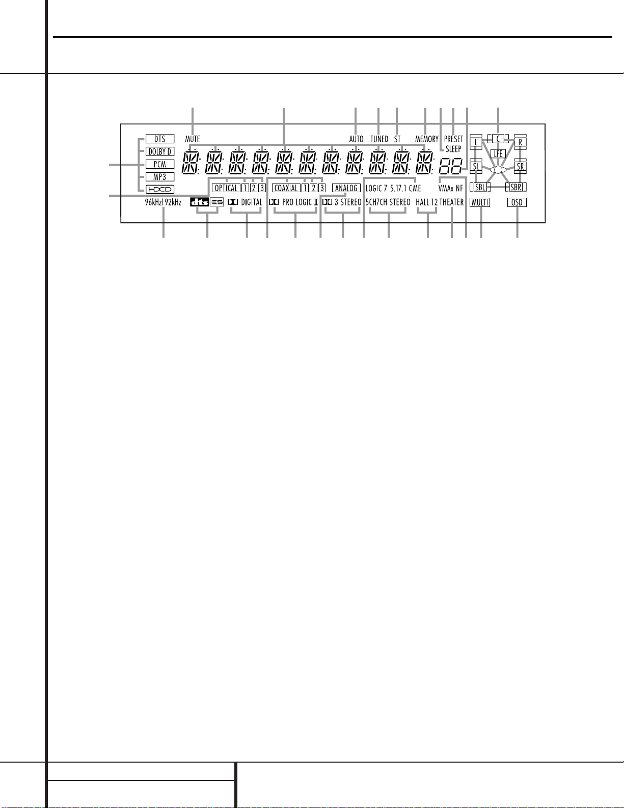
A Bitstream Indicators
B Optical Source Indicators
C Sample Rate Indicators
D DTS Mode Indicator
E Dolby Digital Indicator
F Coaxial Source Indicators
G Dolby Pro Logic II Indicator
H Analog Input Indicator
I Dolby 3 Stereo Indicator
J Logic 7 Mode Indicators
K 5-Channel/7-Channel Stereo Indicators
L Hall Mode Indicators
M Theater Mode Indicator
N VMAx Mode Indicators
O Multiroom Indicator
P OSD Indicator
Q Speaker/Channel Input Indicators
R Preset Number/Sleep Timer
S Preset Indicator
T Sleep Indicator
U Memory Indicator
V Stereo Indicator
W Tuned Indicator
X Auto Indicator
Y Main Information Display
Z Mute Indicator
A Bitstream Indicators: When the input is a
digital source, one of these indicators will light to
display the specific type of data signal in use.
B Optical Source Indicators:These indicators light to show when an Optical Digital Input
has been selected.
C Sample Rate Indicators: One of these
indicators will light when 96kHz or 192kHz
source material is in use.
D DTS Mode Indicator:This indicator lights
when a DTS-encoded source is playing.
E Dolby Digital Indicator:This indicator
lights when a Dolby Digital source is being
played.
F Coaxial Source Indicators:These indicators light to show when a Coaxial Digital Input
has been selected.
G Dolby Pro Logic II Indicator:This indicator lights when the Dolby Pro Logic II mode has
been selected.
NOTE:
It is possible to see the Dolby Pro Logic II
indicator lit simultaneously with the Dolby
Digital indicator, even though the Dolby Digital
surround mode has been selected. This is due to
the specifications for Dolby Digital processing,
which require that the Dolby Pro Logic II mode
be applied when a 2-channel Dolby signal is
detected. If you desire 5.1-channel audio, check
the audio settings in the menus for your DVD
disc to make sure that a 5.1-channel Dolby
Digital soundtrack has been selected.
H Analog Input Indicator: This indicator
lights when an analog input source has been
selected.
I Dolby 3 Stereo Indicator:This indicator
lights when the Dolby 3 Stereo mode has been
selected.
J Logic 7 Mode Indicators:These indicators light to indicate that one of the Logic 7
modes is in use.Along with the main Logic 7
indicator, either 5.1 or 7.1 will light to indicate
the selected speaker configuration. One of the
three letters to the far right of this segment will
light to show which version of Logic 7 processing is in use: C for the Cinema mode, M for the
Music mode and E for the Enhanced mode used
with two-channel sources.The Enhanced mode
in only available with the 5.1 speaker configuration. (See page 26 for a description of the
Logic 7 modes.)
K 5-Channel/7-Channel Stereo
Indicators:
These indicators light to show if
the 5-Channel or 7-Channel Stereo mode has
been selected.
L Hall Mode Indicators:These indicators
light when one of the Hall modes has been
selected.
M Theater Mode Indicator: This indicator
lights to show that the Theater mode is in use.
N VMAx Mode Indicators: One of these
indicators lights when the VMAx mode is in
use.
VMAx F appears when the Far Field
VMAx mode is selected;
VMAx N appears
when the Near Field VMAx mode is selected.
(See page 27 for a description of the VMAx
modes.)
O Multiroom Indicator:This indicator lights
when the multiroom system is active. Note that
it will remain lit when the multiroom system is
in use even though the main room system is in
the Standby mode and all other indicators are
dark. (See page 36 for more information on the
Multiroom system.)
P OSD Indicator:When the OSD system is in
use, this indicator lights to remind you that the
other indicators in this display do not function
when the On-Screen Display is being used.
Q Speaker/Channel Input Indicators:These
indicators are multipurpose, indicating either the
speaker type selected for each channel or the
incoming data-signal configuration.The left,
center, right, right surround and left surround
speaker indicators are composed of three boxes,
while the subwoofer is a single box. The center
box lights when a “Small” speaker is selected,
and the two outer boxes light when “Large”
speakers are selected.When none of the boxes
are lit for the center, surround or subwoofer
channels, no speaker has been selected for one
of those positions. (See page 22 for more infor-
AVR520
harman/kardon
Page 9

9 FRONT PANEL INFORMATION DISPLAY
Front Panel Information Display
mation on configuring speakers.) The letters inside
each of the center boxes display the active input
channels. For standard analog inputs, only the L
and R will light, indicating a stereo input.When a
digital source is playing, the indicators will light to
display the channels being received at the digital
input. When the letters flash, the digital input has
been interrupted. (See pages 23 & 30 for more
information on the Channel Indicators.)
R Preset Number/Sleep Timer: When the
tuner is in use, these numbers indicate the specific preset memory location in use. (See page 32
for more information on preset stations.) When
the Sleep function is in use, these numbers show
how many minutes remain before the unit goes
into the Standby mode.
S Preset Indicator:This indicator lights when
the tuner is in use to show that the
Preset
Number/Sleep Timer
R is showing the station’s preset memory number. (See page 32 for
more information on tuner presets.)
T Sleep Indicator:This indicator lights when
the Sleep function is in use.The numbers in the
Preset Number/Sleep Timer R indicator will
show the minutes remaining before the AVR 520
goes into the Standby mode. (See page 28 for
more information on the Sleep function.)
U
Memory Indicator: This indicator flashes
when entering presets and other information
into the tuner’s memory.
V Stereo Indicator:This indicator lights when
an FM station is being tuned in stereo.
W
Tuned Indicator:
This indicator lights when a
station is being received with sufficient signal
strength to provide acceptable listening quality.
X Auto Indicator: This indicator lights when
the tuner’s Auto mode is in use.
Y Main Information Display:This display
shows messages relating to the status, input
source, surround mode, tuner, volume level or
other aspects of the AVR 520’s operation.
Z Mute Indicator:This indicator lights to
remind you that the AVR 520’s output has been
silenced by pressing the
Mute Button
˚
.
Press the Mute button again to return to the
previously selected output level.
AVR520
43
harman/kardon
Page 10
10 REAR PANEL CONNECTIONS
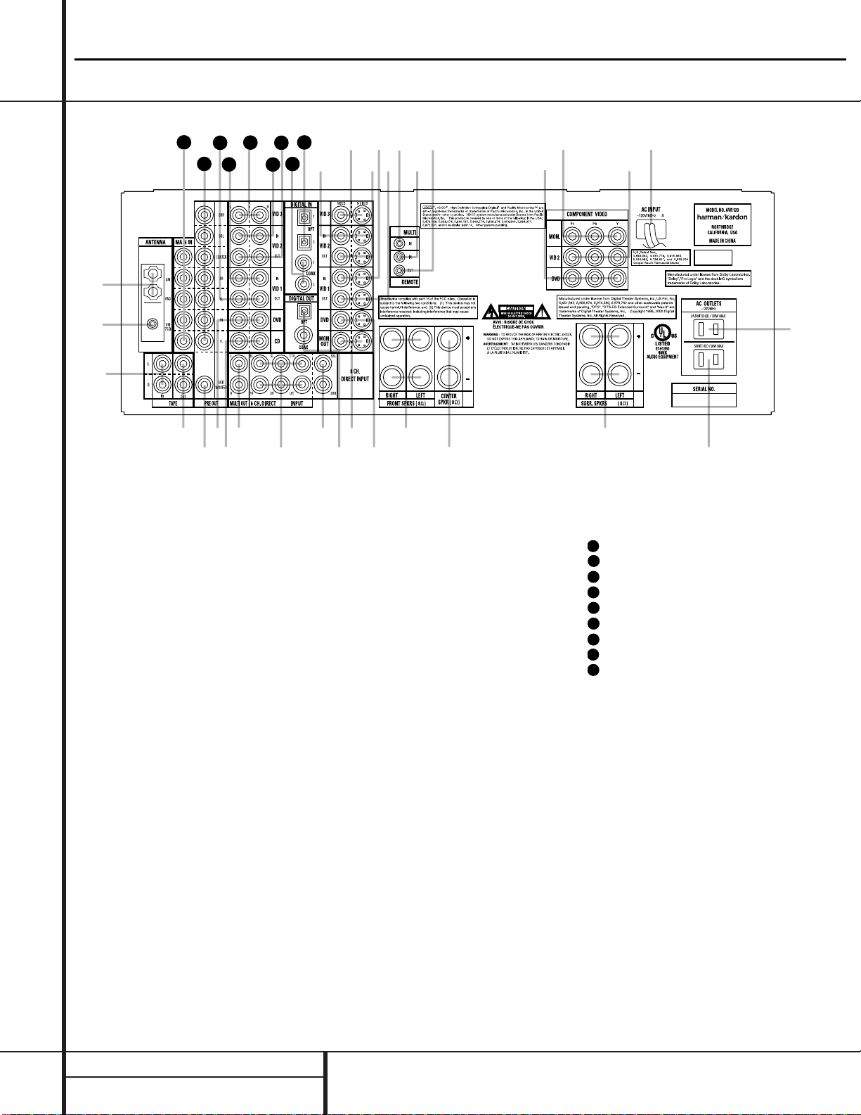
¡ AM Antenna:Connect the AM loop antenna
supplied with the receiver to these terminals. If an
external AM antenna is used, make connections
to the
AM and GND terminals in accordance
with the instructions supplied with the antenna.
™ FM Antenna: Connect the supplied indoor or
an optional external FM antenna to this terminal.
£ Tape Inputs: Connect these jacks to the
PLAY/OUT jacks of an audio recorder.
¢ Tape Outputs: Connect these jacks to the
RECORD/INPUT jacks of an audio recorder.
∞ Subwoofer Output: Connect this jack to
the line-level input of a powered subwoofer. If
an external subwoofer amplifier is used, connect this jack to the subwoofer amplifier input.
§ DVD Audio Inputs: Connect these jacks
to the analog audio jacks on a DVD or other
video source.
¶ CD Inputs: Connect these jacks to the out-
put of a compact disc player or CD changer.
• Multiroom Outputs: Connect these jacks
to an optional audio power amplifier to listen
to the source selected by the mulitroom system
in a remote room.
ª 6-Channel Direct Inputs:When an
optional, external processor or playback device
with 5.1 audio capability is in use, connect the
player's output jacks here.
NOTE:To assist in making the correct connections for multichannel input output and speaker
connections, all connection jacks and terminals
have been color coded in conformance with the
latest CEA standards as follows:
Front Left: White
Front Right: Red
Center: Green
Surround Left: Blue
Surround Right: Gray
Surround Back Left: Brown
Surround Back Right: Tan
Subwoofer: Purple
Digital Audio: Orange
Composite Video: Yellow
Component Video “Y”: Green
Component Video “Pr”: Red
Component Video “Pb”: Blue
‚ 8-Channel Direct Inputs: When an
option, external processor or playback device
with 6.1 or 7. 1 audio capability is in use, connect the Surround Back Left and Surround Back
Right channel outputs of the player to these
input jacks.
⁄ Digital Audio Outputs: Connect these
jacks to the matching digital input connector
on a digital recorder such as a CD-R or
MiniDisc recorder.
Rear Panel Connections
∞
ª
‚
‹
fi
fl
°
·
a
b
c
d
e
f
gi
j
‡
§
31
32
36
h
k
35
34
39
38
37
33
•
¶
¤
⁄
›
¡
™
£
¢
¡ AM Antenna
™ FM Antenna
£ Tape Inputs
¢ Tape Outputs
∞ Subwoofer Output
§ DVD Audio Inputs
¶ CD Inputs
• Multiroom Outputs
ª 6-Channel Direct Inputs
‚ 8 Channel Direct Inputs
⁄ Digital Audio Outputs
¤ Video Monitor Outputs
‹ DVD Video Inputs
› Front Speaker Outputs
fi Center Speaker Outputs
fl Surround Speaker Outputs
‡ Switched AC Accessory Outlet
° Unswitched AC Accessory Outlet
· AC Power Cord
a Video 2 Component Video Inputs
b Component Video Outputs
c DVD Component Video Inputs
d Remote IR Output
e Remote IR Input
f Multiroom IR Input
g Video 1 Video Outputs
h Video 1 Video Inputs
i Video 2 Video Outputs
j Video 3 Video Inputs
k Video 2 Video Inputs
Optical Digital Inputs
Coaxial Digital Inputs
Video 2 Audio Outputs
Video 2 Audio Inputs
Video 3 Audio Inputs
Video 1 Audio Inputs
Video 1 Audio Outputs
Preamp Outputs
Amplifier Inputs
AVR520
harman/kardon
31
32
33
34
35
36
37
38
39
Page 11
11 REAR PANEL CONNECTIONS
Rear Panel Connections
¤ Video Monitor Outputs: Connect this
jack to the composite or S-Video input of a TV
monitor or video projector to view the on-screen
menus and the output of any standard video
source selected by the receiver’s video switcher.
‹ DVDVideo Inputs: Connect these jacks to
the composite or S-Video output jacks on a
DVD or other video source.
› Front Speaker Outputs: Connect these
outputs to the matching + or – terminals on
your left and right speakers.When making
speaker connections always make certain to
maintain correct polarity by connecting the red
(+) terminals on the AVR 520 to the red (+) terminals on the speakers and the black (–) terminals on the AVR 520 to the black (–) terminals
on the speakers. See page 16 for more information on speaker polarity.
fi Center Speaker Outputs: Connect these
outputs to the matching + and – terminals on
your center channel speaker. In conformance
with the new CEA color code specification, the
Green Terminal is the positive, or "+" terminal
that should be connected to the red (+) terminal on speakers with the older color coding.
Connect the black (–) terminal on the AVR to
the black negative (–) terminal on your speaker.
(See page 16 for more information on speaker
polarity.)
fl Surround Speaker Outputs: Connect
these outputs to the matching + and – terminals on your surround channel speakers. In conformance with the new CEA color code specification, the Blue terminal is the positive, or "+"
terminal that should be connected to the red
(+) terminal on the Surround Left speaker with
older color coding, while the Gray terminal
should be connected to the red (+) terminal on
the Surround Right speaker with the older color
coding. Connect the black (–) terminal on the
AVR to the matching black negative (–) terminals for each surround speaker. (See page 17
for more information on speaker polarity.)
‡ Switched AC Accessory Outlet: This
outlet may be used to power any device you
wish to have turned on when the AVR 520 is
turned on with the
System Power Control
Button
2.
° Unswitched AC Accessory Outlet: This
outlet may be used to power any AC device.
The power will remain on at this outlet regardless of whether the AVR 520 is on or off.
NOTE:The total power consumption of all
devices connected to the accessory outlets
should not exceed 100 watts.
· AC Pow er Cord: Connect the AC plug to
an unswitched AC wall output.
a Video 2 Component Video Inputs:
Connect the Y/Pr/Pb component video outputs
of an HDTV Set-top convertor, satellite receiver,
or other video source device with component
video outputs to these jacks.
b Component Video Outputs: Connect
these outputs to the component video inputs of
a video projector or monitor. When a source
connected to one of the two
Component
Video Inputs
ac is selected the signal will
be sent to these jacks.
c DVD Component Video Inputs: Connect
the Y/Pr/Pb component video outputs of a DVD
player to these jacks.
d Remote IR Output:This connection permits the IR sensor in the receiver to serve other
remote controlled devices. Connect this jack to
the “IR IN” jack on Harman Kardon (or other
compatible) equipment.
e Remote IR Input: If the AVR 520’s front-
panel IR sensor is blocked due to cabinet
doors or other obstructions, an external IR
sensor may be used. Connect the output of
the sensor to this jack.
f Multiroom IR Input:Connect the output of
an IR sensor in a remote room to this jack to
operate the AVR 520’s multiroom control system.
g Video 1 Video Outputs: Connect these
jacks to the
RECORD/INPUT composite or
S-Video jack on a VCR.
h Video 1 Video Inputs: Connect these
jacks to the
PLAY/OUT composite or S-Video
jacks on a VCR or other video source.
i Video 2 Video Outputs: Connect these
jacks to the
RECORD/INPUT composite or
S-Video jacks on a VCR.
j Video 3 Video Inputs: Connect these
jacks to the
PLAY/OUT composite or S-Video
jacks on a VCR or other video source.
k Video 2 Video Inputs: Connect these
jacks to the
PLAY/OUT composite or S-Video
jacks on a VCR or other video source.
Optical Digital Inputs: Connect the opti-
cal digital output from a DVD player, HDTV
receiver, the S/P-DIF output of a compatible
computer sound card playing MP3 files or
streams, LD player or CD player to these jacks.
The signal may be either a Dolby Digital signal,
a DTS signal or a standard PCM digital source.
Coaxial Digital Inputs: Connect the coax
digital output from a DVD player, HDTV receiver,
the S/P-DIF output of a compatible computer
sound card playing MP3 files or streams, LD player
or CD player to these jacks.The signal may be
either a Dolby Digital signal, DTS signal or a standard PCM digital source. Do not connect the RF
digital output of an LD player to these jacks.
Video 2 Audio Outputs:Connect these
jacks to the
RECORD/INPUT audio jacks on a
VCR or other video source.
Video 2 Audio Inputs:Connect these
jacks to the
PLAY/OUT audio jacks on a VCR
or other video source.
Video 3 Audio Inputs:Connect these
jacks to the
PLAY/OUT audio jacks on a VCR
or other video source.
Video 1 Audio Inputs:Connect these
jacks to the
PLAY/OUT audio jacks on a VCR
or other video source.
Video 1 Audio Outputs:Connect these
jacks to the
RECORD/INPUT audio jacks on a
VCR.
Preamp Outputs: When the jumper pins
that link the
Amplifier Inputs with these
outputs are removed, these jacks may be connected to an external power amplifier.
Amplifier Inputs: When the jumper pins
that link the
Preamp Outputs with these
inputs are removed, these jacks may be used to
connect an external source or the AVR 520’s
multiroom system to the internal amplifiers.
AVR520
harman/kardon
31
32
33
34
35
36
37
38
39
39
38
Page 12
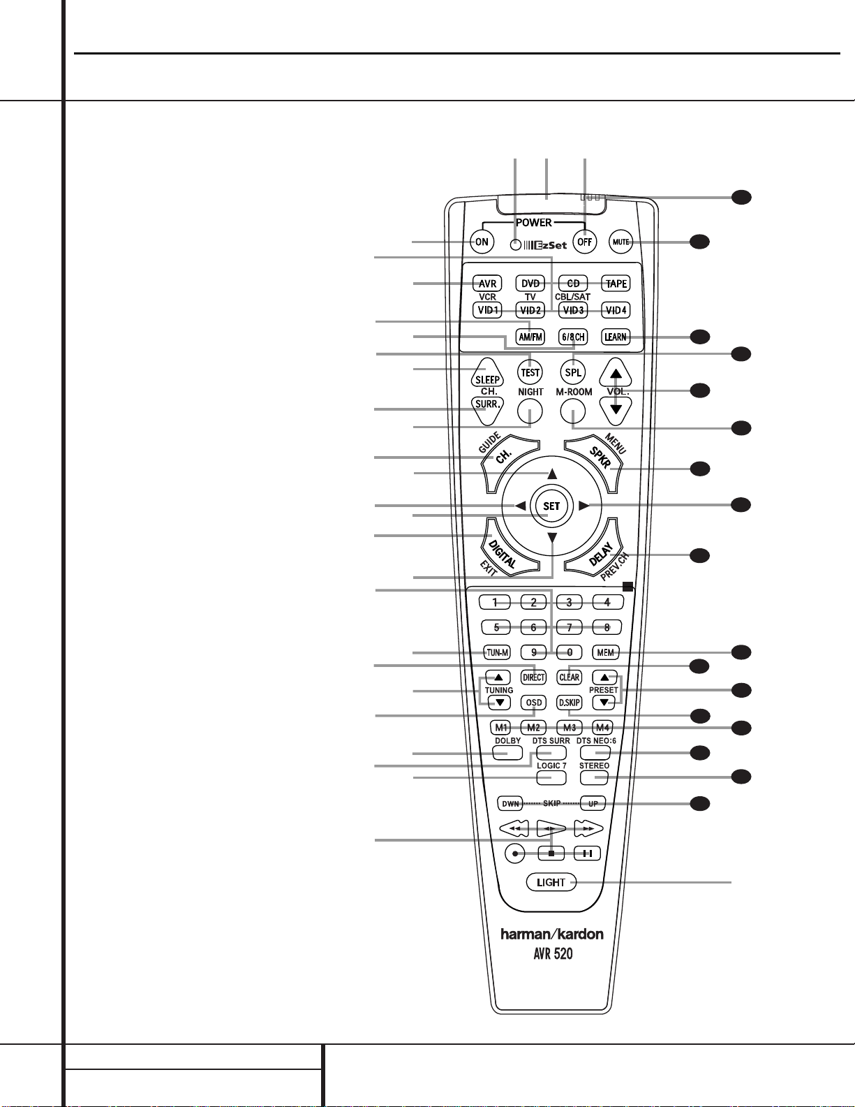
12 MAIN REMOTE CONTROL FUNCTIONS
●
●
●
●
●
●
●
●
●
●
●
●
●
●
●
●
●
a
bc
d
e
g
h
i
j
l
n
o
`
32
30
29
37
36
35
34
33
31
38
z
x
39
40
41
42
43
44
f
m
k
p
q
n
r
s
t
u
v
w
y
28
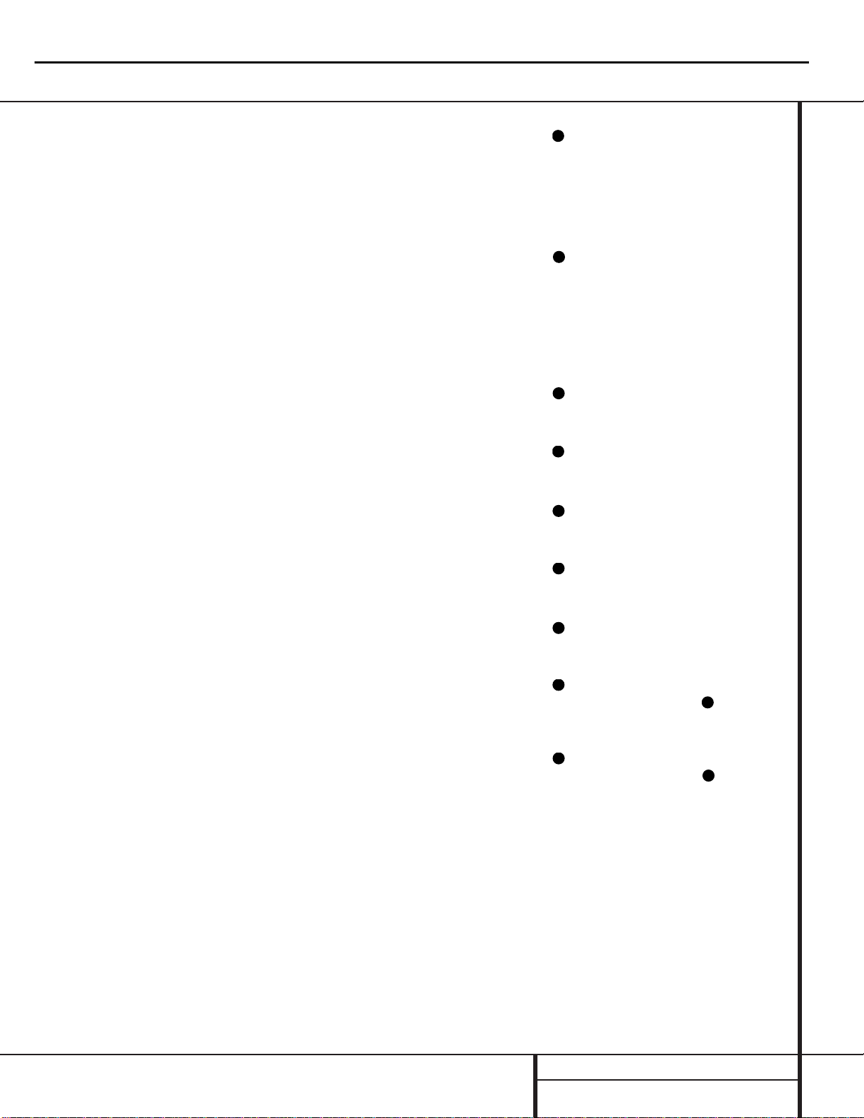
a Power Off Button
b IR Transmitter Window
c Program/SPL Indicator
d Power On Button
e Input Selectors
f AVR Selector
g AM/FM Tuner Select
h 6-Channel/8-Channel Direct Input
i Test Button
j Sleep Button
k Surround Mode Selector
l Night Mode
m Channel Select Button
n
⁄/¤
Buttons
o‹Button
p Set Button
q Digital Select
r Numeric Keys
s Tuner Mode
t Direct Button
u Tuning Up/Down
v OSD Button
w Dolby Mode Select Button
x DTS Digital Mode Selector
y Logic 7 Mode Select Button
z Transport Controls
`
Light Button
28
Skip Up/Down Button
29
Stereo Mode Select Button
30
DTS Neo:6 Mode Select
31
Macro Buttons
32
Disc Skip Button
33
Preset Up/Down
34
Clear Button
35
Memory Button
36
Delay/Prev. Ch.
37
›
Button
38
Speaker Select
39
Multiroom
40
Volume Up/Down
41
SPL Indicator Select
42 Learn Button
43
Mute
44
EzSet Sensor Microphone
NOTE:The function names shown here are each button’s feature when used with the AVR 520. Most buttons
have additional functions when used with other devices.
See pages 42–43 for a list of these functions.
Main Remote Control Functions
AVR520
harman/kardon
Page 13
13 MAIN REMOTE CONTROL FUNCTIONS
Main Remote Control Functions
IMPORTANT NOTE:The AVR 520’s remote
may be programmed to control up to eight
devices, including the AVR 520. Before using the
remote, it is important to remember to press the
Input Selector Button e that corresponds
to the unit you wish to operate. In addition, the
AVR 520’s remote is shipped from the factory to
operate the AVR 520 and most Harman Kardon
CD or DVD players and cassette decks.The
remote is also capable of operating a wide variety of other products using the control codes
that are part of the remote. Before using the
remote with other products, follow the instructions on pages 37–41 to program the proper
codes for the products in your system.
It is also important to remember that many of
the buttons on the remote take on different
functions, depending on the product selected
using the Device Control Selectors.The descriptions shown here primarily detail the functions
of the remote when it is used to operate the
AVR 520. (See page 39 for information about
alternate functions for the remote’s buttons.)
a Power Off Button: Press this button to
place the AVR 520 or a selected device in the
Standby mode. Note that this will turn off the
main room functions, but if the Multiroom system is activated, it will continue to function.
b IR T ransmitter W indow:Point this window towards the AVR 520 when pressing buttons
on the remote to make certain that infrared commands are properly received.
c Program/SPL Indicator:This three-color
indicator is used to guide you through the
process of programming the remote or learning
commands from a remote into the AVR 520’s
remote code memory and it is also used as a
level indicator when using the remote’s EzSet
capabilities. (See page 24 for more information
on setting output levels, and see page 37 for
information on programming the remote.)
d Power On Button: Press this button to
turn on the power to a device selected by pressing one of the
Input Selectors e.
e Input Selectors: Pressing one of these
buttons will perform three actions at the same
time. First, if the AVR 520 is not turned on, this
will power up the unit. Next, it will select the
source shown on the button as the input to the
AVR 520. Finally, it will change the remote control so that it controls the device selected. After
pressing one of these buttons you must press
the
AVR Selector Button f again to oper-
ate the AVR 520’s functions with the remote.
f AVR Selector: Pressing this button will
switch the remote so that it will operate the
AVR 520’s functions. If the AVR 520 is in the
Standby mode, it will also turn the AVR 520 on.
g AM/FM Tuner Select: Press this button to
select the AVR 520’s tuner as the listening
choice. Pressing this button when the tuner is
already in use will select between the AM and
FM bands.
h 6-Channel/8 Channel Direct Input:
Press this button to select the device connected
to the
6-Channel Direct Inputs 9 or the 8-
Channel Direct Inputs
9). (See page 33
for more information.)
i Test Button: Press this button to begin
the sequence used to calibrate the AVR 520’s
output levels. (See page 24 for more information
on calibrating the AVR 520.)
j Sleep Button: Press this button to place
the unit in the Sleep mode.After the time
shown in the display, the AVR 520 will automatically go into the Standby mode. Each press
of the button changes the time until turn-off in
the following order:
Note that this button is also used to change
channels on your TV when the TV is selected.
When the AVR 520 remote is being programmed
with the codes to operate another device, this
button is also used in the “Auto Search” process.
(See page 37 for more information on programming the remote.)
k Surround Mode Selector: Press this
button to begin the process of changing the
surround mode.After the button has been
pressed, use the
⁄/¤
Buttons n to select
the desired surround mode. (See page 28 for
more information.) Note that this button is also
used to tune channels when the TV is selected
using the device
Input Selector e.
When the AVR 520 remote is being programmed with the codes of another device, this
button is also used in the “Auto Search”
process. (See page 37 for more information on
programming the remote.)
l Night Mode: Press this button to activate
the Night mode.This mode is available in specially encoded digital sources, and it preserves
dialog (center channel) intelligibility at low
volume levels.
m Channel Select Button:This button is
used to start the process of setting the AVR 520’s
output levels to an external source. Once this button is pressed, use the
⁄/¤
Buttons n to
select the channel being adjusted, then press the
Set Buttonp, followed by the
⁄/¤
Buttons
n again, to change the level setting. (See page
32 for more information.)
n
⁄/¤
Buttons:These multipurpose but-
tons are used to change or scroll through items
in the on-screen menus, make configuration
settings such as digital inputs or delay timing,
or to select surround modes.When changing a
setting, first press the button for the function or
setting to be changed (e.g., press the
Surround Mode Selector k to select a
soundfield mode or the
Digital Select Button
q to change a digital input) and then press
one of these buttons to scroll through the list
of options or to increase or decrease a setting.
The sections in this manual describing the individual features and functions contain specific
information on using these buttons for each
application.
o
‹
Button:This button is used to change
the menu selection or setting during some of
the setup procedures for the AVR 520.
p Set Button:This button is used to enter
settings into the AVR 520’s memory. It is also
used in the setup procedures for delay time,
speaker configuration and channel output level
adjustment.
q Digital Select: Press this button to assign
one of the digital inputs
*Ó to a
source. (See page 29 for more information on
using digital inputs.)
r Numeric Keys:These buttons serve as a
ten-button numeric keypad to enter tuner preset
positions.They are also used to select channel
numbers when TV, Cable or SAT has been
selected on the remote, or to select track numbers on a CD, DVD or LD player, depending on
how the remote has been programmed.
s Tuner Mode: Press this button when the
tuner is in use to select between automatic
tuning and manual tuning. When the button is
pressed so that the
AUTO Indicator X goes
out, pressing the
Tuning Buttons u)
≠
will move the frequency up or down in singlestep increments.When the FM band is in use,
pressing this button when a station’s signal is
AVR520
harman/kardon
90
min80min70min60min50min
30
40
min20min10min
min
OFF
31
32
Page 14
weak will change to monaural reception. (See
page 31 for more information.)
t Direct Button: Press this button when
the tuner is in use to start the sequence for
direct entry of a station’s frequency. After pressing the button, simply press the proper
Numeric Keys r to select a station. (See
page 32 for more information on the tuner.)
u Tuning Up/Down:When the tuner is in
use, these buttons will tune up or down through
the selected frequency band. If the
Tuner Mode
Button
s^ has been pressed so that the
AUTO Indicator X is illuminated, pressing and
holding either of the buttons for three seconds
will cause the tuner to seek the next station with
acceptable signal strength for quality reception.
When the
AUTO Indicator X is NOT illumi-
nated, pressing these buttons will tune stations
in single-step increments. (See page 31 for more
information.)
v OSD Button: Press this button to activate
the On-Screen Display (OSD) system used to set
up or adjust the AVR 520’s parameters.
w Dolby Mode Selector:This button is
used to select from among the available Dolby
Surround processing modes. Each press of this
button will select one of the Dolby Pro Logic II
modes or Dolby 3 Stereo.When a Dolby Digital
encoded source is in use, the Dolby Digital mode
may also be selected. (See page 26 for the available Dolby surround mode options.)
x DTS Digital Mode Selector:When a
DTS-encoded digital source is selected, each
press of this button will scroll thorugh the available DTS modes.The specific choice of modes
will vary according to whether or not the source
material contains DTS-ES 6.1 Discrete encoding.
When a DTS source is not in use, this button has
no function. (See page 40 for the available DTS
Digital options.)
y Logic 7 Selector: Press this button to
select from among the available Logic 7 surround modes. (See page 26 for the available
Logic 7 options.)
z Transport Controls: These buttons do
not have any functions for the AVR 520, but
they may be programmed for the forward/
reverse play operation of a wide variety of CD
or DVD players, and audio or video cassette
recorders. (See page 40 for more information.)
` Light Button: Press this button to acti-
vate the remote’s backlight for ease of use in
darkened rooms.
Skip Up/Down Buttons: These buttons
do not have a direct function with the AVR 520,
but when used with a compatibly programmed
CD or DVD changer they will change the disc
currently being played in the changer.
Macro Buttons: Press these buttons
to store or recall a “Macro”, which is a
preprogrammed sequence of commands
stored in the remote. (See page 38 for more
information on storing and recalling macros.)
Disc Skip Buttons:This button has no
direct function for the AVR 520 but is most
often used to change to the next disc in a CD
or DVD player when the remote is programmed
for that type of device. (See page 37 for more
information on using the remote with products
other than the AVR 520.)
Preset Up/Down:When the tuner is
in use, press these buttons to scroll through the
stations programmed into the AVR 520’s memory.When some source devices, such as CD
players,VCRs and cassette decks, are selected
using the device
Input Selectors e, these
buttons may function as Chapter Step or Track
Advance.
Clear Button: Press this button to clear
incorrect entries when using the remote to
directly enter a radio station’s frequency.
Memory Button: Press this button to
enter a radio station into the AVR 520’s preset
memory. Once the
MEMORYIndicator U
flashes, you have five seconds to enter a preset
memory location using the
Numeric Keys
r. (See page 31 for more information.)
Delay/Prev Ch.: Press this button to
begin the process for setting the delay times
used by the AVR 520 when processing surround
sound. After pressing this button, the delay
times are entered by pressing the
Set Button
p and then using the
⁄/¤
Buttons n to
change the setting. Press the
Set Button p
again to complete the process. (See page 23 for
more information.)
›
Button: Press this button to change a
setting or selection when configuring many of the
AVR 520’s settings.
Speaker Select: Press this button
to begin the process of configuring the
AVR 520’s bass management system for use
with the type of speakers used in your system.
Once the button has been pressed, use the
⁄/¤
Buttons n to select the channel you
wish to set up. Press the
Set Button p and
then select another channel to configure.
When all adjustments have been completed,
press the
Set Button p twice to exit the
settings and return to normal operation. (See
page 22 for more information.)
Multiroom: Press this button to activate
the multiroom system or to begin the process of
changing the input or volume level for the second zone. (See page 36 for more information on
the Multiroom system.)
Volume Up/Down: Press these buttons to
raise or lower the system volume.
SPL Indicator Select:This button acti-
vates the AVR 520’s EzSet function to quickly
and accurately calibrate the AVR 520’s output
levels. Press and hold the button for three seconds and then release it. Note that the test
tone will begin circulating, and the
Program/SPL Indicator c will change
colors. During this sequence, EzSet will automatically adjust the output levels for all
channels until they are equal, as shown by the
Program/SPL Indicator lighting green for
each channel. Press this button again when the
adjustment is complete to turn off the test
tone. (See page 24 for more information on
EzSet.)
Learn Button: Press this button to begin
the process of “learning” the codes from another
product’s remote into the AVR 520’s remote. (See
page 37 for more information on using the
remote’s learning function.)
Mute: Press this button to momentarily
silence the AVR 520 or TV set being controlled,
depending on which device has been selected.
When the AVR 520 remote is being programmed
to operate another device, this button is pressed
with the
Input Selector Button e to begin
the programming process. (See page 37 for
more information on programming the remote.)
EzSetSensor Microphone: The sensor
microphone for the EzSet microphone is behind
these slots.When using the remote to calibrate
speaker output levels using EzSet, be sure that
you do not hold the remote in a way that covers these slots. (See page 24 for more information on using EzSet.)
14 MAIN REMOTE CONTROL FUNCTIONS
Main Remote Control Functions
AVR520
harman/kardon
28
31
32
33
34
35
36
37
38
39
40
41
42
43
44
Page 15

SYMPTOM CAUSE SOLUTION
Unit does not function when Main • No AC Power • Make certain AC power cord is plugged into
Power Switch is pushed a live outlet
• Check to see whether outlet is switch-controlled
Display lights, but no sound • Intermittent input connections • Make certain that all input and speaker connections
or picture •
Mute is on are secure
• Volume control is down • Press
Mute button
• Turn up volume control
Unit turns on, but front panel • Display brightness is turned off • Follow the instructions in the Display Brightness section
display does not light up on page 35 so that the display is set to VFD FULL
No sound from any speaker; • Amplifier is in protection mode • Check speaker wire connections for shorts at receiver and
light around power switch is red due to possible short speaker ends
• Amplifier is in protection mode • Contact your local Harman Kardon service depot
due to internal problems
No sound from surround or • Incorrect surround mode • Select a mode other than Stereo
center speakers • Input is monaural • There is no surround information from mono sources
• Incorrect configuration • Check speaker mode configuration
• Stereo or Mono program material • The surround decoder may not create center- or rear-channel
information from nonencoded programs
Unit does not respond to • Weak batteries in remote • Change remote batteries
remote commands • Wrong device selected • Press the AVR selector
• Remote sensor is obscured • Make certain front panel sensor is visible to remote
or connect remote sensor
Intermittent buzzing in tuner • Local interference • Move unit or antenna away from computers, fluorescent
lights, motors or other electrical appliances
Letters flash in the channel indicator • Digital audio feed paused • Resume play for DVD
display and digital audio stops • Check that Digital Input is selected
Processor Reset
In the rare case where the unit’s operation or
the displays seem abnormal, the cause may
involve the erratic operation of the system’s
memory or microprocessor.
To correct this problem, first unplug the unit
from the AC wall outlet and wait at least three
minutes. After the pause, reconnect the AC
power cord and check the unit’s operation. If
the system still malfunctions, a system reset
may clear the problem.
To clear the AVR 520’s entire system memory
including tuner presets, output level settings,
delay times and speaker configuration data,
first put the unit in Standby by pressing the
System Power Control button 2. Next,
press and hold the
Tone Mode 8 and the
FM Mode Selector ^ buttons for three
seconds.
The unit will turn on automatically and display
the
RESET message in the Main
Information Display
Y. Note that once you
have cleared the memory in this manner, it is
necessary to reestablish all system configuration
settings and tuner presets.
NOTE: Resetting the processor will erase any
configuration settings you have made for
speakers, output levels, surround modes, digital
input assignments as well as the tuner presets.
After a reset the unit will be returned to the
factory presets, and all settings for these items
must be reentered.
If the system is still operating incorrectly, there
may have been an electronic discharge or
severe AC line interference that has corrupted
the memory or microprocessor.
If these steps do not solve the problem, consult
an authorized Harman Kardon service depot.
15 TROUBLESHOOTING GUIDE
Troubleshooting Guide
AVR520
harman/kardon
Page 16
37
16
AVR520
44
45
46
47
48
49
50
51
52
harman/kardon
78
11
10
38
52
55
42
54
40
41
42
1
43
36
35
34
33
2
3
4
5
6
7
8
9
30
29
28
27
32
31
26
56
57
77
58
61
62
63
64
59
65
66
19
67
68
69
70
71
67
76
72
73
12
13
14
15
16
17
18
19
20
21
22
23
24
25
23
24
75
MODEL
AVR520
SCALE
TOLER ANC E
LES S; ±
NONE
SCALE
LES S; ±
LES S; ±
UNIT
m/m
LES S; ±
PARTS
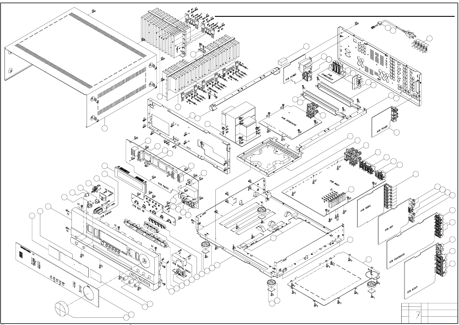
EXPLODED VIEW
NAME
PARTS
NO.
DWG.
NO.
74
Page 17
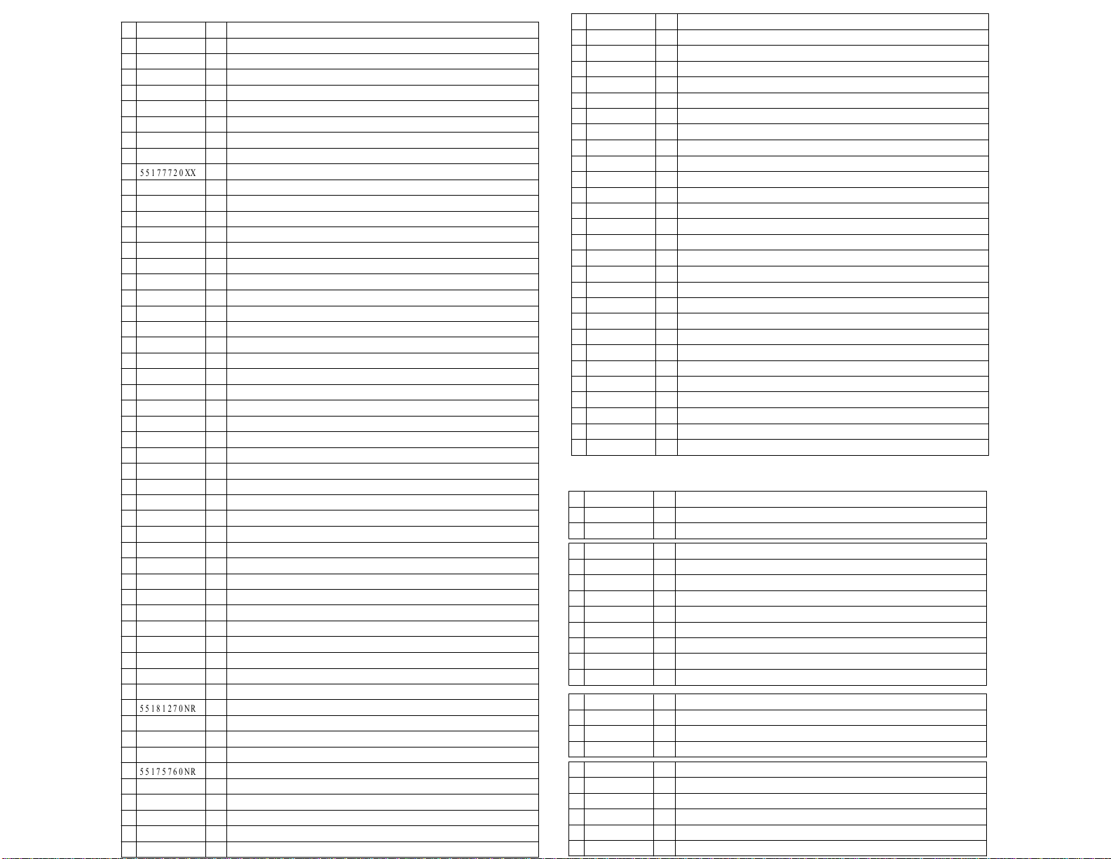
17
J85000017200
55181270
55175760XX
AVR 5 2 0 EXPLODED VIEW P ART LIST
To c o m #
NO.
1
55178050XX
2
55182450NR
3
55088400XX
4
55124350XX
5
55178000NR
6
55178020XX
7
55177810XX
8
55177820XX
9
55177720XX
10
55177800XX
11
55191560XX
12
55177740XX
13
55177910XX
14
55177990XX
15
55177750XX
16
55178030XX
17
55177790XX
18
55125440XX
19
55175240XX
20
55182550XX
21
55177760XX
22
55177780XX
23
55174760XX
24
55178110XX
25
5517807BXX
26
55113740XX
27
55179910OO
55113960XX
28
29
55179920OO
30
55177570XX
55134900NR
31
32
55178940XX
33
55178440XX
34
55155930XX
35
55177960XX
36
55178930XX
37
55255710XX
38
55191790XX
BLANK
39
40
55191780XX
41
55178250XX
42
55178170XX
43
55181270NR
44
55125180XX
55178310XX
45
46
55178400XX
47
55175760NR
55206550NR
48
55176360XX
49
55176420XX
50
51
55176390XX
55178230XX
52
Q'TY
AC P U N C O VE R TO P
1
D IS P LAY VF D H N A- 1 6 L L1 8
1
CONN- PHJAC 6.35 ST HORZ EST- J6313 BK 0 0
1
1
AC PUN BRACKET HEADP HONE
1
SW PUSH POWER SWITCH 5.0A 250.0V 100MI0OHM 1T 2P
AC MLD BUTTON INDICATOR STAND- BY
1
AC DEC BUTTON P OWER
1
AC DEC BUTTON S TANDBY
1
AC DEC CABINET P ANEL FRONT 5 1 0
1
AC D E C C R YS TAL F ILT E R DIS P L AY
1
1
AC NON- METAL DIFFUSER 0.2T 62.5*41 WH
AC DEC KN O B MAIN HIP S 9 4 H
1
AC D E C C R YS TAL D IS P LAY AVR 5 2 01
1
AC NON- METAL DIFFUSER 0.2T 59.6*41 WH
3
AC DEC KN O B TONE
2
AC MLD BUTTON INDICATOR VIDEO 4
1
AC DEC BUTTON 7 KEY
3
D- LE M TOTX1 7 8 B RD R ND C L
1
CON P H ONO S CKT RC A 1 P W/ GN D J E 0 1 00 0 3 MG
AC PUN SH IELD DIGITAL ET
1
AC DEC BUTTON 3 KEY
1
AC DEC BUTTON 5 KEY1
AC FOOT RUBBER ROUND 3.0MM 25 .0MM JIS 60 Y DIA
4
AC F O O T AS S Y R O U N D 1 2 . 5 MM 5 0 MM
4
1
AC CPL CABINET CHASS IS MAIN SECC 1 .0 T
CON P HONO S CKT RCA- 3 0 7 3 P INS
1
2
PR- ROT 100K0 OHM NON- LINEAR RK14K12400BQ 0 0
CON DIN SCKT SOCKET CONNECTOR SVHS EST- S 4 0 8 J
1
1
PR- ROT 100K0 OHM NON- LINEAR RK14K12400BR 0 0
AC PUN SH IELD FENCE TONE
11
11 SWIROT EC16B24204A5 5V 500U0A 10T 3P 0 0
AC P LAS TI C MO L D R E F R AC T O R E WH
2
11
AC MLD HOLDE R FL- GUIDE
1
IC- REMOTE RPM6938- RSIP- A3 RECEIVER 38KHZ
AC P L AS TIC MO L D R E F R AC TO R C WH
1
AC P LAS TI C MO L D R E F R AC T O R F WH
1
AC PUN BRACKET HEATSINK SECC1 .2 T
AC ME TAL HE ATS IN K( S U R R )
1
AC ME TAL HE ATS IN K( MAIN )
1
1
AC CPL CABINET CHASS IS FRONT SECC 1 .0 T
2
AC P UN B R AC K E T F R AME - GU IDE S E C C T1 . 0
1
TF - LAM P OWE R - TR AN S FO R M E R 1 2 0 V
1
AC ML D C L AMP AC C O R D
1
WIRE- MCRDM 0.8 2 MM2 1 8 3 0 MM BK CORD POWER UL S P T2
1
AC BUFFER CUS HION (A) EVA
1
TF- LAM 110V STANDBY 120V
1
CONN- SPE AC OUTLET 2P 110V FE 12.75MM 2 BK 0 0
1
CON PHONO SCKT RCA 9P W/ GNDCAP JK090122LN
4
AC PUN BRACKET BKT GROUND ET 0.5 T
CON PHONO SCKT STEREO J ACK JW3 5 0 S
3
AC P U N B R AC K E T P C B 2
SNam e
BLANK
53
55177890XX
54
55
55178300XX
55191390XX
56
57
5517809BXX
58
55262430XX
59
55177300XX
60
BLANK
61
55191400XX
62
55191420XX
55191480XX
63
55191370XX64
55176330XX
65
66
55149520XX
67
55191600XX
68
55125440NR
69
55175950XX
70
55176350XX
71
55176330XX
72
55207740XX
73
55191410XX
55191800XX
74
55178080XX
75
55125220XX
76
77
55176400XX
78
55182890NR
79
BLANK
80 BLANK
XXXX
55178960XX
XX
55148840NR
XX
55127070XX
S1
55127120XX
S2
55309240XX
S3
55127090XX
S4
55127280XX
S5
55164800XX
S6
55178320XX
S7
55135460XX
S9
55309350XX
N1
W1
55127300XX
W2
55127310XX
W3
55168690XX
W4
55131730XX
20932870XX
55149150XX
55174780XX
552178430XX
55178380XX
55178620XX
AC C P L R E AR P AN E L AVR 5 2 0
1
AC BUFFER CUS HION- BRK'T EVA
3
CONN- SPE TERMINAL SPKR 4P SH0410376P
1
1
AC P UN C O VE R TR AN S B O TTO M T1 . 0
AC P UN B R AC K E T P R O TE C T
1
AC MSA ASY KST- M1 1 1 4 MW1 - 6 0 TU MODULE
1
CONN- S P E TERMINAL SP KR 6P
1
1
CON PHONO SCKT RCA 4P JW- 4104RSA
CON PHONO SCKT RCA 6P JW- 4105RSB
1
CON PHONO SCKT RCA 1P JACK JE010003XN
1
CON PHONO SCKT RCA 4P JW4104RS GND
1
CON DIN SCKT MIX SOCKET RCA- 1 1 8 J P 1 S
7
CON P H ONO S CKT RC A 2 P W/ GN DC AP J W- 1 5 0 2 S N OO
1
D- LEM TOTX17 8B RD RND CL
1
CON P H ONO S CKT RC A 1 P W/ GN D J E 0 1 00 0 3 MN
1
CON PHONO SCKT RCA 6P JW- 4105RSS W/ GNDCAP
1
CON PHONO SCKT RCA 4P JW4104RS GND
1
CON PHONO SCKT RCA 2P JE021163TN BRN/ TAN
1
1
CON PHONO SCKT RCA 4P JW- 4104RSB
CON P HONO S CKT RCA 6 P J W41 0 5 RS G W/ GNDCAP
1
AC P UN COVER BOTTOM SECC T1 .0
1
AC BUFFER P CB
11
AC METAL HEATSINK REG 118*20*50H
1
CONN- SPE JUMPER PLUG 2PIN
5
AC SPRING PLATE SPRING GND C5212 0.2T
11
FCORE FERRIT MAGNET RING34 34.5X21X12 K- 150
1
64
SCREW- ST 3MM 10MM
SCREW- ST 3MM 8MM
34
SCREW- SPEC 4MM 10MM
4
8
SCREW- ST 4MM 8MM
10
SCREW- ST 3MM 6MM
1
S CR EW 3 MM 8 MM
25
SCREW- ST 3MM 12MM
59
SCREW- SPEC 3MM 10MM
4
N UT- HE XAGO N 4 . 0 MM 5 . 0 MM CIR C ULAR E XTER N AL 5 3
15
WAS H E R - S P R IN G 3
10
WAS H E R - F L AT 3
4
WAS H E R - S P R IN G 4
4
WAS H E R - F L AT 4
2
AC PRI LABEL QC CHECK CRKD1 2 1 7 ( 2 0 X13 MM)
2
AC P RI LABE L RIS K
AC P RI LABE L DATE
1
2
AC P R I L AB E L S E R IAL AVR 5 2 0
2
AC PR I LABEL BARCODE AVR5 2 0
1
AC P RI LABE L " P LEAS E RE MOVE.. ."
Page 18
Thu Mar 21 17:29:13 2002
18
Page 19

19
AVR520
harman/kardon
harman/kardon
Service bulletin # H/K2003-07 Sept. 2003
To: All harman/kardon Service Centers
Model: AVR110/210/310/510, AVR120/220; AVR320/520
Subject: Various Complaints
For Complaints:
NO AUDIO
NOISE
INTERMITTENT NOISE
INTERMITENT AUDIO
Possible Solution:
Voltages may be too high on DSP Buffer IC or DSP IC
All modifications are done to the DSP board.
AVR110/210/310/510
AVR120/220
Remove BD5 and replace with two 1N4148 diodes in series.
Remove R43 and R90 (3.3Ω) and replace each with a 1N4148 diode.
(See diagram Page 2 for location and polarity)
AVR320/520
Remove BD25 and replace with two 1N4148 diodes in series.
(See diagram Page 2 for location and polarity)
In all cases the 1N4148 diode(s) you need to add should be normal 2-lead axial components, like h/k
part# 13-0482 or equivalent (not SMD devices).
Warranty labor rate: MINOR repair
Service Bulletin
Page 20

20
AVR520
MODELS: AVR110/210/310/510
AVR120/220
harman/kardon
MODELS: AVR320/520
Page 21

AVR520
harman/kardon
harman/kardon
TECH TIPS
Troubleshooting tips and solutions to common service problems
For models: AVR110/120/210/220/310/320/510/520/7000 TIP# HKTT2003-01
Subject: Backup Memory on AVR series receivers
In the event of a complaint of “the receiver is losing its memory (any programmed system settings)
when the unit is turned o ff, or after th e unit is unplugged (briefly*)”:
Check and replace:
C216 (all models above except AVR7000)
C730 (AVR7000 only)
Location: On the front PCB, 0.047 Farad 5.5v capacitor, h/k part# 55134360.
* After appr oximately t wo weeks of bei ng disconnected f r om AC supply, even a normally functioning recei ver will lose
any programmed settings and switch t o default settings.
21
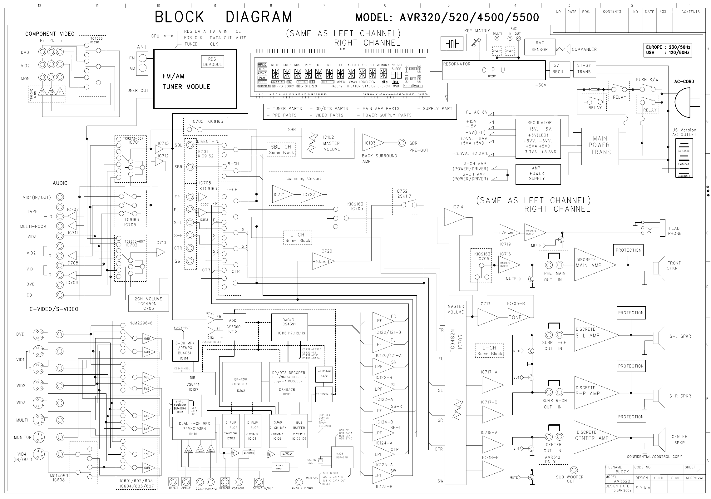
Page 22
22
AVR520
Idle Adustment Procedure
1. MAIN B'D
Turn POWER ON and wait 10 minutes, set controls VR401,VR402,VR501
in order to make voltages on both ends of WA401,WA402,WA403
20mV. See locations below
harman/kardon
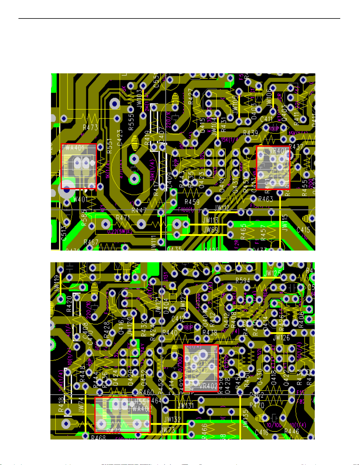
Page 23
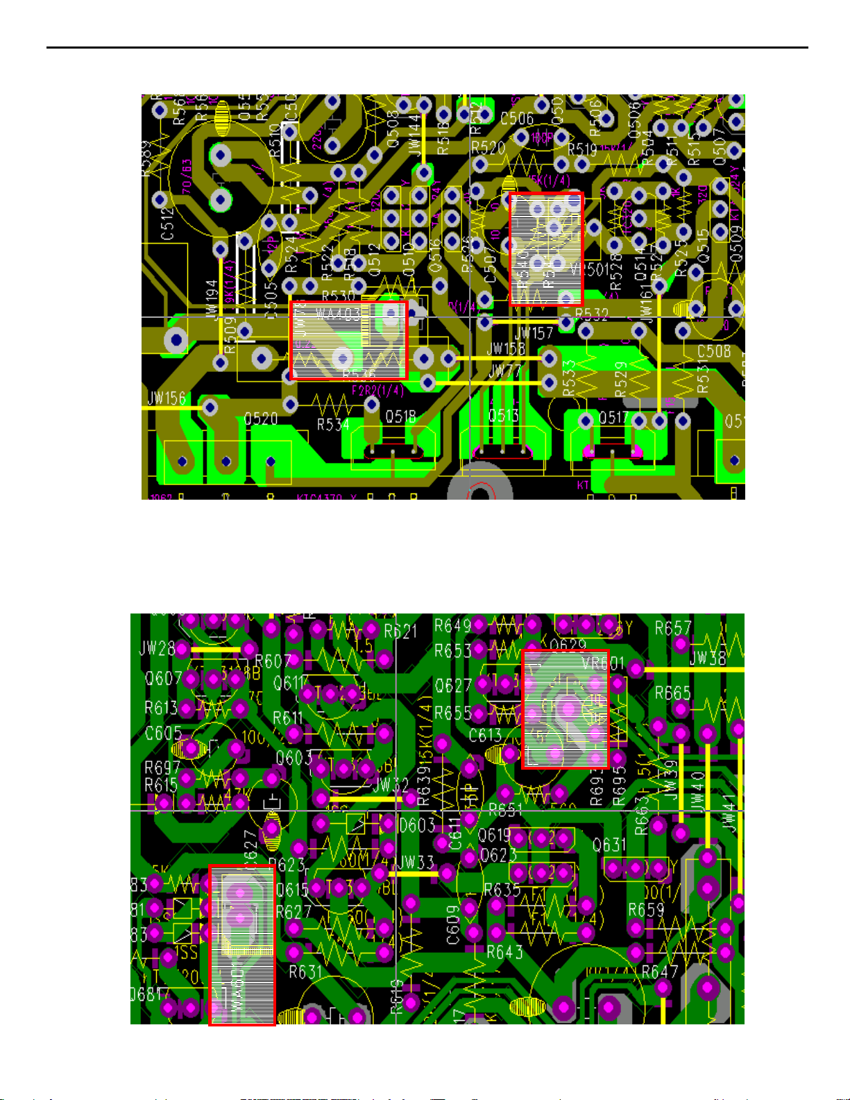
23
AVR520
harman/kardon
2. SURROUND B'D
Turn POWER ON and wait 10 minutes, set controls VR601,VR602
in order to make voltages on both ends of WA601,WA602
20mV. See locations below
Page 24
24
AVR520
harman/kardon
Page 25

25
AVR520
AVR520 Electrical Parts List
Main PCB
harman/kardon
Ref.
Designator
Part Number Qty Description
Capacitors
C101 20267830 1 PC CE 47U0F +20% 16.0V 85C
C102 20267830 1 PC CE 47U0F +20% 16.0V 85C
C103 15002130 1 PC CE 10U0F +20% 16.0V 85C
C104 15002130 1 PC CE 10U0F +20% 16.0V 85C
C105 20936650 1 PC CC 100P0F +10% -10% 50.0V Y5P
C106 20936650 1 PC CC 100P0F +10% -10% 50.0V Y5P
C107 20936650 1 PC CC 100P0F +10% -10% 50.0V Y5P
C108 20936650 1 PC CC 100P0F +10% -10% 50.0V Y5P
C109 20293470 1 PC CC 100N0F +80% -20% 50.0V F
C110 20936650 1 PC CC 100P0F +10% -10% 50.0V Y5P
C111 20936650 1 PC CC 100P0F +10% -10% 50.0V Y5P
C112 20936650 1 PC CC 100P0F +10% -10% 50.0V Y5P
C113 20936650 1 PC CC 100P0F +10% -10% 50.0V Y5P
C114 20250040 1 PC CC 220P0F +10% -10% 50.0V Y5P
C115 20250040 1 PC CC 220P0F +10% -10% 50.0V Y5P
C116 20250040 1 PC CC 220P0F +10% -10% 50.0V Y5P
C117 20250040 1 PC CC 220P0F +10% -10% 50.0V Y5P
C118 20293470 1 PC CC 100N0F +80% -20% 50.0V F
C119 20936650 1 PC CC 100P0F +10% -10% 50.0V Y5P
C120 20936650 1 PC CC 100P0F +10% -10% 50.0V Y5P
C121 20936650 1 PC CC 100P0F +10% -10% 50.0V Y5P
C122 20936650 1 PC CC 100P0F +10% -10% 50.0V Y5P
C123 20293470 1 PC CC 100N0F +80% -20% 50.0V F
C124 20293470 1 PC CC 100N0F +80% -20% 50.0V F
C125 20936650 1 PC CC 100P0F +10% -10% 50.0V Y5P
C126 20936650 1 PC CC 100P0F +10% -10% 50.0V Y5P
C127 20293470 1 PC CC 100N0F +80% -20% 50.0V F
C128 20936650 1 PC CC 100P0F +10% -10% 50.0V Y5P
C129 20936650 1 PC CC 100P0F +10% -10% 50.0V Y5P
C130 20936650 1 PC CC 100P0F +10% -10% 50.0V Y5P
C131 20293470 1 PC CC 100N0F +80% -20% 50.0V F
C401 20268880 1 PC CE 10U0F +20% 50.0V 85C
C402 20268880 1 PC CE 10U0F +20% 50.0V 85C
C403 11055300 1 PC CC 68P0F +5% -5% 50.0V NP0
C404 11055300 1 PC CC 68P0F +5% -5% 50.0V NP0
C405 20269070 1 PC CE 100U0F +20% 25.0V 85C
C406 20269070 1 PC CE 100U0F +20% 25.0V 85C
C407 20269080 1 PC CE 220U0F +20% 10.0V 85C
C408 20269080 1 PC CE 220U0F +20% 10.0V 85C
C409 30936070 1 PC CC 12P0F +5% -5% 50.0V NP0
C410 30936070 1 PC CC 12P0F +5% -5% 50.0V NP0
C411 60439150 1 PC CC 33P0F +5% -5% 50.0V NP0
C412 60439150 1 PC CC 33P0F +5% -5% 50.0V NP0
C413 20268880 1 PC CE 10U0F +20% 50.0V 85C
C414 20268880 1 PC CE 10U0F +20% 50.0V 85C
C415 20268880 1 PC CE 10U0F +20% 50.0V 85C
C416 20268880 1 PC CE 10U0F +20% 50.0V 85C
C417 55179360 1 PC CPM 100N0F +10% 63.0V
Page 26

26
AVR520
harman/kardon
Ref.
Designator
C418 55179360 1 PC CPM 100N0F +10% 63.0V
C419 55179360 1 PC CPM 100N0F +10% 63.0V
C420 55179360 1 PC CPM 100N0F +10% 63.0V
C425 11055540 1 PC CC 2N2F +10% -10% 50.0V Y5P
C426 11055540 1 PC CC 2N2F +10% -10% 50.0V Y5P
C431 10364820 1 PC CPF 47N0F +10% 100.0V
C432 10364820 1 PC CPF 47N0F +10% 100.0V
C433 10364820 1 PC CPF 47N0F +10% 100.0V
C483 55095430 1 PC CPM 100N0F +10% 250.0V
C484 10364820 1 PC CPF 47N0F +10% 100.0V
C489 20268880 1 PC CE 10U0F +20% 50.0V 85C
C490 20268880 1 PC CE 10U0F +20% 50.0V 85C
C492 20268880 1 PC CE 10U0F +20% 50.0V 85C
C494 20268880 1 PC CE 10U0F +20% 50.0V 85C
C496 20268880 1 PC CE 10U0F +20% 50.0V 85C
C497 20268880 1 PC CE 10U0F +20% 50.0V 85C
C498 20268880 1 PC CE 10U0F +20% 50.0V 85C
C501 20268880 1 PC CE 10U0F +20% 50.0V 85C
C502 11055300 1 PC CC 68P0F +5% -5% 50.0V NP0
C503 20269070 1 PC CE 100U0F +20% 25.0V 85C
C504 20269080 1 PC CE 220U0F +20% 10.0V 85C
C505 30936070 1 PC CC 12P0F +5% -5% 50.0V NP0
C506 60439150 1 PC CC 33P0F +5% -5% 50.0V NP0
C507 20268880 1 PC CE 10U0F +20% 50.0V 85C
C508 20268880 1 PC CE 10U0F +20% 50.0V 85C
C509 55179360 1 PC CPM 100N0F +10% 63.0V
C510 55179360 1 PC CPM 100N0F +10% 63.0V
C513 11055540 1 PC CC 2N2F +10% -10% 50.0V Y5P
C551 55179400 1 PC CPM 68N0F +5% 63.0V
C552 55179400 1 PC CPM 68N0F +5% 63.0V
C553 55179400 1 PC CPM 68N0F +5% 63.0V
C554 20252670 1 PC CE 470U0F +20% 10.0V 85C
C555 70428520 1 PC CC 10N0F +10% -10% 50.0V Y5P
C556 70428520 1 PC CC 10N0F +10% -10% 50.0V Y5P
C564 55095430 1 PC CPM 100N0F +10% 250.0V
C565 55095430 1 PC CPM 100N0F +10% 250.0V
C566 10364820 1 PC CPF 47N0F +10% 100.0V
C567 10364820 1 PC CPF 47N0F +10% 100.0V
C568 15002130 1 PC CE 10U0F +20% 16.0V 85C
C569 40433580 1 PC CC 680P0F +10% -10% 50.0V Y5P
C570 40433580 1 PC CC 680P0F +10% -10% 50.0V Y5P
C571 40433580 1 PC CC 680P0F +10% -10% 50.0V Y5P
C421 13076940 1 PC CE 470U0F +20% 63.0V 85C
C422 13076940 1 PC CE 470U0F +20% 63.0V 85C
C423 13076940 1 PC CE 470U0F +20% 63.0V 85C
C424 13076940 1 PC CE 470U0F +20% 63.0V 85C
C481 55180370 1 PC CE 10MI0F +20% 63.0V 85C
C482 55180370 1 PC CE 10MI0F +20% 63.0V 85C
C485 40433130 1 PC CE 2MI2F +20% 35.0V 85C
C486 40433130 1 PC CE 2MI2F +20% 35.0V 85C
C487 55126160 1 PC CE 6MI8F +20% 16.0V 85C
C488 13039870 1 PC CE 2MI2F +20% 16.0V 85C
C511 13076940 1 PC CE 470U0F +20% 63.0V 85C
C512 13076940 1 PC CE 470U0F +20% 63.0V 85C
Part Number Qty Description
Page 27

27
AVR520
harman/kardon
Ref.
Designator
Part Number Qty Description
Semiconductors
D401 70436540 1 PC D-SLP 1N4148 100.0V 150E-3A
D402 70436540 1 PC D-SLP 1N4148 100.0V 150E-3A
D403 70436540 1 PC D-SLP 1N4148 100.0V 150E-3A
D404 70436540 1 PC D-SLP 1N4148 100.0V 150E-3A
D405 70436540 1 PC D-SLP 1N4148 100.0V 150E-3A
D406 70436540 1 PC D-SLP 1N4148 100.0V 150E-3A
D501 70436540 1 PC D-SLP 1N4148 100.0V 150E-3A
D502 70436540 1 PC D-SLP 1N4148 100.0V 150E-3A
D551 70436540 1 PC D-SLP 1N4148 100.0V 150E-3A
D552 70436540 1 PC D-SLP 1N4148 100.0V 150E-3A
D553 70436540 1 PC D-SLP 1N4148 100.0V 150E-3A
D554 70436540 1 PC D-SLP 1N4148 100.0V 150E-3A
D555 70436540 1 PC D-SLP 1N4148 100.0V 150E-3A
D556 70436540 1 PC D-SLP 1N4148 100.0V 150E-3A
D567 70436540 1 PC D-SLP 1N4148 100.0V 150E-3A
Q401 20556600 1 PC TR-SHPLF KTC3200BL N 100MI0A 120V
Q402 20556600 1 PC TR-SHPLF KTC3200BL N 100MI0A 120V
Q403 20556600 1 PC TR-SHPLF KTC3200BL N 100MI0A 120V
Q404 20556600 1 PC TR-SHPLF KTC3200BL N 100MI0A 120V
Q405 20556600 1 PC TR-SHPLF KTC3200BL N 100MI0A 120V
Q406 20556600 1 PC TR-SHPLF KTC3200BL N 100MI0A 120V
Q407 20508080 1 PC TR-SLPLF KTC3198BL N 150MI0A
Q408 20508080 1 PC TR-SLPLF KTC3198BL N 150MI0A
Q411 20647850 1 PC TR-SHPLF KTA1268BL P 100MI0A 120V
Q412 20647850 1 PC TR-SHPLF KTA1268BL P 100MI0A 120V
Q413 20647850 1 PC TR-SHPLF KTA1268BL P 100MI0A 120V
Q414 20647850 1 PC TR-SHPLF KTA1268BL P 100MI0A 120V
Q415 20556600 1 PC TR-SHPLF KTC3200BL N 100MI0A 120V
Q416 20556600 1 PC TR-SHPLF KTC3200BL N 100MI0A 120V
Q417 55133260 1 PC TR-SLPLF KTA1024 Y P 50MI0A -150V
Q418 55133260 1 PC TR-SLPLF KTA1024 Y P 50MI0A -150V
Q419 55133240 1 PC TR-SLPLF KTC3206 Y N 50MI0A 150V
Q420 55133240 1 PC TR-SLPLF KTC3206 Y N 50MI0A 150V
Q421 55133260 1 PC TR-SLPLF KTA1024 Y P 50MI0A -150V
Q422 55133260 1 PC TR-SLPLF KTA1024 Y P 50MI0A -150V
Q423 55133240 1 PC TR-SLPLF KTC3206 Y N 50MI0A 150V
Q424 55133240 1 PC TR-SLPLF KTC3206 Y N 50MI0A 150V
Q427 20556600 1 PC TR-SHPLF KTC3200BL N 100MI0A 120V
Q428 20556600 1 PC TR-SHPLF KTC3200BL N 100MI0A 120V
Q429 55133240 1 PC TR-SLPLF KTC3206 Y N 50MI0A 150V
Q430 55133240 1 PC TR-SLPLF KTC3206 Y N 50MI0A 150V
Q431 55133260 1 PC TR-SLPLF KTA1024 Y P 50MI0A -150V
Q432 55133260 1 PC TR-SLPLF KTA1024 Y P 50MI0A -150V
Q501 20556600 1 PC TR-SHPLF KTC3200BL N 100MI0A 120V
Q502 20556600 1 PC TR-SHPLF KTC3200BL N 100MI0A 120V
Q503 20556600 1 PC TR-SHPLF KTC3200BL N 100MI0A 120V
Q504 20508080 1 PC TR-SLPLF KTC3198BL N 150MI0A
Q506 20647850 1 PC TR-SHPLF KTA1268BL P 100MI0A 120V
Q507 20647850 1 PC TR-SHPLF KTA1268BL P 100MI0A 120V
Q508 20556600 1 PC TR-SHPLF KTC3200BL N 100MI0A 120V
Q509 55133260 1 PC TR-SLPLF KTA1024 Y P 50MI0A -150V
Page 28

s
28
AVR520
harman/kardon
Ref.
Designator
Q510 55133240 1 PC TR-SLPLF KTC3206 Y N 50MI0A 150V
Q511 55133260 1 PC TR-SLPLF KTA1024 Y P 50MI0A -150V
Q512 55133240 1 PC TR-SLPLF KTC3206 Y N 50MI0A 150V
Q514 20556600 1 PC TR-SHPLF KTC3200BL N 100MI0A 120V
Q515 55133240 1 PC TR-SLPLF KTC3206 Y N 50MI0A 150V
Q516 55133260 1 PC TR-SLPLF KTA1024 Y P 50MI0A -150V
Q551 20556600 1 PC TR-SHPLF KTC3200BL N 100MI0A 120V
Q552 20556600 1 PC TR-SHPLF KTC3200BL N 100MI0A 120V
Q553 20556600 1 PC TR-SHPLF KTC3200BL N 100MI0A 120V
Q554 20508080 1 PC TR-SLPLF KTC3198BL N 150MI0A
Q555 20508080 1 PC TR-SLPLF KTC3198BL N 150MI0A
Q556 20508080 1 PC TR-SLPLF KTC3198BL N 150MI0A
Q557 20508210 1 PC TR-SLPLF KTA1266 Y P 150MI0A
Q558 55133260 1 PC TR-SLPLF KTA1024 Y P 50MI0A -150V
Q559 55179230 1 PC TR-SLPSWA KRC107M N
Q561 20647850 1 PC TR-SHPLF KTA1268BL P 100MI0A 120V
IC101 55142240 1 PC IC-OPERAMP NJM2068DD DUAL OP
IC481 20832440 1 PC IC-REGPOSFXD KIA7815API NORMAL
IC482 55124020 1 PC IC-REGNEGFXD KIA7915PI NORMAL
IC483 55125450 1 PC IC-REGPOSFXD BA033T NORMAL
IC484 55123960 1 PC IC-REGPOSFXD KIA7805API NORMAL
IC485 55123960 1 PC IC-REGPOSFXD KIA7805API NORMAL
IC486 55123990 1 PC IC-REGNEGFXD KIA7905PI NORMAL
IC487 55179240 1 PC IC-REGULADJ KA337 TO-220
D481 55179320 1 PC D-BRDLC BRIDGE BU10-04
D482 55179300 1 PC D-BRDLC BRIDGE W2-04F FRONTIER
D568 55125540 1 PC D-BRDLC BU6-04F
Q425 55179200 1 PC TR-SHPLF 2SC4883A N 2.0A
Q426 55179200 1 PC TR-SHPLF 2SC4883A N 2.0A
Q433 55179190 1 PC TR-SHPLF 2SA1859A P -2.0A
Q434 55179190 1 PC TR-SHPLF 2SA1859A P -2.0A
Q435 55179200 1 PC TR-SHPLF 2SC4883A N 2.0A
Q436 55179200 1 PC TR-SHPLF 2SC4883A N 2.0A
Q437 55179180 1 PC TR-SHPLF 2SC5358-R N 15.0A
Q438 55179180 1 PC TR-SHPLF 2SC5358-R N 15.0A
Q439 55179150 1 PC TR-SHPLF 2SA1986-R P -15.0A
Q440 55179150 1 PC TR-SHPLF 2SA1986-R P -15.0A
Q513 55179200 1 PC TR-SHPLF 2SC4883A N 2.0A
Q517 55179190 1 PC TR-SHPLF 2SA1859A P -2.0A
Q518 55179200 1 PC TR-SHPLF 2SC4883A N 2.0A
Q519 55179180 1 PC TR-SHPLF 2SC5358-R N 15.0A
Q520 55179150 1 PC TR-SHPLF 2SA1986-R P -15.0A
Part Number Qty Description
Resistor
R101 30939510 1 PC RCF 100K0 OHM +5% 250MI0W
R102 30939510 1 PC RCF 100K0 OHM +5% 250MI0W
R103 90571120 1 PC RCF 12K0 OHM +5% 250MI0W
R104 90571120 1 PC RCF 12K0 OHM +5% 250MI0W
R105 11059640 1 PC RCF 1K0 OHM +5% 250MI0W
R106 11059640 1 PC RCF 1K0 OHM +5% 250MI0W
R107 50882950 1 PC RCF 100R0 OHM +5% 250MI0W
R108 30939510 1 PC RCF 100K0 OHM +5% 250MI0W
R109 30939510 1 PC RCF 100K0 OHM +5% 250MI0W
Page 29

29
AVR520
harman/kardon
Ref.
Designator
R110 50882950 1 PC RCF 100R0 OHM +5% 250MI0W
R111 50882970 1 PC RCF 470R0 OHM +5% 250MI0W
R112 20469460 1 PC RCF 2K2 OHM +5% 250MI0W
R113 30939510 1 PC RCF 100K0 OHM +5% 250MI0W
R114 30939510 1 PC RCF 100K0 OHM +5% 250MI0W
R115 50882970 1 PC RCF 470R0 OHM +5% 250MI0W
R116 50882970 1 PC RCF 470R0 OHM +5% 250MI0W
R117 30939510 1 PC RCF 100K0 OHM +5% 250MI0W
R118 30939510 1 PC RCF 100K0 OHM +5% 250MI0W
R119 50882970 1 PC RCF 470R0 OHM +5% 250MI0W
R120 50882970 1 PC RCF 470R0 OHM +5% 250MI0W
R121 50882970 1 PC RCF 470R0 OHM +5% 250MI0W
R122 50882970 1 PC RCF 470R0 OHM +5% 250MI0W
R123 50882970 1 PC RCF 470R0 OHM +5% 250MI0W
R125 50882970 1 PC RCF 470R0 OHM +5% 250MI0W
R126 50882970 1 PC RCF 470R0 OHM +5% 250MI0W
R127 30939510 1 PC RCF 100K0 OHM +5% 250MI0W
R128 30939510 1 PC RCF 100K0 OHM +5% 250MI0W
R129 30939510 1 PC RCF 100K0 OHM +5% 250MI0W
R130 50882970 1 PC RCF 470R0 OHM +5% 250MI0W
R132 30939510 1 PC RCF 100K0 OHM +5% 250MI0W
R401 60441550 1 PC RCF 330R0 OHM +5% 250MI0W
R402 60441550 1 PC RCF 330R0 OHM +5% 250MI0W
R403 90571130 1 PC RCF 39K0 OHM +5% 250MI0W
R404 90571130 1 PC RCF 39K0 OHM +5% 250MI0W
R405 40435630 1 PC RCF 1K5 OHM +5% 250MI0W
R406 40435630 1 PC RCF 1K5 OHM +5% 250MI0W
R407 40435630 1 PC RCF 1K5 OHM +5% 250MI0W
R408 40435630 1 PC RCF 1K5 OHM +5% 250MI0W
R409 20469450 1 PC RCF 220R0 OHM +5% 250MI0W
R410 20469450 1 PC RCF 220R0 OHM +5% 250MI0W
R411 20469450 1 PC RCF 220R0 OHM +5% 250MI0W
R412 20469450 1 PC RCF 220R0 OHM +5% 250MI0W
R413 11059610 1 PC RCF 270R0 OHM +5% 250MI0W
R414 11059610 1 PC RCF 270R0 OHM +5% 250MI0W
R415 20469510 1 PC RCF 43K0 OHM +5% 250MI0W
R416 20469510 1 PC RCF 43K0 OHM +5% 250MI0W
R417 90571130 1 PC RCF 39K0 OHM +5% 250MI0W
R418 90571130 1 PC RCF 39K0 OHM +5% 250MI0W
R419 11059660 1 PC RCF 2K0 OHM +5% 250MI0W
R420 11059660 1 PC RCF 2K0 OHM +5% 250MI0W
R421 60441560 1 PC RCF 560R0 OHM +5% 250MI0W
R422 60441560 1 PC RCF 560R0 OHM +5% 250MI0W
R423 60441560 1 PC RCF 560R0 OHM +5% 250MI0W
R424 60441560 1 PC RCF 560R0 OHM +5% 250MI0W
R425 60441560 1 PC RCF 560R0 OHM +5% 250MI0W
R426 60441560 1 PC RCF 560R0 OHM +5% 250MI0W
R427 60441560 1 PC RCF 560R0 OHM +5% 250MI0W
R428 60441560 1 PC RCF 560R0 OHM +5% 250MI0W
R429 60441560 1 PC RCF 560R0 OHM +5% 250MI0W
R430 60441560 1 PC RCF 560R0 OHM +5% 250MI0W
R431 60441560 1 PC RCF 560R0 OHM +5% 250MI0W
R432 60441560 1 PC RCF 560R0 OHM +5% 250MI0W
R433 50882960 1 PC RCF 150R0 OHM +5% 250MI0W
Part Number Qty Description
Page 30

30
AVR520
harman/kardon
Ref.
Designator
R434 50882960 1 PC RCF 150R0 OHM +5% 250MI0W
R435 50882960 1 PC RCF 150R0 OHM +5% 250MI0W
R436 50882960 1 PC RCF 150R0 OHM +5% 250MI0W
R437 50883010 1 PC RCF 15K0 OHM +5% 250MI0W
R438 50883010 1 PC RCF 15K0 OHM +5% 250MI0W
R439 50883010 1 PC RCF 15K0 OHM +5% 250MI0W
R440 50883010 1 PC RCF 15K0 OHM +5% 250MI0W
R441 50882960 1 PC RCF 150R0 OHM +5% 250MI0W
R442 50882960 1 PC RCF 150R0 OHM +5% 250MI0W
R443 50882960 1 PC RCF 150R0 OHM +5% 250MI0W
R444 50882960 1 PC RCF 150R0 OHM +5% 250MI0W
R445 55232810 1 PC RMF 10R0 OHM +5% 500MI0W
R446 55232810 1 PC RMF 10R0 OHM +5% 500MI0W
R447 55232810 1 PC RMF 10R0 OHM +5% 500MI0W
R448 55232810 1 PC RMF 10R0 OHM +5% 500MI0W
R449 11059640 1 PC RCF 1K0 OHM +5% 250MI0W
R450 11059640 1 PC RCF 1K0 OHM +5% 250MI0W
R451 60441560 1 PC RCF 560R0 OHM +5% 250MI0W
R452 60441560 1 PC RCF 560R0 OHM +5% 250MI0W
R453 40435640 1 PC RCF 4K7 OHM +5% 250MI0W
R454 40435640 1 PC RCF 4K7 OHM +5% 250MI0W
R455 70430560 1 PC RCF 5K6 OHM +5% 250MI0W
R456 70430560 1 PC RCF 5K6 OHM +5% 250MI0W
R457 50882950 1 PC RCF 100R0 OHM +5% 250MI0W
R458 50882950 1 PC RCF 100R0 OHM +5% 250MI0W
R459 50882950 1 PC RCF 100R0 OHM +5% 250MI0W
R460 50882950 1 PC RCF 100R0 OHM +5% 250MI0W
R461 30939370 1 PC RCF 15R0 OHM +5% 250MI0W
R462 30939370 1 PC RCF 15R0 OHM +5% 250MI0W
R463 30939370 1 PC RCF 15R0 OHM +5% 250MI0W
R464 30939370 1 PC RCF 15R0 OHM +5% 250MI0W
R465 40438910 1 PC RCF 2R2 OHM +5% 250MI0W
R466 40438910 1 PC RCF 2R2 OHM +5% 250MI0W
R467 40438910 1 PC RCF 2R2 OHM +5% 250MI0W
R468 40438910 1 PC RCF 2R2 OHM +5% 250MI0W
R469 11059590 1 PC RCF 82R0 OHM +5% 250MI0W
R470 11059590 1 PC RCF 82R0 OHM +5% 250MI0W
R473 55242290 1 PC RCF 10R0 OHM +5% 250MI0W
R474 55242290 1 PC RCF 10R0 OHM +5% 250MI0W
R477 30939360 1 PC RCF 10R0 OHM +5% 250MI0W
R478 30939360 1 PC RCF 10R0 OHM +5% 250MI0W
R489 20469450 1 PC RCF 220R0 OHM +5% 250MI0W
R490 11059630 1 PC RCF 680R0 OHM +5% 250MI0W
R501 60441550 1 PC RCF 330R0 OHM +5% 250MI0W
R502 90571130 1 PC RCF 39K0 OHM +5% 250MI0W
R503 40435630 1 PC RCF 1K5 OHM +5% 250MI0W
R504 40435630 1 PC RCF 1K5 OHM +5% 250MI0W
R505 20469450 1 PC RCF 220R0 OHM +5% 250MI0W
R506 20469450 1 PC RCF 220R0 OHM +5% 250MI0W
R507 11059610 1 PC RCF 270R0 OHM +5% 250MI0W
R508 20469510 1 PC RCF 43K0 OHM +5% 250MI0W
R509 90571130 1 PC RCF 39K0 OHM +5% 250MI0W
R510 11059660 1 PC RCF 2K0 OHM +5% 250MI0W
R511 60441560 1 PC RCF 560R0 OHM +5% 250MI0W
Part Number Qty Description
Page 31

31
AVR520
harman/kardon
Ref.
Designator
R512 60441560 1 PC RCF 560R0 OHM +5% 250MI0W
R513 60441560 1 PC RCF 560R0 OHM +5% 250MI0W
R514 60441560 1 PC RCF 560R0 OHM +5% 250MI0W
R515 60441560 1 PC RCF 560R0 OHM +5% 250MI0W
R516 60441560 1 PC RCF 560R0 OHM +5% 250MI0W
R517 50882960 1 PC RCF 150R0 OHM +5% 250MI0W
R518 50882960 1 PC RCF 150R0 OHM +5% 250MI0W
R519 50883010 1 PC RCF 15K0 OHM +5% 250MI0W
R520 50883010 1 PC RCF 15K0 OHM +5% 250MI0W
R521 50882960 1 PC RCF 150R0 OHM +5% 250MI0W
R522 50882960 1 PC RCF 150R0 OHM +5% 250MI0W
R523 55232810 1 PC RMF 10R0 OHM +5% 500MI0W
R524 55232810 1 PC RMF 10R0 OHM +5% 500MI0W
R525 11059640 1 PC RCF 1K0 OHM +5% 250MI0W
R526 60441560 1 PC RCF 560R0 OHM +5% 250MI0W
R527 40435640 1 PC RCF 4K7 OHM +5% 250MI0W
R528 70430560 1 PC RCF 5K6 OHM +5% 250MI0W
R529 50882950 1 PC RCF 100R0 OHM +5% 250MI0W
R530 50882950 1 PC RCF 100R0 OHM +5% 250MI0W
R531 30939370 1 PC RCF 15R0 OHM +5% 250MI0W
R532 30939370 1 PC RCF 15R0 OHM +5% 250MI0W
R533 40438910 1 PC RCF 2R2 OHM +5% 250MI0W
R534 40438910 1 PC RCF 2R2 OHM +5% 250MI0W
R535 11059590 1 PC RCF 82R0 OHM +5% 250MI0W
R537 55242290 1 PC RCF 10R0 OHM +5% 250MI0W
R539 55242290 1 PC RCF 10R0 OHM +5% 250MI0W
R551 40435630 1 PC RCF 1K5 OHM +5% 250MI0W
R552 40435630 1 PC RCF 1K5 OHM +5% 250MI0W
R553 50883010 1 PC RCF 15K0 OHM +5% 250MI0W
R554 50883010 1 PC RCF 15K0 OHM +5% 250MI0W
R555 60441580 1 PC RCF 22K0 OHM +5% 250MI0W
R556 60441580 1 PC RCF 22K0 OHM +5% 250MI0W
R557 40435630 1 PC RCF 1K5 OHM +5% 250MI0W
R558 50883010 1 PC RCF 15K0 OHM +5% 250MI0W
R559 60441580 1 PC RCF 22K0 OHM +5% 250MI0W
R561 70430570 1 PC RCF 8K2 OHM +5% 250MI0W
R562 11059710 1 PC RCF 56K0 OHM +5% 250MI0W
R563 11059710 1 PC RCF 56K0 OHM +5% 250MI0W
R564 11059710 1 PC RCF 56K0 OHM +5% 250MI0W
R565 50883010 1 PC RCF 15K0 OHM +5% 250MI0W
R566 50882950 1 PC RCF 100R0 OHM +5% 250MI0W
R567 30939480 1 PC RCF 10K0 OHM +5% 250MI0W
R568 30939480 1 PC RCF 10K0 OHM +5% 250MI0W
R569 30939480 1 PC RCF 10K0 OHM +5% 250MI0W
R570 11059610 1 PC RCF 270R0 OHM +5% 250MI0W
R571 80437030 1 PC RCF 27K0 OHM +5% 250MI0W
R585 40435630 1 PC RCF 1K5 OHM +5% 250MI0W
R586 40435630 1 PC RCF 1K5 OHM +5% 250MI0W
R587 90571130 1 PC RCF 39K0 OHM +5% 250MI0W
R588 90571130 1 PC RCF 39K0 OHM +5% 250MI0W
R589 40435630 1 PC RCF 1K5 OHM +5% 250MI0W
R590 90571130 1 PC RCF 39K0 OHM +5% 250MI0W
R591 30939480 1 PC RCF 10K0 OHM +5% 250MI0W
R592 90571130 1 PC RCF 39K0 OHM +5% 250MI0W
Part Number Qty Description
Page 32

32
AVR520
harman/kardon
Ref.
Designator
R593 50882970 1 PC RCF 470R0 OHM +5% 250MI0W
R594 50882970 1 PC RCF 470R0 OHM +5% 250MI0W
R595 50882970 1 PC RCF 470R0 OHM +5% 250MI0W
R471 55179340 1 PC RW 220MI0 OHM +5% 5.0W 100PPM/'C -100PPM/'C
R472 55179340 1 PC RW 220MI0 OHM +5% 5.0W 100PPM/'C -100PPM/'C
R475 60442550 1 PC RMOF 10R0 OHM +5% 1.0W
R476 60442550 1 PC RMOF 10R0 OHM +5% 1.0W
R481 15022710 1 PC RMOF 10R0 OHM +5% 2.0W
R482 15022710 1 PC RMOF 10R0 OHM +5% 2.0W
R483 15022710 1 PC RMOF 10R0 OHM +5% 2.0W
R484 80442780 1 PC RMOF 4R7 OHM +5% 2.0W
R485 80442780 1 PC RMOF 4R7 OHM +5% 2.0W
R486 80442780 1 PC RMOF 4R7 OHM +5% 2.0W
R487 40440550 1 PC RMOF 3R3 OHM +5% 2.0W
R536 55179340 1 PC RW 220MI0 OHM +5% 5.0W 100PPM/'C -100PPM/'C
R538 60442550 1 PC RMOF 10R0 OHM +5% 1.0W
VR401 55152180 1 PC PR 1K0 OHM +30% 100MI0W
VR402 55152180 1 PC PR 1K0 OHM +30% 100MI0W
VR501 55152180 1 PC PR 1K0 OHM +30% 100MI0W
Part Number Qty Description
Miscellaneous
CN401 55171550 1 PC CON 3.96MM PITCH MOLEX 35313-0310
CN402 55146610 1 PC CONN 2.5MM 6 MA ST NAT 0 0
CN403 55146570 1 PC CONN 2.5MM 3 MA ST NAT 0 0
CN407 55171520 1 PC CONN 2.0MM 5 MA ST NAT MOLEX 35336-0510 0 0
CN408 55125010 1 PC CONN 2.0MM 15 MA ST NAT MOLEX 35336-1510 0 0
CN409 55125010 1 PC CONN 2.0MM 15 MA ST NAT MOLEX 35336-1510 0 0
CN410 55125010 1 PC CONN 2.0MM 15 MA ST NAT MOLEX 35336-1510 0 0
CN411 55125010 1 PC CONN 2.0MM 15 MA ST NAT MOLEX 35336-1510 0 0
CN412 55174630 1 PC CONN 2.0MM 19 MA ST NAT MOLEX 35336-1910 0 0
CN413 55174620 1 PC CONN 2.0MM 17 MA ST NAT MOLEX 35336-1710 0 0
CN414 55179440 1 PC CONN 1.25MM 27 FE ST WH GF120-27S-TS 2794 A4
CN415 55205630 1 PC CONN 2.0MM 16 MA ST NAT MOLEX 35336-1610 0 0
CN416 55123330 1 PC CONN 2.0MM 6 MA ST NAT LW2002P06 0 0
CN417 55146570 1 PC CONN 2.5MM 3 MA ST NAT 0 0
CN418 55124960 1 PC CONN 2.0MM 11 MA ST NAT MOLEX 35336-1110 0 0
CN419 55174590 1 PC CONN 2.0MM 9 MA ST NAT MOLEX 35336-0910 0 0
CP401 55182570 1 PC WIRECONASY UNIQUE 7P 240MM UL1533 SHIELD 28 1
50 55176400 1 PC AC HEATSINK REG 118*20*50H AVR520 -- ME
FU481 20828790 1 PC FUSULSLWBL 2.0 A 250.0 V
FU482 20828790 1 PC FUSULSLWBL 2.0 A 250.0 V
FU483 20828790 1 PC FUSULSLWBL 2.0 A 250.0 V
FU484 20828790 1 PC FUSULSLWBL 2.0 A 250.0 V
G011 55135980 1 PC TERMLUG GND
JK404 55191420 1 PC CON PHONO SCKT RCA 4P JW-4104RSA
JK405 55191480 1 PC CON PHONO SCKT RCA 6P JW-4105RSB
JK407 55176330 1 PC CON PHONO SCKT RCA 4P JW4104RS GND
JK408 55191370 1 PC CON PHONO SCKT RCA 1P JACK JE010003XN
JK503 55191400 1 PC CONN-SPE TERMINAL SPKR 6P SH0611705P FE 19MM 6 BK 0 0
L401 55179560 1 PC LFA 1MM 10MM 5 LEFT
L402 55179560 1 PC LFA 1MM 10MM 5 LEFT
L501 55179560 1 PC LFA 1MM 10MM 5 LEFT
P551 55179640 1 PC POS 100R0 OHM 16.0V
Page 33

33
AVR520
harman/kardon
Ref.
Designator
FH401 55170330 1 PC TERMFUSEHLDR FUSE-HOLDER J4210020001X
FH402 55170330 1 PC TERMFUSEHLDR FUSE-HOLDER J4210020001X
FH403 55170330 1 PC TERMFUSEHLDR FUSE-HOLDER J4210020001X
FH404 55170330 1 PC TERMFUSEHLDR FUSE-HOLDER J4210020001X
FH405 55170330 1 PC TERMFUSEHLDR FUSE-HOLDER J4210020001X
FH406 55170330 1 PC TERMFUSEHLDR FUSE-HOLDER J4210020001X
FH407 55170330 1 PC TERMFUSEHLDR FUSE-HOLDER J4210020001X
FH408 55170330 1 PC TERMFUSEHLDR FUSE-HOLDER J4210020001X
W101 20720260 1 PC WCL 100-05-05 UL1007 HOOK-UP 26 100MM BK 5 5 20182780 0.0MM
W401 55244370 1 PC WIRECONASY UNIQUE 1P 250MM UL1007 PVC DISCRETE 18 1
W402 20899230 1 PC WCL 050-05-05 UL1007 HOOK-UP 26 50MM BK 5 5 20182780 0.0MM
WA401 55146560 1 PC CONN 2.5MM 2 MA ST NAT 0 0
WA402 55146560 1 PC CONN 2.5MM 2 MA ST NAT 0 0
WA403 55146560 1 PC CONN 2.5MM 2 MA ST NAT 0 0
Part Number Qty Description
20 20430330 2 PC AC RAW TERMINAL 29614B 8.5MM
Input PCB
Capacitors
C101 20268880 1 PC CE 10U0F +20% 50.0V 85C
C102 20268880 1 PC CE 10U0F +20% 50.0V 85C
C103 20268880 1 PC CE 10U0F +20% 50.0V 85C
C104 20268880 1 PC CE 10U0F +20% 50.0V 85C
C105 20267830 1 PC CE 47U0F +20% 16.0V 85C
C106 20267830 1 PC CE 47U0F +20% 16.0V 85C
C106 20268880 1 PC CE 10U0F +20% 50.0V 85C
C107 20268880 1 PC CE 10U0F +20% 50.0V 85C
C108 20268880 1 PC CE 10U0F +20% 50.0V 85C
C109 20936650 1 PC CC 100P0F +10% -10% 50.0V Y5P
C110 20936650 1 PC CC 100P0F +10% -10% 50.0V Y5P
C111 20936650 1 PC CC 100P0F +10% -10% 50.0V Y5P
C112 20268880 1 PC CE 10U0F +20% 50.0V 85C
C113 20268880 1 PC CE 10U0F +20% 50.0V 85C
C114 20936650 1 PC CC 100P0F +10% -10% 50.0V Y5P
C115 20936650 1 PC CC 100P0F +10% -10% 50.0V Y5P
C116 20936650 1 PC CC 100P0F +10% -10% 50.0V Y5P
C117 20250040 1 PC CC 220P0F +10% -10% 50.0V Y5P
C118 20250040 1 PC CC 220P0F +10% -10% 50.0V Y5P
C119 20246470 1 PC CC 100N0F +80% -20% 25.0V Z5V
C120 20250040 1 PC CC 220P0F +10% -10% 50.0V Y5P
C121 20250040 1 PC CC 220P0F +10% -10% 50.0V Y5P
C122 20250040 1 PC CC 220P0F +10% -10% 50.0V Y5P
C123 20246470 1 PC CC 100N0F +80% -20% 25.0V Z5V
C124 20250040 1 PC CC 220P0F +10% -10% 50.0V Y5P
C125 20250040 1 PC CC 220P0F +10% -10% 50.0V Y5P
C126 20246470 1 PC CC 100N0F +80% -20% 25.0V Z5V
C127 20267830 1 PC CE 47U0F +20% 16.0V 85C
C128 20267830 1 PC CE 47U0F +20% 16.0V 85C
C129 10291350 1 PC CC 33P0F +5% -5% 50.0V SL
C130 20268880 1 PC CE 10U0F +20% 50.0V 85C
C131 10291350 1 PC CC 33P0F +5% -5% 50.0V SL
C132 20268880 1 PC CE 10U0F +20% 50.0V 85C
C133 20267830 1 PC CE 47U0F +20% 16.0V 85C
C134 20267830 1 PC CE 47U0F +20% 16.0V 85C
C135 20268880 1 PC CE 10U0F +20% 50.0V 85C
Page 34

s
34
AVR520
harman/kardon
Ref.
Designator
C136 20268880 1 PC CE 10U0F +20% 50.0V 85C
C137 20267830 1 PC CE 47U0F +20% 16.0V 85C
C138 20267830 1 PC CE 47U0F +20% 16.0V 85C
Part Number Qty Description
Semiconductors
IC101 55142710 1 PC IC-SWITCH KIC9162AF ANALOG SWITCH
IC102 55142720 1 PC IC-LOWFREQ KIC9459F SOP24 TONE/VOL/BAL/MUTE
IC103 55142610 1 PC IC-OPERAMP NJM2068M DUAL OP
IC104 55142610 1 PC IC-OPERAMP NJM2068M DUAL OP
Q101 55133220 1 PC TR-SLPLF DTA114YSA P 100MI0A
Q102 55133290 1 PC TR-SLPLF KTD1302 B N 300MI0A 20V
Q103 55133290 1 PC TR-SLPLF KTD1302 B N 300MI0A 20V
Q104 55133210 1 PC TR-SLPLF DTC114YSA N 100MI0A
Resistor
R143 80440510 1 PC RMGCFMIN 0 OHM +0% 100MI0W
R144 80440510 1 PC RMGCFMIN 0 OHM +0% 100MI0W
R145 80440510 1 PC RMGCFMIN 0 OHM +0% 100MI0W
R146 80440510 1 PC RMGCFMIN 0 OHM +0% 100MI0W
R147 80440510 1 PC RMGCFMIN 0 OHM +0% 100MI0W
R148 80440510 1 PC RMGCFMIN 0 OHM +0% 100MI0W
R149 80440510 1 PC RMGCFMIN 0 OHM +0% 100MI0W
R150 80440510 1 PC RMGCFMIN 0 OHM +0% 100MI0W
R151 80440510 1 PC RMGCFMIN 0 OHM +0% 100MI0W
R152 80440510 1 PC RMGCFMIN 0 OHM +0% 100MI0W
R101 50882950 1 PC RCF 100R0 OHM +5% 250MI0W
R102 50882950 1 PC RCF 100R0 OHM +5% 250MI0W
R103 30939510 1 PC RCF 100K0 OHM +5% 250MI0W
R104 30939510 1 PC RCF 100K0 OHM +5% 250MI0W
R105 30939510 1 PC RCF 100K0 OHM +5% 250MI0W
R106 30939510 1 PC RCF 100K0 OHM +5% 250MI0W
R107 11059640 1 PC RCF 1K0 OHM +5% 250MI0W
R108 11059640 1 PC RCF 1K0 OHM +5% 250MI0W
R109 11059640 1 PC RCF 1K0 OHM +5% 250MI0W
R110 30939510 1 PC RCF 100K0 OHM +5% 250MI0W
R111 30939510 1 PC RCF 100K0 OHM +5% 250MI0W
R112 11059640 1 PC RCF 1K0 OHM +5% 250MI0W
R113 11059640 1 PC RCF 1K0 OHM +5% 250MI0W
R114 30939510 1 PC RCF 100K0 OHM +5% 250MI0W
R115 30939510 1 PC RCF 100K0 OHM +5% 250MI0W
R116 11059640 1 PC RCF 1K0 OHM +5% 250MI0W
R117 11059640 1 PC RCF 1K0 OHM +5% 250MI0W
R118 11059640 1 PC RCF 1K0 OHM +5% 250MI0W
R119 11059640 1 PC RCF 1K0 OHM +5% 250MI0W
R120 11059640 1 PC RCF 1K0 OHM +5% 250MI0W
R121 50882950 1 PC RCF 100R0 OHM +5% 250MI0W
R122 50882950 1 PC RCF 100R0 OHM +5% 250MI0W
R123 30939480 1 PC RCF 10K0 OHM +5% 250MI0W
R124 11059640 1 PC RCF 1K0 OHM +5% 250MI0W
R125 70430560 1 PC RCF 5K6 OHM +5% 250MI0W
R126 11059640 1 PC RCF 1K0 OHM +5% 250MI0W
R127 30939510 1 PC RCF 100K0 OHM +5% 250MI0W
R128 50882970 1 PC RCF 470R0 OHM +5% 250MI0W
R129 70430560 1 PC RCF 5K6 OHM +5% 250MI0W
R130 11059640 1 PC RCF 1K0 OHM +5% 250MI0W
Page 35

35
AVR520
harman/kardon
Ref.
Designator
R131 30939510 1 PC RCF 100K0 OHM +5% 250MI0W
R132 50882970 1 PC RCF 470R0 OHM +5% 250MI0W
R133 50882950 1 PC RCF 100R0 OHM +5% 250MI0W
R134 50882950 1 PC RCF 100R0 OHM +5% 250MI0W
R135 30939510 1 PC RCF 100K0 OHM +5% 250MI0W
R136 30939510 1 PC RCF 100K0 OHM +5% 250MI0W
R137 50882950 1 PC RCF 100R0 OHM +5% 250MI0W
R138 50882950 1 PC RCF 100R0 OHM +5% 250MI0W
R139 50882950 1 PC RCF 100R0 OHM +5% 250MI0W
R140 50882950 1 PC RCF 100R0 OHM +5% 250MI0W
R141 11059780 1 PC RCF 1M0 OHM +5% 250MI0W
R142 60441600 1 PC RCF 68K0 OHM +5% 250MI0W
Part Number Qty Description
Miscellaneous
CN101 55125030 1 PC CONN 2.0MM 11 MA R NAT MOLEX 35237-1110 0 0
CN102 55175920 1 PC WIRECONASY UNIQUE 10P 520MM UL1533 SHIELD 28 1
CN103 55175910 1 PC WIRECONASY UNIQUE 12P 390MM UL1533 SHIELD 26 1
CN201 55174640 1 PC CONN 2.0MM 9 MA R NAT SOCKET MOLEX 35237-0910 0 0
CP101 55174640 1 PC CONN 2.0MM 9 MA R NAT SOCKET MOLEX 35237-0910 0 0
CP102 55125030 1 PC CONN 2.0MM 11 MA R NAT MOLEX 35237-1110 0 0
CP104 55175910 1 PC WIRECONASY UNIQUE 12P 390MM UL1533 SHIELD 26 1
CP105 55175920 1 PC WIRECONASY UNIQUE 10P 520MM UL1533 SHIELD 28 1
JK101 55207740 1 PC CON PHONO SCKT RCA 2P JE021163TN BRN/TAN
JK102 55176350 1 PC CON PHONO SCKT RCA 6P JW-4105RSS W/GNDCAP
JK102 55191410 1 PC CON PHONO SCKT RCA 4P JW-4104RSB
JK103 55176330 1 PC CON PHONO SCKT RCA 4P JW4104RS GND
JK103 55191800 1 PC CON PHONO SCKT RCA 6P JW4105RSG W/GNDCAP WH,RD,BU,WH,RD,BU
Surround PCB
Capacitors
C350 20252050 1 PC CE 100U0F +20% 6.3V 85C
C351 20252050 1 PC CE 100U0F +20% 6.3V 85C
C352 20268880 1 PC CE 10U0F +20% 50.0V 85C
C353 20268880 1 PC CE 10U0F +20% 50.0V 85C
C354 20268880 1 PC CE 10U0F +20% 50.0V 85C
C355 20268840 1 PC CE 1U0F +20% 50.0V 85C
C356 20268840 1 PC CE 1U0F +20% 50.0V 85C
C357 20268840 1 PC CE 1U0F +20% 50.0V 85C
C358 20268840 1 PC CE 1U0F +20% 50.0V 85C
C359 20268840 1 PC CE 1U0F +20% 50.0V 85C
C360 20268840 1 PC CE 1U0F +20% 50.0V 85C
C361 20252050 1 PC CE 100U0F +20% 6.3V 85C
C362 20246470 1 PC CC 100N0F +80% -20% 25.0V Z5V
C363 20246470 1 PC CC 100N0F +80% -20% 25.0V Z5V
C364 20246470 1 PC CC 100N0F +80% -20% 25.0V Z5V
C365 20936650 1 PC CC 100P0F +10% -10% 50.0V Y5P
C366 20246470 1 PC CC 100N0F +80% -20% 25.0V Z5V
C367 20246470 1 PC CC 100N0F +80% -20% 25.0V Z5V
C368 20246470 1 PC CC 100N0F +80% -20% 25.0V Z5V
C369 20246470 1 PC CC 100N0F +80% -20% 25.0V Z5V
C370 20936650 1 PC CC 100P0F +10% -10% 50.0V Y5P
C371 20936650 1 PC CC 100P0F +10% -10% 50.0V Y5P
C372 20267830 1 PC CE 47U0F +20% 16.0V 85C
C373 20267830 1 PC CE 47U0F +20% 16.0V 85C
Page 36

36
AVR520
harman/kardon
Ref.
Designator
C374 20267830 1 PC CE 47U0F +20% 16.0V 85C
C375 20267830 1 PC CE 47U0F +20% 16.0V 85C
C386 20246470 1 PC CC 100N0F +80% -20% 25.0V Z5V
C601 20268880 1 PC CE 10U0F +20% 50.0V 85C
C602 20268880 1 PC CE 10U0F +20% 50.0V 85C
C603 11055300 1 PC CC 68P0F +5% -5% 50.0V NP0
C604 11055300 1 PC CC 68P0F +5% -5% 50.0V NP0
C605 20269070 1 PC CE 100U0F +20% 25.0V 85C
C606 20269070 1 PC CE 100U0F +20% 25.0V 85C
C607 20269080 1 PC CE 220U0F +20% 10.0V 85C
C608 20269080 1 PC CE 220U0F +20% 10.0V 85C
C609 30936070 1 PC CC 12P0F +5% -5% 50.0V NP0
C610 30936070 1 PC CC 12P0F +5% -5% 50.0V NP0
C611 60439150 1 PC CC 33P0F +5% -5% 50.0V NP0
C612 60439150 1 PC CC 33P0F +5% -5% 50.0V NP0
C613 20268880 1 PC CE 10U0F +20% 50.0V 85C
C614 20268880 1 PC CE 10U0F +20% 50.0V 85C
C615 20268880 1 PC CE 10U0F +20% 50.0V 85C
C616 20268880 1 PC CE 10U0F +20% 50.0V 85C
C617 55179360 1 PC CPM 100N0F +10% 63.0V
C618 55179360 1 PC CPM 100N0F +10% 63.0V
C619 55179360 1 PC CPM 100N0F +10% 63.0V
C620 55179360 1 PC CPM 100N0F +10% 63.0V
C625 11055560 1 PC CC 3N3F +10% -10% 50.0V Y5P
C626 11055560 1 PC CC 3N3F +10% -10% 50.0V Y5P
C629 40433580 1 PC CC 680P0F +10% -10% 50.0V Y5P
C630 40433580 1 PC CC 680P0F +10% -10% 50.0V Y5P
C681 55179400 1 PC CPM 68N0F +5% 63.0V
C682 55179400 1 PC CPM 68N0F +5% 63.0V
C693 55095430 1 PC CPM 100N0F +10% 250.0V
C694 55095430 1 PC CPM 100N0F +10% 250.0V
C695 55095430 1 PC CPM 100N0F +10% 250.0V
C696 15002130 1 PC CE 10U0F +20% 16.0V 85C
C971 20268840 1 PC CE 1U0F +20% 50.0V 85C
C983 70428520 1 PC CC 10N0F +10% -10% 50.0V Y5P
C985 20495030 1 PC CC 100N0F +10% -10% 25.0V Y5P
C986 20268840 1 PC CE 1U0F +20% 50.0V 85C
C987 20268880 1 PC CE 10U0F +20% 50.0V 85C
C988 20495030 1 PC CC 100N0F +10% -10% 25.0V Y5P
C991 20269010 1 PC CE 47U0F +20% 50.0V 85C
C992 13039350 1 PC CE 100U0F +20% 35.0V 85C
C993 20495030 1 PC CC 100N0F +10% -10% 25.0V Y5P
C994 20495030 1 PC CC 100N0F +10% -10% 25.0V Y5P
C995 20495030 1 PC CC 100N0F +10% -10% 25.0V Y5P
C997 70428520 1 PC CC 10N0F +10% -10% 50.0V Y5P
C998 70428520 1 PC CC 10N0F +10% -10% 50.0V Y5P
C999 70428520 1 PC CC 10N0F +10% -10% 50.0V Y5P
C621 13076940 1 PC CE 470U0F +20% 63.0V 85C
C622 13076940 1 PC CE 470U0F +20% 63.0V 85C
C623 13076940 1 PC CE 470U0F +20% 63.0V 85C
C624 13076940 1 PC CE 470U0F +20% 63.0V 85C
C691 55326560 1 PC CE 6MI8F +20% 63.0V 85C
C692 55326560 1 PC CE 6MI8F +20% 63.0V 85C
C982 55095470 1 PC CC 4N7F +20% -20% 250.0V Y5V
C984 13073530 1 PC CE 470U0F +20% 50.0V 85C
C989 13073530 1 PC CE 470U0F +20% 50.0V 85C
C990 13073530 1 PC CE 470U0F +20% 50.0V 85C
Part Number Qty Description
Page 37

37
AVR520
harman/kardon
Ref.
Designator
CA81 55095460 1 PC CPPMX 100N0F +20% -20%
Part Number Qty Description
Semiconductors
D601 70436540 1 PC D-SLP 1N4148 100.0V 150E-3A
D602 70436540 1 PC D-SLP 1N4148 100.0V 150E-3A
D603 70436540 1 PC D-SLP 1N4148 100.0V 150E-3A
D604 70436540 1 PC D-SLP 1N4148 100.0V 150E-3A
D681 70436540 1 PC D-SLP 1N4148 100.0V 150E-3A
D682 70436540 1 PC D-SLP 1N4148 100.0V 150E-3A
D683 70436540 1 PC D-SLP 1N4148 100.0V 150E-3A
D684 70436540 1 PC D-SLP 1N4148 100.0V 150E-3A
D685 70436540 1 PC D-SLP 1N4148 100.0V 150E-3A
D987 70436540 1 PC D-SLP 1N4148 100.0V 150E-3A
D988 70436540 1 PC D-SLP 1N4148 100.0V 150E-3A
D991 20475340 1 PC D-ZENER BZX55B30 30V 500MI0W
D992 70436540 1 PC D-SLP 1N4148 100.0V 150E-3A
D994 20873880 1 PC D-ZENER 1N5236B 7.5V 500MI0W
D996 20526960 1 PC D-ZENER 1N5231B 5.1V 500MI0W
Q301 55133210 1 PC TR-SLPLF DTC114YSA N 100MI0A
Q601 20556600 1 PC TR-SHPLF KTC3200BL N 100MI0A 120V
Q602 20556600 1 PC TR-SHPLF KTC3200BL N 100MI0A 120V
Q603 20556600 1 PC TR-SHPLF KTC3200BL N 100MI0A 120V
Q604 20556600 1 PC TR-SHPLF KTC3200BL N 100MI0A 120V
Q605 20556600 1 PC TR-SHPLF KTC3200BL N 100MI0A 120V
Q606 20556600 1 PC TR-SHPLF KTC3200BL N 100MI0A 120V
Q607 20508080 1 PC TR-SLPLF KTC3198BL N 150MI0A
Q608 20508080 1 PC TR-SLPLF KTC3198BL N 150MI0A
Q611 20647850 1 PC TR-SHPLF KTA1268BL P 100MI0A 120V
Q612 20647850 1 PC TR-SHPLF KTA1268BL P 100MI0A 120V
Q613 20647850 1 PC TR-SHPLF KTA1268BL P 100MI0A 120V
Q614 20647850 1 PC TR-SHPLF KTA1268BL P 100MI0A 120V
Q615 20556600 1 PC TR-SHPLF KTC3200BL N 100MI0A 120V
Q616 20556600 1 PC TR-SHPLF KTC3200BL N 100MI0A 120V
Q617 55133260 1 PC TR-SLPLF KTA1024 Y P 50MI0A -150V
Q618 55133260 1 PC TR-SLPLF KTA1024 Y P 50MI0A -150V
Q619 55133240 1 PC TR-SLPLF KTC3206 Y N 50MI0A 150V
Q620 55133240 1 PC TR-SLPLF KTC3206 Y N 50MI0A 150V
Q621 55133260 1 PC TR-SLPLF KTA1024 Y P 50MI0A -150V
Q622 55133260 1 PC TR-SLPLF KTA1024 Y P 50MI0A -150V
Q623 55133240 1 PC TR-SLPLF KTC3206 Y N 50MI0A 150V
Q624 55133240 1 PC TR-SLPLF KTC3206 Y N 50MI0A 150V
Q627 20556600 1 PC TR-SHPLF KTC3200BL N 100MI0A 120V
Q628 20556600 1 PC TR-SHPLF KTC3200BL N 100MI0A 120V
Q629 55133240 1 PC TR-SLPLF KTC3206 Y N 50MI0A 150V
Q630 55133240 1 PC TR-SLPLF KTC3206 Y N 50MI0A 150V
Q631 55133260 1 PC TR-SLPLF KTA1024 Y P 50MI0A -150V
Q632 55133260 1 PC TR-SLPLF KTA1024 Y P 50MI0A -150V
Q681 20556600 1 PC TR-SHPLF KTC3200BL N 100MI0A 120V
Q682 20556600 1 PC TR-SHPLF KTC3200BL N 100MI0A 120V
Q683 20647850 1 PC TR-SHPLF KTA1268BL P 100MI0A 120V
Q981 20647850 1 PC TR-SHPLF KTA1268BL P 100MI0A 120V
Q982 55142670 1 PC TR-SLPLF MPSA06 N 500MI0A
D691 55179280 1 PC D-BRDLC BRIDGE BU8-04F FRONTIER
D981 20415060 1 PC D-SR 1N4004 400.0V 1.0A
D982 20415060 1 PC D-SR 1N4004 400.0V 1.0A
D983 20415060 1 PC D-SR 1N4004 400.0V 1.0A
Page 38

s
38
AVR520
harman/kardon
Ref.
Designator
D984 20415060 1 PC D-SR 1N4004 400.0V 1.0A
D985 20415060 1 PC D-SR 1N4004 400.0V 1.0A
D986 20415060 1 PC D-SR 1N4004 400.0V 1.0A
D989 20415060 1 PC D-SR 1N4004 400.0V 1.0A
D990 20415060 1 PC D-SR 1N4004 400.0V 1.0A
IC390 55179600 1 PC IC-LOGIC TC4053BFN SOL16 MULTIPLEXER CMOS
IC391 55175530 1 PC IC-VIDEOPROC TSH95D VIDEO AMPLIFIER
IC981 55179250 1 PC IC-REGPOSFXD KIA7805API TO-220IS NORMAL
Q625 55179200 1 PC TR-SHPLF 2SC4883A N 2.0A
Q626 55179200 1 PC TR-SHPLF 2SC4883A N 2.0A
Q633 55179190 1 PC TR-SHPLF 2SA1859A P -2.0A
Q634 55179190 1 PC TR-SHPLF 2SA1859A P -2.0A
Q635 55179200 1 PC TR-SHPLF 2SC4883A N 2.0A
Q636 55179200 1 PC TR-SHPLF 2SC4883A N 2.0A
Q637 55179180 1 PC TR-SHPLF 2SC5358-R N 15.0A
Q638 55179180 1 PC TR-SHPLF 2SC5358-R N 15.0A
Q639 55179150 1 PC TR-SHPLF 2SA1986-R P -15.0A
Q640 55179150 1 PC TR-SHPLF 2SA1986-R P -15.0A
Part Number Qty Description
Resistor
R350 70430520 1 PC RCF 75R0 OHM +5% 250MI0W
R351 70430520 1 PC RCF 75R0 OHM +5% 250MI0W
R352 60441580 1 PC RCF 22K0 OHM +5% 250MI0W
R353 70430520 1 PC RCF 75R0 OHM +5% 250MI0W
R354 70430520 1 PC RCF 75R0 OHM +5% 250MI0W
R355 30939360 1 PC RCF 10R0 OHM +5% 250MI0W
R356 70430520 1 PC RCF 75R0 OHM +5% 250MI0W
R357 70430520 1 PC RCF 75R0 OHM +5% 250MI0W
R358 30939360 1 PC RCF 10R0 OHM +5% 250MI0W
R359 70430520 1 PC RCF 75R0 OHM +5% 250MI0W
R360 30939360 1 PC RCF 10R0 OHM +5% 250MI0W
R361 60441560 1 PC RCF 560R0 OHM +5% 250MI0W
R362 80436970 1 PC RCF 510R0 OHM +5% 250MI0W
R363 30939480 1 PC RCF 10K0 OHM +5% 250MI0W
R364 60441560 1 PC RCF 560R0 OHM +5% 250MI0W
R365 80436970 1 PC RCF 510R0 OHM +5% 250MI0W
R366 30939480 1 PC RCF 10K0 OHM +5% 250MI0W
R367 60441560 1 PC RCF 560R0 OHM +5% 250MI0W
R368 80436970 1 PC RCF 510R0 OHM +5% 250MI0W
R369 30939480 1 PC RCF 10K0 OHM +5% 250MI0W
R370 70430520 1 PC RCF 75R0 OHM +5% 250MI0W
R371 60441580 1 PC RCF 22K0 OHM +5% 250MI0W
R372 70430520 1 PC RCF 75R0 OHM +5% 250MI0W
R373 60441580 1 PC RCF 22K0 OHM +5% 250MI0W
R374 30939480 1 PC RCF 10K0 OHM +5% 250MI0W
R601 60441550 1 PC RCF 330R0 OHM +5% 250MI0W
R602 60441550 1 PC RCF 330R0 OHM +5% 250MI0W
R603 90571130 1 PC RCF 39K0 OHM +5% 250MI0W
R604 90571130 1 PC RCF 39K0 OHM +5% 250MI0W
R605 40435630 1 PC RCF 1K5 OHM +5% 250MI0W
R606 40435630 1 PC RCF 1K5 OHM +5% 250MI0W
R607 40435630 1 PC RCF 1K5 OHM +5% 250MI0W
R608 40435630 1 PC RCF 1K5 OHM +5% 250MI0W
R609 20469450 1 PC RCF 220R0 OHM +5% 250MI0W
R610 20469450 1 PC RCF 220R0 OHM +5% 250MI0W
R611 20469450 1 PC RCF 220R0 OHM +5% 250MI0W
Page 39

39
AVR520
harman/kardon
Ref.
Designator
R612 20469450 1 PC RCF 220R0 OHM +5% 250MI0W
R613 11059610 1 PC RCF 270R0 OHM +5% 250MI0W
R614 11059610 1 PC RCF 270R0 OHM +5% 250MI0W
R615 20469510 1 PC RCF 43K0 OHM +5% 250MI0W
R616 20469510 1 PC RCF 43K0 OHM +5% 250MI0W
R617 90571130 1 PC RCF 39K0 OHM +5% 250MI0W
R618 90571130 1 PC RCF 39K0 OHM +5% 250MI0W
R619 11059660 1 PC RCF 2K0 OHM +5% 250MI0W
R620 11059660 1 PC RCF 2K0 OHM +5% 250MI0W
R621 60441560 1 PC RCF 560R0 OHM +5% 250MI0W
R622 60441560 1 PC RCF 560R0 OHM +5% 250MI0W
R623 60441560 1 PC RCF 560R0 OHM +5% 250MI0W
R624 60441560 1 PC RCF 560R0 OHM +5% 250MI0W
R625 60441560 1 PC RCF 560R0 OHM +5% 250MI0W
R626 60441560 1 PC RCF 560R0 OHM +5% 250MI0W
R627 60441560 1 PC RCF 560R0 OHM +5% 250MI0W
R628 60441560 1 PC RCF 560R0 OHM +5% 250MI0W
R629 60441560 1 PC RCF 560R0 OHM +5% 250MI0W
R630 60441560 1 PC RCF 560R0 OHM +5% 250MI0W
R631 60441560 1 PC RCF 560R0 OHM +5% 250MI0W
R632 60441560 1 PC RCF 560R0 OHM +5% 250MI0W
R633 50882960 1 PC RCF 150R0 OHM +5% 250MI0W
R634 50882960 1 PC RCF 150R0 OHM +5% 250MI0W
R635 50882960 1 PC RCF 150R0 OHM +5% 250MI0W
R636 50882960 1 PC RCF 150R0 OHM +5% 250MI0W
R637 50883010 1 PC RCF 15K0 OHM +5% 250MI0W
R638 50883010 1 PC RCF 15K0 OHM +5% 250MI0W
R639 50883010 1 PC RCF 15K0 OHM +5% 250MI0W
R640 50883010 1 PC RCF 15K0 OHM +5% 250MI0W
R641 50882960 1 PC RCF 150R0 OHM +5% 250MI0W
R642 50882960 1 PC RCF 150R0 OHM +5% 250MI0W
R643 50882960 1 PC RCF 150R0 OHM +5% 250MI0W
R644 50882960 1 PC RCF 150R0 OHM +5% 250MI0W
R645 55232810 1 PC RMF 10R0 OHM +5% 500MI0W
R646 55232810 1 PC RMF 10R0 OHM +5% 500MI0W
R647 55232810 1 PC RMF 10R0 OHM +5% 500MI0W
R648 55232810 1 PC RMF 10R0 OHM +5% 500MI0W
R649 11059640 1 PC RCF 1K0 OHM +5% 250MI0W
R650 11059640 1 PC RCF 1K0 OHM +5% 250MI0W
R651 60441560 1 PC RCF 560R0 OHM +5% 250MI0W
R652 60441560 1 PC RCF 560R0 OHM +5% 250MI0W
R653 40435640 1 PC RCF 4K7 OHM +5% 250MI0W
R654 40435640 1 PC RCF 4K7 OHM +5% 250MI0W
R655 70430560 1 PC RCF 5K6 OHM +5% 250MI0W
R656 70430560 1 PC RCF 5K6 OHM +5% 250MI0W
R657 50882950 1 PC RCF 100R0 OHM +5% 250MI0W
R658 50882950 1 PC RCF 100R0 OHM +5% 250MI0W
R659 50882950 1 PC RCF 100R0 OHM +5% 250MI0W
R660 50882950 1 PC RCF 100R0 OHM +5% 250MI0W
R661 30939370 1 PC RCF 15R0 OHM +5% 250MI0W
R662 30939370 1 PC RCF 15R0 OHM +5% 250MI0W
R663 30939370 1 PC RCF 15R0 OHM +5% 250MI0W
R664 30939370 1 PC RCF 15R0 OHM +5% 250MI0W
R665 40438910 1 PC RCF 2R2 OHM +5% 250MI0W
R666 40438910 1 PC RCF 2R2 OHM +5% 250MI0W
R667 40438910 1 PC RCF 2R2 OHM +5% 250MI0W
R668 40438910 1 PC RCF 2R2 OHM +5% 250MI0W
Part Number Qty Description
Page 40

40
AVR520
harman/kardon
Ref.
Designator
R669 11059590 1 PC RCF 82R0 OHM +5% 250MI0W
R670 11059590 1 PC RCF 82R0 OHM +5% 250MI0W
R673 30939360 1 PC RCF 10R0 OHM +5% 250MI0W
R674 30939360 1 PC RCF 10R0 OHM +5% 250MI0W
R677 30939360 1 PC RCF 10R0 OHM +5% 250MI0W
R678 30939360 1 PC RCF 10R0 OHM +5% 250MI0W
R679 50882970 1 PC RCF 470R0 OHM +5% 250MI0W
R680 50882970 1 PC RCF 470R0 OHM +5% 250MI0W
R681 40435630 1 PC RCF 1K5 OHM +5% 250MI0W
R682 40435630 1 PC RCF 1K5 OHM +5% 250MI0W
R683 50883010 1 PC RCF 15K0 OHM +5% 250MI0W
R684 50883010 1 PC RCF 15K0 OHM +5% 250MI0W
R685 60441580 1 PC RCF 22K0 OHM +5% 250MI0W
R686 60441580 1 PC RCF 22K0 OHM +5% 250MI0W
R687 40435630 1 PC RCF 1K5 OHM +5% 250MI0W
R688 40435630 1 PC RCF 1K5 OHM +5% 250MI0W
R689 90571130 1 PC RCF 39K0 OHM +5% 250MI0W
R690 90571130 1 PC RCF 39K0 OHM +5% 250MI0W
R691 30939480 1 PC RCF 10K0 OHM +5% 250MI0W
R692 90571130 1 PC RCF 39K0 OHM +5% 250MI0W
R971 30939480 1 PC RCF 10K0 OHM +5% 250MI0W
R972 30939510 1 PC RCF 100K0 OHM +5% 250MI0W
R981 20472530 1 PC RCF 4R7 OHM +5% 250MI0W
R982 20469460 1 PC RCF 2K2 OHM +5% 250MI0W
R983 11059640 1 PC RCF 1K0 OHM +5% 250MI0W
R984 11059670 1 PC RCF 2K7 OHM +5% 250MI0W
R985 30939380 1 PC RCF 22R0 OHM +5% 250MI0W
R986 20469460 1 PC RCF 2K2 OHM +5% 250MI0W
R987 60441560 1 PC RCF 560R0 OHM +5% 250MI0W
R988 11067570 1 PC RCF 1R0 OHM +5% 250MI0W
R989 11067570 1 PC RCF 1R0 OHM +5% 250MI0W
R993 70430560 1 PC RCF 5K6 OHM +5% 250MI0W
R671 55179340 1 PC RW 220MI0 OHM +5% 5.0W 100PPM/'C -100PPM/'C
R672 55179340 1 PC RW 220MI0 OHM +5% 5.0W 100PPM/'C -100PPM/'C
R675 60442550 1 PC RMOF 10R0 OHM +5% 1.0W
R676 60442550 1 PC RMOF 10R0 OHM +5% 1.0W
R995 55180100 1 PC RA 3M3 OHM +10% 500MI0W
VR601 55152180 1 PC PR 1K0 OHM +30% 100MI0W
VR602 55152180 1 PC PR 1K0 OHM +30% 100MI0W
Part Number Qty Description
Miscellaneous
FH981 55170330 1 PC TERMFUSEHLDR FUSE-HOLDER J4210020001X
FH982 55170330 1 PC TERMFUSEHLDR FUSE-HOLDER J4210020001X
50 55176410 1 PC AC HEATSINK 17*15*30 AVR520 -- ME
55 55127070 1 PC SCREW-ST 3MM 10MM JIS B 1122 19 0 0
AC981 55206550 1 PC CONN-SPE AC OUTLET 2P 110V FE 12.75MM 2 BK 0 0
BKT1 55176420 1 PC AC PUN BRACKET BKT GROUND ET 0.5T AVR520 -BKT2 55176420 1 PC AC PUN BRACKET BKT GROUND ET 0.5T AVR520 -C378 15041100 1 PC RA 3M3 OHM +10% 500MI0W
CN390 55123310 1 PC CONN 2.0MM 4 MA ST NAT LW2002P04 0 0
CN391 55090080 1 PC CONN 2.0MM 3 MA ST NAT LW2002P03 0 0
CN606 55191230 1 PC WIRECONASY UNIQUE 3P 864MM UL1007 PVC DISCRETE 26 1
CP390 55123310 1 PC CONN 2.0MM 4 MA ST NAT LW2002P04 0 0
CP391 55091500 1 PC RELAYPWR 12.0V 270.0OHM 10.0A 250.0V
FU981 55114060 1 PC FUSULSLWBL 7.0 A 250.0 V
H012 55180170 1 PC WIRECONASY UNIQUE 1P 200MM UL1007 PVC DISCRETE 18 1
Page 41

41
AVR520
harman/kardon
Ref.
Designator
H020 55180170 1 PC WIRECONASY UNIQUE 1P 200MM UL1007 PVC DISCRETE 18 1
JA290 55176360 1 PC CON PHONO SCKT RCA 9P W/GNDCAP JK090122LN
JK601 55191390 1 PC CONN-SPE TERMINAL SPKR 4P SH0410376P FE 19MM 4 BK 0 0
L601 55179560 1 PC LFA 1MM 10MM 5 LEFT
L602 55179560 1 PC LFA 1MM 10MM 5 LEFT
RL981 55091500 1 PC RELAYPWR 12.0V 270.0OHM 10.0A 250.0V
T981 55175760 1 PC TF-LAM 110V STANDBY 120V
WA601 55146560 1 PC CONN 2.5MM 2 MA ST NAT 0 0
WA602 55146560 1 PC CONN 2.5MM 2 MA ST NAT 0 0
WA603 55171550 1 PC CON 3.96MM PITCH MOLEX 35313-0310
WA625 55123310 1 PC CONN 2.0MM 4 MA ST NAT LW2002P04 0 0
WA981 5504884A 1 PC CON 3.96MM PITCH HEADER 2 POS
WA983 55123510 1 PC CON 3.96MM PITCH HEADER 2 POS MOLEX 35328-0210
WA985 55123510 1 PC CON 3.96MM PITCH HEADER 2 POS MOLEX 35328-0210
WA986 55146620 1 PC CONN 2.5MM 7 MA ST NAT 0 0
Part Number Qty Description
Front PCB
Capacitors
C205 20267290 1 PC CCCFMIN 100N0F +80% -20% 50.0V Y5V
C206 50882360 1 PC CCCFMIN 33P0F +5% -5% 50.0V NP0
C208 50882360 1 PC CCCFMIN 33P0F +5% -5% 50.0V NP0
C209 20267290 1 PC CCCFMIN 100N0F +80% -20% 50.0V Y5V
C211 15070900 1 PC CCCFMIN 820P0F +10% -10% 50.0V NP0
C212 15070900 1 PC CCCFMIN 820P0F +10% -10% 50.0V NP0
C213 20267290 1 PC CCCFMIN 100N0F +80% -20% 50.0V Y5V
C217 20267290 1 PC CCCFMIN 100N0F +80% -20% 50.0V Y5V
C218 20267290 1 PC CCCFMIN 100N0F +80% -20% 50.0V Y5V
C228 11058670 1 PC CCCFMIN 100P0F +5% -5% 50.0V NP0
C229 11058670 1 PC CCCFMIN 100P0F +5% -5% 50.0V NP0
C230 11058670 1 PC CCCFMIN 100P0F +5% -5% 50.0V NP0
C237 20267290 1 PC CCCFMIN 100N0F +80% -20% 50.0V Y5V
C238 20267290 1 PC CCCFMIN 100N0F +80% -20% 50.0V Y5V
C239 20267290 1 PC CCCFMIN 100N0F +80% -20% 50.0V Y5V
C240 20267290 1 PC CCCFMIN 100N0F +80% -20% 50.0V Y5V
C241 20267290 1 PC CCCFMIN 100N0F +80% -20% 50.0V Y5V
C242 20267290 1 PC CCCFMIN 100N0F +80% -20% 50.0V Y5V
C244 20267290 1 PC CCCFMIN 100N0F +80% -20% 50.0V Y5V
C245 20267290 1 PC CCCFMIN 100N0F +80% -20% 50.0V Y5V
C246 11058670 1 PC CCCFMIN 100P0F +5% -5% 50.0V NP0
C247 11058670 1 PC CCCFMIN 100P0F +5% -5% 50.0V NP0
C248 11058670 1 PC CCCFMIN 100P0F +5% -5% 50.0V NP0
CL211 11058670 1 PC CCCFMIN 100P0F +5% -5% 50.0V NP0
CR211 11058670 1 PC CCCFMIN 100P0F +5% -5% 50.0V NP0
C201 20267830 1 PC CE 47U0F +20% 16.0V 85C
C202 20267830 1 PC CE 47U0F +20% 16.0V 85C
C203 20267830 1 PC CE 47U0F +20% 16.0V 85C
C204 20269010 1 PC CE 47U0F +20% 50.0V 85C
C210 20268880 1 PC CE 10U0F +20% 50.0V 85C
C214 20267830 1 PC CE 47U0F +20% 16.0V 85C
C215 20267830 1 PC CE 47U0F +20% 16.0V 85C
C219 20269010 1 PC CE 47U0F +20% 50.0V 85C
C220 20268880 1 PC CE 10U0F +20% 50.0V 85C
C232 20267830 1 PC CE 47U0F +20% 16.0V 85C
C233 20267830 1 PC CE 47U0F +20% 16.0V 85C
C234 20268950 1 PC CE 100N0F +20% 50.0V 85C
Page 42

42
AVR520
harman/kardon
Ref.
Designator
C235 10364820 1 PC CPF 47N0F +10% 100.0V
C236 10364820 1 PC CPF 47N0F +10% 100.0V
CL201 15002130 1 PC CE 10U0F +20% 16.0V 85C
CL202 30936230 1 PC CC 100P0F +5% -5% 50.0V NP0
CL203 80434590 1 PC CC 22P0F +5% -5% 50.0V NP0
CL204 15002130 1 PC CE 10U0F +20% 16.0V 85C
CL205 15002130 1 PC CE 10U0F +20% 16.0V 85C
CL206 55179370 1 PC CPM 18N0F +5% 100.0V
CL207 55179410 1 PC CPM 82N0F +5% 100.0V
CL208 55179390 1 PC CPM 3N3F +5% 100.0V
CL209 55179370 1 PC CPM 18N0F +5% 100.0V
CR201 15002130 1 PC CE 10U0F +20% 16.0V 85C
CR202 30936230 1 PC CC 100P0F +5% -5% 50.0V NP0
CR203 80434590 1 PC CC 22P0F +5% -5% 50.0V NP0
CR204 15002130 1 PC CE 10U0F +20% 16.0V 85C
CR205 15002130 1 PC CE 10U0F +20% 16.0V 85C
CR206 55179370 1 PC CPM 18N0F +5% 100.0V
CR207 55179410 1 PC CPM 82N0F +5% 100.0V
CR208 55179390 1 PC CPM 3N3F +5% 100.0V
CR209 55179370 1 PC CPM 18N0F +5% 100.0V
C203 20267830 1 PC CE 47U0F +20% 16.0V 85C
C216 55134360 1 PC CM 47MI0F +80% -20% 5.5V 70C
Part Number Qty Description
Semiconductors
D248 20496510 1 PC D-SLP 1SS355 35.0V 225MI0A
D249 20496510 1 PC D-SLP 1SS355 35.0V 225MI0A
D250 20496510 1 PC D-SLP 1SS355 35.0V 225MI0A
D251 20496510 1 PC D-SLP 1SS355 35.0V 225MI0A
D253 20496510 1 PC D-SLP 1SS355 35.0V 225MI0A
D254 20496510 1 PC D-SLP 1SS355 35.0V 225MI0A
D255 20496510 1 PC D-SLP 1SS355 35.0V 225MI0A
D261 20496510 1 PC D-SLP 1SS355 35.0V 225MI0A
D262 20496510 1 PC D-SLP 1SS355 35.0V 225MI0A
D264 80440510 1 PC RMGCFMIN 0 OHM +0% 100MI0W
IC202 20718660 1 PC IC-LOGIC BU4094BF SHIFT REGISTER CMOS
IC203 20718660 1 PC IC-LOGIC BU4094BF SHIFT REGISTER CMOS
IC204 20718660 1 PC IC-LOGIC BU4094BF SHIFT REGISTER CMOS
Q201 55133330 1 PC TR-SSD DTC114TKA N 10K0 OHM
Q202 55133330 1 PC TR-SSD DTC114TKA N 10K0 OHM
Q203 55133330 1 PC TR-SSD DTC114TKA N 10K0 OHM
Q204 55133330 1 PC TR-SSD DTC114TKA N 10K0 OHM
Q205 55133330 1 PC TR-SSD DTC114TKA N 10K0 OHM
Q206 55133330 1 PC TR-SSD DTC114TKA N 10K0 OHM
Q207 55133330 1 PC TR-SSD DTC114TKA N 10K0 OHM
Q208 55133330 1 PC TR-SSD DTC114TKA N 10K0 OHM
Q209 55133330 1 PC TR-SSD DTC114TKA N 10K0 OHM
Q210 55133330 1 PC TR-SSD DTC114TKA N 10K0 OHM
Q211 55133330 1 PC TR-SSD DTC114TKA N 10K0 OHM
Q212 55133330 1 PC TR-SSD DTC114TKA N 10K0 OHM
Q213 55133330 1 PC TR-SSD DTC114TKA N 10K0 OHM
Q214 55133330 1 PC TR-SSD DTC114TKA N 10K0 OHM
Q215 55133330 1 PC TR-SSD DTC114TKA N 10K0 OHM
Q216 55133330 1 PC TR-SSD DTC114TKA N 10K0 OHM
Q217 55133330 1 PC TR-SSD DTC114TKA N 10K0 OHM
Q218 55133330 1 PC TR-SSD DTC114TKA N 10K0 OHM
Q219 55133330 1 PC TR-SSD DTC114TKA N 10K0 OHM
Page 43

43
AVR520
harman/kardon
Ref.
Designator
Q220 55133330 1 PC TR-SSD DTC114TKA N 10K0 OHM
Q221 55133330 1 PC TR-SSD DTC114TKA N 10K0 OHM
Q228 55133180 1 PC TR-SSD DTC114YKA N 10K0 OHM 47K0 OHM
Q229 55133180 1 PC TR-SSD DTC114YKA N 10K0 OHM 47K0 OHM
Q231 55133180 1 PC TR-SSD DTC114YKA N 10K0 OHM 47K0 OHM
Q232 55133180 1 PC TR-SSD DTC114YKA N 10K0 OHM 47K0 OHM
Q234 55133180 1 PC TR-SSD DTC114YKA N 10K0 OHM 47K0 OHM
Q236 55133190 1 PC TR-SSD DTA114YKA P 10K0 OHM 47K0 OHM
Q237 55133180 1 PC TR-SSD DTC114YKA N 10K0 OHM 47K0 OHM
Q239 55133330 1 PC TR-SSD DTC114TKA N 10K0 OHM
Q240 55133330 1 PC TR-SSD DTC114TKA N 10K0 OHM
Q243 55133190 1 PC TR-SSD DTA114YKA P 10K0 OHM 47K0 OHM
Q244 55133180 1 PC TR-SSD DTC114YKA N 10K0 OHM 47K0 OHM
Q222 55133210 1 PC TR-SLPLF DTC114YSA N 100MI0A
Q223 55133210 1 PC TR-SLPLF DTC114YSA N 100MI0A
Q224 55133210 1 PC TR-SLPLF DTC114YSA N 100MI0A
Q225 55133210 1 PC TR-SLPLF DTC114YSA N 100MI0A
Q226 55133210 1 PC TR-SLPLF DTC114YSA N 100MI0A
Q227 55142670 1 PC TR-SLPLF MPSA06 N 500MI0A
Q233 55133350 1 PC TR-SLPLF MPSA56 Y P -500MI0A -300V
Q235 55133210 1 PC TR-SLPLF DTC114YSA N 100MI0A
Q241 55133290 1 PC TR-SLPLF KTD1302 B N 300MI0A 20V
Q242 55133290 1 PC TR-SLPLF KTD1302 B N 300MI0A 20V
D201 55199400 1 PC D-LEM CT-3SGTA GN RND 3.0 CL 60M0CD
D202 55199400 1 PC D-LEM CT-3SGTA GN RND 3.0 CL 60M0CD
D203 55199400 1 PC D-LEM CT-3SGTA GN RND 3.0 CL 60M0CD
D204 55199400 1 PC D-LEM CT-3SGTA GN RND 3.0 CL 60M0CD
D205 55199400 1 PC D-LEM CT-3SGTA GN RND 3.0 CL 60M0CD
D206 55199400 1 PC D-LEM CT-3SGTA GN RND 3.0 CL 60M0CD
D207 55199400 1 PC D-LEM CT-3SGTA GN RND 3.0 CL 60M0CD
D208 55199400 1 PC D-LEM CT-3SGTA GN RND 3.0 CL 60M0CD
D209 55199400 1 PC D-LEM CT-3SGTA GN RND 3.0 CL 60M0CD
D210 55199400 1 PC D-LEM CT-3SGTA GN RND 3.0 CL 60M0CD
D211 55199400 1 PC D-LEM CT-3SGTA GN RND 3.0 CL 60M0CD
D212 55199400 1 PC D-LEM CT-3SGTA GN RND 3.0 CL 60M0CD
D213 55199400 1 PC D-LEM CT-3SGTA GN RND 3.0 CL 60M0CD
D214 55199400 1 PC D-LEM CT-3SGTA GN RND 3.0 CL 60M0CD
D215 55199400 1 PC D-LEM CT-3SGTA GN RND 3.0 CL 60M0CD
D216 55199400 1 PC D-LEM CT-3SGTA GN RND 3.0 CL 60M0CD
D217 55199400 1 PC D-LEM CT-3SGTA GN RND 3.0 CL 60M0CD
D218 55199400 1 PC D-LEM CT-3SGTA GN RND 3.0 CL 60M0CD
D219 55199400 1 PC D-LEM CT-3SGTA GN RND 3.0 CL 60M0CD
D220 55199400 1 PC D-LEM CT-3SGTA GN RND 3.0 CL 60M0CD
D221 55199400 1 PC D-LEM CT-3SGTA GN RND 3.0 CL 60M0CD
D222 55199400 1 PC D-LEM CT-3SGTA GN RND 3.0 CL 60M0CD
D223 55199400 1 PC D-LEM CT-3SGTA GN RND 3.0 CL 60M0CD
D224 55199400 1 PC D-LEM CT-3SGTA GN RND 3.0 CL 60M0CD
D225 55199400 1 PC D-LEM CT-3SGTA GN RND 3.0 CL 60M0CD
D226 55199400 1 PC D-LEM CT-3SGTA GN RND 3.0 CL 60M0CD
D227 55199400 1 PC D-LEM CT-3SGTA GN RND 3.0 CL 60M0CD
D228 55199400 1 PC D-LEM CT-3SGTA GN RND 3.0 CL 60M0CD
D229 55199400 1 PC D-LEM CT-3SGTA GN RND 3.0 CL 60M0CD
D230 55199400 1 PC D-LEM CT-3SGTA GN RND 3.0 CL 60M0CD
D231 55199400 1 PC D-LEM CT-3SGTA GN RND 3.0 CL 60M0CD
D232 55199400 1 PC D-LEM CT-3SGTA GN RND 3.0 CL 60M0CD
D233 55199400 1 PC D-LEM CT-3SGTA GN RND 3.0 CL 60M0CD
D234 55199400 1 PC D-LEM CT-3SGTA GN RND 3.0 CL 60M0CD
Part Number Qty Description
Page 44

s
44
AVR520
harman/kardon
Ref.
Designator
D235 55199400 1 PC D-LEM CT-3SGTA GN RND 3.0 CL 60M0CD
D236 55199400 1 PC D-LEM CT-3SGTA GN RND 3.0 CL 60M0CD
D237 55199400 1 PC D-LEM CT-3SGTA GN RND 3.0 CL 60M0CD
D238 55199400 1 PC D-LEM CT-3SGTA GN RND 3.0 CL 60M0CD
D239 55199400 1 PC D-LEM CT-3SGTA GN RND 3.0 CL 60M0CD
D240 55199400 1 PC D-LEM CT-3SGTA GN RND 3.0 CL 60M0CD
D241 55199400 1 PC D-LEM CT-3SGTA GN RND 3.0 CL 60M0CD
D242 55199400 1 PC D-LEM CT-3SGTA GN RND 3.0 CL 60M0CD
D243 55199400 1 PC D-LEM CT-3SGTA GN RND 3.0 CL 60M0CD
D244 55199400 1 PC D-LEM CT-3SGTA GN RND 3.0 CL 60M0CD
D245 55199400 1 PC D-LEM CT-3SGTA GN RND 3.0 CL 60M0CD
D246 55199400 1 PC D-LEM CT-3SGTA GN RND 3.0 CL 60M0CD
D247 55199400 1 PC D-LEM CT-3SGTA GN RND 3.0 CL 60M0CD
D256 55179310 1 PC D-LEM RED/GREEN 3PIE RD RND CL
D257 55179310 1 PC D-LEM RED/GREEN 3PIE RD RND CL
D258 55199400 1 PC D-LEM CT-3SGTA GN RND 3.0 CL 60M0CD
D259 55199400 1 PC D-LEM CT-3SGTA GN RND 3.0 CL 60M0CD
D260 55199400 1 PC D-LEM CT-3SGTA GN RND 3.0 CL 60M0CD
D265 55199400 1 PC D-LEM CT-3SGTA GN RND 3.0 CL 60M0CD
D266 55199400 1 PC D-LEM CT-3SGTA GN RND 3.0 CL 60M0CD
D267 55199400 1 PC D-LEM CT-3SGTA GN RND 3.0 CL 60M0CD
D268 55199400 1 PC D-LEM CT-3SGTA GN RND 3.0 CL 60M0CD
IC201 5518246CMS 1 PC IC-MICROCONT CXP82860-353Q MAIN AVR520
IC205 55142240 1 PC IC-OPERAMP NJM2068DD DUAL OP
Part Number Qty Description
Resistor
R201 80440370 1 PC RMGCFMIN 150R0 OHM +5% 100MI0W
R202 80440370 1 PC RMGCFMIN 150R0 OHM +5% 100MI0W
R203 80440370 1 PC RMGCFMIN 150R0 OHM +5% 100MI0W
R204 80440370 1 PC RMGCFMIN 150R0 OHM +5% 100MI0W
R205 50886610 1 PC RMGCFMIN 10K0 OHM +5% 100MI0W
R206 60444350 1 PC RMGCFMIN 47R0 OHM +5% 100MI0W
R207 60444350 1 PC RMGCFMIN 47R0 OHM +5% 100MI0W
R208 60444350 1 PC RMGCFMIN 47R0 OHM +5% 100MI0W
R209 60444350 1 PC RMGCFMIN 47R0 OHM +5% 100MI0W
R210 80440370 1 PC RMGCFMIN 150R0 OHM +5% 100MI0W
R211 60444350 1 PC RMGCFMIN 47R0 OHM +5% 100MI0W
R212 80440370 1 PC RMGCFMIN 150R0 OHM +5% 100MI0W
R213 60444350 1 PC RMGCFMIN 47R0 OHM +5% 100MI0W
R214 80440370 1 PC RMGCFMIN 150R0 OHM +5% 100MI0W
R215 80440370 1 PC RMGCFMIN 150R0 OHM +5% 100MI0W
R216 60444350 1 PC RMGCFMIN 47R0 OHM +5% 100MI0W
R217 80440370 1 PC RMGCFMIN 150R0 OHM +5% 100MI0W
R218 60444350 1 PC RMGCFMIN 47R0 OHM +5% 100MI0W
R219 80440370 1 PC RMGCFMIN 150R0 OHM +5% 100MI0W
R220 60444350 1 PC RMGCFMIN 47R0 OHM +5% 100MI0W
R221 80440370 1 PC RMGCFMIN 150R0 OHM +5% 100MI0W
R222 60444350 1 PC RMGCFMIN 47R0 OHM +5% 100MI0W
R223 80440370 1 PC RMGCFMIN 150R0 OHM +5% 100MI0W
R224 60444350 1 PC RMGCFMIN 47R0 OHM +5% 100MI0W
R225 80440370 1 PC RMGCFMIN 150R0 OHM +5% 100MI0W
R226 60444350 1 PC RMGCFMIN 47R0 OHM +5% 100MI0W
R227 80440370 1 PC RMGCFMIN 150R0 OHM +5% 100MI0W
R228 80440370 1 PC RMGCFMIN 150R0 OHM +5% 100MI0W
R229 80440370 1 PC RMGCFMIN 150R0 OHM +5% 100MI0W
R230 80440370 1 PC RMGCFMIN 150R0 OHM +5% 100MI0W
Page 45

45
AVR520
harman/kardon
Ref.
Designator
R231 80440370 1 PC RMGCFMIN 150R0 OHM +5% 100MI0W
R232 80440370 1 PC RMGCFMIN 150R0 OHM +5% 100MI0W
R233 80440370 1 PC RMGCFMIN 150R0 OHM +5% 100MI0W
R234 80440370 1 PC RMGCFMIN 150R0 OHM +5% 100MI0W
R235 80440370 1 PC RMGCFMIN 150R0 OHM +5% 100MI0W
R236 80440370 1 PC RMGCFMIN 150R0 OHM +5% 100MI0W
R237 80440370 1 PC RMGCFMIN 150R0 OHM +5% 100MI0W
R238 80440370 1 PC RMGCFMIN 150R0 OHM +5% 100MI0W
R239 80440370 1 PC RMGCFMIN 150R0 OHM +5% 100MI0W
R240 80440370 1 PC RMGCFMIN 150R0 OHM +5% 100MI0W
R241 80440370 1 PC RMGCFMIN 150R0 OHM +5% 100MI0W
R242 80440370 1 PC RMGCFMIN 150R0 OHM +5% 100MI0W
R243 80440370 1 PC RMGCFMIN 150R0 OHM +5% 100MI0W
R244 80440370 1 PC RMGCFMIN 150R0 OHM +5% 100MI0W
R245 80440370 1 PC RMGCFMIN 150R0 OHM +5% 100MI0W
R246 80440370 1 PC RMGCFMIN 150R0 OHM +5% 100MI0W
R247 80440370 1 PC RMGCFMIN 150R0 OHM +5% 100MI0W
R249 20471950 1 PC RMGCFMIN 1K0 OHM +5% 100MI0W
R250 20471950 1 PC RMGCFMIN 1K0 OHM +5% 100MI0W
R251 20471950 1 PC RMGCFMIN 1K0 OHM +5% 100MI0W
R252 70434200 1 PC RMGCFMIN 100R0 OHM +5% 100MI0W
R253 20471950 1 PC RMGCFMIN 1K0 OHM +5% 100MI0W
R254 20471950 1 PC RMGCFMIN 1K0 OHM +5% 100MI0W
R255 20471950 1 PC RMGCFMIN 1K0 OHM +5% 100MI0W
R256 20471950 1 PC RMGCFMIN 1K0 OHM +5% 100MI0W
R257 70434200 1 PC RMGCFMIN 100R0 OHM +5% 100MI0W
R258 20471950 1 PC RMGCFMIN 1K0 OHM +5% 100MI0W
R259 20471950 1 PC RMGCFMIN 1K0 OHM +5% 100MI0W
R260 20471950 1 PC RMGCFMIN 1K0 OHM +5% 100MI0W
R261 20471950 1 PC RMGCFMIN 1K0 OHM +5% 100MI0W
R264 70434200 1 PC RMGCFMIN 100R0 OHM +5% 100MI0W
R265 20471950 1 PC RMGCFMIN 1K0 OHM +5% 100MI0W
R266 30944310 1 PC RMGCFMIN 4K7 OHM +5% 100MI0W
R267 30944310 1 PC RMGCFMIN 4K7 OHM +5% 100MI0W
R268 30944310 1 PC RMGCFMIN 4K7 OHM +5% 100MI0W
R269 30944310 1 PC RMGCFMIN 4K7 OHM +5% 100MI0W
R270 30944310 1 PC RMGCFMIN 4K7 OHM +5% 100MI0W
R271 20471950 1 PC RMGCFMIN 1K0 OHM +5% 100MI0W
R272 20471950 1 PC RMGCFMIN 1K0 OHM +5% 100MI0W
R273 20471950 1 PC RMGCFMIN 1K0 OHM +5% 100MI0W
R274 20471950 1 PC RMGCFMIN 1K0 OHM +5% 100MI0W
R275 20471950 1 PC RMGCFMIN 1K0 OHM +5% 100MI0W
R276 70434200 1 PC RMGCFMIN 100R0 OHM +5% 100MI0W
R277 10355190 1 PC RMGCFMIN 2R2 OHM +5% 100MI0W
R278 10355190 1 PC RMGCFMIN 2R2 OHM +5% 100MI0W
R279 50886610 1 PC RMGCFMIN 10K0 OHM +5% 100MI0W
R280 50886610 1 PC RMGCFMIN 10K0 OHM +5% 100MI0W
R281 50886610 1 PC RMGCFMIN 10K0 OHM +5% 100MI0W
R283 50886610 1 PC RMGCFMIN 10K0 OHM +5% 100MI0W
R284 20471950 1 PC RMGCFMIN 1K0 OHM +5% 100MI0W
R285 20471950 1 PC RMGCFMIN 1K0 OHM +5% 100MI0W
R286 50886610 1 PC RMGCFMIN 10K0 OHM +5% 100MI0W
R287 11066500 1 PC RMGCFMIN 68K0 OHM +5% 100MI0W
R288 11066500 1 PC RMGCFMIN 68K0 OHM +5% 100MI0W
R289 11066480 1 PC RMGCFMIN 47K0 OHM +5% 100MI0W
R290 30944310 1 PC RMGCFMIN 4K7 OHM +5% 100MI0W
R291 70434200 1 PC RMGCFMIN 100R0 OHM +5% 100MI0W
Part Number Qty Description
Page 46

46
AVR520
harman/kardon
Ref.
Designator
R292 50886630 1 PC RMGCFMIN 100K0 OHM +5% 100MI0W
R293 11066460 1 PC RMGCFMIN 8K2 OHM +5% 100MI0W
R294 50886610 1 PC RMGCFMIN 10K0 OHM +5% 100MI0W
R295 20471950 1 PC RMGCFMIN 1K0 OHM +5% 100MI0W
R296 20471950 1 PC RMGCFMIN 1K0 OHM +5% 100MI0W
R297 20471950 1 PC RMGCFMIN 1K0 OHM +5% 100MI0W
R298 80440370 1 PC RMGCFMIN 150R0 OHM +5% 100MI0W
R299 60444350 1 PC RMGCFMIN 47R0 OHM +5% 100MI0W
R300 60444350 1 PC RMGCFMIN 47R0 OHM +5% 100MI0W
R301 80440370 1 PC RMGCFMIN 150R0 OHM +5% 100MI0W
R351 90574400 1 PC RMGCFMIN 470R0 OHM +5% 100MI0W
R352 90574400 1 PC RMGCFMIN 470R0 OHM +5% 100MI0W
R353 11066420 1 PC RMGCFMIN 390R0 OHM +5% 100MI0W
R354 11066420 1 PC RMGCFMIN 390R0 OHM +5% 100MI0W
R356 90574400 1 PC RMGCFMIN 470R0 OHM +5% 100MI0W
R357 90574400 1 PC RMGCFMIN 470R0 OHM +5% 100MI0W
R358 11066420 1 PC RMGCFMIN 390R0 OHM +5% 100MI0W
R359 11066420 1 PC RMGCFMIN 390R0 OHM +5% 100MI0W
R360 80440370 1 PC RMGCFMIN 150R0 OHM +5% 100MI0W
R361 20471920 1 PC RMGCFMIN 220R0 OHM +5% 100MI0W
R362 20471920 1 PC RMGCFMIN 220R0 OHM +5% 100MI0W
R363 20471920 1 PC RMGCFMIN 220R0 OHM +5% 100MI0W
R364 20471950 1 PC RMGCFMIN 1K0 OHM +5% 100MI0W
R365 60444350 1 PC RMGCFMIN 47R0 OHM +5% 100MI0W
R366 20471950 1 PC RMGCFMIN 1K0 OHM +5% 100MI0W
R367 80440370 1 PC RMGCFMIN 150R0 OHM +5% 100MI0W
RL201 20471950 1 PC RMGCFMIN 1K0 OHM +5% 100MI0W
RL202 50886630 1 PC RMGCFMIN 100K0 OHM +5% 100MI0W
RL203 50886670 1 PC RMGCFMIN 1M0 OHM +5% 100MI0W
RL204 11066480 1 PC RMGCFMIN 47K0 OHM +5% 100MI0W
RL205 90574400 1 PC RMGCFMIN 470R0 OHM +5% 100MI0W
RL206 50886630 1 PC RMGCFMIN 100K0 OHM +5% 100MI0W
RL207 20471940 1 PC RMGCFMIN 680R0 OHM +5% 100MI0W
RL208 60444390 1 PC RMGCFMIN 3K9 OHM +5% 100MI0W
RL209 60444400 1 PC RMGCFMIN 22K0 OHM +5% 100MI0W
RL210 80440390 1 PC RMGCFMIN 2K2 OHM +5% 100MI0W
RP381 50886630 1 PC RMGCFMIN 100K0 OHM +5% 100MI0W
RP382 50886630 1 PC RMGCFMIN 100K0 OHM +5% 100MI0W
RP383 50886630 1 PC RMGCFMIN 100K0 OHM +5% 100MI0W
RP384 50886630 1 PC RMGCFMIN 100K0 OHM +5% 100MI0W
RP385 50886630 1 PC RMGCFMIN 100K0 OHM +5% 100MI0W
RP386 50886630 1 PC RMGCFMIN 100K0 OHM +5% 100MI0W
RP387 50886630 1 PC RMGCFMIN 100K0 OHM +5% 100MI0W
RP388 50886630 1 PC RMGCFMIN 100K0 OHM +5% 100MI0W
RP389 50886630 1 PC RMGCFMIN 100K0 OHM +5% 100MI0W
RP390 50886630 1 PC RMGCFMIN 100K0 OHM +5% 100MI0W
RP391 50886630 1 PC RMGCFMIN 100K0 OHM +5% 100MI0W
RP392 50886630 1 PC RMGCFMIN 100K0 OHM +5% 100MI0W
RP393 50886630 1 PC RMGCFMIN 100K0 OHM +5% 100MI0W
RP394 50886630 1 PC RMGCFMIN 100K0 OHM +5% 100MI0W
RP395 50886630 1 PC RMGCFMIN 100K0 OHM +5% 100MI0W
RP396 50886630 1 PC RMGCFMIN 100K0 OHM +5% 100MI0W
RP397 50886630 1 PC RMGCFMIN 100K0 OHM +5% 100MI0W
RP398 50886630 1 PC RMGCFMIN 100K0 OHM +5% 100MI0W
RR201 20471950 1 PC RMGCFMIN 1K0 OHM +5% 100MI0W
RR202 50886630 1 PC RMGCFMIN 100K0 OHM +5% 100MI0W
RR203 50886670 1 PC RMGCFMIN 1M0 OHM +5% 100MI0W
Part Number Qty Description
Page 47

47
AVR520
harman/kardon
Ref.
Designator
RR204 11066480 1 PC RMGCFMIN 47K0 OHM +5% 100MI0W
RR205 90574400 1 PC RMGCFMIN 470R0 OHM +5% 100MI0W
RR206 50886630 1 PC RMGCFMIN 100K0 OHM +5% 100MI0W
RR207 20471940 1 PC RMGCFMIN 680R0 OHM +5% 100MI0W
RR208 60444390 1 PC RMGCFMIN 3K9 OHM +5% 100MI0W
RR209 60444400 1 PC RMGCFMIN 22K0 OHM +5% 100MI0W
RR210 80440390 1 PC RMGCFMIN 2K2 OHM +5% 100MI0W
R201 11059640 1 PC RCF 1K0 OHM +5% 250MI0W
R202 11059640 1 PC RCF 1K0 OHM +5% 250MI0W
VR201 55134900 1 PC SWIROT EC16B24204A5 5V 500U0A 10T 3P 0 0
VR202 55179920 1 PC PR-ROT 100K0 OHM NON-LINEAR RK14K12400BR 0 0
VR203 55179920 1 PC PR-ROT 100K0 OHM NON-LINEAR RK14K12400BR 0 0
VR204 55179910 1 PC PR-ROT 100K0 OHM NON-LINEAR RK14K12400BQ 0 0
Part Number Qty Description
Miscellaneous
J173 80440510 1 PC RMGCFMIN 0 OHM +0% 100MI0W
J202 80440510 1 PC RMGCFMIN 0 OHM +0% 100MI0W
J206 80440510 1 PC RMGCFMIN 0 OHM +0% 100MI0W
J207 80440510 1 PC RMGCFMIN 0 OHM +0% 100MI0W
J210 80440510 1 PC RMGCFMIN 0 OHM +0% 100MI0W
J211 80440510 1 PC RMGCFMIN 0 OHM +0% 100MI0W
J212 80440510 1 PC RMGCFMIN 0 OHM +0% 100MI0W
J213 80440510 1 PC RMGCFMIN 0 OHM +0% 100MI0W
J214 80440510 1 PC RMGCFMIN 0 OHM +0% 100MI0W
J215 80440510 1 PC RMGCFMIN 0 OHM +0% 100MI0W
J216 80440510 1 PC RMGCFMIN 0 OHM +0% 100MI0W
J217 80440510 1 PC RMGCFMIN 0 OHM +0% 100MI0W
J222 80440510 1 PC RMGCFMIN 0 OHM +0% 100MI0W
J223 80440510 1 PC RMGCFMIN 0 OHM +0% 100MI0W
J230 80440510 1 PC RMGCFMIN 0 OHM +0% 100MI0W
J231 80440510 1 PC RMGCFMIN 0 OHM +0% 100MI0W
J232 80440510 1 PC RMGCFMIN 0 OHM +0% 100MI0W
J238 80440510 1 PC RMGCFMIN 0 OHM +0% 100MI0W
J239 80440510 1 PC RMGCFMIN 0 OHM +0% 100MI0W
J243 80440510 1 PC RMGCFMIN 0 OHM +0% 100MI0W
J244 80440510 1 PC RMGCFMIN 0 OHM +0% 100MI0W
J245 80440510 1 PC RMGCFMIN 0 OHM +0% 100MI0W
J246 80440510 1 PC RMGCFMIN 0 OHM +0% 100MI0W
J247 80440510 1 PC RMGCFMIN 0 OHM +0% 100MI0W
J248 80440510 1 PC RMGCFMIN 0 OHM +0% 100MI0W
J288 80440510 1 PC RMGCFMIN 0 OHM +0% 100MI0W
J294 80440510 1 PC RMGCFMIN 0 OHM +0% 100MI0W
J297 80440510 1 PC RMGCFMIN 0 OHM +0% 100MI0W
J298 80440510 1 PC RMGCFMIN 0 OHM +0% 100MI0W
50 70436540 1 PC D-SLP 1N4148 100.0V 150E-3A
CN201 5517577A 1 PC WIRECONASY UNIQUE 7P 450MM UL1007 PVC DISCRETE 24 1
CN202 5517578A 1 PC WIRECONASY UNIQUE 3P 620MM UL1007 PVC DISCRETE 24 1
CN203 55175810 1 PC WIRECONASY UNIQUE 9P 400MM UL1007 PVC DISCRETE 26 1
CN204 55175790 1 PC WIRECONASY UNIQUE 4P 100MM UL1007 PVC DISCRETE 26 1
CN205 55175840 1 PC WIRECONASY UNIQUE 4P 360MM UL1533 SHIELD 28 1
CN206 55175830 1 PC WIRECONASY UNIQUE 10P 220MM UL1533 SHIELD 28 1
CN208 55179520 1 PC FFC-JUMPER 27X 1.25MM 500MM
CN209 55175850 1 PC WIRECONASY UNIQUE 8P 500MM UL1533 SHIELD 28 1
CN210 55175880 1 PC WIRECONASY UNIQUE 2P 100MM UL1007 PVC DISCRETE 26 1
CN211 55182560 1 PC WIRECONASY UNIQUE 5P 300MM UL1007 PVC DISCRETE 26 1
CP201 55179450 1 PC CONN 1.25MM 27 FE R WH GF120-27S-LS 2794 A6
Page 48

s
48
AVR520
harman/kardon
Ref.
Designator
CP202 55182560 1 PC WIRECONASY UNIQUE 5P 300MM UL1007 PVC DISCRETE 26 1
CP203 55123340 1 PC CONN 2.0MM 8 MA ST NAT LW2002P08 0 0
CP204 55123320 1 PC CONN 2.0MM 5 MA ST NAT LW2002P05 0 0
FL201 55182450 1 PC DISPLAY VFD HNA-16LL18
FN201 55177570 1 PC AC PUN SHIELD FENCE TONE
J299 20441240 1 PC BCL 0.5MM TIN ANNEALED COPPER 7.5MM 8MM FIG 1 20322610
JA201 55113740 1 PC CON PHONO SCKT RCA-307 3 PINS
JA202 55113960 1 PC CON DIN SCKT SOCKET CONNECTOR SVHS EST-S408J
L201 55179380 1 PC LF 4U7H +10% 1.7 OHM 190.0A
L202 55179380 1 PC LF 4U7H +10% 1.7 OHM 190.0A
RM201 55155930 1 PC IC-REMOTE RPM6938-RSIP-A3 RECEIVER 38KHZ
W201 55180140 1 PC WIRECONASY UNIQUE 1P 200MM UL1007 PVC DISCRETE 18 1
X201 55179650 1 PC CRESONATOR 10M0 HZ 25.0 OHM 0F
Part Number Qty Description
Key PCB
Capacitors
C401 30939240 1 PC CCCFMIN 22N0F +10% -10% 50.0V X7R
C402 30939240 1 PC CCCFMIN 22N0F +10% -10% 50.0V X7R
C403 11059330 1 PC CCCFMIN 2N2F +10% -10% 50.0V X7R
C404 11059330 1 PC CCCFMIN 2N2F +10% -10% 50.0V X7R
C405 20267290 1 PC CCCFMIN 100N0F +80% -20% 50.0V Y5V
C406 20267290 1 PC CCCFMIN 100N0F +80% -20% 50.0V Y5V
C409 11058670 1 PC CCCFMIN 100P0F +5% -5% 50.0V NP0
C410 11058670 1 PC CCCFMIN 100P0F +5% -5% 50.0V NP0
C411 11058670 1 PC CCCFMIN 100P0F +5% -5% 50.0V NP0
C412 11058670 1 PC CCCFMIN 100P0F +5% -5% 50.0V NP0
C413 11058670 1 PC CCCFMIN 100P0F +5% -5% 50.0V NP0
C414 11058670 1 PC CCCFMIN 100P0F +5% -5% 50.0V NP0
C415 20267290 1 PC CCCFMIN 100N0F +80% -20% 50.0V Y5V
C416 20267290 1 PC CCCFMIN 100N0F +80% -20% 50.0V Y5V
C417 20267290 1 PC CCCFMIN 100N0F +80% -20% 50.0V Y5V
C418 20267290 1 PC CCCFMIN 100N0F +80% -20% 50.0V Y5V
Semiconductors
D401 55179330 1 PC D-LEM RED/GREEN 5 RD RND CL
D402 20496510 1 PC D-SLP 1SS355 35.0V 225MI0A
D403 20496510 1 PC D-SLP 1SS355 35.0V 225MI0A
D404 20496510 1 PC D-SLP 1SS355 35.0V 225MI0A
D405 20496510 1 PC D-SLP 1SS355 35.0V 225MI0A
D406 20496510 1 PC D-SLP 1SS355 35.0V 225MI0A
Q401 55133180 1 PC TR-SSD DTC114YKA N 10K0 OHM 47K0 OHM
Q403 55179220 1 PC TR-SLPSWA KRA107M P
IC401 55179630 1 PC PHOTCOUP PC-17T1 PHOTOCOUPLER DIP4
IC402 55179630 1 PC PHOTCOUP PC-17T1 PHOTOCOUPLER DIP4
Q402 55179220 1 PC TR-SLPSWA KRA107M P
Resistor
R401 50886610 1 PC RMGCFMIN 10K0 OHM +5% 100MI0W
R402 20471950 1 PC RMGCFMIN 1K0 OHM +5% 100MI0W
R403 70434230 1 PC RMGCFMIN 1K2 OHM +5% 100MI0W
R404 40438290 1 PC RMGCFMIN 1K5 OHM +5% 100MI0W
R405 80440390 1 PC RMGCFMIN 2K2 OHM +5% 100MI0W
Page 49

49
AVR520
harman/kardon
Ref.
Designator
R406 50886590 1 PC RMGCFMIN 2K7 OHM +5% 100MI0W
R407 11066440 1 PC RMGCFMIN 3K3 OHM +5% 100MI0W
R408 80440400 1 PC RMGCFMIN 5K6 OHM +5% 100MI0W
R409 11066460 1 PC RMGCFMIN 8K2 OHM +5% 100MI0W
R410 90574430 1 PC RMGCFMIN 18K0 OHM +5% 100MI0W
R411 50886610 1 PC RMGCFMIN 10K0 OHM +5% 100MI0W
R412 20471950 1 PC RMGCFMIN 1K0 OHM +5% 100MI0W
R413 70434230 1 PC RMGCFMIN 1K2 OHM +5% 100MI0W
R414 40438290 1 PC RMGCFMIN 1K5 OHM +5% 100MI0W
R415 80440390 1 PC RMGCFMIN 2K2 OHM +5% 100MI0W
R416 50886590 1 PC RMGCFMIN 2K7 OHM +5% 100MI0W
R417 11066440 1 PC RMGCFMIN 3K3 OHM +5% 100MI0W
R418 80440400 1 PC RMGCFMIN 5K6 OHM +5% 100MI0W
R419 11066460 1 PC RMGCFMIN 8K2 OHM +5% 100MI0W
R420 90574430 1 PC RMGCFMIN 18K0 OHM +5% 100MI0W
R421 60444370 1 PC RMGCFMIN 180R0 OHM +5% 100MI0W
R422 60444370 1 PC RMGCFMIN 180R0 OHM +5% 100MI0W
R423 20471940 1 PC RMGCFMIN 680R0 OHM +5% 100MI0W
R424 20471940 1 PC RMGCFMIN 680R0 OHM +5% 100MI0W
R427 90574400 1 PC RMGCFMIN 470R0 OHM +5% 100MI0W
R428 90574400 1 PC RMGCFMIN 470R0 OHM +5% 100MI0W
R429 90574400 1 PC RMGCFMIN 470R0 OHM +5% 100MI0W
R430 60444390 1 PC RMGCFMIN 3K9 OHM +5% 100MI0W
R431 11066480 1 PC RMGCFMIN 47K0 OHM +5% 100MI0W
R432 60444350 1 PC RMGCFMIN 47R0 OHM +5% 100MI0W
R433 60444350 1 PC RMGCFMIN 47R0 OHM +5% 100MI0W
R434 60444380 1 PC RMGCFMIN 270R0 OHM +5% 100MI0W
R435 50886630 1 PC RMGCFMIN 100K0 OHM +5% 100MI0W
R436 11066480 1 PC RMGCFMIN 47K0 OHM +5% 100MI0W
Part Number Qty Description
Miscellaneous
J407 80440510 1 PC RMGCFMIN 0 OHM +0% 100MI0W
J408 80440510 1 PC RMGCFMIN 0 OHM +0% 100MI0W
SW401 55145270 1 PC SWITACT VERTICAL TACTILE F/B 50MI0A 12.0V 500MI0OHM 1T 1P
SW402 55145270 1 PC SWITACT VERTICAL TACTILE F/B 50MI0A 12.0V 500MI0OHM 1T 1P
SW403 55145270 1 PC SWITACT VERTICAL TACTILE F/B 50MI0A 12.0V 500MI0OHM 1T 1P
SW404 55145270 1 PC SWITACT VERTICAL TACTILE F/B 50MI0A 12.0V 500MI0OHM 1T 1P
SW405 55145270 1 PC SWITACT VERTICAL TACTILE F/B 50MI0A 12.0V 500MI0OHM 1T 1P
SW406 55145270 1 PC SWITACT VERTICAL TACTILE F/B 50MI0A 12.0V 500MI0OHM 1T 1P
SW407 55145270 1 PC SWITACT VERTICAL TACTILE F/B 50MI0A 12.0V 500MI0OHM 1T 1P
SW408 55145270 1 PC SWITACT VERTICAL TACTILE F/B 50MI0A 12.0V 500MI0OHM 1T 1P
SW409 55145270 1 PC SWITACT VERTICAL TACTILE F/B 50MI0A 12.0V 500MI0OHM 1T 1P
SW410 55145270 1 PC SWITACT VERTICAL TACTILE F/B 50MI0A 12.0V 500MI0OHM 1T 1P
SW411 55145270 1 PC SWITACT VERTICAL TACTILE F/B 50MI0A 12.0V 500MI0OHM 1T 1P
SW412 55145270 1 PC SWITACT VERTICAL TACTILE F/B 50MI0A 12.0V 500MI0OHM 1T 1P
SW413 55145270 1 PC SWITACT VERTICAL TACTILE F/B 50MI0A 12.0V 500MI0OHM 1T 1P
SW414 55145270 1 PC SWITACT VERTICAL TACTILE F/B 50MI0A 12.0V 500MI0OHM 1T 1P
SW415 55145270 1 PC SWITACT VERTICAL TACTILE F/B 50MI0A 12.0V 500MI0OHM 1T 1P
SW416 55145270 1 PC SWITACT VERTICAL TACTILE F/B 50MI0A 12.0V 500MI0OHM 1T 1P
SW417 55145270 1 PC SWITACT VERTICAL TACTILE F/B 50MI0A 12.0V 500MI0OHM 1T 1P
SW418 55145270 1 PC SWITACT VERTICAL TACTILE F/B 50MI0A 12.0V 500MI0OHM 1T 1P
SW419 55145270 1 PC SWITACT VERTICAL TACTILE F/B 50MI0A 12.0V 500MI0OHM 1T 1P
SW420 55145270 1 PC SWITACT VERTICAL TACTILE F/B 50MI0A 12.0V 500MI0OHM 1T 1P
CN401 55175800 1 PC WIRECONASY UNIQUE 8P 100MM UL1007 PVC DISCRETE 26 1
CN402 55175820 1 PC WIRECONASY UNIQUE 5P 100MM UL1007 PVC DISCRETE 26 1
CN403 55175870 1 PC WIRECONASY UNIQUE 3P 600MM UL2547 28 1
Page 50

50
AVR520
harman/kardon
Ref.
Designator
CN404 55175930 1 PC WIRECONASY UNIQUE 7P 100MM UL2547 28 1
CP403 55090070 1 PC CONN 2.0MM 2 MA ST NAT LW2002P0200T 0 0
CP404 55123310 1 PC CONN 2.0MM 4 MA ST NAT LW2002P04 0 0
CP405 55123310 1 PC CONN 2.0MM 4 MA ST NAT LW2002P04 0 0
FN401 55176420 1 PC AC PUN BRACKET BKT GROUND ET 0.5T AVR520 -FN402 55176420 1 PC AC PUN BRACKET BKT GROUND ET 0.5T AVR520 -HP401 55088400 1 PC CONN-PHJAC 6.35 ST HORZ EST-J6313 BK 0 0
JA401 55176330 1 PC CON PHONO SCKT RCA 4P JW4104RS GND
JA402 55176390 1 PC CON PHONO SCKT STEREO JACK JW350S
JA403 55176390 1 PC CON PHONO SCKT STEREO JACK JW350S
JA404 55176390 1 PC CON PHONO SCKT STEREO JACK JW350S
L401 55168840 1 PC LF 47U0H +10% 5.8 OHM 70MI0A
L402 55168840 1 PC LF 47U0H +10% 5.8 OHM 70MI0A
W401 55180140 1 PC WIRECONASY UNIQUE 1P 200MM UL1007 PVC DISCRETE 18 1
Part Number Qty Description
DSP PCB
Capacitors
C100 20288040 1 PC CCCFMIC 100N0F +80% -20% 16.0V Y5V
C101 20506640 1 PC CCCFMIC 220P0F +5% -5% 50.0V NP0
C102 20678070 1 PC CCCFMIC 330P0F +5% -5% 50.0V NP0
C105 20678070 1 PC CCCFMIC 330P0F +5% -5% 50.0V NP0
C107 20288060 1 PC CCCFMIC 220N0F +80% -20% 16.0V Y5V
C110 20288040 1 PC CCCFMIC 100N0F +80% -20% 16.0V Y5V
C113 20506520 1 PC CCCFMIC 22P0F +5% -5% 50.0V NP0
C114 10138960 1 PC CCCFMIC 10N0F +10% -10% 50.0V X7R
C115 20506520 1 PC CCCFMIC 22P0F +5% -5% 50.0V NP0
C116 10138960 1 PC CCCFMIC 10N0F +10% -10% 50.0V X7R
C119 20288040 1 PC CCCFMIC 100N0F +80% -20% 16.0V Y5V
C120 20288040 1 PC CCCFMIC 100N0F +80% -20% 16.0V Y5V
C123 20288040 1 PC CCCFMIC 100N0F +80% -20% 16.0V Y5V
C124 20506520 1 PC CCCFMIC 22P0F +5% -5% 50.0V NP0
C125 10138960 1 PC CCCFMIC 10N0F +10% -10% 50.0V X7R
C135 20288040 1 PC CCCFMIC 100N0F +80% -20% 16.0V Y5V
C137 20288040 1 PC CCCFMIC 100N0F +80% -20% 16.0V Y5V
C138 20288040 1 PC CCCFMIC 100N0F +80% -20% 16.0V Y5V
C145 10138670 1 PC CCCFMIC 3N3F +10% -10% 50.0V X7R
C146 10138670 1 PC CCCFMIC 3N3F +10% -10% 50.0V X7R
C147 10138670 1 PC CCCFMIC 3N3F +10% -10% 50.0V X7R
C148 10138670 1 PC CCCFMIC 3N3F +10% -10% 50.0V X7R
C149 10138390 1 PC CCCFMIC 560P0F +10% -10% 50.0V X7R
C150 10138390 1 PC CCCFMIC 560P0F +10% -10% 50.0V X7R
C151 20678070 1 PC CCCFMIC 330P0F +5% -5% 50.0V NP0
C152 20678070 1 PC CCCFMIC 330P0F +5% -5% 50.0V NP0
C160 10138630 1 PC CCCFMIC 2N7F +10% -10% 50.0V X7R
C161 10138630 1 PC CCCFMIC 2N7F +10% -10% 50.0V X7R
C162 10138630 1 PC CCCFMIC 2N7F +10% -10% 50.0V X7R
C163 10138630 1 PC CCCFMIC 2N7F +10% -10% 50.0V X7R
C164 10138390 1 PC CCCFMIC 560P0F +10% -10% 50.0V X7R
C165 10138390 1 PC CCCFMIC 560P0F +10% -10% 50.0V X7R
C166 10138390 1 PC CCCFMIC 560P0F +10% -10% 50.0V X7R
C167 10138390 1 PC CCCFMIC 560P0F +10% -10% 50.0V X7R
C173 10138630 1 PC CCCFMIC 2N7F +10% -10% 50.0V X7R
C174 10138710 1 PC CCCFMIC 4N7F +10% -10% 50.0V X7R
C175 10138630 1 PC CCCFMIC 2N7F +10% -10% 50.0V X7R
C176 10138710 1 PC CCCFMIC 4N7F +10% -10% 50.0V X7R
Page 51

51
AVR520
harman/kardon
Ref.
Designator
C177 10138390 1 PC CCCFMIC 560P0F +10% -10% 50.0V X7R
C178 10138550 1 PC CCCFMIC 1N0F +10% -10% 50.0V X7R
C178 11059320 1 PC CCCFMIN 1N0F +10% -10% 50.0V X7R
C179 10138390 1 PC CCCFMIC 560P0F +10% -10% 50.0V X7R
C180 10138550 1 PC CCCFMIC 1N0F +10% -10% 50.0V X7R
C185 10138630 1 PC CCCFMIC 2N7F +10% -10% 50.0V X7R
C186 10138630 1 PC CCCFMIC 2N7F +10% -10% 50.0V X7R
C187 10138630 1 PC CCCFMIC 2N7F +10% -10% 50.0V X7R
C188 10138630 1 PC CCCFMIC 2N7F +10% -10% 50.0V X7R
C189 10138390 1 PC CCCFMIC 560P0F +10% -10% 50.0V X7R
C190 10138390 1 PC CCCFMIC 560P0F +10% -10% 50.0V X7R
C190 11058710 1 PC CCCFMIN 560P0F +5% -5% 50.0V NP0
C191 10138390 1 PC CCCFMIC 560P0F +10% -10% 50.0V X7R
C192 10138390 1 PC CCCFMIC 560P0F +10% -10% 50.0V X7R
C198 10138620 1 PC CCCFMIC 2N2F +10% -10% 50.0V X7R
C199 10138620 1 PC CCCFMIC 2N2F +10% -10% 50.0V X7R
C202 20506590 1 PC CCCFMIC 100P0F +5% -5% 50.0V NP0
C203 20506590 1 PC CCCFMIC 100P0F +5% -5% 50.0V NP0
C204 20506590 1 PC CCCFMIC 100P0F +5% -5% 50.0V NP0
C205 20506590 1 PC CCCFMIC 100P0F +5% -5% 50.0V NP0
C213 20506590 1 PC CCCFMIC 100P0F +5% -5% 50.0V NP0
C214 20506590 1 PC CCCFMIC 100P0F +5% -5% 50.0V NP0
C554 20506520 1 PC CCCFMIC 22P0F +5% -5% 50.0V NP0
C555 20506520 1 PC CCCFMIC 22P0F +5% -5% 50.0V NP0
C556 20288040 1 PC CCCFMIC 100N0F +80% -20% 16.0V Y5V
C557 20288040 1 PC CCCFMIC 100N0F +80% -20% 16.0V Y5V
C558 20506520 1 PC CCCFMIC 22P0F +5% -5% 50.0V NP0
C559 20288040 1 PC CCCFMIC 100N0F +80% -20% 16.0V Y5V
C560 20288040 1 PC CCCFMIC 100N0F +80% -20% 16.0V Y5V
C561 20288040 1 PC CCCFMIC 100N0F +80% -20% 16.0V Y5V
C1 20506560 1 PC CCCFMIC 33P0F +5% -5% 50.0V NP0
C103 20288040 1 PC CCCFMIC 100N0F +80% -20% 16.0V Y5V
C104 20288040 1 PC CCCFMIC 100N0F +80% -20% 16.0V Y5V
C111 20288040 1 PC CCCFMIC 100N0F +80% -20% 16.0V Y5V
C112 20288040 1 PC CCCFMIC 100N0F +80% -20% 16.0V Y5V
C117 20288040 1 PC CCCFMIC 100N0F +80% -20% 16.0V Y5V
C118 20288040 1 PC CCCFMIC 100N0F +80% -20% 16.0V Y5V
C121 20288040 1 PC CCCFMIC 100N0F +80% -20% 16.0V Y5V
C122 20288040 1 PC CCCFMIC 100N0F +80% -20% 16.0V Y5V
C126 20288040 1 PC CCCFMIC 100N0F +80% -20% 16.0V Y5V
C127 20288040 1 PC CCCFMIC 100N0F +80% -20% 16.0V Y5V
C128 20288040 1 PC CCCFMIC 100N0F +80% -20% 16.0V Y5V
C129 20288040 1 PC CCCFMIC 100N0F +80% -20% 16.0V Y5V
C130 20288040 1 PC CCCFMIC 100N0F +80% -20% 16.0V Y5V
C131 20288040 1 PC CCCFMIC 100N0F +80% -20% 16.0V Y5V
C134 20288040 1 PC CCCFMIC 100N0F +80% -20% 16.0V Y5V
C136 20288040 1 PC CCCFMIC 100N0F +80% -20% 16.0V Y5V
C139 20288040 1 PC CCCFMIC 100N0F +80% -20% 16.0V Y5V
C140 20288040 1 PC CCCFMIC 100N0F +80% -20% 16.0V Y5V
C141 20288040 1 PC CCCFMIC 100N0F +80% -20% 16.0V Y5V
C142 20288040 1 PC CCCFMIC 100N0F +80% -20% 16.0V Y5V
C143 20288040 1 PC CCCFMIC 100N0F +80% -20% 16.0V Y5V
C144 20288040 1 PC CCCFMIC 100N0F +80% -20% 16.0V Y5V
C153 20288040 1 PC CCCFMIC 100N0F +80% -20% 16.0V Y5V
C154 20288040 1 PC CCCFMIC 100N0F +80% -20% 16.0V Y5V
C155 10138670 1 PC CCCFMIC 3N3F +10% -10% 50.0V X7R
C156 10138670 1 PC CCCFMIC 3N3F +10% -10% 50.0V X7R
Part Number Qty Description
Page 52

52
AVR520
harman/kardon
Ref.
Designator
C157 20288040 1 PC CCCFMIC 100N0F +80% -20% 16.0V Y5V
C158 20288040 1 PC CCCFMIC 100N0F +80% -20% 16.0V Y5V
C159 20288040 1 PC CCCFMIC 100N0F +80% -20% 16.0V Y5V
C168 20288040 1 PC CCCFMIC 100N0F +80% -20% 16.0V Y5V
C169 20288040 1 PC CCCFMIC 100N0F +80% -20% 16.0V Y5V
C170 20288040 1 PC CCCFMIC 100N0F +80% -20% 16.0V Y5V
C171 20288040 1 PC CCCFMIC 100N0F +80% -20% 16.0V Y5V
C172 20288040 1 PC CCCFMIC 100N0F +80% -20% 16.0V Y5V
C181 20288040 1 PC CCCFMIC 100N0F +80% -20% 16.0V Y5V
C182 20288040 1 PC CCCFMIC 100N0F +80% -20% 16.0V Y5V
C183 20288040 1 PC CCCFMIC 100N0F +80% -20% 16.0V Y5V
C184 20288040 1 PC CCCFMIC 100N0F +80% -20% 16.0V Y5V
C193 20288040 1 PC CCCFMIC 100N0F +80% -20% 16.0V Y5V
C194 20288040 1 PC CCCFMIC 100N0F +80% -20% 16.0V Y5V
C195 20288040 1 PC CCCFMIC 100N0F +80% -20% 16.0V Y5V
C196 20288040 1 PC CCCFMIC 100N0F +80% -20% 16.0V Y5V
C197 20288040 1 PC CCCFMIC 100N0F +80% -20% 16.0V Y5V
C2 20506560 1 PC CCCFMIC 33P0F +5% -5% 50.0V NP0
C200 20288040 1 PC CCCFMIC 100N0F +80% -20% 16.0V Y5V
C201 20288040 1 PC CCCFMIC 100N0F +80% -20% 16.0V Y5V
C206 20288040 1 PC CCCFMIC 100N0F +80% -20% 16.0V Y5V
C207 20288040 1 PC CCCFMIC 100N0F +80% -20% 16.0V Y5V
C208 20288040 1 PC CCCFMIC 100N0F +80% -20% 16.0V Y5V
C210 20288040 1 PC CCCFMIC 100N0F +80% -20% 16.0V Y5V
C211 20288040 1 PC CCCFMIC 100N0F +80% -20% 16.0V Y5V
C212 20288040 1 PC CCCFMIC 100N0F +80% -20% 16.0V Y5V
C215 20288040 1 PC CCCFMIC 100N0F +80% -20% 16.0V Y5V
C216 20288040 1 PC CCCFMIC 100N0F +80% -20% 16.0V Y5V
C3 20288040 1 PC CCCFMIC 100N0F +80% -20% 16.0V Y5V
C302 20506680 1 PC CCCFMIC 470P0F +5% -5% 50.0V NP0
C562 10375090 1 PC CCCFMIC 20P0F +5% -5% 50.0V NP0
C563 10375090 1 PC CCCFMIC 20P0F +5% -5% 50.0V NP0
C564 20506520 1 PC CCCFMIC 22P0F +5% -5% 50.0V NP0
C565 20506520 1 PC CCCFMIC 22P0F +5% -5% 50.0V NP0
C566 20506520 1 PC CCCFMIC 22P0F +5% -5% 50.0V NP0
C132 20266570 1 PC CPF 68N0F +10% 50.0V
C301 10121000 1 PC CE 10U0F +20% 16.0V 85C
C501 10121000 1 PC CE 10U0F +20% 16.0V 85C
C502 20268850 1 PC CE 2U2F +20% 50.0V 85C
C507 10121000 1 PC CE 10U0F +20% 16.0V 85C
C508 10121000 1 PC CE 10U0F +20% 16.0V 85C
C509 10121000 1 PC CE 10U0F +20% 16.0V 85C
C510 10121000 1 PC CE 10U0F +20% 16.0V 85C
C511 20267830 1 PC CE 47U0F +20% 16.0V 85C
C512 10121000 1 PC CE 10U0F +20% 16.0V 85C
C513 10121000 1 PC CE 10U0F +20% 16.0V 85C
C514 20251830 1 PC CE 1U0F +20% 50.0V 85C
C515 20251830 1 PC CE 1U0F +20% 50.0V 85C
C516 10121000 1 PC CE 10U0F +20% 16.0V 85C
C517 10121000 1 PC CE 10U0F +20% 16.0V 85C
C518 10121000 1 PC CE 10U0F +20% 16.0V 85C
C519 10121000 1 PC CE 10U0F +20% 16.0V 85C
C520 20251830 1 PC CE 1U0F +20% 50.0V 85C
C521 20251830 1 PC CE 1U0F +20% 50.0V 85C
C522 20267830 1 PC CE 47U0F +20% 16.0V 85C
C523 10121000 1 PC CE 10U0F +20% 16.0V 85C
C524 10121000 1 PC CE 10U0F +20% 16.0V 85C
Part Number Qty Description
Page 53

53
AVR520
harman/kardon
Ref.
Designator
C525 10121000 1 PC CE 10U0F +20% 16.0V 85C
C526 10121000 1 PC CE 10U0F +20% 16.0V 85C
C527 10121000 1 PC CE 10U0F +20% 16.0V 85C
C528 10121000 1 PC CE 10U0F +20% 16.0V 85C
C529 20251830 1 PC CE 1U0F +20% 50.0V 85C
C530 20251830 1 PC CE 1U0F +20% 50.0V 85C
C531 20342060 1 PC CE 47U0F +20% 16.0V 85C
C532 10121000 1 PC CE 10U0F +20% 16.0V 85C
C533 10121000 1 PC CE 10U0F +20% 16.0V 85C
C534 10121000 1 PC CE 10U0F +20% 16.0V 85C
C535 10121000 1 PC CE 10U0F +20% 16.0V 85C
C536 10121000 1 PC CE 10U0F +20% 16.0V 85C
C537 10121000 1 PC CE 10U0F +20% 16.0V 85C
C538 20251830 1 PC CE 1U0F +20% 50.0V 85C
C539 20251830 1 PC CE 1U0F +20% 50.0V 85C
C540 20267830 1 PC CE 47U0F +20% 16.0V 85C
C541 10121000 1 PC CE 10U0F +20% 16.0V 85C
C542 10121000 1 PC CE 10U0F +20% 16.0V 85C
C543 20269110 1 PC CE 330U0F +20% 6.3V 85C
C544 20269110 1 PC CE 330U0F +20% 6.3V 85C
C545 10121000 1 PC CE 10U0F +20% 16.0V 85C
C546 20252560 1 PC CE 220U0F +20% 6.3V 85C
C547 10121000 1 PC CE 10U0F +20% 16.0V 85C
C548 20269070 1 PC CE 100U0F +20% 25.0V 85C
C549 20269070 1 PC CE 100U0F +20% 25.0V 85C
C550 20267830 1 PC CE 47U0F +20% 16.0V 85C
C551 20267830 1 PC CE 47U0F +20% 16.0V 85C
C552 10121000 1 PC CE 10U0F +20% 16.0V 85C
C553 10121000 1 PC CE 10U0F +20% 16.0V 85C
C504 20269180 1 PC CE 1MI0F +20% 6.3V 85C
C505 20269180 1 PC CE 1MI0F +20% 6.3V 85C
C506 20269180 1 PC CE 1MI0F +20% 6.3V 85C
Part Number Qty Description
51 20472530 1 PC RCF 4R7 OHM +5% 250MI0W
61 20472530 1 PC RCF 4R7 OHM +5% 250MI0W
Semiconductors
D203 20496510 1 PC D-SLP 1SS355 35.0V 225MI0A
D204 20496510 1 PC D-SLP 1SS355 35.0V 225MI0A
IC103 55170220 1 PC IC-LOGIC F/F 74VHC574MX FLIP/FLOP HCMOS
IC104 55170220 1 PC IC-LOGIC F/F 74VHC574MX FLIP/FLOP HCMOS
IC112 55142610 1 PC IC-OPERAMP NJM2068M DUAL OP
IC113 20718660 1 PC IC-LOGIC BU4094BF SHIFT REGISTER CMOS
IC114 55087180 1 PC IC-LOGIC BU4051BCF MULTIPLEXER HCT
IC120 55142610 1 PC IC-OPERAMP NJM2068M DUAL OP
IC121 55142610 1 PC IC-OPERAMP NJM2068M DUAL OP
IC122 55142610 1 PC IC-OPERAMP NJM2068M DUAL OP
IC123 55142610 1 PC IC-OPERAMP NJM2068M DUAL OP
IC124 55142610 1 PC IC-OPERAMP NJM2068M DUAL OP
IC126 55142610 1 PC IC-OPERAMP NJM2068M DUAL OP
IC127 55180060 1 PC IC-SPECFUNC NJU6324M SOP8 CMOS-CRYSTAL
Q102 55133330 1 PC TR-SSD DTC114TKA N 10K0 OHM
Q103 55133330 1 PC TR-SSD DTC114TKA N 10K0 OHM
D201 20496510 1 PC D-SLP 1SS355 35.0V 225MI0A
D202 20496510 1 PC D-SLP 1SS355 35.0V 225MI0A
D301 20496510 1 PC D-SLP 1SS355 35.0V 225MI0A
IC101 5512538A 1 PC IC-LOWFREQ CS493263-CL G VERSION DSP
Page 54

s
54
AVR520
harman/kardon
Ref.
Designator
IC102 55172540AVR320 1 PC IC-EPROM AT27LV020A-12JC
IC105 55125420 1 PC IC-LOGIC 74VHC244MX INVERTER CMOS
IC106 55125420 1 PC IC-LOGIC 74VHC244MX INVERTER CMOS
IC107 55179590 1 PC IC-LOWFREQ CS8414-CS DSP
IC108 55179270 1 PC IC-LOGIC QUAD 2-INPUT MP 74VHC157MX SOL16 FLIP/FLOP HCMOS
IC109 55133310 1 PC IC-LOGIC M74HCU04M1R INVERTER HCT
IC110 55179260 1 PC IC-LOGIC DUAL 4-INPUT MP 74VHC153MX SOL16 FLIP/FLOP HCMOS
IC111 55133310 1 PC IC-LOGIC M74HCU04M1R INVERTER HCT
IC115 55204160 1 PC IC-CONV CS5360-KS A/D
IC116 55179580 1 PC IC-CONV CS4391-KS D/A
IC117 55179580 1 PC IC-CONV CS4391-KS D/A
IC118 55179580 1 PC IC-CONV CS4391-KS D/A
IC125 55204170 1 PC IC-SWITCH NJU201AM ANALOG SWITCH
IC127 55180060 1 PC IC-SPECFUNC NJU6324M SOP8 CMOS-CRYSTAL
IC128 5518247B 1 PC IC-MICROCONT CXP82532-197Q SUB AVR520
IC129 55182540 1 PC IC-REGPOSFXD 2.7V MM1562H NORMAL
Q101 55133330 1 PC TR-SSD DTC114TKA N 10K0 OHM
Part Number Qty Description
Resistor
R102 10135940 1 PC RMGCFMIC 4K7 OHM +5% 62MI5W
R103 10135940 1 PC RMGCFMIC 4K7 OHM +5% 62MI5W
R104 10135940 1 PC RMGCFMIC 4K7 OHM +5% 62MI5W
R105 10135010 1 PC RMGCFMIC 10K0 OHM +5% 62MI5W
R106 10135940 1 PC RMGCFMIC 4K7 OHM +5% 62MI5W
R107 10135010 1 PC RMGCFMIC 10K0 OHM +5% 62MI5W
R108 10135010 1 PC RMGCFMIC 10K0 OHM +5% 62MI5W
R109 10135010 1 PC RMGCFMIC 10K0 OHM +5% 62MI5W
R110 10135010 1 PC RMGCFMIC 10K0 OHM +5% 62MI5W
R111 10135010 1 PC RMGCFMIC 10K0 OHM +5% 62MI5W
R112 10135010 1 PC RMGCFMIC 10K0 OHM +5% 62MI5W
R113 10135010 1 PC RMGCFMIC 10K0 OHM +5% 62MI5W
R114 10135010 1 PC RMGCFMIC 10K0 OHM +5% 62MI5W
R115 10135010 1 PC RMGCFMIC 10K0 OHM +5% 62MI5W
R116 10135010 1 PC RMGCFMIC 10K0 OHM +5% 62MI5W
R117 10135010 1 PC RMGCFMIC 10K0 OHM +5% 62MI5W
R118 10135010 1 PC RMGCFMIC 10K0 OHM +5% 62MI5W
R119 10135940 1 PC RMGCFMIC 4K7 OHM +5% 62MI5W
R120 10135010 1 PC RMGCFMIC 10K0 OHM +5% 62MI5W
R121 10135010 1 PC RMGCFMIC 10K0 OHM +5% 62MI5W
R122 10134710 1 PC RMGCFMIC 75R0 OHM +5% 62MI5W
R123 10135220 1 PC RMGCFMIC 47K0 OHM +5% 62MI5W
R124 10134930 1 PC RMGCFMIC 560R0 OHM +5% 62MI5W
R125 10134710 1 PC RMGCFMIC 75R0 OHM +5% 62MI5W
R126 10135220 1 PC RMGCFMIC 47K0 OHM +5% 62MI5W
R127 10134930 1 PC RMGCFMIC 560R0 OHM +5% 62MI5W
R128 10135220 1 PC RMGCFMIC 47K0 OHM +5% 62MI5W
R129 10135860 1 PC RMGCFMIC 2K2 OHM +5% 62MI5W
R130 10135860 1 PC RMGCFMIC 2K2 OHM +5% 62MI5W
R131 10135220 1 PC RMGCFMIC 47K0 OHM +5% 62MI5W
R132 10134410 1 PC RMGCFMIC 10R0 OHM +5% 62MI5W
R133 10134740 1 PC RMGCFMIC 100R0 OHM +5% 62MI5W
R134 10134920 1 PC RMGCFMIC 510R0 OHM +5% 62MI5W
R135 10134910 1 PC RMGCFMIC 470R0 OHM +5% 62MI5W
R136 10134410 1 PC RMGCFMIC 10R0 OHM +5% 62MI5W
R137 10135770 1 PC RMGCFMIC 1K0 OHM +5% 62MI5W
R138 10134410 1 PC RMGCFMIC 10R0 OHM +5% 62MI5W
Page 55

55
AVR520
harman/kardon
Ref.
Designator
R139 10135770 1 PC RMGCFMIC 1K0 OHM +5% 62MI5W
R140 10134740 1 PC RMGCFMIC 100R0 OHM +5% 62MI5W
R142 10135860 1 PC RMGCFMIC 2K2 OHM +5% 62MI5W
R143 10135220 1 PC RMGCFMIC 47K0 OHM +5% 62MI5W
R144 10134910 1 PC RMGCFMIC 470R0 OHM +5% 62MI5W
R145 10135220 1 PC RMGCFMIC 47K0 OHM +5% 62MI5W
R146 10134710 1 PC RMGCFMIC 75R0 OHM +5% 62MI5W
R147 10134650 1 PC RMGCFMIC 47R0 OHM +5% 62MI5W
R148 10135860 1 PC RMGCFMIC 2K2 OHM +5% 62MI5W
R149 10135220 1 PC RMGCFMIC 47K0 OHM +5% 62MI5W
R150 10135860 1 PC RMGCFMIC 2K2 OHM +5% 62MI5W
R151 10135220 1 PC RMGCFMIC 47K0 OHM +5% 62MI5W
R152 10134410 1 PC RMGCFMIC 10R0 OHM +5% 62MI5W
R153 10134910 1 PC RMGCFMIC 470R0 OHM +5% 62MI5W
R154 10134920 1 PC RMGCFMIC 510R0 OHM +5% 62MI5W
R155 10134740 1 PC RMGCFMIC 100R0 OHM +5% 62MI5W
R156 10135770 1 PC RMGCFMIC 1K0 OHM +5% 62MI5W
R157 10135770 1 PC RMGCFMIC 1K0 OHM +5% 62MI5W
R158 10135770 1 PC RMGCFMIC 1K0 OHM +5% 62MI5W
R159 10135770 1 PC RMGCFMIC 1K0 OHM +5% 62MI5W
R162 10134740 1 PC RMGCFMIC 100R0 OHM +5% 62MI5W
R163 10134740 1 PC RMGCFMIC 100R0 OHM +5% 62MI5W
R165 10134830 1 PC RMGCFMIC 220R0 OHM +5% 62MI5W
R166 10134830 1 PC RMGCFMIC 220R0 OHM +5% 62MI5W
R167 10135010 1 PC RMGCFMIC 10K0 OHM +5% 62MI5W
R168 10135010 1 PC RMGCFMIC 10K0 OHM +5% 62MI5W
R169 10134830 1 PC RMGCFMIC 220R0 OHM +5% 62MI5W
R170 10135010 1 PC RMGCFMIC 10K0 OHM +5% 62MI5W
R171 10135010 1 PC RMGCFMIC 10K0 OHM +5% 62MI5W
R172 50886540 1 PC RMGCFMIN 330R0 OHM +5% 100MI0W
R173 10134830 1 PC RMGCFMIC 220R0 OHM +5% 62MI5W
R173 50886540 1 PC RMGCFMIN 330R0 OHM +5% 100MI0W
R174 10134830 1 PC RMGCFMIC 220R0 OHM +5% 62MI5W
R175 10135950 1 PC RMGCFMIC 5K1 OHM +5% 62MI5W
R176 10135950 1 PC RMGCFMIC 5K1 OHM +5% 62MI5W
R177 10135950 1 PC RMGCFMIC 5K1 OHM +5% 62MI5W
R178 10135950 1 PC RMGCFMIC 5K1 OHM +5% 62MI5W
R179 10135960 1 PC RMGCFMIC 5K6 OHM +5% 62MI5W
R180 10135960 1 PC RMGCFMIC 5K6 OHM +5% 62MI5W
R181 10135960 1 PC RMGCFMIC 5K6 OHM +5% 62MI5W
R182 10135790 1 PC RMGCFMIC 1K2 OHM +5% 62MI5W
R183 10135790 1 PC RMGCFMIC 1K2 OHM +5% 62MI5W
R184 10135790 1 PC RMGCFMIC 1K2 OHM +5% 62MI5W
R185 10135790 1 PC RMGCFMIC 1K2 OHM +5% 62MI5W
R186 10135960 1 PC RMGCFMIC 5K6 OHM +5% 62MI5W
R187 10134930 1 PC RMGCFMIC 560R0 OHM +5% 62MI5W
R188 10134930 1 PC RMGCFMIC 560R0 OHM +5% 62MI5W
R189 10135400 1 PC RMGCFMIC 180K0 OHM +5% 62MI5W
R190 10135400 1 PC RMGCFMIC 180K0 OHM +5% 62MI5W
R191 10135960 1 PC RMGCFMIC 5K6 OHM +5% 62MI5W
R192 10135960 1 PC RMGCFMIC 5K6 OHM +5% 62MI5W
R193 10135960 1 PC RMGCFMIC 5K6 OHM +5% 62MI5W
R194 10135960 1 PC RMGCFMIC 5K6 OHM +5% 62MI5W
R195 10135960 1 PC RMGCFMIC 5K6 OHM +5% 62MI5W
R196 10135960 1 PC RMGCFMIC 5K6 OHM +5% 62MI5W
R197 10135790 1 PC RMGCFMIC 1K2 OHM +5% 62MI5W
R198 10135790 1 PC RMGCFMIC 1K2 OHM +5% 62MI5W
Part Number Qty Description
Page 56

56
AVR520
harman/kardon
Ref.
Designator
R199 10135960 1 PC RMGCFMIC 5K6 OHM +5% 62MI5W
R200 10135790 1 PC RMGCFMIC 1K2 OHM +5% 62MI5W
R201 10135790 1 PC RMGCFMIC 1K2 OHM +5% 62MI5W
R202 10135960 1 PC RMGCFMIC 5K6 OHM +5% 62MI5W
R203 10134930 1 PC RMGCFMIC 560R0 OHM +5% 62MI5W
R204 10134930 1 PC RMGCFMIC 560R0 OHM +5% 62MI5W
R205 10135340 1 PC RMGCFMIC 100K0 OHM +5% 62MI5W
R206 10135340 1 PC RMGCFMIC 100K0 OHM +5% 62MI5W
R207 10135400 1 PC RMGCFMIC 180K0 OHM +5% 62MI5W
R208 10135400 1 PC RMGCFMIC 180K0 OHM +5% 62MI5W
R209 10135960 1 PC RMGCFMIC 5K6 OHM +5% 62MI5W
R210 10135960 1 PC RMGCFMIC 5K6 OHM +5% 62MI5W
R211 10135950 1 PC RMGCFMIC 5K1 OHM +5% 62MI5W
R212 10135950 1 PC RMGCFMIC 5K1 OHM +5% 62MI5W
R213 10135960 1 PC RMGCFMIC 5K6 OHM +5% 62MI5W
R214 10135960 1 PC RMGCFMIC 5K6 OHM +5% 62MI5W
R215 10135790 1 PC RMGCFMIC 1K2 OHM +5% 62MI5W
R216 10135790 1 PC RMGCFMIC 1K2 OHM +5% 62MI5W
R217 10135790 1 PC RMGCFMIC 1K2 OHM +5% 62MI5W
R218 10135790 1 PC RMGCFMIC 1K2 OHM +5% 62MI5W
R219 10135960 1 PC RMGCFMIC 5K6 OHM +5% 62MI5W
R220 10135960 1 PC RMGCFMIC 5K6 OHM +5% 62MI5W
R221 10134930 1 PC RMGCFMIC 560R0 OHM +5% 62MI5W
R222 10134930 1 PC RMGCFMIC 560R0 OHM +5% 62MI5W
R223 10135340 1 PC RMGCFMIC 100K0 OHM +5% 62MI5W
R224 10135340 1 PC RMGCFMIC 100K0 OHM +5% 62MI5W
R225 10135820 1 PC RMGCFMIC 1K5 OHM +5% 62MI5W
R226 10135770 1 PC RMGCFMIC 1K0 OHM +5% 62MI5W
R227 10135960 1 PC RMGCFMIC 5K6 OHM +5% 62MI5W
R228 10135960 1 PC RMGCFMIC 5K6 OHM +5% 62MI5W
R229 10135960 1 PC RMGCFMIC 5K6 OHM +5% 62MI5W
R230 10135960 1 PC RMGCFMIC 5K6 OHM +5% 62MI5W
R231 10135960 1 PC RMGCFMIC 5K6 OHM +5% 62MI5W
R232 10135960 1 PC RMGCFMIC 5K6 OHM +5% 62MI5W
R233 10135790 1 PC RMGCFMIC 1K2 OHM +5% 62MI5W
R234 10135790 1 PC RMGCFMIC 1K2 OHM +5% 62MI5W
R235 10135790 1 PC RMGCFMIC 1K2 OHM +5% 62MI5W
R236 10135790 1 PC RMGCFMIC 1K2 OHM +5% 62MI5W
R237 10135960 1 PC RMGCFMIC 5K6 OHM +5% 62MI5W
R238 10135960 1 PC RMGCFMIC 5K6 OHM +5% 62MI5W
R239 10134930 1 PC RMGCFMIC 560R0 OHM +5% 62MI5W
R240 10134930 1 PC RMGCFMIC 560R0 OHM +5% 62MI5W
R241 10135340 1 PC RMGCFMIC 100K0 OHM +5% 62MI5W
R242 10135340 1 PC RMGCFMIC 100K0 OHM +5% 62MI5W
R243 10135010 1 PC RMGCFMIC 10K0 OHM +5% 62MI5W
R244 10134410 1 PC RMGCFMIC 10R0 OHM +5% 62MI5W
R246 10135220 1 PC RMGCFMIC 47K0 OHM +5% 62MI5W
R247 10135010 1 PC RMGCFMIC 10K0 OHM +5% 62MI5W
R248 10135010 1 PC RMGCFMIC 10K0 OHM +5% 62MI5W
R249 10135010 1 PC RMGCFMIC 10K0 OHM +5% 62MI5W
R250 10134780 1 PC RMGCFMIC 150R0 OHM +5% 62MI5W
R251 10134780 1 PC RMGCFMIC 150R0 OHM +5% 62MI5W
R252 10134780 1 PC RMGCFMIC 150R0 OHM +5% 62MI5W
R253 10134780 1 PC RMGCFMIC 150R0 OHM +5% 62MI5W
R254 10135010 1 PC RMGCFMIC 10K0 OHM +5% 62MI5W
R255 10135010 1 PC RMGCFMIC 10K0 OHM +5% 62MI5W
R256 10135010 1 PC RMGCFMIC 10K0 OHM +5% 62MI5W
Part Number Qty Description
Page 57

57
AVR520
harman/kardon
Ref.
Designator
R257 10135010 1 PC RMGCFMIC 10K0 OHM +5% 62MI5W
R258 10135010 1 PC RMGCFMIC 10K0 OHM +5% 62MI5W
R259 10135010 1 PC RMGCFMIC 10K0 OHM +5% 62MI5W
R260 10135090 1 PC RMGCFMIC 20K0 OHM +5% 62MI5W
R261 10135090 1 PC RMGCFMIC 20K0 OHM +5% 62MI5W
R262 10135220 1 PC RMGCFMIC 47K0 OHM +5% 62MI5W
R263 10135220 1 PC RMGCFMIC 47K0 OHM +5% 62MI5W
R264 10135770 1 PC RMGCFMIC 1K0 OHM +5% 62MI5W
R265 10135940 1 PC RMGCFMIC 4K7 OHM +5% 62MI5W
R268 10134740 1 PC RMGCFMIC 100R0 OHM +5% 62MI5W
R269 10134740 1 PC RMGCFMIC 100R0 OHM +5% 62MI5W
R270 10135340 1 PC RMGCFMIC 100K0 OHM +5% 62MI5W
R271 10135340 1 PC RMGCFMIC 100K0 OHM +5% 62MI5W
R272 10135770 1 PC RMGCFMIC 1K0 OHM +5% 62MI5W
R273 10135770 1 PC RMGCFMIC 1K0 OHM +5% 62MI5W
R274 10135790 1 PC RMGCFMIC 1K2 OHM +5% 62MI5W
R275 10135790 1 PC RMGCFMIC 1K2 OHM +5% 62MI5W
R276 10134930 1 PC RMGCFMIC 560R0 OHM +5% 62MI5W
R277 10134930 1 PC RMGCFMIC 560R0 OHM +5% 62MI5W
R301 10134410 1 PC RMGCFMIC 10R0 OHM +5% 62MI5W
R302 10134410 1 PC RMGCFMIC 10R0 OHM +5% 62MI5W
R303 10134410 1 PC RMGCFMIC 10R0 OHM +5% 62MI5W
R304 10134410 1 PC RMGCFMIC 10R0 OHM +5% 62MI5W
R305 10134410 1 PC RMGCFMIC 10R0 OHM +5% 62MI5W
R306 10134410 1 PC RMGCFMIC 10R0 OHM +5% 62MI5W
R307 10134410 1 PC RMGCFMIC 10R0 OHM +5% 62MI5W
R308 10134410 1 PC RMGCFMIC 10R0 OHM +5% 62MI5W
R309 10134410 1 PC RMGCFMIC 10R0 OHM +5% 62MI5W
R310 10134410 1 PC RMGCFMIC 10R0 OHM +5% 62MI5W
R311 10134410 1 PC RMGCFMIC 10R0 OHM +5% 62MI5W
R312 10134910 1 PC RMGCFMIC 470R0 OHM +5% 62MI5W
R313 10135940 1 PC RMGCFMIC 4K7 OHM +5% 62MI5W
R314 10135770 1 PC RMGCFMIC 1K0 OHM +5% 62MI5W
R315 10134410 1 PC RMGCFMIC 10R0 OHM +5% 62MI5W
R316 10134410 1 PC RMGCFMIC 10R0 OHM +5% 62MI5W
R317 10134410 1 PC RMGCFMIC 10R0 OHM +5% 62MI5W
R318 10134410 1 PC RMGCFMIC 10R0 OHM +5% 62MI5W
R319 10134410 1 PC RMGCFMIC 10R0 OHM +5% 62MI5W
R320 10134410 1 PC RMGCFMIC 10R0 OHM +5% 62MI5W
R321 10135770 1 PC RMGCFMIC 1K0 OHM +5% 62MI5W
R999 10135010 1 PC RMGCFMIC 10K0 OHM +5% 62MI5W
R160 10134740 1 PC RMGCFMIC 100R0 OHM +5% 62MI5W
R161 10134740 1 PC RMGCFMIC 100R0 OHM +5% 62MI5W
R164 10134740 1 PC RMGCFMIC 100R0 OHM +5% 62MI5W
R164 10134950 1 PC RMGCFMIC 680R0 OHM +5% 62MI5W
R245 10134410 1 PC RMGCFMIC 10R0 OHM +5% 62MI5W
R266 10135010 1 PC RMGCFMIC 10K0 OHM +5% 62MI5W
R267 10135010 1 PC RMGCFMIC 10K0 OHM +5% 62MI5W
R322 10134740 1 PC RMGCFMIC 100R0 OHM +5% 62MI5W
R323 10134740 1 PC RMGCFMIC 100R0 OHM +5% 62MI5W
Part Number Qty Description
Miscellaneous
BD11 55126690 1 PC FBEAD SURFACE MT 2500OHM FCM2012H-252T02
BD12 55126690 1 PC FBEAD SURFACE MT 2500OHM FCM2012H-252T02
BD14 55126690 1 PC FBEAD SURFACE MT 2500OHM FCM2012H-252T02
BD15 55126690 1 PC FBEAD SURFACE MT 2500OHM FCM2012H-252T02
Page 58

58
AVR520
harman/kardon
Ref.
Designator
BD16 55126690 1 PC FBEAD SURFACE MT 2500OHM FCM2012H-252T02
BD17 55126690 1 PC FBEAD SURFACE MT 2500OHM FCM2012H-252T02
BD20 55126650 1 PC FBEAD SURFACE MT 300OHM FCM2012V-301T07
BD21 55126650 1 PC FBEAD SURFACE MT 300OHM FCM2012V-301T07
BD10 55126690 1 PC FBEAD SURFACE MT 2500OHM FCM2012H-252T02
BD13 55126690 1 PC FBEAD SURFACE MT 2500OHM FCM2012H-252T02
BD18 55126690 1 PC FBEAD SURFACE MT 2500OHM FCM2012H-252T02
BD19 55126650 1 PC FBEAD SURFACE MT 300OHM FCM2012V-301T07
BD22 55126650 1 PC FBEAD SURFACE MT 300OHM FCM2012V-301T07
BD23 55126650 1 PC FBEAD SURFACE MT 300OHM FCM2012V-301T07
BD24 55126690 1 PC FBEAD SURFACE MT 2500OHM FCM2012H-252T02
BD25 55126690 1 PC FBEAD SURFACE MT 2500OHM FCM2012H-252T02
J2 10328750 1 PC RMGCFMIC 0 OHM +0% 62MI5W
J3 10328750 1 PC RMGCFMIC 0 OHM +0% 62MI5W
J999 10328750 1 PC RMGCFMIC 0 OHM +0% 62MI5W
CN101 55123390 1 PC CONN 2.0MM 5 MA R NAT -- 0 0
CN102 55174670 1 PC CONN 2.0MM 19 MA R NAT SOCKET MOLEX 35237-1910 0 0
CN103 55174660 1 PC CONN 2.0MM 17 MA R NAT SOCKET MOLEX 35237-1710 0 0
CN104 55123390 1 PC CONN 2.0MM 5 MA R NAT -- 0 0
CN105 55175860 1 PC WIRECONASY UNIQUE 5P 480MM UL1007 PVC DISCRETE 26 1
CN106 55191240 1 PC WIRECONASY UNIQUE 3P 500MM UL1007 PVC DISCRETE 26 1
CP101 55123390 1 PC CONN 2.0MM 5 MA R NAT -- 0 0
CP102 55123390 1 PC CONN 2.0MM 5 MA R NAT -- 0 0
CP106 55191240 1 PC WIRECONASY UNIQUE 3P 500MM UL1007 PVC DISCRETE 26 1
JAC1 55175240 1 PC CON PHONO SCKT RCA 1P W/GND JE010003MG
JAC2 55125430 1 PC D-LEM TORX178B RD RND CL
JK101 55125430 1 PC D-LEM TORX178B RD RND CL
JK102 55125430 1 PC D-LEM TORX178B RD RND CL
JK103 55125440 1 PC D-LEM TOTX178B RD RND CL
JK104 55125430 1 PC D-LEM TORX178B RD RND CL
JK105 55191600 1 PC CON PHONO SCKT RCA 2P W/GNDCAP JW-1502SN OO
JK106 55175950 1 PC CON PHONO SCKT RCA 1P W/GND JE010003MN
JK107 55175240 1 PC CON PHONO SCKT RCA 1P W/GND JE010003MG
OSC101 55126130 1 PC VCXO 12M288 HZ +50 PPM -50 PPM 0 OHM
OSC102 55126140 1 PC CRESONATOR 10M0 HZ 25.0 OHM 0F
RY101 55179930 1 PC RELAYPWR 5.0V 166.0OHM 1.0A 24.0V
SHILD 55182550 1 PC AC PUN SHIELD DIGITAL ET
T101 55176540 1 PC TFPULSE TRANSFORMER 110UH FP-110 FERRIT MAGNET
T102 55176550 1 PC TFPULSE TRANSFORMER 110UH FP-120 FERRIT MAGNET
W1 55180120 1 PC WIRECONASY UNIQUE 1P 100MM UL1007 PVC DISCRETE 18 1
Part Number Qty Description
Video PCB
Capacitors
C608 11058670 1 PC
C609 11058670 1 PC
C611 11058670 1 PC
C612 11058670 1 PC
C619 11058670 1 PC
C620 11058670 1 PC
C629 11059340 1 PC
C632 11059340 1 PC
C637 11058670 1 PC
C638 11058670 1 PC
C640 11058670 1 PC
C641 11058670 1 PC
CCCFMIN 100P0F +5% -5% 50.0V NP0
CCCFMIN 100P0F +5% -5% 50.0V NP0
CCCFMIN 100P0F +5% -5% 50.0V NP0
CCCFMIN 100P0F +5% -5% 50.0V NP0
CCCFMIN 100P0F +5% -5% 50.0V NP0
CCCFMIN 100P0F +5% -5% 50.0V NP0
CCCFMIN 10N0F +10% -10% 50.0V X7R
CCCFMIN 10N0F +10% -10% 50.0V X7R
CCCFMIN 100P0F +5% -5% 50.0V NP0
CCCFMIN 100P0F +5% -5% 50.0V NP0
CCCFMIN 100P0F +5% -5% 50.0V NP0
CCCFMIN 100P0F +5% -5% 50.0V NP0
Page 59

59
AVR520
harman/kardon
Ref.
Designator
C642 11058670 1 PC
C657 20267290 1 PC
C658 11058670 1 PC
C659 11058670 1 PC
C670 11058670 1 PC
C673 11059340 1 PC
C674 40435180 1 PC
C676 50882360 1 PC
C681 11058670 1 PC
C686 11059340 1 PC
C688 11059330 1 PC
C690 11059320 1 PC
C696 11058670 1 PC
C697 20267290 1 PC
CC602 20267290 1 PC
CC604 20267290 1 PC
CC607 20267290 1 PC
CC609 20267290 1 PC
CF603 20267290 1 PC
CF606 20267290 1 PC
CF608 11059440 1 PC
CF610 11059440 1 PC
CF613 20267290 1 PC
CF615 11059440 1 PC
C601 20268880 1 PC
C602 20268880 1 PC
C603 20268880 1 PC
C604 20269080 1 PC
C605 20268880 1 PC
C606 20252670 1 PC
C610 20267830 1 PC
C613 20268880 1 PC
C614 20268880 1 PC
C615 20252670 1 PC
C616 20268880 1 PC
C617 20269080 1 PC
C618 20252670 1 PC
C621 20268880 1 PC
C622 20269080 1 PC
C623 20268880 1 PC
C624 20269080 1 PC
C625 20268880 1 PC
C626 20252670 1 PC
C627 20268880 1 PC
C628 40433090 1 PC
C630 20268850 1 PC
C631 20268880 1 PC
C633 20268940 1 PC
C639 20268840 1 PC
C647 40433090 1 PC
C650 20252670 1 PC
C651 20252670 1 PC
C652 20252670 1 PC
C653 20252670 1 PC
C660 20269080 1 PC
C661 20267830 1 PC
C662 40433090 1 PC
Part Number Qty Description
CCCFMIN 100P0F +5% -5% 50.0V NP0
CCCFMIN 100N0F +80% -20% 50.0V Y5V
CCCFMIN 100P0F +5% -5% 50.0V NP0
CCCFMIN 100P0F +5% -5% 50.0V NP0
CCCFMIN 100P0F +5% -5% 50.0V NP0
CCCFMIN 10N0F +10% -10% 50.0V X7R
CCCFMIN 47P0F +5% -5% 50.0V NP0
CCCFMIN 33P0F +5% -5% 50.0V NP0
CCCFMIN 100P0F +5% -5% 50.0V NP0
CCCFMIN 10N0F +10% -10% 50.0V X7R
CCCFMIN 2N2F +10% -10% 50.0V X7R
CCCFMIN 1N0F +10% -10% 50.0V X7R
CCCFMIN 100P0F +5% -5% 50.0V NP0
CCCFMIN 100N0F +80% -20% 50.0V Y5V
CCCFMIN 100N0F +80% -20% 50.0V Y5V
CCCFMIN 100N0F +80% -20% 50.0V Y5V
CCCFMIN 100N0F +80% -20% 50.0V Y5V
CCCFMIN 100N0F +80% -20% 50.0V Y5V
CCCFMIN 100N0F +80% -20% 50.0V Y5V
CCCFMIN 100N0F +80% -20% 50.0V Y5V
CCCFMIN 10P0F +0P25F -0P25F 50.0V NP0
CCCFMIN 10P0F +0P25F -0P25F 50.0V NP0
CCCFMIN 100N0F +80% -20% 50.0V Y5V
CCCFMIN 10P0F +0P25F -0P25F 50.0V NP0
CE 10U0F +20% 50.0V 85C
CE 10U0F +20% 50.0V 85C
CE 10U0F +20% 50.0V 85C
CE 220U0F +20% 10.0V 85C
CE 10U0F +20% 50.0V 85C
CE 470U0F +20% 10.0V 85C
CE 47U0F +20% 16.0V 85C
CE 10U0F +20% 50.0V 85C
CE 10U0F +20% 50.0V 85C
CE 470U0F +20% 10.0V 85C
CE 10U0F +20% 50.0V 85C
CE 220U0F +20% 10.0V 85C
CE 470U0F +20% 10.0V 85C
CE 10U0F +20% 50.0V 85C
CE 220U0F +20% 10.0V 85C
CE 10U0F +20% 50.0V 85C
CE 220U0F +20% 10.0V 85C
CE 10U0F +20% 50.0V 85C
CE 470U0F +20% 10.0V 85C
CE 10U0F +20% 50.0V 85C
CE 1MI0F +20% 6.3V 85C
CE 2U2F +20% 50.0V 85C
CE 10U0F +20% 50.0V 85C
CE 100U0F +20% 10.0V 85C
CE 1U0F +20% 50.0V 85C
CE 1MI0F +20% 6.3V 85C
CE 470U0F +20% 10.0V 85C
CE 470U0F +20% 10.0V 85C
CE 470U0F +20% 10.0V 85C
CE 470U0F +20% 10.0V 85C
CE 220U0F +20% 10.0V 85C
CE 47U0F +20% 16.0V 85C
CE 1MI0F +20% 6.3V 85C
Page 60

60
AVR520
harman/kardon
Ref.
Designator
C663 40433090 1 PC
C664 20252670 1 PC
C665 20252670 1 PC
C666 20269080 1 PC
C671 20268960 1 PC
C672 20268940 1 PC
C675 20268840 1 PC
C678 40433350 1 PC
C679 20269080 1 PC
C682 20268940 1 PC
C683 80434590 1 PC
C684 80434590 1 PC
C685 20268940 1 PC
C687 20268940 1 PC
C691 20268840 1 PC
C698 20267830 1 PC
C699 20267830 1 PC
CC601 20268880 1 PC
CC603 20268880 1 PC
CC606 20268880 1 PC
CF601 20268880 1 PC
CF602 20268880 1 PC
CF604 20269080 1 PC
CF605 20268880 1 PC
CF611 20269080 1 PC
CF612 20268880 1 PC
CS607 20268880 1 PC
Part Number Qty Description
CE 1MI0F +20% 6.3V 85C
CE 470U0F +20% 10.0V 85C
CE 470U0F +20% 10.0V 85C
CE 220U0F +20% 10.0V 85C
CE 330N0F +20% 50.0V 85C
CE 100U0F +20% 10.0V 85C
CE 1U0F +20% 50.0V 85C
CC 18P0F +5% -5% 50.0V NP0
CE 220U0F +20% 10.0V 85C
CE 100U0F +20% 10.0V 85C
CC 22P0F +5% -5% 50.0V NP0
CC 22P0F +5% -5% 50.0V NP0
CE 100U0F +20% 10.0V 85C
CE 100U0F +20% 10.0V 85C
CE 1U0F +20% 50.0V 85C
CE 47U0F +20% 16.0V 85C
CE 47U0F +20% 16.0V 85C
CE 10U0F +20% 50.0V 85C
CE 10U0F +20% 50.0V 85C
CE 10U0F +20% 50.0V 85C
CE 10U0F +20% 50.0V 85C
CE 10U0F +20% 50.0V 85C
CE 220U0F +20% 10.0V 85C
CE 10U0F +20% 50.0V 85C
CE 220U0F +20% 10.0V 85C
CE 10U0F +20% 50.0V 85C
CE 10U0F +20% 50.0V 85C
Semiconductors
D601 20496510 1 PC
D602 20496510 1 PC
D603 20496510 1 PC
D604 20496510 1 PC
D605 20496510 1 PC
D606 20496510 1 PC
D607 20496510 1 PC
D608 20496510 1 PC
D609 20496510 1 PC
D611 20496510 1 PC
D612 20496510 1 PC
D613 20496510 1 PC
D614 20496510 1 PC
D615 20496510 1 PC
IC601 55125370 1 PC
IC602 55125370 1 PC
IC603 55125370 1 PC
IC605 20718660 1 PC
IC606 20718660 1 PC
IC608 20718770 1 PC
Q601 55133180 1 PC
Q606 55133190 1 PC
Q607 55133180 1 PC
Q608 55133190 1 PC
Q611 55133180 1 PC
Q613 55133180 1 PC
Q602 55157120 1 PC
D-SLP 1SS355 35.0V 225MI0A
D-SLP 1SS355 35.0V 225MI0A
D-SLP 1SS355 35.0V 225MI0A
D-SLP 1SS355 35.0V 225MI0A
D-SLP 1SS355 35.0V 225MI0A
D-SLP 1SS355 35.0V 225MI0A
D-SLP 1SS355 35.0V 225MI0A
D-SLP 1SS355 35.0V 225MI0A
D-SLP 1SS355 35.0V 225MI0A
D-SLP 1SS355 35.0V 225MI0A
D-SLP 1SS355 35.0V 225MI0A
D-SLP 1SS355 35.0V 225MI0A
D-SLP 1SS355 35.0V 225MI0A
D-SLP 1SS355 35.0V 225MI0A
IC-SWITCH NJM2296 SOP16 VIDEO
IC-SWITCH NJM2296 SOP16 VIDEO
IC-SWITCH NJM2296 SOP16 VIDEO
IC-LOGIC BU4094BF SHIFT REGISTER CMOS
IC-LOGIC BU4094BF SHIFT REGISTER CMOS
IC-LOGIC BU4053BF MULTIPLEXER CMOS
TR-SSD DTC114YKA N 10K0 OHM 47K0 OHM
TR-SSD DTA114YKA P 10K0 OHM 47K0 OHM
TR-SSD DTC114YKA N 10K0 OHM 47K0 OHM
TR-SSD DTA114YKA P 10K0 OHM 47K0 OHM
TR-SSD DTC114YKA N 10K0 OHM 47K0 OHM
TR-SSD DTC114YKA N 10K0 OHM 47K0 OHM
TR-SLPLF KTC2874 A N 300MI0A 20V
Page 61

s
61
AVR520
harman/kardon
Ref.
Designator
Q603 55157120 1 PC
Q604 55157120 1 PC
Q605 55101930 1 PC
Q609 55157120 1 PC
Q610 55133290 1 PC
Q614 55133250 1 PC
Q615 55157120 1 PC
Q616 55157120 1 PC
Q619 55133250 1 PC
Q620 55101930 1 PC
Q621 55101930 1 PC
Q622 55101930 1 PC
Q623 55101930 1 PC
IC607 55179610 1 PC
IC609 40440440 1 PC
Part Number Qty Description
Resistor
R608 30944270 1 PC
R609 80440410 1 PC
R610 11066440 1 PC
R612 80440410 1 PC
R613 11066440 1 PC
R614 30944270 1 PC
R615 20471990 1 PC
R618 20471950 1 PC
R621 50886610 1 PC
R622 50886610 1 PC
R623 50886610 1 PC
R624 50886610 1 PC
R625 50886610 1 PC
R626 50886610 1 PC
R627 50886610 1 PC
R628 50886610 1 PC
R629 50886610 1 PC
R632 90574370 1 PC
R633 30944270 1 PC
R634 50886630 1 PC
R635 20471950 1 PC
R636 20471950 1 PC
R637 20471950 1 PC
R638 80440420 1 PC
R639 30944270 1 PC
R641 50886630 1 PC
R642 20471950 1 PC
R643 11066480 1 PC
R644 20471950 1 PC
R650 80440410 1 PC
R651 20471950 1 PC
R652 11066440 1 PC
R653 30944270 1 PC
R661 80440510 1 PC
R662 80440510 1 PC
R665 50886610 1 PC
R666 80440430 1 PC
R670 80440510 1 PC
R677 20471950 1 PC
TR-SLPLF KTC2874 A N 300MI0A 20V
TR-SLPLF KTC2874 A N 300MI0A 20V
TR-SLPLF 2SA933ASR P -3.0A -20V
TR-SLPLF KTC2874 A N 300MI0A 20V
TR-SLPLF KTD1302 B N 300MI0A 20V
TR-SLPLF 2SC1740S R N 150MI0A 50V
TR-SLPLF KTC2874 A N 300MI0A 20V
TR-SLPLF KTC2874 A N 300MI0A 20V
TR-SLPLF 2SC1740S R N 150MI0A 50V
TR-SLPLF 2SA933ASR P -3.0A -20V
TR-SLPLF 2SA933ASR P -3.0A -20V
TR-SLPLF 2SA933ASR P -3.0A -20V
TR-SLPLF 2SA933ASR P -3.0A -20V
IC-SPECFUNC M35013 OSD
IC-LIN BA7046 2856 A0 00
RMGCFMIN 68R0 OHM +5% 100MI0W
RMGCFMIN 7K5 OHM +5% 100MI0W
RMGCFMIN 3K3 OHM +5% 100MI0W
RMGCFMIN 7K5 OHM +5% 100MI0W
RMGCFMIN 3K3 OHM +5% 100MI0W
RMGCFMIN 68R0 OHM +5% 100MI0W
RMGCFMIN 12K0 OHM +5% 100MI0W
RMGCFMIN 1K0 OHM +5% 100MI0W
RMGCFMIN 10K0 OHM +5% 100MI0W
RMGCFMIN 10K0 OHM +5% 100MI0W
RMGCFMIN 10K0 OHM +5% 100MI0W
RMGCFMIN 10K0 OHM +5% 100MI0W
RMGCFMIN 10K0 OHM +5% 100MI0W
RMGCFMIN 10K0 OHM +5% 100MI0W
RMGCFMIN 10K0 OHM +5% 100MI0W
RMGCFMIN 10K0 OHM +5% 100MI0W
RMGCFMIN 10K0 OHM +5% 100MI0W
RMGCFMIN 82R0 OHM +5% 100MI0W
RMGCFMIN 68R0 OHM +5% 100MI0W
RMGCFMIN 100K0 OHM +5% 100MI0W
RMGCFMIN 1K0 OHM +5% 100MI0W
RMGCFMIN 1K0 OHM +5% 100MI0W
RMGCFMIN 1K0 OHM +5% 100MI0W
RMGCFMIN 33K0 OHM +5% 100MI0W
RMGCFMIN 68R0 OHM +5% 100MI0W
RMGCFMIN 100K0 OHM +5% 100MI0W
RMGCFMIN 1K0 OHM +5% 100MI0W
RMGCFMIN 47K0 OHM +5% 100MI0W
RMGCFMIN 1K0 OHM +5% 100MI0W
RMGCFMIN 7K5 OHM +5% 100MI0W
RMGCFMIN 1K0 OHM +5% 100MI0W
RMGCFMIN 3K3 OHM +5% 100MI0W
RMGCFMIN 68R0 OHM +5% 100MI0W
RMGCFMIN 0 OHM +0% 100MI0W
RMGCFMIN 0 OHM +0% 100MI0W
RMGCFMIN 10K0 OHM +5% 100MI0W
RMGCFMIN 43K0 OHM +5% 100MI0W
RMGCFMIN 0 OHM +0% 100MI0W
RMGCFMIN 1K0 OHM +5% 100MI0W
Page 62

62
AVR520
harman/kardon
Ref.
Designator
R678 20471950 1 PC
R679 20471950 1 PC
R680 40438300 1 PC
R681 80440390 1 PC
R682 50886610 1 PC
R683 11066460 1 PC
R684 11066500 1 PC
R685 70434200 1 PC
R687 60444420 1 PC
R688 50886670 1 PC
R689 60444370 1 PC
R690 30944270 1 PC
R691 30944250 1 PC
R692 80440510 1 PC
R693 60444370 1 PC
R694 50886670 1 PC
R696 40438350 1 PC
R697 40438350 1 PC
R698 50886610 1 PC
R699 20471990 1 PC
RC601 30944250 1 PC
RC602 90574370 1 PC
RC603 30944250 1 PC
RC604 90574370 1 PC
RC606 90574370 1 PC
RC607 90574370 1 PC
RC608 30944250 1 PC
RC609 30944250 1 PC
RC610 90574370 1 PC
RC612 90574370 1 PC
RC614 30944270 1 PC
RF601 80440370 1 PC
RF602 30944250 1 PC
RF603 80440370 1 PC
RF604 30944250 1 PC
RF606 50886610 1 PC
RF608 50886610 1 PC
RF610 50886610 1 PC
RF611 80440370 1 PC
RF612 30944250 1 PC
RF615 30944260 1 PC
RF616 30944260 1 PC
RF617 30944260 1 PC
RS602 90574370 1 PC
RS603 90574370 1 PC
RS605 90574370 1 PC
RS606 90574370 1 PC
RS608 90574370 1 PC
RS609 90574370 1 PC
RS611 90574370 1 PC
RS612 90574370 1 PC
RS620 90574370 1 PC
RS621 90574370 1 PC
RS622 90574370 1 PC
RS623 90574370 1 PC
R617 11059640 1 PC
R619 11059640 1 PC
Part Number Qty Description
RMGCFMIN 1K0 OHM +5% 100MI0W
RMGCFMIN 1K0 OHM +5% 100MI0W
RMGCFMIN 6K8 OHM +5% 100MI0W
RMGCFMIN 2K2 OHM +5% 100MI0W
RMGCFMIN 10K0 OHM +5% 100MI0W
RMGCFMIN 8K2 OHM +5% 100MI0W
RMGCFMIN 68K0 OHM +5% 100MI0W
RMGCFMIN 100R0 OHM +5% 100MI0W
RMGCFMIN 150K0 OHM +5% 100MI0W
RMGCFMIN 1M0 OHM +5% 100MI0W
RMGCFMIN 180R0 OHM +5% 100MI0W
RMGCFMIN 68R0 OHM +5% 100MI0W
RMGCFMIN 10R0 OHM +5% 100MI0W
RMGCFMIN 0 OHM +0% 100MI0W
RMGCFMIN 180R0 OHM +5% 100MI0W
RMGCFMIN 1M0 OHM +5% 100MI0W
RMGCFMIN 470K0 OHM +5% 100MI0W
RMGCFMIN 470K0 OHM +5% 100MI0W
RMGCFMIN 10K0 OHM +5% 100MI0W
RMGCFMIN 12K0 OHM +5% 100MI0W
RMGCFMIN 10R0 OHM +5% 100MI0W
RMGCFMIN 82R0 OHM +5% 100MI0W
RMGCFMIN 10R0 OHM +5% 100MI0W
RMGCFMIN 82R0 OHM +5% 100MI0W
RMGCFMIN 82R0 OHM +5% 100MI0W
RMGCFMIN 82R0 OHM +5% 100MI0W
RMGCFMIN 10R0 OHM +5% 100MI0W
RMGCFMIN 10R0 OHM +5% 100MI0W
RMGCFMIN 82R0 OHM +5% 100MI0W
RMGCFMIN 82R0 OHM +5% 100MI0W
RMGCFMIN 68R0 OHM +5% 100MI0W
RMGCFMIN 150R0 OHM +5% 100MI0W
RMGCFMIN 10R0 OHM +5% 100MI0W
RMGCFMIN 150R0 OHM +5% 100MI0W
RMGCFMIN 10R0 OHM +5% 100MI0W
RMGCFMIN 10K0 OHM +5% 100MI0W
RMGCFMIN 10K0 OHM +5% 100MI0W
RMGCFMIN 10K0 OHM +5% 100MI0W
RMGCFMIN 150R0 OHM +5% 100MI0W
RMGCFMIN 10R0 OHM +5% 100MI0W
RMGCFMIN 22R0 OHM +5% 100MI0W
RMGCFMIN 22R0 OHM +5% 100MI0W
RMGCFMIN 22R0 OHM +5% 100MI0W
RMGCFMIN 82R0 OHM +5% 100MI0W
RMGCFMIN 82R0 OHM +5% 100MI0W
RMGCFMIN 82R0 OHM +5% 100MI0W
RMGCFMIN 82R0 OHM +5% 100MI0W
RMGCFMIN 82R0 OHM +5% 100MI0W
RMGCFMIN 82R0 OHM +5% 100MI0W
RMGCFMIN 82R0 OHM +5% 100MI0W
RMGCFMIN 82R0 OHM +5% 100MI0W
RMGCFMIN 82R0 OHM +5% 100MI0W
RMGCFMIN 82R0 OHM +5% 100MI0W
RMGCFMIN 82R0 OHM +5% 100MI0W
RMGCFMIN 82R0 OHM +5% 100MI0W
RCF 1K0 OHM +5% 250MI0W
RCF 1K0 OHM +5% 250MI0W
Page 63

63
AVR520
harman/kardon
Ref.
Designator
R640 20469460 1 PC
R674 11059640 1 PC
R686 50883030 1 PC
R695 60441550 1 PC
Part Number Qty Description
Miscellaneous
J025 80440510 1 PC
J031 80440510 1 PC
J032 80440510 1 PC
J033 80440510 1 PC
J040 80440510 1 PC
J045 80440510 1 PC
J058 80440510 1 PC
J063 80440510 1 PC
J072 80440510 1 PC
J073 80440510 1 PC
J076 80440510 1 PC
J077 80440510 1 PC
J079 80440510 1 PC
J081 80440510 1 PC
J083 80440510 1 PC
J086 80440510 1 PC
J089 80440510 1 PC
J090 80440510 1 PC
J091 80440510 1 PC
J099 80440510 1 PC
J101 80440510 1 PC
J116 80440510 1 PC
J121 80440510 1 PC
L601 55179350 1 PC
L602 55179350 1 PC
L603 55179350 1 PC
TBD 55179350 1 PC
TBD1 55168840 1 PC
B601 55179500 1 PC
B602 55179500 1 PC
B603 55179500 1 PC
CN602 55175900 1 PC
CN603 55175890 1 PC
CP601 55174650 1 PC
CP602 55123340 1 PC
G001 55244390 1 PC
J034 55179510 1 PC
J050 55179510 1 PC
J051 55179510 1 PC
J052 55179510 1 PC
JA601 55149520 1 PC
JA602 55149520 1 PC
JA603 55149520 1 PC
JA604 55149520 1 PC
JA605 55149520 1 PC
JA606 55149520 1 PC
JA607 55149520 1 PC
W601 20441180 1 PC
X601 55179470 1 PC
RCF 2K2 OHM +5% 250MI0W
RCF 1K0 OHM +5% 250MI0W
RCF 150K0 OHM +5% 250MI0W
RCF 330R0 OHM +5% 250MI0W
RMGCFMIN 0 OHM +0% 100MI0W
RMGCFMIN 0 OHM +0% 100MI0W
RMGCFMIN 0 OHM +0% 100MI0W
RMGCFMIN 0 OHM +0% 100MI0W
RMGCFMIN 0 OHM +0% 100MI0W
RMGCFMIN 0 OHM +0% 100MI0W
RMGCFMIN 0 OHM +0% 100MI0W
RMGCFMIN 0 OHM +0% 100MI0W
RMGCFMIN 0 OHM +0% 100MI0W
RMGCFMIN 0 OHM +0% 100MI0W
RMGCFMIN 0 OHM +0% 100MI0W
RMGCFMIN 0 OHM +0% 100MI0W
RMGCFMIN 0 OHM +0% 100MI0W
RMGCFMIN 0 OHM +0% 100MI0W
RMGCFMIN 0 OHM +0% 100MI0W
RMGCFMIN 0 OHM +0% 100MI0W
RMGCFMIN 0 OHM +0% 100MI0W
RMGCFMIN 0 OHM +0% 100MI0W
RMGCFMIN 0 OHM +0% 100MI0W
RMGCFMIN 0 OHM +0% 100MI0W
RMGCFMIN 0 OHM +0% 100MI0W
RMGCFMIN 0 OHM +0% 100MI0W
RMGCFMIN 0 OHM +0% 100MI0W
LF 22U0H +10% 3.4 OHM 130.0A
LF 22U0H +10% 3.4 OHM 130.0A
LF 22U0H +10% 3.4 OHM 130.0A
LF 22U0H +10% 3.4 OHM 130.0A
LF 47U0H +10% 5.8 OHM 70MI0A
LFBEAD 80.582OHM 100M0HZ FB-30 HC-3580
LFBEAD 80.582OHM 100M0HZ FB-30 HC-3580
LFBEAD 80.582OHM 100M0HZ FB-30 HC-3580
WIRECONASY UNIQUE 4P 380MM UL1007 PVC DISCRETE 26 1
WIRECONASY UNIQUE 4P 250MM UL1007 PVC DISCRETE 26 1
CONN 2.0MM 16 MA R NAT SOCKET MOLEX 35237-1610 0 0
CONN 2.0MM 8 MA ST NAT LW2002P08 0 0
WIRECONASY UNIQUE 1P 100MM UL1007 PVC DISCRETE 18 1
LFBEAD 44.1653OHM 100M0HZ FB-30 HC-3550
LFBEAD 44.1653OHM 100M0HZ FB-30 HC-3550
LFBEAD 44.1653OHM 100M0HZ FB-30 HC-3550
LFBEAD 44.1653OHM 100M0HZ FB-30 HC-3550
CON DIN SCKT MIX SOCKET RCA-118JP1S
CON DIN SCKT MIX SOCKET RCA-118JP1S
CON DIN SCKT MIX SOCKET RCA-118JP1S
CON DIN SCKT MIX SOCKET RCA-118JP1S
CON DIN SCKT MIX SOCKET RCA-118JP1S
CON DIN SCKT MIX SOCKET RCA-118JP1S
CON DIN SCKT MIX SOCKET RCA-118JP1S
BCL 0.5MM TIN ANNEALED COPPER 10.0MM 8MM FIG 1 20322610
FILQZ 14M31818 HZ +30 PPM 30K0 OHM PARALLEL 22P0 F
Page 64

64
AVR520
harman/kardon
Ref.
Designator
Part Number Qty Description
Process PCB
Capacitors
C701 11058670 1 PC
C702 11058670 1 PC
C703 11058670 1 PC
C704 11058670 1 PC
C705 11058670 1 PC
C706 11058670 1 PC
C707 11058670 1 PC
C708 11058670 1 PC
C712 11058670 1 PC
C713 11058670 1 PC
C717 11058670 1 PC
C718 11058670 1 PC
C719 11058670 1 PC
C720 11058670 1 PC
C721 11058670 1 PC
C722 11058670 1 PC
C726 11058670 1 PC
C727 11058670 1 PC
C731 11058670 1 PC
C732 11058670 1 PC
C733 11058670 1 PC
C734 11058670 1 PC
C735 11058670 1 PC
C736 11058670 1 PC
C737 11058670 1 PC
C738 11058670 1 PC
C739 11058670 1 PC
C740 11058670 1 PC
C750 50882360 1 PC
C755 50882360 1 PC
C759 11058670 1 PC
C762 11058670 1 PC
C763 11058670 1 PC
C767 11058670 1 PC
C772 11058670 1 PC
C775 11058670 1 PC
C793 11059330 1 PC
C794 11059330 1 PC
C812 50882360 1 PC
C817 50882360 1 PC
C820 11058670 1 PC
C824 11058670 1 PC
C828 11058670 1 PC
C830 50882360 1 PC
C833 11058670 1 PC
C835 50882360 1 PC
C840 50882360 1 PC
C845 50882360 1 PC
C848 11058670 1 PC
C850 11059330 1 PC
C855 50882360 1 PC
C858 80436820 1 PC
C860 80436820 1 PC
CCCFMIN 100P0F +5% -5% 50.0V NP0
CCCFMIN 100P0F +5% -5% 50.0V NP0
CCCFMIN 100P0F +5% -5% 50.0V NP0
CCCFMIN 100P0F +5% -5% 50.0V NP0
CCCFMIN 100P0F +5% -5% 50.0V NP0
CCCFMIN 100P0F +5% -5% 50.0V NP0
CCCFMIN 100P0F +5% -5% 50.0V NP0
CCCFMIN 100P0F +5% -5% 50.0V NP0
CCCFMIN 100P0F +5% -5% 50.0V NP0
CCCFMIN 100P0F +5% -5% 50.0V NP0
CCCFMIN 100P0F +5% -5% 50.0V NP0
CCCFMIN 100P0F +5% -5% 50.0V NP0
CCCFMIN 100P0F +5% -5% 50.0V NP0
CCCFMIN 100P0F +5% -5% 50.0V NP0
CCCFMIN 100P0F +5% -5% 50.0V NP0
CCCFMIN 100P0F +5% -5% 50.0V NP0
CCCFMIN 100P0F +5% -5% 50.0V NP0
CCCFMIN 100P0F +5% -5% 50.0V NP0
CCCFMIN 100P0F +5% -5% 50.0V NP0
CCCFMIN 100P0F +5% -5% 50.0V NP0
CCCFMIN 100P0F +5% -5% 50.0V NP0
CCCFMIN 100P0F +5% -5% 50.0V NP0
CCCFMIN 100P0F +5% -5% 50.0V NP0
CCCFMIN 100P0F +5% -5% 50.0V NP0
CCCFMIN 100P0F +5% -5% 50.0V NP0
CCCFMIN 100P0F +5% -5% 50.0V NP0
CCCFMIN 100P0F +5% -5% 50.0V NP0
CCCFMIN 100P0F +5% -5% 50.0V NP0
CCCFMIN 33P0F +5% -5% 50.0V NP0
CCCFMIN 33P0F +5% -5% 50.0V NP0
CCCFMIN 100P0F +5% -5% 50.0V NP0
CCCFMIN 100P0F +5% -5% 50.0V NP0
CCCFMIN 100P0F +5% -5% 50.0V NP0
CCCFMIN 100P0F +5% -5% 50.0V NP0
CCCFMIN 100P0F +5% -5% 50.0V NP0
CCCFMIN 100P0F +5% -5% 50.0V NP0
CCCFMIN 2N2F +10% -10% 50.0V X7R
CCCFMIN 2N2F +10% -10% 50.0V X7R
CCCFMIN 33P0F +5% -5% 50.0V NP0
CCCFMIN 33P0F +5% -5% 50.0V NP0
CCCFMIN 100P0F +5% -5% 50.0V NP0
CCCFMIN 100P0F +5% -5% 50.0V NP0
CCCFMIN 100P0F +5% -5% 50.0V NP0
CCCFMIN 33P0F +5% -5% 50.0V NP0
CCCFMIN 100P0F +5% -5% 50.0V NP0
CCCFMIN 33P0F +5% -5% 50.0V NP0
CCCFMIN 33P0F +5% -5% 50.0V NP0
CCCFMIN 33P0F +5% -5% 50.0V NP0
CCCFMIN 100P0F +5% -5% 50.0V NP0
CCCFMIN 2N2F +10% -10% 50.0V X7R
CCCFMIN 33P0F +5% -5% 50.0V NP0
CCCFMIN 680P0F +10% -10% 50.0V X7R
CCCFMIN 680P0F +10% -10% 50.0V X7R
Page 65

65
AVR520
harman/kardon
Ref.
Designator
C863 80436820 1 PC
C865 80436820 1 PC
C868 11058670 1 PC
C869 11058670 1 PC
C870 11058670 1 PC
C871 11058670 1 PC
C709 10121000 1 PC
C710 20267830 1 PC
C711 10121000 1 PC
C714 10121000 1 PC
C715 20267830 1 PC
C716 10121000 1 PC
C723 10121000 1 PC
C724 20267830 1 PC
C725 10121000 1 PC
C728 10121000 1 PC
C729 20267830 1 PC
C730 10121000 1 PC
C741 10121000 1 PC
C742 20267830 1 PC
C743 10121000 1 PC
C744 10121000 1 PC
C745 20267830 1 PC
C746 10121000 1 PC
C747 10121000 1 PC
C749 20267830 1 PC
C751 10121000 1 PC
C752 10121000 1 PC
C754 20267830 1 PC
C756 10121000 1 PC
C757 20267830 1 PC
C758 20267830 1 PC
C760 20267830 1 PC
C761 20267830 1 PC
C764 20267830 1 PC
C765 20267830 1 PC
C768 20267830 1 PC
C769 20267830 1 PC
C770 20267830 1 PC
C771 20267830 1 PC
C773 20267830 1 PC
C774 20267830 1 PC
C776 10121000 1 PC
C777 20267830 1 PC
C778 10121000 1 PC
C779 10121000 1 PC
C780 20267830 1 PC
C781 10121000 1 PC
C782 10121000 1 PC
C783 20267830 1 PC
C784 10121000 1 PC
C787 10121000 1 PC
C788 20267830 1 PC
C789 10121000 1 PC
C792 10121000 1 PC
C795 20267830 1 PC
C796 10121000 1 PC
Part Number Qty Description
CCCFMIN 680P0F +10% -10% 50.0V X7R
CCCFMIN 680P0F +10% -10% 50.0V X7R
CCCFMIN 100P0F +5% -5% 50.0V NP0
CCCFMIN 100P0F +5% -5% 50.0V NP0
CCCFMIN 100P0F +5% -5% 50.0V NP0
CCCFMIN 100P0F +5% -5% 50.0V NP0
CE 10U0F +20% 16.0V 85C
CE 47U0F +20% 16.0V 85C
CE 10U0F +20% 16.0V 85C
CE 10U0F +20% 16.0V 85C
CE 47U0F +20% 16.0V 85C
CE 10U0F +20% 16.0V 85C
CE 10U0F +20% 16.0V 85C
CE 47U0F +20% 16.0V 85C
CE 10U0F +20% 16.0V 85C
CE 10U0F +20% 16.0V 85C
CE 47U0F +20% 16.0V 85C
CE 10U0F +20% 16.0V 85C
CE 10U0F +20% 16.0V 85C
CE 47U0F +20% 16.0V 85C
CE 10U0F +20% 16.0V 85C
CE 10U0F +20% 16.0V 85C
CE 47U0F +20% 16.0V 85C
CE 10U0F +20% 16.0V 85C
CE 10U0F +20% 16.0V 85C
CE 47U0F +20% 16.0V 85C
CE 10U0F +20% 16.0V 85C
CE 10U0F +20% 16.0V 85C
CE 47U0F +20% 16.0V 85C
CE 10U0F +20% 16.0V 85C
CE 47U0F +20% 16.0V 85C
CE 47U0F +20% 16.0V 85C
CE 47U0F +20% 16.0V 85C
CE 47U0F +20% 16.0V 85C
CE 47U0F +20% 16.0V 85C
CE 47U0F +20% 16.0V 85C
CE 47U0F +20% 16.0V 85C
CE 47U0F +20% 16.0V 85C
CE 47U0F +20% 16.0V 85C
CE 47U0F +20% 16.0V 85C
CE 47U0F +20% 16.0V 85C
CE 47U0F +20% 16.0V 85C
CE 10U0F +20% 16.0V 85C
CE 47U0F +20% 16.0V 85C
CE 10U0F +20% 16.0V 85C
CE 10U0F +20% 16.0V 85C
CE 47U0F +20% 16.0V 85C
CE 10U0F +20% 16.0V 85C
CE 10U0F +20% 16.0V 85C
CE 47U0F +20% 16.0V 85C
CE 10U0F +20% 16.0V 85C
CE 10U0F +20% 16.0V 85C
CE 47U0F +20% 16.0V 85C
CE 10U0F +20% 16.0V 85C
CE 10U0F +20% 16.0V 85C
CE 47U0F +20% 16.0V 85C
CE 10U0F +20% 16.0V 85C
Page 66

66
AVR520
harman/kardon
Ref.
Designator
C797 20267830 1 PC
C798 20267830 1 PC
C799 20267830 1 PC
C800 10121000 1 PC
C801 10121000 1 PC
C802 10121000 1 PC
C804 10121000 1 PC
C805 10121000 1 PC
C807 20267830 1 PC
C808 10121000 1 PC
C809 10121000 1 PC
C811 20267830 1 PC
C813 10121000 1 PC
C814 10121000 1 PC
C816 20267830 1 PC
C818 10121000 1 PC
C819 10121000 1 PC
C821 20267830 1 PC
C822 10121000 1 PC
C823 10121000 1 PC
C825 20267830 1 PC
C826 10121000 1 PC
C827 10121000 1 PC
C829 20267830 1 PC
C831 10121000 1 PC
C832 10121000 1 PC
C834 20267830 1 PC
C836 10121000 1 PC
C837 10121000 1 PC
C839 20267830 1 PC
C841 10121000 1 PC
C842 10121000 1 PC
C844 20267830 1 PC
C846 10121000 1 PC
C847 10121000 1 PC
C849 20267830 1 PC
C851 10121000 1 PC
C852 10121000 1 PC
C854 20267830 1 PC
C856 10121000 1 PC
C857 10121000 1 PC
C859 20267830 1 PC
C861 20269110 1 PC
C862 10121000 1 PC
C864 20267830 1 PC
C866 20269110 1 PC
C867 20267830 1 PC
Part Number Qty Description
CE 47U0F +20% 16.0V 85C
CE 47U0F +20% 16.0V 85C
CE 47U0F +20% 16.0V 85C
CE 10U0F +20% 16.0V 85C
CE 10U0F +20% 16.0V 85C
CE 10U0F +20% 16.0V 85C
CE 10U0F +20% 16.0V 85C
CE 10U0F +20% 16.0V 85C
CE 47U0F +20% 16.0V 85C
CE 10U0F +20% 16.0V 85C
CE 10U0F +20% 16.0V 85C
CE 47U0F +20% 16.0V 85C
CE 10U0F +20% 16.0V 85C
CE 10U0F +20% 16.0V 85C
CE 47U0F +20% 16.0V 85C
CE 10U0F +20% 16.0V 85C
CE 10U0F +20% 16.0V 85C
CE 47U0F +20% 16.0V 85C
CE 10U0F +20% 16.0V 85C
CE 10U0F +20% 16.0V 85C
CE 47U0F +20% 16.0V 85C
CE 10U0F +20% 16.0V 85C
CE 10U0F +20% 16.0V 85C
CE 47U0F +20% 16.0V 85C
CE 10U0F +20% 16.0V 85C
CE 10U0F +20% 16.0V 85C
CE 47U0F +20% 16.0V 85C
CE 10U0F +20% 16.0V 85C
CE 10U0F +20% 16.0V 85C
CE 47U0F +20% 16.0V 85C
CE 10U0F +20% 16.0V 85C
CE 10U0F +20% 16.0V 85C
CE 47U0F +20% 16.0V 85C
CE 10U0F +20% 16.0V 85C
CE 10U0F +20% 16.0V 85C
CE 47U0F +20% 16.0V 85C
CE 10U0F +20% 16.0V 85C
CE 10U0F +20% 16.0V 85C
CE 47U0F +20% 16.0V 85C
CE 10U0F +20% 16.0V 85C
CE 10U0F +20% 16.0V 85C
CE 47U0F +20% 16.0V 85C
CE 330U0F +20% 6.3V 85C
CE 10U0F +20% 16.0V 85C
CE 47U0F +20% 16.0V 85C
CE 330U0F +20% 6.3V 85C
CE 47U0F +20% 16.0V 85C
Semiconductors
IC703 55142720 1 PC
IC704 55142710 1 PC
IC705 55142680 1 PC
IC706 55179480 1 PC
IC707 55142610 1 PC
IC708 55142610 1 PC
IC709 55142610 1 PC
IC-LOWFREQ KIC9459F SOP24 TONE/VOL/BAL/MUTE
IC-SWITCH KIC9162AF ANALOG SWITCH
IC-SWITCH KIC9163AF ANALOG SWITCH
IC-LOWFREQ TC9482F SOP28 TONE/VOL/BAL/MUTE
IC-OPERAMP NJM2068M DUAL OP
IC-OPERAMP NJM2068M DUAL OP
IC-OPERAMP NJM2068M DUAL OP
Page 67

s
67
AVR520
harman/kardon
Ref.
Designator
IC710 55142610 1 PC
IC711 55142610 1 PC
IC712 55142610 1 PC
IC713 55142610 1 PC
IC714 55142610 1 PC
IC715 55142610 1 PC
IC716 55142610 1 PC
IC717 55142610 1 PC
IC718 55142610 1 PC
IC719 55164460 1 PC
IC720 55142610 1 PC
IC721 55142610 1 PC
IC722 55142610 1 PC
Q701 55138710 1 PC
Q702 55138710 1 PC
Q703 55133190 1 PC
Q704 55138710 1 PC
Q705 55138710 1 PC
Q706 55133190 1 PC
Q707 55133190 1 PC
Q708 55138710 1 PC
Q709 55138710 1 PC
Q710 55138710 1 PC
Q711 55138710 1 PC
Q712 55133190 1 PC
Q713 55138710 1 PC
Q714 55138710 1 PC
Q715 55133190 1 PC
Q716 55138710 1 PC
Q717 55138710 1 PC
Q718 55133190 1 PC
Q719 55138710 1 PC
Q720 55138710 1 PC
Q721 55133190 1 PC
Q722 55138710 1 PC
Q723 55138710 1 PC
Q724 55133190 1 PC
Q725 55133190 1 PC
Q727 55138710 1 PC
Q729 55138710 1 PC
Q730 55133190 1 PC
Q731 55133180 1 PC
Q733 55133190 1 PC
Q734 55133180 1 PC
Q735 55133190 1 PC
Q736 55133190 1 PC
Q732 55112030 1 PC
IC701 55142750 1 PC
IC702 55142750 1 PC
Part Number Qty Description
IC-OPERAMP NJM2068M DUAL OP
IC-OPERAMP NJM2068M DUAL OP
IC-OPERAMP NJM2068M DUAL OP
IC-OPERAMP NJM2068M DUAL OP
IC-OPERAMP NJM2068M DUAL OP
IC-OPERAMP NJM2068M DUAL OP
IC-OPERAMP NJM2068M DUAL OP
IC-OPERAMP NJM2068M DUAL OP
IC-OPERAMP NJM2068M DUAL OP
IC-OPERAMP NJM4556AM DUAL OP
IC-OPERAMP NJM2068M DUAL OP
IC-OPERAMP NJM2068M DUAL OP
IC-OPERAMP NJM2068M DUAL OP
TR-SLPSWA KTD1304 N 20V 300MI0A
TR-SLPSWA KTD1304 N 20V 300MI0A
TR-SSD DTA114YKA P 10K0 OHM 47K0 OHM
TR-SLPSWA KTD1304 N 20V 300MI0A
TR-SLPSWA KTD1304 N 20V 300MI0A
TR-SSD DTA114YKA P 10K0 OHM 47K0 OHM
TR-SSD DTA114YKA P 10K0 OHM 47K0 OHM
TR-SLPSWA KTD1304 N 20V 300MI0A
TR-SLPSWA KTD1304 N 20V 300MI0A
TR-SLPSWA KTD1304 N 20V 300MI0A
TR-SLPSWA KTD1304 N 20V 300MI0A
TR-SSD DTA114YKA P 10K0 OHM 47K0 OHM
TR-SLPSWA KTD1304 N 20V 300MI0A
TR-SLPSWA KTD1304 N 20V 300MI0A
TR-SSD DTA114YKA P 10K0 OHM 47K0 OHM
TR-SLPSWA KTD1304 N 20V 300MI0A
TR-SLPSWA KTD1304 N 20V 300MI0A
TR-SSD DTA114YKA P 10K0 OHM 47K0 OHM
TR-SLPSWA KTD1304 N 20V 300MI0A
TR-SLPSWA KTD1304 N 20V 300MI0A
TR-SSD DTA114YKA P 10K0 OHM 47K0 OHM
TR-SLPSWA KTD1304 N 20V 300MI0A
TR-SLPSWA KTD1304 N 20V 300MI0A
TR-SSD DTA114YKA P 10K0 OHM 47K0 OHM
TR-SSD DTA114YKA P 10K0 OHM 47K0 OHM
TR-SLPSWA KTD1304 N 20V 300MI0A
TR-SLPSWA KTD1304 N 20V 300MI0A
TR-SSD DTA114YKA P 10K0 OHM 47K0 OHM
TR-SSD DTC114YKA N 10K0 OHM 47K0 OHM
TR-SSD DTA114YKA P 10K0 OHM 47K0 OHM
TR-SSD DTC114YKA N 10K0 OHM 47K0 OHM
TR-SSD DTA114YKA P 10K0 OHM 47K0 OHM
TR-SSD DTA114YKA P 10K0 OHM 47K0 OHM
TR-M FET RA/TAD 2SK117Y N 300MI0W 14MI0A
IC-SWITCH TC9273N-007 DIP28 ANALOG SWITCH
IC-SWITCH TC9273N-007 DIP28 ANALOG SWITCH
Resistor
R701 90574400 1 PC
R702 40438350 1 PC
R703 90574400 1 PC
R704 40438350 1 PC
R705 90574400 1 PC
RMGCFMIN 470R0 OHM +5% 100MI0W
RMGCFMIN 470K0 OHM +5% 100MI0W
RMGCFMIN 470R0 OHM +5% 100MI0W
RMGCFMIN 470K0 OHM +5% 100MI0W
RMGCFMIN 470R0 OHM +5% 100MI0W
Page 68

68
AVR520
harman/kardon
Ref.
Designator
R706 40438350 1 PC
R707 90574400 1 PC
R708 40438350 1 PC
R709 70434200 1 PC
R710 90574400 1 PC
R711 20472020 1 PC
R712 50886630 1 PC
R713 20471950 1 PC
R714 90574400 1 PC
R715 20472020 1 PC
R716 50886630 1 PC
R717 20471950 1 PC
R718 70434200 1 PC
R719 80440390 1 PC
R720 80440390 1 PC
R721 90574400 1 PC
R722 40438350 1 PC
R723 90574400 1 PC
R724 40438350 1 PC
R725 80440390 1 PC
R726 80440390 1 PC
R727 70434200 1 PC
R728 90574400 1 PC
R729 20472020 1 PC
R730 50886630 1 PC
R731 20471950 1 PC
R732 90574400 1 PC
R733 20472020 1 PC
R734 50886630 1 PC
R735 20471950 1 PC
R736 70434200 1 PC
R737 90574400 1 PC
R738 40438350 1 PC
R739 90574400 1 PC
R740 40438350 1 PC
R741 90574400 1 PC
R742 40438350 1 PC
R743 90574400 1 PC
R744 40438350 1 PC
R745 70434200 1 PC
R746 90574400 1 PC
R747 11066480 1 PC
R748 50886630 1 PC
R749 90574400 1 PC
R750 11066480 1 PC
R751 50886630 1 PC
R752 70434200 1 PC
R753 70434200 1 PC
R754 90574400 1 PC
R756 50886630 1 PC
R757 20471950 1 PC
R758 50886600 1 PC
R759 50886630 1 PC
R760 90574400 1 PC
R761 50886630 1 PC
R762 20471950 1 PC
R763 50886600 1 PC
Part Number Qty Description
RMGCFMIN 470K0 OHM +5% 100MI0W
RMGCFMIN 470R0 OHM +5% 100MI0W
RMGCFMIN 470K0 OHM +5% 100MI0W
RMGCFMIN 100R0 OHM +5% 100MI0W
RMGCFMIN 470R0 OHM +5% 100MI0W
RMGCFMIN 180K0 OHM +5% 100MI0W
RMGCFMIN 100K0 OHM +5% 100MI0W
RMGCFMIN 1K0 OHM +5% 100MI0W
RMGCFMIN 470R0 OHM +5% 100MI0W
RMGCFMIN 180K0 OHM +5% 100MI0W
RMGCFMIN 100K0 OHM +5% 100MI0W
RMGCFMIN 1K0 OHM +5% 100MI0W
RMGCFMIN 100R0 OHM +5% 100MI0W
RMGCFMIN 2K2 OHM +5% 100MI0W
RMGCFMIN 2K2 OHM +5% 100MI0W
RMGCFMIN 470R0 OHM +5% 100MI0W
RMGCFMIN 470K0 OHM +5% 100MI0W
RMGCFMIN 470R0 OHM +5% 100MI0W
RMGCFMIN 470K0 OHM +5% 100MI0W
RMGCFMIN 2K2 OHM +5% 100MI0W
RMGCFMIN 2K2 OHM +5% 100MI0W
RMGCFMIN 100R0 OHM +5% 100MI0W
RMGCFMIN 470R0 OHM +5% 100MI0W
RMGCFMIN 180K0 OHM +5% 100MI0W
RMGCFMIN 100K0 OHM +5% 100MI0W
RMGCFMIN 1K0 OHM +5% 100MI0W
RMGCFMIN 470R0 OHM +5% 100MI0W
RMGCFMIN 180K0 OHM +5% 100MI0W
RMGCFMIN 100K0 OHM +5% 100MI0W
RMGCFMIN 1K0 OHM +5% 100MI0W
RMGCFMIN 100R0 OHM +5% 100MI0W
RMGCFMIN 470R0 OHM +5% 100MI0W
RMGCFMIN 470K0 OHM +5% 100MI0W
RMGCFMIN 470R0 OHM +5% 100MI0W
RMGCFMIN 470K0 OHM +5% 100MI0W
RMGCFMIN 470R0 OHM +5% 100MI0W
RMGCFMIN 470K0 OHM +5% 100MI0W
RMGCFMIN 470R0 OHM +5% 100MI0W
RMGCFMIN 470K0 OHM +5% 100MI0W
RMGCFMIN 100R0 OHM +5% 100MI0W
RMGCFMIN 470R0 OHM +5% 100MI0W
RMGCFMIN 47K0 OHM +5% 100MI0W
RMGCFMIN 100K0 OHM +5% 100MI0W
RMGCFMIN 470R0 OHM +5% 100MI0W
RMGCFMIN 47K0 OHM +5% 100MI0W
RMGCFMIN 100K0 OHM +5% 100MI0W
RMGCFMIN 100R0 OHM +5% 100MI0W
RMGCFMIN 100R0 OHM +5% 100MI0W
RMGCFMIN 470R0 OHM +5% 100MI0W
RMGCFMIN 100K0 OHM +5% 100MI0W
RMGCFMIN 1K0 OHM +5% 100MI0W
RMGCFMIN 5K1 OHM +5% 100MI0W
RMGCFMIN 100K0 OHM +5% 100MI0W
RMGCFMIN 470R0 OHM +5% 100MI0W
RMGCFMIN 100K0 OHM +5% 100MI0W
RMGCFMIN 1K0 OHM +5% 100MI0W
RMGCFMIN 5K1 OHM +5% 100MI0W
Page 69

69
AVR520
harman/kardon
Ref.
Designator
R764 50886630 1 PC
R765 70434200 1 PC
R766 80440390 1 PC
R767 80440390 1 PC
R768 20471950 1 PC
R769 20471950 1 PC
R770 70434200 1 PC
R771 90574400 1 PC
R772 40438350 1 PC
R773 50886630 1 PC
R774 90574400 1 PC
R775 40438350 1 PC
R776 50886630 1 PC
R778 70434200 1 PC
R779 80440390 1 PC
R780 80440390 1 PC
R781 70434200 1 PC
R782 70434200 1 PC
R783 20471950 1 PC
R784 20471950 1 PC
R785 20471950 1 PC
R786 20471950 1 PC
R787 20471950 1 PC
R788 20471950 1 PC
R789 70434200 1 PC
R790 70434200 1 PC
R791 70434200 1 PC
R792 70434200 1 PC
R793 20471950 1 PC
R794 20471950 1 PC
R795 20471950 1 PC
R796 20471950 1 PC
R797 20471950 1 PC
R798 20471950 1 PC
R799 70434200 1 PC
R800 70434200 1 PC
R801 70434200 1 PC
R802 70434200 1 PC
R803 20471950 1 PC
R804 20471950 1 PC
R805 20471950 1 PC
R806 70434200 1 PC
R807 70434200 1 PC
R808 20471950 1 PC
R809 20471950 1 PC
R810 20471950 1 PC
R811 70434200 1 PC
R812 90574400 1 PC
R813 20472020 1 PC
R814 50886630 1 PC
R815 20471950 1 PC
R816 90574400 1 PC
R817 20472020 1 PC
R818 50886630 1 PC
R819 20471950 1 PC
R820 70434200 1 PC
R821 80440390 1 PC
Part Number Qty Description
RMGCFMIN 100K0 OHM +5% 100MI0W
RMGCFMIN 100R0 OHM +5% 100MI0W
RMGCFMIN 2K2 OHM +5% 100MI0W
RMGCFMIN 2K2 OHM +5% 100MI0W
RMGCFMIN 1K0 OHM +5% 100MI0W
RMGCFMIN 1K0 OHM +5% 100MI0W
RMGCFMIN 100R0 OHM +5% 100MI0W
RMGCFMIN 470R0 OHM +5% 100MI0W
RMGCFMIN 470K0 OHM +5% 100MI0W
RMGCFMIN 100K0 OHM +5% 100MI0W
RMGCFMIN 470R0 OHM +5% 100MI0W
RMGCFMIN 470K0 OHM +5% 100MI0W
RMGCFMIN 100K0 OHM +5% 100MI0W
RMGCFMIN 100R0 OHM +5% 100MI0W
RMGCFMIN 2K2 OHM +5% 100MI0W
RMGCFMIN 2K2 OHM +5% 100MI0W
RMGCFMIN 100R0 OHM +5% 100MI0W
RMGCFMIN 100R0 OHM +5% 100MI0W
RMGCFMIN 1K0 OHM +5% 100MI0W
RMGCFMIN 1K0 OHM +5% 100MI0W
RMGCFMIN 1K0 OHM +5% 100MI0W
RMGCFMIN 1K0 OHM +5% 100MI0W
RMGCFMIN 1K0 OHM +5% 100MI0W
RMGCFMIN 1K0 OHM +5% 100MI0W
RMGCFMIN 100R0 OHM +5% 100MI0W
RMGCFMIN 100R0 OHM +5% 100MI0W
RMGCFMIN 100R0 OHM +5% 100MI0W
RMGCFMIN 100R0 OHM +5% 100MI0W
RMGCFMIN 1K0 OHM +5% 100MI0W
RMGCFMIN 1K0 OHM +5% 100MI0W
RMGCFMIN 1K0 OHM +5% 100MI0W
RMGCFMIN 1K0 OHM +5% 100MI0W
RMGCFMIN 1K0 OHM +5% 100MI0W
RMGCFMIN 1K0 OHM +5% 100MI0W
RMGCFMIN 100R0 OHM +5% 100MI0W
RMGCFMIN 100R0 OHM +5% 100MI0W
RMGCFMIN 100R0 OHM +5% 100MI0W
RMGCFMIN 100R0 OHM +5% 100MI0W
RMGCFMIN 1K0 OHM +5% 100MI0W
RMGCFMIN 1K0 OHM +5% 100MI0W
RMGCFMIN 1K0 OHM +5% 100MI0W
RMGCFMIN 100R0 OHM +5% 100MI0W
RMGCFMIN 100R0 OHM +5% 100MI0W
RMGCFMIN 1K0 OHM +5% 100MI0W
RMGCFMIN 1K0 OHM +5% 100MI0W
RMGCFMIN 1K0 OHM +5% 100MI0W
RMGCFMIN 100R0 OHM +5% 100MI0W
RMGCFMIN 470R0 OHM +5% 100MI0W
RMGCFMIN 180K0 OHM +5% 100MI0W
RMGCFMIN 100K0 OHM +5% 100MI0W
RMGCFMIN 1K0 OHM +5% 100MI0W
RMGCFMIN 470R0 OHM +5% 100MI0W
RMGCFMIN 180K0 OHM +5% 100MI0W
RMGCFMIN 100K0 OHM +5% 100MI0W
RMGCFMIN 1K0 OHM +5% 100MI0W
RMGCFMIN 100R0 OHM +5% 100MI0W
RMGCFMIN 2K2 OHM +5% 100MI0W
Page 70

70
AVR520
harman/kardon
Ref.
Designator
R822 80440390 1 PC
R823 30944340 1 PC
R830 11066480 1 PC
R831 90574400 1 PC
R832 50886630 1 PC
R833 80440390 1 PC
R834 80440400 1 PC
R835 50886630 1 PC
R836 70434200 1 PC
R837 70434200 1 PC
R838 80440480 1 PC
R839 70434200 1 PC
R840 70434200 1 PC
R841 50886630 1 PC
R842 20471990 1 PC
R843 20471990 1 PC
R844 20471990 1 PC
R845 11066440 1 PC
R846 11066440 1 PC
R847 50886630 1 PC
R848 20471990 1 PC
R849 20471990 1 PC
R850 20471990 1 PC
R851 11066440 1 PC
R852 11066440 1 PC
R853 50886630 1 PC
R854 80440390 1 PC
R855 80440390 1 PC
R856 80440390 1 PC
R857 80440390 1 PC
R858 80440390 1 PC
R859 80440390 1 PC
R860 30944320 1 PC
R861 90574430 1 PC
R862 90574430 1 PC
R863 90574430 1 PC
R864 20471920 1 PC
R865 80440390 1 PC
R866 80440390 1 PC
R867 70434200 1 PC
R868 70434200 1 PC
R869 70434200 1 PC
R870 70434200 1 PC
R871 70434200 1 PC
R872 70434200 1 PC
R873 70434200 1 PC
R874 70434200 1 PC
R875 70434200 1 PC
R876 70434200 1 PC
R878 70434200 1 PC
R879 70434200 1 PC
R880 70434200 1 PC
R881 70434200 1 PC
R882 90574400 1 PC
R883 20472020 1 PC
R884 50886630 1 PC
R885 90574400 1 PC
Part Number Qty Description
RMGCFMIN 2K2 OHM +5% 100MI0W
RMGCFMIN 27K0 OHM +5% 100MI0W
RMGCFMIN 47K0 OHM +5% 100MI0W
RMGCFMIN 470R0 OHM +5% 100MI0W
RMGCFMIN 100K0 OHM +5% 100MI0W
RMGCFMIN 2K2 OHM +5% 100MI0W
RMGCFMIN 5K6 OHM +5% 100MI0W
RMGCFMIN 100K0 OHM +5% 100MI0W
RMGCFMIN 100R0 OHM +5% 100MI0W
RMGCFMIN 100R0 OHM +5% 100MI0W
RMGCFMIN 3M3 OHM +5% 100MI0W
RMGCFMIN 100R0 OHM +5% 100MI0W
RMGCFMIN 100R0 OHM +5% 100MI0W
RMGCFMIN 100K0 OHM +5% 100MI0W
RMGCFMIN 12K0 OHM +5% 100MI0W
RMGCFMIN 12K0 OHM +5% 100MI0W
RMGCFMIN 12K0 OHM +5% 100MI0W
RMGCFMIN 3K3 OHM +5% 100MI0W
RMGCFMIN 3K3 OHM +5% 100MI0W
RMGCFMIN 100K0 OHM +5% 100MI0W
RMGCFMIN 12K0 OHM +5% 100MI0W
RMGCFMIN 12K0 OHM +5% 100MI0W
RMGCFMIN 12K0 OHM +5% 100MI0W
RMGCFMIN 3K3 OHM +5% 100MI0W
RMGCFMIN 3K3 OHM +5% 100MI0W
RMGCFMIN 100K0 OHM +5% 100MI0W
RMGCFMIN 2K2 OHM +5% 100MI0W
RMGCFMIN 2K2 OHM +5% 100MI0W
RMGCFMIN 2K2 OHM +5% 100MI0W
RMGCFMIN 2K2 OHM +5% 100MI0W
RMGCFMIN 2K2 OHM +5% 100MI0W
RMGCFMIN 2K2 OHM +5% 100MI0W
RMGCFMIN 9K1 OHM +5% 100MI0W
RMGCFMIN 18K0 OHM +5% 100MI0W
RMGCFMIN 18K0 OHM +5% 100MI0W
RMGCFMIN 18K0 OHM +5% 100MI0W
RMGCFMIN 220R0 OHM +5% 100MI0W
RMGCFMIN 2K2 OHM +5% 100MI0W
RMGCFMIN 2K2 OHM +5% 100MI0W
RMGCFMIN 100R0 OHM +5% 100MI0W
RMGCFMIN 100R0 OHM +5% 100MI0W
RMGCFMIN 100R0 OHM +5% 100MI0W
RMGCFMIN 100R0 OHM +5% 100MI0W
RMGCFMIN 100R0 OHM +5% 100MI0W
RMGCFMIN 100R0 OHM +5% 100MI0W
RMGCFMIN 100R0 OHM +5% 100MI0W
RMGCFMIN 100R0 OHM +5% 100MI0W
RMGCFMIN 100R0 OHM +5% 100MI0W
RMGCFMIN 100R0 OHM +5% 100MI0W
RMGCFMIN 100R0 OHM +5% 100MI0W
RMGCFMIN 100R0 OHM +5% 100MI0W
RMGCFMIN 100R0 OHM +5% 100MI0W
RMGCFMIN 100R0 OHM +5% 100MI0W
RMGCFMIN 470R0 OHM +5% 100MI0W
RMGCFMIN 180K0 OHM +5% 100MI0W
RMGCFMIN 100K0 OHM +5% 100MI0W
RMGCFMIN 470R0 OHM +5% 100MI0W
Page 71

71
AVR520
harman/kardon
Ref.
Designator
R886 20472020 1 PC
R887 50886630 1 PC
R888 90574400 1 PC
R889 20472020 1 PC
R890 20471950 1 PC
R891 80440400 1 PC
R892 50886630 1 PC
R893 90574400 1 PC
R894 20472020 1 PC
R895 20471950 1 PC
R896 80440400 1 PC
R897 50886630 1 PC
R898 90574400 1 PC
R899 50886630 1 PC
R901 80440400 1 PC
R902 50886630 1 PC
R903 20471950 1 PC
R904 90574400 1 PC
R905 50886630 1 PC
R907 80440400 1 PC
R908 50886630 1 PC
R909 20471950 1 PC
R910 90574400 1 PC
R911 50886630 1 PC
R912 20471950 1 PC
R913 80440400 1 PC
R914 50886630 1 PC
R915 20471950 1 PC
R916 90574400 1 PC
R917 50886630 1 PC
R918 20471950 1 PC
R919 50886610 1 PC
R920 50886630 1 PC
R921 20471950 1 PC
R922 90574400 1 PC
R923 50886630 1 PC
R924 20471950 1 PC
R925 80440400 1 PC
R926 50886630 1 PC
R927 20471950 1 PC
R928 90574400 1 PC
R929 50886630 1 PC
R930 20471950 1 PC
R931 80440390 1 PC
R932 50886630 1 PC
R933 20471920 1 PC
R934 90574400 1 PC
R935 30944340 1 PC
R936 50886630 1 PC
R937 20471950 1 PC
R938 80440390 1 PC
R939 50886630 1 PC
R940 20471920 1 PC
R941 30944320 1 PC
R942 90574400 1 PC
R943 20472020 1 PC
R944 50886630 1 PC
Part Number Qty Description
RMGCFMIN 180K0 OHM +5% 100MI0W
RMGCFMIN 100K0 OHM +5% 100MI0W
RMGCFMIN 470R0 OHM +5% 100MI0W
RMGCFMIN 180K0 OHM +5% 100MI0W
RMGCFMIN 1K0 OHM +5% 100MI0W
RMGCFMIN 5K6 OHM +5% 100MI0W
RMGCFMIN 100K0 OHM +5% 100MI0W
RMGCFMIN 470R0 OHM +5% 100MI0W
RMGCFMIN 180K0 OHM +5% 100MI0W
RMGCFMIN 1K0 OHM +5% 100MI0W
RMGCFMIN 5K6 OHM +5% 100MI0W
RMGCFMIN 100K0 OHM +5% 100MI0W
RMGCFMIN 470R0 OHM +5% 100MI0W
RMGCFMIN 100K0 OHM +5% 100MI0W
RMGCFMIN 5K6 OHM +5% 100MI0W
RMGCFMIN 100K0 OHM +5% 100MI0W
RMGCFMIN 1K0 OHM +5% 100MI0W
RMGCFMIN 470R0 OHM +5% 100MI0W
RMGCFMIN 100K0 OHM +5% 100MI0W
RMGCFMIN 5K6 OHM +5% 100MI0W
RMGCFMIN 100K0 OHM +5% 100MI0W
RMGCFMIN 1K0 OHM +5% 100MI0W
RMGCFMIN 470R0 OHM +5% 100MI0W
RMGCFMIN 100K0 OHM +5% 100MI0W
RMGCFMIN 1K0 OHM +5% 100MI0W
RMGCFMIN 5K6 OHM +5% 100MI0W
RMGCFMIN 100K0 OHM +5% 100MI0W
RMGCFMIN 1K0 OHM +5% 100MI0W
RMGCFMIN 470R0 OHM +5% 100MI0W
RMGCFMIN 100K0 OHM +5% 100MI0W
RMGCFMIN 1K0 OHM +5% 100MI0W
RMGCFMIN 10K0 OHM +5% 100MI0W
RMGCFMIN 100K0 OHM +5% 100MI0W
RMGCFMIN 1K0 OHM +5% 100MI0W
RMGCFMIN 470R0 OHM +5% 100MI0W
RMGCFMIN 100K0 OHM +5% 100MI0W
RMGCFMIN 1K0 OHM +5% 100MI0W
RMGCFMIN 5K6 OHM +5% 100MI0W
RMGCFMIN 100K0 OHM +5% 100MI0W
RMGCFMIN 1K0 OHM +5% 100MI0W
RMGCFMIN 470R0 OHM +5% 100MI0W
RMGCFMIN 100K0 OHM +5% 100MI0W
RMGCFMIN 1K0 OHM +5% 100MI0W
RMGCFMIN 2K2 OHM +5% 100MI0W
RMGCFMIN 100K0 OHM +5% 100MI0W
RMGCFMIN 220R0 OHM +5% 100MI0W
RMGCFMIN 470R0 OHM +5% 100MI0W
RMGCFMIN 27K0 OHM +5% 100MI0W
RMGCFMIN 100K0 OHM +5% 100MI0W
RMGCFMIN 1K0 OHM +5% 100MI0W
RMGCFMIN 2K2 OHM +5% 100MI0W
RMGCFMIN 100K0 OHM +5% 100MI0W
RMGCFMIN 220R0 OHM +5% 100MI0W
RMGCFMIN 9K1 OHM +5% 100MI0W
RMGCFMIN 470R0 OHM +5% 100MI0W
RMGCFMIN 180K0 OHM +5% 100MI0W
RMGCFMIN 100K0 OHM +5% 100MI0W
Page 72

72
AVR520
harman/kardon
Ref.
Designator
R945 90574400 1 PC
R946 20472020 1 PC
R947 50886630 1 PC
R948 30944340 1 PC
R949 20471920 1 PC
R950 90574400 1 PC
R951 20471950 1 PC
R952 20471950 1 PC
R953 50886630 1 PC
R954 80440400 1 PC
R955 50886630 1 PC
R956 90574430 1 PC
R957 20471950 1 PC
R958 20471950 1 PC
R959 20471950 1 PC
R960 20471950 1 PC
R961 20471950 1 PC
R962 20471950 1 PC
R963 50886550 1 PC
R964 50886550 1 PC
R965 90574400 1 PC
R966 90574400 1 PC
R967 30944340 1 PC
R968 30944340 1 PC
R969 90574430 1 PC
R970 90574430 1 PC
Part Number Qty Description
RMGCFMIN 470R0 OHM +5% 100MI0W
RMGCFMIN 180K0 OHM +5% 100MI0W
RMGCFMIN 100K0 OHM +5% 100MI0W
RMGCFMIN 27K0 OHM +5% 100MI0W
RMGCFMIN 220R0 OHM +5% 100MI0W
RMGCFMIN 470R0 OHM +5% 100MI0W
RMGCFMIN 1K0 OHM +5% 100MI0W
RMGCFMIN 1K0 OHM +5% 100MI0W
RMGCFMIN 100K0 OHM +5% 100MI0W
RMGCFMIN 5K6 OHM +5% 100MI0W
RMGCFMIN 100K0 OHM +5% 100MI0W
RMGCFMIN 18K0 OHM +5% 100MI0W
RMGCFMIN 1K0 OHM +5% 100MI0W
RMGCFMIN 1K0 OHM +5% 100MI0W
RMGCFMIN 1K0 OHM +5% 100MI0W
RMGCFMIN 1K0 OHM +5% 100MI0W
RMGCFMIN 1K0 OHM +5% 100MI0W
RMGCFMIN 1K0 OHM +5% 100MI0W
RMGCFMIN 560R0 OHM +5% 100MI0W
RMGCFMIN 560R0 OHM +5% 100MI0W
RMGCFMIN 470R0 OHM +5% 100MI0W
RMGCFMIN 470R0 OHM +5% 100MI0W
RMGCFMIN 27K0 OHM +5% 100MI0W
RMGCFMIN 27K0 OHM +5% 100MI0W
RMGCFMIN 18K0 OHM +5% 100MI0W
RMGCFMIN 18K0 OHM +5% 100MI0W
Miscellaneous
CN408 55125070 1 PC
CN409 55125070 1 PC
CN410 55125070 1 PC
CN411 55125070 1 PC
CP205 55123310 1 PC
CP206 55090050 1 PC
CP403 55090080 1 PC
CP404 55090060 1 PC
CP405 55090100 1 PC
JK701 55088230 1 PC
JK702 55176330 1 PC
JK703 55176330 1 PC
CONN 2.0MM 15 MA R NAT MOLEX 35237-1510 0 0
CONN 2.0MM 15 MA R NAT MOLEX 35237-1510 0 0
CONN 2.0MM 15 MA R NAT MOLEX 35237-1510 0 0
CONN 2.0MM 15 MA R NAT MOLEX 35237-1510 0 0
CONN 2.0MM 4 MA ST NAT LW2002P04 0 0
CONN 2.0MM 10 MA ST NAT LW2002P10 0 0
CONN 2.0MM 3 MA ST NAT LW2002P03 0 0
CONN 2.0MM 7 MA ST NAT LW2002P07 0 0
CONN 2.0MM 12 MA ST NAT LW2002P12 0 0
CON PHONO SCKT RCA-606P 6 PINS
CON PHONO SCKT RCA 4P JW4104RS GND
CON PHONO SCKT RCA 4P JW4104RS GND
THE AVR520 TUNER IS A NON-SERVICEABLE MODULE - PART#55177300XX
Page 73

Thu Mar 21 17:41:04 2002
73
Page 74

R520VIDEO MP.sch 1
Thu Mar 21 17:41:04 2002
74
Page 75

75
Page 76

76
Page 77

77
Page 78

78
Page 79

79
Page 80

80
Page 81

81
Page 82

82
Page 83

83
Page 84

84
Page 85

85
Page 86

86
Page 87

87
Page 88

88
Page 89

899091
Page 90

Page 91

Page 92

92
Page 93

93
Page 94

94
Page 95

95
 Loading...