

Harman kardon AVR 430, AVR 230, AVR 635, AVR 435, AVR 630 RS-232 Port Instructions And Code Listing
Page 1

Harman Kardon AVR Series Receivers
RS-232 Port Instructions
And Code Listing
Harman Kardon AVR Products RS-232 Code Programming Information
Version 1.0 ~ 14-November-05
Page 1 of 12
Page 2
1.0 Applicable Products
This document contains the technical information needed to connect Harman Kardon AVR
series receivers equipped with bi-direction RS-232 control capability to a computer or other
compatible specialized control devices with RS-232 communications capability for control
and feedback of the receiver. The current Harman Kardon products with this capability are
the AVR 635, AVR 630, AVR 435 and AVR 430.
The remote codes listed in this document may be used to control any Harman Kardon AVR
or DPR model product equipped with and RS-232 port, but only the models listed above
allow for two-way communication. All other products are one-way only.
2.0 Control Capabilities
Applicable Harman Kardon’s AVR products listed above are designed for operation in
conjunction with remote keypad, computer or other control devices capable of sending
compatible hexadecimal data through an RS-232 connection. The commands issued by
the computer or control system will mimic the operation of the standard remote control,
and the AVR will respond accordingly. This document describes the connections between
the devices and their interaction.
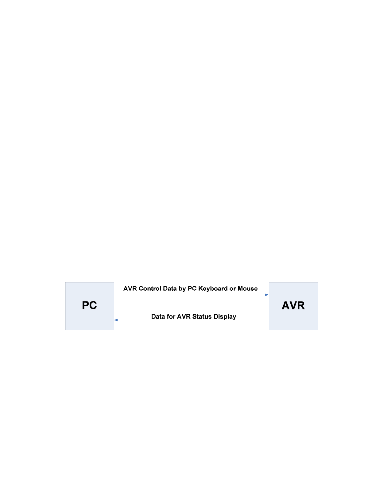
The control data is sent from the PC or control device to the AVR using commands issued
using either a PC Keyboard or Mouse or a touch screen controller and data from the AVR
with its status may be displayed on the PC or interpreted for touch screen display.
Harman Kardon AVR Products RS-232 Code Programming Information
Version 1.0 ~ 14-November-05
Page 2 of 12
Page 3

3.0 Connections and Settings
3.1 Connections
The connection between the computer and the AVR is via a two-wire connection using
standard DB-9 connections.
The connections should be made directly (“straight through”) from pin 3 (TxD) to pin 3, and
from pin 5 (GND) to pin 5. No other connections are needed, although a standard serial
connection cable with all pins connected may be used.
IMORTANT NOTE: It is essential that a standard “straight through” connection cable
be used. DO NOT use a “null modem” cable. Since the AVR cross over the pin
connections internally, the use of null modem cable will render RS-232 control
system inoperable.
3.2 RS-232 Settings
The following settings should be made on PC or control device:
Baud Rate: 38,400 bps
Data Bits: 8
Parity: No
Stop Bit: 1
Flow Control: No (off)
Command Acceptance Time: 50 ms
4.0 Data Communication Format
4.1. Transmission
Transmission Data Type Length Information Field Check Sum
Transmission recognition code is 6 bytes long ASCII code and it is used to make a
distinction between AVR Control Data being sent from PC to AVR or AVR status Data
coming from AVR to be displayed on PC. Following codes are used for this purpose:
“PCSEND”(ASCII) AVR Control Data (PC to AVR) using PC Keyboard or Mouse
“MPSEND”(ASCII) Data for AVR Status Display on PC (AVR to PC)
Harman Kardon AVR Products RS-232 Code Programming Information
Version 1.0 ~ 14-November-05
Page 3 of 12
Page 4
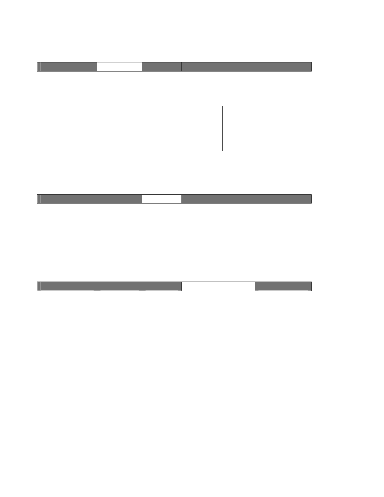
4.2 Data Type
Transmission Data Type Length Information Field Check Sum
Data Type field is a one byte long and distinguishes between different types of data being
used in protocol as explained in the following table:
Purpose Direction Value
DSP UPGRADE PC AVR 1
PC Remote Controller PC AVR 2
CPU UPGRADE PC AVR 4
Send Data from AVR AVR PC 3
4.3 Data Length
Transmission Data Type Length Information Field Check Sum
Length field is one byte long and represents length of information field. As information field
is variable depending on direction of data transfer, this field is necessary. Length field
value will be 4 if Remote Control through PC to AVR is used and the value will be 48 if
AVR status display on PC is desired.
4.4 Information Field
Transmission Data Type Length Information Field Check Sum
Information field is hex code data of either four-byte command from PC to AVR or 48-byte
hex code for AVR status display on PC. We explain both of them in detail in the following
sections:
Harman Kardon AVR Products RS-232 Code Programming Information
Version 1.0 ~ 14-November-05
Page 4 of 12
Page 5

4.4.1 Information Field Command Sequences
4.4.1.1 Command Transmission Sequence from PC to AVR
Each command consists of a four-byte hex code from the table at the end of this
document. To send a command, first find the hex code listed in the chart for the specific
function. Convert each byte to binary, and then precede each byte with a start bit (0) and
follow it with a stop bit (1). Make certain that the time for the transmission of all four bytes
does not exceed 50 ms; the AVR will interpret a time gap greater than 50 ms as the start of
a new command.
For example, to send the “80, 70, C1, 3E” hex code sequence to issue a “Mute” command,
the sequence would be as follows, including the start and stop bit after each hex code:
TOTAL STRUTCTURE FOR THE
FOUR_BYTE COMMAND
When building a sequence with multiple commands, remember to insert a sufficient time
delay so that the total time from the start of one four-byte command to the start of next four
byte command is at least 50 ms.
The protocol for code transmission does not allow for “repeat” or continuous code. Thus,
for commands (such as “Volume”) for which the button would be held down when using the
actual remote, the specific command (e. g., “Volume Up” or “Volume Down”) must be sent
individually as many times as necessary to achieve the desired effect.
The commands being sent through the RS-232 link are direct mirror images of the
commands and command sequences that would be used if you were pressing the remote
control buttons. In cases where a main command is issued first, followed by up/down or
left/right navigation to select a choice, you will need to use the specific directional
command codes for the command in use. The up/down and left/right navigation commands
are NOT universal for RS-232 link; it is crucial that you use the correct navigation
command control.
Harman Kardon AVR Products RS-232 Code Programming Information
Version 1.0 ~ 14-November-05
Page 5 of 12
Page 6

4.4.4.1 Data Sequence from AVR to PC
The following diagram shows the detail of data being sent from AVR to PC to show status
to be displayed:
4.5: Check Sums
Transmission Data Type Length Information Field Check Sum
Check sum is calculated by splitting the data into even bytes and odd bytes and calculating
two checksum bytes using them. Check sum high byte is calculated by Xor sum of even
bytes while check sum low byte is calculated by Xor sum of odd bytes.
Data[0]^Data[2]^…..Data[2n]= Check Sum[0] high byte
Data[1]^Data[3]^…..Data[2n-1]= Check Sum[1] low byte
Harman Kardon AVR Products RS-232 Code Programming Information
Version 1.0 ~ 14-November-05
Page 6 of 12
Page 7

5.0 Constructing Command Sequences
To construct command set sequences for RS-232 control, you must create a structure that
duplicates the button that you would push on remote control to issue the desired
command.
Some commands require multiple button presses, regardless of whether the command is
being sent from remote, or via RS-232 link. You should make sure that all needed
commands for desired functionality is included and the spacing between each commands
is at least 50 ms.
The command structure for RS-232 link does not accommodate “repeat” commands.
These must be issued by duplicating commands as many times as needed.
In constructing commands for Surround Select, Multi-room, Speaker Configuration, Digital
Input and Delay, the direct access setup controls for these options require that you should
first send the code that accesses the control sequence. To adjust the settings or scroll
through the menus, you must then issue the specific “Up” or “Down” commands that are
associated with the item being controlled.
For example, when changing the surround mode using the Dolby, DTS Surround, DTS
Neo:6, Logic 7 or Stereo commands, note that first command selects the mode and the
next command should select the mode choices.
6.0 Procedures for Switching AVR and PC Modes
In case of AVR Normal Mode and PC Remote Control (REMOCON), normal protocol
procedures as mentioned already will be applied. The following sections explain the other
switching modes.
6.1 Switching from PC REMOCON Mode to PC CPU Writing Mode
Step 1: User selects CPU button at the screen box of PC REMOCON. As a result, PC
sends the following command:
Command: "PCSEND" + 0x04 + 0x02 + 0x00 + 0x00 + 0x00 + 0x00
Response: No response comes from AVR
Step 2: After receiving the command from step 1, AVR will switch from normal mode to
AVR CPU writing mode and will stop sending its status information.
Step 3: User clicks the open button at the screen box of PC CPU Writing. User selects and
loads CPU HEX DATA (This HEX file has Intel-HEX format) using explorer box.
Harman Kardon AVR Products RS-232 Code Programming Information
Version 1.0 ~ 14-November-05
Page 7 of 12
Page 8

Step 4: User clicks the Start button at the screen box of PC CPU Writing. This step
creates the following protocol behind the scene:
a) Check Connection – Following command is used to check connection:
Command: 0x08 + Sync Data (0x00) X 16 + CRC (2bytes)
Response: 0x08 + CRC (2bytes)
Check CRC to make sure the message reached correctly. We have already
discussed CRC calculation method.
b) Erase Earlier Settings – Unless response is OK, continue to send this command:
Command: 0x01 + CRC (2bytes)
Response: if OK, 0x01 + CRC (2bytes)
if Error, 0x0e + CRC (2bytes)
c) Program CPU - Follow sending the required command, the command is sent
again till correct response is received:
Command: 0x03 + address (3bytes: Low, Mid, High byte in order) +
Hex Data (256byte) + CRC (2bytes)
Response: 0x03 + address (3bytes) + CRC (2bytes)
Program Control Flow is as follows:
Harman Kardon AVR Products RS-232 Code Programming Information
Version 1.0 ~ 14-November-05
Page 8 of 12
Page 9

(d) Verify that program stored in CPU - Follow sending the required command, the
command is sent again till correct response is received:
Command: 0x04 + address (3bytes: Low, Mid, High byte in sequence)
+ CRC (2 bytes)
Response: 0x04 + address (3bytes) + Hex Data (256) + CRC (2bytes)
Verify Control Flow is as follows:
(e) End CPU Writing/Work End – Following command and response are used:
Command: 0x06 + CRC (2 bytes)
Response: 0x06 + CRC (2 bytes)
(f) CutOff – Following command and response are used:
Command: 0x07 + CRC (2 bytes)
Response: 0x07 + CRC (2 bytes)
Harman Kardon AVR Products RS-232 Code Programming Information
Version 1.0 ~ 14-November-05
Page 9 of 12
Page 10

Step 5: User switches from AVR CPU writing Mode to AVR Normal Mode. User turns
the power off and then turns power on again for this purpose.
Step 6: User switches from PC CPU Writing mode to PC REMOCON mode by clicking
REMOTE button at the screen box of PC CPU Writing.
7.0 Code Tables
The following table shows four-byte hex codes to be used for Remote Control of applicable
products via the RS-232 port. Note that some features are not available on certain models.
COMMAND -> AVR 1st 2nd 3rd 4th
POWER ON 80 70 C0 3F
POWER OFF 80 70 9F 60
MUTE 80 70 C1 3E
AVR 82 72 35 CA
DVD 80 70 D0 2F
CD 80 70 C4 3B
TAPE 80 70 CC 33
VID1 80 70 CA 35
VID2 80 70 CB 34
VID3 80 70 CE 31
VID4 80 70 D1 2E
VID5 80 70 F0 0F
AM/FM 80 70 81 7E
6CH/8CH 82 72 DB 24
SLEEP 80 70 DB 24
SURR 82 72 58 A7
DOLBY 82 72 50 AF
DTS 82 72 A0 5F
DTS NEO:6 82 72 A1 5E
LOGIC7 82 72 A2 5D
STEREO 82 72 9B 64
TEST TONE 82 72 8C 73
NIGHT 82 72 96 69
1 80 70 87 78
2 80 70 88 77
3 80 70 89 76
4 80 70 8A 75
5 80 70 8B 74
6 80 70 8C 73
7 80 70 8D 72
8 80 70 8E 71
Information Field
Harman Kardon AVR Products RS-232 Code Programming Information
Version 1.0 ~ 14-November-05
Page 10 of 12
Page 11

9 80 70 9D 62
0 80 70 9E 61
TUNE UP 80 70 84 7B
TUNE DOWN 80 70 85 7A
VOL UP 80 70 C7 38
VOL DOWN 80 70 C8 37
PRESET UP 82 72 D0 2F
PRESET DOWN 82 72 D1 2E
DIGITAL 82 72 54 AB
DIGITAL UP 82 72 57 A8
DIGITAL DOWN 82 72 56 A9
FMMODE 80 70 93 6C
DELAY 82 72 52 AD
DELAY UP 82 72 8A 75
DELAY DOWN 82 72 8B 74
COM SET 82 72 84 7B
COM UP 82 72 99 66
COM DOWN 82 72 9A 65
SPEAKER 82 72 53 AC
SPEAKER UP 82 72 8E 71
SPEAKER DOWN 82 72 8F 70
CHANNEL 82 72 5D A2
RDS 82 72 DD 22
DIRECT 80 70 9B 64
CLEAR 82 72 D9 26
MEMORY 80 70 86 79
MULTIROOM 82 72 DF 20
MULTIROOM UP 82 72 5E A1
MULTIROOM DOWN 82 72 5F A0
OSD 82 72 5C A3
OSD LEFT 82 72 C1 3E
OSD RIGHT 82 72 C2 3D
SURR UP 82 72 85 7A
SURR DOWN 82 72 86 79
PRESCAN 80 70 96 69
DIMMER 80 70 DC 23
FAROUDJA 82 72 C6 39
TONE 82 72 C5 3A
Harman Kardon AVR Products RS-232 Code Programming Information
Version 1.0 ~ 14-November-05
Page 11 of 12
Page 12

8.0 Normal AVR Status Display Mode
Information Field Information Field
Data Address
0 F0 (ID code) 1bytes
1-14 FL UPPER (14byte) 14bytes
15 Reserve 1bytes
16 F1 (ID code) 1bytes
17-30 FL Down (14byte) 14bytes
31 Reserve 1bytes
32 F2 (ID code) 1bytes
33-46 FL ICON (14byte) 14bytes
47 Reserve 1bytes
AVR MODE -> PC
Data Value
Harman Kardon AVR Products RS-232 Code Programming Information
Version 1.0 ~ 14-November-05
Page 12 of 12
 Loading...