

Page 1

Harman Kardon Service Manual
CONTENTS
BILL OF MATERIALS, AVR 270 76
PRODUCT SHEETS WITH SPECS 2
AVR 370 125 watt 7.1 CHANNEL A/V RECEIVER
AVR 270 100 watt 7.1 CHANNEL A/V RECEIVER
OWNER’S MANUAL 6
PACKAGE DRAWINGS 69
EXPLODED VIEW AND PARTS 71
DISASSEMBLY 73
BIAS ADJUSTMENT 75
Released EU2012 Harman Consumer Group, Inc. Rev 0, 11/2012
8500 Balboa Boulevard
Northridge, California 91329
BILL OF MATERIALS, AVR 270 126
BLOCK DIAGRAMS 161
WIRING DIAGRAM 163
SCHEMATIC DIAGRAMS 164
Page 2

AVR 270
7.1-channel network-connected audio/video receiver with 100 watts per channel output. Featuring Apple AirPlay,
High-Denition Dolby
®
and DTS® surround-sound modes, multizone functionality and 4K video support.
Experience entertainment like you never thought possible at
home. The Harman Kardon® AVR 270 delivers high-denition video
along with crisp, detailed 7.1-channel surround sound.
This 100-watt, network-connected audio/video receiver features
eight HDMI® inputs with 3D and Audio Return Channel, including
one on the front panel. Built-in DLNA Certied® 1.5 Ethernet
connectivity and Apple AirPlay not only keep you connected to all
your sources, but enable you to output them in the most realistic
quality possible. Get the most out of your home theatre. Experience
the Harman Kardon AVR 270.
Movie-theatre-quality viewing
• HDMI with 3D, Audio Return Channel, CEC and Deep Colour
• Powerful 7.1-channel surround system
®
• Dolby
• Dolby Volume (for constant audio level regardless of changes
TrueHD and DTS-HD Master Audio™ decoding
in program content)
Supreme connectivity
• DLNA Certied 1.5 connectivity
• AirPlay-enabled
• 4K video pass-through and upscaling
• Control applications for Apple and Android
A new level in home entertainment.
™
products
Page 3

SPECIFICA TIONS
AVR 270
What’s included:
• 1 AVR 270 A/V receiver
• IR remote control with batteries
• 1 Detachable IEC power cord
• 1 Quick Start Guide
• 1 AM loop antenna
• 1 FM antenna
• Microphone for EzSet/EQ
™
room-correction system
Audio Section
• Stereo mode continuous average power: 100 watts/ch, 20Hz – 20kHz,
<0.07% THD, both channels driven @ 8 ohms, 6-ohm certied
• Multichannel power: 100 watts/ch, 20Hz – 20kHz, <0.07% THD,
two channels driven @ 8 ohms, 6-ohm certied
• Bandwidth @ 1W (+0dB/–3dB): 10Hz – 130kHz
• Input sensitivity/impedance (line-in): 200mV/47k ohms
• Signal-to-noise ratio (IHF-A): 100dB
• Adjacent channel separation
Dolby Pro Logic® I/II: 40dB
Dolby Digital: 55dB
DTS: 55dB
• High instantaneous current capability (HCC): ±35 amps
• Transient intermodulation distortion (TIM): Unmeasurable
• Slew rate: 40V/μsec
FM Tuner Section
• Frequency range: 87.5MHz–108.0MHz
• Usable sensitivity (IHF): 1.3μV/13.2dBf
• Signal-to-noise ratio (mono/stereo): 70dB/68dB
• Distortion (mono/stereo): 0.2%/0.3%
• Stereo separation: 40dB @ 1kHz
• Selectivity (±400kHz): 70dB
• Image rejection: 80dB
• IF rejection: 90dB
• 100 watts per channel
• Eight HDMI inputs with 3D and Audio Return Channel,
including one on the front panel, and two HDMI inputs
• 7.1-channel surround sound
• Dolby TrueHD and DTS-HD Master Audio decoding
• Multizone functionality
• Dolby Volume
AM Tuner Section
• Frequency range: 520kHz – 1.620kHz
• Signal-to-noise ratio: 45dB
• Usable sensitivity (loop): 500μV
• Distortion (1kHz): 50%, mod 0.8%
• Selectivity (±10kHz): 30dB
Video Section
• Television format: PAL, NTSC
• Input level/impedance: 1Vp-p/75 ohms
• Output level/impedance: 1Vp-p/75 ohms
• Video frequency response (composite video): 10Hz – 8MHz (–3dB)
• HDMI: 3D, Audio Return Channel, CEC and Deep Colour
General
• Power requirement: AC 230V/50–60Hz
• Power consumption: 120W idle; 1405W maximum
• Dimensions (W x H x D): 440mm x 165mm x 382mm
(17-5/16" x 6-1/2" x 15")
• Weight: 7.7kg (16.9 lb)
Available downloads
• Control applications for Apple products
• Control applications for Android products
• HARMAN Media Manager
• DLNA Certied 1.5 connectivity
• AirPlay audio streaming
• High-denition user interface
• 4K video pass-through and upscaling
• EzSet/EQ
™
technology (maximises sonic performance)
• Free downloadable control applications for smartphones
and tablets with Android applications or iOS software
HARMAN International Industries, Incorporated
8500 Balboa Boulevard, Northridge, CA 91329 USA
© 2012 HARMAN International Industries, Incorporated. All rights reserved.
Harman Kardon and Logic 7 are trademarks of HARMAN International Industries, Incorporated, registered in the United States and/or other countries. The “beautiful/sound” logo, EzSet/EQ and the EzSet/EQ logo are trademarks of HARMAN International Industries, Incorporated. AirPlay, the AirPlay logo, Apple, the Apple App Store logo, iPad,
iPhone, iPod and the “Made for iPod, iPhone and iPad” logo are trademarks of Apple Inc., registered in the U.S. and other countries. “Made for iPod,” “Made for iPhone,” and “Made for iPad” mean that an electronic accessory has been designed to connect specically to iPod, iPhone, or iPad, respectively, and has been certied by the
developer to meet Apple performance standards. Apple is not responsible for the operation of this device or its compliance with safety and regulatory standards. Please note that the use of this accessory with iPod, iPhone, or iPad may affect wireless performance. Android and the “Google play” logo are trademarks of Google Inc. Use of this
trademark is subject to Google Permissions. DLNA Certied and the “DLNA Certied” logo are registered trademarks of the Digital Living Network Alliance. Dolby, the Dolby logos and Pro Logic are registered trademarks of Dolby Laboratories. DTS is a registered trademark of DTS, Inc. DTS-HD Master Audio and its logo are trademarks of
DTS, Inc. HDMI and its logo are registered trademarks of HDMI Licensing, LLC in the United States and/or other countries. The USB logo is a trademark of the USB Implementers Forum, Inc. The “vTuner” logo is a trademark of Nothing Else Matters Software, Ltd.
Features, specications and appearance are subject to change without notice.
www.harmankardon.com
Page 4

AVR 370
7.2-channel wireless network-connected audio/video receiver with 125 watts per channel output. Featuring Apple AirPlay,
High-Denition Dolby
®
and DTS® surround-sound decoding, multizone functionality and 4K video scaling.
Experience the pinnacle of home entertainment. The Harman Kardon®
AVR 370 delivers high-denition video and 125 watts per channel of
7.2-channel surround sound so realistically that the experience of sitting
down and watching a movie seems anything but passive. Eight HDMI®
inputs, with 3D and Audio Return Channel, including one on the front
panel, keep you connected to all your digital components, playing them
back in rich, vivid quality. Built-in Wi-Fi® networking and Apple AirPlay
software give you wireless access to all the media les on your iPod,
smartphone, tablet and computer with remarkable. Elevate your home
theater experience to its highest level.
Cinematic experience
• HDMI with 3D, Audio Return Channel, CEC
and Deep Colour
• Powerful 7.2-channel surround system
®
• Dolby
TrueHD and DTS-HD Master Audio™
decoding
Supreme connectivity
• Built-in Wi-Fi networking
• AirPlay-enabled
• 4K video pass-through and scaling
• Control applications for Apple and Android
The AVR cinephiles dream of.
™
products
Page 5

SPECIFICA TIONS
AVR 370
What’s included:
• 1 AVR 370 A/V receiver
• Backlit main remote control
with batteries
• Zone II remote with batteries
• Microphone for EzSet/EQ room-
correction system
• 1 Detachable IEC power cord
• 1 Quick Start Guide
• 1 AM loop antenna
• 1 FM antenna
Audio Section
• Stereo mode continuous average power: 125 watts/ch, 20Hz – 20kHz,
<0.07% THD, both channels driven @ 8 ohms, 6-ohm certied
• Multichannel power: 125 watts/ch, 20Hz – 20kHz, <0.07% THD,
two channels driven @ 8 ohms, 6-ohm certied
• Bandwidth @ 1W (+0dB/–3dB): 10Hz – 130kHz
• Input sensitivity/impedance (line-in): 200mV/47k ohms
• Signal-to-noise ratio (IHF-A): 100dB
• Adjacent channel separation
Dolby Pro Logic® I/II: 40dB
Dolby Digital: 55dB
DTS: 55dB
High instantaneous current capability (HCC): ±45 amps
Transient intermodulation distortion (TIM): Unmeasurable
Slew rate: 40V/μsec
FM Tuner Section
• Frequency range: 87.5MHz – 108.0MHz
• Usable sensitivity (IHF): 1.3μV/13.2dBf
• Signal-to-noise ratio (mono/stereo): 70dB/68dB
• Distortion (mono/stereo): 0.2%/0.3%
• Stereo separation: 40dB @ 1kHz
• Selectivity (±400kHz): 70dB
• Image rejection: 80dB
• IF rejection: 90dB
• 125 watts per channel
• Eight HDMI inputs with 3D and Audio Return Channel
including one on the front panel, and two HDMI outputs
• 7.2-channel surround sound
• Dolby TrueHD and DTS-HD Master Audio decoding
• Multizone functionality
• Built-in Wi-Fi and AirPlay audio streaming
• DLNA Certied
®
1.5 connectivity
AM Tuner Section
• Frequency range: 520kHz – 1,620kHz
• Signal-to-noise ratio: 45dB
• Usable sensitivity (loop): 500μV
• Distortion (1kHz): 50%, mod 0.8%
• Selectivity (±10kHz): 30dB
Video Section
• Television format: PAL, NTSC
• Input level/impedance: 1Vp-p/75 ohms
• Output level/impedance: 1Vp-p/75 ohms
• Video frequency response (composite video): 10Hz – 8MHz (–3dB)
• HDMI: 3D, Audio Return Channel, CEC and Deep Colour
General
• Power requirement: AC 230V/50 – 60Hz
• Power consumption: 120W idle; 1,405W maximum (7 channels driven)
• Dimensions (W x H x D): 440mm x 165mm x 382mm
(17-5/16" x 6-1/2" x 15")
• Weight: 8kg (17.6 lb)
• High-denition user interface
• 4K video pass-through and scaling
• Full preamp outputs for use with external power ampliers
• Complete Zone 2 audio system with remote control
• EzSet/EQ
™
technology maximizes sonic performance
• Free downloadable control applications for smartphones
and tablets with iOS software and Android application
HARMAN International Industries, Incorporated
8500 Balboa Boulevard, Northridge, CA 91329 USA
© 2012 HARMAN International Industries, Incorporated. All rights reserved.
Harman Kardon and Logic 7 are trademarks of HARMAN International Industries, Incorporated, registered in the United States and/or other countries. The “beautiful/sound” logo, EzSet/EQ and the EzSet/EQ logo are trademarks of HARMAN International Industries, Incorporated. AirPlay, the AirPlay logo, Apple, the Apple App Store logo, iPad,
iPhone, iPod and the “Made for iPod, iPhone and iPad” logo are trademarks of Apple Inc., registered in the U.S. and other countries. “Made for iPod,” “Made for iPhone,” and “Made for iPad” mean that an electronic accessory has been designed to connect specically to iPod, iPhone, or iPad, respectively, and has been certied by the
developer to meet Apple performance standards. Apple is not responsible for the operation of this device or its compliance with safety and regulatory standards. Please note that the use of this accessory with iPod, iPhone, or iPad may affect wireless performance. Android and the “Google play” logo are trademarks of Google Inc. Use of
this trademark is subject to Google Permissions. DLNA Certied and the “DLNA Certied” logo are registered trademarks of the Digital Living Network Alliance. Dolby, the Dolby logos and Pro Logic are registered trademarks of Dolby Laboratories. DTS is a registered trademark of DTS, Inc. DTS-HD Master Audio and the “DTS-HD Master
Audio” logo are trademarks of DTS, Inc. HDMI and the “HDMI” logo are registered trademarks of HDMI Licensing, LLC in the United States and/or other countries. The USB logo is a trademark of the USB Implementers Forum, Inc. The “vTuner” logo is a trademark of Nothing Else Matters Software, Ltd. Wi-Fi and the Wi-Fi CERTIFIED logo are
registered trademarks of the Wi-Fi Alliance. Features, specications and appearance are subject to change without notice.
www.harmankardon.com
Page 6

AVR 3700, AVR 370
AVR 2700, AVR 270
Audio/video receiver
Owner’s Manual
Page 7

AVR
Table of Contents
INTRODUCTION 3
SUPPLIED ACCESSORIES 3
IMPORTANT SAFETY INFORMATION 3
PLACE THE RECEIVER 3
FRONT-PANEL CONTROLS 4
REAR-PANEL CONNECTORS 6
SYSTEM REMOTE CONTROL FUNCTIONS 8
ZONE 2 REMOTE CONTROL FUNCTIONS 10
INTRODUCTION TO HOME THEATER 12
TYPICAL HOME THEATER SYSTEM 12
MULTICHANNEL AUDIO 12
SURROUND MODES 12
PLACE YOUR SPEAKERS 13
PLACING THE LEFT, CENTER AND RIGHT SPEAKERS 13
PLACING THE SURROUND SPEAKERS IN A
5.1-CHANNEL SYSTEM 13
PLACING THE SURROUND SPEAKERS IN A
7.1-CHANNEL SYSTEM 13
PLACING FRONT HEIGHT SPEAKERS IN A
7.1-CHANNEL SYSTEM 13
PLACING THE SUBWOOFER 13
TYPES OF HOME THEATER SYSTEM CONNECTIONS 14
SPEAKER CONNECTIONS 14
SUBWOOFER CONNECTIONS 14
SOURCE DEVICE CONNECTIONS 14
VIDEO CONNECTIONS 15
RADIO CONNECTIONS 16
NETWORK CONNECTOR 16
USB PORT 16
RS-232 CONNECTOR 16
MAKING CONNECTIONS 17
CONNECT YOUR SPEAKERS 17
CONNECT YOUR SUBWOOFER 17
CONNECT YOUR TV OR VIDEO DISPLAY 17
CONNECT YOUR AUDIO AND VIDEO SOURCE DEVICES 18
CONNECT TO USB AND iOS DEVICES 20
CONNECT TO YOUR HOME NETWORK 20
CONNECT THE RADIO ANTENNAS 20
INSTALL A MULTIZONE SYSTEM 21
CONNECT IR EQUIPMENT (AVR 3650/AVR 365 ONLY) 22
CONNECT THE TRIGGER OUTPUT 23
CONNECT TO AC POWER 23
SET UP THE REMOTE CONTROL 24
INSTALL THE BATTERIES IN THE REMOTE CONTROL 24
PROGRAM THE REMOTE TO CONTROL
YOUR SOURCE DEVICES AND TV 24
SET UP THE AVR 26
TURN ON THE AVR 26
USING THE ON-SCREEN MENU SYSTEM 25
CONFIGURE THE AVR FOR YOUR SPEAKERS 26
SET UP YOUR SOURCES 27
SET UP THE NETWORK 28
OPERATING YOUR AVR 30
CONTROLLING THE VOLUME 30
MUTING THE SOUND 30
DOLBY® VOLUME 30
LISTENING THROUGH HEADPHONES 30
SELECTING A SOURCE 31
LISTENING TO FM AND AM RADIO 30
LISTENING TO MEDIA ON A USB DEVICE 32
LISTENING TO AN iPod/iPhone/iPad DEVICE 32
LISTENING TO vTUNER (INTERNET RADIO) 33
LISTENING TO MEDIA VIA YOUR HOME NETWORK 33
SELECTING A SURROUND MODE 34
AUDIO EFFECTS 34
VIDEO MODES 34
ADVANCED FUNCTIONS 35
AUDIO PROCESSING AND SURROUND SOUND 35
VIDEO PROCESSING 36
MANUAL SPEAKER SETUP 38
LISTENING IN ZONE 2 41
SYSTEM SETTINGS 42
SETTINGS LOCK 43
ADVANCED REMOTE CONTROL PROGRAMMING 44
RECORDING 44
SLEEP TIMER 44
RESETTING THE REMOTE 44
PROCESSOR RESET 44
TROUBLESHOOTING 45
SPECIFICATIONS 46
APPENDIX 47
2
Page 8

AVR
Introduction, Supplied Accessories,
Important Safety Information and Place the Receiver
ENGLISH
Introduction
Thank you for choosing this Harman Kardon product!
For more than fifty years, the Harman Kardon mission has been to share a passion for music
and entertainment, using leading-edge technology to achieve premium performance.
Sidney Harman and Bernard Kardon invented the receiver, a single component designed
to simplify home entertainment without compromising performance. Over the years,
Harman Kardon products have become easier to use, while offering more features and
sounding better than ever.
The AVR 3700, AVR 2700, AVR 370 and AVR 270 7.1-channel digital audio/video receivers
continue this tradition with some of the most advanced audio and video processing
capabilities yet, and a wealth of listening and viewing options.
To obtain the maximum enjoyment from your new receiver, please read this manual and
refer back to it as you become more familiar with its features and their operation.
If you have any questions about this product, its installation or its operation, please
contact your Harman Kardon retailer or custom installer, or visit the Web site at
www.harmankardon.com.
Supplied Accessories
The following accessory items are supplied with your receiver. If any of these items are
missing, please contact your Harman Kardon dealer or Harman Kardon customer service
at www.harmankardon.com.
• System remote control
• Zone 2 remote control (AVR 3700/AVR 370 only)
• EzSet/EQ™ microphone
• AM loop antenna
• FM wire antenna
• Six AAA batteries (AVR 3700/AVR 370); four AAA batteries (AVR 2700/AVR 270)
• AC power cord
IMPORTANT SAFETY INFORMATION
Verify Line Voltage Before Use
The AVR 3700 and AVR 2700 have been designed for use with 120-volt AC current.
The AVR 370 and AVR 270 have been designed for use with 220 – 240-volt AC current.
Connection to a line voltage other than that for which your receiver is intended can create
a safety and fire hazard and may damage the unit. If you have any questions about the
voltage requirements for your specific model, or about the line voltage in your area,
contact your selling dealer before plugging the unit into a wall outlet.
Do Not Use Extension Cords
To avoid safety hazards, use only the power cord supplied with your unit. We do not
recommend that extension cords be used with this product. As with all electrical devices,
do not run power cords under rugs or carpets, or place heavy objects on them. Damaged
power cords should be replaced immediately by an authorized service center with a cord
meeting factory specifications.
Handle the AC Power Cord Gently
When disconnecting the power cord from an AC outlet, always pull the plug; never pull
the cord. If you do not intend to use your receiver for any considerable length of time,
disconnect the plug from the AC outlet.
Do Not Open the Cabinet
There are no user-serviceable components inside this product. Opening the cabinet may
present a shock hazard, and any modification to the product will void your warranty.
If water or any metal object such as a paper clip, wire or staple accidentally falls inside
the unit, disconnect it from the AC power source immediately, and consult an authorized
service center.
CATV or Antenna Grounding (AVR3700/AVR 2700)
If an outside antenna or cable system is connected to this product, be certain that it is
grounded so as to provide some protection against voltage surges and static charges.
Section 810 of the United States National Electrical Code, ANSI/NFPA No. 70-1984,
provides information with respect to proper grounding of the mast and supporting
structure, grounding of the lead-in wire to an antenna discharge unit, size of grounding
conductors, location of antenna discharge unit, connection to grounding electrodes and
requirements of the grounding electrode.
NOTE TO CATV SYSTEM INSTALLER: This reminder is provided to call the CATV (cable TV)
system installer’s attention to article 820-40 of the NEC, which provides guidelines for
proper grounding and, in particular, specifies that the cable ground shall be connected
to the grounding system of the building, as close to the point of cable entry as possible.
Place the Receiver
• Place the receiver on a firm and level surface. Be certain that the surface and any
mounting hardware can support the AVR’s weight.
• Provide proper space above and below the AVR for ventilation. Recommended
clearance distances are 30cm above the unit, 30cm behind the unit and 30cm on
each side of the unit.
• If you install the AVR in a cabinet or other enclosed area, provide cooling air within
the cabinet. Under some circumstances, a fan may be required.
• Do not obstruct the ventilation slots on the top of the receiver or place objects
directly over them.
• Do not place the receiver directly on a carpeted surface.
• Do not place the receiver in moist or humid locations, in extremely hot or cold
locations, in areas near heaters or heat registers, or in direct sunlight.
3
Page 9
AVR
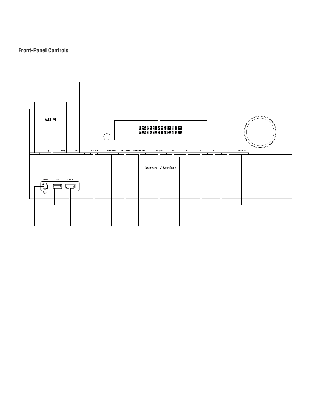
Front-Panel Controls
Front-Panel Controls
Power
Indicator
Power
Button
USB
Port
Setup
Button
Info
Button
Resolution
Button
IR
Sensor
Video
Modes
Button
Message
Display
Back/Exit
Button
OK
Button
Volume
Knob
Source List
Button
Headphone Jack/
EzSet/EQ
Mic Input
®
Front
HDMI
Input Connector
Audio
Effects
Button
Surround
Modes
Button
Left/Right
Buttons
Up/Down
Buttons
4
Page 10

AVR
Front-Panel Controls
ENGLISH
Front-Panel Controls, continued
Power indicator/Power button: The AVR has four different power modes:
• Off (Power indicator not illuminated): When the rear-panel Main Power switch is in
the Off position or the power cord is unplugged the AVR is off and will not respond to
any commands. Plugging the power cord into a live AC outlet and setting the Main
Power switch in the On position will put the AVR into the Eco Standby mode.
• Eco Standby (Power indicator glows solid amber): The Eco Standby mode minimizes
energy consumption when you're not using the AVR. When the AVR is in Eco Standby,
it will not automatically turn on or play audio in response to an AirPlay signal from
a networked device. When the AVR is in Eco Standby, pressing the Power button
turns it on. To put the AVR into Eco Standby when it is on, press the Power button
for more than three seconds. NOTE: The AVR will not automatically enter the Eco
Standby mode.
• Standby (Power indicator glows solid amber): The Standby mode mutes the AVR
and shuts off its front-panel display, but allows the AVR to automatically turn on and
play audio in response to an AirPlay signal from a networked device. See Listening
to Media via AirPlay, on page XX, for more information. When the AVR is in Standby,
pressing the Power button turns it on. To put the AVR into Standby when it is on, press
the Power button for less than three seconds. NOTE: The AVR will automatically enter
the Standby mode whenever no control buttons have been pressed and no audio
signal has been present for 30 minutes.
• On (Power indicator glows solid white): When the AVR is on it is fully operational.
IMPORTANT NOTE: If the PROTECT message ever appears on the AVR’s front-
panel message display, turn off the AVR and unplug it from the AC outlet.
Check all speaker wires for a possible short-circuit (the “+” and “–” conductors
touching each other or both touching the same piece of metal). If a short-circuit is not
found, bring the unit to an authorized Harman Kardon service center for inspection
and repair before using it again.
IMPORTANT NOTE: If you set the AVR’s video output resolution higher than
the capabilities of the actual connection between the AVR and your TV or video
display, you will not see a picture. If you are using the composite video connection
from the AVR to your TV (see Connect Your TV or Video Display, on page 17),
press the Resolution button and use the Up/Down and OK buttons to change the
resolution to 480i.
Audio Effects button: Press this button to access the Audio Effects submenu, which
allows you to adjust the AVR’s tone controls and other audio controls. See Set Up Your
Sources, on page 26, for more information.
Video Modes button: Press this button for direct access to the Video Modes submenu,
which contains settings you can use to improve the video picture. Use the OK button
to scroll through the different modes, and use the Up/Down and Left/Right buttons to
make adjustments within each mode. See Set Up Your Sources, on page 26, for more
information.
Surround Modes button: Press this button to select a listening mode. The Surround
Modes menu will appear on screen, and the menu line will appear in the front-panel
display. Use the Up/Down buttons to change the surround-mode category and the Left/
Right buttons to change the surround mode for that category. See Set Up Your Sources,
on page 26, for more information.
Back/Exit button: Press this button to return to the previous menu or to exit the menu
system.
Left/Right buttons: Use these buttons to navigate the AVR’s menus.
OK button: Press this button to select the currently highlighted item.
Up/Down buttons: Use these buttons to navigate the AVR’s menus.
Source List button: Press this button to select a source device to watch/listen to. Use
the Up/Down buttons to scroll through the source-device list, and press the OK button to
select the source being displayed.
Setup button: Press this button to access the AVR’s main menu.
Info button: Press this button to access the AVR’s Source submenu, which contains the
settings for the source currently playing. Use the Up/Down buttons to scroll through the
different settings.
Message display: Various messages appear in this two-line display in response to
commands and changes in the incoming signal. In normal operation, the current source
name appears on the upper line, while the surround mode is displayed on the lower line.
When the on-screen display menu system (OSD) is in use, the current menu settings appear.
IR sensor: This sensor receives infrared (IR) commands from the remote control. It is
important to ensure that the sensor is not blocked. If covering the IR sensor is unavoidable
(such as when the receiver is installed inside of a cabinet), connect an optional infrared
receiver to the Remote IR In connector on the AVR’s rear panel.
Volume knob: Turn this knob to raise or lower the volume.
Headphone jack/EzSet/EQ Mic input: Connect a 1/4" stereo headphone plug to this
jack for private listening. This jack is also used to connect the supplied microphone for
the EzSet/EQ procedure described in Configure the AVR For Your Speakers, on page XX.
USB port: You can use this port to perform software upgrades that may be offered in the
future. Do not connect a storage device, peripheral product or a PC here, unless you are
instructed to do so as part of an upgrade procedure.
HDMI (High-Definition Multimedia Interface
HDMI-capable source component that will be used only temporarily, such as a camcorder
or game console, here.
Resolution button: Press this button to access the AVR’s video output resolution setting:
480i, 480p, 720p, 1080i, 1080p or 1080p/24Hz. Use the Up/Down and OK buttons to
change the setting.
®
) Front Input connector: Connect an
Page 11
AVR
Rear-Panel Connectors
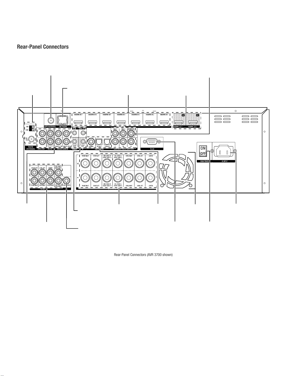
Rear-Panel Connectors (AVR 3700 shown)
Rear-Panel Connectors
Wi-Fi Antenna Connector
(AVR 3700/AVR 370)
Radio Antenna
Connectors
Network
Connector
HDMI Output
Connectors
Analog Video
Connectors
HDMI Input
Connectors
Analog Audio
Connectors
Pre-Out Connectors
(AVR 3700/AVR 370)
IR and Trigger
Connectors
Subwoofer
Connector
Speaker
Connectors
Digital Audio
Connectors
RS-232
Connector
Fan
Vents
AC Input
Connector
Main Power
Switch
6
Page 12
AVR
Rear-Panel Connectors
ENGLISH
Rear-Panel Connectors, continued
Radio Antenna connectors: Connect the supplied AM and FM antennas to their
respective terminals for radio reception.
®
Wi-Fi
Antenna connector (AVR 3700/AVR 370): If your home network is Wi-Fi,
connect the supplied Wi-Fi antenna here to enjoy Internet radio and content from DLNA®compatible devices that are connected to the network. You do not need to make a wired
network connection.
Network connector: If your home network is wired, use a Cat. 5 or Cat. 5E Ethernet
cable (not supplied) to connect the AVR’s Network connector to your home network to
enjoy Internet radio and content from DLNA-compatible devices that are connected to the
network. See Connect to Your Home Network, on page XX, for more information.
®
HDMI
Input connectors: An HDMI connection transmits digital audio and video signals
between devices. If your source devices have HDMI connectors, using them will provide
the best possible video and audio performance quality. Since the HDMI cable carries
both digital video and digital audio signals, you do not have to make any additional audio
connections for devices you connect via the HDMI connection. See Connect Your Audio
and Video Source Devices, on page XX, for more information.
HDMI Output connectors: If your TV has an HDMI connector, use an HDMI cable (not
included) to connect it to the AVR’s HDMI Out connector. The AVR will automatically
transcode component and composite video input signals to the HDMI format (upscaling
to as high as 1080p), so you do not need to make any other connections to your TV from
the AVR or from any video source devices you connect to the AVR. NOTE: The AVR 3700
and AVR 370 have two HDMI Out connectors.
Notes on using the HDMI Output connector:
• When connecting a DVI-equipped display to the HDMI Out connector, use an
HDMI-to-DVI adapter and make a separate audio connection.
• Make sure the HDMI-equipped display is HDCP (High-bandwidth Digital Content
Protection)-compliant. If it isn’t, do not connect it via an HDMI connection; use an
analog video connection instead and make a separate audio connection.
Analog Video connectors: The following Analog Video connectors are provided:
• Composite Video Input connectors: Use composite video connectors for video
source devices that don’t have HDMI or component video connectors. You will also
need to make an audio connection from the source device to the AVR. See Connect
Your Audio and Video Source Devices, on page 18, for more information.
• Component Video Input connectors: If any of your video source devices have
component video connectors (and do not have HDMI connectors), using the
component video connectors will provide superior video performance. You will also
need to make an audio connection from the device to the receiver. See Connect Your
Audio and Video Source Devices, on page 18, for more information.
• Composite Video Monitor Out connector: If your TV or video display does not
have an HDMI connector, use a composite video cable (not included) to connect the
AVR’s Composite Video Monitor Out connector to your TV ’s composite video input.
NOTE: The HDMI connection to your TV is preferred. If you use the composite video
connection to your TV, you will not be able to view the AVR’s on-screen menus.
Analog Audio connectors: The following analog audio connectors are provided:
• Analog Audio Input connectors: Use the AVR’s Analog Audio Input connectors for
source devices that don’t have HDMI or digital audio connectors. See Connect Your
Audio and Video Source Devices, on page XX, for more information.
• Analog Rec[ord] Out connectors: Connect this analog audio output to the analog
audio input of a recording device. A signal is available at this output whenever an
analog audio source is playing.
• Zone 2 Out connectors: Connect these jacks to an external amplifier to power the
speakers in the remote zone of a multizone system.
Pre-Out connectors (AVR 3700/AVR 370): Connect these jacks to external amplifiers if
more power is desired. The function of the Surround Back/Front Height/Zone 2 connectors
is determined by the setting you make for the Assigned Amp. See Manual Speaker Setup:
Number of Speakers, on page XX, for more information.
Subwoofer connector: Connect this jack to a powered subwoofer with a line-level input.
See Connect Your Subwoofer, on page XX, for more information. NOTE: The AVR 3700 and
AVR 370 have two subwoofer connectors.
IR and Trigger connectors: The following IR and trigger connectors are provided:
• IR Remote In/Out connectors: When the IR sensor on the front panel is blocked
(such as when the AVR is installed inside a cabinet), connect an optional IR receiver
to the IR Remote In jack. The IR Remote Out jack may be connected to the IR input of
a compatible product to enable remote control through the AVR.
• Zone 2 IR Input connector: Connect a remote IR receiver located in Zone 2 of a
multizone system to this jack to control the AVR (and any source devices connected
to the Remote IR Output connector) from the remote zone.
• 12V Trigger connector: This connector provides 12V DC whenever the AVR is on. It
can be used to turn on and off other devices such as a powered subwoofer.
Speaker connectors: Use two-conductor speaker wire to connect each set of terminals
to the correct speaker. See Connect Your Speakers, on page XX, for more information.
NOTE: The Assigned Amp speaker connectors are used for the surround back
channels in a 7.1- channel home theater, or you can reassign them to a remote room
for multizone operation or to front height channels for Dolby® Pro Logic IIz operation.
See Place Your Speakers, on page XX, for more information.
Digital Audio connectors: If your non-HDMI source devices have digital outputs,
connect them to the AVR’s digital audio connectors. NOTE: Make only one type of digital
connection (HDMI, optical or coaxial) from each device. See Connect Your Audio and Video
Source Devices, on page XX, for more information.
RS-232 connector: This connector is used to connect to external control hardware.
Consult a certified professional installer for more information.
Fan Vents: These vents are used by the AVR’s fan to cool the system. Maintain a
clearance of at least three inches (75mm) from the nearest surface to avoid overheating
the unit. It is normal for the fan to remain off at most normal volume levels. An automatic
temperature sensor turns the fan on only when it is needed.
IMPORTANT NOTE: Never block the fan vents. Doing so could allow the AVR to
overheat to dangerous levels.
Main Power switch: This mechanical switch turns the AVR’s power supply on or off. It is
usually left on, and it cannot be turned on or off using the remote control.
AC Input connector: After you have made and verified all other connections, plug the
supplied AC power cord into this receptacle and into an unswitched wall outlet.
7
Page 13
AVR
System Remote Control Functions
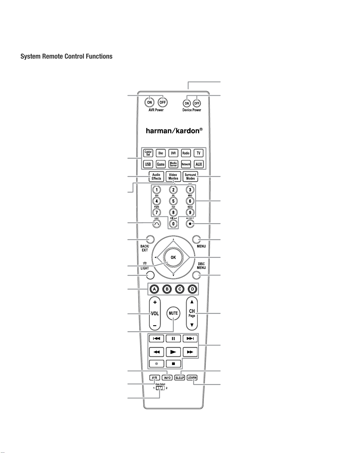
System Remote Control Functions
IR Transmitter
AVR Power On/Off
Buttons
Source Selector
Buttons
Audio Effects
Button
Video Modes
Button
Last Channel
Button
Back/Exit
Button
OK Button
Backlight Button
(AVR 3700/AVR 370)
Device Power
On/Off Buttons
Surround Modes
Button
Number
Buttons
Activity Button
Menu Button
Up/Down/Left/Right
Buttons
Disc Menu
Button
8
A/B/C/D Buttons
Volume Up/Down
Buttons
Mute Button
Info Button
AVR Button
Zone Selector
Switch
Channel Up/Down and
Page Buttons
Transport Control
Buttons
Sleep Button
Learn Button
(AVR 3700/AVR 370)
Page 14

AVR
System Remote Control Functions
ENGLISH
System Remote Control Functions, continued
In addition to controlling the AVR, the AVR remote is capable of controlling eight other
devices, including an iPod/iPhone device connected to the AVR’s front-panel USB port.
During the installation process, you may program the codes for each of your source
components into the remote. (See Program the Remote to Control Your Source Devices
and TV, on page 23, for programming information.) To operate a component, press its
Source Selector button to change the remote’s control mode.
A button’s function depends on which component is being controlled. See Table A13 in
the Appendix for listings of the functions for each type of component. Most of the buttons
on the remote have dedicated functions, although the precise codes transmitted vary
depending on the specific device being controlled. Due to the wide variety of functions
for various source devices, we have included only a few of the most-often used functions
on the remote: alphanumeric keys, transport controls, television-channel control, menu
access and power on and off. Buttons dedicated to the AVR – AVR Power On/Off, Audio
Effects, Video Modes, Surround Modes, Volume, Mute and Sleep Settings – are available
at any time, even when the remote is controlling another device.
AVR Power On/Off buttons: Press these buttons to turn the AVR on and off. The Main
Power switch on the AVR’s rear panel must be on for this button to work.
IR Transmitter: As buttons are pressed on the remote, infrared codes are emitted
through this opening.
Device Power On/Off buttons: Press a device’s Source Selector button, then press
these buttons to turn the device on and off.
Source Selector buttons: Press one of these buttons to select a source device, e.g.,
Disc, Cable/Sat, Radio, etc. This action will also turn on the AVR and switch the remote’s
control mode to operate the selected source device.
• The first press of the Radio button switches the AVR to the last-used tuner band (AM
or FM). Each successive press changes the band.
• The first press of the USB button switches the AVR to the last-used source (USB or
iPod). Each successive press cycles between the two sources.
• The first press of the Network button switches the AVR to the last-used source
(Network or vTuner). Each successive press cycles between the two sources.
Audio Effects button: Press this button to access the Audio Effects submenu, which
allows adjustment of the AVR’s tone and other audio controls. See the Set Up Your
Sources section, on page 26, for more information.
Video Modes button: Press this button for direct access to the Video Modes submenu,
which contains picture adjustments you can use after you have adjusted the picture
settings on your TV or video display. See the Advanced Functions section, on page 33,
for more information.
Surround Modes button: Press this button to access the Surround Modes submenu.
Select a surround-mode category: Auto Select, Virtual Surround, Stereo, Movie, Music or
Game. When you select the category, it is highlighted and the surround mode changes.
To change the surround mode for the selected category, press the OK button when the
menu line is highlighted and use the Up/Down buttons to select one of the available
surround-mode options. Press the OK button; or press the Back/Exit button to exit the
Surround Modes menu and display the next higher menu in the hierarchy. See the
Advanced Functions section, on page 33, for more information.
Number buttons: Use these buttons to enter numbers for radio-station frequencies or
to select station presets.
Last Channel button: When controlling a cable, satellite or HDTV set-top box or a TV,
press this button to return to the previous television channel.
Activity button: With this button you can program the remote to store up to 11 different
Macros (Activities). (A Macro is a series of commands that are transmitted by a single
button press.) Execute a Macro by pressing this button, followed by the Number button
(or the AVR Power On button) into which you programmed the Macro. See Programming
Macro (Activity) Commands, on page 41, for more information.
Back/Exit button: Press this button to return to the previous menu or to exit the menu
system.
Menu button: This button is used within the tuner menus and an iPod connected to the
AVR’s front-panel USB port, and is also used to display the main menu on some source
devices. To display the AVR’s menu system, press the AVR button.
Up/Down/Left/Right buttons: These buttons are used to navigate the menu system and
to operate the tuner.
OK button: This button is used to select items from the menu system.
Backlight button (AVR 3700/AVR 370): Press this button to illuminate the buttons on
the remote. Press it again to turn the backlight off, or wait 5 seconds after the last button
press for the light to turn off on its own.
Disc Menu button: To display the disc’s menu while a DVD or Blu-ray Disc is playing,
press the Disc Source Selector button, then press this button.
A/B/C/D buttons: These buttons can be used as additional source buttons and can also
operate certain functions when used with some source devices. See Table A13 in the
Appendix for details. These buttons are also used with a Teletext
your broadcast, cable or satellite provider offers Teletext service.
Volume Up/Down buttons: Press these buttons to raise or lower the volume.
Channel Up/Down and Page buttons: When the tuner has been selected, press these
buttons to select a preset radio station. While operating a cable, satellite or HDTV set-top
box or a television, press these buttons to change channels.
Mute button: Press this button to mute the AVR’s speaker-output connectors and
headphone jack. To restore the sound, press this button or adjust the volume.
Transport Control buttons: These buttons are used to control source devices.
Info button: Press to display the AVR’s Info Menu, which contains the settings for the
current source.
AVR button: Press to display the AVR’s Main Menu.
Sleep button: Press this button to activate the sleep timer, which turns off the receiver
after a programmed period of time. Each press increases the time by 10 minutes, up to
90 minutes – ending with the “Sleep Off” message.
Learn button (AVR 3700/AVR 370): The AVR 3700/AVR 370 remote is capable of
“learning” individual IR codes from the original remote that came with a source device.
See Program the Remote to Control Your Source Devices and TV, on page 23, for more
information.
Zone Selector switch: Use this switch to select whether the AVR commands will affect
the main listening area (Zone 1) or the remote zone of a multizone system (Zone 2). For
normal operation, leave the switch in the Zone 1 position.
®
-capable television if
9
9
Page 15
AVR
Zone 2 Remote Control Functions (AVR 3700/AVR 370 only)
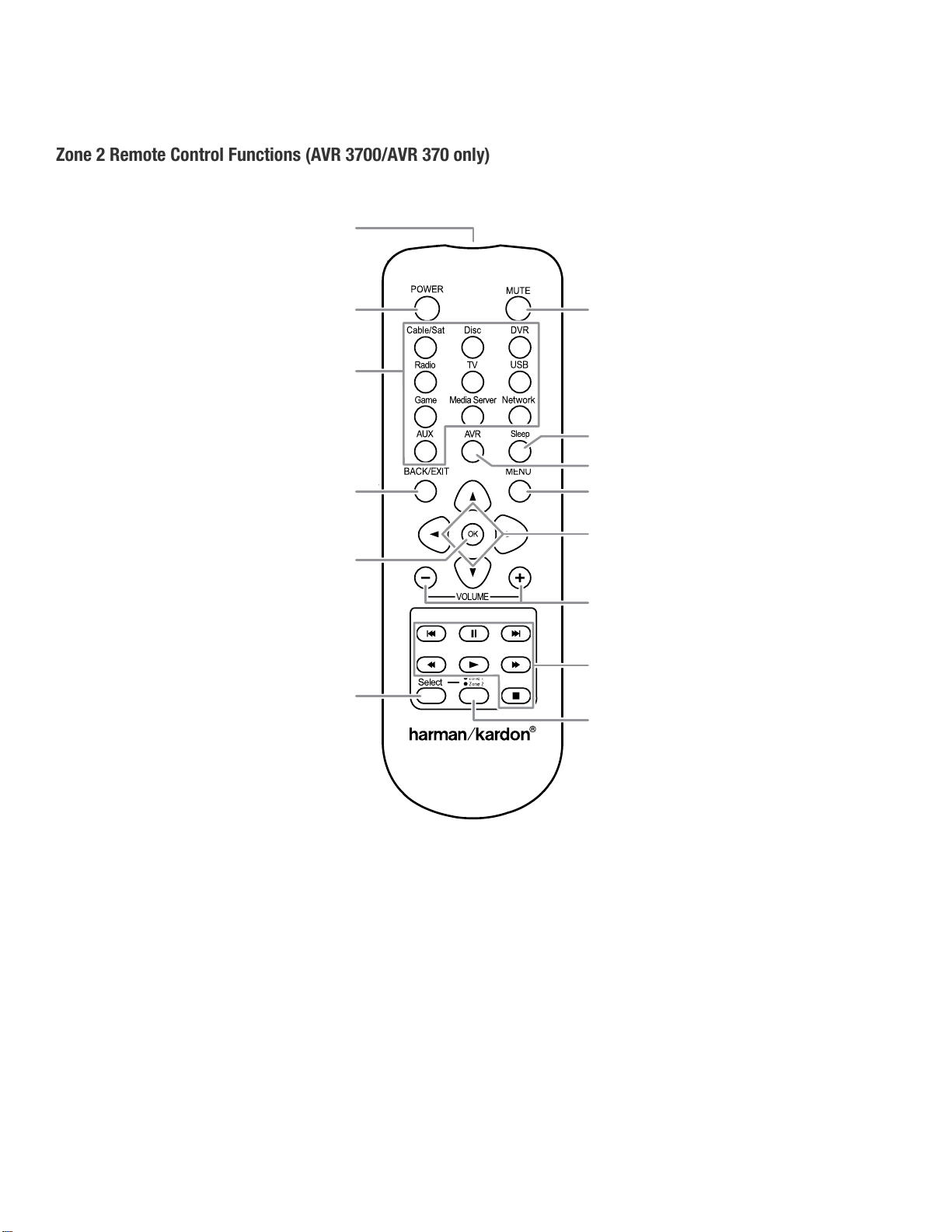
Zone 2 Remote Control Functions
(AVR 3700/AVR 370 only)
IR Transmitter
Lens
Power Off
Button
Source Selector
Buttons
Back/Exit
Button
OK Button
Zone Selector
Button
Mute Button
Sleep Button
AVR Button
Menu Button
Up/Down/Left/Right
Buttons
Volume Up/Down
Buttons
Transport Control
Buttons
Zone Indicator
10
Page 16

AVR
Zone 2 Remote Control Functions
(AVR 3700/AVR 370 only), continued
By installing an IR receiver in the remote zone of a multizone system and connecting it to
the AVR’s Zone 2 IR Input connector, you can use the Zone 2 remote to control the sound
in the remote zone from within the remote zone. You can use it to control the AVR’s power,
volume and mute functions or to select a source input for the remote zone, and to control
a Harman Kardon source device connected to one of the AVR’s Remote IR Out connectors.
See Connect IR Equipment, on page 22, for more information.
You can also use the Zone 2 remote in the main listening room to control the AVR and
Harman Kardon Blu-ray Disc
the Zone 1 control mode (the remote’s Zone Indicator light will turn green), its power,
volume and mute controls will affect only the main listening area. To restore operation
to the remote zone, press the remote’s Zone Selector button so that its Zone Indicator
light turns red.
IR Transmitter lens: As buttons are pressed on the remote, infrared codes are emitted
through this lens.
Power Off button: Press this button to turn the AVR off.
Mute button: Press to mute the AVR’s remote-zone speakers. To restore the sound, press
this button, adjust the volume or turn off the multizone system. Make sure to switch the
remote to Zone 2 mode so that only the remote zone will be affected.
Source Selector buttons: With the remote in Zone 2 mode, press one of these buttons
to select a source device for the remote zone. Pressing the button will also turn on the
multizone system and switch the remote to the selected source device’s control mode.
You may select a different external source device than that for the main room, but not
different tuner bands. If you select the same source as that for the main room, any
commands sent to the source device will affect both zones.
• The first press of the Radio button switches the AVR to the last-used tuner band (AM
or FM). Each successive press changes the band.
• The first press of the USB button switches the AVR to the last-used source (USB or
iPod). Each successive press cycles between the two sources.
• The first press of the Network button switches the AVR to the last-used source
(Network or vTuner). Each successive press cycles between the two sources.
Sleep button: Press this button to activate the sleep timer, which turns off the receiver
after a programmed period of time. Each press increases the time by 10 minutes, up to
90 minutes – ending with the “Sleep Off” message.
AVR button: Press this button to turn on the AVR and select the last-used source. This
button is also used to switch the remote control to AVR control mode.
Back/Exit button: Press this button to return to the previous menu or to exit the menu
system.
Menu button: This button is used within the tuner menus (including SIRIUS Radio) and
The Bridge IIIP control menu, and is also used to display the main menu on some source
devices. To display the AVR’s menu system, press the AVR button.
Up/Down/Left/Right buttons: These buttons are used to navigate the menu system and
to operate the tuner.
OK button: This button is used to select items from the menu system.
Volume Up/Down buttons: Press to raise or lower the volume level in the remote zone.
Transport Control buttons: These buttons are used to control source devices and The
Bridge IIIP.
Zone Selector button and Zone Indicator light: Each press of the Zone Selector button
determines whether the AVR commands will affect the main listening area (Zone 1) or
the remote zone (Zone 2). The Zone Indicator light will turn green when Zone 1 has been
selected, and red when Zone 2 has been selected. The Zone Indicator light will also light
up briefly when any button is pressed.
™
, DVD, CD or tape players. When the Zone 2 remote is in
Zone 2 Remote Control Functions
(AVR 3700/AVR 370 only)
ENGLISH
11
Page 17

AVR
Introduction to Home Theater
Introduction to Home Theater
This introductory section will help you to familiarize yourself with some basic concepts
unique to multichannel surround-sound receivers, which will make it easier for you to set
up and operate your AVR.
Typical Home Theater System
A home theater typically includes an audio/video receiver, which controls the system
and supplies amplification for the loudspeakers; a disc player; a source component for
television broadcasts (cable box, satellite dish receiver, HDTV tuner or antenna connected
to the TV); a TV or video display; and multiple loudspeakers.
Multichannel Audio
The main benefit of a home theater system is its ability to produce “surround sound.”
Surround sound uses multiple speakers and amplifier channels to immerse you in the
audio/video presentation for a dramatically increased sense of realism.
Your AVR may have up to seven main speakers connected directly to it, plus a subwoofer.
Each main speaker is powered by its own amplifier channel inside the AVR. A system
with more than two speakers is called a multichannel system. The different main speaker
types in a home theater system are:
• Front Left and Right: The front left and right speakers are used as in a two-channel
system. In many surround-sound modes, these speakers are secondary, while the
main action, especially dialogue, is reproduced by the center speaker.
• Center: When you are watching movies and television programs, the center speaker
reproduces most of the dialogue and other soundtrack information, anchoring it with
the picture. When you are listening to a musical program, the center speaker helps
to create a seamless front soundstage, creating a realistic “you-are-there” listening
experience.
• Surround Left and Right: The surround left and right speakers produce ambient
sounds that help create a realistic and immersive surround-sound environment.
They also help recreate directional sound effects such as aircraft flyovers.
• Surround Back Left and Right: Surround back channel speakers are used with
surround modes such as the Dolby Digital EX, Dolby Digital Plus, Dolby TrueHD, DTS-
®
ES
(Discrete and Matrix), DTS-HD™ High Resolution Audio, DTS-HD Master Audio™
and Logic 7® 7.1 modes that are designed for 7.1-channel systems.
• Front Height Left and Right: Your AVR includes Dolby Pro Logic IIz decoding, which
uses the AVR’s Assigned Amp channels as front height channels. The addition of
front height channels – an additional pair of speakers positioned above the front left
and right speakers – produces a surround-sound experience with added depth and
dimension by creating lifelike sound that comes at you from varying heights.
NOTE: You can set up your system to use either surround back speakers or front height
speakers; you cannot use both.
The surround back channel speakers are optional. If your system does not include
surround back left and right speakers, you can set up your AVR with a 5.1-channel
surround-sound system in the main listening area, and you can reassign the surround
back channel amplifiers to power loudspeakers located in another room in a multizone
system. (Alternately, you can reassign the surround back channel amplifiers to power
front height speakers for use with Dolby Pro Logic IIz. See Manual Speaker Setup, on
page 36, for more information.)
Many people expect the surround speakers to play as loudly as the front speakers.
Although you will calibrate all of the speakers in your system to sound equally loud at the
listening position, most artists use the surround speakers for ambient effects only, and
they create their programs to steer relatively little sound to these speakers.
• Subwoofer: A subwoofer is designed to play only the lowest frequencies (the deep
bass). It augments smaller, limited-range main speakers that are usually used for
the other channels. Many digital-format programs, such as movies recorded in
Dolby Digital, contain a low-frequency effects (LFE) channel that is directed to the
subwoofer. The LFE channel packs the punch of a rumbling train or airplane, or the
power of an explosion, adding realism and excitement to your home theater. Some
people use two subwoofers for additional power and for even distribution of the
sound.
Surround Modes
There are different theories as to the best way to present surround sound and to
distribute each audio channel’s sounds to the surround-sound system’s speakers.
A variety of algorithms have been developed in an effort to recreate the way we hear
sounds in the real world, resulting in a rich variety of options. Several companies
have developed different surround-sound technologies, all of which can be accurately
reproduced by your AVR:
• Dolby Laboratories: Dolby TrueHD, Dolby Digital Plus, Dolby Digital, Dolby Digital
EX, Dolby Pro Logic
• DTS: DTS-HD High Resolution Audio, DTS-HD Master Audio, DTS, DTS-ES (Discrete
and Matrix), DTS Neo:6
• HARMAN International: Logic 7
• Stereo Modes: Generic modes that expand upon conventional two-channel stereo,
including 5CH and 7CH Stereo.
Appendix Table A12, on page 50, contains detailed explanations of the different surroundsound options available on your AVR. Digital surround-sound modes, such as the Dolby
Digital and DTS modes, are available only on specially encoded programs, such as those
available via HDTV, DVD and Blu-ray Disc media and digital cable or satellite television.
Other surround modes may be used with digital and analog signals to create a different
surround presentation or to use a different number of speakers. Surround-mode selection
depends upon the number of speakers in your system, the program you are watching or
listening to, and your personal tastes.
®
IIx and IIz.
®
, DTS 96/24™.
®
, HARMAN virtual speaker, HARMAN headphone.
12
Page 18
AVR
Place Your Speakers
ENGLISH
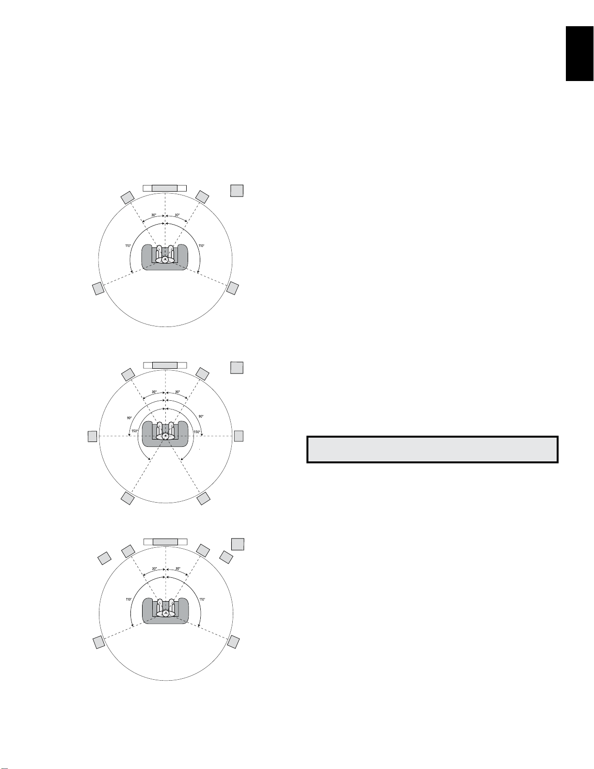
Place Your Speakers
Determine the locations for your system’s speakers according to their manufacturer’s
directions and the layout of your listening room. Use the illustrations below as a guide for
7.1-channel and 5.1-channel systems.
To create the most realistic surround-sound environment possible, you should place
your speakers in a circle with the listening position at its center. You should angle each
speaker so it directly faces the listening position. Use the diagrams below as a guide.
TV
C
FL
SL
Speaker Positioning for 5.1-Channel Systems
TV
C
FL
SUB
FR
SR
SUB
FR
SRSL
NOTE: In a 7.1-channel system, you must choose to use either surround back speakers
or front height speakers – you cannot use both simultaneously.
Placing the Left, Center and Right Speakers
Place the center speaker either on top of, below or mounted on the wall above or below
the TV or video display screen. Place the front left and right speakers along the circle,
about 30 degrees from the center speaker and angled toward the listener.
Place the front left, front right and center speakers at the same height, preferably at
about the same height as the listener’s ears. The center speaker should be no more than
2 feet (0.6m) above or below the left/right speakers. If you’re using only two speakers
with your AVR, place them in the front left and right positions.
Placing the Surround Speakers in a 5.1-Channel System
You should place the left and right surround speakers approximately 110 degrees from
the center speaker, slightly behind and angled toward the listener. Alternatively, place
them behind the listener, with each surround speaker facing the opposite-side front
speaker. You should place the surround speakers 2 feet – 6 feet (0.6m – 1.8m) higher
than the listener’s ears.
Placing the Surround Speakers in a 7.1-Channel System
In a 7.1-channel system, place the side surround speakers 90 degrees from the center
speaker, directly to either side of the listening position. Place the surround back left and
right speakers 150 degrees from the center speaker, directly facing the opposite-side
front speaker. You should place all the surround speakers 2 feet – 6 feet (0.6m – 1.8m)
higher than the listener’s ears.
Placing Front Height Speakers in a 7.1-Channel System
Your AVR includes Dolby Pro Logic IIz decoding, which uses the AVR’s Assigned Amp
channels as front height channels. The addition of front height channels – an additional
pair of speakers positioned above the front left and right speakers – produces a surroundsound experience with added depth and dimension by creating lifelike sound that comes
at you from varying heights.
We recommend placing front height speakers at least 3 feet (0.9m) higher than the front
left and front right speakers, and directly above or farther apart than the front left and
right speakers. The higher and further apart you place the front height speakers, the more
you should angle them down and in toward the listening position.
SBL
TV
C
FHL* FHR*
(Top: with Surround Back Speakers; Bottom: with Front Height Speakers)
FL
* FHL and FHR speakers should be at least
3 ft (0.9m) above the FL and FR speakers.
Speaker Positioning for 7.1-Channel Systems
SBR
SUB
FR
SRSL
NOTE: Your receiver will sound its best when the same model or brand of loudspeaker
is used for all positions.
Placing the Subwoofer
Because a room’s shape and volume can have a dramatic effect on a subwoofer’s
performance, it is best to experiment with placement so that you will find the location
that produces the best results in your particular listening room. With that in mind, these
rules will help you get started:
• Placing the subwoofer next to a wall generally will increase the amount of bass in
the room.
• Placing the subwoofer in a corner generally will maximize the amount of bass in
the room.
• In many rooms, placing the subwoofer along the same plane as the left and right
speakers can produce the best integration between the sound of the subwoofer and
that of the left and right speakers.
• In some rooms, the best performance could even result from placing the subwoofer
behind the listening position.
A good way to determine the best location for the subwoofer is by temporarily placing it in
the listening position and playing music with strong bass content. Move around to various
locations in the room while the system is playing (putting your ears where the subwoofer
would be placed), and listen until you find the location where the bass performance is
best. Place the subwoofer in that location.
13
Page 19
AVR
A. Tighten CapB. Insert Banana Connector
into Hole in Cap
Types of Home Theater System Connections
Types of Home Theater System Connections
There are different types of audio and video connections used to connect the AVR to your
speakers, your TV or video display, and your source devices. The Consumer Electronics
Association has established the CEA® color-coding standard.
Analog Audio Connection Color
Front Left/Right White/Red
Center Green
Surround Left/Right Blue/Gray
Surround Back/Front Height Left/Right Brown/Tan
Subwoofer Purple
Digital Audio Connection Color
Coaxial (input or output) Orange
Optical Input Black
Optical Record Output Gray
Analog Video Connection Color
Component Video Red/Green/Blue
Composite Video Yellow
Speaker Connections
Speaker cables carry an amplified signal from the AVR’s speaker terminals to each
loudspeaker. They contain two wire conductors, or leads, that are differentiated in some
way, such as with colors or stripes.
The differentiation helps you maintain proper polarity, without which your system’s lowfrequency performance can suffer. Each speaker is connected to the AVR’s speakeroutput terminals using two wires, one positive (+) and one negative (–). Always connect
the positive terminal on the speaker, which is usually colored red, to the positive terminal
on the receiver, which is colored as indicated in the Connection Color Guide Table, above.
The negative terminals on the speakers and the AVR are black.
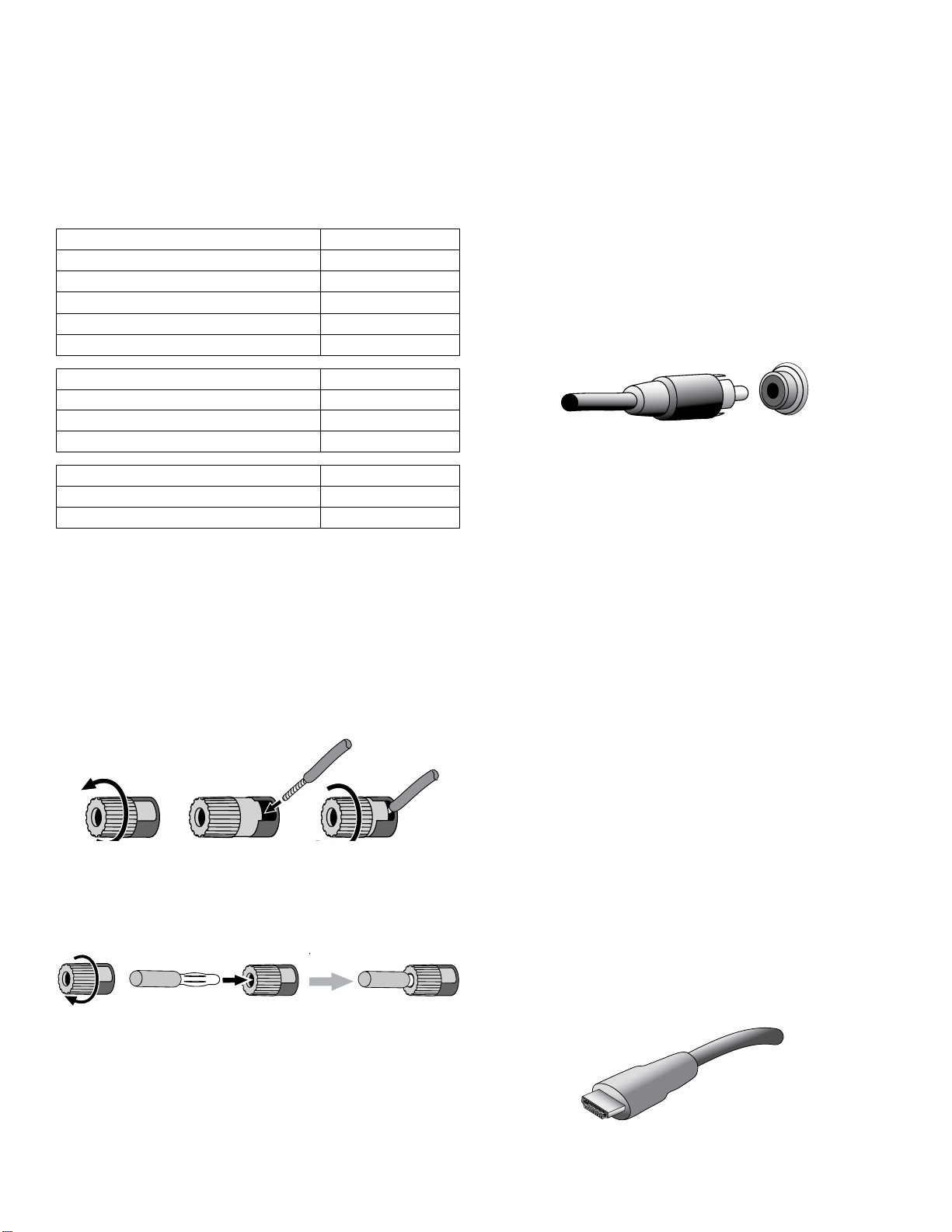
Your AVR uses binding-post speaker terminals that can accept bare-wire cables or
banana plugs. Bare-wire cables are installed as shown below:
1. Unscrew Cap 3. Tighten Cap2. Insert Bare Wire
Banana plugs are inserted into the hole in the middle of the terminal cap, as shown
below:
A. Tighten Cap
B. Insert Banana Connector into Hole in Cap
Always connect the colored (+) terminal on the AVR to the (+) terminal on the speaker
(usually red), and the black (–) terminal on the AVR to the (–) terminal on the speaker
(usually black).
IMPORTANT: Make sure the ( + ) and ( – ) bare wires do not touch each other or
the other terminal. Touching wires can cause a short circuit that can damage your
receiver or amplifier.
Subwoofer Connections
The subwoofer is a speaker dedicated to reproducing only the low (bass) frequencies,
which require more power. To obtain the best results, most speaker manufacturers offer
powered subwoofers that contain their own amplifiers. Use a single RCA audio cable to
make a line-level (non-amplified) connection from the AVR’s Subwoofer connector to a
corresponding input jack on the subwoofer.
Although the AVR’s purple subwoofer output looks similar to a full-range analog audio
jack, it is filtered so that only the low frequencies pass through it. Don’t connect this
output to any device other than a subwoofer.
Source Device Connections
Audio and video signals originate in source devices (components where a playback
signal originates) such as your Blu-ray Disc or DVD player, CD player, DVR (digital video
recorder) or other recorder, tape deck, game console, cable or satellite television tuner,
an iPod or iPhone (connected to the AVR’s USB port) or an MP3 player. The AVR’s FM/AM
tuner also counts as a source, even though no external connections are needed other
than the FM and AM antennas. Separate connections are required for the audio and video
portions of the source device’s signal, except for digital HDMI connections. The types of
connections you use will depend upon the capabilities of the source device and of your
TV or video display.
Digital Audio Connections – HDMI
There are two types of audio connections – digital and analog. Digital audio signals are
required for listening to sources encoded with digital surround modes, such as Dolby
Digital and DTS, or for uncompressed PCM digital audio. Your AVR has three types of
digital audio connections: HDMI, coaxial and optical. Do not use more than one type of
digital audio connection for each source device. However, it’s okay to make both analog
and digital audio connections to the same source.
Your AVR is equipped with seven rear-panel HDMI input connectors, and one HDMI
monitor output connector. (The AVRs also have a front-panel HDMI input connector.) HDMI
technology enables digital audio and video information to be carried using a single cable,
delivering the highest quality picture and sound. If your TV or video display device has an
HDMI input connector, make a single HDMI connection from each source device to the
AVR. Usually, a separate digital audio connection is not required.
The AVR’s HDMI output connection contains an Audio Return Channel (ARC) that carries
a digital audio signal from your TV or video display back to the AVR. It allows you to listen
to HDMI devices that are connected directly to your TV (such as an Internet connection)
without making an additional connection from the device to the AVR. The ARC signal
is active when the TV source is selected. See System Settings, on page 39, for more
information. (The AVR 3700 and AVR 370 have two HDMI output connections.)
The HDMI connector is shaped for easy plug-in (see illustration, below), and HDMI
cable runs are limited to about 10 feet (3m). If your video display has a DVI input and is
HDCP-compliant, use an HDMI-to-DVI adapter (not included), and make a separate audio
connection.
14
Page 20
AVR
Types of Home Theater System Connections
ENGLISH
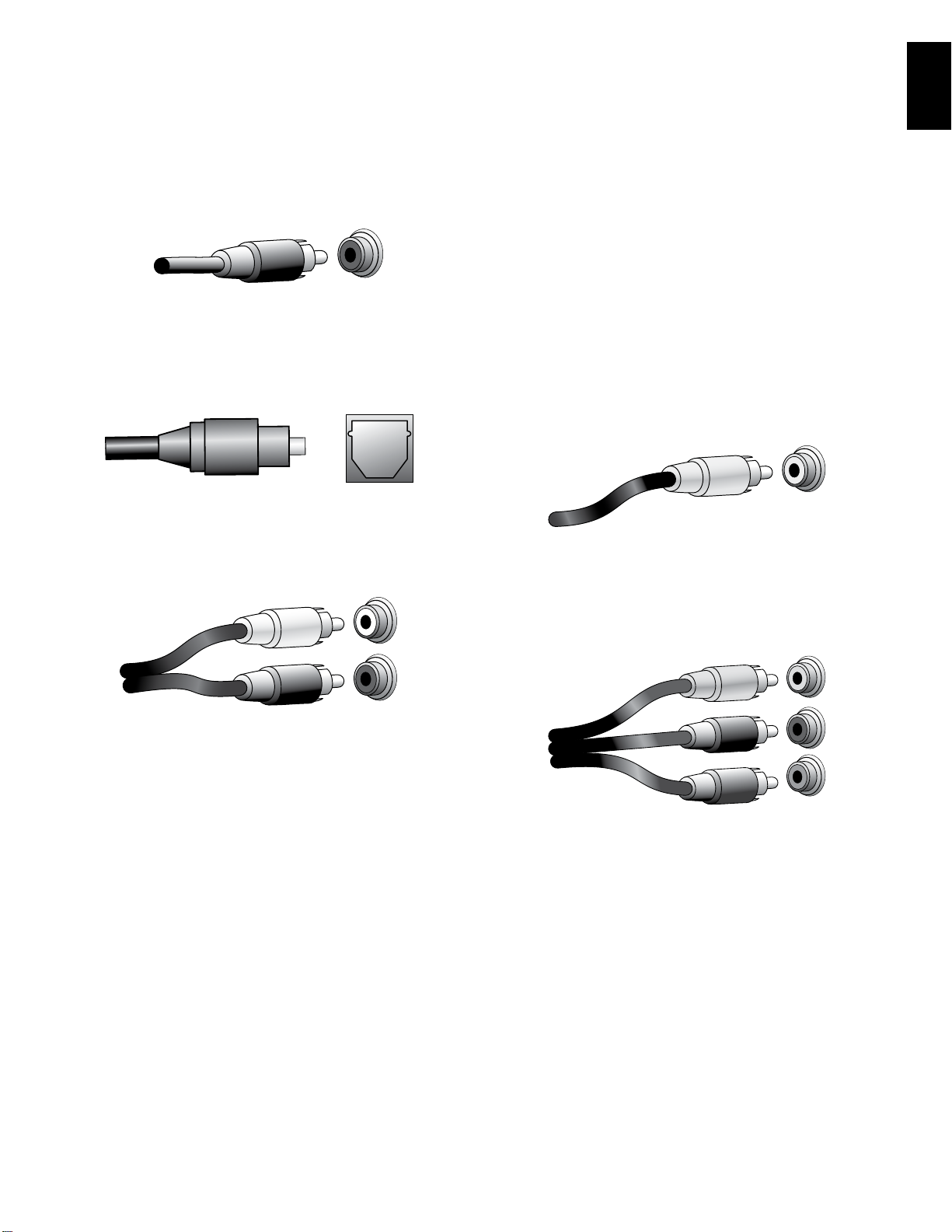
Digital Audio Connections – Coaxial
Coaxial digital audio jacks are usually color-coded in orange. Although they look like
standard RCA-type analog jacks, you should not connect coaxial digital audio outputs to
analog inputs or vice versa.
Digital Audio Connections – Optical
Optical digital audio connectors are normally covered by a shutter to protect them from
dust. The shutter opens as the cable is inserted. Optical input connectors are color-coded
using a black shutter, while optical outputs use a gray shutter.
Analog Audio Connections
Two-channel analog connections require a stereo audio cable, with one connector for
the left channel (white) and one for the right channel (red). These two connectors are
attached to each other.
Video Connections
Many source devices output both audio and video signals (e.g., Blu-ray Disc, DVD
player, cable television box, HDTV tuner, satellite box, VCR, DVR). In addition to an audio
connection as described above, make a video connection for each of these source
devices. Make only one type of video connection for each device.
Digital Video Connections
If you have already connected a source device to one of the AVR’s HDMI input connectors,
you have automatically made a video connection for that device, since the HDMI cable
carries both digital audio and digital video signals.
Analog Video Connections – Composite Video
Your AVR uses two types of analog video connections: composite video and component
video.
Composite video is the basic connection most commonly available. Both the chrominance
(color) and luminance (intensity) components of the video signal are transmitted using a
single cable. The jack is usually color-coded yellow and looks like an analog audio jack.
Do not connect a composite video jack to an analog audio or coaxial digital audio jack,
or vice versa.
Analog Video Connections – Component Video
Component video separates the video signal into three components – one luminance
(“Y”) and two sub-sampled color signals (“Pb” and “Pr”) – that are transmitted using
three separate cables that are color-coded green (Y), blue (Pb) and red (Pr). Component
video cables that join three separate green, blue and red connectors into a single cable
are sold separately.
For source devices that have both digital and analog audio outputs, you may make both
connections. If you are going to be setting up a multizone system, remember that Zone
2 is an audio-only zone (the AVR does not have a Zone 2 video output). Therefore, make
analog connections for any audio source devices (such as a CD changer) that you will
want available for listening in Zone 2 at all times.
The analog connections also feed the analog record outputs. You may record materials
from Blu-ray Disc recordings, DVDs or other copy-protected sources using only analog
connections. Remember to comply with all copyright laws if you choose to make a copy
for your own personal use.
If your TV or video display has an HDMI connection, we recommend it as the best quality
connection. Your AVR converts composite and component analog video input signals to
the HDMI format, upscaling them to high-definition 1080p resolution.
15
Page 21
AVR
Types of Home Theater System Connections
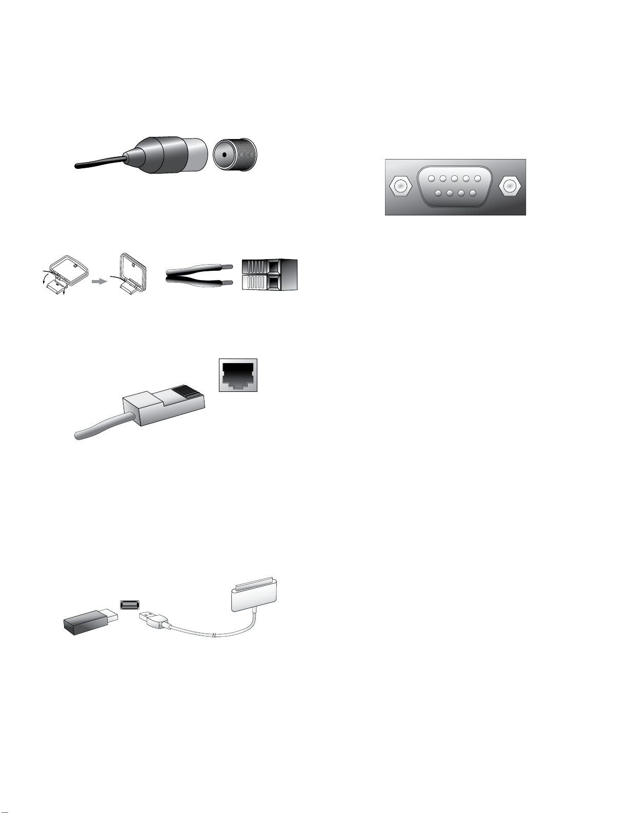
Radio Connections
Your AVR uses separate terminals for the included FM and AM antennas. The FM antenna
uses a 75-ohm F-connector.
The AM antenna connector uses spring-clip terminals. After assembling the antenna as
shown below, press the levers to open the connectors, insert the bare wires into the
openings, and release the levers to secure the wires. The antenna wires are not polarized,
so you can insert either wire into either connector.
Network Connector
The AVR’s Network connector allows you to enjoy Internet radio or content from other
DLNA-compatible devices that are connected to the same network. Use a Cat. 5 or
Cat. 5E Ethernet cable to connect the AVR’s RJ-45 connector to your home network.
RS-232 Connector
Your AVR’s RS-232 serial port may be connected to an external control system to allow
it to transmit control commands to the AVR. The port is bidirectional so that the AVR
can transmit status updates to the control device. Connecting and using the RS-232
port requires considerable technical knowledge and is best left to a professional custom
installer.
USB Port
The AVR can play audio files from an Apple iOS® device connected to the USB port,
and allows you to control the iOS device via the AVR remote control. The AVR can also
play MP3 and WMA audio files from a USB device inserted into the USB port. Insert the
connector or device into the USB port oriented so it fits all the way into the port. You may
insert or remove the connector or device at any time – there is no installation or ejection
procedure.
The USB port on your AVR is also used to perform firmware upgrades. If an upgrade for
the AVR’s operating system is released in the future, you will be able to download it to the
AVR using this port. Complete instructions will be provided at that time.
IMPORTANT: Do not connect a PC or other USB host/controller to the AVR’s USB
port, or you may damage both the AVR and the other device.
16
Page 22
AVR
Making Connections
ENGLISH
Making Connections
CAUTION: Before making any connections to the audio/video receiver, ensure
that the AVR’s AC cord is unplugged from the receiver and the AC outlet.
Making connections with the receiver plugged in and turned on could damage
the speakers.
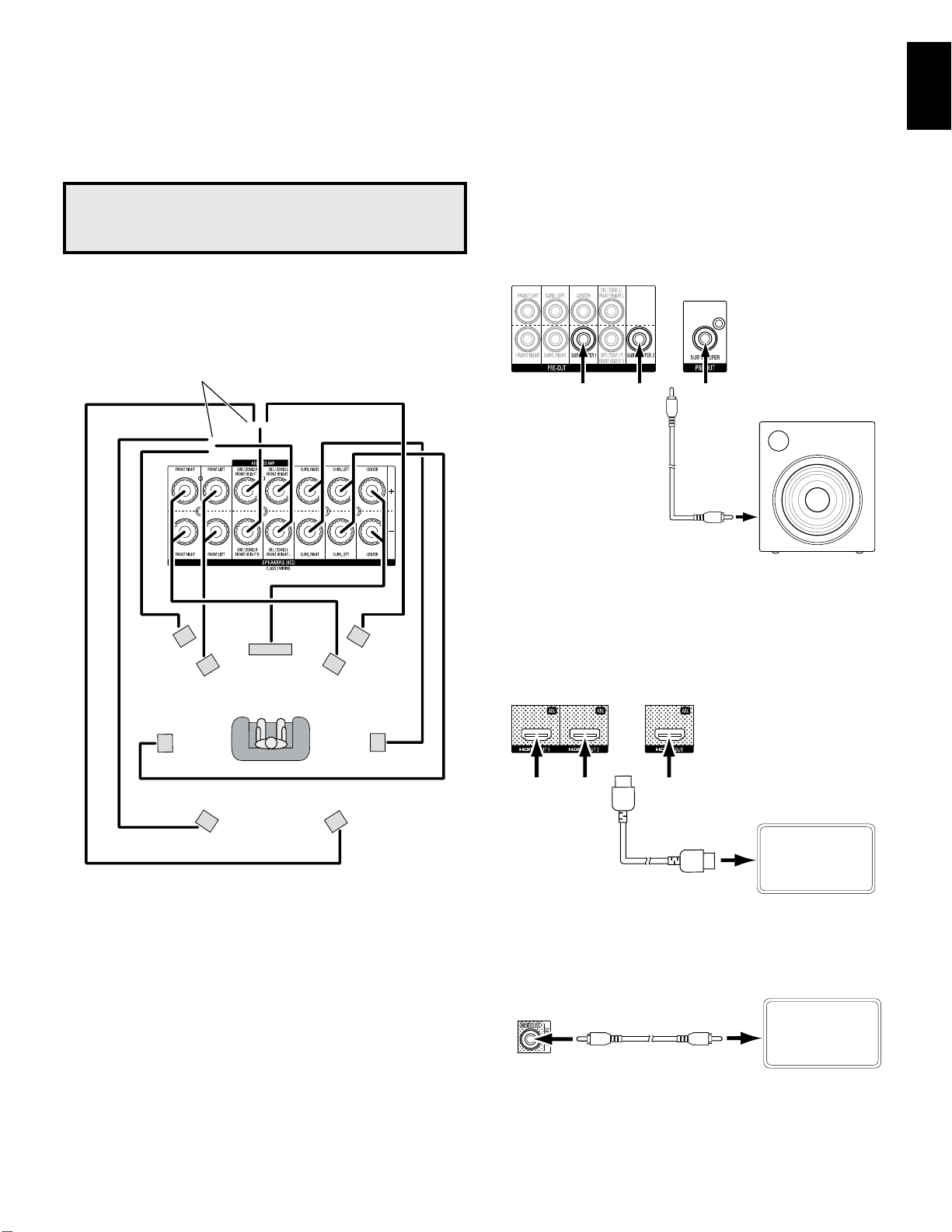
Connect Your Speakers
After you have placed your loudspeakers in the room as explained in Place Your Speakers,
on page 13, connect each speaker to its color-coded terminal on the AVR as explained
in Speaker Connections, on page 14. Connect the speakers as shown in the illustration.
Connect Surround Back L/R Speakers
-OR- Front Height L/R Speakers Here
FHL
C
FL
FHR
FR
Connect Your Subwoofer
Use a single RCA audio cable to connect the AVR’s Subwoofer connector to your subwoofer
as explained in Subwoofer Connections, on page 14. NOTE: The AVR 3700 and AVR 370
provide connections for two subwoofers. See Manual Speaker Setup: Number of Speakers,
on page XX, for information about activating the two subwoofer outputs. Consult your
subwoofer’s user manual for specific information about making connections to it.
AVR 3700/
AVR 370/AVR 370C
Use either
connector
AVR 2700/
AVR 270/
AVR 270C
Powered
Subwoofer
Single
RCA Audio
Cable
(not
supplied)
Connect Your TV or Video Display
If your TV has an HDMI connector: Use an HDMI cable (not included) to connect it to the
AVR’s HDMI Monitor Out connector. The AVR 3700 and AVR 370 provide HDMI connections
for two TVs. You do not need to make any other connections to your TV from the receiver
or from any of your video source components.
AVR 2700/
AVR 3700/
AVR 370/AVR 370C
AVR 270/
AVR 270C
SL
SBL
NOTE: If you installed front height speakers, connect them as shown for the SBL and
SBR speakers.
SR
SBR
Use either
connector
HDMI Cable
(not supplied)
If your TV does not have an HDMI connector: Use a composite video cable (not
included) to connect the AVR’s Composite Monitor Out connector to your TV’s composite
video connector.
AVR
Composite
Monitor Out
Connector
Composite Video Cable
(not supplied)
NOTE: The HDMI connection to your TV is preferred. If you use the composite video
connection to your TV, you will not be able to view the AVR’s on-screen menus.
TV
TV
17
Page 23
AVR
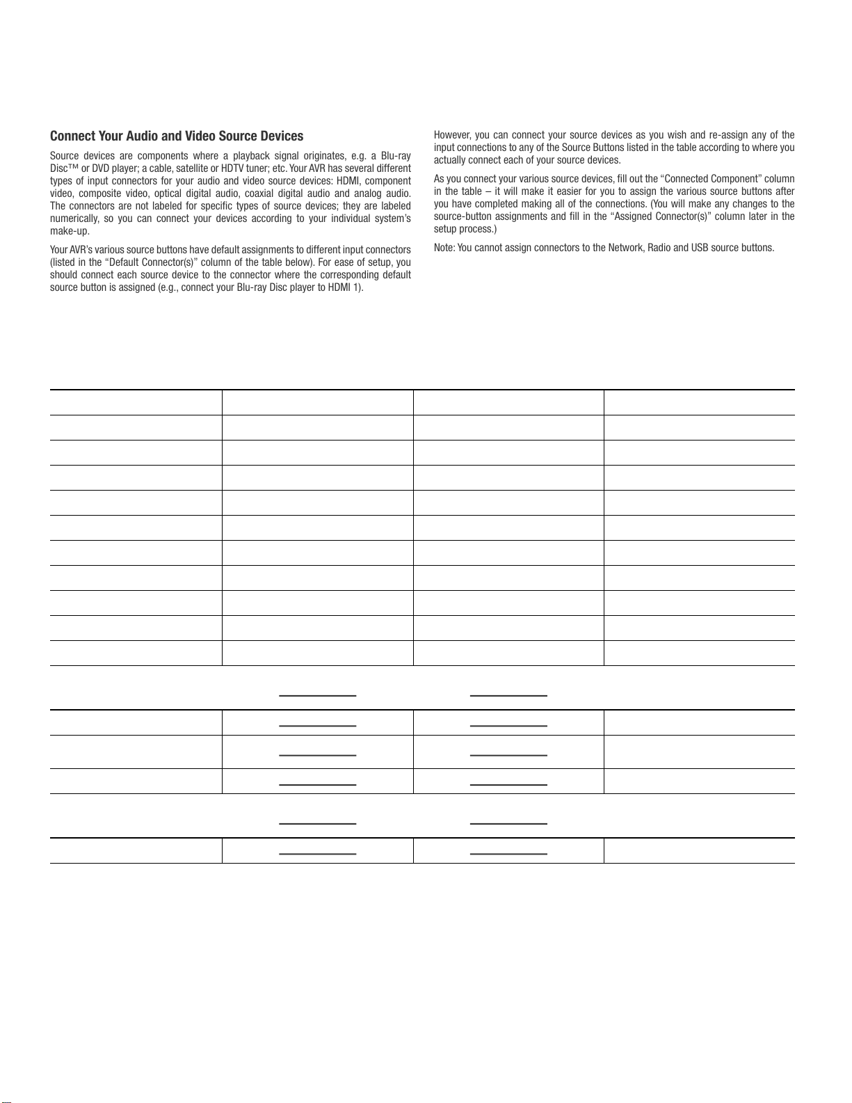
Connect Your Audio and Video Source Devices
Source devices are components where a playback signal originates, e.g. a Blu-ray
Disc™ or DVD player; a cable, satellite or HDTV tuner; etc. Your AVR has several different
types of input connectors for your audio and video source devices: HDMI, component
video, composite video, optical digital audio, coaxial digital audio and analog audio.
The connectors are not labeled for specific types of source devices; they are labeled
numerically, so you can connect your devices according to your individual system’s
make-up.
Your AVR’s various source buttons have default assignments to different input connectors
(listed in the “Default Connector(s)” column of the table below). For ease of setup, you
should connect each source device to the connector where the corresponding default
source button is assigned (e.g., connect your Blu-ray Disc player to HDMI 1).
However, you can connect your source devices as you wish and re-assign any of the
input connections to any of the Source Buttons listed in the table according to where you
actually connect each of your source devices.
As you connect your various source devices, fill out the “Connected Component” column
in the table – it will make it easier for you to assign the various source buttons after
you have completed making all of the connections. (You will make any changes to the
source-button assignments and fill in the “Assigned Connector(s)” column later in the
setup process.)
Note: You cannot assign connectors to the Network, Radio and USB source buttons.
Source Button Default Connector(s) Assigned Connector(s) Connected Device
Cable/Sat HDMI 2
Making Connections
Disc HDMI 1
Game HDMI 3
Media Server HDMI 4
DVR HDMI 5
TV None/Optical Digital Audio 1
Aux HDMI Front
A (red) HDMI 6
B (green) HDMI 7
C (yellow) Composite Video 1/Analog Audio 1
D (blue) Composite Video 2/Analog Audio 2
Monitor Output Connector Connected Device
HDMI Out 1
HDMI Out 2
(AVR 3700/AVR 370 only)
Composite Video Monitor Out
Record Output Connector Connected Device
Analog Audio Rec Out
Source Buttons and Assigned Connectors
18
Page 24
AVR
Making Connections
ENGLISH
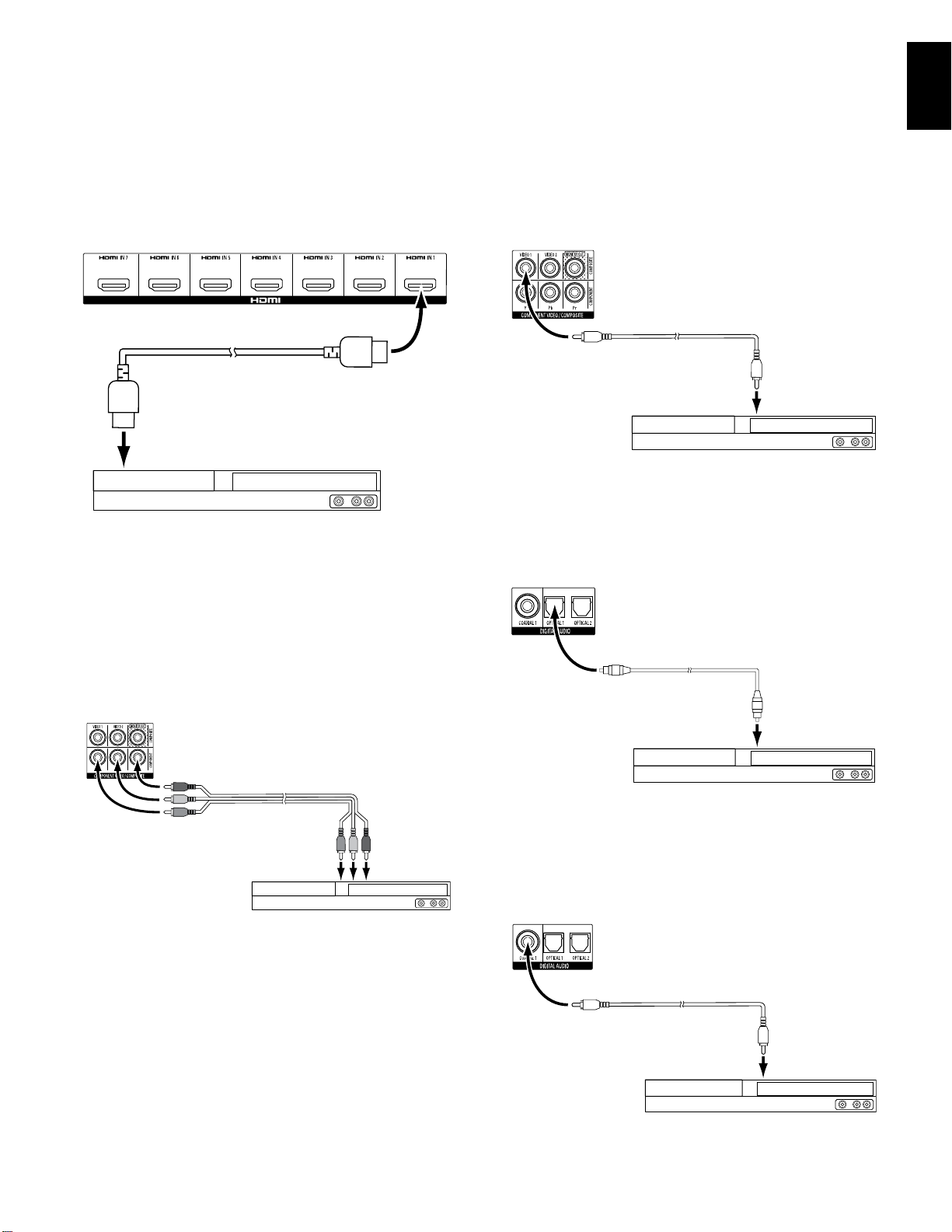
Connect Your HDMI Devices
If any of your source devices have HDMI connectors, using them will provide the best
possible video and audio performance quality. Since the HDMI cable carries both digital
video and digital audio signals, you do not have to make any additional audio connections
for devices you connect via an HDMI cable.
AVR HDMI Connectors
HDMI Cable
(not supplied)
To HDMI
Output
HDMI-Equipped Source Device
NOTE: If you have HDMI devices (such as an Internet connection) already connected
directly to your TV, you can feed their sound to the AVR via the HDMI Out connector’s
Audio Return Channel, and they will not require additional connections to the AVR.
Connect Your Composite Video Devices
Use composite video connectors for video source devices that don’t have HDMI or
component video connectors. You will also need to make an audio connection from the
source device to the receiver.
AVR Analog
Video Connectors
Composite Video
Cable (not supplied)
To Composite
Video Output
Composite Video-Equipped Source Device
Connect Your Optical Digital Audio Devices
If your non-HDMI source devices have optical digital outputs, connect them to the AVR’s
optical digital audio connectors. NOTE: Make only one type of digital connection (HDMI,
optical or coaxial) from each device.
AVR Digital
Audio Connectors
Connect Your Component Video Devices
If any of your video source devices have component video connectors (and do not have
HDMI connectors), using the component video connectors will provide superior video
performance. You will also need to make an audio connection from the device to the
receiver.
AVR Analog
Video Connectors
Component Video
Cable (not supplied)
To Component
Video Outputs
Component Video-Equipped Source Device
Optical Digital Audio
Cable (not supplied)
To Optical Digital
Audio Output
Optical-Equipped Source Device
Connect Your Coaxial Digital Audio Devices
If your non-HDMI source device has a coaxial digital output, connect it to the AVR’s
coaxial digital audio connector. NOTE: Make only one type of digital connection (HDMI,
optical or coaxial) from each device.
AVR Digital
Audio Connectors
Coaxial Digital Audio
Cable (not supplied)
To Coaxial Digital
Audio Output
Coaxial-Equipped Source Device
19
Page 25
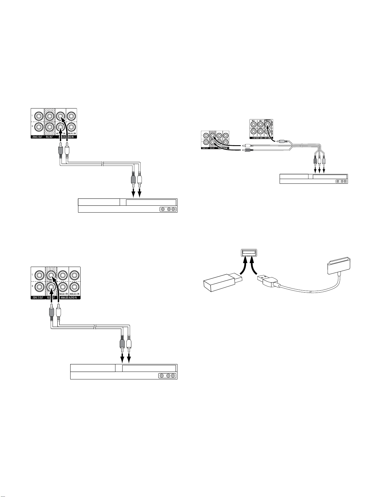
AVR
Making Connections
Connect Your Analog Audio Devices
Use the AVR’s analog audio connectors for source devices that don’t have HDMI or digital
audio connectors. NOTE: If you’re installing a multizone system, make analog audio
connections for any source devices you want to be able to listen to in Zone 2. Only analog
sources are available in Zone 2.
Receiver Analog
Audio Connectors
Stereo Audio Cable
(not supplied)
To Stereo Analog
Audio Output
Analog Source Device
Connect Your Audio Recorders
Connect an analog audio recorder’s inputs to the AVR’s analog audio Rec Out connectors.
You can record any analog audio input signal.
AVR Analog Audio
Recorder Connectors
Connect Your Video Recorder
Connect an analog video recorder’s video input connector to the AVR’s Composite Monitor
Out connector. You can record any composite video signal. To record the audio from
the source device, connect the AVR’s Analog Rec Out connectors to the analog video
recorder’s audio inputs. NOTE: If you have connected the AVR’s Composite Monitor Out
video connector to your TV you cannot connect a VCR to the AVR for recording.
AVR Analog
Video Recorder
AVR Analog
Audio Recorder
Connectors
Connectors
Analog Audio/Video
Cable (not supplied)
Analog Video Recording Device
To Analog
Audio/Video
Record Inputs
USB and iOS Devices
Use the AVR’s front-panel USB port to connect an iPod, iPhone or iPad using an Apple
cable (not supplied) or to directly connect a USB memory stick. You can play audio files
from the device or memory stick and use the AVR’s remote to control playback.
AVR
Front-Panel
USB Port
USB
Memory
Stick
Apple Cable
(not supplied)
Stereo Audio Cable
(not supplied)
To Stereo Analog
Record Inputs
Analog Recording Device
20
Page 26
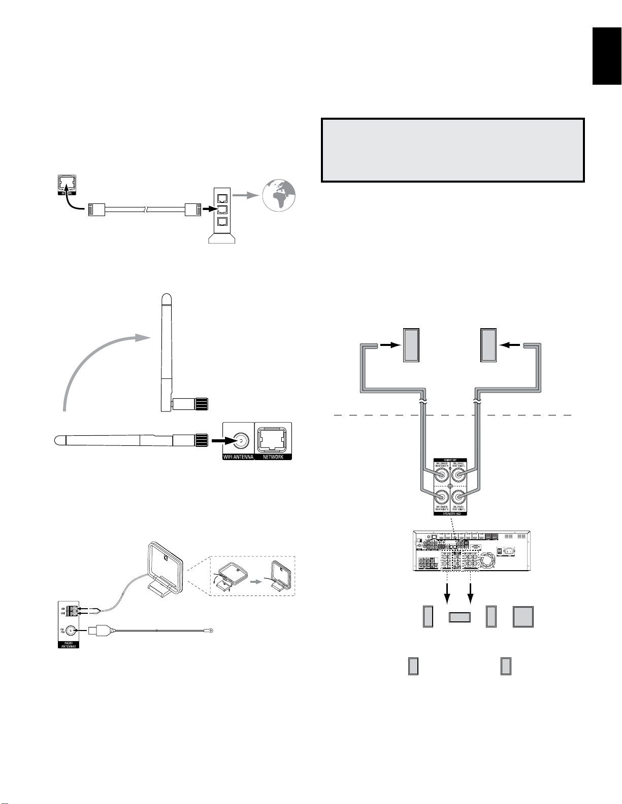
AVR
Making Connections
ENGLISH
Connect to Your Home Network
Use a Cat. 5 or Cat. 5E cable (not supplied) to connect the AVR’s Network connector to
your home network to enjoy Internet radio and content from DLNA-compatible devices
that are connected to the network.
AVR
Network
Connector
Cat. 5/5E Ethernet Cable
(not supplied)
AVR 3700/AVR 370 only:
If your home network is Wi-Fi®, attach the supplied Wi-Fi antenna to the AVR. You do not
need to make a wired network connection.
Network
Modem
To Home
Network
and Internet
Install a Multizone System
IMPORTANT SAFETY NOTE: Installing a multizone system typically requires
running cables inside walls. Always comply with the appropriate safety codes
when installing concealed wiring, particularly all applicable building codes.
Failure to do so may present a safety hazard. If you have any doubt about
your ability to work with electrical wiring, hire a licensed electrician or custom
installer to install the multizone system.
NOTE: Only the following analog audio sources are available to Zone 2: the internal radio,
an iPod/iPhone device or a USB memory device inserted in the AVR’s USB port and up
to two source devices connected to the rear-panel Analog Audio In 1 and 2 connectors.
Your AVR offers two different methods of distributing audio to other areas in your home.
Each requires different connections:
A. Connect the Zone 2 speakers directly to the Assigned Amp Speaker Output
connectors. Assign the Assigned Amp channels to power the Zone 2 speakers (see
Manual Speaker Setup, on page 36). This method allows you to power a single pair of
speakers for Zone 2.
This method offers the benefit of reduced cost and complexity, but your home theater
system will be limited to 5.1 channels – the AVR will automatically downmix the playback
of programs recorded in 6.1 or 7.1 channels to 5.1 channels.
Zone 2
Speakers
Connect the Radio Antennas
• Connect the supplied FM antenna to the AVR’s FM 75Ω antenna connector. For the
best reception, extend the FM antenna as far as possible.
• Bend and fold the base of the supplied AM antenna as shown and connect the
antenna wires to the AVR’s AM and Gnd connectors. (You can connect either wire to
either connector.) Rotate the antenna as necessary to minimize background noise.
AM Antenna
(supplied)
AVR
Antenna
Connectors
Bend and fold base
FM Antenna (supplied)
Speaker Wire
(not supplied)
Assigned
Amp
Speaker
Connectors
AVR
FL
5.1-Channel
Home Theater
Speaker System
SL SR
C
Speaker Wire
(not supplied)
FR LFE
Zone 2
Main Room
21
Page 27
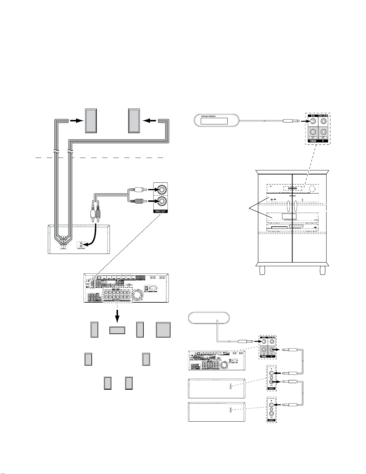
AVR
Making Connections
B. Connect an external amplifier to the AVR’s Zone 2 Out connectors. This method
offers the benefit of retaining a 7.1-channel home theater in the main room simultaneously
with multizone operation, although it does require an additional amplifier for Zone 2.
We recommend that you place the Zone 2 amplifier in the same room as the AVR so that
you can use a short length of stereo audio cable along with a long run of speaker wire to
the remote room. A long run of stereo audio cable would increase the chance of signal
degradation. Depending on your Zone 2 amplifier you can distribute the audio signal to a
single pair of speakers or to several pairs placed in different rooms.
Zone 2
Speakers
Zone 2
Speaker Wire
(not supplied)
Speaker Wire
(not supplied)
Stereo Audio Cable
(not supplied)
Main Room
Connect IR Equipment
The AVR is equipped with Remote IR Input and Output connectors and a Zone 2 IR Input
connector that let you remotely control the AVR in a variety of situations:
• When you place the AVR inside a cabinet or facing away from the listener, connect
an external IR receiver, such as the optional Harman Kardon HE 1000, to the AVR’s
IR In jack.
External IR
Receiver
AVR and Source Devices
Installed Inside of Cabinet
AVR
IR In Jack
Zone 2 Amplifier
(not supplied)
AVR
SL
FL
C
7.1-Channel
Home Theater
Speaker System
SBL SBR
FR LFE
SR
• If any source devices are equipped with a compatible IR input, use a 1/8-inch
(3.5mm) mini-plug interconnect cable (not included) to connect the AVR’s IR Out jack
to the source device’s IR input.
External IR Receiver
AVR
Mono 1/8-inch
(3.5mm) Mini-Plug
Interconnect
(not supplied)
Source Devices w/Remote In/Out Jacks
Mono 1/8-inch
(3.5mm) Mini-Plug
Interconnect
(not supplied)
22
Page 28
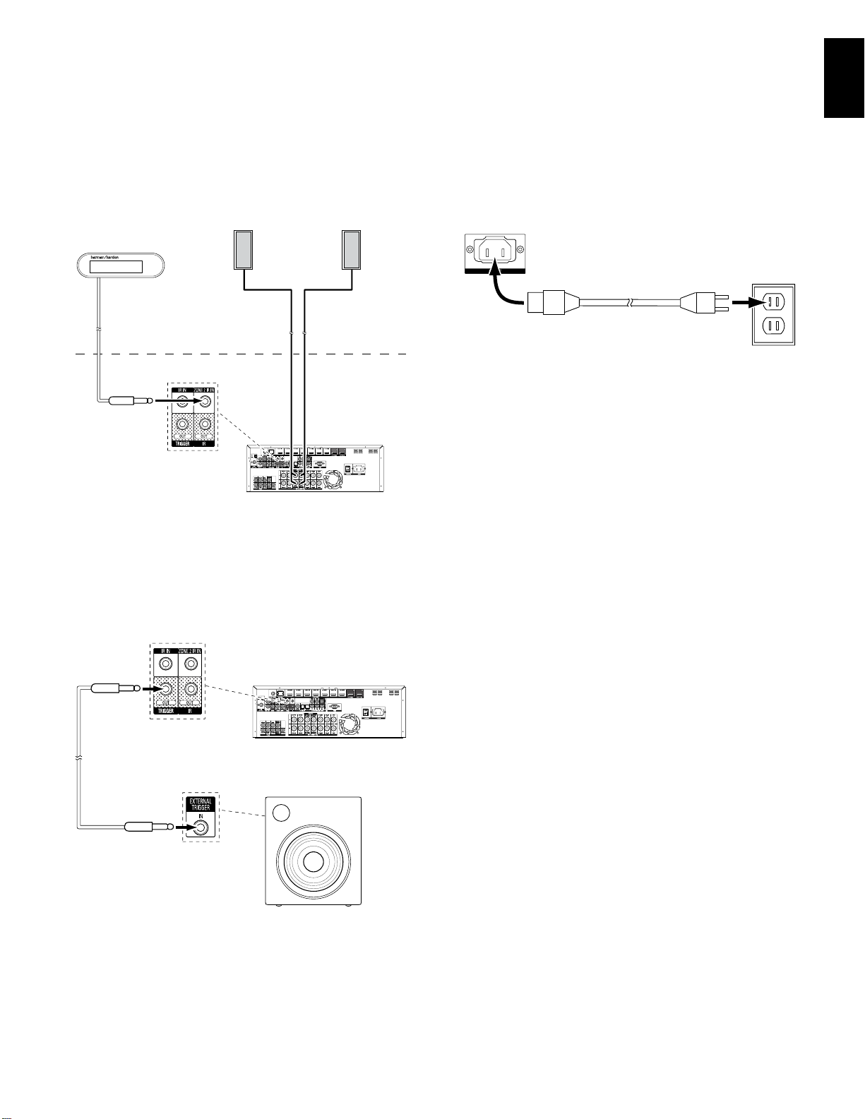
AVR
Making Connections,
ENGLISH
To control more than one source device through the AVR’s IR Remote Out connector,
connect all sources in “daisy chain” fashion, connecting each device’s IR output to the
next device’s IR input, starting with the AVR.
• If you install a multizone system, connect an IR control device to the Zone 2 IR In
connector for remote-room control of the multizone system, source devices and
volume in the remote zone.
External IR Receiver
If a source device is shared with the main listening area, any control commands issued
to that source will also affect the main room.
Zone 2 Speakers
Zone 2
Main Room
AVR
Connect to AC Power
Connect the supplied AC power cord to the AVR’s AC Input connector and then to a
working AC power outlet.
AVR
AC Input
Connector
AC Power
Outlet
Power Cord (supplied)
Connect the Trigger Output
If your system has equipment that can be controlled by a DC trigger signal, connect it to
the AVR’s Trigger Out connector with a mono 1/8-inch (3.5mm) mini-plug interconnect
cable. The AVR will supply a 12V DC (100mA) trigger signal at this connection whenever
it is powered on.
AVR
Mono 1/8-inch
(3.5mm) Mini-Plug
Interconnect
(not supplied)
Device with
Trigger In Connector
23
Page 29
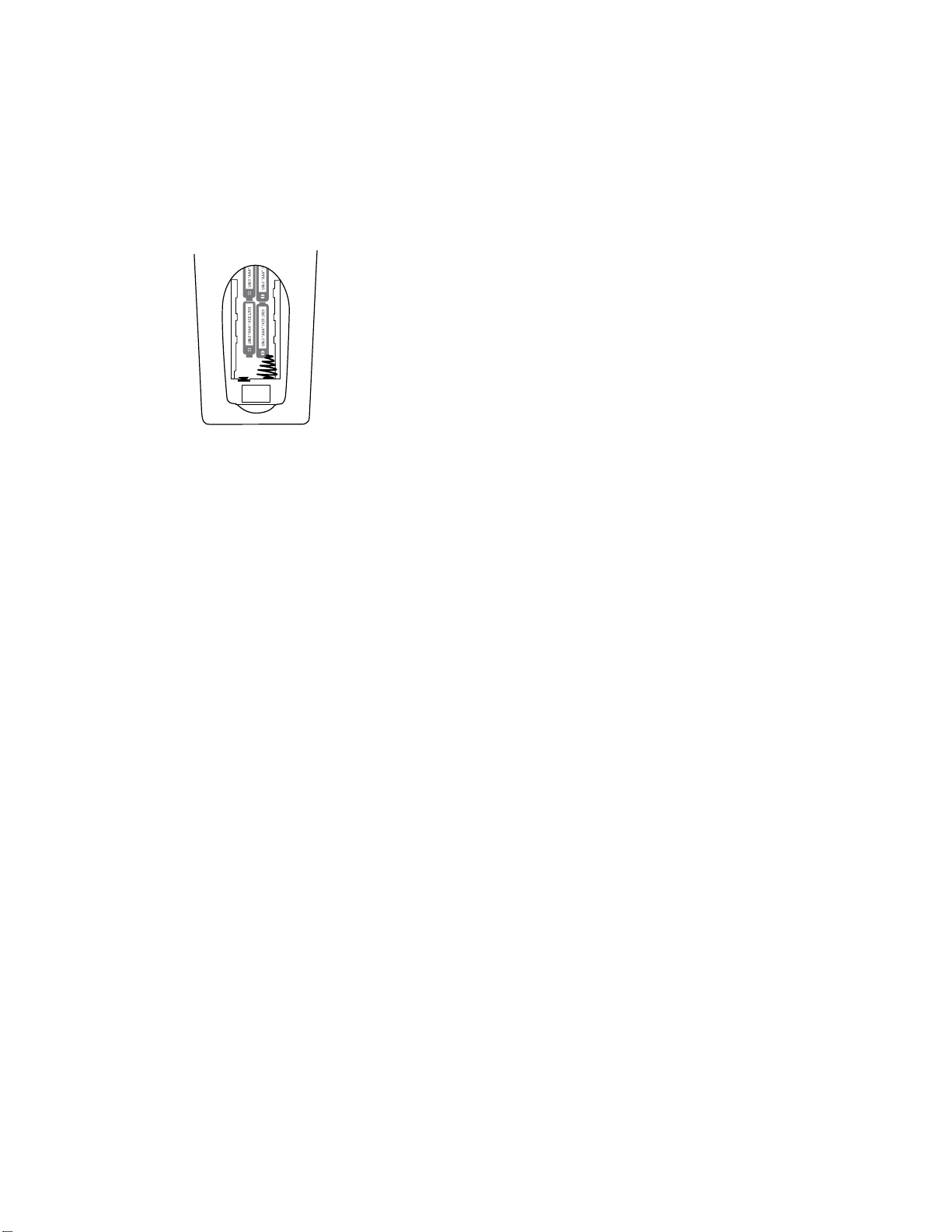
AVR
Set Up the Remote Control
Set Up the Remote Control
Install the Batteries in the Remote Control
Remove the remote control’s battery cover, insert the four supplied AAA batteries as
shown in the illustration, and replace the battery cover.
NOTE: Remove the protective plastic from the AVR’s front panel so it doesn’t reduce the
remote control’s effectiveness.
Program the Remote to Control Your Source Devices and TV
You can program your AVR remote to control many brands and models of audio/video
source devices and TVs. The remote is also ready to operate your iPod or iPhone when
the iPod/iPhone is docked in a connected The Bridge IIIP (not included).
Each of the remote’s Source Selector buttons has been preprogrammed to control certain
types of source devices:
Cable/Sat: Controls cable TV and satellite TV tuner boxes
Disc: Controls Blu-ray Disc and DVD players
Radio:
Controls the AVR’s built-in FM/AM tuner
TV:
Controls TVs and video displays
USB:
Browses compatible media on an Apple iOS device that is connected to, or a USB
device that is inserted in the AVR’s USB port Note: Does not require programming.
DVR:
Controls TiVo® recorders
Game:
Controls video-game consoles
Media Server:
Network:
home network and on vTuner (Internet Radio). Note: Does not require programming.
AUX:
Although the Source Selector buttons are preprogrammed for the device types listed
above, you can reassign a Source Selector button to a different device type. See
Reassigning a Source Selector Button for a Different Device Type, on page 24.
Once you have programmed the remote, you can switch the remote’s control mode to
access the functions for a particular device by pressing the remote’s Source Selector
button for that device.
Follow these steps to program the Source Selector buttons for your source devices:
1. Turn on the source device you want to program the remote to control.
2. Look up the code numbers for the device in Tables A14 – A24 in the Appendix. Write all
the applicable code numbers in a convenient place.
3. Press the Source Selector button for the device and hold it as it glows red, goes dark
and glows red again. Then release it. The remote is now in the Programming mode.
NOTE:
The remote will remain in the Programming mode for 20 seconds. If you do not
complete Step 4 within 20 seconds, the remote will exit the Programming mode, and you
will need to repeat Step 3.
Controls media servers
Browses compatible media on DLNA-compatible devices connected to your
Controls HDTV tuner boxes, CD players, VCRs and PVDs.
4. Aim the remote at the source device and use the remote’s Number buttons to enter a
code number from Step 1, above.
a) If the device turns off, press the Source Selector button again to save the code. The
Source Selector button will flash, and the remote will exit the Programming mode.
b) If the device does not turn off, enter another code number.
c) If you run out of code numbers for a device, you can search through all of the codes
in the remote’s library for dervices of its type by pressing the remote’s Up button
repeatedly until the device turns off. When it does, press the Source Selector button
to save the code.
5. Check that other functions control the device correctly. Sometimes manufacturers use
the same Power code for several models, while other function codes vary. Repeat this
process until you’ve programmed a satisfactory code set that operates most of the
device’s functions.
6. If you searched through the remote’s code library to find the code, you can find out
which code number you have programmed by pressing and holding the Source Selector
button to re-enter the Programming Mode. Then press the remote’s OK Button, and the
Source Selector button will flash in the code sequence. One flash represents “1,” two
flashes for “2,” and so forth. A series of quick flashes represents “0.” Record the code
number programmed for each device in Table A9 in the Appendix.
Repeat Steps 3 – 6 for each source device you want to control with the AVR remote.
Reassigning a Source Selector Button for a Different Device Type
You can reassign a Source Button to control a different device type (for example, you can
program the Media Server button to control a DVD player).
1. Turn on the source device you want the remote to control.
2. Look up the code numbers for the device in Tables A14 – A24 in the Appendix. Write all
the applicable code numbers in a convenient place.
3. Press the Source Selector button you want to override and hold it for three seconds
as it glows red, goes dark and glows red again. Then release it. The remote is now in
the Programming mode.
4. Press the Source Selector button that corresponds to the source device’s type (i.e.,
for a DVD player, press the Blu-ray button). The Source Selector button you pressed in
Step 3 will flash once.
5. Aim the remote at the source device and use the remote’s Number buttons to enter a
code number from Step 2, above.
a) If the device turns off, press the Source Selector button from Step 3 again to
save the code. The Source Selector button will flash, and the remote will exit the
Programming mode.
b) If the device does not turn off, enter another code number.
c) If you run out of code numbers for a device, you can search through all of the codes
in the remote’s library for devices of its type by pressing the remote’s Up button
repeatedly until the device turns off. When it does, press the Source Selector button
from Step 3 to save the code.
Most of the button labels on the AVR remote describe each button’s function when the
remote is used to control the AVR. However, the button may perform a different function
when used to control another device. Refer to the Remote Control Function List, Table
A13 in the Appendix.
You can also program the remote to perform Macros (preprogrammed code sequences
that execute many code commands with a single button press), and for “punchthrough” programming (allowing the remote to operate a device’s channel or transport
controls when the remote is in another device’s mode). See Advanced Remote Control
Programming, on page 41, for instructions on these functions.
24
Page 30
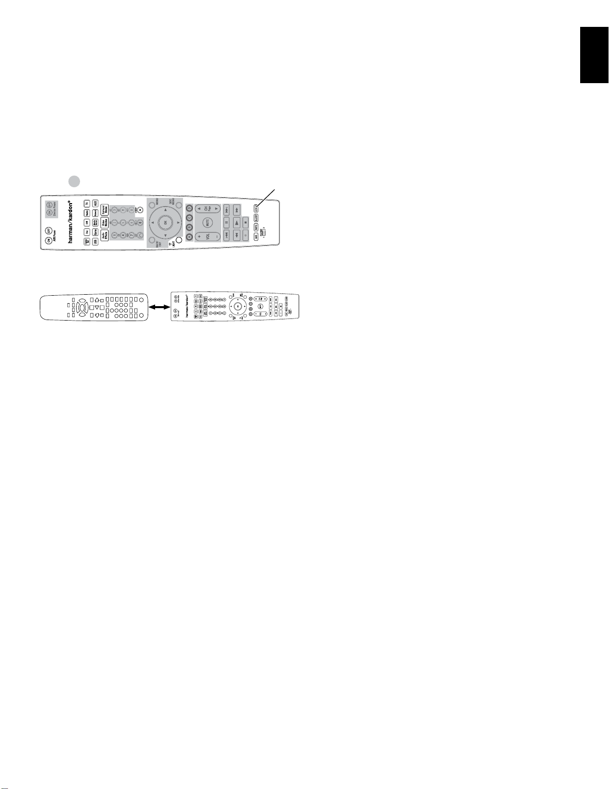
AVR
Learning (AVR 3700/AVR 370 only)
If you have the device’s original remote control, you may “teach” its individual button
codes into the following “destination” buttons on the AVR 3700/AVR 370 remote:
Device Power On/Off buttons, Number buttons, Last button, Back/Exit button, Menu
button, Up/Down/Left/Right buttons, OK button, Disc Menu button, A/B/C/D buttons,
Channel Up/Down buttons, Volume Up/Down buttons, Mute button, Transport Control
buttons.
Set Up the Remote Control
ENGLISH
= Destination Buttons
1. Place the two remotes with their IR transmitters facing each other, about 1 inch
(25mm) apart.
1 inch
(25mm)
2. Press the AVR remote’s Source Selector button for the source device, then press and
hold the Learn button until the Source Selector button glows red. The remote is now
in the Learning mode.
3. On the AVR remote, choose a destination button that will learn the source device
remote’s function. Press the destination button, and the Source Selector will flash
once.
4. On the source device’s remote, press and hold the button with the function that you
want to teach to the AVR remote until the Source Selector button flashes three times.
The source device remote’s button has now taught the AVR remote’s destination button
to perform its function on that source.
5. You can program additional buttons for this source by repeating Steps 3 – 4. You can
program buttons for other sources by repeating Steps 1 – 4.
When you’re finished, press the Learn button once to exit the Learning mode, or wait for
the remote to exit the Learning mode on its own after about 30 seconds.
Learn
Button
25
Page 31

AVR
Main Power
Switch
Power
Button
Set Up the AVR
Set Up the AVR
In this section, you will configure the AVR to match your actual system’s makeup.
Although it’s possible to configure the AVR using only the remote and the messages on
the AVR’s front-panel display, it is easier if you use the full-screen menu system.
Turn On the AVR
1. Set the rear-panel Main Power switch to “On.” (The front-panel Power indicator will
glow amber.)
2. Press the front-panel Power button.
Main Power
Switch
Unless you will not be using the receiver for an extended period of time, leave the Main
Power switch set to “On.” When the Main Power switch is turned off, any settings you
have programmed will be preserved for up to four weeks.
IMPORTANT NOTE:
turn off the AVR and unplug it. Check all speaker wires for a short-circuit (“+” and
“–“ wires touching). If none is found, bring the unit to an authorized Harman Kardon
service center for inspection and repair before using it again.
If the PROTECT message ever appears in the Message Display,
Power
Button
The Main Menu system consists of six submenus: Source Select, Setup Source, Speaker
Setup, Zone 2, System and Settings Lock. Use the Up/Down/Left/Right buttons on the
remote or the front panel to navigate the menu system, and press the OK button to select
a menu or setting line, or to enter a new setting.
The current menu, setting line or new setting will appear in the front-panel Message
Display, as well as on screen.
To return to the previous menu or exit the menu system, press the Back/Exit button. Be
certain all settings are correct, as any changes you have made will be retained.
Most users should follow the instructions in this Set Up the AVR section to configure a
basic home theater system. You may return to these menus at any time to make additional
adjustments, such as those described in the Advanced Functions section, on page 33.
Before beginning the following setup steps, all loudspeakers, a video display and all
source devices should be connected. You should be able to turn on the AVR and view the
main menu when you press the AVR button. If necessary, reread the Making Connections
and Set Up the Remote sections before continuing.
Configure the AVR for Your Speakers
1. Plug the supplied EzSet/EQ microphone into the AVR’s Headphone connector.
AVR
Headphone
Connector
Using the On-Screen Menu System
To access the menu system, press the AVR button on the remote or the Setup button on
the front panel. The Main Menu will appear, and if a video source is playing, it will be
visible behind the menu.
Source Select
Select the Source Device
Setup Source
Setup Source Devices
Speaker Setup
Speaker Optimization, EQ
Zone 2
Manage and Control Zone 2
System
General AVR Settings
Settings Lock
Manage System Lock
NOTE:
When you are using the AVR’s on-screen menu system, we recommend a video
output resolution of 720p or higher for easiest viewing and for graphics that simplify
some configuration options. Depending on the resolution selected, the menus shown by
your system may vary in appearance from the illustrations.
EzSet/EQ
Microphone
(supplied)
2. Place the microphone at ear height in your listening position. The microphone features
a threaded insert on the bottom for mounting on a camera tripod.
3. Set the volume control on your subwoofer to approximately the halfway point.
4. Turn on your TV and select the TV input where you connected the AVR in Connect Your
TV or Video Display, on page 17.
26
Page 32

AVR
Set Up the AVR
ENGLISH
5. Press the remote control’s AVR button. The AVR’s on-screen display (OSD) Main Menu
screen will appear on the TV.
Source Select
Select the Source Device
Setup Source
Setup Source Devices
Speaker Setup
Speaker Optimization, EQ
Zone 2
Manage and Control Zone 2
System
General AVR Settings
Settings Lock
Manage System Lock
6. Use the remote’s Up/Down/Left/Right and OK buttons to select “Speaker Setup.”
Speaker Setup
Automatic Setup – EzSet/EQ
Automated Speaker Setup and EQ
Manual Setup
Manually Adjust Speaker Settings
7. Select “Automatic Setup – EzSet/EQ” and then select “Continue.”
8. Select the number of speakers in your system. Select “5.1” if no surround back or
front height speakers are present or if you will be using the Assigned Amp channels
for multizone operation.
9. The test will begin. Make sure that the room is quiet while the test noise is playing
through the speakers.
10. When the test finishes, select “Continue,” then select “View Settings” to see the
results of the EzSet/EQ process, or select “Done” to exit.
NOTES:
• If there are fewer than five main speakers in your system, do not use the EzSet/
EQ process. Instead, proceed as described in Manual Speaker Setup, on page 36.
• If you are using a 6.1-channel configuration with a single surround back speaker,
use EzSet/EQ automatic configuration for 5.1 speakers, connect the single surround
back speaker to the left Assigned Amp Speaker Output connector, then configure
the surround back speaker manually, as described in Manual Speaker Setup, on
page 36.
Set Up Your Sources
The Setup Source menu lets you assign the correct physical audio and video connections
to each source and lets you set many audio and video playback features for each source.
IMPORTANT: The “Video Input from Source,” “Audio Input from Source” and
“Resolution to Display” settings are not optional and must be adjusted before
you use your AVR to enable playback of each source.
settings later. See System Settings, on page 39, for complete information about adjusting
all of the Settings menu options.
1. Review the assigned connectors you listed on the Source Buttons and Assigned
Connectors table, on page 18. Note what changes (if any) you want to make from the
default source-button connector assignments that appear on the list. (If there are no
changes, you can skip this section.)
2. To display the Source Settings menu for the active source, press the Info button on
the front panel or remote. Or, from the Main Menu screen, select “Setup Source” and
select a source from the slide-in menu. The Settings menu for that source will appear.
Cable/Sat
Audio Effects
Video Modes:
Surround Modes:
Audio Format from Source:
Video Input from Source:
Audio Input from Source:
Resolution to Display:
Resolution from Source:
HDMI Bypass:
Change Name:
Adjust Lip Sync
Off
Auto Select
NO AUDIO INPUT
HDMI 2
HDMI 2
720p – 60Hz
No Input
Off
Cable/Sat
3. Select “Video Input From Source” and select the video input connector you want to assign
to the source button. Press the OK button. NOTE: If you select an HDMI connector as the
Video Input from Source, the Audio Input from Source will automatically change to the
same HDMI connector. If you want to use a different audio connection, proceed to step 4.
Cable/Sat
Audio Effects
Video Modes:
Surround Modes:
Audio Format from Source:
Video Input from Source:
Audio Input from Source:
Resolution to Display:
Resolution from Source:
HDMI Bypass:
Change Name:
Adjust Lip Sync
Zone 2 Audio:
Off
Auto Select
No Audio Input
HDMI 2
HDMI 2
1080p – 60Hz
No Video Input
Auto
Cable/Sat
Analog 1
You can adjust the other
HDMI 1
HDMI 2
HDMI 3
HDMI 4
HDMI 5
HDMI 6
HDMI 7
HDMI Front
Component
Composite 1
27
Page 33

AVR
Set Up the AVR
4. Select “Audio Input from Source” and select the audio input connector you want to
assign to the source button. Press the OK button.
Cable/Sat
Audio Effects
Video Modes:
Surround Modes:
Audio Format from Source:
Video Input from Source:
Audio Input from Source:
Resolution to Display:
Resolution from Source:
HDMI Bypass:
Change Name:
Adjust Lip Sync
Zone 2 Audio:
Resolution to Display:
Off
Auto Select
No Audio Input
Component
Coaxial
1080p – 60Hz
No Video Input
Auto
Cable/Sat
Analog 1
This setting reflects the video output resolution, which is
HDMI 4
HDMI 5
HDMI 6
HDMI 7
HDMI Front
Optical 1
Optical 2
Coaxial
Analog 1
Analog 2
dependent upon the capabilities of your TV or video display.
• If you connected your TV to the AVR’s HDMI Monitor Out connector, the two devices
will communicate with each other, and the AVR will automatically select the best
available video output resolution. In almost all cases, you should leave the resolution
set to the AVR’s automatic selection. (You can override this automatic selection if
your video display’s native resolution is different from the AVR’s automatic selection.)
• If you connected your TV to the AVR’s Composite Video Monitor Out connector, you
must set the resolution to “480i” (AVR 3700/AVR 2700) or to “576p” (AVR 370/AVR
270) to view any content.
NOTE: If your connected TV is 4K video capable, the AVR will automatically pass 4K
video sources through to the TV in their native resolution and will upscale non-4K video
sources up to 4K.
Audio Effects:
This submenu allows you to adjust the Dolby Volume and Dolby PLII/IIx/
IIz settings, the bass and treble tone controls, the LFE trim and the Equalization On/Off
setting for each source independently. We suggest leaving this submenu at its default
settings and returning to it later if your system requires fine-tuning. See Audio Effects
Button, on page 34, for more information.
Video Modes:
This submenu allows you to make picture adjustments for each source
independently. We suggest leaving the settings at their factory defaults. You should make
picture adjustments to your video display first and use this menu only for fine-tuning. See
Video Processing, on page 34, for more information.
Surround Modes:
This submenu lets you program surround modes for movies, music
and games for each source independently. Digital surround signals, such as Dolby Digital
and DTS bitstreams, are automatically played in their native formats, although you may
change the surround mode. See Audio Processing and Surround Sound, on page 33, for
more information.
Audio Format from Source:
This line is informational only. When a digital program is
playing, its format will be identified here. When analog audio programs are playing, this
line displays ANALOG.
Resolution from Source:
This line is informational only. It indicates the resolution of the
video output by the source device.
HDMI Bypass:
This setting allows you to bypass the AVR’s internal video processing for
proper display of 3D video content and of source devices (such as some game consoles)
where the AVR's video processing can create delays that can cause synchronization
errors between the sound and picture. There are two available settings:
•On:AlwaysbypassestheAVR'sinternalvideoprocessing.
•Auto:AutomaticallybypassestheAVR'sinternalvideoprocessingwhen 3Dcontentis
detected.
IMPORTANT: Once the AVR automatically switches into the bypass mode upon detecting
3D video content, it will not automatically switch out of the bypass mode when it detects
conventional 2D video content. To turn the HDMI Bypass off you must cycle the AVR into
the Standby mode and then turn it on again.
We suggest that you create an additional source configuration for each of your 3D video
source devices by assigning each an unused Source Selector button on the AVR’s remote
control. For example, you can assign the AVR’s “Media Server” source as the 3D source
for a 3D-capable disc player or game, and you can assign one of the AVR’s “A/B/C/D”
source buttons as the 3D source for your cable or satellite tuner’s 3D programming.
Creating “HDMI Bypass” Inputs
In this example, we will program the Media Server source as an HDMI Bypass source for
3D programming:
1. Select “Setup Source.” The source list will appear.
2. Select “Media Server.” The Media Server setup screen will appear.
3. Select “HDMI Bypass.” A confirmation screen will appear.
4. Select “OK.” The AVR will exit the menu mode.
Repeat Steps 1 – 4, assigning a new 3D source for each of your 3D-capable source
devices.
Notes:
• When using your AVR with these new settings, be sure to press the correct
source selectors for your 2D and 3D sources.
• If you are viewing 3D sources when an HDMI Bypass input is active, the onscreen indications for volume level will not appear. This is normal, since all video
processing is removed in the HDMI Bypass mode.
• If your video sources are always operating at 720p or higher resolution, you
may find the HDMI Bypass mode acceptable for normal 2D viewing as well
as for 3D viewing. In this case, you may find it more convenient to use the 3D
sources at all times.
• If you see side-by-side or top-and-bottom images while watching a 3D program,
manually switch to the HDMI Bypass mode.
Change Name: This selection lets you change the display name for the source, which
is useful if your source’s device type is different from the source’s preprogrammed
name. Select this line and use the Up/Down buttons to scroll forward or reverse through
the alphanumeric characters. When the desired character appears, use the Left/Right
buttons to move the cursor to the next or previous position. Move the cursor again to
leave a blank space. When you have finished, press the OK Button. The name will appear
on the AVR’s front panel and throughout the on-screen menu system.
Adjust Lip Sync: This selection lets you resynchronize the audio and video signals from
a source to eliminate a “lip sync” problem. Lip-sync issues can occur when the video
portion of a signal undergoes additional processing in either the source device or the
video display. When you make a Lip Sync adjustment, the Lip Sync menu appears by
itself, enabling you to view the video while listening to the audio. Use the Left/Right
buttons to delay the audio by up to 180ms.
Adjust Lip Sync
ms
15
Zone 2 Audio: This setting determines the audio source for Zone 2 of a multizone
system. Select the analog audio input the source is connected to. Digital audio is not
available to the multizone system.
To configure the next source, press the Back/Exit button, then return to the Setup Source
line of the Main Menu. When you have finished configuring all sources, press the Back/
Exit button to clear the menus from view.
Set Up the Network
To play MP3 or WMA media located on DLNA-compatible devices connected to the
network, use the AVR’s internal Internet radio tuner or listen to sources via AirPlay, the
AVR must be connected to your home network and you must join them with the network.
(If your home network is Wi-Fi, the AVR 3700 and AVR 370 can connect to it wirelessly.)
28
Page 34

AVR
Set Up the AVR
ENGLISH
Wired Network Setup
If your network uses an automatic IP address, you should not have to perform any
network setup procedures for a wired network connection. Once you connect the AVR to
your home network, the network should automatically assign the AVR an IP address, and
the AVR should automatically connect to your network.
If your AVR does not automatically connect to your network (in which case the AVR will
display a “Not Connected” message when you press the Network source button):
1. Press the AVR button, select System, then select Network Settings. The Wired/Wireless
selection screen will appear.
2. Select Wired. The Wired Network Settings menu will appear.
Network Settings
Mac
Network Settings:
IP Address:
Subnet Mask:
Gateway:
Primary DNS:
Secondary DNS:
Proxy
IP Address:
Proxy Port:
Network Status:
Apply & Save
0x:00:0x:00:0x:0x
Automatic
000 . 000 . 000 . 000
000 . 000 . 000 . 000
000 . 000 . 000 . 000
000 . 000 . 000 . 000
000 . 000 . 000 . 000
Off
000.000.000.000
00000
Connected
3. Select Network Settings, the press the OK button twice to cycle the setting from
“Automatic” to “Manual” and back to “Automatic.”
4. Select Apply & Save. The AVR will attempt to connect to the network.
5. If the AVR again fails to connect to the network, you may need to enter your network’s
settings manually. See Network Settings (under General AVR Settings), on page 40, for
complete instructions. You may need to obtain your network’s settings from your ISP
or network administrator.
NOTE: We recommend that you directly connect the AVR to a home-network router so
that it can directly access the Internet for Internet radio, or access a PC on the network
for playback of content stored on the PC (see Listening to Media via Your Home Network,
on page 32, for more information).
The following options appear in the Wireless Setup menu:
• Search AP: Select this option to display and select the wireless network you wish
to join.
• Information: Select this option to display the settings information for the active
wireless network. This screen is informational only – you cannot make changes in
the network settings from it.
• iPod Network Setup: Selecting this option lets you use your portable device with iOS
5 or later to automatically have the AVR join the same wireless network to which
the device is already connected. See Using your iOS 5 device to join the wireless
network, below, for details.
• AVR AP Mode: This option provides an alternate method for connecting to a wireless
network without using the AVR’s on-screen display.
NOTE: If you have already made a connection to a wired network you will not be able to
select the Wireless setting. Disconnect the AVR from the wired network and begin again
at Step 1.
3. Select Search AP and select the network you wish to join from the ones displayed. The
Enter Password screen will appear.
4. Use the remote’s up and down arrow buttons to select each character in your Wi-Fi
network’s password. (The characters will appear on the AVR’s front-panel display and
the OSD screen.) When you have selected the correct character, use the right arrow
button to move to the next one. If you make a mistake, use the left arrow button to
change a previous character.
5. Once the correct password is displayed on the AVR’s front-panel display and the OSD
screen, press the OK button. The AVR will attempt to join the network.
6. When the AVR has successfully joined the network it will display “Connection Success”
on its front-panel display and OSD.
• If the AVR is not able to join the network it will display “Connection Failure.” If this
happens, confirm that you entered the correct password, attempt to connect to
another wireless network or make a wired network connection.
Using your iOS 5 device to join the wireless network:
1. Make sure that your iOS 5 device is joined with the wireless network you want the
AVR to join.
2. Connect your iOS 5 device to the AVR’s front-panel USB port.
3. The iPod Network Setup option described in Step 2, above, will become available.
Select it.
4. The AVR will automatically join the network without requiring further input from you.
Wireless Network Setup (AVR 3700/AVR 370)
If you want to join the AVR to your Wi-Fi network you will need to perform the following
setup procedure.
1. Press the AVR button, select System, then select Network Settings. The Wired/Wireless/
Network Upgrade selection screen will appear.
2. Select Wireless. The Wireless Network Settings menu will appear.
Network Settings
Search AP
Information
iPod Network Setup
AVR AP Mode
29
Page 35

AVR
Operating Your AVR
Operating Your AVR
Now that you have installed your components and completed a basic configuration, you
are ready to begin enjoying your home theater system.
HARMAN AVR App
For easy control of your AVR with your hand-held device, download the free Harman
Kardon AVR app from iTunes App Store for compatible Apple products, or from Google
Play for compatible Android powered smartphones and tablets.
The Harman Kardon AVR App controls virtually all the functions of AVR 3700, AVR 370,
AVR 2700 and AVR 270 receivers that are connected to the same network as the device
that has the app installed. With this easy-to-use app you can turn the AVR on or off, select
a source, control the volume and virtually any other function. You can also access and
navigate all of the AVR’s on-screen setup menus.
Controlling the Volume
Adjust the volume either by turning the front-panel Volume knob (clockwise to increase
volume or counterclockwise to decrease volume) or by pressing the Volume Up/Down
buttons on the remote. The volume is displayed as a negative number of decibels (dB)
below the 0dB reference point (-90dB – +10dB).
0dB is the maximum recommended volume for your AVR. Although it’s possible to turn
the volume to a higher level, doing so may damage your hearing and your speakers. For
certain more dynamic audio materials, even 0dB may be too high, allowing for damage
to equipment. Use caution with regard to volume levels.
To change the volume level display from the default decibel scale to a 0-to-90 scale,
adjust the Volume Units setting in the System Settings menu, as described in System
Settings, on page 39.
Muting the Sound
To mute all speakers and the headphones, press the Mute button on the remote. Any
recording in progress will not be affected. The MUTE message will appear in the display
as a reminder. To restore the sound, press the Mute button again, or adjust the volume.
Dolby Volume
Your AVR implements Dolby Volume processing, which can improve the audio performance
of the system by revealing subtle details in the sound, even at normal home-listening
volumes.
One concern of the typical home theater listener is that volumes can vary widely for
different programs played by a source (e.g., television commercial advertisements are
often much louder than the main program). Another is that details heard in the recording
studio at typically high reference volumes are lost at the lower volumes used by many
listeners at home.
The AVR uses two Dolby Volume techniques to address these issues. The Leveler module
maintains a consistent listening volume within a source (e.g., commercial television or
different tracks on a USB drive or mix CD). The Modeler module endeavors to re-create
the reference presentation that was heard in the recording studio without losing portions
of the program at the typically lower volume levels often used in the home. When the
Modeler module is active, you may notice details of the performance that were hidden
when the program was played on other equipment.
To adjust the Dolby Volume setting, press the Audio Effects button. The Audio Effects
submenu will appear.
After you highlight the Dolby Volume setting, each press of the OK button will switch to
one of the options in the table below. The settings do not refer to the volume level, which
is adjusted normally using the AVR’s Volume Control, but rather to the amount of Dolby
Volume processing desired.
Setting Effect
Off No Dolby Volume processing
Low Only Dolby Volume Modeler module is active
Medium
Max
NOTE: Dolby Volume processing is compatible with sources recorded at a sampling
rate of 48kHz. High-resolution sources, such as DTS 96/24 programs, will be
decoded at 48kHz. DTS 96/24 programs will be played in DTS 5.1 mode. To hear
DTS 96/24 materials in high resolution, turn off Dolby Volume processing.
Dolby Volume Calibration
Dolby Volume calibration allows you to adjust the operation of the Dolby Volume
circuitry to match your particular speakers and listening environment. The Dolby Volume
circuitry in your AVR is factory-calibrated with average speaker sensitivity in mind;
however, different speakers may have different sensitivities, which will affect the overall
performance of the Dolby Volume circuitry. Use Dolby Volume calibration to adjust the
calibration of the circuitry according to the specific speakers you have.
The average home audio speaker sensitivity is 88dB SPL (1 watt/1 meter). Check the
sensitivity specification for your loudspeakers, found in the owner’s manual or on the
manufacturer’s Web site. If your speakers have a sensitivity rating greater than 88dB SPL,
increase Dolby Volume calibration by the difference between your speakers’ sensitivity
and 88dB. If they have a sensitivity rating of less than 88dB SPL, decrease Dolby Volume
calibration by the difference between your speakers’ sensitivity and 88dB.
To adjust the Dolby Volume calibration, press the AVR button and select the “System”
menu. Scroll to the Dolby Volume calibration line, which defaults to 0dB. Use the Left/
Right buttons to adjust the setting within the range of –10dB to +10dB.
Both Modeler and Leveler modules are active;
Leveler module has a value of 3
Both Modeler and Leveler modules are active;
Leveler module has a value of 9
Listening Through Headphones
Plug the 1/4-inch stereo plug on a pair of headphones into the front-panel Phones jack
for private listening. The default Headphone Bypass mode delivers a conventional twochannel signal to the headphones. Press the Surround Modes button on the front panel
or the remote to switch to HARMAN headphone virtual surround processing, which
emulates a 5.1-channel speaker system. No other surround modes are available for the
headphones.
Audio Effects – Cable/Sat
Dolby Volume:
PLIIz Height Gain:
Edit: Dolby PLII Music
Edit: Dolby PLIIx Music
Tone Control:
Treble:
Bass:
LFE Trim:
EZSET/EQ:
30
Medium
Low
On
Off
Page 36

AVR
Operating Your AVR
ENGLISH
Selecting a Source
There are three different ways to select a source:
• Press the front-panel Source List button. Use the Up/Down buttons to scroll through
the sources, and press the OK button to select the source being displayed.
• Using the on-screen menus, press the AVR button, highlight “Source Select” and
press the OK button. Scroll to the desired source in the slide-in menu and press the
OK button.
• You can directly select any source by pressing its Source Selector button on the
remote.
The AVR selects the audio and video inputs assigned to the source, and any other settings
you made during setup.
The source name, the audio and video inputs assigned to the source, and the surround
mode will appear on the front panel. The source name and active surround mode will also
briefly appear on the TV screen.
Video Troubleshooting Tips
If there is no picture:
• Check the source selection and video input assignment.
• Check all connections for a loose or incorrect connection.
• Check the video input selection on the TV/display device.
• Press the front-panel Resolution button and use the Up/Down buttons until the
correct video output resolution is selected and a picture appears. The CANCEL
message will also appear. Press the Down button to view the ACCEPT option,
then press the OK button.
Additional Tips for Troubleshooting HDMI Connections
• Turn off all devices (including the TV, the AVR and any source components).
• Unplug the HDMI cables, starting with the cable between the AVR and the TV,
and continuing with the cables between the AVR and each source device.
• Carefully reconnect the cables from the source devices to the AVR. Connect the
cable from the AVR to the TV last.
• Turn on the devices in this order: TV, AVR, source devices.
NOTE: Depending upon the particular components involved, the complexity of
the required communication between HDMI components may cause delays of
up to a minute in the completion of some actions, such as input switching or
switching between SD and HD channels.
Listening to FM and AM Radio
Select the Radio source. A screen similar to the one in the illustration below will appear.
AM/FM Radio
1
87.50
FM
MHz
Auto
Menu: Set Presets: Presets:
Use the Up/Down buttons or the Remote’s Channel buttons to tune a station as displayed
on the front panel and on-screen display.
The AVR defaults to automatic tuning, meaning each press of the Up/Down buttons scans
up or down the frequency band until a station with acceptable signal strength is found.
To switch to manual tuning, in which each press of the Up/Down buttons steps through
a single tuning frequency increment, press the remote’s Menu button. A slide-in menu
will appear. Select “Mode,” and press the OK button to toggle between automatic and
manual tuning modes.
Once you have tuned an FM station, toggling the Mode setting also switches the radio
between stereo and monaural reception. (Mono reception may improve reception of
weaker stations.)
Preset Stations
You can store a total of 30 stations (AM and FM combined) as presets. When you want
to save the currently tuned station as a preset, press the OK button, and two dashes will
flash. Use the Number buttons to enter the desired preset number.
To tune to a preset station:
• Press the Left/Right buttons.
• Press the skip forward/skip backward Transport Control buttons.
• Press the Menu button and scroll to the desired preset, then press the OK button.
• Enter the preset number using the Number buttons. For presets 10 through 30, press
0 before the preset number. For example, to enter preset 21, press 0-2-1.
OKMENU
Listening to Media on a USB Device
Your AVR is compatible with MP3 and WMA media.
MP3 compatibility: Mono or stereo, contstant bit rates (CBR) from 8kbps to 320kbps,
variable bit rates (VBR) from lowest to highest quality, with sample rates from 8kHz –
48kHz.
WMA compatibility: Ver. 9.2, stereo CBR with 32kHz – 48kHz sampling rate and 40kbps
– 192kbps bit rate, mono CBR with 8kHz – 16kHz sampling rate and 5kbps – 16kbps bit
rate, VBR Pass Encoding and Quality Encoding 10 – 98, 44kHz and 48kHz sampling rate.
No other types of media can be played.
31
Page 37

AVR
:N
:N
:N
Operating Your AVR
Playing files on a USB device
1. Insert the USB drive into the AVR’s front-panel USB port.
IMPORTANT: Do not connect a personal computer or peripheral to the USB port. USB
hubs and multi-card readers are not supported.
2. Select the USB Source Selector button on the remote. “USB” will appear on the frontpanel display, and the USB screen and the slide-in menu will appear.
USB
Menu:Previous
MENU
USB
Browse USB
Repeat Music: Off
ext:
3. Select “Browse USB.” The AVR will list the folders located on the drive.
4. Select a folder and press the OK button. The AVR will list all compatible audio files.
5. Select a file to begin playback. The USB play screen will appear. Any ID3 information
and album art will be displayed, along with the track’s elapsed/current time and icons
indicating the current playback status.
USB
Night Crazy
Jugalbandi
Night Crazy
06:16
Menu:Previous
MENU
NOTES:
• To skip to the next track, press the Right button; to return to the previous track, press
the Left button once.
• You can use the Transport Control buttons to control playback (skipping to the
previous or next track, searching at high speed forward or backward within a track,
playing a file, pausing playback or stopping playback).
• To repeat a file or folder, press the Menu Button and select the Repeat option. Each
press of the OK Button will change the setting from Off (no repeat) to Repeat One
(file) to Repeat All (files at the current directory level of the drive). Repeat All will
always be activated when Random Music playback is turned on.
• To play the audio tracks in random order, press the Menu button and select the
Random Music setting. Each press of the OK button turns the setting on or off. The
AVR will automatically repeat the tracks until playback is stopped manually.
• To collapse a folder or return to the previous menu level, press the Back/Exit button
or the Left button.
ext:
Listening to an iPod/iPhone/iPad Device
When an iPod, iPhone or iPad device is connected to the AVR’s front-panel USB port, you
may play audio files through your high-quality audio system, operate the iPod, iPad or
iPhone using the AVR remote or the AVR’s front-panel controls, view navigation messages
on the AVR’s front panel or a connected video display and charge the iPod, iPad or iPhone.
For the latest compatibility information, please see our Web site: www.harmankardon.com.
Press the USB source selector button on the remote until the front-panel display’s “iPod”
as the source. The iPod screen will appear and the slide-in menu will automatically
appear.
iPod
Menu:Previous
MENU
The table below summarizes the controls available during normal playback via the USB
port.
iPod or iPhone Function Remote Control Key
Play Play
Pause Pause
Menu Menu
Back/Exit Back/Exit or Left Arrow
Select OK or Right Arrow
Scroll Reverse Up Arrow
Scroll Forward Down Arrow
Forward Search Forward Search
Reverse Search Reverse Search
Next Track Skip Forward or Right Arrow
Previous Track Skip Backward or Left Arrow
Page Up/Down Page Up/Down
While scrolling, hold the button to scroll faster. Use the Page Up/Down control on the
remote to scroll a page at a time.
While a selection is playing, the album, artist, song title, track elapsed time, total track
time and play mode icon will appear on the front-panel Message display.
iPod
Music
Repeat Music:Off
Shuffle Music:Off
ext:
32
Page 38

AVR
:N
Operating Your AVR
ENGLISH
If a video monitor is connected to the AVR and the system is not in iPod manual mode,
an iPod screen will appear and display the play mode icon, song title, artist and album. A
graphic bar indicates the current play position within the track. If random or repeat play
has been programmed, an icon will appear in the upper right corner.
iPod
Menu:Previous
MENU
iPod
Music
Repeat Music:Off
Shuffle Music:Off
ext:
The screen may disappear from view, depending on the Setup and Slide-In Menus setting
in the System Settings menu (described in System Settings, on page 39). You can restore
the Now Playing screen to view by pressing either of the Left or Right buttons.
CAUTION: We strongly recommend that you use the screen saver built
into your video display to avoid possible damage from “burn-in” that may
occur with plasma and many CRT displays when a still image, such as a
menu screen, remains on the display for an extended period of time.
Press the Menu button to view the slide-out menu:
Music: Select this to navigate the audio materials stored on the iPod, iPad or iPhone. Use
the Page up/down buttons on the remote to scroll through the content a page at a time.
NOTE: You can only play audio content via the USB port.
Repeat Music: Select this setting to repeat a track or all tracks in the current album
or playlist. Each press of the OK button switches the setting: repeat Off, repeat One or
repeat All.
Shuffle Music: Select this setting to play all the available songs in random order. Each
press of the OK button switches the setting: shuffle by Song, shuffle by Album, or Off to
end shuffle playback.
NOTE: The iTunes application allows you to exempt some tracks from Shuffle mode. The
AVR cannot override this setting.
Listening to vTuner (Internet Radio)
Your AVR’s Network connection brings you a world of MP3- and WMA-format streams via
the Internet. After you have successfully connected to your home network as described in
Connect to Your Home Network, on page 20, and set up the network as described in Set
Up the Network, on page 27, press the Network Source Selector button on the remote.
Each press toggles between the Network and vTuner screens.
vTuner
Jugalbandi - Night Crazy
Laut fm Progman
11:43
Menu:Previous: Next:
MENU
With the vTuner screen (above) displayed, the AVR will automatically connect to the
Internet via the www.radioharmankardon.com portal. To select a stream, press the Menu
button, and use the Up/Down buttons to search by category: Presets, My Favourites,
Added Stations, Location, Genre, Podcasts by Location, Podcasts by Genre, New Stations,
Most Popular Stations, Recently Played and Search. NOTE: The categories displayed may
vary by region.
To create a Favourites list, log onto www.radioharmankardon.com from your computer.
Enter your AVR’s Mac address as its ID # (the Mac address is on the Network Settings
screen in the System Settings menu) and create an account. Favourites that you select
on the Web site will be available on the AVR.
Navigation is similar to other slide-in menus. Scroll to the desired item and press the OK
button to select it. To return to the previous menu level (or to clear the top-level menu
from view), press the Back/Exit button or the Left button.
If you know the URL (Web address) of a specific audio stream, select the Direct Station
option from the menu. A live stream is required. The AVR is not able to connect to streams
that require site registration or other interaction prior to playing the stream. If the AVR
cannot connect to the stream, a “Station Not Live” message will appear briefly, and the
Internet Radio screen will remain essentially blank. Not all URLs will be accessible.
Listening to Media via Your Home Network
Your AVR is DLNA-compatible and can access MP3 and WMA audio media that is stored
on other DLNA-compatible devices that are connected to the same network as your AVR.
DLNA is a file sharing protocol that creates a bridge between the AVR and other devices
on the same network that contain audio media. DLNA is supported by PCs that have
Windows Media Player, Windows Media Center or Intel Media Server file sharing. Apple
computers can also share files via DLNA using HARMAN Music Manager software, which
can be downloaded without charge from www.harmankardon.com. (Third-party software
that enables DLNA file-sharing also is available.)
MP3 compatibility: Mono or stereo, contstant bit rates (CBR) from 8kbps to 320kbps,
variable bit rates (VBR) from lowest to highest quality, with sample rates from 8kHz –
48kHz.
WMA compatibility: Ver. 9.2, stereo CBR with 32kHz – 48kHz sampling rate and 40kbps
– 192kbps bit rate, mono CBR with 8kHz – 16kHz sampling rate and 5kbps – 16kbps bit
rate, VBR Pass Encoding and Quality Encoding 10 – 98, 44kHz and 48kHz sampling rate.
Before you can access files located on other devices via the network, each device
must first give permission to share files with the AVR:
33
Page 39

AVR
:N
Operating Your AVR
To share media on PCs:
1. Open Windows Media Player.
2. Open the Library menu and select Media Sharing. The Media Sharing window will
appear.
3. Check the “Share My Media” box. An icon for the AVR will appear in the window.
4. Select the AVR icon, select “Allow,” then select “OK.”
The computer’s WMA and MP3 media should now be available to the AVR.
To share media on other types of computers, operating systems or media software:
Check the instructions for the computer, operating system or media player.
To listen to shared media, press the Network Source Selector button. (If vTuner appears
as the source, press the button a second time to switch from the Internet Radio source to
the Network source.) The Network screen will appear.
Network
Beanwater Junction
Jugalbandi
Night Crazy
1.50
Menu:Previous
MENU
Press the Menu button, and the slide-in menu should list by name all devices that allow
sharing. Use the slide-in menu to browse the content stored in the device’s media player
library. Scroll to the desired item and press the OK button to select it. To return to the
previous menu level (or to clear the menu from view from the top level), press the Back/
Exit button or the Left button.
NOTE: Although video content may appear in the menu, the AVR does not support video
playback from the network connection.
ext:
Selecting a Surround Mode
Selecting a surround mode can be as simple or sophisticated as your individual system
and tastes. Feel free to experiment, and you may find a few favorites for
or program types. You can find more detailed information on surround modes in
Audio Processing and Surround Sound, on page 33.
To select a surround mode, press the Surround Modes button (front panel or remote). The
Surround Modes menu will appear.
Surround Modes – Cable/Sat
certain sources
Stereo: When you want two-channel playback, select the number of speakers you want
to use for playback:
• “2 CH Stereo” uses two speakers.
• “5 CH Stereo” plays the left-channel signal through the front left and surround
left speakers, the right-channel signal through the front right and surround right
speakers, and a summed mono signal through the center speaker.
• “7 CH Stereo” follows the same scheme as 5 CH Stereo but adds the surround
back left and surround back right speakers. This mode is available only when the
surround back speakers are present and have not been reassigned to multizone or
front height operation. See Audio Processing and Surround Sound, on page 33, for
more information.
Movie: Select from the following when you want a surround mode for movie playback:
Logic 7 Movie, DTS Neo:6 Cinema or Dolby Pro Logic II (IIx or IIz when seven main
speakers are present).
Music: Select from the following when you want a surround mode for music playback:
Logic 7 Music, DTS Neo:6 Music or Dolby Pro Logic II (IIx or IIz when seven main speakers
are present). The Dolby Pro Logic II/IIx/IIz Music mode allows access to a submenu with
some additional settings. See Audio Processing and Surround Sound, on page 33, for
more information.
Video Game: Select from the following when you want a surround mode for game
playback: Logic 7 Game or Dolby Pro Logic II (IIx/IIz when seven main speakers are
present) Game.
After you have made your selection, press the Back/Exit button.
See Audio Processing and Surround Sound, on page 33, for more information on surround
modes.
Audio Effects
The Audio Effects buttons on the front panel and remote provide settings that let you
adjust the Dolby Volume setting, tone controls, LFE trim or EZ Set, Equalization On/Off
setting. We recommended that you leave these settings at their default values until you
are more familiar with your system. See Audio Effects Button, on page 34, for complete
information.
Video Modes
The Video Modes buttons on the front panel and remote provide settings that let you
use the AVR’s video processor to fine-tune the picture, if necessary, after making all
adjustments on the video display. We recommend that you leave the settings at their
defaults until you are completely familiar with the video performance of your system. See
Video Processing, on page 34, for complete information.
Auto Select – AVR Selects Best Mode
Virtual Surround – For Two Speaker Systems
Stereo:
Movie:
Music:
Video Game:
Press the Up/Down buttons repeatedly until the desired surround-mode category
appears: Auto Select, Virtual Surround, Stereo, Movie, Music or Video Game. Press the OK
button to change the surround-mode category.
Auto Select: For digital programs, such as a movie recorded with a Dolby Digital or DTS
soundtrack, the AVR will automatically use the soundtrack’s native surround format. For
two-channel analog and PCM programs, the AVR uses the Logic 7 Movie, Logic 7 Music
or Logic 7 Game mode, depending on the source.
Virtual Surround: When only two main speakers are present in the system, you can use
HARMAN Virtual Surround to create an enhanced soundfield that virtualizes the missing
speakers. Select between Wide and Reference modes.
34
2 CH Stereo
Logic 7 Movie
Logic 7 Music
Logic 7 Game
Page 40

AVR
Advanced Functions
ENGLISH
Advanced Functions
Much of the adjusting and configuration your AVR requires is handled automatically, with
little intervention required on your part. You can also customize your AVR to suit your
system and your tastes. In this section we will describe some of the more advanced
adjustments available to you.
Audio Processing and Surround Sound
Audio signals can be encoded in a variety of formats that can affect not only the quality
of the sound but the number of speaker channels and the surround mode. You may also
manually select a different surround mode, when available.
Analog Audio Signals
Analog audio signals usually consist of two channels – left and right.
process two-channel audio signals to produce multichannel surround sound, even
when no surround sound has been encoded in the recording. Among the available
modes are the Dolby Pro Logic II/IIx/IIz, HARMAN Virtual Speaker, DTS Neo:6, Logic
7, 5 CH and 7 CH Stereo modes. To select one of these modes, press the Surround
Modes button.
Digital Audio Signals
Digital audio signals offer greater flexibility and capacity than analog signals, and
allow the encoding of discrete channel information directly into the signal. The result is
improved sound quality and startling directionality, since each channel’s information is
transmitted discretely. High-resolution recordings sound extraordinarily distortion-free,
especially in the high frequencies.
Surround Modes
Surround-mode selection depends upon the format of the incoming audio signal as well
as your personal taste. Although there is never a time when all of the AVR’s surround
modes are available, there is usually a wide variety of modes available for a given input.
Table A12 in the Appendix, on page 50, offers a brief description of each mode and
indicates the types of incoming signals or digital bitstreams the mode may be used with.
Additional information about the Dolby and DTS modes is available on the companies’
Web sites: www.dolby.com and www.dtsonline.com.
When in doubt, check the jacket of your disc for more information on which surround
modes are available. Usually, nonessential sections of the disc, such as trailers, extra
materials or the disc menu, are available only in Dolby Digital 2.0 (two-channel) or
PCM two-channel mode. If the main title is playing and the display shows one of these
surround modes, look for an audio or language setup section in the disc’s menu. Also,
make sure your disc player’s audio output is set to the original bitstream rather than
two-channel PCM. Stop play and check the player’s output setting.
Multichannel digital recordings are produced in five-channel, six-channel or sevenchannel formats, with or without a “.1” channel. The channels included in a typical
5.1-channel recording are front left, front right, center, surround left, surround right and
LFE (low-frequency effects). The LFE channel is denoted as “.1” to represent the fact that
it is limited to the low frequencies. 6.1-channel recordings add a single surround back
channel, and 7.1-channel recordings add surround back left and surround back right
channels to the 5.1-channel configuration. New formats are available in 7.1-channel
configurations. Your AVR is able to play the new audio formats, delivering a more exciting
home theater experience.
NOTE: To use the 6.1- and 7.1-channel surround modes, the surround back channels
must be enabled. See Manual Speaker Setup, on page 36 for more information.
Digital formats include Dolby Digital 2.0 (two channels only), Dolby Digital 5.1, Dolby
Digital EX (6.1), Dolby Digital Plus (7.1), Dolby TrueHD (7.1), DTS-HD High-Resolution
Audio (7.1), DTS-HD Master Audio (7.1), DTS 5.1, DTS-ES (6.1 Matrix and Discrete), DTS
96/24 (5.1), two-channel PCM modes in 32kHz, 44.1kHz, 48kHz or 96kHz, and 5.1 or
7.1 multichannel PCM.
When the AVR receives a digital signal, it detects the encoding method and the number
of channels, which is displayed briefly as three numbers, separated by slashes (e.g.,
“3/2/.1”).
The first number indicates the number of front channels in the signal: “1” represents
a monophonic recording (usually an older program that has been digitally remastered
or, more rarely, a modern program for which the director has chosen mono as a special
effect). “2” indicates the presence of the left and right channels, but no center channel.
“3” indicates that all three front channels (left, right and center) are present.
Your AVR is able to
The second number indicates whether any surround channels are present: “0” indicates
that no surround information is present. “1” indicates that a matrixed surround signal is
present. “2” indicates discrete left and right surround channels. “3” is used with DTS-ES
bitstreams to represent the presence of the discrete surround back channel, in addition
to the side surround left and right channels. “4” is used with 7.1-channel digital formats
to indicate the presence of two discrete side surround channels and two discrete back
surround channels.
The third number is used for the LFE channel: “0” indicates no LFE channel. “.1”
indicates that an LFE channel is present.
The 6.1-channel signals – Dolby Digital EX and DTS-ES Matrix and Discrete – each
include a flag that signals the receiver to decode the surround back channel, indicated
as 3/2/.1 EX-ON for Dolby Digital EX materials, and 3/3/.1 ES-ON for DTS-ES materials.
Dolby Digital 2.0 signals may include a Dolby Surround flag indicating DS-ON or DS-OFF,
depending on whether the two-channel bitstream contains only stereo information or a
downmix of a multichannel program that can be decoded by the AVR’s Dolby Pro Logic
decoder. By default, these signals are played in Dolby Pro Logic IIx Movie mode.
When a PCM signal is received, the PCM message and the sampling rate (32kHz,
44.1kHz, 48kHz or 96kHz) will appear.
When only two channels – left and right – are present, the analog surround modes
may be used to decode the signal into multiple channels. If you would prefer a different
surround format than the native signal’s digital encoding, press the Surround Modes
button to display the Surround Modes menu (see Selecting a Surround Mode, on page
32).
The Auto Select option sets the surround mode to the native signal’s digital encoding,
e.g., Dolby Digital, DTS, Dolby TrueHD or DTS-HD Master Audio. For two-channel
materials, the AVR defaults to the Logic 7 Movie mode. If you prefer a different surround
mode, select the surround-mode category: Virtual Surround, Stereo, Movie, Music or
Video Game. Press the OK button to change the mode.
Each surround-mode category is set to a default surround mode:
• Virtual Surround: HARMAN virtual speaker.
• Stereo: 7-CH Stereo or 5-CH Stereo (depending on how many main speakers are
present in the system).
• Movie: Logic 7 Movie.
• Music: Logic 7 Music.
• Video Game: Logic 7 Game.
You may select a different mode for each category. Below is a complete list of available
surround modes. (The actual surround modes available will depend on the number of
speakers in your system.)
• Virtual Surround: HARMAN virtual speaker.
• Stereo: 2-CH Stereo, 5-CH Stereo or 7-CH Stereo.
• Movie: Logic 7 Movie, DTS Neo:6 Cinema, Dolby Pro Logic II Movie, Dolby Pro Logic
IIx Movie, Dolby Pro Logic IIz.
• Music: Logic 7 Music, DTS Neo:6 Music, Dolby Pro Logic II Music, Dolby Pro Logic
IIx Music, Dolby Pro Logic IIz.
• Video Game: Logic 7 Game, Dolby Pro Logic II Game, Dolby Pro Logic IIx Game,
Dolby Pro Logic IIz.
Once you have programmed the surround mode for each type of audio, select the
line from the Surround Modes menu to override the AVR’s automatic surround-mode
selection. The AVR will use the same surround mode the next time the source is selected.
NOTE: Dolby Pro Logic IIx is available only if you have set up the AVR’s Assigned Amp to
Surround Back; Dolby Pro Logic IIz is available only if you have set up the AVR’s Assigned
Amp to Front Height. See Manual Speaker Setup, on page 36, for more information.
Please refer to Table A12 in the Appendix for more information on which surround modes
are available with different bitstreams.
35
Page 41

AVR
Advanced Functions
Audio Effects Button
To adjust other audio settings, such as the tone controls, press the Audio Effects
button to display the Audio Effects menu. You can also access the menu by pressing
the Info button and selecting Audio Effects.
Audio Effects – Cable/Sat
Dolby Volume:
PLIIz Height Gain:
Edit: Dolby PLII Music
Edit: Dolby PLIIx Music
Tone Control:
Treble:
Bass:
LFE Trim:
EZSET/EQ:
NOTE:
Each source has its own independent Audio Effects settings.
Dolby Volume:
processing and its benefits. Refer to the table on that page for an explanation of each of
the Dolby Volume settings.
PLIIz Height Gain: When you have set the Assigned Amp to Front Height (see Manual
Speaker Setup, on page 36), the PLIIz Height Gain setting will become available. The front
height channels can greatly improve the spatial experience of a surround-sound system.
Some listeners may want the depth and dimension that height channels provide, but from
a seemingly transparent experience. Other listeners may prefer to accentuate the front
height channels by using a higher volume setting.
The PLIIz Height Gain control gives you the ability to change the volume of the front height
channels to suit different programs. The control has three settings: Low (normal volume),
Mid (moderate volume increase) and High (maximum volume increase). Note that you
can also fine-tune the front height channel volume levels. See Setting Channel Output
Levels Manually, on page 38, for details.
Edit Dolby PLII/Dolby PLIIx Music:
Dolby Pro Logic II modes. When the Dolby Pro Logic II or IIx Music modes have been
selected, choose the “Edit Dolby PLII/IIx Music” submenus to adjust the Center Width,
Dimension and Panorama settings.
See Dolby Volume, on page 28, for an explanation of Dolby Volume
Some additional settings are available for the
Medium
Low
On
Off
Edit: Dolby PLIIx Music
Center Width
Dimension
Panorama
Exit
Off
3
Treble/Bass: These settings boost or cut the treble or bass frequencies by up to 10dB.
Use the Left/Right buttons to change the setting. The default setting is 0dB, at the center
of the bar.
LFE Trim: This setting attenuates the loudness of the LFE signal to the subwoofer. The
setting defaults to the maximum of 0dB. Press the Left/Right buttons to reduce the
level by up to 10dB; the setting will appear as a negative number. NOTE: This setting
is effective only when a dedicated LFE-channel signal is present in the source material.
EZ Set/EQ: This setting activates or deactivates the equalization settings obtained when
the EzSet/EQ II process was run. The settings are saved for reactivation at a later listening
session.
When you have finished making adjustments, press the Audio Effects button or the Back/
Exit button.
Video Processing
The AVR’s video processor automatically provides the best picture based on the
capabilities of your video display and the incoming source video. You may experiment
with the Video Modes menu adjustments to try to improve the picture further.
Adjust your video display’s picture settings before adjusting the AVR’s Video Modes
settings. Access the picture settings from the Video Modes menu. Press the Video Modes
button, and the Video Modes screen will appear. You can also access the menu by
pressing the Info button and selecting Video Modes.
Video Modes – Disc
Video Mode:
Advanced Video Settings
NOTE: Each source has its own independent Video Modes settings.
Video Mode: The default setting of Off passes the video signal through to the display
with only basic video processing. (NOTE: Video scaling cannot be turned off, but selecting
the HDMI Bypass mode in the Info menu for a source connected to one of the HDMI Input
connectors passes the video signal directly from the HDMI input connector to the HDMI
Monitor Out connector, bypassing all video processing.)
Select one of these processing options to optimize the picture for the current program by
applying adjustments to the brightness, contrast, color and sharpness:
• Sports: For sporting events.
• Nature: For programs shot outdoors, in a natural setting.
• Movie: For movies and many television broadcasts.
• Custom: Lets you adjust the picture settings manually. The Brightness, Contrast,
Color and Sharpness settings will appear as sliders with values ranging from 0 to
100. The default setting for each adjustment is 50. Use the Left/Right buttons to
change each setting’s value. See How to Adjust the Custom Picture Settings, on page
35, for detailed information about making these adjustments.
Movie
Center Width: This setting affects how vocals sound through the three front speakers.
A lower number focuses the vocal information tightly on the center channel. Higher
numbers (up to 7) broaden the vocal soundstage. Use the Left/Right buttons to adjust.
Dimension: This setting affects the depth of the surround presentation, allowing you to
“move” the sound toward the front or rear of the room. The setting of “0” is a neutral
default. Setting “F-3” moves the sound toward the front of the room, while setting “R-3”
moves the sound toward the rear. Use the Left/Right buttons to adjust it.
Panorama: With the Panorama mode turned on, some of the sound from the front
speakers is moved to the surround speakers, creating an enveloping “wraparound”
effect. Each press of the OK button toggles the setting On or Off.
Tone Control: This setting determines whether the treble and bass controls are active.
When it’s set to Off, the tone controls are out of the circuit, with no changes to the sound.
When it’s set to On, the bass and treble controls are in the circuit.
36
Page 42

AVR
Advanced Functions
ENGLISH
How to Adjust the Custom Picture Settings
Set the Video Mode to Custom to display the picture settings.
Video Modes – Disc
Video Mode:
Advanced Video Settings
With a color-bar test pattern from a test disc or other source on the TV screen, you can
make the following adjustments:
• The color intensity setting on your TV.
• Color adjustments using the color bars, which may be (left to right) black, white,
yellow, cyan (turquoise), green, magenta, red, blue, black.
• The color transition, seen as sharp separation of the bars.
• The performance of the color circuits in your TV (with video signals); bar edges
should show no vertical crawling dots.
Use the gray scale and the black/white fields in the test pattern to adjust the brightness
and contrast.
Brightness Adjustment
1. Turn down the color control on your TV until the color bars appear in black and white.
2. Adjust the Contrast to the lowest level where you still can see all gray-scale bars
separately and clearly.
3. Adjust the Brightness so that the bars in the gray scale are all visible. The bar farthest
to the left has to be as black as possible rather than gray, but the next gradation must
clearly be distinct from it. The bars in the gray scale should gradually and evenly
change from black to white.
Contrast Adjustment
1. Adjust the contrast on your TV until you see a bright white bar in the lower right corner
of the screen and a deep, dark, black bar to the left.
2. If the brightness of the white bar no longer increases when the Contrast is turned
up or the borders of white letters bloom (overlight) into the black areas (drastically
decreasing the sharpness of the letters), the contrast has been turned up too much.
Reduce the Contrast until these effects disappear and the video still looks realistic.
3. If you are watching TV with ambient daylight, adjust the contrast so that a normal
video picture looks the same as the surroundings in your room; that way the eye is
relaxed when watching the TV picture. Reduce the setting when the surrounding light
is dimmed to improve the sharpness of the picture.
4. The gray scale in the middle line should retain the same distinction between each
bar as before the contrast adjustment. If not, repeat both Step 3 of the Brightness
Adjustment and the Contrast Adjustment.
Movie
Sharpness Adjustment
Contrary to intuition, the picture will appear sharper and clearer with the sharpness
backed off from the maximum setting. Reduce the Sharpness setting on your television,
and the setting on the AVR, if necessary, to minimize the appearance of any white lines
between the bars in the gray-scale portion of the test screen.
Advanced Video Settings: When the video mode is set to Custom, you can select this to
display the Advanced Video Modes submenu.
Advanced Video Modes – Blu-ray
Noise Reduction:
MPEG Noise Reduction:
Cross Color Suppressor:
Flesh Tone Enhancement:
Black Level
Deinterlacing:
Film Mode Detect:
Noise Reduction: Adjust this setting to Low, Medium or High to filter out signal noise.
MPEG Noise Reduction: This setting is designed to address two specific types of video
distortion: mosquito noise and blocking artifacts. If you see haziness or shimmering
around the edges of objects or the scrolling credits in a film, or if the image appears
to “pixelate” into blocks, change the MPEG Noise Reduction setting from Off to Low,
Medium or High.
Cross Color Suppressor: Turn this setting on to remove cross color artifacts, which
can occur when high-frequency luminance (brightness) signals are misinterpreted as
chrominance (color) signals, causing unwanted flickering, flashing colors or rainbow
patterns. This setting is not available when you are using HDMI sources or when no video
signal is present.
Film Mode Detect: This setting is accessible only when the Deinterlacing setting is
turned on. It compensates for the different frame rates in which film and video are shot.
Film is shot at a rate of 24 frames per second (progressive scan), while video is shot at
slightly less than 60 frames per second (interlaced). The AVR is able to detect whether the
program was originally shot on film and transferred to video (e.g., to create a DVD), and
will compensate appropriately for any authoring errors in the conversion. Select a setting
of 3:2 (for NTSC materials), 2:2 (for PAL materials), Off or Auto.
Off
Off
Off
Off
Off
Off
Off
Color Adjustment
1. When the brightness and contrast are set optimally, adjust the Color control. Set the
level so that the colors look strong but still natural, not overdone. If the color level is
too high, depending on the TV, some of the bars will seem wider or the color intensity
will not increase when the control is turned up. Test the color intensity with a video of
pictures of faces, flowers, fruit and vegetables.
2. Refer to a large white bar in your test pattern to tweak the warmth of the picture using
the Tint control on your TV.
37
Page 43

AVR
Manual Speaker Setup
Manual Speaker Setup
Your AVR is flexible and may be configured to work with most speakers and to compensate
for the acoustic characteristics of your room.
The EzSet/EQ process automatically detects the capabilities of each connected speaker
and optimizes the AVR’s performance with your speakers. If you are unable to run EzSet/
EQ calibration, or if you wish to set up your AVR for your speakers manually, use the
Manual Speaker Setup on-screen menus.
Before beginning, place your loudspeakers as explained in the Place Your Speakers
section, on page 13, and connect them to the AVR. Consult the owner’s guide for the
speakers or the manufacturer’s Web site for their frequency-range specification. Although
you may set the AVR’s individual channel levels “by ear,” an SPL (sound-pressure level)
meter purchased at a local electronics store will provide greater accuracy.
Record your configuration settings in Tables A3 through A12 in the Appendix for easy reentry after a system reset or after the AVR’s Master Power switch has been turned off or
the unit has been unplugged for more than four weeks.
NOTE: When using the AVR’s Manual Speaker Setup menus, select a video output
resolution of 720p or higher to view graphics that simplify configuration.
Step One – Determine Your Speakers’ Crossover Frequencies
Without using the EzSet/EQ process, the AVR can’t detect how many speakers you’ve
connected to it; nor can it determine their capabilities. Consult the technical specifications
for all of your speakers and locate the frequency response, usually given as a range, e.g.,
100Hz – 20kHz (±3dB). Write down the lowest frequency that each of your speakers
is capable of playing (100Hz in the above example) as the crossover in Table A3 in the
Appendix. NOTE: This is not the same as the crossover frequency listed in the speaker’s
specifications.
For the subwoofer, write down the transducer size. The AVR’s bass management
determines which speakers will be used to play back the low-frequency (bass) portion
of the source program. Sending the lowest notes to small satellite speakers will result in
bad sound and may even damage the speakers. The highest notes may not be heard at
all through the subwoofer.
With proper bass management, the AVR divides the source signal at a crossover point.
All information above that crossover point is played through your system’s speakers,
and all information below the crossover point is played through the subwoofer. This way,
each loudspeaker in your system will perform at its best, delivering a more powerful and
enjoyable sound experience.
Step Two – Measure the Speaker Distances
Ideally, all of your speakers would be placed in a circle, with the listening position at the
center. However, you may have had to place some speakers a little farther away from the
listening position than others. Sounds that are supposed to arrive simultaneously from
different speakers may blur, due to different arrival times.
Your AVR provides a Distance adjustment that compensates for these real-world speaker
placement differences.
Measure the distance from each speaker to the listening position, and write it down
in Table A4 in the Appendix. Even if all of your speakers are the same distance from
the listening position, enter your speaker distances as described in Set the Speaker
Distances, on page 38.
Step Three – Manual Speaker Setup Menu
Now you are ready to program the receiver. Sit in your usual listening position, and make
the room as quiet as possible.
With the receiver and video display turned on, press the AVR button to display the menu
system. Select the Speaker Setup menu, and then select Manual Setup.
Speaker Setup
Automatic Setup – EzSet/EQ
Automated Speaker Setup and EQ
Manual Setup
Manually Adjust Speaker Settings
If you have already run the EzSet/EQ process as explained in Configure the AVR for Your
Speakers, on page 25, the AVR saved the results. To fine-tune the EzSet/EQ results, or to
configure the AVR from scratch, select Manual Setup. A screen similar to the one shown
below will appear.
Speaker Setup
Number of Speakers
Level Adjust
Crossover (Size)
Distance
Sub Mode:
Reset
NOTE: All of the speaker setup submenus include the Back option. To save the current
settings, select the Back option.
To reconfigure the speakers from scratch, select the Reset option.
For best results, adjust the submenus in this order: Number of Speakers, Crossover (Size),
Sub Mode, Distance and Level Adjust.
Number of Speakers
This selection lets you program the correct setting for each speaker group. The settings
in this menu affect the remainder of the speaker setup process and the availability of
various surround modes at any time.
Select ON when the speakers are present in the system; select OFF for positions where
no speakers are installed. The Front Left & Right setting is always ON and may not be
disabled.
Sub
Speaker Setup
Number Of Speakers: 7.1
Front Left & Right
Center
Surr. Left & Right
Assigned AMP
Sub
38
On
On
Surr. Back
On
Page 44

AVR
Manual Speaker Setup
ENGLISH
Any changes will be reflected in the total Number Of Speakers displayed at the top of
the screen.
The Assigned AMP setting includes four options:
• Surround Back: Select the Surr. Back option if your main system is a 7.1-channel
system and you are using surround back left and surround back right speakers.
• Zone 2: Select the Zone 2 option if your main system is a 5.1-channel system and
you want to use the Assigned Amp speaker outputs to power speakers in Zone 2. See
Install a Multizone System, on page 21, for more information.
• Front Height: Select the Front Height option if your main system is a 7.1-channel
system and you are using Front Height speakers with Dolby Pro Logic IIz.
• Off: Select Off if you have not connected speakers to the Assigned Amp speaker
outputs.
NOTE: When you set Assigned AMP to “Zone 2,” the speakers connected to the Assigned
Amp outputs will not be configured during the EzSet/EQ process. Configure the speakers
manually, as explained below.
When you have finished, select the Back option or use the Back/Exit button.
Crossover (Size)
After you return to the Speaker Setup menu, navigate to the Crossover (Size) line and
press the OK button to display the Adjust Crossover Frequencies menu.
Speaker Setup
Adjust Crossover Frequencies
Front Left & Right
Center
Surr. Left & Right
Surr. Back L & R
Sub Size
Reset Crossover
The AVR will display only those speaker groups you set to On in the Number of Speakers
menu.
Refer to Table A3 to see the crossover frequencies that you wrote down for your speakers.
For each speaker group, select one of these eight crossover frequencies: Large, 40Hz,
60Hz, 80Hz, 100Hz, 120Hz, 150Hz or 200Hz. If the speaker’s crossover frequency is
below 40Hz, select the first option, “Large.” This setting doesn’t refer to the speaker’s
physical size but to its frequency response, which is also called “full range.”
Specify the size of the subwoofer’s transducer as 8, 10, 12 or 15 inches. The AVR always
sets the subwoofer crossover to 100Hz but uses the transducer size for equalization.
Write down the settings in Table A6 in the Appendix.
When you have finished entering the settings, select Back or press the Back/Exit button.
80 Hz
80 Hz
100 Hz
100 Hz
12 inch
Sub Mode
Move the cursor to the Sub Mode line. This setting depends upon the Crossover setting
you selected for the front left and right speakers.
• If you set the front speakers to a numeric crossover frequency, the subwoofer
setting will always be SUB. All low-frequency information will always be sent to the
subwoofer. If you don’t have a subwoofer, either upgrade to full-range front left and
right speakers or add a subwoofer at the earliest opportunity.
• If you set the front speakers to LARGE, select one of the three following settings for
the subwoofer:
L/R+LFE: This setting sends all low-frequency information to the subwoofer,
including a) information that would normally be played through the front left and
right speakers and b) the special low-frequency effects (LFE) channel information.
OFF: Select this setting when no subwoofer is in use. All low-frequency information
will be sent to the front left and right speakers.
LFE: This setting plays low-frequency information contained in the left and right
program channels through the front left and right speakers, and directs only the
LFE-channel information to the subwoofer.
Set the Speaker Distances
As described above in Step Two, when you measured the distances from each of your
speakers to the listening position, your AVR provides an adjustment that compensates
for the different distances so that the sound from each speaker will reach the listening
position at the proper time. This process will improve the clarity and detail of the sound.
On the Speaker Setup menu, move the cursor to the Distance line and press the OK
button to display the Adjust Speaker Distance menu.
Speaker Setup
Adjust Speaker Distance
Front Left
Center
Front Right
Surround Right
Surround Back Right
Surround Back Left
Surround Left
Sub
Enter the distance from each speaker to the listening position that you measured in Step
Two and recorded in Table A4 in the Appendix (see page 46). Select a speaker, then use
the Left/Right buttons to change the measurement. You can enter distances between 0
and 30 feet (9.1m). The default distance for all speakers is 10 feet (3m).
The default unit of measurement is feet. To change the unit to meters, return to the main
AVR menu. Select the System Settings menu, then scroll down to the General Setup
section and select the Unit of Measure line. Press the OK button to change the setting.
NOTE: If you set the Assigned AMP channels to Zone 2, you will not be able to adjust
their delay settings.
10 ft
39
Page 45

AVR
Manual Speaker Setup
Step Four – Setting Channel Output Levels Manually
For a conventional stereo receiver, a simple balance control adjusts the stereo imaging
by varying the relative loudness of the left and right channels. In a home theater system
with up to seven main channels plus up to two subwoofers, achieving proper imaging
becomes both more critical and more complex. The goal is to ensure that each channel
is heard at the listening position with equal loudness (when signals of equal loudness
are played through them).
Your AVR’s EzSet/EQ calibration can handle this critical task for you simply and
automatically. However, the AVR’s Adjust Speaker Levels menu allows you to calibrate
the levels manually, either using the system’s built-in test tone or while playing source
material.
Press the AVR button to display the menu system, and then navigate to the Speaker Setup
line. Press the OK button to display the Speaker Setup menu. Select Manual Setup, press
the OK button, and then navigate to the Level Adjust line. Press the OK button to display
the Adjust Speaker Levels menu.
Speaker Setup
Adjust Speaker Levels
Test Tone Off
Front Left
Center
Front Right
Surround Right
Surround Back Right
Surround Back Left
Surround Left
Sub 1
Sub 2
Reset Levels
0 dB
Reset Levels: To reset all levels to their factory defaults of 0dB, scroll down to this line
at the bottom of the menu and press the OK button.
When you have finished adjusting the speaker levels, record the settings in Table A3 in
the Appendix. Then select the Back option or press the Back/Exit Button.
Notes on Setting Speaker Volumes in Home Theater Systems:
While setting your system’s individual speaker volume levels is ultimately up to your
personal taste, here are some ideas you may find helpful:
• For films and video-music programs, your overall goal should be to create an
enveloping, realistic sound field that draws you into the film or music program
without drawing your attention away from the action on the screen.
• For multichannel music recordings, some music producers will create a sound field
that places the musicians all around you; others will create a sound field that places
the musicians in front of you, with more subtle ambience in the surround speakers
(as you would experience in a concert hall).
• In most 5.1-channel and 7.1-channel film soundtracks, the surround speakers are
not intended to be as loud or as active as the front speakers. Adjusting the surround
speakers so they are always as loud as the front speakers could make dialogue
difficult to understand and will make some sound effects sound unrealistically loud.
Notes on Setting Subwoofer Volume:
• Sometimes the ideal subwoofer volume setting for music is too loud for films, while
the ideal setting for films is too quiet for music. When setting the subwoofer volume,
listen to both music and films with strong bass content and find a “middle ground”
volume level that works for both.
• If your subwoofer always seems too loud or too quiet, you may want to place it in
a different location. Placing the subwoofer in a corner will always tend to increase
its bass output, while placing it away from any walls or corners will always tend to
lessen its bass output.
All of the system’s speakers will appear with their current level settings. You can adjust
each speaker’s level between –10dB and +10dB in 1dB increments.
While making adjustments, you can measure the channel levels in one of these ways:
• Preferably, use a handheld SPL meter set to the C-weighting, slow scale. Adjust each
speaker so that the meter reads 75dB when the AVR’s built-in test noise is playing.
• By ear. Adjust the levels so that the test tone sounds equally loud to you when it plays
through each speaker.
To set your levels using the AVR’s internal test tone, select the menu’s Test Tone line and
use the OK button to select between Auto and Manual:
Auto: The test tone will automatically circulate to all speakers, as indicated by the
highlight bar. Use the Left/Right buttons to adjust the level for any speaker when the
test tone is paused there. Use the Up/Down buttons to move the cursor to another line,
and the test tone will follow the cursor. To stop the test tone, use the Up/Down buttons to
move the cursor out of the screen’s speaker listings area.
Manual: The test tone will stay on the current speaker until you use the Up/Down
buttons to move it to another speaker. Use the Left/Right buttons to adjust the level for
the speaker through which the test tone is playing.
If you are using an external source to set your output levels, set Test Tone to Off, use
the Up/Down buttons to navigate to each speaker, and use the Left/Right buttons to
adjust the speaker’s level while the source plays. NOTE: If you are using a handheld SPL
meter with external source material, such as a test disc or an audio selection, play it and
adjust the AVR’s master volume control until the meter measures 75dB. Then adjust the
individual speaker levels.
40
Page 46

AVR
Listening in Zone 2
With the multizone system in use, you may enjoy an exciting 5.1-channel home theater
presentation in the main listening area, while others listen to the same program or an
entirely different source in another room. See Install a Multizone System, on page 21, for
installation information.
You control the AVR’s multizone system from the on-screen Zone 2 menu. Press the AVR
button, and use the Up/Down buttons to navigate to the Zone 2 line. Press the OK button
to display the Zone 2 menu.
Zone 2
Manual Speaker Setup
ENGLISH
Status:
Source:
Volume:
Assigned AMP:
Status: This line lets you turn Zone 2 on or off.
Source: This line lets you select the source input for Zone 2. You may select a different
source from the one currently operating in the main listening area. However, if the same
source has been selected for both the main listening area and Zone 2, listeners in both
areas will hear the same content.
Only analog audio sources are available to the multizone system. To hear digital devices
such as a CD player in Zone 2, follow these steps:
1. In addition to making a digital audio connection, connect the source device’s analog
audio outputs to the AVR. Make a note in Table A5 on page 47 to record which set of
analog inputs you used.
2. In the Info menu, scroll down to the Zone 2 Audio setting and select the analog audio
input. (Leave the Audio Input From Source set to the digital input.)
Notes about listening in Zone 2:
• Although you can listen to iPod as a source in Zone 2, you cannot begin iPod
playback from within Zone 2. You must initially select iPod as a source in Zone 1
and begin playback of a track or playlist from there. Then you can select iPod as the
Zone 2 source and control playback from within Zone 2 even if you switch Zone 1
to a different source.
• Only one (1) internal source (iPod, USB, FM/AM radio, vTuner, Network) can be active
at a time across both zones. For example, if you are listening to iPod as the source
in Zone 1 and switch the source in Zone 2 to FM radio, it will switch the source in
Zone 1 to FM (and vice versa). To listen to different sources in Zone 1 and Zone 2 at
the same time, at least one source must be one of the AVR’s configurable external
sources (Cable/Sat, Disc, DVR, TV, Game, Media Server, Aux, Buttons A/B/C/D) that is
connected to one of the AVR’s analog audio inputs.
Volume: Highlight this line, and use the Left/Right buttons to control the volume in Zone 2.
Assigned AMP: This line lets you assign the Assigned AMP channels to “Zone 2” for
multizone operation (see Number of Speakers, on page 37). When this line is set to Zone
2, you may configure the main listening room for only up to 5.1 channels.
To operate the multizone system using the main remote, slide the Zone Select Switch at
the bottom of the remote to the “2” position.
AVR 3700/AVR 370 only: To select a zone using the Zone 2 remote, press the Zone
Selector, and the Zone Indicator light will turn green when the remote is set to operate
Zone 1 or red to operate Zone 2.
Off
FM Radio
Zone 2
41
Page 47

AVR
System Settings
System Settings
The AVR’s System Settings menu lets you customize in what way many of the AVR’s
features operate. Press the AVR button and navigate to the System line. Press the OK
button to display the System Settings menu.
System Settings
Front Panel Settings
Panel Brightness:
HDMI Settings
HDMI Audio to TV:
HDMI Control:
Audio Return Channel:
CEC Power Control:
TV Control:
General AVR Settings
Network Settings
Volume Units:
Volume Default:
Volume Default Level
Unit of Measure:
Language:
System Settings
Volume Default:
Volume Default Level
Unit of Measure:
Language:
Dolby Vol. Calibration:
RS232 Control:
Menu Appearance
Menu Transparency:
Volume/Status Messages:
Menus:
Setup and Slide-In Menus:
Screen Saver:
System Info
Software Version:
Upgrade Software
Front-Panel Dimmer: This control sets the brightness of the AVR’s front-panel message
display. Select from 100%, 50%, 25% or Off. The light inside the Volume Control will go
out when the display is partly or fully dimmed, but the Power Indicator will always remain
lit to remind you that the AVR is powered on.
HDMI Settings
HDMI Audio to TV: This setting determines whether HDMI audio signals are passed
through the HDMI Monitor Out connector to the video display. In normal operation, leave
this setting at Off, as audio will be played through the AVR. To use the TV by itself, without
the home theater system, turn this setting to On. In this case you will need to mute the
TV’s speakers (or switch the setting to Off) when using the AVR for audio.
HDMI Control: This setting allows the communication of control information among the
HDMI devices in your system. Turn this setting to On to allow control communication
between the HDMI devices; turn the setting to Off to forbid control communication. (For
AVR 3700/AVR 370 select HDMI Out 1, HDMI Out 2 or Off.)
Audio Return Channel: Selecting “Auto” will send audio from the TV to the AVR via the
HDMI Audio Return Channel (ARC) connection (which is in the HDMI cable connecting
the AVR to the TV). The TV source’s “Audio Input from Source” will be automatically
reassigned to the HDMI ARC connector. This way, whenever you’re watching a source
that is connected directly to your TV (such as an Internet connection), you can listen to
the sound through the AVR.
100%
On
HDMI out 1
Auto
Off
Off
dB
Off
Feet (ft)
English
Off
Feet (ft)
English
Off
Medium
3 seconds
30 seconds
5 minutes
10 minutes
13-10-2012 01
CEC Power Control: This setting links the power on/off functions of the AVR to those of a
TV connected to its HDMI Monitor Out connector. When Power Control is set to On, turning
the TV’s power off will automatically put the AVR into the Standby mode; turning the TV’s
power on will automatically turn the AVR on. NOTE: The connected TV must support the
HDMI System Standby CEC (Consumer Electronics Control).
TV Control: This setting extends some audio-control functions between the AVR and a TV
connected to its HDMI Monitor Out connector. When TV Control is set to On, if the TV is set
to use external speakers, the TV’s internal speakers will mute, and you can use the TV’s
remote to control the AVR’s volume up/down and mute functions. If the TV is set to use
its internal speakers, the AVR’s output will automatically mute. NOTE: The connected TV
must support the HDMI Remote Control/System Audio Control CEC (Consumer Electronics
Control).
General AVR Settings
Network Settings: Select this to set up your AVR for connection to your wired home
network. Note: The AVR 3700 and AVR 370 will first present a Wired/Wireless/Network
Upgrade screen. For information about the Wired Network connection screen, see Set Up
the Network, on page 27.
Network Settings
Mac
Network Settings:
IP Address:
Subnet Mask:
Gateway:
Primary DNS:
Secondary DNS:
Proxy
IP Address:
Proxy Port:
Network Status:
Apply & Save
0x:00:0x:00:0x:0x
Automatic
000 . 000 . 000 . 000
000 . 000 . 000 . 000
000 . 000 . 000 . 000
000 . 000 . 000 . 000
000 . 000 . 000 . 000
Off
000.000.000.000
00000
Connected
• Mac: This line is informational only and identifies the AVR to other devices on your
home network and the Internet for www.radioharmankardon.com.
• Network Settings: Since most networks use automatic IP address settings, in most
cases you can set Network Settings to Automatic. If you are required to use a static
IP address and network settings, you must obtain these settings from your ISP or
network administrator. Use the OK button to set this line to “Manual.” The following
settings will become active: IP Address, Subnet Mask, Gateway, Primary DNS,
Secondary DNS. If your network is a proxy network, enter those settings for Proxy,
the second IP Address and Proxy Port.
Use the Number buttons to make the entries for all of these settings. When you have
finished, select Apply & Save, and press the OK button. The AVR will enter the Standby
mode. When you turn the AVR back on, it will attempt to connect to the network using the
settings you entered. If the AVR cannot connect to the network using the manual settings,
contact your ISP or network administrator for assistance.
• Network Status: This line indicates the AVR’s current network-connection status
(Connected/Not Connected).
• Apply & Save: Any time you make a change in any of the Network settings, the Apply
& Save line will become available. Select this line and press the OK button. The AVR
will go into the Standby mode. After you turn the AVR back on, the new network
settings will be in effect. IMPORTANT: You must select Apply & Save for your
network settings to take effect.
NOTE: If you have trouble connecting to the network at any time, cycle the AVR into
the Standby mode, and then turn it back on.
42
Page 48

AVR
System Settings
ENGLISH
Volume Units: This setting lets you select whether the AVR displays the volume level in
the conventional decibel scale or on a numeric scale from 0 to 100. When the decibel
scale is used, 0dB is the maximum recommended volume, with lower volumes displayed
as negative values. (-90dB – +10dB). The decibel scale is the default setting.
Volume Default and Volume Default Level: These two settings are used together to
program the volume level when you turn on the AVR. Set Volume Default to On, and then
set the Volume Default Level to the desired turn-on volume. When Volume Default is set
to Off, the AVR will turn on at the last-used volume setting from the previous listening
session.
Unit of Measure: Adjusts the speaker-distance settings for Manual Speaker Setup.
Select between meters and feet.
Language: Select the preferred language for the AVR’s on-screen menus and displays:
English, French, Spanish, German, Italian or Russian.
Dolby Volume Calibration: This setting determines the Dolby Volume calibration, as
described in Dolby Volume Calibration, on page 28. Refer to that section for details about
setting the calibration.
RS232 Control: If you have connected the AVR to an external control system via its RS232 port, set this line to On to enable the AVR to be controlled by the external control
system. Refer to the control system’s documentation for details.
Menu Appearance
Menu Transparency: This selection lets you determine whether video programs will be
visible when the menu system is in use. Select Normal for a fully transparent background,
Medium for partial transparency or Opaque to completely block video programs while
menus are on screen.
Volume/Status Messages: When the AVR is turned on, the volume is adjusted, the
source is changed or a change in the input signal is detected, a status message will be
displayed on the TV screen. Select how long the message remains visible, from 2 to 10
seconds, with a default of 3 seconds. Select “Off” if you do not wish to see the status
messages on the TV screen (they will still appear on the AVR’s front-panel message
display).
Menus: This setting governs how long the Surround Modes, Video Modes and Audio
Effects menus remain visible after the last adjustment: 5 seconds, 10 seconds, 30
seconds, 1 minute or 5 minutes. Select “No Time-Out” to view the menus indefinitely, but
this setting is not recommended, due to the danger of “burn-in” on some video displays.
Setup and Slide-In Menus: This setting determines how long the setup menus (Main
Menu, Speaker Setup Menu, Zone 2 Menu, all slide-in menus) remain visible after the last
adjustment. Select a time-out period of 5, 10 or 15 (the default) minutes, or no time-out,
which leaves the menus on screen until manually cleared. A time-out period avoids the
possibility of burn-in damage to plasma or CRT displays.
Screen Saver: Program a time-out period for no activity (with no menus displayed)
before the AVR’s built-in screen saver begins. Select a period of 5 minutes, 10 minutes,
20 minutes, 30 minutes or 1 hour, or turn off the screen saver. A time-out period avoids
the possibility of burn-in damage to plasma or CRT displays.
Settings Lock
Settings Lock prevents the Setup Source, Speaker Setup and System settings menus
from being inadvertently changed. With Settings Lock set to On, the screen shown below
will appear whenever someone attempts to access a setting in one of those menus.
Settings Lock
The settings lock is currently On.
In order to access the settings,
please select ‘Settings lock Off’.
Cancel
Settings Lock Off
Select “Settings Lock Off” to access the settings or “Cancel” if the setting was accessed
inadvertently. NOTE: If you select “Settings Lock Off,” you will need to turn the Settings
Lock back on via the Settings Lock menu.
System Info
Software Version: This line is informational only. From time to time, Harman Kardon
engineers may release software upgrades that improve your AVR’s performance
or add features. If you are experiencing difficulties with the AVR, a customer-service
representative may ask for the software version of your AVR to determine whether a later
upgrade is available.
Upgrade Software: If a software upgrade is released for your AVR, installation
instructions will be available in the Product Support section of the Web site or from
Harman Kardon customer service. At that time, you may access this submenu to install
the upgrade software.
IMPORTANT: During a system upgrade, do not power off the AVR or use any of its
controls. Doing so could permanently damage the AVR.
43
Page 49

AVR
Advanced Remote Control Programming
Advanced Remote Control Programming
Remote Channel-Control Punch-Through
The punch-through feature allows you to operate one component while setting certain
groups of controls to operate another component. For example, while using the AVR controls
for surround modes and other audio functions, you may also use the remote to operate the
transport controls of your Blu-ray Disc player. Or while using the remote to control video
functions on your TV, you may also use the remote to change channels on your cable box.
To program punch-through control while operating any device:
1. For three seconds press and hold the Source Selector button for the main device the
remote will be operating. The Source Selector will light up, go dark and then light up
again, indicating the remote is in Program mode and that you may release the button.
2. Select the type of punch-through programming.
a) For channel-control punch-through, press the Channel Up button.
b) To program transport-control punch-through, press the Play transport-control button.
3. Press the Source Selector button for the device whose channel or transport controls
you will use while operating the device selected in the first step. The Source Selector
button will flash to confirm.
For example, to watch the TV while changing channels using the cable box, press and
hold the TV button until it lights. Then press the Channel Up button, followed by the Cable/
SAT button.
To undo punch-through programming, follow the same steps as above, but press the
same Source Selector button in Steps 1 and 3.
NOTE: The Volume and Mute controls are always dedicated to the AVR.
Programming Macro (Activity) Commands
In addition to their normal functions, you can also use the 0 – 9 Number buttons and AVR
Power On button to store Macro (Activity) commands – up to 11 of them. Each Macro
can send out up to 19 commands at one time from a single button push. Any AVR remote
control button’s function from any mode (except the Back/Exit button, the Light button,
and the Activity button) can be programmed into a Macro.
NOTE: Use caution when programming complicated Macros. It isn’t possible to program
a pause or delay before sending additional commands after a “Power On” command, and
the component may not be ready to respond to commands immediately after powering on.
To program a Macro:
1. To enter the Programming mode, simultaneously press and hold the Activity button and
the Number button or AVR Power On button to which you want to assign the Macro.
2. Press in up to 19 commands that you want stored in that Macro button. During each
successive button selection, the Source Selector button LED will blink once. Press the
Source Selector button for each device (or Setup button for the AVR itself) before you
enter individual commands. This step counts as one of the 19 commands allowed for
each Macro.
• You can select functions from another mode by first pressing the corresponding
Source Selector button and then the buttons where those functions are located
within that mode. Pressing a Source Selector button also counts as one command.
• For power on, press the AVR or Device Power On button.
• For power off, press the AVR or Device Power Off button.
3. Press the Activity button to end the programming process. The last Source Selector
button (or the Setup button) will flash three times.
It isn’t possible to “edit” a command within a Macro. To erase the Macro:
1. Press and hold the Activity Button and the button into which you programmed the
Macro until the Source Selector or Setup button lights up.
2. Press the Activity button to erase the Macro.
To execute a Macro:
Press the Activity button, then press the button into which you programmed the Macro.
IMPORTANT: Keep the remote aimed at the components until all of the Macro commands
have been executed. The remote can take up to 10 seconds to send out 19 Macro
commands.
Recording
Two-channel analog audio signals, as well as composite video signals, are normally
available at the appropriate recording outputs. To make a recording, connect your audio
or video recorder to the appropriate AVR output connectors as described in the Making
Connections section, insert blank media in the recorder and make sure the recorder
is turned on and recording while the source is playing. Refer to the recording device’s
instructions for complete information about making recordings.
NOTES:
1. The AVR only records analog audio signals. It does not convert digital audio signals
to analog.
2. HDMI and component video sources are not available for recording.
3. Please make certain that you are aware of any copyright restrictions on any material
you record. Unauthorized duplication of copyrighted materials is prohibited by law.
Sleep Timer
The sleep timer sets the AVR to play for up to 90 minutes and then turn off automatically.
Press the Sleep button on the remote, and the time until turn-off will be displayed.
Each additional press of the Sleep button increases the play time by 10 minutes, with a
maximum of 90 minutes. The SLEEP OFF setting disables the sleep timer.
When the sleep timer has been set, the front-panel display will automatically dim to half
brightness.
If you press the Sleep button after the timer has been set, the remaining play time will be
displayed. Press the Sleep button again to change the play time.
Resetting the Remote
To reset the remote to its factory default condition, simultaneously press and hold the TV
Source Selector button and the “0” Number button. When the TV Source button relights,
enter the code “333.” When the TV button goes out, and all of the Source Selector buttons
flash, the remote control will be reset.
Processor Reset
If the AVR behaves erratically after a power surge, first turn off the rear-panel Main
Power switch and unplug the AC power cord for at least 3 minutes. Plug the cord back
in and turn the receiver on. If this procedure doesn’t help, reset the AVR’s processor as
described below.
NOTE:
A processor reset erases all user configurations, including video resolution,
speaker and level settings, and tuner presets. After a reset, reenter all of these settings
from your notes in the Appendix worksheets.
To reset the AVR’s processor:
1. Press the front-panel Standby/On switch to place the unit in the Standby mode (the
Power Indicator will turn amber).
2. Press and hold the front-panel Surround Modes button for at least 5 seconds until the
RESET message appears on the front-panel Message Display.
NOTE:
After performing a processor reset, wait at least 1 minute before pressing any
Source Selector buttons.
If the receiver does not function correctly after a processor reset, contact an authorized
Harman Kardon service center for assistance. Authorized service centers may be located
by visiting our Web site at www.harmankardon.com.
44
Page 50

AVR
Symptom Cause Solution
Troubleshooting
ENGLISH
Unit does not function when Main Power switch is
turned on
Front-panel Message display lights, but there’s no sound
or picture
No sound from any speaker; PROTECT message appears
on Message display
No sound from center or surround speakers •Incorrectsurroundmode
Unit does not respond to remote control commands •Weakbatteriesinremote
Intermittent buzzing in tuner •Localinterference •MovetheAVRorantennaawayfromcomputers,
•NoACpower •EnsurethatthepowercordispluggedintoaliveAC
•Intermittentinputconnection
•Muteison
•Volumecontrolisturneddown
•Amplierisinprotectionmodeduetopossibleshort
circuit
•Amplierisinprotectionmodeduetointernal
problems
•Programmaterialismonophonic
•Incorrectspeakerconguration
•Programmaterialisstereo
•Remotesensorisobscured
power outlet
•CheckiftheACoutletisswitch-controlled
•Secureallinputandspeakerconnections
•PressMutebutton
•TurnupVolumecontrol
•CheckallspeakerwiresatspeakerandAVR
connections for crossed wires
•ContactyourlocalHarmanKardonservicecenter
•Selectasurroundmodeotherthanstereo
•Monoprogramscontainnosurroundinformation
•Checkthespeakercongurationinthesetupmenu
•Thesurrounddecodermaynotcreatecenter-or
surround-channel information from nonencoded
programs
•Changebatteriesinremote
•EnsurethattheAVR’sfront-panelremotesensorisin
the line of sight of the remote
fluorescent lights, motors or other electrical appliances
(AVR 3700/AVR 370 only): Surround-back speaker
settings cannot be accessed, and the test tone does not
play through the surround back speakers
Unable to activate remote control Programming mode •SourceSelectorbuttonisnotheldforatleast3
Remote buttons light, but AVR does not respond •RemoteisinZone2mode •SlideZoneSelectorswitchtotheZone1position.
Unable to establish network connection •AVRnetworkprogrammingrequiresrebooting •CycletheAVRintotheStandbymode,andthenturnit
Additional information on troubleshooting possible problems with your AVR and installation-related issues may be found in the list of “Frequently Asked Questions,” which is
located in the Product Support section of our Web site: www.harmankardon.com
•Multi-zoneoperationhasbeenselected/AssignedAMP
channels have been assigned to Zone 2
seconds
•UsetheSpeakerSetupmenutoreassigntheAssigned
AMP to the surround back left and right channels
•BesuretoholdtheSourceSelectorbuttonforatleast
3 seconds
on again
45
Page 51

AVR
Specifications
Specifications
Audio Section
Stereo power: AVR 3700/AVR 370: 125W per channel, two channels
Multichannel power: AVR 3700/AVR 370: 125W per channel, two channels
Input sensitivity/impedance: 250mV/27k ohms
Signal-to-noise ratio (IHF-A): 100dB
Surround system adjacent
channel separation:
Frequency response (@ 1W): 10Hz – 130kHz (+0dB/–3dB)
High instantaneous current
capability (HCC):
Transient intermodulation
distortion (TIM):
Slew rate: 40V/µsec
driven @ 6/8 ohms, 20Hz – 20kHz, <0.07% THD
AVR 2700/AVR 270: 105W per channel, two channels
driven @ 6/8 ohms, 20Hz – 20kHz, <0.07% THD
driven @ 6/8 ohms, 20Hz – 20kHz, <0.07% THD
AVR 2700/AVR 270: 105W per channel, two channels
driven @ 6/8 ohms, 20Hz – 20kHz, <0.07% THD
Dolby Pro Logic/DPLII: 40dB
Dolby Digital: 55dB
DTS: 55dB
±42 amps (AVR 3700/AVR 370);
±39 amps (AVR 2700/AVR 270)
Unmeasurable
AM Tuner Section
Frequency range: 520 – 1710kHz (AVR 3700/AVR 2700)
Signal-to-noise ratio: 38dB
Usable sensitivity (loop):
Distortion (1kHz, 50% mod): 1.0%
Selectivity (±10kHz): 30dB
522 – 1620kHz ((AVR 370/AVR 270)
500µV
Video Section
Television format: NTSC (AVR 3700/AVR 2700);
Input level/impedance: 1Vp-p/75 ohms
Output level/impedance: 1Vp-p/75 ohms
Video frequency response
(composite video):
HDMI: Support up to 4k x 2k
PAL (AVR 370/AVR 270)
10Hz – 8MHz (–3dB)
General Specifications
Power requirement: 120V AC/60Hz (AVR 3700/AVR 2700);
Power consumption:
Dimensions (W x H x D):
220V – 240V AC/50Hz – 60Hz (AVR 370/AVR 270)
<0.5W (standby);
440W maximum (AVR 3700/AVR 370);
370W maximum (AVR 2700/AVR 270)
17-5/16" x 6-1/2" x 17-1/8"
(440mm x 165mm x 435mm)
FM Tuner Section
Frequency range: 87.5 – 108.0MHz
Usable sensitivity IHF: 1.3µV/13.2dBf
Signal-to-noise ratio (mono/stereo): 70dB/68dB
Distortion (mono/stereo): 0.2%/0.3%
Stereo separation: 40dB @ 1kHz
Selectivity (±400kHz): 70dB
Image rejection: 80dB
IF rejection: 80dB
46
Weight
Depth measurement includes knobs, buttons and terminal connections.
Height measurement includes feet and chassis.
(AVR 3700/AVR 370): 17.6 lb (8kg)
(AVR 2700/AVR 270): 16.9 lb (7.7kg)
Page 52

AVR
Appendix – Default settings, worksheets, remote product codes
Table A1 – Recommended Source Component Connections
Appendix
ENGLISH
Device Type AVR Source
Cable TV, satellite TV, HDTV
or other device that delivers
television programs
DVD Audio/Video, SACD,
Blu-ray Disc, HD-DVD player
Media Server, including
Harman Kardon DMC 1000
TV TV Optical 1 Analog 1 or 2 None
Video-game console Game HDMI 3 Analog 1 or 2 HDMI 3
Any audio or video device,
e.g., CD player, camcorder,
cassette deck
Analog Recorder Any None Analog 1 or 2 Inputs and Rec Out
iPod or iPhone USB/iPod USB N/A N/A
Cable/SAT HDMI 2 Analog 1 or 2 HDMI 2
Disc HDMI 1 Analog 1 or 2 HDMI 1
Media Server HDMI 4 Analog 1 or 2 HDMI 4
C (yellow) or D (blue) Coaxial or Optical Analog 1 or 2
Digital Audio
Connection
DVR DVR HDMI 5
Analog Audio
Connection
Analog 1 or 2
Video
Connections
Composite Video 1 or 2 (not used
for audio-only devices)
Composite Video 2 Input and
Monitor Output
HDMI 5
Table A2 – Source Setting Defaults
Cable/Sat Disc
Surround Modes
(Auto Select)
Video Input HDMI 2 HDMI 1 HDMI 4 N/A N/A HDMI 3 HDMI Front N/A HDMI 5 N/A
Audio Input HDMI 2 HDMI 1 HDMI 4 N/A
Resolution to
Display*
Zone 2 Audio — — — Radio — — — — USB
Dolby Volume Medium Low Medium Medium Medium Medium Low Medium Medium Medium
* Video output resolution may vary for HDMI connections. The default HDMI resolution is 1080i for NTSC and PAL.
Logic 7
Movie
480i
(NTSC);
576p (PAL)
Logic 7
Movie
480i
(NTSC);
576p (PAL)
Media
Server
Logic 7
Movie
480i
(NTSC);
576p (PAL)
Radio TV Game AUX
Logic 7
Movie
480i
(NTSC);
576p (PAL)
Logic 7
Movie
Optical Digital
Audio 1
480i (NTSC);
576p (PAL)
Logic 7
Movie
HDMI 3 HDMI Front N/A HDMI 5 N/A
480i
(NTSC);
576p (PAL)
480i (NTSC);
576p (PAL)
Logic 7
Music
iPod/iPhone
via USB
Logic 7
Movie
N/A
DVR USB
Logic 7
Movie
480i (NTSC);
576p (PAL)
Logic 7
Movie
480i
(NTSC);
576p (PAL)
47
Page 53

AVR
Table A3 – Speaker/Channel Setting Defaults
All Digital and Two-Chan nel
Analog Audio Input Connectors
Left/Right Speakers ON
Center Speaker ON
Left/Right Surround Speakers ON
Left/Right Surround Back Speakers OFF
Subwoofer 1 ON
Subwoofer 2 ON
Left/Right Speakers Crossover Frequency 100Hz
Center Speaker Crossover Frequency 100Hz
Left/Right Surround Speakers Crossover Frequency 100Hz
Your Settings
Position 1
Appendix
Your Settings
Position 2
Left/Right Surround Back or Left/Right Front Height
Speakers Crossover Frequency
Subwoofer Mode LFE
Subwoofer Size 10 inch
Front Left Level 0dB
Center Level 0dB
Front Right Level 0dB
Surround Right Level 0dB
Surround Back Right/Front Height Right Level 0dB
Surround Back Left/Front Height Left Level 0dB
Surround Left Level 0dB
Sub Level 0dB
100Hz
Table A4 – Delay Setting Defaults
Speaker Position
Front Left 10 feet (3 meters)
Distance From Speaker
to Listening Position
Your Delay Settings
Position 1
Your Delay Settings
Position 2
Center 10 feet (3 meters)
Front Right 10 feet (3 meters)
Surround Right 10 feet (3 meters)
Surround Left 10 feet (3 meters)
Surround Back Right/Front Height Right 10 feet (3 meters)
Surround Back Left/Front Height Left 10 feet (3 meters)
Subwoofer 10 feet (3 meters)
A/V Lip Sync Delay (See Info Settings Menu) 0mS
48
Page 54

AVR
Table A5 – Source Settings
Appendix
ENGLISH
Cable/
Sat
Device Type USB iPod/iPhone
Surround Modes
Video Input N/A N/A
Audio Input USB N/A
Resolution to Display
Adjust Lip Sync
Change Name N/A N/A
Zone 2 Audio USB
Dolby Volume
Disc
Media
Server
Radio TV USB Network Game AUX iPod DVR
Table A6 – Audio Effects Settings
Default Cable/Sat Disc
Dolby Volume See Source
Tone Control On
Media
Server
Radio TV USB Network Game AUX iPod DVR
Treble 0dB
Bass 0dB
LFE Trim 0dB
49
Page 55

AVR
Table A7 – Video Modes Settings
Default
Video Mode Off
Brightness* 50
Contrast* 50
Color* 50
Sharpness* 50
Noise Reduction** Off
MPEG Noise Reduction** Off
Cross Color Suppressor** Off
Film Mode Detect** Off
* Note: These settings are available only when the Video Mode is set to Custom.
** Note: These settings are displayed only when Advanced Video Settings is selected.
Cable/
Sat
Disc
Media
Server
Radio TV USB Network Game AUX iPod DVR
Appendix
Table A8 – Surround Modes
Default
Auto Select
Virtual Surround
Stereo 7 CH Stereo
Movie Logic 7 Movie
Music Logic 7 Music
Game Logic 7 Game
Center Width* 3
Dimension* 0
Panorama* Off
* Note: These settings are available only when Dolby Pro Logic II or IIx Music mode has been selected. Access these settings by selecting the Edit option.
Logic 7 Movie or
native digital format
HARMAN virtual
speaker
Cable/
Sat
Disc
Media
Server
Radio TV USB Network Game AUX iPod DVR
50
Page 56

AVR
Table A9 – Remote Control Codes
Source Input Device Type (if changed) Product Brand and Code Number
Cable/Sat
Disc
DVR
Media Server
TV
Game
AUX
Table A10 – System Settings
Feature Default Your Settings
Front Panel Dimmer On 100%
HDMI Audio to TV Off
HDMI Control Off
Audio Return Channel Off
CEC Power Control Off
TV Control Off
Network Settings Automatic
Volume Units dB
Volume Default Off
Volume Default Level –25dB
Unit of Measure Feet (AVR 3700/AVR 2700): Meters (AVR 370/AVR 270)
Language English
Dolby Volume Calibration 0dB
RS232 Control Off
Menu Transparency Medium
Volume/Status Messages 3 Seconds
Menus 1 minute
Setup and Slide-In Menus 5 minutes
Screen Saver 10 minutes
Software Version Check your unit
Appendix
ENGLISH
Table A11 – Zone 2 Settings
Source Input Default Your Settings
Status Off
Source Cable/Sat
Volume –25dB
Assigned AMP Surround Back
51
Page 57

AVR
Table A12 – Surround Modes
Surround Mode Description Incoming Bitstream or Signal
Appendix
Dolby Digital Provides up to five separate main audio channels and a dedicated low-frequency
Dolby Digital EX An expansion of Dolby Digital 5.1 that adds a surround back channel that may be
Dolby Digital Plus An enhanced version of Dolby Digital encoded more efficiently, Dolby Digital Plus
Dolby TrueHD Dolby TrueHD is an expansion of MLP Lossless™ audio, the same format used on
Dolby Digital Stereo Delivers a two-channel downmix of Dolby Digital materials. •DolbyDigital1/0/.0or.1,2/0/.0or.1,3/0/.0or.1,
Dolby Pro Logic II Mode
Group
effects (LFE) channel.
played through one or two surround back speakers. May be manually selected when
a non-EX Dolby Digital stream is detected.
has the capacity for additional discrete channels and for streaming audio from the
Internet, all with enhanced audio quality. Source material may be delivered via an
HDMI connection or decoded to Dolby Digital or PCM and transmitted via coaxial or
optical digital audio.
DVD-Audio discs. Dolby TrueHD adds the features found in Dolby Digital, such as
night mode settings, while delivering fully lossless audio that is a true reproduction
of studio master recordings.
Analog decoder that derives five full-range, discrete main audio channels from matrix
surround-encoded or two-channel analog sources. Four variants are available.
•DolbyDigital1/0/.0or.1,2/0/.0or.1,3/0/.0or.1,
2/1/.0 or .1, 2/2/.0 or .1, 3/2/.0 or .1
•DolbyDigitalEX(playedas5.1)
•DolbyDigitalPlusdecodedanddeliveredviacoaxialoroptical
connection
•DolbyDigitalEX
•DolbyDigital2/2/.0or.1,3/2/.0or.1
•DolbyDigitalPlusviaHDMIconnection(sourcedevicedecodesto
Dolby Digital when a coaxial or optical connection is used)
•Blu-rayDiscorHD-DVDencodedwithDolbyTrueHD,deliveredvia
HDMI
2/1/.0 or .1, 2/2/.0 or .1, 3/2/.0 or .1
•DolbyDigitalEX
See below
Dolby Pro Logic II Movie Variant of Dolby Pro Logic II that is optimized for movie and television programs. •DolbyDigital2.0or2.1
•Analog(two-channel)
•Tuner
•PCM(32kHz,44.1kHz,48kHz,96kHz)
Dolby Pro Logic II Music Variant of Dolby Pro Logic II that is optimized for music selections. Allows adjustment
Dolby Pro Logic Variant of Dolby Pro Logic II that emphasizes use of the surround channels and
Dolby Pro Logic II Game Original version of Dolby Pro Logic that steered a mono signal containing information
Dolby Pro Logic IIx
Mode Group
of sound-field presentation in three dimensions:
•CenterWidth(adjustswidthofvocalsoundstage)
•Dimension(adjustsdepthofsoundstage)
•Panorama(adjustswraparoundsurroundeffect)
subwoofer for total immersion in the video gaming experience.
below 7kHz to the surround channels.
An expansion of Dolby Pro Logic II that adds a surround back channel which may
be played through one or two surround back speakers. The Dolby Pro Logic IIx
modes may be selected not only with Dolby Digital bitstreams, but thanks to the
AVR’s post-processor, they may also be used with some DTS bitstreams to add a
surround back channel to 5.1 modes.
•DolbyDigital2.0or2.1
•Analog(two-channel)
•Tuner
•PCM(32kHz,44.1kHz,48kHz,96kHz)
•DolbyDigital2.0or2.1
•Analog(two-channel)
•Tuner
•PCM(32kHz,44.1kHz,48kHz,96kHz)
•DolbyDigital2.0or2.1
•Analog(two-channel)
•Tuner
•PCM(32kHz,44.1kHz,48kHz,96kHz)
See below
52
Page 58

AVR
Table A12 – Surround Modes – continued
Surround Mode Description Incoming Bitstream or Signal
Appendix
ENGLISH
Dolby Pro Logic IIx
Music
Dolby Pro Logic IIx
Music
Dolby Pro Logic IIx
Game
Dolby Pro Logic IIz An expansion of Dolby Pro Logic II that adds left and right front height channels that
HARMAN virtual
speaker
This mode is similar to Dolby Pro Logic II Movie, with an added surround back
channel.
This mode is similar to Dolby Pro Logic II Music, including the availability of center
width, dimension and panorama adjustments. Dolby Pro Logic IIx Music adds a
surround back channel.
This mode is similar to Dolby Pro Logic II Game, with the added benefit of a surround
back channel.
are played through two front height speakers mounted above and outside of the front
left and right speakers.
Simulates 5.1 channels when only two speakers are present or a more enveloping
sound field is desired.
•DolbyDigital2/0/.0or.1,2/2/.0or.1,3/2/.0or.1,EX
•Analog(two-channel)
•Tuner
•PCM(32kHz,44.1kHz,48kHz,96kHz)
•DolbyDigital2/0/.0or.1,2/2/.0or.1,3/2/.0or.1,EX
•Analog(two-channel)
•Tuner
•PCM(32kHz,44.1kHz,48kHz,96kHz)
•DolbyDigital2/0/.0or.1
•Analog(two-channel)
•Tuner
•PCM(32kHz,44.1kHzor48kHz)
•DolbyDigital2/0/.0or.1,2/2/.0or.1,3/2/.0or.1,EX
•Analog(two-channel)
•Tuner
•PCM(32kHz,44.1kHz,48kHz,96kHz)
•DolbyDigital
•Analog(two-channel)
•Tuner
•PCM(32kHz,44.1kHzor48kHz)
DTS Digital Using a different encoding/decoding method than Dolby Digital,
DTS Digital also provides up to five discrete main channels, plus an
LFE channel.
DTS-HD DTS-HD is a new high-definition audio format that complements the high-definition
video found on Blu-ray Disc and HD-DVD discs. It is transmitted using a DTS core
with high-resolution extensions. Even when only DTS 5.1 surround sound is desired
(or available, if the multizone system is in use), the higher capacity of high-resolution
discs serves up DTS at twice the bit rate used on DVD-Video discs.
DTS-HD Master Audio DTS-HD Master Audio technology delivers bit-for-bit reproductions of the studio
master recording in up to 7.1 channels for an incredibly accurate performance.
DTS-ES Matrix DTS Extended Surround adds a single surround back channel to DTS 5.1 digital
surround sound. The Matrix version includes the surround back channel information
“matrixed” into the left and right (side) surround channels for compatibility with
5.1-channel systems.
DTS-ES Discrete DTS-ES Discrete is another Extended Surround mode that adds a surround back
channel, but this information is encoded discretely on the disc and is not derived
from information contained in the surround channels.
DTS Stereo Delivers a two-channel downmix of DTS Digital materials or presents a matrix-
encoded surround presentation.
•DTS1/0/.0or.1,2/0/.0or.1,3/0/.0or.1,3/1/.0or.1,2/2/.0or.1,
3/2/.0 or .1
•DTS-ESMatrix(playedas5.1)
•DTS-ESDiscrete(playedas5.1)
•Blu-rayDiscorHD-DVDdiscsencodedwithDTS-HDmodes,
delivered via HDMI connection
•Blu-rayDiscorHD-DVDdiscsencodedwithDTS-HDMasterAudio
technology, delivered via HDMI connection
•DTS-ESMatrix
•DTS-ESDiscrete
•DTS1/0/.0or.1,2/0/.0or.1,3/0/.0or.1,3/1/.0or.1,2/2/.0or.1,
3/2/.0 or .1
•DTS96/24
•DTS-ESMatrix
•DTS-ESDiscrete
53
Page 59

AVR
Table A12 – Surround Modes – continued
Surround Mode Description Incoming Bitstream or Signal
Appendix
DTS Neo:6
Mode Group
DTS Neo:6
Cinema
DTS Neo:6
Music
Logic 7
Mode Group
Logic 7
Movie
Logic 7
Music
DTS Neo:6 analog processing is available with DTS and DTS 96/24 signals and
two-channel analog or PCM signals to create a 3-, 5- or 6-channel presentation.
Depending on the number of speakers in your system, select 3-, 5- or 6-channel
modes, enhanced for movie or video presentations.
Available only in 5- and 6-channel modes, creates a surround presentation
suitable for music recordings.
A HARMAN proprietary technology, Logic 7 technology enhances two-channel
and matrix-encoded recordings by deriving separate information for the surround
back channels. It provides more accurate placement of sound, improves panning
and expands the sound field, even when used with 5.1-channel systems.
Logic 7 technology uses 96kHz processing and is available in 5.1-or 7.1-channel
modes. Three variants are available.
Especially suited to two-channel sources containing Dolby Surround or matrix
encoding, Logic 7 Movie mode increases center-channel intelligibility. The AVR is
programmed at the factory to default to this mode for two-channel signals.
Logic 7 Music mode is well suited to conventional two-channel music recordings. •Analog(two-channel)
See below
•DTS2/2/.0or.1,3/2/.0or.1
•DTS96/24
•Analog(two-channel)
•PCM(32kHz,44.1kHzor48kHz)
•DTS2/2/.0or.1,3/2/.0or.1
•DTS96/24
•Analog(two-channel)
•PCM(32kHz,44.1kHzor48kHz)
See below
•Analog(two-channel)
•Tuner
•PCM(32kHz,44.1kHz,48kHz,96kHz)
•Tuner
•PCM(32kHz,44.1kHz,48kHz,96kHz)
Logic 7
Game
5-Channel Stereo Useful for parties, the left- and right-channel information is played through both
7-Channel Stereo Expands the 5-Channel Stereo presentation to include the surround back channels. •Analog(two-channel)
2-Channel Stereo Turns off all surround processing and plays a pure two-channel signal or a downmix
Use Logic 7 Game mode to enhance enjoyment of video-game consoles. •Analog(two-channel)
•Tuner
•PCM(32kHz,44.1kHz,48kHz,96kHz)
the front and surround speakers on each side, while the center speaker plays a
summed mono mix.
of a multichannel signal. The signal is digitized and bass management settings are
applied, making it appropriate when a subwoofer is used.
•Analog(two-channel)
•Tuner
•PCM(32kHz,44.1kHz,48kHz,96kHz)
•Tuner
•PCM(32kHz,44.1kHz,48kHz,96kHz)
•Analog(two-channel;DSPdownmixavailableformultichannel)
•Tuner
•PCM(32kHz,44.1kHz,48kHz,96kHz)
54
Page 60

AVR
Appendix
ENGLISH
1 2
56789
10
11 12 13 14
15
18 19 20
21
24
27
30
16 17
22
25
28
32
3
4
23
26
29
31
Refer to the numbered buttons when using the Function List in Table A13.
Remote Control Function List Reference
33 34 35
36
39
46 47 48
54 55 56
37
40 41 42
4443
5352
57
38
45
515049
58
55
Page 61

AVR
Table A13 – Remote Control Function List
Appendix
Radio
No.
Button Name AVR
AVR Power On AVR Power On AVR Power On AVR Power On AVR Power On AVR Power On AVR Power On AVR Power On AVR Power On
01
02
AVR Power Off AVR Power Off AVR Power Off AVR Power Off AVR Power Off AVR Power Off AVR Power Off AVR Power Off AVR Power Off
FM AM
NETWORK/vTUNER
Blu-ray/DVD TV USB/iPod
Media Server
DMC1000
03 Device Power On Power On On Power On
04 Device Power Off Power Off Off Power Off
05 Cable/Sat Input Sel Input Sel Input Sel Input Sel Input Sel Input Sel Input Sel Input Sel
06 Disc Input Sel Input Sel Input Sel Input Sel Input Sel Input Sel Input Sel Input Sel
07 DVR Input Sel Input Sel Input Sel Input Sel Input Sel Input Sel Input Sel Input Sel
08 Radio Radio Radio Radio Radio Radio Radio Radio Radio
09 TV Input Sel Input Sel Input Sel Input Sel Input Sel Input Sel Input Sel Input Sel
10
USB
Input Sel Input Sel Input Sel Input Sel Input Sel Input Sel Input Sel Input Sel
11 Game Input Sel Input Sel Input Sel Input Sel Input Sel Input Sel Input Sel Input Sel
12 Media Server Input Sel Input Sel Input Sel Input Sel Input Sel Input Sel Input Sel Input Sel
13 Network Input Sel Input Sel Input Sel Input Sel Input Sel Input Sel Input Sel Input Sel
14 AUX Input Sel Input Sel Input Sel Input Sel Input Sel Input Sel Input Sel Input Sel
15 Audio Effects Audio Effects Audio Effects Audio Effects Audio Effects Audio Effects Audio Effects Audio Effects Audio Effects
16 Video Effects Video Effects Video Effects Video Effects Video Effects Video Effects Video Effects Video Effects Video Effects
17 Surround Modes Surround Modes Surround Modes Surround Modes Surround Modes Surround Modes Surround Modes Surround Modes Surround Modes
18 1 1 1 1 1 1 1 1 1
19 2 2 2 2 2 2 2 2 2
20 3 3 3 3 3 3 3 3 3
21 4 4 4 4 4 4 4 4 4
22 5 5 5 5 5 5 5 5 5
23 6 6 6 6 6 6 6 6 6
24 7 7 7 7 7 7 7 7 7
25 8 8 8 8 8 8 8 8 8
26 9 9 9 9 9 9 9 9 9
27 Last Last Last Last Last Prev. Ch Last
28 0 0 0 0 0 0 0 0 0
29 Activity Activity Activity Activity Activity Activity Activity Activity Activity
30 Back/Exit Back/Exit Back/Exit Back/Exit Back/Exit Clear Back Back/Exit
31 Menu Menu Menu Menu Menu Menu Menu Menu Menu
32 Up Up Tune Up Tune Up Up Up Up Up Up
33 Left Left Preset/Down Preset/Down Left Left Left Left Left
34 OK OK OK OK OK Enter Enter OK OK
35 Right Right Preset/Up Preset/Up Right Right Right Right Right
36* Light Light Light Light Light Light Light Light Light
37 Down Down Tune Down Tune Down
Down
Down Down Down Down
38 Disc Menu Disc Menu Disc Menu
39 A (red)
40 B (green)
41 C (yellow)
42 D (blue)
Volume + Volume + Volume + Volume + Volume + Volume + Volume + Volume + Volume +
43
Volume – Volume – Volume – Volume – Volume – Volume – Volume – Volume – Volume –
Source A
Source B
Source C
Source D
Angle Angle
Subtitle Subtitle
Audio Audio
Zoom Zoom
44 Mute AVR Mute AVR Mute AVR Mute AVR Mute AVR Mute AVR Mute AVR Mute AVR Mute
Channel/Page Up Channel/Preset Up Preset Up Preset Up Down Page Up Channel Up Page Up
45
Channel/Page Down
Channel/Preset Down
Preset Down Preset Down
Channel/Page Down
Page Down Channel Down Page Down
46 Previous Prev. Step Prev. Step Previous Previous
47 Pause Pause Pause Pause Pause
48 Next Next Step Next Step Next Step Next
49 Rew
50 Play
51 FF
Rew
Play
FF
Rew
Play
FF
Play
FF
Rew
Rew
52 Record Record
53 Stop Stop Stop Stop Stop
54 AVR AVR Sel and Setup AVR Sel and Setup AVR Sel and Setup AVR Sel and Setup AVR Sel and Setup AVR Sel and Setup AVR Sel and Setup AVR Sel and Setup
55 Info Settings Info Settings Info Settings Info Settings Info Settings Info Settings Info Settings Info Settings Info Settings
56 Sleep Sleep Sleep Sleep Sleep Sleep Sleep Sleep Sleep
57 Zone Select Zone Select Zone Select Zone Select Zone Select Zone Select Zone Select Zone Select Zone Select
58* Learn Learn Learn Learn Learn Learn Learn Learn Learn
56
* AVR 3700/AVR 370 only.
Play
FF
Page 62

AVR
Appendix
Table A13 – Remote Control Function List – continued
DVR AUX
No.
Button Name Cable/SAT Game
AVR Power On AVR Power On AVR Power On AVR Power On AVR Power On AVR Power On AVR Power On AVR Power On
01
02
AVR Power Off AVR Power Off AVR Power Off AVR Power Off AVR Power Off AVR Power Off AVR Power Off AVR Power Off
03 Device Power On Power On Play Power On Power On Power On Power On Power On
04 Device Power Off Power Off Stop Power Off Power Off Power Off Power Off Power Off
05 Cable/Sat Input Sel Input Sel Input Sel Input Sel Input Sel Input Sel Input Sel
06 Disc Input Sel Input Sel Input Sel Input Sel Input Sel Input Sel Input Sel
07 DVR Input Sel Input Sel Input Sel Input Sel Input Sel Input Sel Input Sel
08 Radio Radio Radio Radio Radio Radio Radio Radio
09 TV Input Sel Input Sel Input Sel Input Sel Input Sel Input Sel Input Sel
10
11 Game Input Sel Input Sel Input Sel Input Sel Input Sel Input Sel Input Sel
12 Media Server Input Sel Input Sel Input Sel Input Sel Input Sel Input Sel Input Sel
13 Network Input Sel Input Sel Input Sel Input Sel Input Sel Input Sel Input Sel
14 AUX Input Sel Input Sel Input Sel Input Sel Input Sel Input Sel Input Sel
15 Audio Effects Audio Effects Audio Effects Audio Effects Audio Effects Audio Effects Audio Effects Audio Effects
16 Video Modes Video Modes Video Modes Video Modes Video Modes Video Modes Video Modes Video Modes
17 Surround Modes Surround Modes Surround Modes Surround Modes Surround Modes Surround Modes Surround Modes Surround Modes
18 1 1 1 1 1 1 1 1
19 2 2 2 2 2 2 2 2
20 3 3 3 3 3 3 3 3
21 4 4 4 4 4 4 4 4
22 5 5 5 5 5 5 5 5
23 6 6 6 6 6 6 6 6
24 7 7 7 7 7 7 7 7
25 8 8 8 8 8 8 8 8
26 9 9 9 9 9 9 9 9
27 Last Prev. Ch Enter Prev. Ch Instant Replay Enter/Last
28 0 0 0 0 0 0 0 0
29 Activity Activity Activity Activity Activity Activity Activity Activity
30 Back/Exit Bypass Clear Exit/Cancel Exit Exit Cancel
31 Menu Menu Start Menu Menu Menu Menu
32 Up Up Up Up Up Up Up
33 Left Left Left Left Left Left Left
34 OK OK Select Enter Setup Select Enter
35 Right Right Right Right Right Right Right
36* Light Light Light Light Light Light Light Light
37 Down Down Down Down Down Down Down
38 Disc Menu OSD DVD Menu OSD AV TiVo OSD
39 A (red) Guide
40 B (green) PPV Fav. Ch Repeat Live TV Random Play
41 C (yellow) Fav. Ch MTS Jump Up Slow Repeat
42 D (blue) Music X Aspect Jump Down Skip Intro Scan
43
44 Mute AVR Mute AVR Mute AVR Mute AVR Mute AVR Mute AVR Mute AVR Mute
45
46 Previous Slow Down Back Prev. Step Thumb Down Skip Down Scan Down
47 Pause Pause Pause Pause Pause Pause Pause
48 Next Slow Up Replay Next Step Thumb Up Skip Up Scan Up
49 Rew
50 Play Play
51 FF Next FF FF FF F. Search FF
52 Record Subtitle Record Record Record Time Record
53 Stop Stop Stop Stop Stop Stop Stop
54 Setup AVR Sel and Setup AVR Sel and Setup AVR Sel and Setup AVR Sel and Setup AVR Sel and Setup AVR Sel and Setup AVR Sel and Setup
55 Info Settings Info Settings Info Settings Info Settings Info Settings Info Settings Info Settings Info Settings
56 Sleep Sleep Sleep Sleep Sleep Sleep Sleep Sleep
57 Zone Select
58* Learn Learn Learn Learn Learn Learn Learn Learn
* AVR 3700/AVR 370 only.
USB
Volume + Volume + Volume + Volume + Volume + Volume + Volume + Volume +
Volume – Volume – Volume – Volume – Volume – Volume – Volume – Volume –
Channel/Page Up Channel Up Scan Up Channel Up Page Up Channel Up (+10) Channel Up
Channel/Page Down Channel Down Scan Down Channel Down Page Down Channel Down Disc Skip Channel Down
Input Sel Input Sel Input Sel Input Sel Input Sel Input Sel Input Sel
Prev. Rew Rew Rew R. Search Rew
HDTV PVD TIVO CD VCR
Caption Mark Window Open/Close
Play Play Play Play
Play
ENGLISH
57
Page 63

AVR
Refer to Tables A14 through A24 when programming the codes for your components into the remote.
Table A14 – Remote Control Product Codes: TV
TV Manufacturer/Brand Setup Code Number
ADMIRAL 192
ANAM 045 106 109 112 122
AOC 037 122 123 128
AUDIOVOX 012
BLAUPUNKT 084
BROKSONIC 205 206
CITIZEN 045 123 128 132
CONTEC 045
CRAIG 045 157 158 159
CROWN 045 132
CURTIS MATHES 123 128 132
DAEWOO 045 087 102 105 106 108 111 114 116 119 127 128 132
DAYTRON 128 132
DYNATECH 063
DYNEX 014
ELECTROHOME 115 132
EMERSON 045 123 128 132 139 157 158 159 162 205
FUJITSU 041 042
FUNAI 045
FUTURETECH 045
GE 029 087 121 123 128 133 145 159 163
GRUNDIG 193
HALL MARK 128
HARMAN KARDON 201
HITACHI 123 128 132 144 147
HYTEK 016
INKEL 120
JC PENNEY 115 123 128 132 145
JENSEN 019
JVC 079 087 134
KEC 045
KLH 006
KTV 045 123 132 162
LG/GOLDSTAR 002 013 101 110 122 128 132
LLOYTRON 172 173
LODGENET 069
LXI 077 145 148
MAGNAVOX 030 040 123 128 132 145 148
MARANTZ 115 123 148
MEMOREX 069 128
METZ 084
MGA 115 123 128
MITSUBISHI 077 115 123 128 160 167 168
MTC 175 176
NATIONAL 148 177 179 180 181 182
NEC 010 115 121 123 125
OLEVIA 007
58
TV Manufacturer/Brand Setup Code Number
OPTONICA 077
ORION 207 208 209 210 211
PANASONIC 087 148 169
PHILCO 045 115 123 128 132 148
PHILIPS 033 034 035 036 123 128 132 145 148
PIONEER 024 123 128
POLAROID 003 004 005 006 043
PORTLAND 128 132
PROSCAN 133
PROTON 008 059 122 128 132 165
QUASAR 032 087
RADIO SHACK 045 128 132 180 196 197
RCA 021 115 123 128 133 145 161 163
REALISTIC 045 167 196
RUNCO 044 046 152 153
SAMPO 059 123 128
SAMSUNG 020 022 124 128 132 145
SANYO 026 054
SCOTT 045 128 132
SEARS 128 132 145
SHARP 077 128 132
SIEMENS 084
SIGNATURE 069
SONY 028 031 117 130 136 194 212
SOUNDESIGN 045 128
SYLVANIA 025 123 128 145 148
SYMPHONIC 184
TANDY 077
TATUNG 063
TECHNICS 181
TECHWOOD 128
TEKNIKA 045 069 115 123 128 132
TELERENT 069
TERA 156
THOMSON 190 191
TIVO 051 052 and See Table A24
TMK 128
TOSHIBA 063 129 202
TOTEVISION 132
VIDEO CONCEPTS 160
VIDTECH 128
VIEWSONIC 011 038 039 047
VIZIO 001 002
WARDS 069 128 132 148
WESTINGHOUSE 017 018 023
YAMAHA 123 128
YORK 128
ZENITH 069 090
Appendix
Page 64

AVR
Appendix
ENGLISH
Table A15 – Remote Control Product Codes: AUX-HDTV
TV Manufacturer/Brand Setup Code Number
APEX 614 616
DISH NETWORK 612
LG 604
MAGNAVOX 607 608 609 610 611
MOTOROLA 605
RCA 601 612
SAMSUNG 603
TATUNG 618
TIVO See Table A24
ZENITH 602 606 619
Table A16 – Remote Control Product Codes: AUX-VCR
VCR Manufacturer/Brand Setup Code Number
AIWA 340
AKAI 348 408 409 426
AUDIO DYNAMICS 318 348
BROKSONIC 410 447
CANON 435 440
CAPEHART 394
CITIZEN 434
CRAIG 345 416
DAEWOO 317 394 404
DAYTRON 394
DBX 318 348
DYNATECH 340
EMERSON 313 340 342 410 412
FISHER 317
FUNAI 340
GE 376 395 424
HARMAN KARDON 302 303 318 349
HITACHI 340 348
JC PENNEY 318 345
JENSEN 348
JVC 318 348 411 432
KENWOOD 320 348
LG/GOLDSTAR 318 407
LLOYD 340
LXI 320 340
MAGNAVOX 340
MARANTZ 318
MEMOREX 317 320 340 352 353 354 376 442
MGA 349
MITSUBISHI 349 431
MULTITECH 340
NAD 439
VCR Manufacturer/Brand Setup Code Number
NATIONAL 440
NEC 318 348
NORDMENDE 348
OPTIMUS 459
ORION 447
PANASONIC 425 450 467 472
PHILCO 340
PHILIPS 340 375
PORTLAND 394
PULSAR 376
QUASAR 301 425
RADIO SHACK 355 434 440 442 458 459
RCA 395 424 425 457 472
REALISTIC 317 320 340 345 459
SAMSUNG 345 351 395 405 409
SANSUI 348 416 447
SANYO 317 320
SCOTT 410 412
SEARS 317 320
SHARP 429 456
SONY 380 429
SOUNDESIGN 340
SYLVANIA 340
SYMPHONIC 340
TANDY 317 340
TEAC 340 348
TEKNIKA 340
THOMAS 340
TIVO See Table A24
TMK 313
TOSHIBA 412 455
TOTEVISION 345
UNITECH 345
VECTOR RESEARCH 318
VIDEO CONCEPTS 318 340
VIDEOSONIC 345
WARDS 340 345 412
YAMAHA 318 340 348
ZENITH 340 350 376 383
59
Page 65

AVR
Appendix
Table A17 – Remote Control Product Codes: AUX-CD
CD Manufacturer/Brand Setup Code Number
ADCOM 063 069
AIWA 072 111 118 156 170
AKAI 050 177 184
AUDIO TECHNICA 053
AUDIOACCESS 125
AUDIOFILE 211
BSR 044
CALIFORNIA AUDIO 109
CAPETRONIC 070
CARRERA 087
CARVER 136 140 141 143 144 145 185 186
CASIO 117 166
CLARINETTE 166
DENON 187 188 213
EMERSON 052 093 108
FISHER 055 095
FUNAI 126
GE 164
HAITAI 099 214
HARMAN KARDON 001 002 025 054 190
HITACHI 093
INKEL 216
JC PENNEY 098 147
JENSEN 153
JVC 176 195 196
KENWOOD 030 062 078 079 148 151 176 178 181
LG/GOLDSTAR 016 087
LOTTE 108
LUXMAN 077 102
LXI 164
MAGNAVOX 039 113
MARANTZ 058 084 191 192 193
MCINTOSH 194
MCS 080 098
MITSUMI 152
MODULAIRE 166
NAD 013 074 197 198
NAKAMICHI 199 200 201
NEC 069
NIKKO 053 055
ONKYO 037 038 045 046 171 175 202 203
OPTIMUS 065 089 091 092 099 104 212
PANASONIC 075 109 119 158 183 204
PHILIPS 039 138 149 209
PIONEER 071 094 100 112 123 131 161 162 215
PROTON 210
RADIO SHACK 126 166 213
CD Manufacturer/Brand Setup Code Number
RCA 024 081 093 150
REALISTIC 058 093 095 104 105 108 164 166
SANSUI 047 081 134 157 172
SANYO 033 082 095
SCOTT 108
SHARP 058 105 114 151 159 167 180 181
SHERWOOD 003 041 058 105 133
SONY 103 115 116 118 132 139 163 205 206 207 208 212 217
SOUNDSTREAM 124
SYMPHONIC 059 110
TAEKWANG 177
TEAC 011 058 085 086 106 107 110 121 137 146 154
THETA DIGITAL 039
TOSHIBA 013 074 097 151 155 173
VECTOR RESEARCH 087
VICTOR 120 130
WARDS 095
YAMAHA 019 031 053 061 135 169
YORK 166
Table A18 – Remote Control Product Codes: DVD
DVD Manufacturer/Brand Setup Code Number
APEX DIGITAL 061
DENON 019 020 051
GE 003 004
HARMAN KARDON 001 002 032
JVC 006
LG/GOLDSTAR 005 010 055 064 066
MAGNAVOX 056
MARANTZ 059
MITSUBISHI 023
NAD 062
ONKYO 009 048
PANASONIC 008 024 030 044
PHILIPS 016 056
PIONEER 018 027 041 065
PROCEED 060
PROSCAN 003 004
RCA 003 004
SAMSUNG 017 053 054
SHARP 028
SONY 011 012 015 043 045
THOMSON 003 004
TOSHIBA 009 058 067
YAMAHA 030 063
ZENITH 005 055 064
60
Page 66

AVR
Appendix
ENGLISH
Table A19 – Remote Control Product Codes: SAT
SAT Manufacturer/Brand Setup Code Number
BIRDVIEW 425
CHANNEL MASTER 320 321 325 361
CHAPARRAL 315 316 451
CITOH 360
DIRECTV 309 310 314
DISH NETWORK 364
DRAKE 313 317 318 413 481
DX ANTENNA 331 352 379 483
ECHOSTAR 364 395 397 452 453 463 477 478 484 485
ELECTRO HOME 392
FUJITSU 324 329 334
GENERAL INSTRUMENT 303 311 323 365 403 454 468 474
HITACHI 304 455
HOUSTON TRACKER 463
HUGHES 305 306 437 489
JANIEL 366
JERROLD 454 468 484
LEGEND 453
MACOM 317 365 369 370 371
MAGNAVOX 461 473
MEMOREX 453
MITSUBISHI 307
MOTOROLA 312 319
NEXTWAVE 423
NORSAT 373
OPTIMUS 466
PACE 328 487
PANASONIC 353 366 457 469
PANSAT 420
PERSONAL CABLE 418
PHILIPS 375
PICO 407
PRESIDENT 381 404
RCA 301 358 439 458 465 490
REALISTIC 349 480
SAMSUNG 322 326 442
SATELLITE SERVICE CO 335 388
SCIENTIFIC ATLANTA 339 356
SONY 362 405
STAR CHOICE DBS 459
STARCAST 347
SUPER GUIDE 327 423
TELECOM 330 333 390 391 393 409
TOSHIBA 302 426 460 461 462 470
UNIDEN
ZENITH 359 384 385 387 394 419 488
323 332 348 349 350 351 354 355 381 383 389 403 466
479 480
Table A20 – Remote Control Product Codes: Game
GAME Manufacturer/Brand Setup Code Number
Microsoft (XBOX, XBOX 360) 001 003
NYKO (PS3) 005
SONY (PS2, PS3) 002 004
Table A21 – Remote Control Product Codes: Cable
Cable Manufacturer/Brand Setup Code Number
ABC 001 011
ALLEGRO 111
AMERICAST 212
ARCHER 112
BELCOR 113
CABLE STAR 033 113
CITIZEN 111
COMCAST 007
DIGI LINK 114
EAGLE 186
EASTERN 066 070
EMERSON 112
GENERAL INSTRUMENT 001 011 017 096 097 210
GC ELECTRONICS 113
GEMINI 032 060
HAMLIN 056 099 100 101 117 175 208
HITACHI 001 188
JASCO 111
JERROLD 001 002 011 017 073 096 097 162 188 210
LINSAY 118
MACOM 191
MAGNAVOX 017 019 068
MOVIETIME 035 039
NSC 035 190
OAK 197 220
PACE 179
PANASONIC 053 176 177 189 214
PANTHER 114
PHILIPS 013 019 020 085 090
PIONEER 001 041 119 171 209 215 216
RADIO SHACK 111 112 213
RCA 053 214
RECOTON 116
REGAL 056 099 100 101 208
REMBRANT 032
SAMSUNG 003 072 186
SCIENTIFIC ATLANTA 183 203 221 222
SEAM 121
SIGNATURE 001 188
SPRUCER 053 081 177 189
61
Page 67

AVR
Appendix
Table A21 – Remote Control Product Codes: Cable – continued
Cable Manufacturer/Brand Setup Code Number
STARCOM 002 011 163
STARGATE 120
TANDY 024
TELECAPATION 028
TEXSCAN 036
TFC 122
TIVO 029 030 and See Table A24
TOCOM 170 205
UNITED CABLE 011
UNIVERSAL 033 034 039 042 113
VIDEOWAY 124 211
VIEWSTAR 019 025 053 086 089 190
ZENITH 065 125 211 219
Table A22 – Remote Control Product Codes: Media Server
Manufacturer/Brand Setup Code Number
APPLE 008 009
BEYOND 003
ESCIENT (FIREBALL) 004 005 006 007
HARMAN KARDON 001 002
LOGITECH 012
MICROSOFT 003
NAIM 011
REQUEST 010
SONOS 013
Table A24 – Remote Control Product Codes: AUX- TiVo
Manufacturer/Brand Setup Code Number
COMCAST TIVO 808
COX TIVO 808
DIRECTV TIVO 806
HUMAX TIVO 803
Nero LiquidTV TIVO 805
PIONEER TIVO 801
TIVO HD XL DVR 807
TIVO HD DVR 804
TIVO SERIES2™ DT DVR 802
TOSHIBA TIVO 803
Table A23 – Remote Control Product Codes: AUX-Cable/SAT
Recorder (PVR)
Manufacturer/Brand Setup Code Number
DAEWOO 701 704
ECHOSTAR 714 715 716
EXPRESSVU 714
HUGHES 717 727
HYUNDAI 718
PANASONIC 710 723
PHILIPS 711 717 724 727
PROSCAN 719
RCA 719 727
REPLAYTV 708 710 712 725 726
SONICBLUE 710 712
SONY 707 713 720 721 722 723 724
62
Page 68

HARMAN Consumer, Inc.
8500 Balboa Boulevard, Northridge, CA 91329 USA
© 2012 HARMAN International Industries, Incorporated. All rights reserved.
Harman Kardon and Logic 7 are trademarks of HARMAN International Industries, Incorporated, registered in the United States and/or
other countries. EzSet/EQ is a trademark of HARMAN International Industries, Incorporated.
Blu-ray Disc is a trademark of the Blu-ray Disc Association.
CEA is a registered trademark of the Consumer Electronics Association.
DLNA is a registered trademark of the Digital Living Network Alliance.
Manufactured under license from Dolby Laboratories. Dolby, the double-D symbol and Pro Logic are registered trademarks of Dolby
Laboratories. MLP Lossless is a trademark of Dolby Laboratories.
Manufactured under license under U.S. Patent #’s 5,451,942; 5,956,674; 5,974,380; 5,978,762; 6,226,616; 6,487,535; 7,003,467 and
other U.S. and worldwide patents issued and pending. DTS, DTS-ES and DTS Neo:6 are registered trademarks, and DTS 96/24, DTSHD, DTS-HD High Resolution Audio and DTS-HD Master Audio are trademarks, of DTS, Inc. © 1996-2007 DTS, Inc. All Rights Reserved.
HDMI, the HDMI logo and High-Definition Multimedia Interface are registered trademarks of HDMI Licensing LLC in the United States
and other countries.
Intel is a registered trademark of Intel Corporation.
Apple, iPhone, iPod, iPod touch, iTunes and Macintosh are trademarks of Apple Inc., registered in the U.S. and other countries.
TiVo is a registered trademark of TiVo Inc. Series2 is a trademark of TiVo, Inc.
Windows Media is a registered trademark of Microsoft Corporation in the United States and/or other countries.
Features, specifications and appearance are subject to change without notice.
Part No. HKP4053 Rev. A
www.harmankardon.com
Page 69

1. Instruction manual ass'y - Accessories
AVR370/230
2. Package Drawing
1
POLY BAG
5
CORD , POWER(EUR)
9
SHEET , IMPORTANT SAFETY
A
2
AM LOOP ANTENNA ASS'Y
6
ZONE2 REMOCON ASS'Y
10
ANT.WiFi/2.4~2.5GHz
3
BATTERY ASS'Y
7
MICRO PHONE ASS'Y
11
STAPLE
4
FM 1 POLE ANT
8
SHEET , QUICK START GUISE
3
SNOW PAD (L)
SET
5
MANUAL ASS'Y
1
REMOCON ASS'Y
2
SNOW PAD (R)
4
BOX ,OUT CARTON
6
REMOCON ASS'Y
ACCESSORY-1
NO DESCRIPTION PARTS NO. Q,ty
1
2
3
4 1
FM 1 POL ANT CSA1A018Z 1
5
6
ZONE2 REMOCON ASS'Y CARTZR65HKM 1
7
MICROPHONE ASS'Y CJXAVR365MICRO 1
8
9
ANT.WiFi/2.4~2.5GHz CSA1A041Z 110
STAPLE CPL0905 311
CPB1A190ZPOLY BAG
CSA1A039ZANT , AM LOOP 1
CABR03PPBBATTERY , AAA 2
CQE1A544ZSHEET,QUICK START GUIDE 1
CQE1A523ZSHEET,IMPORTANT 1
A REMOCON ASS'Y(57KEY) CARTAVR370-HK 1
1
DESCRIPTIONNO
ACCESSORY
1CORD , POWER CJA2B120Z
1
2
PAD,LEFT
3
4
SET AVR370/230SET 1
5
BOX,OUT CARTON
6
CQXAVR370/230
CARTAVR370-HK 1REMOCON ASS'Y (57KEY)
CPS1A920
CPS1A921PAD,RIGHT
CPG1A967X
Q,tyPARTS NO.
1
1
1
1
Page 70

1. Instruction manual ass'y - Accessories
AVR270/230
2. Package Drawing
1
POLY BAG
5
MICRO PHONE ASS'Y
A
2
AM LOOP ANTENNA ASS'Y
6
SHEET , QUICK START GUISE
3
FM 1 POLE ANT
7
4
CORD , POWER(EUR)
8
STAPLESHEET , IMPORTANT SAFETY
3
SNOW PAD (L)
SET
5
MANUAL ASS'Y
1
REMOCON ASS'Y
2
SNOW PAD (R)
4
BOX ,OUT CARTON
6
REMOCON ASS'Y
ACCESSORY-1
NO DESCRIPTION PARTS NO. Q,ty
1
2
3
4
MICROPHONE ASS'Y CJXAVR365MICRO
5
6
7
STAPLE CPL0905 3
8
CPB1A190ZPOLY BAG
CSA1A039ZANT , AM LOOP 1
CQE1A544ZSHEET,QUICK START GUIDE
CQE1A523ZSHEET,IMPORTANT
A REMOCON ASS'Y(57KEY) CARTAVR270-HK 1
1
1FM 1 POL ANT CSA1A018Z 1
1CORD , POWER CJA2B120Z
1
1
1
1
1
2
3
4
5
6 1
DESCRIPTIONNO
MANUAL ASS'Y
SET AVR270/230SET
BOX,OUT CARTON
CQXAVR270/230
CARTAVR270-HKREMOCON ASS'Y(57KEY)
CPS1A920
CPS1A921SNOW,PAD(R)
CPG1A967Y
Q,tyPARTS NO.
1
1
1SNOW,PAD(L)
1
1
Page 71

AVR370/230 EXPLODE VIEW
AVR3700
S1
S6
42
S1
S15
37
35
45
CRE1A108
(KCA-34)
KCA-11
S1
43
50
51
38
36
UCD-11A
39
S5
S5
35
41
S1
S1
46-3
39-3
S1
S1
S1
46-2
40
30
31
33
S8
29
S14
47
S7
28
S1
25
S9
26
34
23
S4
32
S8
49
33
S4
S7
46-1
30
S5
S4
31
33
S8
DESCRIPTION PARTS NO. Q,ty
NO
S1
SCREW
S2
SCREW
32
S8
33
S3
S4
SCREW
SCREW
S5
SCREW CTW3+8JR 4
S6
SCREW
S7
S8
SCREW
S9
SCREW CHD1A012ZR 2
S10
SCREW
S11
SCREW CHD3A012R 5
S12
SCREW CHD4A012R 5
S13
S14
S15
S16
S17
34
CTB4+6FFZR
CTWS3+10GR
CTB3+8JR
CTB3+6FFZR
CTW3+12JR
CTS3+8JFZRSCREW 4
CTB3+6JR
CHD1A012R
CHD1A036FZRSCREW, SPECIAL 2
CHD1A036RSCREW, SPECIAL 4
S9
DESCRIPTION
NO
KNOB,VOLUME CBN1A269B65 1
1
INDICATOR,VOLUME
2
BADGE, HARMAN/KARDON
3
4
WINDOW,FIP CGU2A410A25H
5
BADGE,AVR3700 CGB1A250Z
6
FILTER,FIP
7
ORNAMENT,COVER CGX1A472C82
8
JACK,COVER CGR1A539
9
KNOB,STANDBY CBT2A1064 1
10
KNOB,BACK CBT2A1065
11
ORNAMENT,RING CGR1A538G5
12
PANEL,FRONT
13
INDICATOR,POWER CGL1A265Y 1
14
SHEET,BLIND CPE1A009 1
15
BRACKET,SIDE CMD2A443
16
PLATE , EARTH CMC2A338
17
18
EARTH , USB CMC1A438
19
20
21
HOLDER , LED CMH3A215
22
23
CABINET,TOP
24
HEAT SINK
25
BRACKET,PCB L
26
BRACKET,PCB R CMD1A812 1
27
BRACKET , PCB CMD1A810 2
28
BRACKET,FAN CMD1A694
29
CHASSIS,BOTTOM
30
31
FOOT A
32
FOOT B
33
CUSHION , FOOT CHG1A373 4
BRACKET,FAN CMD1A506-V1 1
34
BRACKET,HDMI CMD1A809 2
35
PANEL,REAR CKF3A459Z 1
36
SPACER,PCB(KCA-34) CRE1A108 1
37
SPACER,PCB(UDC-11A) CRE1A111 1
38
SPACER,PCB(KCA-11) CRE1A112 1
39
PFC INDUCTOR CLZ9Z148Z 1
40
MOTOR,FAN(60*60*25) CFNRDM6025S
41
MOTOR,FAN(80*80*25) CFNRDH8025S
42
MODULE,JUKEBLOX CNVCX870-3BB-HK
43
FRONT PCB ASS'Y
44
77CTB3+8JFZRSCREW
6
2
7
13
2
DIGITAL PCB ASS'Y COP12457G 11
45
MAIN PCB ASS'Y COP12459F 1
46
4
21
JACK PCB ASS'Y COP12460D 11
47
48
HDMI BUFFER PCB ASS'Y COP12462D 1
49
SMPS PCB ASS'Y 1
50
INLET ASS'Y
51
MOMS S/W ASS'Y
52
USB PCB ASS'Y
AVR370/230 AVR3700
CGL1A300
CGB3A158Z
CGX6A390C82ZSHEET,AL FRONT
CMZ1A127
CGW1A527RHXB24
CKC9A145B64
CMY1A384
CMD1A811
CUA1A337
CKL1A094
CKL1A095
COP12455D
44-1
44-2
44-3
44-4
44-5
46-1
46-2
46-3
46-4
COP12475F 1
CWZAVR2700CN90A
CSH2B026ZA
COP12501D
PARTS NO.
CGB1A253Z
CKF3A459Y
FIP & KEY PCB
POWER LED PCB
VOLUME PCB
PHONE PCB
USB PCB 1
MAIN PCB
GUIDE PCB(CARD CABLE)
GUIDE PCB(HADI CABLE)
GUIDE PCB(WIRE)
COP12457H
COP12475E
Q,ty REMARK
1
1
1
1
1
1
1
1
1
1
1
11
11
2
2
11
11SHEET , VOLUME CGX1A476Z
1
1
2CUSHION , RUBBER CHG1A160Z
1
1
1
1
1
2
2
1
1
1
1
1
1
1
1
1
11
11
11
11
11
1
11
46-4
28
24
S2
S1
16
15
14
44-4
10
7
6
13
52
S1
44-2
S3
S3
19
S1
48
5
27
S1
44-1
S1
S1
21
22
S1
4
9
8
3
2
11
17
12
S1
16
S1
1
Page 72

AVR270/230 EXPLODE VIEW
AVR2700
S1
S6
42
S1
S15
37
35
45
CRE1A108
(KCA-34)
KCA-11
S1
43
38
36
UCD-11A
39
50
51
S5
S5
35
41
S1
S1
46-3
39-3
S1
S1
S1
46-2
40
30
31
33
S8
29
28
S1
32
25
26
S8
34
S9
23
S5
47
S7
S9
34
S14
S4
49
33
S4
30
32
S8
33
S7
S4
46-1
S4
31
33
S8
DESCRIPTION PARTS NO. Q,ty
NO
S1
SCREW
S2
SCREW
S3
S4
SCREW
SCREW
S5
SCREW CTW3+8JR 4
S6
SCREW
S7
S8
SCREW
S9
SCREW CHD1A012ZR 2
S10
SCREW
S11
SCREW CHD3A012R 5
S12
SCREW CHD4A012R 5
S13
S14
S15
S16
S17
CTB4+6FFZR
CTWS3+10GR
CTB3+8JR
CTB3+6FFZR
CTW3+12JR
CTS3+8JFZRSCREW 4
CTB3+6JR
CHD1A012R
CHD1A036FZRSCREW, SPECIAL 2
CHD1A036RSCREW, SPECIAL 4
77CTB3+8JFZRSCREW
6
2
7
13
2
4
21
DESCRIPTION
NO
KNOB,VOLUME CBN1A269B65 1
1
INDICATOR,VOLUME
2
BADGE, HARMAN/KARDON
3
4
WINDOW,FIP CGU2A410A25H
5
BADGE,AVR3700 CGB1A249Z
6
FILTER,FIP
7
ORNAMENT,COVER CGX1A472C82
8
JACK,COVER CGR1A539
9
KNOB,STANDBY CBT2A1064 1
10
KNOB,BACK CBT2A1065
11
ORNAMENT,RING CGR1A538G5
12
PANEL,FRONT
13
INDICATOR,POWER CGL1A265Y 1
14
SHEET,BLIND CPE1A009 1
15
BRACKET,SIDE CMD2A443
16
PLATE , EARTH CMC2A338
17
18
EARTH , USB CMC1A438
19
20
21
HOLDER , LED CMH3A215
22
23
CABINET,TOP
24
HEAT SINK
25
BRACKET,PCB L
26
BRACKET,PCB R CMD1A812 1
27
BRACKET , PCB CMD1A810 2
28
BRACKET,FAN CMD1A694
29
CHASSIS,BOTTOM
30
31
FOOT A
32
FOOT B
33
CUSHION , FOOT CHG1A373 4
BRACKET,FAN CMD1A506-V1 1
34
BRACKET,HDMI CMD1A809 2
35
PANEL,REAR CKF2A459Z 1
36
SPACER,PCB(KCA-34) CRE1A108 1
37
SPACER,PCB(UDC-11A) CRE1A111 1
38
SPACER,PCB(KCA-11) CRE1A112 1
39
PFC INDUCTOR CLZ9Z148Z 1
40
MOTOR,FAN(60*60*25) CFNRDM6025S
41
MOTOR,FAN(80*80*25)
42
DM860A PCB ASS'Y COP12454D 1
43
FRONT PCB ASS'Y
44
DIGITAL PCB ASS'Y COP12457E 11
45
MAIN PCB ASS'Y COP12459D 1
46
JACK PCB ASS'Y COP12460D 11
47
48
HDMI BUFFER PCB ASS'Y COP12462D 1
49
SMPS PCB ASS'Y 1
50
INLET ASS'Y
51
MOMS S/W ASS'Y
52
MOMS S/W ASS'Y
AVR270/230 AVR2700
CGL1A300
CGB3A158Z
CGX6A390C82ZSHEET,AL FRONT
CMZ1A127
CGW1A527RHYB24
CKC9A145B64
CMY1A384
CMD1A811
CUA2A337
CKL1A094
CKL1A095
COP12455D
44-1
44-2
44-3
44-4
44-5
46-1
46-2
46-3
46-4
COP12475C 1
CWZAVR2700CN90A 1
CSH2B060ZA 1
COP12501D 1
PARTS NO.
CGB1A252Z
CKF2A459Y
FIP & KEY PCB
POWER LED PCB
VOLUME PCB
PHONE PCB
USB PCB 1
MAIN PCB
GUIDE PCB(CARD CABLE)
GUIDE PCB(HADI CABLE)
GUIDE PCB(WIRE)
COP12457D
COP12475B
Q,ty REMARK
1
1
1
1
1
1
1
1
1
1
1
11
11
2
2
11
11SHEET , VOLUME CGX1A476Z
1
1
2CUSHION , RUBBER CHG1A160Z
1
1
1
1
1
2
2
1
1CFNRDH8025S
1
1
1
1
1
1
11
11
11
11
46-4
28
24
S2
S1
16
15
14
44-4
10
7
6
13
52
S1
44-2
S3
S3
19
S1
48
5
27
S1
44-1
S1
S1
21
22
S1
4
9
8
3
2
11
17
12
S1
16
S1
1
Page 73

DISASSEMBLY
AVR370/230
1. Removing the Top Cabinet
Remove the Screws
6
4
5
3. Removing the Rear Panel
13
1
~
10
9
11
7
8
12
13
2
Remove the Screws
12
13
14
15
16
17
18
19
20
21
22
11 1245678910
33
1
~
3
3
1
25 26 27 28 29 30 31 32 33
2423
4. Removing the Main PCB
1 7
Remove the Screws
~
2. Removing the Front Panel
1 9
Remove the Screws
9
8
7
~
1
2
5
3
4
6
5
6
1
4
2
3
7
Page 74

DISASSEMBLY
AVR270/230
1. Removing the Top Cabinet
Remove the Screws
6
4
5
3. Removing the Rear Panel
13
1
~
10
9
11
7
8
12
13
2
11
12
13
14
15
16
17
18
19
20
21
Remove the Screws
10 123456789
31
1
~
3
1
22 23 24 25 26 27 28 29 30
4. Removing the Main PCB
1 7
Remove the Screws
~
2. Removing the Front Panel
1 9
Remove the Screws
9
8
7
~
1
2
5
3
4
6
5
6
1
4
2
3
7
Page 75

AMPLIFIER SECTION BIAS ADJUSTMENT
Measurement condition
.No input signal or volume position is minimum.
.Do not adjust at FM/AM.
Standard value
.Ideal current = 48mA (± 5%)
.Ideal DC Voltage = 22.5mV (± 5%)
DC EVM
-
+
CN66 CN61 CN64 CN63 CN65 CN67CN62
VR8
DC VOLTMETER ; Connect to
CN66(SL),CN61(CEN),CN64(SR),CN63(FL),CN65(SBLPSju]YOmyPSju]^OziyP
NO.
1
2
3
4
5
6 Surround Back Left 22.5mV (± 5%)
VR8 VR8 VR8
Channel
Front Left
Front Right
Center
Surround Left
Surround Right
($03 PCB)
VR8 VR8VR8
Adjust for Adjustment22.5
22.5mV (± 5%)
22.5mV (± 5%)
22.5mV (± 5%)
22.5mV (± 5%)
22.5mV (± 5%)
22.5mV (± 5%) Surround Back Right7
CN63
CN62
CN61
CN66
CN64
CN65
CN67
Page 76

AVR 270 Bill Of Materials
Level Ref# Component Description Drawing No REQ-Qty
0,2 CBN1A269B65 KNOB , VOLUME 1
0,2 CGL1A300 INDICATOR , VOLUME 1
0,2 CGR1A539 COVER , JACK 1
0,2 CGWAVR270/230 FRONT PANEL ASS'Y 1
..3 CBT2A1064 KNOB , STANDBY 1
..3 CBT2A1065 KNOB , BACK 1
..3 CGB1A249Z BADGE , AVR270 1
..3 CGB3A158Z BADGE , HARMAN/KARDON (FRONT) 1
..3 CGL1A265Y INDICATOR , POWER AVR155 1
..3 CGR1A538G5 ORNAMENT , RING 1
..3 CGU2A410A25O WINDOW , FIP 1
..3 CGW1A527RHYB24 PANEL , FRONT AVR270/230 1
..3 CGX1A476Z SHEET , VOLUME 1
..3 CGX6A390C82Z SHEET , AL FRONT 1
..3 CMC1A438 EARTH , USB 1
..3 CMC3A338 PLATE , EARTH 2
..3 CMD2A443 BRACKET , SIDE 2
..3 CMH3A215 HOLDER , LED 1
..3 CMZ1A127 FILTER , FIP AVR255 1
..3 COP12455D AVR270 FRONT PCB ASS'Y 1
....6 C121 CCUS1H151JA CAP, CHIP(1608, 50V/150pF) 1
....6 C151 CCUS1H104KC CAP, CHIP(1608, 50V/0.1uF) 1
....6 C161 CCUS1H104KC CAP, CHIP(1608, 50V/0.1uF) 1
....6 C213 CCUS1H223KC CAP, CHIP(1608, 50V/0.022uF) 1
....6 C214 CCUS1H223KC CAP, CHIP(1608, 50V/0.022uF) 1
....6 C311 CCUS1H102KC CAP, CHIP(1608, 50V/1000pF) 1
....6 C322 CCUS1H102KC CAP, CHIP(1608, 50V/1000pF) 1
....6 C431 CCUS1H104KC CAP, CHIP(1608, 50V/0.1uF) 1
....6 C441 CCUS1H223KC CAP, CHIP(1608, 50V/0.022uF) 1
....6 C442
....6 C451 CCUS1H104KC CAP, CHIP(1608, 50V/0.1uF) 1
....6 C456 CCUS1H104KC CAP, CHIP(1608, 50V/0.1uF) 1
....6 C601 CCUS1H104KC CAP, CHIP(1608, 50V/0.1uF) 1
....6 C602 CCUS1H104KC CAP, CHIP(1608, 50V/0.1uF) 1
....6 C603 CCUS1H104KC CAP, CHIP(1608, 50V/0.1uF) 1
....6 C604 CCUS1H104KC CAP, CHIP(1608, 50V/0.1uF) 1
....6 C605 CCUS1H104KC CAP, CHIP(1608, 50V/0.1uF) 1
....6 C644 CCUS1H104KC CAP, CHIP(1608, 50V/0.1uF) 1
....6 C645 CCUS1H471JA CAP, CHIP(1608, 50V/470pF) 1
....6 C646 CCUS1H471JA CAP, CHIP(1608, 50V/470pF) 1
....6 C647 CCUS1H104KC CAP, CHIP(1608, 50V/0.1uF) 1
....6 C714 CCUS1H104KC CAP, CHIP(1608, 50V/0.1uF) 1
....6 C732 CCUS1H104KC CAP, CHIP(1608, 50V/0.1uF) 1
....6 C751 CCUS1H222KC CAP, CHIP(1608, 50V/2200pF) 1
....6 C752 CCUS1H102KC CAP, CHIP(1608, 50V/1000pF) 1
....6 C753 CCUS1H102KC CAP, CHIP(1608, 50V/1000pF) 1
....6 C754 CCUS1H104KC CAP, CHIP(1608, 50V/0.1uF) 1
....6 C801 CCUS1H104KC CAP, CHIP(1608, 50V/0.1uF) 1
....6 C802 CCUS1H104KC CAP, CHIP(1608, 50V/0.1uF) 1
....6 C813 CCUS1H470JA CAP, CHIP(1608, 50V/47pF) 1
....6 C821 CCUS1H471JA CAP, CHIP(1608, 50V/470pF) 1
....6 C822 CCUS1H151JA CAP, CHIP(1608, 50V/150pF) 1
....6 C830 CCUS1H473KC CAP, CHIP(1608, 50V/0.047uF) 1
....6 C911 CCUS1H104KC CAP, CHIP(1608, 50V/0.1uF) 1
....6 C912 CCUS1H104KC CAP, CHIP(1608, 50V/0.1uF) 1
....6 C923 CCUS1H681JA CAP, CHIP(1608, 50V/680pF) 1
....6
....6 C951 CCUS1H104KC CAP, CHIP(1608, 50V/0.1uF) 1
....6 C952 CCUS1H104KC CAP, CHIP(1608, 50V/0.1uF) 1
....6 D643 CVD1SS355T DIODE , CHIP , SWITCHING 1SS355/HOMI(HK) COMPANY LTD 1
....6 D644 CVD1SS355T DIODE , CHIP , SWITCHING 1SS355/HOMI(HK) COMPANY LTD 1
....6 D955 CVD1SS355T DIODE , CHIP , SWITCHING 1SS355/HOMI(HK) COMPANY LTD 1
....6 IC13 CVISN74ACT04DR I.C , HEX INVERTERS(SOIC/D-14P) SN74ACT04DR / TEXAS TIS 1
....6 IC14 CVIAZ4580MTR-E1-CU I.C , OPAMP(DUAL/LOW NOISE)_Copper AZ4580MTR-E1-CU BCD 1
....6 IC91 HVTKTC812TB T.R , CHIP(TS6) KTC812T-B-RTK 1
....6 IC92 HVTKTC812TB T.R , CHIP(TS6) KTC812T-B-RTK 1
....6 L451 CLZ9Z014Z FERRITE CHIP BEAD(4516/60R) HCB4516KF-600T60 1
C924 CCUS1H681JA CAP, CHIP(1608, 50V/680pF) 1
CCUS1H223KC CAP, CHIP(1608, 50V/0.022uF) 1
Page 77

Level Ref# Component Description Drawing No REQ-Qty
..3 COP12455D AVR270 FRONT PCB ASS'Y 1
....6 Q111 CVTRT1P144C T.R,RT1P144C(10K-47K) RT1P144C(PNP,SC-59,SISAHAYA 1
....6 Q112 CVTRT1N144C T.R,RT1N144C(10K-47K) RT1N144C(NPN,SC-59,SISAHAYA 1
....6 Q113 CVTRT1N144C T.R,RT1N144C(10K-47K) RT1N144C(NPN,SC-59,SISAHAYA 1
....6 Q114 CVTRT1N144C T.R,RT1N144C(10K-47K) RT1N144C(NPN,SC-59,SISAHAYA 1
....6 Q252 CVTRT1N144C T.R,RT1N144C(10K-47K) RT1N144C(NPN,SC-59,SISAHAYA 1
....6 Q721 CVTRT1N144C T.R,RT1N144C(10K-47K) RT1N144C(NPN,SC-59,SISAHAYA 1
....6 Q906 CVTRT1P144C T.R,RT1P144C(10K-47K) RT1P144C(PNP,SC-59,SISAHAYA 1
....6 Q907 CVTRT1P144C T.R,RT1P144C(10K-47K) RT1P144C(PNP,SC-59,SISAHAYA 1
....6 Q955 CVTRT1N144C T.R,RT1N144C(10K-47K) RT1N144C(NPN,SC-59,SISAHAYA 1
....6 R101 CRJ10DJ221T RES, CHIP(1608/5%/220ohm) 1
....6 R102 CRJ10DJ681T RES, CHIP(1608/5%/680ohm) 1
....6 R104 CRJ10DJ103T RES, CHIP(1608/5%/10Kohm) 1
....6 R108 CRJ10DJ0R0T RES, CHIP(1608/5%/0ohm) . 1
....6 R109 CRJ10DJ0R0T RES, CHIP(1608/5%/0ohm) . 1
....6 R110 CRJ10DJ0R0T RES, CHIP(1608/5%/0ohm) . 1
....6 R111 CRJ10DJ0R0T RES, CHIP(1608/5%/0ohm) . 1
....6 R112 CRJ10DJ0R0T RES, CHIP(1608/5%/0ohm) . 1
....6 R113 CRJ10DJ0R0T RES, CHIP(1608/5%/0ohm) . 1
....6 R122 CRJ10DJ100T RES, CHIP(1608/5%/10ohm) 1
....6 R151 CRJ10DJ0R0T RES, CHIP(1608/5%/0ohm) . 1
....6 R201 CRJ10DJ101T RES, CHIP(1608/5%/100ohm) 1
....6 R202 CRJ10DJ101T RES, CHIP(1608/5%/100ohm) 1
....6 R203 CRJ10DJ101T RES, CHIP(1608/5%/100ohm)
....6 R211 CRJ10DJ101T RES, CHIP(1608/5%/100ohm) 1
....6 R213 CRJ10DJ272T RES, CHIP(1608/5%/2.7Kohm) 1
....6 R214 CRJ10DJ272T RES, CHIP(1608/5%/2.7Kohm) 1
....6 R251 CRJ10DJ222T RES, CHIP(1608/5%/2.2Kohm) 1
....6 R252 CRJ10DJ393T RES, CHIP(1608/5%/39Kohm) 1
....6 R312 CRJ10DF1001T RES, CHIP(1608/1%/1Kohm) 1
....6 R313 CRJ10DF1501T RES, CHIP(1608/1%/1.5Kohm) 1
....6 R314 CRJ10DF1801T RES, CHIP(1608/1%/1.8Kohm) 1.8K /1/10W/F 1
....6 R315 CRJ10DF2701T RES, CHIP(1608/1%/2.7Kohm) 1
....6 R316 CRJ10DF3301T RES, CHIP(1608/1%/3.3Kohm) 1
....6 R322 CRJ10DF1001T RES, CHIP(1608/1%/1Kohm) 1
....6 R323 CRJ10DF1501T RES, CHIP(1608/1%/1.5Kohm) 1
....6 R324 CRJ10DF1801T RES, CHIP(1608/1%/1.8Kohm) 1.8K /1/10W/F 1
....6 R325 CRJ10DF2701T RES, CHIP(1608/1%/2.7Kohm) 1
....6 R326 CRJ10DF3301T RES, CHIP(1608/1%/3.3Kohm) 1
....6 R327 CRJ10DF5601T RES, CHIP(1608/1%/5.6Kohm) 1
....6 R328 CRJ10DF5601T RES, CHIP(1608/1%/5.6Kohm) 1
....6 R401 CRJ14CJ3R3T RES, CHIP(3216/5%/3.3ohm) 1
....6 R402 CRJ14CJ1R0T RES, CHIP(3216/5%/1ohm) 3216 SIZE 1
....6 R404 CRJ14CJ2R2T RES, CHIP(3216/5%/2.2ohm) 3216 SIZE 1
....6 R431 CRJ10DJ100T RES, CHIP(1608/5%/10ohm) 1
....6 R432 CRJ10DJ100T RES, CHIP(1608/5%/10ohm) 1
....6 R451 CRJ10DJ472T RES, CHIP(1608/5%/4.7Kohm) 1
....6 R452 CRJ10DJ472T RES, CHIP(1608/5%/4.7Kohm) 1
....6 R453 CRJ10DJ472T RES, CHIP(1608/5%/4.7Kohm) 1
....6 R454 CRJ10DJ472T RES, CHIP(1608/5%/4.7Kohm)
....6 R455 CRJ14CJ101T RES, CHIP(3216/5%/100ohm) 3216 SIZE 1
....6 R456 CRJ14CJ101T RES, CHIP(3216/5%/100ohm) 3216 SIZE 1
....6 R457 CRJ10DJ103T RES, CHIP(1608/5%/10Kohm) 1
....6 R601 CRJ10DJ103T RES, CHIP(1608/5%/10Kohm) 1
....6 R602 CRJ10DJ103T RES, CHIP(1608/5%/10Kohm) 1
....6 R603 CRJ10DJ103T RES, CHIP(1608/5%/10Kohm) 1
....6 R604 CRJ10DJ103T RES, CHIP(1608/5%/10Kohm) 1
....6 R605 CRJ10DJ103T RES, CHIP(1608/5%/10Kohm) 1
....6 R641 CRJ10DJ0R0T RES, CHIP(1608/5%/0ohm) . 1
....6 R642 CRJ10DJ0R0T RES, CHIP(1608/5%/0ohm) . 1
....6 R643 CRJ10DJ0R0T RES, CHIP(1608/5%/0ohm) . 1
....6 R644 CRJ10DJ0R0T RES, CHIP(1608/5%/0ohm) . 1
....6 R645 CRJ10DJ0R0T RES, CHIP(1608/5%/0ohm) . 1
....6 R701 CRJ10DJ102T RES, CHIP(1608/5%/1Kohm) 1
....6 R702 CRJ10DJ102T RES, CHIP(1608/5%/1Kohm) 1
....6 R703 CRJ10DJ102T RES, CHIP(1608/5%/1Kohm) 1
....6 R711 CRJ10DJ470T RES, CHIP(1608/5%/47ohm) 1
....6 R712 CRJ10DJ470T RES, CHIP(1608/5%/47ohm) 1
....6 R713 CRJ10DJ470T RES, CHIP(1608/5%/47ohm) 1
1
1
Page 78

Level Ref# Component Description Drawing No REQ-Qty
..3 COP12455D AVR270 FRONT PCB ASS'Y 1
....6 R721 CRJ10DJ103T RES, CHIP(1608/5%/10Kohm) 1
....6 R722 CRJ10DJ101T RES, CHIP(1608/5%/100ohm) 1
....6 R731 CRJ10DJ100T RES, CHIP(1608/5%/10ohm) 1
....6 R735 CRJ10DJ152T RES, CHIP(1608/5%/1.5Kohm) 1
....6 R741 CRJ10DJ123T RES, CHIP(1608/5%/12Kohm) 1
....6 R742 CRJ10DJ102T RES, CHIP(1608/5%/1Kohm) 1
....6 R800 CRJ10DJ0R0T RES, CHIP(1608/5%/0ohm) . 1
....6 R811 CRJ10DJ104T RES, CHIP(1608/5%/100Kohm) 1
....6 R812 CRJ10DJ102T RES, CHIP(1608/5%/1Kohm) 1
....6 R813 CRJ10DJ103T RES, CHIP(1608/5%/10Kohm) 1
....6 R821 CRJ10DJ102T RES, CHIP(1608/5%/1Kohm) 1
....6 R822 CRJ10DJ103T RES, CHIP(1608/5%/10Kohm) 1
....6 R823 CRJ10DJ104T RES, CHIP(1608/5%/100Kohm) 1
....6 R834 CRJ10DJ222T RES, CHIP(1608/5%/2.2Kohm) 1
....6 R835 CRJ10DJ103T RES, CHIP(1608/5%/10Kohm) 1
....6 R836 CRJ10DJ152T RES, CHIP(1608/5%/1.5Kohm) 1
....6 R900 CRJ10DJ0R0T RES, CHIP(1608/5%/0ohm) . 1
....6 R901 CRJ10DJ101T RES, CHIP(1608/5%/100ohm) 1
....6 R902 CRJ10DJ101T RES, CHIP(1608/5%/100ohm) 1
....6 R921 CRJ10DJ102T RES, CHIP(1608/5%/1Kohm) 1
....6 R922 CRJ10DJ102T RES, CHIP(1608/5%/1Kohm) 1
....6 R923 CRJ10DJ152T RES, CHIP(1608/5%/1.5Kohm) 1
....6 R924 CRJ10DJ152T RES, CHIP(1608/5%/1.5Kohm) 1
....6 R925 CRJ10DJ104T RES, CHIP(1608/5%/100Kohm) 1
....6 R926 CRJ10DJ104T RES, CHIP(1608/5%/100Kohm) 1
....6 R931 CRJ10DJ104T
RES, CHIP(1608/5%/100Kohm) 1
....6 R932 CRJ10DJ104T RES, CHIP(1608/5%/100Kohm) 1
....6 R933 CRJ10DJ221T RES, CHIP(1608/5%/220ohm) 1
....6 R934 CRJ10DJ221T RES, CHIP(1608/5%/220ohm) 1
....6 R935 CRJ10DJ221T RES, CHIP(1608/5%/220ohm) 1
....6 R936 CRJ10DJ221T RES, CHIP(1608/5%/220ohm) 1
....6 R941 CRJ10DJ472T RES, CHIP(1608/5%/4.7Kohm) 1
....6 R942 CRJ10DJ472T RES, CHIP(1608/5%/4.7Kohm) 1
....6 R943 CRJ10DJ472T RES, CHIP(1608/5%/4.7Kohm) 1
....6 R944 CRJ10DJ472T RES, CHIP(1608/5%/4.7Kohm) 1
....6 R945 CRJ10DJ0R0T RES, CHIP(1608/5%/0ohm) . 1
....6 R946 CRJ10DJ0R0T RES, CHIP(1608/5%/0ohm) . 1
....6 R955 CRJ10DJ101T RES, CHIP(1608/5%/100ohm) 1
....6 ZD451 CVDUDZS5.6BSRH DIODE , ZENER (CHIP,5.6V) MM3Z5V6B(SOD-323) 1
....6 ZD452 CVDUDZS5.6BSRH DIODE , ZENER (CHIP,5.6V) MM3Z5V6B(SOD-323) 1
....6 ZD453 CVDUDZS5.6BSRH DIODE , ZENER (CHIP,5.6V) MM3Z5V6B(SOD-323) 1
....5 C108 CCEA1AH471TC CAP, ELECT(10V/470uF) GS SERIES 1
....5 C122 CCEA1AKS331TC CAP, ELECT(10V/330uF)-S 1
....5 C152 CCEA1HH100TC CAP, ELECT(50V/10uF) GS SERIES 1
....5 C251 CCEA1CH101TC CAP, ELECT(16V/100uF) GS SERIES 1
....5 C252 CCEA1HKS2R2TC CAP, ELECT(50V/2.2uF)-S 1
....5 C401 CCEA1HH470TC CAP , ELECT (50V/47uF) 1
....5 C452 CCEA1CH101TC CAP, ELECT(16V/100uF) GS SERIES 1
....5 C453 CCEA1JH470TCS CAP , ELECT(63V/47uF),105'C 1
....5 C454 CCME2E273JX14T CAP , POLYESTER FILM(250V/0.027UF, 5%) CL11 (250V / 0.027UF, J) 1
....5 C455
CCEA1CH101TC CAP, ELECT(16V/100uF) GS SERIES 1
....5 C721 CCEA1HKS2R2TC CAP, ELECT(50V/2.2uF)-S 1
....5 C731 CCEA1AH471TC CAP, ELECT(10V/470uF) GS SERIES 1
....5 C811 CCEA1HH100TC CAP, ELECT(50V/10uF) GS SERIES 1
....5 C823 CCEA1HH100TC CAP, ELECT(50V/10uF) GS SERIES 1
....5 C901 CCEA1HH100TC CAP, ELECT(50V/10uF) GS SERIES 1
....5 C902 CCEA1HH100TC CAP, ELECT(50V/10uF) GS SERIES 1
....5 C931 CCEA1CH331TC CAP, ELECT(16V/330uF) 1
....5 C932 CCEA1CH331TC CAP, ELECT(16V/330uF) 1
....5 C933 CCEA1EH470TC CAP, ELECT(25V/47uF) 1
....5 C944 CCEA1EH470TC CAP, ELECT(25V/47uF) 1
....5 L452 CLZ9Z112Z COIL , CHOKE ( 220uH ) 1
....5 Q251 HVTKTA1271YT T.R KTA1271Y 1
....5 S311 CST1A024ZT SW , TACT 1
....5 S312 CST1A024ZT SW , TACT 1
....5 S313 CST1A024ZT SW , TACT 1
....5 S314 CST1A024ZT SW , TACT 1
....5 S315 CST1A024ZT SW , TACT 1
Page 79

Level Ref# Component Description Drawing No REQ-Qty
..3 COP12455D AVR270 FRONT PCB ASS'Y 1
....5 S316 CST1A024ZT SW , TACT 1
....5 S317 CST1A024ZT SW , TACT 1
....5 S318 CST1A024ZT SW , TACT 1
....5 S319 CST1A024ZT SW , TACT 1
....5 S320 CST1A024ZT SW , TACT 1
....5 S321 CST1A024ZT SW , TACT 1
....5 S322 CST1A024ZT SW , TACT 1
....5 S323 CST1A024ZT SW , TACT 1
....5 S330 CST1A024ZT SW , TACT 1
...4 BK11 CMC1A439 EARTH , PHONE 1
...4 BK71 CMD1A572-V1 BRACKET , FIP 1
...4 BK72 CMD1A572-V1 BRACKET , FIP 1
...4 BN71 CWB1B007150HC WIRE ASS'Y Locking (YH) (7P,2MM,150MM,#26) 1
...4 BN72 CWB1B00512077 WIRE ASS'Y (5PIN,2.0mm,120mm) 1
...4 BN73 CJP06GB142ZB PIN HEADER(6P, 2.54mm) 1
...4 BN78 CWB1B005100HC WIRE ASS'Y Locking (YH) (5P,2MM,100MM,26#) 1
...4 CN73 CJP06GB143ZB FEMALE HEADER(6P, 2.54mm) 1
...4 CN78 CJP05GI236ZW LOCKING TYPE , STRAIGHT WAFER , 2mm 1
...4 D101 CVD1L0345W31BOCT201V L.E.D , WHITE CVD1L0345W31BOCT201 1
...4 D102 CVD30ASOGCAA-S7 L.E.D , ORANGE T0L-30ASOGCAA-S7 20051001 1
...4 D201 CVD1L0345W31BOCT201V L.E.D , WHITE CVD1L0345W31BOCT201 1
...4 D202 CVD1L0345W31BOCT201V L.E.D , WHITE CVD1L0345W31BOCT201 1
...4 D203 CVD1L0345W31BOCT201V L.E.D , WHITE CVD1L0345W31BOCT201 1
...4 FIP1 CFL162BD01GINK V.F.D 162-BD-01GINK FUTABA 1
...4 IC12 CRVKSM603TE5B SENSOR , REMOCON
...4 IC15 HVINJM4556AL I.C , HEADPHONE (JRC) NJM4556AL 1
...4 JK64 CJJ2E026Z JACK, PHONES(6.35mm,SILVER) PJ-612A-51/YUQIU 1
...4 JW19 CWE8202150RV WIRE ASS'Y 1
...4 Q451 CVTKSD1691GSTU T.R (HFE 200-400, TO-126, EPITAXIAL NPN) KSD1691 1
...4 Q452 CVTKSD1691GSTU T.R (HFE 200-400, TO-126, EPITAXIAL NPN) KSD1691 1
...4 RL91 CSL4A016ZU RELAY,BC3-12H,DC12V,2C2P BC3-12H/HANDOUK 1
...4 TF94 CLT9Z079ZE TRANS , DC-AC (AVR170/270/370) EE1312V 1
...4 VR74 CSR2A037Z ENCODER 1
...4 WF70 CJP23GA285ZN WAFER,FPC 1.25mm,stright 1.25-2-NP 1
..3 COP12501D AVR270 USB PCB ASS'Y 1
....6 C501 CCUC0J106KC CAP, CHIP(2012, 6.3V/10uF, X7R) 1
....6 C502 CCUS1A105KC CAP, CHIP(1608, 10V/1uF) 1
....6 C503 CCUS1H104KC CAP, CHIP(1608, 50V/0.1uF) 1
....6 C504 CCUC0J106KC CAP, CHIP(2012, 6.3V/10uF, X7R) 1
....6 C505 CCUC0J106KC CAP, CHIP(2012, 6.3V/10uF, X7R) 1
....6 C507 CCUS1H104KC CAP, CHIP(1608, 50V/0.1uF) 1
....6 IC501 CVISY6288CAAC IC, CURRENT LIMIT, 2A SY6288CAAC 1
....6 R504 CRJ10DJ103T RES, CHIP(1608/5%/10Kohm) 1
....6 R505 CRJ10DJ103T RES, CHIP(1608/5%/10Kohm) 1
....6 R506 CRJ10DJ103T RES, CHIP(1608/5%/10Kohm) 1
....6 R507 CRJ10DJ393T RES, CHIP(1608/5%/39Kohm) 1
...4 CN501 CJP07GI236ZW LOCKING TYPE , STRAIGHT WAFER , 2MM 1
...4 CN502 CJP05GI236ZW LOCKING TYPE , STRAIGHT WAFER , 2mm 1
...4 C508 CCEA0JKS101T CAP, ELECT(6.3V/100uF)-S 100UF 6.3V 1
...4 JK1 CJJ9X012Z JACK , USB (ANGLE TYPE) USB-101(BLACK)
...4 JW21 CWE8202100RV WIRE ASS'Y 1
..3 CPE1A009 SHEET , BLIND 1
..3 CTB3+10JR SCREW 28
..3 CTWS3+10GR SCREW 2
..3 CN76 CWB1C2074504L001 WIRE ASS'Y (7P,2.0mm,450mm,Shield)_USB 1
..3 WF3001 CWC4F2A23A350B10 CARD CABLE , (23P, 350mm, 1mm PITCH, B-type) 1
..3 WF70 CWC4C4A23B250B08 CARD , CABLE (23P,1.25mm,250mm,B,8mm) 1
0,2 CGX1A472C82 ORNAMENT , COVER 1
0,2 CKC9A145B64 CABINET , TOP AVR170 1
0,2 CQB1A549Y LABEL , ATTENTION DVD48 1
0,2 CQB1A622 LABEL , SERIAL NO 1
0,2 CTB3+8JFZR SCREW 15
0,2 CTB4+6FFZR SCREW 6
0,2 CUAAVR270/230 BOTTOM CHASSIS ASS'Y 1
..3 CFNRDM6025S MOTOR , FAN (60X60X25) 12V, 0.1A 1
..3 CHD1A036FZR SCREW , SPECIAL 2
..3 CHD4A012R SCREW , SPECIAL 5
1
1
Page 80

Level Ref# Component Description Drawing No REQ-Qty
..3 COP12501D AVR270 USB PCB ASS'Y 1
..3 CHE170 HOLDER , PCB 4
..3 CHG1A160Z CUSHION , RUBBER 2
..3 CHG1A373 CUSHION , FOOT AVR350 4
..3 CHR301-V1 CLAMPER YOU QIANG 2
..3 CKF2A459Z PANEL , REAR AVR270/230 1
..3 CKL1A094 FOOT , A AVR350 2
..3 CKL1A095 FOOT , B AVR350 2
..3 CLZ9Z148Z INDUCTOR , PFC (AVR270/230, AVR370/230) 1
..3 CMD1A506-V1 BRACKET , FAN 1
..3 CMD1A809 BRACKET , HDMI 2
..3 CMD1A815 COVER , SCREW 1
..3 COP12454D AVR270 DM860A PCB ASS'Y 1
....6 C3101 CCUYAP0J226KC CAP , CHIP (3216, 6.3V/22uF) CC1206KKX5R5BB226 1
....6 C3102 CCUS1H104KC CAP, CHIP(1608, 50V/0.1uF) 1
....6 C3103 CCUS1H103KC CAP, CHIP(1608, 50V/0.01uF) 1
....6 C3104 CCUS1H102KC CAP, CHIP(1608, 50V/1000pF) 1
....6 C3205 CCUYAP0J226KC CAP , CHIP (3216, 6.3V/22uF) CC1206KKX5R5BB226 1
....6 C3206 CCUS1H104KC CAP, CHIP(1608, 50V/0.1uF) 1
....6 C3207 CCUS1H103KC CAP, CHIP(1608, 50V/0.01uF) 1
....6 C3208 CCUS1H102KC CAP, CHIP(1608, 50V/1000pF) 1
....6 C3209 CCUI1H102KC CAP, CHIP(1005, 50V/1000pF) 1
....6 C3218 CCUS0J475KC CAP, CHIP(1608, 6.3V/4.7uF, MURATA GRM18) 1
....6 C3267 CCUS1H471JA CAP, CHIP(1608, 50V/470pF) 1
....6 C3268 CCUS1A105KC CAP, CHIP(1608, 10V/1uF) 1
....6 C3270 CCUI1C104KC CAP, CHIP(1005, 16V/0.1uF) 1
....6 C3271 CCUI1C104KC CAP, CHIP(1005, 16V/0.1uF) 1
....6 C3272 CCUI1C104KC CAP, CHIP(1005, 16V/0.1uF) 1
....6 C3904 CCUS0J475KC CAP, CHIP(1608, 6.3V/4.7uF, MURATA GRM18)
....6 C3906 CCUS0J475KC CAP, CHIP(1608, 6.3V/4.7uF, MURATA GRM18) 1
....6 C3907 CCUS0J475KC CAP, CHIP(1608, 6.3V/4.7uF, MURATA GRM18) 1
....6 C3908 CCUI1C104KC CAP, CHIP(1005, 16V/0.1uF) 1
....6 C3909 CCUI1C104KC CAP, CHIP(1005, 16V/0.1uF) 1
....6 C3910 CCUI1C104KC CAP, CHIP(1005, 16V/0.1uF) 1
....6 C3911 CCUI1C104KC CAP, CHIP(1005, 16V/0.1uF) 1
....6 C3912 CCUI1C104KC CAP, CHIP(1005, 16V/0.1uF) 1
....6 C3913 CCUI1C104KC CAP, CHIP(1005, 16V/0.1uF) 1
....6 C3914 CCUI1C104KC CAP, CHIP(1005, 16V/0.1uF) 1
....6 C3915 CCUI1C104KC CAP, CHIP(1005, 16V/0.1uF) 1
....6 C3916 CCUI1C104KC CAP, CHIP(1005, 16V/0.1uF) 1
....6 C3917 CCUI1C104KC CAP, CHIP(1005, 16V/0.1uF) 1
....6 C3918 CCUI1C104KC CAP, CHIP(1005, 16V/0.1uF) 1
....6 C3923 CCUS0J475KC CAP, CHIP(1608, 6.3V/4.7uF, MURATA GRM18) 1
....6 C3926 CCUS0J475KC CAP, CHIP(1608, 6.3V/4.7uF, MURATA GRM18) 1
....6 C3927 CCUS0J475KC CAP, CHIP(1608, 6.3V/4.7uF, MURATA GRM18) 1
....6 C3928 CCUS0J475KC CAP, CHIP(1608, 6.3V/4.7uF, MURATA GRM18) 1
....6 C3929 CCUS0J475KC CAP, CHIP(1608, 6.3V/4.7uF, MURATA GRM18) 1
....6 C3930 CCUI1C104KC CAP, CHIP(1005, 16V/0.1uF) 1
....6 C3931 CCUI1C104KC CAP, CHIP(1005, 16V/0.1uF) 1
....6 C3932 CCUI1C104KC CAP, CHIP(1005, 16V/0.1uF) 1
....6 C3933 CCUI1C104KC CAP, CHIP(1005, 16V/0.1uF) 1
....6 C3934 CCUI1C104KC CAP, CHIP(1005, 16V/0.1uF) 1
....6 C3935 CCUI1C104KC CAP, CHIP(1005, 16V/0.1uF) 1
....6 C3936 CCUI1C104KC CAP, CHIP(1005, 16V/0.1uF) 1
....6 C3937 CCUI1C104KC CAP, CHIP(1005, 16V/0.1uF) 1
....6 C3938 CCUI1C104KC
CAP, CHIP(1005, 16V/0.1uF) 1
....6 C3939 CCUI1C104KC CAP, CHIP(1005, 16V/0.1uF) 1
....6 C3944 CCUS0J475KC CAP, CHIP(1608, 6.3V/4.7uF, MURATA GRM18) 1
....6 C3947 CCUS0J475KC CAP, CHIP(1608, 6.3V/4.7uF, MURATA GRM18) 1
....6 C3971 CCUI1C104KC CAP, CHIP(1005, 16V/0.1uF) 1
....6 C3972 CCUI1C104KC CAP, CHIP(1005, 16V/0.1uF) 1
....6 IC394 CVIH27U1G8F2BTR-BC I.C, 1G NAND FLASH(48P-TSOP1) H27U1G8F2BTR-BC/HYNIHYNIX 1
....6 L3205 CLZ9R006Z FERRITE CHIP BEAD(2012/220R) HCB2012KF-221T25/COILMASTER 1
....6 L3900 CLZ9R006Z FERRITE CHIP BEAD(2012/220R) HCB2012KF-221T25/COILMASTER 1
....6 L3901 CLZ9R006Z FERRITE CHIP BEAD(2012/220R) HCB2012KF-221T25/COILMASTER 1
....6 L3902 CLZ9R006Z FERRITE CHIP BEAD(2012/220R) HCB2012KF-221T25/COILMASTER 1
....6 Q8301 CVTRT1P141C T.R,RT1P141C(10K-10K) RT1P141C(PNP,SC-59,SISAHAYA 1
....6 R3101 CRJ10DJ330T RES, CHIP(1608/5%/33ohm) 1
....6 R3102 CRJ10DJ330T RES, CHIP(1608/5%/33ohm) 1
1
Page 81

Level Ref# Component Description Drawing No REQ-Qty
..3 COP12454D AVR270 DM860A PCB ASS'Y 1
....6 R3103 CRJ10DJ330T RES, CHIP(1608/5%/33ohm) 1
....6 R3104 CRJ10DJ0R0T RES, CHIP(1608/5%/0ohm) 1
....6 R3105 CRJ10DJ330T RES, CHIP(1608/5%/33ohm) 1
....6 R3106 CRJ10DJ330T RES, CHIP(1608/5%/33ohm) 1
....6 R3107 CRJ10DJ330T RES, CHIP(1608/5%/33ohm) 1
....6 R3108 CRJ10DJ330T RES, CHIP(1608/5%/33ohm) 1
....6 R3109 CRJ10DJ330T RES, CHIP(1608/5%/33ohm) 1
....6 R3110 CRJ10DJ330T RES, CHIP(1608/5%/33ohm) 1
....6 R3111 CRJ10DJ330T RES, CHIP(1608/5%/33ohm) 1
....6 R3112 CRJ10DJ330T RES, CHIP(1608/5%/33ohm) 1
....6 R3114 CRJ10DJ330T RES, CHIP(1608/5%/33ohm) 1
....6 R3116 CRJ10DJ330T RES, CHIP(1608/5%/33ohm) 1
....6 R3203 CRJ10DJ103T RES, CHIP(1608/5%/10Kohm) 1
....6 R3204 CRJ10DJ103T RES, CHIP(1608/5%/10Kohm) 1
....6 R3212 CRJ06IJ103T RES, CHIP(1005/5%/10Kohm) 1
....6 R3299 CRJ10DF1202T RES, CHIP(1608/1%/12Kohm) 1
....6 R3300 CRJ10DF1000T RES, CHIP(1608/1%/100ohm) 1
....6 R3303 CRJ10DF1501T RES, CHIP(1608/1%/1.5Kohm) 1
....6 R3905 CRJ064IJ103T RES, CHIP(1005/5%/10Kohm*4) 1
....6 R3906 CRJ064IJ103T RES, CHIP(1005/5%/10Kohm*4) 1
....6 R3907 CRJ06IJ103T RES, CHIP(1005/5%/10Kohm) 1
....6 R3908 CRJ064IJ103T RES, CHIP(1005/5%/10Kohm*4) 1
....6 R3909 CRJ064IJ103T RES, CHIP(1005/5%/10Kohm*4) 1
....6 R3912 CRJ06IJ330T RES, CHIP(1005/5%/33ohm) 1
....6 R3915 CRJ06IJ103T RES, CHIP(1005/5%/10Kohm) 1
....6 R3919 CRJ064IJ103T RES, CHIP(1005/5%/10Kohm*4) 1
....6 R3921 CRJ06IJ152T RES, CHIP(1005/5%/1.5Kohm) 1
....6 R3929 CRJ06IJ472T RES, CHIP(1005/5%/4.7Kohm) 1
....6 R3930 CRJ06IJ472T RES, CHIP(1005/5%/4.7Kohm) 1
....6 R3936 CRJ06IJ330T RES, CHIP(1005/5%/33ohm) 1
....6 R3938 CRJ06IJ330T RES, CHIP(1005/5%/33ohm) 1
....6 R3943 CRJ06IJ103T RES, CHIP(1005/5%/10Kohm) 1
....6 R3946 CRJ06IJ472T RES, CHIP(1005/5%/4.7Kohm) 1
....6 R3947 CRJ06IJ472T RES, CHIP(1005/5%/4.7Kohm) 1
....6 R3956 CRJ104DJ330T RES, CHIP(1608/5%/33ohm*4) 1
....6 R3961 CRJ064IJ330T RES, CHIP(1005/5%/33ohm*4) 1
....6 R3962 CRJ064IJ330T RES, CHIP(1005/5%/33ohm*4) 1
....6 R3965 CRJ064IJ330T RES, CHIP(1005/5%/33ohm*4) 1
....6 R3968 CRJ064IJ330T RES, CHIP(1005/5%/33ohm*4) 1
....6 R3969 CRJ064IJ330T RES, CHIP(1005/5%/33ohm*4) 1
....6 R3984 CRJ06IJ470T RES, CHIP(1005/5%/47ohm) 1
....6 C3213 CCUS0J475KC CAP, CHIP(1608, 6.3V/4.7uF, MURATA GRM18) 1
....6 C3900 CCUI1H102KC CAP, CHIP(1005, 50V/1000pF) 1
....6 C3901 CCUS1H080DA CAP, CHIP(1608, 50V/8pF) 1
....6 C3902 CCUS1H080DA CAP, CHIP(1608, 50V/8pF) 1
....6 C3905 CCUS0J475KC CAP, CHIP(1608, 6.3V/4.7uF, MURATA GRM18) 1
....6 C3952 CCUI1H102KC CAP, CHIP(1005, 50V/1000pF) 1
....6 C3953 CCUI1H102KC CAP, CHIP(1005, 50V/1000pF) 1
....6 C3954 CCUI1C104KC CAP, CHIP(1005, 16V/0.1uF) 1
....6 C3955 CCUI1C104KC CAP, CHIP(1005, 16V/0.1uF) 1
....6 C3956 CCUI1C104KC CAP, CHIP(1005, 16V/0.1uF) 1
....6 C3957 CCUI1C104KC CAP, CHIP(1005, 16V/0.1uF) 1
....6 C3958 CCUI1C104KC CAP, CHIP(1005, 16V/0.1uF)
....6 C3959 CCUI1H102KC CAP, CHIP(1005, 50V/1000pF) 1
....6 C3960 CCUI1H102KC CAP, CHIP(1005, 50V/1000pF) 1
....6 C3961 CCUI1H102KC CAP, CHIP(1005, 50V/1000pF) 1
....6 C3962 CCUI1H102KC CAP, CHIP(1005, 50V/1000pF) 1
....6 C3963 CCUI1H102KC CAP, CHIP(1005, 50V/1000pF) 1
....6 C3964 CCUI1C104KC CAP, CHIP(1005, 16V/0.1uF) 1
....6 C3965 CCUI1C104KC CAP, CHIP(1005, 16V/0.1uF) 1
....6 IC322 CVILAN8720ACPTR I.C , Ethernet Transceiver(QFN-24P) LAN8720A-CP-TR 1
....6 IC390 CVIDM860A-AQE-HK I.C , Network Media processor(LFBGA-320P) DM860A-AQE SMSC 1
....6 IC392 CVIW9825G6JH-6 I.C , 256M SDRAM W9825G6JH-6 1
....6 L3206 CLZ9R006Z FERRITE CHIP BEAD(2012/220R) HCB2012KF-221T25/COILMASTER 1
....6 Q8302 CVTRT1N141C T.R,RT1N141C(10K-10K) RT1N141C(NPN,SC-59,SISAHAYA 1
....6 R3202 CRJ10DJ103T RES, CHIP(1608/5%/10Kohm) 1
....6 R3211 CRJ06IJ330T RES, CHIP(1005/5%/33ohm) 1
....6 R3216 CRJ064IJ330T RES, CHIP(1005/5%/33ohm*4) 1
1
Page 82

Level Ref# Component Description Drawing No REQ-Qty
PIN SOCKET,SMD(14PIN,2.54mm,8.5mm Height,STRAIGH
PIN SOCKET,SMD(22PIN,2.54mm,8.5mm Height,STRAIGH
PIN SOCKET,SMD(12PIN,2.54mm,8.5mm Height,STRAIGH
..3 COP12454D AVR270 DM860A PCB ASS'Y 1
....6 R3217 CRJ064IJ330T RES, CHIP(1005/5%/33ohm*4) 1
....6 R3218 CRJ064IJ330T RES, CHIP(1005/5%/33ohm*4) 1
....6 R3305 CRJ10DJ103T RES, CHIP(1608/5%/10Kohm) 1
....6 R3902 CRJ064IJ330T RES, CHIP(1005/5%/33ohm*4) 1
....6 R3903 CRJ064IJ330T RES, CHIP(1005/5%/33ohm*4) 1
....6 R3904 CRJ064IJ330T RES, CHIP(1005/5%/33ohm*4) 1
....6 R3910 CRJ06IJ330T RES, CHIP(1005/5%/33ohm) 1
....6 R3911 CRJ06IJ330T RES, CHIP(1005/5%/33ohm) 1
....6 R3913 CRJ064IJ103T RES, CHIP(1005/5%/10Kohm*4) 1
....6 R3914 CRJ10DJ102T RES, CHIP(1608/5%/1Kohm) 1
....6 R3920 CRJ10DJ105T RES, CHIP(1608/5%/1Mohm) 1
....6 R3923 CRJ06IJ330T RES, CHIP(1005/5%/33ohm) 1
....6 R3927 CRJ06IJ272T RES, CHIP(1005/5%/2.7Kohm) 1
....6 R3928 CRJ06IJ152T RES, CHIP(1005/5%/1.5Kohm) 1
....6 R3931 CRJ06IJ472T RES, CHIP(1005/5%/4.7Kohm) 1
....6 R3937 CRJ06IJ101T RES, CHIP(1005/5%/100ohm) 1
....6 R3939 CRJ06IJ472T RES, CHIP(1005/5%/4.7Kohm) 1
....6 R3944 CRJ06IJ472T RES, CHIP(1005/5%/4.7Kohm) 1
....6 R3945 CRJ06IJ472T RES, CHIP(1005/5%/4.7Kohm) 1
....6 R3953 CRJ06IJ330T RES, CHIP(1005/5%/33ohm) 1
....6 R3954 CRJ10DJ330T RES, CHIP(1608/5%/33ohm) 1
....6 R3955 CRJ104DJ330T RES, CHIP(1608/5%/33ohm*4) 1
....6 R3963 CRJ064IJ330T RES, CHIP(1005/5%/33ohm*4) 1
....6 R3964 CRJ064IJ330T RES, CHIP(1005/5%/33ohm*4) 1
....6 R3966 CRJ064IJ330T RES, CHIP(1005/5%/33ohm*4) 1
....6 R3967 CRJ064IJ330T RES, CHIP(1005/5%/33ohm*4) 1
....6 R3971 CRJ06IJ182T RES, CHIP(1005/5%/1.8Kohm) 1
....6 R3972 CRJ06IJ122T RES, CHIP(1005/5%/1.2Kohm) 1
....6 R3973 CRJ06IJ472T RES, CHIP(1005/5%/4.7Kohm) 1
....6 R3974 CRJ06IJ152T RES, CHIP(1005/5%/1.5Kohm) 1
....6 R3975 CRJ06IJ102T RES, CHIP(1005/5%/1Kohm) 1
....6 R3976 CRJ06IJ123T RES, CHIP(1005/5%/12Kohm) 1
....6 X3900 COX24000I080ST X-TAL, SMD 3.2X2.5, 24.000MHz, 8PF 7V24000002 1
...4 CN20 CJP32GA239ZB PIN HEADER(2.54 , 32PIN) PAS3251-3201A01B1BA 1
...4 CN21 CJP30GA239ZB PIN HEADER (2.54 , 30PIN) PAS3051-3201A01B1BA 1
..3 COP12457E AVR270/230 DIGITAL PCB ASS'Y 1
....7 CN53 CJP14GA300ZB
....7 CN54 CJP22GA300ZB
....7 CN6 CJP12GA300ZB
FAM2851-0701A01B1AA 1
FAM2851-1101A01B1AA 1
FAM2851-0601A01B1AA 1
....7 C1 CCUI1C104KC CAP, CHIP(1005, 16V/0.1uF) 1
....7 C1014 CCUI1C104KC CAP, CHIP(1005, 16V/0.1uF) 1
....7 C1016 CCUI1C104KC CAP, CHIP(1005, 16V/0.1uF) 1
....7 C1017 CCUI1C104KC CAP, CHIP(1005, 16V/0.1uF) 1
....7 C1018 CCUI1C104KC CAP, CHIP(1005, 16V/0.1uF) 1
....7 C1019 CCUI1C104KC CAP, CHIP(1005, 16V/0.1uF) 1
....7 C1020 CCUI1H102KC CAP, CHIP(1005, 50V/1000pF) 1
....7 C1105 CCUC0J106KC CAP, CHIP(2012, 6.3V/10uF, X7R) 1
....7 C1106 CCUI1C104KC CAP, CHIP(1005, 16V/0.1uF) 1
....7 C1107 CCUI1C104KC CAP, CHIP(1005, 16V/0.1uF) 1
....7 C1108 CCUI1C104KC CAP, CHIP(1005, 16V/0.1uF) 1
....7 C1109 CCUI1C104KC CAP, CHIP(1005, 16V/0.1uF) 1
....7 C1110 CCUI1C104KC CAP, CHIP(1005, 16V/0.1uF) 1
....7 C1111 CCUI1C104KC CAP, CHIP(1005, 16V/0.1uF) 1
....7 C1112 CCUS1H102KC CAP, CHIP(1608, 50V/1000pF) 1
....7 C1202 CCUI1E103KC CAP, CHIP(1005, 25V/0.01uF) 1
....7 C1203 CCUC0J106KC CAP, CHIP(2012, 6.3V/10uF, X7R) 1
....7 C1204 CCUI1C104KC CAP, CHIP(1005, 16V/0.1uF) 1
....7 C1205 CCUI1C104KC CAP, CHIP(1005, 16V/0.1uF) 1
....7 C1206 CCUI1C104KC CAP, CHIP(1005, 16V/0.1uF) 1
....7 C1207 CCUI1C104KC CAP, CHIP(1005, 16V/0.1uF) 1
....7 C1208 CCUI1C104KC CAP, CHIP(1005, 16V/0.1uF) 1
....7 C1209 CCUI1C104KC CAP, CHIP(1005, 16V/0.1uF) 1
....7 C1210 CCUI1C104KC CAP, CHIP(1005, 16V/0.1uF) 1
....7 C1211 CCUI1C104KC CAP, CHIP(1005, 16V/0.1uF) 1
....7 C1212 CCUI1C104KC CAP, CHIP(1005, 16V/0.1uF) 1
....7 C1213
CCUI1C104KC CAP, CHIP(1005, 16V/0.1uF) 1
....7 C1214 CCUI1C104KC CAP, CHIP(1005, 16V/0.1uF) 1
....7 C1215 CCUI1C104KC CAP, CHIP(1005, 16V/0.1uF) 1
....7 C1216 CCUI1C104KC CAP, CHIP(1005, 16V/0.1uF) 1
Page 83

Level Ref# Component Description Drawing No REQ-Qty
..3 COP12457E AVR270/230 DIGITAL PCB ASS'Y 1
....7 C1217 CCUI1C104KC CAP, CHIP(1005, 16V/0.1uF) 1
....7 C1218 CCUI1C104KC CAP, CHIP(1005, 16V/0.1uF) 1
....7 C1219 CCUI1C104KC CAP, CHIP(1005, 16V/0.1uF) 1
....7 C1236 CCUS1A105KC CAP, CHIP(1608, 10V/1uF) 1
....7 C1239 CCUI1C104KC CAP, CHIP(1005, 16V/0.1uF) 1
....7 C1240 CCUI1H102KC CAP, CHIP(1005, 50V/1000pF) 1
....7 C1243 CCUI1C104KC CAP, CHIP(1005, 16V/0.1uF) 1
....7 C1244 CCUC0J106KC CAP, CHIP(2012, 6.3V/10uF, X7R) 1
....7 C1245 CCUI1C104KC CAP, CHIP(1005, 16V/0.1uF) 1
....7 C1246 CCUI1E103KC CAP, CHIP(1005, 25V/0.01uF) 1
....7 C1247 CCUI1E103KC CAP, CHIP(1005, 25V/0.01uF) 1
....7 C1248 CCUI1E103KC CAP, CHIP(1005, 25V/0.01uF) 1
....7 C1249 CCUI1E103KC CAP, CHIP(1005, 25V/0.01uF) 1
....7 C1250 CCUI1C104KC CAP, CHIP(1005, 16V/0.1uF) 1
....7 C1251 CCUI1C104KC CAP, CHIP(1005, 16V/0.1uF) 1
....7 C1252 CCUC0J106KC CAP, CHIP(2012, 6.3V/10uF, X7R) 1
....7 C1253 CCUI1C104KC CAP, CHIP(1005, 16V/0.1uF) 1
....7 C1254 CCUI1E103KC CAP, CHIP(1005, 25V/0.01uF) 1
....7 C1255 CCUI1E103KC CAP, CHIP(1005, 25V/0.01uF) 1
....7 C1256 CCUI1E103KC CAP, CHIP(1005, 25V/0.01uF) 1
....7 C1257 CCUI1C104KC CAP, CHIP(1005, 16V/0.1uF) 1
....7 C1258 CCUI1C104KC CAP, CHIP(1005, 16V/0.1uF) 1
....7 C1259 CCUI1C104KC CAP, CHIP(1005, 16V/0.1uF) 1
....7 C1260 CCUI1C104KC CAP, CHIP(1005, 16V/0.1uF) 1
....7 C1261 CCUC0J106KC CAP, CHIP(2012, 6.3V/10uF, X7R) 1
....7 C1262 CCUI1C104KC CAP, CHIP(1005, 16V/0.1uF) 1
....7 C1263 CCUI1E103KC CAP, CHIP(1005, 25V/0.01uF) 1
....7 C1264 CCUI1E103KC CAP, CHIP(1005, 25V/0.01uF) 1
....7 C1265 CCUI1E103KC CAP, CHIP(1005, 25V/0.01uF) 1
....7 C1266 CCUI1E103KC CAP, CHIP(1005, 25V/0.01uF) 1
....7 C1267 CCUI1C104KC CAP, CHIP(1005, 16V/0.1uF) 1
....7 C1268 CCUI1C104KC CAP, CHIP(1005, 16V/0.1uF) 1
....7 C1269 CCUI1C104KC CAP, CHIP(1005, 16V/0.1uF) 1
....7 C1270 CCUC0J106KC CAP, CHIP(2012, 6.3V/10uF, X7R) 1
....7 C1271 CCUI1C104KC CAP, CHIP(1005, 16V/0.1uF) 1
....7 C1272 CCUI1C104KC CAP, CHIP(1005, 16V/0.1uF) 1
....7 C1273 CCUI1E103KC CAP, CHIP(1005, 25V/0.01uF) 1
....7 C1274 CCUI1E103KC CAP, CHIP(1005, 25V/0.01uF) 1
....7 C1275 CCUC0J106KC CAP, CHIP(2012, 6.3V/10uF, X7R) 1
....7 C1276 CCUI1C104KC CAP, CHIP(1005, 16V/0.1uF) 1
....7 C1277 CCUI1C104KC CAP, CHIP(1005, 16V/0.1uF) 1
....7 C1278 CCUI1E103KC CAP, CHIP(1005, 25V/0.01uF) 1
....7 C1279 CCUI1E103KC CAP, CHIP(1005, 25V/0.01uF) 1
....7 C1281 CCUI1C104KC CAP, CHIP(1005, 16V/0.1uF) 1
....7 C1282 CCUI1C104KC CAP, CHIP(1005, 16V/0.1uF) 1
....7 C1283 CCUI1E103KC CAP, CHIP(1005, 25V/0.01uF) 1
....7 C1284 CCUC0J106KC CAP, CHIP(2012, 6.3V/10uF, X7R) 1
....7 C1285 CCUI1C104KC CAP, CHIP(1005, 16V/0.1uF) 1
....7 C1287 CCUI1E103KC CAP, CHIP(1005, 25V/0.01uF) 1
....7 C1288 CCUC0J106KC CAP, CHIP(2012, 6.3V/10uF, X7R) 1
....7 C1289 CCUI1C104KC CAP, CHIP(1005, 16V/0.1uF) 1
....7 C1291 CCUI1E103KC CAP, CHIP(1005, 25V/0.01uF) 1
....7 C1293 CCUI1C104KC CAP, CHIP(1005, 16V/0.1uF)
....7 C1294 CCUI1C104KC CAP, CHIP(1005, 16V/0.1uF) 1
....7 C1295 CCUI1E103KC CAP, CHIP(1005, 25V/0.01uF) 1
....7 C1297 CCUI1C104KC CAP, CHIP(1005, 16V/0.1uF) 1
....7 C1298 CCUI1E103KC CAP, CHIP(1005, 25V/0.01uF) 1
....7 C1299 CCUI1E103KC CAP, CHIP(1005, 25V/0.01uF) 1
....7 C1300 CCUI1E103KC CAP, CHIP(1005, 25V/0.01uF) 1
....7 C1301 CCUI1E103KC CAP, CHIP(1005, 25V/0.01uF) 1
....7 C1302 CCUI1E103KC CAP, CHIP(1005, 25V/0.01uF) 1
....7 C1303 CCUI1E103KC CAP, CHIP(1005, 25V/0.01uF) 1
....7 C1304 CCUI1C104KC CAP, CHIP(1005, 16V/0.1uF) 1
....7 C1305 CCUI1C104KC CAP, CHIP(1005, 16V/0.1uF) 1
....7 C1306 CCUI1C104KC CAP, CHIP(1005, 16V/0.1uF) 1
....7 C1307 CCUI1C104KC CAP, CHIP(1005, 16V/0.1uF) 1
....7 C1308 CCUC0J106KC CAP, CHIP(2012, 6.3V/10uF, X7R) 1
....7 C1309 CCUI1C104KC CAP, CHIP(1005, 16V/0.1uF) 1
1
Page 84

Level Ref# Component Description Drawing No REQ-Qty
..3 COP12457E AVR270/230 DIGITAL PCB ASS'Y 1
....7 C1310 CCUI1E103KC CAP, CHIP(1005, 25V/0.01uF) 1
....7 C1311 CCUI1E103KC CAP, CHIP(1005, 25V/0.01uF) 1
....7 C1312 CCUI1E103KC CAP, CHIP(1005, 25V/0.01uF) 1
....7 C1313 CCUI1E103KC CAP, CHIP(1005, 25V/0.01uF) 1
....7 C1314 CCUI1E103KC CAP, CHIP(1005, 25V/0.01uF) 1
....7 C1315 CCUI1C104KC CAP, CHIP(1005, 16V/0.1uF) 1
....7 C1316 CCUI1C104KC CAP, CHIP(1005, 16V/0.1uF) 1
....7 C1317 CCUI1C104KC CAP, CHIP(1005, 16V/0.1uF) 1
....7 C1318 CCUI1C104KC CAP, CHIP(1005, 16V/0.1uF) 1
....7 C1319 CCUI1C104KC CAP, CHIP(1005, 16V/0.1uF) 1
....7 C1320 CCUC0J106KC CAP, CHIP(2012, 6.3V/10uF, X7R) 1
....7 C1321 CCUI1C104KC CAP, CHIP(1005, 16V/0.1uF) 1
....7 C1322 CCUI1C104KC CAP, CHIP(1005, 16V/0.1uF) 1
....7 C1323 CCUI1E103KC CAP, CHIP(1005, 25V/0.01uF) 1
....7 C1324 CCUI1E103KC CAP, CHIP(1005, 25V/0.01uF) 1
....7 C1330 CCUS1H103KC CAP, CHIP(1608, 50V/0.01uF) 1
....7 C1331 CCUS1H104KC CAP, CHIP(1608, 50V/0.1uF) 1
....7 C1332 CCUC0J106KC CAP, CHIP(2012, 6.3V/10uF, X7R) 1
....7 C1333 CCUS1H104KC CAP, CHIP(1608, 50V/0.1uF) 1
....7 C1334 CCUS1H103KC CAP, CHIP(1608, 50V/0.01uF) 1
....7 C1337 CCUI1C104KC CAP, CHIP(1005, 16V/0.1uF) 1
....7 C1403 CCUC0J106KC CAP, CHIP(2012, 6.3V/10uF, X7R) 1
....7 C1404 CCUI1C104KC CAP, CHIP(1005, 16V/0.1uF) 1
....7 C1405 CCUI1C104KC CAP, CHIP(1005, 16V/0.1uF) 1
....7 C1406 CCUI1E103KC CAP, CHIP(1005, 25V/0.01uF) 1
....7 C1407 CCUI1C104KC CAP, CHIP(1005, 16V/0.1uF) 1
....7 C1408 CCUI1E103KC CAP, CHIP(1005, 25V/0.01uF) 1
....7 C1409 CCUI1C104KC CAP, CHIP(1005, 16V/0.1uF) 1
....7 C1410 CCUI1E103KC CAP, CHIP(1005, 25V/0.01uF) 1
....7 C1411 CCUI1C104KC CAP, CHIP(1005, 16V/0.1uF) 1
....7 C1412 CCUI1E103KC CAP, CHIP(1005, 25V/0.01uF) 1
....7 C1413 CCUI1C104KC CAP, CHIP(1005, 16V/0.1uF) 1
....7 C1414 CCUI1E103KC CAP, CHIP(1005, 25V/0.01uF) 1
....7 C1415 CCUI1C104KC CAP, CHIP(1005, 16V/0.1uF) 1
....7 C1416 CCUI1E103KC CAP, CHIP(1005, 25V/0.01uF) 1
....7 C1417 CCUI1C104KC CAP, CHIP(1005, 16V/0.1uF) 1
....7 C1418 CCUI1E103KC CAP, CHIP(1005, 25V/0.01uF) 1
....7 C1419 CCUI1C104KC CAP, CHIP(1005, 16V/0.1uF) 1
....7 C1420 CCUI1E103KC CAP, CHIP(1005, 25V/0.01uF) 1
....7 C1421 CCUI1C104KC CAP, CHIP(1005, 16V/0.1uF) 1
....7 C1422 CCUI1E103KC CAP, CHIP(1005, 25V/0.01uF) 1
....7 C1423 CCUI1C104KC CAP, CHIP(1005, 16V/0.1uF) 1
....7 C1424 CCUI1E103KC CAP, CHIP(1005, 25V/0.01uF) 1
....7 C1425 CCUC0J106KC CAP, CHIP(2012, 6.3V/10uF, X7R) 1
....7 C1426 CCUI1C104KC CAP, CHIP(1005, 16V/0.1uF) 1
....7 C1427 CCUI1C104KC CAP, CHIP(1005, 16V/0.1uF) 1
....7 C1428 CCUI1E103KC CAP, CHIP(1005, 25V/0.01uF) 1
....7 C1429 CCUI1C104KC CAP, CHIP(1005, 16V/0.1uF) 1
....7 C1430 CCUI1E103KC CAP, CHIP(1005, 25V/0.01uF) 1
....7 C1431 CCUI1C104KC CAP, CHIP(1005, 16V/0.1uF) 1
....7 C1432 CCUI1E103KC CAP, CHIP(1005, 25V/0.01uF) 1
....7 C1433 CCUI1C104KC CAP, CHIP(1005, 16V/0.1uF) 1
....7 C1434 CCUI1E103KC CAP, CHIP(1005, 25V/0.01uF)
....7 C1436 CCUI1C104KC CAP, CHIP(1005, 16V/0.1uF) 1
....7 C1437 CCUI1C104KC CAP, CHIP(1005, 16V/0.1uF) 1
....7 C1438 CCUI1E103KC CAP, CHIP(1005, 25V/0.01uF) 1
....7 C1439 CCUC0J106KC CAP, CHIP(2012, 6.3V/10uF, X7R) 1
....7 C1440 CCUI1C104KC CAP, CHIP(1005, 16V/0.1uF) 1
....7 C1441 CCUI1C104KC CAP, CHIP(1005, 16V/0.1uF) 1
....7 C1442 CCUI1E103KC CAP, CHIP(1005, 25V/0.01uF) 1
....7 C1443 CCUI1C104KC CAP, CHIP(1005, 16V/0.1uF) 1
....7 C1446 CCUI1C104KC CAP, CHIP(1005, 16V/0.1uF) 1
....7 C1447 CCUI1C104KC CAP, CHIP(1005, 16V/0.1uF) 1
....7 C1448 CCUI1C104KC CAP, CHIP(1005, 16V/0.1uF) 1
....7 C1449 CCUI1C104KC CAP, CHIP(1005, 16V/0.1uF) 1
....7 C1450 CCUI1E103KC CAP, CHIP(1005, 25V/0.01uF) 1
....7 C1451 CCUI1C104KC CAP, CHIP(1005, 16V/0.1uF) 1
....7 C1452 CCUI1E103KC CAP, CHIP(1005, 25V/0.01uF) 1
1
Page 85

Level Ref# Component Description Drawing No REQ-Qty
..3 COP12457E AVR270/230 DIGITAL PCB ASS'Y 1
....7 C1453 CCUC0J106KC CAP, CHIP(2012, 6.3V/10uF, X7R) 1
....7 C1454 CCUI1C104KC CAP, CHIP(1005, 16V/0.1uF) 1
....7 C1456 CCUI1C104KC CAP, CHIP(1005, 16V/0.1uF) 1
....7 C1457 CCUC0J106KC CAP, CHIP(2012, 6.3V/10uF, X7R) 1
....7 C1458 CCUI1C104KC CAP, CHIP(1005, 16V/0.1uF) 1
....7 C1460 CCUI1C104KC CAP, CHIP(1005, 16V/0.1uF) 1
....7 C1462 CCUI1C104KC CAP, CHIP(1005, 16V/0.1uF) 1
....7 C1463 CCUI1C104KC CAP, CHIP(1005, 16V/0.1uF) 1
....7 C1464 CCUI1E103KC CAP, CHIP(1005, 25V/0.01uF) 1
....7 C1466 CCUI1C104KC CAP, CHIP(1005, 16V/0.1uF) 1
....7 C1467 CCUI1C104KC CAP, CHIP(1005, 16V/0.1uF) 1
....7 C1468 CCUI1E103KC CAP, CHIP(1005, 25V/0.01uF) 1
....7 C1469 CCUI1C104KC CAP, CHIP(1005, 16V/0.1uF) 1
....7 C1470 CCUI1E103KC CAP, CHIP(1005, 25V/0.01uF) 1
....7 C1472 CCUI1C104KC CAP, CHIP(1005, 16V/0.1uF) 1
....7 C1473 CCUI1E103KC CAP, CHIP(1005, 25V/0.01uF) 1
....7 C1474 CCUI1C104KC CAP, CHIP(1005, 16V/0.1uF) 1
....7 C1475 CCUI1C104KC CAP, CHIP(1005, 16V/0.1uF) 1
....7 C1476 CCUI1E103KC CAP, CHIP(1005, 25V/0.01uF) 1
....7 C1477 CCUC0J106KC CAP, CHIP(2012, 6.3V/10uF, X7R) 1
....7 C1478 CCUI1C104KC CAP, CHIP(1005, 16V/0.1uF) 1
....7 C1479 CCUI1C104KC CAP, CHIP(1005, 16V/0.1uF) 1
....7 C1480 CCUI1E103KC CAP, CHIP(1005, 25V/0.01uF) 1
....7 C1481 CCUI1C104KC CAP, CHIP(1005, 16V/0.1uF) 1
....7 C1482 CCUI1E103KC CAP, CHIP(1005, 25V/0.01uF) 1
....7 C1484 CCUC0J106KC CAP, CHIP(2012, 6.3V/10uF, X7R) 1
....7 C1485 CCUI1C104KC CAP, CHIP(1005, 16V/0.1uF) 1
....7 C1486 CCUI1E103KC CAP, CHIP(1005, 25V/0.01uF) 1
....7 C1487 CCUI1C104KC CAP, CHIP(1005, 16V/0.1uF) 1
....7 C1489 CCUI1C104KC CAP, CHIP(1005, 16V/0.1uF) 1
....7 C1490 CCUI1E103KC CAP, CHIP(1005, 25V/0.01uF) 1
....7 C1491 CCUI1C104KC CAP, CHIP(1005, 16V/0.1uF) 1
....7 C1492 CCUC0J106KC CAP, CHIP(2012, 6.3V/10uF, X7R) 1
....7 C1493 CCUI1C104KC CAP, CHIP(1005, 16V/0.1uF) 1
....7 C1494 CCUI1C104KC CAP, CHIP(1005, 16V/0.1uF) 1
....7 C1495 CCUI1E103KC CAP, CHIP(1005, 25V/0.01uF) 1
....7 C1496 CCUI1C104KC CAP, CHIP(1005, 16V/0.1uF) 1
....7 C1500 CCUI1H330JA CAP, CHIP(1005, 50V/33pF) 1
....7 C1506 CCUS1C154KC CAP, CHIP(1608, 16V/0.15uF) 1
....7 C1507 CCUI1E123KC CAP, CHIP(1005, 25V/0.012uF) 1
....7 C1508 CCUS1C154KC CAP, CHIP(1608, 16V/0.15uF) 1
....7 C1509 CCUI1E123KC CAP, CHIP(1005, 25V/0.012uF) 1
....7 C1517 CCUS1A105KC CAP, CHIP(1608, 10V/1uF) 1
....7 C1518 CCUI1C104KC CAP, CHIP(1005, 16V/0.1uF) 1
....7 C1521 CCUI1C104KC CAP, CHIP(1005, 16V/0.1uF) 1
....7 C1522 CCUI1C104KC CAP, CHIP(1005, 16V/0.1uF) 1
....7 C1523 CCUI1C104KC CAP, CHIP(1005, 16V/0.1uF) 1
....7 C1524 CCUI1C104KC CAP, CHIP(1005, 16V/0.1uF) 1
....7 C1525 CCUI1C104KC CAP, CHIP(1005, 16V/0.1uF) 1
....7 C1526 CCUI1C104KC CAP, CHIP(1005, 16V/0.1uF) 1
....7 C1527 CCUI1C104KC CAP, CHIP(1005, 16V/0.1uF) 1
....7 C1528 CCUI1C104KC CAP, CHIP(1005, 16V/0.1uF) 1
....7 C1529 CCUI1C104KC CAP, CHIP(1005, 16V/0.1uF)
....7 C1530 CCUI1C104KC CAP, CHIP(1005, 16V/0.1uF) 1
....7 C1531 CCUI1C104KC CAP, CHIP(1005, 16V/0.1uF) 1
....7 C1532 CCUI1C104KC CAP, CHIP(1005, 16V/0.1uF) 1
....7 C1533 CCUI1C104KC CAP, CHIP(1005, 16V/0.1uF) 1
....7 C1534 CCUI1C104KC CAP, CHIP(1005, 16V/0.1uF) 1
....7 C1535 CCUI1C104KC CAP, CHIP(1005, 16V/0.1uF) 1
....7 C1536 CCUI1C104KC CAP, CHIP(1005, 16V/0.1uF) 1
....7 C1537 CCUS1A105KC CAP, CHIP(1608, 10V/1uF) 1
....7 C1539 CCUI1C104KC CAP, CHIP(1005, 16V/0.1uF) 1
....7 C1540 CCUI1C104KC CAP, CHIP(1005, 16V/0.1uF) 1
....7 C1541 CCUI1C104KC CAP, CHIP(1005, 16V/0.1uF) 1
....7 C1542 CCUI1C104KC CAP, CHIP(1005, 16V/0.1uF) 1
....7 C1543 CCUI1C104KC CAP, CHIP(1005, 16V/0.1uF) 1
....7 C1544 CCUI1C104KC CAP, CHIP(1005, 16V/0.1uF) 1
....7 C1545 CCUI1C104KC CAP, CHIP(1005, 16V/0.1uF) 1
1
Page 86

Level Ref# Component Description Drawing No REQ-Qty
..3 COP12457E AVR270/230 DIGITAL PCB ASS'Y 1
....7 C1546 CCUI1C104KC CAP, CHIP(1005, 16V/0.1uF) 1
....7 C1547 CCUI1C104KC CAP, CHIP(1005, 16V/0.1uF) 1
....7 C1548 CCUI1C104KC CAP, CHIP(1005, 16V/0.1uF) 1
....7 C1549 CCUI1C104KC CAP, CHIP(1005, 16V/0.1uF) 1
....7 C1550 CCUI1C104KC CAP, CHIP(1005, 16V/0.1uF) 1
....7 C1551 CCUI1C104KC CAP, CHIP(1005, 16V/0.1uF) 1
....7 C1552 CCUI1C104KC CAP, CHIP(1005, 16V/0.1uF) 1
....7 C1553 CCUI1C104KC CAP, CHIP(1005, 16V/0.1uF) 1
....7 C1554 CCUI1C104KC CAP, CHIP(1005, 16V/0.1uF) 1
....7 C1555 CCUI1C104KC CAP, CHIP(1005, 16V/0.1uF) 1
....7 C1557 CCUI1H330JA CAP, CHIP(1005, 50V/33pF) 1
....7 C1562 CCUI1C104KC CAP, CHIP(1005, 16V/0.1uF) 1
....7 C1563 CCUI1E103KC CAP, CHIP(1005, 25V/0.01uF) 1
....7 C1605 CCUS1H102KC CAP, CHIP(1608, 50V/1000pF) 1
....7 C1607 CCUC0J106KC CAP, CHIP(2012, 6.3V/10uF, X7R) 1
....7 C1619 CCUI1H102KC CAP, CHIP(1005, 50V/1000pF) 1
....7 C1620 CCUS0J475KC CAP, CHIP(1608, 6.3V/4.7uF, MURATA GRM18) 1
....7 C1623 CCUI1C104KC CAP, CHIP(1005, 16V/0.1uF) 1
....7 C1627 CCUI1C104KC CAP, CHIP(1005, 16V/0.1uF) 1
....7 C1653 CCUS1A475KC CAP, CHIP(1608, 10V/4.7uF) 1
....7 C1661 CCUS0J225KC CAP, CHIP(1608, 6.3V/2.2uF) 1
....7 C1662 CCUS0J225KC CAP, CHIP(1608, 6.3V/2.2uF) 1
....7 C1663 CCUC0J106KC CAP, CHIP(2012, 6.3V/10uF, X7R) 1
....7 C1664 CCUC0J106KC CAP, CHIP(2012, 6.3V/10uF, X7R) 1
....7 C1665 CCUS1H104KC CAP, CHIP(1608, 50V/0.1uF) 1
....7 C1666 CCUI1C104KC CAP, CHIP(1005, 16V/0.1uF) 1
....7 C1667 CCUS1H104KC CAP, CHIP(1608, 50V/0.1uF) 1
....7 C1702 CCUS1H104KC CAP, CHIP(1608, 50V/0.1uF) 1
....7 C1704 CCUS1H104KC CAP, CHIP(1608, 50V/0.1uF) 1
....7 C1705 CCUS1H103KC CAP, CHIP(1608, 50V/0.01uF) 1
....7 C1707 CCUS1H104KC CAP, CHIP(1608, 50V/0.1uF) 1
....7 C1709 CCUS1H104KC CAP, CHIP(1608, 50V/0.1uF) 1
....7 C1711 CCUS1H104KC CAP, CHIP(1608, 50V/0.1uF) 1
....7 C1712 CCUS1H103KC CAP, CHIP(1608, 50V/0.01uF) 1
....7 C1754 CCUS1H223KC CAP, CHIP(1608, 50V/0.022uF) 1
....7 C1757 CCUS1H103KC CAP, CHIP(1608, 50V/0.01uF) 1
....7 C1773 CCUC1A226KC CAP, CHIP(2012, 10V/22uF) 1
....7 C1774 CCUS1H104KC CAP, CHIP(1608, 50V/0.1uF) 1
....7 C1775 CCUC1A226KC CAP, CHIP(2012, 10V/22uF) 1
....7 C1776 CCUS1H104KC CAP, CHIP(1608, 50V/0.1uF) 1
....7 C1777 CCUC1A226KC CAP, CHIP(2012, 10V/22uF) 1
....7 C1778 CCUS1H104KC CAP, CHIP(1608, 50V/0.1uF) 1
....7 C1779 CCUC1A226KC CAP, CHIP(2012, 10V/22uF) 1
....7 C1780 CCUS1H104KC CAP, CHIP(1608, 50V/0.1uF) 1
....7 C1782 CCUS1H104KC CAP, CHIP(1608, 50V/0.1uF) 1
....7 C1789 CCUC1A226KC CAP, CHIP(2012, 10V/22uF) 1
....7 C1804 CCUC0J106KC CAP, CHIP(2012, 6.3V/10uF, X7R) 1
....7 C1805 CCUS1H104KC CAP, CHIP(1608, 50V/0.1uF) 1
....7 C1807 CCUS1H104KC CAP, CHIP(1608, 50V/0.1uF) 1
....7 C1814 CCUC1A226KC CAP, CHIP(2012, 10V/22uF) 1
....7 C1815 CCUS1H104KC CAP, CHIP(1608, 50V/0.1uF) 1
....7 C1816 CCUC1A226KC CAP, CHIP(2012, 10V/22uF) 1
....7 C1817 CCUS1H104KC CAP, CHIP(1608, 50V/0.1uF)
....7 C1819 CCUS1H104KC CAP, CHIP(1608, 50V/0.1uF) 1
....7 C1820 CCUC1A226KC CAP, CHIP(2012, 10V/22uF) 1
....7 C1827 CCUC1A226KC CAP, CHIP(2012, 10V/22uF) 1
....7 C1834 CCUC1A226KC CAP, CHIP(2012, 10V/22uF) 1
....7 C1841 CCUC1A226KC CAP, CHIP(2012, 10V/22uF) 1
....7 C1848 CCUC1A226KC CAP, CHIP(2012, 10V/22uF) 1
....7 C1855 CCUC1A226KC CAP, CHIP(2012, 10V/22uF) 1
....7 C1902 CCUS1H104KC CAP, CHIP(1608, 50V/0.1uF) 1
....7 C1904 CCUS1H104KC CAP, CHIP(1608, 50V/0.1uF) 1
....7 C1906 CCUS1H101JA CAP, CHIP(1608, 50V/100pF) 1
....7 C1908 CCUS1H151JA CAP, CHIP(1608, 50V/150pF) 1
....7 C1911 CCUS1H104KC CAP, CHIP(1608, 50V/0.1uF) 1
....7 C1915 CCUS1H151JA CAP, CHIP(1608, 50V/150pF) 1
....7 C1917 CCUS1H104KC CAP, CHIP(1608, 50V/0.1uF) 1
....7 C1918 CCUS1H102KC CAP, CHIP(1608, 50V/1000pF) 1
....7 C1919 CCUS1H104KC CAP, CHIP(1608, 50V/0.1uF) 1
1
Page 87

Level Ref# Component Description Drawing No REQ-Qty
..3 COP12457E AVR270/230 DIGITAL PCB ASS'Y 1
....7 C1921 CCUS1H104KC CAP, CHIP(1608, 50V/0.1uF) 1
....7 C1923 CCUS1H104KC CAP, CHIP(1608, 50V/0.1uF) 1
....7 C1926 CCUS1H104KC CAP, CHIP(1608, 50V/0.1uF) 1
....7 C1927 CCUS1H104KC CAP, CHIP(1608, 50V/0.1uF) 1
....7 C1929 CCUS1H102KC CAP, CHIP(1608, 50V/1000pF) 1
....7 C1930 CCUS1H104KC CAP, CHIP(1608, 50V/0.1uF) 1
....7 C1932 CCUS1H223KC CAP, CHIP(1608, 50V/0.022uF) 1
....7 C1937 CCUS1H103KC CAP, CHIP(1608, 50V/0.01uF) 1
....7 C1941 CCUS1H104KC CAP, CHIP(1608, 50V/0.1uF) 1
....7 C1943 CCUS1H104KC CAP, CHIP(1608, 50V/0.1uF) 1
....7 C1945 CCUS1H101JA CAP, CHIP(1608, 50V/100pF) 1
....7 C1946 CCUS1H101JA CAP, CHIP(1608, 50V/100pF) 1
....7 C1949 CCUC1A226KC CAP, CHIP(2012, 10V/22uF) 1
....7 C1950 CCUS1H104KC CAP, CHIP(1608, 50V/0.1uF) 1
....7 C1954 CCUS1H104KC CAP, CHIP(1608, 50V/0.1uF) 1
....7 C1956 CCUC1A226KC CAP, CHIP(2012, 10V/22uF) 1
....7 C1957 CCUS1H104KC CAP, CHIP(1608, 50V/0.1uF) 1
....7 C1960 CCUS1H104KC CAP, CHIP(1608, 50V/0.1uF) 1
....7 C1963 CCUS1H104KC CAP, CHIP(1608, 50V/0.1uF) 1
....7 C1964 CCUS1H104KC CAP, CHIP(1608, 50V/0.1uF) 1
....7 C1965 CCUS1H104KC CAP, CHIP(1608, 50V/0.1uF) 1
....7 C1966 CCUS1H104KC CAP, CHIP(1608, 50V/0.1uF) 1
....7 C1967 CCUS1H104KC CAP, CHIP(1608, 50V/0.1uF) 1
....7 C1968 CCUS1H104KC CAP, CHIP(1608, 50V/0.1uF) 1
....7 C1970 CCUS1H104KC CAP, CHIP(1608, 50V/0.1uF) 1
....7 C1971 CCUS1H104KC CAP, CHIP(1608, 50V/0.1uF) 1
....7 C1973 CCUC1A226KC CAP, CHIP(2012, 10V/22uF) 1
....7 C1974 CCUS1H104KC CAP, CHIP(1608, 50V/0.1uF) 1
....7 C1975 CCUS1H104KC CAP, CHIP(1608, 50V/0.1uF) 1
....7 C1977 CCUS1H104KC CAP, CHIP(1608, 50V/0.1uF) 1
....7 C1979 CCUS1H104KC CAP, CHIP(1608, 50V/0.1uF) 1
....7 C1980 CCUS1H104KC CAP, CHIP(1608, 50V/0.1uF) 1
....7 C1981 CCUS1H104KC CAP, CHIP(1608, 50V/0.1uF) 1
....7 C1982 CCUS1H104KC CAP, CHIP(1608, 50V/0.1uF) 1
....7 C1983 CCUS1H104KC CAP, CHIP(1608, 50V/0.1uF) 1
....7 C1985 CCUS1H104KC CAP, CHIP(1608, 50V/0.1uF) 1
....7 C1986 CCUS1H104KC CAP, CHIP(1608, 50V/0.1uF) 1
....7 C1987 CCUS1H104KC CAP, CHIP(1608, 50V/0.1uF) 1
....7 C1988 CCUS1H104KC CAP, CHIP(1608, 50V/0.1uF) 1
....7 C1989 CCUS1H104KC CAP, CHIP(1608, 50V/0.1uF) 1
....7 C1990 CCUS1H104KC CAP, CHIP(1608, 50V/0.1uF) 1
....7 C1991 CCUS1H104KC CAP, CHIP(1608, 50V/0.1uF) 1
....7 C1992 CCUS1H104KC CAP, CHIP(1608, 50V/0.1uF) 1
....7 C1993 CCUS1H104KC CAP, CHIP(1608, 50V/0.1uF) 1
....7 C1994 CCUS1H104KC CAP, CHIP(1608, 50V/0.1uF) 1
....7 C1995 CCUS1H104KC CAP, CHIP(1608, 50V/0.1uF) 1
....7 C1996 CCUS1H104KC CAP, CHIP(1608, 50V/0.1uF) 1
....7 C1997 CCUS1H104KC CAP, CHIP(1608, 50V/0.1uF) 1
....7 C1998 CCUS1H104KC CAP, CHIP(1608, 50V/0.1uF) 1
....7 C1999 CCUS1H104KC CAP, CHIP(1608, 50V/0.1uF) 1
....7 C2 CCUI1C104KC CAP, CHIP(1005, 16V/0.1uF) 1
....7 C2000 CCUS1H104KC CAP, CHIP(1608, 50V/0.1uF) 1
....7 C2001 CCUS1H104KC CAP, CHIP(1608, 50V/0.1uF)
....7 C2002 CCUS1H104KC CAP, CHIP(1608, 50V/0.1uF) 1
....7 C2003 CCUS1H104KC CAP, CHIP(1608, 50V/0.1uF) 1
....7 C2004 CCUS1H104KC CAP, CHIP(1608, 50V/0.1uF) 1
....7 C2005 CCUS1H104KC CAP, CHIP(1608, 50V/0.1uF) 1
....7 C2007 CCUS1H104KC CAP, CHIP(1608, 50V/0.1uF) 1
....7 C2008 CCUS1H104KC CAP, CHIP(1608, 50V/0.1uF) 1
....7 C2009 CCUS1H104KC CAP, CHIP(1608, 50V/0.1uF) 1
....7 C2010 CCUS1H104KC CAP, CHIP(1608, 50V/0.1uF) 1
....7 C2012 CCUS1H104KC CAP, CHIP(1608, 50V/0.1uF) 1
....7 C2014 CCUS1H104KC CAP, CHIP(1608, 50V/0.1uF) 1
....7 C2102 CCUS1H102KC CAP, CHIP(1608, 50V/1000pF) 1
....7 C2104 CCUS1H221JA CAP, CHIP(1608, 50V/220pF) 1
....7 C2105 CCUS1H104KC CAP, CHIP(1608, 50V/0.1uF) 1
....7 C2106 CCUS1H104KC CAP, CHIP(1608, 50V/0.1uF) 1
....7 C2112 CCUS0J225KC CAP, CHIP(1608, 6.3V/2.2uF) 1
....7 C2113 CCUS1H102KC CAP, CHIP(1608, 50V/1000pF) 1
1
Page 88

Level Ref# Component Description Drawing No REQ-Qty
..3 COP12457E AVR270/230 DIGITAL PCB ASS'Y 1
....7 C2114 CCUS1H104KC CAP, CHIP(1608, 50V/0.1uF) 1
....7 C2115 CCUS1H103KC CAP, CHIP(1608, 50V/0.01uF) 1
....7 C2116 CCUS1H104KC CAP, CHIP(1608, 50V/0.1uF) 1
....7 C2117 CCUS1H104KC CAP, CHIP(1608, 50V/0.1uF) 1
....7 C2118 CCUS1H104KC CAP, CHIP(1608, 50V/0.1uF) 1
....7 C2119 CCUS1H104KC CAP, CHIP(1608, 50V/0.1uF) 1
....7 C2120 CCUS1H104KC CAP, CHIP(1608, 50V/0.1uF) 1
....7 C2121 CCUS1H104KC CAP, CHIP(1608, 50V/0.1uF) 1
....7 C2124 CCUS1H104KC CAP, CHIP(1608, 50V/0.1uF) 1
....7 C2125 CCUS1H104KC CAP, CHIP(1608, 50V/0.1uF) 1
....7 C2126 CCUS1H104KC CAP, CHIP(1608, 50V/0.1uF) 1
....7 C2134 CCUS1H103KC CAP, CHIP(1608, 50V/0.01uF) 1
....7 C2205 CCUS1H272KC CAP, CHIP(1608, 50V/2700pF) 1
....7 C2206 CCUS1H272KC CAP, CHIP(1608, 50V/2700pF) 1
....7 C2208 CCUS1H391JA CAP, CHIP(1608, 50V/390pF) 1
....7 C2209 CCUS1H391JA CAP, CHIP(1608, 50V/390pF) 1
....7 C2212 CCUS1H103KC CAP, CHIP(1608, 50V/0.01uF) 1
....7 C2213 CCUS1H103KC CAP, CHIP(1608, 50V/0.01uF) 1
....7 C2219 CCUS1H683KC CAP, CHIP(1608, 50V/0.068uF) 1
....7 C2220 CCUS1H272KC CAP, CHIP(1608, 50V/2700pF) 1
....7 C2222 CCUS1H822KC CAP, CHIP(1608, 50V/8200pF) 1
....7 C2223 CCUS1H391JA CAP, CHIP(1608, 50V/390pF) 1
....7 C2225 CCUS1H103KC CAP, CHIP(1608, 50V/0.01uF) 1
....7 C2226 CCUS1H103KC CAP, CHIP(1608, 50V/0.01uF) 1
....7 C2233 CCUS1H272KC CAP, CHIP(1608, 50V/2700pF) 1
....7 C2234 CCUS1H272KC CAP, CHIP(1608, 50V/2700pF) 1
....7 C2236 CCUS1H391JA CAP, CHIP(1608, 50V/390pF) 1
....7 C2237 CCUS1H391JA CAP, CHIP(1608, 50V/390pF) 1
....7 C2239 CCUS1H103KC CAP, CHIP(1608, 50V/0.01uF) 1
....7 C2240 CCUS1H103KC CAP, CHIP(1608, 50V/0.01uF) 1
....7 C2247 CCUS1H272KC CAP, CHIP(1608, 50V/2700pF) 1
....7 C2248 CCUS1H272KC CAP, CHIP(1608, 50V/2700pF) 1
....7 C2250 CCUS1H391JA CAP, CHIP(1608, 50V/390pF) 1
....7 C2251 CCUS1H391JA CAP, CHIP(1608, 50V/390pF) 1
....7 C2253 CCUS1H103KC CAP, CHIP(1608, 50V/0.01uF) 1
....7 C2254 CCUS1H103KC CAP, CHIP(1608, 50V/0.01uF) 1
....7 C2266 CCUS1H151JA CAP, CHIP(1608, 50V/150pF) 1
....7 C2268 CCUS1H151JA CAP, CHIP(1608, 50V/150pF) 1
....7 C2269 CCUS1H104KC CAP, CHIP(1608, 50V/0.1uF) 1
....7 C2270 CCUS1H104KC CAP, CHIP(1608, 50V/0.1uF) 1
....7 C2273 CCUS1H151JA CAP, CHIP(1608, 50V/150pF) 1
....7 C2274 CCUS1H151JA CAP, CHIP(1608, 50V/150pF) 1
....7 C2275 CCUS1H104KC CAP, CHIP(1608, 50V/0.1uF) 1
....7 C2281 CCUC1A226KC CAP, CHIP(2012, 10V/22uF) 1
....7 C2282 CCUS1H102KC CAP, CHIP(1608, 50V/1000pF) 1
....7 C2283 CCUS1H100JA CAP, CHIP(1608, 50V/10pF) 1
....7 C2294 CCUS1H101JA CAP, CHIP(1608, 50V/100pF) 1
....7 C2295 CCUS1H101JA CAP, CHIP(1608, 50V/100pF) 1
....7 C2303 CCUS1H104KC CAP, CHIP(1608, 50V/0.1uF) 1
....7 C2305 CCUS1H104KC CAP, CHIP(1608, 50V/0.1uF) 1
....7 C2316 CCUS1H223KC CAP, CHIP(1608, 50V/0.022uF) 1
....7 C2317 CCUS1H223KC CAP, CHIP(1608, 50V/0.022uF) 1
....7 C2318 CCUS1H102KC CAP, CHIP(1608, 50V/1000pF)
....7 C2319 CCUS1H102KC CAP, CHIP(1608, 50V/1000pF) 1
....7 C2322 CCUS1H104KC CAP, CHIP(1608, 50V/0.1uF) 1
....7 C2324 CCUS1H104KC CAP, CHIP(1608, 50V/0.1uF) 1
....7 C2328 CCUS1H223KC CAP, CHIP(1608, 50V/0.022uF) 1
....7 C2329 CCUS1H223KC CAP, CHIP(1608, 50V/0.022uF) 1
....7 C2403 CCUS1H104KC CAP, CHIP(1608, 50V/0.1uF) 1
....7 C2404 CCUS1H104KC CAP, CHIP(1608, 50V/0.1uF) 1
....7 C2405 CCUS1H151JA CAP, CHIP(1608, 50V/150pF) 1
....7 C2406 CCUS1H151JA CAP, CHIP(1608, 50V/150pF) 1
....7 C2413 CCUS1H561JA CAP, CHIP(1608, 50V/560pF) 1
....7 C2414 CCUS1H561JA CAP, CHIP(1608, 50V/560pF) 1
....7 C2415 CCUS1H561JA CAP, CHIP(1608, 50V/560pF) 1
....7 C2416 CCUS1H561JA CAP, CHIP(1608, 50V/560pF) 1
....7 C3 CCUI1C104KC CAP, CHIP(1005, 16V/0.1uF) 1
....7 D1037 CVDRB521S-30H DIODE, SCHOTTKY, 30V RB521S-30(SOD-523) 1
....7 D1149 CVDRB521S-30H DIODE, SCHOTTKY, 30V RB521S-30(SOD-523) 1
1
Page 89

Level Ref# Component Description Drawing No REQ-Qty
..3 COP12457E AVR270/230 DIGITAL PCB ASS'Y 1
....7 D1703 CVD1SS355T DIODE , CHIP , SWITCHING 1SS355/HOMI(HK) COMPANY LTD 1
....7 D2101 CVDBAR43C DIODE, SCHOTTKY BAR43C 1
....7 D3181 CVD1SS355T DIODE , CHIP , SWITCHING 1SS355/HOMI(HK) COMPANY LTD 1
....7 IC1704 CVILM1117S12 I.C, REGULATOR(1.0A, 1.2V, SOT-223) 1
....7 IC1711 CVIAZ4580MTR-E1-CU I.C , OPAMP(DUAL/LOW NOISE)_Copper AZ4580MTR-E1-CU BCD 1
....7 IC1714 CVIPCM5100PWR I.C , 2CH DAC(32BIT,384KHZ,TSSOP-20P) PCM5100PWR 1
....7 IC1906 CVICS4344CZZR I.C , DAC(192kHz STEREO DAC /TSSOP 10) CS4344CZZR 1
....7 IC1911 CVIMX25L8006EM2I-12G I.C , SERIAL FLASH(8M) MX25L8006EM2I-12G 1
....7 IC2102 CVIML61C282PR I.C , RESET (2.8V , SOT-89) ML61C282PRG 1
....7 IC2106 CVIM24C32WMN6TP I.C , EEPROM (32 Kbit) ST 1
....7 IC2207 HVTKTC812TB T.R , CHIP(TS6) KTC812T-B-RTK 1
....7 IC2209 CVIAZ4580MTR-E1-CU I.C , OPAMP(DUAL/LOW NOISE)_Copper AZ4580MTR-E1-CU BCD 1
....7 IC2210 CVIBD3812F I.C , VIDEO 2CH 1
....7 IC2212 CVIAZ4580MTR-E1-CU I.C , OPAMP(DUAL/LOW NOISE)_Copper AZ4580MTR-E1-CU BCD 1
....7 IC2217 CVIAZ4580MTR-E1-CU I.C , OPAMP(DUAL/LOW NOISE)_Copper AZ4580MTR-E1-CU BCD 1
....7 IC2220 HVTKTC812TB T.R , CHIP(TS6) KTC812T-B-RTK 1
....7 IC2221 HVTKTC812TB T.R , CHIP(TS6) KTC812T-B-RTK 1
....7 IC2222 HVTKTC812TB T.R , CHIP(TS6) KTC812T-B-RTK 1
....7 IC2223 CVINJU7181RB1 IC , SIGNAL LEVEL SENSOR NJU7181RB1 1
....7 IC2224 CVIAZ4580MTR-E1-CU I.C , OPAMP(DUAL/LOW NOISE)_Copper AZ4580MTR-E1-CU BCD 1
....7 L1101 CLZ9R005V FERRITE CHIP BEAD(1608/60R, CB03YTYH600) CB03YTYH600 1
....7 L1202 CLZ9R005V FERRITE CHIP BEAD(1608/60R, CB03YTYH600) CB03YTYH600 1
....7
L1204 CLZ9R005V FERRITE CHIP BEAD(1608/60R, CB03YTYH600) CB03YTYH600 1
....7 L1205 CLZ9R005V FERRITE CHIP BEAD(1608/60R, CB03YTYH600) CB03YTYH600 1
....7 L1206 CLZ9R005V FERRITE CHIP BEAD(1608/60R, CB03YTYH600) CB03YTYH600 1
....7 L1209 CLZ9R005V FERRITE CHIP BEAD(1608/60R, CB03YTYH600) CB03YTYH600 1
....7 L1211 CLZ9R005V FERRITE CHIP BEAD(1608/60R, CB03YTYH600) CB03YTYH600 1
....7 L1212 CLZ9R005V FERRITE CHIP BEAD(1608/60R, CB03YTYH600) CB03YTYH600 1
....7 L1215 CLZ9R005V FERRITE CHIP BEAD(1608/60R, CB03YTYH600) CB03YTYH600 1
....7 L1603 CLZ9R005V FERRITE CHIP BEAD(1608/60R, CB03YTYH600) CB03YTYH600 1
....7 L1610 CLZ9R018V FERRITE CHIP BEAD(2012/220R, CB05YTYH221) CB05YTYH221 1
....7 L1611 CLZ9Z014Z FERRITE CHIP BEAD(4516/60R) HCB4516KF-600T60 1
....7 L1703 CLZ9Z014Z FERRITE CHIP BEAD(4516/60R) HCB4516KF-600T60 1
....7 L1714 CLZ9Z014Z FERRITE CHIP BEAD(4516/60R) HCB4516KF-600T60 1
....7 L1717 CLZ9Z014Z FERRITE CHIP BEAD(4516/60R) HCB4516KF-600T60 1
....7 L1731 CLZ9Z014Z FERRITE CHIP BEAD(4516/60R) HCB4516KF-600T60 1
....7 L1903 CLZ9R005V FERRITE CHIP BEAD(1608/60R, CB03YTYH600) CB03YTYH600 1
....7 L1904 CLZ9R005V FERRITE CHIP BEAD(1608/60R, CB03YTYH600) CB03YTYH600 1
....7 Q1 CVTRT1N144C T.R,RT1N144C(10K-47K) RT1N144C(NPN,SC-59,SISAHAYA 1
....7 Q1005 CVTRT1P141C T.R,RT1P141C(10K-10K) RT1P141C(PNP,SC-59,SISAHAYA 1
....7 Q1006 CVTRT1N241C T.R,RT1N241C(22K-22K) RT1N241C(NPN,SC-59,SISAHAYA 1
....7 Q1201 CVTRT1N241C T.R,RT1N241C(22K-22K) RT1N241C(NPN,SC-59,SISAHAYA 1
....7 Q1202 CVTRT1N241C T.R,RT1N241C(22K-22K) RT1N241C(NPN,SC-59,SISAHAYA 1
....7 Q1606 CVTRT1N141C T.R,RT1N141C(10K-10K) RT1N141C(NPN,SC-59,SISAHAYA 1
....7 Q1703 CVT2SA1954
T.R,2SA1954 2SA1954(PNP,SWITCHINTOSHIBA 1
....7 Q1704 CVTRT1N441C T.R,RT1N441C(47K-47K) RT1N441C(NPN,SC-59,SISAHAYA 1
....7 Q1705 CVTRT1N441C T.R,RT1N441C(47K-47K) RT1N441C(NPN,SC-59,SISAHAYA 1
....7 Q1901 CVTRT1N241C T.R,RT1N241C(22K-22K) RT1N241C(NPN,SC-59,SISAHAYA 1
....7 Q2 CVTRT1N144C T.R,RT1N144C(10K-47K) RT1N144C(NPN,SC-59,SISAHAYA 1
....7 Q2101 CVTINC2001AC1 T.R , MUTE INC2001AC1(NPN,SC-59ISAHAYA 1
....7 Q2104 CVTRT1P144C T.R,RT1P144C(10K-47K) RT1P144C(PNP,SC-59,SISAHAYA 1
....7 Q2201 CVTRT1P144C T.R,RT1P144C(10K-47K) RT1P144C(PNP,SC-59,SISAHAYA 1
....7 Q2202 CVTRT1N144C T.R,RT1N144C(10K-47K) RT1N144C(NPN,SC-59,SISAHAYA 1
....7 Q2203 CVTRT1N144C T.R,RT1N144C(10K-47K) RT1N144C(NPN,SC-59,SISAHAYA 1
....7 Q2204 CVTRT1N144C T.R,RT1N144C(10K-47K) RT1N144C(NPN,SC-59,SISAHAYA 1
....7 Q2205 CVTRT1N144C T.R,RT1N144C(10K-47K) RT1N144C(NPN,SC-59,SISAHAYA 1
....7 Q2206 CVTRT1P144C T.R,RT1P144C(10K-47K) RT1P144C(PNP,SC-59,SISAHAYA 1
....7 Q2207 CVTRT1N144C T.R,RT1N144C(10K-47K) RT1N144C(NPN,SC-59,SISAHAYA 1
....7 Q2208 CVTRT1P144C T.R,RT1P144C(10K-47K) RT1P144C(PNP,SC-59,SISAHAYA 1
....7 Q2209 CVTRT1N144C T.R,RT1N144C(10K-47K) RT1N144C(NPN,SC-59,SISAHAYA 1
....7 Q2210 CVTRT1P144C T.R,RT1P144C(10K-47K) RT1P144C(PNP,SC-59,SISAHAYA 1
....7 Q2211 CVTRT1N144C T.R,RT1N144C(10K-47K) RT1N144C(NPN,SC-59,SISAHAYA 1
....7 Q2212 CVTRT1P144C T.R,RT1P144C(10K-47K) RT1P144C(PNP,SC-59,SISAHAYA 1
....7 Q2213 CVTRT1N144C T.R,RT1N144C(10K-47K) RT1N144C(NPN,SC-59,SISAHAYA 1
....7 Q3 CVTRT1P144C T.R,RT1P144C(10K-47K) RT1P144C(PNP,SC-59,SISAHAYA 1
....7 RN1207 CRJ064IJ470T RES, CHIP(1005/5%/47ohm*4) 1
....7 RN1208 CRJ064IJ470T RES, CHIP(1005/5%/47ohm*4) 1
....7
RN1411 CRJ064IJ470T RES, CHIP(1005/5%/47ohm*4) 1
....7 RN1413 CRJ064IJ470T RES, CHIP(1005/5%/47ohm*4) 1
Page 90

Level Ref# Component Description Drawing No REQ-Qty
..3 COP12457E AVR270/230 DIGITAL PCB ASS'Y 1
....7 RN1904 CRJ064IJ330T RES, CHIP(1005/5%/33ohm*4) 1
....7 RN1916 CRJ104DJ103T RES, CHIP(1608/5%/10Kohm*4) 1
....7 R1 CRJ10DJ103T RES, CHIP(1608/5%/10Kohm) 1
....7 R1016 CRJ06IJ472T RES, CHIP(1005/5%/4.7Kohm) 1
....7 R1025 CRJ06IJ222T RES, CHIP(1005/5%/2.2Kohm) 1
....7 R1026 CRJ06IJ222T RES, CHIP(1005/5%/2.2Kohm) 1
....7 R1027 CRJ06IJ103T RES, CHIP(1005/5%/10Kohm) 1
....7 R1028 CRJ06IJ103T RES, CHIP(1005/5%/10Kohm) 1
....7 R1029 CRJ06IJ103T RES, CHIP(1005/5%/10Kohm) 1
....7 R1030 CRJ06IJ0R0T RES, CHIP(1005/5%/0ohm) 1
....7 R1031 CRJ06IJ0R0T RES, CHIP(1005/5%/0ohm) 1
....7 R1033 CRJ06IJ472T RES, CHIP(1005/5%/4.7Kohm) 1
....7 R1034 CRJ06IJ472T RES, CHIP(1005/5%/4.7Kohm) 1
....7 R1035 CRJ06IJ472T RES, CHIP(1005/5%/4.7Kohm) 1
....7 R1036 CRJ06IJ0R0T RES, CHIP(1005/5%/0ohm) 1
....7 R1037 CRJ06IJ0R0T RES, CHIP(1005/5%/0ohm) 1
....7 R1038 CRJ06IJ0R0T RES, CHIP(1005/5%/0ohm) 1
....7 R1039 CRJ06IJ0R0T RES, CHIP(1005/5%/0ohm) 1
....7 R1041 CRJ06IJ472T RES, CHIP(1005/5%/4.7Kohm) 1
....7 R1042 CRJ06IJ472T RES, CHIP(1005/5%/4.7Kohm) 1
....7 R1045 CRJ06IJ0R0T RES, CHIP(1005/5%/0ohm) 1
....7 R1046 CRJ06IJ103T RES, CHIP(1005/5%/10Kohm) 1
....7 R1116 CRJ06IJ472T RES, CHIP(1005/5%/4.7Kohm) 1
....7 R1125 CRJ06IJ222T RES, CHIP(1005/5%/2.2Kohm) 1
....7 R1126 CRJ06IJ222T RES, CHIP(1005/5%/2.2Kohm) 1
....7 R1127 CRJ06IJ103T RES, CHIP(1005/5%/10Kohm) 1
....7 R1128 CRJ06IJ103T RES, CHIP(1005/5%/10Kohm) 1
....7 R1129 CRJ06IJ103T RES, CHIP(1005/5%/10Kohm) 1
....7 R1132 CRJ06IJ472T RES, CHIP(1005/5%/4.7Kohm) 1
....7 R1133 CRJ06IJ472T RES, CHIP(1005/5%/4.7Kohm) 1
....7 R1134 CRJ06IJ472T RES, CHIP(1005/5%/4.7Kohm) 1
....7 R1135 CRJ06IJ0R0T RES, CHIP(1005/5%/0ohm) 1
....7 R1136 CRJ06IJ0R0T RES, CHIP(1005/5%/0ohm) 1
....7 R1137 CRJ06IJ0R0T RES, CHIP(1005/5%/0ohm) 1
....7 R1138 CRJ06IJ0R0T RES, CHIP(1005/5%/0ohm) 1
....7 R1142 CRJ06IJ472T RES, CHIP(1005/5%/4.7Kohm) 1
....7 R1143 CRJ06IJ472T RES, CHIP(1005/5%/4.7Kohm) 1
....7 R1144 CRJ06IJ0R0T RES, CHIP(1005/5%/0ohm) 1
....7 R1201 CRJ06IJ103T RES, CHIP(1005/5%/10Kohm) 1
....7 R1202 CRJ06IJ103T RES, CHIP(1005/5%/10Kohm) 1
....7 R1203 CRJ06IJ103T RES, CHIP(1005/5%/10Kohm) 1
....7 R1205 CRJ06IJ103T RES, CHIP(1005/5%/10Kohm) 1
....7 R1207 CRJ06IJ102T RES, CHIP(1005/5%/1Kohm) 1
....7 R1208 CRJ06IJ103T RES, CHIP(1005/5%/10Kohm) 1
....7 R1209 CRJ06IJ0R0T RES, CHIP(1005/5%/0ohm) 1
....7 R1211 CRJ06IJ104T RES, CHIP(1005/5%/100Kohm) 1
....7 R1212 CRJ06IJ103T RES, CHIP(1005/5%/10Kohm) 1
....7 R1213 CRJ06IJ103T RES, CHIP(1005/5%/10Kohm) 1
....7 R1217 CRJ06IJ681T RES, CHIP(1005/5%/680ohm) 1
....7 R1218 CRJ06IJ681T RES, CHIP(1005/5%/680ohm) 1
....7 R1219 CRJ10DJ0R0T RES, CHIP(1608/5%/0ohm) . 1
....7 R1220 CRJ10DJ240T RES, CHIP(1608/5%/24ohm) 1
....7 R1222 CRJ10DJ240T
RES, CHIP(1608/5%/24ohm) 1
....7 R1224 CRJ10DJ240T RES, CHIP(1608/5%/24ohm) 1
....7 R1226 CRJ10DJ240T RES, CHIP(1608/5%/24ohm) 1
....7 R1228 CRJ10DJ510T RES, CHIP(1608/5%/51ohm) 1
....7 R1230 CRJ10DJ510T RES, CHIP(1608/5%/51ohm) 1
....7 R1232 CRJ10DJ510T RES, CHIP(1608/5%/51ohm) 1
....7 R1234 CRJ06IJ103T RES, CHIP(1005/5%/10Kohm) 1
....7 R1235 CRJ06IJ222T RES, CHIP(1005/5%/2.2Kohm) 1
....7 R1236 CRJ06IJ222T RES, CHIP(1005/5%/2.2Kohm) 1
....7 R1237 CRJ06IJ0R0T RES, CHIP(1005/5%/0ohm) 1
....7 R1238 CRJ06IJ0R0T RES, CHIP(1005/5%/0ohm) 1
....7 R1244 CRJ06IJ473T RES, CHIP(1005/5%/47Kohm) 1
....7 R1245 CRJ06IJ330T RES, CHIP(1005/5%/33ohm) 1
....7 R1246 CRJ06IJ330T RES, CHIP(1005/5%/33ohm) 1
....7 R1247 CRJ06IJ472T RES, CHIP(1005/5%/4.7Kohm) 1
....7 R1248 CRJ06IJ472T RES, CHIP(1005/5%/4.7Kohm) 1
....7 R1249 CRJ06IJ472T RES, CHIP(1005/5%/4.7Kohm) 1
Page 91

Level Ref# Component Description Drawing No REQ-Qty
..3 COP12457E AVR270/230 DIGITAL PCB ASS'Y 1
....7 R1250 CRJ06IJ472T RES, CHIP(1005/5%/4.7Kohm) 1
....7 R1251 CRJ06IJ472T RES, CHIP(1005/5%/4.7Kohm) 1
....7 R1252 CRJ06IJ0R0T RES, CHIP(1005/5%/0ohm) 1
....7 R1253 CRJ06IJ472T RES, CHIP(1005/5%/4.7Kohm) 1
....7 R1254 CRJ06IJ472T RES, CHIP(1005/5%/4.7Kohm) 1
....7 R1255 CRJ06IJ0R0T RES, CHIP(1005/5%/0ohm) 1
....7 R1256 CRJ06IJ470T RES, CHIP(1005/5%/47ohm) 1
....7 R1257 CRJ06IJ470T RES, CHIP(1005/5%/47ohm) 1
....7 R1262 CRJ06IJ202T RES, CHIP(1005/5%/2Kohm) 1
....7 R1265 CRJ10DJ0R0T RES, CHIP(1608/5%/0ohm) . 1
....7 R1272 CRJ06IJ473T RES, CHIP(1005/5%/47Kohm) 1
....7 R1273 CRJ06IJ0R0T RES, CHIP(1005/5%/0ohm) 1
....7 R1280 CRJ06IJ0R0T RES, CHIP(1005/5%/0ohm) 1
....7 R1413 CRJ06IJ472T RES, CHIP(1005/5%/4.7Kohm) 1
....7 R1414 CRJ10DF1001T RES, CHIP(1608/1%/1Kohm) 1
....7 R1415 CRJ10DF1001T RES, CHIP(1608/1%/1Kohm) 1
....7 R1416 CRJ06IJ0R0T RES, CHIP(1005/5%/0ohm) 1
....7 R1423 CRJ06IJ0R0T RES, CHIP(1005/5%/0ohm) 1
....7 R1424 CRJ06IJ0R0T RES, CHIP(1005/5%/0ohm) 1
....7 R1425 CRJ06IJ330T RES, CHIP(1005/5%/33ohm) 1
....7 R1426 CRJ06IJ330T RES, CHIP(1005/5%/33ohm) 1
....7 R1427 CRJ06IJ330T RES, CHIP(1005/5%/33ohm) 1
....7 R1428 CRJ06IJ0R0T RES, CHIP(1005/5%/0ohm) 1
....7 R1431 CRJ06IJ0R0T RES, CHIP(1005/5%/0ohm) 1
....7 R1433 CRJ06IJ472T RES, CHIP(1005/5%/4.7Kohm) 1
....7 R1436 CRJ06IJ472T RES, CHIP(1005/5%/4.7Kohm)
....7 R1441 CRJ06IJ102T RES, CHIP(1005/5%/1Kohm) 1
....7 R1442 CRJ06IJ0R0T RES, CHIP(1005/5%/0ohm) 1
....7 R1453 CRJ10DJ0R0T RES, CHIP(1608/5%/0ohm) . 1
....7 R1454 CRJ10DJ0R0T RES, CHIP(1608/5%/0ohm) . 1
....7 R1457 CRJ10DJ0R0T RES, CHIP(1608/5%/0ohm) . 1
....7 R1458 CRJ10DJ0R0T RES, CHIP(1608/5%/0ohm) . 1
....7 R1472 CRJ10DF1800T RES, CHIP(1608/1%/180ohm) 1
....7 R1473 CRJ10DF2701T RES, CHIP(1608/1%/2.7Kohm) 1
....7 R1474 CRJ10DF1800T RES, CHIP(1608/1%/180ohm) 1
....7 R1475 CRJ10DF2701T RES, CHIP(1608/1%/2.7Kohm) 1
....7 R1477 CRJ10DF4700T RES, CHIP(1608/1%/470ohm) 1
....7 R1478 CRJ10DF4700T RES, CHIP(1608/1%/470ohm) 1
....7 R1479 CRJ06IJ182T RES, CHIP(1005/5%/1.8Kohm) 1
....7 R1480 CRJ06IJ182T RES, CHIP(1005/5%/1.8Kohm) 1
....7 R1483 CRJ10DJ5R1T RES, CHIP(1608/5%/5.1ohm) 1
....7 R1485 CRJ10DF51R0T RES, CHIP(1608/1%/51ohm) 1
....7 R1486 CRJ10DF51R0T RES, CHIP(1608/1%/51ohm) 1
....7 R1493 CRJ06IJ470T RES, CHIP(1005/5%/47ohm) 1
....7 R1494 CRJ06IJ470T RES, CHIP(1005/5%/47ohm) 1
....7 R1495 CRJ06IJ470T RES, CHIP(1005/5%/47ohm) 1
....7 R1496 CRJ06IJ470T RES, CHIP(1005/5%/47ohm) 1
....7 R1497 CRJ06IJ470T RES, CHIP(1005/5%/47ohm) 1
....7 R1502 CRJ06IJ103T RES, CHIP(1005/5%/10Kohm) 1
....7 R1503 CRJ10DF2001T RES, CHIP(1608/1%/2Kohm) 1
....7 R1504 CRJ10DF2001T RES, CHIP(1608/1%/2Kohm) 1
....7 R1510 CRJ06IJ472T RES, CHIP(1005/5%/4.7Kohm)
....7 R1515 CRJ06IJ472T RES, CHIP(1005/5%/4.7Kohm) 1
....7 R1518 CRJ06IJ472T RES, CHIP(1005/5%/4.7Kohm) 1
....7 R1519 CRJ06IJ472T RES, CHIP(1005/5%/4.7Kohm) 1
....7 R1520 CRJ06IJ472T RES, CHIP(1005/5%/4.7Kohm) 1
....7 R1521 CRJ06IJ472T RES, CHIP(1005/5%/4.7Kohm) 1
....7 R1522 CRJ06IJ472T RES, CHIP(1005/5%/4.7Kohm) 1
....7 R1523 CRJ06IJ472T RES, CHIP(1005/5%/4.7Kohm) 1
....7 R1524 CRJ06IJ472T RES, CHIP(1005/5%/4.7Kohm) 1
....7 R1525 CRJ06IJ472T RES, CHIP(1005/5%/4.7Kohm) 1
....7 R1526 CRJ06IJ472T RES, CHIP(1005/5%/4.7Kohm) 1
....7 R1527 CRJ06IJ472T RES, CHIP(1005/5%/4.7Kohm) 1
....7 R1528 CRJ06IJ472T RES, CHIP(1005/5%/4.7Kohm) 1
....7 R1529 CRJ06IJ472T RES, CHIP(1005/5%/4.7Kohm) 1
....7 R1530 CRJ06IJ472T RES, CHIP(1005/5%/4.7Kohm) 1
....7 R1532 CRJ06IJ472T RES, CHIP(1005/5%/4.7Kohm) 1
....7 R1535 CRJ06IJ0R0T RES, CHIP(1005/5%/0ohm) 1
....7 R1605 CRJ10DJ101T RES, CHIP(1608/5%/100ohm) 1
1
1
Page 92

Level Ref# Component Description Drawing No REQ-Qty
..3 COP12457E AVR270/230 DIGITAL PCB ASS'Y 1
....7 R1608 CRJ10DJ103T RES, CHIP(1608/5%/10Kohm) 1
....7 R1610 CRJ10DJ103T RES, CHIP(1608/5%/10Kohm) 1
....7 R1620 CRJ10DJ330T RES, CHIP(1608/5%/33ohm) 1
....7 R1621 CRJ10DJ330T RES, CHIP(1608/5%/33ohm) 1
....7 R1622 CRJ10DJ330T RES, CHIP(1608/5%/33ohm) 1
....7 R1623 CRJ10DJ330T RES, CHIP(1608/5%/33ohm) 1
....7 R1624 CRJ06IJ103T RES, CHIP(1005/5%/10Kohm) 1
....7 R1626 CRJ10DJ471T RES, CHIP(1608/5%/470ohm) 1
....7 R1627 CRJ10DJ471T RES, CHIP(1608/5%/470ohm) 1
....7 R1675 CRJ10DJ0R0T RES, CHIP(1608/5%/0ohm) . 1
....7 R1681 CRJ10DJ103T RES, CHIP(1608/5%/10Kohm) 1
....7 R1682 CRJ10DJ103T RES, CHIP(1608/5%/10Kohm) 1
....7 R1683 CRJ10DJ104T RES, CHIP(1608/5%/100Kohm) 1
....7 R1684 CRJ10DJ104T RES, CHIP(1608/5%/100Kohm) 1
....7 R1701 CRJ10DJ0R0T RES, CHIP(1608/5%/0ohm) . 1
....7 R1704 CRJ10DJ0R0T RES, CHIP(1608/5%/0ohm) . 1
....7 R1730 CRJ06IJ103T RES, CHIP(1005/5%/10Kohm) 1
....7 R1731 CRJ06IJ332T RES, CHIP(1005/5%/3.3Kohm) 1
....7 R1763 CRJ10DJ0R0T RES, CHIP(1608/5%/0ohm) . 1
....7 R1790 CRJ10DJ0R0T RES, CHIP(1608/5%/0ohm) . 1
....7 R1791 CRJ10DJ0R0T RES, CHIP(1608/5%/0ohm) . 1
....7 R1817 CRJ10DJ473T RES, CHIP(1608/5%/47Kohm) 1
....7 R1872 CRJ10DJ102T RES, CHIP(1608/5%/1Kohm) 1
....7 R1902 CRJ10DJ472T RES, CHIP(1608/5%/4.7Kohm) 1
....7 R1903 CRJ10DJ272T RES, CHIP(1608/5%/2.7Kohm)
....7 R1904 CRJ10DJ472T RES, CHIP(1608/5%/4.7Kohm) 1
....7 R1906 CRJ10DJ272T RES, CHIP(1608/5%/2.7Kohm) 1
....7 R1907 CRJ10DJ272T RES, CHIP(1608/5%/2.7Kohm) 1
....7 R1908 CRJ10DJ472T RES, CHIP(1608/5%/4.7Kohm) 1
....7 R1909 CRJ10DJ392T RES, CHIP(1608/5%/3.9Kohm) 1
....7 R1912 CRJ10DJ472T RES, CHIP(1608/5%/4.7Kohm) 1
....7 R1913 CRJ10DJ272T RES, CHIP(1608/5%/2.7Kohm) 1
....7 R1915 CRJ10DJ272T RES, CHIP(1608/5%/2.7Kohm) 1
....7 R1916 CRJ10DJ272T RES, CHIP(1608/5%/2.7Kohm) 1
....7 R1917 CRJ10DJ101T RES, CHIP(1608/5%/100ohm) 1
....7 R1918 CRJ10DJ101T RES, CHIP(1608/5%/100ohm) 1
....7 R1919 CRJ10DJ0R0T RES, CHIP(1608/5%/0ohm) . 1
....7 R1920 CRJ10DJ0R0T RES, CHIP(1608/5%/0ohm) . 1
....7 R1921 CRJ10DJ0R0T RES, CHIP(1608/5%/0ohm) . 1
....7 R1922 CRJ10DJ0R0T RES, CHIP(1608/5%/0ohm) . 1
....7 R1923 CRJ10DF1371T RES, CHIP(1608/1%/1.37Kohm) 1
....7 R1924 CRJ10DJ330T RES, CHIP(1608/5%/33ohm) 1
....7 R1925 CRJ10DJ0R0T RES, CHIP(1608/5%/0ohm) . 1
....7 R1926 CRJ10DJ100T RES, CHIP(1608/5%/10ohm) 1
....7 R1928 CRJ10DJ560T RES, CHIP(1608/5%/56ohm) 1
....7 R1929 CRJ10DJ102T RES, CHIP(1608/5%/1Kohm) 1
....7 R1930 CRJ10DJ102T RES, CHIP(1608/5%/1Kohm) 1
....7 R1931 CRJ10DJ330T RES, CHIP(1608/5%/33ohm) 1
....7 R1945 CRJ10DJ0R0T RES, CHIP(1608/5%/0ohm) . 1
....7 R1947 CRJ10DJ221T RES, CHIP(1608/5%/220ohm) 1
....7 R1948
CRJ10DF5101T RES, CHIP(1608/1%/5.1Kohm) 1
....7 R1950 CRJ10DJ332T RES, CHIP(1608/5%/3.3Kohm) 1
....7 R1951 CRJ10DJ332T RES, CHIP(1608/5%/3.3Kohm) 1
....7 R1954 CRJ10DJ330T RES, CHIP(1608/5%/33ohm) 1
....7 R1955 CRJ10DJ103T RES, CHIP(1608/5%/10Kohm) 1
....7 R1956 CRJ10DJ103T RES, CHIP(1608/5%/10Kohm) 1
....7 R1957 CRJ10DJ103T RES, CHIP(1608/5%/10Kohm) 1
....7 R1958 CRJ10DJ103T RES, CHIP(1608/5%/10Kohm) 1
....7 R1965 CRJ10DJ820T RES, CHIP(1608/5%/82ohm) 1
....7 R1970 CRJ10DJ103T RES, CHIP(1608/5%/10Kohm) 1
....7 R1971 CRJ10DJ332T RES, CHIP(1608/5%/3.3Kohm) 1
....7 R1972 CRJ10DJ103T RES, CHIP(1608/5%/10Kohm) 1
....7 R1973 CRJ10DJ332T RES, CHIP(1608/5%/3.3Kohm) 1
....7 R1974 CRJ10DJ103T RES, CHIP(1608/5%/10Kohm) 1
....7 R1977 CRJ10DJ101T RES, CHIP(1608/5%/100ohm) 1
....7 R1978 CRJ10DJ0R0T RES, CHIP(1608/5%/0ohm) . 1
....7 R1989 CRJ10DJ471T RES, CHIP(1608/5%/470ohm) 1
....7 R1990 CRJ10DJ471T RES, CHIP(1608/5%/470ohm) 1
....7 R1991 CRJ10DJ103T RES, CHIP(1608/5%/10Kohm) 1
1
Page 93

Level Ref# Component Description Drawing No REQ-Qty
..3 COP12457E AVR270/230 DIGITAL PCB ASS'Y 1
....7 R1992 CRJ10DJ103T RES, CHIP(1608/5%/10Kohm) 1
....7 R1995 CRJ10DJ470T RES, CHIP(1608/5%/47ohm) 1
....7 R1996 CRJ10DJ470T RES, CHIP(1608/5%/47ohm) 1
....7 R1998 CRJ10DJ0R0T RES, CHIP(1608/5%/0ohm) . 1
....7 R2 CRJ10DJ105T RES, CHIP(1608/5%/1Mohm) 1
....7 R2000 CRJ10DJ0R0T RES, CHIP(1608/5%/0ohm) . 1
....7 R2104 CRJ10DJ103T RES, CHIP(1608/5%/10Kohm) 1
....7 R2105 CRJ10DJ104T RES, CHIP(1608/5%/100Kohm) 1
....7 R2109 CRJ10DJ224T RES, CHIP(1608/5%/220Kohm) 1
....7 R2110 CRJ10DJ104T RES, CHIP(1608/5%/100Kohm) 1
....7 R2113 CRJ10DJ103T RES, CHIP(1608/5%/10Kohm) 1
....7 R2119 CRJ10DJ0R0T RES, CHIP(1608/5%/0ohm) . 1
....7 R2121 CRJ10DJ101T RES, CHIP(1608/5%/100ohm) 1
....7 R2122 CRJ10DJ101T RES, CHIP(1608/5%/100ohm) 1
....7 R2130 CRJ10DJ103T RES, CHIP(1608/5%/10Kohm) 1
....7 R2131 CRJ10DJ223T RES, CHIP(1608/5%/22Kohm) 1
....7 R2134 CRJ10DJ103T RES, CHIP(1608/5%/10Kohm) 1
....7 R2135 CRJ10DJ103T RES, CHIP(1608/5%/10Kohm) 1
....7 R2149 CRJ10DJ101T RES, CHIP(1608/5%/100ohm) 1
....7 R2150 CRJ10DJ473T RES, CHIP(1608/5%/47Kohm) 1
....7 R2151 CRJ10DJ272T RES, CHIP(1608/5%/2.7Kohm) 1
....7 R2152 CRJ10DJ272T RES, CHIP(1608/5%/2.7Kohm) 1
....7 R2159 CRJ10DJ222T RES, CHIP(1608/5%/2.2Kohm) 1
....7 R2160 CRJ10DJ222T RES, CHIP(1608/5%/2.2Kohm) 1
....7 R2169 CRJ10DJ330T RES, CHIP(1608/5%/33ohm) 1
....7 R2170
CRJ10DJ103T RES, CHIP(1608/5%/10Kohm) 1
....7 R2171 CRJ10DJ103T RES, CHIP(1608/5%/10Kohm) 1
....7 R2173 CRJ10DJ103T RES, CHIP(1608/5%/10Kohm) 1
....7 R2175 CRJ10DJ0R0T RES, CHIP(1608/5%/0ohm) . 1
....7 R2180 CRJ10DJ203T RES, CHIP(1608/5%/20Kohm) 1
....7 R2183 CRJ10DJ0R0T RES, CHIP(1608/5%/0ohm) . 1
....7 R2184 CRJ10DJ0R0T RES, CHIP(1608/5%/0ohm) . 1
....7 R2185 CRJ10DJ0R0T RES, CHIP(1608/5%/0ohm) . 1
....7 R2188 CRJ10DJ0R0T RES, CHIP(1608/5%/0ohm) . 1
....7 R2189 CRJ10DJ330T RES, CHIP(1608/5%/33ohm) 1
....7 R2190 CRJ10DJ330T RES, CHIP(1608/5%/33ohm) 1
....7 R2192 CRJ10DJ0R0T RES, CHIP(1608/5%/0ohm) . 1
....7 R2193 CRJ10DJ0R0T RES, CHIP(1608/5%/0ohm) . 1
....7 R2197 CRJ10DJ330T RES, CHIP(1608/5%/33ohm) 1
....7 R2201 CRJ10DJ332T RES, CHIP(1608/5%/3.3Kohm) 1
....7 R2207 CRJ10DJ332T RES, CHIP(1608/5%/3.3Kohm) 1
....7 R2209 CRJ10DJ682T RES, CHIP(1608/5%/6.8Kohm) 1
....7 R2210 CRJ10DJ0R0T RES, CHIP(1608/5%/0ohm) . 1
....7 R2211 CRJ10DJ152T RES, CHIP(1608/5%/1.5Kohm) 1
....7 R2212 CRJ10DJ152T RES, CHIP(1608/5%/1.5Kohm) 1
....7 R2213 CRJ10DJ682T RES, CHIP(1608/5%/6.8Kohm) 1
....7 R2214 CRJ10DJ0R0T RES, CHIP(1608/5%/0ohm) . 1
....7 R2215 CRJ10DJ101T RES, CHIP(1608/5%/100ohm) 1
....7 R2216 CRJ10DJ104T RES, CHIP(1608/5%/100Kohm) 1
....7 R2217 CRJ10DJ104T RES, CHIP(1608/5%/100Kohm) 1
....7 R2218
CRJ10DJ101T RES, CHIP(1608/5%/100ohm) 1
....7 R2219 CRJ10DJ332T RES, CHIP(1608/5%/3.3Kohm) 1
....7 R2225 CRJ10DJ332T RES, CHIP(1608/5%/3.3Kohm) 1
....7 R2227 CRJ10DJ103T RES, CHIP(1608/5%/10Kohm) 1
....7 R2228 CRJ10DJ0R0T RES, CHIP(1608/5%/0ohm) . 1
....7 R2229 CRJ10DJ152T RES, CHIP(1608/5%/1.5Kohm) 1
....7 R2230 CRJ10DJ152T RES, CHIP(1608/5%/1.5Kohm) 1
....7 R2231 CRJ10DJ682T RES, CHIP(1608/5%/6.8Kohm) 1
....7 R2232 CRJ10DJ0R0T RES, CHIP(1608/5%/0ohm) . 1
....7 R2233 CRJ10DJ101T RES, CHIP(1608/5%/100ohm) 1
....7 R2234 CRJ10DJ101T RES, CHIP(1608/5%/100ohm) 1
....7 R2235 CRJ10DJ104T RES, CHIP(1608/5%/100Kohm) 1
....7 R2236 CRJ10DJ104T RES, CHIP(1608/5%/100Kohm) 1
....7 R2237 CRJ10DJ332T RES, CHIP(1608/5%/3.3Kohm) 1
....7 R2243 CRJ10DJ332T RES, CHIP(1608/5%/3.3Kohm) 1
....7 R2245 CRJ10DJ682T RES, CHIP(1608/5%/6.8Kohm) 1
....7 R2246 CRJ10DJ0R0T RES, CHIP(1608/5%/0ohm) . 1
....7 R2247 CRJ10DJ152T RES, CHIP(1608/5%/1.5Kohm) 1
....7 R2248 CRJ10DJ152T RES, CHIP(1608/5%/1.5Kohm) 1
Page 94

Level Ref# Component Description Drawing No REQ-Qty
..3 COP12457E AVR270/230 DIGITAL PCB ASS'Y 1
....7 R2249 CRJ10DJ682T RES, CHIP(1608/5%/6.8Kohm) 1
....7 R2250 CRJ10DJ0R0T RES, CHIP(1608/5%/0ohm) . 1
....7 R2251 CRJ10DJ101T RES, CHIP(1608/5%/100ohm) 1
....7 R2252 CRJ10DJ104T RES, CHIP(1608/5%/100Kohm) 1
....7 R2253 CRJ10DJ104T RES, CHIP(1608/5%/100Kohm) 1
....7 R2254 CRJ10DJ101T RES, CHIP(1608/5%/100ohm) 1
....7 R2255 CRJ10DJ332T RES, CHIP(1608/5%/3.3Kohm) 1
....7 R2261 CRJ10DJ332T RES, CHIP(1608/5%/3.3Kohm) 1
....7 R2263 CRJ10DJ682T RES, CHIP(1608/5%/6.8Kohm) 1
....7 R2264 CRJ10DJ0R0T RES, CHIP(1608/5%/0ohm) . 1
....7 R2265 CRJ10DJ152T RES, CHIP(1608/5%/1.5Kohm) 1
....7 R2266 CRJ10DJ152T RES, CHIP(1608/5%/1.5Kohm) 1
....7 R2267 CRJ10DJ682T RES, CHIP(1608/5%/6.8Kohm) 1
....7 R2268 CRJ10DJ0R0T RES, CHIP(1608/5%/0ohm) . 1
....7 R2269 CRJ10DJ101T RES, CHIP(1608/5%/100ohm) 1
....7 R2270 CRJ10DJ104T RES, CHIP(1608/5%/100Kohm) 1
....7 R2271 CRJ10DJ104T RES, CHIP(1608/5%/100Kohm) 1
....7 R2272 CRJ10DJ101T RES, CHIP(1608/5%/100ohm) 1
....7 R2284 CRJ10DJ271T RES, CHIP(1608/5%/270ohm) 1
....7 R2286 CRJ10DJ271T RES, CHIP(1608/5%/270ohm) 1
....7 R2287 CRJ10DJ472T RES, CHIP(1608/5%/4.7Kohm) 1
....7 R2288 CRJ10DJ472T RES, CHIP(1608/5%/4.7Kohm) 1
....7 R2289 CRJ10DJ104T RES, CHIP(1608/5%/100Kohm) 1
....7 R2290 CRJ10DJ104T RES, CHIP(1608/5%/100Kohm) 1
....7 R2291 CRJ10DJ104T RES, CHIP(1608/5%/100Kohm) 1
....7 R2292
CRJ10DJ561T RES, CHIP(1608/5%/560ohm) 1
....7 R2295 CRJ10DJ561T RES, CHIP(1608/5%/560ohm) 1
....7 R2296 CRJ10DJ473T RES, CHIP(1608/5%/47Kohm) 1
....7 R2297 CRJ10DJ473T RES, CHIP(1608/5%/47Kohm) 1
....7 R2298 CRJ10DJ101T RES, CHIP(1608/5%/100ohm) 1
....7 R2299 CRJ10DJ562T RES, CHIP(1608/5%/5.6Kohm) 1
....7 R2300 CRJ10DJ122T RES, CHIP(1608/5%/1.2Kohm) 1
....7 R2301 CRJ10DJ562T RES, CHIP(1608/5%/5.6Kohm) 1
....7 R2302 CRJ10DJ122T RES, CHIP(1608/5%/1.2Kohm) 1
....7 R2303 CRJ10DJ101T RES, CHIP(1608/5%/100ohm) 1
....7 R2304 CRJ10DJ473T RES, CHIP(1608/5%/47Kohm) 1
....7 R2305 CRJ10DJ473T RES, CHIP(1608/5%/47Kohm) 1
....7 R2306 CRJ10DJ182T RES, CHIP(1608/5%/1.8Kohm) 1
....7 R2307 CRJ10DJ101T RES, CHIP(1608/5%/100ohm) 1
....7 R2308 CRJ10DJ101T RES, CHIP(1608/5%/100ohm) 1
....7 R2309 CRJ10DJ103T RES, CHIP(1608/5%/10Kohm) 1
....7 R2310 CRJ10DJ103T RES, CHIP(1608/5%/10Kohm) 1
....7 R2311 CRJ10DJ103T RES, CHIP(1608/5%/10Kohm) 1
....7 R2312 CRJ10DJ103T RES, CHIP(1608/5%/10Kohm) 1
....7 R2313 CRJ10DJ105T RES, CHIP(1608/5%/1Mohm) 1
....7 R2314 CRJ10DJ105T RES, CHIP(1608/5%/1Mohm) 1
....7 R2315 CRJ10DJ105T RES, CHIP(1608/5%/1Mohm) 1
....7 R2316 CRJ10DJ105T RES, CHIP(1608/5%/1Mohm) 1
....7 R2317 CRJ10DJ224T RES, CHIP(1608/5%/220Kohm) 1
....7 R2319 CRJ10DJ103T RES, CHIP(1608/5%/10Kohm) 1
....7 R2320 CRJ10DJ104T RES, CHIP(1608/5%/100Kohm) 1
....7 R2321 CRJ10DJ223T RES, CHIP(1608/5%/22Kohm) 1
....7
R2322 CRJ10DJ104T RES, CHIP(1608/5%/100Kohm) 1
....7 R2323 CRJ10DJ104T RES, CHIP(1608/5%/100Kohm) 1
....7 R2324 CRJ10DJ104T RES, CHIP(1608/5%/100Kohm) 1
....7 R2325 CRJ10DJ104T RES, CHIP(1608/5%/100Kohm) 1
....7 R2326 CRJ10DJ101T RES, CHIP(1608/5%/100ohm) 1
....7 R2327 CRJ10DJ101T RES, CHIP(1608/5%/100ohm) 1
....7 R2332 CRJ10DJ473T RES, CHIP(1608/5%/47Kohm) 1
....7 R2333 CRJ10DJ473T RES, CHIP(1608/5%/47Kohm) 1
....7 R2334 CRJ10DJ222T RES, CHIP(1608/5%/2.2Kohm) 1
....7 R2335 CRJ10DJ152T RES, CHIP(1608/5%/1.5Kohm) 1
....7 R2336 CRJ10DJ122T RES, CHIP(1608/5%/1.2Kohm) 1
....7 R2337 CRJ10DJ562T RES, CHIP(1608/5%/5.6Kohm) 1
....7 R2338 CRJ10DJ473T RES, CHIP(1608/5%/47Kohm) 1
....7 R2339 CRJ10DJ473T RES, CHIP(1608/5%/47Kohm) 1
....7 R2340 CRJ10DJ561T RES, CHIP(1608/5%/560ohm) 1
....7 R2341 CRJ10DJ561T RES, CHIP(1608/5%/560ohm) 1
....7 R2343 CRJ10DJ392T RES, CHIP(1608/5%/3.9Kohm) 1
Page 95

Level Ref# Component Description Drawing No REQ-Qty
PIN SOCKET,SMD(32PIN,2.54mm,8.5mm Height,STRAIGH
PIN SOCKET,SMD(30PIN,2.54mm,8.5mm Height,STRAIGH
..3 COP12457E AVR270/230 DIGITAL PCB ASS'Y 1
....7 R2346 CRJ10DJ392T RES, CHIP(1608/5%/3.9Kohm) 1
....7 R2348 CRJ10DJ473T RES, CHIP(1608/5%/47Kohm) 1
....7 R2349 CRJ10DJ473T RES, CHIP(1608/5%/47Kohm) 1
....7 R2350 CRJ10DJ271T RES, CHIP(1608/5%/270ohm) 1
....7 R2351 CRJ10DJ473T RES, CHIP(1608/5%/47Kohm) 1
....7 R2352 CRJ10DJ473T RES, CHIP(1608/5%/47Kohm) 1
....7 R2353 CRJ10DJ271T RES, CHIP(1608/5%/270ohm) 1
....7 R2355 CRJ10DJ392T RES, CHIP(1608/5%/3.9Kohm) 1
....7 R2357 CRJ10DJ392T RES, CHIP(1608/5%/3.9Kohm) 1
....7 R2360 CRJ10DJ271T RES, CHIP(1608/5%/270ohm) 1
....7 R2361 CRJ10DJ473T RES, CHIP(1608/5%/47Kohm) 1
....7 R2362 CRJ10DJ271T RES, CHIP(1608/5%/270ohm) 1
....7 R2363 CRJ10DJ392T RES, CHIP(1608/5%/3.9Kohm) 1
....7 R2364 CRJ10DJ392T RES, CHIP(1608/5%/3.9Kohm) 1
....7 R2365 CRJ10DJ561T RES, CHIP(1608/5%/560ohm) 1
....7 R2366 CRJ10DJ473T RES, CHIP(1608/5%/47Kohm) 1
....7 R2367 CRJ10DJ473T RES, CHIP(1608/5%/47Kohm) 1
....7 R2368 CRJ10DJ392T RES, CHIP(1608/5%/3.9Kohm) 1
....7 R2369 CRJ10DJ392T RES, CHIP(1608/5%/3.9Kohm) 1
....7 R2370 CRJ10DJ561T RES, CHIP(1608/5%/560ohm) 1
....7 R2371 CRJ10DJ473T RES, CHIP(1608/5%/47Kohm) 1
....7 R2372 CRJ10DJ473T RES, CHIP(1608/5%/47Kohm) 1
....7 R2373 CRJ10DJ561T RES, CHIP(1608/5%/560ohm) 1
....7 R2374 CRJ10DJ392T RES, CHIP(1608/5%/3.9Kohm) 1
....7 R2375 CRJ10DJ392T RES, CHIP(1608/5%/3.9Kohm) 1
....7 R2377 CRJ10DJ0R0T RES, CHIP(1608/5%/0ohm) .
....7 R2379 CRJ10DJ0R0T RES, CHIP(1608/5%/0ohm) . 1
....7 R2380 CRJ10DJ561T RES, CHIP(1608/5%/560ohm) 1
....7 R2381 CRJ10DJ0R0T RES, CHIP(1608/5%/0ohm) . 1
....7 R2382 CRJ10DJ0R0T RES, CHIP(1608/5%/0ohm) . 1
....7 R2401 CRJ10DJ473T RES, CHIP(1608/5%/47Kohm) 1
....7 R2402 CRJ10DJ473T RES, CHIP(1608/5%/47Kohm) 1
....7 R2403 CRJ10DJ101T RES, CHIP(1608/5%/100ohm) 1
....7 R2404 CRJ10DJ101T RES, CHIP(1608/5%/100ohm) 1
....7 R2405 CRJ10DJ122T RES, CHIP(1608/5%/1.2Kohm) 1
....7 R2406 CRJ10DJ122T RES, CHIP(1608/5%/1.2Kohm) 1
....7 R2407 CRJ10DJ562T RES, CHIP(1608/5%/5.6Kohm) 1
....7 R2408 CRJ10DJ562T RES, CHIP(1608/5%/5.6Kohm) 1
....7 R2409 CRJ10DJ473T RES, CHIP(1608/5%/47Kohm) 1
....7 R2410 CRJ10DJ473T RES, CHIP(1608/5%/47Kohm) 1
....7 BN10 CJP03GA208ZY WAFER , SMD (2MM PITCH)-3P 20022WS-03C 1
....7 CN1 CJP23GA193ZY WAFER, FFC, SMD(23P-1mm, STRAIGHT) 1
....7 CN10 CJP03GA208ZY WAFER , SMD (2MM PITCH)-3P 20022WS-03C 1
....7 CN11 CJP07GA193ZY WAFER, FFC, SMD(07P-1mm, STRAIGHT) 1
....7 CN121 CJP09GA193ZY WAFER, FFC, SMD(09-1mm, STRAIGHT) 1
....7 CN15 CJP07GA193ZY WAFER, FFC, SMD(07P-1mm, STRAIGHT) 1
....7 CN1603 CJP07GA193ZY WAFER, FFC, SMD(07P-1mm, STRAIGHT) 1
....7 CN20 CJP32GA300ZB
....7 CN21 CJP30GA300ZB
FAM2851-1601A01B1AA 1
FAM2851-1501A01B1AA 1
....7 CN52 CJP15GB276ZY WAFER, 20037WR-NN Series, 2mm, SMD, ANGLE, 15P 20037WR-NN 1
....7 CN76 CJP07GA208ZY WAFER, 2mm, SMD, Vertical, 07p 20022WS-NN SERIES 1
....7 C100 CCUS1H104KC CAP, CHIP(1608, 50V/0.1uF) 1
....7 C1001 CCUI1C104KC CAP, CHIP(1005, 16V/0.1uF) 1
....7 C1002 CCUI1C104KC CAP, CHIP(1005, 16V/0.1uF) 1
....7 C1003 CCUI1C104KC CAP, CHIP(1005, 16V/0.1uF) 1
....7 C1013 CCUC0J106KC CAP, CHIP(2012, 6.3V/10uF, X7R) 1
....7 C1015 CCUI1C104KC CAP, CHIP(1005, 16V/0.1uF) 1
....7 C1101 CCUI1C104KC CAP, CHIP(1005, 16V/0.1uF) 1
1
Page 96

Level Ref# Component Description Drawing No REQ-Qty
..3 COP12457E AVR270/230 DIGITAL PCB ASS'Y 1
....7 C1102 CCUI1C104KC CAP, CHIP(1005, 16V/0.1uF) 1
....7 C1103 CCUI1C104KC CAP, CHIP(1005, 16V/0.1uF) 1
....7 C1104 CCUI1C104KC CAP, CHIP(1005, 16V/0.1uF) 1
....7 C1201 CCUI1C104KC CAP, CHIP(1005, 16V/0.1uF) 1
....7 C1220 CCUI1C104KC CAP, CHIP(1005, 16V/0.1uF) 1
....7 C1221 CCUI1C104KC CAP, CHIP(1005, 16V/0.1uF) 1
....7 C1222 CCUI1C104KC CAP, CHIP(1005, 16V/0.1uF) 1
....7 C1225 CCUS1H100JA CAP, CHIP(1608, 50V/10pF) 1
....7 C1226 CCUS1H100JA CAP, CHIP(1608, 50V/10pF) 1
....7 C1227 CCUI1C104KC CAP, CHIP(1005, 16V/0.1uF) 1
....7 C1228 CCUI1C104KC CAP, CHIP(1005, 16V/0.1uF) 1
....7 C1229 CCUI1C104KC CAP, CHIP(1005, 16V/0.1uF) 1
....7 C1230 CCUI1C104KC CAP, CHIP(1005, 16V/0.1uF) 1
....7 C1231 CCUI1C104KC CAP, CHIP(1005, 16V/0.1uF) 1
....7 C1232 CCUI1C104KC CAP, CHIP(1005, 16V/0.1uF) 1
....7 C1233 CCUI1C104KC CAP, CHIP(1005, 16V/0.1uF) 1
....7 C1234 CCUI1H102KC CAP, CHIP(1005, 50V/1000pF) 1
....7 C1235 CCUI1H102KC CAP, CHIP(1005, 50V/1000pF) 1
....7 C1237 CCUI1C104KC CAP, CHIP(1005, 16V/0.1uF) 1
....7 C1280 CCUC0J106KC CAP, CHIP(2012, 6.3V/10uF, X7R) 1
....7 C1286 CCUI1C104KC CAP, CHIP(1005, 16V/0.1uF) 1
....7 C1290 CCUI1C104KC CAP, CHIP(1005, 16V/0.1uF) 1
....7 C1292 CCUC0J106KC CAP, CHIP(2012, 6.3V/10uF, X7R) 1
....7 C1296 CCUC0J106KC CAP, CHIP(2012, 6.3V/10uF, X7R) 1
....7 C1325 CCUC0J106KC CAP, CHIP(2012, 6.3V/10uF, X7R) 1
....7 C1326 CCUI1C104KC CAP, CHIP(1005, 16V/0.1uF) 1
....7 C1327 CCUI1E103KC CAP, CHIP(1005, 25V/0.01uF) 1
....7 C1328 CCUI1C104KC CAP, CHIP(1005, 16V/0.1uF) 1
....7 C1329 CCUC0J106KC CAP, CHIP(2012, 6.3V/10uF, X7R) 1
....7 C1335 CCUS1H102KC CAP, CHIP(1608, 50V/1000pF) 1
....7 C1336 CCUS1H102KC CAP, CHIP(1608, 50V/1000pF) 1
....7 C1435 CCUC0J106KC CAP, CHIP(2012, 6.3V/10uF, X7R) 1
....7 C1444 CCUI1E103KC CAP, CHIP(1005, 25V/0.01uF) 1
....7 C1445 CCUC0J106KC CAP, CHIP(2012, 6.3V/10uF, X7R) 1
....7 C1455 CCUI1E103KC CAP, CHIP(1005, 25V/0.01uF) 1
....7 C1459 CCUI1E103KC CAP, CHIP(1005, 25V/0.01uF) 1
....7 C1461 CCUC0J106KC CAP, CHIP(2012, 6.3V/10uF, X7R) 1
....7 C1465 CCUC0J106KC CAP, CHIP(2012, 6.3V/10uF, X7R) 1
....7 C1471 CCUC0J106KC CAP, CHIP(2012, 6.3V/10uF, X7R) 1
....7 C1483 CCUI1E103KC CAP, CHIP(1005, 25V/0.01uF) 1
....7 C1488 CCUI1E103KC CAP, CHIP(1005, 25V/0.01uF) 1
....7 C1497 CCUI1E103KC CAP, CHIP(1005, 25V/0.01uF) 1
....7 C1498 CCUS1H100JA CAP, CHIP(1608, 50V/10pF) 1
....7 C1499 CCUS1H100JA CAP, CHIP(1608, 50V/10pF) 1
....7 C1501 CCUI1H102KC CAP, CHIP(1005, 50V/1000pF) 1
....7 C1502 CCUI1C104KC CAP, CHIP(1005, 16V/0.1uF) 1
....7 C1516 CCUS1A105KC CAP, CHIP(1608, 10V/1uF) 1
....7 C1520 CCUS1H104KC CAP, CHIP(1608, 50V/0.1uF) 1
....7 C1538 CCUI1C104KC CAP, CHIP(1005, 16V/0.1uF) 1
....7 C1556 CCUI1C104KC CAP, CHIP(1005, 16V/0.1uF) 1
....7 C1560 CCUC0J106KC CAP, CHIP(2012, 6.3V/10uF, X7R) 1
....7 C1561 CCUC0J106KC CAP, CHIP(2012, 6.3V/10uF, X7R) 1
....7 C1610 CCUC0J106KC CAP, CHIP(2012, 6.3V/10uF, X7R)
....7 C1611 CCUS1H103KC CAP, CHIP(1608, 50V/0.01uF) 1
....7 C1616 CCUI1E223KC CAP, CHIP(1005, 25V/0.022uF) 1
....7 C1617 CCUI1H102KC CAP, CHIP(1005, 50V/1000pF) 1
....7 C1618 CCUS0J475KC CAP, CHIP(1608, 6.3V/4.7uF, MURATA GRM18) 1
....7 C1621 CCUI1H150JA CAP, CHIP(1005, 50V/15pF) 1
....7 C1622 CCUI1H150JA CAP, CHIP(1005, 50V/15pF) 1
....7 C1626 CCEC1CMVG100T CAP,ALUMINUM ELECTROLYTIC (16V/10uF) MVG SERIES 1
....7 C1629 CCEC1CMVG100T CAP,ALUMINUM ELECTROLYTIC (16V/10uF) MVG SERIES 1
....7 C1630 CCUS1H222KC CAP, CHIP(1608, 50V/2200pF) 1
....7 C1631 CCUS1H222KC CAP, CHIP(1608, 50V/2200pF) 1
....7 C1632 CCUI1C104KC CAP, CHIP(1005, 16V/0.1uF) 1
....7 C1633 CCUYAP0J226KC CAP , CHIP (3216, 6.3V/22uF) CC1206KKX5R5BB226 1
....7 C1634 CCUS1H104KC CAP, CHIP(1608, 50V/0.1uF) 1
....7 C1635 CCUS1H103KC CAP, CHIP(1608, 50V/0.01uF) 1
....7 C1636 CCUS1H102KC CAP, CHIP(1608, 50V/1000pF) 1
1
Page 97

Level Ref# Component Description Drawing No REQ-Qty
..3 COP12457E AVR270/230 DIGITAL PCB ASS'Y 1
....7 C1637 CCUYAP0J226KC CAP , CHIP (3216, 6.3V/22uF) CC1206KKX5R5BB226 1
....7 C1638 CCUS1H104KC CAP, CHIP(1608, 50V/0.1uF) 1
....7 C1639 CCUS1H103KC CAP, CHIP(1608, 50V/0.01uF) 1
....7 C1640 CCUS1H102KC CAP, CHIP(1608, 50V/1000pF) 1
....7 C1641 CCUYAP0J226KC CAP , CHIP (3216, 6.3V/22uF) CC1206KKX5R5BB226 1
....7 C1642 CCUS1H104KC CAP, CHIP(1608, 50V/0.1uF) 1
....7 C1643 CCUS1H103KC CAP, CHIP(1608, 50V/0.01uF) 1
....7 C1644 CCUS1H102KC CAP, CHIP(1608, 50V/1000pF) 1
....7 C1651 CCUS1H104KC CAP, CHIP(1608, 50V/0.1uF) 1
....7 C1652 CCUS1H104KC CAP, CHIP(1608, 50V/0.1uF) 1
....7 C1701 CCEC0JMVG221T CAP,ALUMINUM ELECTROLYTIC (6.3V/220uF) MVG SERIES 1
....7 C1703 CCEC0JMVG221T CAP,ALUMINUM ELECTROLYTIC (6.3V/220uF) MVG SERIES 1
....7 C1706 CCEC0JMVG221T CAP,ALUMINUM ELECTROLYTIC (6.3V/220uF) MVG SERIES 1
....7 C1708 CCEC1CMVG101T CAP,ALUMINUM ELECTROLYTIC CAPACITORS(16V/100uF MVG SERIES 1
....7 C1710 CCEC1CMVG101T CAP,ALUMINUM ELECTROLYTIC CAPACITORS(16V/100uF MVG SERIES 1
....7 C1750 CCUS1H103KC CAP, CHIP(1608, 50V/0.01uF) 1
....7 C1751 CCUS1H103KC CAP, CHIP(1608, 50V/0.01uF) 1
....7 C1752 CCUS1H103KC CAP, CHIP(1608, 50V/0.01uF) 1
....7 C1753 CCUS1H103KC CAP, CHIP(1608, 50V/0.01uF) 1
....7 C1755 CCUS1H223KC CAP, CHIP(1608, 50V/0.022uF) 1
....7 C1760 CCEC1CMVG100T CAP,ALUMINUM ELECTROLYTIC (16V/10uF) MVG SERIES 1
....7 C1767 CCUC1A226KC CAP, CHIP(2012, 10V/22uF) 1
....7 C1768 CCUS1H104KC CAP, CHIP(1608, 50V/0.1uF) 1
....7 C1769 CCUC1A226KC CAP, CHIP(2012, 10V/22uF) 1
....7 C1770
CCUS1H104KC CAP, CHIP(1608, 50V/0.1uF) 1
....7 C1771 CCUC1A226KC CAP, CHIP(2012, 10V/22uF) 1
....7 C1772 CCUS1H104KC CAP, CHIP(1608, 50V/0.1uF) 1
....7 C1781 CCUC1A226KC CAP, CHIP(2012, 10V/22uF) 1
....7 C1787 CCUS1H104KC CAP, CHIP(1608, 50V/0.1uF) 1
....7 C1788 CCUS1H104KC CAP, CHIP(1608, 50V/0.1uF) 1
....7 C1790 CCUS1H104KC CAP, CHIP(1608, 50V/0.1uF) 1
....7 C1791 CCUS1H104KC CAP, CHIP(1608, 50V/0.1uF) 1
....7 C1793 CCUC1A226KC CAP, CHIP(2012, 10V/22uF) 1
....7 C1795 CCUC1A225KC CAP, CHIP(2012, 10V/2.2uF) 0805B225K500C 1
....7 C1797 CCUS1H103KC CAP, CHIP(1608, 50V/0.01uF) 1
....7 C1798 CCUS1H153KC CAP, CHIP(1608, 50V/0.015uF) 1
....7 C1799 CCUC1A226KC CAP, CHIP(2012, 10V/22uF) 1
....7 C1800 CCUS1H103KC CAP, CHIP(1608, 50V/0.01uF) 1
....7 C1802 CCUC1A226KC CAP, CHIP(2012, 10V/22uF) 1
....7 C1803 CCUS1H104KC CAP, CHIP(1608, 50V/0.1uF) 1
....7 C1806 CCEC0JMVG470T CAP,ALUMINUM ELECTROLYTIC (6.3V/47uF) 1
....7 C1812 CCUS1H104KC CAP, CHIP(1608, 50V/0.1uF) 1
....7 C1813 CCUS1H104KC CAP, CHIP(1608, 50V/0.1uF) 1
....7 C1818 CCUC1A226KC CAP, CHIP(2012, 10V/22uF) 1
....7 C1821 CCUS1H103KC CAP, CHIP(1608, 50V/0.01uF) 1
....7 C1822 CCUC1A226KC CAP, CHIP(2012, 10V/22uF) 1
....7 C1823 CCUS1H153KC CAP, CHIP(1608, 50V/0.015uF) 1
....7 C1824 CCUC1A225KC CAP, CHIP(2012, 10V/2.2uF) 0805B225K500C 1
....7 C1825 CCUS1H103KC CAP, CHIP(1608, 50V/0.01uF) 1
....7 C1826 CCUS1H104KC CAP, CHIP(1608, 50V/0.1uF) 1
....7 C1828 CCUS1H103KC CAP, CHIP(1608, 50V/0.01uF)
....7 C1829 CCUC1A226KC CAP, CHIP(2012, 10V/22uF) 1
....7 C1830 CCUS1H153KC CAP, CHIP(1608, 50V/0.015uF) 1
....7 C1831 CCUC1A225KC CAP, CHIP(2012, 10V/2.2uF) 0805B225K500C 1
....7 C1832 CCUS1H103KC CAP, CHIP(1608, 50V/0.01uF) 1
....7 C1833 CCUS1H104KC CAP, CHIP(1608, 50V/0.1uF) 1
....7 C1835 CCUS1H103KC CAP, CHIP(1608, 50V/0.01uF) 1
....7 C1836 CCUC1A226KC CAP, CHIP(2012, 10V/22uF) 1
....7 C1837 CCUS1H153KC CAP, CHIP(1608, 50V/0.015uF) 1
....7 C1838 CCUC1A225KC CAP, CHIP(2012, 10V/2.2uF) 0805B225K500C 1
....7 C1839 CCUS1H103KC CAP, CHIP(1608, 50V/0.01uF) 1
....7 C1840 CCUS1H104KC CAP, CHIP(1608, 50V/0.1uF) 1
....7 C1842 CCUS1H103KC CAP, CHIP(1608, 50V/0.01uF) 1
....7 C1843 CCUC1A226KC CAP, CHIP(2012, 10V/22uF) 1
....7 C1844 CCUS1H153KC CAP, CHIP(1608, 50V/0.015uF) 1
....7 C1845 CCUC1A225KC CAP, CHIP(2012, 10V/2.2uF) 0805B225K500C 1
....7 C1846 CCUS1H103KC CAP, CHIP(1608, 50V/0.01uF) 1
....7 C1847 CCUS1H104KC CAP, CHIP(1608, 50V/0.1uF) 1
1
Page 98

Level Ref# Component Description Drawing No REQ-Qty
..3 COP12457E AVR270/230 DIGITAL PCB ASS'Y 1
....7 C1849 CCUS1H103KC CAP, CHIP(1608, 50V/0.01uF) 1
....7 C1850 CCUC1A225KC CAP, CHIP(2012, 10V/2.2uF) 0805B225K500C 1
....7 C1851 CCUC1A226KC CAP, CHIP(2012, 10V/22uF) 1
....7 C1852 CCUS1H104KC CAP, CHIP(1608, 50V/0.1uF) 1
....7 C1853 CCUS1H153KC CAP, CHIP(1608, 50V/0.015uF) 1
....7 C1854 CCUS1H103KC CAP, CHIP(1608, 50V/0.01uF) 1
....7 C1856 CCUS1H153KC CAP, CHIP(1608, 50V/0.015uF) 1
....7 C1857 CCUS1H103KC CAP, CHIP(1608, 50V/0.01uF) 1
....7 C1858 CCUC1A225KC CAP, CHIP(2012, 10V/2.2uF) 0805B225K500C 1
....7 C1859 CCUC1A226KC CAP, CHIP(2012, 10V/22uF) 1
....7 C1860 CCUS1H104KC CAP, CHIP(1608, 50V/0.1uF) 1
....7 C1861 CCUS1H103KC CAP, CHIP(1608, 50V/0.01uF) 1
....7 C1866 CCUS1H104KC CAP, CHIP(1608, 50V/0.1uF) 1
....7 C1867 CCUS1H104KC CAP, CHIP(1608, 50V/0.1uF) 1
....7 C1868 CCUS1H104KC CAP, CHIP(1608, 50V/0.1uF) 1
....7 C1869 CCUS1H104KC CAP, CHIP(1608, 50V/0.1uF) 1
....7 C1870 CCUS1H104KC CAP, CHIP(1608, 50V/0.1uF) 1
....7 C1871 CCUS1H104KC CAP, CHIP(1608, 50V/0.1uF) 1
....7 C1901 CCUC1A226KC CAP, CHIP(2012, 10V/22uF) 1
....7 C1903 CCUC1A226KC CAP, CHIP(2012, 10V/22uF) 1
....7 C1905 CCUS1H272KC CAP, CHIP(1608, 50V/2700pF) 1
....7 C1907 CCUS1H104KC CAP, CHIP(1608, 50V/0.1uF) 1
....7 C1909 CCEC1CMVG100T CAP,ALUMINUM ELECTROLYTIC (16V/10uF) MVG SERIES 1
....7 C1910 CCEC1CMVG100T CAP,ALUMINUM ELECTROLYTIC (16V/10uF) MVG SERIES 1
....7 C1912 CCUS1H101JA CAP, CHIP(1608, 50V/100pF) 1
....7
C1913 CCUS1H272KC CAP, CHIP(1608, 50V/2700pF) 1
....7 C1914 CCUS1H104KC CAP, CHIP(1608, 50V/0.1uF) 1
....7 C1916 CCEC1CMVG100T CAP,ALUMINUM ELECTROLYTIC (16V/10uF) MVG SERIES 1
....7 C1920 CCUC1A226KC CAP, CHIP(2012, 10V/22uF) 1
....7 C1922 CCUC0J106KC CAP, CHIP(2012, 6.3V/10uF, X7R) 1
....7 C1924 CCEC1CMVG100T CAP,ALUMINUM ELECTROLYTIC (16V/10uF) MVG SERIES 1
....7 C1925 CCEC1CMVG101T CAP,ALUMINUM ELECTROLYTIC CAPACITORS(16V/100uF MVG SERIES 1
....7 C1928 CCUC1A226KC CAP, CHIP(2012, 10V/22uF) 1
....7 C1931 CCUC1A226KC CAP, CHIP(2012, 10V/22uF) 1
....7 C1933 CCUS1H103KC CAP, CHIP(1608, 50V/0.01uF) 1
....7 C1934 CCUS1H103KC CAP, CHIP(1608, 50V/0.01uF) 1
....7 C1935 CCUS1H103KC CAP, CHIP(1608, 50V/0.01uF) 1
....7 C1936 CCUS1H103KC CAP, CHIP(1608, 50V/0.01uF) 1
....7 C1938 CCUS1H103KC CAP, CHIP(1608, 50V/0.01uF) 1
....7 C1939 CCUS1H103KC CAP, CHIP(1608, 50V/0.01uF) 1
....7 C1940 CCUS1H103KC CAP, CHIP(1608, 50V/0.01uF) 1
....7 C1942 CCUC1A226KC CAP, CHIP(2012, 10V/22uF) 1
....7 C1944 CCUC0J106KC CAP, CHIP(2012, 6.3V/10uF, X7R) 1
....7 C1947 CCEC1CMVG100T CAP,ALUMINUM ELECTROLYTIC (16V/10uF) MVG SERIES 1
....7 C1948 CCEC1CMVG100T CAP,ALUMINUM ELECTROLYTIC (16V/10uF) MVG SERIES 1
....7 C1951 CCEC1CMVG100T CAP,ALUMINUM ELECTROLYTIC (16V/10uF) MVG SERIES 1
....7 C1952 CCEC1CMVG100T CAP,ALUMINUM ELECTROLYTIC (16V/10uF) MVG SERIES 1
....7 C1953 CCUS1H104KC CAP, CHIP(1608, 50V/0.1uF) 1
....7 C1955 CCUS1H104KC CAP, CHIP(1608, 50V/0.1uF) 1
....7 C1958 CCUS1H100JA CAP, CHIP(1608, 50V/10pF) 1
....7 C1959 CCUS1H100JA
CAP, CHIP(1608, 50V/10pF) 1
....7 C1961 CCUS1H104KC CAP, CHIP(1608, 50V/0.1uF) 1
....7 C1972 CCUS1H150JA CAP, CHIP(1608, 50V/15pF) 1
....7 C1976 CCUS1H104KC CAP, CHIP(1608, 50V/0.1uF) 1
....7 C1978 CCUS1H104KC CAP, CHIP(1608, 50V/0.1uF) 1
....7 C1984 CCUS1H104KC CAP, CHIP(1608, 50V/0.1uF) 1
....7 C2006 CCUS1H104KC CAP, CHIP(1608, 50V/0.1uF) 1
....7 C2011 CCUS1H104KC CAP, CHIP(1608, 50V/0.1uF) 1
....7 C2013 CCUS1H104KC CAP, CHIP(1608, 50V/0.1uF) 1
....7 C2103 CCUS1H102KC CAP, CHIP(1608, 50V/1000pF) 1
....7 C2107 CCUS1H120JA CAP, CHIP(1608, 50V/12pF) 1
....7 C2108 CCUS1H120JA CAP, CHIP(1608, 50V/12pF) 1
....7 C2109 CCUS0J225KC CAP, CHIP(1608, 6.3V/2.2uF) 1
....7 C2110 CCUC0J106KC CAP, CHIP(2012, 6.3V/10uF, X7R) 1
....7 C2111 CCUS1H151JA CAP, CHIP(1608, 50V/150pF) 1
....7 C2122 CCUS1H104KC CAP, CHIP(1608, 50V/0.1uF) 1
....7 C2123 CCUS1H104KC CAP, CHIP(1608, 50V/0.1uF) 1
....7 C2128 CCUS1H104KC CAP, CHIP(1608, 50V/0.1uF) 1
Page 99

Level Ref# Component Description Drawing No REQ-Qty
..3 COP12457E AVR270/230 DIGITAL PCB ASS'Y 1
....7 C2132 CCUC1A226KC CAP, CHIP(2012, 10V/22uF) 1
....7 C2133 CCUS1H104KC CAP, CHIP(1608, 50V/0.1uF) 1
....7 C2135 CCUS0J475KC CAP, CHIP(1608, 6.3V/4.7uF, MURATA GRM18) 1
....7 C2201 CCUS1H272KC CAP, CHIP(1608, 50V/2700pF) 1
....7 C2202 CCUS1H272KC CAP, CHIP(1608, 50V/2700pF) 1
....7 C2203 CCUS1H391JA CAP, CHIP(1608, 50V/390pF) 1
....7 C2204 CCUS1H391JA CAP, CHIP(1608, 50V/390pF) 1
....7 C2207 CCUS1H104KC CAP, CHIP(1608, 50V/0.1uF) 1
....7 C2210 CCEC1CMVG100T CAP,ALUMINUM ELECTROLYTIC (16V/10uF) MVG SERIES 1
....7 C2211 CCUS1H104KC CAP, CHIP(1608, 50V/0.1uF) 1
....7 C2214 CCEC1CMVG100T CAP,ALUMINUM ELECTROLYTIC (16V/10uF) MVG SERIES 1
....7 C2215 CCUS1H683KC CAP, CHIP(1608, 50V/0.068uF) 1
....7 C2216 CCUS1H272KC CAP, CHIP(1608, 50V/2700pF) 1
....7 C2217 CCUS1H822KC CAP, CHIP(1608, 50V/8200pF) 1
....7 C2218 CCUS1H391JA CAP, CHIP(1608, 50V/390pF) 1
....7 C2221 CCUS1H104KC CAP, CHIP(1608, 50V/0.1uF) 1
....7 C2224 CCEC1CMVG100T CAP,ALUMINUM ELECTROLYTIC (16V/10uF) MVG SERIES 1
....7 C2227 CCEC1CMVG100T CAP,ALUMINUM ELECTROLYTIC (16V/10uF) MVG SERIES 1
....7 C2228 CCUS1H104KC CAP, CHIP(1608, 50V/0.1uF) 1
....7 C2229 CCUS1H272KC CAP, CHIP(1608, 50V/2700pF) 1
....7 C2230 CCUS1H272KC CAP, CHIP(1608, 50V/2700pF) 1
....7 C2231 CCUS1H391JA CAP, CHIP(1608, 50V/390pF) 1
....7 C2232 CCUS1H391JA CAP, CHIP(1608, 50V/390pF) 1
....7 C2235 CCUS1H104KC CAP, CHIP(1608, 50V/0.1uF) 1
....7 C2238 CCEC1CMVG100T CAP,ALUMINUM ELECTROLYTIC (16V/10uF) MVG SERIES 1
....7 C2241 CCEC1CMVG100T CAP,ALUMINUM ELECTROLYTIC (16V/10uF) MVG SERIES 1
....7 C2242 CCUS1H104KC CAP, CHIP(1608, 50V/0.1uF) 1
....7 C2243 CCUS1H272KC CAP, CHIP(1608, 50V/2700pF) 1
....7 C2244 CCUS1H272KC CAP, CHIP(1608, 50V/2700pF) 1
....7 C2245 CCUS1H391JA CAP, CHIP(1608, 50V/390pF) 1
....7 C2246 CCUS1H391JA CAP, CHIP(1608, 50V/390pF) 1
....7 C2249 CCUS1H104KC CAP, CHIP(1608, 50V/0.1uF) 1
....7 C2252 CCEC1CMVG100T CAP,ALUMINUM ELECTROLYTIC (16V/10uF) MVG SERIES 1
....7 C2255 CCEC1CMVG100T CAP,ALUMINUM ELECTROLYTIC (16V/10uF) MVG SERIES 1
....7 C2256 CCUS1H104KC CAP, CHIP(1608, 50V/0.1uF) 1
....7 C2257 CCEC1CMVG100T CAP,ALUMINUM ELECTROLYTIC (16V/10uF) MVG SERIES 1
....7 C2258 CCEC1CMVG100T CAP,ALUMINUM ELECTROLYTIC (16V/10uF) MVG SERIES 1
....7 C2265 CCEC1CMVG100T CAP,ALUMINUM ELECTROLYTIC (16V/10uF) MVG SERIES 1
....7 C2267 CCEC1CMVG100T CAP,ALUMINUM ELECTROLYTIC (16V/10uF) MVG SERIES 1
....7 C2271 CCEC1CMVG100T CAP,ALUMINUM ELECTROLYTIC (16V/10uF) MVG SERIES 1
....7 C2272 CCEC1CMVG100T CAP,ALUMINUM ELECTROLYTIC (16V/10uF) MVG SERIES 1
....7 C2276 CCUC1A226KC CAP, CHIP(2012, 10V/22uF) 1
....7 C2277 CCUC1A226KC CAP, CHIP(2012, 10V/22uF) 1
....7 C2278 CCUS1H104KC CAP, CHIP(1608, 50V/0.1uF) 1
....7 C2279 CCEC1CMVG471T CAP,ALUMINUM ELECTROLYTIC (16V/470uF) MVG SERIES 1
....7 C2280 CCEC1CMVG471T CAP,ALUMINUM ELECTROLYTIC (16V/470uF) MVG SERIES 1
....7 C2287 CCEC1CMVG100T CAP,ALUMINUM ELECTROLYTIC (16V/10uF) MVG SERIES 1
....7 C2288 CCEC1CMVG101T CAP,ALUMINUM ELECTROLYTIC CAPACITORS(16V/100uF MVG SERIES 1
....7 C2289 CCEC1CMVG100T CAP,ALUMINUM ELECTROLYTIC (16V/10uF) MVG SERIES 1
....7 C2290 CCEC1CMVG100T CAP,ALUMINUM ELECTROLYTIC (16V/10uF) MVG SERIES 1
....7 C2291 CCEC1CMVG101T CAP,ALUMINUM ELECTROLYTIC CAPACITORS(16V/100uF MVG SERIES 1
....7 C2292 CCEC1CMVG100T CAP,ALUMINUM ELECTROLYTIC (16V/10uF) MVG SERIES 1
....7 C2293 CCEC1CMVG100T CAP,ALUMINUM ELECTROLYTIC (16V/10uF) MVG SERIES 1
....7 C2296 CCEC1CMVG101T CAP,ALUMINUM ELECTROLYTIC CAPACITORS(16V/100uF MVG SERIES 1
....7 C2297 CCEC1CMVG101T CAP,ALUMINUM ELECTROLYTIC CAPACITORS(16V/100uF MVG SERIES 1
....7 C2298 CCEC1CMVG101T CAP,ALUMINUM ELECTROLYTIC CAPACITORS(16V/100uF MVG SERIES 1
....7 C2299 CCEC1CMVG101T CAP,ALUMINUM ELECTROLYTIC CAPACITORS(16V/100uF MVG SERIES 1
....7 C2300 CCEC1CMVG101T CAP,ALUMINUM ELECTROLYTIC CAPACITORS(16V/100uF MVG SERIES 1
....7 C2301 CCEC1CMVG101T CAP,ALUMINUM ELECTROLYTIC CAPACITORS(16V/100uF MVG SERIES 1
....7 C2302 CCEC1CMVG101T CAP,ALUMINUM ELECTROLYTIC CAPACITORS(16V/100uF MVG SERIES 1
....7 C2304 CCEC1CMVG101T CAP,ALUMINUM ELECTROLYTIC CAPACITORS(16V/100uF MVG SERIES 1
....7 C2314 CCEC1CMVG100T CAP,ALUMINUM ELECTROLYTIC (16V/10uF) MVG SERIES 1
....7 C2320 CCEC1CMVG100T CAP,ALUMINUM ELECTROLYTIC (16V/10uF) MVG SERIES 1
....7 C2321 CCEC1CMVG100T CAP,ALUMINUM ELECTROLYTIC (16V/10uF) MVG SERIES 1
....7 C2323 CCUS1H104KC CAP, CHIP(1608, 50V/0.1uF) 1
....7 C2325 CCUS1H104KC CAP, CHIP(1608, 50V/0.1uF) 1
....7 C2326 CCEC1CMVG100T CAP,ALUMINUM ELECTROLYTIC (16V/10uF) MVG SERIES 1
....7 C2327 CCEC1CMVG100T CAP,ALUMINUM ELECTROLYTIC (16V/10uF) MVG SERIES 1
Page 100

Level Ref# Component Description Drawing No REQ-Qty
..3 COP12457E AVR270/230 DIGITAL PCB ASS'Y 1
....7 C2330 CCEC1CMVG100T CAP,ALUMINUM ELECTROLYTIC (16V/10uF) MVG SERIES 1
....7 C2331 CCEC1CMVG100T CAP,ALUMINUM ELECTROLYTIC (16V/10uF) MVG SERIES 1
....7 C2332 CCEC1CMVG100T CAP,ALUMINUM ELECTROLYTIC (16V/10uF) MVG SERIES 1
....7 C2333 CCEC1CMVG100T CAP,ALUMINUM ELECTROLYTIC (16V/10uF) MVG SERIES 1
....7 C2334 CCEC1CMVG100T CAP,ALUMINUM ELECTROLYTIC (16V/10uF) MVG SERIES 1
....7 C2335 CCEC1CMVG100T CAP,ALUMINUM ELECTROLYTIC (16V/10uF) MVG SERIES 1
....7 C2336 CCEC1CMVG100T CAP,ALUMINUM ELECTROLYTIC (16V/10uF) MVG SERIES 1
....7 C2401 CCEC1CMVG100T CAP,ALUMINUM ELECTROLYTIC (16V/10uF) MVG SERIES 1
....7 C2402 CCEC1CMVG100T CAP,ALUMINUM ELECTROLYTIC (16V/10uF) MVG SERIES 1
....7 C2407 CCEC1CMVG100T CAP,ALUMINUM ELECTROLYTIC (16V/10uF) MVG SERIES 1
....7 C2408 CCEC1CMVG100T CAP,ALUMINUM ELECTROLYTIC (16V/10uF) MVG SERIES 1
....7 D100 CVD1SS355T DIODE , CHIP , SWITCHING 1SS355/HOMI(HK) COMPANY LTD 1
....7 D1240 CVDRB521S-30H DIODE, SCHOTTKY, 30V RB521S-30(SOD-523) 1
....7 D1610 CVD1SS355T DIODE , CHIP , SWITCHING 1SS355/HOMI(HK) COMPANY LTD 1
....7 D1611 CVD1SS355T DIODE , CHIP , SWITCHING 1SS355/HOMI(HK) COMPANY LTD 1
....7 D2102 CVD1SS355T DIODE , CHIP , SWITCHING 1SS355/HOMI(HK) COMPANY LTD 1
....7 D2103 CVD1SS355T DIODE , CHIP , SWITCHING 1SS355/HOMI(HK) COMPANY LTD 1
....7 D2201 CVD1SR159-200H DIODE, SCHOTTKY US1D(DO-214AC) 1
....7 D2202 CVD1SR159-200H DIODE, SCHOTTKY US1D(DO-214AC) 1
....7 IC10 CRTLM94022BIMG SENSOR , TEMPERATURE LM94022BIMG NATIONAL 1
....7 IC1001 CVIADV3002BSTZ I.C , HDMI MUX ADV3002BSTZ ADI 1
....7 IC1101 CVIADV3002BSTZ I.C , HDMI MUX
ADV3002BSTZ ADI 1
....7 IC1201 CVIADV7850KBCZ-5_A I.C , HDMI RX/Decoder (BGA-425P) ADV7850KBCZ-5 1
....7 IC1202 CVIK4T51163QI-HCE7 I.C, 512MB DDR2 K4T51163QI-HCE7 1
....7 IC1203 CVITC74VCX541FT I,C , OCTAL BUS BUFFER (TOSHIBA) TOSHIBA 1
....7 IC1204 CVITC74VCX541FT I,C , OCTAL BUS BUFFER (TOSHIBA) TOSHIBA 1
....7 IC1205 CVITC74VHC4051AFT I.C , DE/MUX (8CH ANALOG,TSSOP-16P) TOSHIBA 1
....7 IC1303 CVIK4T1G164QF-BCF7 I.C , DDR2 SDRAM(1G,800MHZ,FBGA) K4T1G164QF-BCF7 SAMSUNG 1
....7 IC1304 CVIK4T1G164QF-BCF7 I.C , DDR2 SDRAM(1G,800MHZ,FBGA) K4T1G164QF-BCF7 SAMSUNG 1
....7 IC1401 CVIADV8003KBCZ8B_A I.C , VSP (WITH HDMI TX,FROM ADI) ADV8003KBCZ8B 1
....7 IC1402 CVIMX25L12845EMI-10G I.C , SERIAL FLASH(128M,SOP-16) MX25L12845EMI10G 1
....7 IC1602 CVIISL54220IUZ-T I.C , USB2.0 Multiplexer(TQFN-10P) 1
....7 IC1604 CVIMFI337S3959-HK IC, Apple iPod Authentication coprocessor 2.0c MFI337S3959 1
....7 IC1701 CVIDB1230HETR I.C , DC DC CONVERTER(3A,700KHZ,SOP-8P) 1
....7 IC1702 CVIDB1230HETR I.C , DC DC CONVERTER(3A,700KHZ,SOP-8P) 1
....7 IC1703 CVIDB1230HETR I.C , DC DC CONVERTER(3A,700KHZ,SOP-8P) 1
....7 IC1706 CVIDB1230HETR I.C , DC DC CONVERTER(3A,700KHZ,SOP-8P) 1
....7 IC1707 CVIDB1230HETR I.C , DC DC CONVERTER(3A,700KHZ,SOP-8P) 1
....7 IC1708 CVIDB1230HETR I.C , DC DC CONVERTER(3A,700KHZ,SOP-8P) 1
....7 IC1709 CVIDB1230HETR I.C , DC DC CONVERTER(3A,700KHZ,SOP-8P) 1
....7 IC1901 HVICS42528-CQ I.C , CODEC + DIR (CIRRUS LOGIC) CS42528-CQ 1
....7 IC1902 CVICS497024CVZ EOL item I.C , DSP (CIRRUS LOGIC) 1
....7 IC1904 HVINJM2115MDTE1 IC, OP AMP 1
....7 IC1905 HVINJM2115MDTE1 IC, OP AMP 1
....7 IC1907 CVIMX25L8006EM2I-12G I.C , SERIAL FLASH(8M) MX25L8006EM2I-12G 1
....7 IC1908 CVITC74VCX541FT I,C , OCTAL BUS BUFFER (TOSHIBA) TOSHIBA
....7 IC1909 HVITC74VHC157FT I.C, QUAD 2-CHANNEL MUX(TSSOP-16) TC74VHC157FT/TOSHIBATOSHIBA 1
....7 IC1910 CVICS49DV8CCVZ I.C , DSP (DOLBY VOLUME) CIRRUS LOGIC 1
....7 IC1912 CVIM12L16161A5TG2Q I.C, 16MB SDRAM(TSOP-50P) M12L16161A5TG2Q 1
....7 IC2103 CVISTM32F205ZGT6 I.C , FLASH MCU (32 BIT, 1MB, LQFP 144) STM32F205ZGT6 1
....7 IC2105 CVIDB1510BT3TR33 I.C, REGULATOR(1.0A,3.3V,TO252-(1)) KOR 1
....7 IC2201 CVINJU72340AFH3 I.C , INPUT WITH 8CH VOLUME(52P LQFP) CVINJU72340AFH3 1
....7 IC2202 CVIAZ4580MTR-E1-CU I.C , OPAMP(DUAL/LOW NOISE)_Copper AZ4580MTR-E1-CU BCD 1
....7 IC2203 CVIAZ4580MTR-E1-CU I.C , OPAMP(DUAL/LOW NOISE)_Copper AZ4580MTR-E1-CU BCD 1
....7 IC2204 CVIAZ4580MTR-E1-CU I.C , OPAMP(DUAL/LOW NOISE)_Copper AZ4580MTR-E1-CU BCD 1
....7 IC2205 CVIAZ4580MTR-E1-CU I.C , OPAMP(DUAL/LOW NOISE)_Copper AZ4580MTR-E1-CU BCD 1
....7 IC2208 HVTKTC812TB T.R , CHIP(TS6) KTC812T-B-RTK 1
....7 IC2213 HVTKTC812TB T.R , CHIP(TS6) KTC812T-B-RTK 1
....7 IC2214 HVTKTC812TB T.R , CHIP(TS6) KTC812T-B-RTK 1
....7 IC2215 CVILM7808RTRL IC, REGULATOR(1A, 8V) LM7808RTRL IMAGIS 1
....7 IC2216 CVILM7908RTRL IC, REGULATOR(1A, -8V) LM7908RTRL IMAGIS 1
....7 IC2218 HVTKTC812TB T.R , CHIP(TS6) KTC812T-B-RTK 1
....7 IC2219 HVTKTC812TB T.R , CHIP(TS6) KTC812T-B-RTK 1
....7 JK1001 CJJ9H008Y JACK, HDMI(TYPE-A, SMT-19P) H050FS019G643BY 1
....7 JK1002 CJJ9H008Y JACK, HDMI(TYPE-A, SMT-19P) H050FS019G643BY 1
....7 JK1003 CJJ9H008Y JACK, HDMI(TYPE-A, SMT-19P) H050FS019G643BY 1
....7 JK1004 CJJ9H008Y JACK, HDMI(TYPE-A, SMT-19P) H050FS019G643BY 1
....7 JK1005 CJJ9H008Y JACK, HDMI(TYPE-A, SMT-19P) H050FS019G643BY 1
....7 JK1006
CJJ9H008Y JACK, HDMI(TYPE-A, SMT-19P) H050FS019G643BY 1
1
 Loading...