

Page 1

AVR 3650, AVR 365, AVR 2650, AVR 265
Audio/video receiver
Quick-Start Guide
ENGLISH
Page 2
AVR
)
N
.
.
Introduction, Speaker Placement and Connection
Introduction
Thank you f or choosing a har man kardon® prod uct!
This quick-start guide contains all the information you need to connect and set up your new harman kardon
audio/video receiver.
To conserve our natural resources, your receiver does not include a printed owner's manual. An owner's
manual containing complete information about operating all of your new receiver’s features is available
at our Web site. Go t o www.harmankar don.com and downloa d the AVR 3650, AVR 365, AVR 2650, AVR 265
Owner’s Manual.
Place the Receiver
Place the rec eiver on a firm and level sur face. Be cert ain that the surf ace and any mounting har dware t
can suppo rt the receiver ’s weight.
Provide pr oper space above and be low the receiver for ve ntilation. If you ins tall the receiver in a t
cabinet o r other enclosed a rea, provide coolin g air within the cab inet. Under some ci rcumstances, a
fan may be re quired.
Do not obst ruct the ventila tion slots on the top o f the receiver or place ob jects direc tly over them.t
Do not place t he receiver direc tly on a carpete d surface.t
Do not place t he receiver in moist o r humid locations , in extremely ho t or cold locations , in areas near t
heaters or heat registers, or in direct sunlight.
Connections
CAUTION: Before makin g any connections t o the audio/video re ceiver, ensure that the re ceiver’s
AC cord is unplugged from the rec eiver and the AC outle t. Making connec tions with the re ceiver
plugged in and tur ned on could damage the speakers
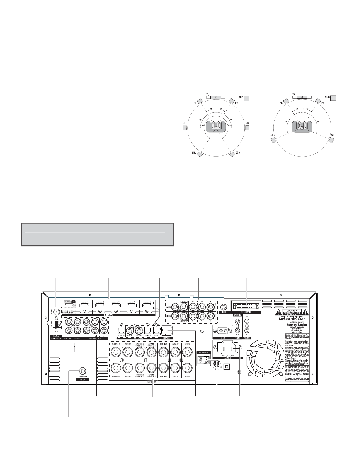
Place Your Speakers
Determi ne the locations f or your system’s speake rs according to thei r manufactur er’s direction s and
the layout of your listening room. Use the illustrations below as a guide for 7.1-channel and 5.1-channel
systems.
Speaker Positioning for
7.1-Channel Systems
For more detailed speaker placement information, including the use of front height speakers, download
the comple te AVR 3650, AVR 365, AVR 2650, AVR 265 Owner’s Manua l from www.harmankardon.com.
Speaker Positioning for
5.1-Channel Systems
Radio Antenna
Connectors
Subwoofer
Connector
2
HDMI®
Connectors
Analog Audio
Connectors
Digital Audio
Connectors
Speaker
Connectors
Rear-Panel Connection (AVR 3650 shown
ote: Silkscreening and connectors will vary for different models
Not all connectors shown will be present o n all models.
Analog Video
Connectors
Network
Connector
Main Power
Switch
The Bridge IIIP
Connector
AC Input
Connector
Page 3
AVR
Connections
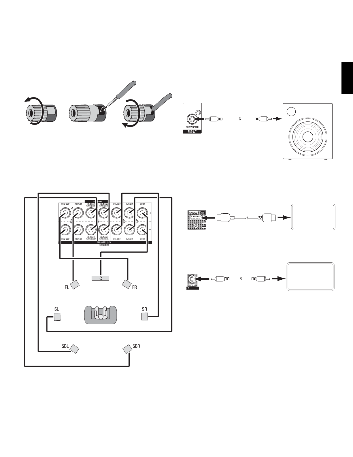
Connect Your Speakers
How to use the AVR spe aker terminals:
1. Unscrew C ap 2. Inser t Bare Wire
Always connect the colored (+) terminal on the AVR to the (+) terminal on the speaker (usually red),
and the black (–) terminal on the AVR to the (–) terminal on the speaker (usually black).
IMPORTANT: Make sure the (+) and (–) bare wires d o not touch each othe r or the other termina l.
Touching wire s can cause a shor t circuit that ca n damage your receiver o r amplifier.
Connect t he speakers as shown i n the illustration .
3. Tighten C ap
Connect Your Subwoofer
Use a single RC A audio cable to conne ct the receiver ’s Subwoofer Pre-O ut connector to yo ur subwoofer.
Consult your s ubwoofer’s user manu al for specific inf ormation about ma king connectio ns to it.
Receiver
Subwoofer
Connector
Single
RCA Audi o Cable
(not supplied)
Powered
Subwoofer
Connect Your TV or Video Display
If your TV h as an HDMI connect or: Use an HDMI cable (not inc luded) to connec t it to the receiver ’s
HDMI Monito r Out connector. You do not n eed to make any other conn ections to your T V from the
receiver or from any of your video source components.
Receiver
HDMI Moni tor Out
Connector
HDMI Cabl e
(not supplied)
TV
ENGLISH
If your TV d oes not have an HDMI conne ctor: Use a compo site video cable (not in cluded) to connec t
the receiv er’s Composite Monito r Out connector t o your TV’s composite v ideo connector.
Receiver
Composite
Monitor Out
Connector
Composi te Video
Cable
(not supplied)
Note: The HDMI c onnection to you r TV is preferre d. If you use the compo site video connec tion to your
TV, you will not be a ble to view the receiv er’s on-screen me nus.
TV
3
Page 4

AVR
I
Connect Your Audio and Video Source Devices
Connections
Source devices are components where a playback signal originates, e.g. a Blu-ray Disc™ or DVD player; a
cable, satellite or HDTV tuner; etc. Your receiver has several different types of input connectors for your
audio and vi deo source device s: HDMI, component vide o, composite video, op tical digital aud io, coaxial
digital audio and analog audio. The connectors are not labeled for specific types of source devices;
they are lab eled numericall y, so you can con nect your device s according to your in dividual syste m’s
make-up.
Your receiver ’s various source but tons have default as signments to diff erent input connec tors (listed
in the “Def ault Source But ton” column of the tab le below). For ease of setu p, you should connec t
each sour ce device to the connec tor where the cor responding def ault source but ton is assigned (e.g.,
connect your Blu-ray Disc player to HDMI 1).
AVR Input Connector Connected Component Default Source Button Assigned Source Button
HDMI 1 Blu-ray
HDMI 2 Cable/Sat
HDMI 3 Game
HDMI 4 Media Server
HDMI 5 TV
(AVR 3650, AVR 365 only) HDMI Front Aux
Component Video 1 A (red)
Component Video 2 B (green)
Composite Video 1 C (yellow)
Composite Video 2 D (green)
However, you can conn ect your source de vices as you wish and rea ssign any of the source b uttons to any
of the inpu t connectors li sted in the table acc ording to where you ac tually connec t each of your source
devices.
As you conne ct your various s ource component s, fill out the “Connect ed Component” co lumn in the
table – it wi ll make it easier for you to a ssign the various s ource buttons af ter you have complete d
making all o f the connectio ns. (You will make any change s to the source-bu tton assignmen ts and fill in
the “Assigne d Source Button” c olumn later in the set up process.)
Optical Digital Audio 1 A (red)
Optical Digital Audio 2 B (green)
Coaxial Digital Audio Input 1 C (yellow)
Coaxial Digital Audio Input 2
Analog Audio In 1 D (green)
Analog Audio In 2
Analog Audio In 3
Monitor Output Connector Connected Component
HDMI Monitor Out
Composite Video Monitor Out
Record Output Connector Connected Component
Composite Video Rec Out
Optical Digital Audio Out
nput Connections and Assigned Source Buttons
4
Page 5

AVR
Connections
HDMI Devices
If any of your so urce devices have HDMI con nectors, usin g them will provide t he best possible v ideo and
audio per formance quali ty. Since the HDMI cable c arries both dig ital video and digi tal audio signals,
you do not have to ma ke any additional audi o connections f or source devices you c onnect via HDMI
connectors.
Note: If you have a T V or other source dev ice equipped with t he HDMI Audio Return Ch annel Function,
you can fee d its sound to the AVR via t he HDMI Monitor Out co nnection’s Audio Ret urn Channel, and it
will not req uire additional a udio connectio ns to the AVR. Refer to the co mplete AVR 3650, AVR 365, AVR
2650, AVR 265 Owner’s Manua l, downloadable at www.harmankardon.com.
Receiver
HDMI Connectors
HDMI Cabl e
(not supplied)
To HDM I
Output
HDMI-Equipped
Source Device
Composite Video Devices
Use composi te video connec tors for video so urce devices that don’t h ave HDMI or component vid eo
connec tors. You will also nee d to make an audio connec tion from the so urce device to the rece iver.
Receiver
Video Connectors
Composi te Video Cabl e
(not supplied)
To Composit e
Video Output
Composite Video-Equipped
Source Device
Optica l digital audio d evices
If your non- HDMI source device s have optical digit al outputs, conne ct them to the rece iver’s optical
digital au dio connector s. NOTE: Make only one t ype of digital conn ection (HDMI, opti cal or coaxial)
from each device.
Receive r Digital Audi o
Connectors
ENGLISH
Component Video Devices
If any of your vi deo source device s have component video c onnectors (and do n ot have HDMI
connec tors), using the compon ent video connec tors will provi de superior vide o performance. You
will also ne ed to make an audio conne ction from the s ource device to the re ceiver.
Receiver Video
Connectors
Compone nt Video Cabl e
(not supplied)
To Component
Video Outputs
Component Video-Equipped
Source Device
Optica l Digital Audi o
Cable (not supplied)
To Optical D igital Audio
Output
Optical-Equipped
Source Device
Coaxia l digital audio de vices
If your non- HDMI source device s have coaxial digita l outputs, conne ct them to the recei ver’s coaxial
digital au dio connector s. NOTE: Make only one t ype of digital conn ection (HDMI, opti cal or coaxial)
from each device.
Receive r Digital Audi o
Connectors
Coaxial D igital Audio
Cable (not supplied)
To Coaxial Di gital
Audio Output
Coaxial-Equipped
Source Device
5
Page 6

AVR
Connections
Analog Audio Devices
Use the receiver’s analog audio connectors for source devices that don’t have HDMI or digital audio
connectors.
Receiver
Analog Audio Connectors
Stereo Audi o
Cable (not supplied)
To Stereo Analo g Audio
Output
Analog
Source Device
Audio Reco rders
Connec t a digital audio reco rder’s optical dig ital input to the re ceiver’s optical dig ital output. You can
record bo th coaxial and opti cal digital inpu t signals
Receiver
Digita l Audio Record er Connecto r
Connect an analog audio recorder’s inputs to the receiver’s analog audio Rec Out connectors. You can
record any analog audio input signal.
Receiver
Analog Audio Recorder Connectors
Stereo Audi o
Cable (not supplied)
To Stereo Analo g Record
Inputs
Analog
Recording Device
Video Recorders
Connect an analog video recorder’s video input connector to the receiver’s composite video Rec Out
connec tor. You can reco rd any composite vid eo signal. NOTE: To record t he audio and video f rom the
source device, connect the receiver’s analog audio Rec Out connectors to the analog video recorder’s
audio inpu ts.
Receive r Analog Video
Recorder Connectors
Receive r Analog Audio
Recorder Connectors
Optica l Digital Audi o
Cable (not supplied)
To Optical D igital
Record Input
Digital
Recording Device
Analog Audio/
Video Ca ble
(not supplied)
Analog Vi deo Recordi ng
Device
To Analog
Audio/Video
Record Inputs
.
6
Page 7

AVR
Connections
Connect The Bridge IIIP
Connect an optional The Bridge IIIP to the receiver’s The Bridge IIIP connector. Insert the plug all the
way until it sn aps into place in the con nector. IMPORTANT: Connec t The Bridge IIIP only with the
receiver’s power turned OFF.
Receiver
The Bridge IIIP
Connector
The Bridge IIIP
Connect Your Local Area Network
Use a Cat. 5 or C at. 5E cable (not supplie d) to connect the re ceiver’s Network c onnector to your ho me
networ k to enjoy Internet ra dio and content fro m DLNA®-compat ible devices that ar e connected to th e
network.
Receiver
Network
Connector
Network
Modem
Connect the Radio Antennas
Connec t the supplied FM antenn a to the receiver’s FM 75Ω antenn a connector. For the be st t
recepti on, extend the FM ante nna as far as possible.
Bend and fo ld the base of the sup plied AM antenna as sho wn and connect the a ntenna wires to the t
receiver ’s AM and Gnd connect ors. (You can connec t either wire to ei ther connector.) Rota te the
antenna as necessary to minimize background noise.
Receiver
Antenna
Connectors
FM Antenna
(supplied)
AM
Antenna
(supplied)
Bend and fold base
NOTE: To connect an optional SIRIUS Connect™ home tuner (AVR 3650 and AVR 2650 only), RS-232,
multi-zone, remote IR and trigger equipment, please download the AVR 3650, AVR 365, AVR 2650, AVR
265 Owner’s Manual from www.harmankardon.com.
Connect to AC Power
Connect t he AC power cord to the rece iver’s AC Input connec tor and then to a workin g,
non-switched AC power outlet.
Receiver
AC Input
Connector
AC Power
Outlet
ENGLISH
To
Cat. 5/5E Cable
(not supplied)
Internet
and LAN
Power Cord
(supplied)
7
Page 8

AVR
Connections
Set Up the Receiver
Install t he Batteries in t he Remote Control
Remove the re mote control’s bat tery cover, inser t the four suppl ied AAA bat teries as shown in t he illustrati on,
and replace t he battery co ver.
NOTE: Remove t he protective pl astic from the re ceiver’s front pane l so it doesn’t reduc e the remote
control’s effectiveness.
Turn On the Rece iver
Set the rear-p anel Main Power switch to “O n.” (The fro nt-panel Power indicato r will glow amber.)1.
Press the f ront-panel Power but ton.2.
Main Power
Switch
Power
Button
Place the microphone at ear height in your listening position.2.
Turn on your TV a nd select the T V input where you conn ected the recei ver in 3.
page 3.
Press the r emote control’s Set up button. The rec eiver’s on-scree n display (OSD) setup menu will 4.
appear on th e TV. (Note: If you have used a comp osite video connec tion to your TV, the OSD men us
will not app ear on your TV. Follow the st eps below using the re ceiver’s front-pa nel display.)
Connect Your T V, o n
Source Select
Select the Source Device to Enjoy
Setup Source
Setup Source Devices Connected to the AVR
Speaker Setup
Speaker Optimization, EQ
Zone 2
Manage and Control Zone 2
System
General AVR Settings
Use the remo te’s arrow and OK button s to select “Speake r Setup.”5.
Speaker Setup
Configure Your Speakers
Plug the sup plied EzSet /EQ™ microphone in to the receiver’s Head phone connecto r.1.
EzSet Microphone
(supplied)
Receiver
Headphone
Connector
Automatic Setup – EzSet/EQ
Automated Speaker Setup and EQ
Manual Setup
Manually Adjust Speaker Settings
Select “Automatic Setup – EzSet/EQ.”6.
Select “Continue.”7.
Follow the i nstruction s that appear on the sc reens.8.
Assign The Receiver’s Source Buttons
Review the i nput connecti ons you listed on the1.
page 4. Note what chang es (if any) you want to make fro m the default sour ce-button as signments
on
that appear on the list.
Turn on your TV a nd select the T V input where you conn ected the recei ver in2. Connect Your TV, on
page 3.
Input Connectio ns and Assigned Source Buttons table,
8
Page 9

AVR
Connections
Press the r emote control’s Setu p button. The rec eiver’s on-scree n display (OSD) setup menu will 3.
appear on th e TV. (Note: If you have used a comp osite video connec tion to your TV, the OSD men us
will not app ear on your TV. Follow the st eps below using the re ceiver’s front-pa nel display.)
Source Select
Select the Source Device to Enjoy
Setup Source
Setup Source Devices Connected to the AVR
Speaker Setup
Speaker Optimization, EQ
Zone 2
Manage and Control Zone 2
System
General AVR Settings
Use the remo te’s arrow and OK butto ns to select “Set up Source,” and selec t a source button t hat you 4.
want to re- assign from the lis t that appears. Pr ess the OK button .
Source Select
Select the Source Device to Enjoy
Setup Source
Setup Source Devices Connected to the AVR
Speaker Setup
Speaker Optimization, EQ
Zone 2
Manage and Control Zone 2
System
General AVR Settings
Cable/Sat
Blu-ray
Bridge
USB
SIRIUS Radio
FM Radio
AM Radio
TV
Game
Media Server
Cable/
Sat
Press the r emote control’s Set up button again. Th e receiver’s on-sc reen display (OSD) setup men u 6.
will reapp ear on the TV. (Note: If you have use d a composite video c onnection to you r TV, the OSD
menus will n ot appear on your TV. Follow t he steps below usin g the receiver’s fro nt-panel display.)
Use the remo te’s arrow and OK butto ns to select “Set up Source,” and selec t the source butt on whose 7.
video inp ut you just re-ass igned.
Selec t “Audio Input f rom Source” and se lect the audio in put connector yo u want to assign to the 8.
source bu tton. Press the OK b utton.
Cable/Sat
Audio Effects
Video Modes:
Surround Modes:
Audio Format from Source:
Video Input from Source:
Audio Input from Source:
Resolution to Display:
Resolution from Source:
HDMI Bypass:
Change Name:
Adjust Lip Sync
Off
Auto Select
NO AUDIO INPUT
Component 1
Analog 1
720p – 60Hz
No Input
Off
Cable/Sat
HDMI 1
HDMI 2
HDMI 3
HDMI 4
HDMI 5
HDMI Front
Optical 1
Optical 2
Coaxial 1
Coaxial 2
Analog 1
Press the r emote’s Back/E xit button and re peat steps 3 – 8 for the re maining source bu ttons you 9.
want to reassign.
You are now read y to enjoy your rece iver!
IMPORTANT: For complete i nformation abo ut using all of your aud io/video recei ver’s features
and capabilities, download the AVR 3650, AVR 365, AVR 2650, AVR 265 Owner’s Manual from
www.harmankardon.com.
General Specifications
ENGLISH
Selec t “Video Input From S ource” and selec t the video input c onnector you wan t to assign to the 5.
source bu tton. Press the OK b utton. (The se tup menu will disap pear from the TV.)
Cable/Sat
Audio Effects
Video Modes:
Surround Modes:
Audio Format from Source:
Video Input from Source:
Audio Input from Source:
Resolution to Display:
Resolution from Source:
HDMI Bypass:
Change Name:
Adjust Lip Sync
Off
Auto Select
NO AUDIO INPUT
HDMI 2
HDMI 2
720p – 60Hz
No Input
Off
Cable/Sat
HDMI 1
HDMI 2
HDMI 3
HDMI 4
HDMI 5
HDMI Front
Component 1
Component 2
Composite 1
Composite 2
Power consumption
(AVR 3650): <0.5W (standby); 480W (maximum)
(AVR 365): <0.5W (standby); 480W (maximum)
(AVR 2650/AVR 265): <0.5W (standby); 420W (maximum)
Dimensio ns (W x H x D): 17-5/16" x 6-1/2" x 17-1/16"
(440mm x 165mm x 435mm)
Weight
(AVR 3650/AVR 365): 27.25 lb (12.4kg)
(AVR 2650/AVR 265): 24.4 lb (11.1kg)
9
Page 10

HARMAN Consumer, Inc.
8500 Balboa Boulevard, Northridge, CA 91329 USA
516.255.4545 (USA onl y)
Made in P.R.C.
© 2011 HARMAN Inter national Ind ustries, In corporate d. All rights re served.
harman ka rdon is a trade mark of HARMAN In ternational I ndustrie s, Incorpora ted, registe red in the Unite d States and/or oth er countrie s. EzSet/ EQ is a
tradem ark of HARMAN Int ernational I ndustries , incorporat ed. DLNA is a regi stered trad emark of the Dig ital Living N etwork Alli ance. HDMI, the HDMI l ogo
and High- Definition M ultimedia In terface are t rademark s or register ed trademark s of HDMI Licens ing LLC in the Unite d States and other countries. SIRIUS,
SIRIUS Conne ct and all rela ted marks and l ogos are trad emarks of SIRI US XM Radio inc., an d its subsidia ries.
Features, specifications and appearance are subject to change without notice.
www.harmankardon.com
 Loading...