

Page 1

harman/kardon
AVR 2650
7 X 95W 7.1 CHANNEL A/V RECEIVER
SERVICE MANUAL
CONTENTS
ESD W A R N I NG…………………......……….2
LEAKAGE TESTING……………….…..…....3
BASIC SPECIFICATIONS…………………..4
PACKAGING…………………………….……5
FRON T P A NEL CO N T R OLS………..…..…..6
REAR PANEL CONNECTIONS………….…8
REMOTE CONTROL FUNCTIONS……….10
CONNECTIONS/INSTALLATION………....12
OPERATION………………………....………19
TROUBLESHOOTING GUIDE….......…..…24
REMOTE & PROCESSOR RESETS….......25
harman/kardon, Inc.
Released 2011 8500 Balboa Blvd..
Discontinued XXXX Northridge, CA. 91329 Rev1 9/2011
DISASSEMBLY…...……….………..………..26
UNIT E XPLOD E D V IEW…………..…….…..27
EXPL ODED V I E W P A RTS LI S T ……………28
AMP BIAS ADJUSTMENT……….……….…29
BLOCK DIAGRAM………………….………..30
PCB DRAWINGS…………………….………32
ELECTRICAL PARTS LIST…………….……47
SEMICONDUCTOR PINOUTS……..…..…103
SCHEMATICS……………………………….224
WIRING DIAGRAM ………………………….241
Page 2

AVR 2650 harman/kardon
2
Some semiconductor (solid state) devices can be damaged easily by static electricity. Such components commonly are called
Electrostatically Sensitive (ES) Devices. Examples of typical ES devices are integrated circuits and some field effect transistors and
semiconductor "chip" components.
The following techniques should be used to help reduce the incidence of component damage caused by static electricity.
1. Immediately before handling any semiconductor component or semiconductor-equipped assembly, drain off any electrostatic charge on
your body by touching a known earth ground. Alternatively, obtain and wear a commercially available discharging wrist strap device,
which should be removed for potential shock reasons prior to applying power to the unit under test.
2. After removing an electrical assembly equipped with ES devices, place the assembly on a conductive surface such as aluminum foil, to
prevent electrostatic charge build-up or exposure of the assembly.
3. Use only a grounded-tip soldering iron to solder or unsolder ES devices.
4. Use only an anti-static solder removal device. Some solder removal devices not classified as "anti-static" can generate electrical charges
sufficient to damage ES devices.
5. Do not use freon-propelled chemicals. These can generate electrical change sufficient to damage ES devices.
6. Do not remove a replacement ES device from its protective package until immediately before you are ready to install it. (Most replacement
ES devices are packaged with leads electrically shorted together by conductive foam, aluminum foil or comparable conductive material.)
7. Immediately before removing the protective material from the leads of a replacement ES device, touch the protective material to the
chassis or circuit assembly into which the device will be installed.
CAUTION :
8. Minimize bodily motions when handling unpackaged replacement ES devices. (Otherwise harmless motion such as the brushing together
or your clothes fabric or the lifting of your foot from a carpeted floor can generate static electricity sufficient to damage an ES devices.
Be sure no power is applied to the chassis or circuit, and observe all other safety precautions.
Each precaution in this manual should be followed during servicing.
Components identified with the IEC symbol in the parts list are special significance to safety. When replacing a component identified with
, use only the replacement parts designated, or parts with the same ratings or resistance, wattage, or voltage that are designated in the
parts list in this manual. Leakage-current or resistance measurements must be made to determine that exposed parts are acceptably
insulated from the supply circuit before retuming the product to the customer.
Page 3
SAFETY PRECAUTIONS
The following check should be performed for the continued
protection of the customer and service technician.
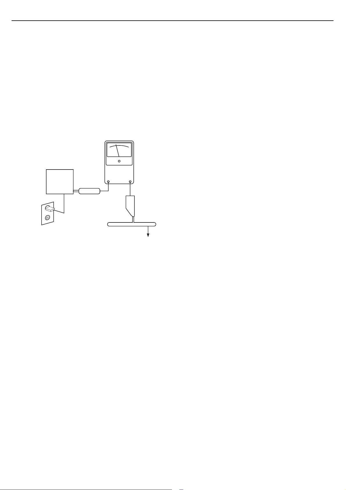
LEAKAGE CURRENT CHECK
Measure leakage current to a known earth ground (water
pipe, conduit, etc.) by connecting a leakage current tester
between the earth ground and all exposed metal parts of the
appliance (input/output terminals, screwheads, metal
overlays, control shaft, etc.). Plug the AC line cord of the
appliance directly into a 120V AC 60Hz outlet and turn the
AC power switch on. Any current measured must not exceed
o.5mA.
ANY MEASUREMENTS NOT WITHIN THE LIMITS
OUTLINED ABOVE ARE INDICATIVE OF A
POTENTIAL SHOCK HAZARD AND MUST BE
CORRECTED BEFORE RETURNING THE APPLIANCE
TO THE CUSTOMER.
AVR 2650 harman/kardon
3
Reading should
not be above
0.5mA
Device
under
test
Leakage
current
tester
Test all
exposed metal
surfaces
Also test with
plug reversed
(Using AC adapter
plug as required)
Earth
ground
AC Leakage Test
Page 4
AVR 2650 harman/kardon
4
AVR
Specifications
Audio Section
Stereo power: AVR 3650/AVR 365: 110W per channel, two channels
Multichannel power: AVR 3650/AVR 365: 110W per channel, two channels
Input sensitivity/impedance: 200mV/47k ohms
Signal-to-noise ratio (IHF-A): 100dB
Surround system adjacent
channel separation:
Frequency response (@ 1W): 10Hz – 130kHz (+0dB/–3dB)
High instantaneous current
capability (HCC):
Transient intermodulation
distortion (TIM):
Slew rate: 40V/μsec
driven @ 8 ohms, 20Hz – 20kHz, <0.09% THD
AVR 2650/AVR 265: 95W per channel, two channels
driven @ 8 ohms, 20Hz – 20kHz, <0.09% THD
driven @ 8 ohms, 20Hz – 20kHz, <0.09% THD
AVR 2650/AVR 265: 95W per channel, two channels
driven @ 8 ohms, 20Hz – 20kHz, <0.09% THD
Dolby Pro Logic/DPLII: 40dB
Dolby Digital: 55dB
DTS: 55dB
±35 amps
Unmeasurable
Specifications
Video Section
Television format: NTSC (AVR 3650/AVR 2650);
Input level/impedance: 1Vp-p/75 ohms
Output level/impedance: 1Vp-p/75 ohms
Video frequency response
(composite video):
HDMI: Version 1.4a with 12-bit Deep Color
General Specifications
Power requirement: 120V AC/60Hz (AVR 3650/AVR 2650);
Power consumption:
Dimensions (W x H x D):
Weight
PAL (AVR 365/AVR 265)
10Hz – 8MHz (–3dB)
220V – 240V AC/50Hz – 60Hz (AVR 365/AVR 265)
<0.5W (standby);
480W maximum (AVR 3650/AVR 365);
420W maximum (AVR 2650/AVR 265)
17-5/16" x 6-1/2" x 17-1/8"
(440mm x 165mm x 435mm)
(AVR 3650/AVR 365): 27.25 lb (12.4kg)
(AVR 2650/AVR 265): 24.4 lb (11.1kg)
FM Tuner Section
Frequency range: 87.5 – 108.0MHz
Usable sensitivity IHF: 1.3μV/13.2dBf
Signal-to-noise ratio (mono/stereo): 70dB/68dB
Distortion (mono/stereo): 0.2%/0.3%
Stereo separation: 40dB @ 1kHz
Selectivity (±400kHz): 70dB
Image rejection: 80dB
IF rejection: 90dB
AM Tuner Section
Frequency range: 520 – 1710kHz (AVR 3650/AVR 2650)
522 – 1620kHz (AVR 365/AVR 265)
Signal-to-noise ratio: 45dB
Usable sensitivity (loop):
Distortion (1kHz, 50% mod): 0.8%
Selectivity (±10kHz): 30dB
500μV
Depth measurement includes knobs, buttons and terminal connections.
Height measurement includes feet and chassis.
Page 5
AVR 2650 harman/kardon
5
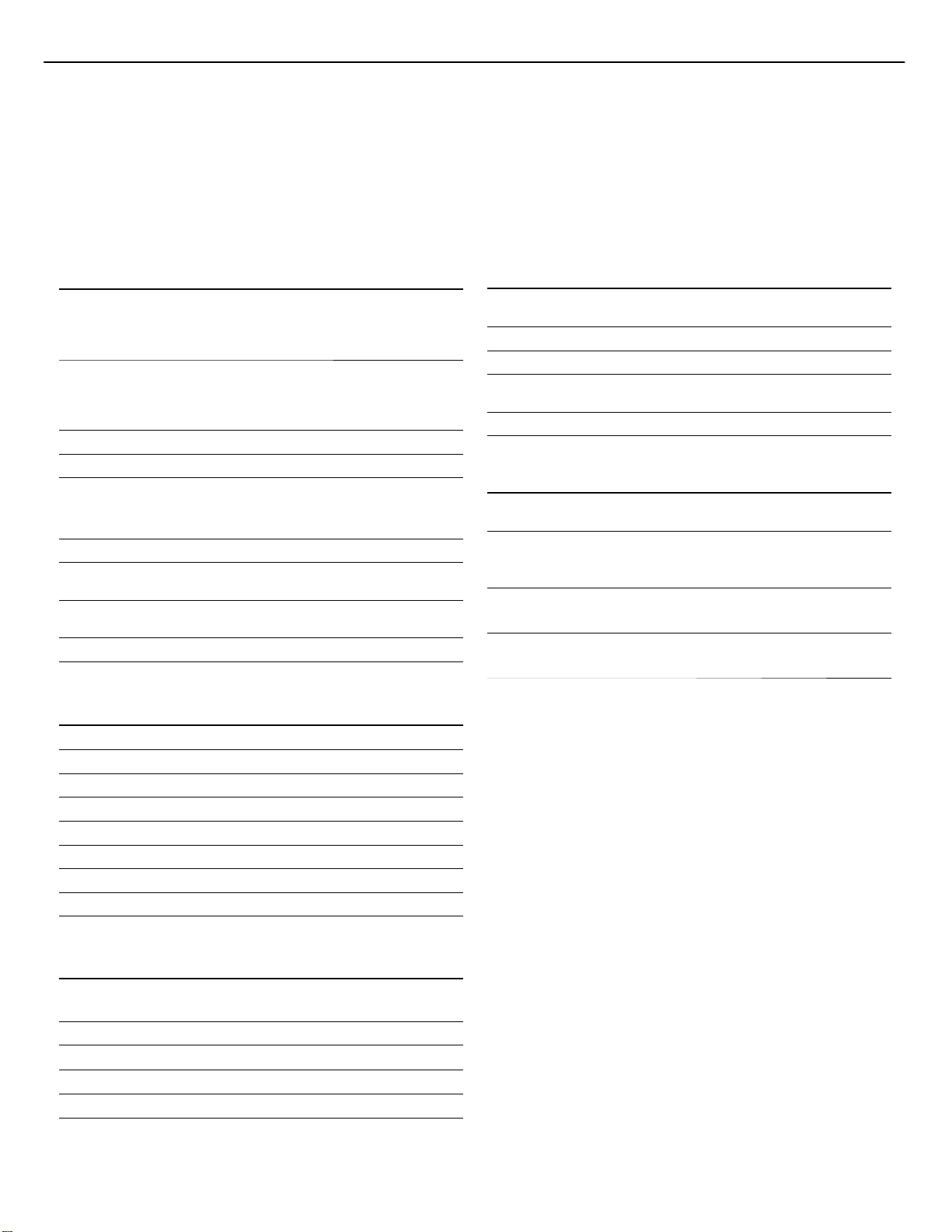
AVR 2650
OUTER CARTON
FOAM PAD (L)
FOAM PAD (R)
AVR 2650
OUTER CARTON
Page 6
ge
AVR 2650 harman/kardon
6
AVR
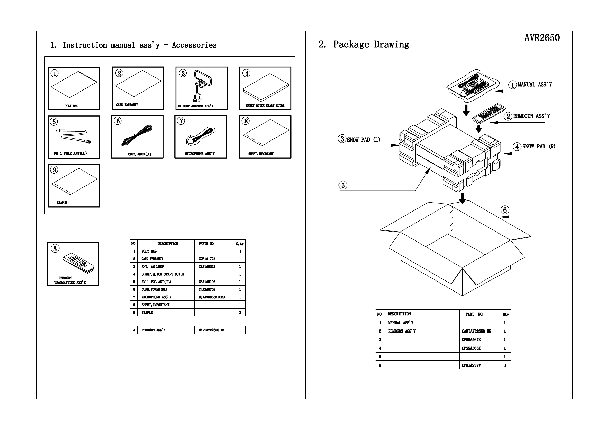
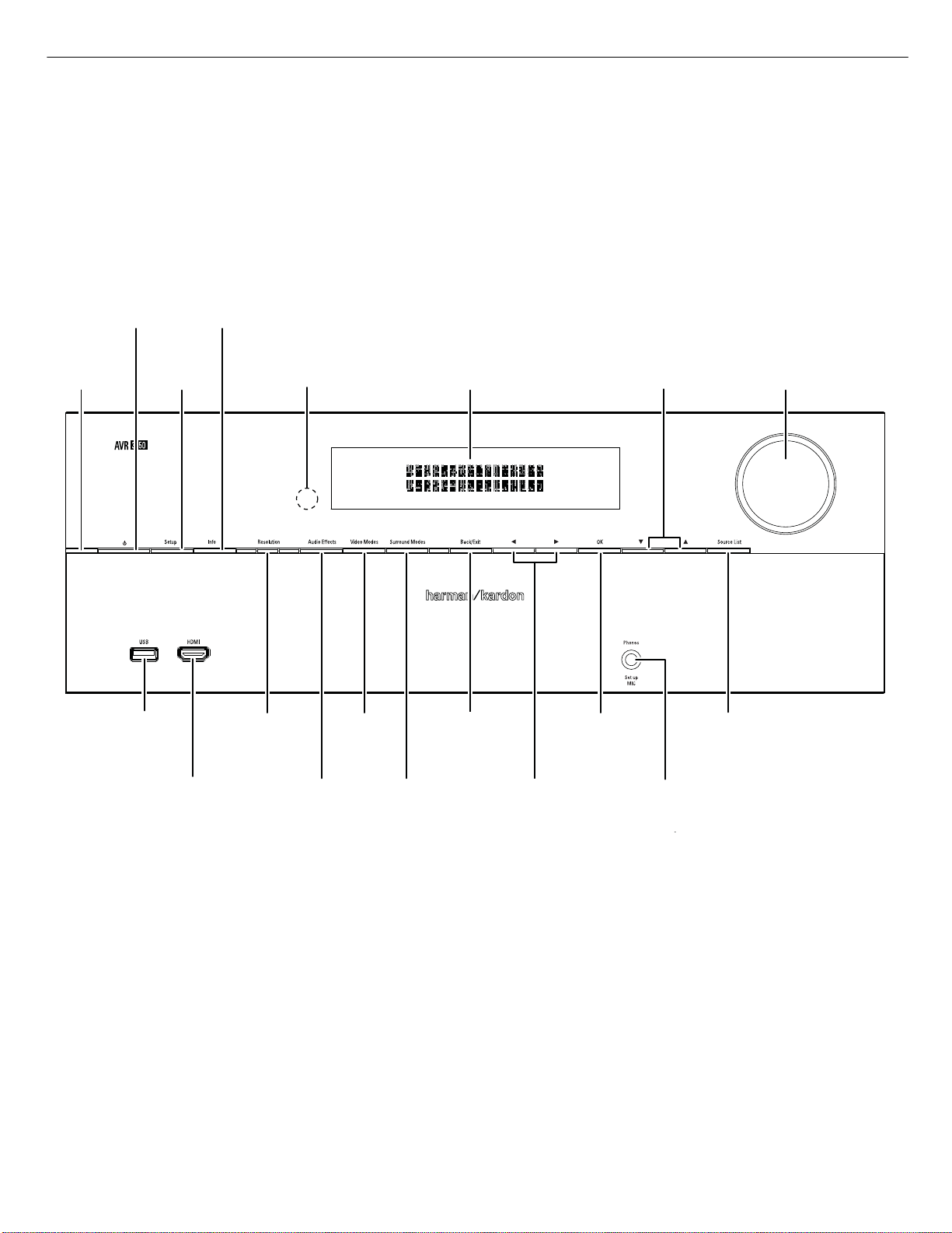
Front-Panel Controls
Power
Power
Button
Button
Power
Power
Indicator
Indicator
Setup
Setup
Button
Button
Info
Info
Button
Button
IR
IR
Sensor
Sensor
Message
Message
Display
Display
Up/Down
Up/Down
Buttons
Buttons
Front-Panel Controls
Volume
Volume
Knob
Knob
USB
USB
Port
Port
®
HDMI® Front
HDMI
Input Connector
Input Connector
Front
Resolution
Resolution
Button
Button
Audio
Audio
Effects
Effects
Button
Button
Video
Video
Modes
Modes
Button
Button
Surround
Surround
Modes
Modes
Button
Button
Back/Exit
Back/Exit
Button
Button
Left/Right
Left/Right
Buttons
Buttons
OK
OK
Button
Button
Headphone Jack/
Headphone Jack/
EzSet/EQ
EzSet/EQ
Mic Input
Mic Input
Source List
Source List
Button
Button
ontinued on next pa
Page 7

AVR 2650 harman/kardon
7
AVR
Front-Panel Controls, continued
Power Indicator: This LED has three possible modes:
• LED is off: Indicates that the AVR is unplugged or the rear-panel Main Power switch
is off.
• LED glows amber: Indicates that the AVR is in the Standby mode.
• LED glows white: Indicates that the AVR is turned on.
IMPORTANT NOTE: If the PROTECT message ever appears on the AVR’s frontpanel message display, turn off the AVR and unplug it from the AC outlet.
Check all speaker wires for a possible short-circuit (the “+” and “–” conductors
touching each other or both touching the same piece of metal). If a short-circuit
is not found, bring the unit to an authorized Harman Kardon service center for
inspection and repair before using it again.
Power button: Press this button to turn the receiver on or to place it in the Standby
mode.
Setup button: Press this button to access the AVR’s main menu.
Info button: Press this button to access the AVR’s Source submenu, which contains
the settings for the source currently playing. Use the Up/Down buttons to scroll
through the different settings.
Message display: Various messages appear in this two-line display in response
to commands and changes in the incoming signal. In normal operation, the current
source name appears on the upper line, while the surround mode is displayed on
the lower line. When the on-screen display menu system (OSD) is in use, the current
menu settings appear.
IR sensor: This sensor receives infrared (IR) commands from the remote control.
It is important to ensure that the sensor is not blocked. AVR 3650/AVR 365 only:
If covering the IR sensor is unavoidable (such as when the receiver is installed inside
of a cabinet), connect an optional infrared receiver to the Remote IR In connector on
the AVR’s rear panel.
Up/Down buttons: Use these buttons to navigate the AVR’s menus.
Volume knob: Turn this knob to raise or lower the volume.
USB port: You can use this port to perform software upgrades that may be offered in
the future. Do not connect a storage device, peripheral product or a PC here, unless
you are instructed to do so as part of an upgrade procedure.
HDMI (High-Definition Multimedia Interface
an HDMI-capable source component that will be used only temporarily, such as a
camcorder or game console, here.
®
) Front Input connector: Connect
Front-Panel Controls, continued
Resolution button: Press this button to access the AVR’s video output resolution
setting: 480i, 480p, 720p, 1080i, 1080p or 1080p/24Hz. Use the Up/Down and OK
buttons to change the setting.
IMPORTANT NOTE: If you set the AVR’s video output resolution higher than
the capabilities of the actual connection between the AVR and your TV or
video display, you will not see a picture. If you are using the composite video
connection from the AVR to your TV (see Connect Your TV or Video Display, on
page 17), press the Resolution button and use the Up/Down and OK buttons to
change the resolution to 480i.
Audio Effects button: Press this button to access the Audio Effects submenu,
which allows you to adjust the AVR’s tone controls and other audio controls. See Set
Up Your Sources, on page 26, for more information.
Video Modes button: Press this button for direct access to the Video Modes
submenu, which contains settings you can use to improve the video picture. Use
the OK button to scroll through the different modes, and use the Up/Down and Left/
Right buttons to make adjustments within each mode. See Set Up Your Sources, on
page 26, for more information.
Surround Modes button: Press this button to select a listening mode. The Surround
Modes menu will appear on screen, and the menu line will appear in the front-panel
display. Use the Up/Down buttons to change the surround-mode category and the
Left/Right buttons to change the surround mode for that category. See Set Up Your
Sources, on page 26, for more information.
Back/Exit button: Press this button to return to the previous menu or to exit the
menu system.
Left/Right buttons: Use these buttons to navigate the AVR’s menus.
OK button: Press this button to select the currently highlighted item.
Headphone jack/EzSet/EQ Mic input: Connect a 1/4" stereo headphone plug
to this jack for private listening. This jack is also used to connect the supplied
microphone for the EzSet/EQ procedure described in Configure the AVR For Your
Speakers, on page 25.
Source List button: Press this button to select a source device to watch/listen to.
Use the Up/Down buttons to scroll through the source-device list, and press the OK
button to select the source being displayed.
Page 8
)
e
AVR 2650 harman/kardon
8
AVR
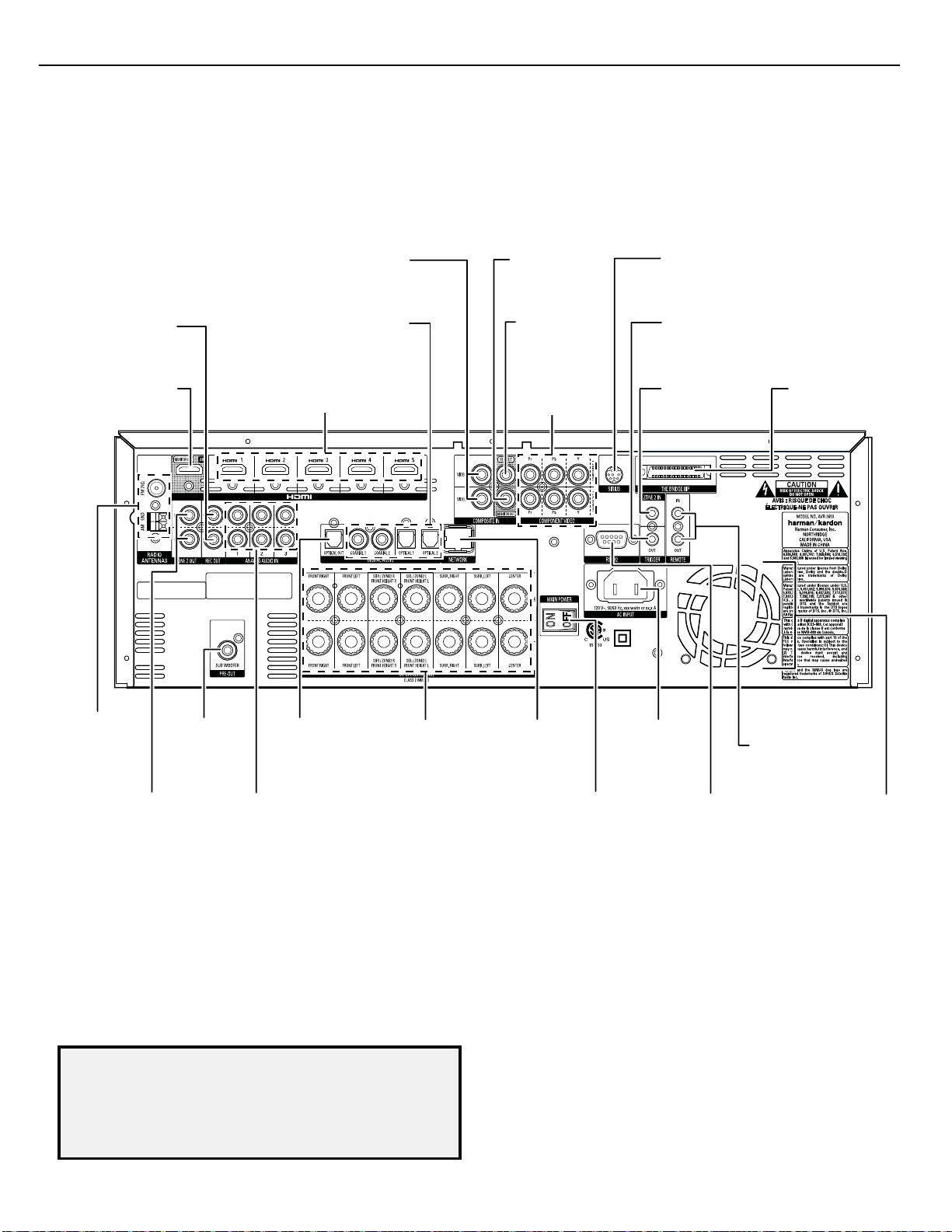
Rear-Panel Connectors
Analog
Analog
Record Out
Record Out
Connector
Connector
HDMI
HDMI
Monitor Out
Monitor Out
Connector
Connector
Composite
Composite
Video Input
Video Input
Connectors
Connectors
Digital Audio
Digital Audio
Input Connectors
Input Connectors
Input
HDMI
HDMI Input
Connectors
Connectors
Composite
Composite
Video Monitor
Video Monitor
Out Connector
Out Connector
Composite
Composite
Video Record
Video Record
Out Connector
Out Connector
Component
Composite
Video Input
Video Input
Connectors
Connectors
Rear-Panel Connectors
®
SIRIUS® Tuner
SIRIUS
Tuner
Connector
Connector
(AVR 3650/AVR 2650)
(AVR 3650/AVR 2650)
12V
12V
Trigger
Trigger
Connector
Connector
Zone 2 IR In
Zone 2 IR In
Connector
Connector
(AVR 3650/AVR365)
(AVR 3650/AVR 365)
The Bridge IIIP
The Bridge IIIP
Connector
Connector
Radio Antenna
Radio Antenna
Connectors
Connectors
Zone 2 Out
Zone 2 Out
Connector
Analog Record Out connector: Connect this analog audio output to the analog
audio input of a recording device. A signal is available at this output whenever an
analog audio source is playing.
HDMI Monitor Out connector: If your TV has an HDMI connector, use an HDMI
cable (not included) to connect it to the AVR’s HDMI Monitor Out connector. The
AVR will automatically transcode component and composite video input signals to
the HDMI format (upscaling to as high as 1080p), so you do not need to make any
other connections to your TV from the AVR or from any of your video source devices.
Notes on using the HDMI Monitor Out connector:
• When connecting a DVI-equipped display to the HDMI Monitor Out connector,
use an HDMI-to-DVI adapter and make a separate audio connection.
• Make sure the HDMI-equipped display is HDCP (High-bandwidth Digital Content
Protection)-compliant. If it isn’t, do not connect it via an HDMI connection; use an
analog video connection instead and make a separate audio connection.
Connector
Subwoofer
Subwoofer
Connector
Connector
Input Connectors
Input Connectors
Analog Audio
Analog Audio
Optical
Optical
Digital Output
Digital Output
Connector
Connector
Speaker
Speaker
Connectors
Connectors
ear-Panel Connectors (AVR 3650 shown
Network
Network
Connector
Connector
Main Power
Main Power
Switch
Switch
HDMI Input connectors: An HDMI connection transmits digital audio and video
signals between devices. If your source devices have HDMI connectors, using them
will provide the best possible video and audio performance quality. Since the HDMI
cable carries both digital video and digital audio signals, you do not have to make
any additional audio connections for devices you connect via the HDMI connection.
See Connect Your Audio and Video Source Devices, on page 18, for more information.
Composite Video Input connectors: Use composite video connectors for video
source devices that don’t have HDMI or component video connectors. You will also
need to make an audio connection from the source device to the AVR. See Connect
Your Audio and Video Source Devices, on page 18, for more information.
Digital Audio Input connectors: If your non-HDMI source devices have digital
outputs, connect them to the AVR’s digital audio connectors. NOTE: Make only one
type of digital connection (HDMI, optical or coaxial) from each device. See Connect
Your Audio and Video Source Devices, on page 18, for more information.
AC Input
AC Input
Connector
Connector
RS-232
RS-232
Connector
Connector
IR Remote
IR Remote
In/Out Connectors
In/Out Connectors
(AVR 3650/AVR 365)
(AVR 3650/AVR365)
ontinued on next pag
Fan
Vents
Vents
Fan
Page 9

AVR 2650 harman/kardon
9
AVR
Rear-Panel Connectors, continued
Composite Video Monitor Out connector: If your TV or video display does not
have an HDMI connector, use a composite video cable (not included) to connect the
AVR’s Composite Video Monitor Out connector to your TV’s composite video input.
NOTE: The HDMI connection to your TV is preferred. If you use the composite video
connection to your TV, you will not be able to view the AVR’s on-screen menus.
Composite Video Record Out connector: Connect an analog video recorder’s video
input connector to the AVR’s Composite Video Rec Out connector. You can record
any composite video input signal. NOTE: To record the audio and video from the
source device, connect the AVR’s Analog Record Output connectors to the analog
video recorder’s audio inputs.
Component Video Input connectors: If any of your video source devices have
component video connectors (and do not have HDMI connectors), using the
component video connectors will provide superior video performance. You will also
need to make an audio connection from the device to the receiver. See Connect Your
Audio and Video Source Devices, on page 18, for more information.
®
SIRIUS
Tuner connector: Connect a SIRIUSConnect™ satellite radio tuner module
here. (Not included. Available at www.sirius.com.) See Connect Your Audio and Video
Source Devices, on page 18, for more information.
12V Trigger connector: This connector provides 12V DC whenever the AVR is on.
It can be used to turn on and off other devices such as a powered subwoofer.
Zone 2 IR Input connector (AVR 3650/AVR 365 only): Connect a remote IR receiver
located in Zone 2 of a multizone system to this jack to control the AVR (and any
source devices connected to the Remote IR Output connector) from the remote zone.
The Bridge IIIP connector: Connect an optional Harman Kardon The Bridge IIIP
docking station to this input. Insert the plug until it snaps into place in the connector.
IMPORTANT: Connect The Bridge IIIP only with the AVR’s power turned off.
Radio Antenna connectors: Connect the included AM and FM antennas to their
respective terminals for radio reception.
Zone 2 Out connectors: Connect these jacks to an external amplifier to power the
speakers in the remote zone of a multizone system.
Subwoofer connector: Connect this jack to a powered subwoofer with a line-level
input. See Connect Your Subwoofer, on page 17, for more information.
Analog Audio Input connectors: Use the AVR’s Analog Audio Input connectors for
source devices that don’t have HDMI or digital audio connectors. See Connect Your
Audio and Video Source Devices, on page 18, for more information.
Optical Digital Output connector: Connect a digital audio recorder’s optical digital
input to the AVR’s Optical Digital Output connector. You can record both coaxial and
optical digital audio signals.
Rear-Panel Connectors, continued
Speaker connectors: Use two-conductor speaker wire to connect each set of
terminals to the correct speaker. See Connect Your Speakers, on page 17, for more
information.
NOTE: The speaker connectors, also called Assigned Amp speaker connectorsare used for the surround back channels in a 7.1- channel home theater, or you
can reassign them to a remote room for multizone operation or to front height
channels for Dolby Pro Logic® IIz operation. See Place Your Speakers, on page
13, for more information.
Network connector: Use a Cat. 5 or Cat. 5E cable (not supplied) to connect the AVR’s
Network connector to your home network to enjoy Internet radio and content from
DLNA®-compatible devices that are connected to the network. See Connect to Your
Home Network, on page 20, for more information.
Main Power switch: This mechanical switch turns the AVR’s power supply on or off.
It is usually left on, and it cannot be turned on or off using the remote control.
AC Input connector: After you have made all other connections, plug the supplied
AC power cord into this receptacle and into an unswitched wall outlet.
RS-232 connector: This connector is used to connect to external control hardware.
Consult a certified professional installer for more information.
IR Remote In/Out connectors (AVR 3650/AVR 365 only): When the IR sensor
on the front panel is blocked (such as when the AVR is installed inside a cabinet),
connect an optional IR receiver to the IR Remote In jack. The IR Remote Out jack
may be connected to the IR input of a compatible product to enable remote control
through the AVR.
Fan Vents: These vents are used by the AVR’s fan to cool the system. Maintain
a clearance of at least three inches (75mm) from the nearest surface to avoid
overheating the unit. It is normal for the fan to remain off at most normal volume
levels. An automatic temperature sensor turns the fan on only when it is needed.
IMPORTANT NOTE: Never block the fan vents. Doing so could allow the AVR to
overheat to dangerous levels.
Page 10
ge
AVR 2650 harman/kardon
10
AVR
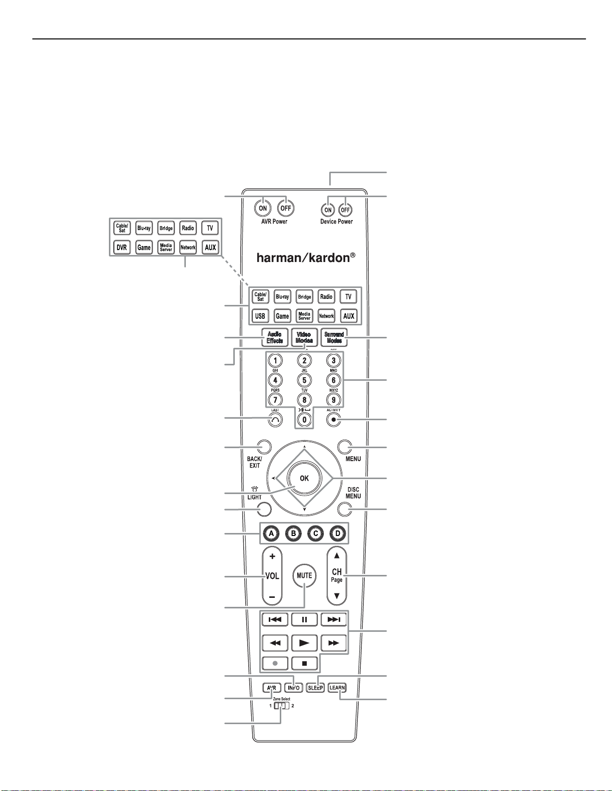
System Remote Control Functions
AVR Power On/Off
AVR Power On/Off
Source Selector
Source Selector
Buttons (AVR 2650/AVR 265)
Buttons (AVR 2650/AVR 265)
Source Selector
Buttons (AVR 3650/AVR 365)
Buttons
Source Selector
(AVR 3650/AVR 365)
Audio Effects
Audio Effects
Video Modes
Video Modes
Buttons
Buttons
Button
Button
Button
Button
System Remote Control Functions
IR Transmitter Lens
Device Power On/Off
Buttons
Surround Modes
Button
Number
Buttons
Last Channel
Last Channel
Button
Button
Back/Exit
Back/Exit
Button
Button
OK Button
OK Button
Backlight Button
Backlight Button
(AVR 3650/AVR 365 only)
(AVR 3650/AVR 365 only)
A/B/C/D Buttons
A/B/C/D Buttons
Volume Up/Down
Volume Up/Down
Buttons
Buttons
Mute Button
Mute Button
Info Button
Info Button
AVR Button
AVR Button
Zone Selector
Zone Selector
Switch
Switch
Activity Button
Menu Button
Up/Down/Left/Right
Buttons
Disc Menu
Button
Channel Up/Down and
Page Buttons
Transport Control
Buttons
Sleep Button
Learn Button
(AVR 3650/AVR 365 only)
ontinued on next pa
Page 11

d
AVR 2650 harman/kardon
11
AVR
System Remote Control Functions, continue
In addition to controlling the AVR, the AVR remote is capable of controlling eight other
devices, including an iPod/iPhone device docked in a The Bridge IIIP docking station
connected to the AVR. During the installation process, you may program the codes for
each of your source components into the remote. (See Program the Remote to Control
Your Source Devices and TV, on page 23, for programming information.) To operate
a component, press its Source Selector button to change the remote’s control mode.
A button’s function depends on which component is being controlled. See Table A13
in the Appendix for listings of the functions for each type of component. Most of
the buttons on the remote have dedicated functions, although the precise codes
transmitted vary depending on the specific device being controlled. Due to the wide
variety of functions for various source devices, we have included only a few of the
most-often used functions on the remote: alphanumeric keys, transport controls,
television-channel control, menu access and power on and off. Buttons dedicated to
the AVR – AVR Power On/Off, Audio Effects, Video Modes, Surround Modes, Volume,
Mute and Sleep Settings – are available at any time, even when the remote is
controlling another device. To return the remote to the AVR control mode at any time,
press the Setup button.
AVR Power On/Off buttons: Press these buttons to turn the AVR on and off. The Main
Power switch on the AVR’s rear panel must be on for this button to work.
IR Transmitter Lens: As buttons are pressed on the remote, infrared codes are
emitted through this lens.
Device Power On/Off buttons: Press a device’s Source Selector button, then press
these buttons to turn the device on and off.
Source Selector buttons: Press one of these buttons to select a source device, e.g.,
Blu-ray, Cable/Sat, Radio, etc. This action will also turn on the AVR and switch the
remote’s control mode to operate the selected source device. NOTE: The first press of
the Radio Source Selector button switches the AVR to the last-used tuner band (AM,
FM or SIRIUS). Each successive press changes the band.
Audio Effects button: Press this button to access the Audio Effects submenu, which
allows adjustment of the AVR’s tone and other audio controls. See the Set Up Your
Sources section, on page 26, for more information.
Video Modes button: Press this button for direct access to the Video Modes
submenu, which contains picture adjustments you can use after you have adjusted
the picture settings on your TV or video display. See the Advanced Functions section,
on page 33, for more information.
Surround Modes button: Press this button to access the Surround Modes submenu.
Select a surround-mode category: Auto Select, Virtual Surround, Stereo, Movie, Music
or Game. When you select the category, it is highlighted and the surround mode
changes.
To change the surround mode for the selected category, press the OK button when the
menu line is highlighted and use the Up/Down buttons to select one of the available
surround-mode options. Press the OK button; or press the Back/Exit button to exit the
Surround Modes menu and display the next higher menu in the hierarchy. See the
Advanced Functions section, on page 33, for more information.
Number buttons: Use these buttons to enter numbers for radio-station frequencies
or to select station presets.
Last Channel button: When controlling a cable, satellite or HDTV set-top box or a TV,
press this button to return to the previous television channel.
Activity button: With this button you can program the remote to store up to 11
different Macros (Activities). (A Macro is a series of commands that are transmitted
by a single button press.) Execute a Macro by pressing this button, followed by the
Number button (or the AVR Power On button) into which you programmed the Macro.
See Programming Macro (Activity) Commands, on page 41, for more information.
System Remote Control Functions, continued
Back/Exit button: Press this button to return to the previous menu or to exit the
menu system.
Menu button: This button is used within the tuner menus (including SIRIUS Radio)
and The Bridge IIIP control menu, and is also used to display the main menu on some
source devices. To display the AVR’s menu system, press the Setup button.
Up/Down/Left/Right buttons: These buttons are used to navigate the menu system
and to operate the tuner.
OK button: This button is used to select items from the menu system.
Backlight button (AVR 3650/AVR 365 only): Press this button to illuminate the
buttons on the remote. Press it again to turn the backlight off, or wait 5 seconds after
the last button press for the light to turn off on its own.
Disc Menu button: To display the disc’s menu while a DVD or Blu-ray Disc is playing,
press the Blu-ray Source Selector button, then press this button.
A/B/C/D buttons: These buttons can be used as additional source buttons and can
also operate certain functions when used with some source devices. See Table A13
in the Appendix for details. These buttons are also used with a Teletext
television if your broadcast, cable or satellite provider offers Teletext service.
Volume Up/Down buttons: Press these buttons to raise or lower the volume.
Channel Up/Down and Page buttons: When the tuner has been selected, press
these buttons to select a preset radio station. While operating a cable, satellite or
HDTV set-top box or a television, press these buttons to change channels.
Mute button: Press this button to mute the AVR’s speaker-output connectors and
headphone jack. To restore the sound, press this button or adjust the volume.
Transport Control buttons: These buttons are used to control source devices and
The Bridge IIIP.
Info button: Press to display the AVR’s Info Menu, which contains the settings for
the current source.
Setup button: Press to display the AVR’s Main Menu or to switch the remote to the
AVR control mode.
Sleep button: Press this button to activate the sleep timer, which turns off the
receiver after a programmed period of time. Each press increases the time by 10
minutes, up to 90 minutes – ending with the “Sleep Off” message.
Learn button (AVR 3650/AVR 365 only): The AVR 3650/AVR 365 remote is capable
of “learning” individual IR codes from the original remote that came with a source
device. See Program the Remote to Control Your Source Devices and TV, on page 23,
for more information.
Zone Selector switch: Use this switch to select whether the AVR commands will
affect the main listening area (Zone 1) or the remote zone of a multizone system
(Zone 2). For normal operation, leave the switch in the Zone 1 position.
®
-capable
Page 12
p
AVR 2650 harman/kardon
12
AVR
Types of Home Theater System Connections
There are different types of audio and video connections used to connect the AVR to your
speakers, your TV or video display, and your source devices. The Consumer Electronics
Association has established the CEA® color-coding standard.
Analog Audio Connection Color
Front Left/Right White/Red
Center Green
Surround Left/Right Blue/Gray
Surround Back/Front Height Left/Right Brown/Tan
Subwoofer Purple
Digital Audio Connection Color
Coaxial (input or output) Orange
Optical Input Black
Optical Record Output Gray
Analog Video Connection Color
Component Video Red/Green/Blue
Composite Video Yellow
Speaker Connections
Speaker cables carry an amplified signal from the AVR’s speaker terminals to each
loudspeaker. They contain two wire conductors, or leads, that are differentiated in some
way, such as with colors or stripes.
The differentiation helps you maintain proper polarity, without which your system’s lowfrequency performance can suffer. Each speaker is connected to the AVR’s speakeroutput terminals using two wires, one positive (+) and one negative (–). Always connect
the positive terminal on the speaker, which is usually colored red, to the positive terminal
on the receiver, which is colored as indicated in the Connection Color Guide Table, above.
The negative terminals on the speakers and the AVR are black.
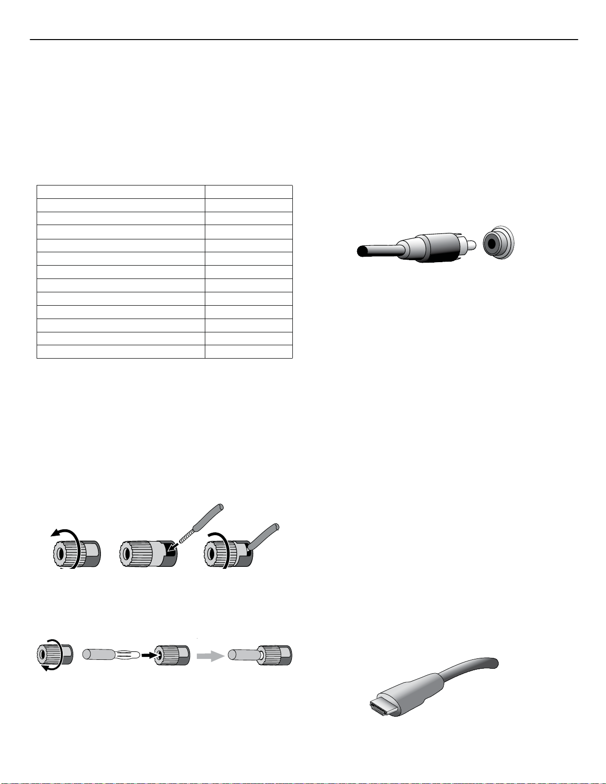
Your AVR uses binding-post speaker terminals that can accept bare-wire cables or
banana plugs. Bare-wire cables are installed as shown below:
1. Unscrew Cap 3. Tighten Cap2. Insert Bare Wire
Banana plugs are inserted into the hole in the middle of the terminal cap, as shown
below:
A. Tighten Cap
B. Insert Banana Connector
into Hole in Cap
Types of Home Theater System Connections
Subwoofer Connections
The subwoofer is a speaker dedicated to reproducing only the low (bass) frequencies,
which require more power. To obtain the best results, most speaker manufacturers offer
powered subwoofers that contain their own amplifiers. Use a single RCA audio cable to
make a line-level (non-amplified) connection from the AVR’s Subwoofer connector to a
corresponding input jack on the subwoofer.
Although the AVR’s purple subwoofer output looks similar to a full-range analog audio
jack, it is filtered so that only the low frequencies pass through it. Don’t connect this
output to any device other than a subwoofer.
Source Device Connections
Audio and video signals originate in source devices (components where a playback
signal originates) such as your Blu-ray Disc or DVD player, CD player, DVR (digital
video recorder) or other recorder, tape deck, game console, cable or satellite television
tuner, an iPod or iPhone (docked in an optional The Bridge IIIP docking station) or an
MP3 player. The AVR’s FM/AM tuner also counts as a source, even though no external
connections are needed other than the FM and AM antennas and an optional SIRIUS
tuner module. Separate connections are required for the audio and video portions of the
source device’s signal, except for digital HDMI connections. The types of connections
you use will depend upon the capabilities of the source device and of your TV or video
display.
Digital Audio Connections – HDMI
There are two types of audio connections – digital and analog. Digital audio signals are
required for listening to sources encoded with digital surround modes, such as Dolby
Digital and DTS, or for uncompressed PCM digital audio. Your AVR has three types of
digital audio connections: HDMI, coaxial and optical. Do not use more than one type of
digital audio connection for each source device. However, it’s okay to make both analog
and digital audio connections to the same source.
Your AVR is equipped with five rear-panel HDMI input connectors, and one HDMI monitor
output connector. (The AVR 3650 and AVR 365 also have a front-panel HDMI input
connector.) HDMI technology enables digital audio and video information to be carried
using a single cable, delivering the highest quality picture and sound. If your TV or video
display device has an HDMI input connector, make a single HDMI connection from each
source device to the AVR. Usually, a separate digital audio connection is not required.
The AVR’s HDMI monitor output connection contains an Audio Return Channel (ARC) that
carries a digital audio signal from your TV or video display back to the AVR. It allows
you to listen to HDMI devices that are connected directly to your TV (such as an Internet
connection) without making an additional connection from the device to the AVR. The
ARC signal is active when the TV source is selected. See System Settings, on page 39,
for more information.
The HDMI connector is shaped for easy plug-in (see illustration, below), and HDMI cable
runs are limited to about 10 feet (3m). If your video display has a DVI input and is
HDCP-compliant, use an HDMI-to-DVI adapter (not included), and make a separate audio
connection.
Always connect the colored (+) terminal on the AVR to the (+) terminal on the speaker
(usually red), and the black (–) terminal on the AVR to the (–) terminal on the speaker
(usually black).
IMPORTANT: Make sure the ( + ) and ( – ) bare wires do not touch each other or
the other terminal. Touching wires can cause a short circuit that can damage your
receiver or amplifier.
Page 13
AVR 2650 harman/kardon
13
AVR
Digital Audio Connections – Coaxial
Coaxial digital audio jacks are usually color-coded in orange. Although they look like
standard RCA-type analog jacks, you should not connect coaxial digital audio outputs to
analog inputs or vice versa.
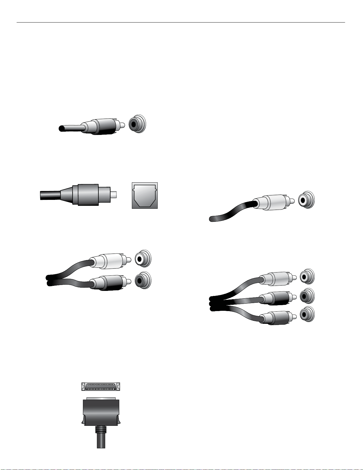
Digital Audio Connections – Optical
Optical digital audio connectors are normally covered by a shutter to protect them from
dust. The shutter opens as the cable is inserted. Optical input connectors are colorcoded using a black shutter, while optical outputs use a gray shutter.
Types of Home Theater System Connections
Video Connections
Many source devices output both audio and video signals (e.g., Blu-ray Disc, DVD
player, cable television box, HDTV tuner, satellite box, VCR, DVR). In addition to an audio
connection as described above, make a video connection for each of these source
devices. Make only one type of video connection for each device.
Digital Video Connections
If you have already connected a source device to one of the AVR’s HDMI input connectors,
you have automatically made a video connection for that device, since the HDMI cable
carries both digital audio and digital video signals.
Analog Video Connections – Composite Video
Your AVR uses two types of analog video connections: composite video and component
video.
Composite video is the basic connection most commonly available. Both the chrominance
(color) and luminance (intensity) components of the video signal are transmitted using a
single cable. The jack is usually color-coded yellow and looks like an analog audio jack.
Do not connect a composite video jack to an analog audio or coaxial digital audio jack,
or vice versa.
Analog Audio Connections
Two-channel analog connections require a stereo audio cable, with one connector for
the left channel (white) and one for the right channel (red). These two connectors are
attached to each other.
For source devices that have both digital and analog audio outputs, you may make both
connections. If you are going to be setting up a multizone system, remember that Zone
2 is an audio-only zone (the AVR does not have a Zone 2 video output). Therefore, make
analog connections for any audio source devices (such as a CD changer) that you will
want available for listening in Zone 2 at all times.
The analog connections also feed the analog record outputs. You may record materials
from Blu-ray Disc recordings, DVDs or other copy-protected sources using only analog
connections. Remember to comply with all copyright laws if you choose to make a copy
for your own personal use.
The Bridge IIIP Connection
Your AVR includes a proprietary, dedicated connector for an optional The Bridge IIIP
docking station for the iPod or iPhone. The Bridge IIIP outputs analog audio to the AVR
and is available as a source to Zone 2 in a multizone system.
Analog Video Connections – Component Video
Component video separates the video signal into three components – one luminance
(“Y”) and two sub-sampled color signals (“Pb” and “Pr”) – that are transmitted using
three separate cables that are color-coded green (Y), blue (Pb) and red (Pr). Component
video cables that join three separate green, blue and red connectors into a single cable
are sold separately.
If your TV or video display has an HDMI connection, we recommend it as the best quality
connection. Your AVR converts composite and component analog video input signals to
the HDMI format, upscaling them to high-definition 1080p resolution.
15
Page 14
AVR 2650 harman/kardon
14
AVR
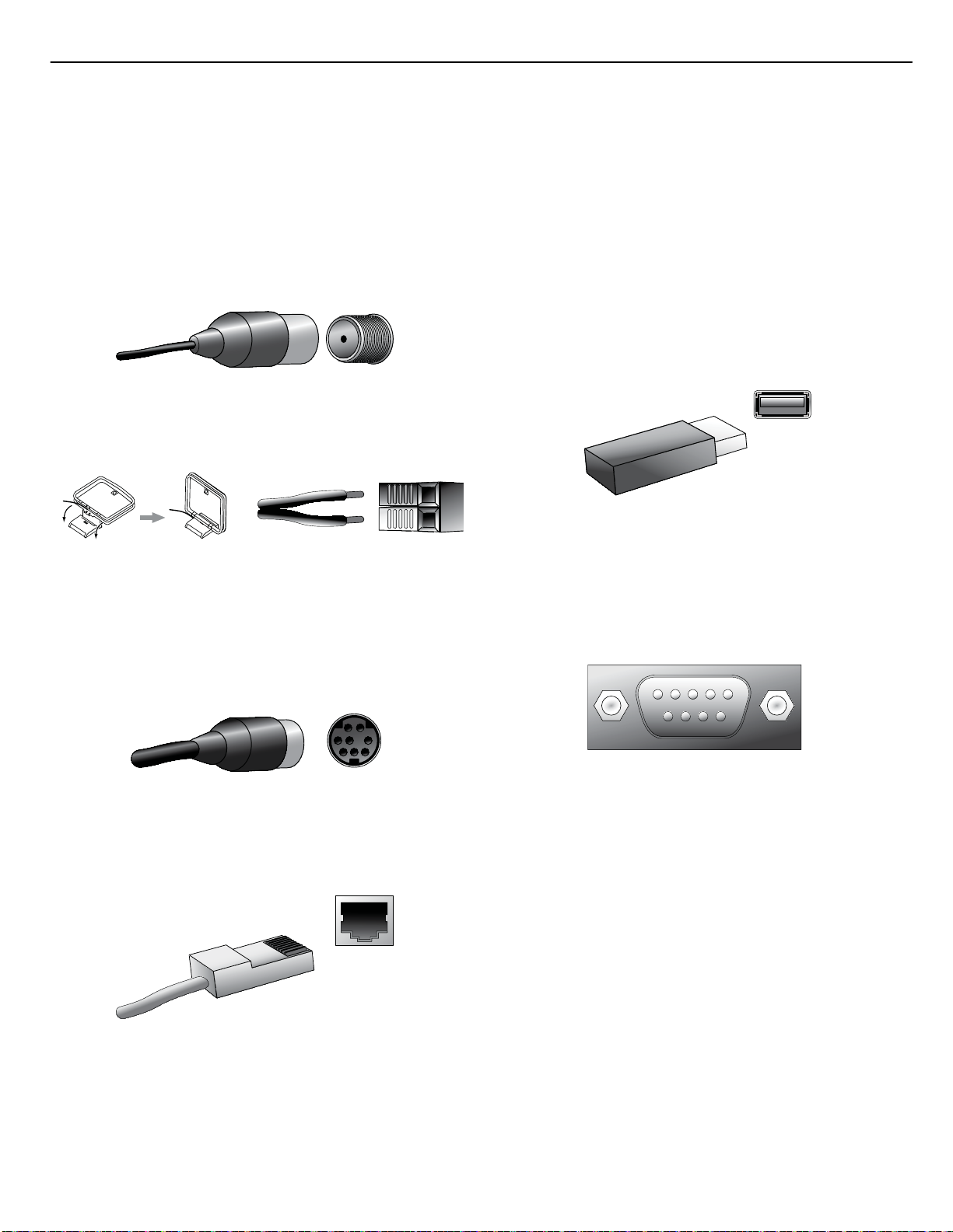
Radio Connections
Your AVR uses separate terminals for the included FM and AM antennas. The FM antenna
uses a 75-ohm F-connector.
The AM antenna connector uses spring-clip terminals. After assembling the antenna as
shown below, press the levers to open the connectors, insert the bare wires into the
openings, and release the levers to secure the wires. The antenna wires are not polarized,
so you can insert either wire into either connector.
SIRIUS Satellite Radio
To enjoy SIRIUS satellite radio, purchase a SIRIUSConnect tuner module and a subscription
to the SIRIUS service. Visit www.sirius.com for information on SIRIUSConnect tuner
modules. The SiriusConnect modules include an eight-pin DIN cable for connection to
the eight-pin jack on the AVR, allowing you to control the tuner module via the AVR.
Although you may also use a “plug-and-play” tuner module equipped with standard
audio connections, you will not be able to use the AVR to control the SIRIUS tuner.
Types of Home Theater System Connections
USB Port
The USB port on your AVR is used for firmware upgrades. If an upgrade for the AVR’s
operating system is released in the future, you will be able to download it to the AVR using
this port. Complete instructions will be provided at that time.
In addition to performing firmware upgrades, the AVR 3650/AVR 365 can play MP3 and
WMA audio files from a USB device inserted into the USB port. Insert the device into the
USB port with the device’s plug oriented so it fits all the way into the port. You may insert
or remove the device at any time – there is no installation or ejection procedure.
IMPORTANT: Do not connect a PC or other USB host/controller to the AVR’s USB
port, or you may damage both the AVR and the other device.
RS-232 Connector
Your AVR’s RS-232 serial port may be connected to an external control system to allow
it to transmit control commands to the AVR. The port is bidirectional so that the AVR
can transmit status updates to the control device. Connecting and using the RS-232
port requires considerable technical knowledge and is best left to a professional custom
installer.
Network Connector
The AVR’s Network connector allows you to enjoy Internet radio or content from other
DLNA-compatible devices that are connected to the same network. Use a Cat. 5 or
Cat. 5E cable to connect the AVR’s RJ-45 connector to your home network.
Page 15
AVR 2650 harman/kardon
15
AVR
Making Connections
CAUTION: Before making any connections to the audio/video receiver, ensure
that the AVR’s AC cord is unplugged from the receiver and the AC outlet.
Making connections with the receiver plugged in and turned on could damage
the speakers.
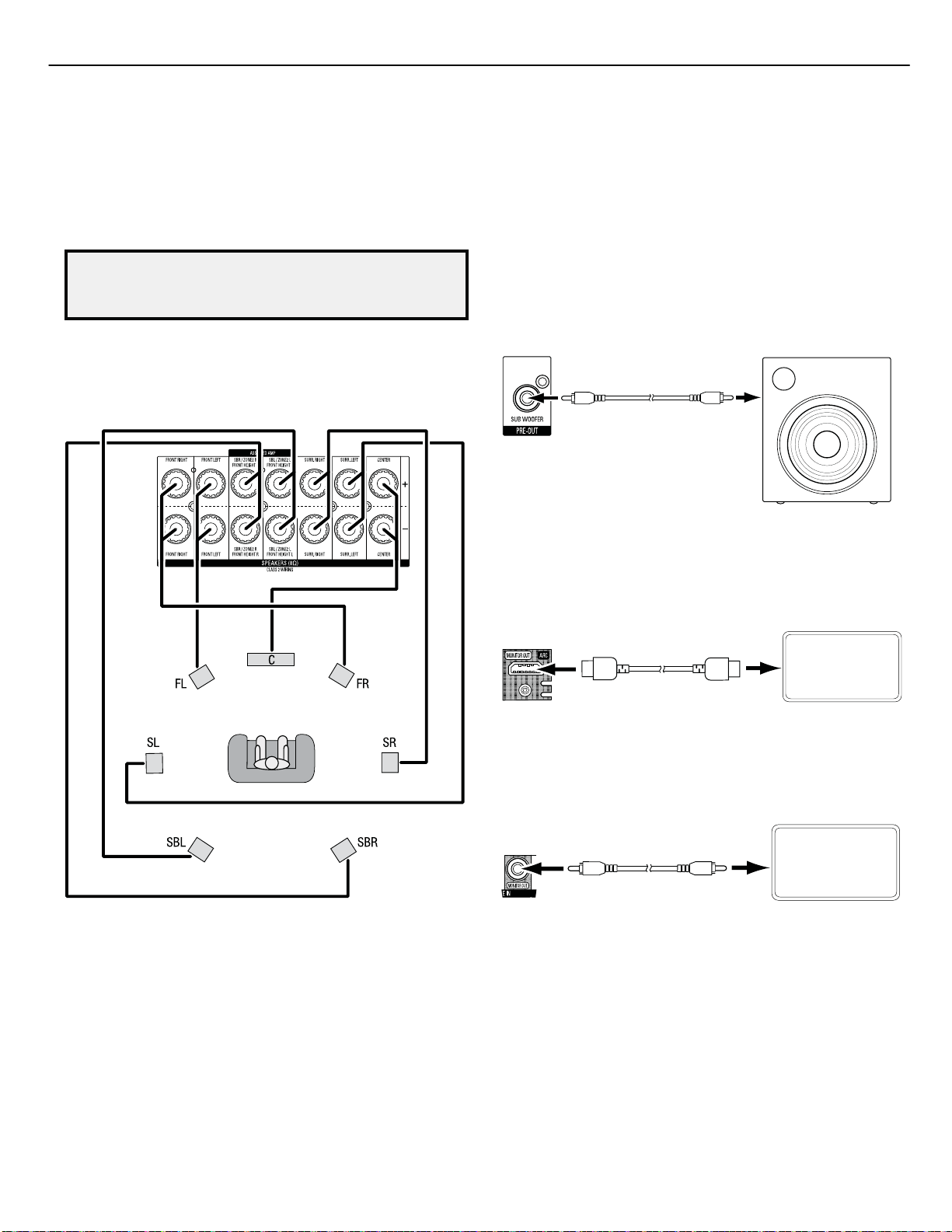
Connect Your Speakers
After you have placed your loudspeakers in the room as explained in Place Your Speakers,
on page 13, connect each speaker to its color-coded terminal on the AVR as explained
in Speaker Connections, on page 14. Connect the speakers as shown in the illustration.
Making Connections
Connect Your Subwoofer
Use a single RCA audio cable to connect the AVR’s Subwoofer connector to your
subwoofer as explained in Subwoofer Connections, on page 14. Consult your subwoofer’s
user manual for specific information about making connections to it.
AVR Subwoofer
AVR Subwoofer
Connector
Connector
Single
Single
RCA Audio Cable
RCA Audio Cable
(not supplied)
(not supplied)
Connect Your TV or Video Display
If your TV has an HDMI connector: Use an HDMI cable (not included) to connect it to the
AVR’s HDMI Monitor Out connector. You do not need to make any other connections to
your TV from the receiver or from any of your video source components.
Powered
Powered
Subwoofer
Subwoofer
NOTE: If you installed front height speakers, connect them as shown for the SBL and
SBR speakers.
Receiver
HDMI Monitor Out
HDMI Monitor Out
Connector
Connector
HDMI Cable
HDMI Cable
(not supplied)
(not supplied)
If your TV does not have an HDMI connector: Use a composite video cable (not
included) to connect the AVR’s Composite Monitor Out connector to your TV’s composite
video connector.
Receiver
Composite
Composite
Monitor Out
Monitor Out
Connector
Connector
Composite Video Cable
Composite
(not supplied)
Video Cable
(not supplied)
NOTE: The HDMI connection to your TV is preferred. If you use the composite video
connection to your TV, you will not be able to view the AVR’s on-screen menus.
TV
TV
Page 16
g
R
AVR 2650 harman/kardon
16
AVR
Making Connections
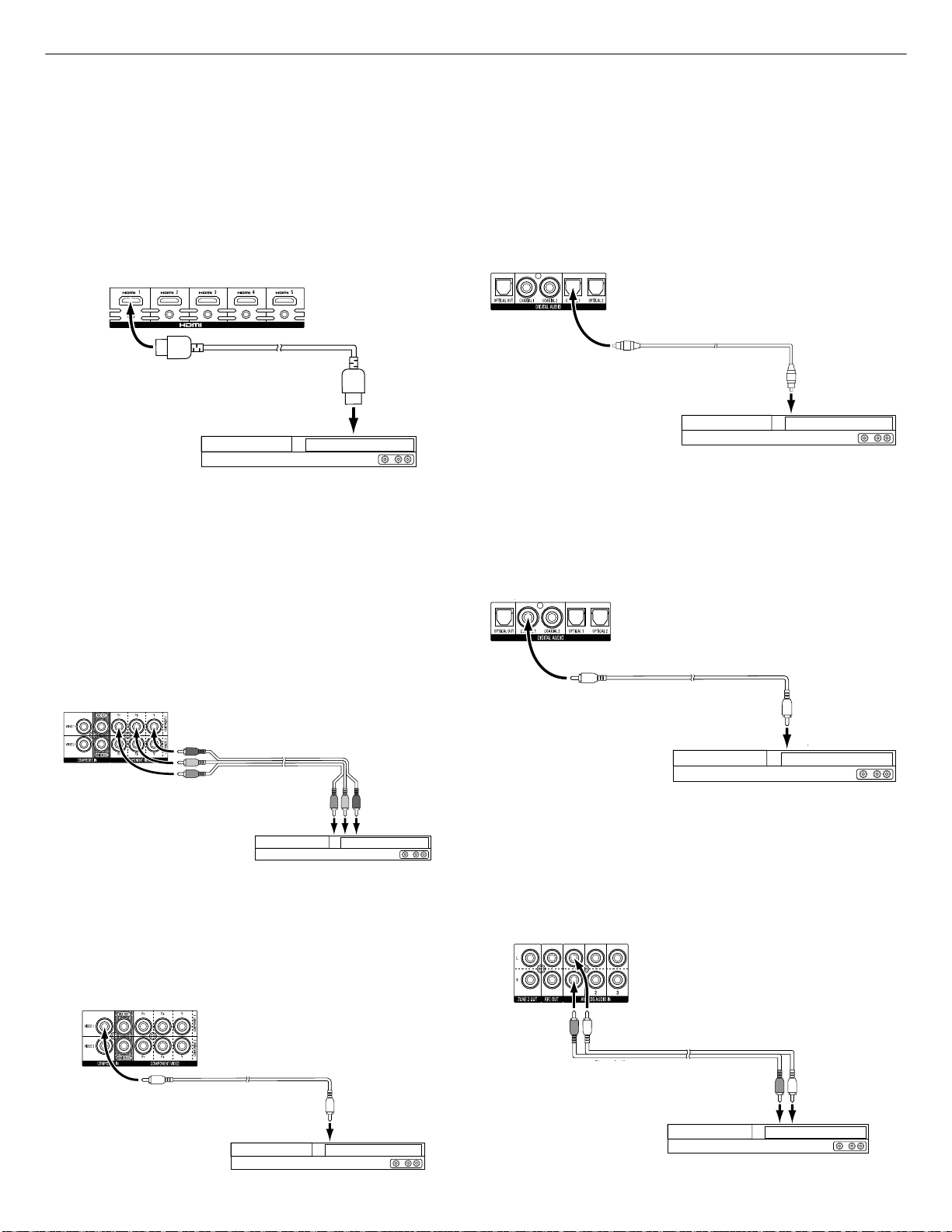
Connect Your HDMI Devices
If any of your source devices have HDMI connectors, using them will provide the best
possible video and audio performance quality. Since the HDMI cable carries both digital
video and digital audio signals, you do not have to make any additional audio connections
for devices you connect via an HDMI cable.
Receiver
HDMI Connectors
HDMI Cable
HDMI Cable
(not supplied)
(not supplied)
To HDMI
To HDMI
Output
Output
HDMI-Equipped
Source Device
NOTE: If you have HDMI devices (such as an Internet connection) already connected
directly to your TV, you can feed their sound to the AVR via the HDMI Monitor Out
connector’s Audio Return Channel, and they will not require additional connections to
the AVR.
Connect Your Component Video Devices
If any of your video source devices have component video connectors (and do not have
HDMI connectors), using the component video connectors will provide superior video
performance. You will also need to make an audio connection from the device to the
receiver.
Receiver
Video Connectors
Connect Your Optical Digital Video Devices
If your non-HDMI source devices have optical digital outputs, connect them to the AVR’s
optical digital audio connectors. NOTE: Make only one type of digital connection (HDMI,
optical or coaxial) from each device.
Receiver
Digital Audio Connectors
Optical Digital Audio
Optical Digital Audio
Cable (not supplied)
Cable (not supplied)
To Optical Digital
To Optical Digital Audio
Output
Audio Output
Optical Digital-Equipped
Source Device
Connect Your Coaxial Digital Audio Devices
If your non-HDMI source devices have coaxial digital outputs, connect them to the AVR’s
coaxial digital audio connectors. NOTE: Make only one type of digital connection (HDMI,
optical or coaxial) from each device.
Receiver
Digital Audio Connectors
Coaxial Digital Audio
Coaxial Digital Audio
Cable (not supplied)
Cable (not supplied)
To Coaxial Digital
To Coaxial Digital Audio
Output
Audio Output
Component Video
Component Video
Cable (not supplied)
Cable (not supplied)
To Component Video
To Component Video
Outputs
Outputs
Component Video-Equipped
Source Device
Connect Your Composite Video Devices
Use composite video connectors for video source devices that don’t have HDMI or
component video connectors. You will also need to make an audio connection from the
source device to the receiver.
Receiver
Video Connectors
Composite Video
Composite Video
Cable (not supplied)
Cable (not supplied)
To Composite Video
To Composite Video
Output
Output
Composite Video-Equipped
Source Device
Coaxial Digital-Equipped
Source Device
Connect Your Analog Audio Devices
Use the AVR’s analog audio connectors for source devices that don’t have HDMI or digital
audio connectors. NOTE: If you’re installing a multizone system, make analog audio
connections for any source devices you want to be able to listen to in Zone 2. Only analog
sources are available in Zone 2.
Receiver
Analog Audio Connectors
eceiver
Analog Audio Connectors
Stereo Audio
Stereo Audio Cable
Cable (not supplied)
(not supplied)
To Stereo Analog
To Stereo Analog Audio
Output
Audio Output
Analog Source Device
19
Page 17
AVR 2650 harman/kardon
17
AVR
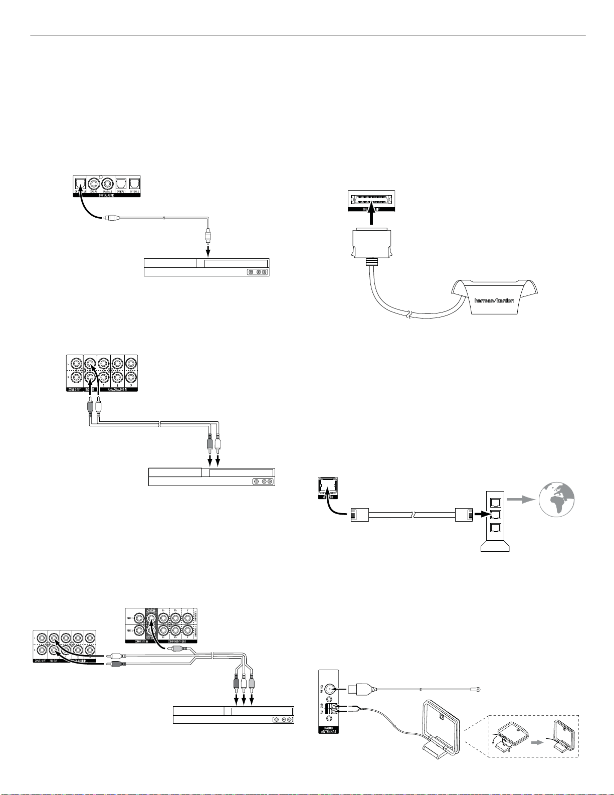
Connect Your Audio Recorders
Connect a digital audio recorder’s optical digital input to the AVR’s optical digital output.
You can record both coaxial and optical digital audio input signals.
Digital Audio Recorder Connector
Connect an analog audio recorder’s inputs to the AVR’s analog audio Rec Out connectors.
You can record any analog audio input signal.
Analog Audio Recorder Connectors
Receiver
Receiver
Optical Digital Audio
Optical Digital Audio
Cable (not supplied)
Cable (not supplied)
To Optical Digital
To Optical Digital
Record Input
Record Input
Digital
Recording Device
Making Connections
Connect The Bridge IIIP
Connect an optional The Bridge IIIP to the AVR’s The Bridge IIIP connector. Insert the plug
until it snaps into place in the connector. IMPORTANT: Connect The Bridge IIIP only
with the AVR’s power turned OFF.
AVR
The Bridge IIIP
Connector
The Bridge IIIP
The Bridge IIIP
Dock your iPod or iPhone (not included) in The Bridge IIIP, and you may listen to its audio
through your high-performance audio/video system. You may also view still images or
video materials stored on a photo- or video-capable iPod or iPhone that supports video
browsing. You can use the AVR remote to control the iPod, with navigation messages
displayed on the AVR’s front panel and on a video display connected to the AVR.
Stereo Audio
Stereo Audio
Cable (not supplied)
Cable (not supplied)
To Stereo Analog
To Stereo Analog Record
Inputs
Record Inputs
Analog
Recording Device
Connect Your Video Recorder
Connect an analog video recorder’s video input connector to the AVR’s Composite Video
Rec Out connector. You can record any composite video signal. NOTE: To record the audio
and video from the source device, connect the AVR’s analog audio Rec Out connectors to
the analog video recorder’s audio inputs.
Receiver Analog Video
Recorder Connectors
Receiver Analog Audio
Recorder Connectors
Analog Audio/Video
Cable (not supplied)
To Analog
Audio/Video
Record Inputs
Connect to Your Home Network
Use a Cat. 5 or Cat. 5E cable (not supplied) to connect the AVR’s Network connector to
your home network to enjoy Internet radio and content from DLNA-compatible devices
that are connected to the network.
Receiver
Receiver
Network
Network
Connector
Connector
Cat. 5/5E Cable
Cat. 5/5E Cable
(not supplied)
(not supplied)
Network
Network
Modem
Modem
To
To
Internet
Internet
and LAN
and LAN
Connect the Radio Antennas
• Connect the supplied FM antenna to the AVR’s FM 751 antenna connector. For the best
reception, extend the FM antenna as far as possible.
• Bend and fold the base of the supplied AM antenna as shown and connect the antenna
wires to the AVR’s AM and Gnd connectors. (You can connect either wire to either
connector.) Rotate the antenna as necessary to minimize background noise.
AVR
Antenna
Connectors
FM Antenna (supplied)
Analog Video
Recording Device
20
AM Antenna
(supplied)
Bend and fold base
Page 18
AVR 2650 harman/kardon
18
AVR
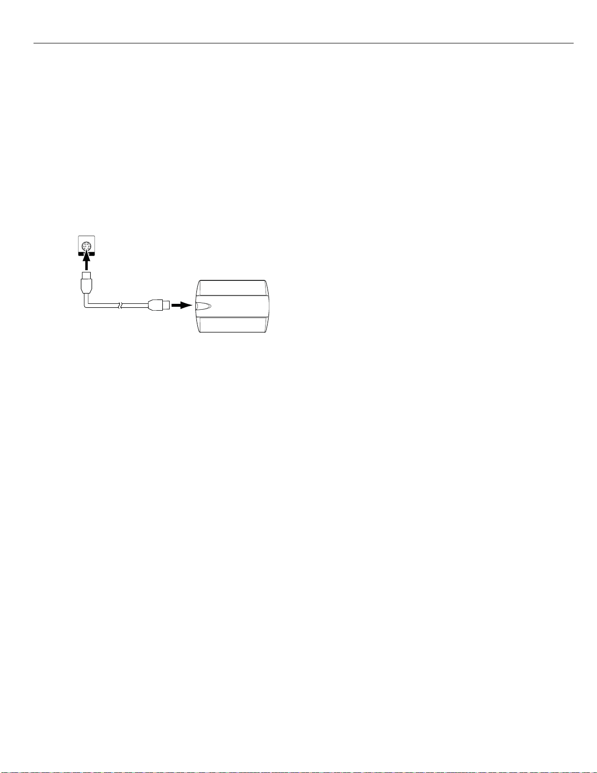
Connect a SIRIUSConnect Radio Tuner (AVR 3650 and AVR 2650 only)
Connect the multi-pin DIN cable supplied with the SIRIUSConnect tuner to the AVR’s
SIRIUS Tuner connector and to the corresponding connector on the SIRIUS module. The
AVR will supply power to the SIRIUS module so you will not need to connect the power
supply included with the module. You will need to purchase a SIRIUS radio subscription
and activate the tuner module, following the instructions included with the SIRIUS module
and from the SIRIUS Web site at www.sirius.com.
AVR
SIRIUS Tuner
Connector
SIRIUSConnect Tuner
Eight-Pin DIN Cable
(supplied with SIRIUS tuner)
Making Connections
Install a Multizone System
Page 19
AVR 2650 harman/kardon
19
AVR
Operating Your AVR
Now that you have installed your components and completed a basic configuration, you
are ready to begin enjoying your home theater system.
Controlling the Volume
Adjust the volume either by turning the front-panel Volume knob (clockwise to increase
volume or counterclockwise to decrease volume) or by pressing the Volume Up/Down
buttons on the remote. The volume is displayed as a negative number of decibels (dB)
below the 0dB reference point (-90dB – +10dB).
0dB is the maximum recommended volume for your AVR. Although it’s possible to turn
the volume to a higher level, doing so may damage your hearing and your speakers. For
certain more dynamic audio materials, even 0dB may be too high, allowing for damage
to equipment. Use caution with regard to volume levels.
To change the volume level display from the default decibel scale to a 0-to-90 scale,
adjust the Volume Units setting in the System Settings menu, as described in System
Settings, on page 39.
Muting the Sound
To mute all speakers and the headphones, press the Mute button on the remote. Any
recording in progress will not be affected. The MUTE message will appear in the display
as a reminder. To restore the sound, press the Mute button again, or adjust the volume.
Dolby Volume
Your AVR implements Dolby Volume processing, which can improve the audio performance
of the system by revealing subtle details in the sound, even at normal home-listening
volumes.
One concern of the typical home theater listener is that volumes can vary widely for
different programs played by a source (e.g., television commercial advertisements are
often much louder than the main program). Another is that details heard in the recording
studio at typically high reference volumes are lost at the lower volumes used by many
listeners at home.
The AVR uses two Dolby Volume techniques to address these issues. The Leveler module
maintains a consistent listening volume within a source (e.g., commercial television or
different tracks on a USB drive or mix CD). The Modeler module endeavors to re-create
the reference presentation that was heard in the recording studio without losing portions
of the program at the typically lower volume levels often used in the home. When the
Modeler module is active, you may notice details of the performance that were hidden
when the program was played on other equipment.
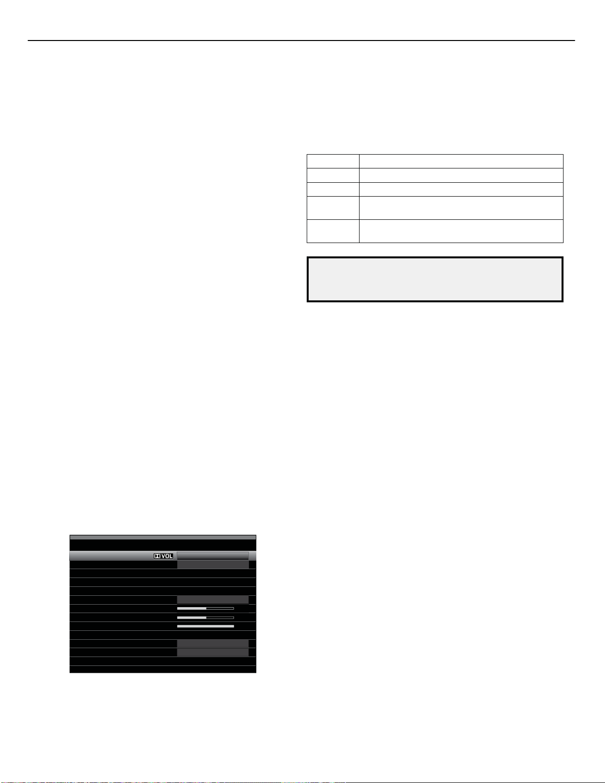
To adjust the Dolby Volume setting, press the Audio Effects button. The Audio Effects
submenu will appear.
Audio Effects – Cable/Sat
Dolby Volume:
PLIIz Height Gain:
Edit: Dolby PLII Music
Edit: Dolby PLIIx Music
Tone Control:
Treble:
Bass:
LFE Trim:
MP3 Enhancer
EZSET/EQ:
After you highlight the Dolby Volume setting, each press of the OK button will switch to
one of the options in the table below. The settings do not refer to the volume level, which
is adjusted normally using the AVR’s Volume Control, but rather to the amount of Dolby
Volume processing desired.
Medium
Low
On
Off
Off
Operating Your AVR
Setting Effect
Off No Dolby Volume processing
Low Only Dolby Volume Modeler module is active
Medium
Max
NOTE: Dolby Volume processing is compatible with sources recorded at a sampling
rate of 48kHz. High-resolution sources, such as DTS 96/24 programs, will be
decoded at 48kHz. DTS 96/24 programs will be played in DTS 5.1 mode. To hear
DTS 96/24 materials in high resolution, turn off Dolby Volume processing.
Dolby Volume Calibration
Dolby Volume calibration allows you to adjust the operation of the Dolby Volume
circuitry to match your particular speakers and listening environment. The Dolby Volume
circuitry in your AVR is factory-calibrated with average speaker sensitivity in mind;
however, different speakers may have different sensitivities, which will affect the overall
performance of the Dolby Volume circuitry. Use Dolby Volume calibration to adjust the
calibration of the circuitry according to the specific speakers you have.
The average home audio speaker sensitivity is 88dB SPL (1 watt/1 meter). Check the
sensitivity specification for your loudspeakers, found in the owner’s manual or on the
manufacturer’s Web site. If your speakers have a sensitivity rating greater than 88dB SPL,
increase Dolby Volume calibration by the difference between your speakers’ sensitivity
and 88dB. If they have a sensitivity rating of less than 88dB SPL, decrease Dolby Volume
calibration by the difference between your speakers’ sensitivity and 88dB.
To adjust the Dolby Volume calibration, press the AVR button and select the “System”
menu. Scroll to the Dolby Volume calibration line, which defaults to 0dB. Use the Left/
Right buttons to adjust the setting within the range of –10dB to +10dB.
Listening Through Headphones
Plug the 1/4-inch stereo plug on a pair of headphones into the front-panel Phones jack
for private listening. The default Headphone Bypass mode delivers a conventional twochannel signal to the headphones. Press the Surround Modes button on the front panel
or the remote to switch to HARMAN headphone virtual surround processing, which
emulates a 5.1-channel speaker system. No other surround modes are available for the
headphones.
Selecting a Source
There are three different ways to select a source:
• Press the front-panel Source List button. Use the Up/Down buttons to scroll through the
sources, and press the OK button to select the source being displayed.
• Using the on-screen menus, press the AVR button, highlight “Source Select” and press
the OK button. Scroll to the desired source in the slide-in menu and press the OK button.
• You can directly select any source by pressing its Source Selector button on the remote.
The AVR selects the audio and video inputs assigned to the source, and any other settings
you made during setup.
The source name, the audio and video inputs assigned to the source, and the surround
mode will appear on the front panel. The source name and active surround mode will also
briefly appear on the TV screen.
Both Modeler and Leveler modules are active;
Leveler module has a value of 3
Both Modeler and Leveler modules are active;
Leveler module has a value of 9
Page 20
AVR 2650 harman/kardon
20
AVR
Video Troubleshooting Tips
If there is no picture:
• Check the source selection and video input assignment.
• Check all connections for a loose or incorrect connection.
• Check the video input selection on the TV/display device.
• Press the front-panel Resolution button and use the Up/Down buttons until the
correct video output resolution is selected and a picture appears. The CANCEL
message will also appear. Press the Down button to view the ACCEPT option, then
press the OK button.
Additional Tips for Troubleshooting HDMI Connections
• Turn off all devices (including the TV, the AVR and any source components).
• Unplug the HDMI cables, starting with the cable between the AVR and the TV, and
continuing with the cables between the AVR and each source device.
• Carefully reconnect the cables from the source devices to the AVR. Connect the
cable from the AVR to the TV last.
• Turn on the devices in this order: TV, AVR, source devices.
NOTE: Depending upon the particular components involved, the complexity of
the required communication between HDMI components may cause delays of
up to a minute in the completion of some actions, such as input switching or
switching between SD and HD channels.
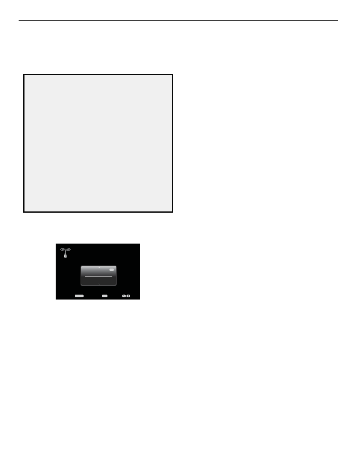
Listening to FM and AM Radio
Select the Radio source. A screen similar to the one in the illustration below will appear.
(Note: The SIRIUS band uses a different screen.)
AM/FM Radio
1
87.50
FM
MHz
Auto
Menu: Set Presets: Presets:
Use the Up/Down buttons or the Remote’s Channel buttons to tune a station (or
channel for SIRIUS Radio), as displayed on the front panel and on-screen display.
The AVR defaults to automatic tuning, meaning each press of the Up/Down buttons
scans up or down the frequency band until a station with acceptable signal strength
is found. To switch to manual tuning, in which each press of the Up/Down buttons
steps through a single tuning frequency increment, press the remote’s Menu button.
A slide-in menu will appear. Select “Mode,” and press the OK button to toggle
between automatic and manual tuning modes.
Once you have tuned an FM station, toggling the Mode setting also switches the radio
between stereo and monaural reception. (Mono reception may improve reception of
weaker stations.)
Preset Stations
You can store a total of 30 stations (AM and FM combined) as presets. When you
want to save the currently tuned station as a preset, press the OK button, and two
dashes will flash. Use the Number buttons to enter the desired preset number.
To tune to a preset station:
• Press the Left/Right buttons.
• Press the skip forward/skip backward Transport Control buttons.
• Press the Menu button and scroll to the desired preset, then press the OK button.
• Enter the preset number using the Number buttons. For presets 10 through 30,
press 0 before the preset number. For example, to enter preset 21, press 0-2-1.
OKMENU
Operating Your AVR
Listening to SIRIUS Satellite Radio
SIRIUS Satellite Radio delivers a variety of commercial-free music from categories
including pop, rock, country, R&B, dance, jazz, classical and many more, plus
coverage of all the top professional and college sports, including play-by-play games
from select leagues and teams. Additional programming includes expert sports talk,
uncensored entertainment, comedy, family programming, local traffic and weather,
and news from your most trusted sources. SIRIUS Satellite Radio is available to
residents of the U.S. (except Alaska and Hawaii) and Canada.
To listen to SIRIUS Satellite Radio, you’ll need to connect a SIRIUS tuner module (sold
separately) to the AVR’s SIRIUS Tuner connector. SIRIUS tuner modules that will work
with your AVR are available at www.sirius.com. Select a tuner module designated
for SIRIUS-Ready® audio components (also called SIRIUSConnect). A SIRIUSConnect
module is controlled by the AVR’s internal tuner, including 40 preset SIRIUS station
locations and remote control. Although you may also use a SIRIUS “plug-and-play”
unit with standard analog audio connections, you will not be able to enjoy the AVR’s
ease of control.
Installing the SIRIUS tuner module
Once you’ve purchased a SIRIUS tuner, you’ll need to install it, activate it and
subscribe to begin enjoying the service:
1. Using the cable included with the SIRIUS tuner module, plug the module into the
SIRIUS Tuner connector on the rear of the AVR.
2. Follow the instructions included with the SIRIUS tuner module to complete its
installation. NOTE: Pay particular attention to the instructions for installing and
orienting the SIRIUS antenna that is included with the SIRIUS tuner module.
3. Call 1-888-539-SIRI (7474) or visit sirius.com (U.S.) or siriuscanada.ca (Canada) to
activate your SIRIUS tuner module and subscribe to the SIRIUS service.
To listen to SIRIUS radio
Select SIRIUS Radio as the source in one of these ways:
• Press the Source List button on the front panel. Use the Up/Down buttons to scroll
to “SIRIUS Radio” and press the OK Button.
• Press the Radio Source Selector button on the remote repeatedly until SIRIUS Radio
is selected.
There are four ways to tune a SIRIUS radio channel:
• Use the Up/Down buttons or the Channel Up/Down buttons to scan through the
channel numbers.
• Use the Left/Right buttons to scan through any previously programmed preset
stations.
• After you have programmed presets, directly enter the preset number (1 through
40) using the Number buttons. For two-digit positions, enter a “0” before the number.
• To search for a channel, press the Menu button, then use the Up/Down buttons to
cycle through the following choices: Preset, Category, All Channels or Direct Entry.
Press the OK button to select one, then use the Up/Down buttons to search for the
channel (for Direct Entry, use the Number buttons to enter the channel number), then
press the OK button.
The current channel number and preset location will appear in the lower line of the
AVR’s front-panel Message Display. The song title, artist, channel name, channel
category, channel number, preset position (if programmed) and signal-strength bars
will all appear on the screen when a video display is in use. For traffic and weather
channels, the current city’s name will appear instead of the channel name.
Preset SIRIUS channels
You can store a total of 40 channels as presets. When the desired channel has
been tuned, press the OK button, and two dashes will flash on the AVR’s front-panel
Message Display. Use the Number buttons to enter the desired preset number.
To tune to a preset SIRIUS channel:
• Press the Left/Right buttons.
• Press the skip forward/skip backward Transport Control buttons.
• Press the Menu Button and scroll to the desired preset, then press the OK Button.
• Enter the preset number using the Number buttons. For presets 10 through 40,
press 0 before the preset number. For example, to enter preset 21, press 0-2-1.
29
Page 21

AVR 2650 harman/kardon
21
AVR
Listening to Media on a USB Device (AVR 3650/AVR 365)
Your AVR is compatible with MP3 and WMA media.
MP3 compatibility: Mono or stereo, contstant bit rates (CBR) from 8kbps to
320kbps, variable bit rates (VBR) from lowest to highest quality, with sample rates
from 8kHz – 48kHz.
WMA compatibility: Ver. 9.2, stereo CBR with 32kHz – 48kHz sampling rate and
40kbps – 192kbps bit rate, mono CBR with 8kHz – 16kHz sampling rate and 5kbps –
16kbps bit rate, VBR Pass Encoding and Quality Encoding 10 – 98, 44kHz and 48kHz
sampling rate.
No other types of media can be played.
Playing files on a USB device
1. Insert the USB drive into the AVR’s front-panel USB port.
IMPORTANT: Do not connect a personal computer or peripheral to the USB port. USB
hubs and multi-card readers are not supported.
2. Select the USB Source Selector button on the remote. “USB” will appear on the
front-panel display, and the USB screen and the slide-in menu will appear.
USB
USB
Browse USB
Repeat Music: Off
Operating Your AVR
Listening to an iPod/iPhone Device
When The Bridge IIIP is connected to its proprietary input on the AVR and an iPod
or iPhone is docked, you may play the audio, video and still-image materials on
your iPod or iPhone through your high-quality audio/video system, operate the iPod
or iPhone using the AVR remote or the AVR’s front-panel controls, view navigation
messages on the AVR’s front panel or a connected video display and charge the iPod
or iPhone.
As of this writing, your AVR supports audio, video and photo playback from the
following Apple products: iPod classic, iPod nano 3G, iPod nano 4G, iPod nano 5G,
iPod nano 6G, iPod touch, iPod touch 2G, iPod touch 3G, iPod touch 4G, iPhone,
iPhone 3G, iPhone 3GS, iPhone 4G. For the latest compatibility information, please
see our Web site: www.harmankardon.com.
When you select The Bridge Source Selector button on the remote, “Bridge” will
appear on the front-panel display, a The Bridge screen will appear and the slide-in
menu will automatically appear.
The Bridge
The Bridge
Music
Photos/Manual
Videos
Random: Off
Repeat: Off
Menu: Previous: Next:
MENU
3. Select “Browse USB.” The AVR will list the folders located on the drive.
4. Select a folder and press the OK button. The AVR will list all compatible audio files.
5. Select a file to begin playback. The USB play screen will appear. Any ID3
information and album art will be displayed, along with the track’s elapsed/current
time and icons indicating the current playback status.
USB
Night Crazy
Jugalbandi
Night Crazy
06:16/17:17
Menu: Previous: Next:
MENU
NOTES:
• To skip to the next track, press the Right button; to return to the previous track,
press the Left button once.
• You can use the Transport Control buttons to control playback (skipping to the
previous or next track, searching at high speed forward or backward within a track,
playing a file, pausing playback or stopping playback).
• To repeat a file or folder, press the Menu Button and select the Repeat option.
Each press of the OK Button will change the setting from Off (no repeat) to Repeat
One (file) to Repeat All (files at the current directory level of the drive). Repeat All will
always be activated when Random Music playback is turned on.
• To play the audio tracks in random order, press the Menu button and select the
Random Music setting. Each press of the OK button turns the setting on or off. The
AVR will automatically repeat the tracks until playback is stopped manually.
• To collapse a folder or return to the previous menu level, press the Back/Exit button
or the Left button.
Menu: Previous: Next:
MENU
NOTE: If the AVR doesn’t detect the iPod or iPhone, turn off the AVR, remove the iPod
or iPhone from The Bridge IIIP and reset the iPod or iPhone. When the iPod or iPhone
returns to its main menu, re-dock it and turn on the AVR.
The table below summarizes the controls available during normal playback with The
Bridge IIIP:
iPod or iPhone Function Remote Control Key
Play Play
Pause Pause
Menu Menu
Back/Exit Back/Exit or Left Arrow
Select OK or Right Arrow
Scroll Reverse Up Arrow
Scroll Forward Down Arrow
Forward Search Forward Search
Reverse Search Reverse Search
Next Track Skip Forward or Right Arrow
Previous Track Skip Backward or Left Arrow
Page Up/Down Page Up/Down
While scrolling, hold the button to scroll faster. Use the Page Up/Down control on the
remote to scroll a page at a time.
While a selection is playing, the album, artist, song title, track elapsed time, total track
time and play mode icon will appear on the front-panel Message display.
30
Page 22

AVR 2650 harman/kardon
22
AVR
If a video monitor is connected to the AVR and the system is not in iPod manual mode,
a The Bridge screen will appear and display the play mode icon, song title, artist and
album. A graphic bar indicates the current play position within the track. If random or
repeat play has been programmed, an icon will appear in the upper right corner.
The Bridge
The Lost Transit Center
Jugalbandi
Night Crazy
03:41/10:44
Menu: Previous: Next:
MENU
The screen may disappear from view, depending on the Setup and Slide-In Menus
setting in the System Settings menu (described in System Settings, on page 39). You
can restore the Now Playing screen to view by pressing either of the Left or Right
buttons.
CAUTION: We strongly recommend that you use the screen saver built
into your video display to avoid possible damage from “burn-in” that may
occur with plasma and many CRT displays when a still image, such as a
menu screen, remains on the display for an extended period of time.
Operating Your AVR
The AVR supports audio playback from some applications available for the iPhone
and the iPod touch. Place the system in iPod manual mode by pressing the Menu
button and selecting “Photo/Manual.” Then use the controls on the iPhone or iPod
touch to run the application.
Due to the wide variety of applications and many factors affecting them, playback
is not guaranteed.
NOTES:
• The Play and Pause functions are not available unless content has been selected
for playback.
• To search within a track, press and hold the forward or reverse Transport Control
button. Press the previous track Transport Control button once to skip to the beginning
of the current track; press the previous track Transport Control button twice to skip to
the beginning of the previous track.
Listening to Internet Radio
Your AVR’s Network connection brings you a world of MP3- and WMA-format streams
via the Internet. After you have successfully connected to your home network as
described in Connect to Your Home Network, on page 20, and set up the network
as described in Set Up the Network, on page 27, press the Network Source Selector
button on the remote. Each press toggles between the Network and Internet Radio
screens.
Internet Radio
Press the Menu button to view the slide-out menu:
Music: Select this to navigate the audio materials stored on the iPod or iPhone. Use
the Page up/down buttons on the remote to scroll through the content a page at a
time.
Photo/Manual: Select this to view still images stored on a photo-capable iPod or
iPhone. The system will switch to iPod manual mode, and control will shift to the
iPod. Use the screen and controls on the iPod. The AVR remote may also be used. To
view photos on a video monitor connected to the AVR, select the photo and press the
Play button on the iPod, or press the OK button on the remote three times.
Videos: Select this to view videos stored on an iPhone or an iPod that supports video
browsing.
Notes on iPod/iPhone video playback:
• Before attempting to view photos or videos stored on your device, check the Video
Settings menu on the device and make sure that the TV Out setting is set to On. The
TV Signal setting should be set to match the capabilities of your video display (NTSC
for the US; PAL for the EU). If your selection was playing and is paused, the iPod or
iPhone requires you to reselect the video for the new TV Out setting to take effect.
• If you do not see the Videos line in the menu, and the iPod supports video browsing
and has video content stored on it, you may need to turn off the AVR, remove the iPod
from The Bridge IIIP, reset the iPod, turn the AVR back on and dock the iPod again. An
iPhone may not need to be reset, as simply undocking and re-docking it may resolve
the problem. This procedure may also help when a video program is selected but the
Bridge screen appears instead of the video images.
To exit iPod manual mode, with the AVR remote in The Bridge mode, press the Menu
button. To return to a previous menu level, press the Back/Exit Button or the Left
button.
Repeat: Select this setting to repeat a track or all tracks in the current album or
playlist. Each press of the OK button switches the setting: repeat Off, repeat One or
repeat All.
Random: Select this setting for random playback, also known as “Shuffle Mode.”
Each press of the OK button switches the setting: shuffle by Song, shuffle by Album,
or Off to end random playback.
NOTE: The iTunes application allows you to exempt some tracks from Shuffle mode.
The AVR cannot override this setting.
Big Blue Swing
Count Basie
Menu: Set Presets: Presets:
OKMENU
With the Internet Radio screen (above) displayed, the AVR will automatically connect
to the Internet via the www.radioharmankardon.com portal. To select a stream, press
the Menu button, and use the Up/Down buttons to search by category: Presets, My
Favourites, Local Stations, HDi, Stations, Podcasts or My Added Stations. NOTE: The
categories displayed may vary by region.
To create a Favourites list, log onto www.radioharmankardon.com from your
computer. Enter your AVR’s ID # (to see the ID # with the Internet Radio screen
displayed, press the Menu button, then select Help) and create an account. Favourites
that you select on the Web site will be available on the AVR.
NOTE: While the Help screen is displayed, we recommend spending a few moments
listening to the audio FAQs to get answers to common questions about Internet radio
operation. The FAQs play in a continuous loop. To return to an Internet radio station
while an FAQ is playing, press the Menu button, then the Back/Exit button, then the
Back/Exit button again, and select an Internet radio station.
Navigation is similar to other slide-in menus. Scroll to the desired item and press the
OK button or the Right button to select it. To return to the previous menu level (or to
clear the top-level menu from view), press the Back/Exit button or the Left button.
If you know the URL (Web address) of a specific audio stream, select the Direct
Station option from the menu. A live stream is required. The AVR is not able to
connect to streams that require site registration or other interaction prior to playing
the stream. If the AVR cannot connect to the stream, a “Station Not Live” message
will appear briefly, and the Internet Radio screen will remain essentially blank. Not
all URLs will be accessible.
Internet Radio Presets
You can program up to 30 Internet radio stations as presets. To set a preset, first tune
the station. Press the OK button, and two dashes will flash. Enter the preset number
(any number from 1 through 30) using the Number buttons. The connection to the
station will momentarily stop, interrupting the program, and the AVR will reconnect
to the station.
To connect to a station programmed as a preset, enter its preset number using the
Number buttons, or use the Left/Right buttons to select it from the preset list.
31
Page 23
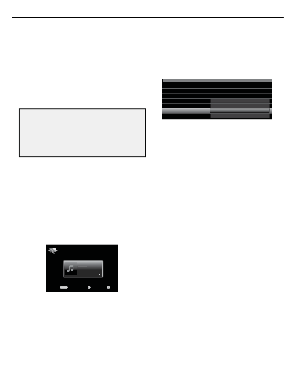
AVR 2650 harman/kardon
23
AVR
Listening to Media via Your Home Network
Your AVR can play MP3 and WMA audio media that is stored on a PC when both the
PC and the AVR are connected to your home network router.
MP3 compatibility: Mono or stereo, contstant bit rates (CBR) from 8kbps to
320kbps, variable bit rates (VBR) from lowest to highest quality, with sample rates
from 8kHz – 48kHz.
WMA compatibility: Ver. 9.2, stereo CBR with 32kHz – 48kHz sampling rate and
40kbps – 192kbps bit rate, mono CBR with 8kHz – 16kHz sampling rate and 5kbps –
16kbps bit rate, VBR Pass Encoding and Quality Encoding 10 – 98, 44kHz and 48kHz
sampling rate.
NOTES:
• A PC must be running Windows Media
Media Center version 2.0 or 3.0, or Intel® Media Server. We recommend that any
firewalls be turned off, although Windows Media Player may automatically make
any necessary adjustments to the firewall settings to allow media sharing.
• An Apple Macintosh computer must be running DLNA (Digital Living Network
Alliance)-compliant software. Examples of compatible software include the
TwonkyServer
Systems.
Before you can access files located on other devices via the network, each device
must first give permission to share files with the AVR:
To share media on PCs:
1. Open Windows Media Player.
2. Open the Library menu and select Media Sharing. The Media Sharing window will
appear.
3. Check the “Share My Media” box. An icon for the AVR will appear in the window.
4. Select the AVR icon, select “Allow,” then select “OK.”
The computer’s WMA and MP3 media should now be available to the AVR.
To share media on other types of computers, operating systems or media software:
Check the instructions for the computer, operating system or media player.
To listen to shared media, press the Network Source Selector button. (If Internet
Radio appears as the source, press the button a second time to switch from the
Internet Radio source to the Network source.) The Network screen will appear.
Press the Menu button, and the slide-in menu should list all devices that allow
sharing by name. Use the slide-in menu to browse the content stored in the device’s
media player library. Scroll to the desired item and press the OK button or the Right
button to select it. To return to the previous menu level (or to clear the menu from
view from the top level), press the Back/Exit button or the Left button.
NOTES:
• The Repeat settings are global for Network playback and USB playback. Changing
these settings for one of these sources will change the other source’s settings as
well.
• Although video content may appear in the menu, the AVR does not support video
playback from the network connection.
™
program by PacketVideo, and EyeConnect software by Elgato
Network
Menu: Previous: Next:
MENU
Selecting a Surround Mode
Selecting a surround mode can be as simple or sophisticated as your individual
system and tastes. Feel free to experiment, and you may find a few favorites for
32
®
Player version 11 or higher, Windows
Beanwater Junction
Jugalbandi
Night Crazy
01.50/3:55
Operating Your AVR
certain sources or program types. You can find more detailed information on surround
modes in Audio Processing and Surround Sound, on page 33.
To select a surround mode, press the Surround Modes button (front panel or remote).
The Surround Modes menu will appear.
Surround Modes – Cable/Sat
Auto Select – AVR Selects Best Mode
Virtual Surround – For Two Speaker Systems
Stereo:
Movie:
Music:
Video Game:
Press the Up/Down buttons repeatedly until the desired surround-mode category
appears: Auto Select, Virtual Surround, Stereo, Movie, Music or Video Game. Press
the OK button to change the surround-mode category.
Auto Select: For digital programs, such as a movie recorded with a Dolby Digital
or DTS soundtrack, the AVR will automatically use the soundtrack’s native surround
format. For two-channel analog and PCM programs, the AVR uses the Logic 7 Movie,
Logic 7 Music or Logic 7 Game mode, depending on the source.
Virtual Surround: When only two main speakers are present in the system, you can
use HARMAN Virtual Surround to create an enhanced soundfield that virtualizes the
missing speakers. Select between Wide and Reference modes.
Stereo: When you want two-channel playback, select the number of speakers you
want to use for playback:
• “2 CH Stereo” uses two speakers.
• “5 CH Stereo” plays the left-channel signal through the front left and surround
left speakers, the right-channel signal through the front right and surround right
speakers, and a summed mono signal through the center speaker.
• “7 CH Stereo” follows the same scheme as 5 CH Stereo but adds the surround
back left and surround back right speakers. This mode is available only when the
surround back speakers are present and have not been reassigned to multizone or
front height operation. See Audio Processing and Surround Sound, on page 33, for
more information.
Movie: Select from the following when you want a surround mode for movie
playback: Logic 7 Movie, DTS Neo:6 Cinema or Dolby Pro Logic II (IIx or IIz when
seven main speakers are present).
Music: Select from the following when you want a surround mode for music
playback: Logic 7 Music, DTS Neo:6 Music or Dolby Pro Logic II (IIx or IIz when seven
main speakers are present). The Dolby Pro Logic II/IIx/IIz Music mode allows access
to a submenu with some additional settings. See Audio Processing and Surround
Sound, on page 33, for more information.
Video Game: Select from the following when you want a surround mode for game
playback: Logic 7 Game or Dolby Pro Logic II (IIx/IIz when seven main speakers are
present) Game.
After you have made your selection, press the Back/Exit button.
See Audio Processing and Surround Sound, on page 33, for more information on
surround modes.
Audio Effects
The Audio Effects buttons on the front panel and remote provide settings that let you
adjust the Dolby Volume setting, tone controls, LFE trim, Equalization On/Off setting
or MP3 Enhancement to improve performance. We recommended that you leave
these settings at their default values until you are more familiar with your system.
See Audio Effects Button, on page 34, for complete information.
Video Modes
The Video Modes buttons on the front panel and remote provide settings that let you
use the AVR’s video processor to fine-tune the picture, if necessary, after making all
adjustments on the video display. We recommend that you leave the settings at their
defaults until you are completely familiar with the video performance of your system.
See Video Processing, on page 34, for complete information.
2 CH Stereo
Logic 7 Movie
Logic 7 Music
Logic 7 Game
Page 24

AVR 2650 harman/kardon
24
AVR
Symptom Cause Solution
Unit does not function when Main Power switch is
turned on
Front-panel Message display lights, but there’s no
sound or picture
No sound from any speaker; PROTECT message appears
on Message display
No sound from center or surround speakers • Incorrect surround mode
• No AC power
• Intermittent input connection
• Amplifier is in protection mode due to possible short
circuit
• Program material is monophonic
• Incorrect speaker configuration
• Program material is stereo
• Ensure that the power cord is plugged into a live
AC power outlet
• Check if the AC outlet is switch-controlled
• Dolby Digital EX
• Dolby Digital 2/2/.0 or .1, 3/2/.0 or .1
• Dolby Digital Plus via HDMI connection (source
device decodes to Dolby Digital when a coaxial
or optical connection is used)
• Select a surround mode other than stereo
• Mono programs contain no surround information
• Check the speaker configuration in the setup
menu
• The surround decoder may not create center- or
surround-channel information from nonencoded
programs
Troubleshooting
Unit does not respond to remote control commands • Weak batteries in remote
• AVR not selected
• Remote sensor is obscured
Intermittent buzzing in tuner • Local interference • Move the AVR or antenna away from computers,
(AVR 3650/AVR 365 only): Surround-back speaker
settings cannot be accessed, and the test tone does not
play through the surround back speakers
(AVR 3650/AVR 2650 only): The SIRIUS Preview
Channel (001) is silent
Unable to activate remote control Programming mode • Source Selector button is not held for at least 3
Remote buttons light, but AVR does not respond • Remote is in Zone 2 mode
• Multi-zone operation has been selected/Assigned AMP
channels have been assigned to Zone 2
• SIRIUS tuner is not connected
• SIRIUS antenna is in an improper location
• SIRIUS signal requires a refresh
seconds
• Change batteries in remote
• Press the Setup/AVR button
• Ensure that the AVR’s front-panel remote sensor
is in the line of sight of the remote
fluorescent lights, motors or other electrical
appliances
• Use the Speaker Setup menu to reassign the
Assigned AMP to the surround back left and right
channels
• Ensure that SIRIUS tuner is properly connected
• Re-locate the SIRIUS antenna according to
the recommendations in the SIRIUS tuner’s
instruction manual. For further help, visit
www.siriusradio.com
• Visit www.siriusradio.com
• Be sure to hold the Source Selector button for at
least 3 seconds
• Slide Zone Selector switch to the Zone 1 position.
Unable to establish network connection • AVR network programming requires rebooting • Cycle the AVR into the Standby mode, and then turn
it on again
Additional information on troubleshooting possible problems with your AVR and installation-related issues may be found in the list of “Frequently Asked
Questions,” which is located in the Product Support section of our Web site: www.harmankardon.com
43
Page 25

AVR 2650 harman/kardon
25
Resetting the Remote
To reset the remote to its factory-default condition, simultaneously press and hold any
Source Selector button and the “0” Number button. When the Program Indicator LED
flashes amber, enter the code “333.” When the green LED goes out, the remote control
will be reset.
Processor Reset
If the AVR behaves erratically after a power surge, first turn off the rear-panel Main
Power switch and unplug the AC power cord for at least 3 minutes. Plug the cord back
in and turn the AVR on. If this procedure doesn’t help, reset the AVR’s processor as
described below.
NOTE: A processor reset erases all user configurations, including video resolution,
speaker and level settings, and tuner presets. After a reset, reenter all of these settings
from your notes in the Appendix worksheets.
To reset the AVR’s processor:
1. Press the front-panel Standby/On switch to place the unit in the Standby mode (the
Power Indicator LED will turn amber).
2. Press and hold the front-panel OK button for at least 5 seconds until the
RESET message appears on the front-panel Message display.
NOTE: After performing a processor reset, wait at least 1 minute before pressing any
Source Selector buttons.
If the AVR does not function correctly after a processor reset, contact Harman/kardon at 1-800422-8027
Page 26

AVR 2650 harman/kardon
26
Page 27

AVR 2650 harman/kardon
27
S1
EXPLODED VIEW
51
S16
46-1
S9
43-1
48
55
55
50
45
43-2
S1
46-2
36
S14
S5
S1
35
49
S1
S15
S12
S1
27
S13
41-2
29
28
S1
43-3
24
S2
23
22
20
13
15
S1
S1
S1
39-2
S1
S3S3
18
39-1
18
S1
27
S1
26
25
30
42
S6
S8
12
10
17
S3S3
9
8
39-4
19
31
33
S1
39-3
S8
7
14
6
11
56
5
16
19
S1
S1
21
37
15
S1
S17
4
3
2
1
44
34
LARGER PARTS CHART
S5
S7
41-1
32
33
S6
54
53
S1
31
S1
32
DESCRIPTION PARTS NO. Q,ty
NO
S8
33
S1
SCREW
S2
SCREW
S3
S4
SCREW
S5
SCREW CTW3+8JR 4
S6
SCREW
S7
S8
SCREW,TRANS
S9
SCREW CHD1A012ZR 2
S10
SCREW
S11
SCREW CHD3A012R 5
S12
SCREW CHD4A012R 5
S13
S14
S15
S16
SCREW
S17
S8
33
CTB4+6FFZR
CTWS3+10GR
CTB3+6FFZR
CTW3+12JR
CTS3+8JFZRSCREW 4
CHD1A023R
CHD1A012R
CHD1A036FZRSCREW, SPECIAL 2
CHD1A036RSCREW, SPECIAL 4
CHD1A065RSCREW, SPECIAL 2
CTB3+8JR
NEXT PAGE
DESCRIPTION
NO
ORNAMENT,VOLUME CGU1A318Y 1
1
S1
CAP,VOLUME
2
HOLDER,VOLUME
3
INDICATOR,VOLUME
4
BADGE, HARMAN/KARDON
5
6
WINDOW , FIP
7
BADGE,AVR3650
8
FILTER , FIP
9
KNOB , STANDBY CBT2A1064 1
10
KNOB , TUNING CBT2A1065
11
PANEL , FRONT
12
INDICATOR , POWER CGL1A265Y
13
HOLDER , LED CMH2A215
14
PLATE , SHIELD CMC1A372 2
15
16
17
18
19
20
BRACKET , SIDE CMD2A443 1
21
BRACKET , SIDE L CMD1A555 1
22
RUBBER CHG1A309 1
23
CABINET,TOP
24
HEAT SINK
25
BRACKET,PCB
26
BRACKET H/S CMD1A674 2
27
BRACKET,FAN CMD1A694 1
28
CLAMPER , WIRE CHE36-3 1
29
CHASSIS,BOTTOM
30
31
FOOT A
32
FOOT B
33
CUSHION , FOOT CHG1A373 4
BRACKET,HDMI CMD1A786 1
34
BRACKET,FAN CMD1A506 1
35
PANEL,REAR CKF3A444Z 1
36
FRAME,BOTTOM CMD1A702 1
37
FRONT PCB ASS'Y
39
MAIN PCB ASS'Y COP12364D 1
41
DC-DC PCB ASS'Y COP12365D 11
42
43
POWER PCB ASS'Y 1
INPUT PCB ASS'Y
44
45
HDMI PCB ASS'Y COP12328D
46
VIDEO PCB ASS'Y 1
77CTB3+8JFZRSCREW
TRANS . POWER CLT5V058ZU 1
48
6
FAN , MOTOR CFNCF12825HSN 1
49
1
FAN , MOTOR CFNCF12625SA 1
50
INLET ASS'Y CJJ8A006ZWA 2
51
11
MOMS S/W ASS'Y CSH1A009ZVB 1
52
HOLDER,PCB CHE170 2
53
CUSHION CHG1A160Z 1
54
2
SUPPORT,PCB CRE1A076 2
55
COVER , USB CGR1A530H63 1
56
4
21
7
PARTS NO.
CGX1A338MBC63
CMH1A214
CGL1A222
CGB3A158Z
CGX4A390C66ZSHEET,AL FRONT 1
CGU2A410A25O
CGB1A233Z
CMZ1A127
CGW6A447RHUB24
CKC6B145S60
CMY4A314
CMD1A417
CUA4A294
CKL1A094
CKL1A095
COP12357D
FIP & KEY PCB
39-1
POWER LED PCB
39-2
VOLUME PCB
39-3
PHONE PCB
39-4
39-5
VIDEO PCB
39-6
COP12394D
POWER PCB A
43-1
POWER PCB B
43-2
GUIDE PCB(CARD CABLE)
43-3
COP12327D 1
COP12361D
VIDEO PCB
46-1
RS232 PCB
46-2
52
S5
S5
S1
Q,ty
REMARK
1
1
1
1
1
1
1
1
1
1
11
11
1
1
2
2PLATE , EARTH CMC2A338
1PLATE , EARTH(U&H) CMC1A414
2PLATE , EARTH(TOP) CMC1A416
1CMZ2A090SHEET, VOLUME 1
1SHEET , BLIND CPE1A009
1
1
2
1
2
2
1
1
1
1
1
1
1
1
1
1
1
1
1
1
Page 28

AVR 2650 harman/kardon
28
Page 29

AVR 2650 harman/kardon
2930313233343536373839404142434445
AMPLIFIER SECTION BIAS ADJUSTMENT
Measurement condition
.No input signal or volume position is minimum.
Standard value
.Ideal current = 48mA (± 5%)
.Ideal DC Voltage = 25.92mV (± 5%)
DC EVM
-
+
CN66 CN61 CN64 CN63 CN65 CN67CN62
VR8
DC VOLTMETER ; Connect to
CN66(SL),CN61(CEN),CN64(SR),CN63(FL),CN65(SBLPSju]YOmyPSju]^OziyP
NO.
1
2
3
4
5
6 Surround Back Left 25.92mV (± 5%)
VR8 VR8 VR8
Channel
Front Left
Front Right
Center
Surround Left
Surround Right
($03 PCB)
VR8 VR8VR8
Adjust for Adjustment
25.92mV (± 5%)
25.92mV (± 5%)
25.92mV (± 5%)
25.92mV (± 5%)
25.92mV (± 5%)
25.92mV (± 5%) Surround Back Right7
CN63
CN62
CN61
CN66
CN64
CN65
CN67
Page 30

Page 31

Page 32

Page 33
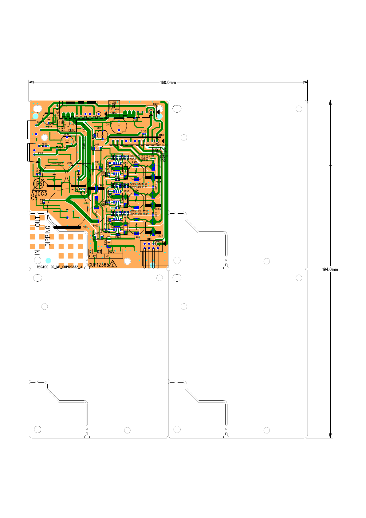
Page 34
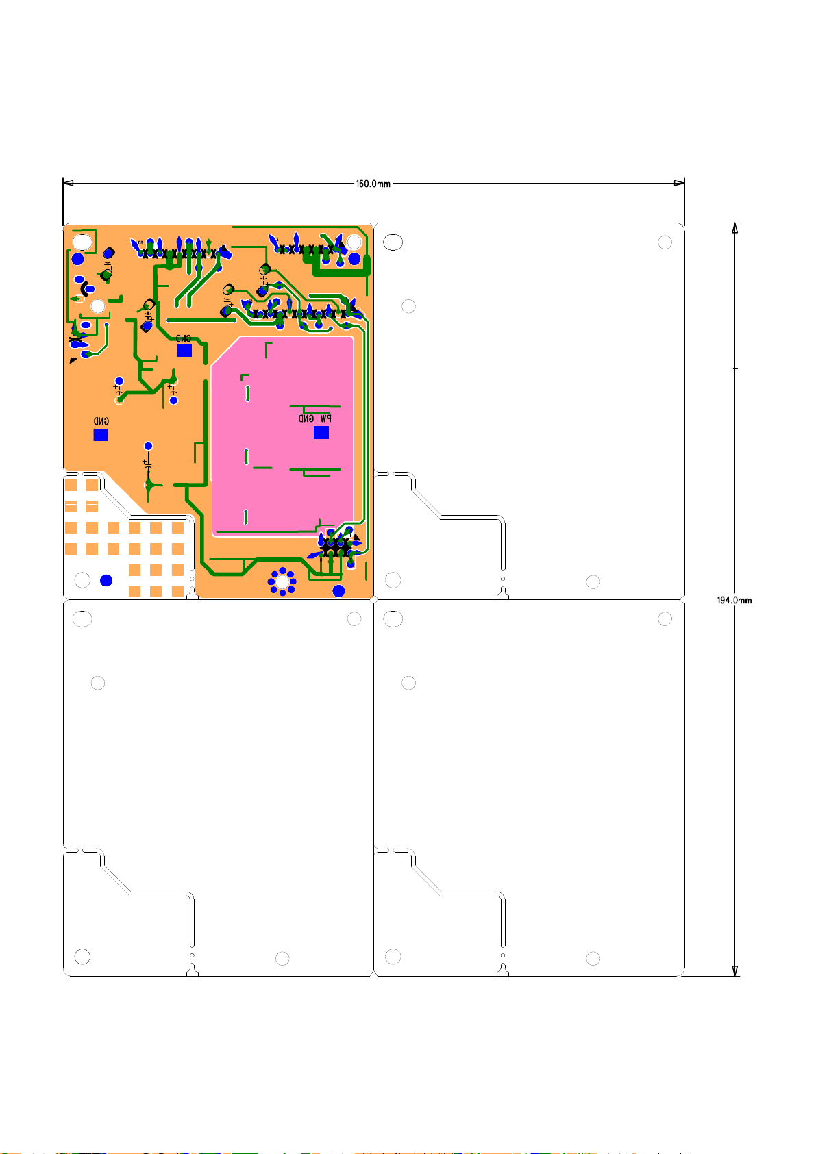
Page 35

Page 36

Page 37
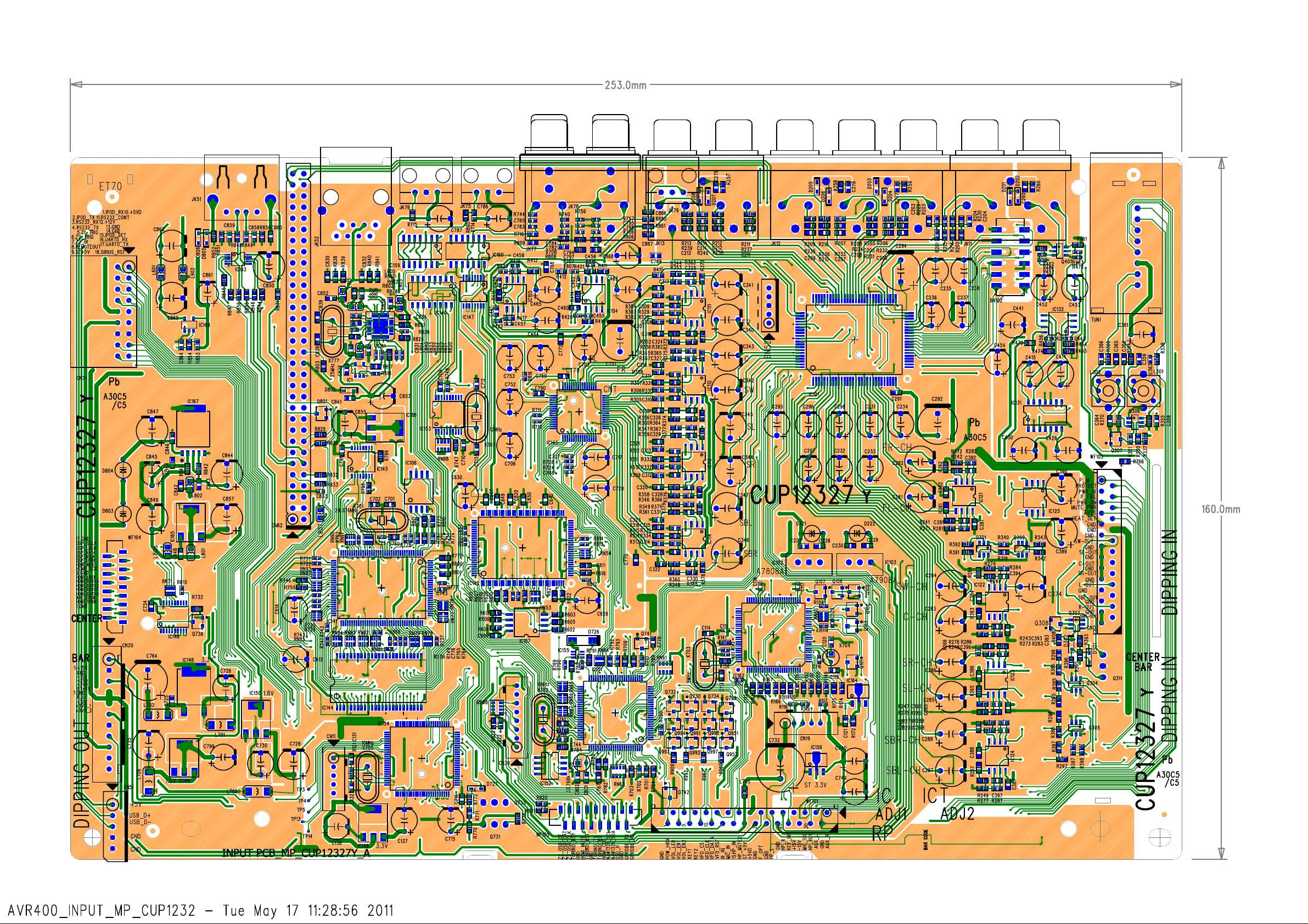
Page 38
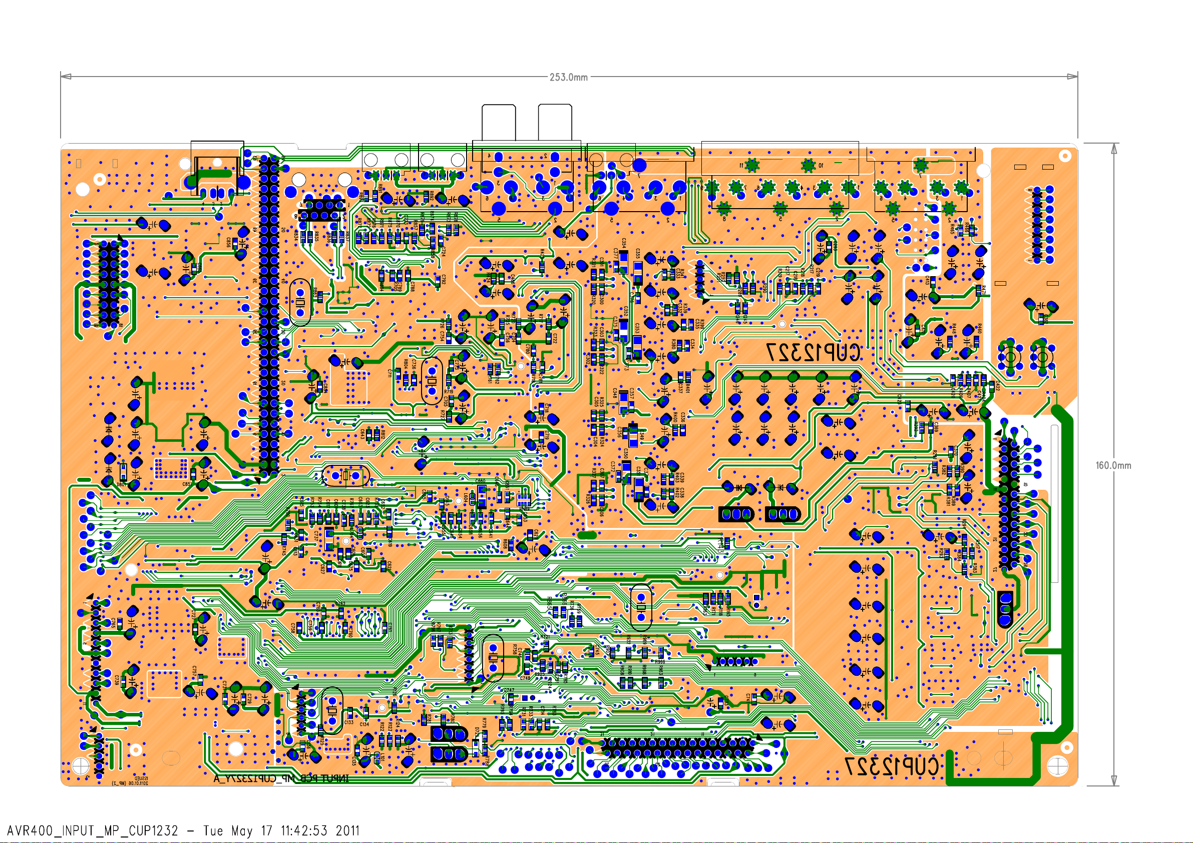
Page 39

Page 40
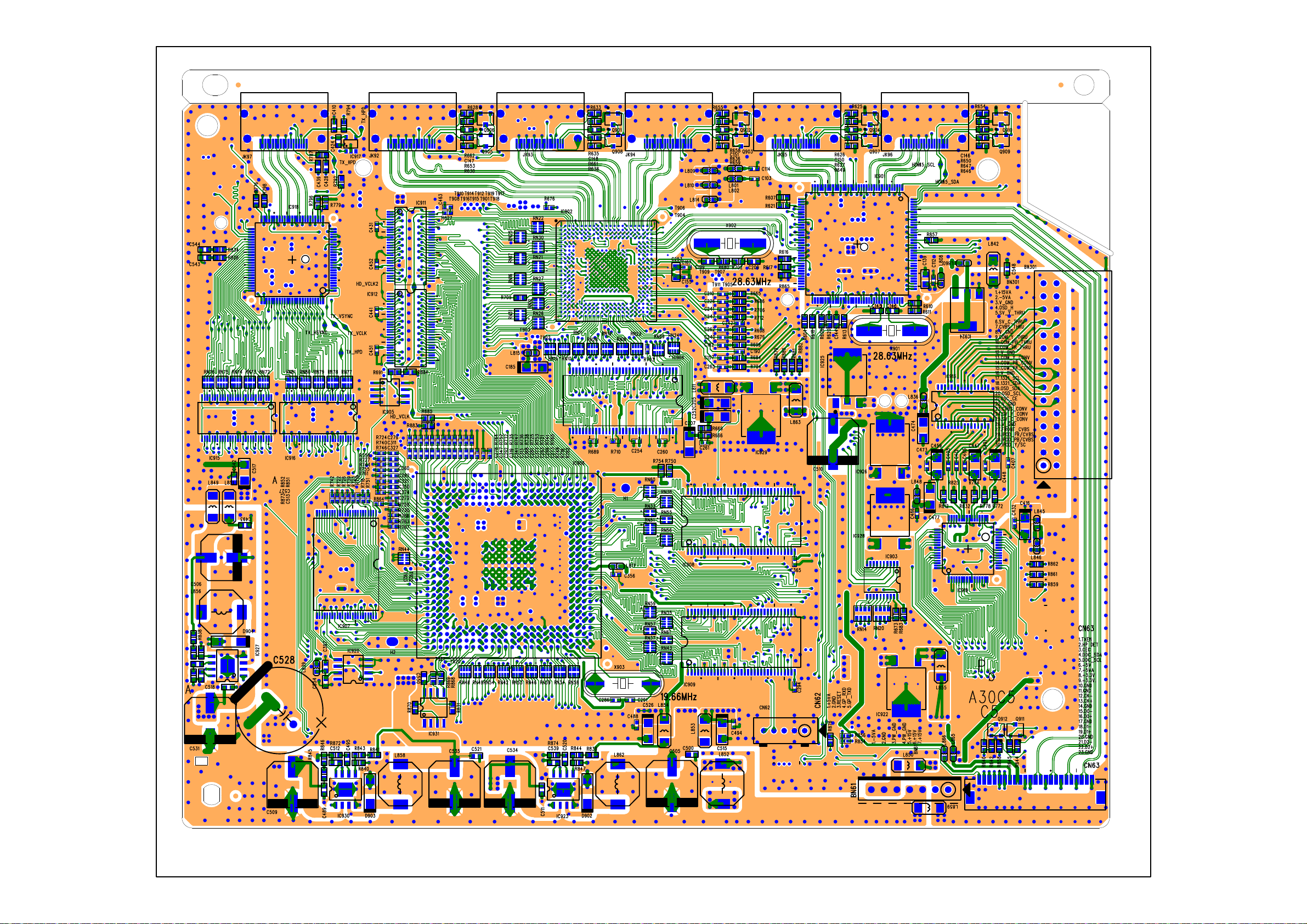
Page 41

Page 42

Page 43

Page 44

Page 45

Page 46

46
Page 47

AVR 2650 harman/kardon
47
AVR 2650 ELECTRICAL PARTS LIST
Quantity of all components with a designator = 1 unless otherwise noted
Reference Part Number Description
Designator
FRONT PCB ASS'Y CIP12357D
C121 CCBS1H151KBT CAP , CERAMIC(150PF/50V) CH UP025 B151K-A-B Z
C122 CCEA1AH331T CAP , ELECT(10V/330uF) KR3-10V331MB(6.3*11L)
C151 CCFT1H473ZF CAP , CERAMIC 0.047UF 50V Z
C152 CCEA1CKS100T CAP , ELECT(16V/10uF)-S KC3-16V100MA2(4*5L)
C161 CCBS1H104ZFT CAP , CERAMIC 0.1UF 50V Z
C171 CCBS1H104ZFT CAP , CERAMIC 0.1UF 50V Z
C181 CCBS1H104ZFT CAP , CERAMIC 0.1UF 50V Z
C213 CCBS1H223ZFT CAP , CERAMIC(22000PF/50V) CH UP025 F223Z-A-B J
C214 CCBS1H223ZFT CAP , CERAMIC(22000PF/50V) CH UP025 F223Z-A-B J
C252 CCEA1HKS2R2T CAP , ELECT(50V/2.2uF)-S KC3-50V2R2MA2(4*5L)
C311 CCBS1H102KBT CAP , CERAMIC(1000PF/50V) CH UP025 B102K-A-B Z
C322 CCBS1H102KBT CAP , CERAMIC(1000PF/50V) CH UP025 B102K-A-B Z
C412 CCBS1H103ZFT CAP , CERAMIC 0.01UF 50V Z
C413 CCEA1JH470TS CAP , ELECT 63V/47UF/105'C
C414 CCEA1JH470TS CAP , ELECT 63V/47UF/105'C
C415 CCBS1H103ZFT CAP , CERAMIC 0.01UF 50V Z
C422 CCEA1HH4R7T CAP , ELECT(50V/4.7uF) KR3-50V4R7MA(5*11L)
C431 CCBS1H104ZFT CAP , CERAMIC 0.1UF 50V Z
C441 CCBS1H223ZFT CAP , CERAMIC(22000PF/50V) CH UP025 F223Z-A-B J
C442 CCBS1H223ZFT CAP , CERAMIC(22000PF/50V) CH UP025 F223Z-A-B J
C550 CCBS1H560JT CAP , CERAMIC(56PF/50V) CH UP025SL560J-A-B Z
C555 CCBS1H560JT CAP , CERAMIC(56PF/50V) CH UP025SL560J-A-B Z
C556 CCEA1AH101T CAP , ELECT(10V/100uF) KR3-10V101MA(5*11L)
C557 CCBS1H103ZFT CAP , CERAMIC 0.01UF 50V Z
C558 CCBS1H103ZFT CAP , CERAMIC 0.01UF 50V Z
C631 CCBS1H104ZFT CAP , CERAMIC 0.1UF 50V Z
C651 CCBS1H104ZFT CAP , CERAMIC 0.1UF 50V Z
C652 CCBS1H471KBT CAP , CERAMIC(470PF/50V) CH UP025 B471K-A-B Z
C653 CCBS1H471KBT CAP , CERAMIC(470PF/50V) CH UP025 B471K-A-B Z
C714 CCBS1H223ZFT CAP , CERAMIC(22000PF/50V) CH UP025 F223Z-A-B J
C715 CCEA1CKS100T CAP , ELECT(16V/10uF)-S KC3-16V100MA2(4*5L)
C721 CCEA1HKS2R2T CAP , ELECT(50V/2.2uF)-S KC3-50V2R2MA2(4*5L)
C731 CCEA1AH471T CAP , ELECT(10V/470uF) KR3-10V471MB(6.3*11L)
C732 CCBS1H104ZFT CAP , CERAMIC 0.1UF 50V Z
C751 CCBS1C222MXT CAP , CERAMIC(2200PF/16V) CH EP025 B222M-A-B J
C752 CCBS1H102KBT CAP , CERAMIC(1000PF/50V) CH UP025 B102K-A-B Z
C753 CCBS1H102KBT CAP , CERAMIC(1000PF/50V) CH UP025 B102K-A-B Z
C754 CCBS1H104ZFT CAP , CERAMIC 0.1UF 50V Z
C801 CCEA1EH470T CAP , ELECT(25V/47uF) KR3-25V470MA(5*11L)
C802 CCEA1EH470T CAP , ELECT(25V/47uF) KR3-25V470MA(5*11L)
C811 CCEA1HH100T CAP , ELECT(50V/10uF) KR3-50V100MA(5*11L)
C813 CCBS1H470JT CAP , CERAMIC(47PF/50V) CH UP025SL470J-A-B Z
C821 CCBS1H471KBT CAP , CERAMIC(470PF/50V) CH UP025 B471K-A-B Z
C822 CCBS1H151KBT CAP , CERAMIC(150PF/50V) CH UP025 B151K-A-B Z
C823 CCEA1HH100T CAP , ELECT(50V/10uF) KR3-50V100MA(5*11L)
C830 CCBS1H473ZFT CAP , CERAMIC(47000PF/50V)CH UP025 F473Z-A-B J
C901 CCEA1HH100T CAP , ELECT(50V/10uF) KR3-50V100MA(5*11L)
C902 CCEA1HH100T CAP , ELECT(50V/10uF) KR3-50V100MA(5*11L)
C911 CCEA1EH470T CAP , ELECT(25V/47uF) KR3-25V470MA(5*11L)
C912 CCEA1EH470T CAP , ELECT(25V/47uF) KR3-25V470MA(5*11L)
Page 48

AVR 2650 harman/kardon
48
Reference Part Number Description
Designator
FRONT PCB ASS'Y CIP12357D
C923 CCBS1H681KBT CAP , CERAMIC(680PF/50V) CH UP025 B681K-A-B Z
C924 CCBS1H681KBT CAP , CERAMIC(680PF/50V) CH UP025 B681K-A-B Z
C931 CCEA1CH331T CAP , ELECT(16V/330uF) KR3-16V331MC(8*11.5L)
C932 CCEA1CH331T CAP , ELECT(16V/330uF) KR3-16V331MC(8*11.5L)
D161 HVD1N5819T DIODE , SCHOTTKY 1N5819
D204 HVD1SS133MT DIODE 1SS133T-77
D401 CVD1N4003ST DIODE , RECT 1N4003
D412 CVDZJ8.2BT DIODE , ZENER 8.2V ZJ8.2B 1/2W
D413 HVDMTZJ27BT DIODE , ZENER MTZJ27B 1/2W
D421 CVDZJ6.8BT DIODE , ZENER 6.8V ZJ6.8B 1/2W
D422 CVDZJ6.8BT DIODE , ZENER 6.8V ZJ6.8B 1/2W
D455 HVD1SS133MT DIODE 1SS133T-77
D631 HVD1SS133MT DIODE 1SS133T-77
D632 HVD1SS133MT DIODE 1SS133T-77
D714 C3A206 WIRE , COPPER SN95/PB5 , 0.6
L151 HLQ02C100KT COIL , AXAIL (10UH)
Q104 CVTKTC1027YT TRANSISTOR , KTC1027Y KTC1027Y/TO-92L/KEC
Q111 HVTKRA107MT TRANSISTOR , TO-92M KRA107M
Q112 HVTKRC107MT TRANSISTOR , TO-92M KRC107M
Q113 HVTKRC107MT TRANSISTOR , TO-92M KRC107M
Q251 HVTKTA1271YT TRANSISTOR KTA1271Y
Q252 HVTKRC107MT TRANSISTOR , TO-92M KRC107M
Q721 HVTKRC107MT TRANSISTOR , TO-92M KRC107M
Q906 HVTKRA107MT TRANSISTOR , TO-92M KRA107M
Q907 HVTKRA107MT TRANSISTOR , TO-92M KRA107M
Q941 HVTKTC2874BT TRANSISTOR , MUTE KTC2874B
Q942 HVTKTC2874BT TRANSISTOR , MUTE KTC2874B
Q943 HVTKTC2874BT TRANSISTOR , MUTE KTC2874B
Q944 HVTKTC2874BT TRANSISTOR , MUTE KTC2874B
Q951 HVTKRC107MT TRANSISTOR , TO-92M KRC107M
Q952 HVTKRA107MT TRANSISTOR , TO-92M KRA107M
Q954 HVTKRC107MT TRANSISTOR , TO-92M KRC107M
R101 CRD20TF2200T RES , CARBON(220 OHM, 1%)
R102 CRD20TF6800T RES , CARBON(680 OHM, 1%)
R103 CRD20TJ334T RES, CARBON(1/5W,330Kohm,J)
R113 CRD20TJ102T RES, CARBON(1/5W,1Kohm,J)
R201 CRD20TJ101T RES, CARBON(1/5W,100ohm,J)
R202 CRD20TJ101T RES, CARBON(1/5W,100ohm,J)
R203 CRD20TJ101T RES, CARBON(1/5W,100ohm,J)
R211 CRD20TJ101T RES, CARBON(1/5W,100ohm,J)
R213 CRD20TJ272T RES, CARBON(1/5W,2.7Kohm,J)
R214 CRD20TJ272T RES, CARBON(1/5W,2.7Kohm,J)
R251 CRD20TJ222T RES, CARBON(1/5W,2.2Kohm,J)
R252 CRD25TJ393T RES, CARBON(1/4W,39Kohm,J)
R312 CRD20TF1001T RES , CARBON 1K /1/5W /F
R313 CRD20TF1501T RES , CARBON 1.5K /1/5W /F
R314 CRD20TF1801T RES , CARBON 1.8K /1/5W /F
R315 CRD20TF2701T RES , CARBON 2.7K /1/5W/F
R316 CRD20TF3301T RES , CARBON 3.3K /1/5W/F
R322 CRD20TF1001T RES , CARBON 1K /1/5W /F
R323 CRD20TF1501T RES , CARBON 1.5K /1/5W /F
R324 CRD20TF1801T RES , CARBON 1.8K /1/5W /F
R325 CRD20TF2701T RES , CARBON 2.7K /1/5W/F
Page 49

,
)
m
1
m
AVR 2650 harman/kardon
49
Reference Part Number Description
Designator
FRONT PCB ASS'Y CIP12357D
R326 CRD20TF3301T RES , CARBON 3.3K /1/5W/F
R327 CRD20TF5601T RES , CARBON(5.6K/F)
R328 CRD20TF5601T RES , CARBON(5.6K/F)
R401 CRD25FJ3R3T RES , CARBON 3.3 OHM 1/4W J
R402 CRD25TJ4R7T RES, CARBON(1/4W,4.7ohm,J)
R403 CRD20TJ100T RES, CARBON(1/5W,10ohm,J)
R404 CRD25TJ4R7T RES, CARBON(1/4W,4.7ohm,J)
R411 CRD20TJ104T RES, CARBON(1/5W,100Kohm,J)
R412 CRD20TJ122T RES, CARBON(1/5W
R413 CRD20TJ104T RES, CARBON(1/5W,100Kohm,J)
R415 CRD20TJ473T RES, CARBON(1/5W,47Kohm,J)
R431 CRD20TJ100T RES, CARBON(1/5W,10ohm,J)
R432 CRD20TJ100T RES, CARBON(1/5W,10ohm,J)
R550 CRD20TJ100T RES, CARBON(1/5W,10ohm,J)
R555 CRD20TJ100T RES, CARBON(1/5W,10ohm,J)
R556 CRD20TJ153T RES, CARBON(1/5W,15Kohm,J)
R557 CRD20TJ153T RES, CARBON(1/5W,15Kohm,J)
R701 CRD20TJ102T RES, CARBON(1/5W,1Kohm,J)
R702 CRD20TJ102T RES, CARBON(1/5W,1Kohm,J)
R703 CRD20TJ102T RES, CARBON(1/5W,1Kohm,J)
R711 CRD20TJ470T RES, CARBON(1/5W,47ohm,J
R712 CRD20TJ470T RES, CARBON(1/5W,47ohm,J)
R713 CRD20TJ470T RES, CARBON(1/5W,47ohm,J)
R721 CRD20TJ103T RES, CARBON(1/5W,10Kohm,J)
R722 CRD20TJ101T RES, CARBON(1/5W,100oh
R731 CRD20TJ100T RES, CARBON(1/5W,10ohm,J)
R735 CRD20TJ152T RES, CARBON(1/5W,1.5Kohm,J)
R741 CRD20TJ123T RES, CARBON(1/5W,12Kohm,J)
R742 CRD20TJ102T RES, CARBON(1/5W,1Kohm,J)
R801 CRD20TJ101T RES, CARBON(1/5W,100ohm,J)
R802 CRD20TJ101T RES, CARBON(1/5W,100ohm,J)
R811 CRD20TJ104T RES, CARBON(1/5W,100Kohm,J)
R812 CRD20TJ102T RES, CARBON(1/5W,1Kohm,J)
R813 CRD20TJ103T RES, CARBON(1/5W,10Kohm,J)
R821 CRD20TJ102T RES, CARBON(1/5W,1Kohm,J)
R822 CRD20TJ103T RES, CARBON(1/5W,10Kohm,J)
R823 CRD20TJ104T RES, CARBON(1/5W,100Kohm,J)
R834 CRD20TJ222T RES, CARBON(1/5W,2.2Kohm,J)
R835 CRD20TJ103T RES, CARBON(1/5W,10Kohm,J)
R836 CRD20TJ152T RES, CARBON(1/5W,1.5Kohm,J)
R901 CRD25TJ101T RES, CARBON(1/4W,100ohm,J)
R902 CRD20TJ101T RES, CARBON(
R911 CRD20TJ101T RES, CARBON(1/5W,100ohm,J)
R912 CRD20TJ101T RES, CARBON(1/5W,100ohm,J)
R921 CRD20TJ102T RES, CARBON(1/5W,1Kohm,J)
R922 CRD20TJ102T RES, CARBON(1/5W,1Kohm,J)
R923 CRD20TJ152T RES, CARBON(1/5W,1.5Kohm,J)
R924 CRD20TJ152T RES, CARBON(1/5W,1.5Kohm,J)
R925 CRD20TJ104T RES, CARBON(1/5W,100Kohm,J)
R926 CRD20TJ104T RES, CARBON(1/5W,100Kohm,J)
R931 CRD20TJ104T RES, CARBON(1/5W,100Kohm,J)
R932 CRD20TJ104T RES, CARBON(1/5W,100Kohm,J)
R933 CRD20TJ221T RES, CARBON(1/5W,220oh
1.2Kohm,J)
,J)
/5W,100ohm,J)
,J)
Page 50

h
,
AVR 2650 harman/kardon
50
Reference Part Number Description
Designator
FRONT PCB ASS'Y CIP12357D
R934 CRD20TJ221T RES, CARBON(1/5W,220ohm,J)
R935 CRD20TJ221T RES, CARBON(1/5W,220ohm,J)
R936 CRD20TJ221T RES, CARBON(1/5W,220ohm,J)
R941 CRD25TJ432T RES, CARBON(1/4W,4.3Ko
R942 CRD20TJ472T RES, CARBON(1/5W,4.7Kohm,J)
R943 CRD20TJ472T RES, CARBON(1/5W,4.7Kohm,J)
R944 CRD20TJ472T RES, CARBON(1/5W,4.7Kohm,J)
R951 CRD20TJ102T RES, CARBON(1/5W,1Kohm,J)
R953 CRD20TJ362T RES, CARBON(1/5W,3.6Kohm,J)
R954 CRD20TJ103T RES, CARBON(1/5W,10Kohm,J)
S311 CST1A024ZT SW , TACT
S312 CST1A024ZT SW , TACT
S313 CST1A024ZT SW , TACT
S314 CST1A024ZT SW , TACT
S315 CST1A024ZT SW , TACT
S316 CST1A024ZT SW , TACT
S317 CST1A024ZT SW , TACT
S318 CST1A024ZT SW , TACT
S319 CST1A024ZT SW , TACT
S320 CST1A024ZT SW , TACT
S321 CST1A024ZT SW , TACT
S322 CST1A024ZT SW , TACT
S323 CST1A024ZT SW , TACT
S330 CST1A024ZT SW , TACT
BK71 CMD1A572 BRACKET , FIP
BK72 CMD1A572 BRACKET , FIP
BK73 CMD1A629 BRACKET
BN53 CWB1C005350BM001 Shield Wire ass'y
BN61 CJP06GB142ZB PIN HEADER(6P, 2.54mm)
BN73 CJP06GB142ZB PIN HEADER(6P, 2.54mm)
BN74 CWB1C005100BM WIRE ASS'Y(5P, 100MM)
CN61 CJP06GA221ZB FEMALE HEADER (6P,2.54mm)STRAIGHT TYPE FAS2851
CN71 CJP05GB03ZY WAFER,YMAW025(2.5mm,ANGLE)
CN72 CJP27GA285ZN WAFER,FPC 1.25mm,stright 1.25-2-NP
CN73 CJP06GB143ZB FEMALE HEADER(6P, 2.54mm)
CN74 CJP05GB03ZY WAFER,YMAW025(2.5mm,ANGLE)
C411 CCEA1JH101E CAP , ELECT 100UF 63V
D101 CVD1L0345W31BOCT201V L.E.D , WHITE CVD1L0345W31BOCT201
D102 CVD30ASOGCAA-S7 L.E.D , ORANGE T0L-30ASOGCAA-S7
D201 CVD1L0345W31BOCT201V L.E.D , WHITE CVD1L0345W31BOCT201
D202 CVD1L0345W31BOCT201V L.E.D , WHITE CVD1L0345W31BOCT201
D203 CVD1L0345W31BOCT201V L.E.D , WHITE CVD1L0345W31BOCT201
ET63 CMC2A325 PLATE , EARTH
FIP2 CFL162BD01GINK V.F.D 162-BD-01GINK
IC12 CRVKSM603TE5B SENSOR , REMOCON
IC13 CVISN74ACT04DR I.C , HEX INVERTERS(SOIC/D-14P)SN74ACT04DR TEXAS
IC14 HVINJM2068MDTE1 I.C , OP AMP (JRC) NJM2068MD-TE1
IC15 HVINJM4556AL I.C , HEADPHONE (JRC) NJM4556AL
JK53 CJJ9X009Z JACK, USB
JK63 CJJ2E026Z JACK, PHONES(6.35mm,SILVER) PJ-612A-51/YUQIU
RL91 CSL4A016ZU RELAY,BC3-12H,DC12V,2C2P BC3-12H/HANDOUK
VR74 CSR2A037Z ENCODER
CPE1A009 SHEET , BLIND
PCB
m,J)
Page 51

C
8
AVR 2650 harman/kardon
51
Reference Part Number Description
Designator
FRONT PCB ASS'Y CIP12357D
CTB3+10JR SCREW 27.0
CTWS3+10GR SCREW 2.0
CN72 CWC4C4A27B250B08 CARD , CABLE (27P/1.25mm,/250mm)
CGX1A338MBC63 CAP , VOLUME
CGX4A390C66Z SHEET , AL FRONT AVR2650
CKC6B145S60 CABINET , TOP
CMH1A214 HOLDER , VOLUME
CMZ2A090 SHEET , VOLUME
CTB3+8JFZR SCREW 17.0
CTB4+6FFZR SCREW 6.0
CUAAVR2650 BOTTOM CHASSIS ASS'Y
CFNRDM6025S MOTOR , FAN (60X60X25) 12V, 0.1A
CHD1A012ZR SCREW , SPECIAL 2.0
CHD1A023R SCREW , SPECIAL 4.0
CHD1A036FZR SCREW , SPECIAL 2.0
CHD1A065R SCREW , FLAT(2.6X4) 2.0
CHD4A012R SCREW , SPECIAL 4.0
CHE170 HOLDER , PCB 2.0
CHE36-3 CLAMPER , WIRE
CHG1A113 RUBBER 3.0
CHG1A160Z CUSHION , RUBBER
CHG1A373 CUSHION , FOOT 4.0
CHR301 CLAMPER 2.0
CKF3A444Z PANEL , REAR AVR2650
CKL1A094 FOOT , A 2.0
CKL1A095 FOOT , B 2.0
CMD1A506 BRACKET , FAN
CMD1A702 FRAME , BOTTOM
CMD1A786 BRACKET , HDMI
CNVFS2026-020021 MODULE,VENICE6.2 (NO DAB, NO WIFI)
INPUT PCB ASS'Y COP12327D
C133 CCUS1H104KC CAP, CHIP(1608, 50V/0.1uF)
C134 CCUS1H104KC CAP, CHIP(1608, 50V/0.1uF)
C135 CCUS1H104KC CAP, CHIP(1608, 50V/0.1uF)
C136 CCUS1H104KC CAP, CHIP(1608, 50V/0.1uF)
C217 CCUS1H101JA CAP,
C218 CCUS1H101JA CAP, CHIP(1608, 50V/100pF)
C219 CCUS1H101JA CAP, CHIP(1608, 50V/100pF)
C293 CCUS1H104KC CAP, CHIP(1608, 50V/0.1uF)
C300 CCUS1H272KC CAP, CHIP(1608, 50V/2700pF)
C301 CCUS1H272KC CAP, CHIP(1608, 50V/2700pF)
C302 CCUS1H683KC CAP, CHIP(1608, 50V/0.068uF)
C303 CCUS1H272KC CAP, CHIP(160
C304 CCUS1H272KC CAP, CHIP(1608, 50V/2700pF)
C305 CCUS1H272KC CAP, CHIP(1608, 50V/2700pF)
C306 CCUS1H272KC CAP, CHIP(1608, 50V/2700pF)
C307 CCUS1H272KC CAP, CHIP(1608, 50V/2700pF)
C332 CCUS1H103KC CAP, CHIP(1608, 50V/0.01uF)
C333 CCUS1H103KC CAP, CHIP(1608, 50V/0.01uF)
C334 CCUS1H103KC CAP, CHIP(1608, 50V/0.01uF)
C335 CCUS1H103KC CAP, CHIP(1608, 50V/0.01uF)
HIP(1608, 50V/100pF)
, 50V/2700pF)
Page 52

/
6
(
,
/
AVR 2650 harman/kardon
52
Reference Part Number Description
Designator
INPUT PCB ASS'Y COP12327D
C336 CCUS1H103KC CAP, CHIP(1608, 50V/0.01uF)
C337 CCUS1H103KC CAP, CHIP(1608, 50V/0.01uF)
C338 CCUS1H103KC CAP, CHIP(1608, 50V
C339 CCUS1H103KC CAP, CHIP(1608, 50V/0.01uF)
C356 CCUS1H104KC CAP, CHIP(1608, 50V/0.1uF)
C357 CCUS1H104KC CAP, CHIP(1608, 50V/0.1uF)
C362 CCUS1H223KC CAP, CHIP(1608, 50V/0.022uF)
C369 CCUS1H223KC CAP, CHIP(1
C370 CCUS1H223KC CAP, CHIP(1608, 50V/0.022uF)
C371 CCUS1H104KC CAP, CHIP(1608, 50V/0.1uF)
C372 CCUS1H104KC CAP, CHIP(1608, 50V/0.1uF)
C373 CCUS1H104KC CAP, CHIP(1608, 50V/0.1uF)
C375 CCUS1H104KC CAP, CHIP(1608, 50V/0.1uF)
C376 CCUS1H104KC CAP, CHIP(1608, 50V/0.1uF)
C377 CCUS1H104KC CAP, CHIP(1608, 50V/0.1uF)
C412 CCUS1H104KC CAP, CHIP(1608, 50V/0.1uF)
C413 CCUS1H104KC CAP, CHIP(1608, 50V/0.1uF)
C420 CCUS1H151JA CAP, CHIP(1608, 50V/150pF)
C421 CCUS1H151JA CAP, CHIP(1608, 50V/150pF)
C422 CCUS1H104KC CAP, CHIP(1608, 50V/0.1uF)
C423 CCUS1H104KC CAP, CHIP(1608, 50V/0.1uF)
C466 CCUS1H104KC CAP, CHIP(1608, 50V/0.1uF)
C601 CCUS1H104KC CAP, CHIP(1608, 50V/0.1uF)
C603 CCUS1H104KC CAP, CHIP(1608, 50V/0.1uF)
C605 CCUS1H104KC CAP, CHIP(1608, 50V/0.1uF)
C607 CCUS1H104KC CAP, CHIP(1608, 50V/0.1uF)
C609 CCUS1H104KC CAP, CHIP(1608, 50V/0.1uF)
C611 CCUS1H104KC CAP, CHIP(1608, 50V/0.1uF)
C613 CCUS1H104KC CAP, CHIP(1608, 50V/0.1uF)
C615 CCUS1H104KC CAP, CHIP(1608, 50V/0.1uF)
C617 CCUS1H104KC CAP, CHIP(1608, 50V/0.1uF)
C619 CCUS1H104KC CAP, CHIP
C621 CCUS1H104KC CAP, CHIP(1608, 50V/0.1uF)
C623 CCUS1H104KC CAP, CHIP(1608, 50V/0.1uF)
C625 CCUS1H104KC CAP, CHIP(1608, 50V/0.1uF)
C627 CCUS1H104KC CAP, CHIP(1608, 50V/0.1uF)
C629 CCUS1H104KC CAP, CHIP(1608, 50V/0.1uF)
C631 CCUS1H104KC CAP, CHIP(1608, 50V/0.1uF)
C641 CCUS1H104KC CAP, CHIP(1608
C643 CCUS1H104KC CAP, CHIP(1608, 50V/0.1uF)
C644 CCUS1H104KC CAP, CHIP(1608, 50V/0.1uF)
C645 CCUS1H104KC CAP, CHIP(1608, 50V/0.1uF)
C646 CCUS1H104KC CAP, CHIP(1608, 50V/0.1uF)
C648 CCUS1H104KC CAP, CHIP(1608, 50V/0.1uF)
C651 CCUS1H104KC CAP, CHIP(1608, 50V/0.1uF)
C652 CCUS1H104KC CAP, CHIP(1608, 50V
C653 CCUS1H104KC CAP, CHIP(1608, 50V/0.1uF)
C654 CCUS1H104KC CAP, CHIP(1608, 50V/0.1uF)
C655 CCUS1H104KC CAP, CHIP(1608, 50V/0.1uF)
C656 CCUS1H104KC CAP, CHIP(1608, 50V/0.1uF)
C658 CCUS1H104KC CAP, CHIP(1608, 50V/0.1uF)
C660 CCSNA0J220B CAP , CHIP TANTAL(22uF/6.3V, NingXia XingRi)
C704 CCUS1H104KC CAP, CHIP(1608, 50V/0.1uF)
08, 50V/0.022uF)
1608, 50V/0.1uF)
50V/0.1uF)
0.01uF)
0.1uF)
Page 53

C
/
AVR 2650 harman/kardon
53
Reference Part Number Description
Designator
INPUT PCB ASS'Y COP12327D
C705 CCUS1H104KC CAP, CHIP(1608, 50V/0.1uF)
C714 CCUS1H104KC CAP, CHIP(1608, 50V/0.1uF)
C718 CCUS1H104KC CAP, CHIP(1608, 50V/0.1uF)
C719 CCUS1H104KC CAP, CHIP(1608, 50V/0.1uF)
C722 CCUS1H104KC CAP, CHIP(1608, 50V/0.1uF)
C723 CCUS1H104KC CAP, CHIP(1608, 50V/0.1uF)
C727 CCUS1H104KC CAP, CHIP(1608, 50V/0.1uF)
C729 CCUS1H104KC CAP, CHIP(1608, 50V/0.1uF)
C731 CCUS1H104KC CAP, CHIP(1608, 50V/0.1uF)
C733 CCUS1H104KC CAP, CHIP(1608, 50V/0.1uF)
C737 CCSNA0J220B CAP , CHIP TANTAL(22uF/6.3V, NingXia XingRi)
C738 CCUS1H104KC CAP, CHIP(1608, 50V/0.1uF)
C739 CCUS1H104KC CAP, CHIP(1608, 50V/0.1uF)
C741 CCUS1H104KC CAP, CHIP(1608, 50V/0.1uF)
C745 CCUS1H104KC CAP, CHIP(1608, 50V/0.1uF)
C746 CCUS1H104KC CAP, CHIP(1608, 50V/0.1uF)
C747 CCUS1H104KC CAP, CHIP(1608, 50V/0.1uF)
C748 CCUS1H104KC CAP, CHIP(1608, 50V/0.1uF)
C751 CCUS1H104KC CAP, CHIP(1608, 50V/0.1uF)
C754 CCUS1H104KC CAP, CHIP(1608, 50V/0.1uF)
C756 CCUS1H104KC CAP, CHIP(1608, 50V/0.1uF)
C757 CCUS1H104KC CAP, CHIP(1608, 50V/0.1uF)
C758 CCUS1H104KC CAP, CHIP(1608, 50V/0.1uF)
C759 CCUS1H104KC CAP, CHIP(1608, 50V/0.1uF)
C760 CCUS1H104KC CAP, CHIP(1608, 50V/0.1uF)
C761 CCUS1H104KC CAP, CHIP(1608, 50V/0.1uF)
C762 CCUS1H104KC CAP, CHIP(1608, 50V/0.1uF)
C763 CCUS1H104KC CAP,
C765 CCUS1H104KC CAP, CHIP(1608, 50V/0.1uF)
C773 CCUS1H104KC CAP, CHIP(1608, 50V/0.1uF)
C780 CCUS1H102KC CAP, CHIP(1608, 50V/1000pF)
C781 CCUS1H223KC CAP, CHIP(1608, 50V/0.022uF)
C788 CCUS1H104KC CAP, CHIP(1608, 50V/0.1uF)
C789 CCUS1H103KC CAP, CHIP(1608, 50V/0.01uF)
C792 CCUS1H104KC CAP, CHIP(1608, 50V
C865 CCUS1H104KC CAP, CHIP(1608, 50V/0.1uF)
L101 CLZ9R005Z FERRITE CHIP BEAD(1608/60ohm)HCB1608KF-600T30/COILMASTER
L604 CLZ9R005Z FERRITE CHIP BEAD(1608/60ohm)HCB1608KF-600T30/COILMASTER
L704 CLZ9R005Z FERRITE CHIP BEAD(1608/60ohm)HCB1608KF-600T30/COILMASTER
RN89 CRJ104DJ103T RES , CHIP , 10K OHM, 5% , 1608 X 4 10K(1608)
R118 CRJ10DJ104T RES, CHIP(1608/5%/100Kohm)
R122 CRJ10DJ473T RES, CHIP(1608/5%/47Kohm)
R123 CRJ10DJ473T RES, CHIP(1608/5%/47Kohm)
R124 CRJ10DJ473T RES, CHIP(1608/5%/47Kohm)
R125 CRJ10DJ473T RES, CHIP(1608/5%/47Kohm)
R126 CRJ10DJ332T RES, CHIP(1608/5%/3.3Kohm)
R163 CRJ10DJ104T RES, CHIP(1608/5%/100Kohm)
R165 CRJ10DJ104T RES, CHIP(1608/5%/100Kohm)
R171 CRJ10DJ0R0T RES, CHIP(1608/5%/0ohm)
R217 CRJ10DJ101T RES, CHIP(1608/5%/100ohm)
R218 CRJ10DJ101T RES, CHIP(1608/5%/100ohm)
R219 CRJ10DJ101T RES, CHIP(1608/5%/100ohm)
R289 CRJ10DJ104T RES, CHIP(1608/5%/100Kohm)
HIP(1608, 50V/0.1uF)
0.1uF)
Page 54

K
.
/
)
0
AVR 2650 harman/kardon
54
Reference Part Number Description
Designator
INPUT PCB ASS'Y COP12327D
R290 CRJ10DJ104T RES, CHIP(1608/5%/100Kohm)
R291 CRJ10DJ563T RES, CHIP(1608/5%/56Kohm)
R292 CRJ10DJ563T RES, CHIP(1608/5%/56Kohm)
R293 CRJ10DJ563T RES, CHIP(1608/5%/56
R294 CRJ10DJ563T RES, CHIP(1608/5%/56Kohm)
R317 CRJ10DJ561T RES, CHIP(1608/5%/560ohm)
R320 CRJ10DJ682T RES, CHIP(1608/5%/6.8Kohm)
R321 CRJ10DJ682T RES, CHIP(1608/5%/6
R322 CRJ10DJ103T RES, CHIP(1608/5%/10Kohm)
R323 CRJ10DJ682T RES, CHIP(1608/5%/6.8Kohm)
R324 CRJ10DJ682T RES, CHIP(1608/5%/6.8Kohm)
R325 CRJ10DJ682T RES, CHIP(1608/5%/6.8Kohm)
R326 CRJ10DJ682T RES, CHIP(1608/5%
R327 CRJ10DJ682T RES, CHIP(1608/5%/6.8Kohm)
R339 CRJ10DJ104T RES, CHIP(1608/5%/100Kohm)
R341 CRJ10DJ104T RES, CHIP(1608/5%/100Kohm)
R380 CRJ10DJ104T RES, CHIP(1608/5%/100Kohm)
R381 CRJ10DJ561T RES, CHIP(1608/5%/560ohm
R382 CRJ10DJ561T RES, CHIP(1608/5%/560ohm)
R383 CRJ10DJ561T RES, CHIP(1608/5%/560ohm)
R384 CRJ10DJ561T RES, CHIP(1608/5%/560ohm)
R389 CRJ10DJ563T RES, CHIP(1608/5%/56Kohm)
R390 CRJ10DJ563T RES, CHIP(1608/5%/56Kohm)
R399 CRJ10DJ104T RES, CHIP(1608/5%/100Kohm)
R400 CRJ10DJ104T RES, CHIP(1608/5%/100Kohm)
R401 CRJ10DJ104T RES, CHIP(1608/5%/100Kohm)
R402 CRJ10DJ104T RES, CHIP(1608/5%/100Kohm)
R403 CRJ10DJ104T RES, CHIP(1608/5%/100Kohm)
R404 CRJ10DJ182T RES, CHIP(1608/5%/1.8Kohm)
R406 CRJ10DJ101T RES, CHIP(1608/5%/100ohm)
R407 CRJ10DJ101T RES, CHIP(1608/5%/100ohm)
R424 CRJ10DJ472T RES, CHIP(1608/5%/4.7Kohm)
R425 CRJ10DJ392T RES, CHIP(1608/5%/3.9Kohm)
R448 CRJ10DJ104T RES, CHIP(1608/5%/100Kohm)
R460 CRJ10DJ104T RES, CHIP(1608/5%/100Kohm)
R465 CRJ10DJ472T RES, CHIP(1608/5%/4.7Kohm)
R466 CRJ10DJ472T RES, CHIP(1608/5%/4.7Kohm)
R471 CRJ10DJ101T RES, CHIP(1608/5%/100ohm)
R700 CRJ10DJ103T RES, CHIP(1608/5%/10Kohm)
R713 CRJ10DJ103T RES, CHIP(1608/5%/10Kohm)
R717 CRJ10DJ0R0T RES, CHIP(1608/5%/0ohm)
R718 CRJ10DF1371T RES, CHIP(1608/1%/1.37Kohm)
R719 CRJ10DJ0R0T RES, CHIP(16
R720 CRJ10DJ0R0T RES, CHIP(1608/5%/0ohm)
R721 CRJ10DJ472T RES, CHIP(1608/5%/4.7Kohm)
R725 CRJ10DJ0R0T RES, CHIP(1608/5%/0ohm)
R726 CRJ10DJ100T RES, CHIP(1608/5%/10ohm)
R727 CRJ10DJ0R0T RES, CHIP(1608/5%/0ohm)
R733 CRJ10DJ0R0T RES, CHIP(1608/5%/0ohm)
R735 CRJ10DJ103T RES, CHIP(1608/5%/10Kohm)
R745 CRJ10DJ103T RES, CHIP(1608/5%/10Kohm)
R753 CRJ10DJ332T RES, CHIP(1608/5%/3.3Kohm)
R754 CRJ10DJ332T RES, CHIP(1608/5%/3.3Kohm)
8/5%/0ohm)
ohm)
8Kohm)
6.8Kohm)
Page 55

0
C
1
1
C
AVR 2650 harman/kardon
55
Reference Part Number Description
Designator
INPUT PCB ASS'Y COP12327D
R759 CRJ10DJ0R0T RES, CHIP(1608/5%/0ohm)
R761 CRJ10DJ102T RES, CHIP(1608/5%/1Kohm)
R762 CRJ10DJ102T RES, CHIP(1608/5%/1Kohm)
R763 CRJ10DJ103T RES, CHIP(1608/5%/10Kohm)
R767 CRJ10DF5101T RES, CHIP(1608/1%/5.1Kohm)
R785 CRJ10DJ104T RES, CHIP(1608/5%/100Kohm)
R788 CRJ10DJ0R0T RES, CHIP(1608/5%/0ohm)
R795 CRJ10DJ0R0T RES, CHIP(1608/5%/0ohm)
R797 CRJ10DJ0R0T RES, CHIP(1608/5%/0ohm)
R812 CRJ10DJ103T RES, CHIP(1608/5%/10Kohm)
R834 CRJ10DJ0R0T RES, CHIP(1608/5%/
R835 CRJ10DJ0R0T RES, CHIP(1608/5%/0ohm)
R836 CRJ10DJ0R0T RES, CHIP(1608/5%/0ohm)
R837 CRJ10DJ0R0T RES, CHIP(1608/5%/0ohm)
R857 CRJ10DJ0R0T RES, CHIP(1608/5%/0ohm)
R858 CRJ10DJ0R0T RES,
R863 CRJ10DJ103T RES, CHIP(1608/5%/10Kohm)
R866 CRJ10DJ0R0T RES, CHIP(1608/5%/0ohm)
R870 CRJ10DJ473T RES, CHIP(1608/5%/47Kohm)
R871 CRJ10DJ473T RES, CHIP(1608/5%/47Kohm)
R872 CRJ10DJ473T RES, CHIP(1608/5%/47Kohm)
R877 CRJ10DJ472T RES, CHIP(1608/5%/4.7Kohm)
R891 CRJ10DJ0R0T RES, CHIP(1608/5%/0ohm)
R907 CRJ10DJ103T RES, CHIP(1608/5%/10Kohm)
R908 CRJ10DJ105T RES, CHIP(1608/5%/1Mohm)
R910 CRJ10DJ105T RES, CHIP(1608/5%/1Mohm)
R925 CRJ10DJ0R0T RES, CHIP(1608/5%/0ohm)
R932 CRJ10DJ103T RES, CHIP(1608/5%/10Kohm)
R963 CRJ10DJ105T RES, CHIP(1608/5%/1Mohm)
R966 CRJ10DJ472T RES, CHIP(1608/5%/4.7Kohm)
R968 CRJ10DJ105T RES, CHIP(1608/5%/1Mohm)
R969 CRJ10DJ103T RES, CHIP(1608/5%/10Kohm)
C111 CCUI1C104KC CAP , CHIP (
C112 CCUI1C104KC CAP , CHIP (1005, 16V/0.1uF)
C113 CCUS1H180JA CAP, CHIP(1608, 50V/18pF)
C114 CCUS1H180JA CAP, CHIP(1608, 50V/18pF)
C115 CCUI1C104KC CAP , CHIP (1005, 16V/0.1uF)
C116 CCUI1C104KC CAP , CHIP (1005, 16V/0.1uF)
C117 CCUI1C104KC CAP , CHIP (1005, 16V/0.1uF)
C118 CCUI1C104KC CAP , CHIP (1005,
C121 CCUS1H104KC CAP, CHIP(1608, 50V/0.1uF)
C123 CRJ06IJ183T RES, CHIP(1005/5%/18Kohm)
C131 CCUS1H150JA CAP, CHIP(1608, 50V/15pF)
C132 CCUS1H150JA CAP, CHIP(1608, 50V/15pF)
C203 CCUS1H221JA CAP,
C204 CCUS1H221JA CAP, CHIP(1608, 50V/220pF)
C205 CCUS1H221JA CAP, CHIP(1608, 50V/220pF)
C206 CCUS1H221JA CAP, CHIP(1608, 50V/220pF)
C207 CCUS1H221JA CAP, CHIP(1608, 50V/220pF)
C208 CCUS1H221JA CAP, CHIP(1608, 50V/220pF)
C209 CCUS1H221JA CAP, CHIP(1608, 50V/220pF)
C210 CCUS1H221JA CAP, CHIP(1608, 50V/220pF)
C227 CCUS1H104KC CAP, CHIP(1608, 50V/0.1uF)
HIP(1608/5%/0ohm)
005, 16V/0.1uF)
HIP(1608, 50V/220pF)
ohm)
6V/0.1uF)
Page 56

0
C
P
u
/
AVR 2650 harman/kardon
56
Reference Part Number Description
Designator
INPUT PCB ASS'Y COP12327D
C228 CCUS1H104KC CAP, CHIP(1608, 50V/0.1uF)
C229 CCUS1H104KC CAP, CHIP(1608, 50V/0.1uF)
C230 CCUS1H104KC CAP, CHIP(1608, 50V/0.1uF)
C260 CCUS1H104KC CAP, CHIP(1608, 50V/0.1uF)
C277 CCUS1H104KC CAP, CHIP(1608, 50V/0.1uF)
C278 CCUS1H104KC CAP, CHIP(1608, 50V/0.1uF)
C291 CCUS1H104KC CAP, CHIP(1608, 50V/0.1uF)
C308 CCUS1H391JA CAP, CHIP(1608, 50V/390pF)
C309 CCUS1H391JA CAP, CHIP(1608, 50V/390pF)
C310 CCUS1H822KC CAP, CHIP(1608, 50V/8200pF)
C311 CCUS1H391JA CAP, CHIP(1608, 50V/390pF)
C312 CCUS1H391JA CAP, CHIP(1608, 50V/390pF)
C313 CCUS1H391JA CAP, CHIP(1608, 5
C314 CCUS1H391JA CAP, CHIP(1608, 50V/390pF)
C315 CCUS1H391JA CAP, CHIP(1608, 50V/390pF)
C316 CCUS1H272KC CAP, CHIP(1608, 50V/2700pF)
C317 CCUS1H272KC CAP, CHIP(1608, 50V/2700pF)
C318 CCUS1H683KC CAP,
C319 CCUS1H272KC CAP, CHIP(1608, 50V/2700pF)
C320 CCUS1H272KC CAP, CHIP(1608, 50V/2700pF)
C321 CCUS1H272KC CAP, CHIP(1608, 50V/2700pF)
C322 CCUS1H272KC CAP, CHIP(1608, 50V/2700pF)
C323 CCUS1H272KC CAP, CHIP(1608, 50V/2700pF)
C324 CCUS1H391JA CAP, CHIP(1608, 50V/390pF)
C325 CCUS1H391JA CAP, CHIP(1608, 50V/390pF)
C326 CCUS1H822KC CAP, CHIP(1608, 50V/8200pF)
C327 CCUS1H391JA CAP, CHIP(1608, 50V/390pF)
C328 CCUS1H391JA CAP, CHIP(1608, 50V/390pF)
C329 CCUS1H391JA CAP, CHIP(1608, 50V/390pF)
C330 CCUS1H391JA CAP, CHIP(1608, 50V/390pF)
C331 CCUS1H391JA CAP, CHIP(1608, 50V/390pF)
C358 CCUS1H392KC CAP, CHIP(1608, 50V/3900pF)
C359 CCUS1H822KC CAP, CHIP(1608, 50V/8200pF)
C363 CCUI1E103KC CAP, CHIP(1005, 25V/0.01uF)
C364 CCUS1H392KC CAP, CHIP(1608, 50V/3900pF)
C365 CCUS1H822KC CAP, CHIP(1608, 50V/8200pF)
C383 CCUS1H223KC CAP, CHIP(1608, 50V/0.022uF)
C384 CCUS1H223KC CAP, CHI
C385 CCUS1H223KC CAP, CHIP(1608, 50V/0.022uF)
C386 CCUS1H223KC CAP, CHIP(1608, 50V/0.022uF)
C387 CCUS1H223KC CAP, CHIP(1608, 50V/0.022uF)
C388 CCUS1H223KC CAP, CHIP(1608, 50V/0.022
C394 CCUS1H102KC CAP, CHIP(1608, 50V/1000pF)
C428 CCUI1H151JA CAP, CHIP(1005, 50V/150pF)
C442 CCUI1H151JA CAP, CHIP(1005, 50V/150pF)
C455 CCUI1H101JA CAP, CHIP(1005, 50V/100pF)
C456 CCUI1H151JA CAP, CHIP(1005, 50V/150pF)
C457 CCUI1H101JA CAP, CHIP(1005, 50V/100pF)
C458 CCUI1H151JA CAP, CHIP(1005, 50V/150pF)
C459 CCUI1C104KC CAP , CHIP (1005, 16V/0.1uF)
C460 CCUS1H272KC CAP, CHIP(1608, 50V/2700pF)
C461 CCUS1H272KC CAP, CHIP(1608, 50V
C462 CCUI1C104KC CAP , CHIP (1005, 16V/0.1uF)
HIP(1608, 50V/0.068uF)
(1608, 50V/0.022uF)
V/390pF)
F)
2700pF)
Page 57

(
C
0
AVR 2650 harman/kardon
57
Reference Part Number Description
Designator
INPUT PCB ASS'Y COP12327D
C610 CCUI1H150JA CAP, CHIP(1005, 50V/15pF)
C642 CCUS1H104KC CAP, CHIP(1608, 50V/0.1uF)
C647 CCUS1H104KC CAP, CHIP(1608, 50V/0.1uF)
C649 CCUS1H104KC CAP, CHIP(1608, 50V/0.1uF)
C650 CCUS1H104KC CAP, CHIP(1608, 50V/0.1uF)
C657 CCUI1C104KC CAP , CHIP (1005, 16V/0.1uF)
C659 CCUS1H104KC CAP, CHIP(1608, 50V/0.1uF)
C701 CCUS1H150JA CAP, CHIP(1608, 50V/15pF)
C702 CCUS1H150JA CAP, CHIP
C707 CCUI1H102KC CAP, CHIP(1005, 50V/1000pF)
C708 CCUI1C104KC CAP , CHIP (1005, 16V/0.1uF)
C725 CCUS1H104KC CAP, CHIP(1608, 50V/0.1uF)
C734 CCUS1H104KC CAP, CHIP(1608, 50V/0.1uF)
C742 CCUS1H300JA CAP, CHIP(1608, 50V/30pF)
C743 CCUI1C104KC CAP , CHIP (1005, 16V/0.1uF)
C744 CCUS1H330JA CAP, CHIP(1608, 50V/33pF)
C767 CCUS1A105KC CAP, CHIP(1608, 10V/1uF)
C768 CCUS1H104KC CAP, CHIP(1608, 50V/0.1uF)
C769 CCUS1H104KC CAP, CHIP(1608, 50V/0.1uF)
C770 CCUS1H104KC CAP, CHIP(1608, 50V/0.1uF)
C772 CCUS1H104KC CAP, CHIP(1608, 50V/0.1uF)
C776 CCUI1H150JA CAP, CHIP(1005, 50V/15pF)
C778 CCUS1H104KC CAP, CHIP(1608, 50V/0.1uF)
C790 CCUS1H103KC CAP,
C791 CCUS1H104KC CAP, CHIP(1608, 50V/0.1uF)
C794 CCUI1H181JA CAP, CHIP(1005, 50V/180pF)
C795 CCUI1H181JA CAP, CHIP(1005, 50V/180pF)
C797 CCUI1C104KC CAP , CHIP (1005, 16V/0.1uF)
C798 CCUI1C104KC CAP , CHIP (1005, 16V/
C801 CCUS1H180JA CAP, CHIP(1608, 50V/18pF)
C802 CCUS1H180JA CAP, CHIP(1608, 50V/18pF)
C820 CCUS1H104KC CAP, CHIP(1608, 50V/0.1uF)
C830 CCUS1H104KC CAP, CHIP(1608, 50V/0.1uF)
C831 CCUS1H104KC CAP, CHIP(1608, 50V/0.1uF)
C832 CCUS1H104KC CAP, CHIP(1608, 50V/0.1uF)
C833 CCUI1H101JA CAP, CHIP(1005, 50V/100pF)
C834 CCUS1H104KC CAP, CHIP(1608, 50V/0.1uF)
C835 CCUS1H104KC CAP, CHIP(1608, 50V/0.1uF)
C836 CCUS1H104KC CAP, CHIP(1608, 50V/0.1uF)
C837 CCUS1H104KC CAP, CHIP(1608, 50V/0.1uF)
C838 CCUS1H180JA CAP, CHIP(1608, 50V/18pF)
C839 CCUS1H150JA CAP, CHIP(1608, 50V/15pF)
C840 CCUS1H104KC CAP, CHIP(1608, 50V/0.1uF)
C841 CCUS1H104KC CAP, CHIP(1608, 50V/0.1uF)
C842 CCUS1H104KC CAP, CHIP(1608, 50V/0.1uF)
C843 CCUS1H104KC CAP, CHIP(1608, 50V/0.1uF)
C846 CCUS1H104KC CAP, CHIP(1608, 50V/0.1uF)
C860 CCUS1H104KC CAP, CHIP(1608, 50V/0.1uF)
C864 CCUS1H104KC CAP, CHIP(1608, 50V/0.1uF)
C866 CCUS1H330JA CAP, CHIP(1608, 50V/33pF)
C867 CCUS1H103KC CAP, CHIP(1608, 50V/0.01uF)
D201 CVD1SS355T DIODE, SMD, SWITCHING 1SS355/SOD-323
D202 CVD1SS355T DIODE, SMD, SWITCHING 1SS355/SOD-323
1608, 50V/15pF)
HIP(1608, 50V/0.01uF)
.1uF)
Page 58

R
R
C
C
AVR 2650 harman/kardon
58
Reference Part Number Description
Designator
INPUT PCB ASS'Y COP12327D
D203 CVD1SS355T DIODE, SMD, SWITCHING 1SS355/SOD-323
D204 CVD1SS355T DIODE, SMD, SWITCHING 1SS355/SOD-323
D205 CVD1SS355T DIODE, SMD, SWITCHING 1SS355/SOD-323
D206 CVD1SS355T DIODE, SMD, SWITCHING 1SS355/SOD-323
D301 CVD1SS355T DIODE, SMD, SWITCHING 1SS355/SOD-323
D302 CVD1SS355T DIODE, SMD, SWITCHING 1SS355/SOD-323
D726 HVDRB160L60TE25 DIODE , SCHOTTKEY BARRIER HK RB160L-60TE25
D805 CVD1SS355T DIODE, SMD, SWITCHING 1SS355/SOD-323
D806 CVD1SS355T DIODE, SMD, SWITCHING 1SS355/SOD-323
IC101 CVIR2A15218FP I.C , INPUT WITH 8CH VOLUME(100P QFP) R2A15218FP
IC104 HVINJM2115MDTE1 IC, OP AMP NJM2115MDTE1
IC105 HVINJM2115MDTE1 IC, OP AMP NJM2115MDTE1
IC106 CVIANAM1620AV I.C , DSP IC106 CVIST25VF080B504CS2F I.C , 8 Mbit SPI Serial Flash SST25VF080B-50-4C-S2AF
IC107 CVIANAM1621AV I.C , DSP IC107 CVIST25VF080B504CS2F I.C , 8 Mbit SPI Serial FlashSST25VF080B-50-4C-S2AF
IC111 CVIAZ4580MTR-E1 I.C , OPAMP(DUAL LOW NOISE) AZ4580MTR-E1/SOIC8/BCD
IC112 CVIAZ4580MTR-E1 I.C , OPAMP(DUAL LOW NOISE) AZ4580MTR-E1/SOIC8/BCD
IC113 CVIAZ4580MTR-E1 I.C , OPAMP(DUAL LOW NOISE) AZ4580MTR-E1/SOIC8/BCD
IC114 CVIAZ4580MTR-E1 I.C , OPAMP(DUAL LOW NOISE) AZ4580MTR-E1/SOIC8/BCD
IC122 CVIAZ4580MTR-E1 I.C , OPAMP(DUAL LOW NOISE) AZ4580MTR-E1/SOIC8/BCD
IC125 CVIAZ4580MTR-E1 I.C , OPAMP(DUAL LOW NOISE) AZ4580MTR-E1/SOIC8/BCD
IC131 CVIBD3812F I.C , VIDEO 2CH BD3812F
IC132 CVIAZ4580MTR-E1 I.C , OPAMP(DUAL LOW NOISE) AZ4580MTR-E1/SOIC8/BCD
IC140 CVITC74HC151AFN I.C , 8 CHAN MULTIPLEXER(SOL16-P-150-1.27)TC74HC151AFN
IC141 CVICS497024CVZ I.C , DSP (CIRRUS LOGIC) CS497024CVZ
IC142 CVICS49DV8CCVZ I.C , DSP (DOLBY VOLUME) CIRRUS LOGIC CS49DV8CCVZ
IC143 HVICS42528-CQ I.C , CODEC + DIR (CIRRUS LOGIC) CS42528-CQ
IC144 CVIM12L16161A5TG I.C , 16MB SDRAM (ESMT) M12L16161A5TG
IC145 HVITC74VHC157FT I.C , 2-CHANNEL MUX (TOSHIBA) TC74VHC157FT
IC146 CVITC74VCX541FT I,C , OCTAL BUS BUFFER (TOSHIBA) TC74VCX541FT
IC147 CVITC74VHC153FT I.C DUAL 4-CH MUX TC74VHC153FT TC74VHC153FT
IC148 HVINJM2391DL133 I.C , CHIP REGULATOR (+3.3V) JRC NJM2391DL133
IC149 HVILM1117S-1V8 I.C , REGULATOR (1.8V) LM1117-1V8
IC150 HVILM1117S-1V8 I.C , REGULATOR (1.8V) LM1117-1V8
IC151 CVIANAM1548AV I,C , U-COM
IC151 CVIT5CN5 I.C , U-COM (512KB/32KB, LQFP100P) TOSHIBA
IC152 CVIM24C32WMN6TP I.C , EEPROM (32 Kbit) ST M24C32WMN6TP
IC154 CVIANAM1619AV I.C , SUB U-COM(AVR265/365 , TMPM330FWFG)
IC154 CVITMPM330FWFG I.C , U-COM (TOSHIBA,128KB/8KB,LQFP-100P)TMPM330FWFG
IC155 CVTUPA672T F.E.T (NEC) UPA672T
IC156 CVIKIC3201S-33 I.C , REGULATOR (3V3) KIC3201S-33(SOT-89)
IC158 HVILM1117S-3V3 I.C , REGULATOR (3.3V) 1117S-3.3V
IC159 HVI74HCU04AFNG I.C , INVERTER (TOSHIBA) TC74HCU04AFNG(TOSHIBA)
IC161 CVIKSZ8851SNLTR I.C , ETHERNET PHY (10/100M,QFN-32P KSZ8851SNLTR
IC162 CVIANAM1549AV IC, USB U IC162 CVITMP92FD28FG I.C , USB DECODER FLASH(100PIN, QFP)
TOSHIBA TMP92FD28DFG, FLASH
IC164 CVIML61C282PR I.C , RESET (2.8V , SOT-89) ML61C282PRG
IC167 CVIKIA78R000F I.C , REGULATOR (ADJ, DPAK-5) KIA78R000F
IC168 CVIRT9702APB IC , CURRENT LIMITER RT9702APB
L601 CLZ9R001Z FERRITE, CHIP BEAD(60ohm, 2012) HCB2012KF-600T40
L602 CLZ9R001Z FERRITE, CHIP BEAD(60ohm, 2012) HCB2012KF-600T40
OM1(AVR265/365 , ST25VF080B504CS2F)
OM2(AVR265/365 , ST25VF080B504CS2F)
VIT5CN5,
OM(CVITMP92FD28FG,
Page 59

C
AVR 2650 harman/kardon
59
Reference Part Number Description
Designator
INPUT PCB ASS'Y COP12327D
L701 CLZ9Z014Z FERRITE, CHIP BEAD(60ohm, 4516) HCB4516KF-600T60/COILMASTER
L702 CLZ9Z014Z FERRITE, CHIP BEAD(60ohm, 4516) HCB4516KF-600T60/COILMASTER
L703 CLZ9Z014Z FERRITE, CHIP BEAD(60ohm, 4516) HCB4516KF-600T60/COILMASTER
L705 CLZ9R005Z FERRITECHIP BEAD(1608/60ohm) HCB1608KF-600T30/COILMASTER
L706 CLZ9Z014Z FERRITE, CHIP BEAD(60ohm, 4516) HCB4516KF-600T60/COILMASTER
L715 CLZ9R001Z FERRITE, CHIP BEAD(60ohm, 2012) HCB2012KF-600T40
L802 CLZ9R001Z FERRITE, CHIP BEAD(60ohm, 2012) HCB2012KF-600T40
L803 CLZ9R001Z FERRITE, CHIP BEAD(60ohm, 2012) HCB2012KF-600T40
L804 CLZ9R001Z FERRITE, CHIP BEAD(60ohm, 2012) HCB2012KF-600T40
L805 CLZ9R001Z FERRITE, CHIP BEAD(60ohm, 2012) HCB2012KF-600T40
L806 CLZ9R001Z FERRITE, CHIP BEAD(60ohm, 2012) HCB2012KF-600T40
L807 CLZ9R001Z FERRITE, CHIP BEAD(60ohm, 2012) HCB2012KF-600T40
Q101 HVTKRA107S TRANSISTOR , CHIP , SOT-23 KRA107S
Q102 HVTKRA107S TRANSISTOR , CHIP , SOT-23 KRA107S
Q103 HVTKRA107S TRANSISTOR , CHIP , SOT-23 KRA107S
Q105 HVTKRA107S TRANSISTOR , CHIP , SOT-23 KRA107S
Q301 HVTKTC812TB TRANSISTOR , CHIP(TS6) KTC812T-B-RTK
Q302 HVTKTC812TB TRANSISTOR , CHIP(TS6) KTC812T-B-RTK
Q303 HVTKTC812TB TRANSISTOR , CHIP(TS6) KTC812T-B-RTK
Q304 HVTKTC812TB TRANSISTOR , CHIP(TS6) KTC812T-B-RTK
Q305 HVTKTC812TB TRANSISTOR , CHIP(TS6) KTC812T-B-RTK
Q306 HVTKTC812TB TRANSISTOR , CHIP(TS6) KTC812T-B-RTK
Q307 HVTKRA107S TRANSISTOR , CHIP , SOT-23 KRA107S
Q308 HVTKRA107S TRANSISTOR , CHIP , SOT-23 KRA107S
Q402 HVTKTC812TB TRANSISTOR , CHIP(TS6) KTC812T-B-RTK
Q729 HVTKRC107S TRANSISTOR , CHIP , SOT-23 KRC107S
Q730 HVTKRC107S TRANSISTOR , CHIP , SOT-23 KRC107S
Q732 HVTKRC107S TRANSISTOR , CHIP , SOT-23 KRC107S
Q734 HVTKRC107S TRANSISTOR , CHIP , SOT-23 KRC107S
Q738 CVTKRC103S TRANSISTOR , CHIP , SOT-23 KRC107S
Q741 HVTKRC107S TRANSISTOR , CHIP , SOT-23 KRC107S
Q742 HVTKRA107S TRANSISTOR , CHIP , SOT-23 KRA107S
Q951 HVTKRC107S TRANSISTOR , CHIP , SOT-23 KRC107S
Q952 HVTKRA107S TRANSISTOR , CHIP , SOT-23 KRA107S
Q991 HVTKRC107S TRANSISTOR , CHIP , SOT-23 KRC107S
Q992 HVTKRA107S TRANSISTOR , CHIP , SOT-23 KRA107S
Q993 HVTKRA107S TRANSISTOR , CHIP , SOT-23 KRA107S
Q994 HVTKRC107S TRANSISTOR , CHIP , SOT-23 KRC107S
Q997 HVTKRA107S TRANSISTOR , CHIP , SOT-23 KRA107S
Q998 HVTKRC107S TRANSISTOR , CHIP , SOT-23 KRC107S
RN53 CRJ064IJ330T RES, CHIP(1005/5%/33ohm*4)
RN54 CRJ064IJ330T RES, CHIP(1005/5%/33ohm*4)
RN60 CRJ064IJ330T RES,
RN61 CRJ104DJ103T RES , CHIP , 10K OHM, 5% , 1608 X 4
RN63 CRJ104DJ103T RES , CHIP , 10K OHM, 5% , 1608 X 4
RN64 CRJ064IJ101T RES, CHIP(1005/5%/100ohm*4)
RN65 CRJ064IJ101T RES, CHIP(1005/5%/100ohm*4)
RN66 CRJ064IJ101T RES, CHIP(1005/5%/100ohm*4)
RN67 CRJ064IJ101T RES, CHIP(1005/5%/100ohm*4)
RN68 CRJ104DJ103T RES , CHIP , 10K OHM, 5% , 1608 X 4
RN71 CRJ064IJ330T RES, CHIP(1005/5%/33ohm*4)
RN76 CRJ064IJ330T RES, CHIP(1005/5%/33ohm*4)
RN77 CRJ064IJ330T RES, CHIP(1005/5%/33ohm*4)
HIP(1005/5%/33ohm*4)
Page 60

*
C
1
C
0
/
AVR 2650 harman/kardon
60
Reference Part Number Description
Designator
INPUT PCB ASS'Y COP12327D
RN78 CRJ064IJ330T RES, CHIP(1005/5%/33ohm*4)
RN79 CRJ064IJ330T RES, CHIP(1005/5%/33ohm*4)
RN81 CRJ064IJ330T RES, CHIP(1005/5%/33ohm*4)
RN82 CRJ064IJ330T RES, CHIP(1005/5%/33ohm*4)
RN83 CRJ064IJ330T RES, CHIP(1005/5%/33ohm*4)
RN84 CRJ064IJ330T RES, CHIP(1005/5%/33ohm*4)
RN85 CRJ064IJ330T RES, CHIP(1005/5%/33ohm*4)
RN87 CRJ064IJ330T RES, CHIP(1005/5%/33ohm*4)
RN90 CRJ064IJ330T RES, CHIP(1005/5%/33ohm*4)
RN91 CRJ064IJ330T RES, CHIP(1005/5%/33ohm
RN93 CRJ064IJ330T RES, CHIP(1005/5%/33ohm*4)
R110 CRJ10DJ0R0T RES, CHIP(1608/5%/0ohm)
R111 CRJ10DJ0R0T RES, CHIP(1608/5%/0ohm)
R112 CRJ06IJ103T RES, CHIP(1005/5%/10Kohm)
R113 CRJ06IJ103T RES,
R114 CRJ06IJ330T RES, CHIP(1005/5%/33ohm)
R115 CRJ06IJ472T RES, CHIP(1005/5%/4.7Kohm)
R116 CRJ06IJ472T RES, CHIP(1005/5%/4.7Kohm)
R117 CRJ06IJ103T RES, CHIP(1005/5%/10Kohm)
R121 CRJ10DJ105T RES, CHIP(1608/5%/1Mohm)
R141 CRJ10DJ104T RES, CHIP(1608/5%/100Kohm)
R142 CRJ06IJ0R0T RES, CHIP(1005/5%/0ohm)
R149 CRJ10DJ104T RES, CHIP(1608/5%/100Kohm)
R150 CRJ10DJ104T RES, CHIP(1608/5%/
R151 CRJ10DJ104T RES, CHIP(1608/5%/100Kohm)
R152 CRJ10DJ104T RES, CHIP(1608/5%/100Kohm)
R156 CRJ10DJ101T RES, CHIP(1608/5%/100ohm)
R158 CRJ06IJ330T RES, CHIP(1005/5%/33ohm)
R161 CRJ10DJ104T RES,
R162 CRJ10DJ102T RES, CHIP(1608/5%/1Kohm)
R166 CRJ10DJ0R0T RES, CHIP(1608/5%/0ohm)
R167 CRJ10DJ0R0T RES, CHIP(1608/5%/0ohm)
R172 CRJ10DJ103T RES, CHIP(1608/5%/10Kohm)
R173 CRJ10DJ104T RES, CHIP(1608/5%/100Kohm)
R174 CRJ10DJ104T RES, CHIP(1608/5%/100Kohm)
R201 CRJ10DJ0R0T RES, CHIP(1608/5%/0ohm)
R202 CRJ10DJ0R0T RES, CHIP(1608/5%/0ohm)
R203 CRJ10DJ101T RES, CHIP(1608/5%/100ohm)
R204 CRJ10DJ101T RES, CHIP(1608/5%/100ohm)
R205 CRJ10DJ101T RES, CHIP(1608/5%/100ohm)
R206 CRJ10DJ101T RES, CHIP(1608/5%/100ohm)
R207 CRJ10DJ101T RES, CHIP(1608/5%/100ohm)
R208 CRJ10DJ101T RES, CHIP(1608/5%/100ohm)
R209 CRJ10DJ101T RES, CHIP(1608/5%/100ohm)
R210 CRJ10DJ101T RES, CHIP(1608/5%/100ohm)
R229 CRJ10DJ104T RES, CHIP(16
R230 CRJ10DJ104T RES, CHIP(1608/5%/100Kohm)
R231 CRJ10DJ104T RES, CHIP(1608/5%/100Kohm)
R232 CRJ10DJ104T RES, CHIP(1608/5%/100Kohm)
R233 CRJ10DJ104T RES, CHIP(1608/5%/100Kohm)
R234 CRJ10DJ104T RES, CHIP(1608/5%/100Kohm)
R235 CRJ10DJ104T RES, CHIP(1608/5%/100Kohm)
R236 CRJ10DJ104T RES, CHIP(1608/5%
HIP(1005/5%/10Kohm)
00Kohm)
HIP(1608/5%/100Kohm)
8/5%/100Kohm)
100Kohm)
4)
 Loading...