


Owner's Manual & Safety Instructions
Save This Manual Keep this manual for the safety warnings and precautions, assembly, operating, inspection, maintenance and cleaning procedures. Write the product's serial number in the back of the manual near the assembly diagram (or month and year of purchase if product has no number). Keep this manual and the receipt in a safe and dry place for future reference.
CENTRALPNEUMATIC®
B!! wheelbarrow oil lubricated
air compressor
Using an engine indoors
CAN KILL YOU IN MINUTES.
Engine exhaust contains carbon monoxide.
This is a poison you cannot see or smell.
NEVER use inside |
Only use OUTSIDE |
a home or garage, |
and far away from |
EVEN IF doors and |
windows, doors, |
windows are open. |
and vents. |
Visit our website at: http://www.harborfreight.com Email our technical support at: tech@harborfreight.com or engine technical support at: predator@harborfreight.com
ITEM 69783
When unpacking, make sure that the product is intact and undamaged. If any engine parts are missing or broken,
please call 1-800-520-0882 (engine parts) or
1-800-444-3353 (other parts) as soon as possible.
AWARNING
Copyright® 2012 by Harbor Freight Tools®. All rights reserved.
No portion of this manual or any artwork contained herein may be reproduced in any shape or form without the express written consent of Harbor Freight Tools. Diagrams within this manual may not be drawn proportionally. Due to continuing improvements, actual product may differ slightly from the product described herein. Tools required for assembly and service may not be included.
Read this material before using this product. Failure to do so can result in serious injury. SAVE THIS MANUAL.

STOP IMPORTANT STOP
DO NOT RETURN TO STORE
This unit was fully tested and inspected prior to shipment and will operate properly when instructions are followed. Refer to your owner’s manual for basic troubleshooting. To avoid unnecessary return to the store, simply call Compressor Support toll free for additional assistance.
Compressor Support: 1-800-444-3353
Please have your model number and serial number available. These can be found on the data label on your product. Retain a copy of your receipt with purchase
date for reference.
NOTICE
•Air Compressor will automatically shut off when maximum PSI is reached. When the tank pressure drops to the cut in pressure (low pressure) and the on/off switch is in the ON position, the unit will automatically restart.
•On occasion, maximum pressure in tank will remain until next use thus resulting in a sense of no power (See bullet above).
•To avoid power loss, overheating and ensure power, use additional air hose rather than extension cords.
•It is the consumer’s responsibility to drain oil lubed units prior to shipment to meet ICC, state and local fire regulations.
|
TABLE OF CONTENTS |
Introduction ...................................................................................................................................................................... |
2 |
General Safety Rules .................................................................................................................................................... |
3-4 |
Specific Safety Rules .................................................................................................................................................... |
4-5 |
Symbols......................................................................................................................................................................... |
6-7 |
Glossary of Terms ............................................................................................................................................................ |
8 |
Tools Needed ................................................................................................................................................................... |
8 |
Features ...................................................................................................................................................................... |
9-11 |
Assembly................................................................................................................................................................... |
11-12 |
Operation................................................................................................................................................................... |
13-15 |
Maintenance.............................................................................................................................................................. |
16-20 |
Troubleshooting......................................................................................................................................................... |
21-23 |
Warranty ......................................................................................................................................................................... |
24 |
INTRODUCTION
This tool has many features for making its use more pleasant and enjoyable. Safety, performance, and dependability have been given top priority in the design of this product making it easy to mantain and operate.
 (%2+)6
8LMW GSQTVIWWSV TYQT MW RSX IUYMTTIH ERH WLSYPH RSX FI YWIH XS WYTTP] FVIEXLMRK UYEPMX] EMV %HHMXMSREP IUYMT QIRX [SYPH FI RIGIWWEV] XS TVSTIVP] JMPXIV ERH TYVMJ] XLI EMV XS QIIX QMRMQEP WTIGMJMGEXMSRW JSV +VEHI ( FVIEXLMRK EW HIWGVMFIH MR 'SQTVIWWIH +EW %WWSGMEXMSR 'SQQSHMX] 7TIGMJMGEXMSR + 37,% '*6 'SQTVIWWIH +EW %WWSGMEXMSR ;EPRI] 6SEH *MJXL *PSSV 'LERXMPP] :%
[[[ GKERIX GSQ %R] WYGL EHHMXMSREP IUYMTQIRX LEW RSX FIIR I\EQMRIH ERH RS MQTPMGEXMSR SJ TVSTIV YWI JSV FVIEXL
MRK EMV MW MRXIRHIH SV MQTPMIH
-IfJ XLMWthis compressorGSQTVIWWSV isMW alteredEPXIVIH inMR anyER] way,[E] existingI\MWXMRKwarranties[EVVERXMIWshallWLEPPbeFIvoidedZSMHIH. Harbor,YWO]! ! & " ! % "!Freight Tools disclaims any $ JSVliabilitiesER] PSWWwhatsoeverTIVWSREPforMRNYV]any SVloss,HEQEKIpersonal injury, or damage.
2
GENERAL SAFETY RULES
WARNING:
Read and understand all instructions. Failure to follow all instructions listed below may result in electric shock, fire, and/or serious personal injury.
WARNING:
This instruction manual, and any instructions supplied by manufacturers of supporting equipment, should be read and understood prior to starting the compressor. Failure to comply with safety precautions and procedures outlined in this manual may void your warranty. Before contacting your distributor or the factory, check the maintenance requirements and the troubleshooting guide for your compressor.
Most warranty issues can be taken care of by following proper maintenance procedures.
SAVE THESE INSTRUCTIONS
WORK AREA
Keep your work area clean and well lit. Cluttered benches and dark areas invite accidents. Floor must not be slippery from wax or dust.
Do not operate power tools in explosive atmospheres, such as in the presence of flammable liquids, gases, or dust. Power tools create sparks which may ignite the dust or fumes.
Keep bystanders, children, and visitors away while operating tools. Distractions can cause you to lose control.
Operate air compressor in an open area at least 18 in. away from any wall or object that could restrict the flow of fresh air to ventilation openings.
ELECTRICAL SAFETY
Avoid body contact with grounded surfaces such as pipes, radiators, ranges, and refrigerators. There is an increased risk of electric shock if your body is grounded.
Don’t expose power tools to rain or wet conditions.
Water entering a power tool will increase the risk of electric shock.
Do not abuse the cord. Never use the cord to carry the tool or pull the plug from an outlet. Keep cord away from heat, oil, sharp edges, or moving parts. Replace damaged cords immediately. Damaged cords increase the risk of electric shock.
When operating a power tool outside, use an outdoor extension cord marked “W-A” or “W”.
These cords are rated for outdoor use and reduce the risk of electric shock.
PERSONAL SAFETY
Eye protection which conforms to ANSI specifications and provides protection against flying particles both from the FRONT and SIDE should ALWAYS be worn by the operator and others in the work area when loading, operating, or servicing this tool. Eye protection is required to guard against flying fasteners and debris, which could cause severe eye injury.
The employer and/or user must ensure that proper eye protection is worn. We recommend a Wide Vision Safety Mask for use over eyeglasses or standard safety glasses that provide protection against flying particles both from the front and side. Always use eye protection which is marked to comply with ANSI Z87.1.
Additional safety protection will be required in some environments. For example, the working area may include exposure to a noise level which can lead to hearing damage. The employer and user must ensure that any necessary hearing protection is provided
and used by the operator and others in the work area. Some environments will require the use of head protection equipment. When required, the employer and user must ensure that head protection marked to comply with ANSI Z89.1 is used.
Stay alert, watch what you are doing, and use common sense when operating a power tool. Do not use tool while tired or under the influence of drugs, alcohol, or medication. A moment of inattention while operating power tools may result in serious personal injury.
Dress properly. Do not wear loose clothing or jewelry. Contain long hair. Keep your hair, clothing, and gloves away from moving parts. Loose clothes, jewelry, or long hair can be caught in moving parts.
Do not overreach. Keep proper footing and balance at all times. Proper footing and balance enables better control of the tool in unexpected situations.
Use safety equipment. Always wear eye protection.
Dust mask, nonskid safety shoes, hard hat, or hearing protection must be used for appropriate conditions.
Do not use on a ladder or unstable support. Stable footing on a solid surface enables better control of the tool in unexpected situations.
TOOL USE AND CARE
Do not exceed the pressure rating of any component in the system.
Never use this compressor to inflate low pressure objects (i.e. toys, footballs, etc.).
Protect material lines and air lines from damage or puncture. Keep hose and power cord away from sharp objects, chemical spills, oil, solvents, and wet floors.
Check hoses for weak or worn condition before
3

GENERAL SAFETY RULES
each use, making certain all connections are secure. Do not use if defect is found. Purchase a new hose or notify an authorized service center for examination or repair.
Release all pressures within the system slowly.
Dust and debris may be harmful.
Store idle tools out of the reach of children and other untrained persons. Tools are dangerous in the hands of untrained users.
Maintain tools with care. Follow maintenance instructions. Properly maintained tools are easier to control.
Check for misalignment or binding of moving parts, breakage of parts, and any other condition that may affect the tool’s operation. If damaged, have the tool serviced before using. Many accidents are caused by poorly maintained tools.
Never point any tool toward yourself or others. Keep the exterior of the air compressor dry, clean, and free from oil and grease. Always use a clean cloth when cleaning. Never use brake fluids, gasoline, petroleum-based products, or any strong solvents to clean the unit. Following this rule will reduce the risk of deterioration of the enclosure plastic.
SERVICE
Tool service must be performed only by qualified repair personnel. Service or maintenance performed by unqualified personnel may result in a risk of injury.
Disconnect power supply, open drain valve to decompress tank and allow water to drain, and allow air compressor to become cool to the touch before servicing. Turn pressure regulator knob fully counter clockwise after shutting off compressor.
When servicing a tool, use only identical replacement parts. Follow instructions in the Maintenance section of this manual. Use of unauthorized parts or failure to follow Maintenance instructions may create a risk of injury.
GENERAL
Do not remove or paint over any DANGER!, WARNING!, CAUTION!, or instructional materials attached to the compressor.
If for any reason any part of the manual becomes illegible or the manual is lost, have it replaced immediately. The instruction manual should be read periodically to refresh one’s memory.
SPECIFIC SAFETY RULES
Disconnect electrical compressor units from their power source or shut down gas engine powered compressor units & relieve the system of all pressure before servicing any part of the unit or attaching tools or accessories.
Allow ample time for the compressor unit to cool before performing service procedures.
Some surface temperatures exceed 350°F when the compressor is operating.
Do not change the pressure setting of the safety valve, restrict the function of the safety valve, or replace the safety valve with a plug.
Do not install a shutoff valve in the compressor discharge line without first installing a safety valve of proper size and design between the shutoff valve and the compressor.
Periodically check all safety valves for proper operation.
4

SPECIFIC SAFETY RULES
Know your power tool. Read operator’s manual carefully. Learn its applications and limitations, as well as the specific potential hazards related to this tool. Following this rule will reduce the risk of electric shock, fire, or serious injury.
Drain tank of moisture after each day’s use.
If unit will not be used for a while, it is best to leave drain valve open until such time as it is to be used. This will allow moisture to completely drain out and help prevent corrosion on the inside of tank.
Risk of Fire or Explosion. Do not spray flammable liquid in a confined area. Spray area must be well ventilated. Do not smoke while spraying or spray where spark or flame is present. Keep compressors as far from the spraying area as possible, at least 15 feet from the spraying area and all explosive vapors.
Risk of Bursting. Do not adjust regulator to result in output pressure greater than marked maximum
pressure of attachment. Do not use at pressure greater than the rated maximum pressure of this compressor.
If connected to a circuit protected by fuses, use time-delay fuses with this product.
To reduce the risk of electric shock, do not expose to rain. Store indoors.
Inspect tank yearly for rust, pin holes, or other imperfections that could cause it to become unsafe.
Never weld or drill holes in the air tank.
Make sure the hose is free of obstructions or snags.
Entangled or snarled hoses can cause loss of balance or footing and may become damaged.
Use the air compressor only for its intended use. Do not alter or modify the unit from the original design or function.
Always be aware that misuse and improper handling of this tool can cause injury to yourself and others. Never leave a tool unattended with the air hose attached.
Do not operate this tool if it does not contain a legible warning label.
Do not continue to use a tool or hose that leaks air or does not function properly.
Always disconnect the air supply and power supply before making adjustments, servicing a tool, or when a tool is not in use.
Do not attempt to pull or carry the air compressor by the hose.
Your tool may require more air consumption than this air compressor is capable of providing.
Never use the compressor without guards (belt guard) and never touch moving parts.
Always follow all safety rules recommended by the manufacturer of your tool, in addition to all safety rules for the air compressor. Following this rule will reduce the risk of serious personal injury.
Never direct a jet of compressed air toward people or animals. Take care not to blow dust and dirt towards yourself or others. Following this rule will reduce the risk of serious injury.
Protect your lungs. Wear a face or dust mask if the operation is dusty. Following this rule will reduce the risk of serious personal injury.
Do not use this air compressor to spray chemicals.
Your lungs can be damaged by inhaling toxic fumes. A respirator may be necessary in dusty environments or when spraying paint. Do not carry while painting.
Inspect tool cords and hoses periodically and, if damaged, have repaired at your nearest Authorized Service Center. Constantly stay aware of cord location. Following this rule will reduce the risk of electric shock or fire.
Never use an electrical adaptor with this grounded plug.
Check damaged parts. Before further use of the air compressor or air tool, a guard or other part that is damaged should be carefully checked to determine that it will operate properly and perform its intended function. Check for alignment of
moving parts, binding of moving parts, breakage of parts, mounting, and any other conditions that may affect its operation. A guard or other part that is damaged should be properly repaired or replaced by an authorized service center. Following this rule will reduce the risk of shock, fire or serious injury.
Make sure your extension cord is in good condition. When using an extension cord, be sure to use one heavy enough to carry the current your product will draw. A wire gauge size (A.W.G.) of at least 14 is recommended for an extension cord 50 feet or less in length. A cord exceeding 100 feet is not recommended. If in doubt, use the next heavier gauge. The smaller the gauge number, the heavier the cord. An undersized cord will cause a drop in line voltage resulting in loss of power and overheating.
Save these instructions. Refer to them frequently and use them to instruct others who may use this air compressor. If you loan someone this tool, load them these instructions also.
5

Do not adjust regulator to result in output pressure greater than marked maximum pressure of attachment. Do not use at pressure greater than the rated maximum pressure of this compressor.
6

7=1&307
8LI JSPPS[MRK WMKREP [SVHW ERH QIERMRKW EVI MRXIRHIH XS I\TPEMR XLI PIZIPW SJ VMWO EWWSGMEXIH [MXL XLMW TVSHYGX
7=1&30 7-+2%0 |
1)%2-2+ |
|
(%2+)6 |
-RHMGEXIW ER MQQMRIRXP] LE^EVHSYW WMXYEXMSR [LMGL MJ RSX EZSMHIH [MPP |
|
VIWYPX MR HIEXL SV WIVMSYW MRNYV] |
||
|
||
|
|
|
;%62-2+ |
-RHMGEXIW E TSXIRXMEPP] LE^EVHSYW WMXYEXMSR [LMGL MJ RSX EZSMHIH GSYPH |
|
VIWYPX MR HIEXL SV WIVMSYW MRNYV] |
||
|
||
|
|
|
'%98-32 |
-RHMGEXIW E TSXIRXMEPP] LE^EVHSYW WMXYEXMSR [LMGL MJ RSX EZSMHIH QE] |
|
VIWYPX MR QMRSV SV QSHIVEXI MRNYV] |
||
|
;MXLSYX 7EJIX] %PIVX 7]QFSP -RHMGEXIW E WMXYEXMSR XLEX QE] VIWYPX MR '%98-32 TVSTIVX] HEQEKI
7)6:-')
7IVZMGMRK VIUYMVIW I\XVIQI GEVI ERH ORS[PIHKI ERH WLSYPH FI TIVJSVQIH SRP] F] E UYEPMJMIH WIVZMGI XIGL RMGMER *SV WIVZMGI [I WYKKIWX ]SY VIXYVR XLI TVSHYGX XS XLI RIEVIWX %98,36->)( 7)6:-') ')28)6 JSV VITEMV ;LIR WIVZMGMRK YWI SRP] MHIRXMGEP VITPEGIQIRX TEVXW
 ;%62-2+
8S EZSMH WIVMSYW TIVWSREP MRNYV] HS RSX EXXIQTX XS YWI XLMW TVSHYGX YRXMP ]SY VIEH XLSVSYKLP] ERH YRHIVWXERH GSQTPIXIP] XLI STIVEXSV W QERYEP 7EZI XLMW STIVEXSV W QERYEP ERH VIZMI[ JVIUYIRXP] JSV GSRXMRYMRK WEJI STIV EXMSR ERH MRWXVYGXMRK SXLIVW [LS QE] YWI XLMW TVSHYGX
 ;%62-2+
8LI STIVEXMSR SJ ER] TS[IV XSSP GER VIWYPX MR JSVIMKR SFNIGXW FIMRK XLVS[R MRXS ]SYV I]IW [LMGL GER VI WYPX MR WIZIVI I]I HEQEKI &IJSVI FIKMRRMRK TS[IV XSSP STIVEXMSR EP[E]W [IEV WEJIX] KSKKPIW WEJIX] KPEWWIW [MXL WMHI WLMIPHW SV E JYPP JEGI WLMIPH [LIR RIIHIH ;I VIGSQQIRH ;MHI :MWMSR 7EJIX] 1EWO JSV YWI SZIV I]IKPEWWIW SV WXERHEVH WEJIX] KPEWWIW [MXL WMHI WLMIPHW %P[E]W YWI I]I TVSXIGXMSR [LMGL MW QEVOIH XS GSQTP] [MXL %27- >
7%:) 8,)7) -27869'8-327
7
',/33!299/& 4%2-3
!IRI&ILTER
0OROUSUELEMENTLCONTAINEDTWITHIN A METAL OREPLASTICIHOUS INGNATTACHED TOATHEHCOMPRESSORSCYLINDER HEADIWHICHE REMOVES IMPURITYIFROM THE INTAKE AIRNOF THE COMPRESSOR
!IRI4ANK
#YLINDRICALDCOMPONENTLWHICHOCONTAINS THE COMPRESSEDSAIR
#HECKE6ALVE
$EVICE THATEPREVENTS COMPRESSEDSAIRDFROM FLOWING BACKI FROM THE AIR TANKATO THE COMPRESSORSPUMP
#UT )N 0RESSURE
4HEHLOW PRESSUREEAT WHICH THE MOTOR WILLHAUTOMATICALLYR RESTART
#UT /FFF0RESSURE
4HEHHIGH PRESSUREEAT WHICH THE MOTOR WILLHAUTOMATICALLYR SHUT OFF
%LECTRIC -OTOR
$EVICE WHICH PROVIDES THE ROTATIONALIFORCE NECESSARY TOS
OPERATERTHETCOMPRESSORSPUMP
-ANUAL /N /FFF3WITCH
#ONTROL WHICH TURNS THE AIR COMPRESSORSON OR OFF 4HE PRESSUREESWITCH WILLCNOT AUTOMATICALLYOSTARTAANDTCONTROL THE COMPRESSORSUNLESS THE MANUALS/N /FFF3WITCH ISTIN THE /.LL POSITION
.040 .ATIONALA0IPE 4HREAD
.ATIONAL 0IPEA4HREAD ISPAE5 3 STANDARDDFORITAPERED .04 3 OR STRAIGHTR .03 GTHREADS USED TO JOIN PIPES AND FITTINGS !!THREAD SEALING TAPEEMUST BENUSED TOAPROVIDEIADLEAK FREE SEAL ONLPIPE THREADEDDCONNECTIONS
0RESSUREE2EGULATORU+NOB
2EGULATESLTHETOUTGOING PRESSUREEFROM THE AIR OUTLETITO THE TOOL O)T IS POSSIBLE TO INCREASE OREDECREASE THE PRESSUREEAT THEHOUTLET BYTADJUSTINGBTHIS CONTROL KNOB
0RESSUREE3WITCH
!UTOMATICALLYTCONTROLSLTHE ON OFFFCYCLINGCOF THE COMPRES SOR )T STOPS THE COMPRESSORSWHEN THE CUT OFFFPRESSUREEIN THEHTANK ISAREACHED AND STARTSNTHE COMPRESSORSWHEN THE AIRIPRESSUREEDROPSPBELOWBTHELCUT IN PRESSURE
03)3 0OUNDS00ERU3QUAREE)NCH
-EASUREMENTEOF THE PRESSUREEEXERTEDEBY THE FORCE OF THEF AIR 4HE4ACTUAL PSI ISUMEASURED BY ABPRESSUREEGAUGEAON THE COMPRESSOR
0UMP
0RODUCES THE COMPRESSEDSAIRDWITH A RECIPROCATINGTPISTON CONTAINEDAWITHIN THE CYLINDER
2EGULATORL0RESSUREE'AUGE
$ISPLAYS THE CURRENTNLINE PRESSURE ,INE,PRESSUREEIS ADJUST ED BY ROTATINGTTHENPRESSUREEREGULATOR KNOB
3AFETY 6ALVE
0REVENTS AIR PRESSUREEIN THE AIR TANK FROM RISINGIOVER A PREDETERMINEDRLIMIT
3#&- 3TANDARDD#UBICU&EET 0ER -INUTE
!!UNIT OFIMEASUREEOF AIR DELIVERY
4ANKN0RESSUREE'AUGE
)NDICATESCTHETPRESSUREEIN THE AIR TANK
4HERMALR/VERLOAD 3WITCH
!UTOMATICALLYTSHUTSAOFFFTHETCOMPRESSORSIF THE TEMPERATUREE OF THE ELECTRICEMOTORCEXCEEDSCA PREDETERMINEDRLIMIT
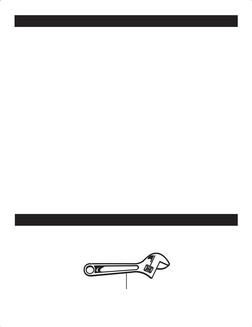
TOOLS NEEDED
The following tools are needed in order to assemble the rubber foot kit.
TWO47/7!ADJUSTABLE$*534!",% 72%WRENCHES.#(%3
8

FEATURES
PRODUCT SPECIFICATIONS
Engine Displacement |
.................................................212 cc |
Air Tank Capacity........................................................ |
9 gal. |
Air Pressure.................................................... |
135 PSI max. |
Air Delivery ........................................... |
11 SCFM @ 40 PSI |
............................................................ |
9.5 SCFM @ 90 PSI |
Lubrication |
.......................................................................Oil |
Gauges....................................................... |
1.5 in. diameter |
Net Weight............................................................... |
150 lbs. |
Fig. 1
GASOLINE
ENGINE
SAFETY
VALVE
AIR INTAKE |
OIL FILL |
FILTER |
PLUG |
TANK 
DRAIN
DRAIN VALVE
VALVE
REAR 
HANDLE
RUBBER |
SAFETY GUARD |
FOOT |
FOR THE V-BELT |
TANK
PRESSURE
GAUGE
PILOT
VALVE
REGULATOR
PRESSURE
GAUGE
AIR
OUTLET
PRESSURE
REGULATOR
KNOB
FRONT
HANDLE
WHEEL
9

FEATURES
KNOW YOUR AIR COMPRESSOR
See Figure 1.
Before attempting to use this product, familiarize yourself with all operating features and safety rules.
DESCRIPTION
Your air compressor is aircooled, splash lubricated, beltdriven, single stage.
DRIVE PULLEYS / FLYWHEELS
Drive pulleys and compressor flywheels must be properly aligned and tensioned to specifications. (Refer to Belt Alignment & Adjustment).
SAFETY VALVES
Safety valves aid in preventing system failures by relieving system pressure when compressed air reaches a pre-determined pressure level. All air receivers must be equipped with an adequately sized safety valve. This type of valve is preset by the manufacturer and must not be modified in any way.
Safety valves are to be placed ahead of any potential blockage point which includes, but not limited to, shutoff valves, heat exchangers, pulsation dampeners, and discharge silencers. Ideally the safety valve should be threaded directly into the pressure point it is sensing, not connected with tubing or pipe, and always pointed away from any chance bystander. All tubing or piping added must be the same size as the safety valve opening or larger.
WARNING!
Excessive compressor RPM’s could cause a pulley or flywheel to shatter, possibly causing bodily harm or death. Do not operate the compressor above the recommended RPM as supplied by the factory.
WARNING!
Safety valves must be provided to protect compressed air systems. Failure to provide properly sized pressure safety valves may cause property damage, severe personal injury or even death.
GUARDS
They must provide protection from moving parts while still allowing full air flow for cooling purposes.
WARNING!
Guards must be fastened in place before starting the compressor. Always stop the unit before removing the guard.
CHECK VALVES
Check valves are designed to allow air to flow freely in one direction only. A properly sized check valve must be provided in the discharge line. Do not rely on a check valve to isolate a compressor from a pressurized tank or compressed air delivery system during maintenance procedures.
PRESSURE REGULATOR KNOB
The pressure regulator knob allows the operator to control the amount of air pressure being supplied to a tool (through the hose). A gauge is provided to indicate the air pressure. To adjust the amount of air pressure supplied:  Pull up on the regulator knob to unlock it.
Turn the knob clockwise to increase pressure - counterclockwise to decrease pressure.
Push the knob down to lock it into position.
REGULATOR PRESSURE GAUGE
The current line pressure is displayed on the regulator pressure gauge. This pressure can be adjusted by rotating the pressure regulator knob.
COMPRESSOR CONTROLS
Gasoline engine driven compressors are equipped with constant run controls and operate continuously until they are manually shut-off. During operation, air is compressed and delivered to the tanks for use. Once the demand for compressed air is satisfied, the in-line unloader (located in the compressor discharge line) is activated, causing the air delivered by the compressor to be discharged to the atmosphere, and allowing the engine to run at a lower speed. In this state, the system is considered to be “unloaded”. As the air stored in the tanks is used and the demand for compressed air returns, the unloader is deactivated, the engine runs at a higher speed, and the compressed air is once again delivered to the tanks for use.
When starting an engine driven unit with air pressure in the tank, flip the toggle on side of the pilot valve to the horizontal position. This will unload the compressor and allow the engine to start easier.
When the engine has run for a few minutes, flip the toggle back to its original position.
AIR FILTER
This compressor is equipped with an air filter to provide a clean air supply, an essential component to the satisfactory operation of your compressor.
WARNING!
Never locate the compressor where toxic, volatile or corrosive vapors, air temperatures exceeding 104°F, water, or extremely dirty air could be ingested. The compressor could be damaged by these atmospheres and result in injury or death.
10
FEATURES
When using the compressor for spray painting, isolate the compressor as far away from the work area as practical, employing extra air hose rather than an extension cord. Warranty will be void if a failure is determined to be caused by dust, dirt or other contaminants.
COMPRESSED AIR DISCHARGE SYSTEM
WARNING!
Discharge piping can exceed 350°F when compressor is operating. Do not use plastic pipe or lead tin soldered joints for a discharge line. Do not modify the discharge line.
PRESSURE VESSELS
Air receiver tanks and other pressure containing vessels must be equipped with a properly sized pressure relief valve, pressure gauge, and a tank drain. The drain valve must be located in the bottom of the air tank(s) to provide for moisture removal.
WARNING!
Pressure vessels must not be modified, welded on, or repaired. Such actions may cause property damage, severe injury, or even death.
TANK PRESSURE GAUGE
The tank pressure gauge indicates the pressure of the air in the tank.
ASSEMBLY
UNPACKING
This product has been shipped completely assembled, except the four rubber feet.
Carefully remove the compressor from the box. Make sure that all items listed in the packing list are included. Inspect the compressor carefully to make sure no breakage or damage occurred during shipping.
Do not discard the packing material until you have carefully inspected and satisfactorily operated the tool. If any parts are damaged or missing, please call
1-800-444-3353 for assistance.
WARNING:
If any parts are missing do not operate the compressor or air tools until the missing parts are replaced. Failure to do so could result in possible serious personal injury.
WARNING:
Do not attempt to modify this tool or create accessories not recommended for use with this tool. Any such alteration or modification is misuse and could result
in a hazardous condition leading to possible serious personal injury.
PACKING LIST
Air Compressor (1)
Operator’s Manual (1)
Replacement Parts List (1)
INSTALLATION
Air compressors should be located in an area that is dry, clean, well lighted, and adequately ventilated.
DANGER!
A gas engine will produce carbon monoxide; always provide adequate ventilation! Do not operate engine in an enclosed area..
Air supplied to the inlet filter must be clean. The compressor belt guard must not be located closer than 12 inches to a wall, or 24 inches to another compressor. Additional safety can be achieved by locating the pulley drive system, with the guard, next to the wall.
The compressor may only be operated in temperatures under 104°F and over 32°F. In cold climates, the compressor should be installed in a heated building.
Proper mounting of the compressor unit is crucial to the safe operation and longevity of the equipment. The installation requires a stable, flat and level surface. Satisfactory results can usually be obtained by mounting the compressor unit on rubber feet supplied with the unit. Refer to Fig. 2.
Uneven feet drawn tightly to a concrete floor or truck bed will cause severe vibrations resulting in cracked welds or fatigue failure. If the unit is mounted to a concrete floor or truck bed or similar foundation, loosen the lock nut several turns & lock it with a back-up nut! The customer
11

ASSEMBLY
is responsible for providing a suitable foundation & rubber foot mounting where necessary.
HIGH ALTITUDE APPLICATIONS
Refer to the engine manufacturer’s recommendations for operation of engines at high altitudes.
ASSEMBLING THE RUBBER FOOT
See Figure 2.
Mount the rubber foot as shown in figure.
Tighten firmly with an open-end wrench (not included) to secure it in position.
DANGER!
Under no circumstances should a compressor be used in an area where toxic, volatile, or corrosive agents are used or stored near the compressor.
CAUTION!
Unusual noise or vibration indicates a problem. Do not operate the compressor until the source has been identified and corrected by a qualified technician.
NUT
WASHER
RUBBER FOOT
SCREW 
Fig. 2
12

OPERATION
DRAINING THE TANK
See Figure 3.
The drain valve is located on the underside of each air tank(s). The compressor can be tilted in the direction of the drain valve in order to allow removal of tank moisture.
To help prevent tank(s) corrosion and keep moisture out of the air used, the tank(s) of the compressor should be drained daily.
WARNING!
Do not open a drain valve on any air tank containing more than 30 PSI of air pressure!
DRAIN
VALVE
DRAIN
VALVE 
(Rotate drain valve right to open) Fig. 3
WARNING!
Never attempt to relieve air pressure in an air tank by removing a pipe plug or any other system component!
WARNING:
Unplug the air compressor and release all air from the tank before servicing. Failure to depressurize tank before attempting to remove valve may cause serious personal injury.
Tank(s) subjected to freezing temperatures may contain ice. Store the compressor in a heated area before attempting to drain moisture from the tank(s).
A correct use of the drain valve:
Verify that the compressor is turned off.
Disconnect the spark plug wire from the spark plug.
Reduce the air pressure in the tank to 30 PSI by pulling the safety valve ring (Fig. 4).
Position yourself so that the moisture and air to be expelled can not cause you harm.
Holding the handle, tilt the compressor toward the drain valve so that it’s set in a lower position.
Open the drain valve completely, allowing the moisture and air mixture to drain from the tank.
Keep the compressor tilted until all moisture has been removed.
Once the moisture has been completely drained, close the drain valve.
Drain moisture from tank into a suitable container.
NOTE: Condensate is a polluting material and should be disposed of in compliance with local regulations.
If drain valve is clogged, release all air pressure by pulling the safety valve. Remove and clean valve, then reinstall.
WARNING:
Do not attempt to tamper with safety valve. Anything loosened from this device could fly up and hit you. Failure to heed this warning could result in death or serious personal injury.
SAFETY
VALVE
Fig. 4
Turn off drain valve until completely closed.
CHECKING THE SAFETY VALVE
See Figure 4.
WARNING:
If air leaks after the ring has been released, or if the valve is stuck and cannot be actuated by the ring, Do Not use the air compressor until the safety valve has been replaced. Use of the air compressor in this condition could result in serious personal injury.
The safety valve will automatically release air if the air receiver pressure exceeds the preset maximum. The valve should be checked before each day of use by pulling the ring by hand.
Turn the air compressor on and allow the tank to fill. The compressor will shut off when the pressure reaches the preset maximum.
Turn the air compressor off.
Pull the ring on the safety valve to release air for twenty seconds.
Release the ring. Air must immediately stop escaping when the ring is released. Any continued loss of air after releasing the safety valve ring indicates a problem with the safety valve. Discontinue use and seek service before continued use of the air compressor.
13

OPERATION
WARNING:
Do not allow familiarity with tools to make you careless. Remember that a careless fraction of a second is sufficient to inflict serious injury.
WARNING:
Always wear safety goggles or safety glasses with side shields when operating power tools. Failure to do so could result in objects being thrown into your eyes resulting in possible serious injury.
CAUTION:
Do not use in an environment that is dusty or otherwise contaminated. Using the air compressor in this type of environment may cause damage to the unit.
APPLICATIONS
Air compressors are utilized in a variety of air system applications. Match hoses, connectors, air tools, and accessories to the capabilities of the air compressor.
You may use this tool for purposes listed below:
Operating some air-powered tools.
Inflating tires, air beds, sports equipment, etc.
PRE-STARTING CHECKLIST
WARNING!
Failure to perform the PRE-STARTING CHECKLIST may result in mechanical failure, property damage, serious injury or even death.
The following steps should be performed prior to operating the unit. If any condition of the checklist is not satisfied, make the necessary adjustments or corrections before starting the compressor.
WARNING!
Neverassumeacompressorissafetoworkonjustbecause it is not operating. It could restart at any time. Follow all safety precautions outlined in MAINTENANCE.
The compressor is shipped with lubricant in the crankcase. Check lubricant level per specifications (using the instruction found in Lubrication). Make sure all safety valves are correctly installed. (using the instruction found in Features).
Be sure all guards are in place and securely mounted (using the instruction found in Features).
Drain moisture from the air tank(s). Never attempt to drain the tank(s) without first relieving the system
pressure (using the instruction found in Draining the Tank).
STARTING & STOPPING THE COMPRESSOR
Connect the air line to the quick coupler.
Rotate regulator knob fully counterclockwise in order to close the air flow.
Ensure both drain valves are closed.
Fill the engine with oil through oil fill hole.
Fill the compressor pump with oil. Do not overfill.
Fill the fuel tank with fuel.
Open the petcock on the unloader valve for cold starts (turn clockwise or in).
Flip the toggle on the pilot valve to the “MANUAL UNLOAD” position (see Pilot Valve Adjustments).
Start the gas engine (refer to gas engine owner’s manual for more detailed start-up procedures):
–Adjust choke and open fuel valve.
–Pull the cord.
–Move choke to run.
Watch and listen for excessive vibration and unusual noises. If either exist, stop the compressor and refer to
Troubleshooting.
Allow the compressor to run for a few minutes. Close the petcock (turn counterclockwise or out).
Flip the toggle on the pilot valve to the “RUN” position. The compressor should pump up the tank to 135
PSI, then unload. If pressure exceeds 135 PSI, see
Troubleshooting.
New compressors should be run with approximately 80 PSI of air pressure in the tank for 1 hour to break-in (use regulator to control tank pressure). This will allow the compressor time to warm up and seat the rings.
To stop the compressor, shut the engine off.
USING THE AIR COMPRESSOR
See Figure 5.
WARNING:
Always ensure the regulator pressure gauge read zero before changing air tools or disconnecting the hose from the air outlet. Failure to do so could result in possible serious personal injury.
Rotate pressure regulator knob to desired line pressure. Turning the knob clockwise increases air pressure at the outlet; turning counterclockwise reduces air pressure at the outlet.
14

OPERATION
WARNING:
Your tool may require more air consumption than this air compressor is capable of providing. Check the tool manual to avoid damage to the tool or risk of personal injury.
Following all safety precautions in this manual and the manufacturer’s instructions in the air tool manual, you may now proceed to use your air-powered tool.
If using an inflation accessory, control the amount of air flow with the pressure regulator knob. Turning the knob fully counterclockwise will completely stop the flow of air.
NOTE: Always use the minimum amount of pressure necessary for your application. Using a higher pressure than needed will drain air from the tank more rapidly and cause the unit to cycle on more frequently.
When finished, always drain the tank and stop the compressor. Never leave the unit in running unattended.
END OF OPERATION/STORAGE
Shut off the engine.
Disconnect the spark plug wire from the spark plug and wrap around handle area to prevent damage when not in use.
Wearing safety glasses drain tank of air by pulling the ring on the safety valve. Use other hand to deflect fast moving air from being directed toward your face.
Drain tank of condensation by opening both drain valves on bottom of tank. Tank pressure should be below 10 psi when draining tank.
Air hose should be disconnected from compressor and hung open ends down to allow any moisture to drain.
Compressor and hose should be stored in a cool, dry place.
TANK |
REGULATOR |
AIR |
PRESSURE |
PRESSURE |
PRESSURE |
OUTLET |
REGULATOR |
GAUGE |
GAUGE |
|
KNOB |
Fig. 5
15
 Loading...