


60794
Owner’s Manual & Safety Instructions
Save This Manual Keep this manual for the safety warnings and precautions, assembly,
operating, inspection, maintenance and cleaning procedures. Write the product’s serial number in the
back of the manual near the assembly diagram (or month and year of purchase if product has no number).
Keep this manual and the receipt in a safe and dry place for future reference.
Visit our website at: http://www.harborfreight.com
REV 14h
When unpacking, make sure that the product is intact
and undamaged. If any parts are missing or broken,
please call 1-888-866-5797 as soon as possible.
Copyright© 2012 by Harbor Freight Tools®. All rights reserved.
No portion of this manual or any artwork contained herein may be reproduced in
any shape or form without the express written consent of Harbor Freight Tools.
Diagrams within this manual may not be drawn proportionally. Due to continuing
improvements, actual product may differ slightly from the product described herein.
Tools required for assembly and service may not be included.
Email our technical support at: productsupport@harborfreight.com
Read this material before using this product.
Failure to do so can result in serious injury.
SAVE THIS MANUAL.

Table of Contents
1. Safety Precautions And Warnings ....................... 3
2. General Information ..............................................4
3. Using the Scan Tool ...............................................
4. Review Data ..........................................................26
5. Diagnostics ...........................................................28
6. ABS Testing ...........................................................69
7. Print Data...............................................................73
8. Appendix ...............................................................75
9. Limited 90 Day Warranty ...................................... 84
Page 2 For technical questions, please call 1-888-866-5797. Item 60794

1. Safety Precautions And Warnings
To prevent personal injury or damage to vehicles
and/ or the Scan Tool, read this instruction manual
first and observe the following safety precautions,
at a minimum, whenever working on a vehicle:
1. Always perform automotive testing in a safe environment.
2. Wear safety eye protection that meets ANSI standards.
3. Keep clothing, hair, hands, tools, test equipment,
etc. away from all moving or hot engine parts.
4. Operate the vehicle in a well-ventilated work area:
Exhaust gases are poisonous.
5. Put blocks in front of the drive wheels and never
leave the vehicle unattended while running tests.
6. Use extreme caution when working around the
ignition coil, distributor cap, ignition wires and
spark plugs. These components create hazardous
voltages when the engine is running.
7. Put the transmission in PARK (for automatic
transmission) or NEUTRAL (for manual transmission)
and make sure the parking brake is engaged.
8. Keep a fire extinguisher suitable for gasoline/
chemical/electrical fires nearby.
9. Don't connect or disconnect any test equipment
while the ignition is on or the engine is running.
10. Keep the Scan Tool dry, clean, free from oil, water or
grease. Use a mild detergent on a clean cloth to clean
the outside of the Scan Tool, when necessary.
Page 3For technical questions, please call 1-888-866-5797.Item 60794

2. General Information
2.1 On-Board Diagnostics (OBD) II
The first generation of On-Board Diagnostics (called OBD I)
was developed by the California Air Resources Board
(ARB) and implemented in 1988 to monitor some of the
emission control components on vehicles. As technology
evolved and the desire to improve the On-Board Diagnostic
system increased, a new generation of On-Board Diagnostic
system was developed. This second generation of OnBoard Diagnostic regulations is called OBD II.
The OBD II system is designed to monitor emission control systems
and key engine components by performing either continuous or
periodic tests of specific components and vehicle conditions. When
a problem is detected, the OBD II system turns on a warning lamp
(MIL) on the vehicle instrument panel to alert the driver typically
by the phrase of “Check Engine” or “Service Engine Soon”.
The system will also store important information about the
detected malfunction so that a technician can accurately
find and fix the problem. Here are three examples:
1. Whether the Malfunction Indicator Light
(MIL) is commanded 'on' or 'off'
2. Which, if any, DTCs are stored
3. Readiness Monitor status
Page 4 For technical questions, please call 1-888-866-5797. Item 60794
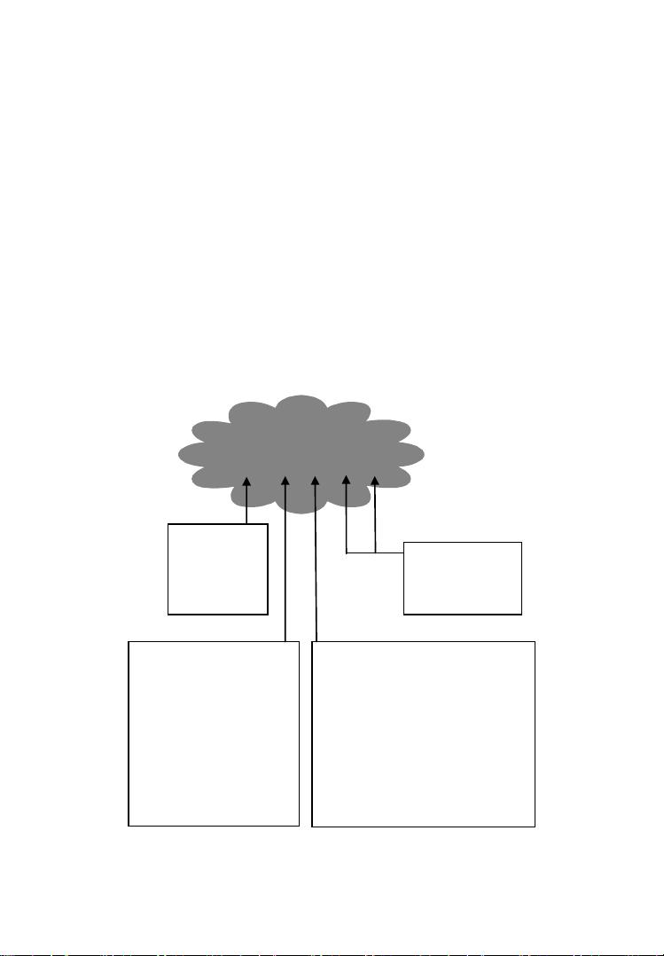
2.2 Diagnostic Trouble Codes (DTCs)
Identifying specific
malfunctioning
section of the
systems
Systems
B=Body
C=Chassis
P=Powertrain
U=Network
Code Type
Generic (SAE):
P0, P2, P34-P39
B0, B3
C0, C3
U0, U3.
Manufacturer Specific:
P1, P30-p33
B1, B2
C1, C2
U1, U2
Sub-systems
1= Fuel and Air Metering
2= Fuel and Air Metering
3= Ignition System or Engine Misfire
4= Auxiliary Emission Controls
5= Vehicle Speed Control and Idle
Controls
6= Computer Output Circuits
7= Transmission Controls
8= Transmission Controls
DTC Example
P 0 2 0 2
OBD II DTCs are codes that are stored by the vehicles' OnBoard Diagnostic system in response to a problem found
in the vehicle. These codes identify a particular problem
area and are intended to provide you with a guide as to
where a fault might be occurring within a vehicle.
OBD II DTCs consists of a five-digit alphanumeric code.
The first character, a letter, identifies which control system
sets the code. The other four characters, all numbers, provide
additional information on where the DTC originated and
the operating conditions that caused it to set. Here below
is an example to illustrate the structure of the digits:
Page 5For technical questions, please call 1-888-866-5797.Item 60794

2.3 Location of the Data Link Connector (DLC)
The DLC is the standardized 16-cavity connector where diagnostic
Scan Tools interface with the vehicle's on-board computer. The
DLC is usually located 12 inches from the center of the instrument
panel (dash), under or around the driver's side for most vehicles.
If the DLC is not located under dashboard, a label should be
there indicating its location. For some Asian and European
vehicles, the DLC is located behind the ashtray and the ashtray
must be removed to access the connector. If the DLC cannot be
found, refer to the vehicle’s Owner's Manual for the location.
2.4 OBD II Readiness Monitors
An important part of a vehicle's OBD II system are the Readiness
Monitors, which are indicators used to find out if all of the emissions
components have been evaluated by the OBD II system. They
are running periodic tests on specific systems and components
to ensure that they are performing within allowable limits.
Currently, there are eleven OBD II Readiness Monitors (or
I/M Monitors) defined by the U.S. Environmental Protection
Agency (EPA). Not all monitors are supported by all vehicles
and the exact number of monitors in any vehicle depends on
the motor vehicle manufacturer's emissions control strategy.
Page 6 For technical questions, please call 1-888-866-5797. Item 60794

Continuous Monitors
Some of the vehicle components or systems are continuously
tested by the vehicle's OBD II system, while others are tested
only under specific vehicle operating conditions. The continuously
monitored components listed below are always ready:
1. Misfire
2. Fuel System
3. Comprehensive Components (CCM)
Once the vehicle is running, the OBD II system is continuously
checking the above components, monitoring key engine sensors,
watching for engine misfire, and monitoring fuel demands.
Non-Continuous Monitors
Unlike the continuous monitors, many emissions and engine
system components require the vehicle to be operated
under specific conditions before the monitor is ready.
2.5 OBD II Monitor Readiness Status
OBD II systems must indicate whether or not the vehicle's PCM
monitor system has completed testing on each component.
Components that have been tested will be reported as “Ready”, or
“Complete”, meaning they have been tested by the OBD II system.
The purpose of recording readiness status is to allow
technicians to determine if the vehicle's OBD II system
has tested all the components and/or systems.
Page 7For technical questions, please call 1-888-866-5797.Item 60794

The Power-Train Control Module (PCM) sets a monitor to
“Ready” or “Complete” after an appropriate drive cycle has
been performed. The drive cycle that enables a monitor and
sets readiness codes to “Ready” varies for each individual
monitor. Once a monitor is set as “Ready” or “Complete”, it
will remain in this state. A number of factors, including erasing
of DTCs with a Scan Tool or a disconnected battery, can
result in Readiness Monitors being set to “Not Ready”.
Since the three continuous monitors are constantly evaluating, they
will be reported as “Ready” all of the time. If testing of a particular
supported non-continuous monitor has not been completed, the
monitor status will be reported as “Not Complete” or “Not Ready.”
In order for the OBD II monitor system to become ready,
the vehicle should be driven under a variety of normal
operating conditions. These operating conditions may
include a mix of highway driving and stop and go, city type
driving, and at least one overnight-off period. For specific
information on getting your vehicle's OBD II monitor system
ready, please consult your vehicle's Owner's Manual.
2.6 OBD II Definitions
Power-Train Control Module (PCM) -- The vehicle's on-
board computer that controls engine and drive train.
Malfunction Indicator Light (MIL) -- Malfunction Indicator Light
(Service Engine Soon, Check Engine) is a term used for the light
on the instrument panel. It is to alert the driver and/or the repair
technician that there is a problem with one or more of vehicle's
systems and may cause emissions to exceed federal standards.
If the MIL illuminates with a steady light, it indicates that
a problem has been detected and the vehicle should be
serviced as soon as possible. Under certain conditions, the
MIL will blink or flash. This indicates a severe problem and
flashing is intended to discourage vehicle operation.
Page 8 For technical questions, please call 1-888-866-5797. Item 60794
The vehicle's On-Board Diagnostic system cannot turn
the MIL off until necessary repairs are completed or
the condition no longer exists.
DTC -- Diagnostic Trouble Code that identifies which section
of the emission control system has malfunctioned.
OBD II Drive Cycle -- A specific mode of vehicle operation that
provides conditions required to set all the Readiness Monitors
applicable to the vehicle to the “Ready” condition. The purpose
of completing an OBD II drive cycle is to force the vehicle to run
its on-board diagnostics. Some form of a drive cycle needs to be
performed after DTCs have been erased from the PCM's memory
or after the battery has been disconnected. Running through a
vehicle's complete drive cycle will “set” the Readiness Monitors
so that future faults can be detected. Drive cycles vary depending
on the vehicle and the monitor that needs to be reset. For vehicle
specific drive cycle, consult the vehicle's Owner's Manual.
Freeze Frame Data -- When an emissions related fault occurs, the
OBD II system not only sets a code but also records a snapshot of
the vehicle operating parameters to help in identifying the problem.
This set of values is referred to as Freeze Frame Data and may
include important engine parameters such as engine RPM, vehicle
speed, air flow, engine load, fuel pressure, fuel trim value, engine
coolant temperature, ignition timing advance, or closed loop status.
Parameter ID (PID) --
Page 9For technical questions, please call 1-888-866-5797.Item 60794
3. Using the Scan Tool
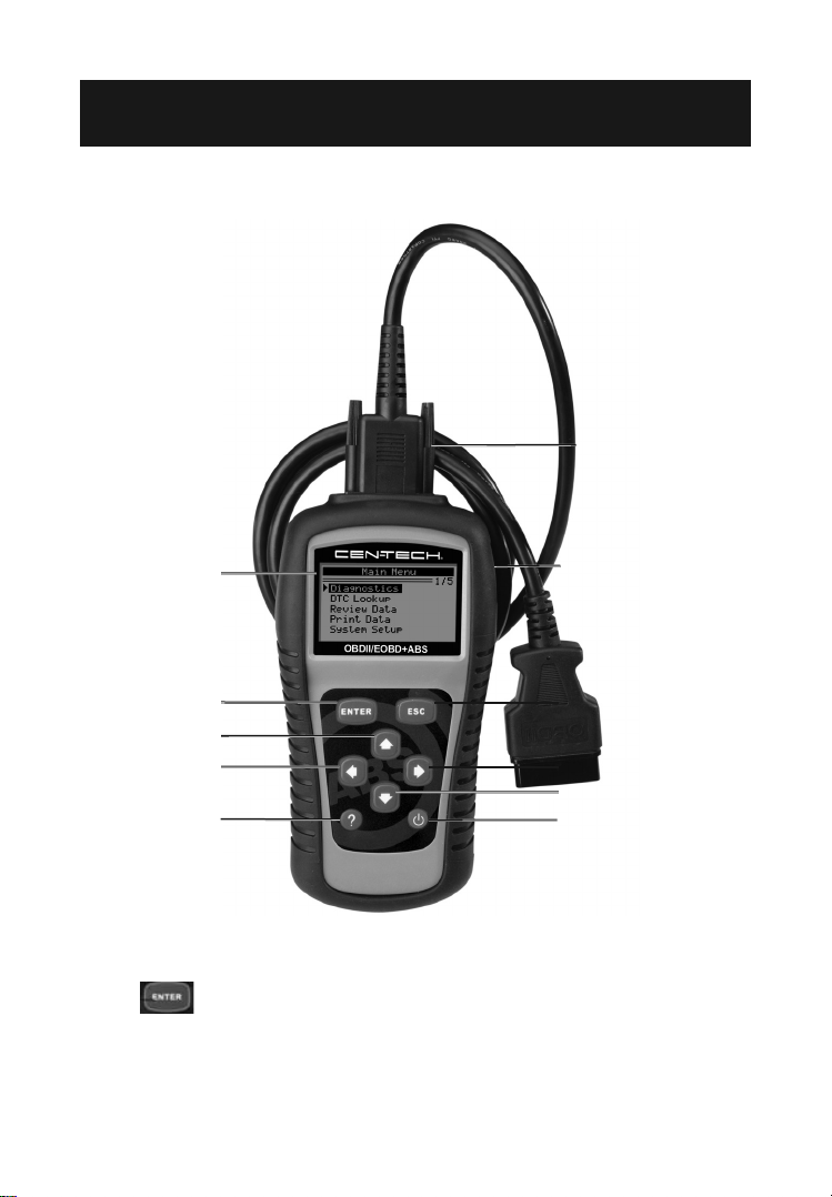
3.1 Tool Description
10
1
2
6
4
8
1. LCD Display – Displays menus and test results.
2. ENTER BUTTON – Confirms a selection
(or action) from a menu. Starts recording live
data under Manual Trigger mode.
Page 10 For technical questions, please call 1-888-866-5797. Item 60794
11
3
5
7
9

3. ESC BUTTON – Cancels a selection (or action)
from a menu or returns to the previous menu.
4. LEFT SCROLL BUTTON – When looking up DTC
definitions, moves to previous screens if DTC definition
covers more than one screen; deselects all marked
PID data when viewing or recording customized live
data list; moves to previous frames of data when
playing back live data. Updates DTC library.
5. RIGHT SCROLL BUTTON – When looking up DTC
definitions, moves to next screens if DTC definition covers
more than one screen; selects/deselects PID data when
viewing or recording customized live data list; moves
to next frames of data when playing back live data.
6. UP SCROLL BUTTON – Moves up through menu
and submenu items in menu mode. When more than one
screen of data is retrieved, moves up through the current
screen to the previous screens for additional data.
7. DOWN SCROLL BUTTON – Moves down through
menu and submenu items in menu mode. When
more than one screen of data is retrieved, moves
down through the current screen to next screens for
additional data. It is also used for language setup.
8. HELP BUTTON – Provides Help and
Code Breaker information.
9. POWER SWITCH – Turns the Scan Tool
on/ off when powered by 9V battery; resets the
Scan Tool when powered by vehicle battery.
10. OBD II CONNECTOR – Connects the
Scan Tool to the vehicle’s DLC.
11. USB CONNECTOR – Connects the Scan Tool
to a computer for printing and upgrading.
Page 11For technical questions, please call 1-888-866-5797.Item 60794

3.2 Specifications
Display: Backlit, 128 x 64 pixel display with contrast adjustment
Operating Temperature: 0 to 60°C (32 to 140 F°)
Storage Temperature: -20 to 70°C (-4 to 158 F°)
External Power: 8.0 to 18.0 V power provided via vehicle battery
Internal Power: 9V battery
3.3 Accessories Included
1. OBD II Cable – Provides power to tool and
communicates between tool and vehicle.
2. USB Cable – Used to upgrade the Scan
Tool, and to print retrieved data.
3. 9V Battery
4. User's Manual – Instructions on tool operations.
5. CD – Includes user's manual, update software, etc.
3.4 Navigation Characters
1. ► – Indicates current selection.
2. – Indicates additional information is
available on next screen(s).
3. – Indicates additional information is
available on previous screen(s).
4. $ – Identifies the control module number
from which data is retrieved.
5. ? – Indicates Help or Code Breaker information is available.
6. G – Indicates graphic viewing is available.
7. – Indicates battery volume.
Page 12 For technical questions, please call 1-888-866-5797. Item 60794

3.5 Keyboard
No solvents such as alcohol are allowed to clean the Keyboard or
Display. Use a mild nonabrasive detergent and a soft cotton cloth.
Do not soak the Keyboard as the Keyboard is not waterproof.
3.6 Power
Internal Power
The Scan Tool has a 9V battery that provides
power for off-car reviewing and analysis. Press
the power key to turn on the Scan Tool.
Note: If the Scan Tool is stored for a long period of time, remove
the battery to prevent damage to the Scan Tool.
External Power
The Scan Tool is powered via the vehicle's DLC. Just
follow the steps below to turn on the Scan Tool:
1. Connect the OBD II Cable to Scan Tool.
2. Find the DLC on vehicle.
3. Plug OBD II cable to the vehicle's DLC.
Page 13For technical questions, please call 1-888-866-5797.Item 60794
3.7 DTC Lookup
The DTC Lookup function is used to search for definitions of DTCs
stored in the DTC library and for Code Breaker information.
1. From Main Menu, use the Up/Down scroll button to
select DTC Lookup then press the ENTER button.
Main Menu
Diagnostics
DTC Lookup
Review Data ?
Print Data
System Setup
Tool Information
2/6
Figure 3.1
• The numbers x/y in the upper right corner = where
x indicates the sequence of highlighted item and y
indicates total number of items under the menu.
• Press the ? button to view Help information of selected item.
2. From DTC Lookup menu, use the Left/Right
button to move to the desired character, use the Up/
Down button to change selected digit/character,
then press the ENTER button to confirm.
DTC Lookup
P 0 0 0 1
[ ] – Left [ ] - Right
[ ][ ]- Change Digit
[ENTER]- Confirm
[ESC]- Exit
Figure 3.2
Page 14 For technical questions, please call 1-888-866-5797. Item 60794

3. View the DTC definition on screen. When the DTC definition
covers more than one screen, use the Left/Right button
to view additional information on previous/next screens.
• For manufacturer specific codes, you need
to select a vehicle make on an additional
screen to look for DTC definitions.
• If definition could not be found (SAE or Manufacturer
Specific), the Scan Tool displays “DTC definition not
found! Please refer to vehicle's User's Manual!”
• For Code Breaker information, press the ? button.
4. To view previous or next DTC in the built- in
DTC library, use the Up/Down button.
5. To enter another DTC, press the ESC
button to return to previous screen.
6. To exit to Main Menu, press the ESC button.
3.8 System Setup
The Scan Tool allows you to make the following
adjustments and settings:
1. Language: Selects the desired language.
2. Contrast: Adjusts the contrast of the LCD display
3. Unit of Measure: Sets the unit of measure to
English or Metric.
4. Auto Power-Off: Sets automatic power-off limits.
5. Beep Set: Turns on/off beep.
6. Tool Self-test: Checks if the LCD display
and Keyboard are working normally.
Page 15For technical questions, please call 1-888-866-5797.Item 60794
7. Tool Information: Allows viewing of some
important information such as serial number and
software version number of the Scan Tool.
8. Update Mode: Used for updating the Scan Tool.
• Settings of the unit will remain until change
to the existing settings are made.
To Enter the System Setup Menu
From the Main Menu, use the Up/Down scroll button to
select System Setup, then press the ENTER button.
............ ..Main Menu…… ……………
Diagnostics
DTC Lookup
Review Data ?
Print Data
System Setup
Tool Information
5/6
Figure 3.3
Language
•English is the default language.
1. From System Setup menu, use the Up/Down scroll button
to select Language, then press the ENTER button.
System Setup
1/6
Language
Contrast
Unit of Measure ?
Auto Power-off
Beep Set
Tool Self-test
Figure 3.4
Page 16 For technical questions, please call 1-888-866-5797. Item 60794
2. Use the Up/Down scroll button to select the desired
Tool Self-test
language, then press the ENTER button to save
your selection and return to previous screen.
Language
English
Français
Español
1/3
Figure 3.5
Contrast
1. From System Setup menu, use the Up/Down scroll button
to select Contrast, then press the ENTER button.
System Setup
Language
Contrast
2/6
Unit of Measure ?
Auto Power-Off
Beep Set
Figure 3.6
Page 17For technical questions, please call 1-888-866-5797.Item 60794
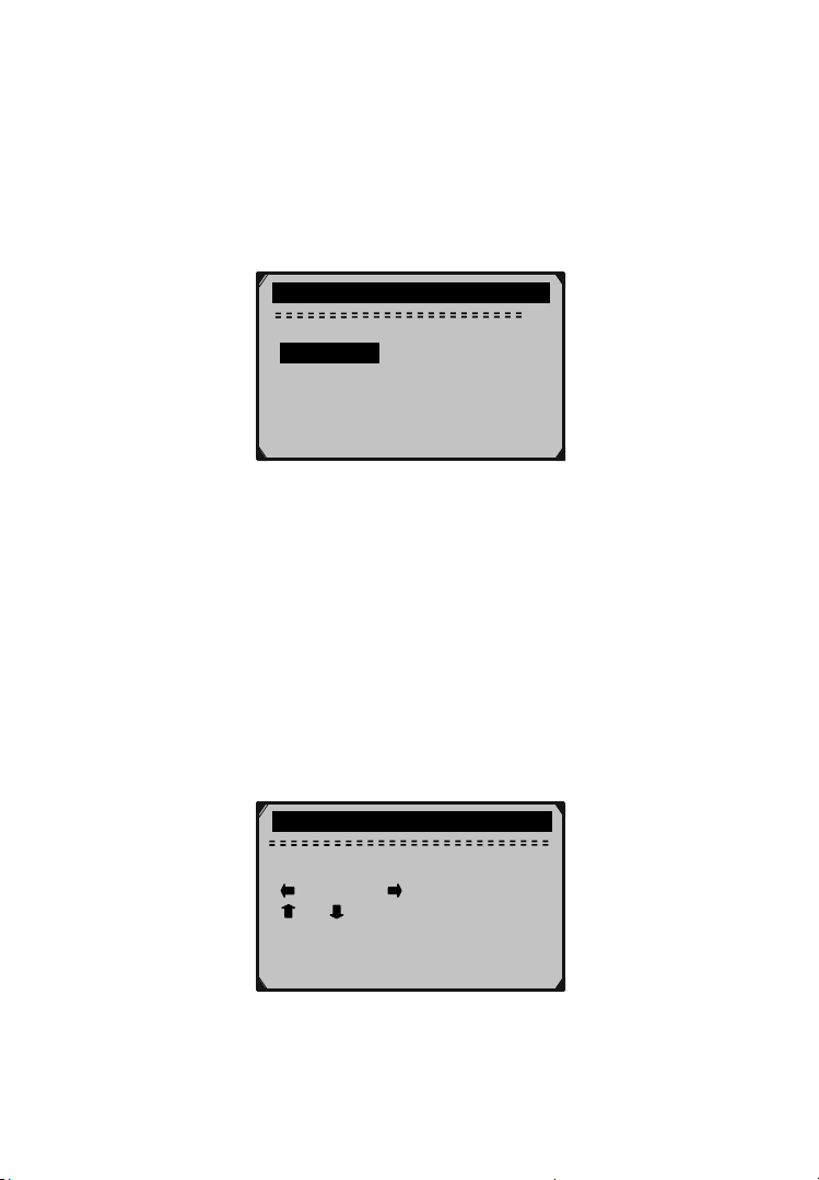
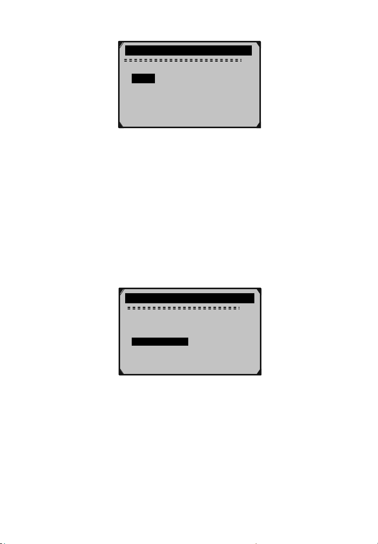
2. From Contrast menu, use the Up/Down scroll button to
increase or decrease contrast, then press the ENTER button
to save your settings and return to the previous menu.
Contrast
(30%)
Use
or
to change
Figure 3.7
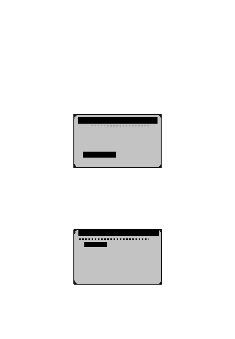
Unit of Measure
• Metric is the default measurement unit.
1. From System Setup menu, use the Up/Down scroll button
to select Unit of Measure, then press the ENTER button.
System Setup
Language
Contrast
Unit of Measure ?
2. From Unit of Measure menu, use the Up/ Down scroll
button to select the desired unit of measurement,
then press the ENTER button to save your
settings and return to the previous menu..
3/6
Auto Power-off
Beep Set
Tool Self-test
Figure 3.8
Page 18 For technical questions, please call 1-888-866-5797. Item 60794
…………….Unit of Measure…… … ….
English
Metric ?
2/2
Figure 3.9
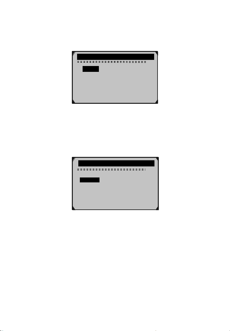
Auto Power-Off
• The minimum Auto Power-Off time is 1
minute, and the maximum is 20 minutes.
• The Auto Power-Off function is available only
when the Scan Tool is powered by 9V battery.
1. From System Setup menu, use the Up/Down scroll button
to select Auto Power-Off then press the ENTER button.
System Setup
Language
Contrast
Unit of Measure ?
Auto Power-off
4/6
Beep Set
Tool Self-test
Figure 3.10
Page 19For technical questions, please call 1-888-866-5797.Item 60794
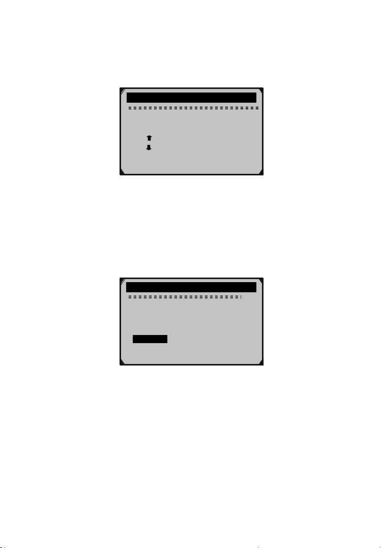
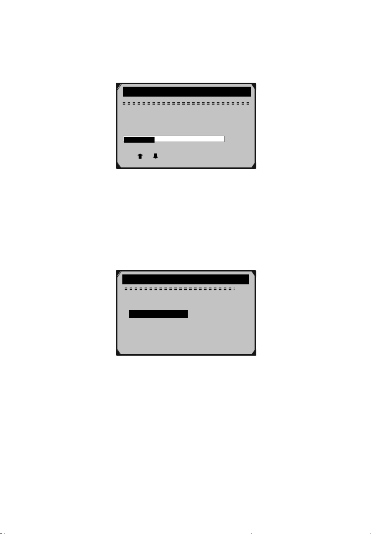
2. From Auto Power-Off menu, use the Up/Down scroll button
to increase or decrease time, then press the ENTER button
to save your settings and return to the previous menu.
Auto Power-off
01 Minute
[
] – Increase time
] – Decrease time
[
[ENTER] - Confirm
Figure 3.11
Beep Set
•The default setting is Beep On.
1. From System Setup menu, use the Up/Down scroll
button to select Beep Set then press the ENTER button.
System Setup
Language
Contrast
Unit of Measure ?
Auto Power-off
Beep Set
5/6
Tool Self-test
Figure 3.12
2. From Beep Set menu, use the Up/Down scroll button to
select Beep ON or Beep OFF, then press the ENTER button
to save your settings and return to the previous menu.
Page 20 For technical questions, please call 1-888-866-5797. Item 60794
Beep Set
Beep ON
Beep OFF ?
2/2
Figure 3.13
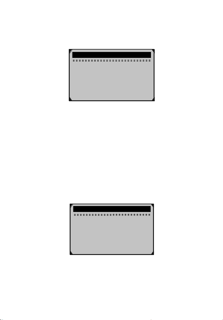
Tool Self-test
A. Display test
The Display Test function checks if the
LCD display is working normally.
1. From System Setup menu, use the Up/Down scroll button
to select Tool Self-test, then press the ENTER button.
System Setup
Language
Contrast
Unit of Measure ?
Auto Power-off
Beep Set
Tool Self-test
6/6
Figure 3.14
Page 21For technical questions, please call 1-888-866-5797.Item 60794
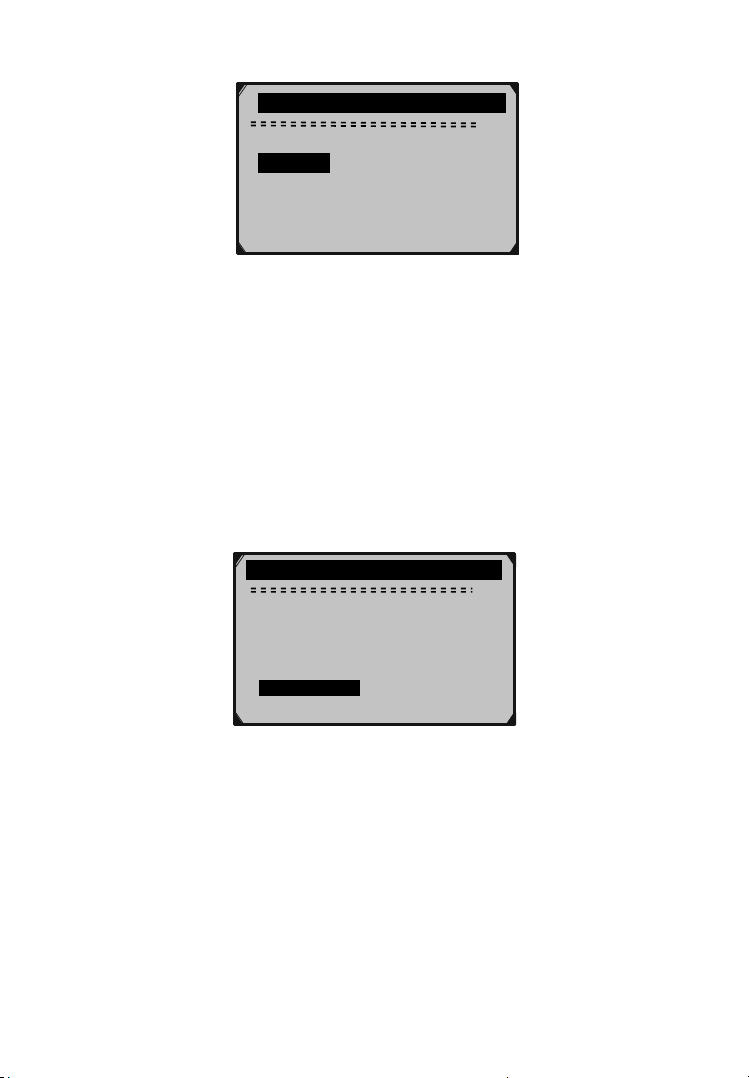
2. Select Display Test from Tool Self-test
menu then press the ENTER button.
Tool Self-test
Display Test
1/2
Keyboard Test ?
Figure 3.15
3. Press the ENTER button again to start test. Look
for missing spots in the solid black characters.
4. When completed, press the ESC button
to return to the previous screen.
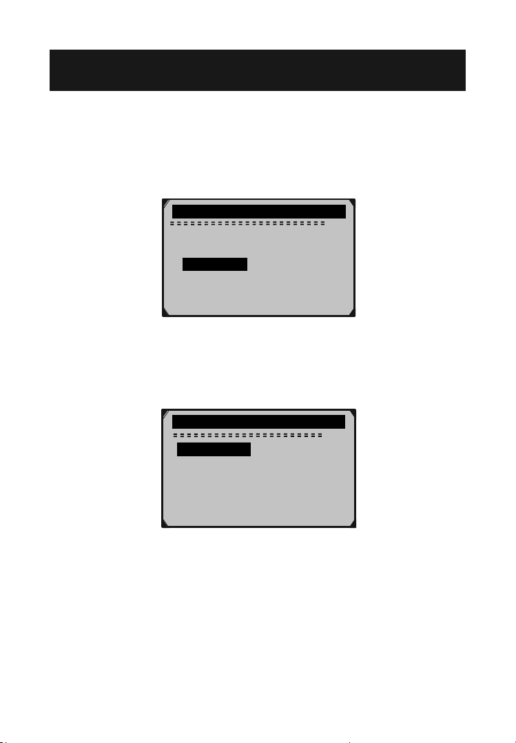
B. Keyboard Test
The Keyboard Test function verifies that
the keys are functioning properly.
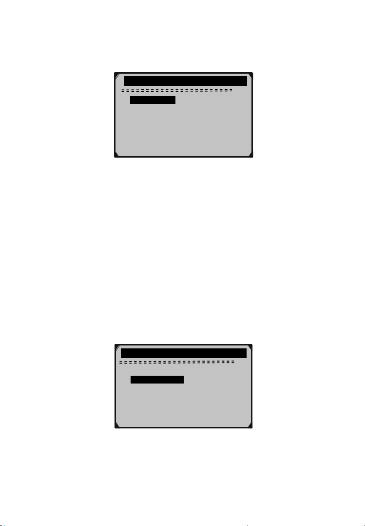
1. Use the Up/Down scroll button to select Keyboard Test from
the Tool Self-test menu, then press the ENTER button.
Tool Self-test
Display Test
2/2
Keyboard Test ?
Figure 3.16
Page 22 For technical questions, please call 1-888-866-5797. Item 60794
2. Press any key to start test. When you press a key, the key
name should be observed on the display. If the key name
does not show up, then the key is not functioning properly.
Keyboard Test
Press any key to
start test
key:
Double [ESC] to return
Figure 3.17
When you press the Power button, the key name will not show on
the screen. Instead, the Scan Tool should reset when powered by
vehicle battery, or turn off when powered by 9V battery. If the Scan
Tool does not reset or turn off, the key is not working properly.
3. Double press ESC to return to previous menu.
Tool Information
1. From System Setup menu, use the Up/Down scroll button
to select Tool Information, then press the ENTER button.
Tool Information
Serial No. : 00000006
Burn Date: 05/03/11
S/W Ver : V3.00
H/W Ver : V1.02
LIB Ver : V1.01
Figure 3.18
2. When completed, press the ESC button
to return to the previous screen.
Page 23For technical questions, please call 1-888-866-5797.Item 60794

Update Mode
This function allows you to update the Scan Tool
software and DTC library through a computer.
• Visit www.HarborFreight.com to
update the Scan Tool software.
3.9 9V Battery Replacement
When the icon appears on the screen, replace the battery.
1. Locate the battery cover on the back of the Scan Tool.
2. Remove the battery cover screw and
slide the battery cover off.
3. Remove discharged battery and install a new 9V battery.
4. Reinstall battery cover by sliding battery
cover on and installing screw.
3.10 Vehicle Coverage
The 60794 Scan Tool is designed to work with all OBD II compliant
vehicles, including those equipped with Control Area Network
(CAN). It is required by EPA that all 1996 and newer vehicles (cars
and light trucks) sold in the United States must be OBD II compliant
and this includes all Domestic, Asian and European vehicles.
A small number of 1994 and 1995 model year gasoline vehicles
are OBD II compliant. To verify if a 1994 or 1995 vehicle
is OBD II compliant, check the Vehicle Emissions Control
Information (VECI) Label which is located under the hood
or by the radiator of most vehicles. If the vehicle is OBD II
compliant, the label will designate “OBD II Certified”.
Additionally, Government regulations mandate that all OBD II
compliant vehicles must have a “common” sixteen-pin DLC.
Page 24 For technical questions, please call 1-888-866-5797. Item 60794

3.11 Product Troubleshooting
Vehicle Linking Error
A communication error occurs if the Scan Tool fails to
communicate with the vehicle's Engine Control Unit (ECU).
You need to do the following to identify the error:
1. Verify that the ignition is ON.
2. Verify that the Scan Tool's OBD II connector is
securely connected to the vehicle's DLC.
3. Turn the ignition off and wait for about 10 seconds.
Turn the ignition back to on and continue the testing.
Operating Error
If the Scan Tool freezes, an exception occurs, or the vehicle's ECU
is too slow to respond to requests, you need to reset the Scan Tool:
1. Press and hold the POWER button for at least 2 seconds.
2. Turn the ignition off and wait for about 10 seconds.
Turn the ignition back to on and continue the testing.
Scan Tool doesn’t power up
If the Scan Tool won't power up or operates incorrectly
in any other way, you need to do the following:
1. Verify that the Scan Tool's OBD II connector is
securely connected to the vehicle's DLC.
2. Verify that the DLC pins are not bent or broken.
Clean the DLC pins if necessary.
3. Verify that the vehicle battery measures at least 8 volts.
Page 25For technical questions, please call 1-888-866-5797.Item 60794
4. Review Data
The Review Data function allows viewing of data
from the last test recorded by the Scan Tool.
1. Use the Up/Down scroll button to select Review Data
from Main Menu, then press the ENTER button.
Main Menu
Diagnostics
DTC Lookup
Review Data ?
Print Data
System Setup
Tool Information
2. Use the Up/Down scroll button to select the desired item
from Review Data menu, then press the ENTER button.
Review Data
I/M Readiness
Vehicle Info.
Modules Present ?
Trouble codes (ABS)
3/6
Figure 4.1
1/4
Figure 4.2
Page 26 For technical questions, please call 1-888-866-5797. Item 60794
 Loading...