

Page 1

GRILLO G85 - D
GRILLO G107D
EDIZIONE 2006
02161
Page 2

2
8
10
11
11
13
14
62
70
2
18
20
21
21
23
24
62
70
2
28
30
31
31
33
34
62
70
2
38
40
41
41
43
44
62
70
2
48
50
51
51
53
54
62
70
Page 3

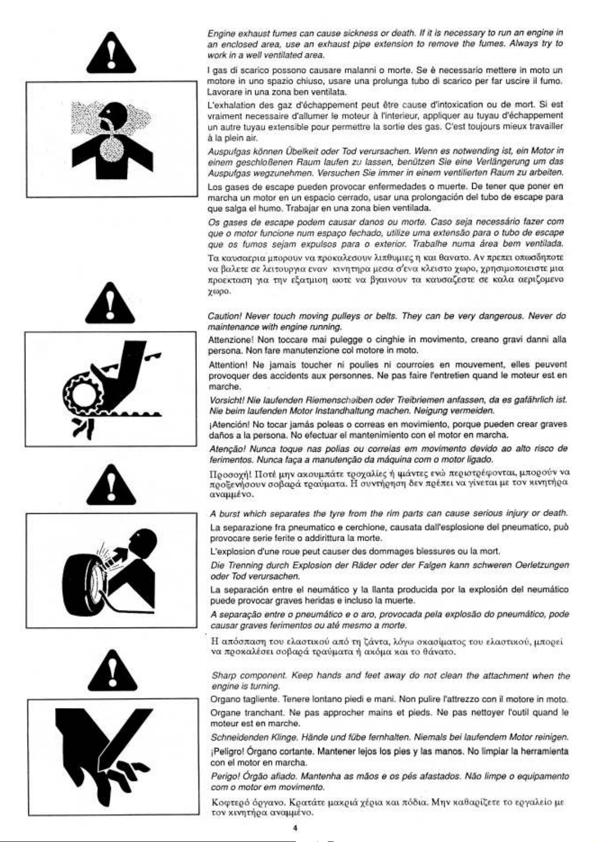
Page 4

Page 5
Page 6

Page 7
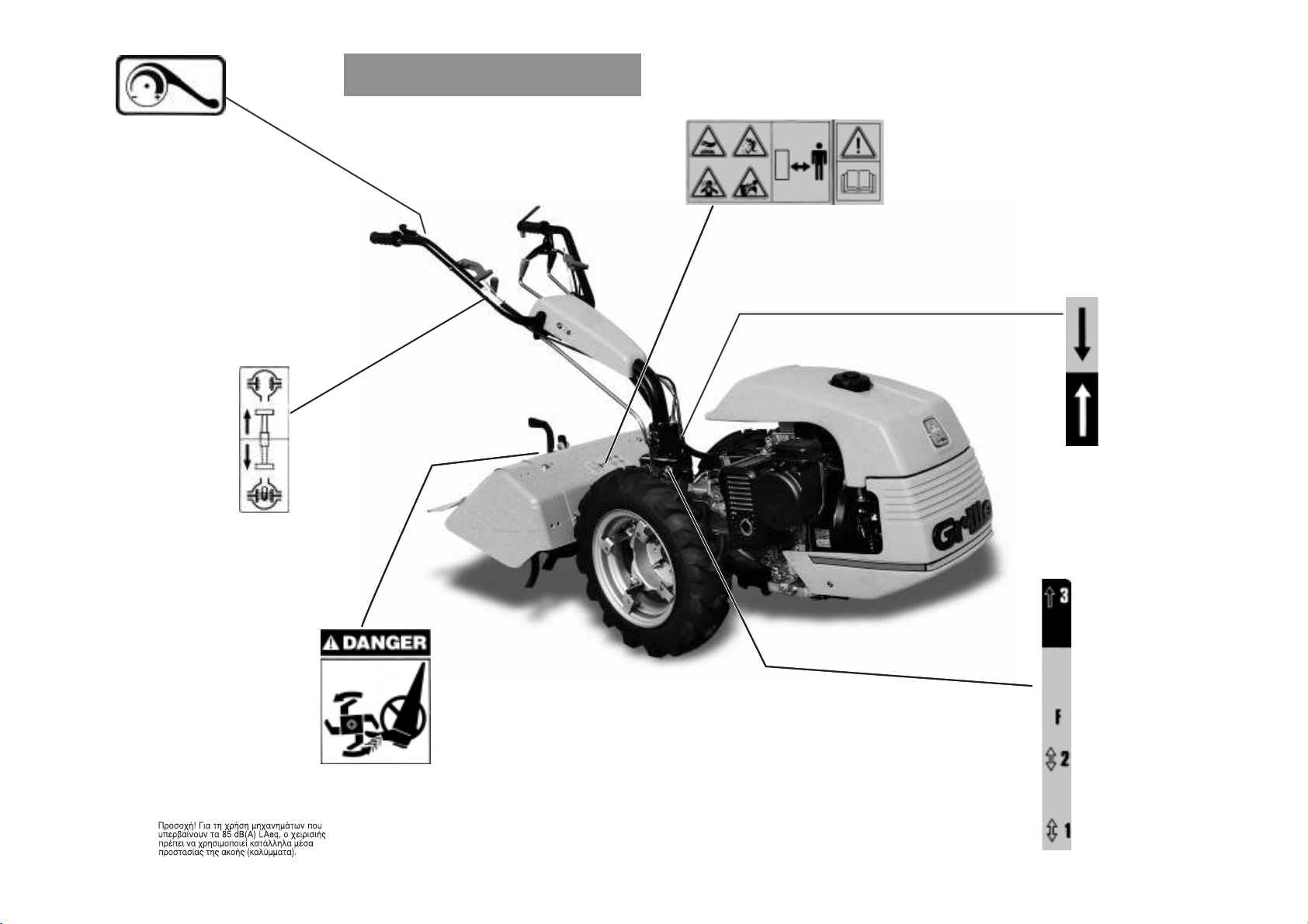
G85 G85D
GAS LEVER
– MIN + MAX
ACCELERATORE
– MINIMO + MASSIMO
ACCÉLÉRATEUR
– MIN + MAX
GASREGULIERHEBEL
– MIN + MAX
ACELERADOR
– MINIMO + MAXIMO
ACELERADOR
– MÍNIMO + MÁXIMO
ª∞¡∂∆∞ °∫∞∑π√À
– ∂§∞Ãπ™∆√ + ª∂°π™∆√
DIFFERENTIAL LOCK LEVER
FREE / LOCKED
LEVA BLOCCAGGIO DIFFERENZIALE
LIBERO / BLOCCATO
MANETTE DE BLOCAGE DU DIFFÉRENTIEL
LIBRE / BLOQUÉ
DIFFERENTIALSPERRESTANGE
FREI / GESPERRT
VARILLA BLOQUEO DIFERENCIAL
LIBRE / BLOQUEADO
ALAVANCA DE BLOQUEIO DO DIFERENCIAL
LIVRE / BLOQUEADO
ª√ç√™ ∂ª¶§√∫∏™ ¢π∞º√ƒπ∫√À
∂§∂À£∂ƒ√ / ª¶§√∫∞ƒπ™ª∂¡√
DANGER! READ THE INSTRUCTION MANUAL
KEEP SAFETY DISTANCES.
PERICOLO! LEGGERE IL MANUALE D’ISTRUZIONE
TENERE LONTANO LE PERSONE.
DANGER! LIRE LE MANUEL D’INSTRUCTIONS
RESPECTER LES DISTANCES DE SÉCURITÉ.
GEFAHR! DIE GEBRAUCHSANLEITUNG DURCHLESEN
NICHT IN DER NÄHE VON ANDEREN PERSONEN MÄHEN.
PELIGRO! LEER LAS INSTRUCCIONES
MANTENER ALEJADAS LAS PERSONAS.
PERIGO! LER O MANUAL DE INSTRUÇÕES
MANTER AS PESSOAS AFASTADAS.
∫π¡¢À¡√™! ¢π∞µ∞™∆∂ ∆√ ∂°Ã∂πƒπ¢π√ √¢∏°πø¡
ª∏¡ ∂¶π∆ƒ∂¶∂∆∂ ™∂ ∆ƒπ∆√À™ ¡∞ ¶∞∏™π∞™√À¡.
GEAR LEVER
1 / 2 GEARS
F IN NEUTRAL POSITION
3 FAST GEAR
MARCE
1 / 2 MARCE
F POSIZIONE DI FOLLE
3 MARCIA VELOCE
LEVIER DE COMMANDE DE VITESSE
1 / 2 VITESSES
F POINT MORT
3 VITESSE RAPIDE
GANGHEBEL
1 / 2 GÄNGE
F LEERLAUF
3 SCHNELLER GANG
MARCHAS
1 / 2 MARCHA
F PUNTO MUERTO
3 MARCHA RAPIDA
VELOCIDADES
1 / 2 VELOCIDADES
F PONTO MORTO
3 VELOCIDADE RÁPIDA
∆∞ÃÀ∆∏∆∂™
1 / 2
∆∞ÃÀ∆∏∆A
F
NEKPO
3
°ƒ∏°√ƒ∏ ∆∞ÃÀ∆∏∆A
DRIVE CLUTCH
INVERTITORE DI MARCIA
INVERSEUR DE MARCHE
FAHRWERK
INVERSOR DE MARCHA
INVERSOR DE MARCHA
ƒ∂µ∂ƒ™∞
G85 G85D
Warning! Turning gears, keep your hands
and feet away. Do not clean the attachment
when the engine is running.
Attenzione! Organo in rotazione, tenere
lontano piedi e mani. Non pulire l’attrezzo
col motore in moto.
Attention! Organe en rotation, ne pas
approcher mains et pieds. Ne pas nettoyer
l’outil quand le moteur est en marche.
Achtung! Rotierende klinge, Hände und Füße
fernhalten. Niemals bei laufendem Motor
reinigen.
¡Atención! Órgano en rotación, mantener
lejos los pies y las manos. No limpiar la
herramienta con el motor en marcha.
Atenção! Órgão em rotação. Mantenha as
mãos e os pés afastados. Não limpe o
equipamento com o motor em movimento.
6
Page 8
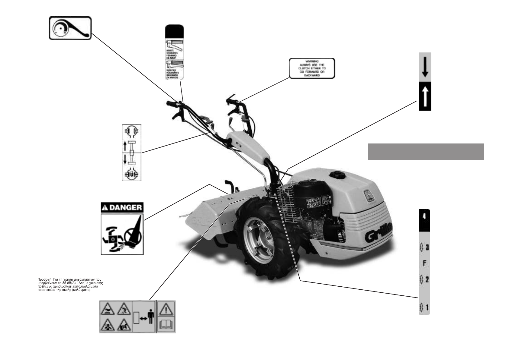
G107D
GAS LEVER
– MIN + MAX
ACCELERATORE
– MINIMO + MASSIMO
ACCÉLÉRATEUR
– MIN + MAX
GASREGULIERHEBEL
– MIN + MAX
ACELERADOR
– MINIMO + MAXIMO
ACELERADOR
– MÍNIMO + MÁXIMO
ª∞¡∂∆∞ °∫∞∑π√À
– ∂§∞Ãπ™∆√ + ª∂°π™∆√
DIFFERENTIAL LOCK LEVER
FREE / LOCKED
LEVA BLOCCAGGIO DIFFERENZIALE
LIBERO / BLOCCATO
MANETTE DE BLOCAGE DU DIFFÉRENTIEL
LIBRE / BLOQUÉ
DIFFERENTIALSPERRESTANGE
FREI / GESPERRT
VARILLA BLOQUEO DIFERENCIAL
LIBRE / BLOQUEADO
ALAVANCA DE BLOQUEIO DO DIFERENCIAL
LIVRE / BLOQUEADO
ª√ç√™ ∂ª¶§√∫∏™ ¢π∞º√ƒπ∫√À
∂§∂À£∂ƒ√ / ª¶§√∫∞ƒπ™ª∂¡√
DANGER! READ THE INSTRUCTION MANUAL
KEEP SAFETY DISTANCES.
PERICOLO! LEGGERE IL MANUALE D’ISTRUZIONE
TENERE LONTANO LE PERSONE.
DANGER! LIRE LE MANUEL D’INSTRUCTIONS
RESPECTER LES DISTANCES DE SÉCURITÉ.
GEFAHR! DIE GEBRAUCHSANLEITUNG DURCHLESEN
NICHT IN DER NÄHE VON ANDEREN PERSONEN MÄHEN.
PELIGRO! LEER LAS INSTRUCCIONES
MANTENER ALEJADAS LAS PERSONAS.
PERIGO! LER O MANUAL DE INSTRUÇÕES
MANTER AS PESSOAS AFASTADAS.
∫π¡¢À¡√™! ¢π∞µ∞™∆∂ ∆√ ∂°Ã∂πƒπ¢π√ √¢∏°πø¡
ª∏¡ ∂¶π∆ƒ∂¶∂∆∂ ™∂ ∆ƒπ∆√À™ ¡∞ ¶∞∏™π∞™√À¡.
GEAR LEVER
1/2/3 GEARS
F IN NEUTRAL POSITION
4 FAST GEAR
MARCE
1/2/3 MARCE
F POSIZIONE DI FOLLE
4 MARCIA VELOCE
LEVIER DE COMMANDE DE VITESSE
1/2/3 VITESSES
F POINT MORT
4 VITESSE RAPIDE
GANGHEBEL
1/2/3 GÄNGE
F LEERLAUF
4 SCHNELLER GANG
MARCHAS
1/2/3 MARCHA
F PUNTO MUERTO
4 MARCHA RAPIDA
VELOCIDADES
1/2/3 VELOCIDADES
F PONTO MORTO
4 VELOCIDADE RÁPIDA
∆∞ÃÀ∆∏∆∂™
1/2/3
∆∞ÃÀ∆∏∆A
F
NEKPO
4
°ƒ∏°√ƒ∏ ∆∞ÃÀ∆∏∆A
DRIVE CLUTCH
INVERTITORE DI MARCIA
INVERSEUR DE MARCHE
FAHRWERK
INVERSOR DE MARCHA
INVERSOR DE MARCHA
ƒ∂µ∂ƒ™∞
DRIVE CLUTCH LEVER
FORWARD - BACKWARD.
LEVA COMANDO INVERTITORE
AVANTI – RM (RETROMARCIA).
LEVIER INVERSEUR DE MARCHE
AVANT / ARRIÈRE.
UMKEHR-SHALTER
VORWÄRTS - RÜCKWÄRTS.
PALANCA INVERSOR MARCHA
AVANCE – MARCHA ATRAS.
ALAVANCA DE COMANDO DO INVERSOR
AVANÇAR – RECUAR (MARCHA ATRÁS).
ª√ç√™ ∂§∂°Ã√À ƒ∂µ∂ƒ™∞™
∂ª¶ƒ√™
– RM (
√¶π™£∂¡
).
G107D
ALWAYS USE THE CLUTCH EITHER TO GO FORWARD OR BACKWARD
PER L’INVERSIONE DI MARCIA USARE SEMPRE LA FRIZIONE
UTILISER TOUJOUR L’EMBRAYAGE POUR INVERSER LE SENS DE LA MARCHE
ZUR UMKEHR DER RICHTUNG DAS FAHRWERK IMMER BENUTZEN
PARA INVERTIR LA MARCHA USAR SIEMPRE EL EMBRAGUE
PARA A INVERSÃO DE MARCHA UTILIZAR SEMPRE A EMBRAIAGEM
°π∞ ∞¡∞™∆ƒ√º∏ ∆∏™ ∫π¡∏™∏™, Ã∏™πª√¶√π∂∆∂ ¶∞¡∆∞ ∆√ ™Àª¶§∂∫∆∏
Warning! Turning gears, keep your hands
and feet away. Do not clean the attachment
when the engine is running.
Attenzione! Organo in rotazione, tenere
lontano piedi e mani. Non pulire l’attrezzo
col motore in moto.
Attention! Organe en rotation, ne pas
approcher mains et pieds. Ne pas nettoyer
l’outil quand le moteur est en marche.
Achtung! Rotierende klinge, Hände und Füße
fernhalten. Niemals bei laufendem Motor
reinigen.
¡Atención! Órgano en rotación, mantener
lejos los pies y las manos. No limpiar la
herramienta con el motor en marcha.
Atenção! Órgão em rotação. Mantenha as
mãos e os pés afastados. Não limpe o
equipamento com o motor em movimento.
7
Page 9

8
ROTOVATOR
Dear Customer,
Thank you for choosing our rotovator; we are sure that your new machine’s performance will meet your
requirements in full.
To ensure optimum service and maintenance of its qualities over time, read this manual carefully and follow its
instructions. This will give you the best results and protect your investment.
Please keep this manual, which must always accompany the machine.
CAUTION! Before starting the engine, read this carefully.
The following warnings are very important in ensuring safety!
WARNINGS
Caution is your main weapon in preventing accidents!
We urge you to read the following regulations for use of the machine carefully before starting work.
Improper use of the machine and its equipment may cause damage; to reduce this risk, read the following
precautions carefully.
1) Read the whole of this manual before starting the machine or putting it in motion.
2) Pay special attention to the safety warnings and labels.
3) Rotation of the tiller is extremely dangerous; never insert hands or feet under the tiller!
4) Before other people are allowed to use the machine they must first be informed about the safety regulations
and how to use the vehicle.
5) Before starting the engine, make sure that there is no-one nearby, particularly children.
6) Never use the machine when tired and do not drink alcohol.
7) Check the ground before tilling for stones, sticks or foreign bodies which might damage the machine or be flung
dangerously to some distance during operation.
8) Before starting work, put on suitable working clothes, gloves, heavy footwear and goggles.
9) Never use the rotovator on steep slopes; it might tip over.
10) Never allow the machine to be used by anyone under 16 years of age.
11) Never reverse with the engine at high throttle.
12) It is dangerous to operate the levers sharply with the engine at maximum rpm.
13) Never keep the engine running indoors; you may inhale poisonous gases.
14) Always switch off the engine before filling up with fuel, keep away from sparks or flames and do not smoke!
15) Avoid fuel spills and after filling the tank clean all spills before starting the engine.
16) Never tamper with or disactivate the safety devices.
17) Never make any adjustments or do any cleaning with the engine running.
18) Never have anyone check the machine while you are driving with the engine running.
19) The user is always responsible for injury or damage to third parties.
20) Any improper uses causes the machine to become null and void and the constructor will decline all liability.
21) Misshapen or damaged hoes must always be replaced and never repaired.
22) Always use original Grillo spare parts.
23) Before starting any work with the machine, check that all the accident prevention systems with which it is
equipped are in perfect working order. They must never be disabled or tampered with.
24) Before starting work, check that the nuts and bolts securing the tiller and hoes are perfectly tight.
25) All protective fittings (hoods, mudguards, etc.) must be kept in place during operation.
26) Never clean the tiller with the engine running.
27) Never use the machine barefoot.
28) Do not use the fast connection or other possible extensions with the rotary hoe since they could approach
the rotary hoe to the operator’s feet and therefore not comply the security regulation PrEN 709, 1992.
29) The rotating blades of the mower are very dangerous. Never place your hands or feet under the
mower.
30) Store fuel in containers specially constructed for this purpose.
Page 10

9
IDENTIFICATION AND AFTER-SALES SERVICE
The vehicle’s serial number is punched on the nameplate on the lefthand longitudinal member of the chassis and on the gearbox
nameplate.
Always state the serial number when ordering spare parts.
31) Never change the engine settings, especially the max. rpm.
32) Allow the engine to cool before placing the machine indoors.
33) CAUTION: to reduce the risk of fire, keep the engine, the exhaust pipe and the exhaust manifolds free
from grass, leaves, dust, etc..
34) If you have to empty the fuel tank, do this outdoors.
35) Work only in sunlight or with good artificial light.
AFTER-SALES SERVICE
This handbook provides instructions for use of the cultivator and for correct basic servicing which the user can carry
out himself.
For all procedures not described in this handbook, contact your local dealer.
SPARE PARTS
Always use original spare parts, as they are the only ones to offer complete safety and interchangeability.
Always state the serial number when ordering.
For engine parts, refer to the specific handbook.
WARRANTY
The warranty conditions are as indicated on the specific warranty card.
The engine warranty conditions are those of its manufacturer.
WE ADVISE YOU TO KEEP THE FOLLOWING SPARE PARTS TO HAND
For the rotovator:
2 throttle cables
2 clutch cables
1 throttle lever
1 clutch lever
5 right-hand tiller blades with screws
5 left-hand tiller blades with screws.
For the mower bar:
5 mower bar fingers
3 blades
10 nails for single blades
1 complete blade
10 screws for fingers
2 blade couplings.
ORDERING SPARE PARTS
Always state the machine serial number and the code number of the part to be replaced.
Contact your local dealer or our own stores. Our address is:
GRILLO S.p.A.
Via Cervese 1701 - 47023 CESENA (FC) - ITALY
Tel. 0039 / 0547 / 381333 - Fax 0039 / 0547 / 632011
Web site: www.grillospa.it - E-mail: grillo@grillospa.it
Page 11

10
Gears Speeds with tyres 4.00-8
Iª 1,1
IIª 2,6
IIIª 3,6
IVª 11,4
Iª RM 1,1
IIª RM 2,6
IIIª RM 3,6
P.T.O.: independent from the gearbox; 965 rpm with engine at 3600 rpm.
Wheels: tyres 4.00-8 /4.00-10 /5.00-10.
Rotary tiller: 58 cm standard; adjustable up to 33-44-68 cm.
Handlebar: Side and height adjustment - reversible.
Track: external measurements:
with tyres 4.00-8, 43 cm
with wide steel wheels, 36-44 cm
with narrow steel wheels, 26 cm
Implements and attachments: tiller, double tiller, mower bar, snow thrower, plough, furrower, lawn mower, grass
shredder, riding sulky, irrigation pump, spraying pump, towed trailer, rotary tiller support wheel, towing bar, wheel
weights, metal wheels, weeder, container trailer, rake, front scraper, biological grinding mill, sweeper.
TECHNICAL DATA 107D
ENGINE TYPES:
LOMBARDINI 6LD400 - 15LD400
ACME A349
INTERMOTOR LGA280
Also available with electric system.
MACHINE:
Clutch: Dry, manual.
Gearbox: 7 speeds as a rotovator, 4 forward + 3 reverse.
6 speeds as a motor mower (turning the handlebars), 3 forward + 3 reverse.
Speeds in kmph with engine at 3600 rpm are as follows:
TECHNICAL DATA 126 - G85 - G85D
ENGINE TYPES:
ACME A349
INTERMOTOR 1IM350-1IM359
ROBIN EH25
YANMAR L70
LOMBARDINI 6LD400 - 15LD350
Also available with electric system.
MACHINE:
Clutch: Dry, manual.
Gearbox: 5 speeds as a rotovator, 3 forward + 2 reverse.
4 speeds as a sicklebar (turning the handlebars), 2 forward + 2 reverse.
Speeds in kmph with engine at 3600 rpm are as follows:
Gears Speeds with tyres 4.00-8
Iª 1,1
IIª 2,6
IIIª 11,4
Iª RM 1,1
IIª RM 2,6
Page 12

11
P.T.O.: independent from the gearbox; 965 rpm with engine at 3600 rpm.
Wheels: tyres 4.00-8 /4.00-10 /5.00-10.
Rotary tiller: 58 cm standard; adjustable up to 33-44-68 cm.
Handlebar: Side and height adjustment - reversible.
Track: external measurements:
with tyres 4.00-8, 44 cm
with wide steel wheels, 36-44 cm
with narrow steel wheels, 26 cm
Implements and attachments: tiller, double tiller, mower bar, snow thrower, plough, furrower, lawn mower, grass
shredder, riding sulky, irrigation pump, spraying pump, towed trailer, rotary tiller support wheel, towing bar, tank
mounted on dolly, wheel weights, metal wheels, weeder, container trailer, rake, front scraper, biological grinding
mill, sweeper, trailer with driving wheels.
INSTRUCTIONS FOR USE
Before starting the engine always check:
– The oil levels inside the engine (fig. 5) and the gearbox; the level check cap is on the upper cover (fig. 6); the
oil level must be between the two notches.
– That all screws and nuts are well tightened especially those fastening the attachments to the machine.
– That all levers are in neutral.
– That the air filter (dry version) is clean (fig. 7). Caution! Never blow the cartridge with compressed air; if clogged
it must be replaced.
– That the air filter (in oil bath version) is clean and its oil at the right level (fig. 7A).
– That there is a little slack on the clutch cable (fig. 8).
PUTTING THE MACHINE INTO SERVICE
1) Check that the machine has not been damaged in transit.
2) Fill with grease the machine PTO flanging all around the coupling (fig. 3A no. 20).
3) Select driving handlebar position according to the use, Walking tractor or Motormower, by using the two levers
(fig. 3A no. 10 and no. 12).
4) Mount wheels and implement (e.g. rotary tiller, plough etc.) and tighten the securing nuts completely.
5) Add engine oil, please refer to attached instruction booklet.
6) Check the gearbox oil - fig. 6 (MP 80W 90 oil, international equivalent API GL5 oil, US MIL-L-2105D, quantity
2,2 litres for G85 and 1,9 litres for G85D and G107D).
7) Add oil into the air filter in oil bath (for versions provided with this type of filter), use the same oil type as the
engine oil (fig. 7A).
8) Insert the control levers (fig. 3A no. 13 and no. 15).
9) Verify the tyre pressure according to the table provided.
TIRE PRESSURE
4.00 - 8 2 PLY RATING 1,1 BAR
4.00 - 10 2 “ “ 1,1 “
5.00 - 10 2 “ “ 1 “
5.00 - 12 2 “ “ 1,5 “
10) In the electric starting versions verify the battery voltage, it must not be lower than 12V, when required charge
the battery.
When the battery has been supplied dry with the acid separate, to put the battery into service it is necessary:
a) to add acid into the battery and wait 2 hours;
b) to charge the battery with a battery recharger set at 12V on slow charge for 2 hours. Warning, failure to follow
this rule may cause deterioration of the battery and acid leaks during the operation.
IMPORTANT!
During assembly take care not to get the polarity of the battery reversed.
11) Check the clutch wire has a 3/5 mm clearance between the regulator and the lever.
12) Fill the tank with fuel using a funnel provided with a fine filter.
13) Check liquid levels when the machine is horizontal.
Page 13

12
– Check the oil level inside the tiller gearbox (fig. 4A no. 3).
– Fill the tank with fuel, using a funnel with very fine filter.
Once the engine has started, release the choke (petrol engine version) and increase speed progressively.
Let the engine warm up for some minutes before starting work.
STARTING THE PETROL ENGINE
Connect the engine stop (fig. 3A no. 25). Turn on the petrol cock, push the throttle lever to the midway position and,
if the engine is cold, engage the choke on the carburetor. Start the engine by pulling hard on the pull starter handle
(6, Fig. 4A).
STARTING THE DIESEL ENGINE
Connect the engine stop (fig. 3A no. 25). Push the throttle lever to the midway position (see engine manual), press
the decompressor lever on the engine head until it remains in position and start the engine by pulling hard on the
pull starter handle (6, Fig. 4A).
STARTING THE MACHINE
Engage the clutch and set the gearbox lever in the desired position. If the gear does not engage immediately, give
a few light touches on the clutch. Release the clutch lever slowly until the machine starts moving.
N.B. - If the P.T.O. is connected the reverse gear cannot be inserted. Disengage the P.T.O. and then engage
the reverse gear.
STARTING WORK
Engage the clutch and connect the P.T.O., moving the clutch lever slightly if it does not engage at once. Increase
speed as appropriate and release the clutch to start work.
END OF WORK
When work is ended, in order to stop the engine, set the gear and P.T.O. in neutral position and leave the handles,
cloese the fuel tap.
If your rotovator is fitted with an electric starter you must also turn the ignition key off.
TROUBLESHOOTING
The following is a list of small problems which may occur during the use of the rotovator, which the operator himself
can remedy.
1) if the petrol engine does not start, check as follows:
– that the fuel tank is at least half full;
– that the petrol cock is turned on;
– that the choke is engaged (when the engine is cold);
– that fuel is reaching the carburetor;
– that the vent hole on the fuel tank is not blocked;
– that the mesh filter at the carburetor intake is clean;
– that the carburetor jets are clean. Check by unscrewing them and if dirty, clean them with a jet of air;
– that spark plug is generating a spark. To check this, remove the spark plug, re-connect it to the electricity supply
wire, rest the metal side on an electrical earth and turn the engine-pulley as if to start it. If no spark is seen
between the electrodes, check the connection of the spark plug cable; if there is still no current replace the spark
plug with a new one. If a spark is still not obtained, the problem is in the electric system: points, capacitor, coil,
or in some other component. Contact your nearest service centre or a specialist workshop.
2) if the Diesel engine does not start check as follows:
– that the fuel tank vent hole is not blocked;
– that the fuel tank is at least half full.
If the ambient temperature is very low, fill the rubber-capped sump over the engine with oil.
If the engine still does not start, vent the air from the fuel lines, following the directions in the engine operator’s
manual.
If the engine still does not start, contact your nearest service centre or a specialist workshop.
3) If the gears do not engage:
– regulate the clutch by unscrewing the adjuster screw until the clutch release distance is satisfactory. Remember
that there must always be a little slack on the clutch cable.
Page 14

13
4) Rotovator with mower bar or motor mower:
– if the blade coupling (3, fig. 15) breaks frequently check that the ledger plates are not too tight.
5) Check if the ground is stony; if so pull down the cutting height regulator slides to raise the mower bar, so that
small stones cannot become jammed between the fingers and blades. The cut grass should be discharged to
the front and not to the sides.
– if the grass is very thick and the mower has difficulty discharging it, remove the skids.
Naturally, in these conditions the mower will no longer form two windrows either side of its path and the cut grass
must be separated from the grass to be cut by hand, in order to avoid further obstructions. The Mulching or Tirol
mower bar is recommended in these circumstances, since it avoids such problems.
FOR LONG IDLE PERIODS
In case the machine is not to be used for a long period, the following precautions are recommended:
– empty the fuel tank and the carburetor;
– drain the oil from the engine;
– clean the engine and the machine thoroughly. Oil the handlebar support reversing mechanism.
MAINTENANCE AND LUBRICATION
Proper maintenance and lubrication help to keep the machine constantly in perfect working order.
RUNNING-IN: change the engine oil after the first twenty working hours.
ENGINE - Follow the instructions on lubrication intervals in the relative manual.
In general users are advised to check the oil level every 4 working hours and to change it every 50 hours. Always
use 15W40 engine oil. Check the air filter oil level every 8 working hours or more often in very dusty conditions.
Top up with the same oil as for the engine (see engine handbook). On versions with dry filter, replace the cartridge
if clogged (do not clean with compressed air jets).
GEARBOX - Check the oil level every 50 working hours by removing the cap and checking with the machine
horizontal the oil reaches between the two notches. If necessary add MP 85 W/90 oil.
Change the oil once a year.
ROTARY TILLER - Check the oil level every 50 hours by removing the plug; the oil must almost fill the rotary tiller
box. If necessary add the same oil as for the gearbox.
HELPFUL HINTS FOR PROPER USE:
1) Important! Always use the clutch for forward and reverse travel.
2) Never keep the clutch disengaged for long periods.
3) Never leave the out in the rain.
4) Keep the reversing mechanism in the handlebar support clean and well oiled.
5) Never force the gearbox if the gear does not engage; give a succession of little touches on the clutch.
6) Never strain the engine: if smoke comes out of the exhaust, the engine is toiling and must be slowed down.
7) Even impossible ground can be tilled, but the machine must be well run-in first.
8) Never work at full throttle.
9) If the engine overheats on the first day, it must be stopped for a few minutes’ rest.
10) Check the tyre pressure often.
11) When fitting the implements (e.g. rotary tiller) take care not to damage the centring device (see chapter on
«Implements»).
END OF SEASON MAINTENANCE
Clean the machine carefully; change the engine, gearbox and tiller gearbox oil. Clean the air filter.
Sharpen and grease the blades, replacing them if worn.
If parts have been broken and screws lost during the season, now is the time to restore everything to perfect working
order.
Place two planks under the wheels.
Never keep the machine in animal sheds or near to chemical fertilizers, as this could cause certain parts to rust.
Page 15

14
I M P L E M E N T S
ROTARY TILLER
The rotary tiller is used to break the surface layer of the ground in order to increase its permeability and at the same
time to rid of weeds.
Till in first speed if the soil is hard and tough or in second speed in soft, sandy soil.
The working depth can be adjusted by lifting or lowering the central knife situated under the rotary unit. The tiller
cover position will change at the same time. Raise the knife to increase the depth. Start work with the knife in its
lowest position, and then raise it if greater depth is required.
N.B. - On hard soils the machine may jump forward. In this case lower the central knife and fit it into the
third hole. Check that the blades are fitted correctly (see fig. 9).
ADJUSTABLE FURROWER
This implement is specially designed for preparing furrows for sowing and irrigation. It is mounted like a plough or
a rotary tiller on the implement flange on the back of the gearbox.
The furrow width can be regulated from a minimum of 10 cm to a maximum of 30 cm, by changing the position of
the two wings.
The depth can be varied from 10 to 20 cm. When working on particularly hard soils, till before furrowing. The results obtainable
can be improved by fitting the 5.00-12 tyres and if necessary the wheel-weights which increase wheel grip (fig. 10).
COMBINED FURROWER
Like the adjustable furrower, this implement is used for preparing furrows for sowing and irrigation, but it is mounted
above the rotary tiller instead of the tiller cover, and the two implements work together. The traction provided by
the wheels is increased by the propulsive action of the rotary tiller (working on the ground), for easier forward
movement even on particularly hard soils.
To use the combined furrower, remove the tiller cover and the outside blade flanges, reducing working width to 30
cm (8 blades).
The furrower height can be adjusted using the rear support rod which has several holes. The furrow depth can also
be varied by changing the mounting position. The width can be adjusted by changing the position of the two back
wings (fig. 11).
RIDING SULKY
This is a useful way of reaching the working place quickly and effortlessy. It can be attached without removing the
rotary tiller and can then be disconnected rapidly once you reach the work site.
The sulky can be attached to the machine by fitting a curved bar to the machine itself (see relative chapter) and
connecting it with the pivot provided.
Maintenance: grease the wheel-bushings periodically by removing the wheels and filling the space between the
two bushings with grease (fig. 12).
MOWER BAR
The mower bar which can be attached to the rotovator has a central or side control. Its strength and high
performance make it the best way of mowing small pieces of land when it does not make economic sense to
purchase a motor mower which would remain unused for most of the year, while a rotovator can be used with other
implements.
The mower bar is attached to rotovator implement frame instead of the rotary tiller and fixed using the same two
nuts. The handlebar must be turned 180° towards the engine.
Before turning the handlebar engage first gear, then release the drive rods.
Once the handlebar has been turned, fit the rods back into the supports.
Now that the handlebar has been reversed the handlebar support mechanism enables the use of all the rotovator
gears, except the fastest speed which could be dangerous.
To drive the mower bar, disconnect the safety device which prevents simultaneous engagement of the reverse
speed and the P.T.O. (necessary when using the rotary tiller) by simply removing the screw that blocks the gear
lever and stops the engagement of the two functions together.
Important: when reconnecting the rotary tiller, the safety device must be set in the original position. We
do not accept any responsibility for failure to follow this rule (fig. 2 and fig. 2/A).
Maintenance: grease the cross pins every 8 working hours through the grease nipples on the swinging crank.
Grease the mower bar swinging bushing every 50 working hours through the grease nipple under the swinging
protection.
Keep the blade ledger plates properly adjusted. They must be neither too tight, so that they block the blade, nor
too loose so that there is too much clearance between them and the blades. To adjust the ledger plates in both
directions loosen the locking bolts (fig. 13-14) and adjust the pressor screw. The ledger plates should be replaced
Page 16

15
when worn even if they are still able to apply pressure against the blades.
Regulate the clearance between the blade and the strip by loosening the screws fixing the plates pressing the strip
and moving the strip forward until it touches the bar which supports the nailed blade section. Then retighten the
pressing plates.
To remove the blade take off the L-shaped blade coupling by removing the two screws (fig 15 no. 3) and slip off
the blade. Take care to tighten the fixing screws of the coupling after assembling the blade again.
Always use sharp blades: the machine will be subject to less strain and its working life will be longer.
Clean the mower bar after every working day, removing any remaining pieces of grass or earth; every now and then
check that all screws are tight.
SNOW THROWER
This implement has been especially designed for this particular rotovator. It is very useful for clearing snow from
yards, driveways, etc. It consists of a turbine rotary unit enclosed in a special case open at the front, which rotates
at high speed, collecting the snow and throwing it along a pipe. The pipe angle can be adjusted to throw the snow
in any direction to a distance of 8 - 10 metres.
The snow thrower is fixed to the implement flange using two nuts. The handlebar must be turned through 180°
towards the engine; for this operation follow the directions given for the mower bar.
To operate the snow thrower, the safety device preventing simultaneous engagement of reverse gear and the
P.T.O. (necessary with the rotary tiller), must be disconnected by removing the allen screw on the PTO lever.
Important: when reconnecting the rotary tiller, the safety device must be set in the original position. We
do not accept any responsibility for failure to follow this rule.
The snow thrower is 70 cm wide and can clear snow up to 40 cm deep. Wheel weights should be used for best
performance.
If the snow is very wet, keep the ejection pipe turned forward to avoid obstructions at the outlet. The two side skids
must be adjusted so that they just skim level ground (asphalted streets) or keep the snow thrower high if the ground
is uneven (fig. 16).
Maintenance: when work is over, remove any snow left in the snow thrower so it cannot freeze and block the
turbine.
ATTENTION:
While attaching the different implements to the flange, make sure that the two parts are perfectly aligned. The nuts
of the two stud-bolts must be screwed on by hand and then using a wrench so that they apply pressure to the flange
simultaneously.
PLOUGHS
The ploughs designed for this rotovator have been especially developed to obtain good ploughing without overstraining the operator.
The models available are a single-share plough and a 180° roll-over plough. The latter is especially suitable when
working backwards and forwards, such as along rows of vines or fruit-trees.
The depth of the furrow obtained may vary from 10 to 15 cm depending on the terrain.
The use of steel wheels is recommended (fig. 17).
ROTARY CUTTER
The rotary blade rotary cutter cm. 75 for the rotovator (fig. 18) is designed for the maintenance of grounds with
too high grass.
The high power available, the driving wheels, the working speeds and the reverse gear allow operation in the most
difficult conditions without tiring the operator and with considerable time saving.
The rotary cutter is fixed to the implement flange using two nuts. It is supplied with the lateral rams for hard
conditions, or with front support wheels in order to use it with low grass and levelled soils. The handlebar must be
turned through 180° towards the engine; for this operation follow the directions given for the mower bar. The blade
is driven by means of a bevel gear pair and is equipped with a release mechanism so that its force of inertia cannot
drag the machine forward when the clutch is engaged.
To adjust the cutting height vary the position of the rotary cutter wheels, or of the lateral rams.
A version with grass bin is also available.
Maintenance: Keep the lawn mower blade well sharpened: the cut will be better and the engine will not strain.
Always tighten the two fixing bolts well when fastening or removing the blade. Often check the two nuts fixing the
lawn mower to the machine frequently.
Check the gearbox oil level every 50 hours, removing the cap on the top, and make sure that the oil level is within
50 mms of the hole; if the level is lower add 80W/90 gearbox oil.
Change the oil once a year.
Page 17

16
TOWED TRAILER
The trailer designed for the rotovator is very useful for short hauls around the farm. It is easy to handle, compact
and very quickly hitched to the rotovator.
The trailer can be attached directly to the machine by hitching it to the special towing bar (fig. 19) leaving the tiller in place.
IRRIGATION PUMP
A small centrifugal pump can be fitted to irrigate small areas of land. It can be attached directly to the flange of the
machine and is inserted using the same lever as the rotary tiller (fig. 20).
SPRAYER PUMP
This pump can be attached in the same way as the irrigation pump.
It is very useful for market gardeners and for spraying intensive crops (fig. 21).
WHEEL-WEIGHTS
These are mounted on the wheel rims and fixed with two of the four nuts which fix the wheels themselves. They
increase the weight of the machine and thus its grip, and their use is recommended when working with the plough,
the adjustable furrower, and even the rotary tiller and the trailer if special performances are required. They weigh
10 Kg. each (fig. 22).
SNAP COUPLING
The snap coupling is designed to allow various implements to be hitched to the machine easily; the implement is
disconnected by simply pulling a lever, without the aid of spanners. This accessory consists of two parts, one fixed
to the machine and the other to the implement. Users are therefore advised to purchase just one piece for the
machine, and one for each implement (fig. 23). Grease every 50 hours.
It can be of two types: 50 mm. and 60 mm.
TOWING BAR
The towing bar is needed to attach the riding sulky or the trailer to the machine without removing the rotary tiller.
This attachment must be fastened to the towing hook on the rotovator (fig. 24).
ROTARY TILLER SUPPORT WHEEL
It is very useful while travelling between jobs, because it keeps the rotary tiller off the ground, making transfer easier
and less tiring (fig. 25).
ALL PURPOSE FLAIL
It is 68 cm wide, has a roller fitted with swinging y tines and is able to cut tall grass, tough stalks and small shrubs
into fine pieces; it can also twigs etc. after pruning. Used with mower blades instead of the y tines, it gives excellent
results on smooth lawns (fig. 26).
WHEEL EXTENSIONS
These help to widen the machine’s track and increase its stability on crosswise slopes. They must be fixed between
the wheels and the hubs. The track is widened by 6 cm on each side (fig. 27).
WIDE STEEL WHEELS
These wheels are particularly advisable when working on very hard soils with the rotary tiller.
The cross bars placed around the wheels dig into the ground, giving the machine a firm grip and preventing the
wheels from skidding (fig. 28).
The wide steel wheels can be also used when tyres or the narrow steel wheels, might skid or sink in damp or recently
tilled ground. The use of wide steel wheels is recommended, although only in these cases.
Otherwise tyres are generally advisable; if special grip is not required, they give the machine more even traction
and form an elastic buffer between the machine and the ground.
Twin rings are also available for fitting to these wheels.
ADJUSTABLE WHEELS SPACERS
These innovative screw spacers are advisable above all for the ploughing.
If you have to change the track gauge, please unlock the two keys kept by the springs, start the machine, put the
first gear, block the differential lock and release the clutch when the engine is at minimum; in this way the track
gauge is automatically changed.
Attention, not to unscrew them completely. Position the keys and respective springs another time.
Now you can change the track gauge, lifting the machine and operating manually (fig. 29).
Page 18

17
BACK-CUTTER FURROWER
This tool is mounted at the rear of the tiller and works in tandem with it. the furrower is designed to produce irrigation
and seed drills (figure 30).
TRAILER WITH DRIVING WHEELS FOR 127D AND 107D
The application of this trailer converts the rotovator into an efficient mini tractor (fig. 32) with four wheel drive,
steering wheel and tipping trailer bed. Hitching the trailer to the machine is extremely easy thanks to the snap
coupling which allows the mini tractor to be prepared in just a few minutes (fig. 31).
Wheels 5.00-12
2 ply - rating 0.90 bar front
4 ply - rating 1.70 bar rear
SIDE-DELIVERY RAKE - 120 cm
The side-delivery rake for engine-driven cultivators is mounted on the implement flanging. The implement is
equipped with a lever to make steering easier (figure 32). Designed for turning hay or making swathes.
TILTING FRONT DOZER BLADE - 85 cm
This highly resistant device is ideal for removing snow and levelling mounds of soil or gravel. May be tilted to the
right and left (figure 33).
ROTARY MOWER
The rotary mower is available with one or two disks. The model with two disks forms swathes of the product while
the single disk version spreads it. Suitable for mowing forage or cutting weeds (figure 34).
TRAILER
The trailer is mounted on the tool flanging. It is equipped with a dumper and reversible wheels to make steering
easier (figure 35).
BIOSHREDDER
Designed to shred prunings and plant waste. Equipped with a clipper to cut branches up to 3-4 cm in diameter (figure 36).
TILTING SWEEPER - 100 cm
The device is used to clean squares, alleyways and pavements; the machine moves material to the side instead
of forward. May also be used for snowploughing (figure 37).
Page 19

Page 20

Fig. 2
Sicklebar - Motofalciatrice - Motofaucheuse - Motormäher
Motosegadora - Motosegadeira - ГФЪИФОФЩИОФ
Walking tractor - Motocoltivatore - Motoculteur - Einachsschlepper
Motocultor - Motocultivador - ªФЩФЫО·ЩИОФ
Fig. 2A
59
Page 21

Page 22

To unlock the clutch (and the differential lock in the G85D model), please press the small
lever situated under lever A (see image above).
Per sbloccare la frizione (ed il differenziale nel G85D) agire sulla levettina posta sotto la leva
rif. A.
Pour débloquer l’embrayage (et le differentiel pour le modèle G85D), il faut appuyer sur le
petit levier au-dessous du levier A (regarder l’image au-dessus).
Bitte wirken Sie des Hebels ein, der unter dem Hebel Abb. A liegt, um die Kupplung (und die
Differentialsperre für G85D) zu entsperren.
61
Page 23

Page 24

Page 25

Page 26

Page 27

Page 28

Page 29

Page 30

Page 31

Page 32

 Loading...