


ACNF
1
ACNF CEILING MOUNT AIR HANDLER
INSTALLATION INSTRUCTIONS
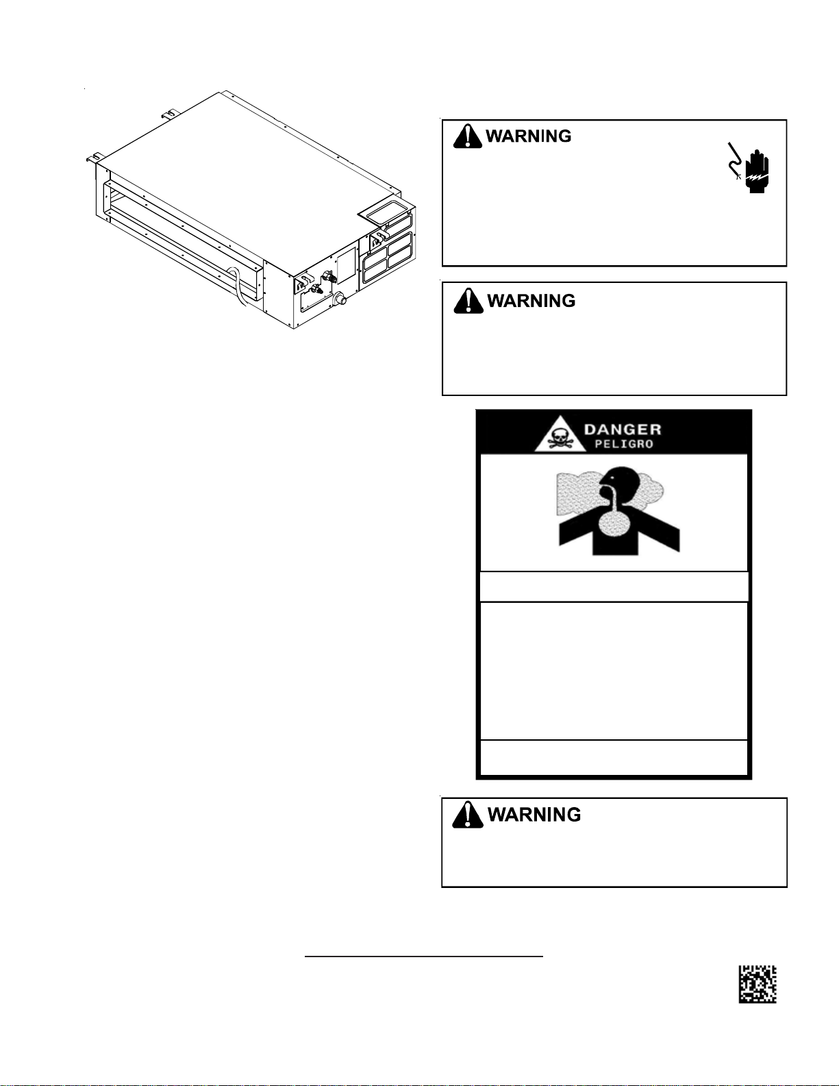
Important Safety Instructions
The following symbols and labels are used throughout this
manual to indicate immediate or potential safety hazards. It
is the owner’s and installer’s responsibility to read and com-
ply with all safety information and instructions accompany-
ing these symbols. Failure to heed safety information in-
creases the risk of personal injury, property damage, and/or
product damage.
Codes & Regulations
This product is designed and manufactured to comply with
local, national and international laws, codes and regulations.
Installation in accordance with such codes and/or prevailing
local codes/regulations is the responsibility of the installer.
The manufacturer assumes no responsibility for equipment
installed in violation of any codes or regulations.
HIGH VOLT AGE!
D
ISCONNECT
ALL
POWER
BEFORE
SERVICING
OR
INSTALLING
THIS
UNIT
. M
ULTIPLE
POWER
SOURCES
MAY
BE
PRESENT
. F
AILURE
TO
DO
SO
MAY
CAUSE
PROPERTY
DAMAGE
,
PERSONAL
INJURY
OR
DEATH
DUE
TO
ELECTRIC
SHOCK
.
W
IRING
MUST
CONFORM
WITH
NEC
OR
CEC
AND
ALL
LOCAL
CODES
. U
NDERSIZED
WIRES
COULD
CAUSE
POOR
EQUIPMENT
PERFORMANCE
,
EQUIPMENT
DAMAGE
OR
FIRE
.
G
OODMAN
WILL
NOT
BE
RESPONSIBLE
FOR
ANY
INJURY
OR
PROPERTY
DAMAGE
ARISING
FROM
IMPROPER
SERVICE
OR
SERVICE
PROCEDURES
. I
F
YOU
PERFORM
SERVICE
ON
YOUR
OWN
PRODUCT
,
YOU
ASSUME
RESPONSIBILITY
FOR
ANY
PERSONAL
INJURY
OR
PROPERTY
DAMAGE
WHICH
MAY
RESULT
.
CARBON MONOXIDE POISONING HAZARD
-
Special Warning for Installation of Furnace or Air Handling Units in
Enclosed Areas such as Garages, Utility Rooms or Parking Areas
Carbon monoxide producing devices (such as an automobile, space
heater, gas water heater, etc.) should not be operated in enclosed areas
such as unventilated garages, utility rooms or parking areas because of
the danger of carbon monoxide (CO) poisoning resulting from the exhaust
emissions. If a furnace or air handler is installed in an enclosed area such
as a garage, utility room or parking area and a carbon monox i de produc ing
device is operated therein, there must be adequate, direct outside
ventilation.
This ventilation is necessary to avoid the danger of CO poisoning which
can occur if a carbon monoxide producing device continues to operate in
the enclosed area. Carbon monoxide emissions can be (re)circulated
throughout the structur e if the furnace or air handle r is operating in any
mode.
CO can cause serious illness including permanent brain damage or death.
B10259-216
T
O
PREVENT
THE
RISK
OF
PROPERTY
DAMAGE
,
PERSONAL
INJURY
,
OR
DEATH
,
DO
NOT
STORE
COMBUSTIBLE
MATERIALS
OR
USE
GASOLINE
OR
OTHER
FLAMMABLE
LIQUIDS
OR
VAPORS
IN
THE
VICINITY
OF
THS
APPLIANCE
.
© 2011 Goodman Manufacturing Company, L.P.
5151 San Felipe, Suite 500, Houston, TX 77056
www.goodmanmfg.com -or- www.amana-hac.com
IO- 422
10/2011
SHIPPING INSTRUCTIONS ..................................................... 2
APPLICATION INFORMATION ................................................... 2
P
RE-INSTALLATION CONSIDERATIONS ...................................... 2
INSTALLATION ORDER .......................................................... 3
LAYOUT FOR CEILING MOUNT AIR HANDLERS ......................... 3
OUTDOOR UNIT INSTALLATION ............................................... 9
INSTALLING THE CONNECTING PIPE ...................................... 10
REFRIGERANT PIPE CONNECTION ........................................ 11
CONNECTING THE AIR HANDLER TO THE OUTDOOR UNIT ......... 12
CONNECTING THE DRAIN PIPE - INDOOR UNIT ....................... 12
UNITS WITH FRESH AIR DUCT INSTALLATION ......................... 14
MOTOR AND DRAIN PUMP MAINTENANCE ............................. 14
ELECTRICAL WIRING ........................................................ 14
TESTING THE UNIT’S OPERATION ......................................... 15
WIRING DIAGRAMS ........................................................... 18
2
Do not connect to or use any device that is not design
certified by Goodman for use with this unit. Serious
property damage, personal injury, reduced unit
perform ance and/O R haza rdou s cond itio ns m ay resu lt
from the use of such non-approved devices.
WARNING
Have your contractor identify all the various cutoff switches
and devices that service this unit. Know where the switch is
that will cut off energy to the heating system in the event of
overheating.
CAUTION
Special Notes for European Consumers:
Do not dispose of this product as unsorted municipal waste.
Collection of such waste for special treatment is necessary.
It is strictly prohibited to dispose of this unit in domestic
household waste. Disposal options:
1. Some municipalities have established collection systems
to collect electronic waste for disposal.
2. Your purchase point retailer (or manufacturer) may take
back the unit for disposal.
3. Used products contain valuable resources and can be
sold to scrap metal dealers.
Illegal disposal in forests and landscapes endanger your
health and the environment. Hazardous materials leak into
ground water.
SHIPPING INSPECTION
Upon receiving the product, inspect it for damage from ship-
ment. Shipping damage, and subsequent investigation is the
responsibility of the carrier. Verify the model number, speci-
fications, electrical characteristics, and accessories are cor-
rect prior to installation. The distributor or manufacturer will
not accept claims from dealers for transportation damage or
installation of incorrectly shipped units.
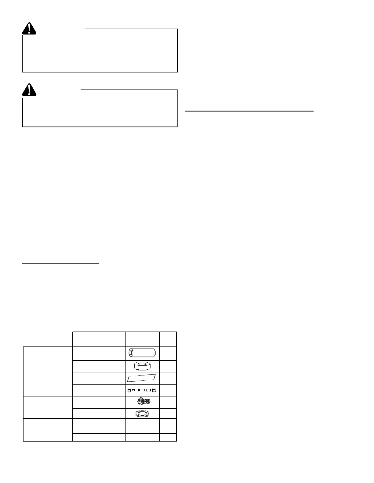
Name Shape Qty.
Soundproof/
Insulation sheath
2
Binding Tape 1
Seal Sponge 1
*Orifice 1
Drain joint 1
Seal ring 1
Wire controller
Wire controller
---
1
Owner's Manual
--- 1
Installation Manual
--- 1
* As applicable
Tubes
&
Fittings
Drain Pipe
Fittings for
cooling/heating
Literature
APPLICATION INFORMATION
This ceiling mount air handler is available in cooling capaci-
ties of 1.0, 1.5, 2, 2.5, 3.0, 3.5, 4.0 and 6.0 nominal tons of
cooling. Electric heat models are available in capacities of 0,
5, 6, 8 and 10 kW.
The unit is designed to be installed in a horizontal position
above a dropped ceiling. Do NOT install this unit outside
the structure. These models are designed for INDOOR
USE ONLY.
PRE-INSTALLATION CONSIDERATIONS
Carefully read all instructions for the installation prior to in-
stalling product. Make sure each step or procedure is under-
stood and any special considerations are taken into account
before starting installation. Assemble all tools, hardware
and supplies needed to complete the installation. Some items
may need to be purchased locally. Make sure everything
needed to install the product is on hand before starting.
Before attempting any installation, the following points should
be considered:
• Structural strength of supporting members
• Clearances and provision for servicing
• Power supply and wiring - Routing of wires must be
arranged so the control board cover is fixed properly.
If not, a possibility of overheating, fire or electrical
shock may occur at the connection point of the termi-
nal.
• Air duct connections - Ductwork should be fabricated
in accordance with local codes and sized to accom-
modate 375-425 CFM per ton of cooling with the static
pressure not to exceed 0.5” W.C. Inadequate ductwork
that restricts airflow can result in improper performance
and compressor or heater failure.
• Drain facilities and connections
• Installation of unit must be, at a minimum, of 91” (2.3m)
above the floor.
• Electrical installations must be in accordance with lo-
cal national wiring standards, regulations and this in-
stallation instruction. An independent circuit and single
outlet must be used. If installed without the proper
electrical circuit capacity, or installed defectively, pos-
sibility of electrical shock or fire may occur.
• To ensure proper performance of unit, use the speci-
fied cable, and clamp the cable securely to prevent
disconnection as this will cause overheating or fire at
the connection.
• An all-pole disconnect switch, having a contact sepa-
ration of at least 3mm in all poles, should be con-
nected in the fixed wiring.
3
8” (200mm)
or more
12” (300mm)
or more
24” x 24”
(600mm x 600mm)
(Checking orifice)
Figure 1 - Room clearances
NOTE: To prevent interference, keep indoor unit, outdoor
unit, power supply wiring and transmission wiring at
least 39” (1 meter) from televisions and radios.
INSTALLATION ORDER
Install your unit in the following order:
1. Select the mounting locations.
2. Install the indoor unit.
3. Instal the outdoor unit.
4. Install the connecting pipe
5. Connect the drain pipe.
6. Wiring.
7. Test operation.
LAYOUT FOR CEILING MOUNT AIR HANDLERS
NOTE: The location of the unit is based on thorough consid-
eration of the PRE-INSTALLATION CHECK POINTS below:
• Structural strength of supporting members
• Clearances and provision for servicing
• Power supply and wiring
• Air duct connections
• Drain facilities and connections
1. Before locating the unit on the dropped ceiling, ensure
the strength of the ceiling and beams is adequate to
support the weight involved. This is an important step
and the installers responsibility.
Installing the four (4) 3/8” (Ø 10) Hanging Screw Bolts
2. Mount the unit in a horizontal position above a dropped
ceiling of adequate strength with four 3/8” (Ø 10) hang-
ing screw bolts. Refer to the following figures for dis-
tance between the screw bolts.
3. The installation to ceilings varies with construction. Con-
sult construction personnel for the specific procedures.
4. Install pipes and lines in the ceiling after completion of
the installation of the ACNF air handler. The first con-
sideration of installation is to determine the direction of
the pipes. When installing in a ceiling, position the re-
frigerant pipes, drain pipes, indoor and outdoor lines to
the connections before hanging the unit.
5. Install the hanging screw bolts.
6. After the selection of installation location, position the
refrigerant pipes, drain pipes, indoor and outdoor lines
to the connections before hanging the unit.
7. Attach the hanging screw bolts.
NOTE: The minimum drain tilt is at least 1/100.
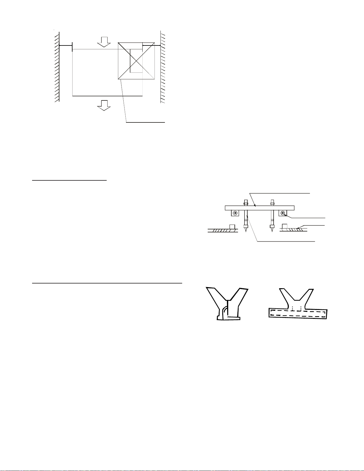
Wooden construction
Put the square timber traversely over the roof beam, then
install the hanging screw bolts.
Timber over the beam
Ceiling
Hanging Screw Bolts
Roof Beam
Figure 2
New Concrete or Bricks
Embedding the screw bolts, Figure 3.
Slide
Insertion
Blade Shape
Insertion
Figure 3
Installation for Existing Concrete Bricks
Use embedding screw bolt, crock and stick harness as shown
in Figure 4.
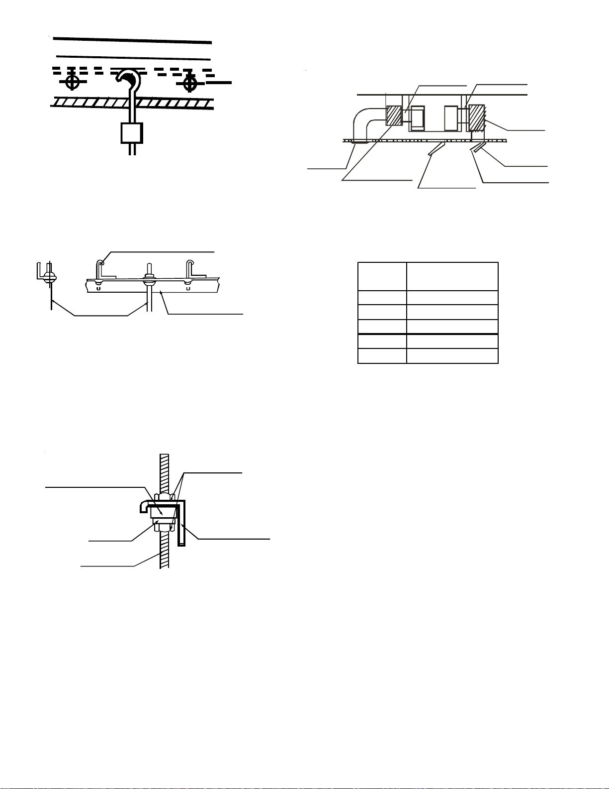
4
Steel Bar
Embedding screw bolt
(Pipe hanging & embedding screw bolt)
Figure 4
Steel Room Beam Structure
Install directly on the supporting angle steel. See Figure 5.
Hanging Bolts
Hanging Screw Bolt
Hanging Bolts
Supporting Angle Steel
Figure 5
Hanging the Indoor Unit
1. Place the indoor unit onto the hanging screw bolts with
block.
2. Using a level, position the unit to hang flat to prevent
leaks, Figure 6.
Screw Nut
Overhang
Shock-proof cushioningShock-proof cushioningShock-proof cushioning
Hanging Screw Bolt
Washer
Figure 6
Installing the dust proof net and canvas air passage
1. Install the dust proof net according to the installation
manual.
2. Install the canvas air passage underneath the dust proof
net.
Duct Design
1. Air inlet/outlet ducts must be spaced to prevent air from
the outlet from entering the air inlet.
2. A dust filter is located on the indoor unit.
Recommended duct connections:
Canvas tie-in
Canvas tie-in
Air inlet
Isolation
booth
Checking
orifice
Air dust filter
Isolation
booth
Air
outlet
Figure 7
3. It is important to maintain the static pressure below to
alleviate excessive noise, blowing water or other abnor-
malities.
Model
(Kw)
Static Pressure
Inches H
2
0 (Pa)
12 0.16 (40)
18 0.28 (70)
24 0.28 (70)
30-36 0.32 (80)
42-60 0.40 (100)
NOTES:
1. The indoor unit should not bear the connecting duct’s
weight.
2. Use the fire retardant canvas tie-in to prevent vibrating.
3. When connecting the ductwork, install in a location
where maintenance can be done easily.
4. The fan motor static pressure should correspond to the
external static pressure.
5. When installed in a noise-sensitive setting, install an
isolation booth and internal duct underlayer to help muffle
the duct noise. (Figure 7.)
5
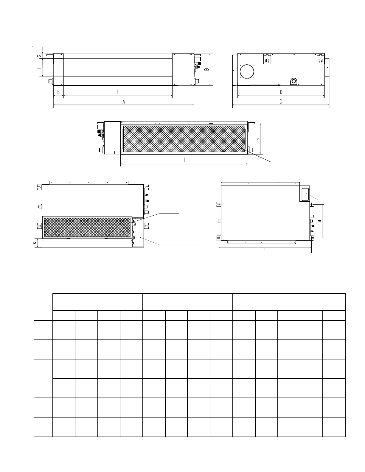
Positioning the ceiling hole, indoor unit and hanging screw bolts.
See table below for dimensions.
Air
filter
Electric
control
cabinet
Air
filter
Electric
control cabinet
Figure 8
ABCDE FGH I JKLM
12
27 1/2"
700mm
8"
210mm
25"
635mm
22 1/4"
570mm
2 1/2"
65mm
19 1/4"
493mm
1 1/4"
35mm
4 3/4"
119mm
23 1/4"
595mm
8"
200mm
3"
80mm
29"
740mm
13 3/4"
350mm
12, 18
36"
920mm
8"
210mm
25"
635mm
22 1/4"
570mm
2 1/2"
65mm
28"
713mm
1 1/4"
35mm
4 3/4"
119mm
32"
815mm
8"
200mm
3"
80mm
37 3/4"
960mm
13 3/4"
350mm
45"
1140mm
8"
210mm
25"
635mm
22 1/4"
570mm
2 1/2"
65mm
36 3/4"
933mm
1 1/4"
35mm
4 3/4"
119mm
40 3/4"
1035mm
8"
200mm
3"
80mm
46 1/2"
1180mm
13 3/4"
350mm
36"
920mm
10 1/2"
270mm
25"
635mm
22 1/4"
570mm
2 1/2"
65mm
28"
713mm
1 1/4"
35mm
7"
179mm
32"
815mm
10"
260mm
3/4"
20mm
37 3/4"
960mm
13 3/4"
350mm
30-36
45"
1140mm
10 1/2"
270mm
30 1/2"
775mm
28"
710mm
2 1/2"
65mm
36 3/4"
933mm
1 1/4"
35mm
7"
179mm
40 3/4"
1035mm
10"
260mm
3/4"
20mm
46 1/2"
1180mm
19 1/4"
490mm
42-60
47"
1200mm
11 3/4"
300mm
34"
865mm
31 1/2"
800mm
31"
80mm
38"
968mm
1 1/2"
40mm
8"
204mm
43"
1094mm
11 1/4"
288mm
1 3/4"
45mm
48 3/4"
1240mm
19 3/4"
500mm
Size of
mounted lug
24
Outline dimemsion
Air outlet
opening size
Air return
opening size
6
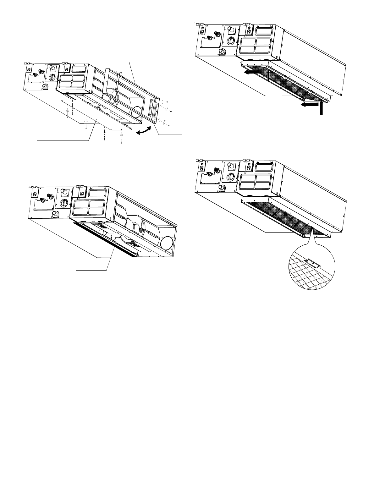
Adjusting the airflow direction
1. Remove the ventilation panel and flange; cut off the
staples at the side rail.
Air return flange
Ventilation panel
Side rail
Figure 9
2. Attach the seal sponge as shown below. Change the
mounting positions of the air return panel and air return
flange.
Seal sponge
Figure 10
3. When installing the filter mesh, place the filter mesh in
the flange and push up to set it in place, as shown by
the arrows in the following Figure 11.
Figure 11
4. Insert the clips in the flange holes as shown in Figure
12.
Figure 12
7
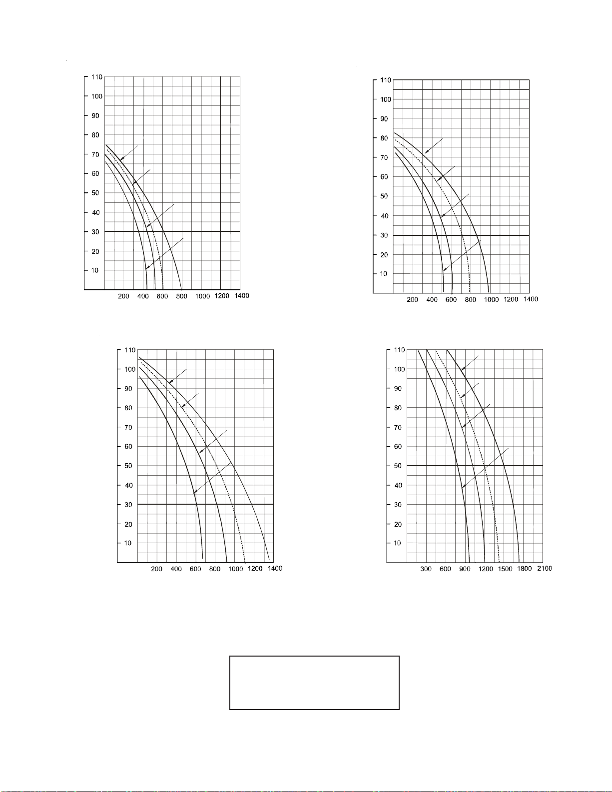
Fan Performance - Stactic Pressure Curve
Model 12
E
x
t
e
r
n
a
l
S
t
a
t
i
c
P
r
e
s
s
u
r
e
(
P
a
)
Super High Speed
High Speed (reserved)
Low Speed
Medium Speed
(Pa)
Air volume (m
3
/h)
Low Speed
Medium Speed
High Speed (reserved)
Super High Speed
Model 18
(Pa)
Air volume (m
3
/h)
E
x
t
e
r
n
a
l
S
t
a
t
i
c
P
r
e
s
s
u
r
e
(
P
a
)
Model 24
Low Speed
Medium Speed
High Speed (reserved)
Super High Speed
(Pa)
Air volume (m
3
/h)
High Speed (reserved)
Super High Speed
Model 30
(Pa)
Low Speed
Medium Speed
Air volume (m
3
/h)
NOTE:
1 m
3
/hr = 0.586 CFM
100 Pa = 0.4015 Inches of water
8
E
x
t
e
r
n
a
l
S
t
a
t
i
c
P
r
e
s
s
u
r
e
(
P
a
)
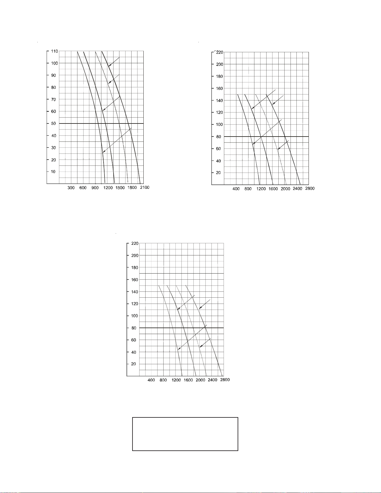
Model 36
(Pa)
Low SpeedLow Speed
Medium Speed
High Speed (reserved)
Super High Speed
Air volume (m
3
/h)
E
x
t
e
r
n
a
l
S
t
a
t
i
c
P
r
e
s
s
u
r
e
(
P
a
)
Super High Speed
High Speed (reserved)
Low Speed
Medium Speed
Model 42-48
(Pa)
Air volume (m
3
/h)
Model 60
(Pa)
E
x
t
e
r
n
a
l
S
t
a
t
i
c
P
r
e
s
s
u
r
e
(
P
a
)
Super High Speed
High Speed (reserved)
Low Speed
Medium Speed
Air volume (m
3
/h)
Fan Performance - Static Pressure Curve
NOTE:
1 m
3
/hr = 0.586 CFM
100 Pa = 0.4015 Inches of water
9
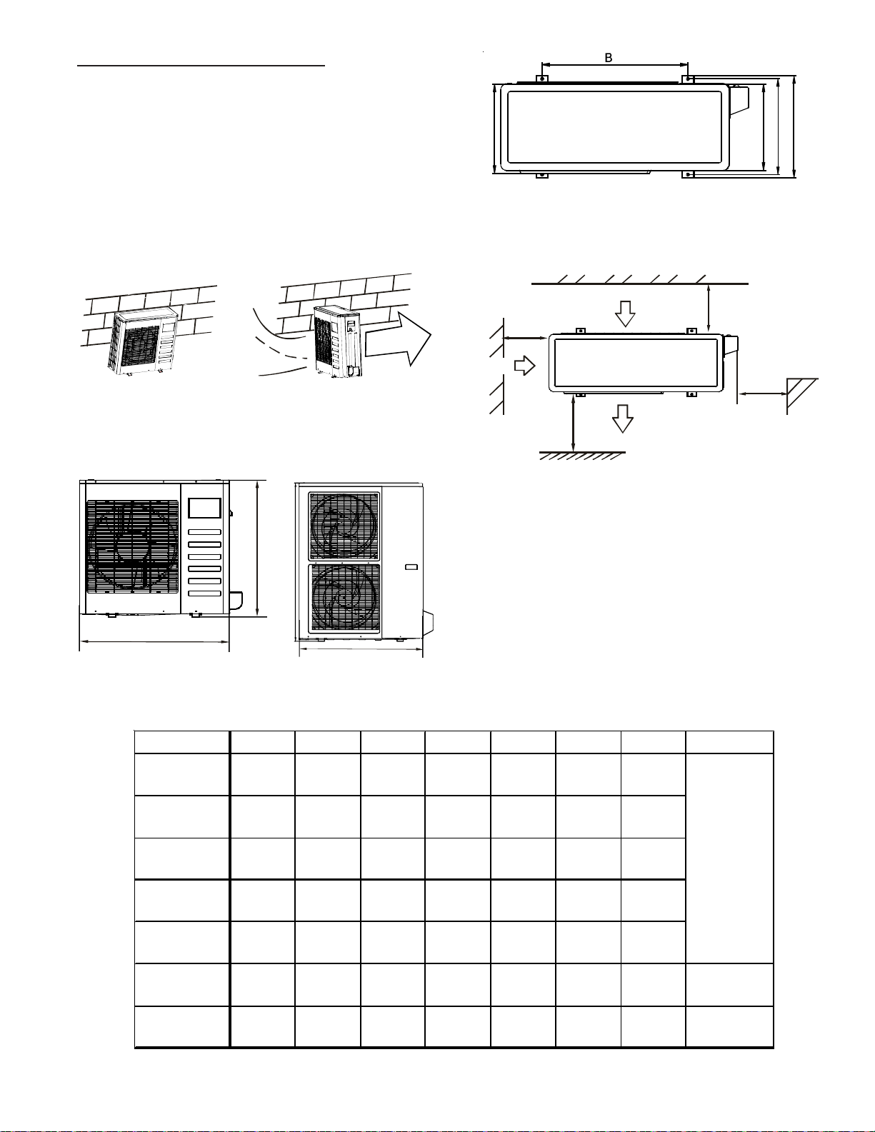
OUTDOOR UNIT INSTALLATION
The following are considerations before installing the out-
door unit.
• Install the outdoor unit on a rigid base to prevent noise
and vibration.
• Place the outdoor unit in such a manner to minimize
restriction of discharge air.
• Protect the unit from prevailing winds. To ensure the
unit operates correctly, place the unit lengthwise along
a wall or use a dust or shield plate.
Figure 13A
Figure 13B
S
T
R
O
N
G
W
I
N
D
• Install in a place where the unit is easily accessible
for installation and maintenance.
A
A
H
Figure 14A Figure 14B
C
E
D
F
Figure 14C
• See Figure 15 for minimum distances to obstacles.
Two of the three must remain unobstructed.
M
P
N
Air Inlet
Wall or obstacle
Air Outlet
Air Inlet
>12”
(30cm)
>
1
2
”
(
3
0
c
m
)
>24”
(60cm)
>
7
9
”
(
2
0
0
c
m
)
Figure 15
Moving and Installation
Notes:
• The inlet of the unit should not be used as a “handle”
when moving the unit.
• Use caution when moving the unit with a sling, since
the center of gravity is not in the unit’s physical cen-
ter.
• The fan should not be touched with hands or any for-
eign objects.
• Do not lean the unit more than 45° or lay it on its side.
ModelABC DEFHFigure Ref.
12,000
R-22 & R-410A
31"
780mm
21 1/2"
548mm
10 1/2"
266mm
11 1/2"
300mm
9 1/2"
241mm
9 1/2"
250mm
21 1/2"
547mm
18,000
R-22 & R-410A
30"
762mm
21"
530mm
11"
290mm
12"
315mm
10 1/2"
270mm
11"
282mm
23"
593mm
24,000
R-22 & R-410A
33"
842mm
22"
560mm
13"
335mm
14"
360mm
12"
312mm
12 1/2"
324mm
27"
695mm
30,000/36,000
R-22 & R-410A
39"
990mm
24 1/5"
624mm
14"
366mm
15 1/2"
396mm
13"
340mm
13 3/4"
354mm
38"
966mm
48,000
R-22 Only
39"
990mm
24 1/5"
624mm
14"
366mm
15 1/2"
396mm
13"
340mm
13 3/4"
354mm
38"
966mm
48,000
R-410A Only
35"
900mm
23"
590mm
14 3/4"
378mm
15 1/2"
400mm
13"
330mm
13 1/4"
340mm
45 3/4"
1167m m
Figure 14B
60,000
R-22 & R-410A
35"
900mm
23"
590mm
14 3/4"
378mm
15 1/2"
400mm
13"
330mm
13 1/4"
340mm
45 3/4"
1167m m
Figure 14B
Figure 14A
 Loading...