

Page 1
INSTALLATION
INSTRUCTIONS
Decomat 8666Installation instructions
9908
Decomat
8666
Serial no. 81511-
4996859-04
0301
1
Produced: 1999
Page 2

Contents
Installation instructionsDecomat 8666
Safety rules________________________________________________3
General safety rules _______________________________________ 3
Power cut-off device ______________________________________ 3
Caution symbols _________________________________________ 3
Installation ________________________________________________ 4
Wall-mounted model ______________________________________ 5
Electric connections ______________________________________ 6
Connection of water, steam, drain and dryer ____________________ 7
Functional check _________________________________________ 9
Technical data_____________________________________________10
Electric circuit diagram _____________________________________11
9908
2
Page 3
Safety rules
This machine is designed with a number of integrated safety devices. To avoid
personal injury it is essential that the safety devices are not bypassed or in any
other way put out of action.
General safety rules
• The machine should be connected according to the instructions.
• The machine may not by used by juveniles.
• Installation work and servicing should be carried out by staff trained to use this
machine.
• The door switch on the machine may not be bypassed under any circumstances.
• Leakage in the system, eg, due to worn lid gasket, must be repaired immediately.
• Personnel concerned must study valid handbooks and service manuals prior to
any repairs or service work.
• All plug-in leads must be unplugged from all of the circuit boards of the control
system before any welding on or close to the dishwasher is started.
• The machine may not be sprayed with water.
• Caution must be observed when using corrosive detergents.
• Safety precautions must be observed when using hot water or steam.
Decomat 8666Installation instructions
Power cut-off device
The machine can be provided with a separate main switch in the power supply line,
easily accessible on the wall.
Caution symbols
This manual contains certain warnings, instructions and advice of such importance
that they are particularly emphasized. The configuration and use of the
appertaining symbols are as follows:
This symbol indicates a warning in the text. It gives warning of
dangers which could lead to minor or major injury to the person
and even to a fatality.
It is also used in warnings to avoid damage to the machine.
9908
3
Page 4
Installation
Installation instructionsDecomat 8666
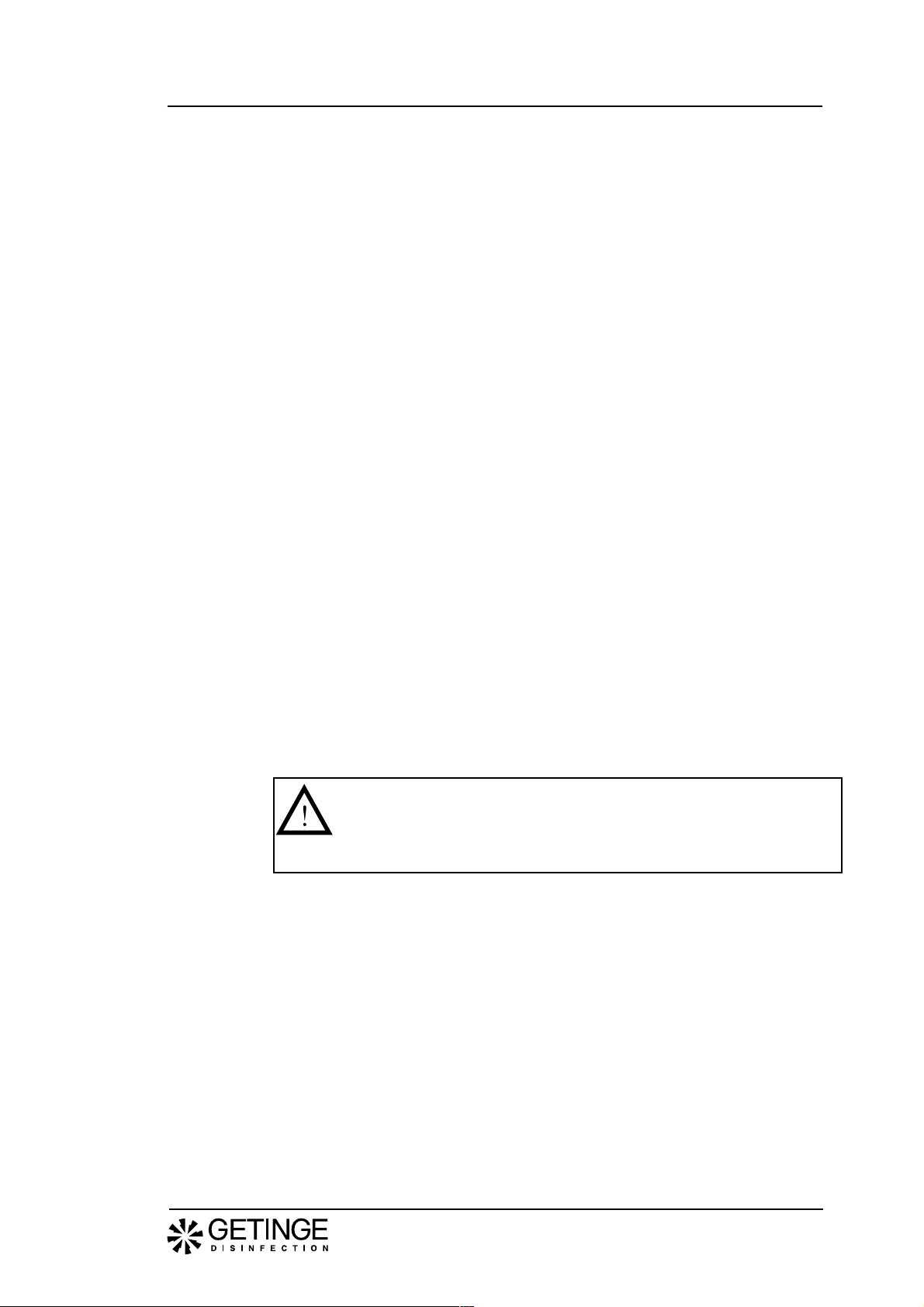
• Pull the machine (standing on a transport pallet) to where it is to stand.
• Lift the machine from the transport pallet.
• Place the machine in position and set the adjusting screws of the feet to make
the machine stand firm and level. Check with a spirit level as shown in figure 1
to ensure that the machine is level.
• The floor on which the machine is to stand must be horizontal and smooth.
Fig. 1. Adjusting
9908
V769
If the machine is to be moved using a fork-lift truck:
• Position the forks of the truck as illustrated in figure 2 so as not to damage the
machine.
Fig. 2. Positioning the fork-lift forks.
Bottom frame
V318
4
Page 5
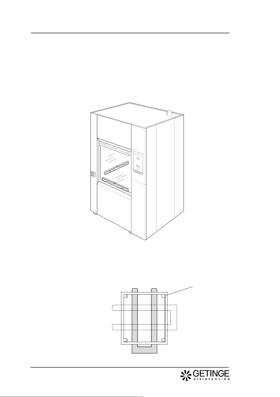
Wall-mounted model
• If the machine is fitted with two doors and is to be installed in a wall, the
clearance between wall and machine must be at least 25 mm.
• If several machines are mounted in-line, they must be adjusted to the same
height when being installed (especially important when a loading trolley is
used)
• If a plinth plate is used, the height from the floor to the bottom of the machine
must be at least 100 mm.
• Set the adjusting screws on the feet to make the machine stand firm and level.
Check with a spirit level on the sides of the machine.
• The floor in front of all the machines must be level and smooth to ensure that
the loading trolley works satisfactorily.
Decomat 8666Installation instructions
800
50
Clena side Soiled side
1870
1895
>100
V398
V768
9908
Fig. 3. Installed in wall
5
Page 6
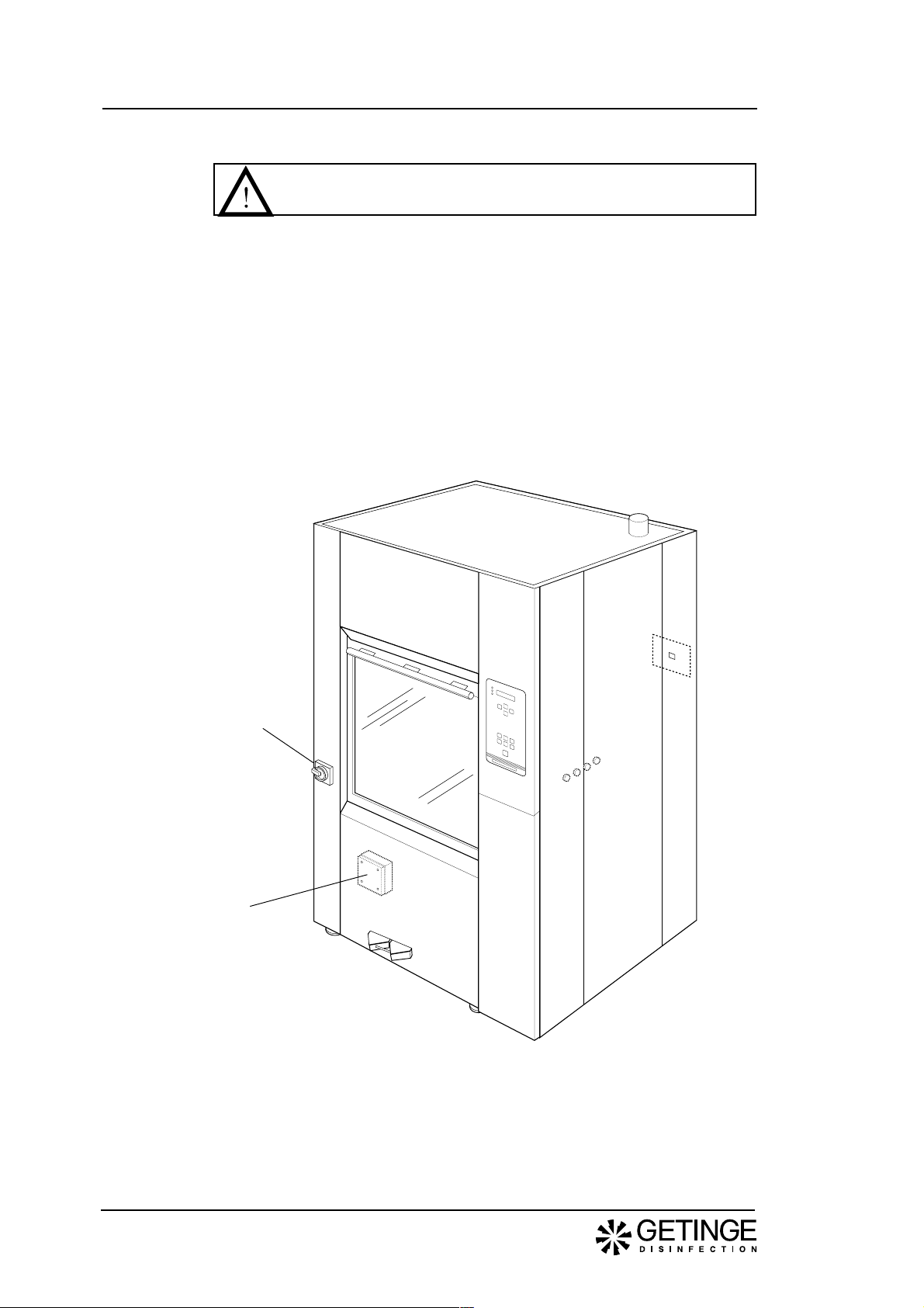
Electric connections
Installation may be made by authorized personnel only.
• The machine can be provided with a separate main switch, with a 3 mm gap, in
the power supply line to facilitate maintenance and service.
• Position the disconnecting switch easily accessible on the wall.
Electrical connections on the main switch located on the front of the machine are
made as follows:
• The disinfector is connected to protective earth and to the supply voltage
indicated on the data plate.
• Ensure that the correct size of fuse is fitted. The fuse value is stated on the
data plate.
Installation instructionsDecomat 8666
Main switch
Electrical
connection
V770
Fig. 4. Electrical connection (see electric circuit diagram in the service
instructions)
9908
6
Page 7

Connection of water, steam, drain and dryer
• Fit the connections for water, and steam if used, with separate shut-off cocks.
Flush the water and any steam pipes that are to be connected to the machine
so that they are clean and thus prevent clogging of filters and valves.
• Connect the disinfector to the cold and hot water supply, and to steam and
condensate connections if relevant. The connections must be in compliance
with the following requirements:
Connection Pressure Consumption
Cold water 3/4” (20 mm) 100-800 kPa ≥33 litres per phase
Hot water 3/4” (20 mm) 100-800 kPa ≥33 litres per phase
Distilled water/Deionized water 3/4" (20 mm) 100-800 kPa* ≥33 litres per phase
Steam 1/2” (15 mm) 300-450 kPa 0.65 kg/min (300 kPa)
Condensate 1/2" (15mm)
Compressed air 1/2” (15 mm)
* A separate supply pump must be used if pressure is below 50 kPa.
Note
Distilled or deionized water must have conductivity that is lower
than 40 µS/cm.
Decomat 8666Installation instructions
Fig. 5. Connection of water, steam, drain and dryer
1. Distilled/ deionized water
350 mm above floor level
2. Hot water 350 mm above floor level
3. Cold water 350 mm above floor level
4. Electric connection 350 mm above floor level
9908
No cables or pipes
allowed in this area
No cables or pipes
allowed in this area
Adjustable within
this zone
5. Drain connection at floor level
6. Steam connection 350 mm above floor level
7. Condense connection 350 mm above floor level
8. Dryer evacuation in machine top
9. Compressed air connection (Loader/Unloader)
400mm above floor level
7
Page 8

Installation instructionsDecomat 8666
• Teflon tape is recommended for the sealing of connections.
• Connect the disinfector to a drain that has a capacity of at least 30 litres per
minute. The drain may be connected to the rear or downwards as indicated in
figure 6. Diameter of drain: 50 mm.
V413
50 mm
V768
Fig. 6. Connection for dryer
• Connect evacuation from the dryer (ie, if machine is equipped with dryer). Air
flow rate: approx. 225 m3/h.
9908
8
Page 9

Functional check
• Ensure that the machine is connected to the correct power supply and that the
drain, water, steam and condensate connections are correctly made. Open the
water and steam cocks.
• Fill the detergent and rinsing agent bottles and place their level alarms in the
bottles.
• When starting up a new machine, the door must be opened as follows:
start-button twice.
Machines with double doors have a locking system whereby only one door can
be opened at a time.
If the door on the soiled side will not open, check that the door on the clean side
is closed and locked. If not, proceed as follows: For manually operated door:
Close the door and depress button ”DOOR”.
Automatic door: Depress button ”DOOR”.
• Place a basket in the washing chamber and close the door.
• Choose a program in which dosing is made from each of the detergent and rinseaid bottles and start the machine (see Operating Instructions).
• Ensure that filling with water in the machine is satisfactory.
Decomat 8666Installation instructions
Set the main switch to 1 and select program 1. Then press the
For manually operated doors - Press the handle down.
For automatic doors - Door opening is automatic.
9908
Note.
The circulation pump must be filled with water. The axial seal may
be damaged if there is no water in the pump.
• Ensure that the circulation pump is rotating in the right direction as indicated by
the arrow on the pump motor. If not, break the power supply, change the phase
sequense and restart the machine.
V766
Fig 9. Circulation pump
• Ensure that the dispenser pumps operate at the correct time in accordance with
the description of the program in the Operating Instructions and that detergent is
supplied.
• Check while the program is running that the door/doors cannot be opened.
• On machines with manually-operated double doors, check the door locking
function on completion of a program as follows:
- Ensure that the door on the soiled side cannot be opened.
- Open the door on the clean side and then close it again.
- Push the DOOR button.
- Open the door on the soiled side.
- Check that the door on the clean side cannot be opened.
• Ensure that there is no leakage of water or steam. Re-tighten connections for
water, steam and drainage if required.
9
Page 10

T echnical data
Weight, incl. water 3 5 0 kg
Width 1110 mm
Depth 910 mm
Height 1870 mm
Consumption of water 3 3 l/phase
Environmental requirements:
Cold water
Hot water
Dest./deionized water
Condensate 15 (1/2") mm
Steam
Exhaust air
Electric power
Compressed air connection 4-8 bar
Max. ambient temperature 5 0 °C
Noise level 6 0 dB (A)
9908
Installation instructionsDecomat 8666
Humidity, maximum 80% at 31 ° C
Room temperature 5 - 40 ° C
Connections 20 (3/4") mm
Pressure 100-800 kPa
Rate of flow 3 0 l/min
Temperature 45-60 °C
Connections 20 (3/4") mm
Pressure 100-800 kPa
Rate of flow 3 0 l/min
Connections 20 (3/4") mm
Pressure 100-800 kPa (a separate supply pump must
be fitted if pressure is less than 50 kPa
Rate of flow 3 0 l/min
Connections 15 (1/2") mm
Pressure 300-500 kPa
Consumption 0,65 kg/min by 300 kPa
Drain dia. 50 (2") m m
Capacity 50 1/min
Flow rate approx. 225 m3/h
Variant G2 23 0 V, 3+PE, 50/60 Hz (TN)
Fuse 3x50 A
Rated power 17,5 kW
Variant G3 400 V, 3 N+PE, 50/60 Hz (TN)
Fuse 3x35 A
Rated power 20,5 kW
Variant V2 without dryer 2 30 V, 3+PE, 50/60Hz (TN)
Fuse 3x16 A
Rated power 2,5 k W
Variant V3 Without dryer 4 00 V, 3 N+PE, 50/60Hz (TN)
Fuse 3x16 A
Rated power 2,5 k W
Variant V2 with dryer 2 30 V, 3+PE, 50/60Hz (TN)
Fuse 3x20 A
Rated power 6,9 k W
Variant V3 with dryer 4 00 V, 3 N+PE, 50/60Hz (TN)
Fuse 3x16 A
Rated power 6,9 k W
)
10
Page 11

Decomat 8666Installation instructions
Electric circuit diagram
Drawing no Document class Document contents
D-5000137 Lay out Elbox
D-5000131 Circuit diagram Connection, main switch
D-5000132 Circuit diagram Connection, alt 200/208 V
D-5000133 Circuit diagram Connection, alt 230 V
D-5000134 Circuit diagram Connection, alt 400 V
9908
11
Page 12

Page 13

Page 14

Page 15

Page 16

Page 17

Installation instructionsDecomat 8666
9908
12
Page 18

This product is manufactured by:
GETINGE DISINFECTION AB, Ljungadalsgatan 11, Box 1505, 351 15 Växjö, Sweden
 Loading...