

Page 1

GETINGE 86-SERIES
INSTALLATION MANUAL
502606400
SEV0 725 001-
Page 2

<Doc_I NS><Doc _502606 400><Re l_A><La ng_GB>
Page 2 of 20
Contents
FOREWORD ____________________________________________3
SAFETY REGULATIONS _________________________________4
General safety regulations ___________________________________ 4
The machine must be assembled and installed: ________________ 4
When the work is complete, check that _______________________ 5
Product liability ____________________________________________ 5
Attention symbols __________________________________________ 5
INSTALLATION __________________________________________6
Wall-mounted model ________________________________________ 7
Connecting electric power ___________________________________ 8
Alternative connection arrangements _________________________ 9
Connecting water, steam, waste and dryer ____________________ 10
Function check ____________________________________________ 13
TECHNICAL DATA _______________________________________ 15
Water quality - washer disinfectors _______________________18
Page 3

FOREWORD
This user manual is intended for users of Getinge 86-series washer disinfectors.
The instruction manual describes the design and operation of the machine and the maintenance for which the user is responsible. The purpose of the information in the manual
is to ensure safe operation and optimum efciency.
Before using the machine for the rst time, users must have read this instruction manual
and familiarized themselves with the operation of the machine and its safety instructions.
To conform to EN ISO 15883, the items must be placed in the proper accessories,
recommended by Getinge Disinfection AB.
The customer is responsible for ensuring that an Installation Qualication, an Operating
Qualication and a Performance Qualication according to EN ISO 15883 are carried
out before the product goes into service.
The information in this manual describes the machine as dispatched from Getinge.
There may be differences due to customization.
The machine is accompanied by the following documentation:
• User manual
Read the user manual before using the machine.
• Installation manual (this book)
• Technical manual
• Spare parts list
Getinge reserves the right to change the specication and design without prior notice.
The information in this manual was up to date on the date of issue of the manual.
© Copyright
The content of this manual must not be copied, in
whole or in part, without the written consent of Getinge.
Page 3 of 20
<Doc_I NS><Doc _502606 400><Re l_A><La ng_GB>
Page 4

<Doc_I NS><Doc _502606 400><Re l_A><La ng_GB>
Page 4 of 20
SAFETY REGULATIONS
This machine has been designed with a number of built-in safety devices.
To avoid injury, it is highly important not to bypass or disable these safety devices.
If the equipment is used in a manner that was not specied by the manufacturer, the
safety equipment on the machine may not be fully effective.
Operators and maintenance personnel must undergo safety training for the machine.
All personnel who handle chemicals for washing and disinfection must understand the
washing process, possible health hazards and ways of detecting leaks of toxic chemicals.
Operators and maintenance personnel must undergo regular training in the operation and
maintenance of the equipment. There must be a documented list of personnel who have been
trained on the machine. Trained personal must be tested to verify the training programme.
The equipment must be used in accordance with the safety instructions below.
If in doubt, contact a representative of the reseller without delay.
Important
Take care when handling the chemical agents used in the machine.
•
Read the instructions on the pack or contact the manufacturer before using the ma-
•
chine for instructions about:
- what to do if the substance comes into contact with the eyes or skin or if vapors
are inhaled.
- storage of packs and sorting of empty packs for disposal.
The machine must be connected in accordance with the instructions given in the
•
installation manual.
The machine may only be used by adults.
•
Installation and servicing may only be done by personnel trained for this machine.
•
Never bypass door safety switches.
•
Leaks in the system caused by worn seals in the door, for example, must be re-
•
paired immediately.
Before doing any repair or servicing work, the personnel concerned must study the
•
relevant handbooks and service manuals.
Before any welding is done on or close to the machine, all cables connected to the
•
control system via connectors and sockets must be disconnected.
Before doing any servicing or maintenance work on the machine, isolate it from the
•
electric power supply and drain all tanks.
Do not wash down or hose down the machine with water.
•
Take care when using corrosive substances.
•
Observe safety measures for steam and hot water.
•
The electrical cabinet may only be opened by authorized and trained personnel.
•
Spare parts must be obtained only via Getinge EDC.
•
The machine must be assembled and installed:
by qualied personnel.
•
in accordance with current local regulations and rules.
•
Warning:
To avoid the risk of back injury, this equipment should be assembled and
installed by two people.
Page 5

When the work is complete, check that
all parts have been installed in accordance with the installation instructions
•
all screws have been properly tightened
•
there are no sharp edges on any parts that may come into contact with people
•
all hoses, pipes and connections are intact and free from defects
•
all the functions of the machine are working properly. Adjust if necessary.
•
Carry out an Installation Qualication, an Operating Qualication and a Performance
Qualication according to ISO 15883 before putting the machine into service.
Incorrect use may result in damage and injury.
Product liability
Any modication or incorrect use of the equipment without the approval of Getinge Disinfection AB invalidates Getinge Disinfection AB´s product liability.
This product was manufactured by:
GETINGE DISINFECTION AB
Ljungadalsgatan 11
Box 1505
351 15 Växjö
Sweden
Attention symbols
Some of the warnings, instructions and advice in this manual are so important that we
use the following special symbols to draw attention to them. The symbols and designs
used are:
This symbol indicates a warning in the text of the manual. It warns of a hazard
that may lead to more or less severe injury and in certain cases mortal danger. It also highlights warnings to avoid damage to equipment.
Page 5 of 20
<Doc_I NS><Doc _502606 400><Re l_A><La ng_GB>
Page 6
<Doc_I NS><Doc _502606 400><Re l_A><La ng_GB>
Page 6 of 20
INSTALLATION
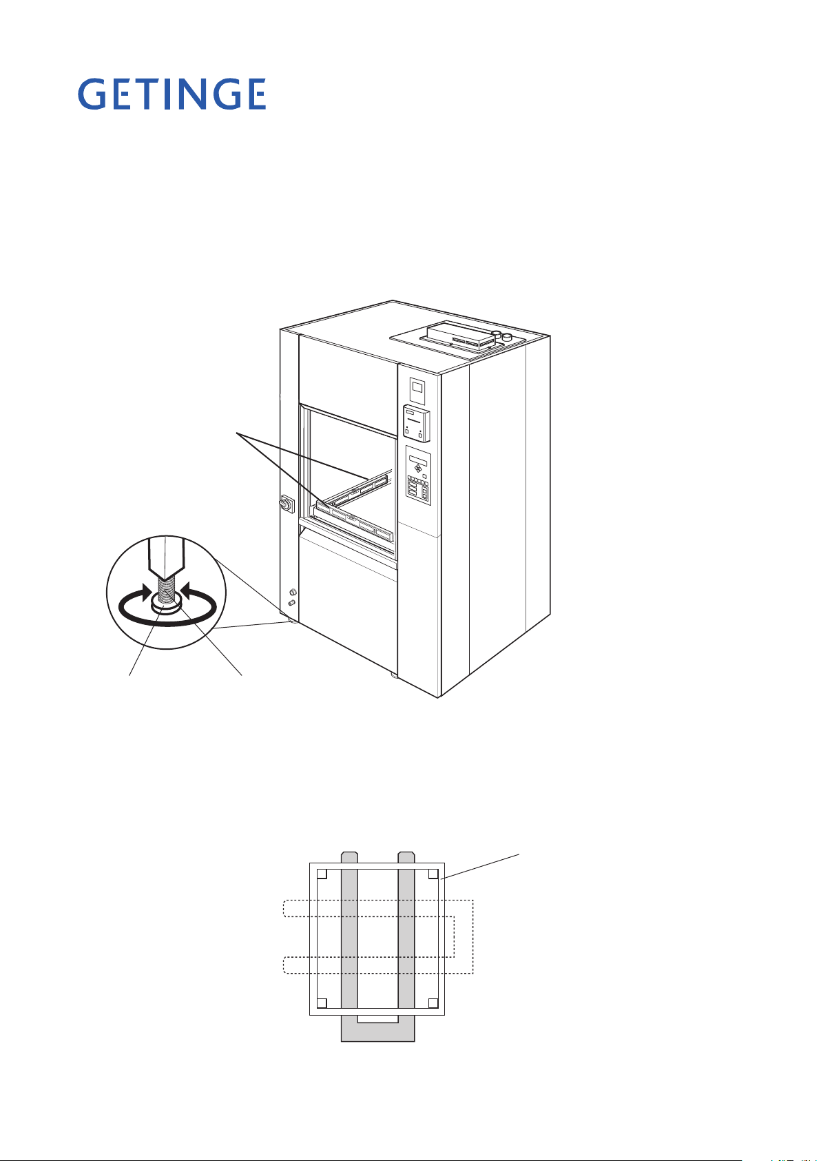
The oor where the machine is to stand must be at and level within ±5 mm.
•
Pull the machine (on a transport pallet) to the location where it will be installed.
•
Lift the machine off the pallet.
•
Position the machine at the chosen location and adjust the feet so that the machine
•
is stable.
Level the
machine with
a spirit level.
V1472
Adjusting screwFoot plate
Figure 1. Adjustment
Using a spirit level, check as shown in Figure 1 that the machine is level within ±2 mm.
•
If you need to move the machine by using a pallet truck:
position the pallet truck forks as shown in Figure 2 so as not to damage the machine.
•
Bottom frame
V318
Figure 2. Positioning the pallet truck forks.
Page 7

Wall-mounted model
If the machine has double doors and is to be mounted in a wall, the distance be-
•
tween machine and wall must be 15 mm.
If machines are to be installed next to each other they must be adjusted to the same
•
height on installation.
Where a plinth plate is used, the height from the oor to the underside of the ma-
•
chine must be at least 100 mm.
Set the machine horizontal with a spirit level on the side of the machine and adjust
•
with the feet.
For the loading trolley to work in all the machines, the oor in front of them must
•
be at and level.
Figure 3. Installation in a wall
Service area
V1475
Page 7 of 20
<Doc_I NS><Doc _502606 400><Re l_A><La ng_GB>
Page 8

<Doc_I NS><Doc _502606 400><Re l_A><La ng_GB>
Page 8 of 20
Connecting electric power
Installation may only be done by authorized personnel.
Connect electric power to the machine as follows:
Connect the power supply to the electrical connections of the machine; see the dia-
•
gram with alternative connection arrangements.
For easier servicing and maintenance, the supply to the machine should be tted
•
with a lockable isolator with a 3 mm break gap. The isolator must be located in an
easily accessible position on the wall.
It is important that the connection has the correct overcurrent protection. The
correct fuse rating is stated on the type plate.
The main switch on the front of the machine is connected to protective ground (earth)
and to the supply voltage stated on the type plate.
Main switch
Electrical
connection
V1473
Type plate
Figure 4 Electrical connection (see alternative connection arrangements)
Page 9

Alternative connection arrangements
MAIN SWITCH
HUVUDBRYTARE
HAUPTSCHALTER
INTERRUPTEUR ELECTRIQUE
ELECTRICAL CONNECTION
EL-ANSLUTNING
ELEKTROANSCHLUSS
CONNEXION ELECTRIQUE
-Q01
JB01
L1 L1 L1-1 L1 T1 L1-2
L2 L2 L2-1 L2 T2 L2-2
L3 L3 L3-1 L3 T3 L3-2
N N N-1 N N
PE PE PE -1 PE PE
MAIN SWITCH
HUVUDBRYTARE
HAUPTSCHALTER
INTERRUPTEUR ELECTRIQUE
ELECTRICAL CONNECTION
EL-ANSLUTNING
ELEKTROANSCHLUSS
CONNEXION ELECTRIQUE
-Q01
JB01
L1 L1 L1-1 L1 T1 L1-2
L2 L2 L2-1 L2 T2 L2-2
L3 L3 L3-1 L3 T3 L3-2
PE PE PE -1 PE PE
Electrically heated 240/415V 3N+PE, 50Hz 21.1kW 31A FUSE 3x32A 240V 3+PE, 60Hz 21.3kW 54A FUSE 3x60A
230/400V 3N+PE, 50/60Hz 19.7kW 30A FUSE 3x32A 230V 3+PE, 50Hz 19.7kW 54A FUSE 3x63A
220/380V 3N+PE, 50/60Hz 17.9kW 29A FUSE 3x32A 208 3+PE, 60Hz 20.5kW 59A FUSE 3x60A
200V 3+PE, 50/60Hz 19.1kW 58A FUSE 3x63A
Steam-heated 240/415V 3N+PE, 50Hz 6.5kW 14A, FUSE 3x20A 240V 3+PE, 60Hz 6.5kW 23A, FUSE 3x25A
230/400V 3N+PE, 50/60Hz 6.5kW 14A, FUSE 3x20A 230V 3+PE, 50Hz 6.5kW 24A, FUSE 3x25A
220/380V 3N+PE, 50/60Hz 6.5kW 14A, FUSE 3x20A 208V 3+PE, 60Hz 6.5kW 26A, FUSE 3x30A
200V 3+PE, 50/60Hz 6.5kW 27A, FUSE 3x32A
Steam-heated 240/415V 3N+PE, 50Hz 11.4kW 18A, FUSE 3x20A 240V 3+PE, 60Hz 11.5kW 30A, FUSE 3x30A
with booster 230/400V 3N+PE, 50/60Hz 10.7kW 17A, FUSE 3x20A 230V 3+PE, 50Hz 10.7kW 29A, FUSE 3x32A
220/380V 3N+PE, 50/60Hz 9.8kW 16A, FUSE 3x20A 208V 3+PE, 60Hz 11.1kW 33A, FUSE 3x35A
200V 3+PE, 50/60Hz 10.4kW 32A, FUSE 3x32A
Steam-heated & 240/415V 3N+PE, 50Hz 11.4kW 18A, FUSE 3x20A 240V 3+PE, 60Hz 11.5kW 30A, FUSE 3x30A
electrically heated 230/400V 3N+PE, 50/60Hz 10.7kW 17A, FUSE 3x20A 230V 3+PE, 50Hz 10.7kW 29A, FUSE 3x32A
220/380V 3N+PE, 50/60Hz 9.8kW 16A, FUSE 3x20A 208V 3+PE, 60Hz 11.1kW 33A, FUSE 3x35A
200V 3+PE, 50/60Hz 10.4kW 32A, FUSE 3x32A
Steam-heated & 240/415V 3N+PE, 50Hz 21.1kW 31A, FUSE 3x32A 240V 3+PE, 60Hz 21.3kW 54A, FUSE 3x60A
electrically heated 230/400V 3N+PE, 50/60Hz 19.7kW 30A, FUSE 3x32A 230V 3+PE, 50Hz 19.7kW 52A, FUSE 3x63A
with booster 220/380V 3N+PE, 50/60Hz 17.9kW 29A, FUSE 3x32A 208V 3+PE, 60Hz 20.5kW 59A, FUSE 3x60A
200V 3+PE, 50/60Hz 19.1kW 58A, FUSE 3x63A
Page 9 of 20
<Doc_I NS><Doc _502606 400><Re l_A><La ng_GB>
Page 10

<Doc_I NS><Doc _502606 400><Re l_A><La ng_GB>
Page 1 0 of 20
Connecting water, steam, waste and dryer
Installation may only be done by authorized personnel.
Provide water and, if required, steam connections with separate stopcocks. Flush
•
out the water and steam pipes that are to be connected to the machine, to prevent
clogging of lters and valves.
Connect the disinfector to cold and hot water and to steam and condensate connec-
•
tions, if used. The connections must meet the following requirements:
Connection Pressure Flow rate
Cold water 3/4” (20 mm) male 100-800 kPa
Hot water 3/4” (20 mm) male 100-800 kPa
Dist. water/
de-ion. water
3/4” (20 mm) male 100-800 kPa*
Steam 1/2” (15 mm) female 300-500 kPa
Condensate 1/2” (15 mm) female
Compressed air 1/2” (15 mm) female 4 to 8 bar
* Where the pressure is lower than 100 kPa a separate feeder pump must be used.
** At chamber depth = 720 mm
*** At chamber depth = 800 mm
Note:
Distilled or de-ionized water must have a conductivity of less than 40 µS/cm.
approx 33 liters/phase**
approx 40 liters/phase***
approx 33 liters/phase**
approx 40 liters/phase***
approx 33 liters/phase***
approx 40 liters/phase***
0.9 to 1.0 kg/min
(300 kPa)
Page 11

Chamber depth 720 mm
Clean side
Soiled side
Chamber depth 800 mm
Clean side
Soiled side
Figure 5. Connecting water, steam, waste and dryer
1. Cold water 350 mm above the oor
2. Hot water 350 mm above the oor
3. Distilled/de-ionized water 350 mm above
the oor
4. Compressed air connection (in/out feeder)
400 mm above the oor
5. Steam connection 350 mm above the oor
6. Condensate connection 350 mm above
the oor
7. Drain connection at oor
8. Dryer exhaust air at roof
9. Electrical connection 350 mm above
the oor
A. No cables or pipes in this area
B. Adjustable within this range
Page 1 1 of 20
<Doc_I NS><Doc _502606 400><Re l_A><La ng_GB>
Page 12

<Doc_I NS><Doc _502606 400><Re l_A><La ng_GB>
Page 1 2 of 20
PTFE tape is recommended for sealing the connections.
•
Connect the disinfector to a waste outlet with a capacity of at least 50 litres/min.
•
Connect the waste as shown in Figure 5. Diameter of waste: 50 mm.
Figure 6. Connecting a dryer
Connect air exhaust from dryer (if the machine has a dryer).
•
Air quantity approx 350 m3/h.
V1474
Page 13

Function check
Check that the machine is connected to the correct voltage and the waste, water,
•
steam and condensate connections are correctly connected. Open the valves for
water and steam.
Fill the detergent containers and place alarm sensors in the containers.
•
When starting a new machine, the door can be unlocked and opened with U.
•
With a manually-operated door, the door must be pressed down with the handle
after it has been unlocked. An automatic door opens automatically.
Machines with double doors have a system of interlocks to ensure that only one
•
door can be opened at a time.
The clean-side door can only be opened if the completed process has been ap-
•
proved and the soiled-side door is closed and locked.
If the soiled-side door cannot be opened, check that the clean-side door is closed
•
and locked. If not, proceed as follows:
- Manually-operated door - Close the door and press W.
- Automatically-operated door - Press W.
Place a wash rack in the wash chamber and close the door.
•
Choose a program where dosing is done from all the detergent and rinse-aid con-
•
tainers and start the machine (see the instruction manual).
Check that the machine draws water.
•
Note:
On starting, there must be water in the circulation pump. If there is no water in the pump
the shaft seal may be damaged.
Check that the circulation pump is rotating in the right direction as indicated by the
•
arrow on the pump motor. If not, isolate the power, change the phase sequence at
the electrical connections and restart the machine.
V766
Figure 7. Circulation pump
Check that the dosing pumps work at the right time in accordance with the program
•
description in the instructions for use and that detergent is drawn off.
While the program is running, check that the door(s) cannot be opened.
•
Page 1 3 of 20
<Doc_I NS><Doc _502606 400><Re l_A><La ng_GB>
Page 14

<Doc_I NS><Doc _502606 400><Re l_A><La ng_GB>
Page 1 4 of 20
On a machine with manual double doors, check the door locking function when the
•
program is complete as follows:
- If the soiled-side door cannot be opened, check that the clean-side door is closed.
- Open and close the clean side door.
- Press W.
- Open the soiled-side door.
- Check that the clean side door cannot be opened.
Check that there are no water or steam leaks. If necessary, retighten water, steam
•
and waste connections.
Page 15

TECHNICAL DATA
Dimensions
Outside dimensions
Width 1110 mm
Depth
8666, CM303: 910 mm
8668, CM304: 990 mm
Height 1870 mm
Chamber, effective dimension
Chamber depth
8666, CM303 720 mm
8668, CM304 800 mm
Chamber width 665 mm
Chamber height 667 mm
Chamber volume
8666, CM303 300 litres
8668, CM304 340 litres
Weight including water and load.
Total 350-400Kg
Loading per machine foot 0.85 to 0.98 kN (four feet)
Specic area loading 3.4-3.9 kN/m
Floor area loading, machine foot 347 kN/m
2
2
Connections
Water consumption
8666, CM303 33 liters/phase
8668, CM304 40 liters/phase
Cold water
Recommended water quality: Drinking water with max 5°dH
Connection ISO G-3/4
Pressure 100-800 kPa
Flow rate 30 liters/min
Hot water
Recommended water quality: Preheated drinking water with max 5°dH
Temperature 45-60°C (113-140°F)
Connection ISO G-3/4
Pressure 100-800kPa
Flow rate 30 liters/min
Note 1.
The water consumption varies depending on the type of wash trolley and the items.
Note 2.
The water temperature affects the process time. The lower the water temperature, the longer
the process will take.
Note 1.
Note 1.
Note 2.
Page 1 5 of 20
<Doc_I NS><Doc _502606 400><Re l_A><La ng_GB>
Page 16

<Doc_I NS><Doc _502606 400><Re l_A><La ng_GB>
Page 1 6 of 20
Distilled/de-ionized water (option)
Recommended water quality: The maximum conductivity is determined by the desired
washing result.
Max temperature 60°C (140°F)
Note 2.
Connection ISO G-3/4
Pressure 100-800 kPa (where the pressure is lower than 100 kPa, a
separate pressure booster pump must be connected. This is
available as an option.)
Flow rate 30 liters/min
Compressed air (option with loader/unloader only)
Connection pressure 4.8 bar
Steam (only for a machine with steam-heated chamber)
Connection ISO G-1/2
Pressure 300-500kPa
Max steam temperature 160 °C (320 °F)
Consumption about 0.9-1.0 kg/min at 300 kPa
Notes 3, 4.
Steam condensate (only for a machine with steam-heated chamber)
Connection ISO G-1/2
Note 4.
Waste outlet
Dimension, out ø50 mm (2”)
Minimum capacity of receiving drain
1. Capacity 40 l/min, max 90 °C (194 °F)
2. Capacity with drain cooling (option) 80 l/min, max 60 °C (140 °F)
Recommended connection dimension 100mm
Evacuation air
Air quantity 350 m3/h approx.
Max temperature: 160 °C (320 °F)
Air humidity 60-100 %
Note 2.
The water temperature affects the process time. The lower the water temperature, the longer
the process will take.
Note 3.
The pressure and temperature of the steam affect the process time. The lower the pressure, the
longer the process will take.
Note 4.
The pressure differential between the supply and return lines must be greater than 100 kP.
Page 17

Other points
Circulation system
Design pressure: 200 kPa
Working pressure: max 130 kPa
Design temperature 160 °C (320 °F)
Working temperature 93°C (199°F)
Electrical connection
See the relevant connection option.
Environmental requirements
Air humidity max 80% at 31 °C (87 °F)
Room temperature 5-40 °C (41-104 °F )
Heat dissipation to the room
Max 4000 W hot air during drying.
Max 1100 W during disinfection at 90 °C (194 °F)
Max external temperature of the machine at 50 °C (123 °F)
Sound level
Table 1 below shows the sound power level as linear octave band values and as co-weighted,
A-weighted sound power level, both equivalent L wA and maximum LwAFmax.
Table 1
Calculated sound power level Lw for the test object, db ref 1 pW.
Octave band frequency (Hz) 125 250 500 1000 2000 4000 8000 LwA LwAFmax
Correction terms (Kok) 67 69 67 67 69 67 70 75 84
The calculated sound power level implies different sound levels LpA in different types of space.
With a larger room volume, the sound level decreases slightly and with a smaller room level it increases slightly. Table 2 below shows three example of what to expect in practice.
Table 2
Calculated sound level LpA for the test object in a 70m3 room, db ref 20 µPa.
Type of
room
Hard to
sound
Normallydamped
Damped Full-cover ceiling absorbent and some furnish-
Description Operator
position*
All surfaces of tile, plaster, concrete or similar,
ie no sound absorbing surfaces and no furniture
Some sound absorption in the form of furniture
and textiles.
ing with tables, chairs and textiles.
74 74
70 69
67 65
3 meters from
the machine
* The term “operator position” means 1 meter from the machine and 1.5 meters above the oor.
Degree of protection
IP21
Page 1 7 of 20
<Doc_I NS><Doc _502606 400><Re l_A><La ng_GB>
Page 18

<Doc_I NS><Doc _502606 400><Re l_A><La ng_GB>
Page 1 8 of 20
Water quality - washer disinfectors
The quality of the water used in all stages of cleaning is important for good results.
The water used in each stage must be compatible with:
* The material of which the washer disinfector is made
* The chemicals used in the process
* Process requirements for the various stages of the process
The main factors for good water quality are:
Hardness High hardness will cause limescale deposits in the washer disinfector, lead-
Ionic contaminants A high concentration of ionic contaminants may cause corrosion and pitting
Microbial contaminants The water used should not increase the biological load on the equipment
Sanitary chemicals High concentrations of and high exposure to sanitary chemicals may cause
ing to poor cleaning results.
on stainless steel. Heavy metals such as iron, manganese or copper cause
instruments to tarnish.
that is being treated against micro-organisms and their residual products
which may cause fever-like symptoms when they get into the human body.
corrosion and pitting on stainless steel.
Getinge Disinfection AB therefore recommends that water used in the pre-rinsing, washing and nal rinsing phases should be of drinkable quality in accordance with the guidelines. Detailed information about acceptable water quality can be found in “Guidelines
for Drinking Water Quality 3rd Edition” published by WHO.
Getinge Disinfection AB also recommends following local standards. RO (reverseosmosis) water (or similarly treated water) is used for the nal washing/disinfection
phase.
A typical specication for RO water is:
pH 5.5 to 8
Conductivity <30 µs.cm
-1
TDS <40 mg/l
Maximum hardness <50 mg/l
Chlorine <10 mg/l
Heavy metals <10 mg/l
Phosphates <0.2 mg/l som P2O
Silicates <0.2 mg/l som SiO
5
2
Endotoxins <0.25 EU/ml
Total number of micro-organisms <100 per 100 ml
Further advice should also be obtained from the manufacturers of chemical and medical
equipment.
Where local standards are stricter that Getinge Disinfection AB’s recommendations, they
should be followed. Note that it is the customer’s responsibility to supply the washer
disinfector with suitable water.
Page 19

Page 1 9 of 20
<Doc_I NS><Doc _502606 400><Re l_A><La ng_GB>
Page 20

Australia
Getinge Australia Pty Ltd
154 Lytton Road
Bulimba Qld 4171
info@getinge.com.au
Phone: +61-733 956 311
Belgium
Getinge NV
Nijverheidsstraat 2
BE-2160 Wommelgem
info@getinge.be
Phone: +32-33542865
Canada
Getinge Canada Ltd
1575 South Gateway Road,
Unit C
Mississauga Ontario
L4W 5J1
info@getingecastle.ca
Phone: +1-905 629 8777
China
Getinge (Suzhou) Co. Ltd
Rm. 720, 7/F, Century Financial Tower
No. 1,
Su Hua Road, Suzhou Industrial Park,
Suzhou,
Jiangsu Province
Phone: + (86512) 67621587,
67621589, 67611591
France
Getinge France SAS
BP 49, avenue du Canada
ZA de Courtaboeuf
Les Ulis, FR-91942
getinge.france@getinge.fr
Phone: +33-1 64 86 89 00
Germany
Getinge Van Dijk
Medizintechnik GmbH
Postfach 1125
Boekholter Weg 1B
DE-47628 Straelen
info@getingevandijk.de
Phone: +49-283 491 330
Italy
Getinge S.p.A.
Via dei Buonvisi 61/D
IT-00148 Roma
info@getinge.it
www.getinge.com/it
Phone: +39-06656631
Netherlands
Getinge B.V.
Fruiteniersstraat 27, Zwijndrecht
Postbus 1004
NL-3330 CA Zwijndrecht
info@getinge.nl
Phone: +31-78 610 24 33
South Africa
Getinge South Africa (Pty) Ltd
P O Box 48492
Hercules
Pretoria SA 0002
getinge@mweb.co.za
Phone: +27-123 721 370
Spain
Getinge Iberica SL
P.E. San Fernando, Avda. Castilla 2,
Edif. Francia 1era planta
San Fernando de Henares
Madrid ES-28830
administracion@getinge.es
www.getinge.com
Phone: + 34-916 78 26 26
Sweden
Getinge International AB
P O Box 69
SE-310 44 Getinge
info@getinge.com
Phone: +46-35 15 55 00
Switzerland
Getinge ALFA AG
Weidenweg 17
4310 Rheinfelden
info@alfa.ag
www.getingealfa.ch
Phone: +41-61 836 15 15
Getinge Shanghai Trading Co. Ltd
Unit C, 8/F, Luck Plaza,
300 Xuanhua Road, Shanghai
P.R. China
info@getinge.com.cn
www.getinge.com/cn
Phone: +86 21 5208 1122
Denmark
Getinge Danmark A/S
Firskovvej 23
DK-2800 Lyngby
getinge.danmark@getinge.com
www.getinge.dk
Phone: +45-45 93 27 27
Finland
Getinge Finland Ab
Hallonnäsgatan 23A,
FI-00210 Helsinki
getinge@getinge.fi
Phone: +358-968 241 20
Norway
Getinge Norge AS
Enebakk vn.117.
N-0680 Oslo
info@getinge.no
www.getinge.com/no
Phone: +47-23 03 52 00
Poland
Getinge Poland
Ul. Lirowa 27
02-387 Warszawa
office@getinge.pl
Phone: +48-22 882 06 26
Singapore
Getinge International Far East Pte.
Ltd.
20 Bendemeer Road,
#06-02, Cyberhub Building
Singapore, SG-339914
Phone: + 65 6396 7298
United Kingdom
Getinge UK Ltd
Orchard Way
Calladine Park
Sutton-In-Ashfield
Notts NG 17 1JU
sales@getinge.co.uk
Phone: +44-1623510033
USA
Getinge USA Inc.
1777 East Henrietta Road
Rochester, NY 14623-3133
info@getingeusa.com
www.getingeusa.com
Phone: +1-585 475 9040
www.getinge.com
 Loading...