

Page 1

Heavy-duty one-piece frame, designed for
added stability, requires no further
assembly.
Precision-balanced, rubber laminated,
cast-iron wheels, mounted on two
heavy-duty ball bearings.
Large, ribbed cast-iron table with heavyduty one-piece trunnion for 0 - 45° tilting,
for bevel cuts.
Convenient blade tension adjustment
hand wheel.
A tension scale allows the operator to
adjust the tension for different blade
widths.
Foot brake for quick blade stoppage after
machine shut-off.
4” dust collection port for easy hookup to
a dust collector.
Powerful totally enclosed fan cooled
(T.E.F.C.) industrial motor.
Magnetic safety switch with emergency
stop button for added safety.
Tri-Axis bearing guides.
WHEEL SIZE
18” (450 MM)
WHEEL SPEED
980 RPM - #90-270
1010 RPM - #90-270 HD
WIDTH OF WHEEL
1 1⁄8” (28.5 MM)
MIN/MAX BLADE WIDTH
1⁄4” TO 1” (6.3 TO 25.4 MM)
BLADE LENGTH
153” (3886 MM) - #90-270
168 1⁄2” (4280 MM) - #90-270 HD
BLADE SPEED
4460 FPM (1338 MPM) - #90-270
4700 FPM (1410 MPM) - #90-270 HD
MAXIMUM DEPTH OF CUT
12” (305 MM) - #90-270
18” (457 MM) - #90-270 HD
MAXIMUM WIDTH OF CUT
17 1⁄4” (438 MM)
TABLE SIZE
24” X 19 1⁄2” (610 X 500 MM)
TABLE TILT
0° TO 45° (OUT)
TABLE HEIGHT
35 1⁄2” (902 MM)
MOTOR
- #90-270
M1 - 3 HP, 220 V, 1 PH, 19 A
M2 - 3 HP, 220/440 V, 3 PH, 8/4.6 A
M3 - 3 HP, 600 V, 3 PH, 2.9 A
MOTOR
- #90-270HD
M1 - 5 HP, 220 V, 1 PH, 23 A
M2 - 5 HP, 220/440 V, 3 PH, 13.3/7.6 A
M3 - 5 HP, 600 V, 3 PH, 4.8 A
WEIGHT
616 LBS (280 KG) - #90-270
710 LBS (323 KG) - #90-270 HD
REVISION 1 - FEB 04/08
© COPYRIGHT GENERAL INTERNATIONAL 02/2008
Page 2

GENERAL® INTERNATIONAL
8360 Champ-d’Eau, Montreal (Quebec) Canada H1P 1Y3
Telephone (514) 326-1161 • Fax (514) 326-5555
www.general.ca
THANK YOU for choosing this General® International model 90-270 or 90-270HD
18”Wood Cutting Bandsaw. This machine has been carefully tested and inspected before shipment and if properly used and maintained, will provide you with years of reliable service. To
ensure optimum performance and trouble-free operation, and to get the most from your
investment, please take the time to read this manual before assembling, installing and operating the unit.
The manual’s purpose is to familiarize you with the safe operation, basic function, and features
of this wood cutting bandsaw as well as the set-up, maintenance and identification of its parts
and components. This manual is not intended as a substitute for formal woodworking instruction, nor to offer the user instruction in the craft of woodworking. If you are not sure about the
safety of performing a certain operation or procedure, do not proceed until you can confirm,
from knowledgeable and qualified sources, that it is safe to do so.
Once you’ve read through these instructions, keep this manual handy for future reference.
GENERAL ® INTERNATIONAL WARRANTY
All component parts of General® International machinery are carefully tested and inspected during all stages of
production, and each machine is thoroughly inspected upon completion of assembly. Because of our commitment to quality and customer satisfaction, General® International agrees to repair or replace, within a period of 24
months from date of purchase, any genuine part or parts which, upon examination, prove to be defective in workmanship or material. In order to obtain this warranty, all defective parts must be returned freight pre-paid to
General® International Mfg. Co., Ltd. Repairs attempted without our written authorization will void this warranty.
Disclaimer: The information and specifications in this manual pertain to
the unit as it was supplied from the factory at the time of printing.
Because we are committed to making constant improvements,
General® International reserves the right to make changes to components, par ts or features of this unit as deemed necessary, without prior
notice and without obligation to install any such changes on previously
delivered units. Reasonable care is taken at the factory to ensure that
the specifications and information in this manual corresponds with that
of the unit with which it was supplied. However, special orders and “after
factory” modifications may render some or all information in this manual inapplicable to your machine. Further, as several generations of this
bandsaw and several versions of this manual may be in circulation,
if you own an earlier or later version of this unit, this manual may not
depict your machine exactly. If you have any doubts or questions
contact your retailer or our support line with the model and serial
number of your unit for clarification.
Page 3

Rules for Safe Operation
To help ensure safe operation, please take a moment to learn the machine’s applications and limita-
ions, as well as potential hazards. General® International disclaims any real or implied warranty and
t
hold itself harmless for any injury that may result from the improper use of it’s equipment.
1. Do not operate the bandsaw when tired, distracted
or under the effects of drugs, alcohol or any medication that impairs reflexes or alertness.
2. The working area should be well lit, clean and free
f debris.
o
3. Keep children and visitors at a safe distance when
the sander is in operation; do not permit them to
operate the sander.
4. Childproof and tamper proof your shop and all
machinery with locks, master electrical switches
and switch keys, to prevent unauthorized or unsupervised use.
5. Stay alert! Give your work your undivided attention.
Even a momentary distraction can lead to serious
injury.
6. Fine particulate dust is a carcinogen that can be
hazardous to health. Work in a well-ventilated area
and whenever possible use a dust collector. Wear
face, eye, ear, respiratory and body protection
devices.
7. Do not wear loose clothing, gloves, bracelets,
necklaces or other jewelry while the bandsaw is in
operation.
15. Use suitable work piece support if the work piece
does not have a flat surface.
16. Hold material firmly against the table.
7. Do not work on long stock without adequate sup-
1
port on the out feed end of the table.
18. If using a power feeder, stop the feeder before stopping the bandsaw.
19. Do not push or force stock into the blade. The bandsaw will perform better and more safely when working at the rate for which it was designed.
20. Avoid working from awkward or off balance positions. Do not overreach and keep both feet on floor.
21. Keep guards in place and in working order. If a
guard must be removed for maintenance or cleaning be sure it is properly re-attached before using
the tool again.
22. Never leave the machine unattended while it is running or with the power on.
23. Use of parts and accessories NOT recommended
by
General® International may result in equip-
ment malfunction or risk of injury.
8. Be sure that adjusting wrenches, tools, drinks and
other clutter are removed from the machine and/or
the table surface before operating.
9. Keep hands well away from the blade and all moving parts. Use a brush, not hands, to clear
away chips and dust.
10. Adjust and position upper and lower blade guides
before starting to cut. Upper blade guide should be
adjusted to approximately 1/8” above the material
to be cut.
11. Adjust blade tension and tracking before starting to
cut.
12. Saw teeth must point down toward the table.
13. Be sure that the blade has gained full operating
speed before starting to cut.
14. Always use a clean, properly sharpened blade.
Dirty or dull blades are unsafe and can lead to
accidents.
24. Never stand on machinery. Serious injury could result if the tool is tipped over or if the cutting tool is
unintentionally contacted.
25. Always disconnect the machine from the power
source before servicing or changing accessories
such as blades, or before performing any maintenance or cleaning, or if the machine will be left unattended.
26. Make sure that the switch is in the “OFF” position
before plugging in the power cord.
27. Make sure the tool is properly grounded. If equipped with a 3 - prong plug it should be used with a
three-pole receptacle.Never remove the third prong.
28. Do not use this bandsaw for other than its intended
use. If used for other purposes,
General® Interna-
tional disclaims any real implied warranty and
holds itself harmless for any injury, which may result
from that use.
Page 4
EELLEECCTTRRIICCAALL RREEQQUUII RREE MMEENNTTSS
NOTE: VOLTAGE REQUIREMENTS AND AMPERAGE DRAW FOR M2 & M3 3-PHASE MOTORS MAY NOT BE FULLY
DESCRIBED IN THIS MANUAL. FOR COMPLETE ELECTRICAL REQUIREMENTS REFER TO THE MOTOR I.D. NAME PLATE ON
THE MACHINE. IF IN DOUBT CONSULT A LICENSED QUALIFIED ELECTRICIAN BEFORE PROCEEDING.
Before connecting the machine to the power source, verify that the voltage of your power supply corresponds with
the voltage specified on the I.D. nameplate located on the back of the machine. A power source with greater voltage than needed can result in serious injury to the user as well as damage to the machine. If in doubt, contact a
qualified electrician before connecting to the power source.
This tool is for indoor use only. Do not expose to rain or use in wet or damp locations.
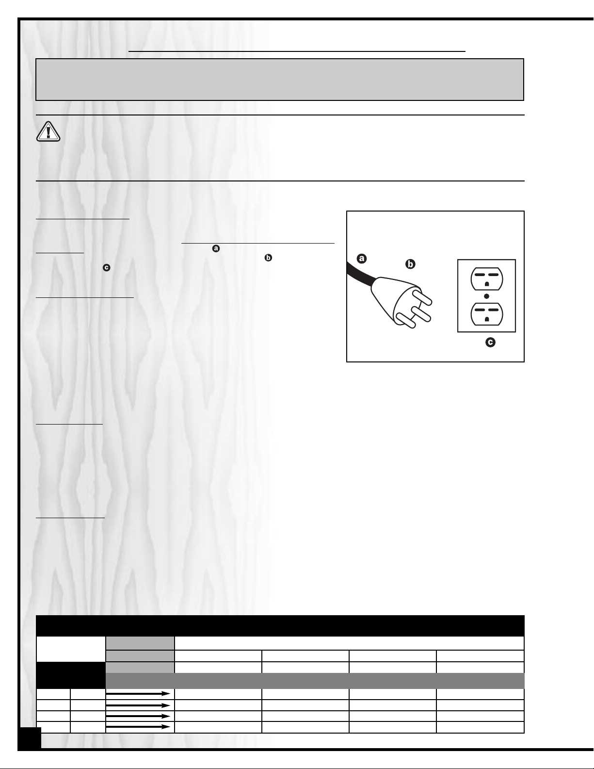
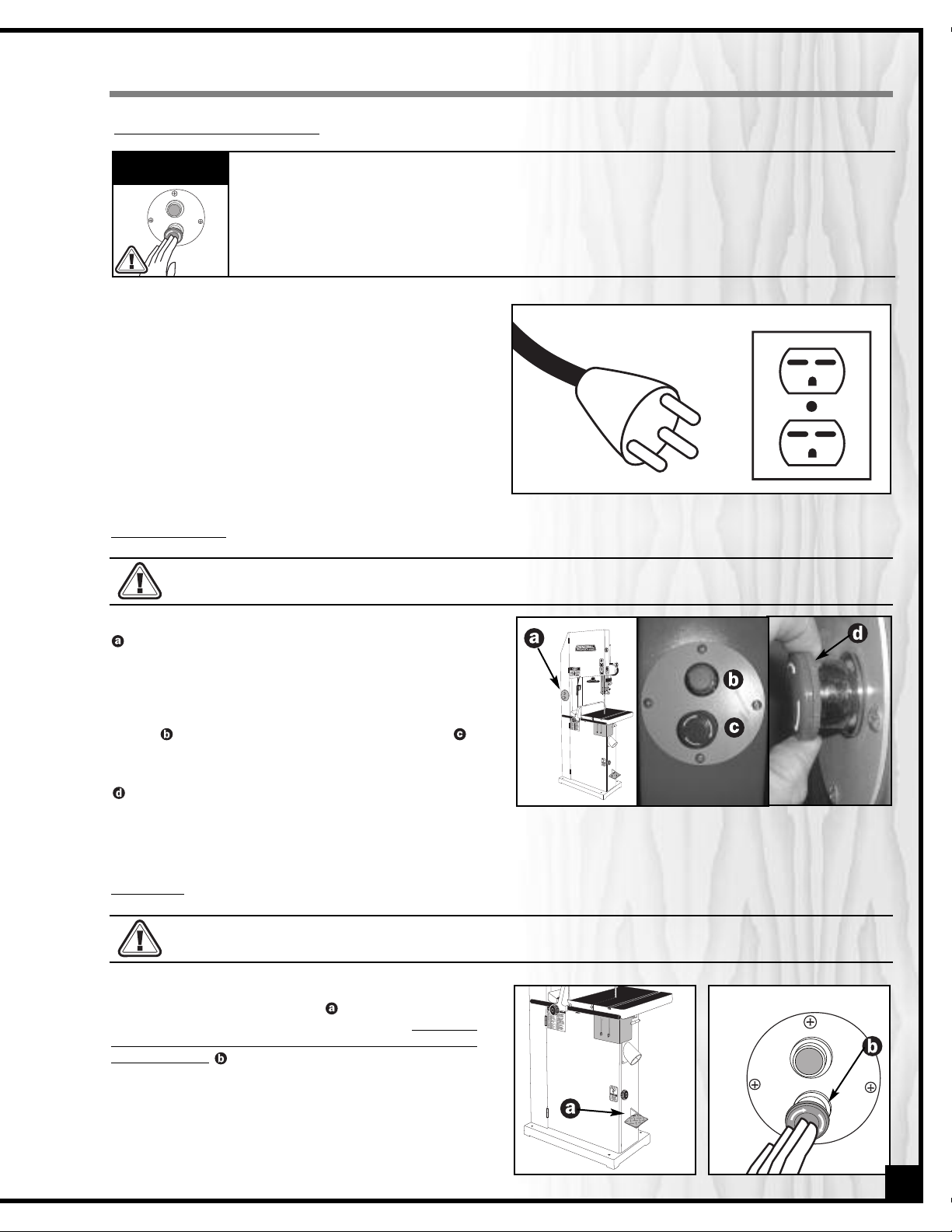
ELECTRICAL CONNECTIONS
Both a manual circuit breaker (or similar device) as well as an electrical plug are recommended and should be installed by a qualified
electrician. Use locally approved wire that includes a separate
grounding wire , and a 3 prong grounding type plug with a matching receptacle . (Fig. 1)
GROUNDING INSTRUCTIONS
In the event of an electrical malfunction or short circuit, grounding
reduces the risk of electric shock to the operator. The motor of the “M1”
model of this machine is wired for 220V single phase operation. As with
many stationary industrial type machines, because each installation
situation is unique, this bandsaw is supplied without a power cord or
plug. The installation of an appropriate power cord and plug must be
performed by a qualified electrician. The machine must be connected
to an electrical source using a power cord that has a grounding wire, which must also be properly connected to
the grounding prong on the plug. The outlet must be properly installed and grounded and all electrical connections must be made in accordance with all local codes and regulations.
Fig. 1
CIRCUIT CAPACITY
Make sure that the wires in your circuit are capable of handling the amperage draw from your machine, as well as
any other machines that could be operating on the same circuit. If you are unsure, consult a qualified electrician.
If the circuit breaker trips or the fuse blows regularly, your machine may be operating on a circuit that is close to its
amperage draw capacity. However, if an unusual amperage draw does not exist and a power failure still occurs,
contact a qualified technician or our service department.
EXTENSION CORDS
The use of an extension cord is not generally recommended for 220V equipment. If you find it necessary, use only
3-wire extension cords that have 3-prong grounding plug and a matching 3-pole receptacle that accepts the
tool’s plug. Repair or replace a damaged extension cord or plug immediately.
If you find it necessary to use an extension cord with your machine make sure the cord rating is suitable for the
amperage listed on the motor I.D. plate. An undersized cord will cause a drop in line voltage resulting in loss of
power and overheating. The accompanying chart shows the correct size extension cord to be used based on cord
length and motor I.D. plate amp rating. If in doubt, use the next heavier gauge. The smaller the number, the heavier
the gauge.
TABLE - MINIMUM GAUGE FOR CORD
VOLTS
110 V
220 V
25 ft.
50 ft.
18
18
16
14
TOTAL LENGTH OF CORD IN FEET
50 ft.
100 ft.
AWG
16
16
16
12
100 ft.
200 ft.
16
14
14
-
150 ft.
300 ft.
14
12
12
-
4
AMPERE
RATING
MORE
THAN
0
6
10
12
NOT
MORE
THAN
6
10
12
16
Page 5
18” WOOD CUTTING BANDSAW
90-270 or 90-270HD
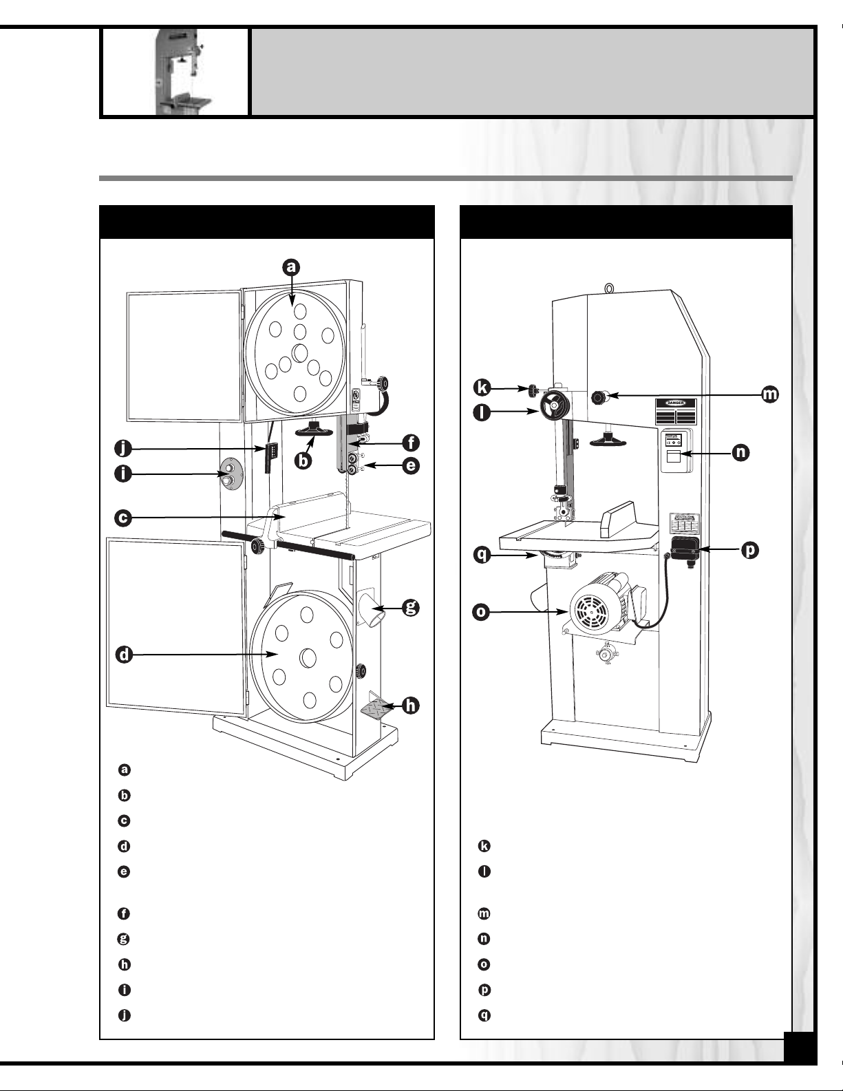
IDENTIFICATION OF MAIN PARTS AND COMPONENTS
FRONT VIEW
REAR VIEW
UPPER WHEEL
TENSION ADJUSTMENT HAND WHEEL
FENCE
LOWER WHEEL
UPPER BLADE GUIDES AND SUPPORT
BEARING ASSEMBLY
BLADE GUARD
DUST CHUTE
FOOT BRAKE PEDAL
ON/OFF SWITCH
BLADE TENSION INDICATOR
BLADE GUARD LOCK KNOB
BLADE GUARD ADJUSTMENT
HAND WHEEL
TRACKING ADJUSTMENT KNOB
SWITCH BOX
MOTOR
ELECTRICAL CONNECTION BOX
TABLE TILT ANGLE INDICATOR
5
Page 6
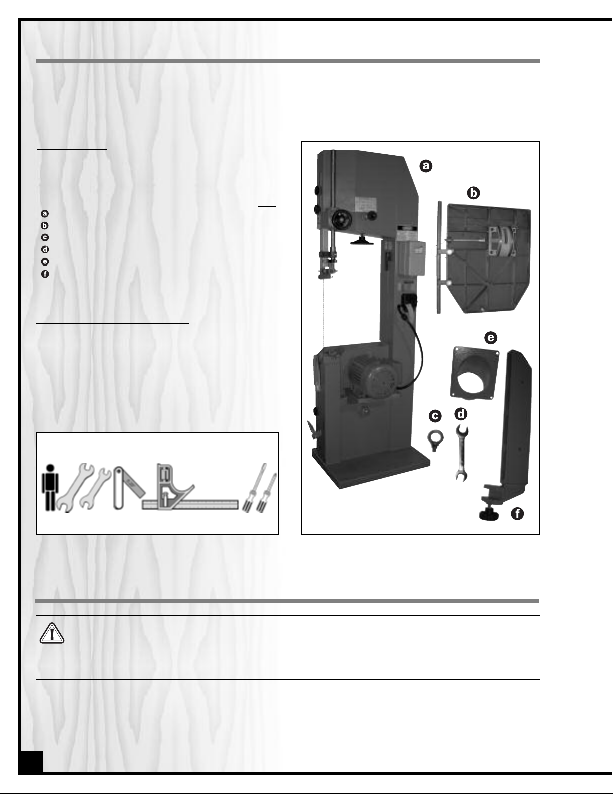
UNPACKING
Carefully unpack and remove the unit and its components from its shipping container and check for missing or
damaged items as per the list of contents below.
NOTE: Please report any damaged or missing items to your GENERAL® INTERNATIONAL distributor immediately.
IST OF CONTENTS
L
nce the parts have been removed from the packa-
O
ing, you should have the following items:
QTY
18” WOOD CUTTING BANDSAW 1
TABLE . . . . . . . . . . . . . . . . . . . . . . . . . . . . . . . . . . . . . .1
EYEBOLT . . . . . . . . . . . . . . . . . . . . . . . . . . . . . . . . . . . .1
19/21 MM COMBINATION WRENCH . . . . . . . . . . . . .1
DUST PORT . . . . . . . . . . . . . . . . . . . . . . . . . . . . . . . . . .1
RIP FENCE . . . . . . . . . . . . . . . . . . . . . . . . . . . . . . . . . . .1
ADDITIONAL REQUIREMENTS FOR SET UP
• Three extra people for help with lifting machine (or
hoist or forklift with chains)
• 14 mm open end wrench
• 12 mm open end wrench
• Feeler gauge set
• Combination square
• Flat head Screwdriver
• Phillips Screwdriver
3
LIFTING AND HANDLING THE MACHINE
These models 90-270 and 90-270HD 18” wood cutting bandsaws are very heavy. Do not over-exert. The help of at
least three assistants, a hoist or forklift with chains will be needed for the following step.
To limit the risk of serious injury or damage to the machine, any equipment used to lift this machine (hoist or forklift) should have a rated capacity in excess of 616 lbs (280 kg) for model 90-270 and of 671 lbs (305 kg) for model
90-270HD.
To limit the potential for damage in transport, this bandsaw is shipped from the factory in the horizontal position.
Because of its great weight a minimum of 3 extra people will be required to assist with lifting and setting the
machine upright. That being said, to limit the risk of serious injury or damage to the machine, ideally, a hoist should
be used. A hoisting eyebolt is provided for that purpose. Install the eyebolt on top of the bandsaw as instructed in
section “ASSEMBLY INSTRUCTIONS” on page 8.
6
Page 7
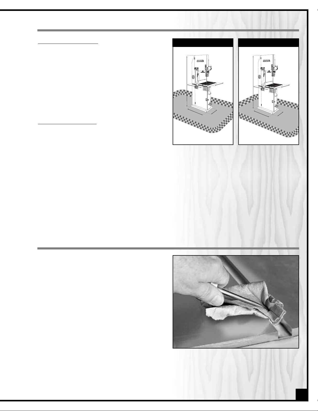
PLACEMENT WITHIN THE SHOP / ESTABLISHING A SAFETY ZONE
2
7
”
27”
1
5
”
15”
7
5
”
75”
2
5
”
25”
3
3
”33”
2
7
”
2
0
”
8
2
”
2
7
”
3
4
”
2
7
”
27”
2
0
”
20”
8
2
”
82”
2
7
”
27”
3
4
”
34”
PLACEMENT WITHIN THE SHOP
Model #90-270HDModel #90-270
This machine should be installed and operated only on
a solid, flat and stable floor that is able to support the
weight of the bandsaw 616 lbs (280 kg) for model 90-
70 and of 671 lbs (305 kg) for model 90-270HD and the
2
operator. Using the dimensions shown in Fig. 2 & 2.1 as
a guideline, plan for placement within your shop that
will allow the operator to work unencumbered and
unobstructed by foot traffic (either passing shop visitors
or other shop workers) or other tools or machinery.
ESTABLISHING A SAFETY ZONE
For shops with frequent visitors or multiple operators, it is
advisable to establish a Safety Zone around shop
Fig. 2
machinery. A clearly defined “no-go” zone on the floor
around each machine can help avoid accidents that could cause injury to either the operator or the shop visitor.
It is advisable to take a few moments to either paint (using non-slip paint) or using tape, define on the floor the limits or perimeter of each machines safety zone. Take steps to ensure that all operators and shop visitors are aware
that these areas are off limits whenever a machine is running for everyone but the individual operating the unit.
Fig. 2.1
CLEAN UP
The protective coating on the saw table prevents rust
from forming during shipping and storage. Remove it
by rubbing with a rag dipped in kerosene, mineral spirits or paint thinner. (Dispose of potentially flammable
solvent-soaked rags according to manufacturer’s safety recommendations.)
A putty knife, held flat to avoid scratching the surface,
may also be used to scrape off the coating followed
by clean-up with solvent. Avoid rubbing the saw’s
painted surfaces, as many solvent-based products will
remove paint.
To prevent rust, apply a light coating of paste wax or use
regular applications of any after-market surface protectant or rust inhibitor such as General International “Top
Saver” item #GC-010.
Tip: With a screw driver, push a solvent-saturated rag into the T-slot to remove the grease.
7
Page 8
ASSEMBLY INSTRUCTIONS
For your convenience this bandsaw is shipped from the factory partially assembled and requires only minimal
assembly and set up before being put into service.
Serious personal injury could occur if you connect the machine to the power source before you have completed
the installation and assembly steps. DO NOT connect the machine to the power source until instructed to do so.
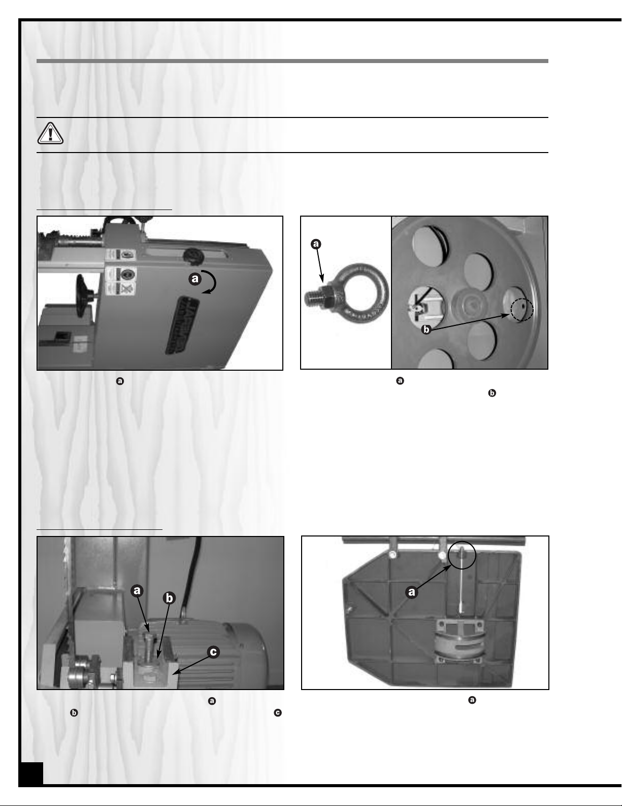
INSTALLING THE HOISTING EYEBOLT
1. Turn the knob clockwise to unlock the upper wheel
door, then open the door.
Put the nut back and tighten firmly, using the supplied 19 mm wrench, then close and lock the upper wheel door.
3.
2. Remove the nut from the provided hoisting eye-
bolt and insert the eyebolt in the hole located on
top of the bandsaw.
PREPARING TABLE INSTALLATION
1
. Remove the table tilt trunnion bolt and flat wash-
er , located on the trunnion support bracket
and set it aside.
8
2. Remove the table aligning pin from the table
slot on the front of the table.
Note: The table aligning pin should be easily removable with fingers only. If it is jammed, use pliers to remove it from the table slot.
Page 9
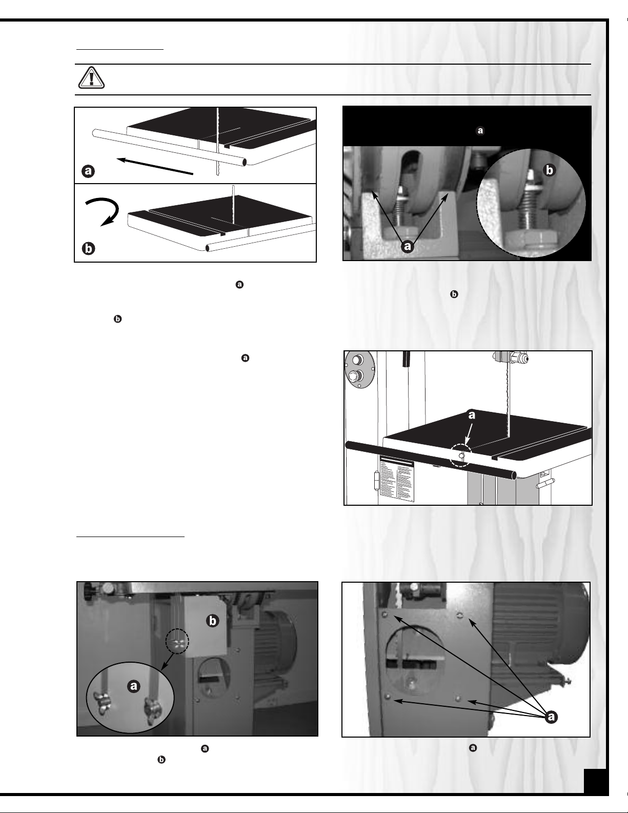
INSTALLING THE TABLE
This bandsaw table is heavy. Do not over-exert. The help of an assistant will be needed for the following step.
90° CW
Note: Make sure that both table tilt trunnion grooves
align in the trunnion bracket .
1. Guide the gap between the rail and the edge of
the table over the saw blade then rotate 90°
clockwise so the slot is parallel to the blade, and
guide the table so the blade is at the end of the
slot .
3. Re-install the table aligning pin in the hole on
the front of the table.
INSTALLING THE DUST PORT
The dust port has a 4" opening
let on the right side of the band saw as follows:
to accommodate connection to a dust collector (not included). Install the dust out-
2. Put the flat washer down on the table tilt trunnion
then slip the table tilt trunnion bolt through the hole in
the trunnion bracket and tighten with the 19/21 mm
combination wrench provided.
1. Unscrew both wing nuts then remove the yellow
blade guard . Set it aside, along with the two
wing nuts and two flat washers.
Remove the four screws already mounted on
2.
the side panel.
9
Page 10
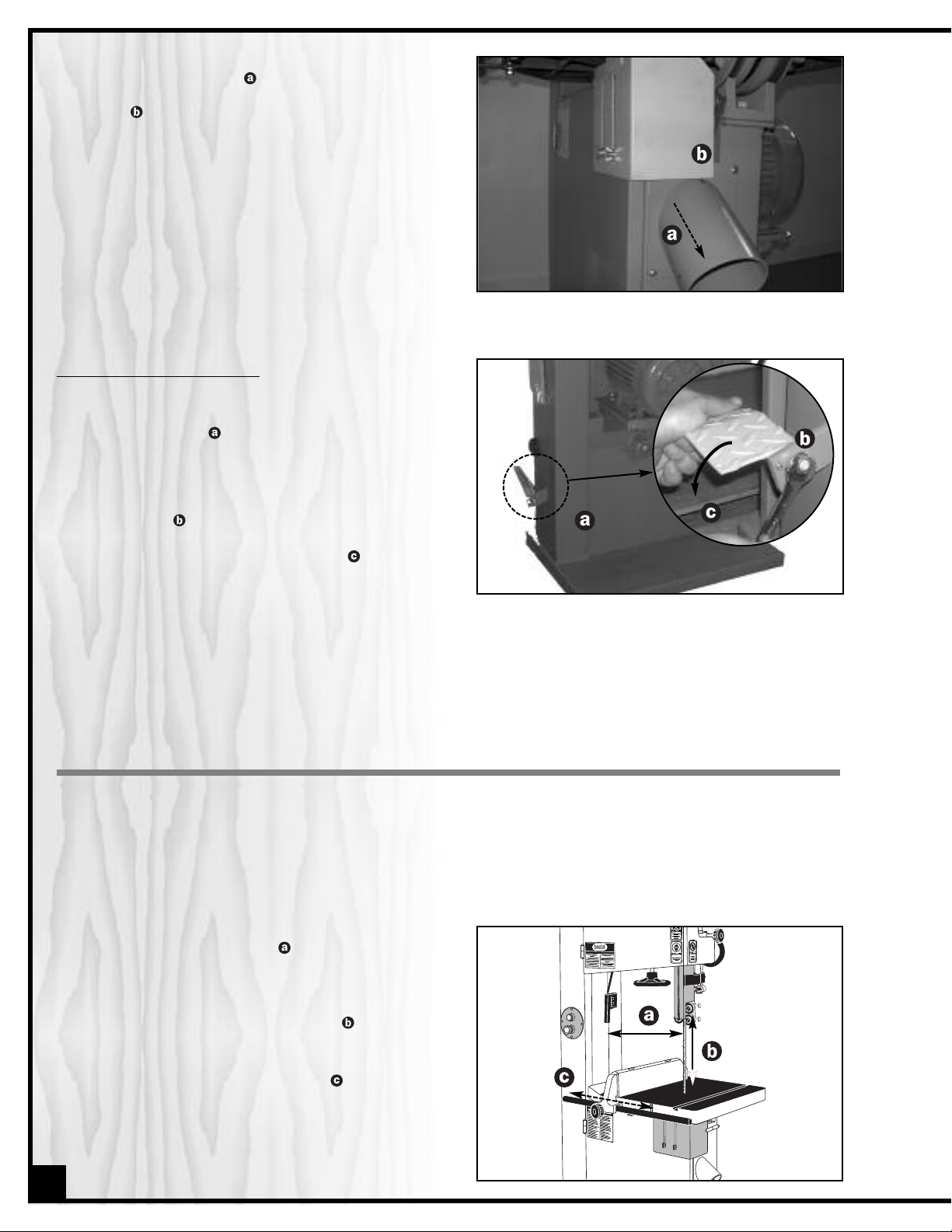
osition the dust port on the side panel, its open
P
3.
end facing downward , and attach it using the
four screws. Then, put the blade guard back in
place .
REPOSITIONNING THE FOOT BRAKE
To limit the potential for damage in transport, this
bandsaw is shipped from the factory with the the foot
brake pedal tilted up . To be operational, the pedal
must be tilted down as follows:
1. Loosen the bolt that attaches the foot brake pedal to the mounting bracket using a 14 mm open
end wrench .
2. Swivel the foot brake pedal manually .
3. Tighten the bolt to lock the foot brake pedal in
position.
BASIC FUNCTIONS OF THE UNIT
This 18" wood cutting bandsaw is supplied with a 1/2" wide general purpose blade and is designed to accommodate blade widths from 1/4" to 1". Ideal blade length for the model 90-270 is 153" (3886 mm) and ideal blade length
for the 90-270HD is 168 1/2" (4280 mm).
Note: Generally speaking, because the upper wheel height is somewhat adjustable (to allow for blade tensioning), a blade
length variation of plus or minus 1/2" from the “ideal blade length” can be accommodated on both models.
Maximum inboard width of cut (space between t h e
blade and the body of the saw ) is 17 1/4 " for both
models.
For cutting thicker stock or for resawing, the maximum
depth of cut (or max. workpiece height ) is 12 " for
the 90-270 and 18" for the 90-270HD.
A sturdy, cast iron, adjustable rip fence is supplied
to serve as a straightedge to guide the workpiece for
longer rip cuts. The fence can easily be removed and
set aside when not required, for example when making curved cuts.
10
Page 11
BASIC ADJUSTMENTS AND CONTROLS
CONNECTING TO A POWER SOURCE
SWITCH
OFF
Once the installation of a power cord and plug has
been completed, plug the power cord into an appropriate outlet. (Fig. 3) (Refer back to the section entitled
“ELECTRICAL REQUIREMENTS” on page 4, and make
sure all requirements and grounding instructions are
followed).
Contact a qualified electrician for the installation of a power plug and cord for connecting the bandsaw to a power source.
To avoid risk of shock or fire do not operate the unit with a damaged power cord or plug. Replace damaged cord or plug immediately.
To avoid unexpected or unintentional start-up, make sure that the power switch on the bandsaw is in the
OFF position before connecting to a power source.
MAGNETIC SWITCH
Make sure the switch is in the “OFF” position (red button has been pressed) before plugging in the power cord.
Fig. 3
This bandsaw is equipped with a MAGNETIC SWITCH,
, located at the front, on the frame of the machine.
This magnetic switch is designed to protect the unit
and the user from power surges, power outages and
unwanted or unintentional start-up.
The switch assembly is equipped with a GREEN “START”
button, , and a RED spring loaded “STOP” button, .
Once the RED “STOP” button has been pressed, the
machine can only be started by turning the inner part
of the button to the right to release the stop button.
FOOT BRAKE
The Foot brake is not designed as an emergency device. Always push on the “STOP” (RED) button to turn off the
motor before applying the foot brake.
This bandsaw is equipped with a FOOT BRAKE located
at the bottom of the machine . This device allows
for immediate immobilization of the blade once the
machine have been turned off (red button has
been pressed ).
11
Page 12

RECOMMENDED ADJUSTMENTS
TILTING THE TABLE
The table can be tilted to any angle from 0 to 45 degrees to the right, to allow for any type of bevel (or angle) cutting. The table tilt angle indicator is located on the back of the trunnion. To tilt the table:
Before making any adjustments, make sure that the switch is in the “OFF” position and that the power cord is
unplugged.
45°
1. Loosen the bolt underneath the table (only a
few turns), using the 19 mm combination wrench
provided.
Note: Be careful not to loosen the bolt too much or the
table tilt trunnion may become dislodged from the trunnion
support when you tilt the table.
ADJUSTING THE 90 DEGREE TABLE STOP AND RE-ALIGNING THE ANGLE POINTER
To ensure that your 90 degree cuts are square and that angled cuts are accurate with the angle indicator scale,
the table default position must be set to 90 degrees to the blade and the angle indicator pointer must be set to read
0 when the table is in the default (90 degree) position.
To adjust the 90 degree stop:
2. Manually tilt the table to the desired angle. Refer
to the scale under the table.
3. Tighten the bolt to secure the table in position.
1. Loosen the jam nut on the table stop bolt .
12
2. Place a combination square on the table
against the saw blade .
Page 13

3. Adjust the table angle manually until it is set to
90 degrees by making sure there is no space between the square and the blade or the table. To
allow for more or less table tilt, adjust the height of
the stop bolt until the head of the bolt just makes
contact with the frame of the saw when the table is
4. With the table set to 90 degree and the stop bolt at
the correct height, make sure the angle indicator
pointer is set to read 0 degrees . If the pointer
needs to be adjusted loosen the screw , adjust the
pointer to the 0 point on the scale and re-tighten
the screw to secure the pointer in place.
at 90 degree to the blade .
5. With the stop bolt set to the correct height and the pointer position properly aligned, tighten the jam nut (Refer
back to step 1) to secure the stop bolt in place. You will now be able to accurately return the table to the
90 degree position automatically without further adjustments and scale reading for any angle other than 0 will
be accurate.
REMOVING/INSTALLING THE BLADE
Before replacing or adjusting the blade, make sure the switch is in the “OFF” position and that the power cord is unplugged.
BLADE CLEARANCE
Note: When performing blade installation, removal, tensionning or tracking, maximum clearance between the
blade and both upper and lower bearing assemblies is
required to minimize friction, which would be damaging
to the blade.
Proceed as follows: Loosen the bolt .Then push on the
bearing assembly shaft going back as far as possible
for maximum blade clearance. Tighten the bolt to lock the
bearing assembly in place.
Repeat with lower bearing assembly.
1. Release blade tension by turning the blade tension
adjustment handwheel counter-clockwise until
it stops.
2. Remove the table aligning pin.
13
Page 14

Unscrew and remove the yellow blade guard.
3
.
4.
Turn the knob and open the upper door
turn the knob and open the lower wheel door .
. Then
5. Carefully pull the blade from the side slot
guard , and from the wheels . (Fig. 4)
Blade teeth are sharp. Use care when handling a
saw blade.
6. Pull the blade toward you, out of the table slot and
set it aside if it will be re-used or dispose of it safely if
it is worn or damaged.
, blade
Fig. 4
BLADE SELECTION
There are a variety of different types of bandsaw blades on the market to suit various cutting applications. Your
results may vary based on usage, experience and personal preference. Ask your local tool dealer for suggestions
for bandsaw blades (153" for model 90-270 and 168.5" for model 90-270HD) in 1/4" to 1" widths, based on what is
available in your area.
Some general guidelines to consider when choosing bandsaw blades:
•Wider blades with fewer teeth per inch are best suited to cutting straight lines, re-sawing and for sweeping
curves, but will not turn tight radius curves. They will cut quickly and aggressively but do have a tendency to
bind (or get stuck in the cut) if turned too sharply.
•Narrower, thinner blades with more teeth per inch will cut more slowly but can turn much tighter corners for
cutting more intricate work.
Common causes of blade breakage:
• Poor guide bearing alignment and adjustment.
• Forcing or twisting a wide blade around a short radius.
• Feeding the workpiece too quickly.
• Dull teeth.
• Too much blade tension.
•Setting blade guard assembly too high above the work-piece.
•Lumpy or improperly finished braze or weld on the blade.
•Continuous running of blade when not cutting.
BLADE INSTALLATION
To install a blade, repeat the previous steps in reverse
order, making sure that the blade is installed with the
teeth pointing forward and down .
With the blade properly installed, proceed to “BLADE
TENSION ADJUSTMENTS” and “BLADE TRACKING ADJUSTMENTS”, pages 15 and 16.
14
Proper installation
Improper installation
Page 15

ADJUSTING BLADE TENSION
Determining ideal blade tension is somewhat subjective. It is learned through practice and experience and is
somewhat dependant on personal preference and individual work habits.
A properly tensioned blade is critical to obtaining maximum performance from any bandsaw. A properly tensioned
blade will last longer and be much less likely to break prematurely. If the blade tension is too loose you will notice
that the blade will have a tendency to drift or slip off-line when cutting and you will have more difficulty controlling
our cuts. A blade that is tensioned too tightly will break prematurely and will be difficult to work with when making
y
tighter radius cuts.
The following information can be used as a guideline or starting point to assist you in determining ideal blade tension for your needs:
•
When working with wider blades, re-sawing taller stock, making straight cuts or wide sweeping curves tighter blade tensions will provide better results.
•
When working with narrower blades, sawing shorter stock and making tighter curved cuts are best per
formed using less tension.
To adjust blade tension proceed as follows:
Before making blade tension adjustments, make sure that the switch is in the “OFF” position and that the power
cord is unplugged.
INCREASE
DECREASE
1. Turn the blade tension adjustment handwheel
clockwise to increase tension and counter-clockwise to decrease tension
2. With the saw turned off and the blade tensioned to
where you feel it should be, press against the side
of the blade to test the tautness of the blade .
For ideal results with most blade widths and cutting
applications the blade should flex in no more than
1/4" to 3/8". (Fig. 5)
3. Make a test cut on a sample piece of wood and if
needed re-adjust the blade tension.
Note: the blade tension indicator scale can be used
as a reference – the higher the number on the scale
(shown in millimetres of spring tension) the tighter the
tension on the blade. Take note of ideal setting with various blade widths for reference the next time that blade
is used or when a similar type of cut is to be performed.
Fig.5
To prolong the life of the blade whenever the band saw is not in use for prolonged periods (more than 24 hours),
release the blade tension lever to remove tension from the blade, Over time, maintaining tension on a blade that
is not in use will cause the blade to deform, by taking the shape of the wheels at both extremities. This can weaken
the blade and cause premature breakage.
15
Page 16

BLADE TRACKING ADJUSTMENTS
Ideally, the blade should stay relatively centered on both
the upper and lower wheels (Fig. 6).
3 MM - 1/16"
Due to natural variations in castings, blade thickness or
density and tire wear, absolute perfect centering alignment is rarely attainable. A slight misalignment of the
blade on the wheels is inevitable and as long as it is kept
to a minimum (following the steps listed below) will not hinder the performance of the saw.
This misalignment is controlled and kept to a minimum primarily by adjusting the tilt angle of the upper wheel.
When adjusting blade tracking to center the blade on the
Fig. 6 Fig. 7
wheels and assuming that perfect centering is not attainable, it is preferable to have the blade slightly off-center
towards the front of the wheels rather than towards the rear because the teeth on most band saw blades have alternating hook (one inner, one outer) – therefore if the blade is centered too far back on the wheel (or if the blade tension is too tight), inner hooked teeth will dig into the wheel tire and cause premature wear of the tire.
Nonetheless, to avoid having the blade come off of the wheels on it’s own during operation, the front edge of the
blades teeth should never be any closer than 3mm (1/16”) from the front edge of the wheel (Fig 7).
BLADE CLEARANCE
Note: As previously stated, when performing blade installation, removal, tensionning or tracking, maximum clearance
between the blade and both upper and lower bearing assemblies is required to minimize friction, which would be
damaging to the blade. Refer back to page 13 and follow the instructions for “BLADE CLEARANCE” before performing
blade tracking adjustments.
1. Open the upper wheel cover door
then rotate the
wheel slowly forward by hand and check (through
the window .of the upper wheel ) the position of the
blade on the wheel.
The blade should remain as cen-
tered as possible on the wheel as it turns . (Fig. 8)
2. If the blade tracking must be adjusted, loosen the jam
nut on the tracking adjustment knob , using a
14 mm open end wrench, then turn the knob: (Fig. 9)
A) Clockwise if the blade moves toward the front of
the wheel (Fig. 10). This tilts the top of the wheel to
Fig. 8
the back and moves the blade toward the center.
B) Counter- clockwise If if the blade moves toward
the back edge (Fig. 10). This tilts the top of the
wheel to the front and moves the blade toward
the center.
Note: Turn the tracking knob in 1/2 turn increments, re-check
and adjust again as needed.
Turn CW if
moves to
blade
front
3. With the tracking set, tighten the jam nut to secure the
tracking adjustment knob in place.
16
Fig. 9
Turn CCW
if blade
moves to
back
Fig. 10
Page 17

Note: The upper and lower wheels are factory set to allow
for easy and optimal blade tracking adjustments using the
primary blade tracking adjustment knob, which adjusts
the angle of tilt of the upper wheel. In extremely rare
cases, if acceptable blade tracking cannot be attained
through the primary adjustment it may eventually become
necessary to make minor adjustments to the angle of tilt of
the lower wheel. The four bolts may be adjusted in or
out to tilt the lower wheel up/down or left/right as needed.
ADJUSTING THE BLADE GUARD FOR DEPTH OF CUT
The blade guard can be moved up or down to accommodate the height of the work to be cut. To prevent the
blade (which is flexible and which would not otherwise be supported ) from slipping out of position during cutting,
and to reduce risks of injuries, a minimum amount of blade should be exposed
The blade guard should be set 1/8” - 1/4” above the workpiece to prevent the blade from flexing out of position or
off-line during cutting.
Adjust the height of the blade guard to suit the thickness of the workpiece as follows:
.
RAISE
LOWER
1. Loosen the lock knob .
2. Turn the handwheel clockwise to raise or counter
clockwise to lower the blade guard.
3. Re-tighten the lock knob before turning on the saw.
WORK PIECE
1/8” - 1/4”
ADJUSTING THE UPPER AND LOWER BLADE GUIDES AND SUPPORT BEARINGS
The blade guides keep the blade from moving from side to side during cutting and must be snug but not touching
the blade in order to ensure accurate cuts. The support bearings keeps the blade from moving back and out of
position when the work is being fed into the blade and must be very close to the back of the blade to prevent damage to the blade during cutting. Adjust as follows:
To avoid injury, make sure that the switch is in the “OFF” position and that the power cord is unplugged before performing any adjustments on the bandsaw.
Note: Before adjusting the upper and lower blade guides and support bearings, make sure the blade is tensioned and
tracking properly. Adjust the upper and lower blade guides and support bearings after each blade tension and tracking
adjustment. Whenever the upper blade guide and support bearing are adjusted, the lower blade guide and support bearing should also be adjusted.
17
Page 18

POSITIONING THE UPPER/LOWER BLADE GUIDES AND SUPPORT BEARING ASSEMBLIES
The upper/lower blade guides and support bearing are both assembled as one unit which can be moved back or
forward. To prevent damage to the blade, the blade guide bearings must remain behind the blade teeth during
operation.
P
roceed as follows:
1.
Loosen the bolt
2
. Move the assembly bracket forward along the
shaft , until the blade guide bearings are at least
1
/32" behind the blade teeth , (do not protrude
past the hollowed part of the teeth of the blade.
3.
Tighten the bolt to lock the assembly in place.
.
1/32"
POSITIONING THE UPPER/LOWER BLADE GUIDES
The blade guides keep the blade from moving from side to side during cutting and must be snug but not touching the
blade in order to ensure accurate cuts. The space between each bearing and the blade must not exceed 0.02" (the
thickness of a sheet of paper ). If less space is left, the blade will get stuck or jammed between both bearings. Too much
friction will cause blade to overheat and break.
Adjust the positionning of the blade guides as follows:
1. Loosen the two bolts with a 12 mm open end
wrench.
3. Loosen the two bolts on the blade guides/support
bearing assembly mounting bracket.
18
2. Use a flat head screwdriver to make a quarter of a
turn toward the outside to both guide bearings ,
so as to obtain maximum blade clearance.
4. Move the bracket left or right along the bolts , until
the blade is centered between both guide bearings.
Page 19

5. Make a quarter of a turn (approx) toward the inside
, so as to obtain a space of 0.02" (the thickness of
a sheet of paper) between both bearings and the
blade .
Tip: Place a feeler gauge or sheet of paper between each
guide bearing and the blade to make sure there is a
space.
6
. Tighten the bolts to lock the guide bearings in po-
s
ition.
0.02"
0.02"
0.02"
POSITIONING THE UPPER/LOWER SUPPORT BEARINGS
The support bearings keeps the blade from moving back and out of position when the work is being fed into the
blade and must be very close to the back of the blade to prevent damage to the blade during cutting.
Adjust the positioning of the upper/lower support bearing as follows:
1/64"
1. Loosen the bolt with a 12 mm open end wrench.
2. Move the support bearing shaft in or out , until
the support bearing barely touches the blade (is
1/64" behind the back of the blade) .
3. Tighten the bolt to lock the support bearing in position.
OPERATING INSTRUCTIONS
CHECKLIST BEFORE STARTING
NOTE: Now that you have completed the four adjustment steps which are an essential part of safe, accurate bandsaw operation, it would be a good idea to make yourself a checklist as follows to ensure that each adjustment to the bandsaw is
made in the proper order starting with the general safety precaution:
1. Turn off the bandsaw and unplug the power cord.
2. Adjust blade tension.
3. Adjust blade tracking.
4. Adjust upper blade guides and support bearing.
5. Adjust lower blade guides and support bearing.
19
Page 20

These additional safety measures should be be included in your checklist:
6. Make sure all the blade guards are in place.
7. Make sure the bandsaw table and work area in general are clean and free of sawdust and debris.
These steps should always be followed when any adjustment is performed, the blade is changed, or periodically as vibration and normal wear and tear on the machine could throw these parts out of alignment.
CONNECTING TO A DUST COLLECTOR
dust port with a 4” opening is provided
A
to accommo-
date connection to a dust collector (not included).
Once the dust port has been installed (See Previous
section “ASSEMBLY INSTRUCTIONs”), be sure to use
appropriate sized hose and fittings (not included) and
check that all connections are sealed tightly to help
minimize airborne dust.
If you do not already own a dust collection system consider contacting your General® International distributor
for information on our complete line of dust collection
systems and accessories or visit our Web Site at:
www.general.ca.
OPERATIONS STEP-BY-STEP
To reduce the risk of damage to the bandsaw or the workpiece, as well as a potential for personal injury, after initial set-up as well as before each use, make sure that everything is securely installed and that all fasteners and
moving parts on this bandsaw are locked in place before starting the machine.
Trace the cutting line on your workpiece with a pencil.
1.
2. Set the height of the blade guard according to the thickness of your workpiece (see section: “ADJUSTING THE
BLADE GUARD FOR DEPTH OF CUT” on page 17.)
3. If a dust collector is connected to your bandsaw, turn it on.
Make sure to have on safety glasses at all times when using the bandsaw.
Make sure you are wearing safe appropriate workshop attire. Roll up long sleeves, secure long hair and remove
any jewelry: watches, rings, bracelets or anything that could get stuck into the moving parts of the bandsaw,
potentially causing serious injuries.
4. Press the green "ON" button to start the bandsaw.
Note: The red inner part of the red "OFF" button must first be turned to the right to release the stop button.
5. Align the cutting line on your workpiece with the blade.
Tip: The use of a roller stand provides an extra support for more convenience when working with longer workpieces.
20
Page 21

TO STOP THE MACHINE
1. Press the red “OFF” button at the front of the frame of the bandsaw to stop the motor.
2. Apply the foot brake to immobilize the blade.
3. Turn your dust collector off.
INSTALLING/USING THE RIP FENCE
For more precise straight line cuts there is a removable rip fence that can be installed on the rail of the bandsaw
table. Proceed as follows:
1. Set the fence down on the rail either at the left
or right of the saw blade.
Note: For short workpieces that fit between the frame of
the saw and the blade , position the fence at the left
side of the blade. For cutting longer or wider workpieces,
position the fence, on the right side of the saw blade.
Turn the knob clockwise to lock the fence in
3.
place.
Make sure to lock the fence in place before
starting to cut against the rip fence.
Adjust the positioning of the fence on the rail
2.
so that the distance from the inside face of the rip
fence to the blade matches the required
width of cut.
21
Page 22

CUTTING CURVES
• When cutting curves, carefully turn the workpiece so the blade follows without twisting. If the curve is so sharp that
you repeatedly back up and cut new kerf, use a narrower blade, or a blade with more set (teeth further apart).
When a blade has more set, the workpiece turns easier but the cut is rougher.
• When changing a cut, do not withdraw the workpiece from the blade. The blade may get drawn off the wheels.
• To change a cut, turn the workpiece and cut your way out through the waste material area.
• When cutting long curves, make relief cuts as you go along.
CUTTING CIRCLES
1. Adjust the blade guard assembly to 1/8" above the
workpiece.
2. Use both hands while feeding the work into the blade.
Hold the workpiece firmly against the table. Use gentle
pressure. Do not force the work. Allow the blade to cut.
3. The smallest diameter circle that can be cut is determined by the width of the blade. For example, a 1/4"
wide blade will cut a minimum diameter of approximately 1-1/2" .
MIN. CIRCLE
DIAM.
BLADE WIDTH
LUBRICATION
Disconnect machine from power source, before performing any lubrication or maintenance.
Note: Open the upper door to
access the blade tension screw
Keep blade tension screw , shafts and joints , as well as the rack and pinion greased and free of dust or
debris. Clean and remove dust, debris, and old grease after every 10-15 hours of use. After cleaning, reapply
grease as needed. (Use any all purpose grease.)
The motor and all bearings are sealed and permanently lubricated – no further lubrication is required. No other
part of this bandsaw needs lubrication.
22
Page 23

PERIODIC MAINTENANCE
Never operate the bandsaw with any damaged part. Replace a damaged part at the first visible signs of damage.
1. Inspect/test the ON/OFF switches before each use. Do not operate the bandsaw with a damaged
switch; replace a damaged switch immediately.
2. Periodically inspect the power cord/plug/blade for damage.
To avoid eye injury from blowing debris, wear safety goggles when blowing out sawdust.
3. Keep the machine clean and free of sawdust. Frequently blow out or vacuum up the sawdust and wipe down
the machine occasionally with a damp rag.
Note: The wheels must always be kept clean. Dirt on the wheels will cause blade slippage.
4. Do not allow dirt, pitch or gum to build up on the table, blade, guide/support bearings. Clean as needed with
gum and pitch remover.
Note: Do not immerse the bearings in the gum and pitch remover.
To prevent rust and
5.
lar applications of any after-market surface protectant or rust inhibitor such as General International “Top Saver”
item #GC-010. (See Section “RECOMMENDED OPTIONAL ACCESSORIES FOR YOUR BANDSAW” on page 26.)
so that the wood slides easily while cutting
, apply a light coating of paste wax or use regu-
REQUIRED MAINTENANCE
REPLACING THE BANDSAW BLADE
The blade should be replaced when worn out.
Refer to the following symptoms to determine whether or not it is time to replace the blade :
- It is not cutting as fast.
- It is not able to follow a cutting line as it used to.
REPLACING THE UPPER AND LOWER BLADE GUIDES/SUPPORT BEARINGS
Bearings should be verified each time the blade is replaced. Check if they turn well. If not,
or jammed between them and will wear
To replace the bearings, loosen and remove the bolts. (See Section “
on page 18 and Section”POSITIONING THE UPPER/LOWER SUPPORT BEARING” on page 19.
prematurely.
POSITIONING THE UPPER/LOWER BLADE GUIDES”
the blade will get stuck
REPLACING THE WHEEL TIRE
Wheels tires must be replaced if they get worn out or damaged. (If it is worn out, the blade will not track straight on
the wheels.) You can replace the tires yourself. But given that the replacement of this part is complex, the tire
being sealed on the gasket of the wheel, you may prefer to contact our Parts and Service department at:
Tel.: (514) 326-1161
orderdesk@general.ca
23
Page 24

ADJUSTING THE LOWER WHEEL BRUSH
The lower wheel of both 90-270 and 90-270HD models are equipped with a cleaning brush that prevents pitch and sawdust build up on the lower tire.
Any pitch and sawdust that builds up on the upper wheel tire should be removed with a stiff brush or scraped off with
a piece of wood.
NOTE: To avoid damaging the tire do not use a sharp knife or any kind of solvent to remove pitch build up.
Verify that the brush keeps the lower wheel surface clean at all times. With use and normal wear over time, the brush
hairs will soften and will not clean the surface of the wheel as well. You then must lower the brush slightly. Proceed
as follows:
1. Loosen the bolt with a 12 mm open end wrench.
2. Slide the brush slightly down along the mounting hole
, so that a fresh, stiffer part of the hairs touches the
wheel tire.
Tip: Cut the dull ends of the brush if they are too worn out to
properly clean the wheel.
3. Tighten the bolt to lock the brush in position.
REPLACING LOWER WHEEL MOTOR BELT(S*)
*The lower wheel on Model 90-270 is driven by one belt while the lower wheel on Model 90-270HD is driven by two belts
The lower wheel is driven by (a) belt
(s*)
mounted on pulley powered by the motor. The belt(s*) tension s
verified upon reception of the machine, then every 6 months. Slighlty push on the belt(s*) with your finger. The belt(s*)
must not move more than 1/8" .
If the belt
(s*)
becomes too loose due to wear or if a breakage occurs, you must
replace it (them*) as follows:
1.
Loosen (but do not remove) the nut
the back of the motor plate. This will loosen the motor
belt(s*).
located at
2. Loosen the bolt
wheel, using a 12 mm open end wrench, then remove
the wheel.
located in the middle of the lower
hould be
1/8” Max.
24
3. Install (a) new belt(s*).
4. Reinstall the wheel.
5. Tighten the bolt.
Page 25

REPLACING THE MOTOR
Should the motor require replacement, proceed as follows:
Never attempt to repair the motor yourself. Contact a qualified technician.
MOTOR UNDERSIDE VIEW
MOTOR HANDLING - #
The motor on model 90-270HD is very heavy. Do not
over-exert. The help of at least one assistant will be
needed for the following step. Ideally, a hoist should
be used for lifting the motor. A hoisting eyebolt is
attached to the motor for this purpose.
90-270HD ONLY
NOTES
REMOVING MOTOR - 90-270 & 90-270HD
Loosen the nut under the motor support plate , and
remove the bolt . Then, remove the nut behind the
motor support plate and remove the bolt .
Removing those two bolts will loosen the motor pulley’s
belt(s*). Remove the belt(s*). You will then be able to
remove the entire motor assembly.
25
Page 26

RECOMMENDED OPTIONAL
ACCESSORIES FOR YOUR
BANDSAW
We offer a large variety of products to help you
increase productivity, accuracy and safety
when using your bandsaw. Here’s a small sampling of accessories available from your local
General International dealer.
For a complete list, visit our website at
www.general.ca.
Dust Collector
We have a wide selection
of dust collectors to suit all
your shop needs. Dust
collectors contribute to a
cleaner and more
healthful workshop
environment.
“TOP SAVER” cleaner
item #GC-010
All in one, table top rust
remover and lubricant. /
Reduces friction and prevents binding. / Removes
and inhibits rust and corrosion. / Repels dust and
moisture.
Roller Stand
item #50-150
item #50-160
item #50-170
We offer a selection of
roller stans to suit all your
shop needs.
Power feeder
Model #20-890
Light and convenient
feeder, suitable for 16”
to 28” bandsaws.
26
Page 27
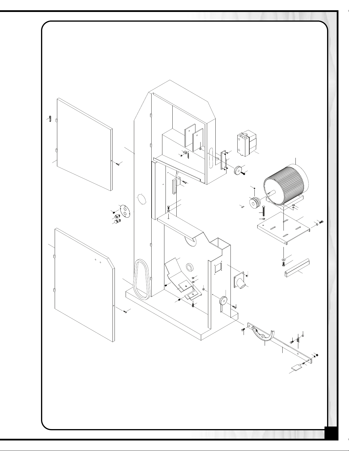
2
3
4
47
46
48
49
43
52
50
51
44
45
6
7
30
31
24
28
27
8
26
25
29
5
23 *
40
39
42
41
5
1 *
35
34
8
38 *
53
53-1
6
7
12
11 *
21
10
20
15
14
13
20
19
22
17
16
36
37
32
33
9 *
FRAME ASSEMBLY
*Not identical between both models (note: correct # based on model before ordering.)
27
Page 28

28
PARTS LIST
0-270
9
PART N0. REF. N0. DESCRIPTION SPECIFICATION QTY
FRAME ASSEMBLY
90270-01 1 FRAME (FOR MODEL 90-270) 1
0270HD-01 1 FRAME (FOR MODEL 90-270HD) 1
9
90270-02 2 HINGE PIN 4
90270-03 3 UPPER DOOR 1
90270-04 4 LOWER DOOR 1
90270-05 5 SOCKET HEAD SCREW 1/4-20 X 3/8" 2
90270-06 6 DOOR LOCK KNOB 1/4-20 X 3/4" 2
90270-07 7 SOCKET HEAD SCREW 1/4" 2
90270-08 8 NUT 1/4 2
90270-09 9 MOTOR (FOR MODEL 90-270) 3HP 1
0270HD-09 9 MOTOR (FOR MODEL 90-270HD) 5HP 1
9
90270-10 10 KEY 8 X 8 X 45 1
90270-11 11 MOTOR PULLEY (FOR MODEL 90-270) 2-1/2"A1 X 24 X 8 1
90270HD-11 11 MOTOR PULLEY (FOR MODEL 90-270HD) 2-1/2"A1 X 28 1
90270-12 12 MOTOR PULLEY FIXING SCREW 5/16-18 X 1/2" 2
90270-13 13 MOTOR BASE 1
90270-14 14 HEX HEAD BOLT 3/8 X 1-1/2 1
90270-15 15 NUT 1/4 1
90270-16 16 HEX HEAD BOLT 3/8 X 1-1/4 4
90270-17 17 FLAT WASHER 3/8" 4
90270-19 19 NUT 3/8" 4
90270-19-1 19-1 LOCK WASHER 3/8" 4
90270-20 20 HEX HEAD BOLT 3/8" X 4" 1
90270-21 21 NUT 3/8" 1
90270-22 22 MOTOR BASE SUPPORT BRACKET 1
90270-23 23 V-BELT (FOR MODEL 90-270) A36 1
90270HD-23 23 V-BELT (FOR MODEL 90-270HD) A38 2
90270-24 24 DUST CHUTE 1
90270-25 25 WOODEN DUST BOARD 1
90270-26 26 HEX HEAD BOLT 5/16"-18 X 3/4" 2
90270-27 27 WASHER 5/16" 2
90270-28 28 NUT 5/16" 2
90270-29 29 PHILLIPS HEAD SCREW 3/16 X 3/8" 2
90270-30 30 DUST PORT 1
90270-31 31 PHILLIPS HEAD SCREW 3/16 X 3/8" 4
90270-32 32 BLADE TENSION INDICATOR 1
90270-33 33 CAP SCREW 3/16 X 1/2 2
90270-34 34 WIRE BRACKET 5 X 50 X 13 1
90270-35 35 PHILLIPS HEAD SCREW 3/16 X 3/8 1
90270-36 36 HEX HEAD BOLT 3/8"-16 X 2" 1
90270-37 37 NUT 3/8"-16 1
90270-38 38 SWITCH BOX (FOR MODEL 90-270) 1
90270HD-38 38 SWITCH BOX (FOR MODEL 90-270HD) 1
90270-39 39 ON SWITCH 30MM 1
90270-40 40 OFF SWITCH 30MM 1
90270-41 41 POWER CONTROL PANEL 2 X 160 X 160 1
90270-42 42 PHILLIPS HEAD SCREW 3/16 X 3/8 4
90270-43 43 CONNECTION PLATE 9 X 38 X 520MM 1
90270-44 44 BRAKE SHOE 1
90270-45 45 HEX HEAD BOLT 3/8"-16 X 1" 1
90270-46 46 HEX HEAD BOLT 1/4"-20 X 1/2" 1
90270-47 47 FOOT BRAKE PEDAL 1
90270-48 48 LOCK WASHER 3/8" 1
90270-49 49 NUT 3/8"-16 1
90270-50 50 SPRING 2.0 X 15 X 120L 1
90270-51 51 NUT 3/8"-16 1
90270-52 52 HEX HEAD BOLT 3/8"-16 X 3/4" 1
90270-53 53 PLASTIC PLATE 1
90270-53-1 53-1 PHILLIPS HEAD SCREW 3/16" X 1/4" 4
Page 29

5 5
3
6
1
6
2
6
0
6
4
8
8
2
8
9
7
8
7
5
7
7
7
6
7
6
5
5
7
9
5
5
8
8
0
7
6
6 6
7
0
0
9
9
8
6
5
5
7
8
5
9
8 8
7
8
6
8
5
8
8
1
6
6
2
6
3
8
0
5
4
7
3
7
2
7
1
7
9
6
8
6
0
6
3
6
4 *
6
5 4 *
*Not identical between both models (note: correct # based on model before ordering.)
WHEEL ASSEMBLY
29
Page 30

PARTS LIST
0-270
9
PART N0. REF. N0. DESCRIPTION SPECIFICATION QTY
WHEEL ASSEMBLY
90270-54 54 SAW BLADE (FOR MODEL 90-270) 1/2 " X 3886 MM 1
90270HD-54 54 SAW BLADE (FOR MODEL 90-270HD) 1/2 " X 4280 MM 1
90270-55 55 UPPER WHEEL 1
90270-56 56 UPPER WHEEL SHAFT 1
90270-57 57 BEARING 6205ZZ 2
90270-58 58 INNER BUSHING 2
90270-59 59 OUTER BUSHING 2
90270-60 60 C RING R52 2
90270-61 61 FLAT WASHER R52 2
90270-62 62 HEX HEAD BOLT 3/8"-16 X 3/4" 2
90270-63 63 NEOPHRENE TIRE 2
90270-64 64 LOWER WHEEL (FOR MODEL 90-270) 1
90270HD-64 64 LOWER WHEEL (FOR MODEL 90-270HD) 1
90270-65 65 LOWER WHEEL SHAFT 1
90270-66 66 BRUSH BRACKET 1/4 X 1-1/2 X 105MM 1
90270-67 67 BRUSH 1
90270-68 68 HEX HEAD BOLT 5/16"-18 X 1" 1
90270-69 69 FLAT WASHER 5/16" 1
90270-70 70 NUT 5/16"-18 1
90270-71 71 FLAT WASHER 50MM 1
90270-72 72 HEX HEAD BOLT 3/8"-16 X 1" 1
90270-73 73 HEX HEAD BOLT 3/8"-16 X 1-1/4" 4
90270-74 74 NUT 3/8"-16 4
90270-75 75 ARBOR BRACKET 1
90270-76 76 HEX HEAD BOLT 3/8"-16 X 1/4" 1
90270-77 77 NUT 3/8"-16 1
90270-78 78 BLADE TENSION SUPPORT SHAFT 5/8 X 342-130 1
90270-79 79 THRUST BEARING 51103 1
90270-80 80 BEARING 6205LLB 2
90270-82 82 INDICATOR WIRE PULLER 5/8'' 1
90270-83 83 SPRING YM35 X 50 1
90270-84 84 TENSION BRACKET 1
90270-85 85 NUT 3/8"-16 2
90270-86 86 FLAT WASHER 3/8'' X 4MM 2
90270-87 87 TENSION BRACKET SHAFT 1
90270-88 88 NUT 3/8"-16 2
90270-89 89 TENSION ADJUSTMENT HANDWHEEL 6" X 5/8 1
90270-90 90 SET SCREW 5/16"-8 X 1/2" 1
NOTES
30
Page 31

120
121
140
141
142
93
91
94
92
96
95
135
137
137
136
134
133
135
137
138
134
134
106
107
105
103
104
102
98
99
97
101
100
135
135
137
138
136
137
134
134
134
134
128
127
131
132
129
128
130
133
122 *
113
123
126
125
124
1
15
119
118
114
139
117
116
113
108
112 *
109
110
111
TABLE ASSEMBLY
*Not identical between both models (note: correct # based on model before ordering.)
31
Page 32

PARTS LIST
90-270
PART N0. REF. N0. DESCRIPTION SPECIFICATION QTY
TABLE ASSEMBLY
90270-91 91 TABLE 1
90270-92 92 FENCE RAIL 25MM X 610MM 1
90270-93 93 HEX HEAD BOLT 3/8"-16 X 1" 2
90270-94 94 FLAT WASHER 3/8" 2
90270-95 95 FENCE 1
90270-96 96 FENCE LOCK KNOB 3/8 X 31 1
90270-97 97 TRUNNION 1
90270-98 98 HEX HEAD BOLT 3/8-16 X 1-1/4 4
90270-99 99 LOCK WASHER 3/8" 4
90270-100 100 HEX HEAD BOLT 1/2"-12 X 1-3/4" 1
90270-101 101 FLAT WASHER 1/2” X 4MM(T) 1
90270-102 102 TRUNNION BASE 1
90270-103 103 HEX HEAD BOLT 1/2"-12 X 1" 2
90270-104 104 LOCK WASHER 1/2" 2
90270-105 105 BLADE GUIDE SUPPORT FORK 1
90270-106 106 HEX HEAD BOLT 5/16"-18 X 3/4" 1
90270-107 107 FLAT WASHER 3/8" 1
90270-108 108 SHAFT CAP 1
90270-109 109 HEX HEAD BOLT 5/16-18 X 1" 3
90270-110 110 LOCK WASHER 5/16" 3
90270-111 111 LOCK KNOB 3/8" X 60 1
90270-112 112 BLADE GUARD SHAFT (FOR MODEL 90-270) 1
90270HD-112 112 BLADE GUARD SHAFT (FOR MODEL 90-270HD) 30 X 690MM 1
90270-113 113 C RING S-30 2
90270-114 114 PINION 1
90270-115 115 PINION BASE 1
90270-116 116 HEX HEAD BOLT 5/16-18 X 3/4" 3
90270-117 117 LOCK WASHER 5/16" 3
90270-118 118 BLADE GUARD ADJUSTMENT HAND WHEEL 5" X 18 1
90270-119 119 SPRING PIN 4 X 30 1
90270-120 120 TRACKING ADJUSTMENT KNOB 3/8" X 70 1
90270-121 121 NUT 3/8" 1
90270-122 122 BLADE GUARD (FOR MODEL 90-270) 1
90270HD-122 122 BLADE GUARD (FOR MODEL 90-270HD) 665MML 1
90270-123 123 BLADE GUARD BRACKET 6.0 X 38 X 135 1
90270-124 124 HEX HEAD BOLT 1/4"-20 X 1/2" 3
90270-125 125 LOCK WASHER 1/4" 3
90270-126 126 FLAT WASHER 1/4" 3
90270-127 127 BLADE GUIDE HOLDER 1
90270-128 128 HEX HEAD BOLT 5/16"-18 X 1" 1
90270-129 129 FLAT WASHER 5/16" 2
90270-130 130 HEX HEAD BOLT 5/16"-18 X 3/4" 1
90270-131 131 BLADE GUIDE ADJUSTMENT BRACKET 1
90270-132 132 ADJUSTMENT BRACKET ARBOR 1
90270-133 133 BLADE GUIDE BASE 2
90270-134 134 HEX SOCKET BOLT 5/16"-18 X 3/4" 8
90270-135 135 C RING S15 6
90270-136 136 GUIDE BEARING EXCENTRIC SHAFT 4
90270-137 137 GUIDE BEARING 6202LLB 10
90270-138 138 THRUST BEARING SHAFT 2
90270-139 139 FLAT WASHER 5/16" 3
90270-140 140 PHILLIPS HEAD SCREW 3/16 X 3/8 2
90270-141 141 WIRE 720MM 1
90270-142 142 TABLE PIN 8 X 38(1-1/2) 1
32
Page 33

1
6
5
6
6
1
*
*
*
*
*
*
GUARDS
*Not identical between both models (note: correct # based on model before ordering.)
33
Page 34

PARTS LIST
0-270
9
PART N0. REF. N0. DESCRIPTION SPECIFICATION QTY
GUARDS
90270-143 143 WING NUT 1/4" 2
90270-144 144 FLAT WASHER 1/4 2
90270-145 145 LOWER GUARD 1
90270-146 146 LOCK WASHER 1/4" 2
90270-147 147 HEX HEAD BOLT 1/4 X 1/2 2
90270HD-148 148 HEX HEAD BOLT (MODEL 90-270HD ONLY) 1/4 X 1/2 1
90270HD-149 149 FLAT WASHER (MODEL 90-270HD ONLY) 1/4" 1
90270HD-150 150 TENSION SPRING (MODEL 90-270HD ONLY) 1
90270HD-151 151 BUSHING (MODEL 90-270HD ONLY) 1
90270HD-152 152 FLAT WASHER (MODEL 90-270HD ONLY) 3/8” X 5TMM 1
90270HD-153 153 HEX HEAD BOLT (MODEL 90-270HD ONLY) 3/8” X 3 1
90270-154 154 CABLE 720MM 1
90270-155 155 CABLE STOP 1
90270-156 156 PHILLIPS HEAD SCREW 1
90270-157 157 TERMINAL STRIP 1
90270-158 158 FLAT WASHER 12 X 5.2MM 2
90270-159 159 NUT 3/16 X 8MM 2
90270-160 160 STUD 2
90270-161 161 JUNCTION BOX 1
90270-162 162 STRAIN RELIEF 2
90270-163 163 FLAT WASHER 12 X 5.2MM 2
90270-164 164 NUT 3/16 X 8MM 2
90270-165 165 COMBINATION OPEN END WRENCH 17 X 19 1
90270-166 166 EYE BOLT 1
NOTES
34
Page 35

NOTES
35
Page 36

90-270
8360, Champ-d’Eau, Montreal (Quebec)
Canada H1P 1Y3
Tel.: (514) 326-1161
Fax : (514) 326-5565 Parts & Service
Fax : (514) 326-5555 Order Desk
orderdesk@general.ca
www.general.ca
IMPORTANT: When ordering replacement parts, always give the model number, serial number of
the machine and part number. Also a brief description of each item and quantity
desired.
 Loading...