

Page 1

Cast-iron frame & precision balanced
aluminum wheels with replaceable
rubber tires.
2 cutting speeds for excellent results in
either hard or soft wood.
Precision blade guide bearing included.
Aluminum miter gauge with handle.
Large, stable cast iron table and slide out
steel extension wing.
Laser line marker and goose neck style
work light included. (Bulb for work light not
included)
Smooth running, durable 1/2 HP motor.
Safety lock-out switch with removable key
to prevent unauthorized use.
Built-in blade cleaning brush keeps tires
free of dust and chips.
Telescoping extension table with
retractable fence attachment.
WHEEL SIZE
12” (316 mm)
WHEEL SPEEDS (2)
483 & 825 RPM
BLADE SPEEDS (2)
1580 & 2710 FPM (480& 820 MPM)
MAXIMUM BLADE WIDTH
1⁄2” (13 mm)
MINIMUM BLADE WIDTH
1⁄8” (3.2 mm)
BLADE LENGTH
80” (2032 mm)
TABLE SIZE
13” x 13” (330 x 330 mm)
TABLE SIZE WITH EXTENSION
20” x 13” (508 x 330 mm)
TABLE TILT
0° TO 45° (RIGHT)
TABLE HEIGHT
38 3⁄4 (985 mm)
MAXIMUM WIDTH OF CUT
12” (305 mm)
MAXIMUM DEPTH OF CUT
5” (127 mm)
DUST PORT
2 1⁄2” (63 mm)
BASE DIMENSIONS
30” x 21” (710 x 540 mm)
MOTOR
1⁄2 HP, 110 V, 7 A
WEIGHT
154 LBS (70 kg)
REVISION 2 APRIL 09/09
© COPYRIGHT GENERAL INTERNATIONAL 09/2009
Page 2

GENERAL® INTERNATIONAL
8360 Champ-d’Eau, Montreal (Quebec) Canada H1P 1Y3
Telephone (514) 326-1161 • Fax (514) 326-5555 • www.general.ca
THANK YOU for choosing this General International model 90-060 Bandsaw.
This bandsaw has been carefully tested and inspected before shipment and if properly used
and maintained, will provide you with years of reliable service. To ensure optimum performance and trouble-free operation, and to get the most from your investment, please take the
time to read this manual before assembling, installing and operating the unit.
The manual’s purpose is to familiarize you with the safe operation, basic function, and features
of this unit as well as the set-up, maintenance and identification of its parts and components.
This manual is not intended as a substitute for formal woodworking instruction, nor to offer the
user instruction in the craft of woodworking. If you are not sure about the safety of performing
a certain operation or procedure, do not proceed until you can confirm, from knowledgeable
and qualified sources, that it is safe to do so.
Once you’ve read through these instructions, keep this manual handy for future reference.
GENERAL ® INTERNATIONAL WARRANTY
All component parts of General® International machinery are carefully tested and inspected during all stages of
production, and each machine is thoroughly inspected upon completion of assembly. Because of our commitment to quality and customer satisfaction, General® International agrees to repair or replace, within a period of 24
months from date of purchase, any genuine part or parts which, upon examination, prove to be defective in workmanship or material. In order to obtain this warranty, all defective parts must be returned freight pre-paid to
General® International Mfg. Co., Ltd. Repairs attempted without our written authorization will void this warranty.
Disclaimer: The information and specifications in this manual per tain to
the unit as it was supplied from the factory at the time of printing.
Because we are committed to making constant improvements, General
International reserves the right to make changes to components, parts
or features of this unit as deemed necessary, without prior notice and
without obligation to install any such changes on previously delivered
units. Reasonable care is taken at the factory to ensure that the specifications and information in this manual corresponds with that of the unit
with which it was supplied. However, special orders and “after factory”
modifications may render some or all information in this manual
inapplicable to your machine. Further, as several generations of this
model of bandsaw and several versions of this manual may be in circulation, if you own an earlier or later version of this unit, this manual may
not depict your machine exactly. If you have any doubts or questions
contact your retailer or our support line with the model and serial
number of your unit for clarification.
Page 3

Rules for Safe Operation
To help ensure safe operation, please take a moment to learn the machine’s applications and limitations, as well as potential hazards. GENERAL® INTERNATIONAL disclaims any real or implied warranty and holds itself harmless for any injury that may result from improper use of its equipment.
1. Learn the machine’s applications and limitations, as
well as the specific potential hazards particular to this
machine. Follow available safety instructions and
safety rules carefully.
2. Keep working area clean and be sure adequate lighting is available.
3. Do not wear loose clothing, gloves, bracelets, necklaces, or jewellery while operating the bandsaw.Wear
face, eye, ear, respiratory and body protection
devices, as indicated for the operation or environment.
4. Keep hands well away from blades and all moving
parts. Do not clear chips and sawdust away with
hands. Use a brush.
5. Make sure all cutting tools are moving at operation
speed before feeding.
6. Do not feed the material too quickly. The cutting tool
will perform better and be safer working at the rate for
which it was designed.
7. Whenever possible use a dust collector with shaving
hood to minimize health hazards.
8. Never leave the machine with the power on.
9. Stop the feeder before stopping the cutting tool.
14. Do not force the machine. It will do the job better and
be safer at a rate for which it was designed.
15. Keep guards in place and in working order. If a guard
must be removed for maintenance or cleaning make
sure it is properly attached before using the tool
again.
16. Be sure that key and adjusting wrenches have been
removed before turning power on.
17. Use only accessories designed for the machine.
18. Do not work on long stock without adequate support
on the out feed end of the table.
19. Make sure tool is properly grounded. If tool is
equipped with three-prong plug, it should be
plugged into a three-pole electrical receptacle. Never
remove the third prong.
20. Always disconnect tool before servicing and when
changing accessories such as blades, bits, cutters.
21. Make sure that switch is in "OFF" position before plugging in cord.
22. Adjust and position upper and lower blade guides
before starting to cut. Upper blade guide should be
adjusted to approximately 1/8” above the material to
be cut.
10. Keep children away. Make sure that visitors are kept
at a safe distance from the work area.
11. Never stand on tool. Serious injury could occur if the
tool is tipped or if the cutting tool is unintentionally
contacted.
12. Adjust blade tension and tracking before starting to
cut.
13. Use suitable support if stock does not have a flat surface.
23. Hold material firmly against the table.
24. Saw teeth must point down toward the table.
25. Use ONLY recommended accessories. Use of accessories NOT recommended by General International
may result in a risk of injury.
26. Do not use this bandsaw for other than it’s intended
use. If used for other purposes, General International
disclaims any real or implied warranty and holds itself
harmless for any injury, which may result from that use.
Page 4
ELECTRICAL REQUIREMENTS
Before connecting the machine to the power source, verify that the voltage of your power supply corresponds
with the voltage specified on the motor I.D. nameplate. A power source with greater voltage than needed can
result in serious injury to the user as well as damage to the machine. If in doubt, contact a qualified electrician
before connecting to the power source.
This tool is for indoor use only. Do not expose to rain or use in wet or damp locations.
Connect the motor plugs and then plug the bandsaw into a proper
receptacle. Your power tools should be connected to a dedicated
electrical circuit of not less than #12 wire and should be protected with
a 15 amp time lag fuse.
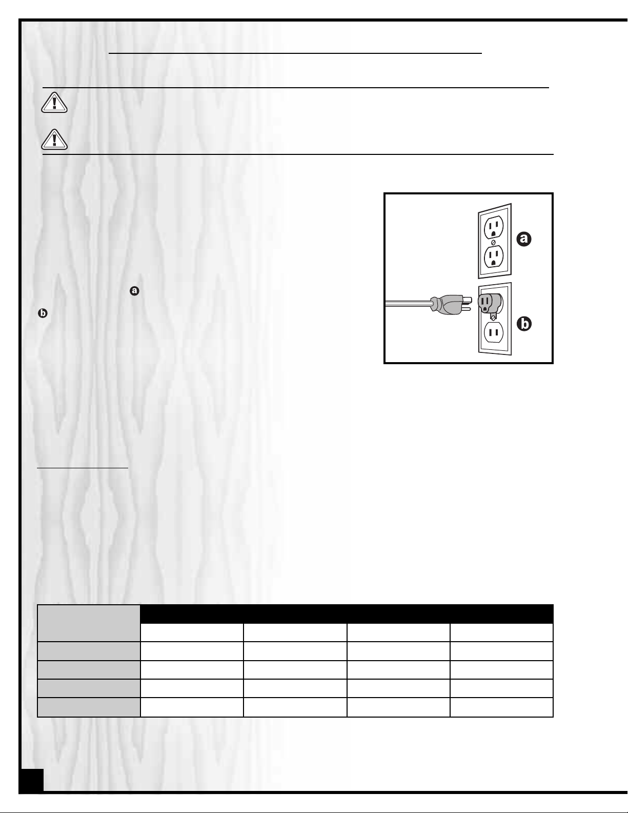
GROUNDING: In the event of an electrical malfunction or short circuit,
grounding reduces the risk of electric shock to. The motor of this
machine is wired for 110V single phase operation and is equipped
with a 3-conductor cord and a 3-prong grounded plug to fit a grounded type receptacle, . Do not remove the 3rd prong (grounding pin)
to make it fit into an old 2-hole wall socket. If an adaptor plug is used,
, it must be attached to the metal screw of the receptacle.
Note: The use of an adaptor plug is illegal in some areas. Check
your local codes.
DO NOT MODIFY THE PLUG PROVIDED.
If it will not fit your receptacle, have the proper receptacle installed by a qualified electrician.
CHECK with a qualified electrician or service person if you do not completely understand these grounding instructions, or if you are not sure the tool is properly grounded.
EXTENSION CORDS:
USE ONLY 3-WIRE EXTENSION CORDS THAT HAVE 3-PRONG GROUNDING PLUGS AND 3-POLE RECEPTACLES THAT ACCEPT
THE TOOLS’ PLUG. REPAIR OR REPLACE A DAMAGED OR WORN POWER CORD OR PLUG IMMEDIATELY.
If you find it necessary to use an extension cord with your machine make sure the cord rating is suitable for the
amperage listed on the motor I.D. plate. An undersized cord will cause a drop in line voltage resulting in loss of
power and overheating. The accompanying chart shows the correct size extension cord to be used based on cord
length and motor I.D. plate amp rating. If in doubt, use the next heavier gauge. The smaller the gauge number, the
heavier the cord.
AMPERES
(AMPS)
25 FEET 50 FEET 100 FEET 150 FEET
EXT E NS I O N C OR D LEN G TH
<6 18 16 16 14
6 TO 10 18 16 14 12
10 TO 12 16 16 14 12
12 TO 16 14 12 NA NA
NA = Not Available
4
Page 5
12” BANDSAW
90-060
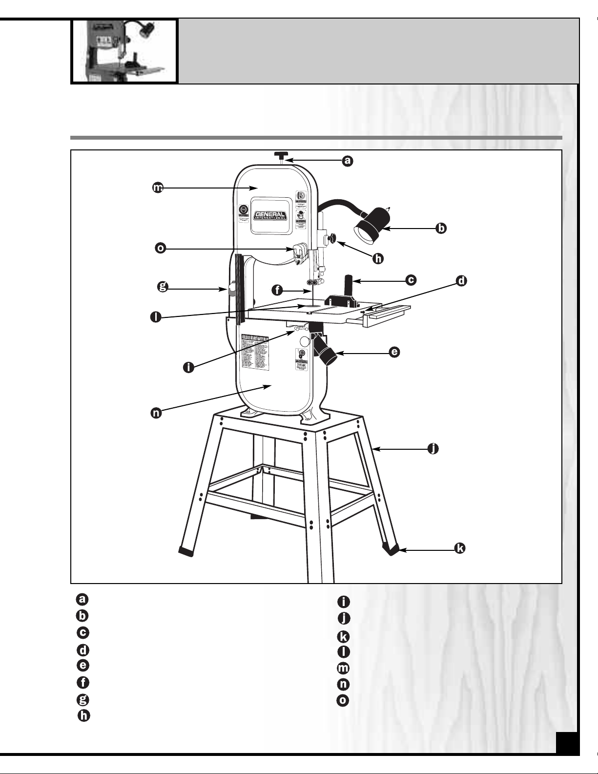
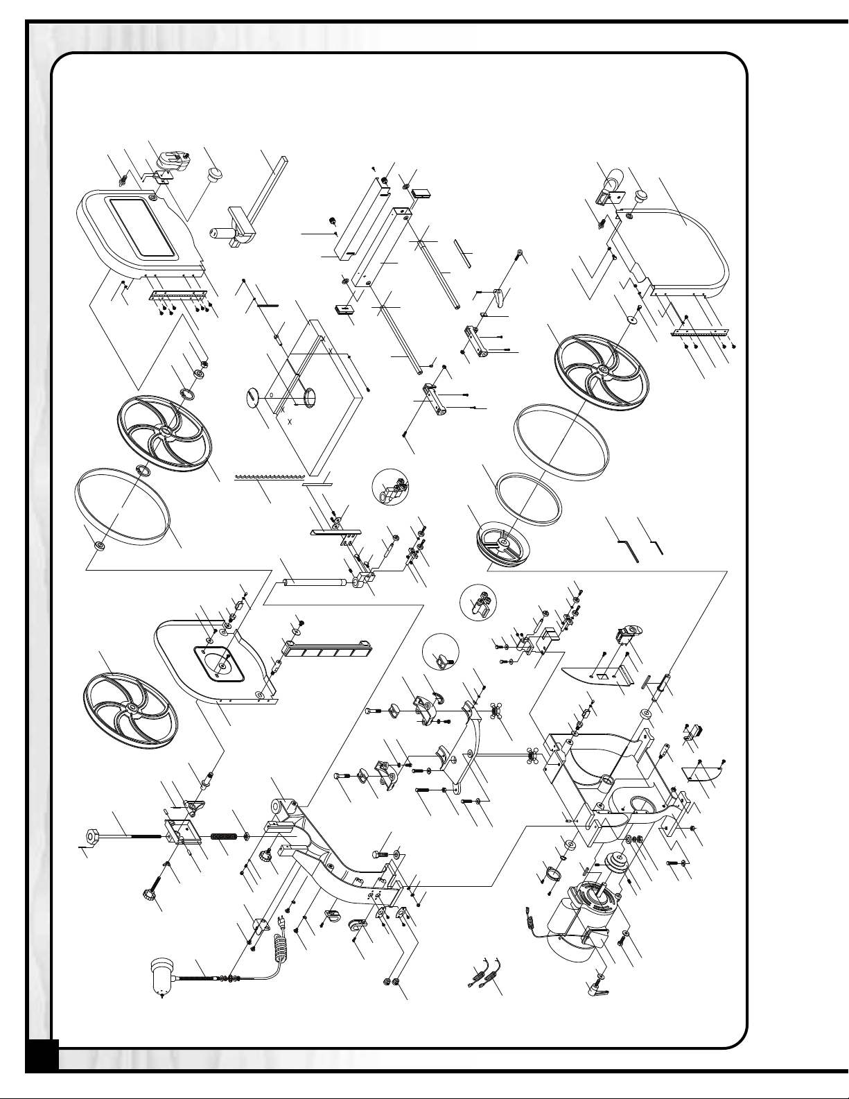
IDENTIFICATION OF MAIN PARTS AND COMPONENTS
BLADE TENSION KNOB
WORK LIGHT
MITER GAUGE
TABLE ALIGNING PIN
DUST PORT
BLADE
ON/OFF SWITCH
UPPER BLADE GUIDE LOCK KNOB
TABLE TILT LOCK KNOB
STAND
FOOT PAD
TABLE INSERT
UPPER WHEEL COVER DOOR
LOWER WHEEL COVER DOOR
LASER LINE MARKER
5
Page 6
UNPACKING & SET UP
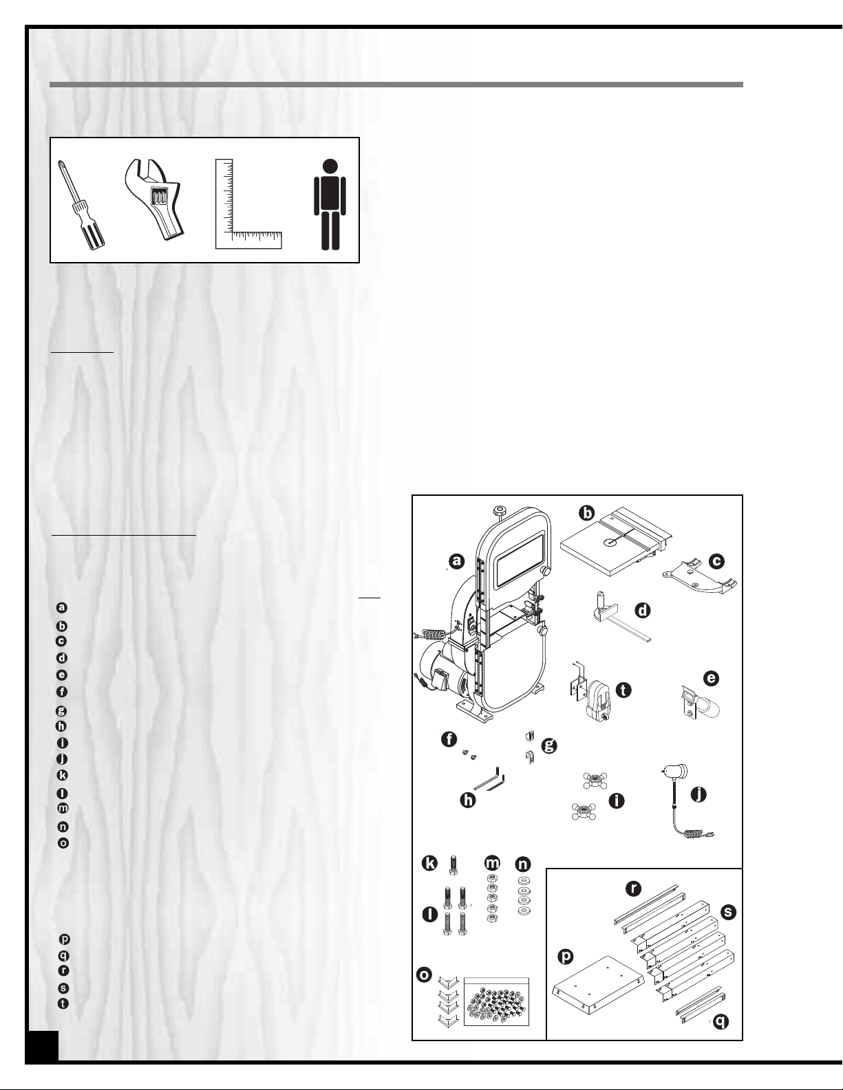
ADDITIONAL TOOLS NEEDED
• Philips screwdriver
• Adjustable wrench
• Straightedge
• Extra person for help with lifting
UNPACKING
Carefully unpack and remove the bandsaw and its components from the box and check for missing or damaged
items as per the list of contents below.
Note: Please report any damaged or missing items to your General International distributor immediately.
LIST OF CONTENTS
Once the parts have been removed from the
packaging, you should have the following items:
BANDSAW W/MOTOR . . . . . . . . . . . . . . . . . . . . . . . . .1
TABLE W/EXTENSION WING . . . . . . . . . . . . . . . . . . . . .1
TRUNNION SUPPORT BRACKET . . . . . . . . . . . . . . . . . .1
MITER GAUGE . . . . . . . . . . . . . . . . . . . . . . . . . . . . . . .1
DUST PORT . . . . . . . . . . . . . . . . . . . . . . . . . . . . . . . . . .1
SCREWS . . . . . . . . . . . . . . . . . . . . . . . . . . . . . . . .2
POWER CORD HOOKS . . . . . . . . . . . . . . . . . . . . . . . .2
ALLEN KEY . . . . . . . . . . . . . . . . . . . . . . . . . . . . . . . .2
TABLE TILT LOCK KNOBS . . . . . . . . . . . . . . . . . . . . . . .2
WORK LIGHT . . . . . . . . . . . . . . . . . . . . . . . . . . . . . . . .1
BOLT 5/16” X 1” . . . . . . . . . . . . . . . . . . . . . . . . . . . . . .1
BOLT 5/16” X 1 1/4” . . . . . . . . . . . . . . . . . . . . . . . . . . .4
HEX NUT 5/16” . . . . . . . . . . . . . . . . . . . . . . . . . . . . . . .5
LARGE WASHER . . . . . . . . . . . . . . . . . . . . . . . . . . . . . .4
HARDWARE BAG . . . . . . . . . . . . . . . . . . . . . . . . . . . . .1
CARRIAGE BOLT . . . . . . . . . . . . . . . . . .3 2
HEX. NUT . . . . . . . . . . . . . . . . . . . . . . . .3 2
WASHER . . . . . . . . . . . . . . . . . . . . . . . .3 2
FOOT PAD . . . . . . . . . . . . . . . . . . . . . . .4
Qty
TOP PLATE . . . . . . . . . . . . . . . . . . . . . . . . . . . . . . . . . . .1
SHORT LOWER BRACKET . . . . . . . . . . . . . . . . . . . . . . .2
LONG LOWER BRACKET . . . . . . . . . . . . . . . . . . . . . . .2
LEG . . . . . . . . . . . . . . . . . . . . . . . . . . . . . . . . . . . . . . . .4
LASER LINE MARKER (WITH HARDWARE) . . . . . . . . . .1
6
Page 7
ASSEMBLY INSTRUCTIONS
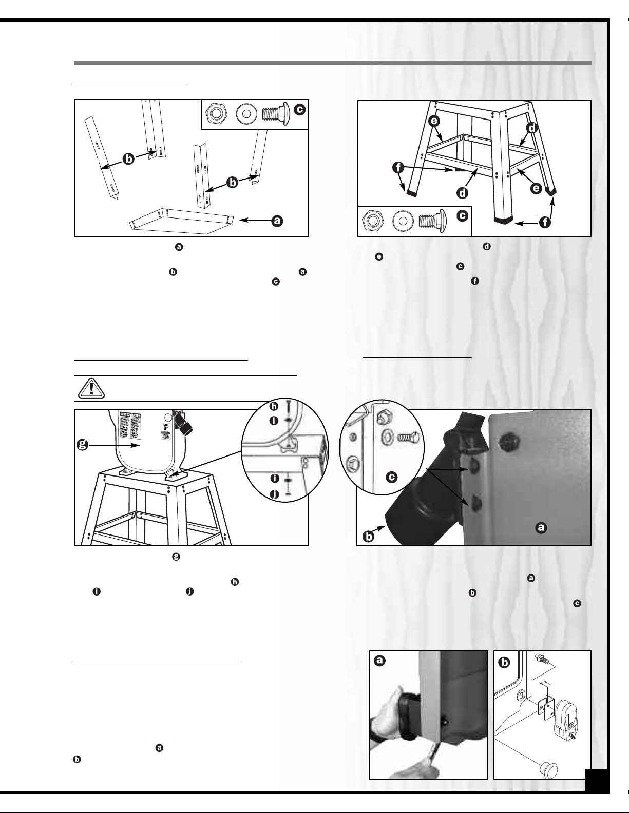
ASSEMBLING THE STAND
Lay the top plate upside down on a flat sur-
1.
face.
2. Attach the 4 legs to the outside of top plate
using 4 carriage bolts, washers, and nuts
Note: Do not tighten hex nuts until all fasteners are
attached.
ATTACHING THE BANDSAW TO STAND
The bandsaw is heavy. The help of an assistant will be needed to lift the bandsaw.
.
3. Attach 2 long brackets and 2 short brackets
to the inside for the legs, using carriage bolts,
washers, and nuts .
4. Place the foot pads on the bottom of each
leg.
5. Place the stand on a flat surface to square it up
and finally tighten all the nuts.
ATTACHING DUST PORT
The dust port has a 2-1/2” opening
connection to a dust collector (not included).
to accommodate
1. Lift the saw body with the help of an assistant
and place it on the stand.
2. Using 4 long hex head bolts , 8 flat washers
, and 4 hex nuts , secure the bandsaw to
the stand and tighten all mounting bolts.
INSTALLING THE LASER LINE MARKER
The door knob and its threaded pin are used as the
fasteners to secure the laser line marker mounting
bracket to the door.
To install the laser line marker on the door, first remove
the door knob and its pin. Then re-install the knob with
its pin through the hole in the laser line markers’
mounting bracket in the order of assembly shown
.
1. Remove the bolts and washers from the dust
port.
2. Open the lower wheel cover door
3. Attach the dust port to the edge of the door
using the same hex head bolts and washers .
4. Tighten the bolts and close the door.
.
7
Page 8
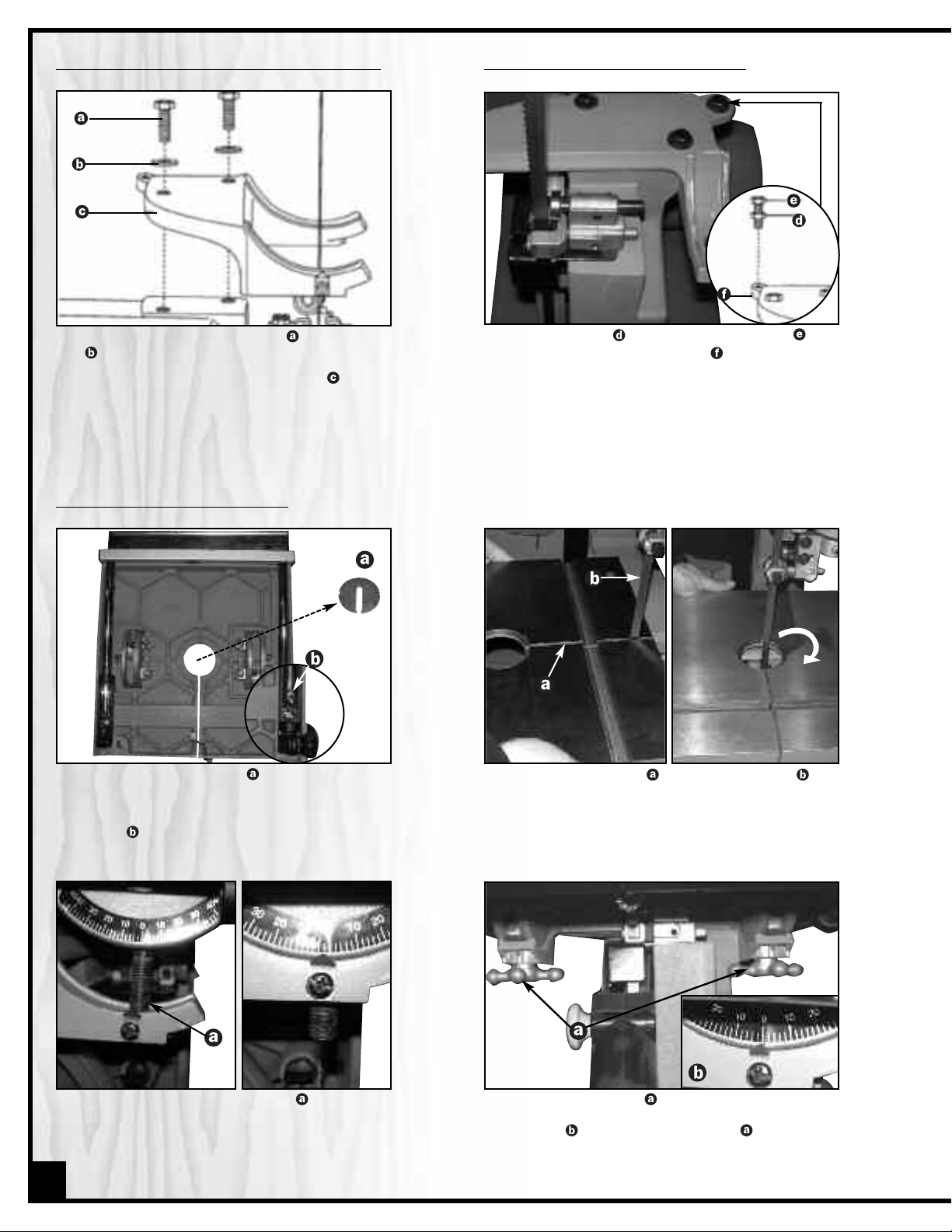
MOUNTING THE TRUNNION SUPPORT BRACKET
INSTALLING 90° TABLE TILT STOP BOLT
1. Remove the 2 hex head bolts and washers
, located on the lower band saw housing.
2. Place the trunnion support bracket on the
saw body, aligning the mounting holes.
3. Place the washers on the hex head bolts, and
insert into the threaded holes, through the
bracket and saw body. Tighten.
INSTALLING THE BANDSAW TABLE
1. Remove the table insert from the table.
2. The extension table must be removed before
placing table onto saw. Unscrew the stopscrew on the rear extension table guide bar
and pull the extension table off of the main
table.
1. Thread the nut onto the table stop bolt and
screw bolt into the rear tab on the trunnion
support bracket. Tighten the nut down onto the
bracket tab.
2. After installing the table, the 90° stop bolt can be
adjusted up or down as needed to “stop” the
table at 90° to the blade.
90° CW
3. Guide the table slot over the saw blade and
rotate 90° clockwise so the slot is perpendicular
to the blade.
4. Slip the 2 table tilt trunnion bolts through the
holes in the trunnion brackets (front & rear) as
shown.
8
5. Place a lock knob on each bolt and adjust
the table, aligning the zero scale mark to the
pointer , then tighten the knobs .
Page 9

bottom
view
MITER GAUGE
6. Re-install the table insert .
7. Insert the table aligning pin in the hole at
the side of the table.
8. Re-install the extension table and re-attach the
stop-screw
.
INSTALLING POWER CORD STORAGE BRACKETS
Attach the power cord brackets to the rear of
the saw, as shown using the 2 Phillips head screws
.
To prevent damage, stow the cord by wrapping it onto the brackets whenever the saw is not
in use.
REMOVING & INSTALLING THE BLADE
Store the miter gauge on the supplied bracket on the
stand as shown.
ATTACHING THE WORK LIGHT
Remove 4 phillips screws from machine body. Install
the work light and the power cord to the machine
body by using 4 phillips screws and tighten.
The worklight uses a standard 110V household lightbulb, 60 Watts - Not Included.
Before replacing or adjusting the blade, make sure the switch is in the “OFF” position and that the power cord is unplugged.
Note: Extension table must be removed when removing/installing the blade. See Step 2 & 8 in INSTALL THE BANDSAW TABLE, pg. 8 & 9.
1. To remove blade, release blade tension by turning
the blade tension knob counter-clockwise until
it stops.
2. Remove the table insert and table aligning pin.
3. Open upper and lower wheel cover doors.
4. Loosen the 2 Phillips screws and remove the
upper blade guard .
5.
Remove the blade from the upper and lower
blade guides. Carefully pull the blade from the
side slot and from the wheels
.
6. Swing the left side of the blade toward you, turning
the blade so it will fit through the slot in the table
and remove.
9
Page 10

Make sure the blade is in the center of the table insert slot before operating.
To install a blade, repeat the previous steps (Pg. 9) in
reverse order, making sure that the blade is installed with
the teeth pointing forward and down as shown.
With the blade installed, re-attach the extension table and
then proceed to “BLADE TENSION ADJUSTMENTS” and
“BLADE TRACKING ADJUSTMENTS” in the “RECOMMENDED
ADJUSTMENTS” section of this manual, Pg. 11.
RECOMMENDED ADJUSTMENTS
Before making any adjustments, make sure that the switch is in the “OFF” position and that the power cord is
unplugged.
TILTING THE TABLE
Proper installation
Improper installation
1. Loosen both table lock knobs underneath the table.
2. Manually tilt the table to the desired angle on the
scale under the table.
3. Tighten the knobs to secure the table at the desired
angle.
ADJUSTING THE 90° TABLE STOP
1. Loosen both table lock knobs underneath the table
and tilt the table to the right.
2. Loosen the nut on the table stop bolt and lower
the stop bolt as far as possible.
3. Place a combination square on the table against
the saw blade.
4. Adjust the tilt of the table left or right until it is 90° to the
blade. Make sure there is no space between the square
and the blade. Tighten the lock knobs .
5. Adjust the table stop bolt up until it touches the
underside of the table.
6. Loosen the lock knobs and verify that the table is resting on the stop bolt .
7 . Check the square to make sure the table is still
90° to the blade. If not, re-adjust the stop bolt as
needed.
8 . When the adjustment is accurate at 90°, tighten down
the nut on the stop bolt , tighten the table lock knobs
and align the pointer to the 0° mark on the angle
indicator scale
.
10
Page 11

BLADE TENSION ADJUSTMENTS
Before making blade tension adjustments, make sure that the switch is in the “OFF” position and that the power
cord is unplugged.
The gauge on the bracket at the rear of the upper
wheel housing indicates the proper tension for the various
blade widths.
1. Set the blade tension gauge to correspond with the
width of the blade in use.
2. Turn the blade tension knob clockwise, raising the
upper wheel to tighten the blade. Turn the knob counter-clockwise to lower the upper wheel, loosening the
blade.
Note: Changes in blade width and the type of material
being cut will have an effect on the blade tension. Too
much or too little tension could break the blade. When
the band saw is not in use, loosen the tension on the
blade, to prolong blade life.
BLADE TRACKING ADJUSTMENTS
Note: The blade must be tensioned properly before
adjusting the tracking.
1. Open the upper wheel cover door and move the
blade guides and support bearings away from
the blade, if necessary. See page 12-13 for bearing
and guide adjustment.
2. Rotate the wheel slowly forward by hand, and check
the position of the blade on the wheel. The blade
should remain centered on the wheel as it turns.
A) If the blade moves toward the front of the wheel, turn
the tracking knob on the back of the band saw
clockwise. This tilts the top of the wheel to the back and
moves the blade toward the center.
B) If the blade moves toward the back edge, turn the
tracking knob counter- clockwise, moving the blade
toward the center.
Note: Turn the tracking knob in 1/2 turn increments,
re-check and adjust again as needed.
CL
Back View
Turn CW
if blade
moves
to front
Turn
CCW if
blade
moves
to back
11
Page 12

ADJUSTING THE BLADE GUARD FOR DEPTH OF CUT
1. Loosen the lock knob and manually move the blade
guard assembly up or down to set the guard to
1/8” - 1/4” above the workpiece.
2. Re-tighten the lock knob, before turning on the saw.
3. Adjust the height of the blade guard to suit the thickness of the workpiece .
UPPER BLADE GUIDE
To avoid injury, make sure that the switch is in the “OFF” position and that the power cord is unplugged.
Note: In the drawing below, the blade guard has been removed for clarity of illustration. To avoid injury, never operate
the bandsaw without all guards in place and in proper working order.
Note: Make sure the blade is tensioned and tracking properly. Adjust the blade guide and support bearings after each
blade tension and tracking adjustment. Whenever the upper blade guide and support bearings are adjusted, the lower
guide and support bearings should also be adjusted.
1. Loosen the set screws and move the roller bearing
as close to the blade as possible without pinching it.
2. Using a feeler gauge, make sure the space between
each bearing and the blade measures 0.02” (the thickness of a dollar bill).
3. Re-tighten the set screws and loosen the side thumb
screw by turning counter-clockwise.
4. Move the blade guide bracket shaft in or out until the
roller bearings are at least 1/32” behind the blade
teeth.
5. The roller bearing must remain behind the blade
teeth during operation to prevent damage to the
blade. Tighten the thumb screw
.
POSITIONING THE UPPER SUPPORT BEARING
Note: The blade support bearing prevents the blade
from moving back too far and damaging the saw teeth
setting.
1. To re-position the support bearing, loosen the thumb
screw .
2. Move the support bearing shaft in or out, until the
bearing is 1/64” behind the blade.
”
3. Tighten the thumb screw .
12
Page 13

LOWER BLADE GUIDES
Note: The lower blade guides and support bearings
should always be adjusted after the blade is tensioned,
tracking is adjusted, and the upper blade guides and
upper support bearings are properly adjusted.
1. Loosen both front hex socket screws with a hex
wrench and move the bearings as close to the sides
of the blade as possible without pinching it.
2. Using the feeler gauge, measure the spaces between
the guide and the blade. Adjust to 0.02”.
3. Tighten the hex screws and loosen the side hex socket screw . Move the guide support bracket in or out
until the guides are at least 1/32” behind the saw teeth.
Tighten the screw.
LOWER SUPPORT BEARING
1. Loosen the bearing hex socket screw with the hex
wrench.
2. Move the blade support bearing shaft in or out until
the support bearing is 1/64” behind the saw blade.
3. Tighten the bearing hex socket screw .
LASER LINE MARKER
This model 90-060 is equipped with a laser line marker, located on the front right side hand of the upper wheel cover door
, allowing you to easily mark a straight cut line on your
workpiece.
Note: Requires two AAA batteries (not included). Slide upwards and remove the battery cover .
Align the laser beam on the blade as follows:
Move ON/OFF switch up to turn the laser marker
1.
on.
Move the beam adjustment knob in any direction
2.
until the beam is aligned with the blade .
PULLEY ALIGNMENT
Note: The pulley alignment has been pre-set and verified
at the factory and should not need re-adjustment. If
adjustment is needed or the belt needs replacing:
1. Place a straight edge in the front groove of both pulleys, behind the blade wheel.
2. Turn the set screw in the side of the motor pulley to
loosen the pulley on the shaft.
ON / OFF SWITCH
ON
CLOSE UP
OFF
BEAM
ADJUSTMENT KNOB
3. Adjust the pulley in or out on the shaft to align the
edges of the two pulleys.
4. When aligned, re-tighten the set screw on the side of the
motor pulley.
13
Page 14
OPERATING INSTRUCTIONS
ON/OFF POWER SWITCH
The bandsaw is equipped with a rocker type ON/OFF switch, located at the left, that is equipped with a lock-out key.
To prevent unwanted or unauthorized start-up or usage remove the lock-out key and store it in a safe place.
To start the bandsaw, insert the lock-out key and pull up the switch . To stop the bandsaw, push down on the
power switch . When the saw comes to a complete stop, remove the lock-out key by gently pulling it outward.
POWER ON
USING THE TABLE EXTENSION
When working with wider or longer work pieces that may need additional support the table extension can be pulled out and locked in place to
provide wider work surface.
1. Loosen the cam lock lever at the front of the table.
2. Pull out and slide the table extension to the required position.
3. Lock down the cam lock lever to secure the table extension in
place.
USING THE RIP FENCE
For more precise straight line cuts there is a retractable rip fence attachment on the end of the table extension.
1. Loosen the 2 lock knobs on the end of the extension table.
2. Raise the rip fence and while holding it in place above the table, retighten the 2 lock knobs.
3. Adjust the positioning of the table extension so that the distance
from the inside face of the rip fence to the blade matches the
required width of cut. Make sure to lock the table extension in place
before starting to cut against the rip fence.
POWER OFF LOCK-OUT KEY
(PREVENTS START-UP WHEN REMOVED)
CUTTING CURVES
• When cutting curves, carefully turn the workpiece so the blade follows without twisting, If the curve is so sharp that
you repeatedly back up and cut new kerf, use a narrower blade, or a blade with more set (teeth further apart).
When a blade has more set, the workpiece turns easier but the cut is rougher.
• When changing a cut, do not withdraw the workpiece from the blade. The blade may get drawn off the wheels.
• To change a cut, turn the workpiece and cut your way out through the waste material area.
• When cutting long curves, make relief cuts as you go along.
14
Page 15
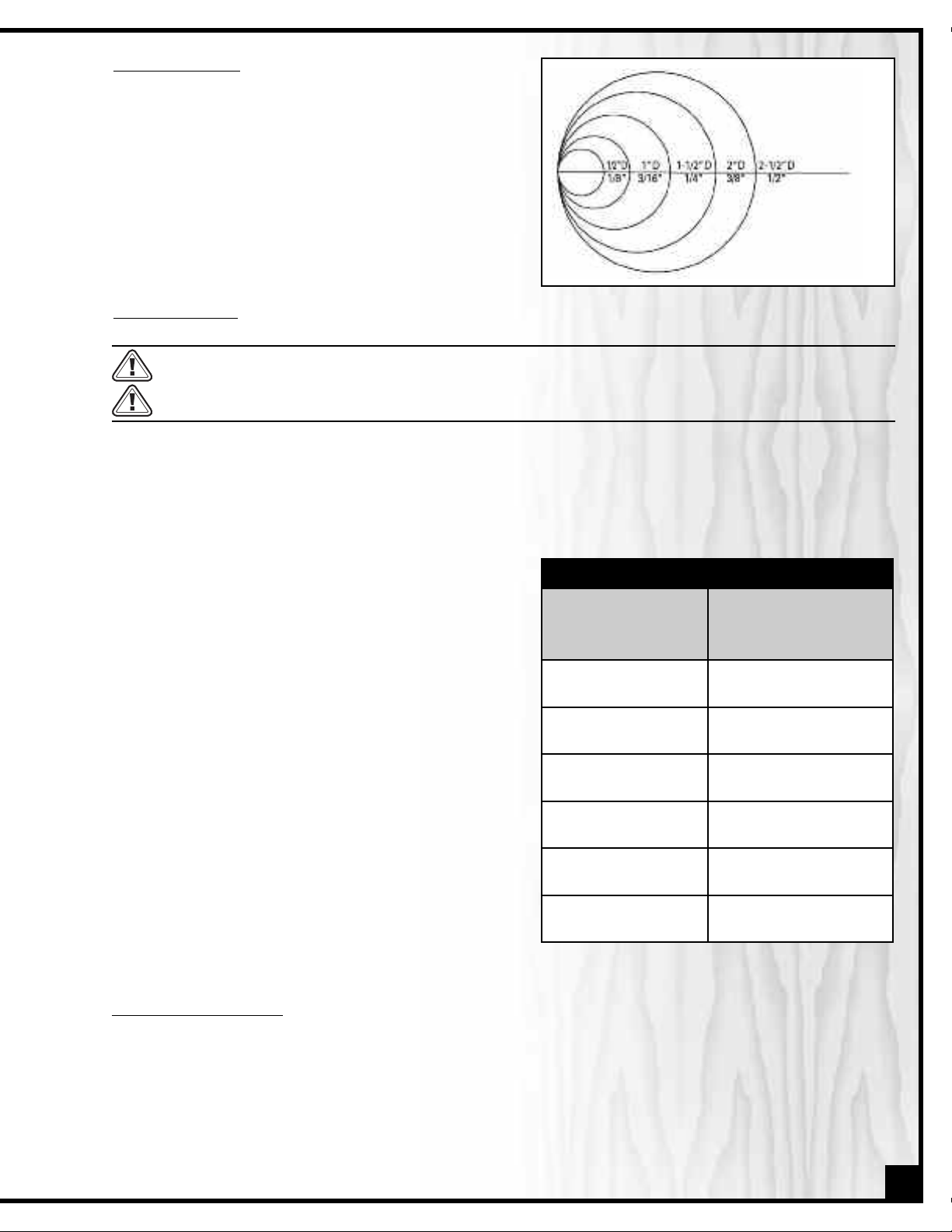
CUTTING CIRCLES
1. Adjust the blade guard assembly to 1/8” above the
workpiece.
2. Use both hands while feeding the work into the blade.
Hold the workpiece firmly against the table. Use gentle
pressure. Do not force the work. Allow the blade to cut.
MIN. CIRCLE
DIAM.
3. The smallest diameter circle that can be cut is determined by the width of the blade. For example, a 1/4”
wide blade will cut a minimum diameter of approximately 1-1/2”.
BLADE WIDTH
BLADE SELECTION
Blade teeth are sharp. Use care when handling a saw blade.
Do not cut ferrous metals with this bandsaw.
There are a variety of different types of bandsaw blades on the market to suit various cutting applications. The accompanying “Blade Selection” chart is provided as a general reference tool; your results may vary based on usage, experience and personal preference. Ask your local tool dealer for suggestions for 80” bandsaw blades in 1/8” to 1/2”
widths, based on what is available in your area.
Some general guideline to consider when choosing bandsaw blades:
• Wider blades with coarse teeth are best suited to cutting
straight lines, re-sawing and for sweeping curves,but will
not turn tight corners. They will cut quickly and aggressively but do have a tendency to bind (or get stuck in
the cut) if turned to sharply.
B L AD E S E L E C TI O N
OPERATION RECOMMENDED BLADE
WIDTH (INCHES)
CROSS CUTTING 1/4, 3/8, 1/2
• Narrower, thinner blades with finer teeth will cut more
slowly but can turn much tighter corners for cutting
more intricate work.
Common causes of blade breakage:
• Poor guide bearing alignment and adjustment.
• Forcing or twisting a wide blade around a short radius.
• Feeding the workpiece too quickly.
• Dull teeth.
• Too much blade tension.
•Setting blade guard assembly too high above the workpiece.
•Lumpy or improperly finished braze or weld on the
blade.
• Continuous running of blade when not cutting.
MITERING 1/4, 3/8, 1/2
BEVELING 1/4, 3/8, 1/2
COMPOUND CUTTING 1/4, 3/8, 1/2
CIRCLE CUTTING SEE “CUTTING CIRCLES”
CURVE CUTTING 1/8, 1/4
SELECTING BLADE SPEED
This bandsaw is equipped with 2 speed settings: High - 2710 Feet Per Minute (FPM) and Low- 1580 FPM, allowing you to
achieve better results by selecting a more appropriate blade speed based on the cutting operation being performed.
Some general guidelines to consider for selecting blade speed:
Thick Material = Slower Speed
Harder or Denser Material = Slower Speed
Blades with Fine Tooth Pitch = Slower Speed
Thin Material = Faster Speed
Soft Material = Faster Speed
Blades with Few Teeth PI = Faster Speed
15
Page 16

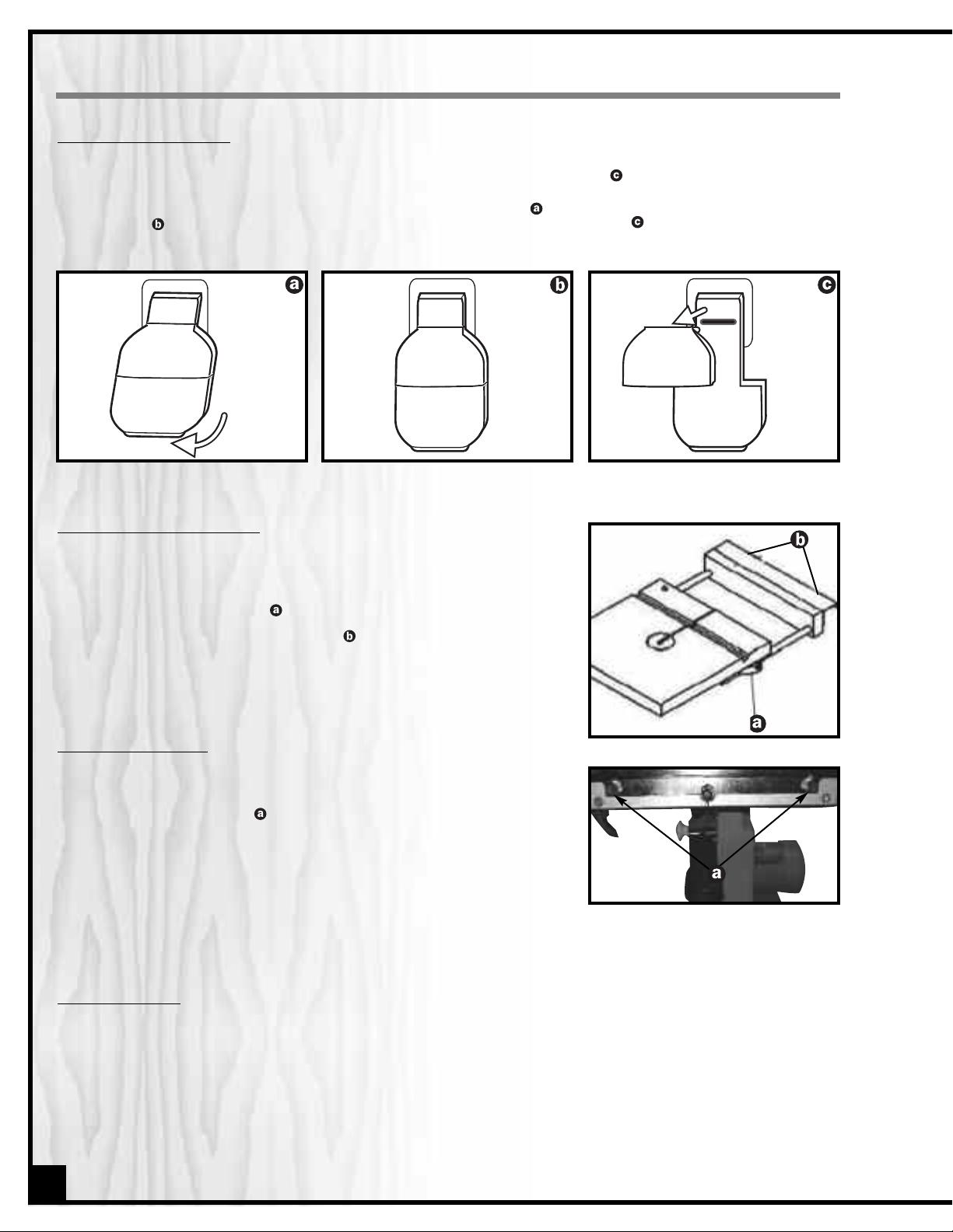
CHANGING SPEED SETTING
NEVER make adjustments with the machine running.
1. Loosen the belt tension by turning the tension lock handle
the rear of the saw.
2. Open the lower wheel cover and reposition the V-belt .
A) Changing the speed from 1580 to 2710 FPM:
Remove the belt from the band saw pulley first, and
reposition in the saw pulley groove . Next, remove the belt
from the motor pulley and reposition in the motor pulley
groove .
B) Changing the speed from 2710 to 1580 FPM:
Remove the belt from the motor pulley first, and reposition in the motor pulley groove . Remove the belt from the
saw pulley and reposition in the saw pulley groove .
3. Tighten the belt tension by turning the tension lock handle .
Note: After readjusting belt position and belt tension, check
and readjust the settings for the blade tension and tracking,
guides and bearings (See ADJUSTMENT section on page 11).
at
MOTOR
MAINTENANCE & LUBRICATION
Before performing any maintenance, cleaning, adjusting, or lubricating your band saw, make sure that the switch
is in the “OFF” position and that the power cord is unplugged.
To avoid fire or toxic reaction, never use gasoline, naphtha, acetone, lacquer thinner or similar highly volatile solvents to clean the band saw.
To avoid eye injury from blowing debris, wear safety goggles when blowing out sawdust.
Keep your band saw clean. Sawdust will accumulate under the table, base and in the wheel housings. This could
cause difficulty in the movement of the table when setting up a band saw cut. Frequently blow out or vacuum up the
sawdust.
Do not allow dirt, pitch or gum to build up on the table, the guide, or support bearings. Clean as needed with gum
and pitch remover.
Note: Do not immerse the bearings in the gum and pitch remover. Put a thin coat of paste wax on the table so
that the wood slides easily while cutting.
16
Page 17

TO INSTALL A NEW BELT
1. Open the lower wheel door and loosen the blade tension by turning the blade tension lock knob .
2. Remove the blade from the lower blade wheel.
3. Loosen and remove the hex head bolt and flange
on the lower blade wheel.
4. Remove the lower blade wheel.
5. Turn the belt tension handle on the rear of the saw
housing to loosen the v-belt tension.
6. Remove the v-belt .
7. Check the alignment of the two pulleys.
8. If the edges of the two pulleys are not aligned, see: PULLEY ALIGNMENT on Page 13.
9. Place the new v-belt on the saw pulley and the motor
pulley. See CHANGING SPEED SETTING on Page 16 for
proper belt placement.
10. When positioned properly, tighten the v-belt tension by
turning the tension lock handle.
Note: The pulley belt is properly tensioned when there is
1/2” deflection if pressed in the center between the pulleys.
11. Replace the blade wheel. Push the wheel firmly until it is touching the saw pulley. Replace and tighten the flange
and nut.
12. Reinstall the blade (See INSTALL THE BLADE on page 9).
13. Adjust the blade tension, tracking, and the upper and lower blade guides and bearings before operating the bandsaw. (See pages 11-13)
BLADE WHEEL TIRES
Pitch and sawdust that build up on the tires should be removed with a stiff brush or scraped off with a piece of wood.
NOTE: To avoid damaging the tires do not use a sharp knife or any kind of solvent. When the tires become worn
they should be replaced. When replacing the tires, stretch them around the wheels but do not glue then on.
MOTOR
Frequently blow or vacuum out any sawdust from the motor. Follow lubrication instruction on the motor label.
LUBRICATION
All of the bearings are sealed and permanently lubricated. They require no further lubrication.
Never put lubricants on the blade while it is spinning.
17
Page 18
121
117
111
116
109
110
108
82
108
113
107
99
99
83
115
120
119
112
123
128
80
89
87
86
126
85
114
84
99
127
96
107
94
128
100
101
95
91
92
90
97
99
98
93
88
122
63
57
66
77
78
50
4
49
48
47
36
52
64
79
1
54
65
6
43
65
34
71
53
32
46
31
33
35
26
33
45
37
5
65
15
38
81
44
70
39
42
41
65
29
30
28
74
25
24
55
27
56
52
51
124
22
21
23
18
19
20
8
16
17
11
125
65
38
14
68
60
62
61
42
3
40
35
59
67
81
44
58
2
15
42
7
9
9-1
10
63
42
14
69
58
70
39
65
12
13
129-1
134
131
135
130
137
140
136
141
142
139
102
104
105
138
133
106
86
143
144
147
148
72
72
118
73
73
76
75
146
145
65
65
149
150
130-1
130-2
129-4
129-2
129-3
129-5
103
129
151
123
152
153
154
18
Page 19

PARTS LIST - 90-060
PART N0. DESCRIPTION SPECIFICATION QTY
90050-01 1
90050-02 1
90050-03 1
90050-04 1
90050-05 1
90050-06 1
90050-07 1
90050-08 1
90050-09 1
90050-09-1 3 x 30 1
90050-10 1
90050-11 312L 1
90050-12 (V TYPE) 1
90050-13 1
90050-14 2
90050-15 2
90050-16 1
90050-17 1
90050-18 5/16 x 2 1
90050-19 5/16 1
90050-20 2
90050-21 5/16 x 5/16 1
90050-22 1
90050-23 1/4 1
90050-24 5/16 x 1-1/4 1
90050-25 2
90050-26 1
90050-27 2
90050-28 SJT18 x 3C 1
90050-29 SJT18 x 3C 1
90050-30 6N-4 2
90050-31 1
90050-32 S-15 1
90050-33 6202ZZ 2
90050-34 1/4 x 16mm 2
90050-35 3/8 2
90050-36 3" 1
90050-37 1
90050-38 3/8 2
90050-39 2
90050-40 ABS 1
90050-41 4P J9305 1
90050-42 626ZZ 6
90050-43 1
90050-44 2
90050-45 5 x 5 x 54 1
90050-46 5 x 5 x 32.5 1
90050-47 1
90050-48 3/8" x 23 x 2T 1
BASE FRAME
UPPER ARM
REAR UPPER COVER
MOTOR ASSEMBLY W/CORD
FRAME ARM COVER, UPPER
FRAME ARM COVER, LOWER
POST MOUNTING BLOCK
SLIDING BRACKET
UPPER WHEEL SHAFT HINGE
PIN
UPPER WHEEL SHAFT
TENSION ADJUST ASSY W/KNOB
GUIDE POST
BLADE GUARD
BEARING SHAFT
"Y" TYPE BEARING BLOCK
ADJUST SPRING
SQUARE NUT
TRACKING ADJUSTMENT KNOB
BUTTERFLY NUT
PIN
CAP SCREW
SPRING
STEEL BALL
LOCK KNOB
POWER CORD STORAGE BRACKET
LOWER BLADE GUARD
PLATE
POWER CORD W/PLUG
POWER CORD W/INSERT PLUG
STRAIN RELIEF
BEARING COVER
C RING
BEARING
PIN
PIN FIXTURE BOLT
MOTOR PULLEY
LOWER WHEEL SHAFT
HEX. FIXTURE BOLT
DOOR RETAINER CLIP
INNER GUARD
SAFETY SWITCH
BEARING
WHEEL BRUSH ASSY.
STEEL WASHER
KEY
FLAT KEY
KNOB
FLAT WASHER
19
Page 20

PARTS LIST - 90-060
PART N0. DESCRIPTION SPECIFICATION QTY
20
90050-49 3/8" x 1-1/2" 1
90050-50 3/8" x 19 x 2T 1
90050-51 3/4" x 2-1/2" 1
90050-52 3/4" x 46 x 3T 2
90050-53 3/4" 1
90050-54 3/8" 1
90050-55 5mm 2
90050-56 2
90050-57 3/16" x 1/4" 2
90050-58 3/16" x 14 X1T 4
90050-59 5/16"-23 x 2.0mm 2
90050-60 1
90050-61 1/4" x 3/4" 2
90050-62 1/4"x16x2T 2
90050-63 M6 x 10x1T 4
90050-64 M6 x 16 2
90050-65 3/16" x 3/8" 17
90050-66 3/16" x 3/8" 2
90050-67 3/16" x 3/8" 2
90050-68 1/4" x 1/4" 2
90050-69 1/4" x 1/2" 1
90050-70 3/16" x 1/4" 2
90050-71 3/4" 1
90050-72 M6 4
90050-73 M6 x 20L 4
90050-74 3/16" x 1/2" 2
90050-75 M6 x 16L 1
90050-76 M6 x 10L 1
90050-77 5/16" x 1-1/4" 4
90050-78 5/16" x 23 4
90050-79 5/16" 4
90050-80 1
90050-81 3/16" 2
90050-82 1
90050-83 1
90050-84 1
90050-85 80" x 3 / 8" x 0.5mm x 6T 1
90050-86 6002ZZ 2
90050-87 1/2" 1
90050-88 2
90050-89 2
90050-90 M10 x 40 2
90050-91 5/16" 6
90050-92 1/4" x 5/8" 6
90050-93 1
90050-94 M10 2
90050-95 5/16" x 1-1/4" 2
90050-96 5/16" x 18x2T 2
90050-97 1
HEX. SCREW
FLAT WASHER
HEX HEAD BOLT
FLAT WASHER
HEX. NUT
NYLON NUT
SPROCKET WASHER
COPPER WASHER
PHILLIPS HEAD METAL SCREW
STEEL WASHER
STEEL WASHER
LOWER SUPPORT BRACKET
HEX. HEAD BOLT
FLAT WASHER
FLAT WASHER
SET SCREW
PHILLIPS HEAD METAL SCREW
PHILLIPS HEAD SCREW
HEADLESS CROSS SCREW
SET SCREW
SET SCREW
PHILLIPS HEAD SCREW
LOCK WASHER
NUT
CAP SCREW
PHILLIPS HEAD METAL SCREW
THUMB SCREW
THUMB SCREW
HEX HEAD BOLT
FLAT WASHER
NUT
DUST PORT
LOCK WASHER
LOWER DOOR HINGE
LOWER WHEEL WASHER
UPPER DOOR HINGE
BLADE
BEARING
HEX. NUT
TRUNNION
TRUNNION CLAMPING SHOE
HEX HEAD BOLT
LOCK WASHER
HEX HEAD BOLT
SCALE
TABLE TILT LOCK KNOB
HEX HEAD BOLT
FLAT WASHER
POINTER
Page 21

PARTS LIST - 90-060
PART N0. DESCRIPTION SPECIFICATION QTY
90050-98 3/16" x 3/8" 1
90050-99 3/16" 17
90050-100 5/16" x 1" 1
90050-101 5/16" 1
90050-102 1
90050-103 1
90050-104 1
90050-105 1
90050-106 1
90050-107 3/16" 12
90050-108 3/16" x 1/4" 12
90050-109 1/4" x 5/8" 1
90050-110 3/16" x 3/8" 4
90050-111 1
90050-112 1
90050-113 1
90050-114 1
90050-115 1
90050-116 2
90050-117 3 mm 1
90050-118 5 mm 1
90050-119 2
90050-120 1/4" x 3/8" 2
90050-121 1
90050-122 2
90050-123 3/8" 2
90050-124 1
90050-125 1
90050-126 A-26 1
90050-127 1
90050-128 2
90050-129 1
90050-129-1 1
90050-129-2 1
90050-129-3 M5 x 25L 1
90050-129-4 M5 1
90050-129-5 5 x 20L 1
90050-130 1
90050-130-1 M5 x 20 1
90050-130-2 M5 1
90050-131 M6 x 10L 4
90050-132 2
90050-133 5/8" x 282L x 1.4T 1
90050-134 5/8" x282L x 1.4T 1
90050-135 3/16" x 1/4" 1
90050-136 330.2L x 20 x 40 x 1.2T 1
90050-137 20 x 40 2
90050-138 1/4" x 3/4" 2
90050-139 1
PHILLIPS HEAD SCREW
LOCK WASHER
HEX. HEAD BOLT
HEX. NUT
TABLE
TABLE PIN
SPRING PIN
TABLE INSERT
MITER GAUGE ASSY.
NUT
PHILLIPS HEAD METAL SCREW
HEX HEAD BOLT
PHILLIPS HEAD METAL SCREW
PULLEY
LOWER DOOR
UPPER DOOR
UPPER WHEEL
LOWER WHEEL
TIRE
ALLEN KEY
ALLEN KEY
FLAT WASHER
HEX HEAD BOLT
UPPER WHEEL ASSEMBLY
TRUNNION CLAMP ASSEMBLY
DOOR KNOB
LOWER BLADE GUIDE ASSY.
UPPER BLADE GUIDE ASS'Y
V-BELT
TRUNNION BRACKET
SPRING CLIP
FRONT EXTENSION BRACKET
KNOB
CLAMPING PLATE
THUMB SCREW
NYLON FLANGE NUT
PIN
REAR EXTENSION BRACKET
PHILLIPS HEAD SCREW
NYLON NUT
PHILLIPS HEAD SCREW
NUT
REAR EXTENSION TUBE
FRONT EXTENSION TUBE
PHILLIPS HEAD SCREW
TABLE EXTENSION BODY
TUBE CAP
CAP SCREW
FENCE
21
Page 22

PARTS LIST - 90-060
PART N0. DESCRIPTION SPECIFICATION QTY
NOTE
90050-140 M4x10L 2
90050-141 3/8" x 20 x 2T 2
90050-142 1
90050-143 R-32 2
90050-144 3 x 20 1
90050-145 2
90050-146 3/16" x 1/4" 2
90050-147 1
90050-148 1/4" 2
90050-149 1
90050-150 1
90050-151 1
90060-152 1
90060-153 1
90060-154 M3 x 8 MM 2
LOCK KNOB
FLAT WASHER
SCALE
C-RING
PIN
CORD CLIP
PHILLIPS HEAD METAL SCREW
CHAIN
LOCK WASHER
WORKLIGHT MOUNTING BRACKET
WORKLIGHT ASSEMBLY
SCALE FOR BLADE GUARD
LASER LINE MARKER
MOUNTING BRACKET
PHILLIPS SCREW
22
Page 23

10
4
1
7
8
9
5
6
3
2
STAND
PARTS LIST - 90-060 - STAND
PART N0. DESCRIPTION SPECIFICATION QTY
90050-01S 1
90050-02S 4
90050-03S 2
90050-04S 2
90050-05S 1
90050-06S 3/16 x 1/4" 2
90050-07S 5/16" 32
90050-08S 3/16 x 18 x 2 32
90050-09S 32
90050-10S 4
TOP PLATE
LEG
LOWER BRACKET (LONG)
LOWER BRACKET (SHORT)
MITER GAUGE STORAGE
SCREW
NUT
FLAT WASHER
CARRIAGE BOLT
FOOT PAD
23
Page 24

90-060
8360, Champ-d’Eau, Montreal (Quebec)
Canada H1P 1Y3
Tel.: (514) 326-1161
Fax : (514) 326-5565
Parts & Service
Fax : (514) 326-5555 Order Desk
orderdesk@general.ca
www.general.ca
IMPORTANT: When ordering replacement parts, always give the model number, serial number of
the machine and part number. Also a brief description of each item and quantity
desired.
 Loading...