

Page 1

SETUP & OPERATION MANUAL
FEATURES
Combination riving style splitter and seethrough blade guard with anti-kickback
pawls, and a second European style riving knife also included.
Large precision-ground 44” x 27” cast-iron
table with two extension wings.
4” dust port allows easy connection to a
dust collection system.
Large paddle-style stop switch.
Ruggedly built saw carriage with solid
cast-iron cabinet mounted trunnions.
Large motor access door for quick clean-
ing and easier maintenance.
Convenient arbor lock for fast one tool
blade changes.
Equipped with a sturdy, easy to adjust, T-
fence design rip fence system.
Powerful 2 HP motor with multi-groove V-
belt drive for longer belt life and more efficient transfer of power.
Onboard storage mounts for wrench, rip
fence and miter gauge.
Dual voltage motor factory wired for 230V
operation.
10" LEFT TILT 2 HP TABLE SAW
SPECIFICATIONS
BLADE DIAMETER
10” (254 MM)
ARBOR DIAMETER
5/8" (16 MM)
ARBOR TILT RANGE
0° À 45° (TO LEFT)
MAXIMUM DEPTH OF CUT AT 90°
3” (77 mm)
MAXIMUM DEPTH OF CUT AT 45°
2 1/4” (54 MM)
MAX. RIP TO RIGHT OF BLADE
30” (762 MM)
MAX. RIP TO LEFT OF BLADE
8” (203 MM)
DADO CAPACITY
13/16” (21 MM)
DUST PORT DIAMETER
4" (102 MM)
ARBOR SPEED
4000 RPM
TABLE HEIGHT
36” (914 MM)
TABLE SIZE (W/EXTENSION WINGS)
44” X 27” (1118 X 686 MM)
TABLE SIZE (W/O EXTENSION WINGS)
20” X 27” (508 X 686 MM)
BASE DIMENSIONS (L X W)
20” X 20” (508 X 508 MM)
MOTOR (PRE-WIRED 230V)
2 HP, 115/230V 19.5/9.5 A
WEIGHT
321 LBS (146 KG)
MODEL
#50-200R
VERSION 3_REVISION 1 - JUNE 29/11
© Copyright General® International 06/2011
Page 2

GENERAL® INTERNATIONAL
8360 Champ-d’Eau, Montreal (Quebec) Canada H1P 1Y3
Telephone (514) 326-1161 • Fax (514) 326-5555 • www.general.ca
THANK YOU for choosing this General
®
International model 50-200R 10" Left tilt
2 HP Table Saw.This saw has been carefully tested and inspected before shipment and if properly used and maintained, will provide you with years of reliable service. For your safety, as well
as to ensure optimum performance and trouble-free operation, and to get the most from your
investment, please take the time to read this manual before assembling, installing and operating the unit.
The manual’s purpose is to familiarize you with the safe operation, basic function, and features
of this saw as well as the set-up, maintenance and identification of its parts and components.
This manual is not intended as a substitute for formal woodworking instruction, nor to offer the
user instruction in the craft of woodworking. If you are not sure about the safety of performing
a certain operation or procedure, do not proceed until you can confirm, from knowledgeable
and qualified sources, that it is safe to do so.
Once you’ve read through these instructions, keep this manual handy for future reference.
Disclaimer: The information and specifications in this
manual pertain to the unit as it was supplied from the
factory at the time of printing. Because we are committed to making constant improvements, General
International reserves the right to make changes to
components, parts or features of this unit as deemed
necessary,without prior notice and without obligation to
install any such changes on previously delivered units.
Reasonable care is taken at the factory to ensure that
the specifications and information in this manual corres-
ponds with that of the unit with which it was supplied.
However, special orders and “after factory” modifications may render some or all information in this manual
®
inapplicable to your machine. Further, as several generations of this model of saw and several versions of this
manual may be in circulation, if you own an earlier or
later version of this unit, this manual may not depict your
machine exactly. If you have any doubts or questions
contact your retailer or our support line with the model
and serial number of your unit for clarification.
Page 3
GENERAL®MFG & GENERAL®INTERNATIONAL WARRANTY
ll component parts of General® MFG, General® International and Excalibur by General
A
International ® products are carefully inspected during all stages of production and each unit
is thoroughly inspected upon completion of assembly.
Limited Lifetime Warranty
Because of our commitment to quality and customer satisfaction, General® MFG and
General® International agree to repair or replace any part or component which upon examination, proves to be defective in either workmanship or material to the original purchaser
for the life of the tool. However, the Limited Lifetime Warranty does not cover any product used
for professional or commercial production purposes nor for industrial or educational applications. Such cases are covered by our Standard 2-year Limited Warranty only. The Limited
Lifetime Warranty is also subject to the “Conditions and Exceptions” as listed below.
Standard 2-Year Limited Warranty
All products not covered by our lifetime warranty including products used in commercial,
industrial and educational applications are warranted for a period of 2 years (24 months) from
the date of purchase. General® MFG and General® International agree to repair or replace
any part or component which upon examination, proves to be defective in either workmanship or material to the original purchaser during this 2-year warranty period, subject to the
“conditions and exceptions” as listed below.
To file a Claim
To file a claim under our Standard 2-year Limited Warranty or under our Limited Lifetime
Warranty, all defective parts, components or machinery must be returned freight or postage
prepaid to General® International, or to a nearby distributor, repair center or other location
designated by General® International. For further details call our service department at 1-888949-1161 or your local distributor for assistance when filing your claim.
Along with the return of the product being claimed for warranty, a copy of the original proof
of purchase and a “letter of claim” must be included (a warranty claim form can also be used
and can be obtained, upon request, from General® International or an authorized distributor)
clearly stating the model and serial number of the unit (if applicable) and including an explanation of the complaint or presumed defect in material or workmanship.
CONDITIONS AND EXCEPTIONS:
This coverage is extended to the original purchaser only. Prior warranty registration is not
required but documented proof of purchase i.e. a copy of original sales invoice or receipt
showing the date and location of the purchase as well as the purchase price paid, must be
provided at the time of claim.
Warranty does not include failures,breakage or defects deemed after inspection by General®
MFG or General® International to have been directly or indirectly caused by or resulting from;
improper use, or lack of or improper maintenance, misuse or abuse, negligence, accidents,
damage in handling or transport, or normal wear and tear of any generally considered consumable parts or components.
Repairs made without the written consent of General® Internationallwill void all warranty.
Page 4

TABLE OF CONTENTS
SAFETY RULES . . . . . . . . . . . . . . . . . . . . . . .5
ELECTRICAL REQUIREMENTS . . . . . . . . . . . . . .6
Grounding instructions . . . . . . . . . . . . . . . . . . . . . . .6
Circuit capacity . . . . . . . . . . . . . . . . . . . . . . . . . . . . .6
Converting the motor to 115V . . . . . . . . . . . . . . . . .6
Extension cords . . . . . . . . . . . . . . . . . . . . . . . . . . . . .6
IDENTIFICATION OF MAIN PARTS AND
COMPONENTS . . . . . . . . . . . . . . . . . . . . . . .
BASIC FUNCTIONS . . . . . . . . . . . . . . . . . . . .8
UNPACKING . . . . . . . . . . . . . . . . . . . . . . . .8
List of contents . . . . . . . . . . . . . . . . . . . . . . . . . . . . . .8
Additional requirements for set up . . . . . . . . . . . . .8
PLACEMENT WITHIN THE SHOP / ESTABLISHING A
SAFETY ZONE . . . . . . . . . . . . . . . . . . . . . . . .
CLEAN UP . . . . . . . . . . . . . . . . . . . . . . . . . .9
ASSEMBLY INSTRUCTIONS . . . . . . . . . . . . . .10
Install the table exension wings . . . . . . . . . . . . . .10
Install the handwheels . . . . . . . . . . . . . . . . . . . . . .10
Mount the rip fence storage brackets . . . . . . . . .10
Mount the miter gauge & wrench . . . . . . . . . . . . .10
Install the rear fence rail . . . . . . . . . . . . . . . . . . . . .10
Install the front fence rail . . . . . . . . . . . . . . . . . . . .11
Mount the switch . . . . . . . . . . . . . . . . . . . . . . . . . . .11
Install / remove a saw blade . . . . . . . . . . . . .12
Install a saw blade . . . . . . . . . . . . . . . . . . . . . . . . .12
To remove a saw blade . . . . . . . . . . . . . . . . . . . . .12
Align the rip fence 90º to the table . . . . . . . . . . . .14
Install the measuring tape & pointer . . . . . . .15
Connecting to a dust collector . . . . . . . . . . .16
BASIC ADJUSTMENTS AND CONTROLS . . . . . .16
Connecting to a power source . . . . . . . . . . . . . . .16
ON / OFF switch and safety pin . . . . . . . . . . . . . . .17
7
Blade height & tilt adjustment . . . . . . . . . . . .17
Blade height adjustment . . . . . . . . . . . . . . . . . . . .17
Blade tilt (bevel) adjustment . . . . . . . . . . . . . . . . .17
OPERATING INSTRUCTIONS . . . . . . . . . . . . .18
Types of cuts . . . . . . . . . . . . . . . . . . . . . . .18
Ripping . . . . . . . . . . . . . . . . . . . . . . . . . . . . . . . . . . .18
Bevel ripping . . . . . . . . . . . . . . . . . . . . . . . . . . . . . .19
Ripping small work pieces . . . . . . . . . . . . . . . . . . .19
9
Cross cutting . . . . . . . . . . . . . . . . . . . . . . . . . . . . . . .19
Bevel cross cutting . . . . . . . . . . . . . . . . . . . . . . . . . .19
Adjusting and using the miter gauge . . . . . . .19
Adding an auxiliary fence to the miter gauge . .20
Miter cuts . . . . . . . . . . . . . . . . . . . . . . . . . . . . . . . . . .20
Compound miter cuts . . . . . . . . . . . . . . . . . . . . . . .20
Using a dado head blade . . . . . . . . . . . . . . .20
MAINTENANCE & ADJUSTMENTS . . . . . . . . . .21
Periodic maintenance . . . . . . . . . . . . . . . . . . . . . .21
Lubrication . . . . . . . . . . . . . . . . . . . . . . . . . . . . . . . .21
Adjusting the 45 º & 90 º bevel stops . . . . . . . . . . .21
Adjusting the bevel angle pointer . . . . . . . . . . . .22
Install and adjust riving knife . . . . . . . . . . . .13
Select a riving knife . . . . . . . . . . . . . . . . . . . . . . . . .13
Removal/Installation . . . . . . . . . . . . . . . . . . . . . . . .13
Level the table insert . . . . . . . . . . . . . . . . . .13
Align the rip fence . . . . . . . . . . . . . . . . . . . .14
Align the rip fence parallel to the blade . . . . . . .14
Recommended optional accessories . . . . .23
Parts list and diagrams . . . . . . . . . . .24 - 31
Page 5

RULES FOR SAFE OPERATION
To help ensure safe operation, please take a moment to learn the machine’s applications and limitations, as well as potential hazards. General® International disclaims any real or implied warranty and holds itself harmless for any injury that
ay result from improper use of its equipment.
m
1. Do not operate the saw when tired, distracted, or
nder the effects of drugs, alcohol or any medica-
u
tion that impairs reflexes or alertness.
2. The working area should be well lit, clean and free
of debris.
3. Keep children and visitors at a safe distance when
the saw is in operation; do not permit them to
operate the saw.
4. Childproof and tamper proof your shop and all
machinery with locks, master electrical switches
and switch keys, to prevent unauthorized or unsupervised use.
5. Stay alert! Give your work your undivided atten-
tion. Even a momentary distraction can lead to serious injury.
6. Fine particulate dust is a carcinogen that can be
hazardous to health. Work in a well-ventilated area
and whenever possible use a dust collector and
wear eye, ear and respiratory protection devices.
7. Do not wear loose clothing, gloves, bracelets, neck-
laces or other jewelry while the saw is in operation.
Wear protective hair covering to contain long hair
and wear non-slip footwear.
8. Be sure that adjusting wrenches, tools, drinks and
other clutter are removed from the machine and/or
the table surface before operating.
9. Keep hands well away from the blade and all mo-
ving parts. Use a brush, not hands, to clear away
chips and dust.
10. Be sure that the blade is securely installed and in
proper cutting direction before operation.
11. Be sure the blade has gained full operating speed
before beginning to cut.
12. Always use a clean, properly sharpened blade.
Dirty or dull blades are unsafe and can lead to
accidents.
13. If using a power feeder,stop the feeder before stop-
ping the table saw.
15. Use suitable support when cutting stock that does
ot have a flat surface. Always hold stock firmly
n
against the fence when ripping, or against the miter
gauge when cross-cutting.
16. To minimize risk of injury in the event of workpiece
kickback, never stand directly in-line with the blade
or in the potential kickback path of the work piece.
17. Avoid working from awkward or off balance posi-
tions. Do not overreach while cutting; keep both
feet on floor. Never lean over or reach over the
blade and never pull the work piece over the blade
from behind. Use out feed support or have an assistant help when ripping long material.
18. Keep blade guards in place and in working order.
If a guard must be removed for maintenance or
cleaning, be sure it is properly reattached before
using the tool again.
19. Never leave the machine running with the power
on when not in operation.
20. Use of parts and accessories NOT recommended
by
GENERAL INTERNATIONAL
ment malfunction or risk of injury.
21. Never stand on machinery. Serious injury could
result if the tool is tipped over or if the blade is unintentionally contacted.
22. Always disconnect tool from power before servicing
or changing accessories such as blades, or before
performing any maintenance, cleaning or adjustments, or if the machine will be left unattended.
23. Make sure that switch is in "OFF" position before
plugging in the power cord.
24. Make sure the tool is properly grounded. If equip-
ped with a 3-prong plug it should be used with a
three-pole receptacle. Never remove the third
prong.
25. Do not use this saw for other than its intended use. If
used for other purposes,
disclaims any real implied warranty and holds itself
harmless for any injury, which may result from that
use.
may result in equip-
GENERAL INTERNATIONAL
14. Do not push or force stock into the blade. The saw
will perform better and more safely when working
at the rate for which it was designed.
5
Page 6

ELECTRICAL REQUIREMENTS
BEFORE CONNECTING THE MACHINE TO THE POWER SOURCE, VERIFY THAT THE VOLTAGE OF YOUR POWER SUPPLY CORRESPONDS
ITH THE VOLTAGE SPECIFIED ON THE MOTOR I.D. NAMEPLATE. A POWER SOURCE WITH GREATER VOLTAGE THAN NEEDED CAN
W
RESULT IN SERIOUS INJURY TO THE USER AS WELL AS DAMAGE TO THE MACHINE. IF IN DOUBT, CONTACT A QUALIFIED ELECTRICIAN
EFORE CONNECTING TO THE POWER SOURCE.
B
THIS TOOL IS FOR INDOOR USE ONLY. DO NOT EXPOSE TO RAIN OR USE IN WET OR DAMP LOCATIONS.
CONVERTING THE MOTOR TO 115V
hould you need to convert your machine’s motor from
S
C
A
B
230V to 115V power, there is an electrical schematic
drawing on the inside of the motor cover plate. Unless
you are a qualified electrician, we do not recommend
attempting this conversion on your own. If you choose
to do so, you may risk serious personal injury, damage
to the motor and voiding the warranty of your machine.
We suggest you ask your local General International
distributor to recommend qualified electricians in your
area (or perhaps one of their own technicians) who
can make this conversion properly and safely.
GROUNDING INSTRUCTIONS
In the event of an electrical malfunction or short circuit,
grounding reduces the risk of electric shock to the operator. The motor of this machine is wired for 230V single
phase operation and is equipped with a 3-conductor
cord A and a 3-prong grounded plug B to fit a matching grounding type receptacle C.
DO NOT MODIFY THE PLUG PROVIDED ! If it will not fit your recepta-
cle, have the proper receptacle installed by a qualified electrician.
CHECK with a qualified electrician or service person if
you do not completely understand these grounding
instructions, or if you are not sure the tool is properly
grounded.
CIRCUIT CAPACITY
Make sure that the wires in your circuit are capable of
handling the amperage draw from your machine, as
well as any other machines that could be operating on
the same circuit. If you are unsure, consult a qualified
electrician. If the circuit breaker trips or the fuse blows
regularly, your machine may be operating on a circuit
that is close to its amperage draw capacity. However, if
an unusual amperage draw does not exist and a
power failure still occurs, contact a qualified technician
or our service department.
EXTENSION CORDS
If you find it necessary to use an extension cord with your
machine, use only 3-wire extension cords that have 3prong grounding plug and a matching 3-pole receptacle that accepts the tool’s plug. Repair or replace a
damaged extension cord or plug immediately.
Make sure the cord rating is suitable for the amperage
listed on the motor I.D. plate. An undersized cord will
cause a drop in line voltage resulting in loss of power
and overheating. The accompanying chart shows the
correct size extension cord to be used based on cord
length and motor I.D. plate amp rating. If in doubt, use
the next heavier gauge. The smaller the number, the
heavier the gauge.
TABLE - MINIMUM GAUGE FOR CORD
TOTAL LENGTH OF CORD IN FEET
AMPERE
RATING
6 TO 10
10 TO 12
12 TO 16
* NR = Not Recommended
115 VOLTS 25 FEET 50 FEET 100 FEET 150 FEET
230 VOLTS 50 FEET 100 FEET 200 FEET 300 FEET
AWG
< 5
------->
------->
------->
------->
18 16 16 14
18 16 14 12
16 16 14 12
14 12 * NR * NR
6
Page 7
10" LEFT TILT 2 HP TABLE SAW
50-200R
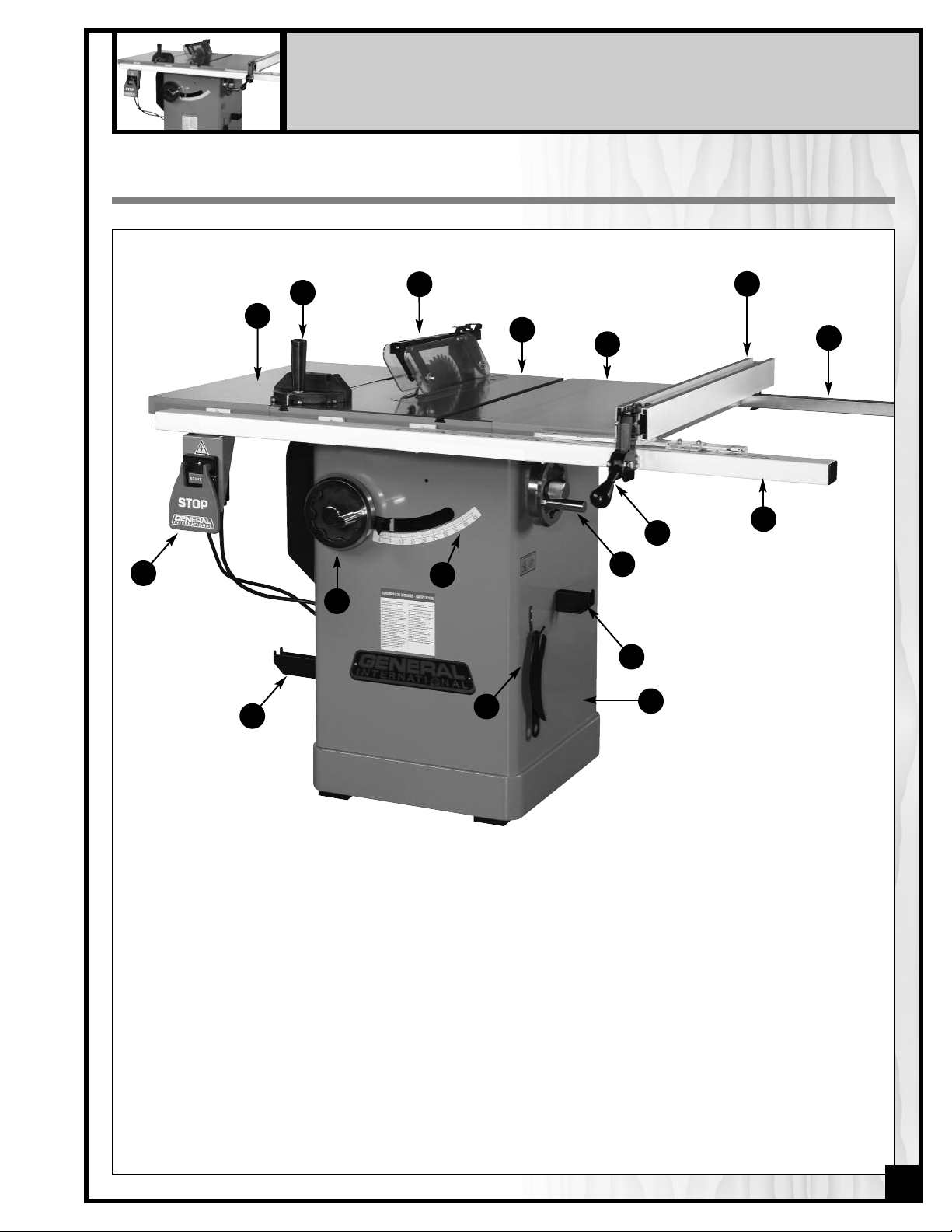
IDENTIFICATION OF MAIN PARTS AND COMPONENTS
Q
B
A
O
P
C
D
N
M
E
I
J
K
L
F
G
H
A- LEFT TABLE EXTENSION
B- MITER GAUGE
C- SPLITTER AND BLADE GUARD ASSEMBLY
D- MAIN TABLE
E- RIGHT TABLE EXTENSION
F- RIP FENCE
G- REAR RAIL
H- FRONT RAIL
I- RIP FENCE LOCKING HANDLE
J- BLADE TILT ADJUSTMENT HANDWHEEL
K- MITER GAUGE STORAGE BRACKET
L- CABINET
M- ARBOR WRENCH STORAGE BRACKET
N- BEVEL SCALE
O- BLADE HEIGHT ADJUSTMENT HANDWHEEL
P- FENCE STORAGE BRACKET
Q- ON/OFF SWITCH
7
Page 8
BASIC FUNCTIONS
This saw has been designed for cutting solid wood as well as manufactured wood materials such as plywood,wood
panelling, particleboard, mdf and other wood based by-products. This saw is not designed for cutting metals nor
for cutting any materials other than wood or wood based stock.
This saw is designed for use with maximum 10" (250mm) diameter blades having a center hole diameter of 5/8".
The blade can be raised to cut a maximum stock thickness of 3" with the blade set 90 degrees to the table. The
blade can be tilted up to 45 degrees to the left for bevel cuts to a maximum stock thickness of 2 1/4". Using any
standard aftermarket 8" diameter stacked dado blade set (not included), the maximum dado cutting capacity of
this saw is 13/16" (21 mm). Note: for safer dado cutting, an optional dado table insert (part number #50-202) can
e purchased through your General International distributor.
b
The 50-200R is supplied with both a riving style splitter/blade guard assembly and a European style riving knife that
are both designed to raise or lower and tilt with the blade, and maintain a consistent distance to the blade at all
imes, regardless of the height or angle of the blade. This can help reduce (but not totally eliminate) the risk of a
t
kickback incident, where the workpiece is thrown back at the operator, by helping to prevent the workpiece from
getting stuck between the blade and the riving style splitter or riving knife (as compared to a traditional stationary
splitter) or from closing up on the back of the blade as it passes through the cut.
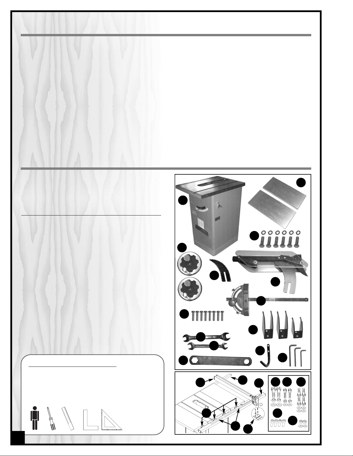
UNPACKING
Carefully unpack and remove the saw and its components from the box and check for damaged or missing
items as per the list of contents below.
NOTE: Please report any damaged or missing items to your
General® International distributor immediately.
LIST OF CONTENTS QTY
SAW ..................................................................................................1
A -
TABLE EXTENSION ............................................................................2
B -
17 MM HEX HEAD BOLT W/WASHER ..............................................6
C -
HANDWHEEL W/LOCK KNOB..........................................................2
D -
EUROPEEN STYLE RIVING KNIFE ......................................................1
E -
COMBINATION RIVING STYLE SPLITTER & BLADE GUARD..............1
F -
MITER GAUGE ..................................................................................1
G -
PHILLIPS HEAD SCREW.....................................................................8
H -
I-14-17 MM OPEN END WRENCH......................................................1
10-12 MM OPEN END WRENCH......................................................1
J -
ARBOR WRENCH .............................................................................1
K -
MITER GAUGE/RIP FENCE STORAGE BRACKET ..............................3
L -
ARBOR WRENCH STORAGE BRACKET.............................................1
M -
ALLEN KEY (6-4-3 MM,1 EACH).......................................................3
N -
T-FENCE ............................................................................................1
O -
REAR RAIL.........................................................................................1
P -
FRONT RAIL ......................................................................................1
Q -
“L” BRACKET......................................................................................4
R -
MEASURING TAPE (LEFT & RIGHT) ...................................................1
S -
FENCE POINTER/VISOR & HARDWARE ..........................................1
T -
12 MM HEX HEAD BOLT W/HEX NUT & FLAT WASHER ...................2
U -
LONG 10 MM HEX HEAD BOLT W/HEX NUT & FLAT WASHER........2
V -
SHORT 10 MM HEX HEAD BOLT W/FLAT WASHER ..........................4
W -
6 MM SOCKET CAP SCREW............................................................4
X -
12 MM HEX NUT & FLAT WASHER....................................................2
Y -
ADDITIONAL REQUIREMENTS FOR SET UP
• Extra person for help with lifting
• Phillips Screwdriver
• Straightedge
• Machinist square or triangle square
B
A
C
D
E
F
G
H
L
I
J
M
K
0
P
Q
N
U V
W
or
R
X
Y
S
T
8
Page 9
PLACEMENT WITHIN THE SHOP /
ESTABLISHING A SAFETY ZONE
HIS MODEL 50-200R 10" LEFT TILT 2 HP TABLE SAW IS HEAVY. DO NOT OVER-EXERT. A HOIST OR FORKLIFT WITH STRAPS
T
HOULD BE USED TO LIFT THIS MACHINE.
S
O LIMIT THE RISK OF SERIOUS INJURY OR DAMAGE TO THE MACHINE, ANY EQUIPMENT USED TO LIFT THIS MACHINE
T
HOULD HAVE A RATED CAPACITY IN EXCESS OF 303 LBS (138KG).
S
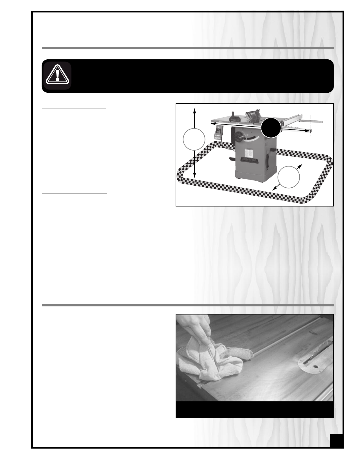
PLACEMENT WITHIN THE SHOP
This machine should be installed and operated
only on a solid, flat and stable floor that is able
to support the weight of the saw (320 Lbs - 146
kg) and the operator.
Using the dimensions shown as a guideline, plan
for placement within your shop that will allow
the operator to work unencumbered and unobstructed by foot traffic (either passing shop visitors or other shop workers) or other tools or machinery.
ESTABLISHING A SAFETY ZONE
For shops with frequent visitors or multiple operators, it is advisable to establish a safety zone
around shop machinery. A clearly defined “no-go” zone on the floor around each machine can help avoid
accidents that could cause injury to either the operator or the shop visitor. It is advisable to take a few moments
to either paint (using non-slip paint) or using tape, define on the floor the limits or perimeter of each machines
safety zone. Take steps to ensure that all operators and shop visitors are aware that these areas are off limits
whenever a machine is running for everyone but the individual operating the unit.
36”
57”
31.5”
CLEAN UP
The protective coating on the saw table prevents
rust from forming during shipping and storage.
Remove it by rubbing with a rag dipped in
kerosene, mineral spirits or paint thinner. (Dispose
of potentially flammable solvent-soaked rags
according to manufacturer’s safety recommendations.)
A putty knife, held flat to avoid scratching the surface, may also be used to scrape off the coating
followed by clean-up with solvent. Avoid rubbing
the saw’s painted surfaces, as many solventbased products will remove paint.
To prevent rust, apply a light coating of paste wax
or use regular applications of any after-market
surface protectant or rust inhibitor.
Tip: With a screw driver, push a solvent-saturated rag into the Tslots to remove the grease.
9
Page 10
ASSEMBLY INSTRUCTIONS
SERIOUS PERSONAL INJURY COULD OCCUR IF YOU CONNECT THE MACHINE TO THE POWER SOURCE BEFORE YOU HAVE
OMPLETED THE INSTALLATION AND ASSEMBLY STEPS. DO NOT CONNECT THE MACHINE TO THE POWER SOURCE UNTIL
C
NSTRUCTED TO DO SO.
I
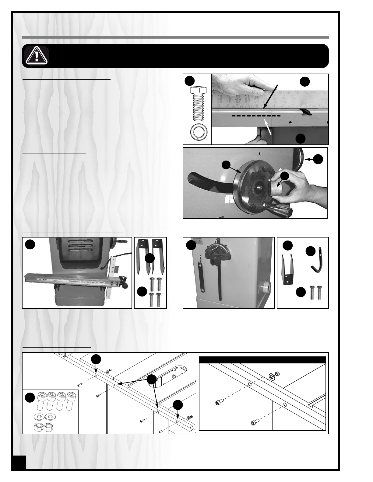
INSTALL THE TABLE EXTENSION WINGS
ttach the table extension wings to the main table
A
using 6 hex head bolts (3 per wing) and 6 lock washers A. Align the table extensions with the table and
oosely attach the bolts. Place a straightedge on the
l
table and extension as shown to align the extension
table B and then tighten down the bolts.
Note: Be sure that the table extension wings are flush with
front edge of table
C.
INSTALL THE HANDWHEELS
1. Install one handwheel onto the shaft at the front of the
saw as shown in A.
Note: The slots in the handwheel must be aligned with the
spring pin on the shaft.
2. Thread a lock knob B into the handwheel shaft to
secure the handwheel in place.
3. Repeat with the second handwheel, on the shaft located on the right side of the saw cabinet, C.
MOUNT THE RIP FENCE STORAGE BRACKETS
B
A
A
level here
flush here
B
C
C
A
B
MOUNT THEMITER GAUGE & ARBORWRENCH STORAGE BRACKETS
C
A
B
C
Install the fence storage brackets A (the two larger
ones) on the left side of the saw as shown in B, using 4
Phillips head screws C.
Install the miter gauge storage bracket A (the smaller
one) and arbor wrench storage bracket B on the right
side of the saw as shown in C, using 2 Phillips head
screws D per bracket.
D
INSTALL THE REAR FENCE RAIL
B
CLOSE UP
C
A
B
Attach the rear rail to the rear of the table using 4 cap screws, 2 flat washers and 2 hex nuts A (1 screw with washer
and nut and both extension wings, B, and 2 cap screws on the main table C. Tighten with the supplied 6 mm Allen
key.
10
Page 11

NSTALL THE FRONT FENCE RAIL
I
B
10 mm
A
12 mm
A
C
12 mm
1. Loosely attach the 4 L-brackets to the front of the table using a 12 mm hex head bolt with hex nut and flat washer on both extension wings, A, and 2 long 10 mm hex head bolts with hex nuts and flat washers on the main
table B, in the assembly order shown.
2. Do not tighten down the nuts; the bolts should not be protruding from the L-brackets, C.
D
E
F
3. Assemble the front rail to the L-backets by fastening three of the four short 10 mm long hex head
bolt with flat washer to the underside of the rail D.
Note: For now, omit the first bolt on the far left of the rail
because this is where you will attach the saw’s On/Off switch.
4. Using the supplied 10-12 mm wrench, tighten down
nuts E that secures the “L” brackets to the table
and bolts F that secures the front rail to the “L”
brackets.
MOUNT THE SWITCH
Attach the ON/OFF switch bracket to the front rail, A, by fastening the fourth hex head bolt with flat washer to the
underside of the leftmost L-bracket B. Tighten with the supplied 10 mm wrench C.
A
C
B
11
Page 12

INSTALL / REMOVE A SAW BLADE
NOTE
This saw is intended for use with 10" (250mm) diameter or less saw blades having a center hole diameter of
5/8". There are many types of blades available to perform specific cutting jobs, such as crosscuts or ripping
only, or for use with plywood, panelling and other products. A good quality specialty blade can produce a
finer finish, be more efficient and place less strain on the saw. Use only saw blades designed for use at a maximum operating speed of 5000 RPM or less. Saw blades should be kept clean and sharp. Never store saw
blades by stacking them directly in contact with each other. Place a layer of cardboard or similar material
between the blades to keep them from coming into contact with each other.
E SURE THE SAW IS UNPLUGGED AND COMPLETELY DISCONNECTED FROM THE POWER SOURCE WHENEVER INSTALLING
B
OR REMOVING A SAW BLADE!
INSTALL A SAW BLADE
D
A
C
FRONT
BLADE
DIRECTION
B
1. Remove the table insert plate A. Then, remove the
arbor nut B & flange C.
E
TIGHTEN
F
G
3. With the blade raised to maximum height
the flange and arbor nut, then press on the arbor
lock button E so the blade & arbor won’t turn as you
tighten the arbor nut clockwise (toward the rear of
the saw) F with the supplied arbor wrench G.
BEFORE TURNING ON THE SAW, MAKE SURE THE ARBOR LOCK IS DISENGAGED (POPS UP) BY TURNING THE BLADE A
FRACTION TO UNLOCK. TURN THE BLADE BY HAND ONE FULL ROTATION TO MAKE SURE THE ARBOR/BLADE TURNS
FREELY.
, re-install
2. Install a saw blade on the arbor so that the openings between the teeth face the front of the saw
D (the blade spins in the counter-clockwise direction).
LOOSEN
To remove a saw blade
Perform the same procedure turning the arbor nut in
the opposite direction.
NOTE
When tightening the arbor nut, take care not to over tighten as this will make it very difficult to remove later.
Because the rotation of the blade runs counter to the direction of the threads on the nut, the blade is essentially tightening itself to the nut whenever the saw is running. Though there are no hard and fast rules for how
much torque is required, the arbor nut should be always tightened hand-tight and just slightly beyond “snug”.
12
Page 13

INSTALL AND ADJUST RIVING KNIFE
ELECT A RIVING KNIFE
S
Two riving knives are provided:
- A combination riving style splitter and blade guard with
nti-kickback pawls A;
a
- A European style riving knife without blade guard B.
The riving knife must always be used with a blade guard.
f you already own an independently attached blade-
I
guard such as our Excalibur 50-EXBC10, use the riving knife
B. If you do not already own a blade guard, use the
splitter/blade guard assembly A.
HE BLADE MUST NEVER REMAIN EXPOSED WHEN USING THE SAW. TO PREVENT THE RISK OF SERIOUS INJURIES,
T
ALWAYS COVER THE BLADE WITH A BLADE GUARD.
REMOVAL / INSTALLATION
ALWAYS TURN OFF AND UNPLUG THE SAW BEFORE REMOVING / INSTALLING A RIVING KNIFE.
B
A
1. Set the blade to 90º and raise it to its highest position.
(Refer to “Blade height and tilt adjustment” instructions
on page 17 if needed).
2. Remove the table insert.
3. If already installed, remove the splitter or riving knife
by loosening the locking lever A and pulling the splitter or riving knife up out of its mounting bracket.
4. To install
knife into the slot in the mounting bracket and push
downward until it bottoms out, then tighten the locking
lever A to lock it in place.
5. Re-install the table insert.
: Fit the bottom end of the splitter or riving
LEVEL THE TABLE INSERT
Place the insert into the table and use a straightedge to
determine whether the insert is level with the table top A.
Turn each of the 6 adjusting screws A with the supplied
Allen key until done.
Suggestion: Start by adjusting one rear screw and its
diagonal opposite in front, then tweak the remaining
screws.
Note: If the sawblade has already been installed, use the raising handwheel to lower the blade below the table surface
before leveling the insert.
A
A
13
Page 14

ALIGN THE RIP FENCE
LIGN THE RIP FENCE PARALLEL TO THE BLADE
A
THE RIP FENCE MUST BE PARALLEL TO THE BLADE DURING OPERATION. FAILURE TO SET THE RIP FENCE PARALLEL TO
THE BLADE CAN RESULT IN KICKBACK AND POSSIBLE SERIOUS INJURY.
o make satisfactory rip cuts, your fence must be aligned perfectly parallel with the saw blade.
T
1. Slide the fence over to the right T-slot on your saw
table top A. Push down the locking lever to lock the
fence in place B and make a visual check that the
fence is parallel with the T-slot all along its length.
Also, you can place a small 3/4”thick block of wood,
upright into the T-slot and slide it from the front
to the back checking its distance from the left edge
of the fence.
2. If the fence is not parallel, it can be adjusted by using
the supplied 4 mm Allen key to turn one or both of the
screws C or D. Do this slowly, just an eighth to a quarter turn at a time, or you will quickly overshoot the desired adjustment.
Note: It is always good practice to periodically recheck the
alignment of your fence to the blade.
A
B
D
ALIGN THE RIP FENCE PERPENDICULAR (90°) TO THE TABLE
Place a machinist square on the table against the fence
and look for a gap between the square and the fence
(bottom and top) or the table. If needed, adjust either of
the two plastic set screws E or F, to tilt the fence slightly
and square it to the table.
14
C
F
E
Page 15

INSTALL THE MEASURING TAPE AND POINTER
0
1
2
3
0
1
2
3
A
B
1. Using a Phillips screwdriver, attach the pointer /
visor to the right side of the fence base as shown.
2. Set the blade to 90° and raise it to the maximum
height A.
3. Put the fence on the rails and move it till it slightly
touches the right side of the blade B.
D
E
F
G
C
4. Lock down the fence C.
5. Make a pencil mark on the rail, in line with the point-
er’s center mark, D. Then, unlock the fence and put
is aside for now.
* The tape should sit about 1/4 inch back from the front edge of the rail.
* Try removing only an inch of backing strip from the start of the tape, stick that down, then remove the rest of the ba-
cking and pull the measuring tape taut to the end of the rail slot and carefully lower it against the rail.
* For accurate readings, the tape must be placed straight parallel with the rail, with no folds along its length.
6. *Remove the first inch (approx.) of backing strip
from the start of the longer piece of measuring tape
(the one with the zero on the left), E. Gradually remove the rest of the backing as you install the tape
along the front rail as shown, F, with your pencil mark
G as the zero-point of the tape.
H
I
7. Re-install the fence on the front rail, against the
blade, and lock it down.
Loosen the pointer screws and slide the pointer right
8.
or left, H, so that its center mark is in line with the
zero-point of the tape, I. Tighten the screws to lock
the pointer in place.
J
9. For the final check, slide the fence to the right so the
pointer points to the 2-inch mark, J. Use scrap wood
to make several rips. If the cuts don’t measure exactly 2 inches wide, re-adjust the pointer.
15
Page 16

ON
0. Repeat steps 3 to 9 with the fence to the left of the
1
blade this time, aligning the center mark of the pointer with the zero of the second half of the measuring
tape, K.
Note: Recheck and, if necessary, readjust the left and right
pointers against the zero-point of both measuring tapes whenever you change blades. Different blades have different thicknesses, which can throw off the pointer a few fractions.
CONNECTING TO A DUST COLLECTOR
• There is a 4" dust outlet located on the lower left of the
saw cabinet allowing for the connection to a dust collection system (not included).
• Be sure to use appropriate size hose and fittings (not
included) and check that all connections are sealed
tightly to minimize airborne dust.
• If you do not already own a dust collection system
consider contacting your General® International distributor for information on our complete line of dust collection systems and accessories or visit our website at
www.general.ca
K
ALWAYS TURN ON THE DUST COLLECTOR BEFORE
STARTING THE SAW AND ALWAYS STOP THE SAW
BEFORE TURNING OFF THE DUST COLLECTOR.
BASIC ADJUSTMENTS & CONTROLS
CONNECTING TO A POWER SOURCE
TO AVOID RISK OF SHOCK OR FIRE DO NOT OPERATE THE UNIT WITH A DAMAGED POWER CORD OR PLUG. REPLACE DAMAGED CORD OR PLUG IMMEDIATELY.
TO AVOID UNEXPECTED OR UNINTENTIONAL START-UP, MAKE SURE THAT THE POWER SWITCH ON THE SAW IS IN THE OFF
POSITION BEFORE CONNECTING TO A POWER SOURCE.
Once the assembly steps have been completed, uncoil
the power cord and plug it into an appropriate outlet.
Refer back to the section entitled “ELECTRICAL REQUIREMENTS” and make sure all requirements and grounding
instructions are followed.
SWITCH OFF
When cutting operations have been completed unplug
the saw from the power source.
16
Page 17

1/4”
1/4”
ON/OFF SWITCH & SAFETY PIN
he ON/OFF switch assembly A is equipped with a lock-out
T
safety pin B. When the pin is installed through the green
“on”button C, the machine cannot be started.
To start the machine
Lift the red stop switch panel and remove the lock-out pin.
ower the stop panel and push the green “ON” button.
L
Wait for the saw blade to reach full speed before cutting.
To stop the machine
Push on the RED “STOP” panel and wait for the blade to
come to a complete stop.
When you have finished using the machine be sure to re-install the lock-out pin and unplug the saw from the
power source.
A
B
C
BLADE HEIGHT & TILT ADJUSTMENT
BLADE HEIGHT ADJUSTMENT
The blade height adjustment handwheel A is located on
the front of the saw, and there is a lock knob B on the
handwheel that allows you to lock the wheel and secure
the blade at the desired height.
B
To raise or lower the blade:
1. Loosen the blade height lock knob B by turning
counterclockwise.
2. To raise the blade:
To lower the blade:
clockwise.
3. With the blade set to the desired height, tighten the
lock knob to lock the blade.
TO LIMIT YOUR EXPOSURE TO THE BLADE AND ALSO TO MAXIMISE THE EFFECTIVENESS OF THE ANTI-KICKBACK
PAWLS (WHEN USING THE RIVING STYLE SPLITTER & BLADE GUARD), NEVER TAKE MORE BLADE HEIGHT THAN
IS REQUIRED TO COMPLETE THE CUT. WHEN SETTING THE BLADE HEIGHT FOR THROUGH-CUTS (CUTS ALL THE
WAY THROUGH THE THICKNESS OF A BOARD) SET THE HEIGHT OF THE BLADE TO ROUGHLY 1/4" HIGHER
THAN THE THICKNESS OF THE BOARD.
turn the handwheel clockwise.
turn the handwheel counter-
BLADE TILT (BEVEL) ADJUSTMENT
The blade tilt (bevel) adjustment handwheel C is located
on the right side of the saw and there is a lock knob D on
the handwheel that allows the user to lock the tilting mechanism and secure the blade at the desired angle
To change the angle of the blade:
1. Loosen the lock knob D by turning it counterclockwise.
2. Turn the handwheel C left or right as required to set the
blade to the desired angle. The blade can be tilted to
the left anywhere from 0° (90° to the table) to 45°.
3. With the blade tilted to the desired angle, tighten the
lock knob D by turning it clockwise to lock the tilting
mechanism and secure the blade at the desired angle.
A
D
C
17
Page 18

OPERATING INSTRUCTIONS
ERIFY ALL CHECK POINTS BEFORE STARTING. FAILURE TO COMPLY CAN RESULT IN SERIOUS INJURIES.
V
• Make sure that the arbor nut is secure and that the blade is firmly tightened snug on the arbor.
• Check that the blade angle and height lock knobs are tight.
• If ripping, make sure the fence lock lever is engaged and that the fence is parallel to the blade.
• If cross cutting, make sure the miter gauge is locked tight.
• While using the saw, be sure to wear safety glasses at all times.
• Make sure that the blade guard/splitter assembly or riving knife is properly installed and aligned with the
blade, and that the anti-kickback pawls are functioning.
TYPES OF CUTS
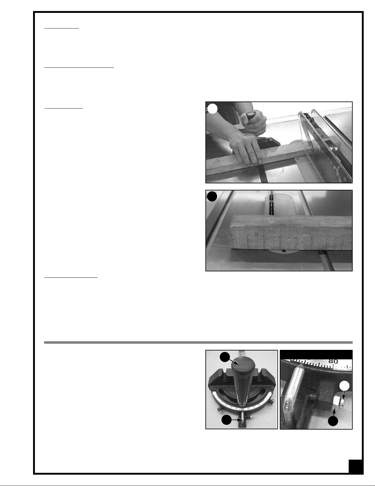
RIPPING
Cutting a wood plank or sheet of plywood lengthwise to
reduce its width is called “ripping.” To rip stock, hold the
work with both hands pushing it into the blade as well as
firmly against the rip fence so that it is cut straight A.
• The work to be cut must have a straight edge to ride
against the fence and must be flat to make solid con
tact with the table during the cut in order to avoid “kickback”(a blade jam causing the wood to fly backwards
and hit you).
• Never rip or cut wood without using the fence or miter
gauge to guide it because the stock could kickback.
• Always use the blade guard and splitter assembly when cutting wood. It has anti-kickback fingers and a splitter
to prevent the saw “kerf” (the slit cut by the blade) from closing and binding the blade, which can overload
and/or stall the motor or cause the blade to lift and eject the workpiece towards the front of the saw at very high
speeds. The blade guard keeps your fingers away from the blade and also reduces the amount of sawdust flying free.
• Although certain operations require the removal of the blade guard and splitter assembly, it should always be
replaced for regular cutting.
• Never stand in the line of the blade when ripping.
• Raise the saw blade only about 1/4" higher than the workpiece to be cut.
As you complete the rip, the wood will either remain on
the table, tilt up to be caught on the end of the guard,
or fall onto the floor (or outfeed table). The waste part of
the stock remains on the table to be removed only after
the saw is stopped (unless it is large enough for immediate safe removal).
If the work to be ripped is narrow, it is safer to use a push
stick, rather than the hands, to feed it into the blade B.
Push sticks with non-slip grippers can be purchased, but
a shop-made one works just as well.
When ripping extremely narrow stock that may not clear
the width of the blade guard, or very thin material such
as paneling, which may slip between the underside of
the fence and the table surface, a strip of wood as an auxiliary guide can be attached to the fence.
A
B
18
NEVER REACH IN TOWARDS THE BLADE WHILE THE BLADE IS STILL SPINNING! WHENEVER A RIP CUT IS COMPLETED,
TURN OFF THE SAW AND WAIT FOR THE BLADE TO COME TO A COMPLETE STOP BEFORE REACHING IN TO REMOVE THE
WORKPIECE OR THE WASTE MATERIAL.
Page 19
BEVEL RIPPING
Bevel ripping is performed the same as ripping but with the saw blade set to an angle not perpendicular with the
table surface. After changing the bevel angle verify the alignment of the guard and splitter; make sure there is
clearance with the saw blade.
IPPING SMALL WORK PIECES
R
Do not attempt rip cuts if the work piece is too small, as this will oblige you to place your hands too close to the
blade and put you at serious risk of injury. When ripping narrower widths; use a push block or a push stick in order
to avoid placing hands near the blade.
CROSS CUTTING
Cutting against the grain, to shorten the length of a
board is cross cutting. With some smaller-sized and rectangular pieces, you often have the choice of ripping
or cross cutting. Always use the miter gauge, C, when
cross cutting; never cut a piece unsupported. The miter
gauge may be used in either slot, but most operators
prefer the left groove for typical work. When the blade
is tilted for bevel cutting, use the table slot that does not
cause interference with your hand or the saw blade
guard.
To begin cross cutting, place the work on the miter
gauge and, with the motor OFF, slide it up close to the
blade to align the outer edges of the teeth with your
cut mark, D. Keep a firm grip as you pull the miter
gauge and the wood back away from the blade.
Lower the blade guard, turn on the saw and make the
cut. When the work is cut through, move one or both
cut pieces — if long enough to handle without danger
— immediately off to the side, away from the turning
blade. Turn off the motor.
C
D
BEVEL CROSS CUTTING
This procedure is the same as cross cutting except that the blade is set to an angle other than 0. After changing the
bevel angle, verify the alignment of the guard and splitter and verify that there is clearance with the saw blade.
ADJUSTING AND USING THE MITER GAUGE
The miter gauge supplied with your saw has accurately
adjusted index stops at 90° and 45° to the right and left,
with a 30° maximum.
To use a setting other than 90°, loosen the lock knob A by
turning it counter-clockwise,pull the stop-lock pin B, rotate
the miter head to 45°, or any angle shown on
the numerical guide. Turn the lock knob clockwise to
tighten it.
To check the accuracy of the miter gauge’s factory settings, set it at 90° and check it with an L-square or T-square.
To verify the setting, make a test cut in scrap stock and
then use a square to check the cut piece. Repeat adjustment if necessary.
If the miter gauge needs adjusting, manually turn the head so the pointer is where you think it ought to be,
tighten the lock knob and loosen the nut C. Turn the adjusting screw D until it touches the stop-lock pin. Tighten down
the nut again. Recheck the angle by making another test cut. Repeat, if necessary, until a true 90° is achieved.
A
B
CLOSE UP
D
C
19
Page 20

ADDING AN AUXILIARY FENCE TO THE MITER GAUGE
To ensure a true 90° crosscut, especially with longer pieces of wood that need more support than the narrow
miter gauge head can provide, an auxiliary wood fence
can be attached.
Make sure the wood for the fence is straight, and not
bowed. It should be about 2" wide and extend about 12"
from either side of the miter head. Drill 2 holes in the wood
corresponding to those on the miter head and use bolts
and nuts to secure the wood fence to the head A.
To use the miter gauge with an auxiliary fence, first notch
the fence with the saw blade a bit higher than the nut B. Measure and draw a cutline on your wood C then place
it on the miter fence. Position your cutline against the notch. Turn on the saw, slide the work up until it is cut through,
but don’t cut off the fence.
LARGER VIEW
B
C
A
FRONT VIEW
Marking Wood
blade on the waste side of the mark. Don’t cut through the
middle of the measurement line or you’ll reduce your
desired board length by half the width of the saw blade!
For accurate work, don’t mark your cut with a fat pencil
line E. A narrow dash, with a sharp pencil point is best D.
Encircle the dash so you’ll find it again and add a small X
to indicate the waste or cut-off side. Pencils, like saw
blades, have thickness. When squaring off from the cut
mark, align your square to allow for pencil clearance,
which will be about 1/16" away from the drawing edge of
the square F.
: If you measure a cut for 24", line up the
MITER CUTS
This operation is the same as cross cutting, except the
miter gauge is set to an angle other than 0. Hold the work
piece firmly against the miter gauge and feed the work
piece slowly into the blade to prevent it from moving
during the cut.
COMPOUND MITERING
This is a combination of bevel cross cutting and mitering.
It is infrequently used. Follow instructions for both bevel
cutting and mitering.
F
D
E
USING A DADO HEAD BLADE
Dadoing is cutting a “rabbet” or a wide groove into the
work. A dado blade A (not supplied with your saw) usually consists of two outer blades and several interior cutters.
These can be adjusted to cut grooves from 1/8" to 3/4" for
making shelves, joints and tenoning. Set the blade’s width
according to the instructions.
After adjusting its width, mount the dado blade on your
saw just like a regular blade. You’ll need an optional
dado insert B (Item # 50-202) to replace the standard one
that comes with your saw. Use the fence to line up the cut.
The blade guard/splitter must be removed when dadoing. Never use the dado blade in a bevel position.
ALWAYS VERIFY THE DADO BLADE CLEARANCE BEFORE CONNECTING THE SAW TO THE POWER SOURCE. RE-ATTACH THE GUARD
AFTER DADO CUT IS FINISHED. THE MAXIMUM DADO HEAD WIDTH FOR THIS SAW IS 3/4" AND THE MAXIMUM DADO BLADE
DIAMETER IS 8".
20
A
B
Page 21

MAINTENANCE & ADJUSTMENTS
C
D
A
B
AKE SURE THE SAW HAS BEEN TURNED OFF AND UNPLUGGED FROM THE POWER SOURCE BEFORE PERFORMING ANY MAIN-
M
TENANCE.
PERIODIC MAINTENANCE
Inspect/test the ON/OFF switch before each use. Do not operate the saw with a damaged switch - replace a
•
damaged switch immediately
• Inspect the saw blade for damage or chipped teeth before each use. Replace a damaged or chipped blade
immediately. Never operate the saw with a damaged or chipped blade
Keep the saw table clean and free of dust, pitch or glue. An occasional light coating of paste wax can be used
•
to protect the cast-iron surface. Ask our local distributor for suggestions on table top cleaners and cast-iron surface protection based on what is readily available in your area.
• Occasionally open the cabinet door and brush off and vacuum out accumulated dust from inside the cabinet and on the blade tilting gears and on or around the motor.
• Periodically inspect the power cord and plug for damage. To minimize the risk of electric shock or fire, never
operate the saw with a damaged power cord or plug. Replace a damaged power cord or plug at the first
sign of damage.
• To minimize airborne dust particles periodically inspect all dust collection fittings – re-tighten as needed.
LUBRICATION
Keep the blade height adjustment mechanism A (accessible by the motor cover door on the left side of the saw)
as well as the blade tilt mechanism B well lubricated and
free of dust or debris. Clean and remove dust, debris, and
old lubricant as needed depending on frequency of use.
After cleaning, reapply lubricant as needed.
Note: Use any all-purpose grease, available at any hardware store).
The motor and all bearings are sealed and permanently
lubricated – no further lubrication is required. No other
part of this table saw needs lubrication.
A
B
ADJUSTING THE 45° & 90° BEVEL STOPS
1. Disconnect the machine from the power source.
2. Raise the blade to its highest position and lift the blade
guard.
3. Loosen the bevel lock knob and turn the blade tilting
handwheel clockwise until it stops.
4. Verify the angle of the blade with a combination
square from the left side of the blade, keep the square
flat against the table and against the flat part of the
blade - Do not touch the teeth or the table insert.
If the blade angle is incorrect, loosen the two set screws D
and manually turn the 90° stop nut C one full counterclockwise turn.
Turn the handwheel until the blade is at 90° to the table surface. Then re-tighten the 90° stop nut clockwise until slight
resistance is felt, then re-tighten the set screw. Do not over
tighten the stop nut.
Verify the 45° setting by tilting the blade as far as possible to
the left and,using the square,check the angle and if needed adjust as for the 90° stop,this time using the rightstop nut
A and set screws B.
21
Page 22
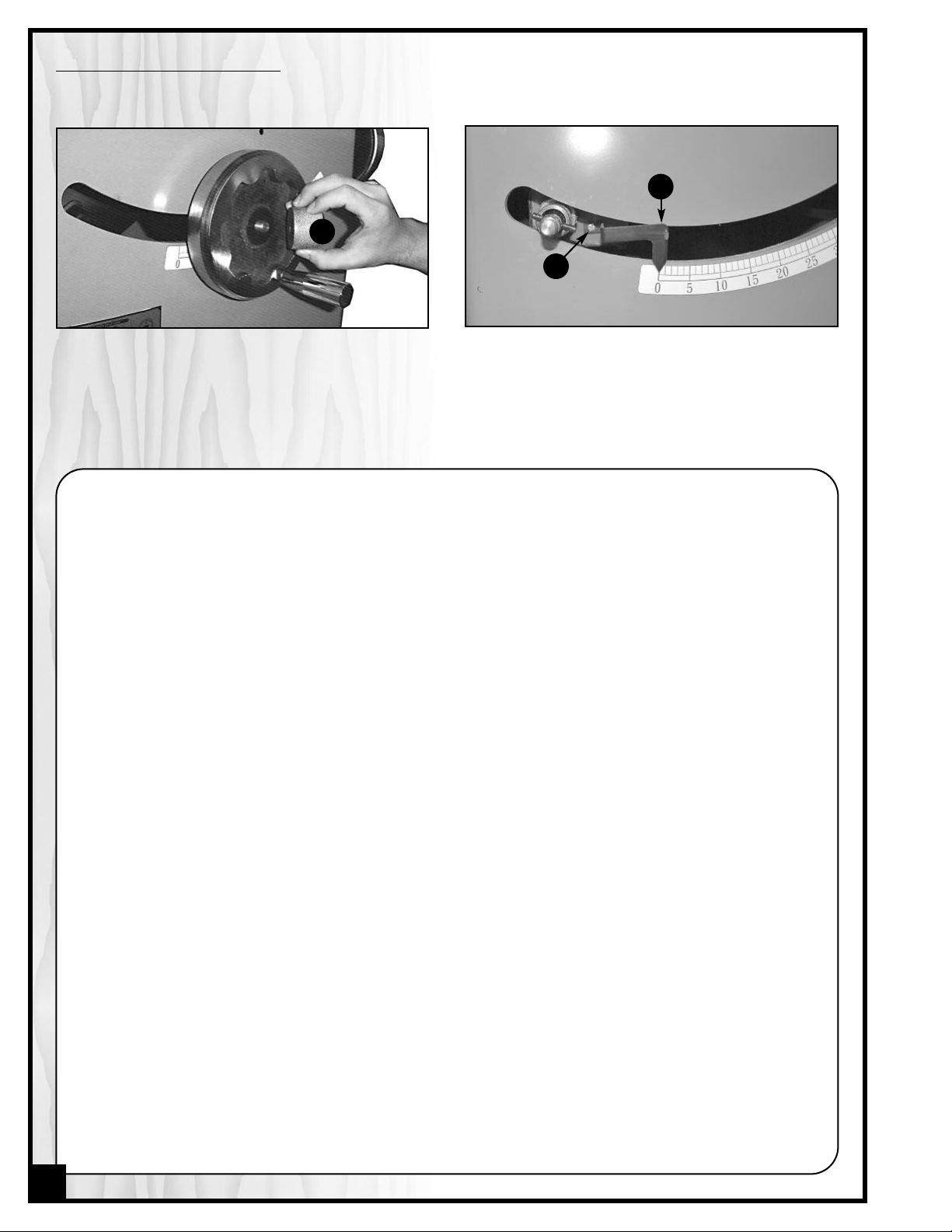
ADJUSTING THE BEVEL ANGLE POINTER
The bevel pointer should read “0” when the blade is at 90° to the table. If not, with the blade set 90° vertical to the
table, proceed as follows:
C
A
B
1. Remove the handwheel by loosening the hand
wheel lock knob A.
Notes
2. Once the handwheel has been removed, loosen
the Phillips head screw B on the pointer mounting
bracket with a screwdriver and manually align the
pointer C with the zero on the bevel scale, then retighten the screw and re-attach the handwheel.
22
Page 23
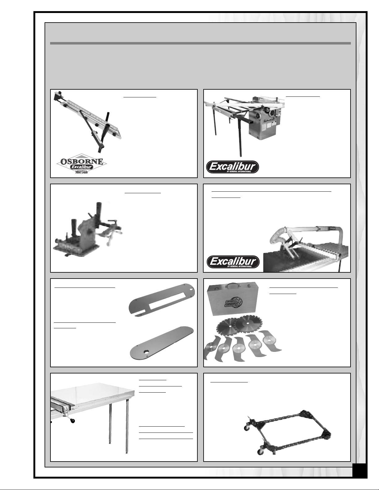
RECOMMENDED OPTIONAL ACCESSORIES
We offer a large variety of products to help you increase convenience,productivity,accuracy and safety when
using your saw. Here’s a small sampling of optional accessories available from your local General International
dealer.
For more information about our products, please visit our website at www.general.ca
Miter guide
#50-EB3
Quickly and easily finds any
angle. Rock solid triangular
design is reversible for use on
either side of the blade.
Adjustable fence for tight
blade clearance, telescoping fence extension and
sliding flip up stop for accurate repeat cuts. A “must
have” for any serious hobbyist.
Tenoning Jig
#50-050
Solid cast iron. Fits left or
right tilt saws for safe and
accurate tenoning.
Sliding Table
#50-SLT60 or 50-SLT40
For accurate crosscutting
or mitering of wide panels; 49” for SLT40 or 62” for
SLT60. Featuring a stable
rock solid design that
runs on smooth roller
bearings allowing the
user to walk large panels
through the cut with ease.
.
Overarm Blade Cover – With Dust Collection
Capability - #50-EXBC10
Maximize dust collection without compromising safety.
Easy to install and simple to use, see-through blade cover.
4" main boom with 3" inner boom. Unique design mounting bracket: pivots away or removes completely in seconds.
Dado insert - #50-202
Fits left tilt model 50-200R only,
for use with dado blades up
to 3/4" maximum width.
Zero Clearance insert
#50-203
Eliminates space between
the blade and insert to help
reduce tear-out and airborne
dust. Raise the blade through
the insert and custom cut to
your blade kerf.
Melamine
Extension Table
27” X 36”
#50-105
Steel Adjustable
Support Leg Set (2)
for Extension Table
#50-115
7 Piece Deluxe 8" Dado
blade set – #55-185
(2) 24 tooth exterior blades. Standard 5/8" (16 mm) bore. Maximum 6000 RPM. Makes 1⁄8" to
13⁄16" (3 to 21 mm) grooves. Antikickback design. Convenient &
sturdy wooden storage case
included.
Mobile base
# 50-025
Easily roll your table saw anywhere in your shop. Load
capacity: 500 lbs. Wheels lock when
equipment is in use.
23
Page 24
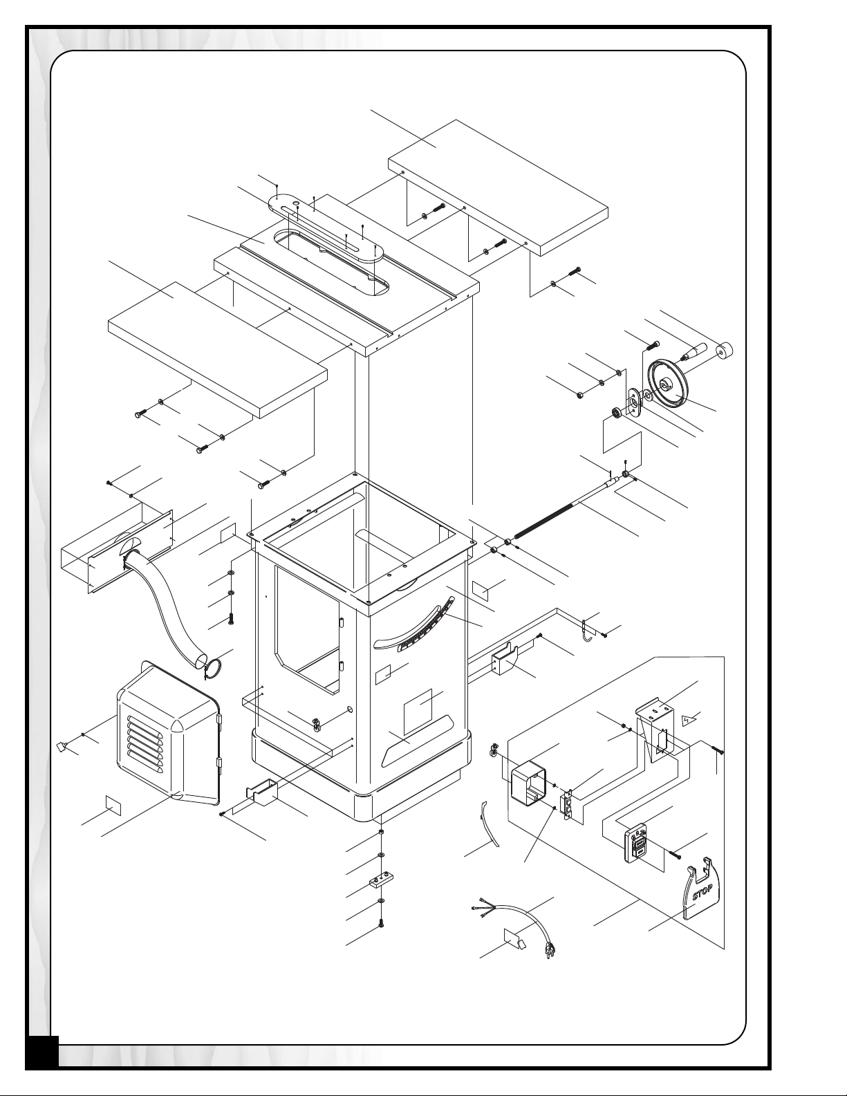
1a
3
59
2
61
60
61
60
60
61
10
4a
9
8
7
95
66
67
75
6
67
66
65
71
70
5
2a
64
73
94
15
13
13
11
16
129
97
17
97
98
63
139
139
69
76
110
76
111
109
76
79
114
115
113
117
119
12
127
130
131
128
118
132
134
96
14
72
13A
133
138
76
140
141
142
CABINET AND TABLE
24
Page 25
85
84
83
62
26
82
56
54
53
52
57
30
29
30
24
75
24
74
56
55
25
39
89
87
27
28
90
87
33
6
93
32
68
31
7
34
76
35
90
36
42
91
23
37
50
51
80
43
38
44
22
49
48
47
46
81
45
80
78
21
20
19
77
76
18
58
65
66
43
86
73
66
65
119
121
122
123
124
125
126
112
116
121A
41a
91
134
135
136
115
114
71
108
107
103
101
67
102
100
99
71
106
105
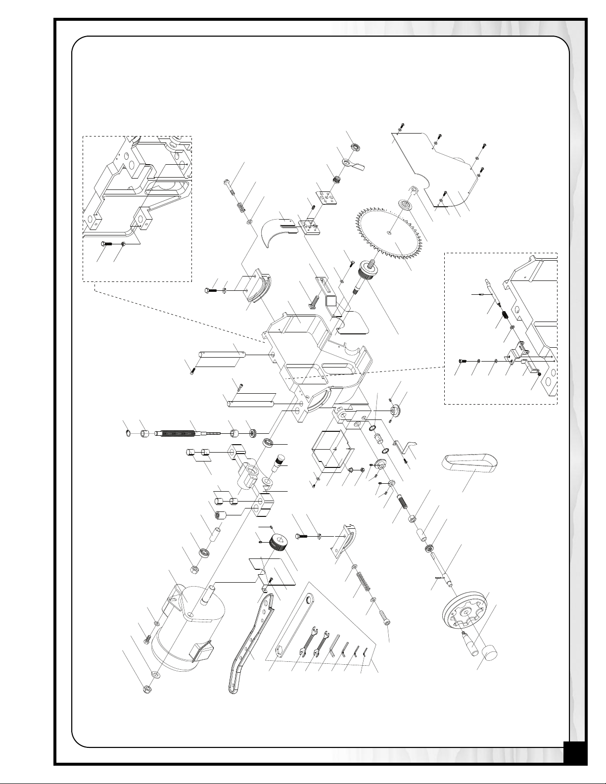
104
BLADE TILTING MECHANISM
25
Page 26

26
PARTS LIST - 50-200R
PARTS N0. REF. N0. DESCRIPTION QTY
50200R-01A 13300001 MAIN TABLE 1
50200R-02 E1210005 EXTENSION WING (LEFT) 1
50200R-02A E1210005 EXTENSION WING (RIGHT) 1
50200R-03 12700003B TABLE INSERT 1
50200R-04A 13300002B SAW CABINET 1
50200R-05 13200004 MOTOR COVER DOOR 1
50200R-06 10105056A HANDLE 2
50200R-07 11500048 HANDWHEEL 2
50200R-08 13200032 WHEEL COVER 1
50200R-09 13200013G TILT ADJUSTMENT ROD 1
50200R-10 J1330001 ANGLE SCALE 1
50200R-11 WG000001 STOP PANEL 1
50200R-12 S0030324 PHILLIPS HEAD SCREW 2
50200R-13A WG000002 ON/OFF SWITCH ASSEMBLY 1
50200R-14 10105053G SWITCH PLATE 1
50200R-15 WG000003 SWITCH BOX 1
50200R-16 L0000132A POWER WIRE 1
50200R-17 10401029 FOOT PAD 4
50200R-18 13300015 DUST PLATE 1
50200R-19 10105069Q FLANGE 1
50200R-20 B0000008G BLADE 1
50200R-21 13300008 ARBOR 1
50200R-22 13300011 GUARD MOUNTING BRACKET 1
50200R-23 13300005 SAW CHUTE 1
50200R-24 13200007 ROD 2
50200R-25 13300006 ARBOR BRACKET 1
50200R-26 M1330001 MOTOR 1
50200R-27 13300012 MOTOR PLATE 1
50200R-28 13200009 MOTOR PULLEY 1
50200R-29 13200016 HEIGHT ADJUSTMENT SCREW 1
50200R-30 20900028 BUSHING 2
50200R-31 13200014G ARBOR 1
50200R-32 13200033 SPACING COLLAR 1
50200R-33 13200027 SLEEVE 1
50200R-34 11105064 ROD CAP 1
50200R-35 13300017 ANGLE POINTER 1
50200R-36 20900022 GEAR 2
50200R-37 V13207190 BELT 1
50200R-38 13300010 GEAR COVER 1
50200R-39 20701006 BEARING 1
50200R-41A S0010865M CAP SCREW 1
50200R-42 11105081 SPRING 1
50200R-43 13200029 TRUNNION 2
50200R-44 12700057 SQUARE HEAD BOLT 1
50200R-45 12300118J RIVING KNIFE MOUNTING BLOCK 1
50200R-46 12300125J RIVING KNIFE CLAMPING PLATE 1
50200R-47 12700059 HEX. NUT 1
50200R-48 12700058 LEVER 1
50200R-49 S009AN04 NUT 1
50200R-50 11102020 FLANGE BOLT 1
50200R-51 11105080 SPRING 1
50200R-52 C9001920 BEARING 4
50200R-53 20900019 SCREW BUSHING 1
50200R-54 12900037 SLEEVE 1
50200R-55 12700013 SHAFT 1
50200R-56 C1206202A BEARING 2
50200R-57 C5151102 BEARING 1
Page 27

PARTS LIST - 50-200R
PARTS N0. REF. N0. DESCRIPTION QTY
0200R-58 13200028 RING 1
5
50200R-59 S0050505M SET SCREW 10
50200R-60 S0021025M HEX. BOLT 6
0200R-61 S0231000M LOCK WASHER 6
5
50200R-62 S0211021 FLAT WASHER 7
50200R-63 C1106201 BEARING 1
0200R-64 13200031 POSITION RING 1
5
50200R-65 S0020820M HEX. BOLT 8
50200R-66 S0230800M LOCK WASHER 10
0200R-67 S0210516 FLAT WASHER 7
5
50200R-68 C5151104 BEARING 1
50200R-69 13200034 POSITION NUT 2
50200R-70 S0020510M PULL KNOB 1
50200R-71 S0210303 FLAT WASHER 8
50200R-72 LC1430402 MOTOR WIRE 1
50200R-73 S0310525 PIN 2
50200R-74 S0010820M CAP SCREW 2
50200R-75 S0010835M CAP SCREW 4
50200R-76 S0030515M PHILLIPS HEAD SCREW 15
50200R-77 11105068 ARBOR NUT 1
50200R-78 S0020625M HEX BOLT 2
50200R-79 S1017W-2 STRAIN RELIEF 3
50200R-80 S0210402 FLAT WASHER 3
50200R-81 S0050810M SET SCREW 4
50200R-82 S0111400L HEX NUT 1
50200R-83 S0021020M HEX BOLT 1
50200R-84 S0210540 FLAT WASHER 1
50200R-85 S0120580 LOCK NUT 1
50200R-86 S0010508M PHILLIPS HEAD SCREW 2
50200R-87 S0050510M SET SCREW 4
50200R-89 S0120800M LOCK NUT 1
50200R-90 S0050103 SET SCREW 4
50200R-91 S0210500B FLAT WASHER 1
50200R-93 S0112000M HEX. NUT 1
50200R-94 S00505605M SET SCREW 2
50200R-95 S0110800M HEX. NUT 2
50200R-96 S0030512 PHILLIPS HEAD SCREW 4
50200R-97 S0210516 FLAT WASHER 8
50200R-98 S0110500 HEX. NUT 4
50200R-99 13200026 MOUNTING PLATE 1
50200R-100 12700049A PUSH BAR 1
50200R-101 12700050A PUSH HANDLE 1
50200R-102 10102032 SPRING 1
50200R-103 S0120800M LOCK NUT 1
50200R-104 S0310325 PIN 1
50200R-105 S0010520M CAP SCREW 2
50200R-106 S0230500M LOCK WASHER 2
50200R-107 S0020640M HEX BOLT 2
50200R-108 S0110600M HEX NUT 2
50200R-109 11500006 FENCE STORAGE BRACKET 2
50200R-110 11500044 MITER GAUGE STORAGE BRACKET 1
50200R-111 11500045 WRENCH HOOK 1
50200R-112 12300154 PUSH STICK 1
50200R-113 13200025 DUST OUTLET PLATE 1
50200R-114 S0030412M PHILLIPS HEAD SCREW 7
50200R-115 S0210300B FLAT WASHER 7
27
Page 28

PARTS LIST - 50-200R
B7
B1
B13
B4
B10
B5
B11
B2
B6
B12
B8
B9
B3
PARTS N0. REF. N0. DESCRIPTION QTY
50200R-116 13000004A RIVING KNIFE 1
50200R-117 S1500212C DUST HOSE 1
50200R-118 12300156B HOSE CLAMP 2
50200R-119 11305031 LOCK KNOB 2
50200R-121A N/A TOOL KIT 1
50200R-121 10105090Q ARBOR WRENCH 1
50200R-122 S0911012 OPEN END WRENCH 14-17 MM 1
0200R-123 S0911417 OPEN END WRENCH 10-12 MM 1
5
50200R-124 S0910206 ALLEN KEY 6 MM 1
50200R-125 S0910204 ALLEN KEY 4 MM 1
50200R-126 S0910203 ALLEN KEY 3 MM 1
50200R-127 JG133002 LABEL 1
50200R-128 JG133003 LABEL 1
50200R-129 JG133004 WARNING LABEL 1
50200R-130 JG000001 WARNING LABEL 1
50200R-131 JG000004 LOGO LABEL 1
50200R-132 J2091001 I.D. NAME PLATE 1
50200R-133 J30301002 WARNING LABEL
50200R-134 S0910225 L-WRENCH 2.5 MM 1
50200R-135 S0220302 LOCK WASHER 2
50200R-136 S0520015 C-RING 1
50200R-138 S0212137 FLAT WASHER 1
50200R-139 S0050608M SET SCREW 1
50200R-140 S0110500M NUT 2
50200R-141 S0220500M LOCK WASHER 2
50200R-142 S0220300 SPROCKET WASHER 2
MITER GAUGE ASSEMBLY – 50200R-B14
PART N0. REF. N0. DESCRIPTION QTY
MITER GAUGE
28
50200R-B01 10104046K MITER GAUGE BODY 1
50200R-B02 10104048C GUIDE BAR 1
50200R-B03 10104045T HANDLE 1
50200R-B04 10104050 POINTER 1
50200R-B05 10104049Q STOP PLATE 1
50200R-B06 10104047 GUIDE WASHER 1
50200R-B07 S0210501 FLAT WASHER 1
50200R-B08 S0030110 PHILLIPS HEAD SCREW 3
50200R-B09 S0110100 HEX NUT 3
50200R-B10 S0050404 SET SCREW 1
50200R-B11 S0310306 PIN 1
50200R-B12 S0040400 FLAT HEAD SCREW 1
50200R-B13 10104047K PIN 1
50200R-B14 N/A MITER GAUGE ASSEMBLY 1
Page 29

F1
F2
F3
F3a
F4
F5
F8
F7
F6
F9
3
F10
F11
F12
F13
14
F15
F15
F15
F18
F19
F19
F20
F22
F21
F28
F14
F30
F32
F34
F35
F36
F14
F15
FENCE & RAIL ASSEMBLY – 50200R-F43
F16
F17
F17
F25
F25a
F25a
F25
F26
F26
F26
F26
F33
F33
F27
F38
F38
F37
F37
F27
F39
F40
F40
F42
F23
F24
F29
F29
F37
F40
F24
F24
F24
F41
F37
50200R-F44 - FENCE BODY ASSEMBLY
50200R-F45 - RAILS ASSEMBLY
29
Page 30

PARTS LIST - 50200R-F43
PARTS N0. REF. N0. DESCRIPTION QTY
50200R-F01 11006001 FENCE BODY 1
50200R-F02 11006002 FENCE HEAD 1
50200R-F03 11006005 FENCE FRONT CAP 2
50200R-F03A N/A FENCE REAR CAP 1
50200R-F04 S0020865M HEX BOLT 4
50200R-F05 S0230800M LOCK WASHER 4
50200R-F06 11000004G LOCKING LEVER 1
50200R-F07 11000005 KNOB 1
50200R-F08 11003003 CLAMPING BLOCK 1
50200R-F09 11001010A BLOCK SPACER 1
50200R-F10 S0310526 PIN 1
50200R-F11 S0020601 HEX BOLT 1
FENCE & RAILS ASSEMBLY
50200R-F12 S0120300 LOCK NUT 1
50200R-F13 S0020425 HEX BOLT 1
50200R-F14 S0120200 LOCK NUT 3
50200R-F15 11000025 PLASTIC PAD (SLIDER) 4
50200R-RA N/A RAIL ASSEMBLY 1
50200R-F16 11000034G FRONT RAIL 1
50200R-F17 11002002A FRONT RAIL CAP 2
50200R-F18 11006003A FENCE "T" ASS'Y 1
50200R-F19 S0050504 SET SCREW 4
50200R-F20 11000015 POINTER/VISOR 1
50200R-F21 S0210300 FLAT WASHER 2
50200R-F22 S0030318 PHILLIPS HEAD SCREW 2
50200R-F23 10401032W REAR RAIL 1
50200R-F24 S0010820 CAP SCREW - M8 X 20 MM 4
50200R-F25 11006004 OUTER "L"-BRACKET 2
50200R-F25A 11006004A INNER "L" - BRACKET 2
50200R-F26 S0020412 HEX HEAD BOLT - 1/4" X 3/4" 4
50200R-F27 S0010615M HEX BOLT 2
50200R-F28 11001021K FOOT PAD 1
50200R-F29 10401006A REAR RAIL CAP 2
50200R-F30 JGFB6001 WARNING LABEL 1
50200R-F32 11006006 FENCE CLAMPING ARM 1
50200R-F33 S0010815 HEX HEAD BOLT - M8 X 25 MM 2
50200R-F34 S0120400M LOCK NUT 1
50200R-F35 S0030411 PHILLIPS HEAD SCREW 1
50200R-F36 S0210300B FLAT WASHER 1
50200R-F37 S0110800M HEX. NUT - M8 2
50200R-F38 S0110600M HEX. NUT - M6 2
50200R-FHB N/A HARDWARE BAG (NOT SHOWN) 1
50200R-F39 N/A FLAT WASHER - M6 6
50200R-F40 N/A FLAT WASHER - M8 4
50200R-F41 N/A 8" RIGHT TO LEFT SCALE 1
50200R-F42 N/A 30" LEFT TO RIGHT SCALE 1
50200R-F43 N/A FENCE AND RAIL ASSEMBLY 1
50200R-F44 N/A FENCE BODY ASSEMBLY 1
50200R-F45 N/A RAIL ASSEMBLY W/HARDWARE 1
30
Page 31

A1
A8
A11
A10
A10
A3
A10
A4
A12
A12
A10
A14
A13
A28
A
30
A6
A
7
A17
A6
A29
A
18
A20
A21
A19
A10
A19
A22
A23
A9
A5
A2
A24
A25
A
26a
A26b
A10
A30
A31
A29
SPLITTER / BLADE GUARD ASSEMBLY – 50200R-A27
PARTS LIST - 50200R-A27
PARTS N0. REF. N0. DESCRIPTION QTY
50200R-A01 13000004 GUARD RIVING KNIFE 1
50200R-A02 12700005 SUPPORT ARM 1
50200R-A03 12700006 GUARD (LEFT) 1
50200R-A04 12700007 GUARD (RIGHT) 1
50200R-A05 12700067 PLASTIC PLATE 1
50200R-A06 10606102 ANTI-KICKBACK PAWL 2
50200R-A07 10103040 SPRING 1
50200R-A08 10103035 SUPPORT PLATE 4
50200R-A09 S0030304 PHILLIPS HEAD SCREW 2
50200R-A10 S0120200 LOCK NUT 8
50200R-A11 S0040412 FLAT HEAD SCREW 8
50200R-A12 S0210404 FLAT WASHER 10
50200R-A13 S0310630 PIN 1
50200R-A14 S0313528 PIN 1
50200R-A17 12700051A SLEEVE 1
50200R-A18 12700039A PAD 1
50200R-A19 S0120600M LOCK NUT 2
50200R-A20 S0010635M CAP SCREW 1
50200R-A21 12700054 HANDLE 1
50200R-A22 12700061 MOUNTING PLATE 1
50200R-A23 S0310530 PIN 1
50200R-A24 12700062 GUARD BLOCK 1
50200R-A25 S0010512M CAP SCREW 2
50200R-A26A JG133001 WARNING LABEL 1
50200R-A26B JG133001 WARNING LABEL 1
50200R-A27 N/A BLADE GUARD ASSEMBLY 1
50200R-A28 S0020535M HEX BOLT 1
50200R-A29 S0210513M FLAT WASHER 1
50200R-A30 10401005 RING 2
50200R-A31 S0120500M LOCK NUT 1
SPLITTER / BLADE GUARD ASSEMBLY
31
Page 32

MODEL 50-200R M1
8360 Champ-d’Eau, Montreal (Quebec) Canada H1P 1Y3
Tel.: (514) 326-1161
Fax: (514) 326-5565 -
Parts & Service / Fax: (514) 326-5555 - Order Desk
orderdesk@general.ca
www.general.ca
IMPORTANT
When ordering replacement parts, always give the model number, serial number of the machine and
part number. Also a brief description of each item and quantity desired.
 Loading...