

Page 1
Heavy–duty, precision cast iron, ribbed
table with miter gauge “T” slot.
2 steel extension wings.
Aluminum miter gauge.
Heavy–duty open steel stand for greater
stability.
Convenient rail mounted switch.
See-through blade guard with splitter and
anti-kickback pawls.
Forged, one-piece, precision machined
arbor for minimal blade runout.
Onboard storage mounts for wrench, rip
fence and miter gauge.
BLADE DIAMETER
10” (254 mm)
ARBOR DIAMETER
5/8” (16 mm)
ARBOR
TILT RANGE
0° to 45° (right tilt)
MAX.
DEPTH OF CUT AT 90°
3” (77 mm)
MAX.
DEPTH OF CUT AT 45°
2 1/8” (54 mm)
MAX.
RIP TO LEFT OF BLADE
12” (305 mm)
MAX.
RIP TO RIGHT OF BLADE
24” (610 mm)
ARBOR SPEED
4200 RPM
T
ABLE SIZE ( WITH EXTENSION WING )
40” x 23” (1015 mm x 588 mm)
EXTENSION WING SIZE (2)
12 1/2” x 23” (317 mm x 588 mm)
B
ASE DIMENSIONS (l x w)
18” x 20 7/8” (465 mm x 530 mm)
MO
TOR (PREWIRED 110V)
2 HP, 110/220V, 15A/7.5A
WEIGHT
212 LBS (96.5 kg)
REVISION 1 February 23/07
© COPYRIGHT GENERAL INTERNATIONAL 02/2007
Page 2

THANK YOU
for choosing this General International Star-Shop model 50-070
Contractor-style Table Saw. This table saw has been carefully tested and inspected before shipment and if properly used and maintained, will provide you with years of reliable service. To
ensure optimum performance and trouble-free operation, and to get the most from your
investment, please take the time to read this manual before assembling, installing and operating the unit.
The manual’s purpose is to familiarize you with the safe operation, basic function, and features
of this unit as well as the set-up, maintenance and identification of its parts and components.
This manual is not intended as a substitute for formal woodworking instruction, nor to offer the
user instruction in the craft of woodworking. If you are not sure about the safety of performing
a certain operation or procedure, do not proceed until you can confirm, from knowledgeable
and qualified sources, that it is safe to do so.
Once you’ve read through these instructions, keep this manual handy for future reference.
All component parts of General® International Star-Shop machinery are carefully tested and inspected during all
stages of production, and each machine is thoroughly inspected upon completion of assembly. Because of our
commitment to quality and customer satisfaction, General® International agrees to repair or replace,within a period of 24 months from date of purchase, any genuine part or parts which, upon examination, prove to be defective in workmanship or material. In order to obtain this warranty, all defective parts must be returned freight pre-paid
to General® International Mfg. Co., Ltd. Repairs attempted without our written authorization will void this warranty.
GENERAL ® INTERNATIONAL WARRANTY
Disclaimer:
The information and specifications in this manual pertain to
the unit as it was supplied from the factory at the time of printing.
Because we are committed to making constant improvements, General
International reserves the right to make changes to components, parts
or features of this unit as deemed necessary, without prior notice and
without obligation to install any such changes on previously delivered
units. Reasonable care is taken at the factory to ensure that the specifications and information in this manual corresponds with that of the unit
with which it was supplied. However, special orders and “after factory”
modifications may render some or all information in this manual
inapplicable to your machine. Further, as several generations of this
model of table saw and several versions of this manual may be in circulation, if you own an earlier or later version of this unit, this manual may
not depict your machine exactly. If you have any doubts or questions
contact your retailer or our support line with the model and serial
number of your unit for clarification.
GENERAL® INTERNATIONAL
8360 Champ-d’Eau, Montreal (Quebec) Canada H1P 1Y3
Telephone (514) 326-1161 • Fax (514) 326-5555 • www.general.ca
Page 3

1. Do not operate the saw when tired, distracted, or under the effects of drugs, alcohol or any medication
that impairs reflexes or alertness.
2. The working area should be well lit, clean and free of
debris.
3. Keep children and visitors at a safe distance when
the saw is in operation; do not permit them to operate
the saw.
4. Childproof and tamper proof your shop and all machinery with locks, master electrical switches and
switch keys, to prevent unauthorized or unsupervised
use.
5. Stay alert! Give your work your undivided attention.
Even a momentary distraction can lead to serious
injury.
6. Fine particulate saw dust is a carcinogen that can be
hazardous to health. Work in a well-ventilated area
and whenever possible use a dust collector and wear
eye, ear and respiratory protection devices.
7. Do not wear loose clothing, gloves, bracelets, necklaces and ornaments while saw is in operation.
8. Be sure that adjusting wrenches, tools, drinks and
other clutter are removed from the machine and/or
the table surface before commencing operation.
9. Keep hands well away from saw blade and all moving parts. Use a push stick to feed stock, and use a
brush, not hands, to clear away chips and sawdust.
10. Be sure that saw blade is securely locked, and in proper cutting direction, before operation.
11. Use recommended speed, saw blade and accessories for the working material.
12. Be sure the blade has gained full operating speed
before beginning to cut.
13. Always use a clean, properly sharpened blade. Dirty
or dull blades are unsafe and can lead to accidents.
14. Do not push or force stock into the cutting blade. The
saw will perform better and more safely when working
at the rate for which it was designed.
15. Use suitable support when cutting stock that does not
have a flat surface. Always hold stock firmly against
the fence when ripping, or against the miter gauge
when cross-cutting.
16. To minimize risk of injury in the event of workpiece
kickback, never stand directly in-line with the blade or
in the potential kickback path of the workpiece.
17. Avoid working from awkward or off balance positions.
Do not overreach during cutting operation; keep both
feet on floor. Never lean over or reach over the blade
and never pull the workpiece over the blade from
behind. Use outfeed support or have an assistant help
when ripping long material.
18. Keep blade guards in place and in working order. If a
guard must be removed for maintenance or cleaning, be sure it is properly reattached before using the
tool again.
19. Never leave the machine running with the power on
when not in operation.
20. If using a power feeder, stop the feeder before
stopping the table saw.
21. Use of parts and accessories NOT recommended by
General® International may result in equipment malfunction or risk of injury.
22. Never stand on machinery. Serious injury could result
if the tool is tipped over or if blade is unintentionally
contacted.
23. Always disconnect tool from power before servicing or
changing accessories such as a saw blade, or before
performing any maintenance, cleaning or adjustments, or if the machine will be left unattended.
24. Make sure that switch is in the “OFF” position before
plugging in the power cord.
25. Make sure tool is properly grounded. If tool is equipped
with a 3-prong plug it should be used with a three-pole
receptacle. Never remove the third prong.
Rules for Safe Operation
To help ensure safe operation, please take a moment to learn the machine’s applications and limitations, as well as potential hazards. GENERAL® INTERNATIONAL disclaims any real or implied warranty and holds itself harmless for any injury that may result from improper use of its equipment.
Page 4
ELECTRICAL REQUIREMENTS
Connect the motor plug then plug the saw into a proper receptacle. Your power tools should be connected to a dedicated electrical
circuit of no less than #14 wire and should be protected with a 15 amp
time lag fuse. If an extension cord is needed, use only 3-wire cords with
3-prong grounded-type plugs and 3-pole receptacles. For distances
up to 100 feet, use #12 wire and for distances up to 150 feet, use #10
wire.
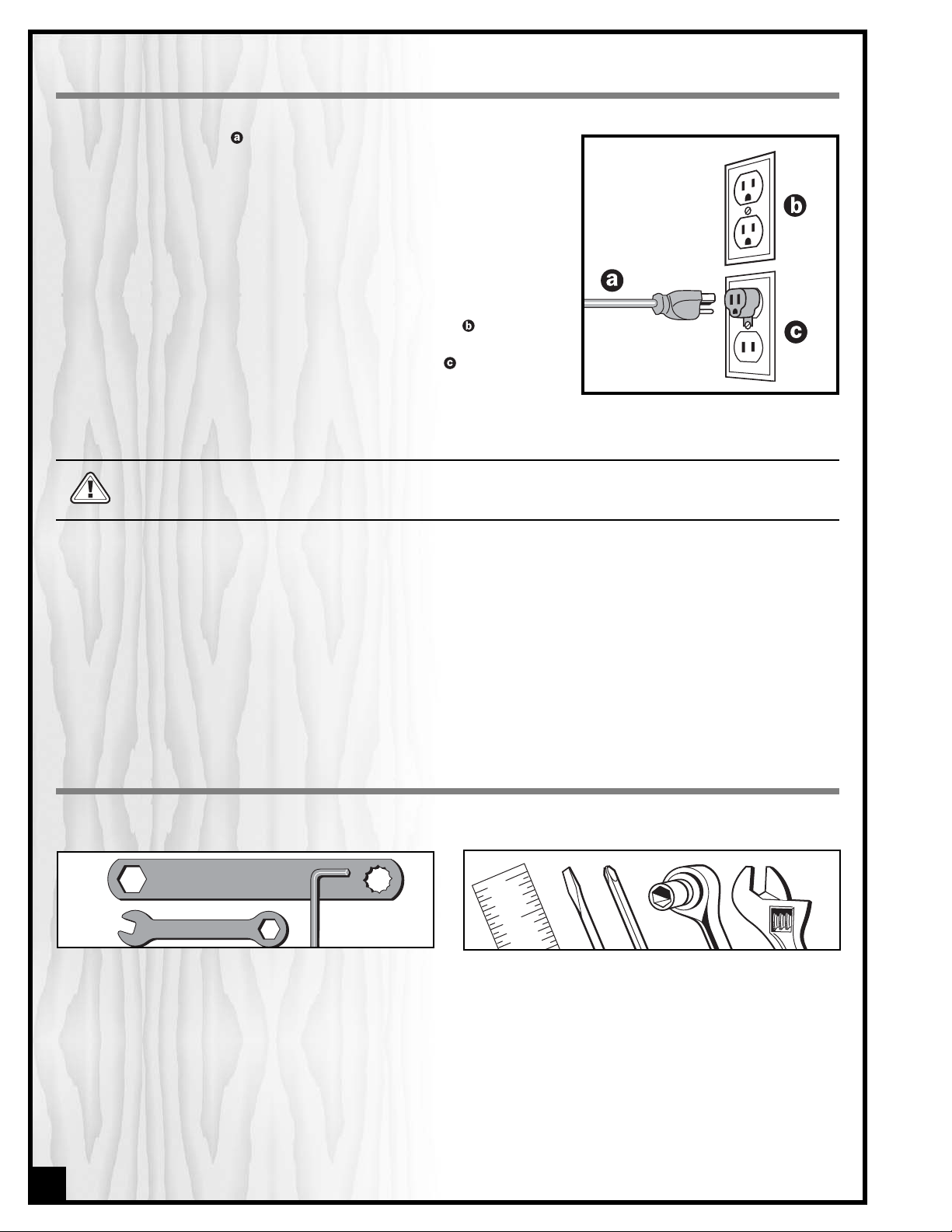
GROUNDING:
This tool must be grounded to protect the operator from
electrical shock. The supplied motor recommended for your saw is
wired for 110 Volt, single phase, and has a 3-conductor cord and 3prong grounded plug to fit a grounded-type receptacle . Do not
remove the 3rd prong (grounding pin) from the plug to make it fit into
an old 2-hole wall socket. If an adapter plug is used it must be
attached to the metal screw of the receptacle.
Note: Use of an adaptor plug is illegal in some areas. Check your
local codes.
Before connecting the motor to the power line, make sure that the switch is in the OFF position and that the
electrical current is of the same type as that stamped on the motor nameplate. All electrical connections
should have proper contact. Running on low voltage will damage the motor.
CONVERTING THE MOTOR TO 220V
Should you need to convert your machine's motor from 110V to 220V power, there is an electrical schematic drawing on the inside of the motor cover plate. For safety reasons, however, we do not supply instructions for conversion.
Unless you are a qualified electrician,we do not recommend attempting this conversion on your own. If you choose
to do so, you may risk personal injury, damage to the motor, and/or the voiding of our warranty.
We suggest you ask your local General International distributor to recommend qualified electricians in your area
(or perhaps one of their own technicians) who can make this conversion properly and safely.
4
UNPACKING & SET UP
ADDITIONAL TOOLS NEEDED
• Straightedge
• Large slot and large Phillips screwdrivers
• Socket wrench (recommended)
• Adjustable wrench
ASSEMBLY TOOLS PROVIDED
• Arbor blade guard bracket wrench
•12 mm combination wrench
• Allen wrench
Page 5
10” DELUXE BUILDER’S TABLE SAW
50-070
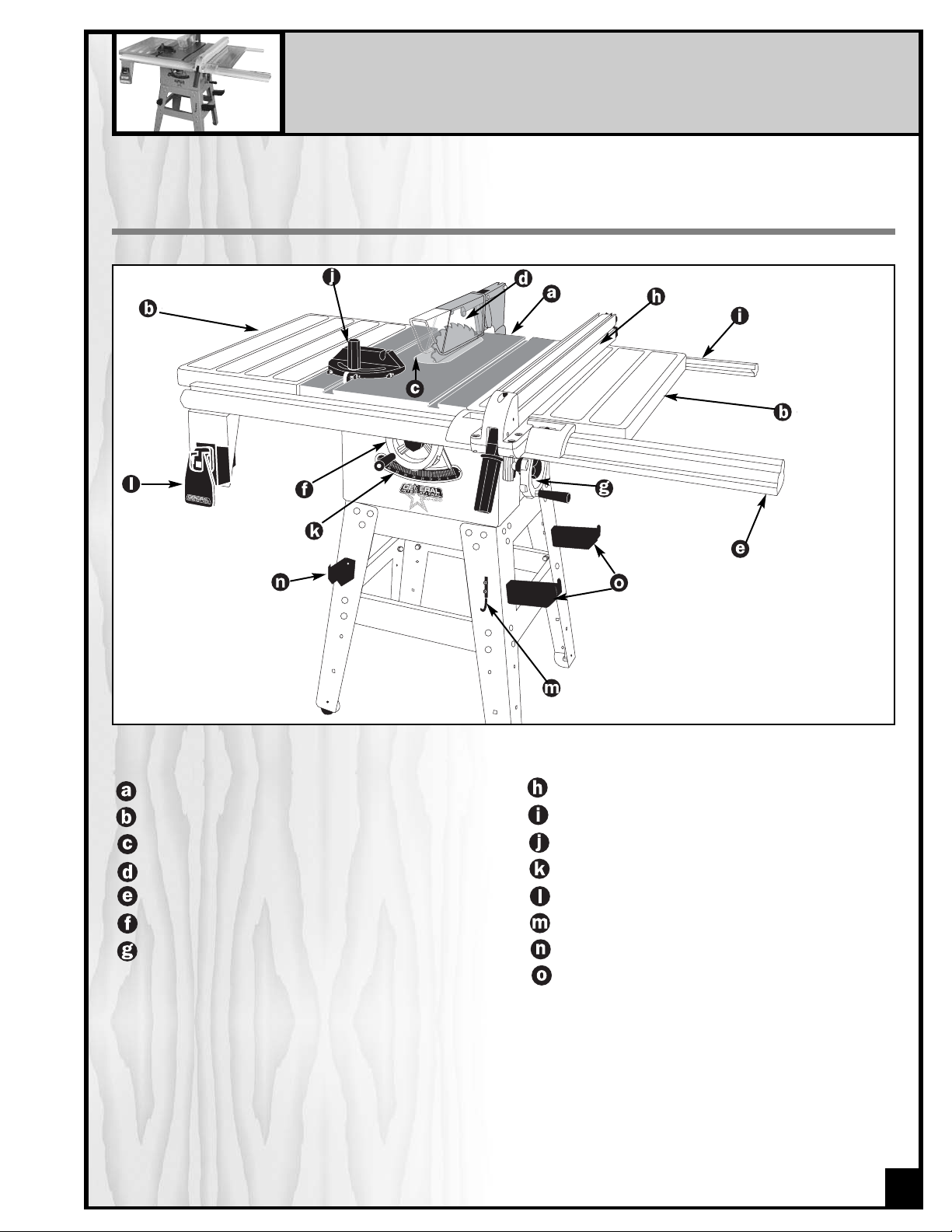
IDENTIFICATION OF MAIN PARTS AND COMPONENTS
MAIN TABLE
STEEL EXTENSION WING
TABLE INSERT
BLADE GUARD/SPLITTER ASS’Y
FRONT GUIDE RAIL
BLADE HEIGHT ADJUSTMENT HANDWHEEL
BLADE TILTING HANDWHEEL
RIP FENCE
REAR GUIDE RAIL
MITER GAUGE
BEVEL SCALE
ON/OFF SWITCH
TOOL HOOK
MITER GAUGE STORAGE MOUNT
FENCE STORAGE MOUNTS
5
STOP
Page 6
ASSEMBLY INSTRUCTIONS
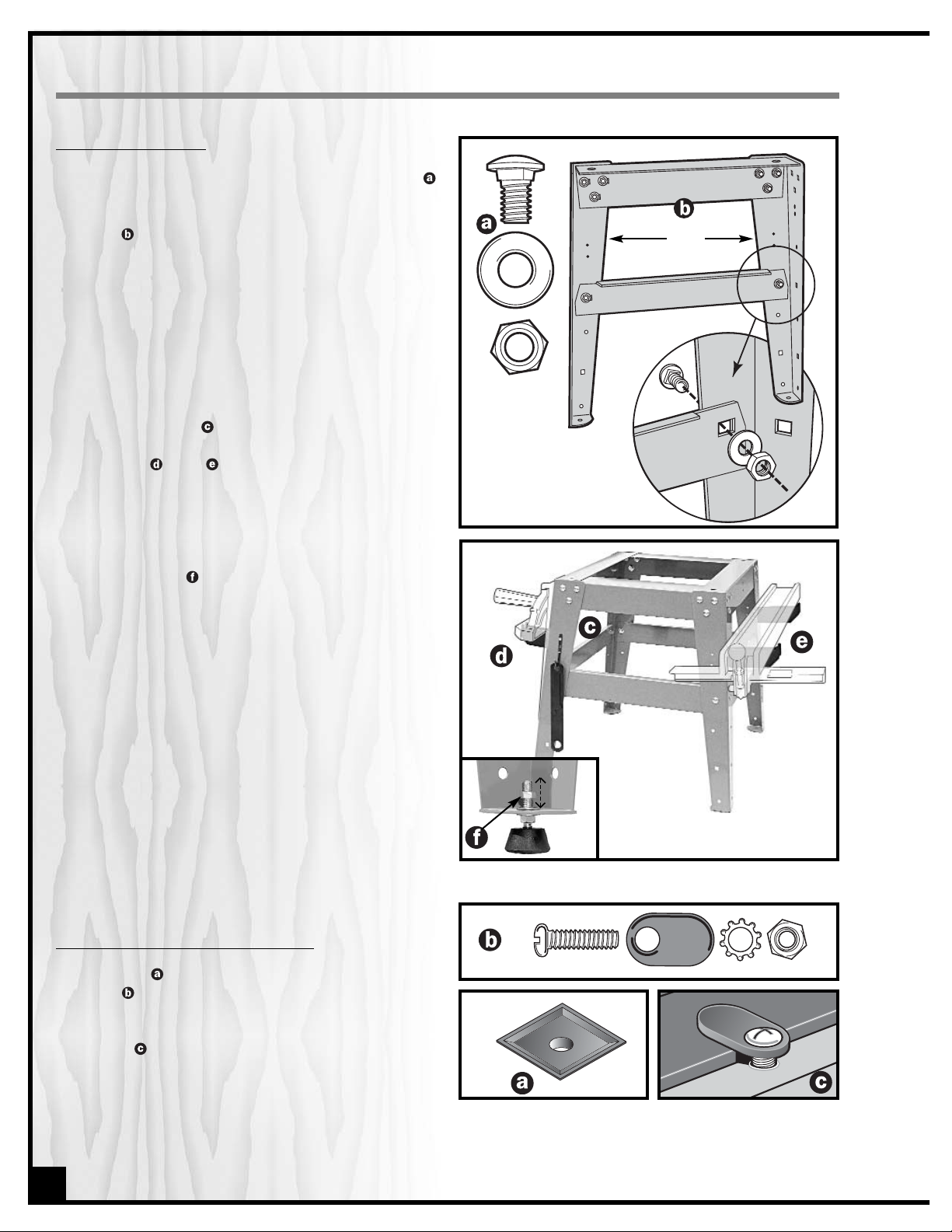
ASSEMBLE THE STAND
1. With the 32 carriage bolts, washers and hex nuts
begin assembling one end of the saw stand by
attaching 1 short top shelf and 1 short tie bar to 2
legs .
Note: Do not tighten hex nuts until all fasteners are
attached. Place the stand on a flat surface to square
it up and finally tighten all the nuts.
2. Assemble the opposite side of the stand the same
way as described in step 1. Then use the 2 long top
shelves and 2 long tie bars to join both assembled
ends and complete the stand.
3. Fasten tool hook to front (use one screw) or either
long top shelf (use both screws) of stand. Fasten
brackets and (for stowing miter gauge and
fence when not in use) to long sides of stand.
4. Attach the 4 rubber feet to saw stand using 2 hex
nuts and 2 washers. After fully-assembled saw is
placed in its final location, level the feet by loosening the top nut ,adjusting lower nut up or down on
the screw stem as needed, then tightening down the
top nut.
Note: If you will be using the mobile base (50-025), do
not attach rubber feet. Fasten the stand directly to
the mobile base.
ATTACH THE DUST COLLECTION TRAY
The dust tray is affixed to the saw stand top with the
fasteners using the two holes in the stand top. ldeally,
a dust collector hose would be clamped to the spout in
the center of the tray. Otherwise, periodically turn the
swivel tabs to remove and empty the tray well before
the sawdust reaches the saw blade and motor.
Short top shelf
Legs
Short tie bar
(Be sure to attach all hori-
zontal shelves and tie bars
to the insides of stand legs.)
6
Fig. 1
Fig. 2
Page 7
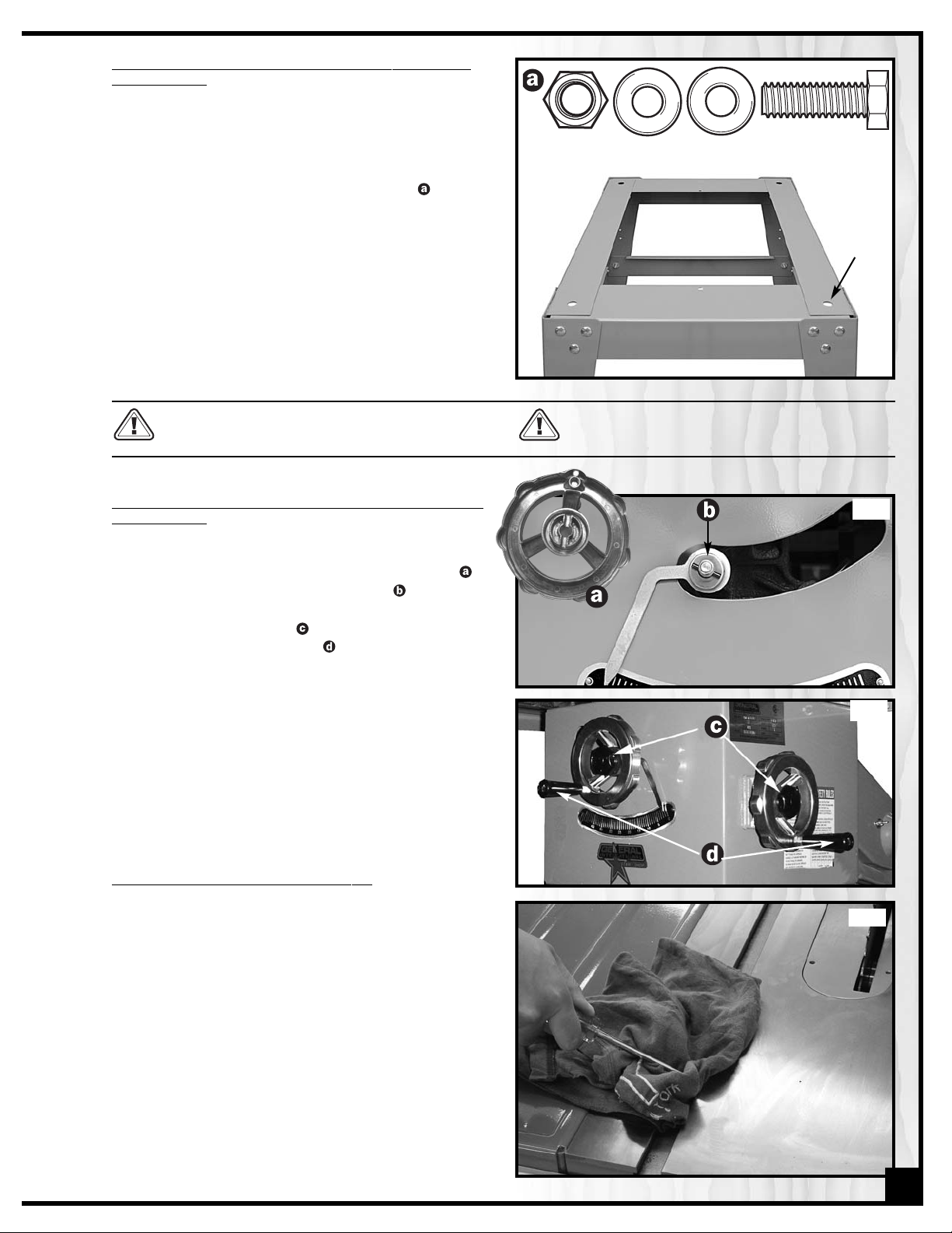
FASTEN THE SAW TO THE STAND OR TO YOUR SHOPMADE BENCH
1. Place the saw onto the stand with its front end along
one of the stand's shorter ends and align the four
holes in the stand's top shelf with those in the saw
base. Fasten saw to stand using the 4 hex head
screws, 4 nuts and 8 washers supplied with the
stand.
2. If the saw is to be used without our supplied stand,
use the four holes on the bottom ledge of the saw
cabinet to fasten the saw to your supporting surface.
Drill corresponding holes into your shop-built stand.
(Or carefully position the saw upon your bench and
with a pencil trace the four holes onto the stand surface) Drill the holes with a 7/16 bit.
ASSEMBLE
THE RAISING & TILTING HANDWHEELS AND
LOCK KNOBS
1. Place the wheels in position over the raising and tilting screws, being sure to engage the slots in
back of each wheel with the rollpins . (See Fig. 4)
2. Screw on lock knobs to hold wheels in place,
then attach silver handles (See Fig. 5) tightening
them with the supplied 12 mm combination wrench.
3. To use raising and tilting wheels, loosen lock nuts
(but not too much or rollpins will disengage from
slots), turn wheels to desired position and retighten
lock nuts. Do not operate saw with lock nuts untightened as the blade could move out of position.
REMO
VE GREASE FROM THE SAW TOP
The protective coating on the saw table top prevents rust
from forming during shipping and storage. Remove it by
rubbing with a rag dipped in kerosene, mineral spirits or
paint thinner. (Dispose of potentially flammable solventsoaked rags according to manufacturer's safety recommendations.) A putty knife, held flat to avoid scratching
the surface, may also be used to scrape off the coating
followed by clean-up with solvent. Avoid rubbing the
saw's painted surfaces, as many solvent-based products
will remove paint.
Suggestion: With a screw driver, push a solvent-saturated
rag into the T-slots (See Fig. 6) to remove the grease so
the miter gauge will slide freely.
A cutout hole must be provided in your wood
stand or bench for sawdust removal.
Secure your stand or bench to floor if during use
there is any tendency for the saw to tip over, slide
or crawl.
(back view
of wheel)
7
7/16”
diam.
holes
Fig. 3
Fig. 4
Fig. 5
Fig. 6
Page 8
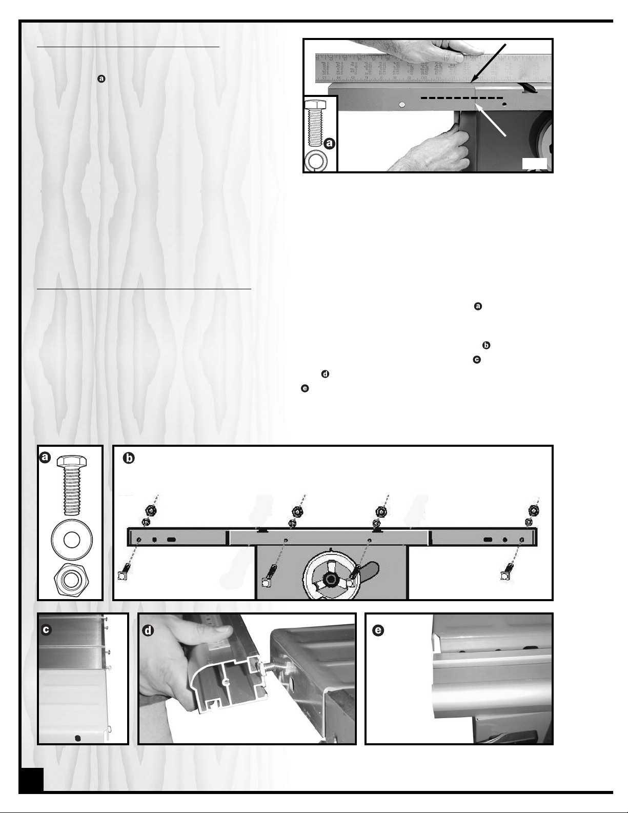
ASSEMBLE THE STEEL EXTENSION WINGS
Attach extension wings using the 6 hex head screws and
lock washers .Make screws only finger tight at first. Use
a straightedge to ensure that wing is level with table
from front to back. Gently tap wing up or down, then
tighten screws with the supplied combination wrench,
leaving the center screw to be tightened last.
Be sure that extension wings are flush with front edge of
table.(See Fig. 7)
level here
flush here
ASSEMBLE THE FRONT FENCE RAIL/GUIDE TUBE
Using 4 square head bolts (2 short bolts & 2 long) with their corresponding flat washers & hex. nuts , install the bolts
to the front of the table as follows:
1. Insert 1 short bolt into each steel extension & 2 long bolts into the main table, as shown below .
2. Do not tighten down the nuts. Leave the square heads of the bolts protruding from the table .
3. Slide the upper slot of the rail onto the square head bolts until all 4 bolts are in the slot and the left end of
the rail is aligned with the edge of the extension wing .
4. Tighten down the nuts to firmly secure the rail to the table.
8
Fig. 7
Page 9

MOUNT THE SWITCH
1. Fit the head of the bolts into the slot in the underside of the rail.
2. Assemble the On/Off switch in the two holes in the switch bracket (leave the center hole free) on the left side of
the rail using the supplied hex nuts and washers . (See Fig. 8) Install the end caps at each end of the rail.
(See Fig. 9)
ATTACH THE REAR FENCE RAIL
Using 4 square head bolts (2 short bolts & 2 long) with their corresponding flat washers & hex. nuts, install the bolts
to the rear of the table as follows:
1. Insert 1 short bolt into each steel extension & 2 long bolts into the main table .
2. Do not tighten down the nuts, leave the square heads of the bolts protruding from the table.
3. Slide the rail onto the bolts as shown , until all 4 bolts are in the slot and the left end of the rail is aligned with
the edge of the extension wing.
4. Tighten down the nuts to firmly secure the rail to the table. Install the end caps at each end of the rail.
LEVEL THE TABLE INSERT
Place the insert into the table and use a straightedge to
determine whether the insert is level with the table top.
Turn each of the 4 adjusting screws with the supplied
Allen wrench until done. (See Fig. 10)
Suggestion: Start by adjusting 1 rear screw and its diagonal opposite in front, then tweak the remaining 2
screws.
Note: If the sawblade has already been installed, use
the raising handwheel to lower the blade below the
table surface before leveling the insert.
9
Fig. 8
Fig. 9
Fig. 10
Page 10

INSTALL A SAW BLADE
1. Remove the table insert by pulling with your finger in the hole . Use
the supplied arbor wrench turning it counter-clockwise to remove
the arbor nut and flange . (See Fig. 11)
2. Install a saw blade (not supplied with the saw) so that the openings
between the teeth face the front of the saw (the blade spins in the
counter-clockwise direction).
3. Replace the flange and arbor nut. Wedge a board between the saw
teeth at the back of the saw (See Fig. 12) so the blade won't turn as you
tighten the nut clockwise with the arbor wrench.
Remove a saw blade:
wedge a block of wood between the teeth in front
of the saw and turn the arbor wrench toward you, or counter-clockwise.
Be sure the saw is disconnected from the power source whenever
installing or removing a saw blade!
INSTALL TAPE MEASURE ON FRONT RAIL
1. Raise the blade 1"- 2" above the table, move the fence to lightly touch the right side of the blade and lock the
fence in place. (See Fig. 13)
2. Using a pencil, make a light reference line on the top of the rail in-line with the screw hole for the fence pointer.
(See Fig. 14)
3. Remove the fence and stick the right hand (long) adhesive tape measure to the rail, roughly lining the zero
point on the tape with your reference line on the rail. (See Fig. 15)
4. To Install the left hand tape, repeat the same steps but to the left of the blade.
Install the pointer on the fence either to the left or right as needed (See Fig.
16). Do not fully tighten the pointer screw just yet. With the fence locked in
place against the blade, line the reference line up on the pointer with the
zero point on the tape and now tighten the pointer screw.
Note: When changing blades realign the pointer with the zero point on
the tape, to account for thinner or thicker blade widths.
10
Fig. 11
Fig. 12
Fig. 13
Fig. 14
Fig. 15
Fig. 16
Page 11

ASSEMBLE MOTOR, MOTOR PLATE & BELT GUARD PLATE
1. Attach the motor mounting plate to the mounting
bracket by inserting the rod . Make sure the
v-groove in the rod is under the screw. Tighten the
screw into the v-groove. (See Fig. 17)
2. Attach the assembled motor mounting plate and
motor bracket to the saw: Slide the motor bracket as
far back as possible onto the two posts , making
sure both posts protrude equally from the bracket.
3. Tighten both set screws well with the Allen wrench.
(See Fig. 18)
Note: If necessary, before you slide the bracket on,
use the supplied Allen wrench to slightly raise the set
screws so they don't obstruct the post holes.
PREPARE THE PULLEY GUARD FOR MOUNTING
Assemble a screw, washer and metal bushing to the
pulley guard bracket . Snap the c-clip onto the
screw (squeeze it on with pliars, if necessary) and fingerturn it tight against the bushing as shown in the detail .
(See Fig. 19) This will keep the screw firmly perpendicular
to the plate for later when the belt guard cover will be
attached.
MOUNT THE MOTOR AND PULLEY GUARD ONTO THE SAW
1. Place the pulley guard that you just assembled and
the fasteners within easy reach. Lift the motor onto
the motor plate. (It will be helpful to sit facing the
saw with the motor plate on your knees (put a board
under the motor plate if the weight hurts your
knees). (See Fig. 20)
2. Attach the fasteners in the order shown through
the 4 slots on the motor and motor mounting plate.
Leave the fasteners loose. Don't wrench-tighten
them yet!
3. With the motor mounting plate and motor still raised
on your knees to about level, lift the motor just
enough to slide the pulley guard bracket,
between it and the motor plate so the guard bracket's slots straddle the fasteners .
Push the pulley guard in to about 1/2” away from
the motor. (See Fig. 21)
The following may well be the most challenging
part of your assembly. Proceed with patience.
1/2”
Fig. 17
Fig. 18
Fig. 19
Fig. 20
Fig. 21
11
Page 12

4. Slide the motor base and pulley guard bracket
around so both the front edges are aligned fairly
straight with the front of the motor mounting plate.
The long vertical side of the pulley guard should be
relatively parallel to the side of the motor. (See Fig.
22)
For now, wrench-tighten only the two nuts in front
(in case you have to loosen them again to reposition the motor and/or pulley guard).
5. Put the v-belt on the pulley arbors.
Crucial to success:
The pulleys must be aligned so
the belt doesn't pop off or wear unevenly during
use, and the pulley guard bracket must be parallel
with, but not rubbing against the belt, or against the
pulley cover during operation.
6. Lower the motor so it is suspended by the v-belt. Test
your alignment by placing a ruler or straightedge
against the pulley arbors. (See Fig. 23) Ideally, the
straightedge should line up flush against the arbor
as shown in the inset . At this time, hold the pulley
cover temporarily in place to make sure the belt is
not rubbing against it.
If either the pulley arbors or pulley guard bracket
are not aligned properly, loosen one or both of the
tightened nuts just enough to be able to push the
motor or pulley guard into a better arrangement.
Make adjustments as needed then finally tighten all
4 nuts.
7. Attach the pulley cover . Place the pulley cover so
the screw protrudes through the hole and affix the
cover with the red washer, then silver washer and
wing nut . (See Fig. 24)
ADJUST
THE 45° AND 90° POSITIVE STOPS & SETTING
THE POINTER
Your saw has preset accurate stops at 45° and 90°.
However, the pointer may sometimes require adjustment.
1. Raise the blade to its maximum. Set it at 90° by turning the tilt handwheel clockwise as far as it will go.
2. Place an L-square or triangle square on the
table to check that the blade is at a perfect 90°
angle to the table. Be sure to position the square
between the teeth so it is in contact with the blade
itself and not the set of the teeth.(See Fig. 25)
3. If the blade is not at 90°, loosen lock nut and turn
adjusting stop screw in or out. The adjusting stop
screw should stop against the end of the tilting screw
when the blade is at 90° to the table. Re-check
and adjust further if necessary. (See Fig. 26)
4. If the 45° positive stop is not set properly, follow the
same procedure using screw and nut .
12
Fig. 22
Fig. 23
Fig. 24
Fig. 25
Fig. 26
Page 13

5. Check the pointer on the front of the saw. If it does
not point exactly to 90° on the pointer gauge,
remove the raising handwheel, loosen the set screw,
(See Fig. 27)and turn the pointer so it points to 90°
on the gauge. Re-tighten the set screw and replace
the handwheel.
ADJUST THE RAISING MECHANISM FOR "WEAR"
After a long period of time, it is possible that the raising worm and the teeth on the arbor bracket will wear slightly
resulting in play in the raising mechanism.To compensate,the raising worm and arbor bracket can be brought closer together as follows:
1. Remove the lock knob and raising handwheel, but don't remove the pointer .
2. Loosen the lock nut and using the pointer as a lever, turn to the right or left until all perceptible play is
removed.
3. Reset the pointer to 0° degree and tighten the lock nut.
4. If mechanism is too tight, reverse the above procedure
ASSEMBLE
THE BLADE GUARD AND SPLITTER
1. Screw the splitter support rod into the back of the saw. Grip the rod with a wrench at its midsection indents
to tighten it .
2. Slide the splitter mounting bracket, below onto the support rod.
3. Lower the splitter , the back leg straddles the 2 hex head bolts on the left side of the mounting bracket. Tighten those 2 bolts.Tighten the bottom 2 bolts that secure the bracket to the rod.
4. To avoid kickback or binding, the blade must be aligned with the splitter. Place a straightedge on the blade
. Loosen the lower 2 bolts to slide the top part of the bracket left/right until the splitter is aligned. Tighten the
bolts.
13
Fig. 27
Page 14

OPERATING INSTRUCTIONS
RIPPING
Cutting a wood plank or sheet of plywood lengthwise to
reduce its width is called "ripping". To rip stock, hold the
work with both hands pushing it into the blade as well as
firmly against the rip fence so that it is cut straight. (See
Fig. 28)
• The work to be cut must have a straight edge to ride
the fence and must be flat to make solid contact
with the table during the cut in order to avoid "kickback" (a blade jam causing the wood to fly backwards and hit the user).
• Never rip or cut wood without using the fence or
miter gauge to guide it because the stock could
kickback.
• Always use the blade guard and splitter assembly
when cutting wood. It has anti-kickback fingers and
a splitter to prevent the saw "kerf" (the slit cut by the
blade) from closing and binding the blade, which
can overload and/or stall the motor. The blade
guard keeps your fingers away from the blade and
also reduces the amount of sawdust flying free.
• Although certain operations require the removal of
the blade guard and splitter assembly, it should
always be replaced for regular cutting.
• Never stand in the line of the blade when ripping.
• Raise the saw blade about 1/4” higher than the work to be cut.
As you complete the rip, the wood will either remain on the table, tilt up to be caught on the end of the guard, or
fall onto the floor (or outfeed table). The waste part of the stock remains on the table to be removed only after the
saw is stopped (unless it is large enough for immediate safe removal).
If the work to be ripped is narrow, it is safer to use a push stick, rather than the hands, to feed it into the blade. Push
sticks with non-slip grippers can be purchased, but a shop-made one works just as well. (See Fig. 29)
When ripping extremely narrow stock that may not clear the width of the blade guard, or very thin material such as
paneling, which may slip between the underside of the fence and the table surface, a strip of wood as an auxiliary
guide can be attached to the fence.
CR
OSSCUTTING
Cutting against the grain, to shorten the length of a board is “cross-cutting”. With some smaller-sized and rectangular pieces, you often have the choice of ripping or crosscutting. Always use the miter gauge when crosscutting;
never cut a piece unsupported. (See Fig. 30) The miter gauge may be used in either slot, but most operators prefer
the left groove for typical work. When the blade is tilted for bevel cutting, use the table slot that does not cause interference with your hand or the saw blade guard.
To begin crosscutting, place the work on the miter
gauge and, with the motor OFF, slide it up close to the
blade to align the outer edges of the teeth with your cut
mark (See Fig. 31). Keep a firm grip as you pull the miter
gauge and the wood back away from the blade. Lower
the blade guard, turn on the saw and make the cut.
When the work is cut through, move one or both cut
pieces—if long enough to handle without danger—
immediately off to the side, away from the turning blade.
Turn off the motor.
14
Fig. 28
Fig. 29
Fig. 30
Fig. 31
Page 15

USING THE MITER GAUGE
The miter gauge supplied with your saw has accurately adjusted
index stops at 90° and 45° to the right and left, with a 30° maximum.
To use a setting other than 90°, loosen the lock knob by turning it
counter-clockwise, flip down the stop-lock tab , rotate the miter
head to 45°, or any angle shown on the scale. Turn the lock knob
clockwise to tighten it. (See Fig. 32)
To check the accuracy of the miter gauge's factory settings, set it at
90° and check it with an L-square or T-square. To verify the setting,
make a test cut in scrap stock and then use a square to check the
cut piece. Repeat adjustment if necessary.
If the miter gauge needs adjusting, manually turn the head so the
pointer is where you think it ought to be, tighten the lock knob and
loosen the nut . (See Fig. 31) Turn the adjusting screw until it touches the stop-lock tab. Tighten down the nut again. Recheck the angle
by making another test cut. Repeat, if necessary, until a true 90° is
achieved.
ADDING
AN AUXILIARY FENCE TO THE MITER GAUGE
To ensure a true 90° crosscut, especially with longer pieces of wood
that need more support than the narrow miter gauge head can provide, an auxiliary wood fence can be attached.
Make sure the wood for the fence is straight, not bowed. It should be
about 2” wide and extend about 12” from either side of the miter
head. Drill 2 holes in the wood corresponding to those on the miter
head and use bolts and nuts to secure the wood fence to the head
. (See Fig. 34)
To use the miter gauge with an auxiliary fence, first notch the fence
with the saw blade a bit higher than the work-piece . Measure and
draw an outline on your wood and then place it on the miter
fence. Position your outline against the notch. Turn on the saw, slide
the work up until it is cut through (but don't cut off the fence).
Marking Wood. If you measure a cut for 24”, line up the blade on the waste side of the mark. Don't cut through the
middle of the measurement line or you'll reduce your desired board length by half the width of the saw blade! For
accurate work, don't mark your cut with a fat pencil line . A narrow dash, with a sharp pencil point is best
. Encircle the dash so you'll find it again and add a small X to indicate the waste or cut-off side. (See Fig. 35)
Pencils, like saw blades, have thickness. When squaring off from the cut mark, align your square to allow for pencil
clearance, which will be about 1/16" away from the drawing edge of the square
. (See Fig. 36, 37)
15
Fig. 32
Fig. 33
Fig. 34
Fig. 35
Fig. 36
Fig. 37
Page 16

RECOMMENDED OPTIONAL ACCESSORIES FOR YOUR SAW
We offer a large variety of products to help you increase productivity, accuracy and safety when
using your saw. Here’s a small sampling of accessories available from your local General
International dealer. For a complete list, visit our website at www.general.ca.
Safety kit model 99-400
Includes 2 push sticks, 1
rubber based push
block and a solid oak
featherboard for safer
stock feeding and
handling.
Tenoning Jig
model 50-050
Solid cast iron. Fits left or
right tilt saws for safe and
accurate tenoning.
Mobile base
model 50-025
Easily roll your table saw
anywhere in your shop.
Load capacity: 500 lbs.
Wheels lock when
equipment is in use.
Zero Clearance insert
model 50-065
Eliminates space between
the blade and insert to
help reduce tear-out and
airborne dust. Raise the
blade through the insert
and custom cut to your
blade kerf.
Dust Collector
We have a wide selection
of dust collectors to suit all
your shop needs. Dust
collectors contribute to a
cleaner and more
healthful workshop
environment.
16
USING A DADO HEAD BLADE
Dadoing is cutting a “rabbet” or a wide groove into the work. A
dado blade, , (not supplied with your saw) usually consists of two
outer blades and several interior cutters. These can be adjusted to
cut grooves from 1/8” to 13/16”for making shelves,joints and tenoning. Set the blade’s width according to the instructions.
After adjusting its width, mount the dado blade on your saw just like
a regular blade. You’ll need an optional dado insert, , (#50070001A) to replace the standard one that comes with your saw. Use
the fence to line up the cut. The blade guard/splitter must be
removed when dadoing. Never use the dado blade in a bevel position.
Electronic Earmuffs
99-200
Highly efficient noise
reduction to help protect
your hearing when
operating power tools.
Page 17

87
6
31A
91
88
93
155
155
87B
85
3
82
11
90
99
102
7
160
159
156
45
103
88
107
82
104
112
118
116
114
110
109
91
31A
6
125
3
130
131
116
6
16
122
93
120
108
3
136
132
6
118
140
124
7
154
66
151
146
148
138
81
80
81
80
81A
158
81B
45
82
87A
3
83
11
81A
111
94
66
95
97
119
81B
128
162
31A
142
149
85
3
45
155
155
178
81B
81C
81C
17
Page 18

71B
78
73
16
6
12
11
11A
5
13
7
6A
6
10
69
76
68
72
70
66
67
4
1
95
61
88
41
57
195
41
191
42
191
48
47
40
16
7
132
65
6
16
48
64
31A
6
31A
6
132
6
192
192
193
194
196
187
141
14
21
21D
21B
21A
79B
142A
8
71A
10
3
2
79C
79B
79E
12
11A
11
66
79F
21C
79D
79G
79I
79A
79B
18
Page 19

PARTS LIST
50-070
PART NO. REF.NO. DESCRIPTION SPECIFICATION QTY
50070-001 10101001A TABLE INSERT 1
50070-002 10101002 BUMPER 1
50070-003 S0050404 SOCKET SET SCREW 1/4"-20UNCx1/4" 10
50070-004 10201002A TABLE 1
50070-005 10201003 CABINET 1
50070-006 S0210500C WASHER 5/16" -18X2T 26
50070-006A S0020500 SPRING WASHER 5/16" 4
50070-007 S0020510 HEX HD. SCREW 5/16"-18UNCx5/8" 9
50070-008 J1000002 LABEL 1
50070-010 E0000008 STEEL EXTENSION WING 2
50070-011 S0210623 FLAT WASHER 3/8"X23X2T 8
50070-011A S0230308 SPRING WASHER 3/8" 6
50070-012 S0020712 HEX HD. SCREW 3/8"-16UNCx1" 6
50070-013 10101007 BEARING BRACKET 1
50070-014 S0090512 RD. HD. SCREW 5/16"-18UNCx3/4" 2
50070-016 S0110500 HEX NUT 5/16"-18UNC 54
50070-21 10201010 DUST COVER 1
50070-21A 30203019A LOCK PLATE 2
50070-21B S0220300 SPRING WASHER 3/16:" 2
50070-21C S0110400 HEX NUT 1/4"-20UNC 9
50070-21D S0030306 RD. HD. SCREW 3/16"-24UNCX5/8" 2
50070-031 S0210500 WASHER 5/16"X16X1T 40
50070-031A S0230506 SPRING WASHER 12
50070-040 10103045 BLADE GUARD 1
50070-041 10103039Q ANTI-KICKBACK 2
50070-042 11103040 SPRING 1
50070-045 S0310525 SPRING PIN 5X25 3
50070-047 10103046 SUPPORTING ARM 1
50070-048 S0120200 LOCK NUT 1/4"-20UNC 2
50070-057 10103038N SPLITTER 1
50070-061 10801005 BRACKET ARBOR 1
50070-064 10403020 BRACKET 1
50070-065 10403019 BRACKET 1
50070-066 S0210400 WASHER 1/4" 14
50070-067 10104045 HAND KNOB 1
50070-068 S0110100 HEX NUT 5/32"-32UNC 3
50070-069 S0030108 RD. HD. SCREW 5/32"-32UNCX1/2" 3
50070-070 10104046 MITER GAUGE BODY 1
50070-071A 10104047 SLIDING BLOCK 1
50070-071B S0040400 FLAT HD.SCREW 1/4"-20UNCX1/4" 1
50070-072 10104048T GUIDE BAR 1
50070-073 10104049 LOCATING PLATE 1
50070-076 10104050 POINTER 1
50070-078 S0310306 SPRING PIN 1
50070-079 W0000000 SWITCH ASS'Y 1
50070-079A S0030324 RD. HD. SCREW 3/16"-24UNCX1-1/2" 4
50070-079B S0110300 HEX NUT 3/16"-24UNC 14
50070-079C 10105052N SWITCH PROTECTION BOX 1
50070-079D 10105053G SWITCH FIXING PLATE 1
50070-079E 50000112 HEX HD. SCREW 1/4"-20UNCX1" 2
50070-079F S0230400 FLAT WASHER 1/4" 2
50070-079G W00000007 SWITCH 1
50070-079I W0000012 PIN LOCKING(SWITCH) 1
50070-080 10105054 KNOB 2
50070-081 10105055 HANDWHEEL 2
19
Page 20

20
PARTS LIST
50-070
PART NO. REF.NO. DESCRIPTION SPECIFICATION QTY
50070-081A 10105056 KNOB 2
50070-081B S0110600 HEX NUT 3
50070-081C RD. HD. SCREW 3/8"-16UNCx3-1/4" 2
50070-082 S0240600A FIBER WASHER 3/8" 4
50070-083 10105057 POINTER 1
50070-085 10105058 SET COLLAR 2
50070-087 10105059 TILT SHAFT 1
50070-087A 10105060 ECCENTRIC 1
50070-087B S0110900 HEX NUT 9/16"-20UNF 1
50070-088 S0313520 SPRING PIN 3.5X20 3
50070-090 10105061 FRONT BRACKET 1
50070-091 S0020520 HEX HEAD SCREW 5/16"-18UNCx1-1/4" 4
50070-093 S0111000 SPECIAL NUT 5/8"-24UNF 2
50070-094 10105062 STOP BLOCK 1
50070-095 S0020420 HEX HEAD SCREW 1/4"-20UNCx1-1/4" 2
50070-097 S0050401 SOCKET SET SCREW 1/4"-20UNCx1" 1
50070-099 10105063 FRONT TRUNNION 1
50070-102 S0253116 SPRING WASHER 1
50070-103 10205024 ECCENTRIC 1
50070-104 10205025 ELEVATING SHAFT 1
50070-107 10105066 SPACER 1
50070-108 10105067 ARBOR BRACKET SHAFT 1
50070-109 10105068A ARBOR NUT 1
50070-110 10105069 FLANGE 1
50070-111 B0000000 COMBINATION BLADE 1
50070-112 10105071 ARBOR BRACKET 1
50070-114 10105072 ARBOR 1
50070-116 C1106203 BEARING 6203ZZ 2
50070-118 S0410525 KEY 5X5X25 2
50070-119 SWW6203 LOADING SPRING 1
50070-120 S0534000 C-RING R40 1
50070-122 10105073FC ARBOR PULLEY 1
50070-124 10105074 REAR TRUNNION 1
50070-125 10105075 REAR TRUNNION BRACKET 1
50070-128 10105076 MOTOR BRACKET 1
50070-130 10105077 MOTOR PLATE ROD 1
50070-131 10105078 MOTOR PLATE 1
50070-132 S0020501 HEX HEAD SCREW 5/16"-18UNCx1" 8
50070-136 10105079F MOTOR PULLEY 1
50070-138 S0410525 BELT 3VX 1
50070-140 M0000000 MOTOR 1
50070-141 L0000000 POWER CORD 1
50070-142 L0000112-1P MOTOR CORD 14AWGx3C 65CM 1
50070-142A L0000111-1P SWITCH CORD 1
50070-146 S0060428 CARRIAGE BOLT 1/4"-20UNCx1-3/4" 1
50070-148 10105084 GUARD PLATE 1
50070-149 S0020412 HEX HD. SCREW 1/4"-20UNC X3/4" 1
50070-151 10105085 GUARD COVER 1
50070-154 10205029 WING NUT 1/4"-20UNC 1
50070-155 S0110501 HEX NUT 5/8"-18UNF 4
50070-156 10205031 TIE ROD 2
50070-158 10105089 SPECIAL SCREW 3/8"-16UNCx2" 1
50070-159 10105090 COMBINATION WRENCH 1
50070-160 10105091 OPEN END WRENCH 1
50070-162 10105092 WRENCH HEX L:3 1
50070-166 10107098G RUBBER FEET 4
Page 21

183
132
173
166
21C
66
184
185
182
186
16
31
66
31
16
79B
167
189
188
190
21C
PARTS LIST
50-070 - STAND
PART NO. REF.NO. DESCRIPTION SPECIFICATION QTY
50070-167 S0030310 RD HD. SCREW 3/16"-24UNCX5/8" 8
50070-173 S0060509 TRUSS HEAD SCREW 5/16"-18UNCx5/8" 32
50070-178 10105086 SPACER 1
50070-182 10206036 FOOT STAND 4
50070-183 10206038 BOTTOM LONG BRACKET 2
50070-184 10206037 BOTTOM SHORT BRACKET 4
50070-185 10206040 TOP SHORT BRACKET 2
50070-186 10206039 TOP LONG BRACKET 2
50070-187 10202017 ROD 1
50070-188 11500044 BALANCING PLATE 1
50070-189 11500045 HOOK 1
50070-190 11500006 BRACKET 2
50070-191 S0140400 LOCK NUT 1/4"-20UNC 2
50070-192 S0710410 RIVET 2
50070-193 11203022 FLAT WASHER 1
50070-194 S0110812 HEX NUT 1/2"-12UNC 1
50070-195 S0040401 FLAT HD.SCREW 1/4"-20UNCX1 1
50070-196 10103047 SPACER 2
STAND
21
Page 22

22
3
4
5
6
7
2
9
25
10
1
23
24
25
15
16
17
18
21
19
25
20
25
25
35
29
26
36
13
14
12
8
25
33
11
39
38
40
40
39
38
43
41
43
42
41
39
34
25
38
43
31
40
42
41
30
28
27
38
40
39
25
32
37
43
42
41
42
PARTS LIST
50-070 - FENCE
PART NO. REF.NO. DESCRIPTION SPECIFICATION QTY
50070-F01 11102014 FENCE HEAD(DOWN) 1
50070-F02 11102013 FENCE HEAD(UP) 1
50070-F03 11102017A HANDLE ASS'Y 1
50070-F03A 11102017B HANDLE SUPPORTER 1
50070-F03B 12100033R HANDLE 1
50070-F04 S05ETW06 E-RING 2
50070-F05 11102015A LOCK SPINDLE 1
50070-F06 11102015 ROTATION PLUG 1
50070-F07 11102018 HOLDING PIECE 1
50070-F08 S0310843 PIN 8X43 2
50070-F09 S0010500 CAP SCREW 5/16"-18UNCX1/2" 4
50070-F10 11102016 CONNECTING PLATE 1
50070-F11 S00104012 CAP SCREW 1/4"-20UNCX3/4" 4
50070-F12 11102011 CLAMP BLOCK 2
50070-F13 11102012 FRONT SPACER 2
50070-F14 S0070302 SELF TAPPING SCREW 5/32"-32UNCX3/8" 4
50070-F15 11102027A FENCE 1
50070-F16 11102028A ROD 1
50070-F17 11102032 SPRING PLATE 1
50070-F18 11102031 CLAMPING PLATE 1
50070-F19 11102030 HOLDER 1
50070-F20 11102029 REAR PROTECTION COVER 1
50070-F21 S0120200A NYLON NUT l/4"-20UNC 1
50070-F23 11102022 CLEAR INDICATOR 1
50070-F24 S0210300B FLAT WASHER 4.3X10X1T 1
FENCE
Page 23

PARTS LIST
50-070 - FENCE
PART NO. REF.NO. DESCRIPTION SPECIFICATION QTY
50070-F25 S0070203 SELF TAPPING SCREW 5/32"-32UNCX1/2" 8
50070-F26 11101005R FRONT RAIL(LONG) 1
50070-F27 11101005L FRONT RAIL(SHORT) 1
50070-F28 11101008 FRONT RAIL CONNECTOR 1
50070-F29 11102006R REAR RAIL(LONG) 1
50070-F30 11102006L REAR RAIL(SHORT) 1
50070-F31 11101013 REAR RAIL CONNECTOR 1
50070-F32 11101009 FRONT RAIL CAP(LEFT) 1
50070-F33 11101010 FRONT RAIL CAP(RIGHT) 1
50070-F34 11101011 REAR RAIL CAP(LEFT) 1
50070-F35 11101012 REAR RAIL CAP(RIGHT) 1
50070-F36 J1110014 SCALE 24" 1
50070-F37 J1110015 SCALE 12" 1
50070-F38 11102033 SQUARE HEAD BOLT 5/16"-18UNCX1" 1
50070-F39 S0210516 FLAT WASHER 5/16X16X2T 4
50070-F40 S0110500 NUT 5/16"-18UNC 4
50070-F41 11103013 SQUARE HEAD BOLT M6XP1.0X32L 4
50070-F42 S0210403 FLAT WASHER 1/4X16X2T 4
50070-F43 S0110600M NUT M6XP1.0 4
NOTES
23
Page 24

IMPORTANT: When ordering replacement parts, always give the model number, serial number of
the machine and part number. Also a brief description of each item and quantity
desired.
STOP
50-070
8360, Champ-d’Eau, Montreal (Quebec)
Canada H1P 1Y3
Tel.: (514) 326-1161
Fax : (514) 326-5565
Parts & Service
Fax : (514) 326-5555 Order Desk
orderdesk@general.ca
www.general.ca
 Loading...