

Page 1
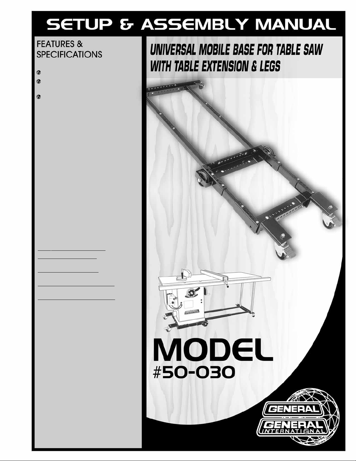
2 HEAVY DUTY 4”WHEELS.
2 HEAVY DUTY 3”CASTERS WITH LOCK-
ING LEVERS.
2 SWIVEL CASTERS.
C
AP
ACITY 900 LBS (410 KG)
MINIMUM SQUARE SIZES
19-1/2”x 19-1/2” (495 x 495 mm)
MAXIMUM SQU
ARE SIZES
24-3/4”x 24-3/4” (629 x 629 mm)
MIMIMUM RECT
ANGULAR SIZES
17”x 19-1/2” (432 x 495 mm)
MAXIMUM RECT
ANGULAR SIZES
24-3/4”x 27-1/2” (629 x 699 mm)
REVISION 1 APR 07/06
Page 2

THANK YOU
for choosing this General® International model 50-030 Mobile Base.
This mobile base has been carefully tested and inspected before shipment and if properly
used and maintained, will provide you with years of reliable service. To ensure optimum performance and trouble-free operation, and to get the most from your investment, please take
the time to read this manual before assembling,ins talling and operating the unit.
The manual’s purpose is to familiarize you with the safe operation,basic function,and features
of this mobile base as well as the set-up,maintenance and identification of its parts and components. This manual is not intended as a substitute for formal woodworking instruction, nor to
offer the user instruction in the craft of woodworking. If you are not sure about the safety of
performing a certain operation or procedure, do not proceed until you can confirm, from
knowledgeable and qualified sources,tha t it is safe to do so.
Once you’ve read through these instructions, keep this manual handy for future reference.
All component parts of General® International machinery are carefully tested and inspected during all s tages of
production, and each unit is thoroughly inspected upon completion of assembly. Because of our commitment to
quality and customer satisfaction, General® International agrees to repair or replace, within a period of 24 months
from date of purchase,any genuine part or parts w hich, upon examination,prove to be defective in workmanship
or material. In order to obtain this warranty, all defective parts must be returned freight pre-paid to General®
International Mfg. Co., Ltd. Repairs attempted without our written authorization will void this warranty.
GENERAL ® INTERNATIONAL WARRANTY
Disclaimer:
The information and specifications in this manual pertain to
the unit as it was supplied from the factory at the time of printing.
Because we are committed to making constant improvements,
General® International reserves the right to make changes to components, parts or features of this unit as deemed necessary, without prior
notice and without obligation to install any such changes on previously
delivered units. Reasona ble care is taken at the factory to ensure that
the specifications and information in this manual corresponds with that
of the unit with which it was supplied. However,special orders and “after
factory” modifications may render some or all information in this manual inapplicable to your unit.Further,as several generations of this mobile
base and several versions of this manual may be in circulation, if you
own an earlier or later version of this unit, this manual may not depict
your mobile base exactly. If you have any doubts or questions
contact your retailer or our support line with the model number of your
unit for clarification.
GENERAL® INTERNATIONAL
8360 Champ-d’Eau, Montreal (Quebec) Canada H1P 1Y3
Telephone (514) 326-1161 • Fax (514) 326-5555
www.general.ca
Page 3

Rules for Shop Safety
To help ensure safe operation, please take a moment to learn the machine’s applications and limitations, as well as potential hazards. General® International disclaims any real or implied warranty and
holds itself harmless for any injury that may result from improper use of its equipment.
1. Do not operate machinery when tired, dis tracted, or
under the effects of drugs, alcohol or any medication
that impairs reflexes or alertness.
2. The working area should be well lit, clean and free of
debris.
3. Keep children and visitors at a safe distance when
the machine is in operation; do not permit them to
operate the machine.
4. Childproof and tamper proof your shop and all machinery with locks, master electrical switches and
switch keys, to prevent unauthorized or unsuper vised
use.
5. Stay alert! Give your work your undivided attention.
Even a momentary distraction can lead to serious
injury.
6. Fine particulate saw dust is a carcinogen that can be
hazardous to health. Work in a well-ventilated area
and whenever possible use a dust collector and wear
eye,ear and respiratory protection devices.
7. Do not wear loose clothing, gloves, bracelets,
necklaces and ornaments while the machine is in
operation.
8. Be sure that adjusting wrenches, tools, drinks and
other clutter are removed from the machine and/or
the table surface before commencing operation.
9. Keep hands well away from blades and all moving
parts. Use a push stick to feed stock,and use a brush,
not hands, to clear away chips and sawdust.
10. Be sure that saw blade is securely locked, and in proper cutting direction, before operation.
11. Use recommended-speed, saw blade and accessories for the working material.
12. Be sure the blade has gained full operating speed
before beginning to cut.
13. Always use a clean, properly shar pened blade. Dir ty
or dull blades are unsafe and can lead to accidents.
14. Do not push or force stock into the cutting blade. The
machine will perform better and more safely when
working at the rate for which it was designed.
15. Use suitable support when cutting stock that does not
have a flat surface. Always hold stock firmly against
the fence when ripping, or against the miter gauge
when cross-cutting.
16. To minimize risk of injury in the event of work piece
kickback,never stand directly in-line with the blade or
in the potential kickback path of the work piece.
17. Avoid working from awkward or off balance positions.
Do not overreach during cutting operation; keep both
feet on floor. Never lean over or reach over the blade
and never pull the work piece over the blade from
behind.Use outfeed support or have an assistant help
when ripping long material.
18. Keep blade guards in place and in working order. If a
guard must be removed for maintenance or cleaning,be sure it is properly reattached before using the
tool again.
19. Never leave the machine running with the power on
when not in operation.
20. If using a power feeder, stop the feeder before
stopping the machine.
21. Use of par ts and accessories NOT recommended by
General® International may result in equipment malfunction or risk of injury.
22. Never stand on machiner y. Serious injur y could result
if the tool is tipped over or if blade is unintentionally
contacted.
23. Always disconnect tool from power before servicing or
changing accessories such as a saw blade, or before
performing any maintenance, cleaning or adjustments, or if the machine will be left unattended.
24. Make sure that switch is in the “OFF” position before
plugging in the power cord.
25. Make sure tool is properly grounded.If tool is equipped
with a 3-prong plug it should be used with a three-pole
receptacle. Never remove the third prong
Page 4
Additional Safety Instructions
for Mobile Bases
Because each shop situation is unique, no list of safety guidelines can ever be complete.
The most important safety feature in any shop is the knowledge and good judgement of the user. Use common
sense and always keep safety considerations, as they apply to your individual shop conditions, first and foremost
in mind. If you have any doubts about the safety of an operation you are about to perform: STOP! Do not perform
the operation until you have validated from qualified individuals if the operation is safe to perform and what is
the safest method to perform it.
1. SECURE ALL FASTENERS
Make sure that all nuts, bolts or other fasteners on the mobile base are fully tightened before
installing a machine on your mobile base.
2.
RESPECT THE RA
TED WEIGHT LIMIT
Do not install machines weighing more than the rated weight capacity of the mobile base.
3.
SELECT APPROPRIATE LOCATION FOR USE
Use only on flat,smooth, sturdy and stable surfaces, that are free of debris and able to suppor t the
weight of the machine and the operator.
4.
ENGAGE LOCKING LEVERS
Verify that all wheel locking levers are fully engaged on your mobile base before turning on your
machine. Failure to ensure that your machine is completely immobile may cause serious injury if
the machine begins to move across the floor when in use or as the workpiece is fed into the
blade(s) or cutting tool.
5.
LOOK BEFORE YOU MOVE THE MACHINE
Ensure that there is a clear path to the spot where you are re-locating the machine before moving
it. Avoid rolling over the power cord or any debris, clutter or obstructions .
6.
DO NOT OVEREXERT
The mobile base is designed to roll smoothly up to its rated weight capacity and requires only
steady firm and even pressure to re-locate the machine. If you find that excessive force is needed:
STOP and check for obstructions or damage to the wheels before proceeding.
3
Page 5
HEAVY DUTY MOBILE BASE
(For table saw with table extension & legs)
50-030
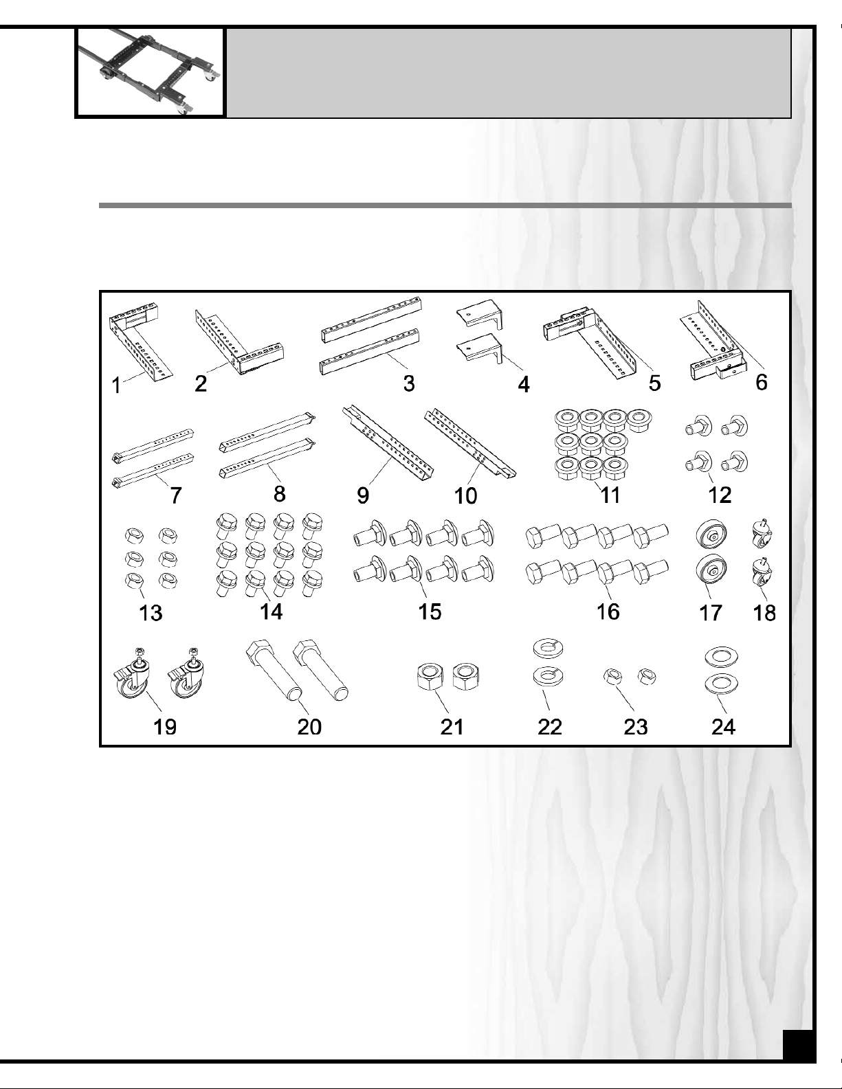
UNPACKING & CHECKING CONTENTS
Remove all parts and components from the box and check f or missing or damaged items as per the list of contents
below.
Note: please report any damaged or missing items to your General® International distributor immediately.
1. FRONT BRACKET (UPPER)
2. FRONT BRACKET (LOWER)
3. ADJUSTMENT SLEEVE (2)
4. FRONT WHEEL BRACKET (2)
5. REAR BRACKET (UPPER)
6. REAR BRACKET (LOWER)
7. FRONT EXTENSION BAR (2)
8. REAR EXTENSION BAR (2)
9. ADJUSTABLE BRACKET (BIG)
10.ADJUSTABLE BRACKET (SMALL)
11.3/8” FLANGE NUT (10)
12.5/16” X 1/2” CARRIAGE BOLT (4)
13.5/16” FLANGE NUT (6)
14.5/16” FLANGE BOLT (12)
15.3/8” X 3/4” CARRIAGE BOLT (8)
16.HEX. HEAD BOLT (8)
17.FIXED WHEEL (2)
18.CASTER (2)
19.LOCKABLE CASTER WITH NUT (2)
20.FIXED WHEEL SHAFT (2)
21.1/2” HEX. NUT (2)
22.1/2” LOCK WASHER (2)
23.5/16” HEX. NUT (2)
24.FLAT WASHER (2)
4
Page 6

ASSEMBLY INSTRUCTIONS
STEP 2
Assemble the upper and lower front brackets (#1 & 2)
as shown using four 3/8”x 3/4” carriage bolts (#15) and
four 3/8” flange nuts (#11) with the heads of the bolts
facing in towards the machine and the nuts on the
outside face of the base (See inset). Set the inside
dimensions of the bracket sides as close as possible to
the length (measurement B from step 1 above) of your
machine.
STEP 3
Using four flange bolts (#14) per wheel bracket, install
the two front wheel brackets (# 4) to each end of the
front bracket assembly as shown.
REQUIREMENTS FOR ASSEMBL
Y AND SET UP
• Socket wrench kit
•Adjustable wrench
• Tape measure
• An extra person for help with lifting
5
STEP 1
Before starting to assemble the mobile base, take note of the outside measurements of your machine and the
extension table support legs as shown.
?
B
?
A
?
D
?
C
Page 7

STEP 4
Assemble the upper and lower rear brackets (# 5 & 6)
as shown using four 3/8”x 3/4” carriage bolts (#15) and
four 3/8” flange nuts (#11) with the heads of the bolts
facing in towards the machine and the nuts on the
outside edge of the base. Set the inside dimensions of
the bracket sides as close as possible to the width
(measurement B from step 1 above) of your machine.
STEP 5
Using your machine width (measurement A from step
1) as your reference attach the two adjustment sleeves
(#3) at each end to join the front bracket assembly
to the rear bracket assembly. Use 2 hex bolts (#16) at
each end of each adjustment sleeve - 2 sleeves x 2
ends x 2 bolts = total 8 bolts.
STEP 6
Using the two 1/2”x 3”fixed wheel shafts (#20) and two
flat washers (#24) assemble the two fixed wheels (#17)
onto the rear bracket as shown.
STEP 7
Secure the lockable casters (#19) under the front wheel
brackets (#4) with a 1/2”lock washer (#22) and a 1/2”
flange nut (#21) on each caster as shown.
STEP 8
Using your support legs width (measurement D from
step 1) as a reference, assemble the small and large
adjustable brackets (#9 & 10) with four 5/16”x 1/2” carriage bolts (#12) and flange nuts (#13).
Note: regardless of the exact support legs width (measurement D from step one) when assembling the brackets at
least one of the round holes at each end of the adjustable
brackets should remain exposed to allow the extension
bars to be fastened to the brackets.
6
Page 8

STEP 9
Attach the casters (#18) to the underside of the
adjustable bracket assembly (#9 & 10) with the 5/16”
nuts (#23).
STEP 10
Using two 5/16” flange nuts (#13) secure the two rear
extension bars (#8) to the adjustable bracket assembly
(#9 & 10).
STEP 11
Using two 3/8” flange nuts (#11) secure the two front
extension bars (#7) to the rear brackets (#5 & 6) base
assembly – make sure to space the extensions bars to
the same width on the base as the rear extension bars
on the adjustable bracket.
STEP 12
Slide the rear extension bars (#8) onto the front extension bars adjusting the width of the entire assembly as
per the machine to support legs width (measurement
C from step one) and then secure the extension bar
assembly using two flange bolts (#14) per bar.
Your mobile base assembly should now be completed. Before attempting to install the machine on the base,
double check all measurements to ensure that the machine will fit onto the base without problems. Lengthen or
shorten-up any base dimensions as needed, then re-check your measurements.You are now ready to install your
machine onto your mobile base.
Note: If equipped with an extension table and support legs – remove and set these parts aside until the machine
has been installed onto the mobile base. Re-install the extension table and support legs on the machine once it is
fitted to the mobile base.
Note: Follow the manufacturers’ recommendations for handling or lifting the machine. Make sure to have adequate
help available for lifting – Do Not Over Exert!
7
Page 9

8
PARTS LIST
50-030
PART N0. REF. N0. DESCRIPTION SPECIFICATION QTY
50030-01 FRONT BRACKET (UPPER) 1
50030-02 FRONT BRACKET (LOWER) 1
50030-03 ADJUSTABLE SLEEVE 2
50030-04 FRONT WHEEL BRACKET 2
50030-05 REAR BRACKET (UPPER) 1
50030-06 REAR BRACKET (LOWER) 1
50030-07 FRONT EXTENSION BAR 2
50030-08 REAR EXTENSION BAR 2
50030-09 ADJUSTABLE BRACKET (SMALL) 1
50030-10 ADJUSTABLE BRACKET (LARGE) 1
50030-11 FLANGE NUT 3/8” 10
50030-12 CARRIAGE BOLT 5/16”X 1/2” 4
50030-13 FLANGE NUT 5/16” 6
50030-14 FLANGE BOLT 5/16”X 1/2” 12
50030-15 CARRIAGE BOLT 5/16”X 1/2” 8
50030-16 HEX. HEAD BOLT 3/8”X 3/4” 8
50030-17 FIXED WHEEL 2
50030-18 CASTER (SMALL) 2
50030-19 LOCKABLE CASTER WITH NUT 2
50030-20 FIXED WHEEL SHAFT 1/2”X 3” 2
50030-21 HEX. NUT 1/2” 2
50030-22 LOCK WASHER 1/2” 2
50030-23 HEX. NUT 5/16” 2
50030-24 FLAT WASHER 2
Page 10

IMPORTANT: When ordering replacement parts, always give the model number, serial number of
the machine and part number. Also a br ief description of each item and quantity
desired.
50-030
8360 Champ-d’Eau, Montreal (Quebec)
Canada H1P 1Y3
Tel.: (514) 326-1161
Fax : (514) 326-5565
Parts & Service
Fax : (514) 326-5555 Order Desk
orderdesk@general.ca
www.general.ca
 Loading...