


TROUBLESHOOTING
• Under normal operation the LED should light when the furnace blower is running.
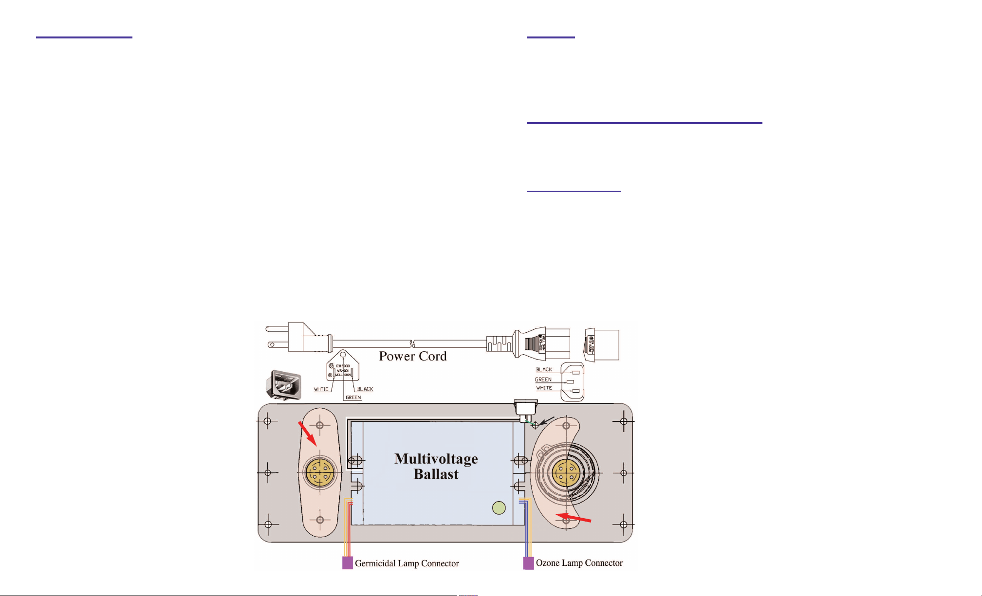
• Both lamps operate from the same multivoltage ballast.
If the LED does not light:
1. Check to be sure there is power to the unit.
2. Be sure lamp connectors are fastened securely.
3. If the LED still does not light, replace lamp(s).
4. If still not operating, replace ballast.
(Please note standard off-the-shelf lamps are not compatible with this unit.
Use of improper lamps will void warranty.)
WARRANTY
The manufacturer warrants the GUV25403A air purification unit against defects in materials and
workmanship for a period of four (4) years from the date of installation. Lamps carry a warranty for
the useful life of the lamp, two (2) years. This warranty does not cover broken lamps due to shipping,
installation or handling. This warranty gives you specific legal rights and you may also have other
rights which vary from state to state.
Airstream
18 3/4”
16” Germicidal UV-C Lamp
Air flow
GeneralAire GUV25403A Multivoltage Air Purifier
Installation & Maintenance Instructions
UNPACKING THE UNIT
Each GeneralAire GUV25403A AirPurifier unit is shipped with the ozone
lamp installed and the germicidal lamp placed in a tube with protective
packaging. Carefully remove lamp from the box taking care to not touch
the glass portion of the lamp with bare hands. Oils from the hands can
cause “hot spots” which reduce lamp life. Handle by the porcelain caps or
use a soft cloth. If you accidentally touch a lamp, wipe it off using a soft
cloth dampened with rubbing alcohol. The lamp is fragile and proper care
must be taken when removing from packaging.
Be sure all parts are included in the following list:
• Generalaire GUV25403A Air Purifier
• 16” Germicidal Twin H Lamp
• Four Sheet Metal Screws
• Installation & maintenance instructions
(packed in lamp box)
Pat. Pending
Ozone
Output
Control
3 1/2”
Box size is
11.75 high
x 4.25 wide.
Protective Shield
5” Ozone UV-V Lamp
© 2006 For service please call 248-476-5100
GUV
25403A
Air Purifier
Return
Air Duct
Furnace
IMPORTANT: SAFETY INSTRUCTIONS
IMPORTANT: Instructions de securité
When installing and using this electrical equipment, basic safety precautions should always be followed including the following:
1. READ AND FOLLOW ALL INSTRUCTIONS.
2. Minimum living space for this product is 1,200 square feet.
3.
Always be sure the unit is unplugged during installation or service procedures.
4.
The ultraviolet light produced by the UV lamp is harmful to your eyes. Do not look directly at
the lamp. Should it become necessary to view the lamp, use UV-protected sunglasses.
Lors de l’installation et de l’utilisation de cet équipement, des précautions devront être suivies.
1- Lire et suivre les étapes attentivement.
2- Espace minimum d’une habitation pour ce produit est de 1,200 pi. carrés
3- Assurez vous de toujours débrancher avant l installation ou le service.
4- Ne pas regarder la lampe directement avec les yeux. Si nécessaire de le faire,
veuillez porter les lunettes de soleil contre les rayons U.V.
INSTALLATION: Living space, 1,200 square feet minimum.
• Best results are achieved when the unit is installed where the HVAC system air temperature is most constant.
Therefore, the preferred installation is on the return side of the furnace. If return side installation is not possible,
install the unit on the supply side, keeping it as far from the heat/cooling source as possible, and in the main airstream.
Mount the GUV25403A upstream when installing in combination with a GeneralAire H.E.P.A. unit.
If there is an existing ozone producing device on the furnace, install one of our non-ozone producing models.
WIRING
The multivoltage ballast is self-adjusting and operates with voltages from 120 - 240 VAC. This unit must
cycle with the furnace blower. Install provided 120 VAC power cord and plug the unit into a 120 VAC outlet which is
interlocked with the furnace blower. If an EAC terminal is available, supply power to the outlet from the EAC terminal.
Connect in accordance with local wiring codes. If there is no EAC terminal, interlock the UV unit with the furnace blower using an appropriate alternate. After installing verify voltage is operating between 120 - 240 VAC with air handler
operating. An optional 240 VAC power cord is available, Part #PC-240, for 240 VAC installations.
• Do not locate the unit within 20” of any plastic material that will be directly exposed to the UV light, such as
a return side humidifier or certain types of air filters. Check with the filter manufacturer to see if their material is
UV resistant. Over time, UV light will degrade many plastic materials.
• Do not touch the glass portion of the lamps with bare hands because oils from the hands can cause “hot spots”
which reduce lamp life. Handle either by the porcelain caps or use a soft cloth. If you accidentally touch a
lamp, wipe it off, using a soft cloth dampened with rubbing alcohol.
1. Cut out the shaded area of the installation template. (See insert)
2. Center template on the longitudinal axis of the plenum using tape to hold it in place.
Trace the hole pattern for the unit and mark centers for mounting screws.
(Airflow direction is marked on the air purifier unit.)
3. Cut opening for the unit and drill 9/64” holes for sheet metal screws.
4. Remove the cover from the unit by removing the top and bottom retaining nuts using an 11/32 size
nut driver and set aside. Do not remove the ozone control knob.
(For easier installation rotate ozone control knob
to the center position before removing cover.)
5. Attach unit to air duct using the four
sheet metal screws provided.
6. Remove germicidal lamp holder (Figure A)
using a 11/32 size nut driver.
7. Slide germicidal lamp into lamp opening.
Germicidal
Lamp
Holder
8. Reinstall lamp holder.
SETTING THE OZONE OUTPUT LEVEL
• The air purification process occurs only while air is circulating through the HVAC system.
• The ozone level can be easily adjusted as needed using the “Ozone Output” knob on the front cover of unit.
Start with the ozone setting in the normal range. Decrease the setting if ozone odor is detectible.
If household odors are noticeable after 24 hours, increase the setting.
MAINTENANCE
This maintenance schedule is only a guideline, determined by average conditions. Actual conditions will dictate
the frequency of cleaning and/or replacement of lamps. Do not touch the glass portion of the lamps with bare hands
because oils from the hands can cause “hot spots” which reduce lamp life. Handle either by the porcelain caps
or use a soft cloth. If you accidentally touch a lamp, wipe it off, using a soft cloth dampened with rubbing alcohol.
CLEANING THE LAMPS -
Recommended interval: 12 months
Replacement lamps are available through your HVAC contractor.
(Follow procedure below)
REPLACING THE LAMPS - Recommended interval: 24 months. (Follow procedure below excluding #6.)
1.
Unplug the power cord from the outlet, or disconnect power to the unit.
2. Remove the cover from the unit by removing the top and bottom
retaining nuts using a 11/32 size nut driver. Do not remove the Ozone
Control knob. (For easier installation rotate the ozone control knob to
the center position before removing cover.)
3. Unplug the lamp connector from the end of each lamp.
4. Remove lamp holders using a 11/32 size nut driver. (Figure A)
5. Remove each lamp by grasping the porcelain cap and
Ground
extract carefully.
6. Using a soft cloth moistened with rubbing alcohol, wipe down
each lamp. If there is a large build-up of dust particles, you may
wish to use a can of air first. Always handle lamps by end caps.
9. Plug in lamp connector to the end of lamp.
10. Replace cover and align the ozone control
knob with ozone adjustment linkage by
gently turning the knob until linkage
clicks into place. Secure cover using
the two retaining nuts.
(Figure A)
Ozone
Lamp
Holder
7. Slide one lamp back into lamp opening. Reinstall lamp holder.
8. Repeat step 7 for second lamp.
9. Plug the lamp connector to the end of each lamp.
10. Replace cover and align the ozone control knob with ozone
adjustment linkage by gently turning the knob until linkage
clicks into place. Secure cover using the two retaining nuts.
11. Plug power cord back into outlet, or restore power to unit.

11 3/4”
10 1/4”
2 1/2”
INSTALLATION TEMPLATE GUV25403A
4”
CUT ON DOTTED LINE
1. Cut out shaded area of template
2. Place template on the return path of the HVAC system and trace the hole pattern for the unit and mark centers for mounting screws. Unit must be oriented so long
dimension is parallel to the direction of the air flow.
3. Drill one 9/64” hole at each of these locations for sheet metal screws.
4. Cut opening for the unit.
5. Install unit into air duct so that airflow matches direction indicated on side of unit using the four sheet metal screws provided.
 Loading...