


PFSS5PJZCSS
GE PFSS5PJZCSS, PFSS5PJZASS, PFSS5NFZCSS, PFSS5NFZBSS, PFSF5PJZAWW Owner’s Manual
...
N
GEAppliances.com
Safety Instructions ........... 2,3
Operating Instructions
Additional Features ................. 8
Automatic Icemaker ............... 11
Care and Cleaning ............. 12, 13
Controls .......................... 4, 5
Crispers and Pans ................... 9
Freezer ............................ 10
Replacing the Light Bulbs .......... 14
Shelves and Bins .................. 7, 8
Water Dispenser ................... 11
Water Filter ......................... 6
Installation Instructions
Installing the Anti-Tip
Floor Bracket ................... 18, 19
Installing the Refrigerator ...... 20-24
Installing the Water Line ........ 33-35
Preparing to Install
the Refrigerator .................... 17
Removing and Replacing the
Freezer Drawer ................ 25, 26
Reversing the Door Swing
(Single Door Refrigerator
Models onlg) ................... 27-29
Removing and Replacing
the Doors (Double Door
Refrigerator Models onlg) ....... 30-32
Trim Kits and Decorator Panels .... 15, 16
Models 2_land 25
Cong61oteur inf@ieur
R frig rateurs
La section ffangaise commence 6 lapage 45
Congelador inferior
Refrigeradores
La secci6n en espa_ol empieza en la p6gina89
0
Troubleshooting Tips ...... 36-4o
Normal Operating Sounds .......... 36
Consumer Support
Consumer Support ........ Back Cover
Performance Data Sheet ........... 43
State of California Water
Treatment Device Certificate ....... 44
Warrantg for Canadian
Customers ......................... 42
Warrantg for U.S. Customers ....... 44
Write the model and serial
numbers here:
Model #
Serial #
Find these numbers on a label
on the right side, near the top of the
refrigerator compartment.
200D9366P019 49-60609-2 04-10 GE
IMPORTANTSAFETYINFORMATION.
READALL INSTRUCTIONSBEFOREUSING.
A WARNING!
Use this appliance only for its intended purpose as described in this Owner's Manual.
SAFETY PRECAUTIONS
When using electrical appliances, basic safety precautions should be followed, including the following:
This refrigerator must be properlg installed
and located in accordance with the Installation
Instructions before it is used.
Donot allow children to climb, stand or hang
on the shelvesinthe refrigerator.Theg could
damage the refrigerator and seriouslg injure
themselves.
Donot touch the cold surfaces in the freezer
compartment when hands are damp or wet.
Skinmag stick to these extremelg cold surfaces.
Donot store or use gasoline or other flammable
vapors and liquidsin the vicinitg of this or ang other
appliance.
iiii!i!i!_ii}
Keepfingers out of the "pinch point" areas;
clearancesbetween the doors and between the
doorsand cabinet are necessarilgsmall. Becareful
closing doorswhen children are in the area.
Inrefrigerators with automatic icemakers, avoid
contact with the moving parts ofthe ejector
mechanism,or with the heating element that
releasesthe cubes.Do not placefingers or hands
on the automatic icemaking mechanism while the
refrigerator is plugged in.
Unplugthe refrigerator before cleaning and making
repairs.
NOTE:Westrongly recommend that any servicing
beperformed by a qualified individual.
Settingeither or both controls to 0 (offJdoes not
remove power to the light circuit.
Donot refreezefrozenfoods which have thawed
completelg.
A DANGER! RISK OF CHILD ENTRAPMENT
PROPERDISPOSAL OF THE REFRIGERATOR
Childentrapment and suffocation are not problems of
the past. Junked or abandoned refrigerators are still
dungerous...evenif theg will sit for "just u few dags."If
gou are getting rid of gour oldrefrigerator, please
follow the instructions below to help prevent
accidents.
Before You ThrowAway Your Old
Refrigerator or Freezer:
Takeoff the doors.
Leavethe shelves in place sothat children mag not
easilgclimb inside.
Refrigerants
All refrigeration products contain refrigerants,
which under federal low must be removed prior to
product disposal. If gou ore getting rid of on old
refrigeration product, check with the compong
handling the disposal about what to do.
USEOF EXTENSION CORDS
Because of potential safety hazards under certain conditions, we strongly recommend against
the use of an extension cord.
However,if gou must use an extension cord, it is ubsolutelg necessargthat it be a UL-listed(inthe United
States)or a CSAcertified (inCanada),3-wire grounding tgpe appliance extension cord having a grounding tgpe
2
plug and outlet and that the electrical rating of the cord be 15amperes (minimum) and 120volts.

GEAppliunces.com
A WARNING!
HOW TOCONNECTELECTRICITY
Do not, under any circumstances, cut or remove the third (ground) prong from the power cord.
For personal safety, this appliance must be properly grounded.
Thepower cord of this appliance isequipped with a 3-
prong (grounding) plug which mates with a standard
:S-prong(grounding)wall outlet to minimizethe
possibility of electric shock hazard from this
appliance.
Have the wall outlet and circuit checkedby a
qualified electricianto make surethe outlet is
properly grounded.
Where a standard 2-prong wall outlet is encountered,
it is your personal responsibility and obligation to
have it replaced with a properly grounded 3-prong
wall outlet.
Therefrigerator should always be plugged into its
own individual electrical outlet which hasa voltage
rating that matches the rating plate.
Thisprovides the best performance and alsoprevents
overloading housewiring circuits which could cause a
fire hazardfrom overheated wires.
Never unplug your refrigerator by pulling on the
power cord.Always grip plug firmly and pull straight
out from the outlet.
Repairor replaceimmediately all power cords that
have become frayed or otherwise damaged. Do not
usea cord that shows cracks orabrasion damage
along its length or at either end.
When moving the refrigerator away from the wall, be
careful not to roll over or damage the power cord.
READAND FOLLOWTHISSAFETYINFORMATIONCAREFULLY.
SAVETHESEINSTRUCTIONS
About the controlswith temperature settings.
(onsome models)
[] TEMPERATURE SET
WARMER _ WARNER
Ico'° R
rE O_ F R_°mmended 37_ F Rec°mmended
[] []
[]
EZ]
Hold 3 seconds to reset Hold 3 seconds
(onsome models)
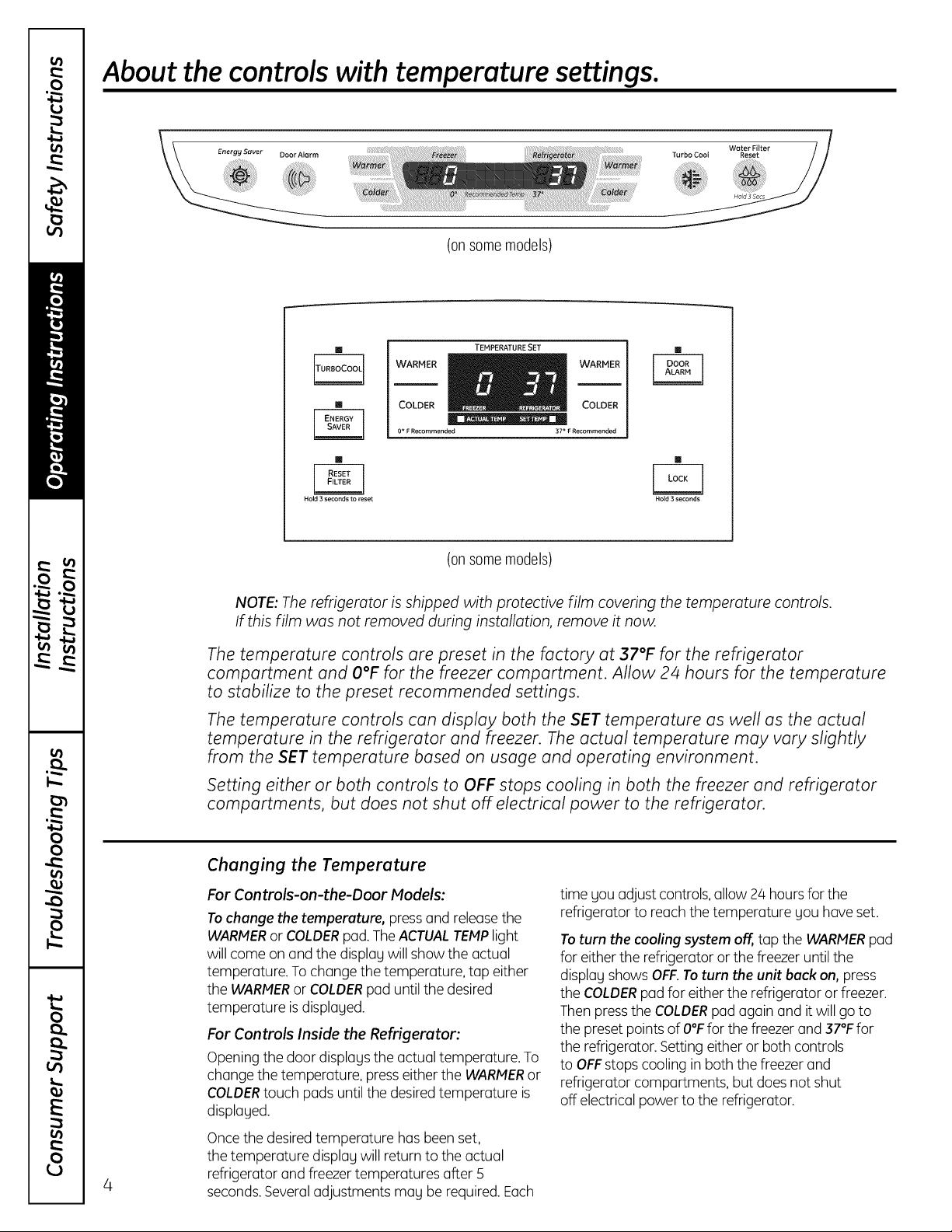
NOTE: The refrigerator is shipped with protective film covering the temperature controls.
If this film was not removed during installation, remove it now.
The temperature controls ore preset in the factory at 37°F for the refrigerator
comportment and O°F for the freezer comportment. Allow 2/4hours for the temperature
to stabilize to the preset recommended settings.
The temperature controls con disptoy both the SET temperature as well as the actual
temperature in the refrigerator and freezer. The actual temperature may vary slightly
from the SET temperature based on usage and operating environment.
Setting either or both controls to OFF stops cooling in both the freezer and refrigerator
comportments, but does not shut off electrical power to the refrigerator.
Changing the Temperature
For Controls-on-the-Door Models:
Tochange the temperature, pressand releasethe
WARNERor COLDERpod.The ACTUALTENPlight
will come on and the displuUwill show the actual
temperature. To change the temperature, tap either
the WARNERor COLDERpad until the desired
temperature isdisplayed.
For Controls Inside the Refrigerator:
Opening the door displogs the actual temperature. To
change the temperature, presseither the WARNERor
COLDERtouch pads until the desiredtemperature is
displayed.
Oncethe desired temperature has been set,
the temperature displag will return to the actual
4
refrigerator and freezer temperatures after 5
seconds.Severaladjustments mog be required.Each
time gou adjust controls,allow 24 hours for the
refrigerator to reach the temperature gou haveset.
Toturn the cooling system off,,top the WARNERpad
for either the refrigerator or the freezer until the
displug shows OFF.Toturn the unit back on, press
the COLDERpod for either the refrigerator orfreezer.
Thenpressthe COLDERpad again and itwill go to
the preset points of O°Ffor the freezer and 37°Ffor
the refrigerator. Setting either or both controls
to OFFstopscooling inboth the freezer and
refrigerator compartments, but does not shut
off electrical power to the refrigerator.
About TurboCook TM (on some models) GEAppliances.com
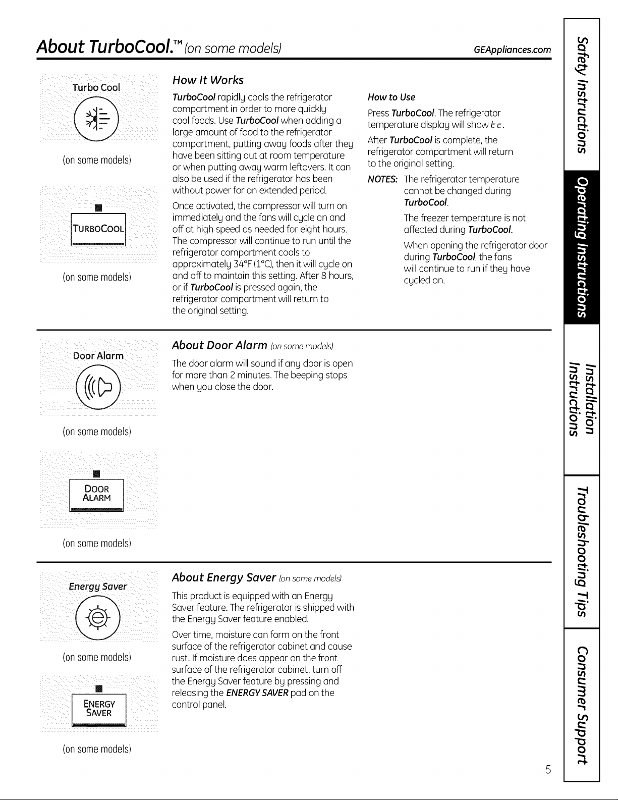
Turbo CoOl How It Works
How to Use
PressTurboCool.The refrigerator
temperature display will show be.
After TurboCool is complete, the
refrigerator compartment will return
to the original setting.
NOTES: Therefrigerator temperature
cannot be changed during
TurboCool.
Thefreezer temperature is not
affected during TurboCool.
When opening the refrigerator door
during TurboCool, the fans
will continue to run if they have
cycled on.
(on somemodels)
TURBOCOOL
(on somemodels)
TurboCool rapidly cools the refrigerator
compartment in order to more quickly
coolfoods. Use TurboCool when adding a
large amount of food to the refrigerator
compartment, putting away foods after they
have been sitting out at room temperature
or when putting away warm leftovers. It can
alsobe usedif the refrigerator has been
without power for an extended period.
Onceactivated, the compressor willturn on
immediately and the fans will cycle on and
off at high speedas neededfor eight hours.
Thecompressor will continue to run until the
refrigerator compartment coolsto
approximately 34°F(I°C),then it will cycle on
and off to maintain this setting.After 8 hours,
or if TurboCool is pressed again, the
refrigerator compartment will return to
the original setting.
(on somemodels)
/ i i ii _ _ i_TMiii ii_ _iii
DOOR
ALARM
(on somemodels)
Energysaver
@
(on somemodels)
, ENERGYsAVER,
About Door Alarm (onsomemodels)
Thedoor alarm will sound ifany door isopen
for morethan 2 minutes.The beeping stops
when you close the door.
About Energy Saver (onsomemodels)
Thisproduct is equipped with an Energy
Saverfeature. The refrigerator isshipped with
the EnergySaverfeature enabled.
Overtime, moisture can form on the front
surface of the refrigerator cabinet and cause
rust. If moisture doesappear on the front
surface of the refrigerator cabinet, turn off
the EnergySaverfeature by pressing and
releasingthe ENERGYSAVERpad onthe
control panel.
(on somemodels)
About the water filter. (onsome models)
¸¸¸7¸¸
J
Holder
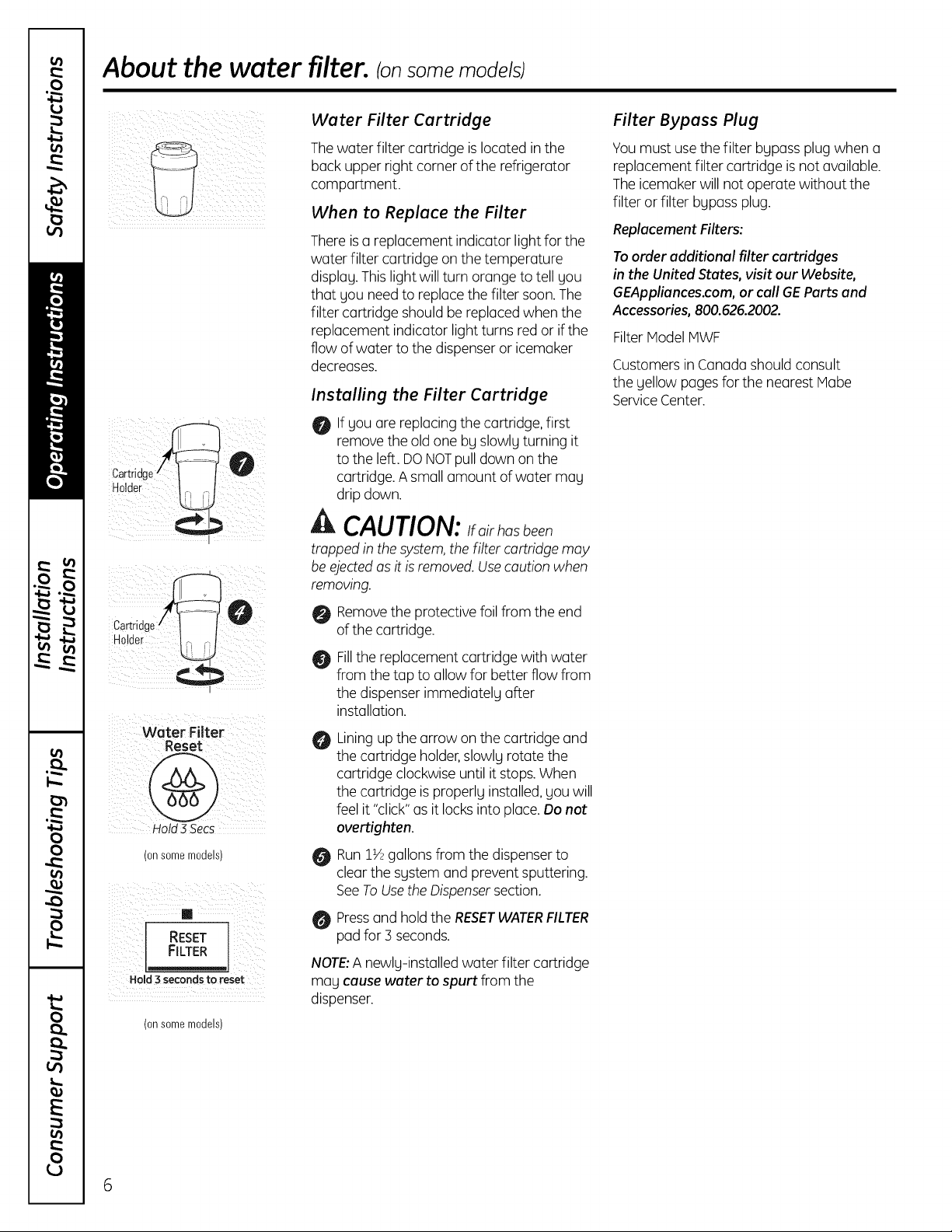
Water Filter Cartridge
Thewater filter cartridge islocated in the
back upper right corner of the refrigerator
compartment.
When to Replace the Filter
There is a replacement indicator light for the
water filter cartridge on the temperature
displag.This lightwill turn orange to tell gou
that gou need to replacethe filter soon.The
filter cartridge should be replacedwhen the
replacement indicator light turns red or if the
flow of water to the dispenser or icemaker
decreases.
Installing the Filter Cartridge
0 If gou are replacing the cartridge, first
remove the old one bg slowlg turning it
to the left. DO NOTpull down on the
cartridge. A small amount of water mag
drip down.
A CAUTION:Ifairhasbeen
trapped in the system,the Filtercartridge may
be ejectedasit is removed.Usecaution when
removing.
Filter Bypass Plug
Youmust usethe filter bgpass plug when a
replacement filter cartridge is not available.
Theicemaker will not operate without the
filter or filter bgpass plug.
Replacement Filters:
Toorder additional filter cartridges
in the United States, visit our Website,
GEAppliances.com, or call GEParts and
Accessories, 800.626.2002.
Filter IVlodelIVlWF
Customersin Canadashould consult
the gellow pages for the nearest Mabe
ServiceCenter.
Cartridge
Holder
Water Filter
" V
Hold 3 Secs
(onsomemodels) O
RESET
FILTER
HeM 3 seconds to reset
(onsomemodels)
Removethe protective foil from the end
0
of the cartridge.
Fillthe replacement cartridge with water
O
from the tap to allow for better flow from
the dispenser immediatelg after
installation.
A
Liningup the arrow on the cartridge and
the cartridge holder,slowlg rotate the
cartridge clockwise until it stops.When
the cartridge isproperlg installed,gou will
feel it "click"as it locks into place.Do not
overtighten.
RunIY_gallons from the dispenser to
clear the sgstem and prevent sputtering.
SeeToUsetheDispensersection.
Pressand holdthe RESETWATERFILTER
pad for 3 seconds.
NOTE:A newlg-installed water filter cartridge
mag cause water to spurt from the
dispenser.
6
About the shelves and bins. GEAppliancescom
Not all features are on all models.
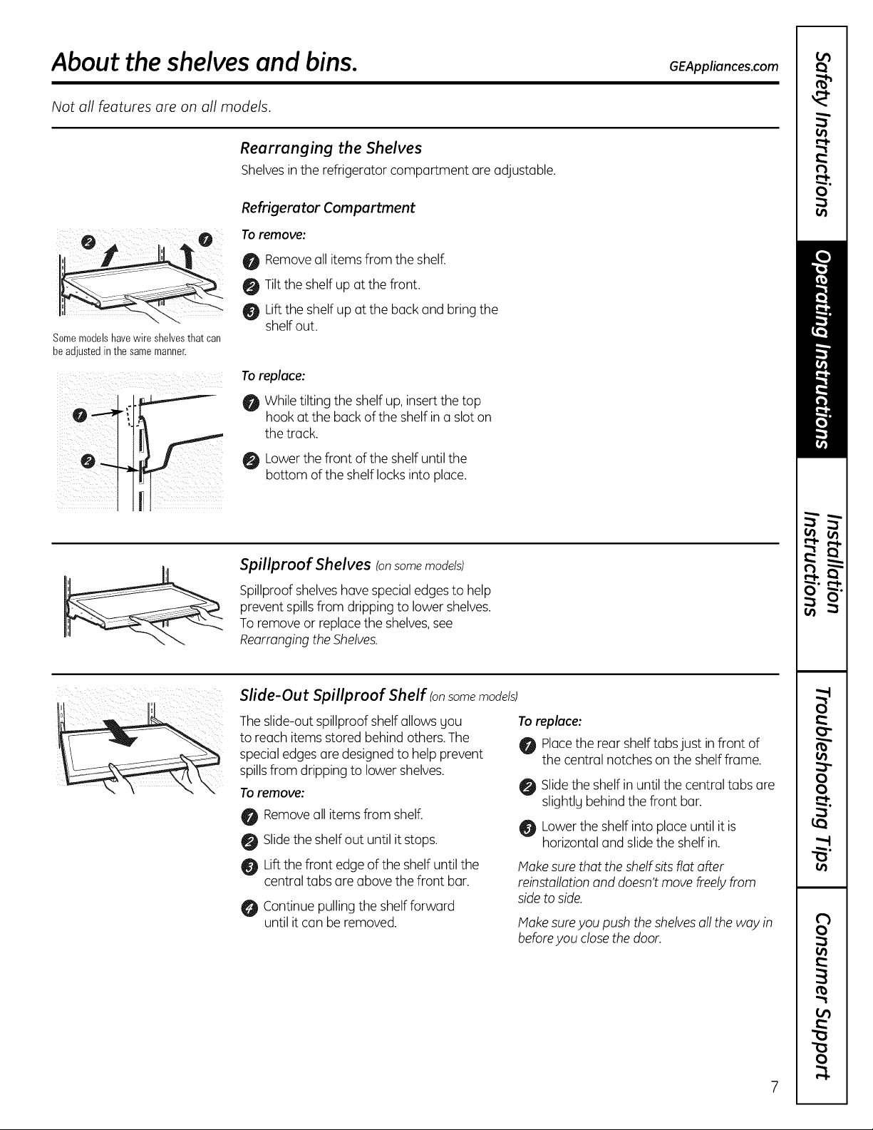
Rearranging the Shelves
Shelvesinthe refrigerator compartment are adjustable.
Refrigerator Compartment
Toremove:
O Removeall items from the shelf.
0 Tilt the shelf up at the front.
Liftthe shelf up at the back and bring the
Somemodelshavewire shelvesthatcan
beadjustedinthe samemanner.
shelf out.
Toreplace:
While tilting the shelf up, insertthe top
hook at the back of the shelf in a slot on
the track.
Lowerthe front of the shelf until the
bottom of the shelf locksinto place.
ir
Spillproof Shelves Ionsomemodels)
Spillproofshelves hovespecialedgesto help
prevent spillsfrom dripping to lower shelves.
Toremove or replace the shelves,see
Rearrangingthe Shelves.
Slide-Out Spillproof Shelf Ionsome models)
Theslide-out spillproof shelf allows gou
to reach items stored behind others.The
special edgesare designedto help prevent
spillsfrom dripping to lower shelves.
\
Toremove:
Removeall itemsfrom shelf.
Slidethe shelfout until it stops.
Liftthe front edge of the shelf until the
central tabs are above the front bar.
Continue pulling the shelf forward
until it can be removed.
Toreplace:
Placethe rearshelf tabsjust infront of
the central notches on the shelf frame.
Slidethe shelf in until the central tabs are
slightlg behind the front bar.
0 Lower the shelf into place until it is
horizontal and slide the shelf in.
Makesure that the shelf sitsfiat offer
reinstallationand doesn'tmove freelyfrom
sideto side.
Makesureyou push the shelvesall the way in
beforeyou closethe door.
7
About the shelvesand bins.
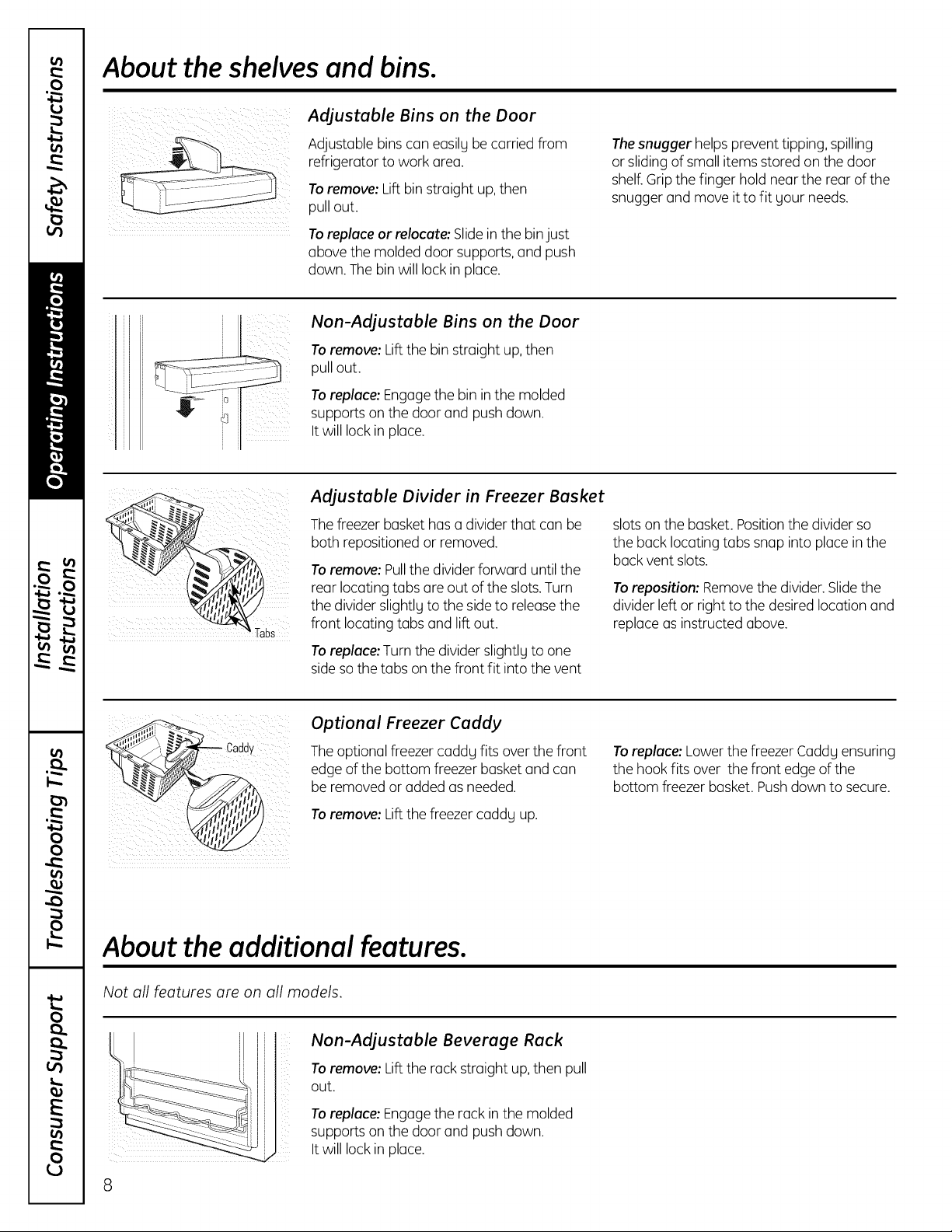
AdJustable Bins on the Door
Tabs
Adjustable bins can easilgbecarried from
refrigerator to work area.
Toremove: Lift bin straight up,then
pull out.
Toreplace or relocate: Slidein the binjust
above the molded door supports,and push
down. The bin will lock in place.
Non-AdJustable Bins on the Door
Toremove: Lift the bin straight up,then
pull out.
Toreplace: Engagethe bin in the molded
supports on the door and pushdown.
It will lock in place.
AdJustable Divider in Freezer Basket
Thefreezer basket has a divider that can be
both repositioned or removed.
Toremove: Pullthe divider forward until the
rear locating tabs are out of the slots.Turn
the divider slightly to the side to releasethe
front locating tabs and lift out.
Toreplace: Turnthe divider slightlg to one
sideso the tabs onthe front fit into the vent
Thesnugger helps prevent tipping, spilling
or sliding of small items stored on the door
shelf.Grip the finger hold near the rear of the
snugger and move it to fit gour needs.
slotson the basket. Positionthe divider so
the back locating tabs snap into place in the
back vent slots.
Toreposition: Removethe divider.Slidethe
divider left or right to the desired location and
replace as instructed above.
Optional Freezer Caddy
The optional freezer caddg fits over the front
ii ¸
edge of the bottom freezer basket and can
be removed or added as needed.
i
To remove: Liftthe freezer caddg up.
About the additional features.
Not all features are on all models.
Non-AdJustable Beverage Rack
Toremove: Lift the rack straight up,then pull
out.
To replace: Engage the rack in the molded
supports on the door and push down.
It will lock in place.
Toreplace: Lowerthe freezer Caddg ensuring
the hook fits over the front edge of the
bottom freezer basket. Pushdown to secure.
8
About the crispers and pans. GEAppliances.com
Not all features are on all models.
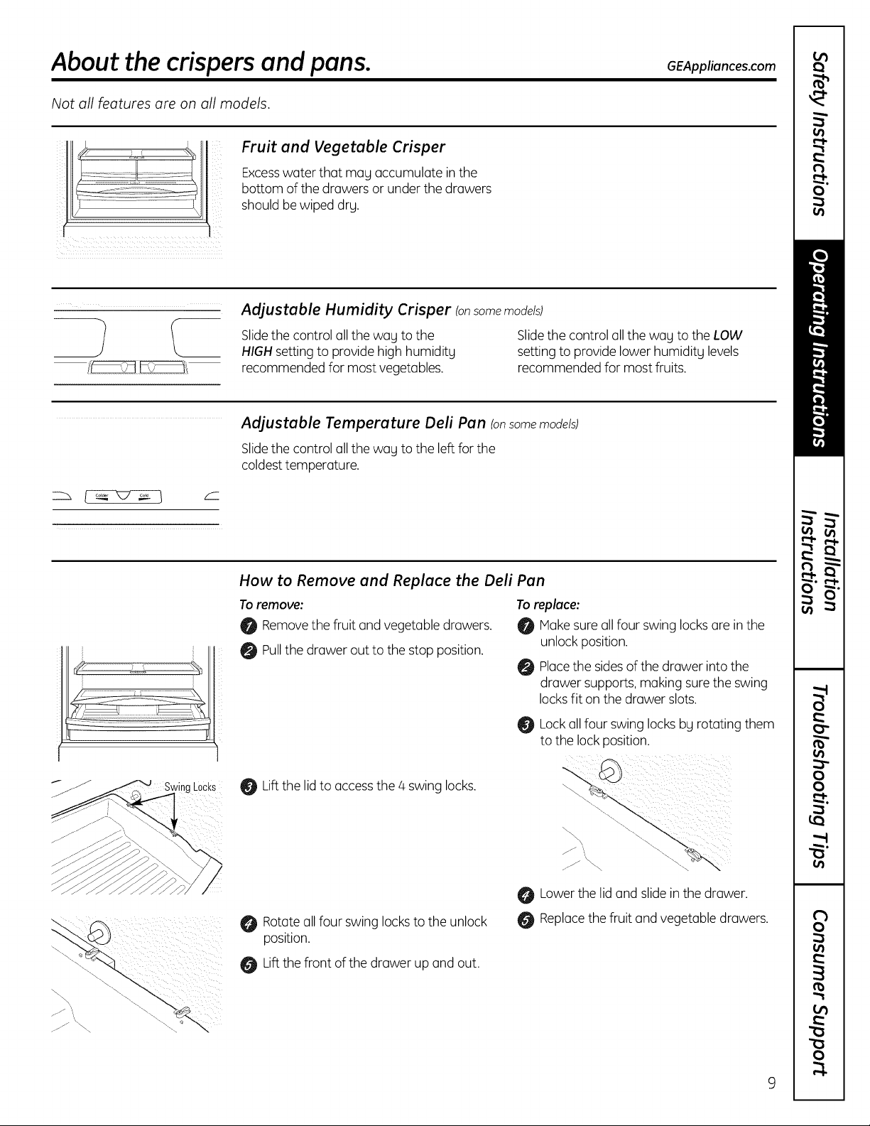
Fruit and Vegetable Crisper
Excesswater that mag accumulate inthe
bottom of the drawers or under the drawers
should bewiped dry.
Adjustable Humidity Crisper Ionsome models)
(_
Slidethe control all the way to the
HIGHsetting to providehigh humiditL
recommended for most vegetables.
Adjustable Temperature Deli Pan Ionsome models)
Slidethe control all the way to the left for the
coldesttemperature.
Slidethe control all the way to the LOW
setting to provide lower humidity levels
recommended for most fruits.
LOCKS
How to Remove and Replace the Deli Pan
Toremove: Toreplace:
0 Removethe fruit and vegetable drawers. 0 Makesure allfour swing locksare in the
0 Pullthe drawer out to the stop position.
Liftthe lidto accessthe/4 swing locks.
Rotateall four swing locksto the unlock
position.
Liftthe front of the drawer up and out.
unlock position.
Placethe sidesof the drawer into the
drawer supports, making sure the swing
locksfit on the drawer slots.
Lockall four swing locks bg rototing them
to the lock position.
Lowerthe lid and slide in the drawer.
Replacethe fruit and vegetable drawers.
About the freezer.
Not all features are on all models.
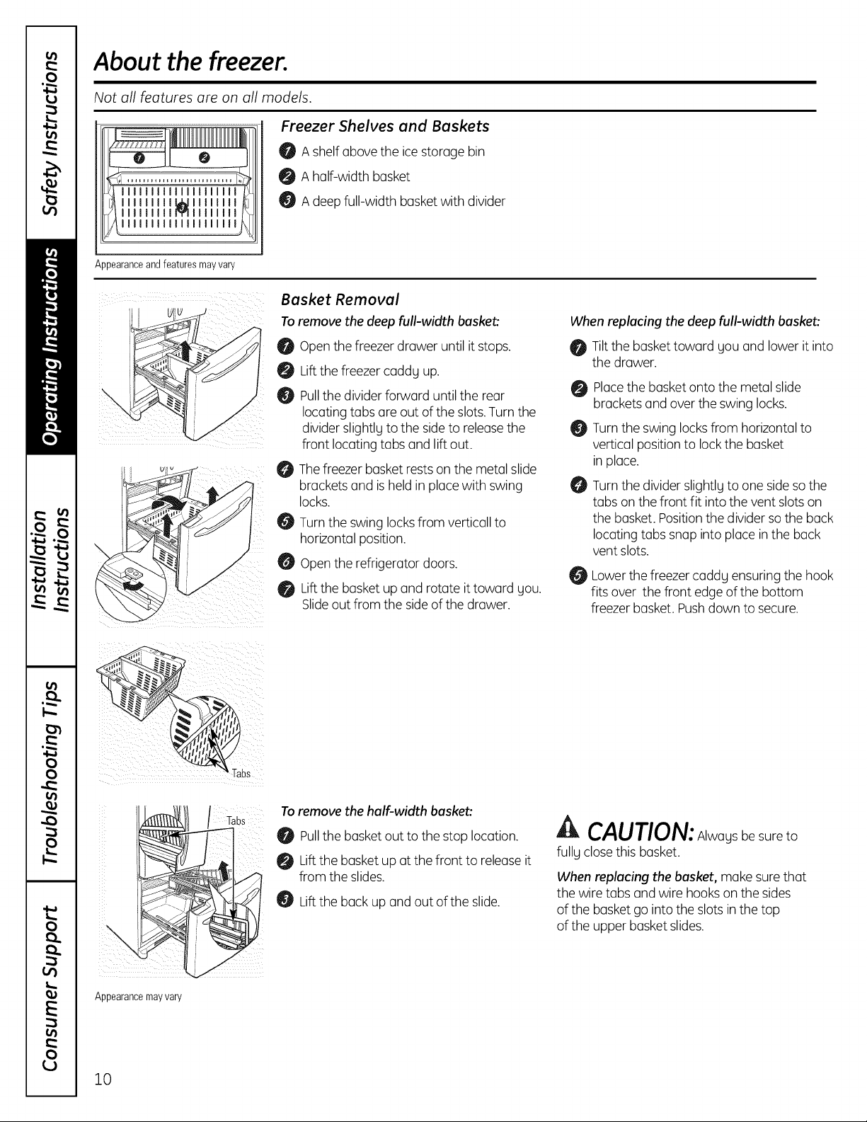
Freezer Shelves and Baskets
0 A shelfabove the icestorage bin
0 A half-width basket
II IMIll',llll
l
Appearanceand featuresmayvary
Basket Removal
Toremove the deep full-width basket:
A deepfull-width basket with divider
When replacing the deep full-width basket:
Open the freezer drawer until it stops.
Liftthe freezer caddy up.
Pullthe dividerforward untilthe rear
locating tabs are out ofthe slots.Turn the
divider slightly to the side to releasethe
front locating tabs and lift out.
Thefreezer basket restson the metal slide
O
brackets and is held in place with swing
locks.
0
Turnthe swing locksfrom verticall to
horizontal position.
0
Openthe refrigerator doors.
Lift the basket up and rotate it toward you.
@
Slideout from the side of the drawer.
Tiltthe baskettoward you and lower it into
the drawer.
Placethe basket onto the metal slide
brackets and over the swing locks.
Turnthe swing locksfrom horizontal to
vertical positionto lock the basket
in place.
O
Turnthe divider slightly to one sideso the
tabs on the front fit into the vent slots on
the basket. Positionthe divider sothe back
locating tabs snap into place in the back
vent slots.
0 Lower the freezer caddy ensuring the hook
fits over the front edge of the bottom
freezer basket. Pushdown to secure.
Appearance may vary
10
tabs
Toremove the half-width basket:
Pullthe basketout to the stop location.
Lift the basket up at the front to releaseit
from the slides.
Lift the back up and out of the slide.
A CAUTION:Alwaysbesureto
fully closethis basket.
When replacing the basket, make surethat
the wire tabs and wire hooks on the sides
of the basketgo into the slots in the top
of the upper basket slides.
About the automatic icemaker GEAppliances.com
A newly installed refrigerator may take 12 to 2/4 hours to begin making ice.
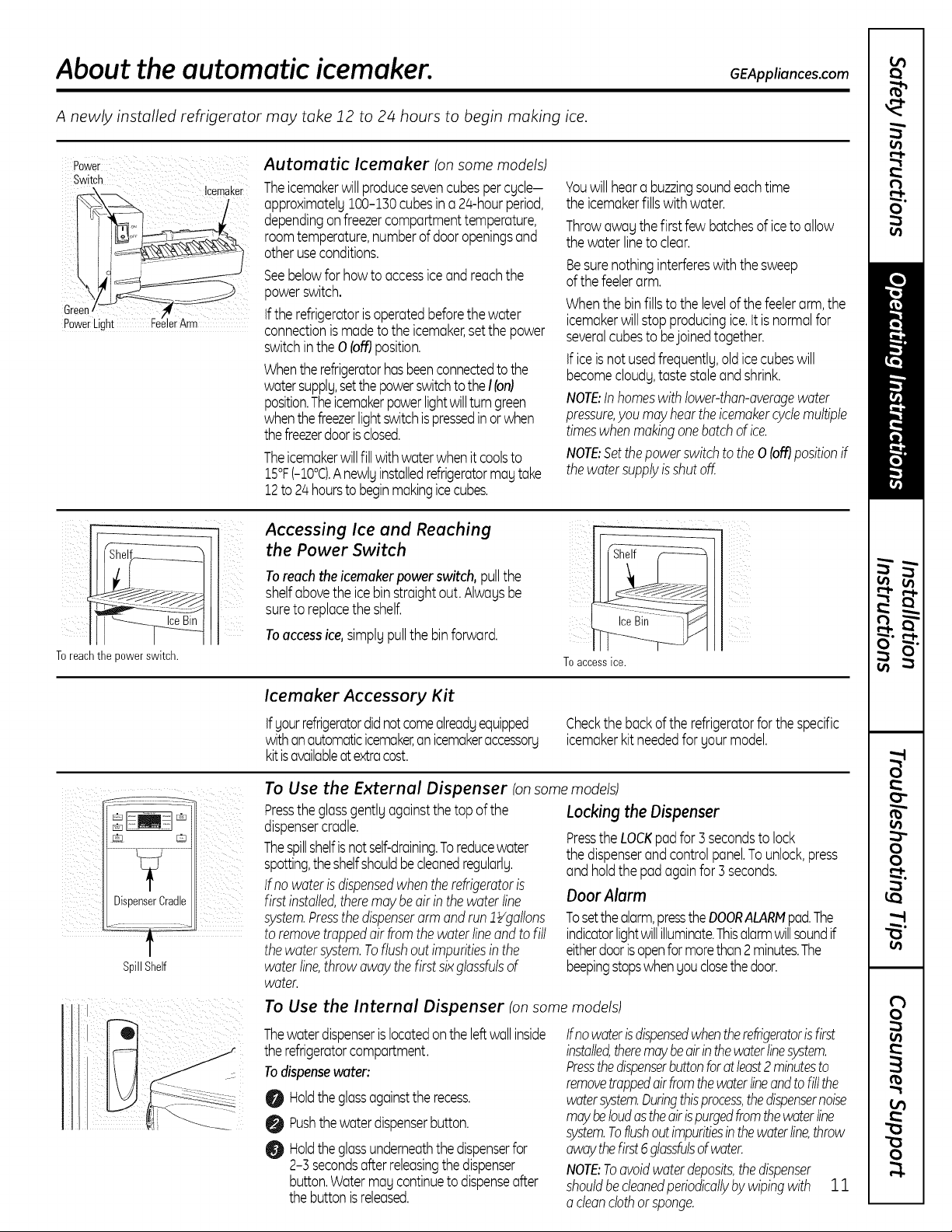
Power Automatic lcemaker lon some models)
Switch
Green
Power Light
Icemaker
Theicemakerwill producesevencubespercgcle-
approximatelg100-130cubesina 2/4-hourperiod,
dependingonfreezercompartmenttemperature,
roomtemperature,numberofdooropeningsand
otheruseconditions.
Seebelowfor howto accessiceandreachthe
powerswitch.
Iftherefrigeratorisoperatedbeforethewater
connectionismadetotheicemaker,setthe power
switchintheO(ofgposition.
Whentherefrigeratorhasbeenconnectedtothe
watersupplg,setthepowerswitchtotheI(on)
position.Theicemakerpowerlightwillturn green
whenthefreezerlightswitchispressedinorwhen
thefreezerdoorisclosed.
Theicemakerwillfill withwaterwhenitcoolsto
:].5°F(-:].0°C).Anewlyinstalledrefrigeratormagtake
12to 2/4hourstobeginmakingicecubes.
Youwillheara buzzingsoundeachtime
theicemakerfillswithwater.
Throwawagthefirstfewbatchesoficeto allow
thewater lineto clear.
Besurenothinginterfereswiththesweep
ofthefeelerarm.
Whenthebinfillsto thelevelofthefeelerarm,the
icemakerwillstopproducingice.itisnormalfor
severalcubesto bejoinedtogether.
Ificeisnotusedfrequentlg,oldicecubeswill
becomecloudg,tastestaleandshrink.
NOTE:Inhomeswithlower-than-overagewater
pressure,youmayheartheicemakercyclemultiple
timeswhenmakingonebotchofice.
NOTE:Setthepowerswitchtothe0 (ofgpositionif
thewatersupplyisshutoff.
Toreachthe sowerswitch.
O spenserCradle
SpillShelf
Accessing Ice and Reaching
the Power Switch
Toreachtheicemakerpowerswitch,pullthe
shelfabovetheicebinstraightout.Alwagsbe
sureto replacetheshelf.
ilJ
Toaccessice,simplgpullthebinforward.
Icemaker Accessory Kit
Ifgourrefrigeratordidnotcomealreadgequipped
withanautomaticicemaker,anicemakeraccessorg
kitisavailableat extracost.
To Use the External Dispenser Ionsomemodels)
Presstheglassgentlgagainstthetopof the
dispensercradle.
Thespillshelfisnotself-draining.Toreducewater
spotting,theshelfshouldbecleanedregularlg.
Ifnowaterisdispensedwhentherefrigeratoris
firstinstalled,theremaybeairin thewaterline
system.Pressthedispenserarmandrun!_/gallons
toremovetrappedair fromthewaterlineandtofill
thewatersystem.Toflushoutimpuritiesinthe
waterline,throwawaythefirstsixglassfulsof
water.
To Use the Internal Dispenser Ionsomemodels)
Thewaterdispenserislocatedontheleftwallinside
therefrigeratorcompartment.
Todispensewater:
O Holdtheglassagainsttherecess.
O Pushthewaterdispenserbutton.
Holdtheglassunderneaththe dispenserfor
2-3 secondsafterreleasingthedispenser
button.Watermagcontinuetodispenseafter
thebuttonis released.
x
x
}
To access ice.
Checkthebackofthe refrigeratorfor thespecific
icemakerkitneededforgourmodel.
Lockingthe Dispenser
PresstheLOCKpadfor3secondsto lock
thedispenserandcontrolpanel.Tounlock,press
andholdthepadagainfor 3seconds.
Door Alarm
Tosetthealarm,presstheDOORALARMpad.The
indicatorlightwillilluminate.Thisalarmwillsoundif
eitherdoorisopenformorethan2minutes.The
beepingstopswhengouclosethedoor.
Ifnowaterisdispensedwhentherefrigeratorisfirst
installed,theremaybeairinthewaterlinesystem.
Pressthedispenserbuttonforatleast2minutesto
removetrappedairfromthewaterlineandto fillthe
watersystem.Duringthisprocess,thedispensernoise
maybeloudastheairispurgedfromthewaterline
system.Toflushoutimpuritiesinthewaterline,throw
awaythefirst6glassfulsofwater.
NOTE:Toavoidwaterdeposits,thedispenser
shouldbecleanedperiodicallybywipingwith 3_3_
acleanclothorsponge.
Care and cleaning of the refrigerator.
Cleaning the Outside
Thedoor handles and trim. Clean with a
cloth dampened with soapy water. Dry with
a soft cloth. Do not usewax on the door
handlesand trim.
Keepthe outside clean. Wipewith a clean
cloth lightly dampened with kitchen
appliance wax or mild liquid dish detergent.
Dry and polish with a clean,soft cloth.
Do not wipe the refrigerator with a soiled
dish cloth or wet towel. These may leave a
residue that can erode the paint. Do not
usescouring pads, powdered cleaners,
bleach or cleaners containing bleach
because these products can scratch and
weaken the paint finish.
Cleaning the Inside
Thestainless steel panels and door
handles.
Stainlesssteel (onsome models)can be
cleaned with a commercially available
stainlesssteel cleaner. Aspray-on stainless
steel cleanerworks best.
Do not use appliance wax or polish
on the stainless steel.
Silver-plated plastic parts. Wash parts with
soap or other mild detergents. Wipe clean
with a sponge,damp cloth or paper towel.
Donot scrub with steel-wool pads or other
abrasive cleaners.
Tohelp prevent odors, leaveanopen box of
baking soda in the refrigerator and freezer
compartments.
Unplug the refrigerator before cleaning. If
this is not practical, wring excessmoisture
out
of sponge or cloth when cleaning around
switches, lights or controls.
Usean appliance wax polish on the inside
surface between the doors.
Usewarm water and baking soda solution-
about a tablespoon (15ml)of baking sodato
a quart (1liter)of water. Thisboth cleansand
neutralizesodors.Rinseandwipe dry.
After cleaning the door gaskets,apply a thin
lager of petroleumjelly to the door gasketsat
the hinge side.Thishelpskeepthe gaskets
from sticking and bending out of shape.
Avoid cleaning cold glass shelves with hot
water because the extreme temperature
difference may cause them to break.
Handle glass shelves carefully. Bumping
tempered glass can cause it to shatter.
Do not wash any plastic refrigerator parts
in the dishwasher.
Silver-accented plastic parts. Wash parts
with soapy water. Wipe clean with a sponge,
damp cloth or paper towel.
Do not scrub with steel-wool pads or other
abrasive cleaners.
12
Behind the Refrigerator
GEAppliunces.com
Becareful when moving the refrigerator
awag from the wall. Alltgpes of floor
coveringscan be damaged, particularlg
cushioned coverings and those with
embossedsurfaces.
Raisethe levelinglegs located atthe bottom
front of the refrigerator.
Pullthe refrigerator straight out and return it
to position bg pushing it straight in.Moving
the refrigerator in a sidedirection mag result
in damage to the floor covering or
refrigerator.
Preparing for Vacation
Forlong vacations or absences,remove food
and unplug the refrigerator. Cleanthe interior
with a baking soda solution of one
tablespoon (15ml) of baking soda to one
quart (1liter)of water. Leavethe doors open.
Setthe icemaker power switch to the 0 (off]
position and shut off the water supplg to
the refrigerator.
Lowerthe leveling legs untiltheg touch
the floor.
When pushing the refrigerator bock, make
sureyou don't roll over the power cord or
icemaker supply line (on some models)and
ensure the anti-tip bracket is engaged (if
equipped).
If the temperature can drop below freezing,
have a qualified servicerdrain the water
supplg sgstem (on some models)to prevent
serious propertg damage due to flooding.
Preparing to Move
Secureall looseitems such as basegrille,
shelvesand drawers bg taping them
securelg in place to prevent damage.
When using a hand truck to move the
refrigerator,do not rest the front or back
ofthe refrigerator against the hand truck.
This could damage the refrigerator. Handle
onlg from the sidesof the refrigerator.
Be sure the refrigerator stays in on upright
position during moving.
13
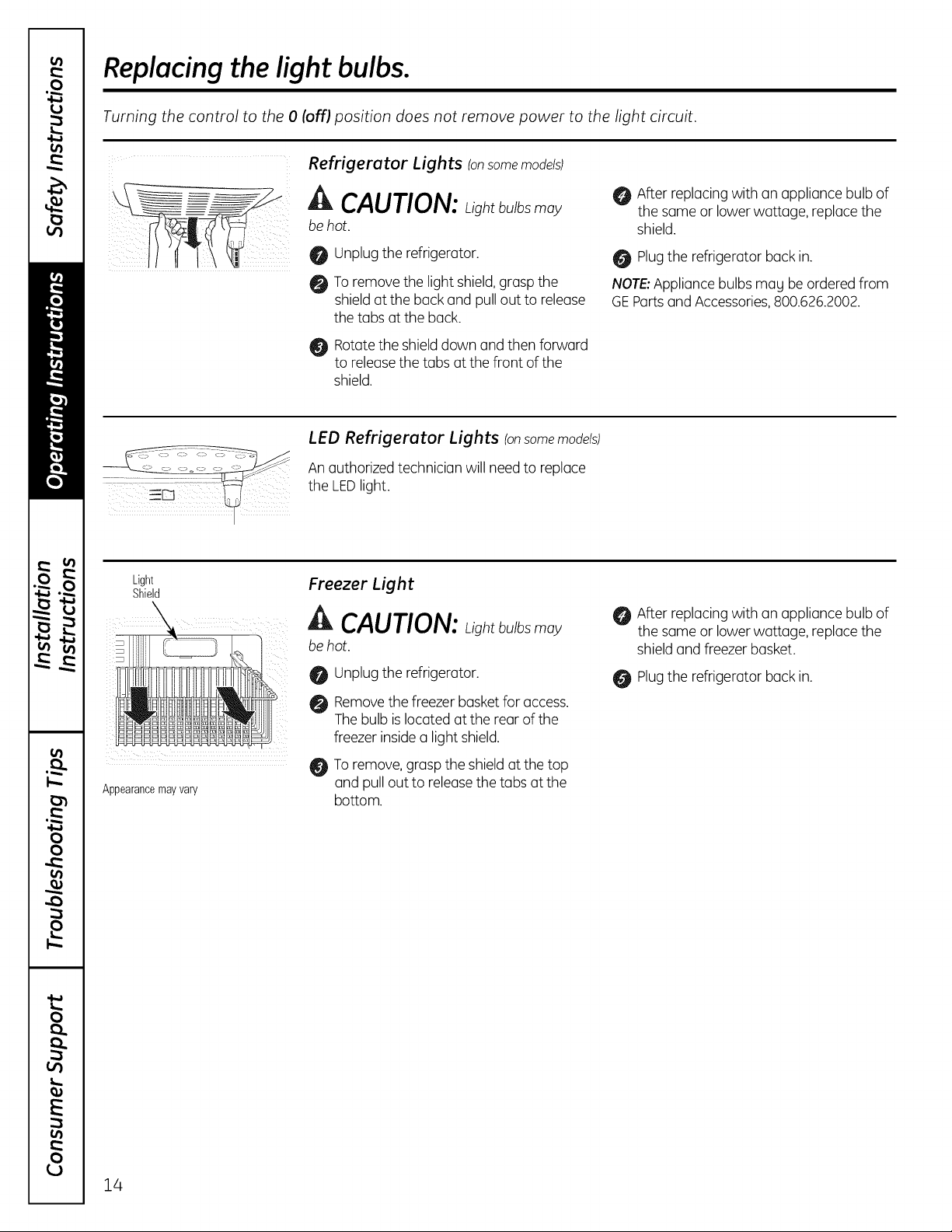
Replacing the light bulbs.
Turning the control to the 0 [off) position does not remove power to the light circuit.
Refrigerator Lights (onsomemodels)
Light
Shield
A CAUTION: Lightbu)b moy
be hot.
O Unplug the refrigerator.
To remove the light shield,graspthe
shieldat the back and pullout to release
the tabs at the back.
Rotatethe shield down and then forward
to releasethe tabs at the front of the
shield.
LED Refrigerator Lights (onsomemodels)
An authorized technician will need to replace
the LEDlight.
Freezer Light
CAUTION: Lightbulbs may
be hot.
After replacing with an appliance bulb of
the same or lower wattage, replacethe
shield.
Plugthe refrigerator back in.
NOTE'.Appliance bulbs mag be ordered from
GEPartsand Accessories,800.626.2002.
After replacing with an appliance bulb of
the same or lower wattage, replacethe
shield and freezer basket.
Appearancemayvary
Unplugthe refrigerator.
Removethe freezer basket for access.
Thebulb islocated at the rear of the
freezer inside a light shield.
To remove,grasp the shield at the top
and pull out to release the tabs at the
bottom.
Plugthe refrigerator back in.
14
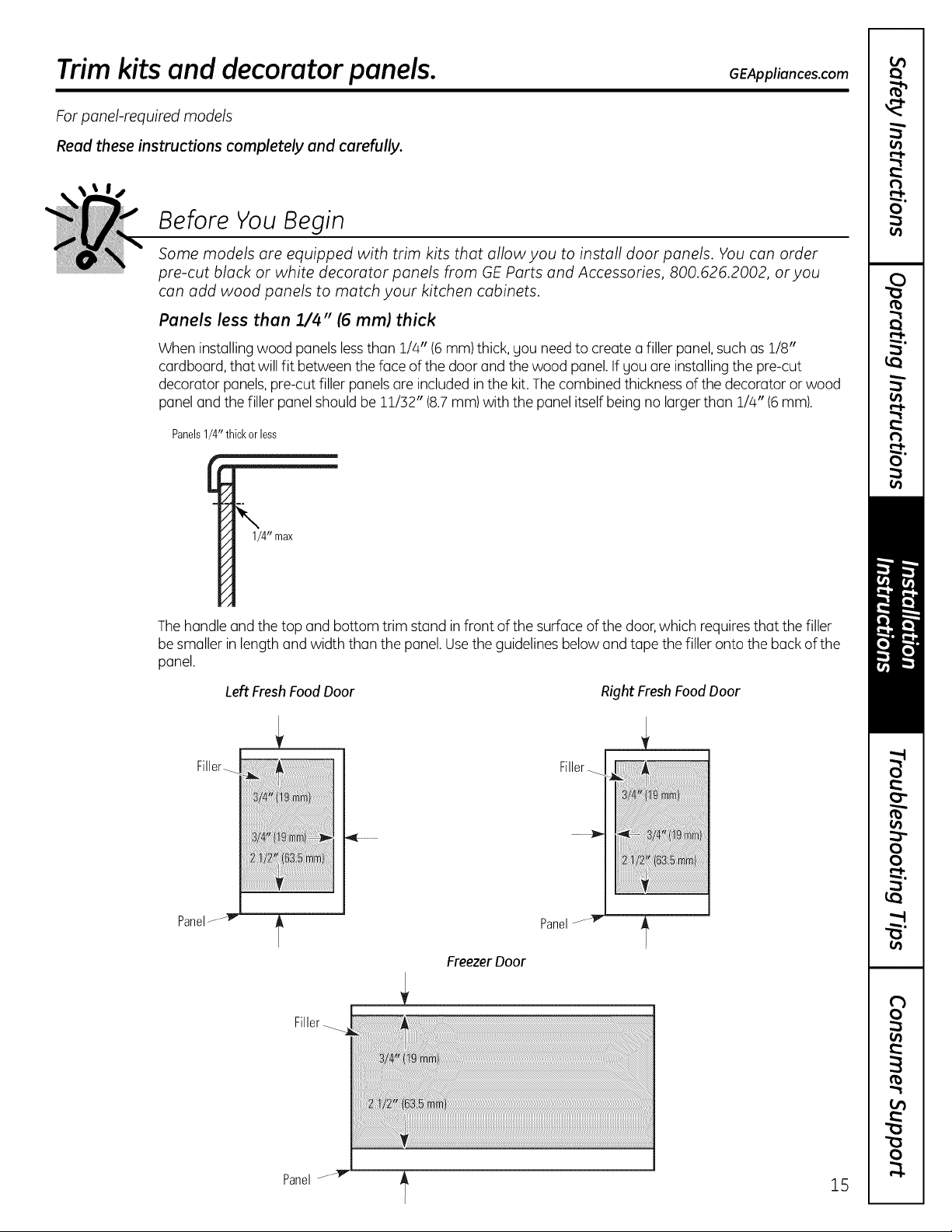
Trim kits and decorator panels.
For panel-required models
Read these instructions completely and carefully.
Before You Begin
Some models are equipped with trim kits that allow you to install door panels. You can order
pre-cut black or white decorator panels from GE Parts and Accessories, 800.626.2002, or you
can add wood panels to match your kitchen cabinets.
Panels less than 1//4" (6 mm) thick
When installing wood panels lessthan 114"(6 mm)thick, gou needto create a filler panel,suchas 118"
cardboard, that will fit between the face of the door and the wood panel.If SOUare installing the pre-cut
decorator panels,pre-cut filler panelsare included in the kit.Thecombined thickness ofthe decorator or wood
panel and the filler panel should be 11/32" (8.7mm) with the panel itself being no larger than 1/4" (6mm).
Panels1/4"thick orless
GEAppliances.com
1/4" max
/,
Thehandle and the top and bottom trim stand infront of the surface of the door,which requiresthat the filler
be smaller in length and width than the panel. Usethe guidelines below and tape the filler onto the back of the
panel.
Filler_
Panel
Left Fresh Food Door
Panel
Freezer Door
Filler
Right Fresh Food Door
Filler_
Panel_--
15
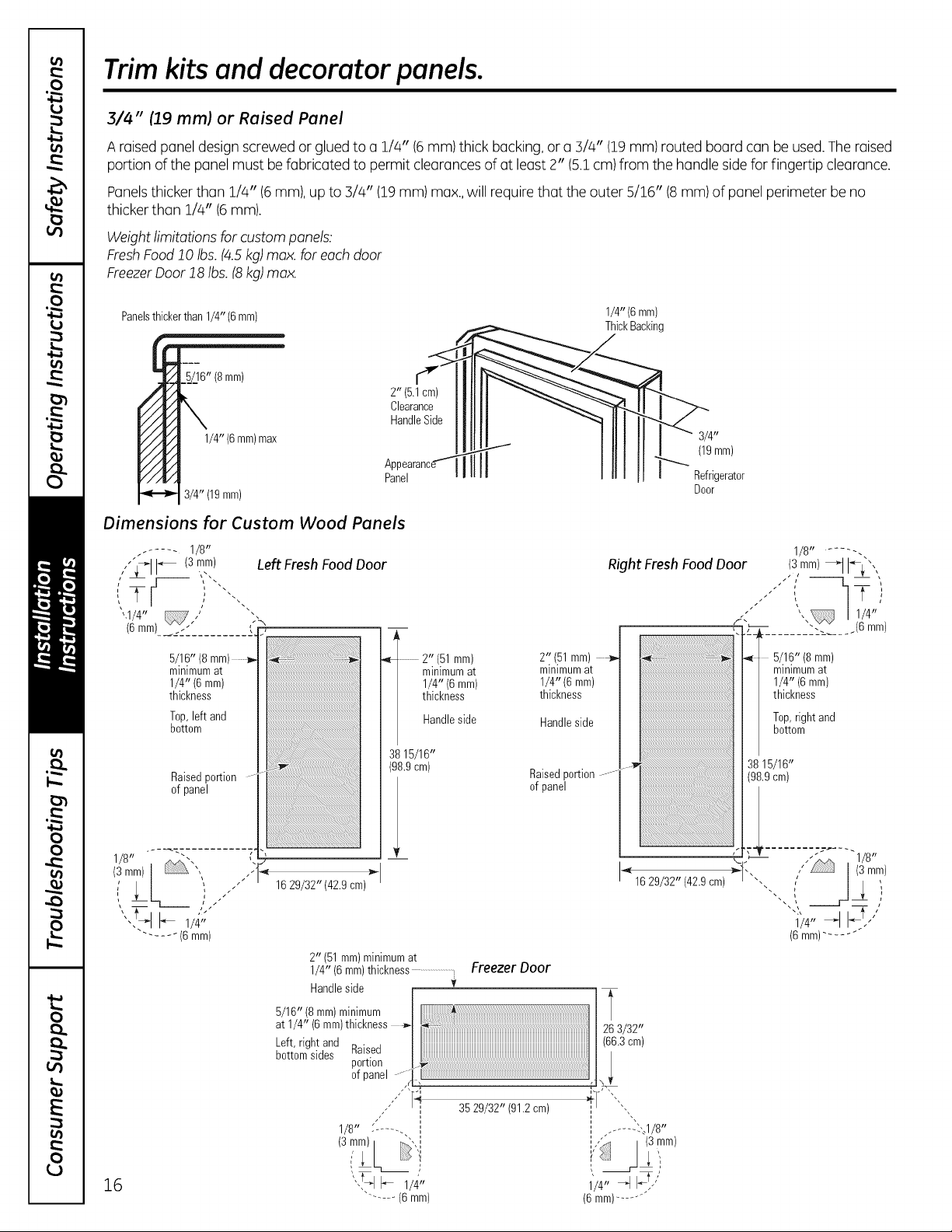
Trim kits and decorator panels.
3/4" (19 mm) or Raised Panel
A raised panel design screwed or glued to a 1/4" (6mm) thick backing, or a 3/4" (19mm)routed board can be used.Theraised
portion of the panel must be fabricated to permit clearancesof at least 2" (5.1cm) from the handle sidefor fingertip clearance.
Panelsthicker than 1/4" (6 mm), up to 3/4" (19 mm) max.,will require that the outer 5/16" (8 mm) of panel perimeter be no
thicker than 1/4" (6mm).
Weight limitations for custom panels:
FreshFood10 Ibs.(/4.5kg)max. for each door
FreezerDoor18 Ibs.18kg)max.
Panelsthickerthan1/4" (6mm)
6" (8mm)
1/4" (6mm)max
A
Panel
3/4" (19mm)
Dimensions for Custom Wood Panels
- ..... 1/8"
Left Fresh FoodDoor
,,"]_dI"_ 13.,_i_1
'.1/4" ,'
(6 mm)____<'" ........ !'.
5/16" (8 mm)
minimumat
1/4" (6 mm)
thickness
Top,left and
bottom
Raisedportion
of panel
_l!l_;_;_;_;_;_;_;_;_l_ii_ii_ii_ii_ii_ii_ii_ii_ii_ii_ii_ii_ii_ii_ii_ii_ii_ii_ii_ii_ii_ii_ii_ii_ii_ii_ii_ii_Jii!ii!ii!ii!ii!ii!ii!ii!!!!!_!i_!i_!i_!i_!i!!_!!_i_!iii
_b
2" (5.1cm)
Clearance
Handle Side
2" (51mm)
minimumat
1/4" (6mm)
thickness
Handleside
3815/16"
(98.9cm)
I
2" (51mm)
minimumat
1/4" (6 mm)
thickness
Handleside
Raisedportion
of panel
1/4" (6mm)
ThickBacking
3/4"
(19mm)
Refrigerator
Door
1/8........ .
Right FreshFoodDoor (3,mm)_1I'ff_',,,
,, 12-,
, ",, / 1/4"/
F .'-_r ....... -"-...... (6 mm)
i _i "_ 5/16"(8mm)minimumat
1/4" (6 mm)
thickness
Top,rightand
bottom
38 16/16"
(98.9cm)
l:<m'i-.....
...... (6 mm)
Z6
1629/32" (42.9 cm)
2" (51mm)minimumat
1/4" (6 mm)thickness ............................i
Handleside V
5/16" (8 mm)minimum
at 1/4" (6 mm)thickness
Left,right and
bottomsides Raised
portion
ofpanel
1/8" - ....... ',
....... (6mm)
Freezer Door
'H 3529/32" (91.2cm) _1"""-,
,, ,,
,, ....... .../
" I_!/
1/4" _'_
(6mm).......
(6mm)......
" 1 8"
Installation
Refrigerator
Instructions
Questions? Call 800.GE.CARES (800.432.2737) or visit our Website at: GEAppliances.com
In Canada, call 1.800.561.3344 or visit our Website at: www.GEAppliances.ca
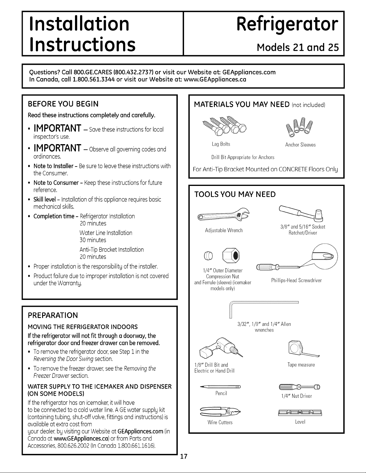
BEFORE YOU BEGIN
Readthese instructions completely and carefully.
MATERIALS YOU MAY NEED (notincluded)
Models 21 and 25
• IMPORTANT- savetheseinstructionsforlocal
inspector's use.
LagBolts
• IMPORTANT- Observeallgoverningcodesand
ordinances.
• Note to Installer- Besureto leavethese instructions with
the Consumer.
• Note to Consumer- Keepthese instructionsfor future
reference.
• Skill level- Installationof this appliance requires basic
mechanical skills.
• Completion time- RefrigeratorInstallation
20 minutes
Water Line Installation
30 minutes
For Anti-Tip Bracket Mounted on CONCRETEFloors Onlg
DrillBit AppropriateforAnchors
TOOLS YOU MAY NEED
AdjustableWrench
AnchorSleeves
3/8" and5/16" Socket
Ratchet/Driver
Anti-TipBracket Installation
20 minutes
• Properinstallation isthe responsibilitg ofthe installer.
• Productfailure due to improper installation isnot covered
under the Warrants.
PREPARATION
MOVING THE REFRIGERATOR INDOORS
If the refrigerator will not fit through a doorway, the
refrigerator door and freezer drawer can be removed.
• Toremove the refrigerator door,seeStep 1 in the
Reversingthe DoorSwingsection.
• Toremove the freezer drawer,seethe Removingthe
FreezerDrawer section.
WATER SUPPLY TO THE ICEMAKER AND DISPENSER
(ON SOME MODELS)
Ifthe refrigerator has an icemaker,itwill have
to beconnected to a cold water line.AGEwater supplgkit
(containingtubing, shut-off valve,fittings and instructions)is
availableat extra cost from
sour dealer,bg visiting our Websiteat GEAppliances.com(in
Canadaat www.GEAppliances.ca)orfrom Partsand
Accessories,800.626.2002(InCanada 1.800.661.1616).
1/4" OuterDiameter
CompressionNut
andFerrule(sleeve)(icemaker
modelsonly)
3/32", 1/8" and 1/4" Allen
1/8" Drill Bitand
ElectricorHandDrill
Pencil
WireCutters
Phillips-HeadScrewdriver
wrenches
Tapemeasure
1/4" Nut Driver
Level
17
Installation Instructions
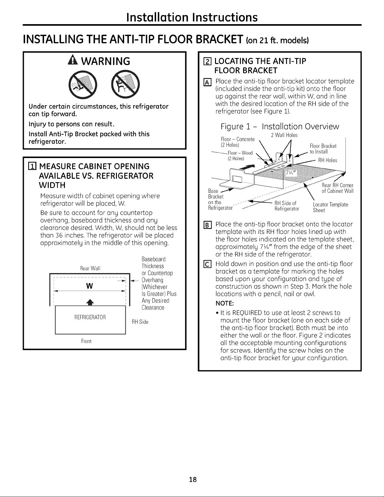
INSTALLING THE ANTI-TIP FLOOR
A WARNING
Under certain circumstances, this refrigerator
can tip forward.
Injury to persons can result.
Install Anti-Tip Bracket packed with this
refrigerator.
ITI MEASURE CABINET OPENING
AVAILABLE VS. REFRIGERATOR
WIDTH
Measure width of cabinet opening where
refrigerator will be placed, W.
Be sure to account for ang countertop
overhang, baseboard thickness and ang
clearance desired. Width, W, should not be less
than 36 inches. The refrigerator will be placed
oppro×imotelg in the middle of this opening.
Baseboard
RearWall
W
41,
REFRIGERATOR
Front
_I _ Overhang
..i (Whichever
Thickness
IsGreater)Plus
j orCountertop
AnyDesired
Clearance
RHSide
BRACKETIonzl ft.models)
LOCATING THE ANTI-TIP
FLOOR BRACKET
Place the anti-tip floor bracket Iocotor template
(included inside the anti-tip kit) onto the floor
up against the rear wall, within W, and in line
with the desired location of the RH side of the
refrigerator (see Figure 1).
Figure 1 - Installation Overview
2Wall Holes
Refrigerator _ Refrigerator Sheet
r_ Place the anti-tip floor bracket onto the Iocotor
template with its RH floor holes lined up with
the floor holes indicated on the template sheet,
opproximotelg 7½" from the edge of the sheet
or the RH side of the refrigerator.
r_ Hold down in position and use the anti-tip floor
bracket as o template for marking the holes
based upon gout configuration and tgpe of
construction as shown in Step 3. Mark the hole
locations with o pencil, nail or owl.
NOTE:
• It is REQUIREDto use otleast 2 screws to
mount the floor bracket (one on each side of
the anti-tip floor bracket). Both must be into
either the wall or the floor. Figure 2 indicates
oil the acceptable mounting configurations
for screws. Identifg the screw holes on the
anti-tip floor bracket for gout configuration.
18
Installation Instructions
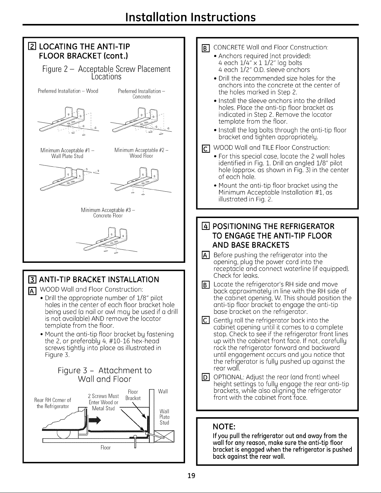
r_l LOCATING THE ANTI-TIP
FLOOR BRACKET (cont.)
Figure2- Acceptabl.eScrewPlacement
Locations
PreferredInstallation- Wood PreferredInstallation-
MinimumAcceptable#1-
Wall PlateStud
MinimumAcceptable#3 -
ConcreteFloor
[] ANTI-TIP BRACKET INSTALLATION
_] WOOD Wall and Floor Construction:
• Drill the appropriate number of 1/8" pilot
holes in the center of each floor bracket hole
being used (o nail or awl mag be used if a drill
is not available) AND remove the Iocator
template from the floor.
• Mount the anti-tip floor bracket bg fastening
the 2, or preferablg 4, #10-16 hex-head
screws tightlg into place as illustrated in
Figure 3.
Concrete
MinimumAcceptable#2-
WoodFloor
Figure 3 - Attachment to
Wall and Floor
Floor Wall
RearRHCornerof
the Refrigerator
2 ScrewsMust Bracket
EnterWoodor
MetalStud
Floor
Wall
Plate
Stud
r_ CONCRETE Wall and Floor Construction:
• Anchors required (not provided):
4 each 1/4" x 1 1/2" lag bolts
4 each 1/2" O.D. sleeve anchors
• Drill the recommended size holes for the
anchors into the concrete at the center of
the holes marked in Step 2.
• Install the sleeve anchors into the drilled
holes. Place the anti-tip floor bracket as
indicated in Step 2. Remove the Iocotor
template from the floor.
• Install the lag bolts through the anti-tip floor
bracket and tighten oppropriatelg.
[] WOOD Wall and TILE Floor Construction:
• For this special case, locate the 2 wall holes
identified in Fig. 1. Drill an angled 1/8" pilot
hole (approx. as shown in Fig. 3)in the center
of each hole.
• IVlount the anti-tip floor bracket using the
IVlinimum Acceptable Installation #1, as
illustrated in Fig. 2.
ra
POSITIONING THE REFRIGERATOR
TO ENGAGE THE ANTI-TIP FLOOR
AND BASE BRACKETS
rA-]
Before pushing the refrigerator into the
opening, plug the power cord into the
receptacle and connect waterline (if equipped).
Check for leaks.
Locate the refrigerator's RHside and move
back opproximotelg in line with the RH side of
the cabinet opening, W. This should position the
anti-tip floor bracket to engage the anti-tip
base bracket on the refrigerator.
D
Gentlg roll the refrigerator back into the
cabinet opening until it comes to o complete
stop. Check to see if the refrigerator front lines
up with the cabinet front face. If not, corefullg
rock the refrigerator forward and backward
until engagement occurs and gou notice that
the refrigerator is fullg pushed up against the
rear wall.
@
OPTIONAL: Adjust the rear (and front) wheel
height settings to fullg engage the rear anti-tip
brackets, while also aligning the refrigerator
front with the cabinet front face.
NOTE:
If you pull the refrigerator out and away from the
wall for any reason, make sure the anti-tip floor
bracket is engaged when the refrigerator is pushed
back against the rear wall.
19
Installation Instructions
INSTALLING THE REFRIGERATOR
REFRIGERATOR LOCATION
• Do not installthe refrigerator where the temperature will
go below 60°F(16°C)because it will not run oftenenough
to maintain proper temperatures.
• Do not installthe refrigerator where the temperature will
go above IO0°F(37°C)becauseit will not perform properly.
• Installit on a floor strong enough to support it fully loaded.
CLEARANCES
Allowthe following clearancesfor easeof installation,proper
air circulation and plumbing and electrical connections.
Standard Depth Counter Depth
Models Models
Sides 1/8" (3mm) 1/8" (3mm)
Top 1" (25mm) 1" (25mm)
Back 1" (25mm) 1/2" (13mm)
REMOVE TOP CAP (on some models)
• IMPORTANTNOTE:This refrigerator is 34-1/2" deep.
Doors and passageways leading to the installation
location must be at least 36" wide in order to leave the
doors and handles attached to the refrigerator while
transporting it into the installation location. If
passageways are lessthan 36", the refrigerator doors
and handles can easily be scratched and damaged.
Thetop cap anddoors can be removedto allow the
refrigerator to be safely moved indoors. Start with StepA.
• If it is not necessary to remove doors, skip Step A. Leave
tape and allpackaging on doors until the refrigerator is
in the final location.
•SKIDREMOVAL:Tilt refrigerator to each side to remove
skid.
• NOTE:Usea padded hand truck to move this refrigerator.
Placethe refrigerator on the hand truck with a side
againstthe truck. We strongly recommend that TWO
PEOPLEmove and complete this installation.
[] Locuteund remove the two Phillipsheud screws on the
top ofthe refrigerator. Removethe two screws on each
sideat the rear of the top cup.
Liftoff and remove top cup.
[] Removethe fresh-food door. Referto Steps 1through 3
of "Reversingthe DoorSwing"section.
[] Removethe bottom freezer drawer. Referto "Removing
FreezerDrawer"section.
FDI Moverefrigerator to the installation locution.
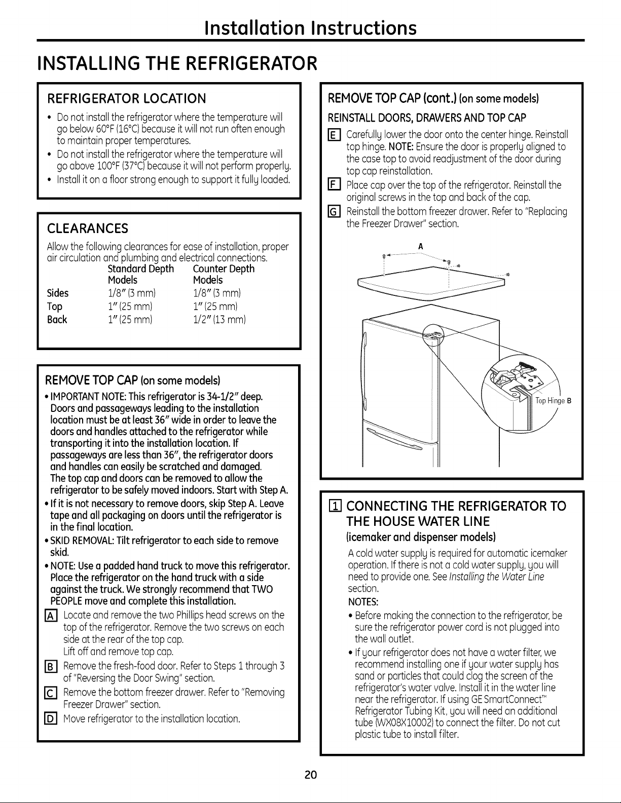
REMOVETOPCAP{cont.)(onsome models)
REINSTALLDOORS,DRAWERSAND TOPCAP
r_ Carefullg lowerthe door onto the center hinge. Reinstall
top hinge.NOTE:Ensurethe door isproperly aligned to
the case top to avoid readjustment of the door during
top cup reinstallation.
r_ Placecup overthe top of the refrigerator. Reinstallthe
original screws in the top and buck of the cup.
Reinstallthe bottom freezer drawer. Referto "Replacing
the FreezerDrawer"section.
A
Top Hinge B
rrl CONNECTING THE REFRIGERATOR TO
THE HOUSE WATER LINE
(icemaker and dispenser models)
A coldwater supply isrequiredfor automatic icemaker
operation. If there isnot a coldwater supply,you will
need to provideone.SeeInstolling theWaterLine
section.
NOTES:
• Beforemaking the connectionto the refrigerator, be
surethe refrigerator power cord is not plugged into
the wall outlet.
• If your refrigerator does not have a water filter, we
recommend installing one if your water supply has
sandor particlesthat couldclog the screen of the
refrigerator'swater valve. Installit in the water line
near the refrigerator. If usingGESmartConnect_"
RefrigeratorTubing Kit, you will need an additional
tube (WXO8XIO002)to connect the filter. Do not cut
plastictube to installfilter.
20
Installation Instructions
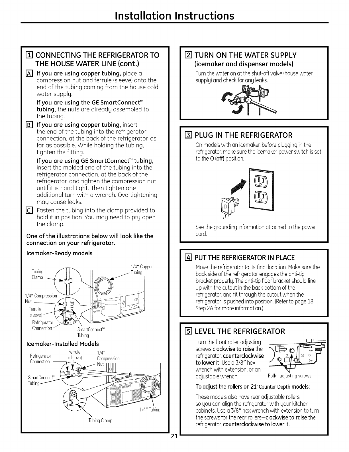
m CONNECTING THE REFRIGERATOR TO
THE HOUSE WATER LINE (cont.)
[] If you are using copper tubing, place a
compression nut and ferrule (sleeve) onto the
end of the tubing coming from the house cold
water supplg.
If you are using the GE SmartConnect TM
tubing, the nuts are alreadg assembled to
the tubing.
['_ If you are using copper tubing, insert
the end of the tubing into the refrigerator
connection, at the back of the refrigerator, as
far as possible. While holding the tubing,
tighten the fitting.
If you are using GE SmartConnect'" tubing,
insert the molded end of the tubing into the
refrigerator connection, at the back of the
refrigerator, and tighten the compression nut
until it is hand tight. Then tighten one
additional turn with a wrench. Overtightening
mag cause leaks.
r_ Fasten the tubing into the clamp provided to
hold it in position. You mag need to prg open
the clamp.
One of the illustrations below will look like the
connection on your refrigerator.
r_l TURN ON THE WATER SUPPLY
(icemaker and dispenser models)
Turnthe water on atthe shut-off valve (housewater
supply)and check for any leaks.
[] PLUG IN THE REFRIGERATOR
On models with an icemaker,before plugging in the
refrigerator,make surethe icemaker power switch isset
to the 0 loft} position.
Seethe grounding information attached to the power
cord.
Icemaker-Ready models
Tubing /
Clamp_
1/4" Compression
Nut _
Ferrule f'_
(sleeve)_
Refrigerator
Connection/
Icemaker-lnstalled Models
Refrigerator (sleeve) Compression
Connection-- Nut
SmartConnect_
SmartConnectT_
Tubing
Ferrule 1/4"
TubingClamp
1/4" Copper
I/4"Tubing
[] PUTTHE REFRIGERATORIN PLACE
Hove the refrigerator to its final location.Hake surethe
back sideof the refrigerator engagesthe anti-tip
bracket properlg. Theanti-tip floor bracket should line
up with the cutout inthe backbottom of the
refrigerator,and fit through the cutout when the
refrigerator is pushed into position.(Referto page 18,
Step2Afor more information.)
rsl LEVEL THE REFRIGERATOR
Turnthe front roller adjusting
screws clockwise to raisethe
refrigerator,counterclockwise
to lower it. Usea 3/8" hex
wrench with extension,or an
adjustable wrench.
Toadjust the rollers on 21' CounterDepthmodels:
Thesemodels alsohave rear adjustable rollers
so gou can align the refrigerator with gour kitchen
cabinets. Usea B/8" hexwrench with extension to turn
the screws for the rear rollers-clockwise to raise the
refrigerator,counterclockwise to lower it.
Rolleradjustingscrews
21

Installation Instructions
INSTALLING THE REFRIGERATOR(cont.)
161REMOVE THE FRESH FOOD
DOOR HANDLE
(For placement in the installation location or
reversal of the handles - on some models)
stainless steel (on some models):
@ REMOVING
THEDOORHANDLE:
Loosenthe set screws
with the 3/32" Allen
wrench
and remove
the handle. NOTE:For
Double Door models
follow the same
procedure on the
opposite door.
Mounting /
Fasteners
(appearancemay vary)
Plastic handle (on some models):
0 REMOVINGTHEDOORHANDLE:Depressthe tab on
the underside of the handle and slidethe handle up
and off of the mounting fasteners.
@ REVERSINGTHEDOORHANDLE(onsome models):
• Remove
the handle
mounting ..
rTi REMOVE THE FREEZER DOOR HANDLE
Stainless steel and plastic handles:
@ Loosenthe set screws located on the underside of
the handle with a 1/8" or 3/32" Allenwrench and
remove the handle.
NOTE:Ifthe handle mounting fastenersneedto be
tightened or removed,usea 1/4" Allenwrench.
Badge
fasteners with fa 1/4" Allen
wrench and Badge
transfer the
handle
mounting
fasteners to the
right side.
• Removethe logo
badge. Mounting
• Removeand
transfer the (appearancemay vary)
plug button to
the left sideof the freshfood door. NOTE:Usea flat
plasticedge to prevent damaging the door.Remove
any adhesiveon the door with a mild detergent.
Removethe paper covering on the adhesive
backing on the logo badge prior to carefully
attaching the badge to the door.
Fasteners
22
Installation Instructions
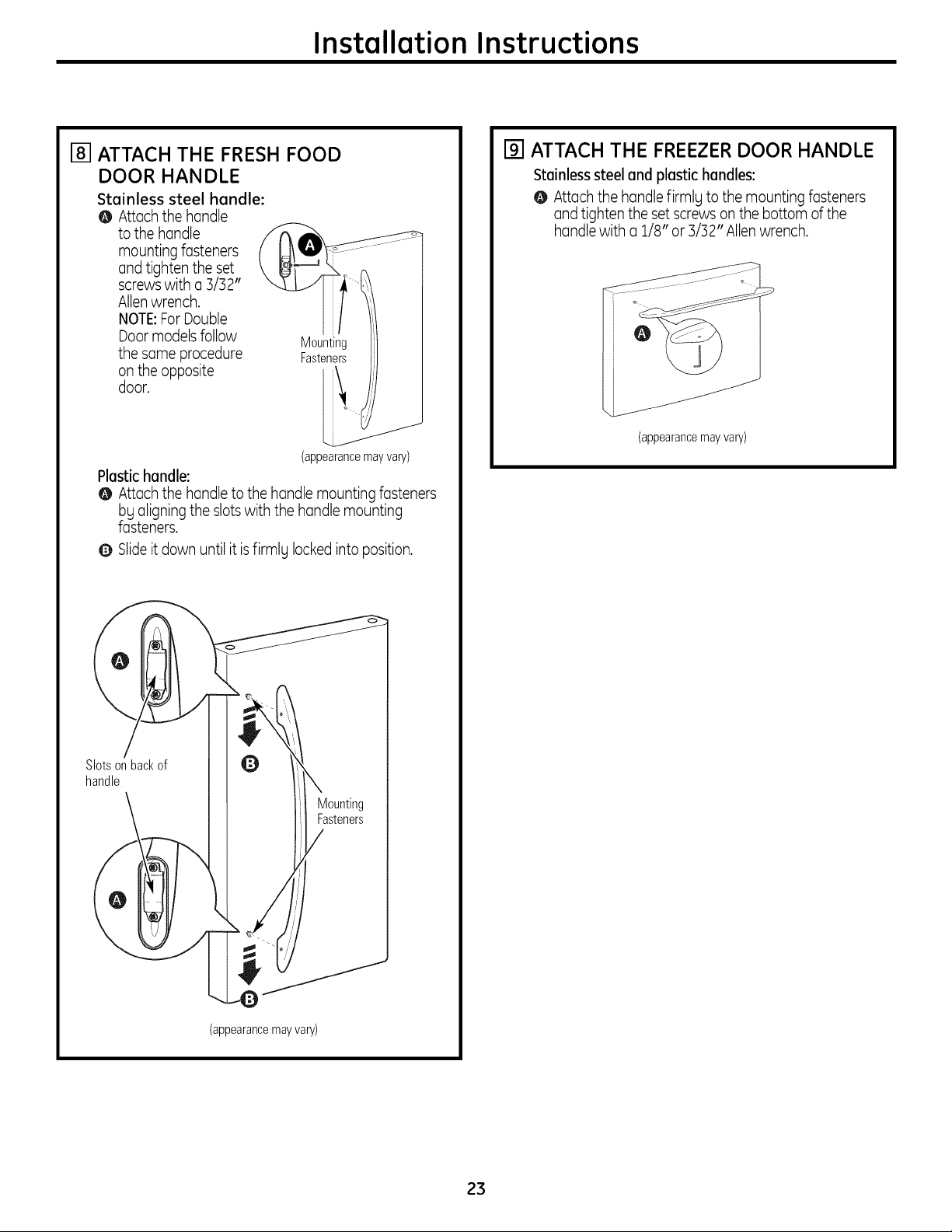
[] ATTACH THE FRESH FOOD
DOOR HANDLE
Stainless steel handle:
@ Attach the handle
to the handle
mounting fasteners
and tighten the set
screwswith a 3/32"
Allenwrench.
NOTE:ForDouble
Door modelsfollow
the same procedure
on the opposite
door.
Plastic handle:
@ Attach the handleto the handle mountingfasteners
bg aligning the slots with the handlemounting
fasteners.
Q Slideit down until it isfirmlg locked into position,
Mounting
Fasteners
(appearance mayvary)
[] ATTACH THE FREEZER DOOR HANDLE
Stainless steel and plastic handles:
@ Attach the handle firmlg to the mounting fasteners
and tighten the set screwson the bottom of the
handle with a 1/8" or 3/32" Allenwrench.
(appearancemay vary)
Slotsonbackof
handle
__X_Mounting
/J Fasteners
(appearancemayvary)
23
Installation Instructions
INSTALLING THE REFRIGERATOR(cont.)
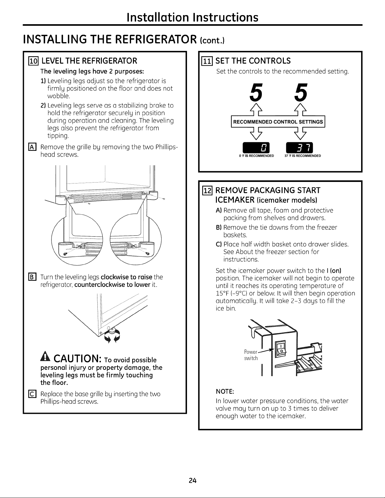
LEVEL THE REFRIGERATOR
The leveling legs have 2 purposes:
1) Leveling legs adjust so the refrigerator is
firmlg positioned on the floor and does not
wobble.
2) Leveling legs serve as a stabilizing brake to
hold the refrigerator securelg in position
during operation and cleaning. The leveling
legs also prevent the refrigerator from
tipping.
[_] Remove the grille bg removing the two Phillips-
head screws.
SET THE CONTROLS
Set the controls to the recommended setting.
5 5
47
IRECOMMENDEDCONTROLSETTINGS]
0 °F IS RECOMMENDED 37 °F IS RECOMMENDED
[_] REMOVE PACKAGING START
ICEMAKER (icemaker models)
A) Remove all tape, foam and protective
packing from shelves and drawers.
B) Remove the tie downs from the freezer
baskets.
C) Place half width basket onto drawer slides.
See About the freezer section for
instructions.
r_ Turn the leveling legs clockwise to raise the
refrigerator, counterclockwise to lower it.
Ik CAUTION: To avoid possible
personal injury or property damage, the
leveling legs must be firmly touching
the floor.
r_ Replace the base grille bg inserting the two
Phillips-head screws.
Set the icemaker power switch to the I (on)
position. The icemuker will not begin to operate
until it reaches its operating temperature of
15°F (-9°C) or below. It will then begin operation
uutomuticullg. It will take 2-3 dugs to fill the
ice bin.
NOTE:
In lower water pressure conditions, the water
valve mug turn on up to 3 times to deliver
enough water to the icemoker.
24
Installation Instructions
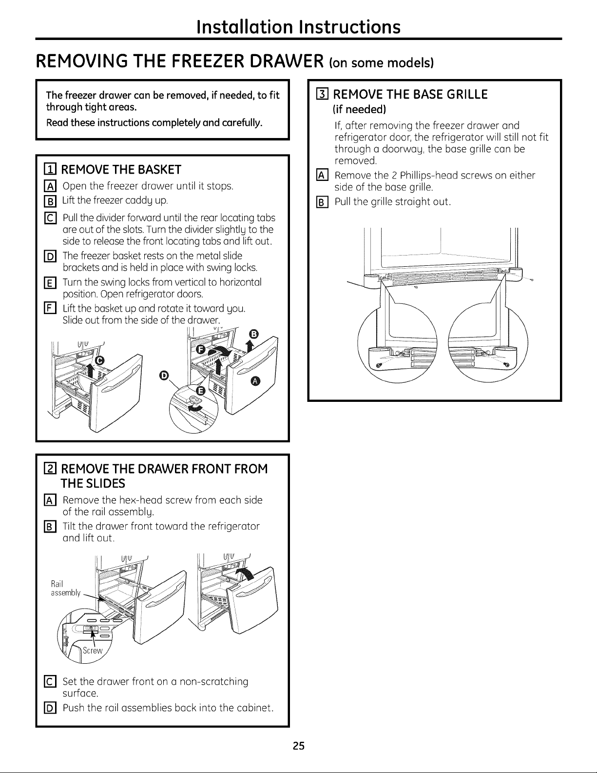
REMOVING THE FREEZER DRAWER (on some models}
The freezer drawer can be removed, if needed, to fit
through tight areas.
Read these instructions completely and carefully.
ITI REMOVE THE BASKET
r_ open the freezer drawer until it stops.
r_ Lift the freezer caddg up.
r_ pull the divider forward until the rear locating tabs
are out of the slots. Turn the divider slightlg to the
side to release the front locating tabs and lift out.
r_ The freezer basket rests on the metal slide
brackets and is held in place with swing locks.
r_ Turn the swing locks from vertical to horizontal
position. Open refrigerator doors.
r_ Lift the basket up and rotate it toward gou.
Slide out from the side of the drawer.
[] REMOVE THE BASE GRILLE
(if needed)
If, after removing the freezer drawer and
refrigerator door, the refrigerator will still not fit
through a doorwag, the base grille can be
removed.
_] Remove the 2 Phillips-head screws on either
side of the base grille.
_] Pull the grille straight out.
o
I_1 REMOVE THE DRAWER FRONT FROM
THE SLIDES
IA1 Remove the hex-head screw from each side
of the rail assemblg.
FB1 Tilt the drawer front toward the refrigerator
and lift out.
Rail
assembly
\
r_ set the drawer front on a non-scratching
surface.
[] Push the rail assemblies back into the cabinet.
25
Installation Instructions
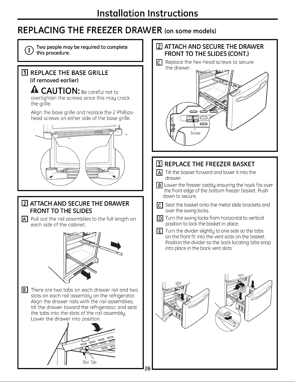
REPLACING THE FREEZER DRAWER (on some models}
Two people may be required to complete
this procedure.
m REPLACE THE BASE GRILLE
(if removed earlier)
CAUTION: Becorefulnotto
overtighten the screws since this mag crack
the grille.
Align the base grille and replace the 2 Phillips-
head screws on either side of the base grille.
r2l ATTACH AND SECURETHE DRAWER
FRONT TO THE SLIDES
_-l Pull out the rail assemblies to the full length on
each side of the cabinet.
[] ATTACH AND SECURE THE DRAWER
FRONT TO THE SLIDES (CONT.)
[] Replace the hex-head screws to secure
the drawer.
r31REPLACE THE FREEZER BASKET
r-_ Tilt the basket forward and lower it into the
drawer.
r_ Lower the freezer caddg ensuring the hook fits over
the front edge of the bottom freezer basket. Push
down to secure.
rc1 seat the basket onto the metal slide brackets and
over the swing locks.
[] Turn the swing locks from horizontal to vertical
position to lock the basket in place.
r_ Turn the divider slightlg to one side so the tabs
on the front fit into the vent slots on the basket.
Position the divider so the back locating tabs snap
into place in the back vent slots.
\
rB1 There are two tabs on each drawer rail and two
slots on each rail assemblLl on the refrigerator.
Align the drawer rails with the rail assemblies,
tilt the drawer toward the refrigerator, and seat
the tabs into the slots of the rail assemblg.
Lower the drawer into position.
Slot Tab
\
26
Installation Instructions
REVERSINGTHE DOORSWING (Single Door Refrigerator Models only)
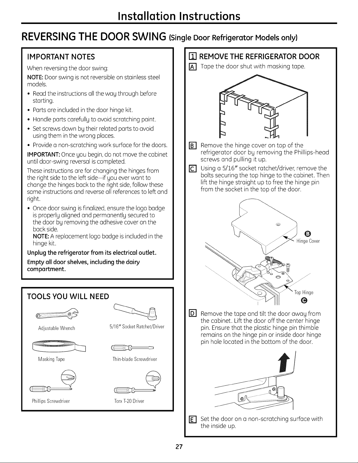
IMPORTANT NOTES
When reversing the door swing:
NOTE:Door swing is not reversible on stainless steel
models.
• Read the instructions all the wag through before
starting.
• Ports are included in the door hinge kit.
• Handle parts carefullg to avoid scratching paint.
• Setscrews down bgtheir related partsto avoid
usingthem in the wrong places.
• Provide a non-scratching work surface for the doors.
IMPORTANT: Once gou begin, do not move the cabinet
until door-swing reversal is completed.
These instructions are for changing the hinges from
the right side to the left side-if gou ever want to
change the hinges back to the right side, follow these
same instructions and reverse all references to left and
right.
• Once door swing isfinalized, ensure the logo badge
is properlg aligned and permanentlg secured to
the door bg removing the adhesive cover on the
back side.
NOTE: A replacement logo badge is included in the
hinge kit.
Unplug the refrigerator from its electrical outlet.
Empty all door shelves, including the dairy
compartment.
ITI REMOVE THE REFRIGERATOR DOOR
I_] Tape the door shut with masking tape.
FB1 Remove the hinge cover on top of the
refrigerator door bg removing the Phillips-head
screws and pulling it up.
rc1 using a 5/16" socket ratchet/driver, remove the
bolts securing the top hinge to the cabinet. Then
lift the hinge straight up to free the hinge pin
from the socket in the top of the door.
TOOLS YOU WILL NEED
AdjustableWrench 5/16" SocketRatchet/Driver
MaskingTape Thin-bladeScrewdriver
PhillipsScrewdriver
TorxT-20Driver
BI
Remove the tape and tilt the door awag from
the cabinet. Lift the door off the center hinge
pin. Ensure that the plastic hinge pin thimble
remains on the hinge pin or inside door hinge
pin hole located in the bottom of the door.
rE1 Set the door on a non-scratching surface with
the inside up.
27
Installation Instructions
REVERSINGTHE DOORSWING (cont.)
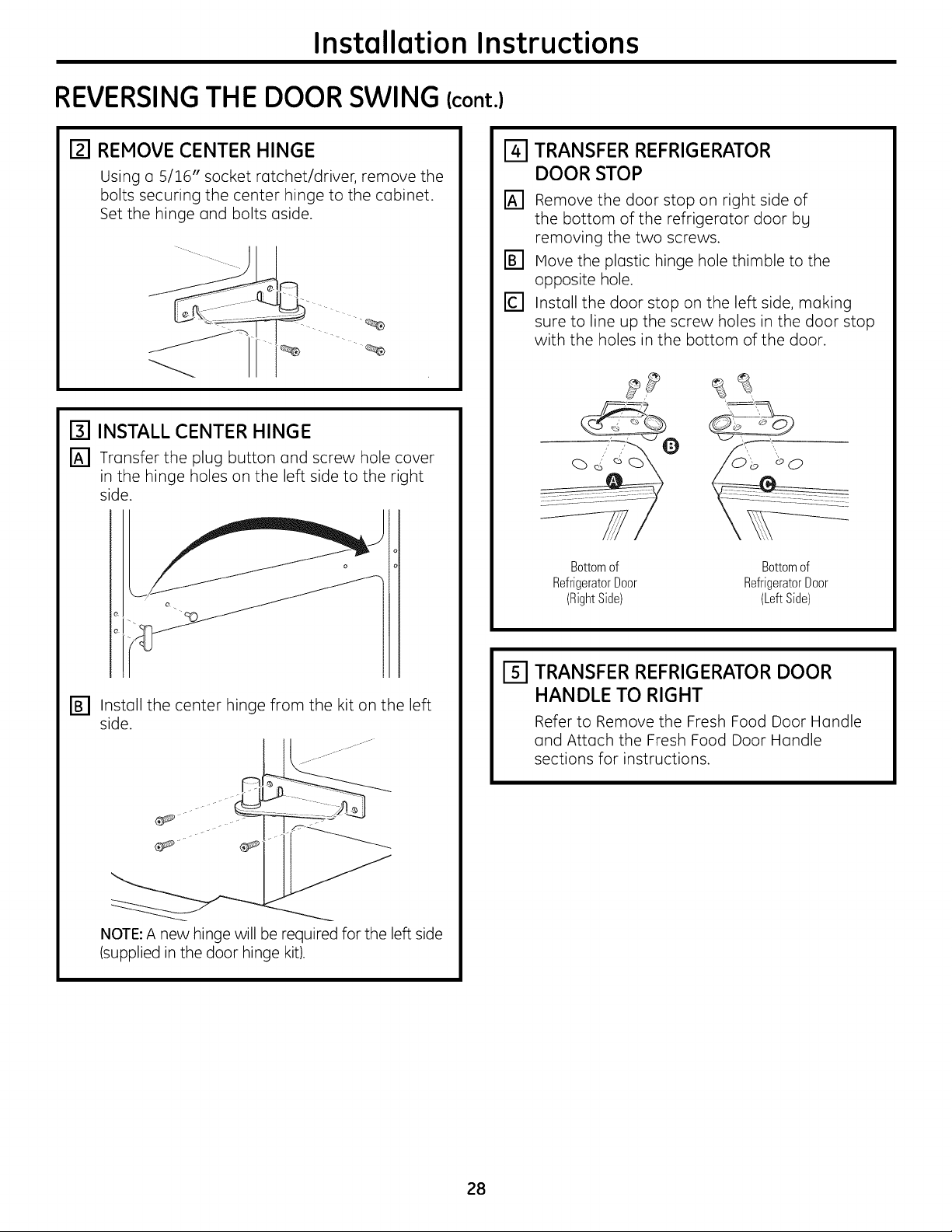
rzl REMOVE CENTER HINGE
Using o 5/16" socket rotchet/driver, remove the
bolts securing the center hinge to the cobinet.
Set the hinge ond bolts oside.
[] INSTALL CENTER HINGE
[_] Tronsfer the plug button ond screw hole cover
in the hinge holes on the left side to the right
side.
o
o
e_
o
TRANSFER REFRIGERATOR
DOOR STOP
[]
Remove the door stop on right side of
the bottom of the refrigerotor door bg
removing the two screws.
Move the plostic hinge hole thimble to the
opposite hole.
Install the door stop on the left side, making
sure to line up the screw holes in the door stop
with the holes in the bottom of the door.
Bottomof Bottomof
RefrigeratorDoor RefrigeratorDoor
(RightSide) (LeftSide)
r_ Instoll the center hinge from the kit on the left
side.
NOTE:A new hinge will be required for the left side
(supplied in the door hinge kit).
_-I TRANSFER REFRIGERATOR DOOR
HANDLE TO RIGHT
Refer to Remove the Fresh Food Door Handle
and Attach the Fresh Food Door Handle
sections for instructions.
28
Installation Instructions
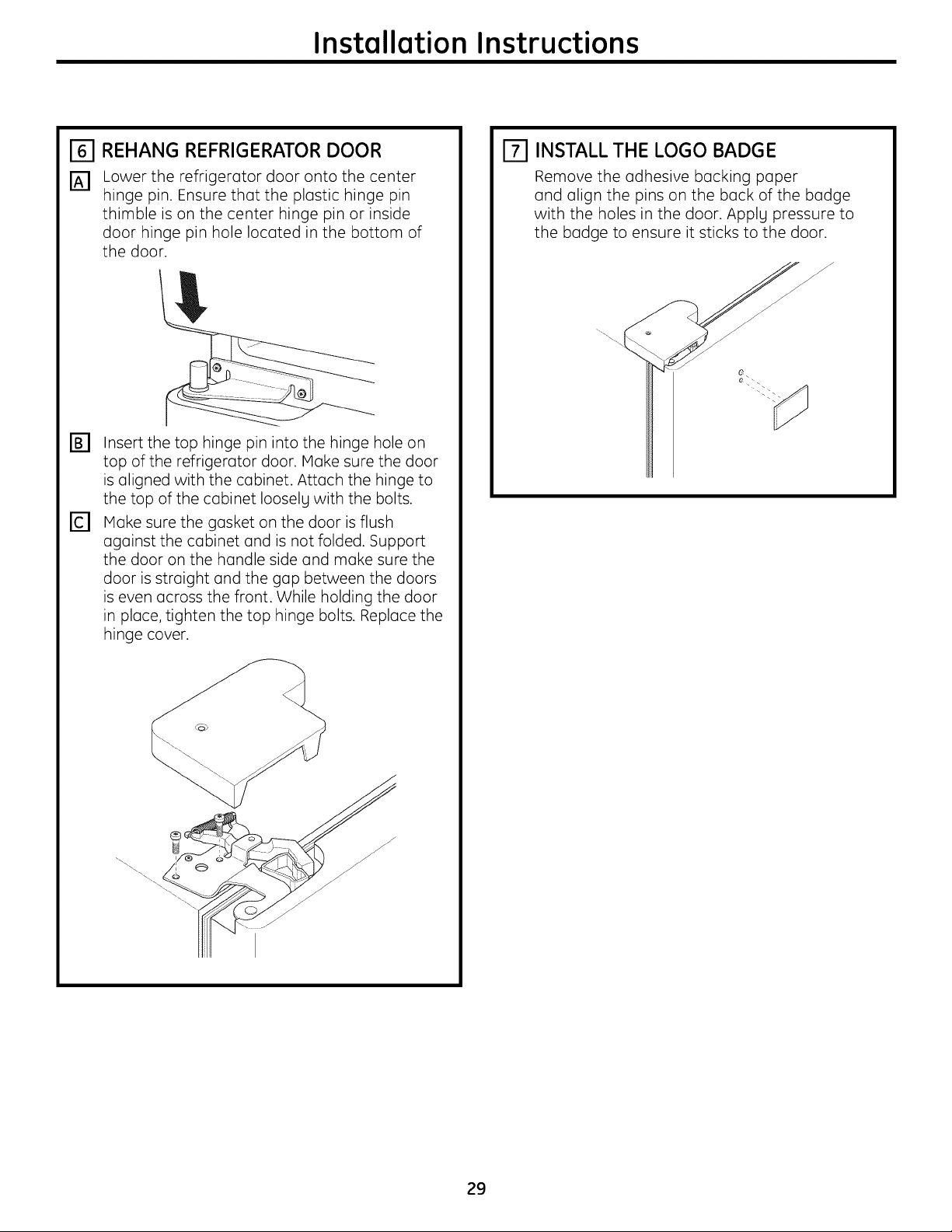
REHANG REFRIGERATOR DOOR
[_] Lower the refrigerator door onto the center
hinge pin. Ensure that the plastic hinge pin
thimble is on the center hinge pin or inside
door hinge pin hole located in the bottom of
the door.
E]
Insert the top hinge pin into the hinge hole on
top of the refrigerator door. Make sure the door
is aligned with the cabinet. Attach the hinge to
the top of the cabinet Iooselg with the bolts.
re]
Make sure the gasket on the door is flush
against the cabinet and is not folded. Support
the door on the handle side and make sure the
door is straight and the gap between the doors
is even across the front. While holding the door
in place, tighten the top hinge bolts. Replace the
hinge cover.
INSTALL THE LOGO BADGE
Remove the adhesive backing paper
and align the pins on the back of the badge
with the holes in the door. Applg pressure to
the badge to ensure it sticks to the door.
j
0
29
Installation Instructions
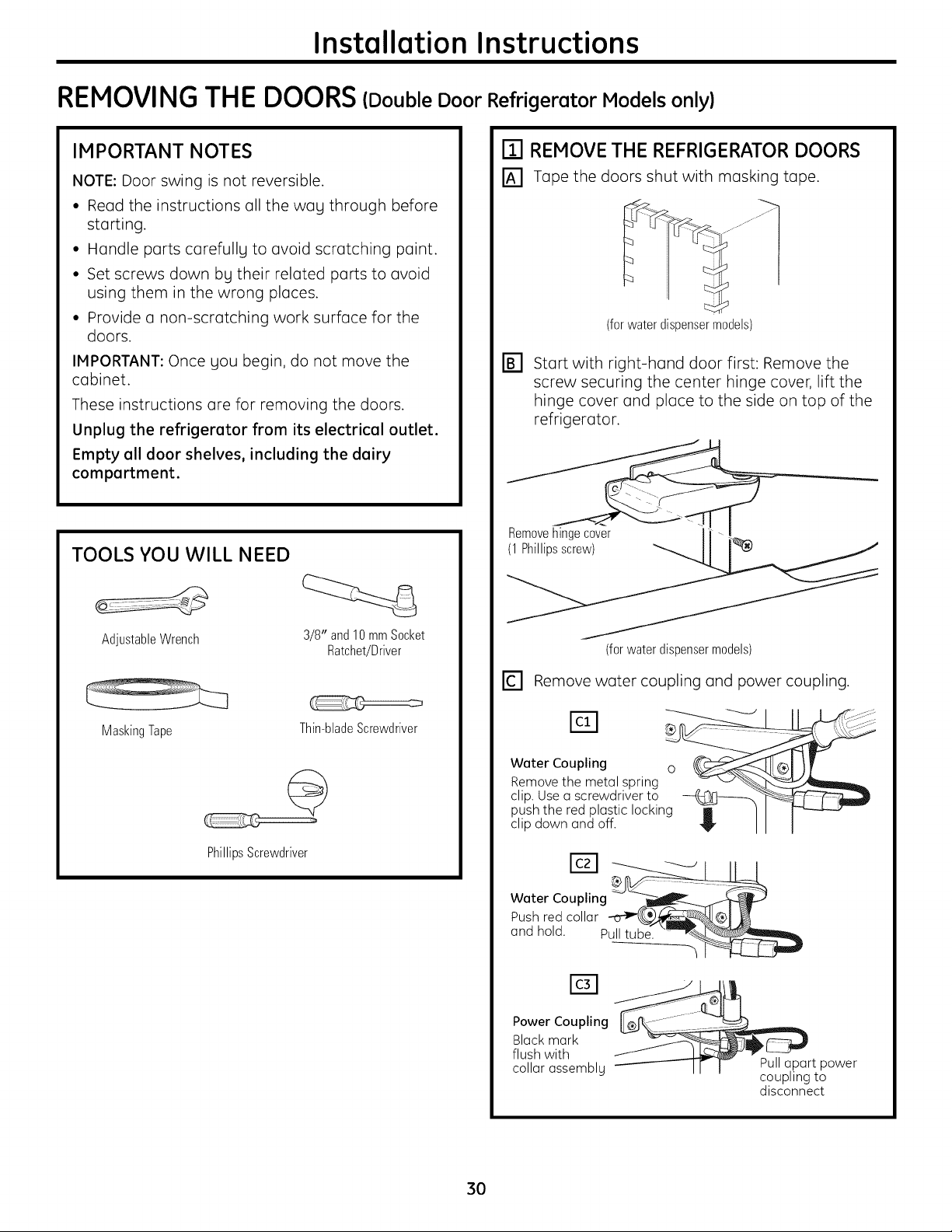
REMOVINGTHE DOORS(Double Door Refrigerator Models only)
IMPORTANT NOTES
NOTE: Door swing is not reversible.
• Read the instructions all the way through before
starting.
• Handle ports carefully to ovoid scratching point.
• Set screws down by their related ports to ovoid
using them in the wrong places.
• Provide a non-scratching work surface for the
doors.
IMPORTANT: Once you begin, do not move the
cabinet.
These instructions are for removing the doors.
Unplug the refrigerator from its electrical outlet.
Empty all door shelves, including the dairy
compartment.
TOOLS YOU WILL NEED
ITl REMOVE THE REFRIGERATOR DOORS
[] Tape the doors shut with masking tape.
(for water dispenser models)
D Start with right-hand door first: Remove the
screw securing the center hinge cover, lift the
hinge cover and place to the side on top of the
refrigerator.
Remove
AdjustableWrench
MaskingTape
Thin-bladeScrewdriver
PhillipsScrewdriver
3/8" and 10mmSocket
Ratchet/Driver
(for water dispenser models)
rc1 Remove water coupling and power coupling.
Water Coupling o __,01 )[
Remove the metal spring _ __
clip. Use a screwdriver to __,__
push the red plastic locking _ / I _-__
clip down and off. "_" I I I
Power Coupling
Black mark
flush with
collar assembly
Pull apart power
coupling to
disconnect
3O
 Loading...