


FSE 450
SERVICE MANUAL
SERVICE MANUAL
MOTOR FSE400 / 450
MOTOR FSE400 / 450
2002 / 2003
2002 / 2003

Contents
Technical Specifications.....................................................84
Engine Removal and Installation.......................................86
Engine Disassembly..................................................…....96
Inspection and Maintenance
of Engine Components......................................................108
Engine Installation................................................................136
Regular Maintenance............................................................156

Technical Specifications
MODEL
Ec 400 / 450 FSE
ENGINE
Cubic Capacity
Type
Number of Cylinders
Cooling System
Bore and Stroke
Injection
Ignition
Clutch
Gearbox
399 cc. / 449 cc.
4-stroke with 4-valve cylinder head
One
Water-cooled
90 x 62.6 mm. / 95 x 62.6 mm.
E.F.I. Magneti Marelli Electronic Fuel
Injection System
E.F.I. integrated
Hydraulic-drive disc clutch
6 Gears
FRAME
Type of Frame
Front Suspension
Rear Suspension
Front Brake
Rear Brake
Wheels
Deltabox, made from Cromoly rectangular tubes
Aluminium Rocker
Inverted WP
Inverted Marzocchi
Inverted Öhlins
Progressive System fitted with Ohlins Shock-Absorber
320-mm Stroke
260-mm Disc
Nissin Pump and Nissin single plunger clip
220-mm Disc
Nissin Pump and Nissin single plunger clip
Type U D.I.D. Rims fitted with Michelin Comp3 Tyres
DIMENSIONS
43-mm Diameter
295-mm Stroke
45-mm Diameter
295-mm Stroke
46-mm Diameter
295-mm Stroke
Wheelbase
1475 mm
Seat Height
940 mm
Minimum Ground Distance
340 mm
Fuel Tank Capacity
9.5 Litres
84
Technical Specifications

Engine
Removal
and Installation
86
Engine Removal and Installation
Engine Removal
!
Before removing the engine from the frame, wash
it with a steam machine.
The following steps cover the disassembly
sequence.
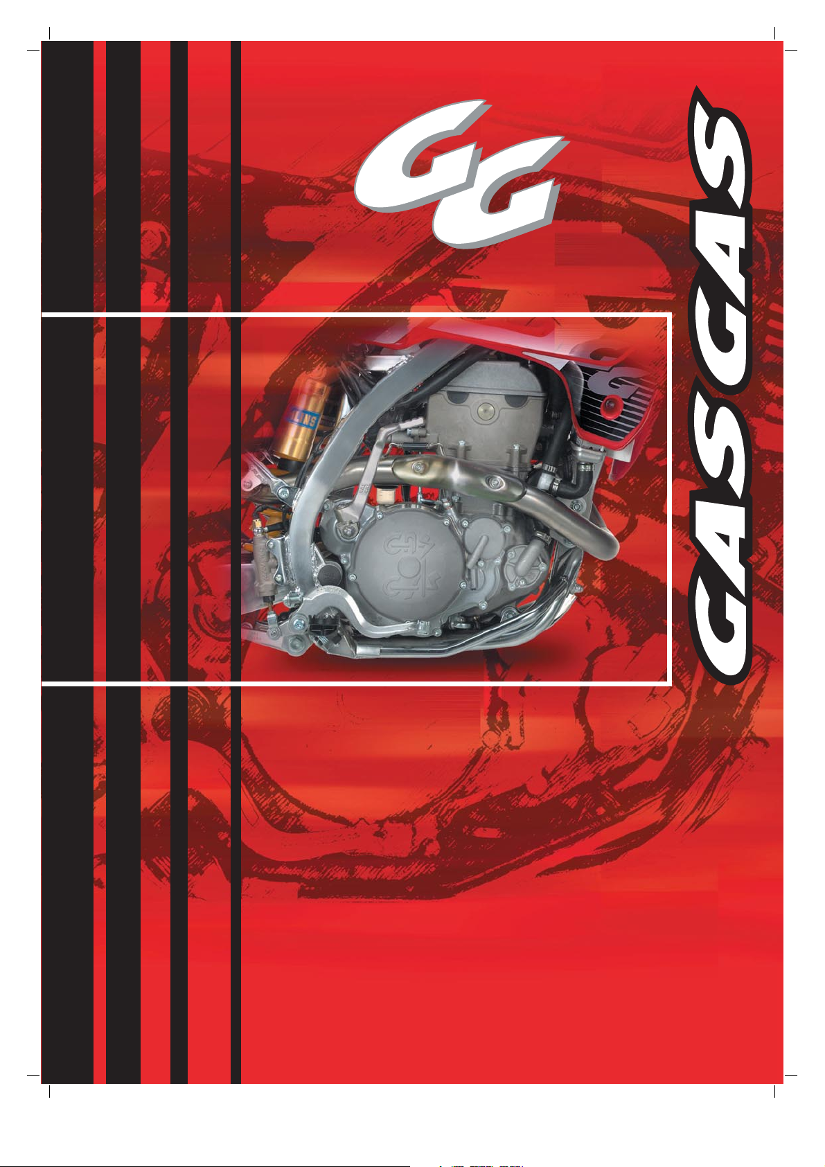
Remove the saddle and the frame covers.
Drain the oil in the engine. .
Remove the engine plate.
B
A
Drain the frame oil reservoir (A).
Drain the engine coolant (B).
Detach the cable (-) from the battery (1) and the
ground coupler from the engine (2).
2
1
88
Engine Removal and Installation
A
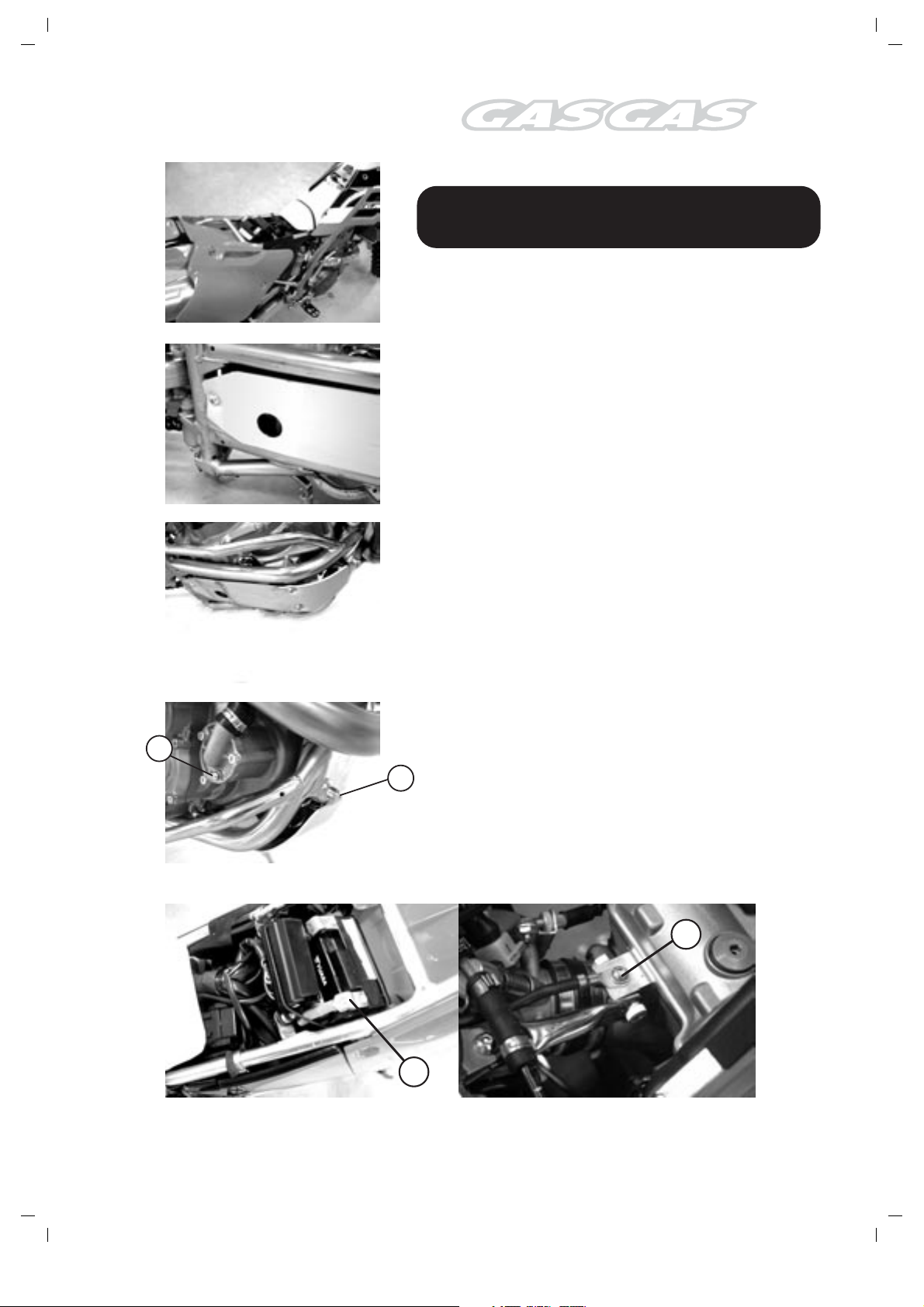
Detach the wire clamp from the alternator (A) and
the sensor cable from the tonewheel.
3
2
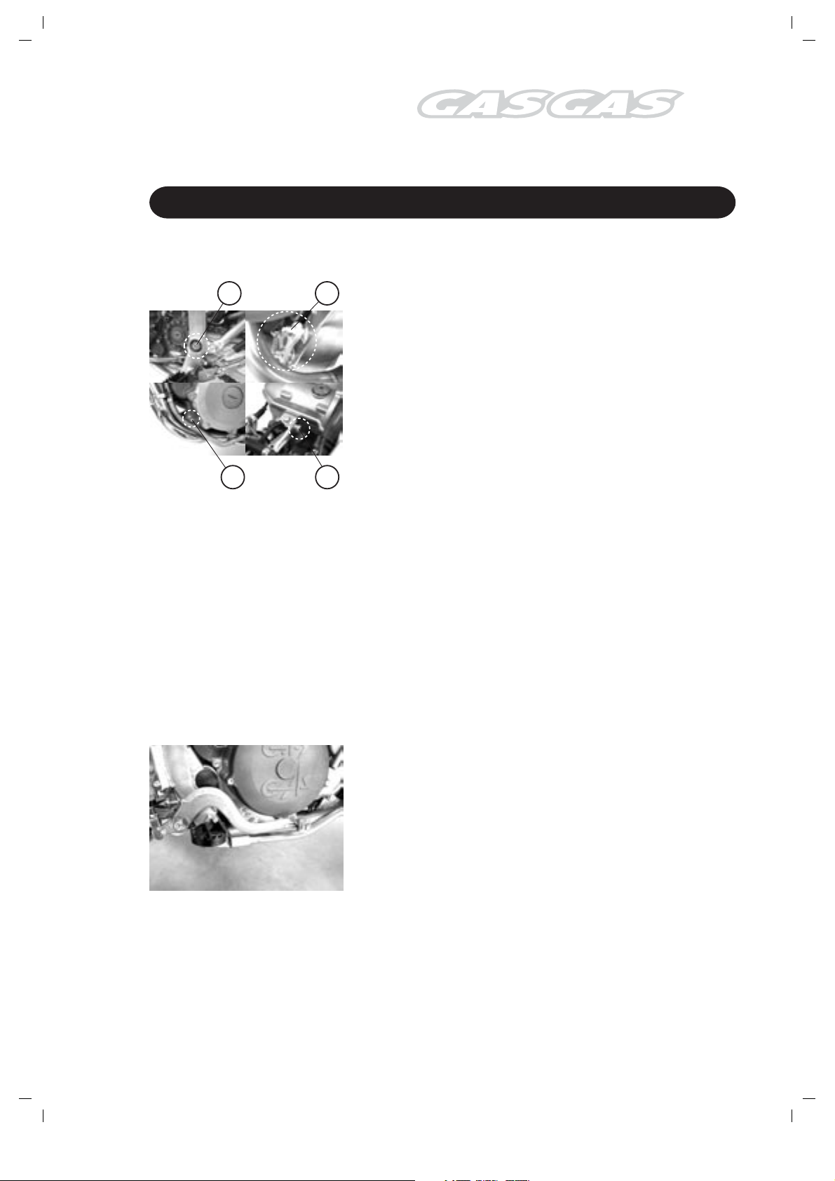
Detach the spark-plug arm (1), the engine-oil
1
devaporizing tube (2), the engine-oil reservoir
breather pipe (3).
Loosen the clamp holding the cylinder head injector
conduit (4).
4
5
Detach the wire clamp from the water-temperature
sensor (5).
Detach the connecting cable from the starter (6)
and remove the starter.
6
89
Engine Removal and Installation
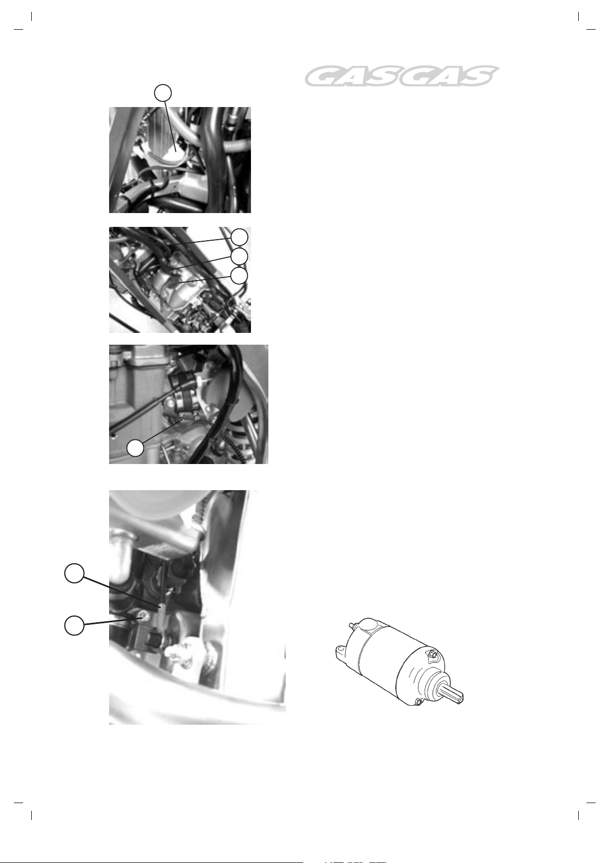
Remove the water tubes (1).
1
Remove the lever from the pedal-operated starter.
Remove the exhaust manifold (2).
2
Detach the radiator tubes.
90
Engine Removal and Installation

Detach the engine-oil tube (1) in the frame
reservoir.
1
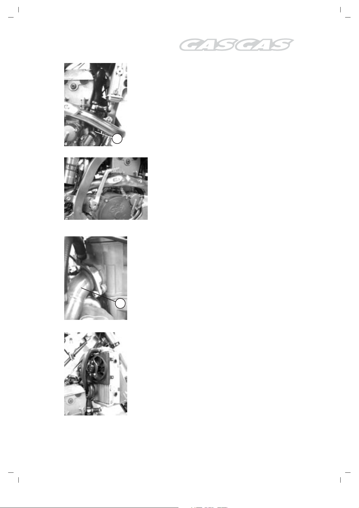
Remove the gearbox lever.
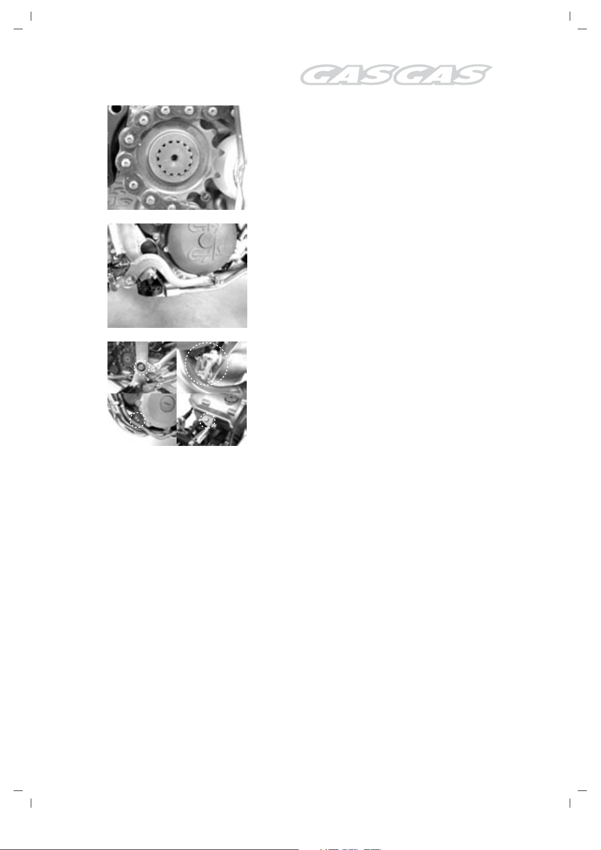
Remove the engine-pinion cover.
Remove the clutch pump.
Loosen the chain.
1
Remove the outlet pinion Seeger (1).
91
Engine Removal and Installation
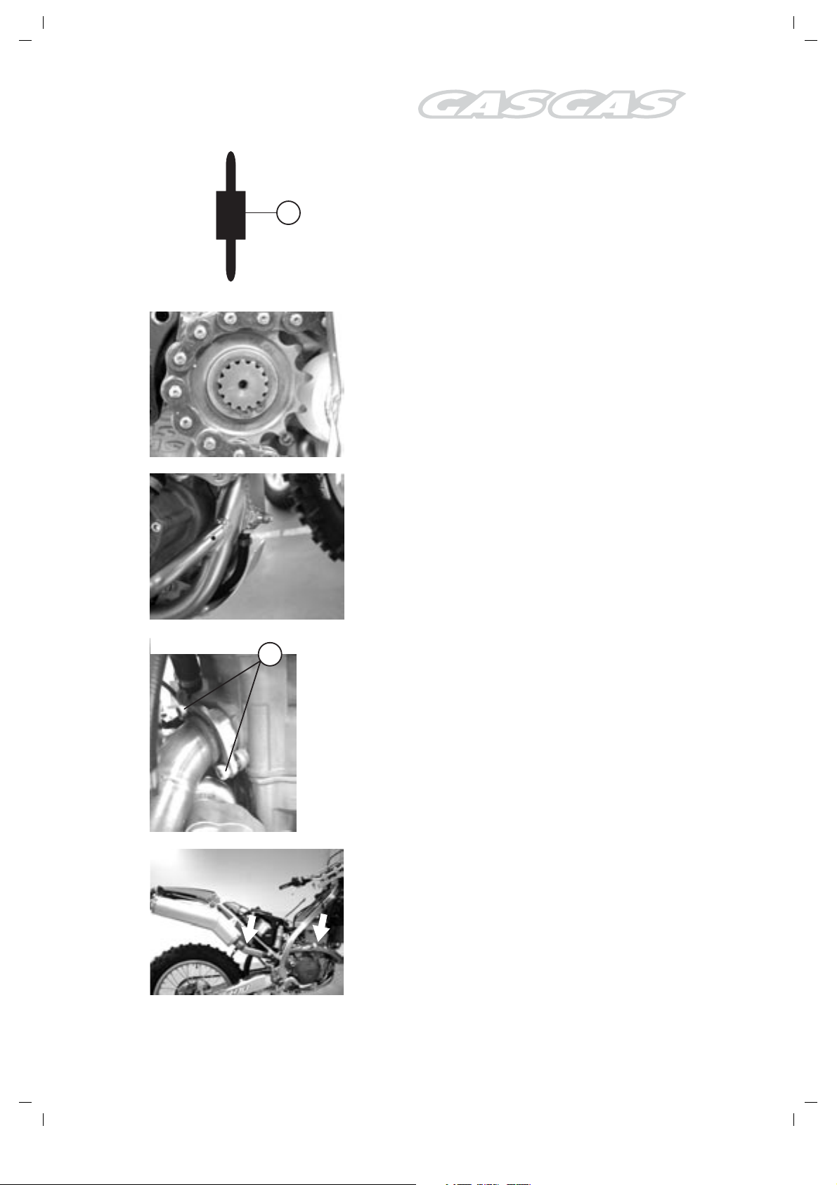
Remove the engine pinion.
Remove the split pin and the brake pedal.
CAUTION!
Replace the split pins with new ones.
Remove the engine from the frame.
!
92
Engine Removal and Installation
Engine Installation
Reverse the above operations to install the engine
AB
Fit the screws and nuts securing the engine.
NOTE:
At this stage, nuts must only be tightened
provisionally.
The nuts securing the engine are self-locking.
Upon removal, they cease to be self-locking and
become useless.
CAUTION!
Replace the nuts securing the engine with new
ones.
CD
Secure the screwheads with a spanner and tighten
the nuts securing the engine at the specified
torque.
Item Nm Kgf-m
A 66 6,6
B 66 6,6
C 14 1,4
D 66 6,6
.
!
!
!
Screw length
(A): 108 mm.
(B): 110 mm.
(D): 103 mm.
Tighten the brake-pedal screw at the specified
torque.
Brake-pedal screw: 29 Nm (2,9 Kgf-m)
93
Engine Installation
Attach the engine pinion.
A
NOTE:
The previous CW/ACW direction of this pinion
must be duly noted, so that the same wear
CW/ACW direction may be preserved.
Attach the engine pinion Seeger.
Attach the tube to the frame reservoir.
1
Tighten the exhaust manifold screw (1) at the
specified torque.
Apply NURAL 29 component to the exhaustsystem joints.
94
Engine Installation
1
3 min.
Apply LOCTITE 243 to the screw on the pedaloperated starter lever, then tighten.
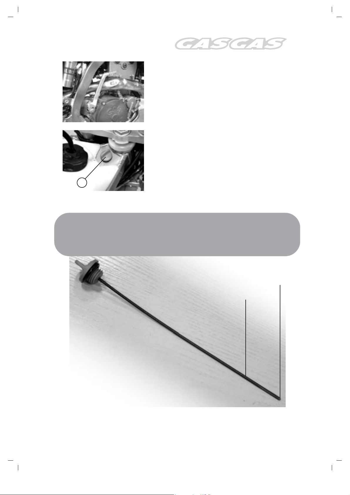
For 1.9 litre of API-compliant SF- or SG-grade
motor oil and SAE 10W-40-viscosity oil into the
oil inlet located in the frame (1) and check the
level.
DETAILS
Engine oil capacity
Oil replacement: 1.7 l
Oil and filter replacement: 1.9 l
Overall engine check: 1.9 l
Start the engine and leave it ticking over for
about 3 minutes.
Stop the engine, wait for 3 minutes, then check
the oil level with the dipstick.
!
Maximum level
95
Engine Installation
Minimum level

Engine Disassembly
96
Engine Disassembly
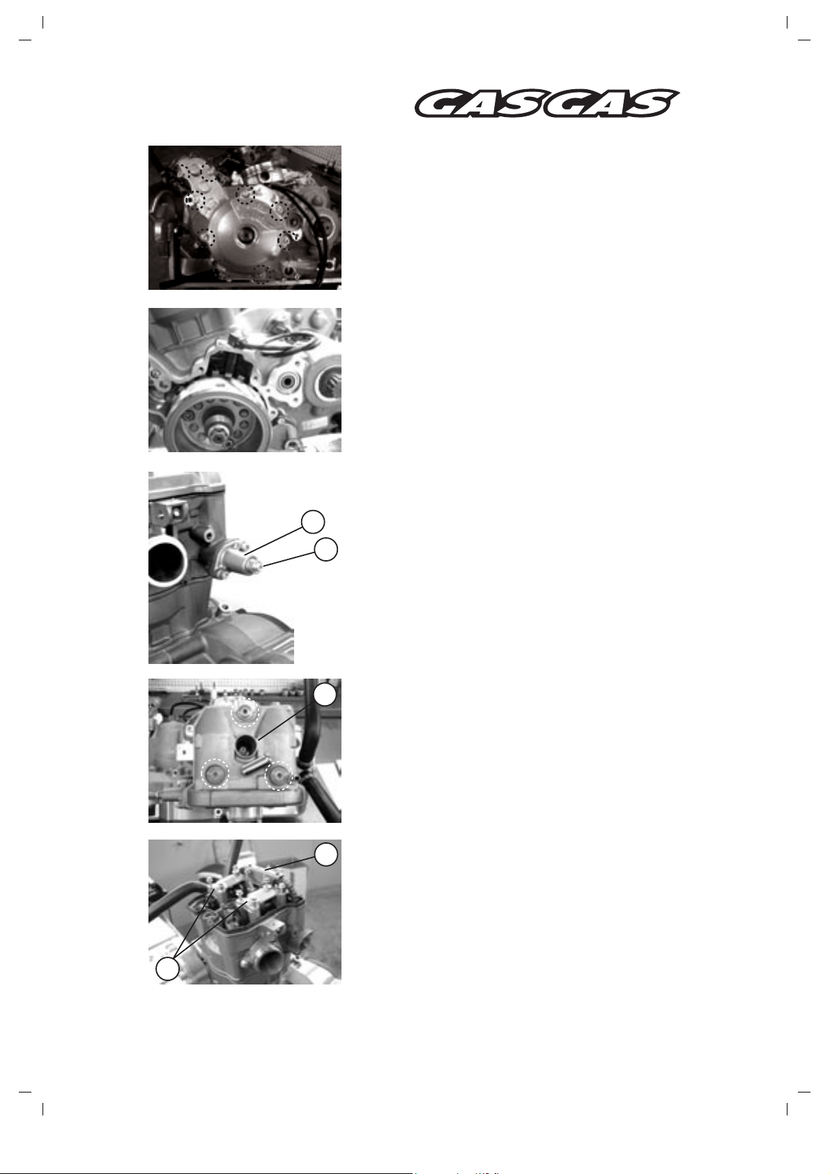
Detach the alternator cover.
Turn the alternator rotor until the 7th tonewheel
tooth becomes aligned with the position-sensor
hole centre.
NOTE:
The cylinder-head lid must be removed with
the piston in the compression stroke PMS.
!
2
1
Remove the cap bolt (1) and the timing-chain idler
(2).
5
Remove the spark plug (5).
Then, remove the cylinder-head lid screws in a
diagonal sequence and detach the cylinder-head
cover.
6
Remove the chain guide (6) and the brackets of
the camshaft journals (7).
7
98
Engine Disassembly
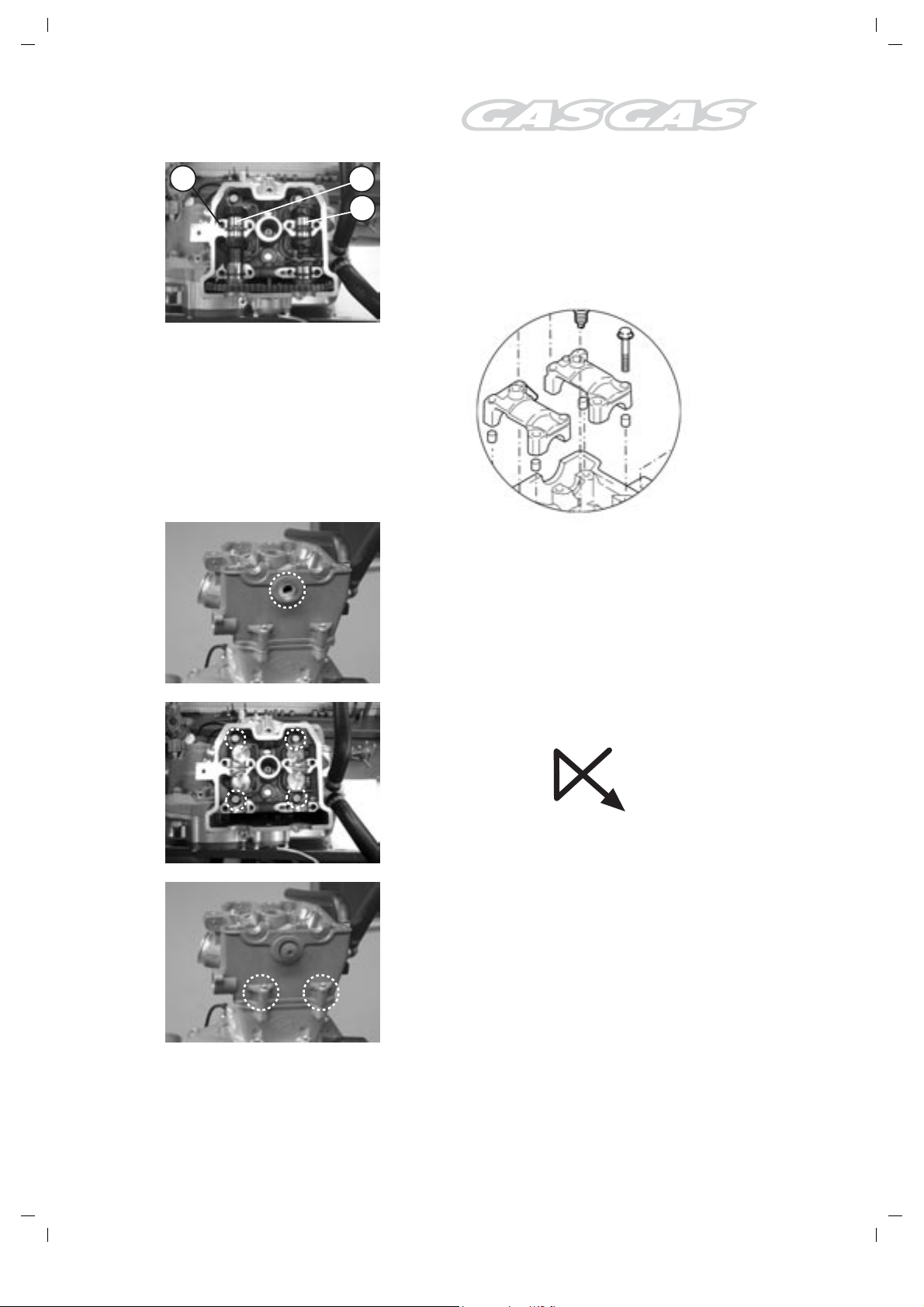
1
2
3
Remove the centering devices (1),
the input camshaft (2)
and the output camshaft (3).
NOTE:
Prevent the centering devices from falling into the
crankcase.
Remove the cylinder-head side screw.
!
Remove all four cylinder-head screws in a diagonal
sequence.
NOTE:
Prior to loosening the cylinder-head screws,
loosen the cylinder-head screws (6 mm) and
the cylinder-base screws.
Remove the cylinder-head screws and then the
cylinder head.
NOTE:
In case of difficulty removing the cylinderhead, tap it with a plastic mallet.
99
Engine Disassembly
!
!
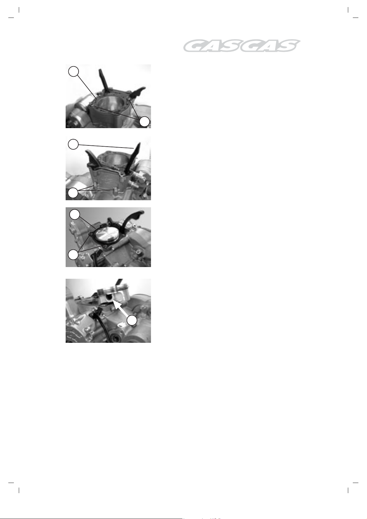
1
Remove the cylinder-head gasket (1) and the
centering devices (2).
2
3
Remove the timing-chain guide (3).
Remove the cylinder-base screws (4) and then
the cylinder.
NOTE:
4
In case of difficulty removing the cylinder, tap
it with a plastic mallet.
!
5
Remove the cylinder gasket (5) and the centering
devices (6).
6
Cover the cylinder base with a clean cloth to
prevent the piston-bolt spring ring from falling into
the crankcase.
Remove the piston-bolt spring ring. (7)
7
Remove the piston-bolt and the piston.
100
Engine Disassembly
1
2
5
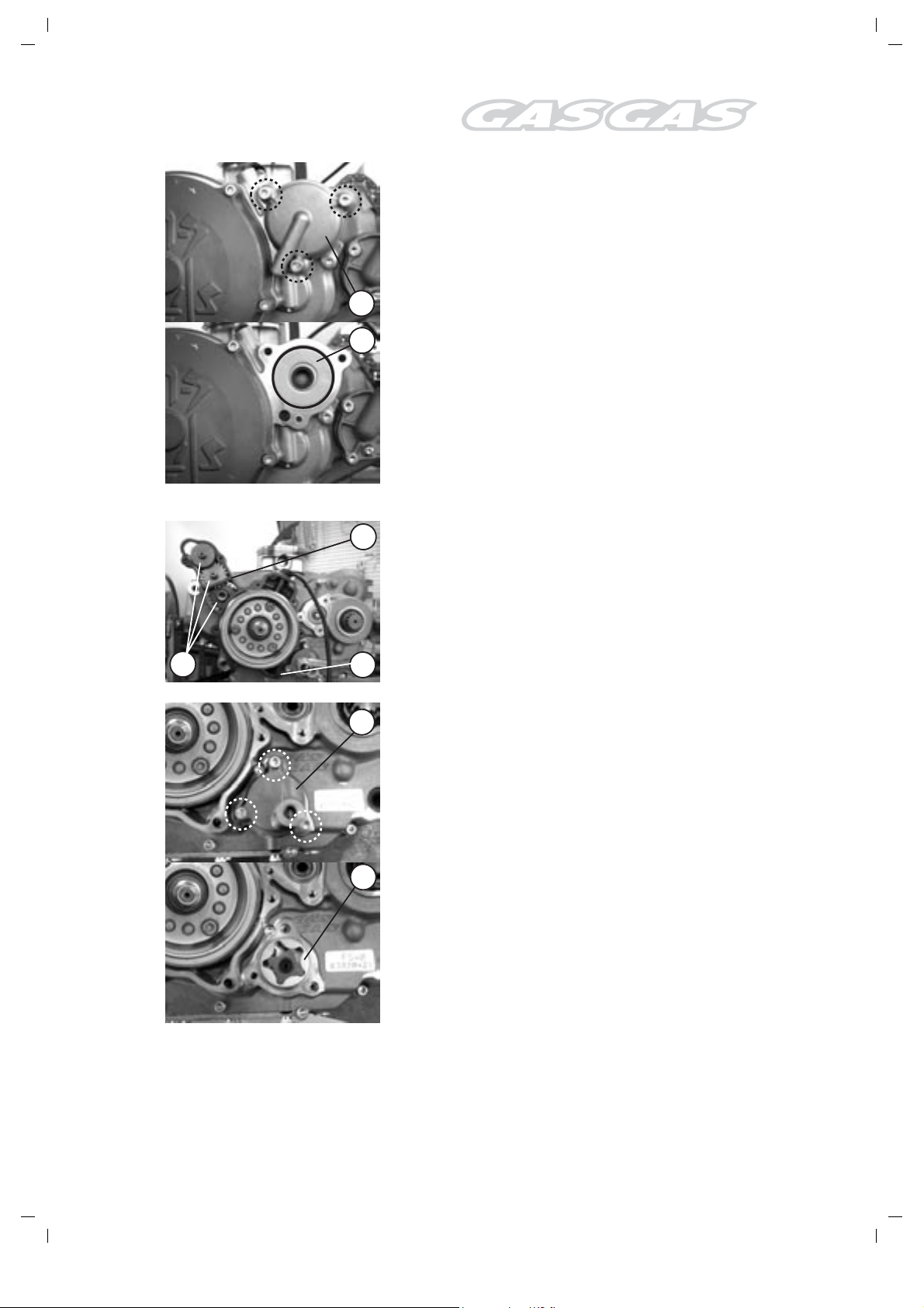
Detach the oil-filter lid (1)
and the oil filter (2).
Remove the starter followers (3), the centering
devices (4) and the gasket (5).
3
4
1
Remove the pressure-pump lid (1)
and the rotor (2).
2
101
Engine Disassembly
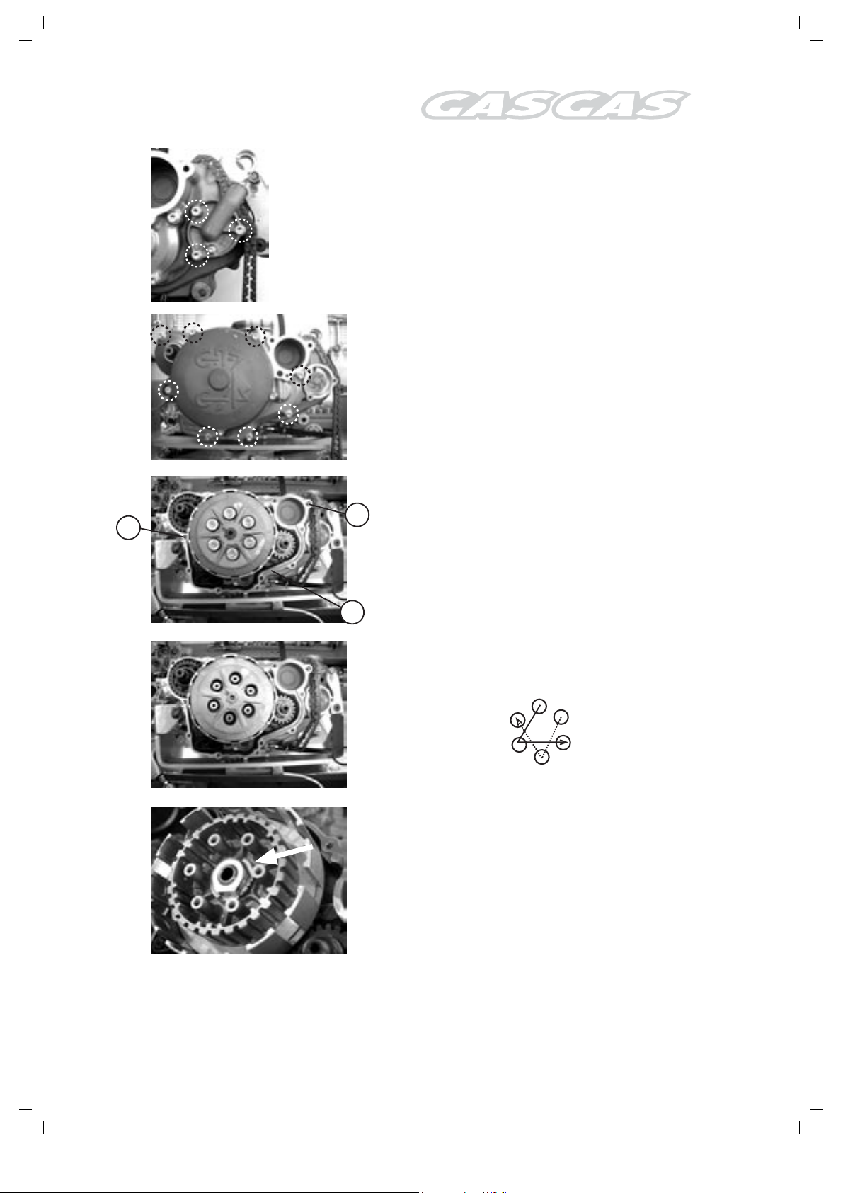
Remove the coolant-pump cover.
Remove the clutch lid.
3
3
Remove the centering devices (3)
and the gasket (4).
4
Loosen the clutch-spring screws in a diagonal
sequence (as illustrated) and remove them when
they become totally loose.
Detach the clutch press and the disc assembly.
Remove the clutch rod.
Flatten the clutch-hub washer.
102
Engine Disassembly
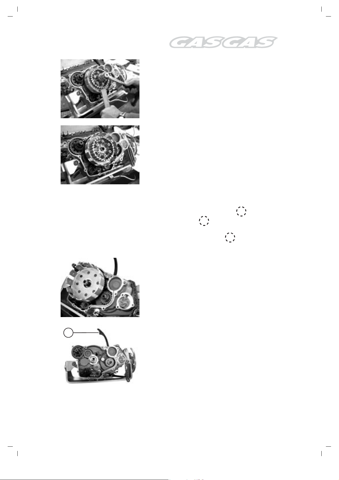
Holding the clutch hub with the special tool
supplied, remove the clutch-hub nut.
Tool Part No.:
Clutch-hub fastener
Remove the clutch hub and the washer.
CAUTION!
The clutch hub has a specific fitting position
in respect of the input shaft. Mark the position
with an indelible marker on the lubrication
groove. This mark must be taken into account
during the installation process.
!
!
Remove the clutch-drum assembly.
1
Detach the timing-chain guide idler (1).
103
Engine Disassembly
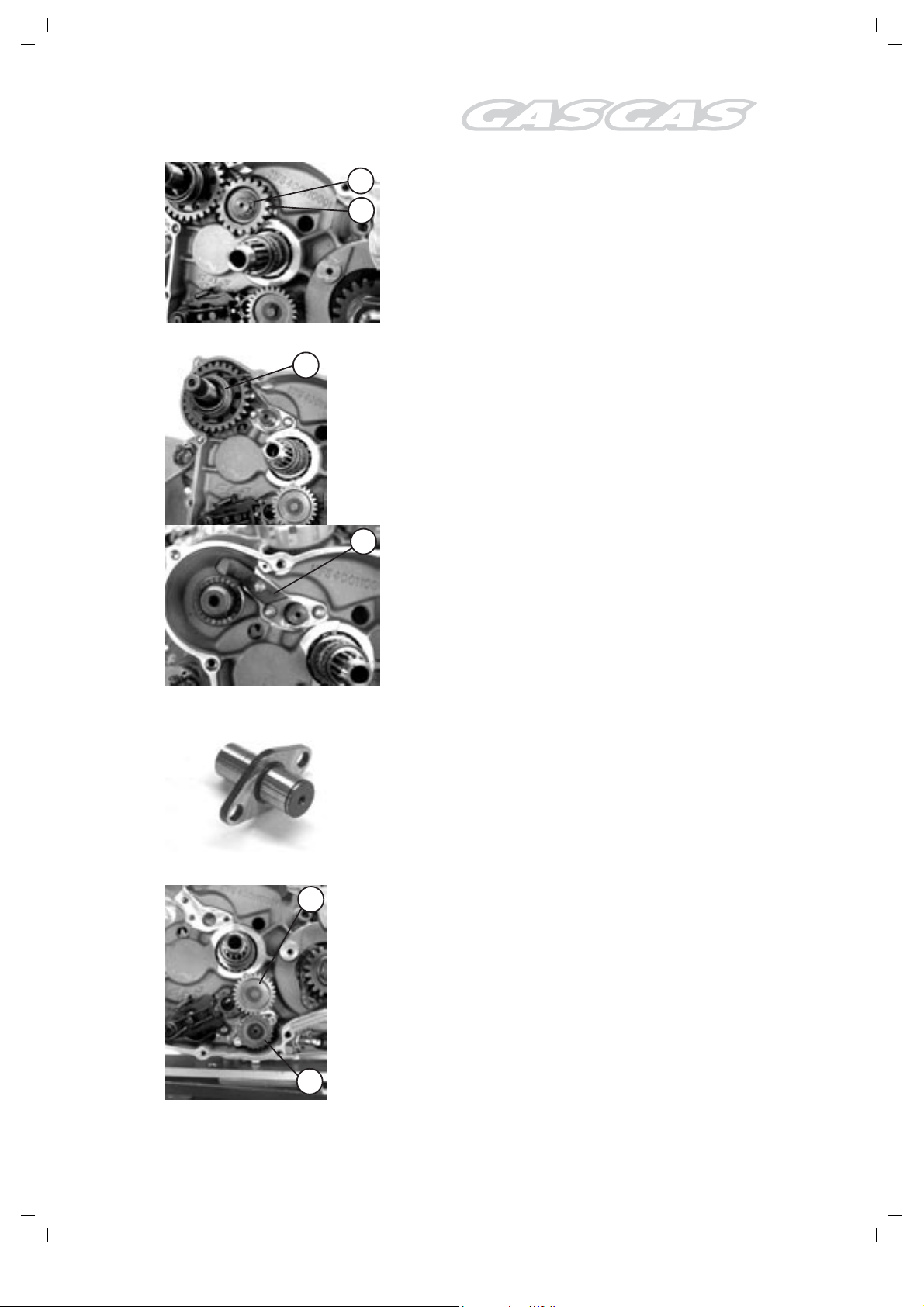
3
4
Remove the Seeger ring (3) and the
pedal-operated starter intermediate gear (4).
5
Detach the foot-operated starter assembly.
6
Detach the pedal-operated starting pawl plate (6).
Detach the pedal-operated starter intermediate
pinion shaft.
1
Detach the oil-pump intermediate gear (1)
and the oil-pump follower (2).
2
104
Engine Disassembly
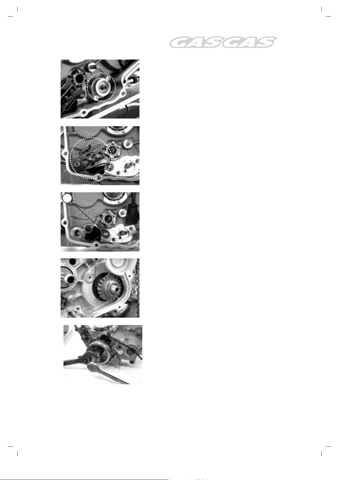
Remove the oil-pump assembly.
Remove the selector-shaft assembly.
3
Detach the gear-centering device plate (3)
Remove the crankshaft pinion bolt, the washer,
the gear, the timing chain and the timing-chain
gear.
CAUTION!
The crankshaft pinion bolt has a left-hand
thread.
Remove the alternator-rotor bolt and washer.
Holding the puller with a spanner, loosen the rotor.
Tool Part No.:
MFS400134045, FSE400 flywheel puller
105
Engine Disassembly
!
!
Use the special tool supplied to detach the
alternator rotor.
CAUTION!
Tapping the alternator rotor with a hammer
might damage it.
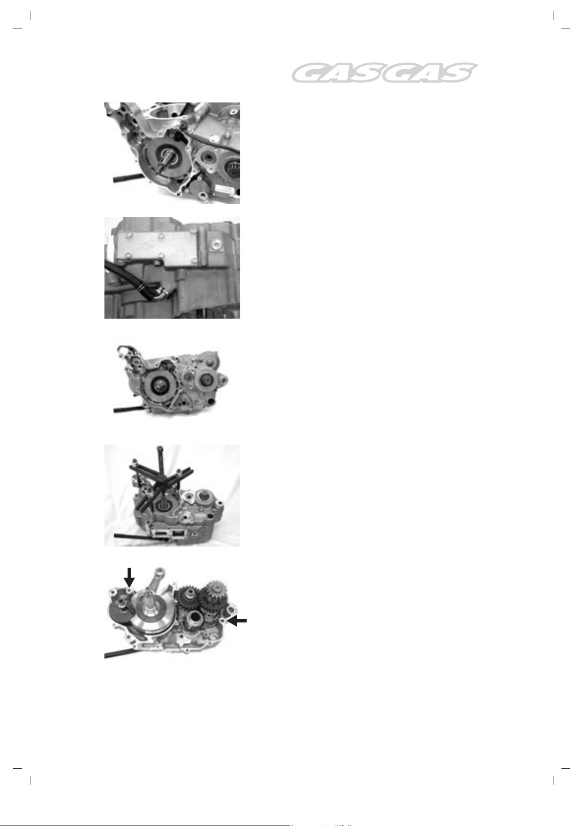
Remove the lower oil-reservoir lid.
Remove the crankcase left-hand set screws.
!
Detach the crankcase using the special tool
supplied.
Tool Part No.:
ME2595000: crankcase-detachment tool
NOTE:
Fit the crankcase-detachment tool on the lefthand side, so that its plate becomes parallel
with the surface of the crankcase end.
Remove the centering devices.
106
Engine Disassembly
!
!

1
1
Remove the shafts of the shifter forks (1) and the
2
2
forks (2).
3
5
6
4
Detach the gearbox input-shaft assembly (3) and
the gearbox output-shaft assembly (4).
Detach the crankshaft (5) and the rocker shaft
(6).
NOTE:
Should this detachment operation prove
difficult, tap both shafts with a plastic mallet
in an alternating pattern.
Remove the oil-intake filter and clean it.
!
107
Engine Disassembly
 Loading...