

GMA 1347D
Installation Manual
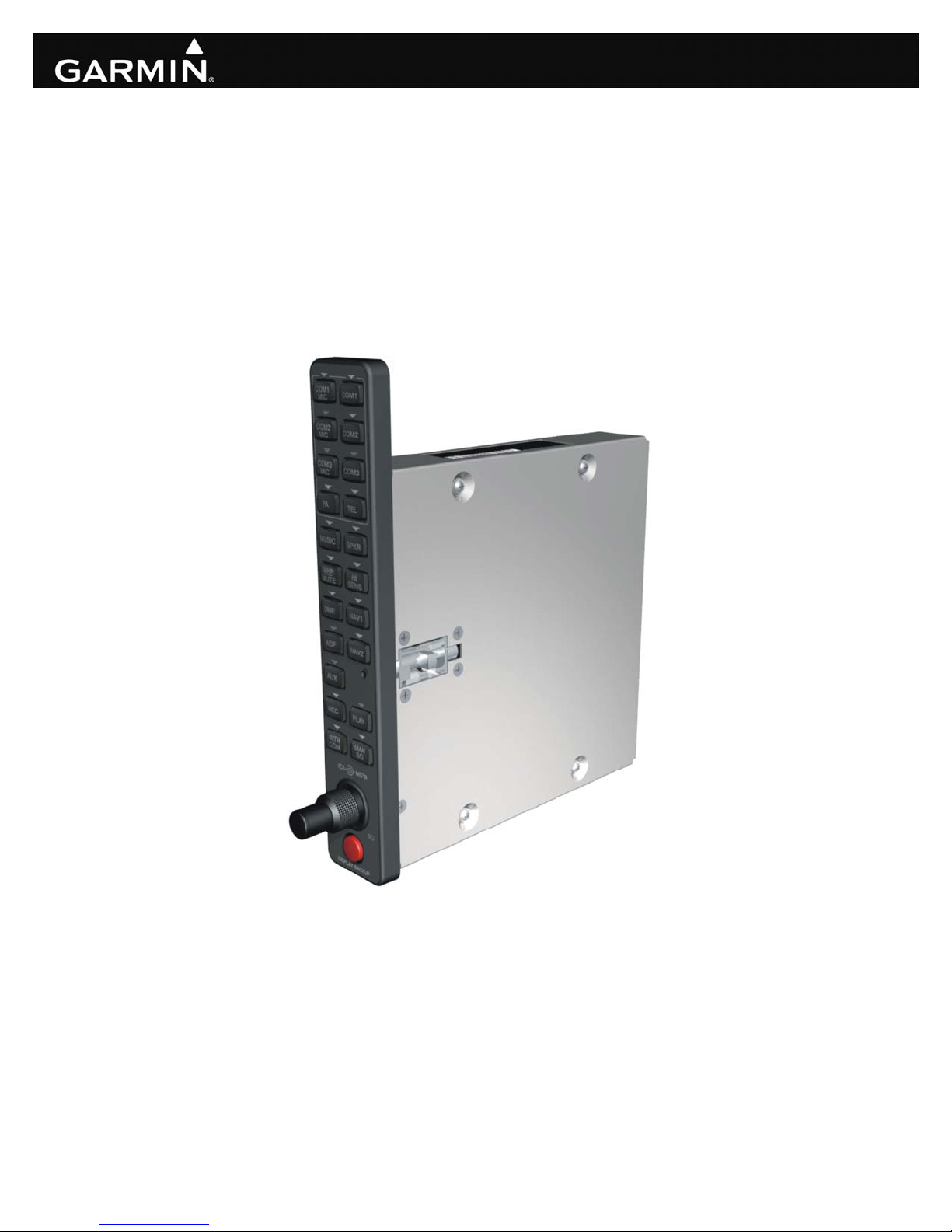
(GMA 1347D -00 Shown)
190-00303-21 January, 2010 Revision C

© Copyright 2005 - 2010
Garmin Ltd. or its subsidiaries
All Rights Reserved
Except as expressly provided herein, no part of this manual may be reproduced, copied, transmitted,
disseminated, downloaded or stored in any storage medium, for any purpose without the express prior
written consent of Garmin. Garmin hereby grants permission to download a single copy of this manual
and of any revision to this manual onto a hard drive or other electronic storage medium to be viewed and
to print one copy of this manual or of any revision hereto, provided that such electronic or printed copy of
this manual or revision must contain the complete text of this copyright notice and provided further that
any unauthorized commercial distribution of this manual or any revision hereto is strictly prohibited.
Garmin International, Inc.
1200 E. 151
st
Street
Olathe, KS 66062 USA
Telephone: 913-397-8200
Aviation Dealer Technical Support Line (Toll Free): (888) 606-5482
www.garmin.com
Garmin (Europe) Ltd
Liberty House
Bulls Copse Road
Hounsdown Business Park
Southampton, SO40 9RB, UK
Telephone: 44 (0) 8708501241
RECORD OF REVISIONS
Revision
A 5/9/06 Production Release
B 8/14/07 Added the -20 unit
C 1/14/10
Revision
Date
Description
Added marker beacon antenna cable termination guidance
Page A GMA 1347D Installation Manual
Revision C 190-00303-21
Revision
C
CURRENT REVISION DESCRIPTION
Page
Number(s)
1-1 1.2
1-2 1.2.2 Added to Interface Summary
1-7 1.6 Updated warranty statement
2-1
2-2 – 2-3 2.3.1
Section
Number
2.1
&
2.2.2
Description of Change
Added “DME, ADF, MKR, TEL, AUX” to Equipment
Description
Updated AC reference
Added marker beacon installation guidance
DOCUMENT PAGINATION
Section Page Range
Table of Contents i - vi
Section 1 1-1 – 1-8
Section 2 2-1 – 2-6
Section 3 3-1 – 3-4
Section 4 4-1 – 4-12
Appendix A A-1 – A-6
Appendix B B-1 – B-12
GMA 1347D Installation Manual Page i
190-00303-21 Revision C

This manual reflects the operation of software version 4.00. Some differences in operation may be
observed when comparing the information in this manual to earlier or later software versions.
INFORMATION SUBJECT TO EXPORT CONTROL LAWS
This document may contain information which is subject to the Export Administration Regulations
("EAR") issued by the United States Department of Commerce (15 CFR, Chapter VII, Subchapter C) and
which may not be exported, released, or disclosed to foreign nationals inside or outside of the United
States without first obtaining an export license. A violation of the EAR may be subject to a penalty of up
to 10 years imprisonment and a fine of up to US $1,000,000 under Section 2410 of the Export
Administration Act of 1979. Include this notice with any reproduced portion of this document.
WARNING
This product, its packaging, and its components contain chemicals known to the state of
California to cause cancer, birth defects, or reproductive harm. This notice is being
provided in accordance with California’s proposition 65. If you have any questions or
would like additional information, please refer to our web site at
www.garmin.com/prop65
.
Page ii GMA 1347D Installation Manual
Revision C 190-00303-21

TABLE OF CONTENTS
PARAGRAPH PAGE
1 GENERAL DESCRIPTION..............................................................................................................1-1
1.1 Introduction........................................................................................................................................1-1
1.2 Equipment Description......................................................................................................................1-1
1.3 Technical Specifications ...................................................................................................................1-3
1.4 Certification.......................................................................................................................................1-5
1.5 Reference Documents .......................................................................................................................1-6
1.6 Limited Warranty...............................................................................................................................1-7
2 INSTALLATION OVERVIEW........................................................................................................2-1
2.1 Introduction........................................................................................................................................2-1
2.2 Installation Materials .........................................................................................................................2-1
2.3 Installation Considerations ................................................................................................................2-2
2.4 Cabling & Wiring ..............................................................................................................................2-4
2.5 Cooling Air........................................................................................................................................2-4
2.6 Mounting Requirements ....................................................................................................................2-5
2.7 Installation Approval Considerations for Pressurized Aircraft .........................................................2-6
2.8 Electrical Noise..................................................................................................................................2-6
3 INSTALLATION PROCEDURE......................................................................................................3-1
3.1 Unpacking Unit..................................................................................................................................3-1
3.2 Antenna Installation...........................................................................................................................3-1
3.3 Antenna Cable Connectors ................................................................................................................3-1
3.4 Electrical Connections.......................................................................................................................3-1
3.5 Backshell Assembly...........................................................................................................................3-2
3.6 GMA 1347D Unit Installation...........................................................................................................3-3
3.7 Post Installation Configuration and Checkout...................................................................................3-3
3.8 Continued Airworthiness...................................................................................................................3-3
4 SYSTEM INTERCONNECTS..........................................................................................................4-1
4.1 Connector Description.......................................................................................................................4-1
4.2 Connectors J3471 and J3472 .............................................................................................................4-1
4.3 J3472 Connector Pin Assignments....................................................................................................4-6
4.4 J3471 Connector Pin Assignments....................................................................................................4-9
GMA 1347D Installation Manual Page iii
190-00303-21 Revision C

PARAGRAPH PAGE
APPENDIX A ASSEMBLY AND INSTALLATION DRAWINGS......................................................A-1
APPENDIX B INTERCONNECT DRAWINGS....................................................................................B-1
LIST OF ILLUSTRATIONS
FIGURE PAGE
2-1 GMA Marker Beacon Coaxial Cable D-Sub Termination.................................................................2-3
2-2 GMA 1347D Unit Rack.....................................................................................................................2-5
4-1 Rear Connectors, J3471 and J3472 Viewed From Back of Unit.......................................................4-1
A-1 GMA 1347D Outline Drawing.........................................................................................................A-1
A-2 GMA 1347D Connector/Rack Assembly Drawing ..........................................................................A-3
A-3 GMA 1347D Recommended Panel Cutout Dimensions...................................................................A-5
B-1 GMA 1347D Power, Antenna and Reversionary Mode Interconnect Wiring Diagram...................B-1
B-2 GMA 1347D Power, Antenna and Reversionary Mode Interconnect Wiring Diagram...................B-3
B-3 Mic and Phone Jack Connections, Interconnect Wiring Diagram....................................................B-5
B-4 Transceiver Analog Connections, Interconnect Wiring Diagram..................................................... B-7
B-5 Transceiver Digital Connections, Interconnect Wiring Diagram ..................................................... B-9
B-6 Discrete Lines, Interconnect Wiring Diagram ................................................................................B-11
Page iv GMA 1347D Installation Manual
Revision C 190-00303-21

LIST OF TABLES
TABLE PAGE
2-1 Pin and Crimp Tool Part Numbers.....................................................................................................2-3
3-1 Pin Contact Part Numbers..................................................................................................................3-1
3-2 Recommended Crimp Tools..............................................................................................................3-2
4-1 J3471 Pin Assignments......................................................................................................................4-2
4-2 J3472 Pin Assignments......................................................................................................................4-4
4-3 Aircraft Power Pin Assignments, J3472............................................................................................4-6
4-4 Aircraft Lighting Pin Assignments, J3472.........................................................................................4-6
4-5 RS-232 Pin Assignments, J3472........................................................................................................4-6
4-6 Marker Beacon Pin Assignments, J3472........................................................................................... 4-7
4-7 Reversionary Mode Pin Assignments, J3472 ....................................................................................4-8
4-8 Speaker Pin Assignments, J3472.......................................................................................................4-8
4-9 Digital Audio Pin Assignments, J3472..............................................................................................4-8
4-10 PA MUTE Pin Assignments, J3472 ..................................................................................................4-8
4-11 Mic Audio Inputs and Mic Key Pin Assignments, J3471..................................................................4-9
4-12 Remote ICS Audio and ICS Keys Pin Assignments, J3471..............................................................4-9
4-13 Com Audio and Mic Keys Pin Assignments, J3471........................................................................4-10
4-14 Nav Audio Pin Assignments, J3471................................................................................................4-10
4-15 Headset Outputs Pin Assignments, J3471.......................................................................................4-11
4-16 Music Inputs Pin Assignments, J3471.............................................................................................4-11
4-17 Unswitched Audio Inputs Pin Assignments, J3471.........................................................................4-11
4-18 Telephone Inputs/Outputs Pin Assignments, J3471 ........................................................................4-11
4-19 AUX, DME and ADF Audio Pin Assignments, J3471....................................................................4-12
4-20 Failsafe Audio Pin Assignments, J3471..........................................................................................4-12
4-21 Summed Audio Pin Assignments, J3471.........................................................................................4-12
GMA 1347D Installation Manual Page v
190-00303-21 Revision C
GMA 1347D HARDWARE MOD LEVEL HISTORY
The following table identifies hardware modification (Mod) Levels for the GMA 1347D Audio Panel.
Mod Levels are listed with the associated service bulletin number, service bulletin date, and the purpose
of the modification. The table is current at the time of publication of this manual (see date on front cover)
and is subject to change without notice. Authorized Garmin Sales and Service Centers are encouraged to
access the most up-to-date bulletin and advisory information on the Garmin Dealer Resource web site at
www.garmin.com using their Garmin-provided user name and password.
MOD
LEVEL
SERVICE
BULLETIN
NUMBER
SERVICE
BULLETIN
DATE
PURPOSE OF MODIFICATION
Page vi GMA 1347D Installation Manual
Revision C 190-00303-21

1 GENERAL DESCRIPTION
1.1 Introduction
This manual presents mechanical and electrical installation requirements for installing the Garmin
GMA 1347D audio panel, as part of the Garmin Integrated Flight Deck. The GMA 1347D can be
incorporated into a variety of airframes under appropriate TC or STC. Each airframe installation may
vary. Use only approved (type or supplemental type) data for specific installation instructions in a
particular aircraft.
1.2 Equipment Description
The Garmin GMA 1347D is a vertically oriented panel mounted audio control and marker beacon system.
The system delivers reliability and versatility for all audio controlling functions. LED-illuminated push
buttons and logical panel layout allow audio selection of NAV, COM, DME, ADF, MKR, TEL, AUX,
and automatic warning audio in voice or tone annunciation. LED brightness is adjusted to a level
appropriate for ambient cockpit light conditions automatically by the GDU or manually with radio
lighting controls, depending upon installation connections. A failsafe circuit connects the pilot’s headset
and microphone directly to ON-SIDE COM in case power is interrupted or the unit is turned off.
The Garmin GMA 1347D Audio Panel incorporates a microcontroller for processing front panel key
commands, annunciator control, input/output functions, and communication.
The GMA 1347D includes a five-position intercom system (ICS) with electronic cabin noise de-emphasis
and two stereo music inputs. A dual installation extends the number of ICS positions to ten. The
intercom provides two selectable modes of isolation (Intercom ON, Intercom OFF). A pilot-selectable
cabin speaker output can be used to listen to the selected aircraft radios. The PA function is pilot
selectable and allows communication to the passengers.
The GMA 1347D provides configurable passenger volume and pilot adjustable master and ICS volume.
The GMA 1347D provides digital audio input/output capability to external radios. The unit is capable of
digitally interfacing with two transceivers and two receivers. For every channel except COM 3, the unit
generates both digital and analog outputs, and combines both digital and analog inputs.
The GMA 1347D provides a digital recorder with playback capability. Recording is selectable via the
REC button. Playback is controlled by pressing the PLAY button. The digital clearance recorder can
playback up to two and a half minutes of recording.
The marker beacon receiver with dual sensitivity and audio muting with automatic re-arming is included
in the unit.
The GMA 1347D (-20) includes a “CABIN” button, enabling cabin to cockpit communications.
GMA 1347D Installation Manual Page 1-1
190-00303-21 Revision C

1.2.1 Features Summary
• Logical front panel layout
• LED annunciators indicate selected function
• Five position intercom: pilot and four passengers
• Two stereo headset amplifiers: one for the pilot and one for the passengers
• Two stereo music source inputs
• Two selectable intercom operational modes
• VOX control for mic inputs
• Automatic selection of radio audio source when corresponding mic is selected
• MASQ
TM
Processing
• COM swap function
• TX indication
• SmartMute
TM
marker audio muting
• Speaker output for radios
• Power-off fail safe connection for Pilot PTT, mic and Pilot’s Headset-Left to ON-SIDE COM
• Digital audio interface
• Voice Recorder
• Cockpit Call (-20 only)
1.2.2 Interface Summary
The following is an interface summary for the GMA 1347D. See Section 4 and Appendix B for
connection details.
• 3 Transceiver Inputs/Outputs (Figure B-4)
• 1 Speaker Output (Figures B-1 and B-2)
• 2 Headset Outputs (Figure B-3)
• 5 Microphone Inputs (Figure B-3)
• 5 Receiver Inputs (Figure B-4)
• 4 Unswitched Inputs (Figure B-4)
• 6 Digital Audio Inputs (Figure B-5)
• 2 Aircraft Power Inputs (Figures B-1 and B-2)
• Discrete Inputs/Outputs (Figure B-6)
• PFD/MFD Reversionary Mode outputs (Figures B-1 and B-2)
• 2 RS-232 Inputs/Outputs (Figure B-5)
• Marker Beacon Antenna Input (Figures B-1 and B-2)
• External Marker Beacon Lamp Driver Outputs (Figure B-6)
Page 1-2 GMA 1347D Installation Manual
Revision C 190-00303-21

1.3 Technical Specifications
It is the responsibility of the installing agency to obtain the latest revision of the GMA 1347D
Environmental Qualification Form. This form is available directly from Garmin under the following part
number:
GMA 1347D Environmental Qualification Form, Garmin part number 005-00314-79
To obtain a copy of this form, see the dealer/OEM portion of the Garmin web site (www.garmin.com)
.
1.3.1 Physical Characteristics
Characteristic Specification
Bezel Height 7.70 inches (196 mm)
Bezel Width 1.30 inches (33 mm)
Rack Height 6.30 inches (160 mm)
Rack Width 1.325 inches (34 mm)
Depth Behind Panel with
Connectors (measured from face
of aircraft panel to rear of
connector backshells)
7.79 inches (198 mm)
GMA 1347D Unit Weight 1.7 lbs. (0.8 kg)
GMA 1347D Rack Weight
(Installed with rack and
2.4 lbs. (1.1 kg)
connectors)
GMA 1347D Installation Manual Page 1-3
190-00303-21 Revision C
1.3.2 Electrical Characteristics
Characteristic Specification
Regulatory Compliance RTCA/DO-160D Environmental Conditions and EUROCAE/ED-14D
Unit Software RTCA/DO-178B Level C
CLD (Custom Logic
Devices) Compliance
Temperature Range
Power Requirements
Altitude 55,000 Feet
Audio Panel
Intercom
Headphone Outputs
Speaker Outputs
Marker Beacon Receiver
RTCA/DO-254 Level C
-45°C to +70°C
Supply Voltage: 28 VDC
See the Environmental Qualification Form for details on surge ratings and
minimum/maximum operating voltages.
Operating Current: 1.75 amps max at 27.5 V
Transceiver inputs: 3
Receiver inputs: 5
Unswitched inputs: 4
Input impedance: 500 Ω
Input isolation: 60 dB minimum
Special functions: Failsafe operation
MASQ
TM
processing
Positions: 5 (pilot and 4 passengers per GMA 1347D)
Volume controls: 2 (pilot, passengers)
VOX level controls: 2 (pilot, passengers)
VOX circuits: 5 (one per mic input)
Music inputs (stereo): 2
Music input impedance: 5 kΩ
Music input level: Less than 500 mVac RMS for full output (typical).
1 Vac RMS MAX (3 Vp-p)
Microphone signal processing: 9 pole characteristic and special cabin
noise band de-emphasis
Intercom isolation modes (-00): 2 (Pilot Isolate, Crew Isolate)
Intercom isolation modes (-20): 4 (Pilot Isolate, Crew Isolate,
Copilot Isolate, All ICS Mode)
Special functions: Recorder with playback (selectable recording of
selected COMs) up to 2.5 minutes of recording time.
Automatic squelch: 5 (one per mic input) pilot selectable between auto
and manual.
Output amplifiers: 2, stereo (pilot, passengers)
Fidelity: Power into 150
Ω Distortion
50 mW <0.5%
100 mW <5%
Frequency response: Music: 50 Hz to 20 kHz nominal
Aircraft radio: 200 Hz to 6 kHz nominal
ICS mic: (Special cabin noise band de-emphasis)
Outputs selectable: 1, pilot selectable
Output power: 10 watts into 4 Ω or 8 Ω, @ any normal supply voltage.
Frequency response: 350 Hz to 6 kHz nominal
Frequency: Crystal controlled at 75 MHz
Sensitivity: LO 1000 μV; HI 200 μV
Selectivity: 6 dB @ ±10 kHz min, 40 dB @ ±200 kHz max.
Input impedance: 50 Ω
External lamp drive: 125 mA max each output
Other outputs: Middle MKR sense
Special functions: SmartMute
TM
marker audio muting
Page 1-4 GMA 1347D Installation Manual
Revision C 190-00303-21
1.4 Certification
The conditions and tests required for TSO approval of this article are minimum performance standards. It
is the responsibility of those installing this article either on or within a specific type or class of aircraft to
determine that the aircraft installation conditions are within the TSO standards. TSO articles must have
separate approval for installation in an aircraft. The article may be installed only if performed under 14
CFR part 43 or the applicable airworthiness requirements.
1.4.3 TSO/ETSO Compliance
Function TSO/ETSO Category
Audio Selector
Panels And
Amplifiers
Airborne Radio
Marker Receiving
Equipment
TSO-C50c
ETSO-C50c
TSO-C35d
ETSO-2C35d
Class A
Applicable
LRU SW Part
Numbers
(011-01257-00)
All
006-B0203-()
except
006-B0203-00
through
006-B0203-29
All
006-B0203-()
except
006-B0203-00
through
006-B0203-29
Applicable
LRU SW Part
Numbers
(011-01257-20)
All
006-B0203-()
except
006-B0203-00
through
006-B0203-39
All
006-B0203-()
except
006-B0203-00
through
006-B0203-39
Applicable CLD
Part Numbers
(011-01257-00)
006-C0051-20*
006-C0075-00*
006-C0075-01*
006-C0075-03*
006-C0090-()
006-C0091-()
006-C0051-20*
006-C0075-00*
006-C0075-01*
006-C0075-03*
006-C0090-()
006-C0091-()
Applicable CLD
Part Numbers
(011-01257-20)
006-C0090-()
006-C0091-()
006-C0090-()
006-C0091-()
*Not RTCA/DO-254 Level C Compliant
1.4.4 TSO/ETSO Deviations
TSO Deviation
TSO-C35d
TSO-C50c
1. Garmin was granted a deviation from TSO-C35d to use RTCA DO-160D instead of
RTCA DO-138 as the standard for Environmental Conditions and Test Procedures for
Airborne Equipment.
2. Garmin was granted a deviation from TSO-C35d to use FAR §21.607(d) instead of FAR
§37.7 as the general rules governing holders of the TSO authorizations.
1. Garmin was granted a deviation from TSO-C50c to use RTCA DO-178B instead of
RTCA DO-178A as the standard for Software Considerations in Airborne Systems and
Equipment Certification.
2. Garmin was granted a deviation from TSO-C50c to use RTCA DO-178B instead of
RTCA DO-178A to demonstrate compliance for the verification and validation of the
computer software.
GMA 1347D Installation Manual Page 1-5
190-00303-21 Revision C

1.5 Reference Documents
The following publications are sources of additional information for installing the GMA 1347D. Before
installing the unit, the technician should read all referenced materials along with this manual.
Part Number Document
190-00303-00 G1000 System Installation Manual
190-00303-04
G1000 Line Maintenance and
Configuration Manual
Page 1-6 GMA 1347D Installation Manual
Revision C 190-00303-21

1.6 Limited Warranty
All Garmin avionics products are warranted to be free from defects in materials or workmanship for: two years from
the date of purchase for new Remote-Mount and Panel-Mount products; one year from the date of purchase for new
portable products and any purchased newly-overhauled products; six months for newly-overhauled products
exchanged through a Garmin Authorized Service Center; and 90 days for factory repaired or newly-overhauled
products exchanged at Garmin in lieu of repair. Within the applicable period, Garmin will, at its sole option, repair
or replace any components that fail in normal use. Such repairs or replacement will be made at no charge to the
customer for parts or labor, provided that the customer shall be responsible for any transportation cost. This
warranty does not apply to: (i) cosmetic damage, such as scratches, nicks and dents; (ii) consumable parts, such as
batteries, unless product damage has occurred due to a defect in materials or workmanship; (iii) damage caused by
accident, abuse, misuse, water, flood, fire, or other acts of nature or external causes; (iv) damage caused by service
performed by anyone who is not an authorized service provider of Garmin; or (v) damage to a product that has been
modified or altered without the written permission of Garmin. In addition, Garmin reserves the right to refuse
warranty claims against products or services that are obtained and/or used in contravention of the laws of any
country.
THE WARRANTIES AND REMEDIES CONTAINED HEREIN ARE EXCLUSIVE AND IN LIEU OF ALL
OTHER WARRANTIES, WHETHER EXPRESS, IMPLIED OR STATUTORY, INCLUDING ANY LIABILITY
ARISING UNDER ANY WARRANTY OF MERCHANTABILITY OR FITNESS FOR A PARTICULAR
PURPOSE, STATUTORY OR OTHERWISE. THIS WARRANTY GIVES YOU SPECIFIC LEGAL RIGHTS,
WHICH MAY VARY FROM STATE TO STATE.
IN NO EVENT SHALL GARMIN BE LIABLE FOR ANY INCIDENTAL, SPECIAL, INDIRECT OR
CONSEQUENTIAL DAMAGES, WHETHER RESULTING FROM THE USE, MISUSE OR INABILITY TO
USE THE PRODUCT OR FROM DEFECTS IN THE PRODUCT. SOME STATES DO NOT ALLOW THE
EXCLUSION OF INCIDENTAL OR CONSEQUENTIAL DAMAGES, SO THE ABOVE LIMITATIONS MAY
NOT APPLY TO YOU.
Garmin retains the exclusive right to repair or replace (with a new or newly-overhauled replacement product) the
product or software or offer a full refund of the purchase price at its sole discretion. SUCH REMEDY SHALL BE
YOUR SOLE AND EXCLUSIVE REMEDY FOR ANY BREACH OF WARRANTY.
Online Auction Purchases: Products purchased through online auctions are not eligible for warranty coverage.
Online auction confirmations are not accepted for warranty verification. To obtain warranty service, an original or
copy of the sales receipt from the original retailer is required. Garmin will not replace missing components from any
package purchased through an online auction.
International Purchases: A separate warranty may be provided by international distributors for devices purchased
outside the United States depending on the country. If applicable, this warranty is provided by the local in-country
distributor and this distributor provides local service for your device. Distributor warranties are only valid in the
area of intended distribution. Devices purchased in the United States or Canada must be returned to the Garmin
service center in the United Kingdom, the United States, Canada, or Taiwan for service.
Garmin International, Inc. Garmin (Europe) Ltd.
1200 E. 151st Street Liberty House
Olathe, KS 66062, U.S.A. Bulls Copse Road
Phone: 800/800.1020 Hounsdown Business Park
FAX: 913/397.0836 Southampton, SO40 9RB, UK
Telephone: 44 (0) 8708501241
GMA 1347D Installation Manual Page 1-7
190-00303-21 Revision C
 Loading...