

Page 1
190-01122-00 TBD 2011 Rev. A
Page 2

Page 3
©Copyright 2011
Revision
Revision Date
Description
A
Initial Release
Garmin International, Inc., or its subsidiaries
All Rights Reserved
Except as expressly provided herein, no part of this manual may be reproduced, copied, transmitted,
disseminated, downloaded or stored in any storage medium, for any purpose without the express prior
written consent of Garmin. Garmin hereby grants permission to download a single copy of this manual
and of any revision to this manual onto a hard drive or other electronic storage medium to be viewed and
to print one copy of this manual or of any revision hereto, provided that such electronic or printed copy of
this manual or revision must contain the complete text of this copyright notice and provided further that
any unauthorized commercial distribution of this manual or any revision hereto is strictly prohibited.
SkyWatch® and Stormscope® are registered trademarks of L-3 Communications. XM® is a registered
trademark of Sirius XM Satellite Radio, Inc.
Windows® is a registered trademark of Microsoft Corporation in the United States and other countries.
At Garmin, we value your opinion. For comments about this guide, please e-mail:
Garmin International, Inc.
1200 E. 151st Street
Olathe, KS 66062 USA
Telephone: 913-397-8200
Aviation Dealer Technical Support Line (Toll Free): (888) 606-5482
Web Site Address: www.garmin.com
Garmin (Europe) Ltd.
Liberty House
Bull Copse Road
Hounsdown Business Park
Southampton, SO40 9RB, UK
Telephone: 44 (0) 8708501243
RECORD OF REVISIONS
GDL 88 TSO Installation Manual Page A
190-01122-00 Rev. A
Page 4
Section
Pagination
Table of Contents
i - iv
Section 1
1-1 through 1-10
Section 2
2-1 through 2-2
Section 3
3-1 through 3-4
Section 4
4-1 through 4-6
Section 5
5-1 through 5-3
Section 6
6-1 through 6-5
Section 7
7-1 through 7-2
Appendix A
A-1 through A-2
Appendix B
B-1 through B-5
Appendix C
C-1 through C-6
Appendix D
D-1 through D-7
DOCUMENT PAGINATION
Page B GDL 88 TSO Installation Manual
Rev. A 190-01122-00
Page 5
INFORMATION SUBJECT TO EXPORT CONTROL LAWS
This document may contain information which is subject to the Export Administration Regulations
("EAR") issued by the United States Department of Commerce (15 CFR, Chapter VII, Subchapter C) and
which may not be exported, released, or disclosed to foreign nationals inside or outside of the United
States without first obtaining an export license. A violation of the EAR may be subject to a penalty of up
to 10 years imprisonment and a fine of up to $1,000,000 under Section 2410 of the Export Administration
Act of 1979. Include this notice with any reproduced portion of this document.
WARNING
This product, its packaging, and its components contain chemicals known to the State of
California to cause cancer, birth defects, or reproductive harm. This notice is being
provided in accordance with California's Proposition 65. If you have any questions or
would like additional information, please refer to our web site at
www.garmin.com/prop65.
WARNING
Perchlorate Material – special handling may apply, See
www.dtsc.ca.gov./hazardouswaste/perchlorate.
WARNING
The GDL 88 with GPS/SBAS and the GDL 88D with GPS/SBAS contains a lithium
battery that must be recycled or disposed of properly. Battery replacement and removal
must be performed by professional services.
GDL 88 TSO Installation Manual Page i
190-01122-00 Rev. A
Page 6

1 GENERAL DESCRIPTION .............................................................................................................. 1-1
1.1 Introduction ................................................................................................................................ 1-1
1.2 Equipment Description .............................................................................................................. 1-1
1.3 Technical Specifications ............................................................................................................ 1-2
1.3.1 Physical Characteristics ..................................................................................................... 1-2
1.3.2 General Specifications ....................................................................................................... 1-2
1.3.3 GPS/SBAS Specifications .................................................................................................. 1-3
1.3.4 978 MHz UAT Transceiver Specifications ........................................................................ 1-3
1.3.5 1030 MHz Transmitter Specifications ............................................................................... 1-4
1.3.6 1090 MHz Receiver Specifications .................................................................................... 1-4
1.3.7 UAT/1090 Requirements ................................................................................................... 1-5
1.3.8 GPS Antenna Requirements ............................................................................................... 1-5
1.4 License Requirements ................................................................................................................ 1-6
1.5 Regulatory Compliance.............................................................................................................. 1-7
1.5.1 TSO Authorization and Advisory Circular References ...................................................... 1-7
1.5.2 Non-TSO Functions ........................................................................................................... 1-8
1.5.3 TSO Deviations .................................................................................................................. 1-9
1.5.4 FCC Grant of Equipment Authorization ............................................................................ 1-9
1.6 Aviation Limited Warranty ...................................................................................................... 1-10
2 LIMITATIONS .................................................................................................................................. 2-1
2.1 Installation .................................................................................................................................. 2-1
3 INSTALLATION OVERVIEW ........................................................................................................ 3-2
3.1 Antenna Considerations ............................................................................................................. 3-2
3.1.1 GPS Antenna Location ....................................................................................................... 3-2
4 INSTALLATION PROCEDURES .................................................................................................... 4-1
4.1 Unit and Accessories .................................................................................................................. 4-1
4.2 Optional Accessories.................................................................................................................. 4-2
4.2.1 GPS Antenna Options ........................................................................................................ 4-2
4.2.2 UAT Antenna Options ....................................................................................................... 4-3
4.3 Miscellaneous Options ............................................................................................................... 4-3
4.4 Installation Materials not Supplied ............................................................................................ 4-3
4.4.1 Installation Materials Required but not Supplied ............................................................... 4-3
4.5 Special Tools Required .............................................................................................................. 4-3
4.6 Coaxial Cable Installation .......................................................................................................... 4-4
4.7 Equipment Mounting ................................................................................................................. 4-6
4.7.1 Unit Replacement ............................................................................................................... 4-6
4.8 Antenna Installation and Connections ....................................................................................... 4-6
Page ii GDL 88 TSO Installation Manual
Rev. A 190-01122-00
Page 7

5 CONNECTOR PINOUT INFORMATION ....................................................................................... 5-1
5.1 Pin Function List ........................................................................................................................ 5-1
5.1.1 P881 Connector .................................................................................................................. 5-1
5.2 Power and Antennas................................................................................................................... 5-3
5.2.1 Power ................................................................................................................................. 5-3
5.2.2 Antennas ............................................................................................................................ 5-3
6 POST INSTALLATION CONFIGURATION AND CHECKOUT PROCEDURES ....................... 6-4
7 PERIODIC MAINTENANCE ........................................................................................................... 7-1
7.1 Equipment Calibration ............................................................................................................... 7-1
7.2 Cleaning ..................................................................................................................................... 7-1
7.3 Battery Replacement .................................................................................................................. 7-1
Appendix A ENVIRONMENTAL QUALIFICATION FORM ............................................................ A-1
Appendix B GDL 88 DATA FORMAT ................................................................................................ B-2
Appendix C MECHANICAL DRAWINGS ......................................................................................... C-5
Appendix D INTERCONNECT DIAGRAMS ...................................................................................... D-6
LIST OF FIGURES
Figure 3-1. GPS Antenna Installation Considerations .............................................................................. 3-4
Figure 4-1. Coaxial Cable Installation ...................................................................................................... 4-4
LIST OF TABLES
Table 1-1. GDL 88 Units .......................................................................................................................... 1-1
Table 1-2. Approved GPS/SBAS Antennas .............................................................................................. 1-5
Table 1-3. TSO Authorization .................................................................................................................. 1-7
Table 1-4. Non-TSO Functions ................................................................................................................. 1-8
Table 1-5. System Functions ..................................................................................................................... 1-8
Table 4-1. Catalog Part Numbers .............................................................................................................. 4-1
Table 4-2. Standard Kit Accessories ......................................................................................................... 4-1
Table 4-3. Recommended Crimp Tools (or Equivalent) ........................................................................... 4-3
GDL 88 TSO Installation Manual Page iii
190-01122-00 Rev. A
Page 8
Mod Level
Service Bulletin Number
Service Bulletin Date
Purpose Of Modification
GDL 88 MOD LEVEL HISTORY
The following table identifies hardware modification (Mod) Levels for the GDL 88, GDL 88D,
GDL 88 with GPS/SBAS and GDL 88D with GPS/SBAS. Mod Levels are listed with the associated
service bulletin number, service bulletin date, and the purpose of the modification. The table is current at
the time of publication of this manual (see date on front cover) and is subject to change without notice.
Authorized Garmin Sales and Service Centers are encouraged to access the most up-to-date bulletin and
advisory information on the Garmin Dealer Resource web site at www.garmin.com using their Garminprovided user name and password.
Page iv GDL 88 TSO Installation Manual
Rev. A 190-01122-00
Page 9
1 GENERAL DESCRIPTION
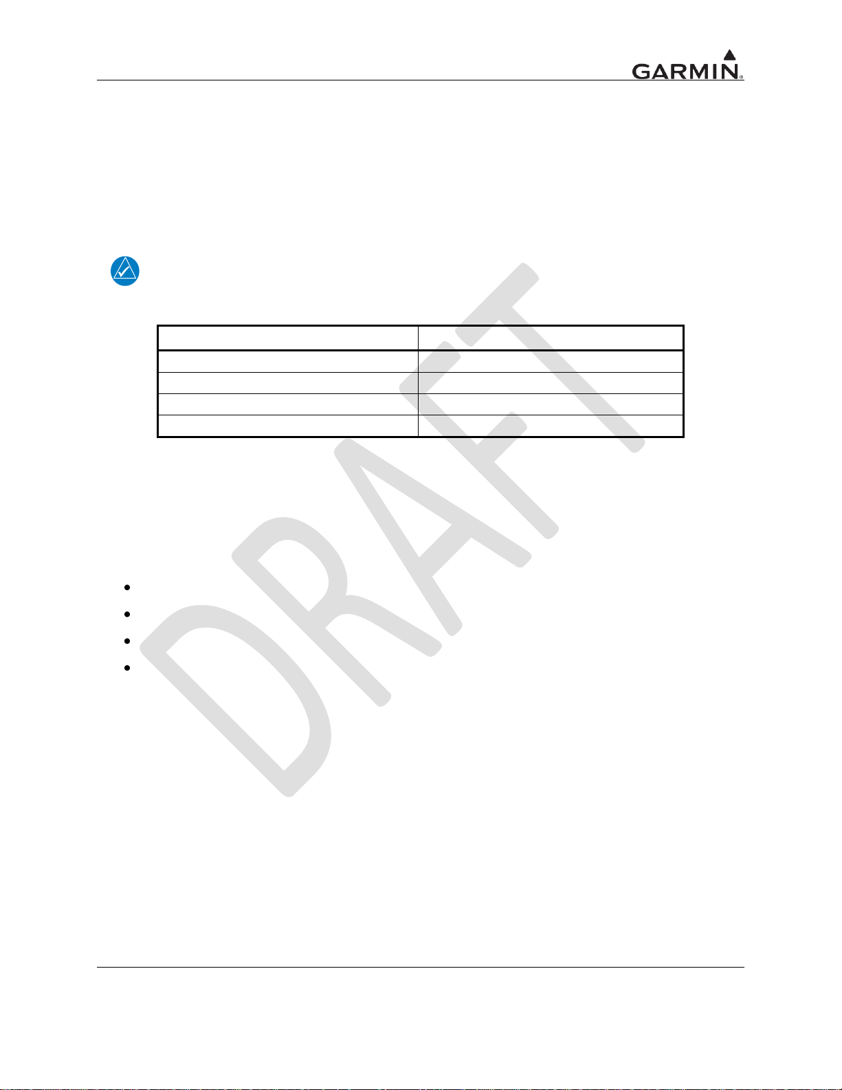
Model
Part Number
GDL 88
010-00859-00
GDL 88 with GPS/SBAS
010-00860-00
GDL 88D
010-00861-00
GDL 88D with GPS/SBAS
010-00862-00
1.1 Introduction
This manual is applicable for GDL 88 units with software version 2.00 or later. This manual describes the
physical, mechanical, and electrical characteristics, as well as instructions and other conditions and
limitations for installation and approval of the GDL units. Refer to Section 2, Limitations, for additional
information and other considerations.
NOTE
Except where specifically notes, references made to GDL 88 will equally apply to
GDL 88 with GPS/SBAS, GDL 88D, and GDL 88D with GPS/SBAS units.
Table 1-1. GDL 88 Units
1.2 Equipment Description
The GDL 88 is a remote-mounted product that contains a 978 MHz Universal Transceiver (UAT) and a
1090 MHz receiver. The GDL 88 will transmit ownship ADS-B data via the UAT data link. It will receive
data from other UAT and 1090ES equipped aircraft, as well as Flight Information Service Broadcast
(FIS-B) weather. The received data may be output to an appropriate display.
The GDL 88 Series consist of four variations:
GDL 88
GDL 88, with an internal GPS/SBAS receiver
GDL 88D with dual antenna diversity
GDL 88D, with dual antenna diversity and an internal GPS/SBAS receiver
GDL 88 TSO Installation Manual Page 1-1
190-01122-00 Rev. A
Page 10
Characteristics
Specifications
Height
Width
Depth (Installed with rack and connectors)
GDL 88 Weight (Unit only)
GDL 88 Weight (Installed with rack)
GDL 88 with GPS/SBAS Weight (Installed with rack)
GDL 88D Weight (Unit only)
GDL 88D Weight (Installed with rack)
GDL 88D with GPS/SBAS Weight (Unit Only)
GDL 88D with GPS/SBAS Weight (Installed with rack)
Characteristics
Specifications
Operating Temperature Range
-45°C to +70°C For more details see
Environmental Qualification Form on the
Dealers Only page on www.garmin.com. See
Appendix A for part numbers.
Humidity
95% at 65°C
Altitude Range
50,000 ft (maximum)
Input Voltage Range
9 to 33 VDC
External Cooling
External fan incorporated into GDL 88
backplate is required.
Environmental Testing
See Environmental Qualification Form on the
Dealers Only page on www.garmin.com. See
Appendix A for part numbers.
1.3 Technical Specifications
1.3.1 Physical Characteristics
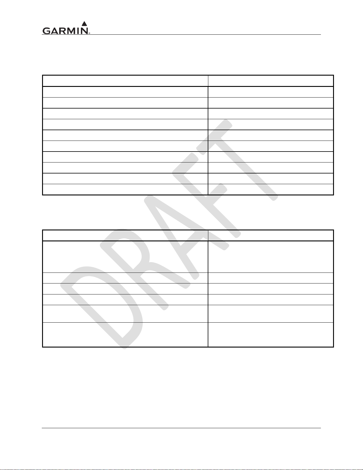
Table 1-2. Physical Characteristics – GDL 88 Units
1.3.2 General Specifications
Table 1-3. General Specifications - GDL 88 Units
Page 1-2 GDL 88 TSO Installation Manual
Rev. A 190-01122-00
Page 11
1.3.3 GPS/SBAS Specifications
Characteristics
Specifications
Number Of Channels
15 (12 GPS and 3 SBAS)
Frequency
1575.42 MHz L1, C/A code
Sensitivity
(Acquisition, No Interference)
-134.5 dBm GPS
-135.5 dBm WAAS
Sensitivity (Drop Lock)
-144 dBm
Dynamic Range
> 20 dB
Lat/Lon Position Accuracy
<1.25 meter RMS horizontal, <2 meter vertical, with WAAS
Velocity
1000 knots maximum (above 60,000 ft)
TTFF (Time To First Fix)
1:45 min. typical with current almanac, position, and time
Reacquisition
10 seconds typical
Position Update Interval
0.2 sec (5 Hz)
1 PPS (Pulse Per Second)
275 Nsec of UTC second
Datum
WGS-84
SATCOM Compatibility
SATCOM compatibility is dependent upon antenna selection.
Antenna Power Supply
35 mA typical, 40 mA max at 4.7 VDC
Characteristics
Specifications
Frequency
978.00 MHz
Transmit Power
50 W (+47 dBm)
Frequency Tolerance
+ 20 PPM
Modulation
Continuous Phase FSK, h = 0.6, Raised Cosine shaping, a = 0.5
Data Rate
1.04 Mbps
99% Power Bandwidth
1.3 MHz
60 dB Bandwidth
3.3 MHz (estimated)
Receiver Sensitivity
-96 dBm for 90% MSR
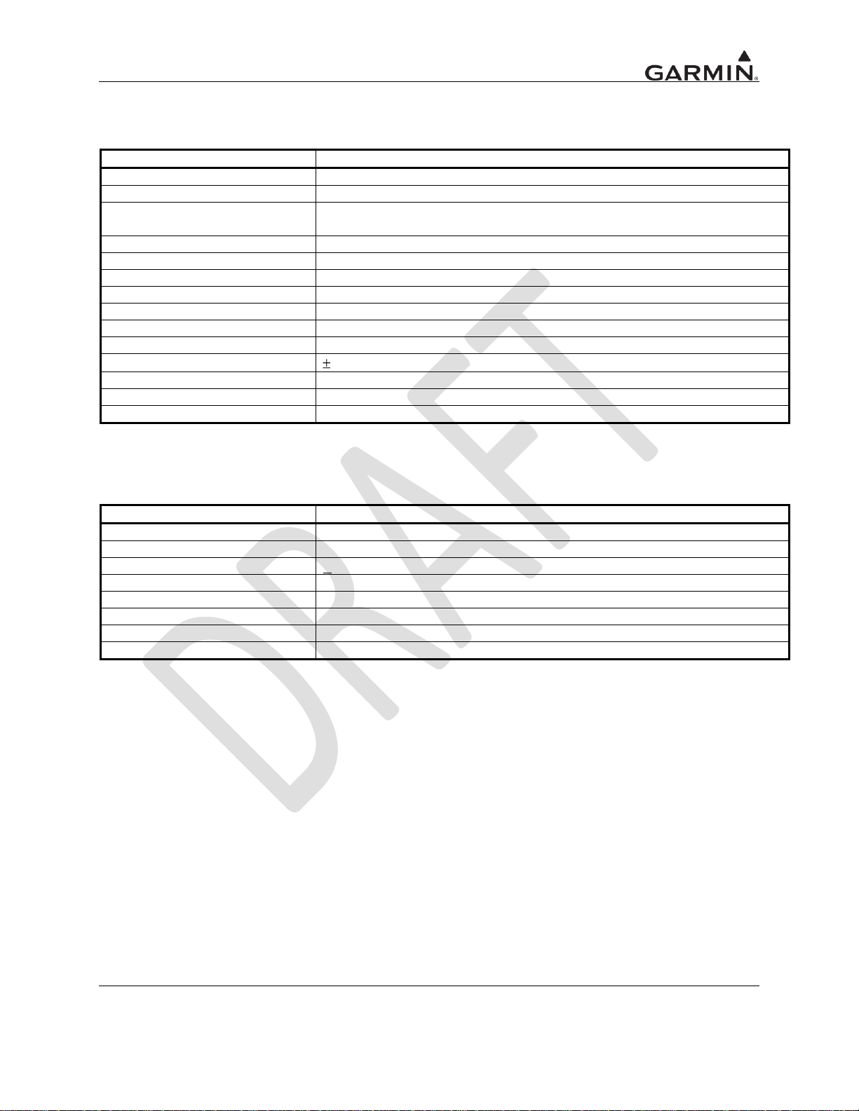
Table 1-4. GPS/SBAS Specifications – GDL 88 and GDL 88D with GPS/SBAS
1.3.4 978 MHz UAT Transceiver Specifications
Table 1-5. UAT Transceiver Specifications
GDL 88 TSO Installation Manual Page 1-3
190-01122-00 Rev. A
Page 12
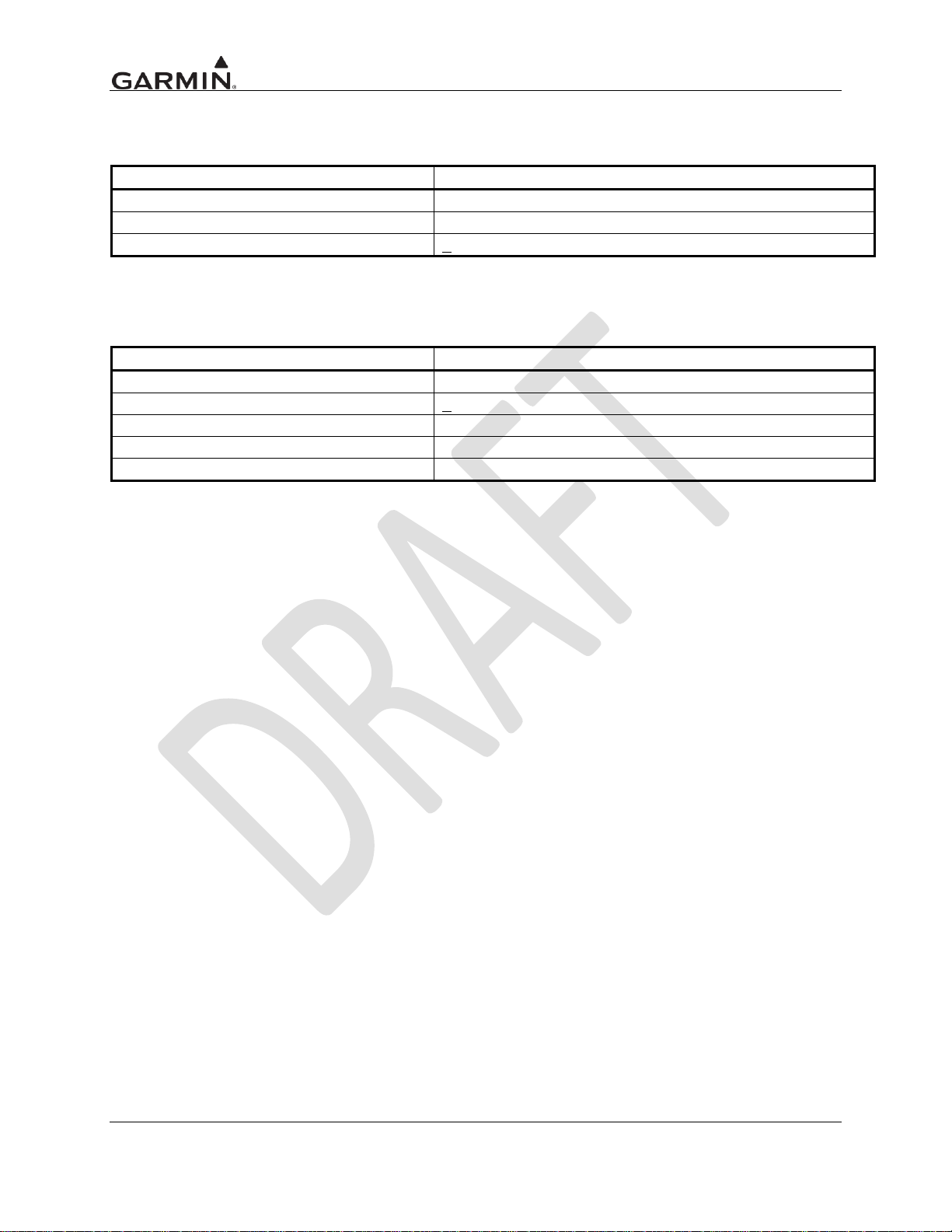
Characteristics
Specifications
Frequency
1030 MHz
Transmit Power
-29 dBm
Frequency Tolerance
+ 20 kHz
Characteristics
Specifications
Frequency
1090 MHz
Frequency Tolerance
+ 1 MHz
Modulation
Binary Pulse-Position
Data Rate
1 Mbps
Sensitivity
-82 dBm for 90% MSR
1.3.5 1030 MHz Transmitter Specifications
Table 1-6. Transmitter Specifications
1.3.6 1090 MHz Receiver Specifications
Table 1-7. Receiver Specifications
Page 1-4 GDL 88 TSO Installation Manual
Rev. A 190-01122-00
Page 13
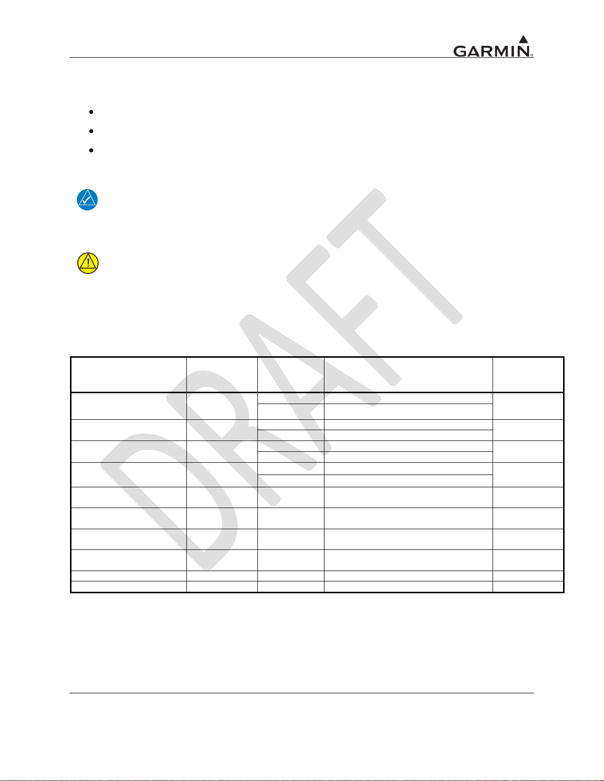
1.3.7 UAT/1090 Requirements
Model/Description
Conn Type
Mfr
Part Number
Garmin
Order
Number
GA 35, GPS/WAAS
[1]
TNC
Garmin
013-00235-( )
013-00235-( )
Aero Antenna
AT575-93G( )-TNCF-000-RG-27-NM
GA 36, GPS/WAAS
TNC
Garmin
013-00244-( )
013-00244-( )
Aero Antenna
AT575-126G( )-TNCF-000-RG-27-NM
GA 37, GPS/WAAS/XM
TNC
Garmin
013-00245-( )
013-00245-( )
Aero Antenna
AT2300-126G( )-TNCF-000-RG-27-NM
A33W, WAAS Antenna
TNC
Garmin
013-00261-( )
013-00261-( )
Aero Antenna
AT575-332G( )- TNCF-000-RG-27-NM
GPS/VHF Antenna
TNC/BNC
[2]
Comant
CI-2580-200
N/A
GPS/VHF Antenna
TNC/BNC
[2]
Comant
CI-2728-200
N/A
GPS/XM/VHF Antenna
TNC/TNC/BNC
[3]
Comant
CI-2580-410
N/A
GPS/XM/VHF Antenna
TNC/TNC/BNC
[3]
Comant
CI-2728-410
N/A
GPS/WAAS Antenna
TNC
Comant
CI-428-200
N/A
GPS/XM Antenna
TNC/TNC
Comant
CI-428-410
N/A
The GDL 88 requires UHF antenna(s) meeting the following specifications:
Vertically polarized
The VSWR produced by the antenna does not exceed 1.7:1 at 978 MHz and 1.5:1 at 1090 MHz.
TSO-C66, TSO-C74, or TSO-C112 antennas that also meet the VSWR specification.
NOTE
Certain types of transponder antennas that utilize very thin radiator elements are only
intended for use at 1030 and 1090 MHz. These types of antennas should be evaluated on
a model-by-model basis to determine their suitability as UAT data link antennas.
CAUTION
Operating the GDL 88 without RF terminations on the top or bottom UAT antenna ports
can result in equipment damage. Always operate the GDL 88 with the top and bottom
UAT antenna ports terminated with a VSWR ration of 3.0:1 or less.
1.3.8 GPS Antenna Requirements
Antenna performance is critical to the GPS/SBAS operation. The antennas listed in Table 1-8 provide
acceptable performance with the GDL 88.
Table 1-8. Approved GPS/SBAS Antennas
[1] Same mounting hole pattern as GA 56, but GA 35 antenna has a physically larger footprint.
[2] The antenna connector is a TNC type. The VHF connector is a BNC type.
[3] The antenna connector is a TNC type. The XM connector is a TNC type. The VHF connector is a
BNC type.
GDL 88 TSO Installation Manual Page 1-5
190-01122-00 Rev. A
Page 14

1.4 License Requirements
The Telecommunications Act of 1996, effective February 8, 1996, provides the FCC discretion to
eliminate radio station license requirements for aircraft and ships. The GTN 750 installations must
comply with current transmitter licensing requirements. In the US, to find out the specific details on
whether a particular installation is exempt from licensing, please visit the FCC web site
http://wireless.fcc.gov/aviation. If an aircraft license is required, make application for a license on FCC
form 404, Application for Aircraft Radio Station License. The FCC also has a fax-on-demand service to
provide forms by fax. Outside the US, contact the responsible telecommunication authority. The
GTN 750 owner accepts all responsibility for obtaining the proper licensing before using the transceiver.
The maximum transmitting power, modulation identification, and frequency band information may be
required for licensing and are detailed in Section 1.4.4.
CAUTION
The VHF transmitter in this equipment is guaranteed to meet Federal Communications
Commission acceptance over the operating temperature range. Modifications not
expressly approved by Garmin could invalidate the license and make it unlawful to
operate the equipment.
NOTE
Canadian installations are required to meet Industry Canada specifications for maximum
radiation as documented in Radio Specifications Standard 102 (RSS-102). For more
information about RF exposure and related Canadian regulatory compliance, contact:
Manager, Radio Equipment Standards
Industry Canada
365 Laurier Avenue
Ottawa, Ontario
K1A 0C8
In accordance with Canadian Radio Specifications Standard 102 (RSS 102), RF field
strength exposure to persons from an antenna connected to this device should be limited
to 60V/m for controlled environment and 28 V/m for uncontrolled environment.
Page 1-6 GDL 88 TSO Installation Manual
Rev. A 190-01122-00
Page 15
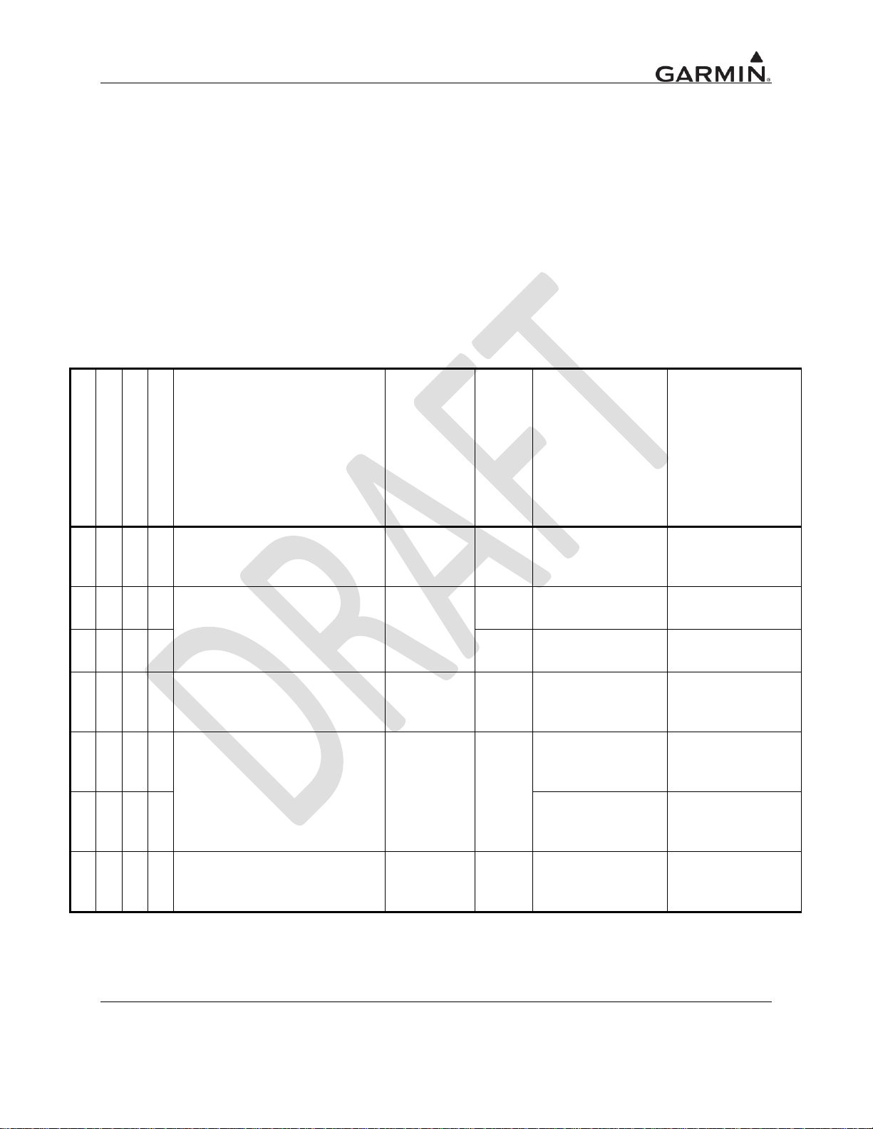
1.5 Regulatory Compliance
GDL 88
GDL 88D
GDL 88 w/ GPS/SBAS
GDL 88D w/ GPS/SBAS
Function
TSO/ETSO/
SAE/RTCA/
EUROCAE
Class/
Type
Applicable SW
P/Ns
Applicable CLD
P/Ns
C
C
Airborne Navigation Sensors
Using the Global Position System
Augmented by the Satellite Based
Augmentation System (SBAS)
TSO-C145c
DO-229D
B2
C
C
Universal Access Transceiver
(UAT) Automatic Dependent
Surveillance-Broadcast (ADS-B)
Equipment Operating on
Frequency of 978 MHz
TSO-C154c
DO-282B
A1H
C C
A1S
I I I
I
Aircraft Flight Information
Services – Broadcast (FIS-B)
Data Link Systems and
Equipment
TSO-C157
DO-267A
I
I
Extended Squitter Automatic
Dependent Surveillance –
Broadcast (ADS-B) and Traffic
Information Service – Broadcast
(TIS-B) Equipment Operating on
the Radio Frequency of 1090
Megahertz (MHz)
TSO-C166b
DO-260B
A1
I I
I I I
I
Avionics Supporting Automatic
Dependent Surveillance –
Broadcast (ADS-B) Aircraft
Surveillance Applications (ASA)
TSO-C195
DO-317
C1,
C2,
C3, C4
1.5.1 TSO Authorization and Advisory Circular References
The conditions and tests required for TSO approval of this article are minimum performance standards. It
is the responsibility of those installing this article either on or within a specific type or class of aircraft to
determine that the aircraft installation conditions are within the TSO standards. TSO articles must have
separate approval for installation in an aircraft. The article may be installed only in compliance with
14 CFR part 43 or the applicable airworthiness requirements.
All GTN unit functions are design approved under the TSO. Unauthorized changes or modifications to
any GTN unit product may void the compliance to required regulations and authorization for continued
equipment usage.
Table 1-9. TSO Authorization
C – Complete TSO I – Incomplete TSO
GDL 88 TSO Installation Manual Page 1-7
190-01122-00 Rev. A
Page 16
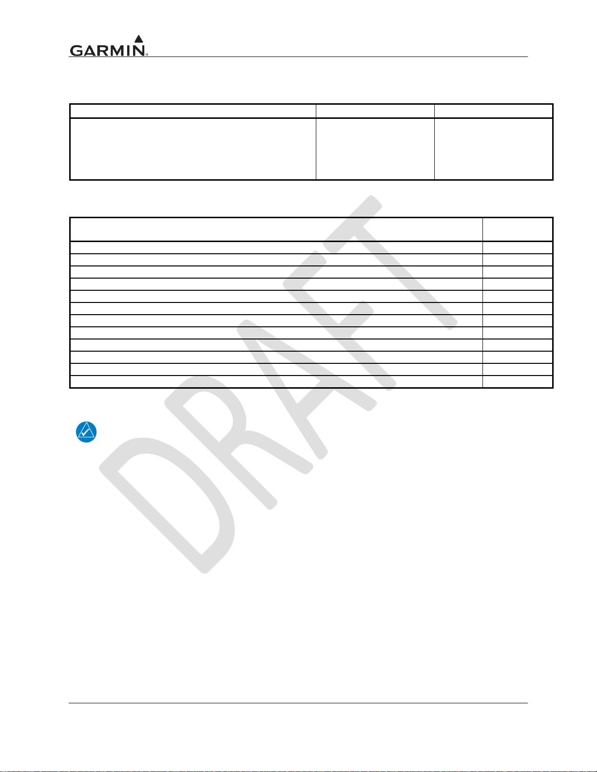
Function
Applicable SW P/N
Applicable CLD P/Ns
Transponder Self Interrogations:
The GDL 88 has the ability to transmit a low power Mode A
all call interrogation on the 1030 MHz frequency for the
purposes of receiving the squawk code and IDENT status
from a nearby Mode A, A/C, or S transponder on the 1090
MHz frequency.
System Function
DO-178B
Level
1.5.2 Non-TSO Functions
Table 1-10. Non-TSO Functions
Table 1-11. System Functions
NOTE
All GDL 88 unit functions are design approved under the TSO. Unauthorized changes or
modifications to any GDL 88 unit product may void the compliance to required
regulations and authorization for continued equipment usage.
Page 1-8 GDL 88 TSO Installation Manual
Rev. A 190-01122-00
Page 17
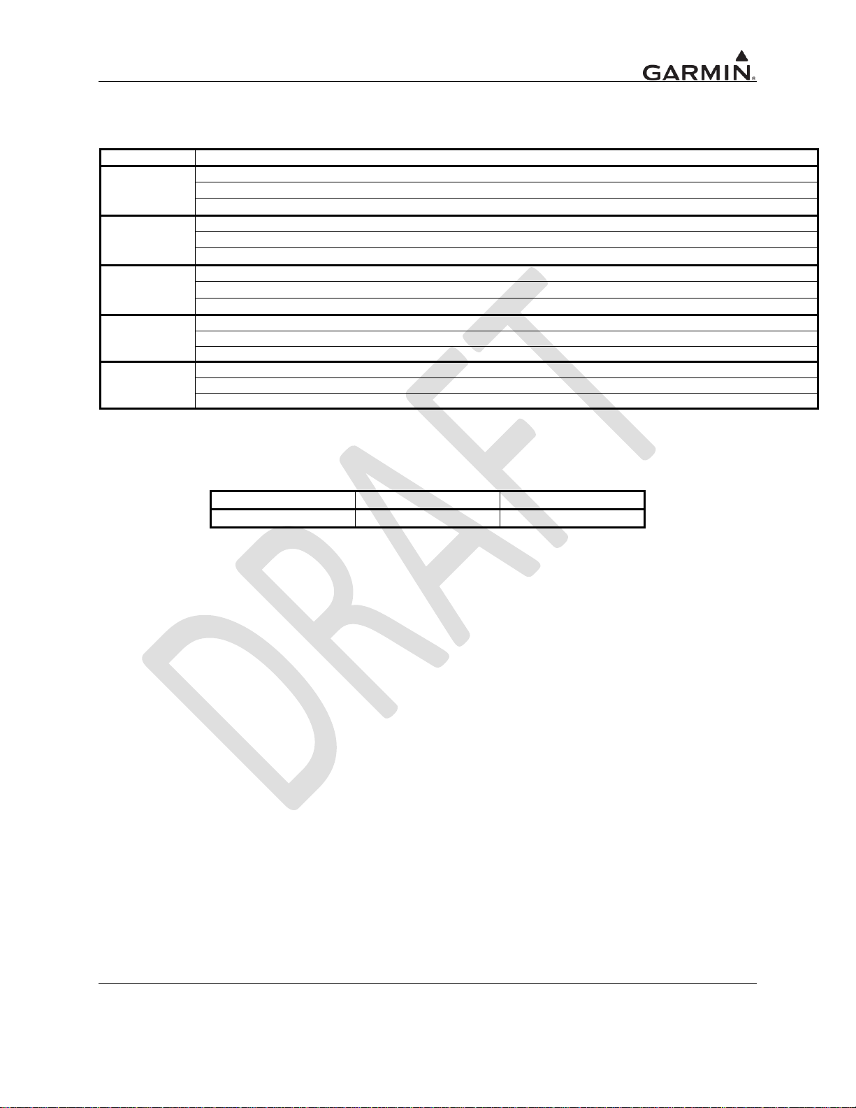
1.5.3 TSO Deviations
TSO
Deviation
TSO-C145c
TSO-C154c
TSO-C157
TSO-166b
TSO-C195
Model
FCC ID
IC ID
GDL 88
IPH-01246
1312A-01246
Table 1-12. TSO Deviations
1.5.4 FCC Grant of Equipment Authorization
Table 1-13. FCC and IC IDs
GDL 88 TSO Installation Manual Page 1-9
190-01122-00 Rev. A
Page 18

1.6 Aviation Limited Warranty
All Garmin avionics products are warranted to be free from defects in materials or workmanship for: two
years from the date of purchase for new Remote-Mount and Panel-Mount products; one year from the
date of purchase for new portable products and any purchased newly-overhauled products; six months for
newly-overhauled products exchanged through a Garmin Authorized Service Center; and 90 days for
factory repaired or newly-overhauled products exchanged at Garmin in lieu of repair. Within the
applicable period, Garmin will, at its sole option, repair or replace any components that fail in normal use.
Such repairs or replacement will be made at no charge to the customer for parts or labor, provided that the
customer will be responsible for any transportation cost. This warranty does not apply to: (i) cosmetic
damage, such as scratches, nicks and dents; (ii) consumable parts, such as batteries, unless product
damage has occurred due to a defect in materials or workmanship; (iii) damage caused by accident, abuse,
misuse, water, flood, fire, or other acts of nature or external causes; (iv) damage caused by service
performed by anyone who is not an authorized service provider of Garmin; or (v) damage to a product
that has been modified or altered without the written permission of Garmin. In addition, Garmin reserves
the right to refuse warranty claims against products or services that are obtained and/or used in
contravention of the laws of any country.
THE WARRANTIES AND REMEDIES CONTAINED HEREIN ARE EXCLUSIVE AND IN LIEU OF
ALL OTHER WARRANTIES, WHETHER EXPRESS, IMPLIED OR STATUTORY, INCLUDING
ANY LIABILITY ARISING UNDER ANY WARRANTY OF MERCHANTABILITY OR FITNESS
FOR A PARTICULAR PURPOSE, STATUTORY OR OTHERWISE. THIS WARRANTY GIVES
YOU SPECIFIC LEGAL RIGHTS, WHICH MAY VARY FROM STATE TO STATE.
IN NO EVENT WILL GARMIN BE LIABLE FOR ANY INCIDENTAL, SPECIAL, INDIRECT OR
CONSEQUENTIAL DAMAGES, WHETHER RESULTING FROM THE USE, MISUSE OR
INABILITY TO USE THE PRODUCT OR FROM DEFECTS IN THE PRODUCT. SOME STATES DO
NOT ALLOW THE EXCLUSION OF INCIDENTAL OR CONSEQUENTIAL DAMAGES, SO THE
ABOVE LIMITATIONS MAY NOT APPLY TO YOU.
Garmin retains the exclusive right to repair or replace (with a new or newly-overhauled replacement
product) the product or software or offer a full refund of the purchase price at its sole discretion. SUCH
REMEDY WILL BE YOUR SOLE AND EXCLUSIVE REMEDY FOR ANY BREACH OF
WARRANTY.
Online Auction Purchases: Products purchased through online auctions are not eligible for warranty
coverage. Online auction confirmations are not accepted for warranty verification. To obtain warranty
service, an original or copy of the sales receipt from the original retailer is required. Garmin will not
replace missing components from any package purchased through an online auction.
International Purchases: A separate warranty may be provided by international distributors for devices
purchased outside the United States depending on the country. If applicable, this warranty is provided by
the local in-country distributor and this distributor provides local service for your device. Distributor
warranties are only valid in the area of intended distribution. Devices purchased in the United States or
Canada must be returned to the Garmin service center in the United Kingdom, the United States, Canada,
or Taiwan for service.
Page 1-10 GDL 88 TSO Installation Manual
Rev. A 190-01122-00
Page 19

2 LIMITATIONS
2.1 Installation
The conditions and tests required for TSO approval of this article are minimum performance standards. It
is the responsibility of those installing this article either on or within a specific type or class of aircraft to
determine that the aircraft installation conditions are within the TSO standards. TSO articles must have
separate approval for installation in an aircraft. The article may be installed only if performed under
14 CFR part 43 or the applicable airworthiness requirements.
The GDL 88 GPS/SBAS receiver, when installed with an appropriate antenna listed in Section 1.3.8, is
compatible with aircraft equipped with SATCOM when installed in accordance to this manual.
GDL 88 TSO Installation Manual Page 2-1
190-01122-00 Rev. A
Page 20

3 INSTALLATION OVERVIEW
Always follow acceptable avionics installation practices per AC 43.13-1B, AC 43.13-2B, or later FAA
approved revisions of these documents. The GPS/SBAS installation instructions have been prepared to
meet the guidance material contained in AC 20-138A “Airworthiness Approval of Global Navigation
Satellite System (GNSS) Equipment.” The communications installation instructions have been prepared
to meet the guidance material defined by AC 20-67B, “Airborne VHF Communications Equipment
Installations.”
3.1 Antenna Considerations
This section contains mounting location considerations for the antennas required for the GDL 88 units.
For mounting the GPS/SBAS antenna, refer to FAA approved data. For mounting the NAV antennas,
refer to the aircraft manufacturer‟s data.
3.1.1 GPS Antenna Location
The GPS/SBAS antenna is a key element in the overall system performance and integrity for a
GPS/SBAS navigation system. The mounting location, geometry, and surroundings of the antenna can
affect the system performance and/or availability. The following guidance provides information to aid the
installer in ensuring that the most optimum location is selected for the installation of the GPS antenna.
The installation guidelines presented here meet the intent of AC 20-138A section 16. The greater the
variance from these guidelines, the greater the chance of decreased availability. Approach procedures
with vertical guidance are the most sensitive to these effects. LNAV only approaches, terminal
operations, and en route operations may also be affected. Because meeting all of these installations
guidelines may not be possible on all aircraft, these guidelines are listed in order of importance to achieve
optimum performance. Items 3 below are of equal importance and their significance may depend on the
aircraft installation. The installer should use their best judgment to balance the installation guidelines.
Figure 3-1 shows the recommended placement of antennas.
1. Mount the antenna as close to level as possible with respect to the normal cruise flight attitude
of the aircraft. If the normal flight attitude is not known, substitute the waterline, which is
typically referenced as level while performing a weight and balance check.
2. The GPS antenna should be mounted in a location to minimize the effects of airframe
shadowing during typical maneuvers. Typically mounting farther away from the tail section
reduces signal blockage seen by the GPS antenna.
3a. The GPS antenna should be mounted no closer than two feet from any VHF COM antenna or
any other antenna which may emit harmonic interference at the L1 frequency of
1575.42 MHz. An aircraft EMC check (reference VHF COM interference check in Post
Installation Checkout procedures) can verify the degradation of GPS in the presence of
interference signals. If an EMC check reveals unacceptable interference, insert a GPS notch
filter in line with the offending VHF COM or the (re-radiating) ELT transmitter.
NOTE
When mounting a combination antenna (ex. GPS and COM, GPS and XM), the
recommended distance of two feet or more is not applicable to the distance between the
antenna elements provided the combination antenna is TSO authorized and has been
tested to meet Garmin‟s minimum performance standards.
Page 3-2 GDL 88 TSO Installation Manual
Rev. A 190-01122-00
Page 21

3b. The GPS antenna should be mounted no closer than two feet from any antennas emitting more
than 25 watts of power. An aircraft EMC check can verify the degradation of GPS in the
presence of interference signals.
3c. To achieve the best possible low-elevation antenna gain (by minimizing pattern degradation
due to shadowing and near-field interaction), the GPS antenna must be mounted with clearance
from other antennas, including passive antennas such as another GPS antenna or XM antenna.
When practical, installers will use 12 inch center-to-center spacing between antennas. If 12
inch spacing is not practical, installers will use the maximum center-to-center spacing from
adjacent antennas, but never less than 9 inch center-to-center spacing. Spacing less than 9
inches center-to-center results in unacceptable GPS/SBAS antenna pattern degradation.
4. To maintain a constant gain pattern and limit degradation by the windscreen, avoid mounting
the antenna closer than 3 inches from the windscreen.
5. For multiple GPS installations, the antennas should not be mounted in a straight line from the
front to the rear of the fuselage. Also varying the mounting location will help minimize any
aircraft shading by the wings or tail section (in a particular azimuth, when one antenna is
blocked the other antenna may have a clear view).
GDL 88 TSO Installation Manual Page 3-3
190-01122-00 Rev. A
Page 22
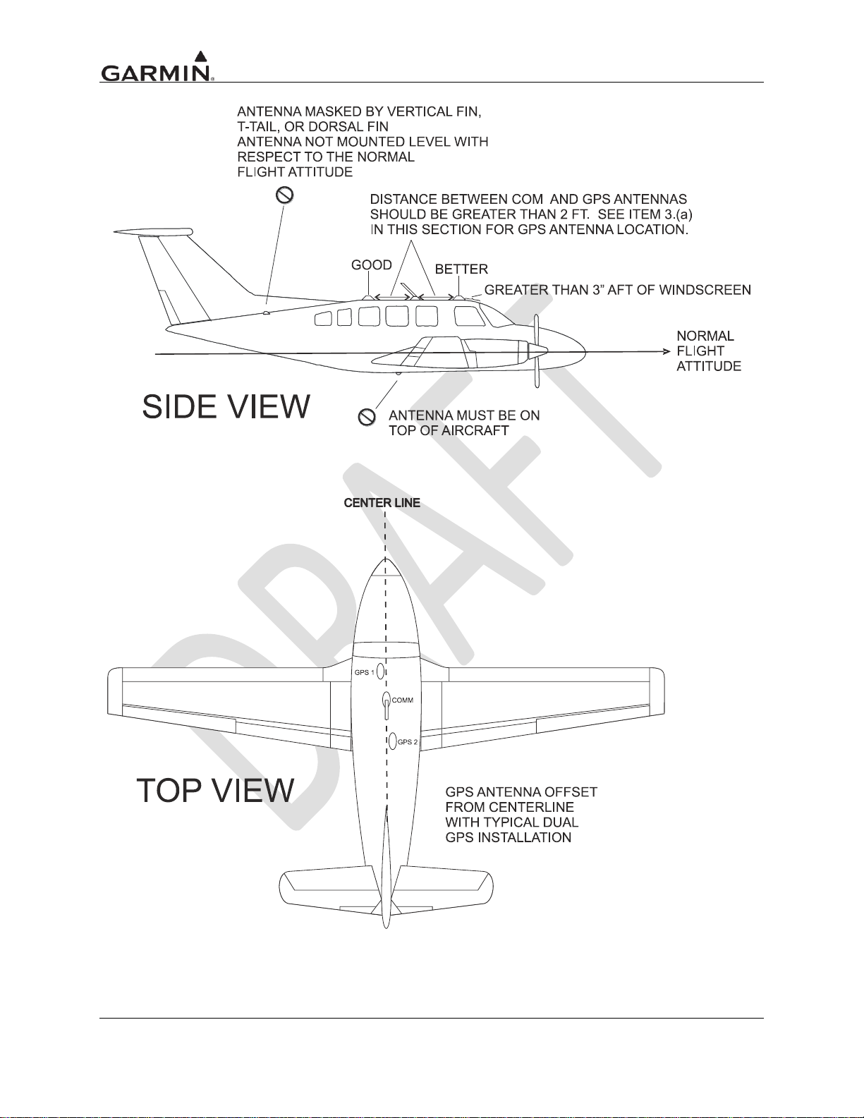
Figure 3-1. GPS Antenna Installation Considerations
Page 3-4 GDL 88 TSO Installation Manual
Rev. A 190-01122-00
Page 23
4 INSTALLATION PROCEDURES
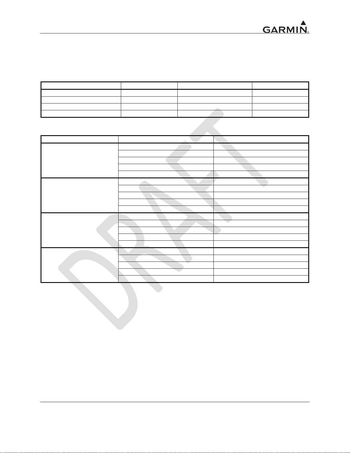
Model
Unit Only Kit
Standard Kit
Unit P/N
GDL 88
010-00859-00
010-00859-30
011-02369-00
GDL 88 with GPS/SBAS
010-00860-00
010-00860-30
011-02370-00
GDL 88D
010-00861-00
010-00861-30
011-02371-00
GDL 88D with GPS/SBAS
010-00862-00
010-00862-30
011-02372-00
Model
Item
Part Number
GDL 88
Configuration Module Kit
011-00979-00
Backplate Assembly
011-01718-00
Connector Kit
011-02375-00
Remote Rack Assembly
115-01035-00
Installation Kit
011-02621-00
GDL 88 with GPS/SBAS
Configuration Module Kit
011-00979-00
Backplate Assembly
011-01718-10
Connector Kit
011-02375-00
Remote Rack Assembly
115-01035-00
Installation Kit
011-02621-00
GDL 88D
Configuration Module Kit
011-00979-00
Backplate Assembly
011-01718-20
Connector Kit
011-02375-00
Remote Rack Assembly
115-01035-00
Installation Kit
011-02621-00
GDL 88D with GPS/SBAS
Configuration Module Kit
011-00979-00
Backplate Assembly
011-01718-30
Connector Kit
011-02375-00
Remote Rack Assembly
115-01035-00
Installation Kit
011-02621-00
4.1 Unit and Accessories
For description of units, see Table 1-1.
Table 4-1. Catalog Part Numbers
Table 4-2. Standard Kit Accessories
GDL 88 TSO Installation Manual Page 4-1
190-01122-00 Rev. A
Page 24
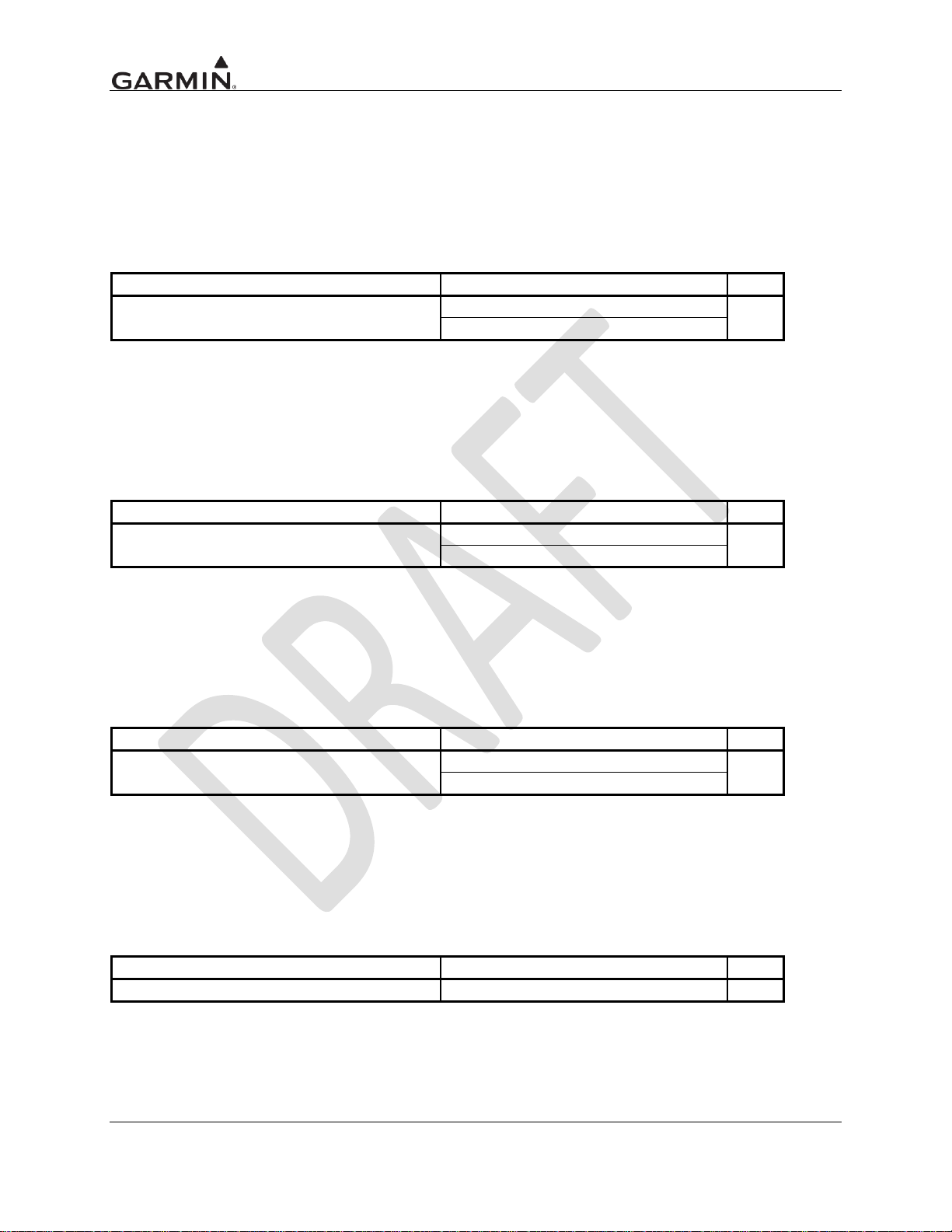
Item
Part Number
Qty
GA 35 GPS/ WAAS Antenna [1]
013-00235-00 (Garmin)
1
AT575-93G (Aero Antenna)
Item
Part Number
Qty
GA 36 GPS/WAAS Antenna [1]
013-00244-00 (Garmin)
1
AT575-126G (Aero Antenna)
Item
Part Number
Qty
GA 37 GPS/WAAS + XM Antenna [1]
013-00245-00 (Garmin)
1
AT2300-126G (Aero Antenna)
Item
Part Number
Qty
A33W, WAAS [1]
013-00261-00 (Garmin)
1
4.2 Optional Accessories
4.2.1 GPS Antenna Options
For details regarding antenna selection, refer to Section 1.3.8. Once the antenna type is decided upon,
refer to the information below for detailed parts information for antennas available directly from Garmin.
Contact the manufacturer directly for information on other antennas.
GA 35 Antenna:
GA 35 Antenna Garmin P/N 013-00235-00 contains the following items:
[1] Antenna includes 8-32 UNC-2A x 1.00” SS 303 mounting screws (qty 4) and O-ring (qty 1).
An antenna doubler may also be required. Refer to the appropriate antenna installation data.
To secure the antenna #8 washers (qty 4) and #8 (qty 4) self-locking nuts are required in addition to
the antenna, or suitable nutplates may be installed on the doubler.
To connect the GPS antenna coaxial cable to the antenna a TNC plug is required.
GA 36 Antenna:
GA 36 Antenna Garmin P/N 013-00244-00 contains the following items:
[1] Antenna includes 8-32 UNC-2A x 1.00” SS 303 mounting screws (qty 4) and O-ring (qty 1).
An antenna doubler may also be required. Refer to the appropriate antenna installation data.
To secure the antenna #8 washers (qty 4) and #8 (qty 4) self-locking nuts are required in addition to
the antenna, or suitable nutplates may be installed on the doubler.
To connect the GPS antenna coaxial cable to the antenna a TNC plug is required.
GA 37 Antenna:
GA 37 Antenna Garmin P/N 013-00245-00 contains the following items:
[1] Antenna includes 8-32 UNC-2A x 1.00” SS 303 mounting screws (qty 4) and O-ring (qty 1).
An antenna doubler may also be required. Refer to the appropriate antenna installation data.
To secure the antenna #8 washers (qty 4) and #8 (qty 4) self-locking nuts are required in addition to
the antenna, or suitable nutplates may be installed on the doubler.
To connect the GPS antenna coaxial cable to the antenna a TNC plug is required.
A33W Antenna:
A33W Antenna Garmin P/N 013-00261-00 contains the following items:
[1] Antenna includes 6-32 UNC-2A x 1.00” SS 303 mounting screws (qty 4) and O-ring (qty 1).
An antenna doubler may also be required. To secure the antenna, #6 washers (qty 4) and #6 (qty 4)
self-locking nuts are required in addition to the antenna, or suitable nutplates may be installed on the
doubler that is used. To connect the GPS antenna coaxial cable to the antenna a TNC plug is
required.
Page 4-2 GDL 88 TSO Installation Manual
Rev. A 190-01122-00
Page 25
4.2.2 UAT Antenna Options
Item
Garmin P/N
Mfg P/N
Connector, BNC, Male, Clamp
330-00087-00
N/A
GPS 1.57542 GHz Notch Filter
330-00067-00
N/A
Connector, TNC, Male, Clamp
N/A
031-4452 [1]
Manufacturer
Hand Crimping
Tool
22 – 28 AWG (P1001 – P1005)
Positioner
Insertion/
Extraction Tool
Military P/N
M22520/2-01
M22520/2-09
M81969/14-01
M81969/1-04
Positronic
9507-0-0-0
9502-4-0-0
M81969/1-04
ITT Cannon
995-0001-584
995-0001-739
000849490
274-7048-000MIL
AMP
601966-1
601966-6
91067-1
2031838-1
Daniels
AFM8
K42
M81969/14-01
M81969/1-04
Astro
615717
615725
M81969/14-01
M81969/1-04
4.3 Miscellaneous Options
[1] This part is not available from Garmin.
Vendor Contact Information (provided for convenience only):
Amphenol RF, Four Old Newtown Road, Danbury, CT 06810 Phone: 800-627-7100
4.4 Installation Materials not Supplied
4.4.1 Installation Materials Required but not Supplied
The GDL 88 is intended for use with the standard aviation accessories. The following items are required
for installation, but not supplied.
Wire (MIL-W-22759/16 or equivalent)
Shielded Wire (MIL-C-27500 or equivalent)
Mounting Screws (8 minimum – MS24693 Screw, Machine, Flat Countersunk Head 100°, Cross-
recessed with .1380-32 UNC-2A Thread, Corrosion Resistant Steel)
Push/Pull (manually resettable) Circuit Breakers
Tie Wraps or Lacing Cord
Ring Terminals (for grounding)
Coaxial Cable (RG-400, RG-142B or equivalent – Refer to Section 4.11 for additional
information).
4.5 Special Tools Required
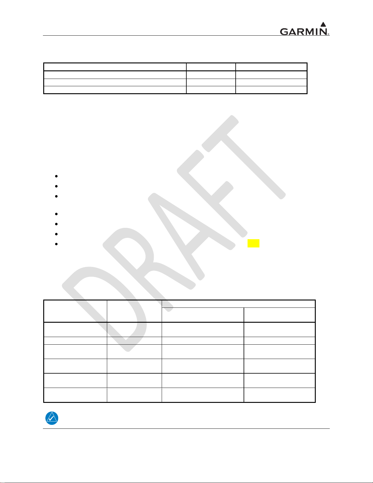
Some of the connectors use crimp contacts. The table below identifies crimp tools required to ensure
consistent, reliable crimp contact connections for the rear D-sub connectors.
Table 4-3. Recommended Crimp Tools (or Equivalent)
NOTE
Insertion/extraction tools from ITT Cannon are all plastic; others are plastic with metal tip.
GDL 88 TSO Installation Manual Page 4-3
190-01122-00 Rev. A
Page 26
GASKET
NUT
9
16
3
16
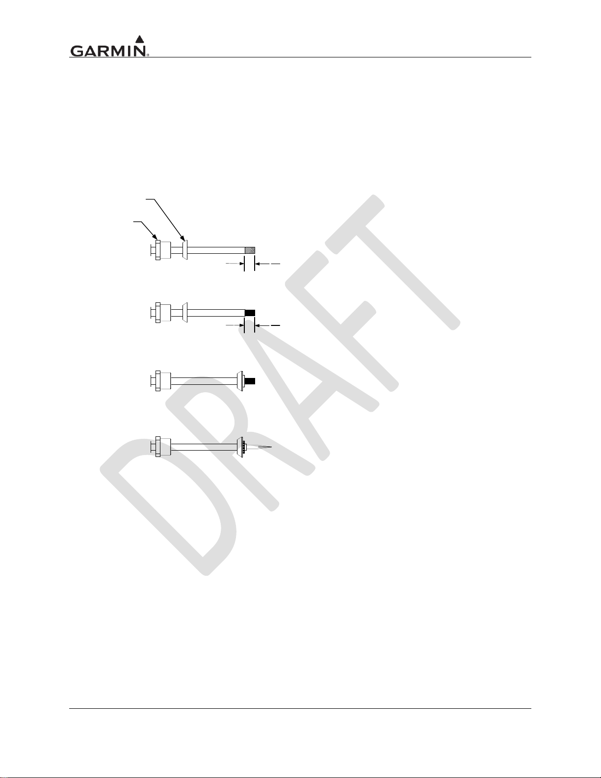
1. PLACE NUT AND GASKET OVER CABLE AND STRIP JACKET
TO DIMENSION SHOWN.
2. COMB OUT BRAID AND TRIM DIELECTRIC TO
DIMENSION SHOWN.
3. PULL BRAID WIRES FORWARD AND TAPER TOWARD CENTER
CONDUCTOR. PLACE CLAMP OVER BRAID AND PUSH BACK
AGAINST JACKET.
4. FOLD BACK BRAID OVER CLAMP AS SHOWN. TRIM OFF
EXCESS BRAID. SOLDER CONTACT TO CENTER CONDUCTOR.
5. INSERT CABLE CLAMP AND GASKET INTO CONNECTOR
BODY MAKING SURE THAT SHARP EDGE OF CLAMP SEATS
PROPERLY AND TIGHTEN NUT.
4.6 Coaxial Cable Installation
Follow the steps below for installation of the coaxial cables:
1. Route the coaxial cable to the radio rack location keeping in mind the recommendations of
Section 3.1. Secure the cable in accordance with AC 43.13-1B Chapter 11, section 11.
2. Trim the coaxial cable to the desired length and install the TNC and BNC connectors per the
cabling instructions on Figure 4-1 below. If the connector is provided by the installer, follow the
connector manufacturer‟s instructions for cable preparation.
Page 4-4 GDL 88 TSO Installation Manual
Figure 4-1. Coaxial Cable Installation
Rev. A 190-01122-00
Page 27
Wire Gauge
Configuration Module
78-pin Connector (P1001)
P1001-P1005
28 AWG [1]
22-28 AWG [2]
Garmin P/N
336-00021-00
336-00021-00
Military P/N
N/A
M39029/58-360
AMP
N/A
204370-2
Positronic
N/A
MC8522D
ITT Cannon
N/A
010-2042-000
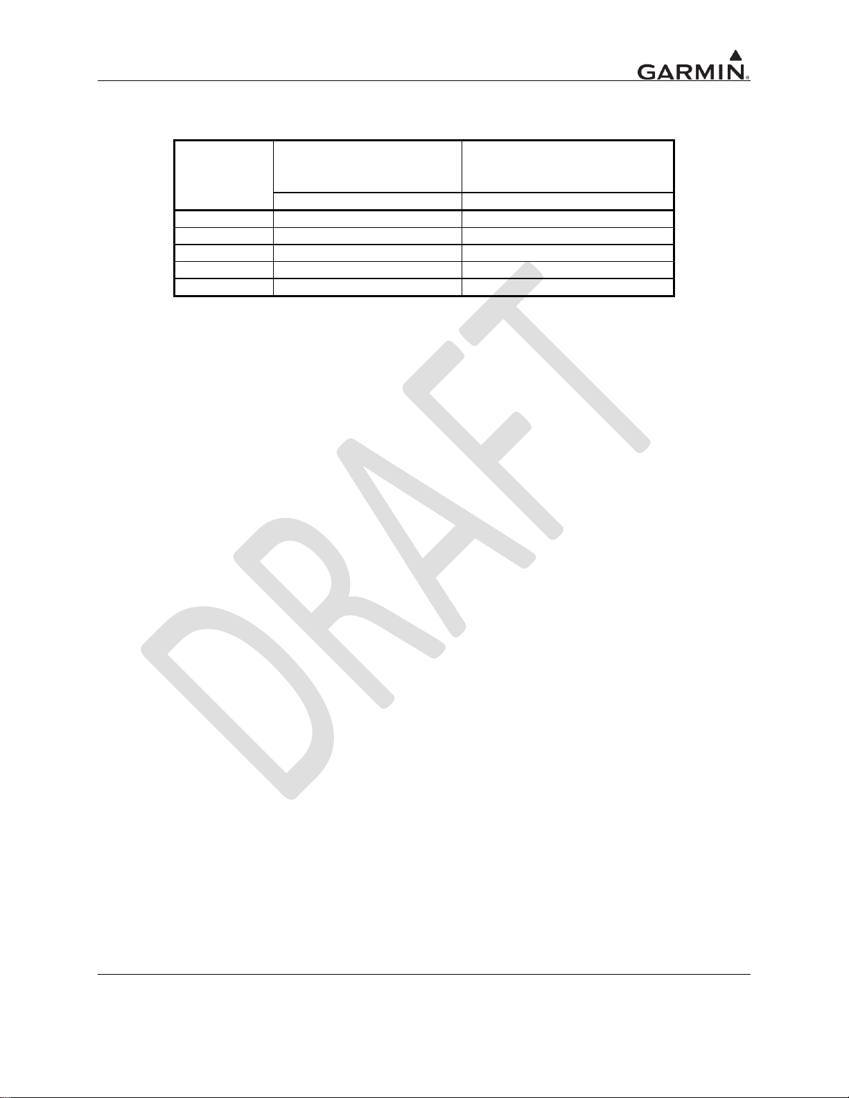
Table 4-4. Socket Contact Part Numbers
[1] For configuration module pins, ensure that the crimp tool is set to crimp 28 AWG wire
(indenter setting of „4‟).
[2] Contacts listed are not to be used for configuration module wiring. Use the contacts
supplied with the configuration module when installing configuration module wires in
P1001.
[3] Non-Garmin part numbers shown are not maintained by Garmin and are subject to
change without notice.
GDL 88 TSO Installation Manual Page 4-5
190-01122-00 Rev. A
Page 28

4.7 Equipment Mounting
4.7.1 Unit Replacement
4.8 Antenna Installation and Connections
This section provides information on the antenna cable installation. Refer to 3.1 herein for installation
location considerations.
SUGGESTION: Temporarily locate the GPS/SBAS antenna with coax connected to the GTN unit and
check the GPS/SBAS performance as described in Section. Once a suitable location has been verified,
then permanently mount the antenna.
Once the antenna mounting position has been prepared, route the coax cable from the antenna to the GTN
unit. Proper selection of coax cable and assembly of connectors is critical to GPS signal performance.
Cable loss from the GPS/SBAS antenna must be between 1.5 dB and 6.5 dB in order to maintain
proper rejection to interference signals.
Coaxial connectors and adapters, such as TNC to BNC, add additional loss to the cable and should be
considered when computing the cable loss. A typical loss of 0.2 dB can be used for each connection. To
maintain integrity of the SBAS signal, the GPS antenna coaxial cable must have a minimum of two
shields (e.g. RG-400 or RG-142B).
NOTE
If RG-142B or RG-400 is used, 1.5 dB equates to a length of approximately 6.5 feet of
cable with a connector on each end. RG-142B or RG-400 cable can be used as long as
the length is less than 35 feet. For longer lengths, use low-loss double or triple shielded
50 coax.
For very short runs, where the loss is less than 1.5 dB, additional cable should be used to increase the loss
to within 1.5 dB to 6.5 dB. This additional cable may be coiled, taking into account the minimum bend
radius of the cable.
During the post-installation checkout, susceptibility to harmonics of VHF COM transmitters will be
evaluated. If problems arise, then better isolation, or distance, may be required between the GPS and
COM antennas, or a 1575.42 MHz notch filter may be installed in series with the antenna coax of the
VHF COM transceiver to reduce or eliminate the harmonic interference. A notch filter for this use
(P/N 330-00067-00) is available from Garmin.
If a VHF COM transmitter causes problems with the GPS on the selected frequencies as listed in the postinstallation checkout, the problem may be due to the ELT. This can be verified by disconnecting the ELT
antenna coax at the ELT unit. If the ELT is found to cause the problem, then contact the ELT
manufacturer or replace the ELT.
Page 4-6 GDL 88 TSO Installation Manual
Rev. A 190-01122-00
Page 29
5 CONNECTOR PINOUT INFORMATION
1
2
345678910111314151617181920
2223242526
27
282930313233343536373839
4041
21
42434445
46
47484950515253545556575859
606162
636465
66
676869707172737475767778
Pin
Pin Name
I/O
1
RESERVED
--
2
RS-232 OUT 5
I/O
3
TIME MARK 1B
I/O
4
AUDIO OUT HI
Out
5
RS-232 OUT 4
Out
6
RS-232 OUT 3
Out
7
RS-232 OUT 2
Out
8
RS-232 OUT 1
Out
9
TIME MARK 2B
I/O
10
ARINC 429 OUT 1A
Out
11
ARINC 429 OUT 2A
Out
12
FAN SPEED
In
13
AUDIO ACTIVE OUT*
Out
14
ADS-B DEVICE FAIL*
Out
15
ADS-B FUNCTION FAIL
Out
16
AIR/GROUND*
In
17
REMOTE POWER ON*
In
18
GROUND
In
19
AIRCRAFT POWER
In
20
AIRCRAFT POWER
In
21
RS-232 IN 5
In
22
TIME MARK 1A
I/O
23
AUDIO OUT LO
Out
24
RS-232 IN 4
In
25
RS-232 IN 3
In
26
RS-232 IN 2
In
27
RS-232 IN 1
In
28
TIME MARK 2A
I/O
29
ARINC 429 OUT 1B
Out
30
ARINC 429 OUT 2B
Out
31
FAN POWER (5V)
Out
32
RS-422 IN 2A
In
33
RS-422 IN 2B
In
34
RS-422 OUT 2A
Out
35
RS-422 OUT 2B
Out
36
IDENT*
In
37
AUDIO INHIBIT IN*
In
38
PRESSURE ALT BROADCAST INHIBIT*
In
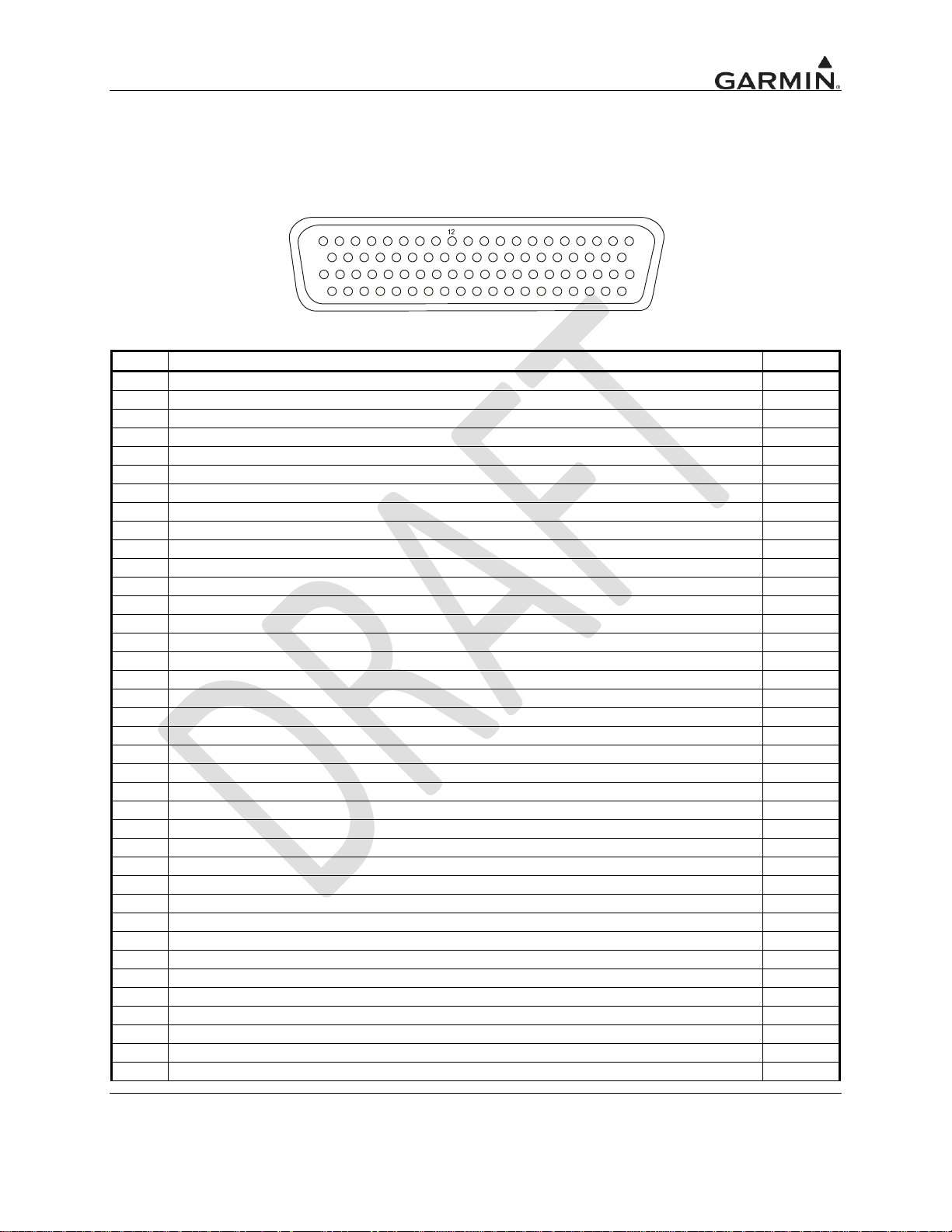
5.1 Pin Function List
5.1.1 P881 Connector
View looking at rear of unit, Pin X is top X
Table 5-1. P881 Connector
GDL 88 TSO Installation Manual Page 5-1
190-01122-00 Rev. A
Page 30
P881 Connector Cont’d
Pin
Pin Name
I/O
39
SPARE*
In
40
RS-232 GND 5
In
41
USB GROUND
In
42
USB VBUS POWER
In
43
RS-232 GND 4
In
44
RS-232 GND 3
In
45
RS-232 GND 2
In
46
RS-232 GND 1
In
47
ARINC 429 IN 2A
In
48
ARINC 429 IN 1A
In
49
ARINC 429 IN 3A
In
50
FAN GROUND
In
51
ETHERNET IN 1A
In
52
ETHERNET IN 1B
In
53
ETHERNET OUT 1A
Out
54
ETHERNET OUT 1B
Out
55
PRESSURE ALT BROADCAST ANNUN*
Out
56
RS-422 OUT 1A
Out
57
RS-422 IN 1A
In
58
TEST MODE*
In
59
SUPPRESSION
Out
60
USB DATA LO
I/O
61
USB DATA HI
I/O
62
CONFIG MODULE DATA
I/O
63
CONFIG MODULE CLOCK
Out
64
CONFIG MODULE GND
In
65
CONFIG MODULE POWER
Out
66
ARINC 429 IN 2B
In
67
ARINC 429 IN 1B
In
68
ARINC 429 IN 3B
In
69
GROUND
In
70
ETHERNET IN 2A
In
71
ETHERNET IN 2B
In
72
ETHERNET OUT 2A
Out
73
ETHERNET OUT 2B
Out
74
RESERVED
--
75
RS-422 OUT 1B
Out
76
RS-422 IN 1B
In
77
AIRCRAFT GND
In
78
AIRCRAFT GND
In
An asterisk (*) following a signal name denotes that the signal is an Active-Low, requiring a ground to
activate. If there is no asterisk, the signal is an Active-High.
Page 5-2 GDL 88 TSO Installation Manual
Rev. A 190-01122-00
Page 31
5.2 Power and Antennas
Pin Name
Connector
Pin
I/O
AIRCRAFT POWER
P881
19
In
AIRCRAFT POWER
P881
20
In
AIRCRAFT GND
P881
77
--
AIRCRAFT GND
P881
78
--
Pin Name
Connector
I/O
UAT ANTENNA – BOTTOM BNC
P882
I/O
UAT ANTENNA – TOP
P883
I/O
GPS/SBAS ANTENNA TNC
P884
In
This section covers the power input requirements and antenna connections. See Appendix D for
interconnect information.
5.2.1 Power
5.2.2 Antennas
UAT antenna(s) use BNC coaxial connectors on the connector backplate. The GPS/SBAS antenna uses a
TNC coaxial connector on the connector backplate.
GDL 88 TSO Installation Manual Page 5-3
190-01122-00 Rev. A
Page 32

6 POST INSTALLATION CONFIGURATION AND CHECKOUT
PROCEDURES
Page 6-4 GDL 88 TSO Installation Manual
Rev. A 190-01122-00
Page 33

GDL 88 TSO Installation Manual Page 6-5
190-01122-00 Rev. A
Page 34

Page 35

7 PERIODIC MAINTENANCE
This section contains information on periodic calibration and maintenance required for continued
airworthiness.
7.1 Equipment Calibration
No scheduled servicing tasks or internal manual adjustments are required on the GDL 88 units.
7.2 Cleaning
The GDL 88 units do not require regular cleaning.
7.3 Battery Replacement
The GDL 88 with GPS/SBAS and the GDL 88D with GPS/SBAS includes an internal battery that will
last about 10 years. The battery is used for internal RAM memory and GPS system information. Regular
planned replacement is not necessary. The battery is not user-replaceable. Battery replacement and
removal must be performed by professional services.
GDL 88 TSO Installation Manual Page 7-1
190-01122-00 Rev. A
Page 36

Page 7-2 GDL 88 TSO Installation Manual
Rev. A 190-01122-00
Page 37

Appendix A ENVIRONMENTAL QUALIFICATION FORM
For RTCA/DO-160F Environmental Qualification Forms (EQFs) visit the Dealers Only site on
http://www.garmin.com. The GDL 88 units all use the same EQF, part number 005-00358-20.
GDL 88 TSO Installation Manual Page A-1
190-01122-00 Rev. A
Page 38

Appendix B GDL 88 DATA FORMAT
B.1 GDL 88 RS-232 Fuel/Air Data Input Format
B.1.1 Electrical Interface
The input signals are compatible with RS-232C. Data input at 9600 baud (1200 baud for Apollo Altitude
Encoder) with a word length of 8 bits, one stop bit, and no parity. One message is received per second.
B.1.2 Icarus Altitude Sentence
The GDL 88 is capable of receiving the following 10-byte message from the Icarus Altitude Serializer:
ALT <sp>12345<CR>
Where:
ALT ASCII characters
<sp> space (0x20)
12345 altitude in feet
<CR> carriage return (0x0d)
B.1.3 Apollo Altitude Sentence
The GDL 88 is capable of receiving the following 17-byte message from an Apollo Altitude Encoder:
#AL<sp><+/->ddul<CR>
Where:
#AL ASCII characters
<sp> space (0x20)
<+/-> sign indicator (0x2B[“+”] or 0x2D[“-“])
ddddd altitude in feet (-1000 feet to 35,000 feet)
T ASCII characters
<+/-> sign indicator
dd sensor temperature
ul checksum of bytes 1 through 14 in hex ASCII (i.e. “FA”)
<CR> carriage return (0x0D)
Page B-2 GDL 88 TSO Installation Manual
Rev. A 190-01122-00
Page 39

B.1.4 Shadin Altitude Sentence
The GDL 88 is capable of receiving the following 17-byte message from Shadin Altitude Encoders,
Altitude Serializers, and Altitude Converters:
RMS<sp><+/->12345T<+/->12ul<CR>
Where:
RMS ASCII characters
<sp> space (0x20)
<+/-> sign indicator (0x2b["+"] or 0x2d["-"])
12345 altitude in feet
T ASCII character
<+/-> sign indicator
12 sensor temperature
ul checksum of bytes 1 through 14 in hex ASCII (i.e., "FA")
<CR> carriage return (0x0d)
Note: Checksum is calculated by adding each byte in the message (1 through 14).
GDL 88 TSO Installation Manual Page B-3
190-01122-00 Rev. A
Page 40

B.1.5 Shadin Fuel/Air Data Computer
The GDL 88 is capable of receiving the following message strings from the Shadin Fuel/Air Data or Air
Data Computer:
SHADIN “z” FORMAT
<STX>
ZA012<CR><LF> "ZA" (ASCII characters); "012" represents indicated Air Speed (knots)
ZB345<CR><LF> "ZB" (ASCII characters); "345" represents true Air Speed (knots)
ZC678<CR><LF> "ZC" (ASCII characters); "678" represents Mach Speed (thousandths)
ZD<+/->9012<CR><LF> "ZD" (ASCII characters); sign; "9012" represents pressure altitude (tens of
feet)
ZE<+/->3456<CR><LF> "ZE" (ASCII characters); sign; "3456" represents density altitude (tens of feet)
ZF<+/->78<CR><LF> "ZF" (ASCII characters); sign; "78" represents outside air temperature
(Celsius)
ZG<+/->90<CR><LF> "ZG" (ASCII characters); sign; "90" represents true air temperature (Celsius)
ZH123<CR><LF> "ZH" (ASCII characters); "123" represents wind direction (degrees from north)
ZI456<CR><LF> "ZI" (ASCII characters); "456" represents wind speed (knots)
ZJ<+/->78<CR><LF> "ZJ" (ASCII characters); sign; "78" represents rate of turn (degrees per second)
ZK<+/->901<CR><LF> "ZK" (ASCII characters); sign; "901" represents vertical speed (tens of
ft/minute)
ZL234<CR><LF> "ZL" (ASCII characters); "234" represents heading (degrees from north)
ZM5678<CR><LF>† "ZM" (ASCII characters); "5678" represents fuel flow, right (tenths
gallons/hour)
ZN90123<CR><LF>† "ZN" (ASCII characters); "90123" represents fuel used, right (tenths gallons)
ZO4567<CR><LF>† "ZO" (ASCII characters); "4567" represents fuel flow, left (tenths gallons/hour)
ZP89012<CR><LF>† "ZP" (ASCII characters); "89012" represents fuel used, left (tenths gallons)
ZQ345<CR><LF> "ZQ" (ASCII characters); "345" represents error log/reason indicator
ZR678<CR><LF> "ZR" (ASCII characters); "678" represents checksum
<ETX>
Where:
<STX> start-transmit character (0x02)
<CR> carriage-return character (0x0d)
<LF> line-feed character (0x0a)
<+/-> sign indicator (0x2b["+"] or 0x2d["-"])
<ETX> end-transmit character (0x03)
† Not available from Air Data Computer
Note: Checksum is calculated by adding each byte in the message (including all characters from <STX>
up to and including the error log/reason indicator), such that carries are discarded to give a one byte
result. The ASCII-coded decimal representation of that byte is given, ranging from 0 (0x30, 0x30, 0x30)
to 255 (0x32, 0x35, 0x35).
Page B-4 GDL 88 TSO Installation Manual
Rev. A 190-01122-00
Page 41

Appendix C MECHANICAL DRAWINGS
GDL 88 TSO Installation Manual Page C-5
190-01122-00 Rev. A
Page 42

Appendix D INTERCONNECT DIAGRAMS
Page D-6 GDL 88 TSO Installation Manual
Rev. A 190-01122-00
Page 43

GDL 88 TSO Installation Manual Page D-7
190-01122-00 Rev. A
Page 44

 Loading...