

Page 1
Owner’s Manual
marine radar
GMR 404/406
PRELIMINARY
PRELIMINARY
GMR 404_406 Owners Manual Preliminary Review.indd 1 3/27/2006 4:08:12 PM
Page 2
Garmin International, Inc.
1200 East 151st Street,
Olathe, Kansas 66062, U.S.A.
Tel. 913/397.8200 or 800/800.1020
Fax 913/397.8282
Garmin (Europe) Ltd.
Unit 5, The Quadrangle
Abbey Park Industrial Estate
Romsey, SO51 9DL, U.K.
Tel. 44/0870.8501241
Fax 44/0870.8501251
Garmin Corporation
No. 68, Jangshu 2nd Road
Shijr, Taipei County, Taiwan
Tel. 886/2.2642.9199
Fax 886/2.2642.9099
All rights reserved. Except as expressly provided herein, no part of this manual may be reproduced, copied, transmitted, disseminated, downloaded or stored in any
storage medium, for any purpose without the express prior written consent of Garmin. Garmin hereby grants permission to download a single copy of this manual onto
a hard drive or other electronic storage medium to be viewed and to print one copy of this manual or of any revision hereto, provided that such electronic or printed
copy of this manual must contain the complete text of this copyright notice and provided further that any unauthorized commercial distribution of this manual or any
revision hereto is strictly prohibited.
Information in this document is subject to change without notice. Garmin reserves the right to change or improve its products and to make changes in the content
without obligation to notify any person or organization of such changes or improvements. Visit the Garmin Web site (www.garmin.com) for current updates and
supplemental information concerning the use and operation of this and other Garmin products.
Garmin® is a registered trademarks of Garmin Ltd. or its subsidiaries and may not be used without the express permission of Garmin.
March 2006 Part Number 190-00669-00 Rev. A Printed in Taiwan
© Copyright 2006 Garmin Ltd. or its subsidiaries
PRELIMINARY
PRELIMINARY
GMR 404_406 Owners Manual Preliminary Review.indd 2 3/27/2006 4:08:12 PM
Page 3
GMR 404/406 Owner’s Manual i
INTRODUCTION
About This Manual
Thank you for choosing Garmin’s GMR 404/406 marine radar. The
addition of the GMR 404/406 marine radar to your Garmin Marine
Network, enhances the capability of your system by adding graphical
radar data to your Garmin chartplotter.
This manual covers the features and operation of the GMR 404/406
marine radar when viewed on the Garmin chartplotters. To get the
most out of your new radar, take time to read this manual and learn
the operating procedures for your unit in detail.
The Introduction contains information about this manual and the
Table of Contents.
The Main Pages contain information on the setup and operation of the
GMR 404/406.
The Appendix contains information such as specifi cations and license
requirements. You can also fi nd warranty and FCC information in the
Appendix.
Use the Index as a key word search to help you fi nd information more
quickly.
Terminology Used Throughout This Manual
• This manual refers to the radome hardware as the “scanner,”
“radar,” or “GMR 404/406.” These terms can be used
interchangeably.
• This manual uses the term “chartplotter” when referring to a
Garmin GPSMAP 3000 series multi-function display.
• This manual uses the term “Radar Page.” The Radar Page is
a dedicated page on the Garmin chartplotter showing radar
information. Radar information can be displayed as a split
screen on any of the chartplotter main pages.
• This manual uses the term “
highlight” when referring to the
on-screen cursor. To highlight something, use the Rocker key
on the chartplotter to move the cursor to the desired item. The
on-screen cursor is represented by a highlighted yellow box.
INTRODUCTION > ABOUT THIS MANUAL
Prelimimary Copy—For Review Only
PRELIMINARY
PRELIMINARY
GMR 404_406 Owners Manual Preliminary Review.indd 1 3/27/2006 4:08:12 PM
Page 4
ii GMR 404/406 Owner’s Manual
INTRODUCTION > TABLE OF CONTENTS
Introduction ...........................................................................i
About This Manual ................................................................... i
Terminology used Throughout this Manual ........................... i
GMR 404/406 Operation ......................................................1
Radar Overview ....................................................................... 1
The Radar Page ....................................................................... 1
Radar Page Layout .......................................................................... 3
Range Rings ..............................................................................4
Heading Line ............................................................................. 4
Digital Navigation Data ............................................................ 4
The Radar Confi guration Page ............................................... 5
The Radar Adjustment Menu .................................................. 5
Gain ................................................................................................ 6
Sea Clutter ......................................................................................6
Rain Clutter ..................................................................................... 7
FTC (Fast Time Constant) .............................................................. 7
Zoom ............................................................................................... 8
Target Expansion ............................................................................ 8
Trails ............................................................................................... 9
Guard Zone ..................................................................................... 9
VRM/EBL ..................................................................................... 10
MARPA ......................................................................................... 11
MARPA Setup ............................................................................. 12
Hide/Show Navigation Features ................................................... 13
Additional Adjustment Menu Items ............................................. 13
Map Cursor On/Off ....................................................................... 14
Setup .............................................................................................14
The General Tab ...................................................................... 14
The Display Tab ...................................................................... 15
The MARPA Tab ..................................................................... 16
The Advanced Tab .................................................................. 16
Enter Standby/Begin Transmitting ...............................................17
Map Page Radar Overlay ...................................................... 17
Appendix ............................................................................19
European License Requirements ........................................ 19
Specifi cations ........................................................................ 20
FCC Compliance .................................................................... 21
Software License Agreement ............................................... 22
Limited Warranty ................................................................... 22
Warning and Cautions .......................................................... 24
Prelimimary Copy—For Review Only
PRELIMINARY
PRELIMINARY
GMR 404_406 Owners Manual Preliminary Review.indd 2 3/27/2006 4:08:12 PM
Page 5
GMR 404/406 Owner’s Manual 1
GMR 404/406 OPERATION
Radar Overview
The Garmin GMR 404/406 transmits a narrow beam of microwave
energy in a rotating 360° pattern. When the transmitted energy
contacts a target, some of that energy is refl ected and returned to the
scanner. The scanner collects the returned energy for processing and
display. The GMR 404/406 is operated and adjusted using controls
on the Gamin chartplotter. Radar data is presented on a dedicated
Radar Page or as an overlay on the Map page. All radar controls are
accessible on both pages.
The Radar Page
With the GMR 404/406 radar properly installed, at power up, the
Garmin chartplotter should detect the GMR 404/406 as a new
network connection.
Note: A software update may be needed for the GMR 404/406 to
function properly. If the message “Incompatible Software
Version” is displayed when the chartplotter is powered on, the
software in the chartplotter needs to be updated. A software
update card is provided with the GMR 404/406.
When the new radar is detected, the chartplotter automatically
adds a dedicated Radar Page to the pages list. If the Radar Page is
not available, press and hold ADJ/MENU until the Main Menu is
displayed. Use the Rocker to highlight the System tab, and select
Radar from the Services list at the bottom of the page.
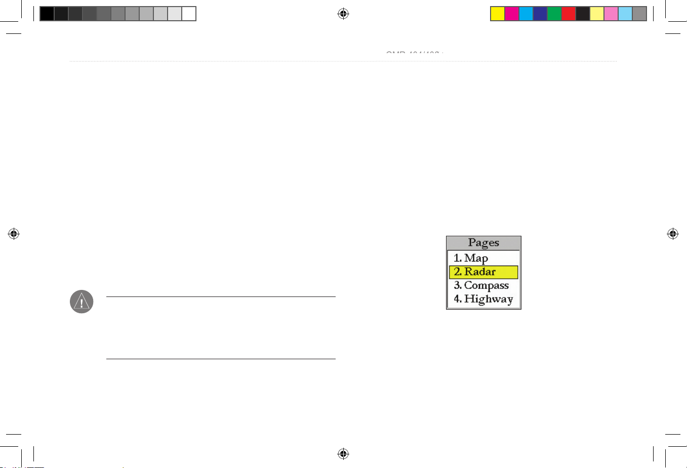
To Select the Radar Page for display:
1. Press PAGE to display the Pages list.
2. Using the Rocker, select Radar.
3. Press ENTER.
Pages List
GMR 404/406 OPERATION > RADAR OVERVIEW—THE RADAR PAGE
Prelimimary Copy—For Review Only
PRELIMINARY
PRELIMINARY
GMR 404_406 Owners Manual Preliminary Review.indd 1 3/27/2006 4:08:13 PM
Page 6
2 GMR 404/406 Owner’s Manual
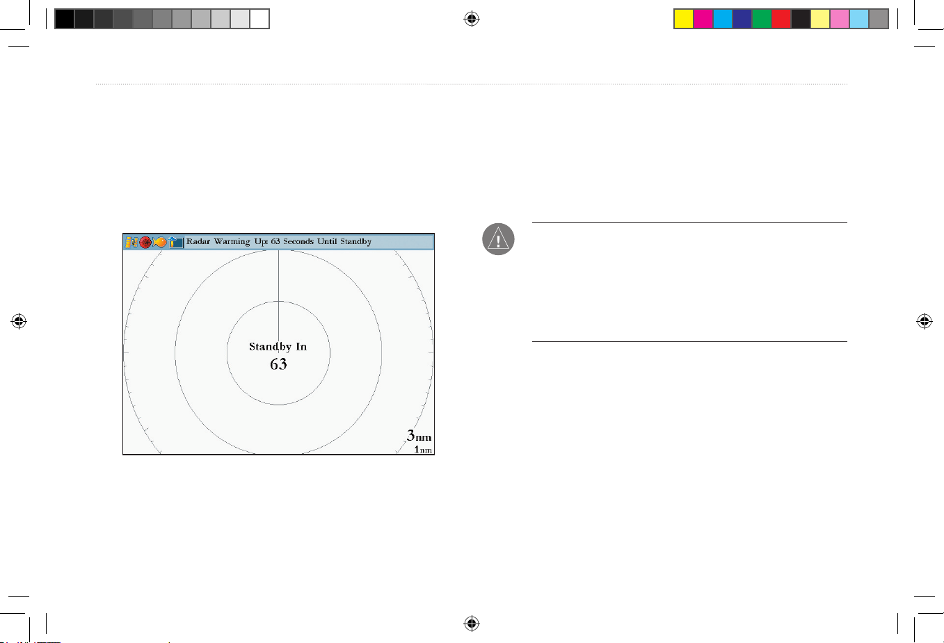
When the scanner is powered on, the Status Bar at the top of the
Radar Page, shows the message “ Radar Warming Up” with a
countdown to Standby Mode. The countdown is also displayed in
the middle of the Radar Page. When the countdown reaches zero, the
message changes to “Hold FCTN to transmit.”
As a safety feature, the scanner enters standby mode after it warms
up. This provides the operator an opportunity to verify that the area
around the scanner is clear before beginning radar transmission. It is
important to remember that the microwave energy transmitted by the
scanner can potentially be dangerous.
CAUTION: The GMR 404/406 radar transmits microwave
energy that has the potential to be harmful to humans and
animals. Before beginning radar transmission, verify that the area
around the scanner is clear. The GMR 404/406 transmits a beam
approximately 12° above and below a line extending horizontally
from the center of the scanner. Avoid looking directly at the
scanner, the eyes are the most susceptible part of the body.
When the area surrounding the scanner is clear, press and hold
FCTN. The message “Do you want to begin radar transmission?”
is displayed. Select Yes, then press ENTER. Before transmission
begins, the message “ Spinning Up” is shown while the radar antenna
reaches nominal rotation speed. When the message disappears, the
radar begins painting an image.
GMR 404/406 OPERATION >THE RADAR PAGE
Prelimimary Copy—For Review Only
PRELIMINARY
PRELIMINARY
GMR 404_406 Owners Manual Preliminary Review.indd 2 3/27/2006 4:08:13 PM
Page 7
GMR 404/406 Owner’s Manual 3
Radar Page Layout
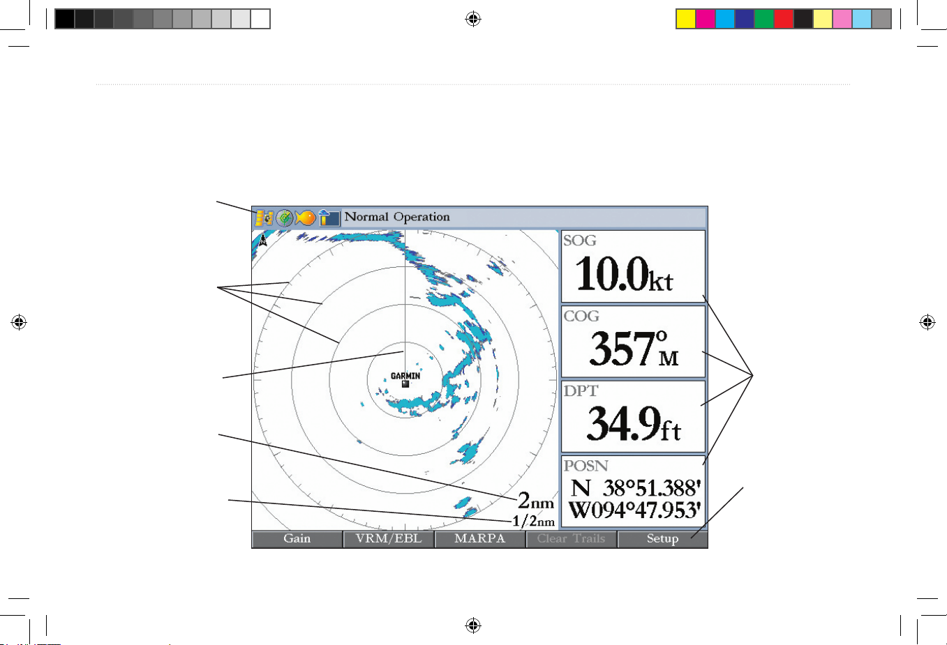
This section describes the features of the Radar Page and how its features are displayed. By default, the Radar Page displays a Status Bar along
the top, user confi gurable Digital Navigation Data down the right side, a Heading Line, and Range Rings. Soft key options that allow quick
access to radar functions and setting changes are displayed along the bottom of the page.
Status bar
Range rings
Zoom scale
Ring separation
Digital
navigation
data
Soft key options
Heading line
GMR 404/406 OPERATION > RADAR PAGE LAYOUT
Prelimimary Copy—For Review Only
PRELIMINARY
PRELIMINARY
GMR 404_406 Owners Manual Preliminary Review.indd 3 3/27/2006 4:08:14 PM
Page 8

4 GMR 404/406 Owner’s Manual
Range Rings
The Range Rings help to quickly determine the distance to a target. In
the lower-right corner of the display are two scales. The upper scale
is the current zoom scale. This scale is changed using the
RANGE
keys. The zoom scale is represented by the Range Ring with tick
marks around the circumference. The tick marks are arranged with
major tick marks at thirty-degree increments and minor tick marks
every fi ve degrees. The tick marks can help in quickly determining
the azimuth to a target. The lower scale represents the distance
between the Range Rings.
Heading Line
The Heading Line is shown from your current position along the path
of your current heading.
Digital Navigation Data
By default, the Radar Page shows one column of digital navigation
data with four data fi elds. The Radar Page can be confi gured to show
two columns of data with up to seven data fi elds each. Each data fi eld
can be confi gured to show a variety of data.
3/4 nm
1/2 nm
1/4 nm
GMR 404/406 OPERATION > RANGE RINGS—HEADING LINE—DIGITAL NAVIGATION DATA
Prelimimary Copy—For Review Only
PRELIMINARY
PRELIMINARY
GMR 404_406 Owners Manual Preliminary Review.indd 4 3/27/2006 4:08:14 PM
Page 9
GMR 404/406 Owner’s Manual 5
The Radar Confi guration Page
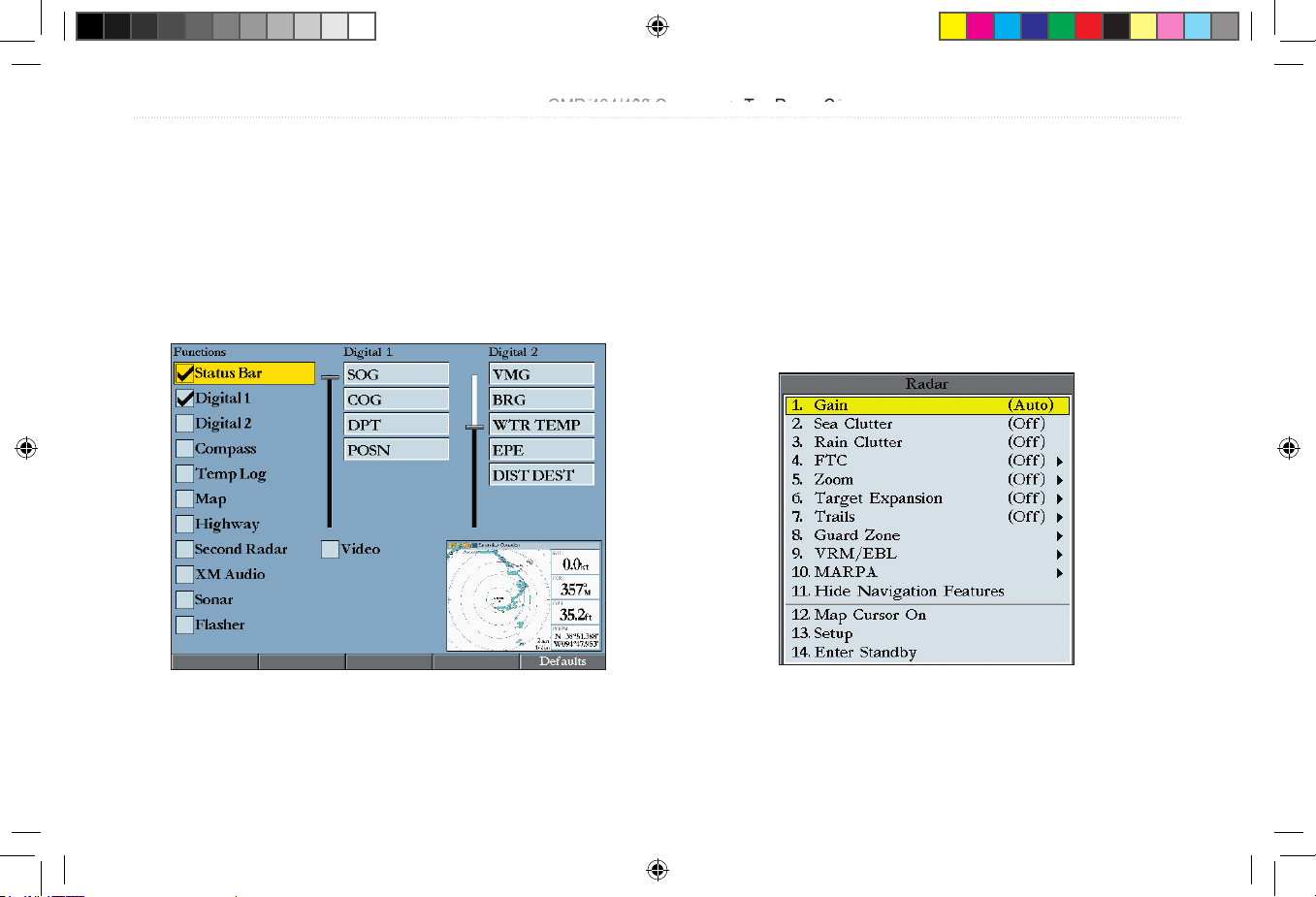
The Radar Confi guration Page is used to change the look of the Radar
Page. Please refer to the GPSMAP 3000 series owner’s manual for
information about “Confi guring the Main Pages.”
To display the Radar Confi guration Page:
Press and hold DATA\CONFIG.
The Radar Adjustment Menu
The Radar Adjustment Menu is a numbered list of options that allows
direct access to the settings and features most commonly used on the
Radar Page. There are several adjustment options available:
Gain, Sea
Clutter, Rain Clutter, FTC, Zoom, Target Expansion, Trails, Guard
Zone, VRM/EBL, MARPA, and Hide/Show Navigation Features. All
adjustments are made using the Rocker, or Data Entry keys.
GMR 404/406 OPERATION > THE RADAR CONFIGURATION PAGE—THE RADAR ADJUSTMENT MENU
Radar Confi guration Page
Radar Adjustment Menu
Prelimimary Copy—For Review Only
PRELIMINARY
PRELIMINARY
GMR 404_406 Owners Manual Preliminary Review.indd 5 3/27/2006 4:08:15 PM
Page 10
6 GMR 404/406 Owner’s Manual
GMR 404/406 OPERATION > THE RADAR ADJUSTMENT MENU
To change a Radar Adjustment Menu setting:
1. Press ADJ/MENU to display the Adjustment Menu.
2. Use the Rocker or Data Entry keys to select an option. Press
ENTER to display the adjustment for that selection.
3. Use the Rocker to change the current setting. Press ENTER
to accept the change.
Gain
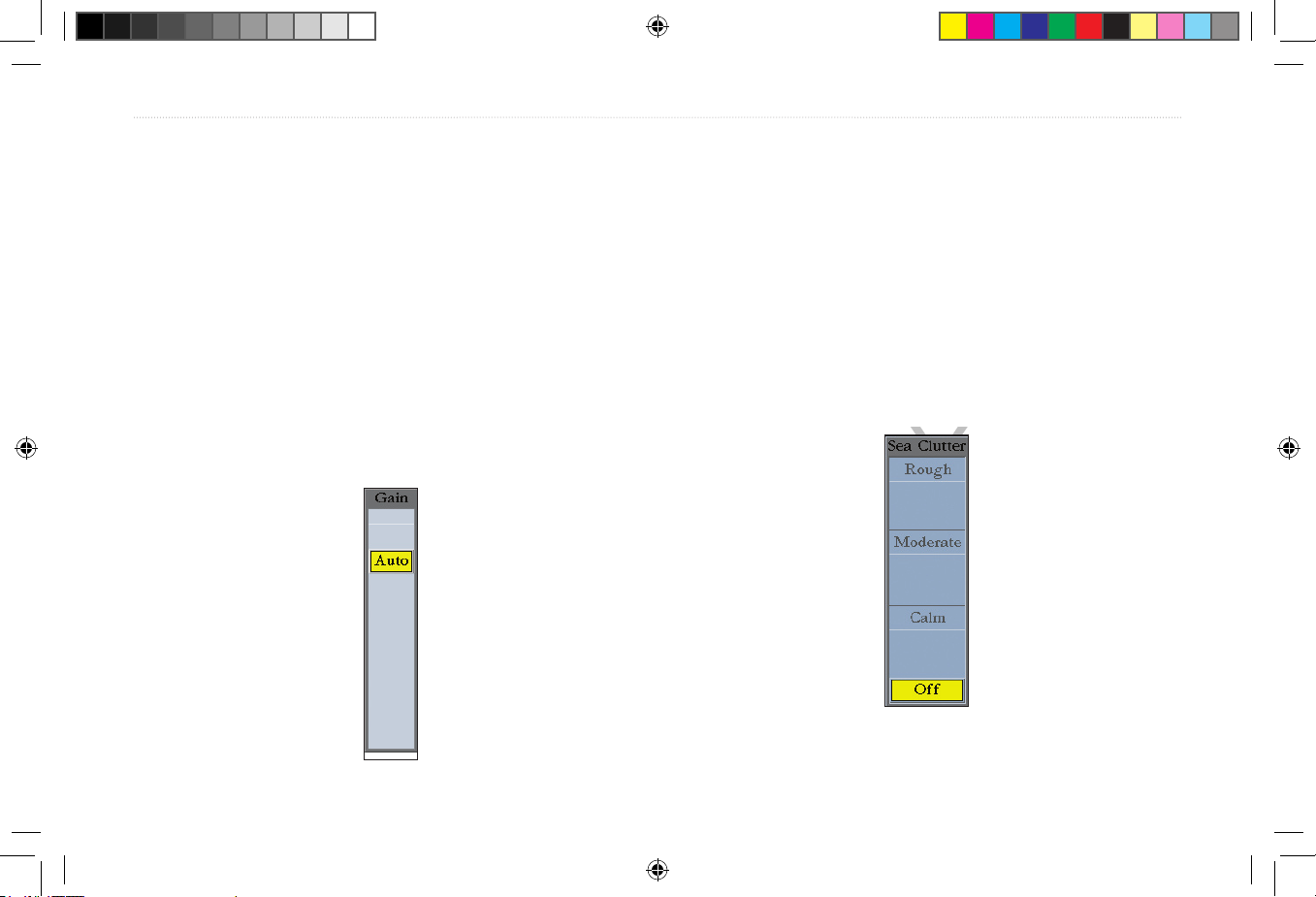
Selecting Gain displays the Gain adjustment slider. When Auto
is selected, the scanner’s gain is automatically adjusted to provide
optimal performance. Manually adjusting the gain increases or
decreases the receiver’s sensitivity. Increasing the gain may help to
show a distant target, but may also increase screen clutter.
To change the Gain setting:
1, Use the Rocker to move the slider up or down.
2. Press ENTER to accept the change.
To return the Gain setting to Auto, move the slider to the Auto
position, or press the Auto soft key.
Sea Clutter
Adjusting the Sea Clutter setting can help eliminate any unwanted
screen clutter caused by choppy sea conditions. Selecting Sea Clutter
displays the Sea Clutter adjustment slider. The slider has three preset
positions: Calm, Moderate, and Rough.
Prelimimary Copy—For Review Only
PRELIMINARY
PRELIMINARY
GMR 404_406 Owners Manual Preliminary Review.indd 6 3/27/2006 4:08:16 PM
Page 11
GMR 404/406 Owner’s Manual 7
GMR 404/406 OPERATION > THE RADAR ADJUSTMENT MENU
To change the Sea Clutter setting:
1. Use the Rocker to move the slider to a preset or other
position.
2. Press ENTER to accept the change.
The preset positions can also be selected using the soft key options.
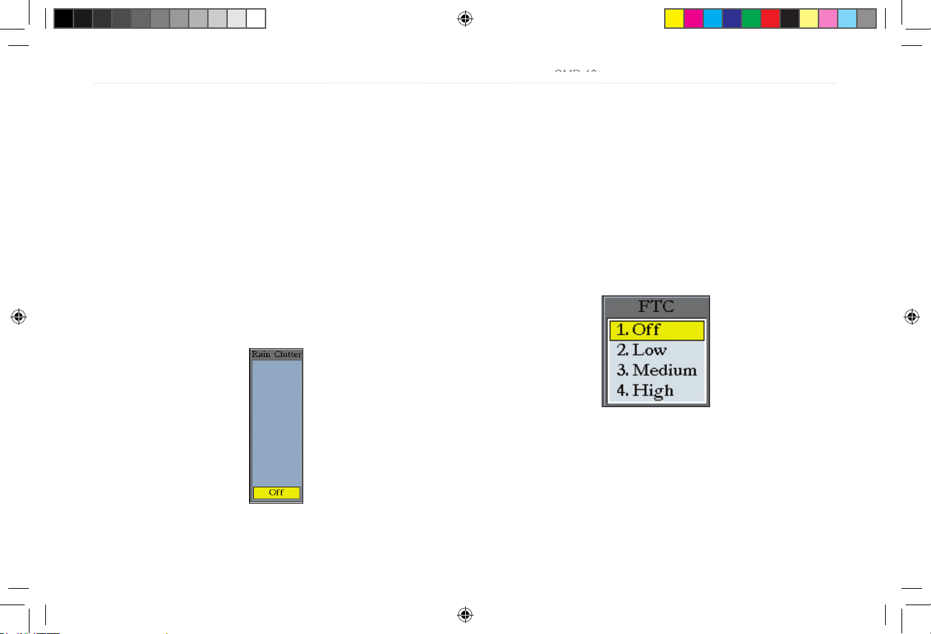
Rain Clutter
Adjusting the Rain Clutter setting can help remove screen clutter
caused by rain at close ranges. Selecting Rain Clutter displays the
Rain Clutter adjustment slider.
To change the Rain Clutter setting:
1. Use the Rocker to move the slider to the desired setting.
2. Press ENTER to accept the change.
FTC ( Fast Time Constant)
Adjusting the Fast Time Constant can help eliminate distant screen
clutter caused by rain. The Fast Time Constant has four presets: Off,
Low, Medium, and High.
To change the FTC setting:
1. Use the Rocker to select a new setting.
2. Press ENTER to accept the change.
The FTC settings can also be selected using the soft key options.
FTC Menu
Prelimimary Copy—For Review Only
PRELIMINARY
PRELIMINARY
GMR 404_406 Owners Manual Preliminary Review.indd 7 3/27/2006 4:08:17 PM
Page 12
8 GMR 404/406 Owner’s Manual
GMR 404/406 OPERATION > THE RADAR ADJUSTMENT MENU
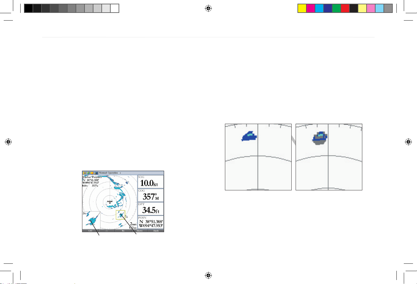
Zoom
When a Zoom level is selected, a window showing a zoomed portion of
the screen appears and a selection box is shown. The selection box can be
moved to see different areas. The Zoom setting has four presets: Off, 2x, 4x,
and Move.
To change the Zoom setting:
1. Use the Rocker to select a new setting.
2. Press ENTER to accept the change.
The Zoom settings can also be selected using the soft key options
To move the selection box:
1. Use the Rocker to move the pointer and highlight the edge of
the selection box.
2. Press ENTER to activate the Move function.
3. Use the Rocker to move the selection box to a new location.
4. Press ENTER to accept the move
Target Expansion
Target Expansion increases the size of a target. Target Expansion has
two settings, On and Off. The Target Expansion setting has no effect
at range settings of 4 nm or greater.
To turn Target Expansion On or Off:
1. Use the Rocker to highlight On or Off.
2. Press ENTER to accept the change.
Target Expansion Off Target Expansion On
zoom view selection box
Prelimimary Copy—For Review Only
PRELIMINARY
GMR 404_406 Owners Manual Preliminary Review.indd 8 3/27/2006 4:08:18 PM
PRELIMINARY
Page 13
GMR 404/406 Owner’s Manual 9
GMR 404/406 OPERATION > THE RADAR ADJUSTMENT MENU
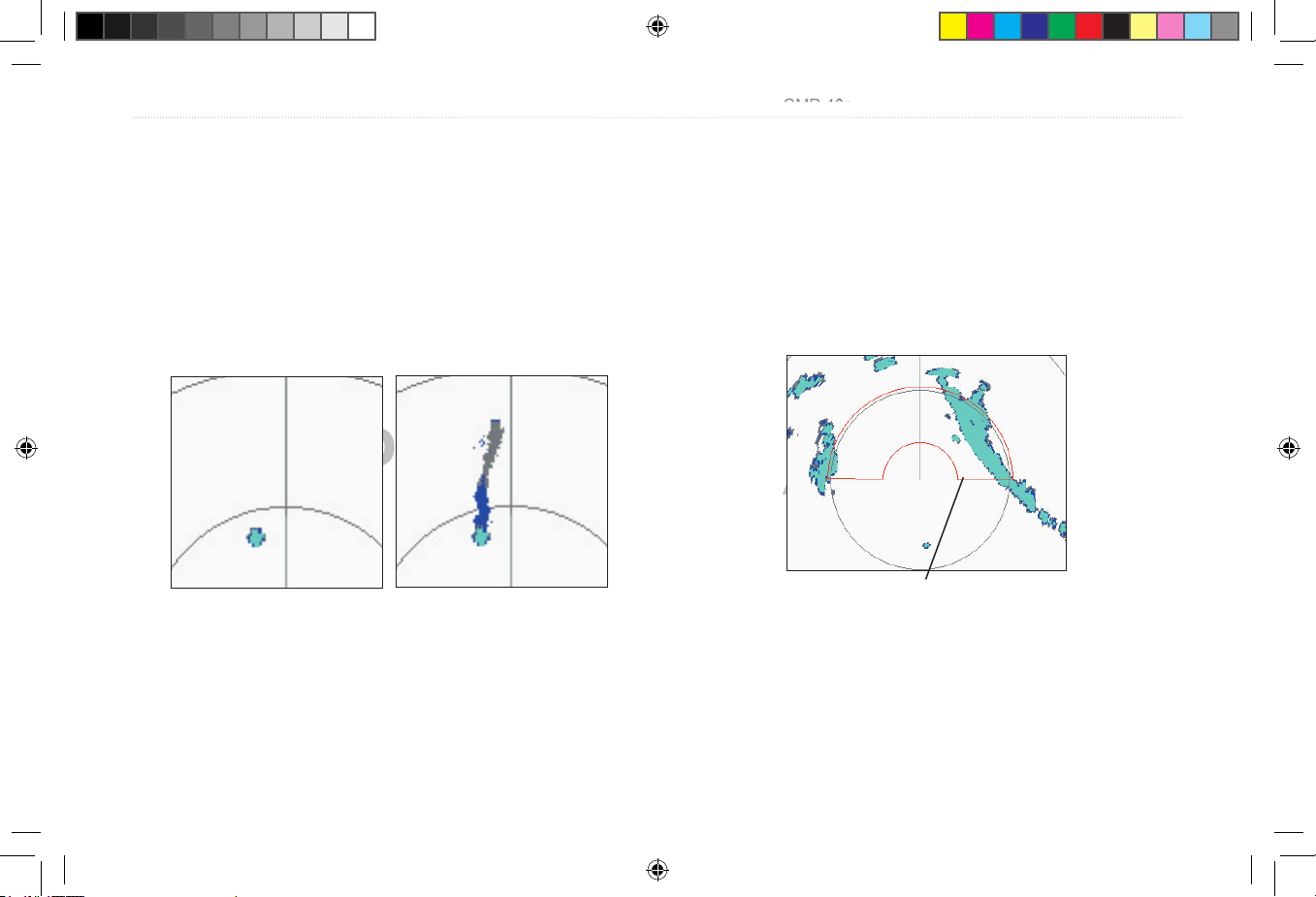
Trails
When the Trails function is on, all returns on the display leave a
history trail. The Trails setting determines the length of the history
trail. The Trails setting has four presets:
Off, Short, Medium, and
Long.
To change the Trails setting:
1. Use the Rocker to select a new setting.
2. Press ENTER to accept the change.
Trails Off Trails On (medium)
To clear the Trails, select Clear Trails on the Adjustment Menu, or
press the Clear Trails soft key.
Guard Zone
A Guard Zone is a user-defi ned area of protection. If a target enters
the defi ned Guard Zone, an alarm is sounded. Two Guard Zones can
be defi ned at any given time.
The Guard Zone Menu has two areas, “Guard Zone 1” and “Guard
Zone 2.” Each area has two settings, Show/Hide and Adjust.
Guard Zone
continued
Prelimimary Copy—For Review Only
PRELIMINARY
PRELIMINARY
GMR 404_406 Owners Manual Preliminary Review.indd 9 3/27/2006 4:08:18 PM
Page 14
10 GMR 404/406 Owner’s Manual
GMR 404/406 OPERATION > THE RADAR ADJUSTMENT MENU
To Defi ne a Guard Zone:
1. Use the Rocker to highlight Show Guard Zone 1 or 2, and
press ENTER.
2. Use the Rocker to highlight Adjust and press ENTER.
3. Using the Rocker, defi ne the area on the Radar Page.
4. Press ENTER to accept the change.
With a Guard Zone selected on the Radar Page, soft key options may
be available.
VRM/EBL
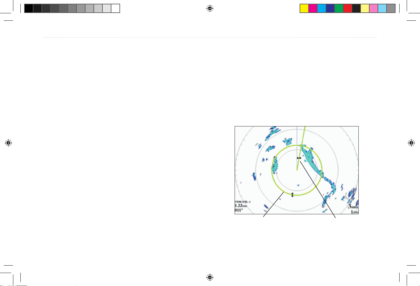
The VRM ( Variable Range Marker) and EBL ( Electronic Bearing
Line) tools measure range and bearing to a target. The center point
of the VRM can be moved, allowing measurement from one target to
another. Two V/E tools can be active at the same time.
The VRM/EBL Menu has two areas, “VRM/EBL 1” and “VRM/EBL
2.” Each area has two settings, Show/Hide and Adjust.
To activate VRM/EBL 1 or 2:
Use the Rocker to highlight Show VRM/EBL 1 or 2 and press
ENTER.
The diameter of the VRM and the angle of the EBL are adjustable.
To adjust the VRM/EBL:
1. Use the Rocker to highlight Adjust and press ENTER.
2. Press the Rocker right or left to rotate the Electronic Bearing
Line around the center point of the VRM.
3. Press the Rocker up or down to increase or decrease the size
of the Variable Range Marker.
4. Press ENTER to accept the changes.
Variable Range Marker
(VRM)
Electronic Bearing Line
(EBL)
Prelimimary Copy—For Review Only
PRELIMINARY
PRELIMINARY
GMR 404_406 Owners Manual Preliminary Review.indd 10 3/27/2006 4:08:18 PM
Page 15
GMR 404/406 Owner’s Manual 11
GMR 404/406 OPERATION > THE RADAR ADJUSTMENT MENU
To move the center location of the VRM:
1. Use the Rocker to highlight Move and press ENTER.
2. Using the Rocker, move the center point of the VRM to the
selected location.
3. Press ENTER to set the new location.
To use the VRM/EBL, expand the diameter of the VRM so that the
outer edge touches the target. Rotate the EBL until it intersects the
VRM at the target location. The measured range and bearing are
displayed in the lower left corner of the screen.
MARPA
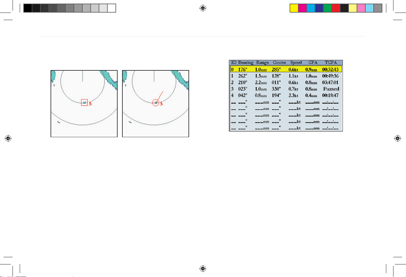
The Mini Automatic Radar Plotting Aid (MARPA) function helps
with collision avoidance. MARPA can track up to ten designated
targets. Detailed information including Bearing, Range, Course,
Speed, Closest Point of Approach, and Time to Closest Point of
Approach for each target is displayed in the MARPA list.
NOTE: The MARPA function requires the use of a heading
sensor. The heading sensor must output the NMEA sentence HDM
or HDG at format 0183, v2.30 or higher. The Gamin Marine
Network has been tested using the KVH
®
1000 heading sensor
using 6 second dampening.
MARPA relies on a Heading Sensor to provide accurate own vessel
heading information. Accurate heading data enhances MARPA’s
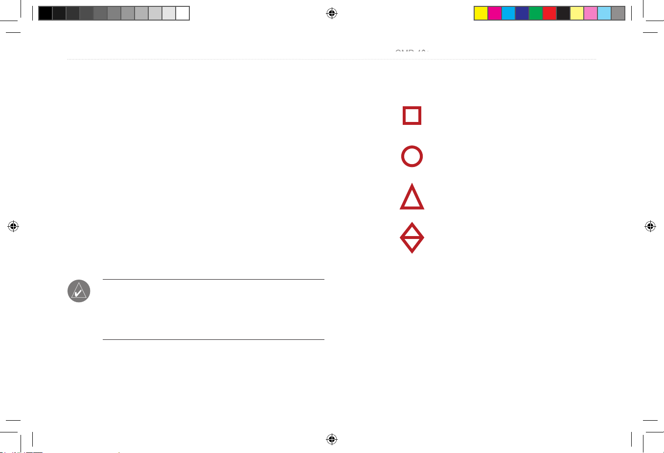
performance. Each target being tracked by MARPA is represented by
a symbol. The symbols indicate the current state of the target.
Acquiring target
Target is safe
Target is dangerous
Lost target
For each target, a number and Vector Line is displayed with the
symbol. The number is the MARPA list ID number. The Vector Line
is a visual reference of the target’s course and speed.
To designate a
MARPA target:
1. Use the Rocker to highlight Acquire Target and press
ENTER.
2. On the Radar Page, using Rocker, move the pointer to the
target, and press ENTER.
continued
Prelimimary Copy—For Review Only
PRELIMINARY
PRELIMINARY
GMR 404_406 Owners Manual Preliminary Review.indd 11 3/27/2006 4:08:19 PM
Page 16
GMR 404/406 OPERATION > THE RADAR ADJUSTMENT MENU
While a target is being designated, a box is placed around the target.
When MARPA begins tracking the target, the box is replaced with the
appropriate symbol.
Acquiring Target
Tracking Target
To display the MARPA List:
Use the Rocker to highlight MARPA List and press ENTER.
MARPA List
MARPA Setup
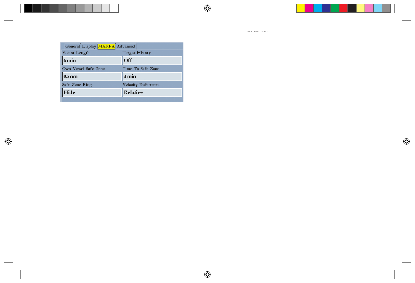
The MARPA Setup Menu contains settings for Vector Length, Target
History, Own Vessel Safe Zone, Tine To Safe Zone, Safe Ring Zone,
and Velocity Reference.
To display the
MARPA Setup Menu:
Use the Rocker to highlight MARPA Setup, and press
ENTER.
12
Prelimimary Copy—For Review Only
PRELIMINARY
PRELIMINARY
GMR 404_406 Owners Manual Preliminary Review.indd 12 3/27/2006 4:08:19 PM
Page 17
GMR 404/406 Owner’s Manual 13
GMR 404/406 OPERATION > THE RADAR ADJUSTMENT MENU
MARPA Setup Menu
To change a MARPA fi eld option:
1. Use the Rocker to highlight the desired fi eld and press
ENTER to activate the fi eld selections.
2. Use the Rocker to highlight the desired selection.
3. Press ENTER to accept the change.
Vector Length —predicts the target’s approximate position at a set
time interval. This setting determines the length of the Vector Line,
based on the time interval setting and the target’s speed. The time
interval settings range from .05 minutes to 60 minutes.
Target History—is a trail showing a targets movement. Target
History can be turned On or Off.
Own Vessel Safe Zone—is a circular area defi ned by a range setting
that is centered on your own vessel. If a target enters the defi ned area
an alarm is sounded. The Safe Zone can be set to a distance between
.01 and 2 nautical miles.
Time To Safe Zone—sounds an alarm if MARPA determines that a
target will intersect the Own Vessel Safe Zone within the defi ned time
interval. The time interval settings range from 3 to 24 minutes.
Safe Zone Ring—displays a ring on the Radar Page depicting the
Own Vessel Safe Zone.
Velocity Reference—has two settings, Absolute and Relative. This
setting determines how speed and direction are displayed on the
MARPA list. Relative calculates target speed and direction relative to
your own. Absolute displays the target’s actual speed.
Hide/Show Navigation Features
This setting hides or shows navigation features such as Waypoints, a
Bearing Line and a Course Line on the Radar Page. See page 16 for
more information on selecting the Navigation Features.
Additional Adjustment Menu Items
There are three additional items available on the Adjustment Menu:
Map Cursor On/Off, Setup, and Enter Standby/ Begin Transmitting.
Prelimimary Copy—For Review Only
PRELIMINARY
PRELIMINARY
GMR 404_406 Owners Manual Preliminary Review.indd 13 3/27/2006 4:08:20 PM
Page 18
14 GMR 404/406 Owner’s Manual
GMR 404/406 OPERATION > THE RADAR ADJUSTMENT MENU
Map Cursor On/Off
The Map Cursor On/Off setting turns the Map Page Cursor on or off
when operating in Split Screen mode or when using two chartplotters.
To turn the Map Cursor On or Off:
Use the Rocker to highlight Map Cursor On/Off and press
ENTER.
Setup
Selecting Setup displays the Radar Setup Menu. The Radar Setup
Menu contains four sub tabs: General, Display, MARPA, and
Advanced.
The General Tab
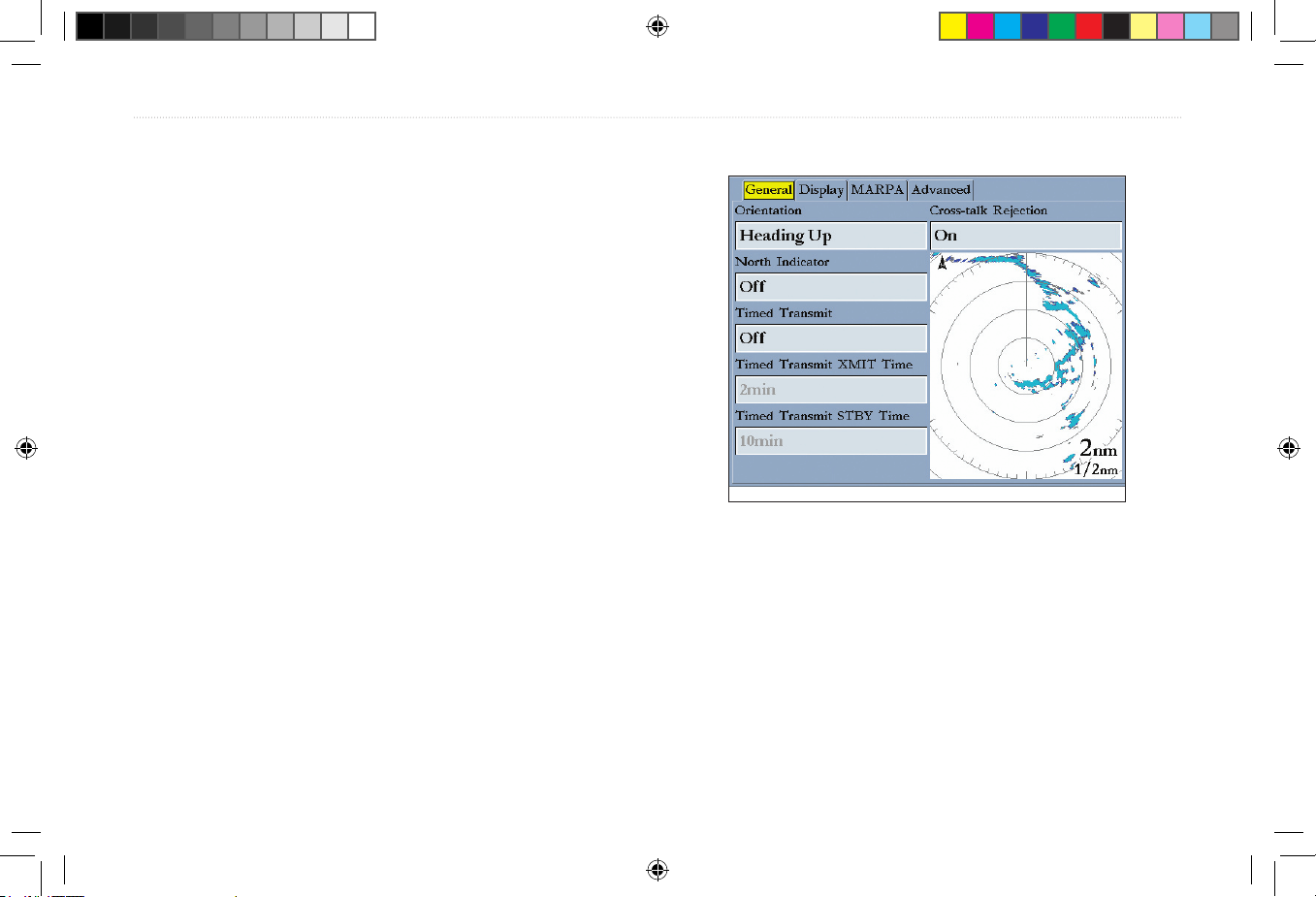
The General tab contains settings for Orientation, Cross-talk
Rejection, Front of Boat Offset, Timed Transmit, Timed Transmit
XMIT Time, and Timed Transmit STBY Time.
To change a Setup fi eld option:
1. Use the Rocker to highlight the fi eld and press ENTER to
show the fi eld selections.
2. Use the Rocker to highlight the selection.
3. Press
ENTER to accept the change.
The General Tab
Orientation—confi gures the Radar Page to display in one of three
modes: Heading Up, North Up, or Course Up.
Cross-talk Rejection—radar cross-talk may occur when two or
more radar equipped vessels are operating in proximity to one
another. Cross-talk rejection automatically fi lters out the cross-talk
interference.
Prelimimary Copy—For Review Only
PRELIMINARY
PRELIMINARY
GMR 404_406 Owners Manual Preliminary Review.indd 14 3/27/2006 4:08:21 PM
Page 19
GMR 404/406 Owner’s Manual 15
GMR 404/406 OPERATION > THE RADAR ADJUSTMENT MENU
Timed Transmit—is used to save power, likely while at anchor.
When Timed Transmit is
On, the radar refers to the settings in Timed
Transmit XMIT Time and Timed Transmit STBY Time. If Off is
selected, the Timed Transmit XMIT Time and Timed Transmit STBY
Time fi elds are inactive.
Timed Transmit XMIT Time—
determines a time interval in
minutes the radar transmits. For example, if set to 01 min, the radar
transmits for a period of one minute before referring to the Timed
Transmit STBY Time.
Timed Transmit STBY Time—
determines a time interval in minutes
that the radar is in stands by. For example, if set to 10 min, the radar
stands by for a period of ten minutes before referring to the Timed
Transmit XMIT Time. When the radar is standing by, the scanner
does not rotate or transmit; however, power is still applied to the
Magnetron, eliminating the need for a warm-up cycle.
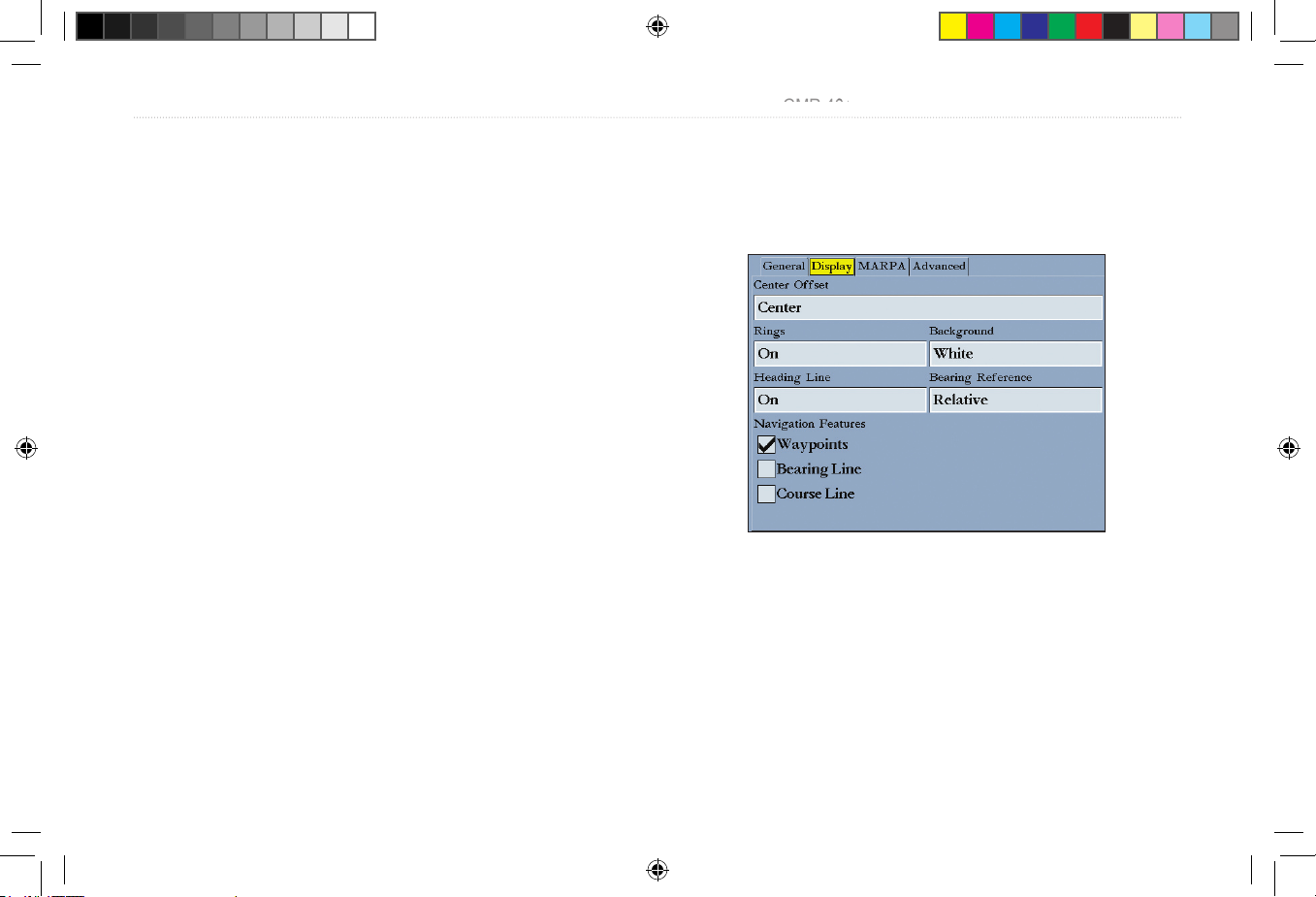
The Display Tab
The Display tab contains settings for Center Offset, Rings,
Background color, Heading Line, Bearing Reference, and Navigation
Features.
The Display Tab
Center Offset—has three settings: Center, Look Ahead, and Auto
Shift. Center places your current location in the center of the display.
Look Ahead shifts your current location toward the bottom of the
display, allowing you to view an area farther ahead. Auto Shift adjusts
your location on the display according to the current speed.
Prelimimary Copy—For Review Only
PRELIMINARY
PRELIMINARY
GMR 404_406 Owners Manual Preliminary Review.indd 15 3/27/2006 4:08:21 PM
Page 20
16 GMR 404/406 Owner’s Manual
GMR 404/406 OPERATION > THE RADAR ADJUSTMENT MENU
Rings—is used to turn the radar Range Rings On or Off.
Background—is used to select a background color for the Radar
Page. The options are Black, Blue, and White.
Heading Line—is used to turn the Heading Line On or Off.
Bearing Reference—has two settings, Absolute and Relative.
Relative calculates the bearing relative to own vessel heading.
Absolute calculates the bearing referring to North.
Navigation Features—there are three selectable Navigation
Features: Waypoints, Bearing Line, and Course Line. When selected,
that feature is displayed on the Radar Page.
•
Waypoints—displays user waypoints on the Radar Page.
•
Bearing Line—displays a bearing line on the Radar Page.
The bearing line is displayed as a line from your current
position to the active destination waypoint, similar to a
traditional lollipop.
•
Course Line—displays a course line from your starting point
to the active destination waypoint, similar to navigation on a
map.
The MARPA Tab
See “MARPA Setup” on page 12.
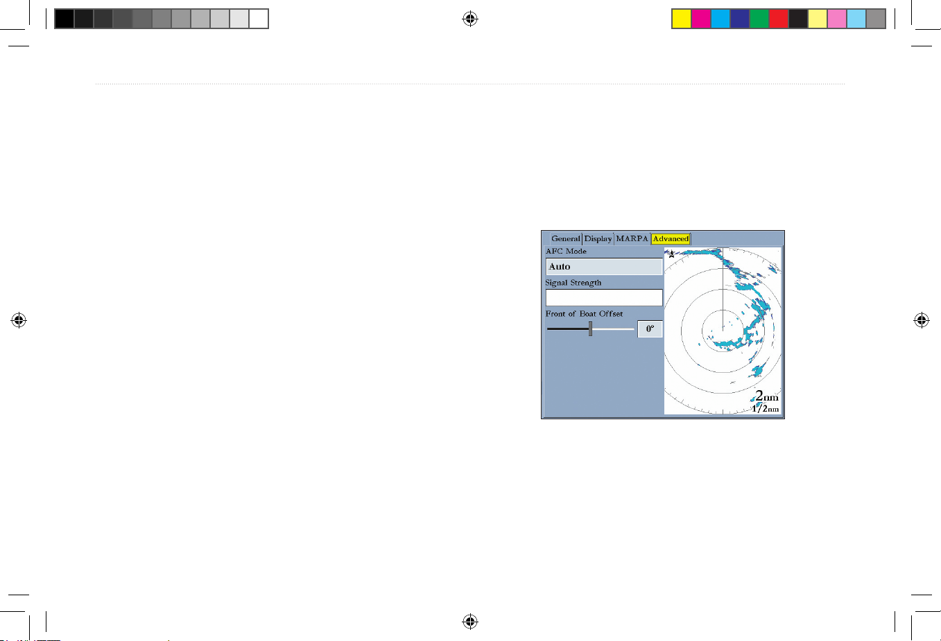
The Advanced Tab
AFC Mode—has two settings, Auto and Manual. In Auto mode the
scanner frequency is automatically adjusted for optimal performance
and is recommended.
The Advanced Tab
Prelimimary Copy—For Review Only
PRELIMINARY
PRELIMINARY
GMR 404_406 Owners Manual Preliminary Review.indd 16 3/27/2006 4:08:22 PM
Page 21
GMR 404/406 Owner’s Manual 17
To select an AFC mode:
1. Use the Rocker to highlight the AFC Mode fi eld, and press
ENTER.
2. Use the Rocker to highlight the selection, and press ENTER.
To manually adjust the scanner frequency:
1. Use the Rocker to highlight the Freq button, and press
ENTER.
2. Using the Rocker, adjust the scanner frequency up or down to
achieve the desired effect.
3. Press ENTER to accept the frequency change.
NOTE: The Signal Strength bar graph is damped and may be
slow when responding to frequency tuning changes.
Enter Standby/ Begin Transmitting
Selecting Enter Standby places the scanner into Standby mode
While in Standby mode, the scanner does not transmit, but power
remains applied to the Magnetron.
If the scanner is in Standby mode, Begin Transmitting is enabled.
Selecting Begin Transmitting removes the scanner from Standby
mode, and after “Spinning Up”, the scanner begins transmitting.
To select Enter Standby or Begin Transmitting:
Use the Rocker to highlight the Enter Standby or Begin
Transmitting, and press ENTER.
Map Page Radar Overlay
Radar information can be displayed as an overlay on the Map page.
With radar information overlaid on the map, many of the radar
options are available by pressing the ADJ/MENU key.
It is important to note that changing the “Range” of the map does not
change the scanner range. When the Map page is zoomed in or out,
the radar overlay is scaled to fi t.
To overlay radar data on the Map Page:
1. Press ADJ/MENU.
2. Use the Rocker to highlight Show Radar, and press ENTER.
To hide the Radar Overlay:
1. Press ADJ/MENU.
2. Use the Rocker to highlight Radar Options, and press
ENTER.
3. Use the Rocker to highlight Hide Radar, and press ENTER.
GMR 404/406 OPERATION > MAP PAGE RADAR OVERLAY
Prelimimary Copy—For Review Only
PRELIMINARY
PRELIMINARY
GMR 404_406 Owners Manual Preliminary Review.indd 17 3/27/2006 4:08:22 PM
Page 22
18 GMR 404/406 Owner’s Manual
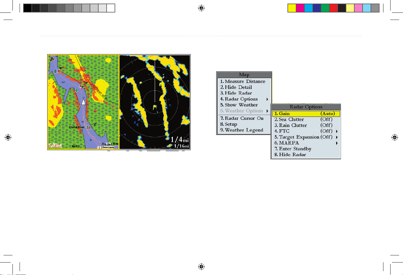
Map Page with Radar Overlay Radar Page
There are several Radar Options available on the Map Page. These
options do affect operation of the radar and the Radar Page.
To display the
Radar Options:
1. Press ADJ/MENU.
2. Use the Rocker to highlight Radar Options, and press
ENTER.
GMR 404/406 OPERATION > MAP PAGE RADAR OVERLAY
Map Page Radar Options
Prelimimary Copy—For Review Only
PRELIMINARY
PRELIMINARY
GMR 404_406 Owners Manual Preliminary Review.indd 18 3/27/2006 4:08:23 PM
Page 23
GMR 404/406 Owner’s Manual 19
APPENDIX
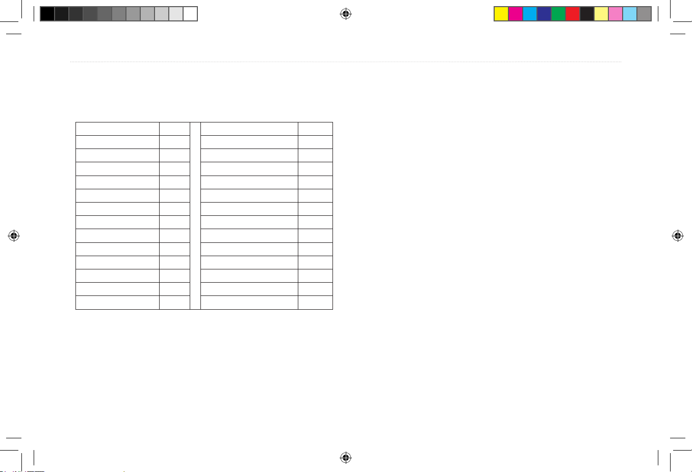
European License Requirements
Austria I Luxembourg I
Belgium G The Netherlands I
Czech Republic I Poland G
Denmark G Portugal G
Estonia * Slovakia *
Finland I Slovenia G
France G Spain *
Germany G Sweden G
Greece G United Kingdom I
Hungary * Cyprus G
Ireland * Malta *
Italy G Iceland G
Latvia I Norway I
Lithuania G Switzerland I
I —Requires an individual license for operation.
G—can be operated under a general license or license exemption.
* This product may require licensing in your country of use. Please
refer to the national radio or telecommunications offi ce or ministry.
APPENDIX > EUROPEAN LICENSE REQUIREMENTS
Prelimimary Copy—For Review Only
PRELIMINARY
PRELIMINARY
GMR 404_406 Owners Manual Preliminary Review.indd 19 3/27/2006 4:08:23 PM
Page 24
20 GMR 404/406 Owner’s Manual
Specifi cations
Unit Dimensions: 28” (710 mm) D x 8” (205 mm) H
Radar Scanner Weight:
Unit 26 lbs; cable 8.35 lbs
Range Scales (Range Rings): GMR 406—1/8 nm (1/32 nm) to 36
nm (9 nm). GMR 404—1/8 nm (1/32 nm) to 24 nm (6 nm)
Power Output: GMR 404: 2 kW, GMR 406: 4kW
Power Input Source: 10–35 VDC, 28W.
Operating Temperature Range:
-25°C to 70°C, and a relative
humidity up to 95% at 35°C
Beamwidth: Horizontal beamwidth of 3.6° nominal / vertical
beamwidth of 25° nominal.
Range: GMR 404—24 nm, GMR 406—36 nm.
Wind Velocity: Wind speed up to 100 Kts
Antenna RPMs: 24 rpm.
Range Ring Accuracy:
+/- 1 meter
Bearing Accuracy:
1°
Minimum Range: 35 meters
Range Discrimination: 30 meters
Sensitivity and Tune Controls: Gain, Sea Clutter, Rain Clutter,
Frequency Tune
Radar/Chart Synchronization:
Overlay Mode. split overlay with
standard radar presentation.
Off Center Function: Look Ahead, Auto Shift, and Manual
RF Transmit Frequency:
9410 ± 30 MHz
APPENDIX > SPECIFICATIONS
Prelimimary Copy—For Review Only
PRELIMINARY
PRELIMINARY
GMR 404_406 Owners Manual Preliminary Review.indd 20 3/27/2006 4:08:24 PM
Page 25
GMR 404/406 Owner’s Manual 21
FCC Compliance
The GMR 404/406 complies with Part 80 of the FCC rules. It has
received a grant of equipment authorization, issued under the authority
of the FCC.
This equipment generates, uses and can radiate radio frequency
energy and, if not installed and used in accordance with
the instructions, may cause harmful interference to radio
communications. However, there is no guarantee that interference
will not occur in a particular installation. If this equipment does
cause harmful interference to radio or television reception, which
can be determined by turning the equipment off and on, the user is
encouraged to try to correct the interference by one of the following
measures:
• Reorient or relocate the receiving antenna.
• Increase the separation between the equipment and the receiver.
• Connect the equipment into an outlet on a circuit different from
that to which the receiver is connected.
• Consult the dealer or an experienced radio/TV technician for
help.
Declaration of Conformity
Hereby, Garmin declares that this GMR 404/406 Marine Radar
product is in compliance with the essential requirements and other
relevant provisions of Directive 1999/5/EC.
To view the full Declaration of Conformity, see the Garmin Web site
for your Garmin product: http://www.garmin.com/products/sp310/.
Click Manuals and then select the Declaration of Conformity.
APPENDIX > FCC COMPLIANCE
Prelimimary Copy—For Review Only
PRELIMINARY
PRELIMINARY
GMR 404_406 Owners Manual Preliminary Review.indd 21 3/27/2006 4:08:24 PM
Page 26
22 GMR 404/406 Owner’s Manual
Software License Agreement
BY USING THE GMR 404/406, YOU AGREE TO BE BOUND
BY THE TERMS AND CONDITIONS OF THE FOLLOWING
SOFTWARE LICENSE AGREEMENT. PLEASE READ THIS
AGREEMENT CAREFULLY.
Garmin grants you a limited license to use the software embedded in
this device (the “Software”) in binary executable form in the normal
operation of the product. Title, ownership rights and intellectual
property rights in and to the Software remain in Garmin.
You acknowledge that the Software is the property of Garmin and
is protected under the United States of America copyright laws and
international copyright treaties. You further acknowledge that the
structure, organization and code of the Software are valuable trade
secrets of Garmin and that the Software in source code form remains
a valuable trade secret of Garmin. You agree not to decompile,
disassemble, modify, reverse assemble, reverse engineer, or reduce
to human readable form the Software or any part thereof or create
any derivative works based on the Software. You agree not to export
or re-export the Software to any country in violation of the export
control laws of the United States of America.
LIMITED WARRANTY
This Garmin product is warranted to be free from defects in materials
or workmanship for one year from the date of purchase. Within
this period, Garmin will at its sole option, repair or replace any
components that fail in normal use. Such repairs or replacement will
be made at no charge to the customer for parts or labor, provided that
the customer shall be responsible for any transportation cost. This
warranty does not cover failures due to abuse, misuse, accident or
unauthorized alteration or repairs.
THE WARRANTIES AND REMEDIES CONTAINED HEREIN
ARE EXCLUSIVE AND IN LIEU OF ALL OTHER WARRANTIES
EXPRESS OR IMPLIED OR STATUTORY, INCLUDING
ANY LIABILITY ARISING UNDER ANY WARRANTY OF
MERCHANTABILITY OR FITNESS FOR A PARTICULAR
PURPOSE, STATUTORY OR OTHERWISE. THIS WARRANTY
GIVES YOU SPECIFIC LEGAL RIGHTS, WHICH MAY VARY
FROM STATE TO STATE.
IN NO EVENT SHALL GARMIN BE LIABLE FOR ANY
INCIDENTAL, SPECIAL, INDIRECT OR CONSEQUENTIAL
DAMAGES, WHETHER RESULTING FROM THE USE, MISUSE,
OR INABILITY TO USE THIS PRODUCT OR FROM DEFECTS
IN THE PRODUCT.
APPENDIX > SOFTWARE LICENSE AGREEMENT, LIMITED WARRANTY
Prelimimary Copy—For Review Only
PRELIMINARY
PRELIMINARY
GMR 404_406 Owners Manual Preliminary Review.indd 22 3/27/2006 4:08:24 PM
Page 27
GMR 404/406 Owner’s Manual 23
Some states do not allow the exclusion of incidental or consequential
damages, so the above limitations may not apply to you.
Garmin retains the exclusive right to repair or replace the unit
or software or offer a full refund of the purchase price at its sole
discretion. SUCH REMEDY SHALL BE YOUR SOLE AND
EXCLUSIVE REMEDY FOR ANY BREACH OF WARRANTY.
To obtain warranty service, contact your local Garmin authorized
dealer. Or call Garmin Product Support at one of the numbers shown
below, for shipping instructions and an RMA tracking number. The
unit should be securely packed with the tracking number clearly
written on the outside of the package. The unit should then be sent,
freight charges prepaid, to any Garmin warranty service station. A
copy of the original sales receipt is required as the proof of purchase
for warranty repairs.
Products sold through online auctions are not eligible for rebates or
other special offers from Garmin. Online auction confi rmations are
not accepted for warranty verifi cation. To obtain warranty service,
an original or copy of the sales receipt from the original retailer is
required. Garmin will not replace missing components from any
package purchased through an online auction.
NOTE: The GMR 404/406 does not contain any user-serviceable
parts. Repairs should only be made by an authorized Garmin
service center. Unauthorized repairs or modifi cations could result
in permanent damage to the equipment and void your warranty.
Garmin International, Inc.
1200 Ease 151st Street
Olathe, Kansas 66062, U.S.A.
Phone: 913/397.8200
USA Only: 800/800.1020
FAX: 913/397.0836
Garmin (Europe) Ltd.
Unit 4, The Quadrangle, Abbey Park Industrial Estate
Romsey, S051 9DL, U.K.
Phone: 44/0870.8501241
FAX: 44/0870.8501251
Garmin Corporation
No. 68, Jangshu 2nd Road, Shijr, Taipei County, Taiwan
Tel. 886/2.2642.9199
Fax 886/2.2642.9099
APPENDIX > LIMITED WARRANTY
Prelimimary Copy—For Review Only
PRELIMINARY
PRELIMINARY
GMR 404_406 Owners Manual Preliminary Review.indd 23 3/27/2006 4:08:24 PM
Page 28
24 GMR 404/406 Owner’s Manual
APPENDIX > WARNINGS AND CAUTIONS
Failure to avoid the following potentially hazardous situations could
result in an accident or collision resulting in death or serious injury.
WARNING: The radar scanner transmits electromagnetic energy. Ensure that
the scanner has been installed according to the recommendations given in
this guide, and that all personnel are clear of the scanner before switching to
Transmit mode.
WARNING: This product, its packaging, and its components contain
chemicals known to the State of California to cause cancer, birth defects,
or reproductive harm. This Notice is being provided in accordance with
California’s Proposition 65. If you have any questions or would like additional
information, please refer to our Web site at
http://www.garmin.com/prop65.
Warning
Failure to avoid the following potentially hazardous situations may result
in injury or property damage.
Use the GMR 404/406 at your own risk. To reduce the risk of unsafe
operation, carefully review and understand all aspects of this Owner’s
Manual, and thoroughly practice operation using the simulator mode prior to
actual use. When in actual use, carefully compare indications from the GMR
404/406 to all available navigation sources, including the information from
other NAVAIDs, visual sightings, charts, etc. For safety, always resolve any
discrepancies before continuing navigation.
IT IS THE USER’S RESPONSIBILITY TO USE THIS
PRODUCT PRUDENTLY. THIS PRODUCT IS INTENDED
TO BE USED ONLY AS A NAVIGATIONAL AID AND MUST
NOT BE USED FOR ANY PURPOSE REQUIRING PRECISE
MEASUREMENT OF DIRECTION, DISTANCE, LOCATION,
OR TOPOGRAPHY.
Caution
Prelimimary Copy—For Review Only
PRELIMINARY
PRELIMINARY
GMR 404_406 Owners Manual Preliminary Review.indd 24 3/27/2006 4:08:24 PM
Page 29
GMR 404/406 Owner’s Manual 25
INDEX
Index
A
About This Manual i
Adjustment 5
Adjustment Menu 5
Advanced Tab
16
AFC Mode 16, 17
B
Background 16
Background color 15
Bearing Line 16
Bearing Reference 15, 16
Begin Transmitting
17
Begin Transmitting. 13
C
Caution 2
Center Offset 15, 16
change Sea Clutter setting 7
change the Gain 6
Clear Trails
9
Confi guration 5
Course Line 16
Cross-talk Rejection 14
D
Defi ne a Guard Zone 10
Digital Navigation Data 3, 4
Display Tab
15
E
EBL 10
Electronic Bearing Line 10
Enter Standby 13, 17
European License Requirements 19
F
Fast Time Constant 7
FCC Compliance 21
Features 3
FTC 5, 7
G
Gain 5, 6
General Tab 14
Guard Zone 5, 9
H
Heading Line 3, 4, 15, 16
Heading Sensor 11
Hide/Show Navigation Features 5
Highlight i
L
Limited Warranty 22
M
Manually Adjust the Scanner 17
Map Cursor 13
Map Cursor On/Off
14
Map Page Radar Overlay 17
MARPA
5, 11
MARPA function
11
MARPA List
12
MARPA Setup
12
MARPA Setup Menu
12
MARPA Tab
16
MARPA target
11
Mini Automatic Radar Plotting Aid 11
N
Navigation Features 5, 13, 15, 16
O
Orientation 14
Overlay 17
Overview 1
Own Vessel Safe Zone 13
R
Radar Adjustment Menu 5
Radar Confi guration 5
Radar Confi guration Page
5
Radar Options 18
Radar Overlay 17
Radar Overview 1
Radar Page 1
Radar Page Layout 3
Radar Warming Up
2
Rain Clutter 5, 7
Range Rings 3, 4
Rings 15, 16
Ring Separation 3
S
Safety feature 2
Safe Zone Ring 13
Sea Clutter 5, 6
Setup 13, 14
Signal Strength 17
Software License Agreement
22
Software update 1
soft key options 3
Specifi cations
20
Spinning Up 2
Standby Mode 2
Status Bar 2, 3
T
Target Expansion 5, 8
Target History
13
Terminology
i
Timed Transmit
15
Timed Transmit STBY Time
15
Timed Transmit XMIT Time
15
Time To Safe Zone
13
Trails
5, 9
Prelimimary Copy—For Review Only
PRELIMINARY
PRELIMINARY
GMR 404_406 Owners Manual Preliminary Review.indd 25 3/27/2006 4:08:24 PM
Page 30
26 GMR 404/406 Owner’s Manual
INDEX
V
Variable Range Marker 10
Vector Length
13
Velocity Reference
13
VRM/EBL
5, 10
W
Warming Up 2
Warning and Cautions
24
WARRANTY
22
Waypoints
16
Z
Zoom 5, 8
Zoom level 8
Zoom Scale 3
Prelimimary Copy—For Review Only
PRELIMINARY
PRELIMINARY
GMR 404_406 Owners Manual Preliminary Review.indd 26 3/27/2006 4:08:24 PM
Page 31
PRELIMINARY
Prelimimary Copy—For Review Only
PRELIMINARY
GMR 404_406 Owners Manual Preliminary Review.indd 27 3/27/2006 4:08:24 PM
Page 32
For the latest free software updates (excluding map data) throughout the life of your
Garmin products, visit the Garmin Web site at www.garmin.com.
© Copyright 2005 Garmin Ltd. or its subsidiaries
Garmin International, Inc.
1200 East 151st Street, Olathe, Kansas 66062, U.S.A.
Garmin (Europe) Ltd.
Unit 5, The Quadrangle, Abbey Park Industrial Estate, Romsey, SO51 9DL, U.K.
Garmin Corporation
No. 68, Jangshu 2nd Road, Shijr, Taipei County, Taiwan
www.garmin.com
Part Number 190-00665-00 Rev.
A
Prelimimary Copy—For Review Only
PRELIMINARY
PRELIMINARY
GMR 404_406 Owners Manual Preliminary Review.indd 28 3/27/2006 4:08:25 PM
 Loading...