

Page 1

GTN 725/750
TSO Installation Manual
GTN 725 and GTN 750
190-01007-02 TBD 2010 Rev. A
Page 2

Page 3
©Copyright 2010
Garmin Ltd. or its subsidiaries
All Rights Reserved
Except as expressly provided herein, no part of this manual may be reproduced, copied, transmitted,
disseminated, downloaded or stored in any storage medium, for any purpose without the express prior
written consent of Garmin. Garmin hereby grants permission to download a single copy of this manual
and of any revision to this manual onto a hard drive or other electronic storage medium to be viewed and
to print one copy of this manual or of any revision hereto, provided that such electronic or printed copy of
this manual or revision must contain the complete text of this copyright notice and provided further that
any unauthorized commercial distribution of this manual or any revision hereto is strictly prohibited.
SkyWatch® and Stormscope® are registered trademarks of L-3 Communications. XM® is a registered
trademark of XM Satellite Radio, Inc.
At Garmin, we value your opinion. For comments about this guide, please e-mail:
[email protected].
Garmin International, Inc.
1200 E. 151st Street
Olathe, KS 66062 USA
Telephone: 913-397-8200
Aviation Dealer Technical Support Line (Toll Free): (888) 606-5482
Web Site Address: www.garmin.com
Garmin (Europe) Ltd.
Liberty House
Bull Copse Road
Hounsdown Business Park
Southampton, SO40 9RB, UK
Telephone: 44 (0) 8708501243
RECORD OF REVISIONS
Revision Revision Date Description
A
Initial Release
GTN 725/750 TSO Installation Manual Page A
190-01007-02 Rev. A
Page 4
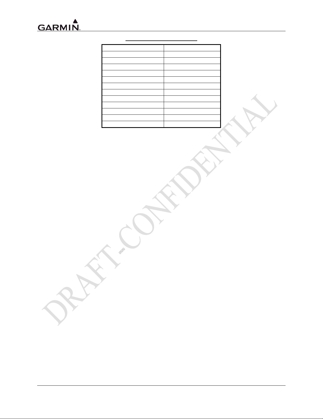
DOCUMENT PAGINATION
Section Pagination
Table of Contents i - viii
Section 1 1-1 through 1-14
Section 2 2-1 through 2-12
Section 3 3-1 through 3-10
Section 4 4-1 through 4-28
Section 5 5-1 through 5-38
Section 6 6-1 through 6-2
Section 7 7-1 through 7-2
Appendix A A-1 through A-2
Appendix B B-1 through B-10
Appendix C C-1 through C-6
Appendix D D-1 through D-40
Page B GTN 725/750 TSO Installation Manual
Rev. A 190-01007-02
Page 5

This manual is applicable for units with main software version 2.00 or later.
INFORMATION SUBJECT TO EXPORT CONTROL LAWS
This document may contain information which is subject to the Export Administration Regulations
("EAR") issued by the United States Department of Commerce (15 CFR, Chapter VII, Subchapter C) and
which may not be exported, released, or disclosed to foreign nationals inside or outside of the United
States without first obtaining an export license. A violation of the EAR may be subject to a penalty of up
to 10 years imprisonment and a fine of up to $1,000,000 under Section 2410 of the Export Administration
Act of 1979. Include this notice with any reproduced portion of this document.
WARNING
This product, its packaging, and its components contain chemicals known to the State of
California to cause cancer, birth defects, or reproductive harm. This notice is being
provided in accordance with California's Proposition 65. If you have any questions or
would like additional information, please refer to our web site at
www.garmin.com/prop65.
Perchlorate Material – special handling may apply, See
www.dtsc.ca.gov./hazardouswaste/perchlorate
.
WARNING
This product contains a Lithium battery that must be recycled or disposed of properly.
Battery replacement and removal must be performed by professional services.
GTN 725/750 TSO Installation Manual Page i
190-01007-02 Rev. A
Page 6

GENERAL DESCRIPTION ............................................................................................................1-1
1.
1.1 Introduction ..............................................................................................................................1-1
1.2 Equipment Description.............................................................................................................1-1
1.3 Technical Specifications...........................................................................................................1-2
1.3.1 Physical Characteristics........................................................................................................1-2
1.3.2 General Specifications..........................................................................................................1-2
1.3.3 GPS Specifications...............................................................................................................1-3
1.3.4 COM Specifications (GTN 750 Only) .................................................................................1-4
1.3.5 VOR Specifications (GTN 750 Only)..................................................................................1-5
1.3.6 LOC Specifications (GTN 750 Only) ..................................................................................1-5
1.3.7 Glideslope Specifications (GTN 750 Only) .........................................................................1-6
1.3.8 GPS Antenna Requirements.................................................................................................1-7
1.4 License Requirements...............................................................................................................1-8
1.5 Regulatory Compliance ............................................................................................................1-9
1.5.1 TSO Authorization and Advisory Circular References........................................................1-9
1.5.2 TSO Deviations..................................................................................................................1-11
1.5.3 FCC Grant of Equipment Authorization ............................................................................1-11
1.6 Database Options and Updates ...............................................................................................1-12
1.6.1 Navigation Database ..........................................................................................................1-12
1.6.2 TAWS/Terrain Database ....................................................................................................1-12
1.7 Fault Detection and Exclusion (FDE) ....................................................................................1-12
1.8 Limited Warranty ...................................................................................................................1-13
2. INSTALLATION OVERVIEW ......................................................................................................2-1
2.1 Introduction ..............................................................................................................................2-1
2.2 Minimum System Configuration ..............................................................................................2-1
2.2.1 VFR Installation ...................................................................................................................2-1
2.2.2 IFR GPS Installation ............................................................................................................2-1
2.2.3 IFR VOR/LOC/GLIDESLOPE Installation.........................................................................2-2
2.3 External Sensors .......................................................................................................................2-2
2.3.1 Multiple Uncorrected Pressure Altitude Sources .................................................................2-2
2.3.2 Multiple Baro-Corrected Altitude Sources...........................................................................2-3
2.3.3 Multiple Heading Sources....................................................................................................2-3
2.3.4 Multiple Indicated Airspeed Sources ...................................................................................2-4
2.3.5 Multiple True Airspeed Sources ..........................................................................................2-4
2.3.6 Multiple VLOC Course Select Sources ...............................................................................2-4
2.3.7 GPS Course Select Sources..................................................................................................2-5
2.3.8 Total Air Temperature Sources ............................................................................................2-5
2.3.9 Static Air Temperature Sources ...........................................................................................2-5
2.3.10 Joystick Waypoint Data .......................................................................................................2-6
2.4 Antenna Considerations............................................................................................................2-7
2.4.1 GPS Antenna Location.........................................................................................................2-7
2.4.2 COM Antenna Location.......................................................................................................2-8
2.4.3 VOR/LOC Antenna Location.............................................................................................2-10
2.4.4 Glideslope Antenna Location.............................................................................................2-10
2.4.5 Electrical Bonding..............................................................................................................2-10
2.4.6 Interference of GPS............................................................................................................2-10
2.5 Mounting Considerations .......................................................................................................2-11
2.6 Cabling and Wiring Considerations .......................................................................................2-11
Page ii GTN 725/750 TSO Installation Manual
Rev. A 190-01007-02
Page 7

Air Circulation and Cooling ...................................................................................................2-11
2.7
2.8 Compass Safe Distance ..........................................................................................................2-11
3. INSTALLATION PROCEDURES..................................................................................................3-1
3.1 Unit and Accessories ................................................................................................................3-1
3.2 Optional Accessories ................................................................................................................3-2
3.2.1 GPS Antenna Options ..........................................................................................................3-2
3.3 Database Options......................................................................................................................3-3
3.4 Miscellaneous Options .............................................................................................................3-3
3.5 Optional Reference Material ....................................................................................................3-3
3.6 Installation Materials Required but Not Provided....................................................................3-4
3.6.1 Optional Accessories Not Supplied......................................................................................3-4
3.6.2 Materials Required But Not Supplied (New Installations Only)..........................................3-4
3.7 Special Tools Required.............................................................................................................3-4
3.8 Cable Installation......................................................................................................................3-5
3.9 Equipment Mounting................................................................................................................3-7
3.9.1 Rack Installation...................................................................................................................3-7
3.9.2 GTN Unit Insertion and Removal ........................................................................................3-7
3.9.3 Unit Replacement.................................................................................................................3-7
3.10 Antenna Installation and Connections......................................................................................3-8
3.10.1 GPS Antenna........................................................................................................................3-8
3.10.2 COM Antenna ......................................................................................................................3-9
3.10.3 NAV Antenna.......................................................................................................................3-9
4. SYSTEM INTERCONNECTS ........................................................................................................4-1
4.1 Pin Function List ......................................................................................................................4-1
4.1.1 P1001 Main Connector – Main Board .................................................................................4-1
4.1.2 P1002 Connector..................................................................................................................4-3
4.1.3 P1003 COM Connector........................................................................................................4-4
4.1.4 P1004 NAV Connector ........................................................................................................4-5
4.2 I/O Board ..................................................................................................................................4-7
4.2.1 P1005 Connector..................................................................................................................4-7
4.3 Power, Lighting, And Antennas ...............................................................................................4-9
4.3.1 Power....................................................................................................................................4-9
4.3.2 Lighting Bus.........................................................................................................................4-9
4.3.3 Antennas...............................................................................................................................4-9
4.3.4 Serial Data..........................................................................................................................4-10
4.3.5 Ethernet (HSDB)................................................................................................................4-15
4.3.6 Main Audio Output ............................................................................................................4-15
4.3.7 Main Indicator....................................................................................................................4-16
4.3.8 OBS....................................................................................................................................4-17
4.3.9 Discrete Inputs ...................................................................................................................4-17
4.3.10 Discrete Outputs.................................................................................................................4-19
4.3.11 Heading Synchro................................................................................................................4-21
4.3.12 Composite Video (function not currently implemented) ...................................................4-22
4.3.13 COM Audio (GTN 750 only).............................................................................................4-23
4.3.14 COM Discrete Inputs .........................................................................................................4-24
4.3.15 VOR/ILS Indicator (GTN 750 only)..................................................................................4-25
4.3.16 RMI/OBI (GTN 750 only) .................................................................................................4-27
4.3.17 DME Tuning (GTN 750 only) ...........................................................................................4-28
GTN 725/750 TSO Installation Manual Page iii
190-01007-02 Rev. A
Page 8

5.
POST INSTALLATION CONFIGURATION AND CHECKOUT PROCEDURES .....................5-1
5.1 System Configuration Overview ..............................................................................................5-1
5.2 Mounting, Wiring, and Power Checks .....................................................................................5-1
5.3 Connector Engagement Check .................................................................................................5-2
5.4 Configuration Mode Operations...............................................................................................5-2
5.4.1 Main ARINC 429 Config Page ............................................................................................5-3
5.4.2 Main RS-232 Config Page ...................................................................................................5-6
5.4.3 HSDB (Ethernet) Configuration Page..................................................................................5-8
5.4.4 Interface Equipment Page ....................................................................................................5-8
5.4.5 Main CDI Indicator (Analog) Configuration Page...............................................................5-9
5.4.6 Lighting Configuration Page..............................................................................................5-10
5.4.7 Audio Configuration Page..................................................................................................5-12
5.4.8 Traffic Configuration Page.................................................................................................5-13
5.4.9 Main System Configuration Page ......................................................................................5-13
5.4.10 COM Configuration Page (GTN 750 Only)......................................................................5-14
5.4.11 VOR/LOC/GS Configuration Page....................................................................................5-15
5.5 Ground Checks (Configuration Mode)...................................................................................5-17
5.5.1 Main Indicator Check (Analog Only) ................................................................................5-17
5.5.2 VOR/ILS Indicator (Analog) .............................................................................................5-17
5.5.3 Discrete Inputs Checkout ...................................................................................................5-17
5.5.4 Discrete Outputs Checkout.................................................................................................5-18
5.5.5 HSDB Provisional Wiring Checkout .................................................................................5-18
5.5.6 TAWS Audio Check (For Units with TAWS Only) ..........................................................5-19
5.5.7 GAD 42 Interface Check....................................................................................................5-20
5.5.8 Lighting Bus Interface Check ............................................................................................5-20
5.6 Ground Checks (Normal Mode) .............................................................................................5-21
5.6.1 Display of Self-Test Data...................................................................................................5-21
5.6.2 Signal Acquisition Check...................................................................................................5-22
5.6.3 VHF COM Interference Check ..........................................................................................5-22
5.6.4 VHF NAV Checkout (GTN 750 Only) ..............................................................................5-24
5.6.5 VHF COM Checkout (GTN 750 Only)..............................................................................5-24
5.6.6 TAWS System Check (For Units with TAWS Only) ........................................................5-24
5.6.7 Altitude Encoder or Air Data Computer Check .................................................................5-25
5.6.8 AHRS/IRU Interface Check...............................................................................................5-25
5.6.9 Interface Checkout .............................................................................................................5-26
5.6.10 Magnetic Compass Check..................................................................................................5-31
5.7 Flight Checks..........................................................................................................................5-32
5.7.1 GPS Flight Check............................................................................................................... 5-32
5.7.2 VHF COM Flight Check (GTN 750) .................................................................................5-32
5.7.3 VOR Flight Check (GTN 750)...........................................................................................5-32
5.7.4 ILS Flight Check (GTN 750) .............................................................................................5-33
5.7.5 Autopilot Flight Check.......................................................................................................5-33
5.7.6 TAWS Audio Flight Check (TAWS-equipped Units Only) ..............................................5-33
5.8 Database Check ......................................................................................................................5-33
5.9 Data Card Replacement .......................................................................................................... 5-34
5.10 Software Loading ...................................................................................................................5-34
5.11 System Setup ..........................................................................................................................5-34
5.12 Documentation Checks...........................................................................................................5-34
Page iv GTN 725/750 TSO Installation Manual
Rev. A 190-01007-02
Page 9

Airplane Flight Manual Supplement ..................................................................................5-34
5.12.1
5.12.2 Instructions for Continued Airworthiness (ICAW)............................................................5-34
5.13 Configuration and Checkout Log ...........................................................................................5-35
6. LIMITATIONS................................................................................................................................6-1
6.1 Operations.................................................................................................................................6-1
6.2 Installation ................................................................................................................................6-1
6.2.1 GPS Antenna........................................................................................................................6-1
6.3 Aircraft Radio Station License .................................................................................................6-1
7. PERIODIC MAINTENANCE .........................................................................................................7-1
7.1 Equipment Calibration..............................................................................................................7-1
7.2 VOR Checks.............................................................................................................................7-1
7.3 Cleaning....................................................................................................................................7-1
7.4 Battery Replacement.................................................................................................................7-1
Appendix A ENVIRONMENTAL QUALIFICATION FORM..........................................................A-1
Appendix B GTN DATA FORMAT ..................................................................................................B-1
B.1 RS-232 Aviation Data Format................................................................................................. B-1
B.1.1 Electrical Interface .............................................................................................................. B-1
B.1.2 General Output Format ....................................................................................................... B-1
B.1.3 Output Sentence Type 1 ...................................................................................................... B-1
B.1.4 Output Sentence Type 2 ...................................................................................................... B-3
B.2 GTN RS-232 Fuel/Air Data Input Format............................................................................... B-5
B.2.1 Electrical Interface .............................................................................................................. B-5
B.2.2 Shadin Altitude Sentence .................................................................................................... B-5
B.2.3 Icarus Altitude Sentence...................................................................................................... B-5
B.2.4 Shadin Fuel Flow Sentence................................................................................................. B-6
B.2.5 ARNAV/EI Fuel Flow Sentence ......................................................................................... B-6
B.2.6 Shadin Fuel/Air Data Computer Sentence ..........................................................................B-7
Appendix C MECHANICAL DRAWINGS .......................................................................................C-1
C.1 Drawing List............................................................................................................................C-1
Appendix D INTERCONNECT DIAGRAMS....................................................................................D-1
D.1 Drawing List............................................................................................................................D-1
GTN 725/750 TSO Installation Manual Page v
190-01007-02 Rev. A
Page 10

LIST OF FIGURES
Figure 2-1. GPS Antenna Installation Considerations ..............................................................................2-9
Figure 3-1. Coaxial Cable Installation ......................................................................................................3-5
Figure 5-1. Configuration Mode Home Page............................................................................................5-2
Figure 5-2. Main ARINC 429 Configuration Page...................................................................................5-3
Figure 5-3. Main GTN Setup Page ...........................................................................................................5-3
Figure 5-4. Main RS-232 Configuration Page..........................................................................................5-6
Figure 5-5. HSDB Ethernet Port Configuration Page...............................................................................5-8
Figure 5-6. Main CDI Configuration Page ...............................................................................................5-9
Figure 5-7. Main Lighting Configuration Page ......................................................................................5-10
Figure 5-8. Photocell Configuration Page...............................................................................................5-11
Figure 5-9. Lighting Bus Configuration Page..........................................................................................5-12
Figure 5-10. Audio Configuration Page..................................................................................................5-12
Figure 5-11. COM Configuration Page...................................................................................................5-14
Figure 5-12. Traffic Configuration Page.................................................................................................5-13
Figure 5-13. Miscellaneous Configuration Page.....................................................................................5-13
Figure 5-14. Measurement of GPS Antenna Vertical Offset ..................................................................5-14
Figure 5-15. VOR/LOC/GS Configuration Page....................................................................................5-15
Figure 5-16. GTN Diagnostics Page.......................................................................................................5-17
Figure 5-17. HSDB Diagnostics Page.....................................................................................................5-18
Figure 5-18. GTN Audio Configuration Page ........................................................................................5-19
Figure 5-19. GAD 42 Configuration Page..............................................................................................5-20
Figure 5-20. Lighting Bus Configuration Page.......................................................................................5-20
Figure 5-21. Map Menu Page .................................................................................................................5-25
Figure C-1. GTN Mounting Rack Dimensions........................................................................................ C-3
Figure C-2. GTN Mounting Rack Installation .........................................................................................C-4
Figure C-3. GTN Mounting Rack Assembly ...........................................................................................C-5
Figure C-4. GTN Recommended Panel Cutout Dimensions ...................................................................C-6
Figure D-1. GTN System Interface Diagram........................................................................................... D-3
Figure D-2. GTN 750 Typical Installation...............................................................................................D-4
Figure D-3. GTN 725 Typical Installation...............................................................................................D-6
Figure D-4. GTN Power Lighting Configuration Interconnect ...............................................................D-8
Figure D-5. GTN – Antenna Interconnect ............................................................................................. D-10
Figure D-6. GTN - Main Indicator Interconnect....................................................................................D-13
Figure D-7. GTN - Autopilot Interconnect ............................................................................................D-14
Figure D-8. GTN - Traffic Interconnect ................................................................................................D-15
Figure D-9. GTN - Transponder Interconnect ....................................................................................... D-16
Figure D-10. Dual GTN to Single GDU Interconnect ........................................................................... D-17
Figure D-11. GTN - GDU/AHRS Interconnect ..................................................................................... D-18
Figure D-12. GTN - ARINC 429 EFIS Interconnect.............................................................................D-19
Figure D-13. GTN - GDL 69/69A Interconnect .................................................................................... D-21
Figure D-14. Audio Panel Interconnect .................................................................................................D-22
Figure D-15. Air Data/IRU/AHRS RS-232 Interconnect ......................................................................D-24
Figure D-16. Air Data/IRU/AHRS ARINC 429 Interconnect ...............................................................D-26
Figure D-17. GAD 42 Interconnect .......................................................................................................D-27
Figure D-18. VOR/ILS Indicator Interconnect ......................................................................................D-28
Figure D-19. RMI OBI Interconnect...................................................................................................... D-29
Figure D-20. GTN – WX-500 Interconnect...........................................................................................D-30
Figure D-21. GTN 750 - DME Interconnect.......................................................................................... D-31
Figure D-22. GTN 750 – Remote DME Interconnect............................................................................D-32
Figure D-23. Parallel 2 of 5 DME Tuning............................................................................................. D-33
Figure D-24. Parallel Slip Code DME Tuning Interconnect..................................................................D-34
Page vi GTN 725/750 TSO Installation Manual
Rev. A 190-01007-02
Page 11

Figure D-25. Heading Synchro Interconnect .........................................................................................D-35
Figure D-26. GPS Annunciator Interconnect.........................................................................................D-36
Figure D-27. NAV Source Select Annunciator Interconnect.................................................................D-37
Figure D-28. TAWS Interconnect..........................................................................................................D-38
Figure D-29. Switches Interconnect....................................................................................................... D-39
Table 1-1. GTN Units ...............................................................................................................................1-1
Table 1-2. GTN Current Specifications ....................................................................................................1-6
Table 1-3. Approved GPS Antennas.........................................................................................................1-7
Table 1-4. TSO Authorization ..................................................................................................................1-9
Table 1-5. Main Software Part Number and Version .............................................................................1-10
Table 1-6. GPS/WAAS Software Part Number and Version..................................................................1-10
Table 3-1. Catalog Part Numbers..............................................................................................................3-1
Table 3-2. Standard Kit Accessories.........................................................................................................3-1
Table 3-3. Recommended Crimp Tools (or Equivalent)...........................................................................3-4
Table 3-4. Socket Contact Part Numbers..................................................................................................3-6
Table 5-1. GTN Post-Installation Checkout Log ....................................................................................5-35
LIST OF TABLES
Table B-1. Type 1 Output Sentence Format ............................................................................................ B-2
Table B-2. Type 2 Output Sentence Format ............................................................................................ B-4
GTN 725/750 TSO Installation Manual Page vii
190-01007-02 Rev. A
Page 12
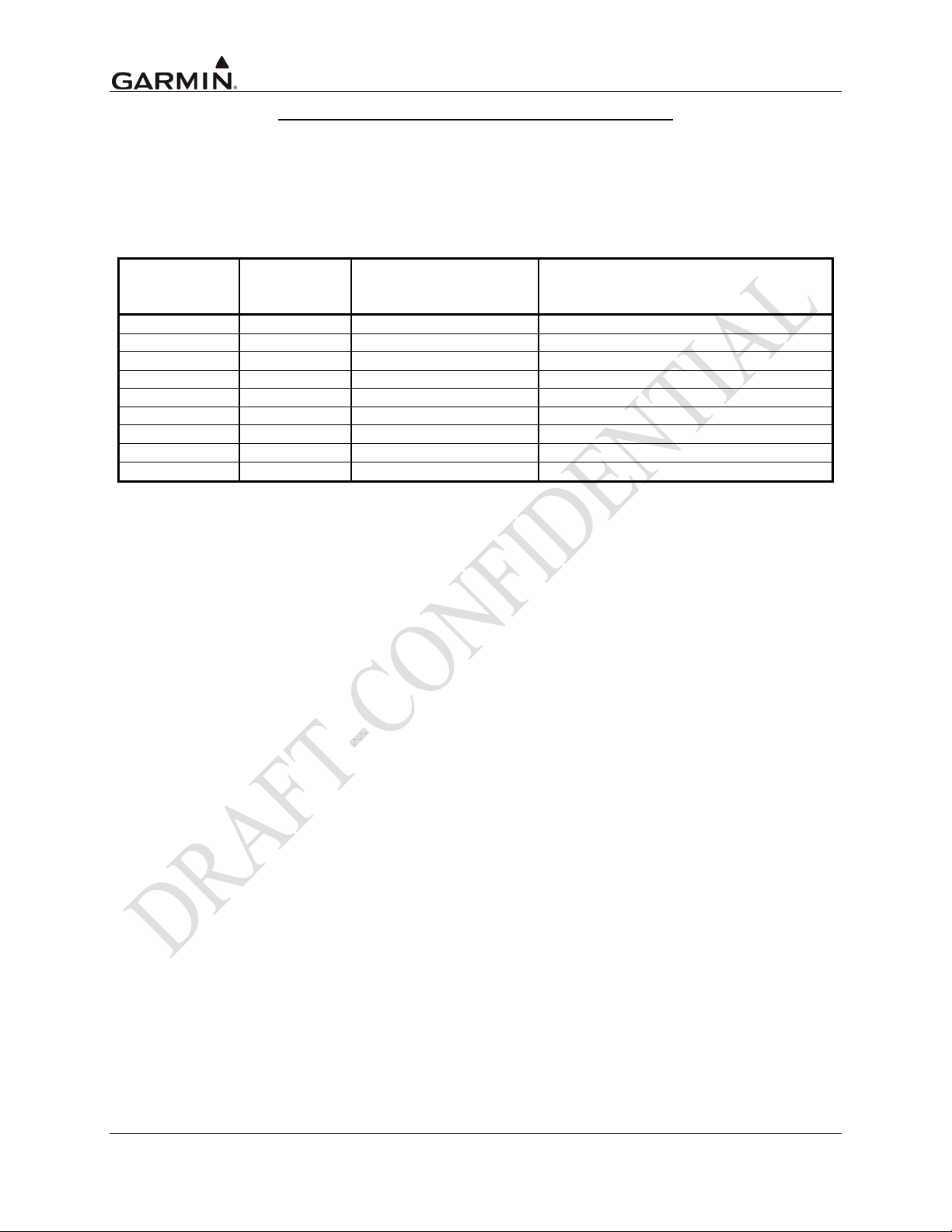
GTN 725/750 HARDWARE MOD LEVEL HISTORY
The following table identifies hardware modification (Mod) Levels for the GTN 725 and GTN 750. Mod
Levels are listed with the associated service bulletin number, service bulletin date, and the purpose of the
modification. The table is current at the time of publication of this manual (see date on front cover) and is
subject to change without notice. Authorized Garmin Sales and Service Centers are encouraged to access
the most up-to-date bulletin and advisory information on the Garmin Dealer Resource web site at
www.garmin.com using their Garmin-provided user name and password.
SERVICE
MOD LEVEL
BULLETIN
NUMBER
SERVICE BULLETIN
DATE
PURPOSE OF MODIFICATION
Page viii GTN 725/750 TSO Installation Manual
Rev. A 190-01007-02
Page 13
1. GENERAL DESCRIPTION
1.1 Introduction
This manual describes the physical, mechanical, and electrical characteristics, as well as instructions and
other conditions and limitations for installation and approval of the GTN units. Refer to Section 6,
Limitations, for additional information and other considerations.
NOTE
Except where specifically noted, references made to GTN will equally apply to the
GTN 725 and GTN 750.
Table 1-1. GTN Units
MODEL PART NUMBER COLOR NOTES
GTN 725
GTN 750
011-02281-00 BLACK
011-02282-00 BLACK 10 WATT UNIT
011-02282-10 GRAY 10 WATT UNIT
1.2 Equipment Description
The GTN 725 is a GPS/WAAS unit that meets the requirements of TSO-C146a (specified in Table 1-4)
and may be approved for IFR en route, terminal, non-precision, and precision approach operations.
The GTN 750 includes all the features of the GTN 725 and includes an airborne VHF communications
transceiver and airborne VOR/LOC and glideslope receivers. The GTN 750 meets the requirements of the
TSOs specified in Table 1-4.
CAUTION
The GTN use lenses coated with a special anti-reflective coating that is very sensitive to
waxes and abrasive cleaners. CLEANERS CONTAINING AMMONIA WILL HARM
THE ANTI-REFLECTIVE COATING. It is very important to clean the lens using a
clean, lint-free cloth and an eyeglass lens cleaner that is specified as safe for antireflective coatings.
CAUTION
The use of ground-based cellular telephones while aircraft are airborne is prohibited by
FCC rules. Due to potential interference with onboard systems, the use of ground-based
cell phones while the aircraft is on the ground is subject to FAA regulation 14
CFR §91.21.
FCC regulation 47 CFR §22.925 prohibits airborne operation of ground-based cellular
telephones installed in or carried aboard aircraft. Ground-based cellular telephones must
not be operated while aircraft are off the ground. When any aircraft leaves the ground, all
ground-based cellular telephones on board that aircraft must be turned off. Ground-based
cell phones that are on, even in a monitoring state, can disrupt GPS performance.
CAUTION
All screen shots used in this document are current at the time of publication. Screen shots
are intended to provide visual reference only. All information depicted in screen shots,
including software file names, versions, and part numbers, is subject to change and may
not be up to date.
GTN 725/750 TSO Installation Manual Page 1-1
190-01007-02 Rev. A
Page 14
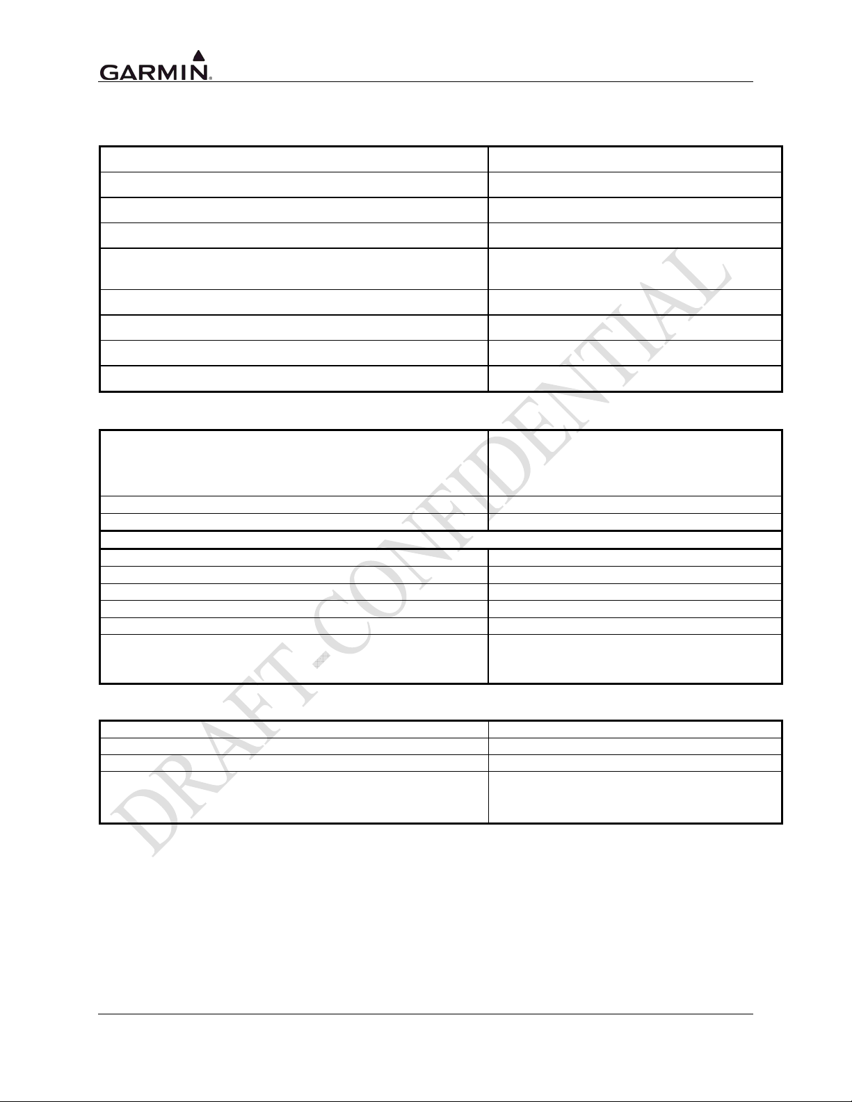
1.3 Technical Specifications
1.3.1 Physical Characteristics
Bezel Height
Bezel Width
Rack Height (Dimple-to-Dimple)
Rack Width
Depth Behind Panel with Connectors (Measured from
face of aircraft panel to rear of connector backshells)
GTN 725 Weight (Unit only)
GTN 725 Weight (With rack and back plate)
GTN 750 Weight (Unit only)
GTN 750 Weight (With rack and back plate)
1.3.2 General Specifications
Operating Temperature Range
Humidity
Altitude Range
Input Power Requirements
Input Voltage Range - All Units (Main Connector)
Input Voltage Range (COM Connector on GTN 750)
Input Voltage Range (NAV Connector on GTN 750)
GTN Current Draw
Superflag Power Requirements
Environmental Testing
6.00 in. (152 mm)
6.25 in. (159 mm)
6.025 in. (153 mm)
6.300 in (160 mm)
11.25 in. (286 mm)
TBD
TBD
7.50 lbs (3.40 kg)
9.16 lbs (4.15 kg)
-20°C to +55°C. For more details see
Environmental Qualification Form on the
Dealers Only page on www.garmin.com. See
Appendix A for part numbers.
95% non-condensing
-1,500 ft to 50,000 ft
9 to 33 VDC
9 to 33 VDC
9 to 33 VDC
Refer to Table 1-2
400 mA maximum per superflag output
See Environmental Qualification Form on the
Dealers Only page on www.garmin.com. See
Appendix A for part numbers.
The display on the GTN is a sunlight readable LCD display.
Display Size
Active Area
Resolution
Viewing Angle
6.9 inch diagonal
4.46 inches (W) x 5.27 inches (H)
600 x 708 pixels
Left/Right: 45°
Up: 10°
Down: 30°
Page 1-2 GTN 725/750 TSO Installation Manual
Rev. A 190-01007-02
Page 15
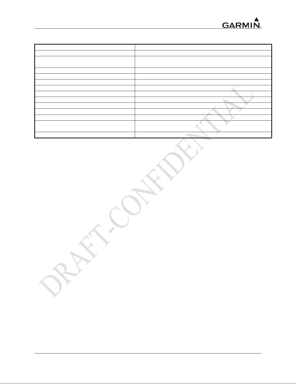
1.3.3 GPS Specifications
Number Of Channels
Frequency
Sensitivity (Acquisition, No Interference)
Sensitivity (Drop Lock)
Dynamic Range
Lat/Lon Position Accuracy
Velocity
TTFF (Time To First Fix)
Reacquisition
Position Update Interval
1 PPS (Pulse Per Second)
Datum
SATCOM Compatibility
Antenna Power Supply
15 (12 GPS and 3 GPS/WAAS/SBAS)
1575.42 MHz L1, C/A code
-134.5 dBm GPS
-135.5 dBm WAAS
-144 dBm
> 20 dB
<1.25 meter RMS horizontal, <2 meter vertical, with WAAS
1000 knots maximum (above 60,000 ft)
1:45 min. typical with current almanac, position, and time
10 seconds typical
0.2 sec (5 Hz)
±275 Nsec of UTC second
WGS-84
SATCOM compatibility is dependent upon antenna selection.
See Section TBD for additional information.
35 mA typical, 40 mA max at 4.7 VDC
GTN 725/750 TSO Installation Manual Page 1-3
190-01007-02 Rev. A
Page 16
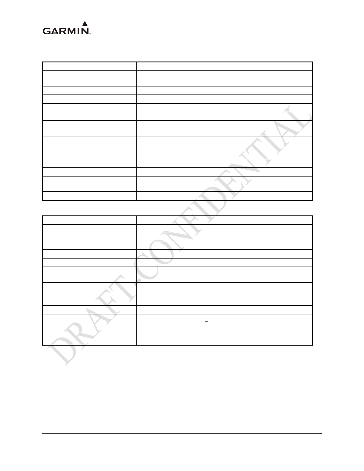
1.3.4 COM Specifications (GTN 750 Only)
1.3.4.1 COM Transmitter Specifications
Classes
Microphone Input
Modulation Capability
Modulation
Frequency Range
Frequency Tolerance
Output Power
Duty Cycle
Carrier Noise Level
Stuck Mic Time-Out
Demodulated Audio Distortion
Sidetone
3,4,5,6
Two inputs, standard carbon or dynamic mic with integrated
preamp providing minimum 70 mVRMS into 1000 load
85% with 100 to 1000 mVRMS microphone input at 1000 Hz
AM Double sided, Emission Designator 6K00A3E
118.000 to 136.975 MHz, 25 kHz and 8.33 kHz channel spacing
+/-2ppm from -40°C to +70°C
10 Watt Mode: 10 watts minimum
16 Watt Mode: 16 watts minimum
10W: 100%
16W: Recommended 25% (15 seconds on/45 seconds off,
5 seconds on/15 seconds off, etc.)
At least 35 dB (SNR).
35 seconds time-out, reverts to receive
Less than 5% distortion when the transmitter is at 85%
modulation at 350 to 2500 Hz
1.4 Vrms into a 500 load
1.3.4.2 COM Receiver Specifications
Classes
Frequency Range
Headset Audio Output
Speaker Audio Output
Audio Response
Audio Distortion
AGC Characteristics
Sensitivity
Squelch
Selectivity
D and E
118.000 to 136.975 MHz, 25 kHz and 8.33 kHz channel spacing
110 mW minimum into a 500 load
12 watts minimum into a 4 load
Less than 6 dB of variation between 350 and 2500 Hz.
Less than 5% at rated output power
Less than 3 dB of variation in the audio output from -93 to -13
dBm (power absorbed by a 50Ω load)
SINAD on all channels is greater than 6 dB when the RF level is
2 uV (hard) or -107 dBm (power absorbed by a 50Ω load)
modulated 30% at 1000 Hz at rated audio output power
Automatic squelch with manual override
6 dB BW is greater than +
60 dB BW is less than ±22 kHz for 25 kHz channeling.
6 dB BW is greater than ±3.5 kHz for 8.33 kHz channeling.
60 dB BW is less than ±7.37 kHz for 8.33 kHz channeling.
7 kHz for 25 kHz channeling.
Page 1-4 GTN 725/750 TSO Installation Manual
Rev. A 190-01007-02
Page 17
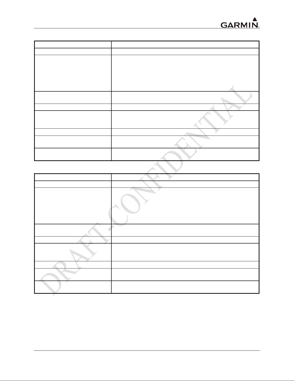
1.3.5 VOR Specifications (GTN 750 Only)
Receiver Audio Sensitivity
Course Deviation Sensitivity
Flag
AGC Characteristics
Spurious Response
VOR OBS Bearing Accuracy
Audio Output
Audio Response
Audio Distortion
At -103.5 dBm (S+N)/N is not less than 6 dB.
-103.5 dBm or less for 60% of standard deflection.
The VOR Course Deviation Flag must be flagged:
in the absence of an RF signal.
in the absence of the 9960 Hz modulation.
in the absence of either one of the two 30 Hz modulations.
When the level of a standard VOR deviation test signal produces
less than a 50% of standard deflection.
From -99 dBm to -13 dBm input of a Standard VOR Audio Test
Signal, audio output level does not vary more than 3 dB.
Greater than 80 dB.
The bearing information as presented to the pilot does not have an
error in excess of 2.7° as specified by RTCA DO-196 and
EuroCAE ED-22B.
A minimum 100 mW into a 500Ω load.
Less than 6 dB of variation between 350 and 2500 Hz. Except the
1020 Hz Ident Tone is at least 20 dB down in voice mode.
The distortion in the receiver audio output does not exceed 10% at
all levels up to 100 mW.
1.3.6 LOC Specifications (GTN 750 Only)
Receiver Audio Sensitivity
Course Deviation Sensitivity
Flag
AGC Characteristics
Spurious Response
VOR OBS Bearing Accuracy
Audio Output
Audio Response
Audio Distortion
At -103.5 dBm (S+N)/N is not less than 6 dB.
-103.5 dBm or less for 60% of standard deflection.
The VLOC Course Deviation Flag must be flagged:
in the absence of an RF signal.
in the absence of the 9960 Hz modulation.
in the absence of either one of the two 30 Hz modulations.
When the level of a standard VOR deviation test signal produces
less than a 50% of standard deflection.
From -99 dBm to -13 dBm input of a Standard VOR Audio Test
Signal, audio output level does not vary more than 3 dB.
Greater than 80 dB.
The bearing information as presented to the pilot does not have an
error in excess of 2.7° as specified by RTCA DO-196 and
EuroCAE ED-22B.
A minimum 100 mW into a 500Ω load.
Less than 6 dB of variation between 350 and 2500 Hz. Except the
1020 Hz Ident Tone is at least 20 dB down in voice mode.
The distortion in the receiver audio output does not exceed 10% at
all levels up to 100 mW.
GTN 725/750 TSO Installation Manual Page 1-5
190-01007-02 Rev. A
Page 18
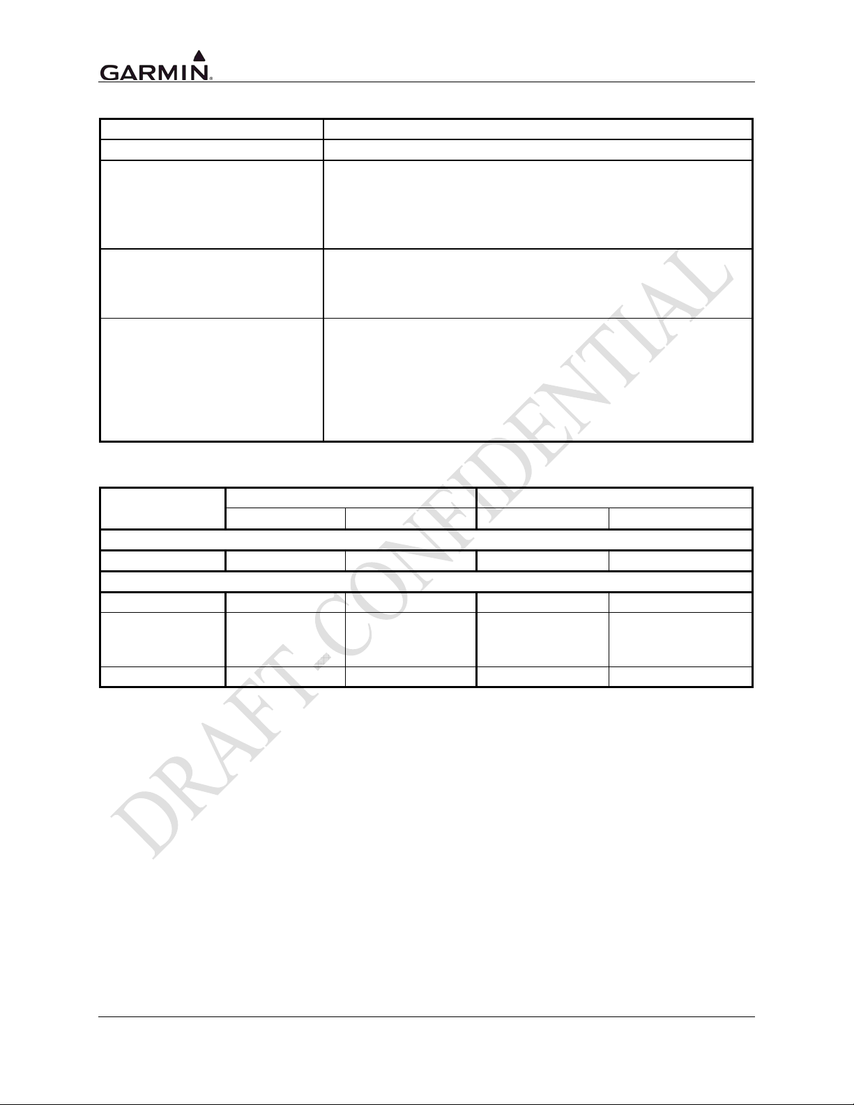
1.3.7 Glideslope Specifications (GTN 750 Only)
Sensitivity
Centering Accuracy
Selectivity
Standard Deflection
Flag
-87 dBm or less for 60% of standard deflection.
0 ±.0091 ddm or 0 ±7.8 mV.
The course deviation is 0 ddm ± .0091 ddm when using the
Glideslope Centering Test Signal as the RF frequency is varied
±17 kHz from the assigned channel.
At frequencies displaced by ±132 kHz or greater, the input signal is
at least 60 dB down.
a) With a standard deflection ‘FLY DOWN’ condition (90 Hz
dominant), the output is -78 mV ±7.8 mV.
b) With a standard deflection ‘FLY UP’ condition (150 Hz
dominant), the output is +78 mV ±7.8 mV.
The unit Flags:
When the level of a standard deviation test signal produces 50% or
less of standard deflection of the deviation indicator.
In the absence of 150 Hz modulation.
In the absence of 90 Hz modulation.
In the absence of both 90 Hz and 150 Hz modulation.
In the absence of RF.
Table 1-2. GTN Current Specifications
LRU
GTN 725
Main Connector 1.123 A
GTN 750
Main Connector 1.123 A
COM Connector 470 mA (RX)
NAV Connector 308 mA
14 Volt Current Draw 28 Volt Current Draw
Typical Maximum Typical Maximum
220 mA (RX)
5.16 A (TX:10W)
6.93 A (TX:16W)
2.04 A (TX:10W)
2.73 A (TX:16W)
Page 1-6 GTN 725/750 TSO Installation Manual
Rev. A 190-01007-02
Page 19
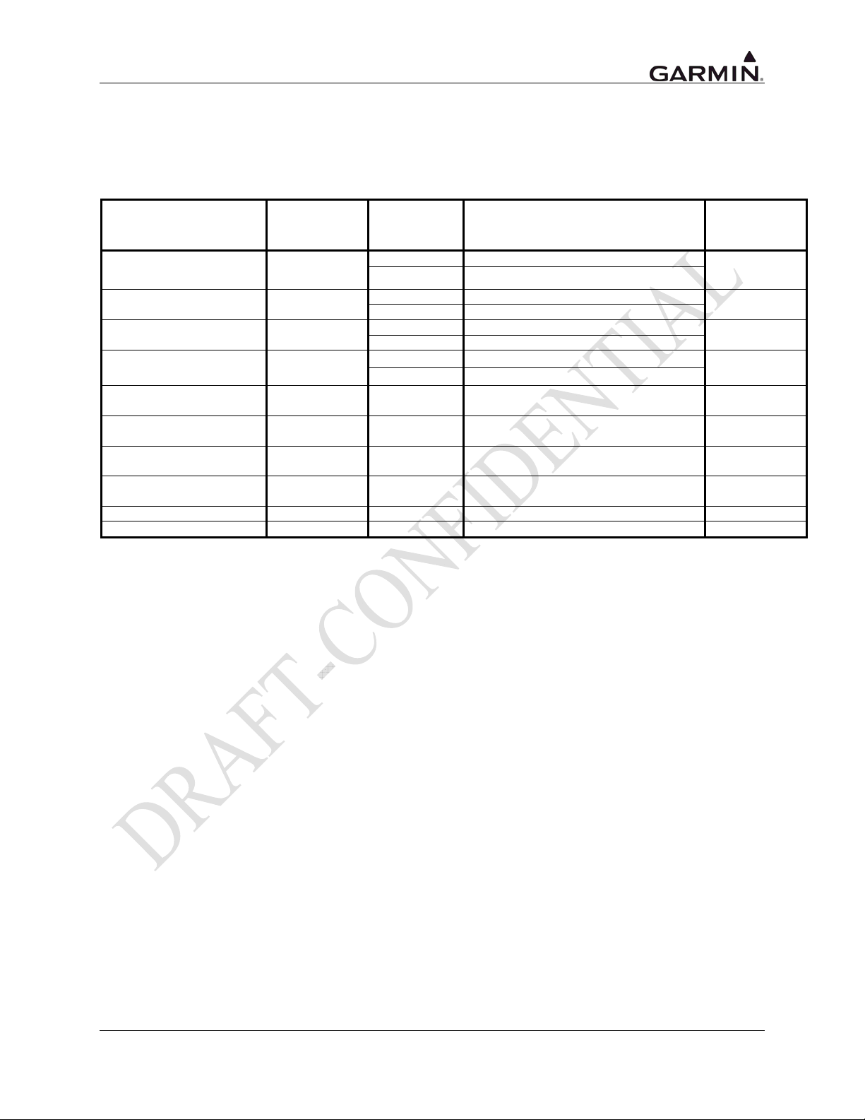
1.3.8 GPS Antenna Requirements
Antenna performance is critical to the GPS/WAAS operation. The antennas listed in Table 1-3 are
approved for installation with the GTNs.
Table 1-3. Approved GPS Antennas
Model/Description Conn Type Mfr Part Number
GA 35, GPS/WAAS
[1]
GA 36, GPS/WAAS TNC
GA 37, GPS/WAAS/XM TNC
A33W, WAAS Antenna
[3]
GPS/VHF Antenna
GPS/VHF Antenna
GPS/XM/VHF Antenna
GPS/XM/VHF Antenna
GPS Antenna TNC Comant [3] CI-428-200 N/A
GPS/XM Antenna TNC/TNC Comant [3] CI-428-410 N/A
TNC
TNC
TNC/BNC
[2]
TNC/BNC
[2]
TNC/TNC/BNC
[4]
TNC/TNC/BNC
[4]
Garmin 013-00235-( )
Aero Antenna AT575-93G( )-TNCF-000-RG-27-NM
Garmin 013-00244-( )
Aero Antenna AT575-126G( )-TNCF-000-RG-27-NM
Garmin 013-00245-( )
Aero Antenna AT2300-126G( )-TNCF-000-RG-27-NM
Garmin 013-00261-( )
Aero Antenna AT575-332G( )- TNCF-000-RG-27-NM
Comant [3] CI-2580-200 N/A
Comant [3] CI-2728-200 N/A
Comant [3] CI-2580-410 N/A
Comant [3] CI-2728-410 N/A
Garmin
Order
Number
013-00235-( )
013-00244-( )
013-00245-( )
013-00261-( )
[1] Same mounting hole pattern as GA 56, but GA 35 antenna has a physically larger footprint.
[2] The GPS/WAAS connector is a TNC type. The VHF connector is a BNC type.
[3] Installation of this antenna is not covered by the Garmin GA Antenna AML STC SA01695SE.
[4] The GPS/WAAS connector is a TNC type. The XM connector is a TNC type. The VHF connector is
a BNC type.
GTN 725/750 TSO Installation Manual Page 1-7
190-01007-02 Rev. A
Page 20

1.4 License Requirements
The Telecommunications Act of 1996, effective February 8, 1996, provides the FCC discretion to
eliminate radio station license requirements for aircraft and ships. The GTN 725 and GTN 750
installations must comply with current transmitter licensing requirements. In the US, to find out the
specific details on whether a particular installation is exempt from licensing, please visit the FCC web site
http://wireless.fcc.gov/aviation. If an aircraft license is required, make application for a license on FCC
form 404, Application for Aircraft Radio Station License. The FCC also has a fax-on-demand service to
provide forms by fax. Outside the US, contact the responsible telecommunication authority. The GTN
725 and GTN 750 owner accepts all responsibility for obtaining the proper licensing before using the
transceiver. The maximum transmitting power, modulation identification, and frequency band
information may be required for licensing and are detailed in Section 1.4.4.
CAUTION
The VHF transmitter in this equipment is guaranteed to meet Federal Communications
Commission acceptance over the operating temperature range. Modifications not
expressly approved by Garmin could invalidate the license and make it unlawful to
operate the equipment.
Page 1-8 GTN 725/750 TSO Installation Manual
Rev. A 190-01007-02
Page 21
1.5 Regulatory Compliance
1.5.1 TSO Authorization and Advisory Circular References
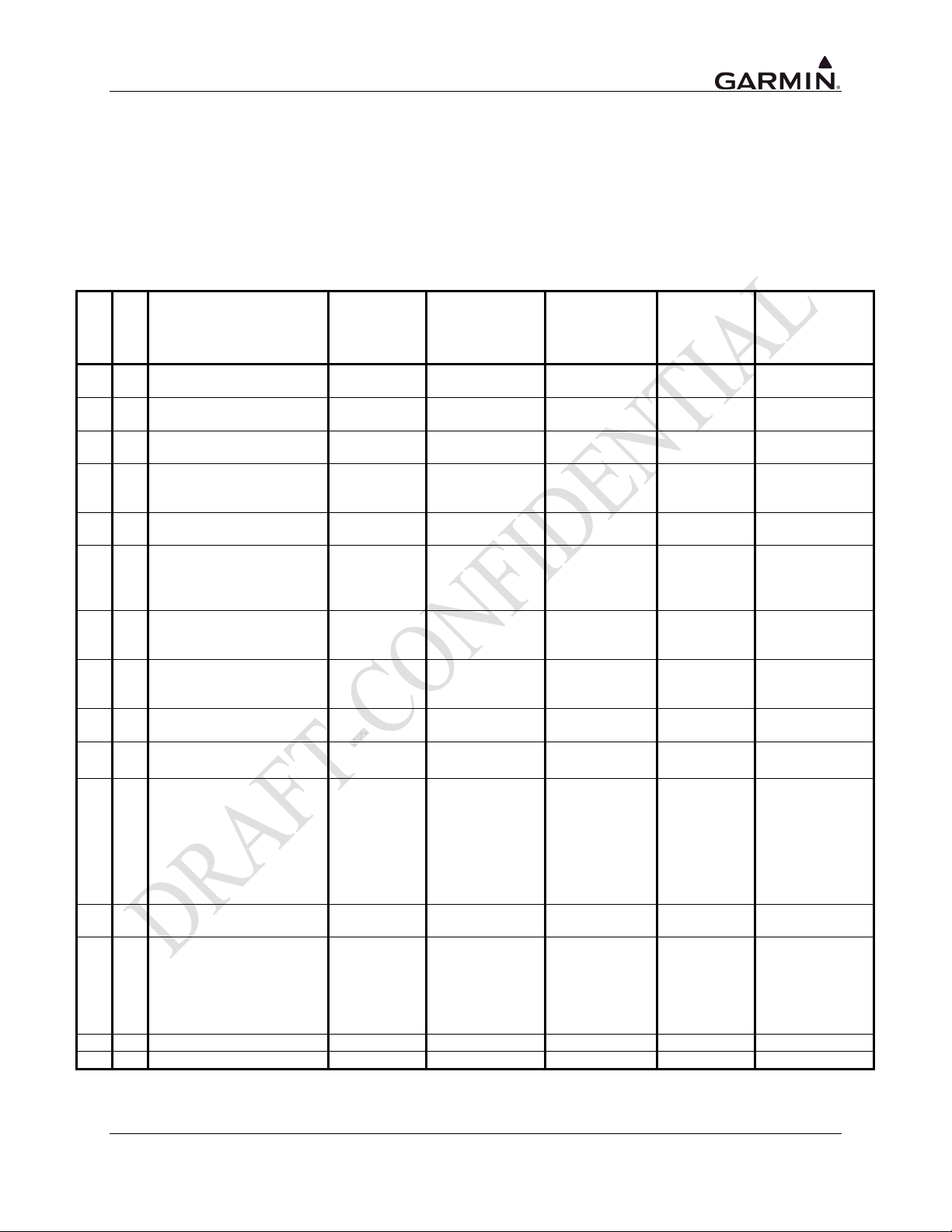
The conditions and tests required for TSO approval of this article are minimum performance standards. It
is the responsibility of those installing this article either on or within a specific type or class of aircraft to
determine that the aircraft installation conditions are within the TSO standards. TSO articles must have
separate approval for installation in an aircraft. The article may be installed only in compliance with
14 CFR part 43 or the applicable airworthiness requirements.
Table 1-4. TSO Authorization
Minimum
Applicable SW
P/Ns
GTN 725
GTN 750
●
●
●
● ●
● ●
● ●
● ●
● ●
● ●
● ●
Function TSO
ILS Glideslope Receiving
Equipment
ILS Localizer Receiving
Equipment
VOR Receiving
Equipment
Airborne Weather and
Ground Mapping Pulsed
Radars
Airborne ATC
Transponder Equipment
Optional Display
Equipment for Weather
and Ground Mapping
Radar Indicators
Airborne Passive
Thunderstorm Detection
Equipment
Air Traffic Control Radar
Beacon System/Mode
Select ATCRABS/Mode S
Multipurpose Electronic
Displays
TCAS Airborne
Equipment
Environmental
Standard
TSO-C34e DO-160B DO-192 TBD
TSO-C36e DO-160B DO-195 TBD
TSO-C40c DO-160B DO-196 TBD
TSO-C63c DO-160A DO-173 TBD
TSO-C74d DO-160F DO-144A TBD
TSO-C105 DO-160A DO-174 TBD
TSO-C110a DO-160B DO-191 TBD
TSO-C112c DO-160F DO-181D TBD
TSO-C113 DO-160A AS 8034 TBD
TSO-C118 DO-160B DO-197 TBD
Operational
Performance
Standard
Class/Type
Equipment that
Prevents Blocked
Channels in
●
2-way Radio
TSO-C128a DO-160E DO-207 TBD
Communications due to
Unintentional
Transmissions
● ●
● ●
● ● TAS Airborne Equipment TSO-C147 DO-160D DO-197A TBD
● ● TAWS TSO-C151b DO-160E TSO-C151b TBD
Aircraft Audio Systems
and Equipment
Stand-Alone Airborne
Navigation Equipment
using the GPS
Augmented by the
Satellite Based
Augmentation System
TSO-C139 DO-160E DO-214 TBD
TSO-C146c DO-160E DO-229D TBD
GTN 725/750 TSO Installation Manual Page 1-9
190-01007-02 Rev. A
Page 22
GTN 725
GTN 750
● ●
● ●
●
Function TSO
Aircraft Flight Information
Services – Broadcast
(FIS-B) Datalink Systems
and Equipment
Electronic Map Display
Equipment for Graphical
Depiction of Aircraft
Position
VHF Radio
Communications
Transceiver Equipment
Operating with Radio
Frequency Range
117.975 to 137.000 MHz
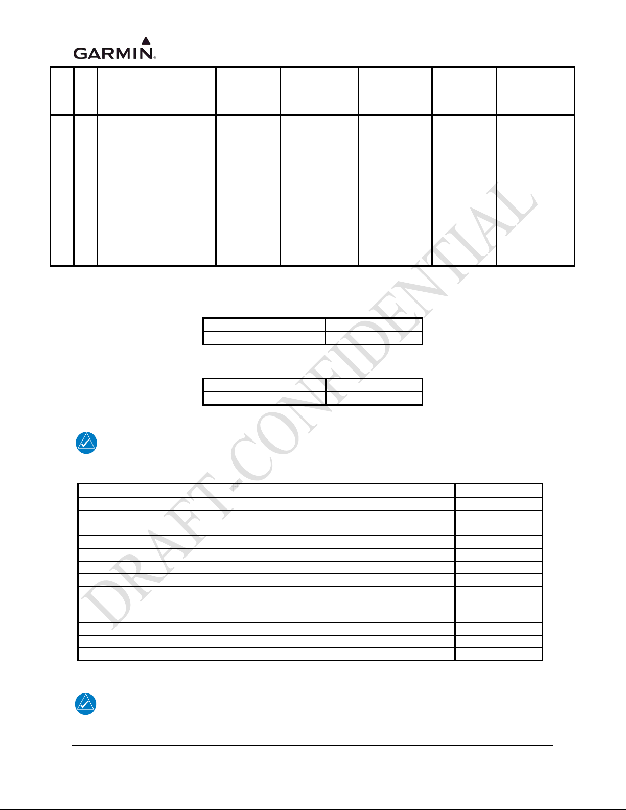
Table 1-5. Main Software Part Number and Version
Minimum
Environmental
Standard
TSO-C157 DO-160E DO-267A TBD
TSO-C165 DO-160E DO-257A TBD
TSO-C169a DO-160E DO-186B TBD
Operational
Performance
Standard
Class/Type
Applicable SW
Software Part Number Software Version
TBD TBD
P/Ns
Table 1-6. GPS/WAAS Software Part Number and Version
Software Part Number Software Version
006-B0339-10 V4.0
NOTE
For main or GPS software versions previous to those listed Table 1-5 or Table 1-6,
contact Garmin for assistance.
System Function DO-178B Level
Operating System B
GPS Navigation Information B
VOR Information C
LOC/Glideslope Information C
VHF Communication C
TAWS (Class B) Functionality C
Display of altitude, heading, course, speed, and track C
Display of other information - moving map, terrain, flight plan overlay and flight
mode, TAS/TIS traffic information, XM Weather data, data from passive lightning
detection equipment, checklist and timer
Terrain (Fixed Wing) D
Terrain Prox (Helicopter) D
HTAWS (Helicopter) C
D
NOTE
Unauthorized changes or modifications to any GTN unit product may void the
compliance to required regulations and authorization for continued equipment usage. All
GTN unit functions are design approved under the TSO.
Page 1-10 GTN 725/750 TSO Installation Manual
Rev. A 190-01007-02
Page 23
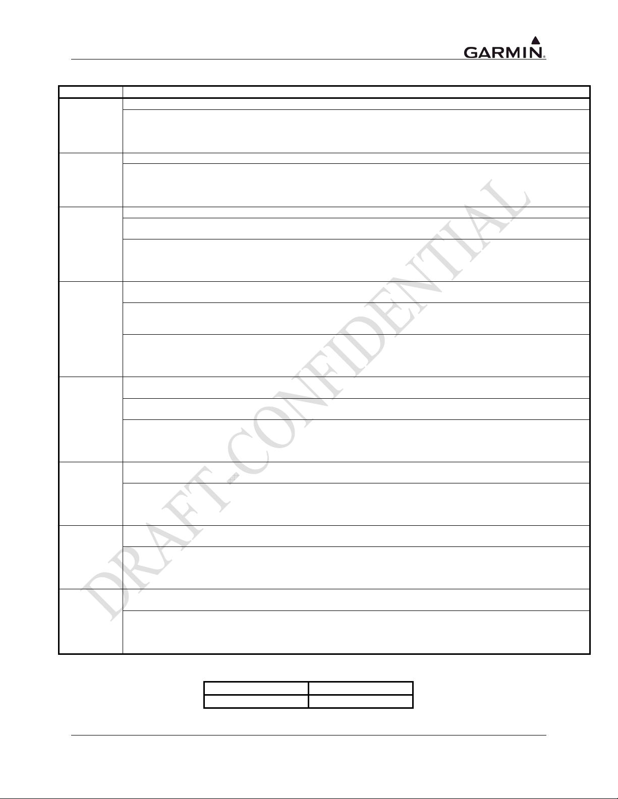
1.5.2 TSO Deviations
TSO Deviation
1. Garmin was granted a deviation from TSO-C110 not to mark the computer software level(s) on the unit.
TSO-C110
TSO-C113
TSO-C118
TSO-C139
TSO-C146c
TSO-C147
TSO-C151b
TSO-C165
2. Garmin was granted a deviation from the TSO-C110 to mark product name, part number, serial number and a
statement on the unit’s nameplate label “TSO-C146c Class 3, See IM for Add’l Appliance Approvals ”, instead of
Product Type, TSO Numbers, Equipment Class, “Dev” (deviation), Environmental Categories, Date of
Manufacture, weight and Software Part Number.
1. Garmin was granted a deviation from TSO-C113 not to mark the computer software level(s) on the unit.
2. Garmin was granted a deviation from TSO-C113 to mark product name, part number, serial number and a
statement on the unit’s nameplate label “TSO-C146c Class 3, See IM for Add’l Appliance Approvals ”, instead of
Product Type, TSO Numbers, Equipment Class, “Dev” (deviation), Environmental Categories, Date of
Manufacture, weight and Software Part Number.
1. Garmin was granted a deviation from TSO-C118 not to mark the computer software level(s) on the unit.
2. Garmin was granted a deviation from TSO-C118 to use RTCA/DO-197A instead of RTCA/DO-197 as the
Minimum Operational Performance Standards.
3. Garmin was granted a deviation from TSO-C118 to mark product name, part number, serial number and a
statement on the unit’s nameplate label “TSO-C146c Class 3, See IM for Add’l Appliance Approvals ”, instead of
Product Type, TSO Numbers, Equipment Class, “Dev” (deviation), Environmental Categories, Date of
Manufacture, weight and Software Part Number.
1. Garmin was granted a deviation from TSO-C139 not to furnish each person receiving a GTN 725/750 copies of
the data in Paragraph 5.l of the TSO.
2. Garmin was granted a deviation from TSO-C139 not to furnish each person receiving a GTN 725/750 copies of
the data in Paragraph 5.l, 5.m, 5.n of the TSO, if the equipment performs functions beyond those in paragraph 3
and paragraph 3.a.
3. Garmin was granted a deviation from TSO-C139 to mark product name, part number, serial number and a
statement on the unit’s nameplate label “TSO-C146c Class 3, See IM for Add’l Appliance Approvals ”, instead of
Product Type, TSO Numbers, Equipment Class, “Dev” (deviation), Environmental Categories, Date of
Manufacture, weight and Software Part Number.
1. Garmin was granted a deviation from RTCA/DO-229D to use a 10 degree vertical viewing angle below the
lower display edge.
2. Garmin was granted a deviation from RTCA/DO-229D to use GPS antennas that meet Garmin minimum
performance specifications.
3. Garmin was granted a deviation from TSO-C146c to mark product name, part number, serial number and a
statement on the unit’s nameplate label “TSO-C146c Class 3, See IM for Add’l Appliance Approvals ”, instead of
Product Type, TSO Numbers, Equipment Class, “Dev” (deviation), Environmental Categories, Date of
Manufacture, weight and Software Part Number.
1. Garmin was granted a deviation from TSO-C147 not to furnish each person receiving a GTN 725/750 copies of
the data in paragraphs 3(a)(10) through (12) of the TSO.
2. Garmin was granted a deviation from TSO-C147 to mark product name, part number, serial number and a
statement on the unit’s nameplate label “TSO-C146c Class 3, See IM for Add’l Appliance Approvals ”, instead of
Product Type, TSO Numbers, Equipment Class, “Dev” (deviation), Environmental Categories, Date of
Manufacture, weight and Software Part Number.
1. Garmin was granted a deviation from TSO-C151b Section 5.c(2) not to furnish each person receiving a GTN
725/750 copies of the data in paragraphs 5.a(11) through (13) of the TSO.
2. Garmin was granted a deviation from TSO-C151b to mark product name, part number, serial number and a
statement on the unit’s nameplate label “TSO-C146c Class 3, See IM for Add’l Appliance Approvals ”, instead of
Product Type, TSO Numbers, Equipment Class, “Dev” (deviation), Environmental Categories, Date of
Manufacture, weight and Software Part Number.
1. Garmin was granted a deviation from TSO-C165 Section 5.c(2) not to furnish each person receiving a GTN
725/750 copies of the data in paragraphs 5.a(11) through (13) of the TSO.
2. Garmin was granted a deviation from TSO-C165 to mark product name, part number, serial number and a
statement on the unit’s nameplate label “TSO-C146c Class 3, See IM for Add’l Appliance Approvals ”, instead of
Product Type, TSO Numbers, Equipment Class, “Dev” (deviation), Environmental Categories, Date of
Manufacture, weight and Software Part Number.
1.5.3 FCC Grant of Equipment Authorization
Model FCC ID
GTN 750 IPH-01594
GTN 725/750 TSO Installation Manual Page 1-11
190-01007-02 Rev. A
Page 24

1.6 Database Options and Updates
1.6.1 Navigation Database
The navigation database resides on a database card that is inserted in the card slot on the unit front panel.
The database is generated on periodic cycles from current Jeppesen data and converted to the format used
by the GTN products. The data conversion process is performed using software that is developed and
maintained under Garmin document control processes according to RTCA/DO-200A, Standards for
Processing Aeronautical Data.
The database can be updated by purchasing a database subscription from Jeppesen. The database updates
include either replacing or re-programming the database card and inserting the updated card in the left
card slot on the unit front panel. Contact Jeppesen at 800-621-5377 or www.jeppesen.com for more
information and instructions.
Contact Garmin for more information on databases available for the GTN.
1.6.2 TAWS/Terrain Database
The TAWS/Terrain database resides on a database card that is inserted in the card slot on the unit front
panel.
The TAWS/Terrain database which serves both functions of Terrain Awareness and Warning System
(TAWS) and the standard configured GTN providing terrain functionality is available for updating on
periodic cycles and is available from Garmin. TAWS/Terrain database updates can be accomplished by
replacing or reprogramming the database card and inserting the updated card in the card slot on the unit
front panel. The TAWS/Terrain database can be downloaded via the internet and the card programmed
using a USB programmer available from Garmin. Contact Garmin at 800-800-1020 or www.garmin.com
for more information or instructions.
1.7 Fault Detection and Exclusion (FDE)
The GTN unit, when installed as defined in this manual, complies with the requirements for GPS primary
means navigation in oceanic and remote airspace when used in conjunction with the FDE Prediction
program.
The GTN unit includes fault detection and exclusion (FDE), which is active for all flight phases including
oceanic and remote operations, en route and terminal, and precision and non-precision approaches, and
does not require any pilot interaction. The FDE consists of two parts:
1. The fault detection function detects a satellite failure that can affect navigation; and
2. The exclusion function is the capability to exclude one or more failed satellites and prevent them
from affecting navigation.
The FDE Prediction program is used to predict FDE availability. The FDE Prediction program must be
used prior to oceanic or remote area flights for all operators using the GTN unit as primary means
navigation under FAR parts 91, 121, 125, and 135.
Page 1-12 GTN 725/750 TSO Installation Manual
Rev. A 190-01007-02
Page 25

1.8 Limited Warranty
All Garmin avionics products are warranted to be free from defects in materials or workmanship for: two
years from the date of purchase for new Remote-Mount and Panel-Mount products; one year from the
date of purchase for new portable products and any purchased newly-overhauled products; six months for
newly-overhauled products exchanged through a Garmin Authorized Service Center; and 90 days for
factory repaired or newly-overhauled products exchanged at Garmin in lieu of repair. Within the
applicable period, Garmin will, at its sole option, repair or replace any components that fail in normal use.
Such repairs or replacement will be made at no charge to the customer for parts or labor, provided that the
customer shall be responsible for any transportation cost. This warranty does not apply to: (i) cosmetic
damage, such as scratches, nicks and dents; (ii) consumable parts, such as batteries, unless product
damage has occurred due to a defect in materials or workmanship; (iii) damage caused by accident, abuse,
misuse, water, flood, fire, or other acts of nature or external causes; (iv) damage caused by service
performed by anyone who is not an authorized service provider of Garmin; or (v) damage to a product
that has been modified or altered without the written permission of Garmin. In addition, Garmin reserves
the right to refuse warranty claims against products or services that are obtained and/or used in
contravention of the laws of any country.
THE WARRANTIES AND REMEDIES CONTAINED HEREIN ARE EXCLUSIVE AND IN LIEU OF
ALL OTHER WARRANTIES, WHETHER EXPRESS, IMPLIED OR STATUTORY, INCLUDING
ANY LIABILITY ARISING UNDER ANY WARRANTY OF MERCHANTABILITY OR FITNESS
FOR A PARTICULAR PURPOSE, STATUTORY OR OTHERWISE. THIS WARRANTY GIVES
YOU SPECIFIC LEGAL RIGHTS, WHICH MAY VARY FROM STATE TO STATE.
IN NO EVENT SHALL GARMIN BE LIABLE FOR ANY INCIDENTAL, SPECIAL, INDIRECT OR
CONSEQUENTIAL DAMAGES, WHETHER RESULTING FROM THE USE, MISUSE OR
INABILITY TO USE THE PRODUCT OR FROM DEFECTS IN THE PRODUCT. SOME STATES DO
NOT ALLOW THE EXCLUSION OF INCIDENTAL OR CONSEQUENTIAL DAMAGES, SO THE
ABOVE LIMITATIONS MAY NOT APPLY TO YOU.
Garmin retains the exclusive right to repair or replace (with a new or newly-overhauled replacement
product) the product or software or offer a full refund of the purchase price at its sole discretion. SUCH
REMEDY SHALL BE YOUR SOLE AND EXCLUSIVE REMEDY FOR ANY BREACH OF
WARRANTY.
Online Auction Purchases: Products purchased through online auctions are not eligible for warranty
coverage. Online auction confirmations are not accepted for warranty verification. To obtain warranty
service, an original or copy of the sales receipt from the original retailer is required. Garmin will not
replace missing components from any package purchased through an online auction.
International Purchases: A separate warranty may be provided by international distributors for devices
purchased outside the United States depending on the country. If applicable, this warranty is provided by
the local in-country distributor and this distributor provides local service for your device. Distributor
warranties are only valid in the area of intended distribution. Devices purchased in the United States or
Canada must be returned to the Garmin service center in the United Kingdom, the United States, Canada,
or Taiwan for service.
GTN 725/750 TSO Installation Manual Page 1-13
190-01007-02 Rev. A
Page 26

This page intentionally left blank
Page 1-14 GTN 725/750 TSO Installation Manual
Rev. A 190-01007-02
Page 27

2. INSTALLATION OVERVIEW
2.1 Introduction
Always follow acceptable avionics installation practices per AC 43.13-1B, AC 43.13-2B, or later FAA
approved revisions of these documents. The GPS/WAAS installation instructions have been prepared to
meet the guidance material contained in AC 20-138A “Airworthiness Approval of Global Navigation
Satellite System (GNSS) Equipment”. The communications installation instructions have been prepared
to meet the guidance material defined by AC 20-67B, “Airborne VHF Communications Equipment
Installations”.
2.2 Minimum System Configuration
2.2.1 VFR Installation
The minimum GTN installation requires the following items for a VFR Installation:
• GTN (installed in the aircraft manufacturer approved location for 6.25” wide avionics equipment)
• GPS antenna is required for GPS navigation functions.
• An external CDI is required for installations using the VOR navigation and glideslope
information.
• A NAV antenna is required for VHF NAV functions.
• A COM antenna is required for COM functions.
VFR installations must be placarded “GPS LIMITED TO VFR USE ONLY” in clear view of the pilot.
2.2.2 IFR GPS Installation
In order for the GTN to be utilized for IFR GPS Navigation, the criteria in Section 2.2.1 must be met in
addition to the following:
• An External CDI/HSI indicator must be installed in the pilot’s primary field-of-view (or in the
aircraft manufacturer approved mounting location). The indicator must have a vertical deviation
indicator (glideslope) in order to perform VNAV operations/approaches.
• Any annunciation required for Source Selection or IFR GPS Navigation must meet the acceptable
field-of-view requirements.
NOTE
To take full advantage of the GTN capabilities, an optional barometric altitude source is
recommended for automatic sequencing of fix-to-altitude (FA) and hold-to-altitude (HA)
leg types. If no barometric altitude data is provided to the GTN, FA and HA legs must be
manually sequenced.
GTN 725/750 TSO Installation Manual Page 2-1
190-01007-02 Rev. A
Page 28

2.2.3 IFR VOR/LOC/GLIDESLOPE Installation
The minimum GTN unit installation requires the following items for an IFR VOR/LOC/GLIDESLOPE
installation:
• GTN (installed in the aircraft manufacturer approved location)
• GPS antenna, NAV antenna, and COM antenna.
• An External CDI/HSI indicator must be installed in the pilot’s primary field-of-view (or in the
aircraft manufacturer approved mounting location). The indicator must have a vertical deviation
indicator for glideslope and VNAV operations/approaches.
• Any annunciation required for Source Selection or IFR GPS Navigation must meet the acceptable
field-of-view requirements.
• A second GPS navigator, COM radio, or NAV radio must be installed.
2.3 External Sensors
When GTN is installed with external sensors, these sensors must be installed in accordance with the
manufacturer's data. This manual does not provide information for the installation of specific external
sensors.
The GTN can accept data from multiple altitude, heading, and baro correction sources. If multiple sources
are used, the GTN will accept data as described below.
NOTE
Barometric altitude is not required by the GTN to meet the requirements of TSO C146a.
2.3.1 Multiple Uncorrected Pressure Altitude Sources
The GTN can accept altitude from a RS-232 altitude encoder, fuel/air data computer (FADC),
ARINC 429 air data computer (ADC), ARINC 429 EFIS, and ARINC 429 traffic advisory system. If
multiple sources of altitude data are supplied to the GTN, only valid data from the highest priority source
is used (input priority cannot be configured). If the highest priority source becomes unavailable, data is
taken from the next-highest priority source. The priorities of the altitude sources are as follows (from
highest to lowest):
1. ARINC 429 ADC
2. ARINC 429 ADC/AHRS
3. ARINC 429 GDU
4. ARINC 429 EFIS/ADC
5. ARINC 429 Data Concentrator
6. ARINC 429 Traffic Advisory System
7. RS-232 Shadin Fuel and ADC
8. RS-232 Shadin Altitude or Icarus Altitude
Page 2-2 GTN 725/750 TSO Installation Manual
Rev. A 190-01007-02
Page 29

2.3.2 Multiple Baro-Corrected Altitude Sources
The GTN unit can accept baro-corrected altitude from multiple ARINC 429 and RS-232 sources.
If multiple sources of baro-corrected altitude data are supplied to the GTN, only valid data from the
highest priority source is used. If the highest priority source becomes unavailable, data is taken from the
next-highest priority source. The priorities of the baro-corrected altitude sources are as follows from
highest to lowest:
1. ARINC 429 label 204 from Airdata
2. ARINC 429 label 204 from Garmin GDU
3. ARINC 429 label 204 from EFIS/Airdata
4. ARINC 429 label 204 from Data Concentrator
5. RS-232 bus from Shadin Fuel and Air Data Computer
2.3.3 Multiple Heading Sources
The GTN unit can accept heading data from multiple ARINC 429, RS-232, and Synchro sources. If
multiple sources of heading data are supplied to the GTN, only valid data from the highest priority source
is used. If the highest priority source becomes unavailable, data is taken from the next-highest priority
source. The priorities of the heading sources are as follows from highest to lowest:
1. ARINC 429 label 314 from EFIS or Honeywell EFIS
2. ARINC 429 label 320 from EFIS or Honeywell EFIS, corrected for local magnetic variation
3. ARINC 429 label 320 from EFIS/Airdata, corrected for local magnetic variation
4. ARINC 429 label 320 from Garmin GDU, corrected for local magnetic variation
5. ARINC 429 label 314 from INS/IRU
6. ARINC 429 label 314 from Data Concentrator
7. ARINC 429 label 320 from INS/IRU, corrected for local magnetic variation
8. ARINC 429 label 320 from Airdata/AHRS, corrected for local magnetic variation
9. ARINC 429 label 320 from Garmin GAD 42, corrected for local magnetic variation
10. ARINC 429 label 320 from Sandel EHSI, corrected for local magnetic variation
11. ARINC 429 label 314 from GAD 42
12. XYZ Synchro
13. ARINC 429 label 320 from Data Concentrator
14. ARINC 429 label 320 from Traffic Advisory, corrected for local magnetic variation
15. RS-232 bus from Shadin Fuel and Air Data Computer
16. RS-232 bus from WX-500
GTN 725/750 TSO Installation Manual Page 2-3
190-01007-02 Rev. A
Page 30

2.3.4 Multiple Indicated Airspeed Sources
The GTN unit can accept indicated airspeed data from multiple ARINC 429 and RS-232 sources. If
multiple sources of indicated airspeed data are supplied to the GTN, only valid data from the highest
priority source is used. If the highest priority source becomes unavailable, data is taken from the nexthighest priority source. The priorities of the indicated airspeed sources are as follows from highest to
lowest:
1. ARINC 429 label 206 from Garmin GDU
2. ARINC 429 label 206 from Airdata/AHRS
3. ARINC 429 label 206 from Data Concentrator
4. RS-232 bus from Shadin Fuel and Air Data Computer
2.3.5 Multiple True Airspeed Sources
The GTN unit can accept heading data from multiple ARINC 429 and RS-232 sources. If multiple
sources of true airspeed data are supplied to the GTN, only valid data from the highest priority source is
used. If the highest priority source becomes unavailable, data is taken from the next-highest priority
source. The priorities of the true airspeed sources are as follows from highest to lowest:
1. ARINC 429 label 210 from Airdata
2. ARINC 429 label 210 from Airdata/AHRS
3. ARINC 429 label 210 from Garmin GDU
4. ARINC 429 label 210 from EFIS/Airdata
5. ARINC 429 label 210 from Garmin GAD 42
6. ARINC 429 label 210 from Data Concentrator
7. RS-232 bus from Shadin Fuel and Air Data Computer
2.3.6 Multiple VLOC Course Select Sources
The GTN unit can accept VLOC course select data from the sources list below. If multiple sources of
VLOC course select data are supplied to the GTN, only valid data from the highest priority source is used.
If the highest priority source becomes unavailable, data is taken from the next-highest priority source. The
priorities of the VLOC course select sources are as follows from highest to lowest:
1. ARINC 429 label 100 from Sandel EHSI
2. ARINC 429 label 110 from Garmin GAD 42
3. TO/FROM course from the appliance’s Omni-Bearing Selector (OBS) control
Page 2-4 GTN 725/750 TSO Installation Manual
Rev. A 190-01007-02
Page 31

2.3.7 GPS Course Select Sources
The GTN unit can accept GPS course select data from multiple ARINC 429 sources. If multiple sources
of GPS course select data are supplied to the GTN, only valid data from the highest priority source is
used. If the highest priority source becomes unavailable, data is taken from the next-highest priority
source. The priorities of the GPS course select sources are as follows from highest to lowest:
1. ARINC 429 label 100 from EFIS or Honeywell EFIS
2. ARINC 429 label 100 from Garmin GDU
3. ARINC 429 label 100 from EFIS/Airdata
4. ARINC 429 label 100 from Sandel EHSI
5. ARINC 429 label 100 from Garmin GAD 42
6. ARINC 429 label 100 from Data Concentrator
7. TO/FROM course from the appliance's Omni-Bearing Selector (OBS) control
2.3.8 Total Air Temperature Sources
The GTN unit can accept total air temperature data from multiple ARINC 429 and RS-232 sources. If
multiple sources of total air temperature data are supplied to the GTN, only valid data from the highest
priority source is used. If the highest priority source becomes unavailable, data is taken from the nexthighest priority source. The priorities of the total air temperature sources are as follows from highest to
lowest:
1. ARINC 429 label 211 from Airdata
2. ARINC 429 label 211 from Garmin GDU
3. ARINC 429 label 211 from EFIS/Airdata
4. ARINC 429 label 211 from Data Concentrator
5. RS-232 bus from Shadin Fuel and Air Data Computer
2.3.9 Static Air Temperature Sources
The GTN unit can accept static air temperature data from multiple ARINC 429 sources. If multiple
sources of static air temperature data are supplied to the GTN, only valid data from the highest priority
source is used. If the highest priority source becomes unavailable, data is taken from the next-highest
priority source. The priorities of the static air temperature sources are as follows from highest to lowest:
1. ARINC 429 label 213 from Airdata
2. ARINC 429 label 213 from Garmin GDU
3. ARINC 429 label 213 from EFIS/Airdata
4. ARINC 429 label 213 from Data Concentrator
GTN 725/750 TSO Installation Manual Page 2-5
190-01007-02 Rev. A
Page 32

2.3.10 Joystick Waypoint Data
The GTN unit can accept joystick waypoint data from multiple ARINC 429 sources. If multiple sources
of joystick waypoint data are supplied to the GTN, only valid data from the highest priority source is
used. If the highest priority source becomes unavailable, data is taken from the next-highest priority
source. The priorities of the joystick waypoint data sources are as follows from highest to lowest:
1. ARINC 429 labels 306 and 307 from EFIS or Honeywell EFIS
2. ARINC 429 labels 306 and 307 from Garmin GDU
3. ARINC 429 labels 306 and 307 from EFIS/Airdata
4. ARINC 429 labels 306 and 307 from Radar Graphics
5. ARINC 429 labels 306 and 307 from Garmin GAD 42
6. ARINC 429 labels 306 and 307 from Data Concentrator
Page 2-6 GTN 725/750 TSO Installation Manual
Rev. A 190-01007-02
Page 33

2.4 Antenna Considerations
This section contains mounting location considerations for the antennas required for the GTN units.
Structural substantiation for mounting of antennas is beyond the scope of the GTN AML STC. For
mounting the GA GPS/WAAS antenna, refer to Garmin GA Antenna AML STC SA01695SE or other
FAA approved data. For mounting the COM and NAV antennas, refer to the aircraft manufacturer’s data.
2.4.1 GPS Antenna Location
The GPS antenna is a key element in the overall system performance and integrity for a GPS/WAAS
navigation system. The mounting location, geometry, and surroundings of the antenna can affect the
system performance and/or availability. The following guidance provides information to aid the installer
in ensuring that the most optimum location is selected for the installation of the GPS antenna. The
installation guidelines presented here meet the intent of AC 20-138A section 16. The greater the variance
from these guidelines, the greater the chance of decreased availability. Approach procedures with vertical
guidance are the most sensitive to these effects. LNAV only approaches, terminal operations, and enroute
operations may also be affected. Because meeting all of these installations guidelines may not be possible
on all aircraft, these guidelines are listed in order of importance to achieve optimum performance. Items 3
below are of equal importance and their significance may depend on the aircraft installation. The installer
should use their best judgment to balance the installation guidelines.
1. Mount the antenna as close to level as possible with respect to the normal cruise flight
attitude of the aircraft. If the normal flight attitude is not known, substitute the waterline,
which is typically referenced as level while performing a weight and balance check.
2. The GPS antenna should be mounted in a location to minimize the effects of airframe
shadowing during typical maneuvers. Typically mounting farther away from the tail section
reduces signal blockage seen by the GPS antenna.
3a. The GPS antenna should be mounted no closer than two feet from any VHF COM antenna or
any other antenna which may emit harmonic interference at the L1 frequency of
1575.42 MHz. An aircraft EMC check (reference VHF COM interference check in Post
Installation Checkout procedures) can verify the degradation of GPS in the presence of
interference signals. If an EMC check reveals unacceptable interference, insert a GPS notch
filter in line with the offending VHF COM or the (re-radiating) ELT transmitter.
Note: When mounting a combination antenna (ex. GPS and COM, GPS and XM), the
recommended distance of two feet or more is not applicable to the distance between
the antenna elements provided the combination antenna is TSO authorized and has
been tested to meet Garmin’s minimum performance standards.
3b. The GPS antenna should be mounted no closer than two feet from any antennas emitting
more than 25 watts of power. An aircraft EMC check can verify the degradation of GPS in
the presence of interference signals.
3c. To minimize the effects of shadowing at 5° elevation angles, the GPS antenna should be
mounted no closer than 6” (edge to edge) from other antennas, including passive antennas
such as another GPS antenna or XM antenna.
4. To maintain a constant gain pattern and limit degradation by the windscreen, avoid mounting
the antenna closer than 3 inches from the windscreen.
5. For multiple GPS installations, the antennas should not be mounted in a straight line from the
front to the rear of the fuselage. Also varying the mounting location will help minimize any
aircraft shading by the wings or tail section (in a particular azimuth, when one antenna is
blocked the other antenna may have a clear view).
Figure 2-1 shows the recommended placement of antennas.
GTN 725/750 TSO Installation Manual Page 2-7
190-01007-02 Rev. A
Page 34

2.4.2 COM Antenna Location
The GTN COM antenna should be well removed from all projections, engines and propellers. The ground
plane surface directly below the antenna should be a flat plane over as large an area as possible (18”
square, minimum). The antenna should be mounted a minimum of six feet from any DME or other COM
antennas, four feet from any ADF sense antennas, and two feet from the GTN and its GPS antenna. The
COM antenna should also be mounted as far apart as practical from the ELT antenna. Some ELTs have
exhibited re-radiation problems generating harmonics that may interfere with GPS signals. This can
happen when the COM (GTN or any other COM) is transmitting on certain frequencies such as 121.15 or
121.175 MHz, which may cause the ELT output circuit to oscillate from the signal coming in on the ELT
antenna coax.
If simultaneous use of two COM transceivers is desired (split-COM or simul-comm), use of the TX
interlock function is mandatory. In addition, the COM antennas should be spaced for maximum isolation.
A configuration of one topside antenna and one bottom side antenna is recommended.
Page 2-8 GTN 725/750 TSO Installation Manual
Rev. A 190-01007-02
Page 35
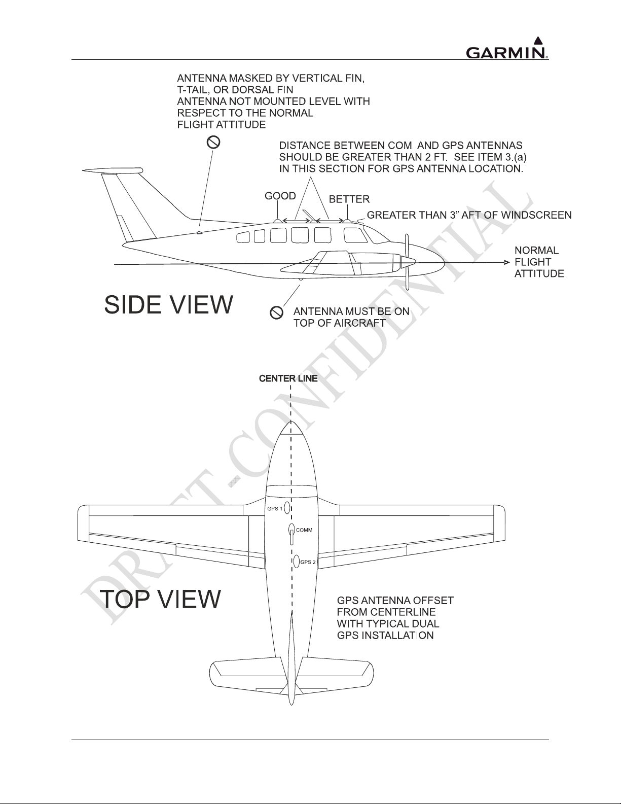
Figure 2-1. GPS Antenna Installation Considerations
GTN 725/750 TSO Installation Manual Page 2-9
190-01007-02 Rev. A
Page 36

2.4.3 VOR/LOC Antenna Location
The GTN VOR/LOC antenna should be well removed from all projections, engines and propellers. It
should have a clear line of sight if possible. The antenna must be mounted along the centerline of the
aircraft, minimizing the lateral offset.
2.4.4 Glideslope Antenna Location
The GTN Glideslope antenna should be well removed from all projections, engines and propellers. It
should have a clear line of sight if possible.
2.4.5 Electrical Bonding
No special precautions need to be taken to provide a bonding path between the GPS antenna and the
aircraft structure. Follow the manufacturers’ instructions for the COM, VOR/LOC and Glideslope
antennas.
2.4.6 Interference of GPS
On some installations, VHF COM transceivers, Emergency Locator Transmitter (ELT) antennas, and
Direction Finder (DF) receiver antennas can re-radiate through the GPS antenna. The GTN COM does
not interfere with its own GPS section. However, placement of the GPS antenna relative to a COM
transceiver and COM antenna (including the GTN COM antenna), ELT antenna, and
DF receiver antenna is critical.
Use the following guidelines, in addition to others in this document, when locating the GTN and its
antennas.
• GPS Antenna—Locate as far as possible from all COM antennas and all COM transceivers
(including the GTN COM), ELT antennas, and DF receiver antennas. The GPS antenna is less
susceptible to harmonic interference if a 1.57542 GHz notch filter is installed on the COM
transceiver antenna output.
• Locate the GTN as far as possible from all COM antennas.
If a COM antenna is found to be the problem, a 1.57542 GHz notch filter (Garmin P/N 330-00067-00)
may be installed in the VHF COM coax, as close to the COM as possible. This filter is not required for
the GTN transmitter.
If a COM is found to be radiating, the following can be done:
1. Replace or clean VHF COM rack connector to ensure good coax ground.
2. Place a grounding brace between the GTN, VHF COM and ground.
3. Shield the VHF COM wiring harness.
COM, VOR/LOC, and Glideslope Antenna Installation Instructions
Install the COM, VOR/LOC, and Glideslope antennas according to the manufacturer’s recommendations.
Avoid running other wires and coaxial cables near the VOR/LOC antenna cable.
Page 2-10 GTN 725/750 TSO Installation Manual
Rev. A 190-01007-02
Page 37

2.5 Mounting Considerations
The GTN is designed to mount in the avionics stack in the aircraft instrument panel within view and reach
of the pilot. The primary unit location should minimize pilot head movement when transitioning between
looking outside of the cockpit and viewing/operating the GTN. The location should be such that the GTN
unit is not blocked by the glare shield on top, or by the throttles, control yoke, etc. on the bottom. If
aircraft has a throw-over yoke, be sure the yoke does not interfere with the GTN.
2.6 Cabling and Wiring Considerations
Wiring should be installed in accordance with AC 43.13-1B Chapter 11. For dual GTN unit installations,
care should be taken to ensure separation between wires of redundant systems to reduce the possibility of
loss of navigation due to a single event. When wire separation cannot be achieved, the following issues
should be addressed:
• It should not be possible for a cable harness to be exposed to wire chafing in a manner that both
GPS units fail simultaneously;
• The cable harness should not be located near flight control cables and controls, high electrical
capacity lines or fuel lines;
• The cable harness should be located in a protected area of the aircraft (e.g., isolated from engine
rotor burst); and
• Do not route cable near high-energy sources.
NOTE
Wiring which is required to be shielded must be shielded per Section 2.6. Pigtail lengths
must be less than 3.0 inches.
Refer to Section 3.7 and Section 3.8 for connector and tooling information.
Refer to Section 3.10 for recommended coax cable.
Refer to Appendix D for the appropriate wiring connections to assemble the wiring connector.
Once the cable assemblies have been made, attach the cable connectors to the rear connector plate. After
installing the mounting tube, attach the assembled connector plate. Route the wiring bundle as
appropriate. Use 22 to 24 AWG wire for all connections except for power. Use 20 AWG for power and
ground. Avoid sharp bends.
2.7 Air Circulation and Cooling
The GTN unit meets all TSO requirements without external cooling. However, as with all electronic
equipment, lower operating temperatures extend equipment life. On the average, reducing the operating
temperature by 15° to 20°C (27° to 36°F) reduces the mean time between failures (MTBF).
Units tightly packed in the avionics stack heat each other through radiation, convection, and sometimes
by direct conduction. Even a single unit operates at a much higher temperature in still air than in moving
air. Fans or some other means of moving the air around electronic equipment are usually a worthwhile
investment.
The GTN has a cooling fan integrated into the backplate to draw forced-air cooling through the unit.
There are inlets along the left, right, and bottom sides of the GTN bezel that allow air to flow through the
unit. Ensure that there are no obstructions to the air inlets. Air should be able to freely flow from the bezel
inlets to the backplate fan outlet on the rear of the unit.
2.8 Compass Safe Distance
After reconfiguring the avionics in the cockpit panel, if the GTN unit is mounted less than 12 inches from
the compass, recalibrate the compass and make the necessary changes for noting correction data.
GTN 725/750 TSO Installation Manual Page 2-11
190-01007-02 Rev. A
Page 38

This page intentionally left blank
Page 2-12 GTN 725/750 TSO Installation Manual
Rev. A 190-01007-02
Page 39
3. INSTALLATION PROCEDURES
3.1 Unit and Accessories
For description of units see Table 1-1.
Table 3-1. Catalog Part Numbers
Model Unit Only Kit Standard Kit Unit P/N Color COM
GTN 725
GTN 750
[1] Unit is available with COM and is calibrated for both 10W and 16W COM; 16W COM is a
software enablement feature using an enablement card.
Model Item Part Number
GTN 725
GTN 750
010-00819-00 010-00819-50 011-02281-00 BLK
010-00820-00 010-00820-50 011-02282-00 BLK 10W [1]
010-00890-00 010-00890-50 011-02282-50 GRY
Table 3-2. Standard Kit Accessories
Mounting Rack 115-01294-00
Connector Kit 011-02326-00
Back Plate Assembly 011-02246-00
Product Information Kit K00-00488-00
Mounting Rack 115-01294-00
Connector Kit 011-02326-02
Back Plate Assembly 011-02246-02
Product Information Kit K00-00488-00
GTN 725/750 TSO Installation Manual Page 3-1
190-01007-02 Rev. A
Page 40
3.2 Optional Accessories
3.2.1 GPS Antenna Options
For details regarding antenna selection, refer to Section 1.3.8. Once the antenna type is decided upon,
refer to the information below for detailed parts information for antennas available directly from Garmin.
Contact manufacturer directly for information on other antennas.
GA 35 Antenna:
GA 35 Antenna Garmin P/N 013-00235-00 contains the following items:
ITEM PART NUMBER QTY
GA 35 GPS/WAAS Antenna [1]
013-00235-00 (Garmin)
AT575-93G (Aero Antenna)
[1] Antenna includes 8-32 UNC-2A x 1.00” SS 303 mounting screws (qty 4) and O-ring (qty 1).
An antenna doubler may also be required. Refer to the appropriate antenna installation data.
To secure the antenna #8 washers (qty 4) and #8 (qty 4) self-locking nuts are required in addition to
the antenna, or suitable nutplates may be installed on the doubler.
To connect the GPS antenna coaxial cable to the antenna a TNC plug is required.
GA 36 Antenna:
GA 36 Antenna Garmin P/N 013-00244-00 contains the following items:
ITEM PART NUMBER QTY
GA 36 GPS/WAAS Antenna [1]
013-00244-00 (Garmin)
AT575-126G (Aero Antenna)
[1] Antenna includes 8-32 UNC-2A x 1.00” SS 303 mounting screws (qty 4) and O-ring (qty 1).
An antenna doubler may also be required. Refer to the appropriate antenna installation data.
To secure the antenna #8 washers (qty 4) and #8 (qty 4) self-locking nuts are required in addition to
the antenna, or suitable nutplates may be installed on the doubler.
To connect the GPS antenna coaxial cable to the antenna a TNC plug is required.
GA 37 Antenna:
GA 37 Antenna Garmin P/N 013-00245-00 contains the following items:
ITEM PART NUMBER QTY
GA 37 GPS/WAAS + XM Antenna [1]
013-00245-00 (Garmin)
AT2300-126G (Aero Antenna)
[1] Antenna includes 8-32 UNC-2A x 1.00” SS 303 mounting screws (qty 4) and O-ring (qty 1).
An antenna doubler may also be required. Refer to the appropriate antenna installation data.
To secure the antenna #8 washers (qty 4) and #8 (qty 4) self-locking nuts are required in addition to
the antenna, or suitable nutplates may be installed on the doubler.
To connect the GPS antenna coaxial cable to the antenna a TNC plug is required.
A33W Antenna:
ITEM PART NUMBER QTY
A33W, WAAS [1] 013-00261-00 (Garmin) 1
1
1
1
[1] Antenna includes 6-32 UNC-2A x 1.00” SS 303 mounting screws (qty 4) and O-ring (qty 1).
An antenna doubler may also be required. To secure the antenna, #6 washers (qty 4) and #6 (qty 4)
self-locking nuts are required in addition to the antenna, or suitable nutplates may be installed on the
doubler that is used.
To connect the GPS antenna coaxial cable to the antenna a TNC plug is required.
Page 3-2 GTN 725/750 TSO Installation Manual
Rev. A 190-01007-02
Page 41
3.3 Database Options
ITEM GARMIN P/N
Data Card, World Wide (Aviation Database) 010-10546-00
Data Card, Americas (Aviation Database) 010-10546-01
Data Card, International (Aviation Database) 010-10546-02
Data Card, TAWS/Terrain (128 MB) (Note 1) 010-xxxxx-xx
Data Card, TAWS/Terrain (256 MB) (Note 1) 010-xxxxx-xx
Note 1: Data cards 010-xxxxx-xx and 010-xxxxx-xx are functionally equivalent.
3.4 Miscellaneous Options
ITEM GARMIN P/N
Connector, BNC, Male, Clamp 330-00087-00
GPS 1.57542 GHz Notch Filter 330-00067-00
3.5 Optional Reference Material
ITEM GARMIN P/N
GTN 725/750 Pilot’s Guide 190-01007-03
GTN 725/750 Cockpit Reference Guide 190-01007-04
GTN 725/750 Training CD TBD
GTN 725/750 TSO Installation Manual Page 3-3
190-01007-02 Rev. A
Page 42
3.6 Installation Materials Required but Not Provided
3.6.1 Optional Accessories Not Supplied
The following installation accessories are required but not provided.
ITEM REQUIREMENTS
COM Antenna
VOR/LOC Antenna
Glideslope Antenna
Headphones
Microphone Low impedance, carbon or dynamic, with transistorized pre-amp
Shall meet TSO C37( ) and C38( ). Broad band, 50Ω, vertically polarized
with coaxial cable
Shall meet TSO C40( ) and C36( ). Broad band, 50Ω, horizontally
polarized with coaxial cable
Shall meet TSO C34( ). Broad band, 50Ω, horizontally polarized with
coaxial cable or low-loss splitter used with the VOR/LOC antenna
500Ω nominal impedance
3.6.2 Materials Required But Not Supplied (New Installations Only)
The GTN is intended for use with the standard aviation accessories. The following items are required for
installation, but not supplied:
• Wire (MIL-W-22759/16 or equivalent)
• Shielded Wire (MIL-C-27500 or equivalent)
• Mounting Screws (8 minimum – AN577 6-32 screw with 100° countersink)
• Circuit Breakers
• Tie Wraps or Lacing Cord
• Ring Terminals (for grounding)
• Coaxial Cable (RG-400, RG-142B or equivalent – Refer to Section 3.10 for additional
information).
3.7 Special Tools Required
Some of the connectors use crimp contacts. The table below identifies crimp tools required to ensure
consistent, reliable crimp contact connections for the rear D-sub connectors.
Table 3-3. Recommended Crimp Tools (or Equivalent)
Manufacturer
Military P/N M22520/2-01 M22520/2-09
Positronic 9507 9502-3 M81969/1-04
ITT Cannon 995-0001-584 995-0001-739 N/A
AMP 601966-1 601966-6 91067-1
Daniels AFM8 K42 N/A
Astro 615717 615725 N/A
Hand Crimping
Tool
22 – 28 AWG (P1001 – P1005)
Positioner
Extraction Tool
M81969/14-01
Insertion/
M81969/1-04
NOTE
Insertion/extraction tools from ITT Cannon are all plastic; others are plastic with metal tip.
Page 3-4 GTN 725/750 TSO Installation Manual
Rev. A 190-01007-02
Page 43
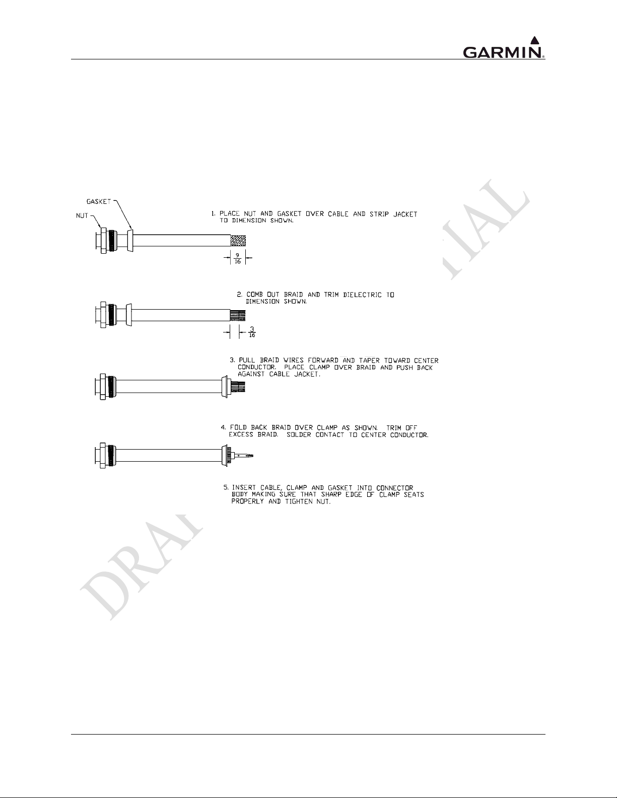
3.8 Cable Installation
Follow the steps below for installation of the coax cables:
1. Route the coaxial cable to the rack location keeping in mind the recommendations of Section 2.6.
Secure the cable in accordance with good aviation practice.
2. Trim the coaxial cable to the desired length and install the BNC connector (330-00087-00)
per the cabling instructions on Figure 3-1.. If the connector is provided by the installer, follow
the connector manufacturer’s instructions for cable preparation.
Figure 3-1. Coaxial Cable Installation
The card-edge connector may be used to terminate shield grounds to the GTN unit back plate.
Feed wires through the connector backshells before insertion into the 25-, 44-, and 78-pin connectors.
Contacts for the 25-, 44-, and 78-pin connectors must be crimped onto the individual wires of the aircraft
wiring harness. The following table lists contact part numbers (for reference). See Table 3-3 for
recommended crimp tools.
GTN 725/750 TSO Installation Manual Page 3-5
190-01007-02 Rev. A
Page 44
Table 3-4. Socket Contact Part Numbers
Configuration Module
Wire Gauge
Garmin P/N 336-00021-00 336-00021-00
Military P/N N/A M39029/58-360
AMP N/A 204370-2
Positronic N/A MC8522D
ITT Cannon N/A 010-2042-000
78-pin Connector (P1001)
28 AWG [1] 22-28 AWG [2]
P1001-P1005
Notes:
[1] For configuration module pins, ensure that the crimp tool is set to crimp 28 AWG wire
(indenter setting of ‘4’).
[2] Contacts listed are not to be used for configuration module wiring. Use the contacts
supplied with the configuration module when installing configuration module wires in
P1001.
Page 3-6 GTN 725/750 TSO Installation Manual
Rev. A 190-01007-02
Page 45

3.9 Equipment Mounting
3.9.1 Rack Installation
Use the dimensions shown in TBD to prepare the mounting holes for the GTN unit. You may also use the
GTN unit mounting rack itself as a template for drilling the mounting holes.
1. The back plate of the rack may optionally be removed for ease of mounting in the aircraft panel.
To do so, remove the two #4-40 screws, tilt the back plate away from the tray, and then slide the
back plate to the side.
2. TBD shows outline dimensions for the aviation rack for the various GTN units. Install the rack in
a rectangular 6.320” x 4.600” hole (or gap between units) in the instrument panel (see TBD). The
lower-front lip of the rack should be flush with, or extend slightly beyond, the finished aircraft
panel.
NOTE
If the front lip of the mounting rack is behind the surface of the aircraft panel, the
GTN unit connectors may not fully engage.
Make sure that no screw heads or other obstructions prevent the unit from fully engaging
in the rack (see the “Connector Engagement Test,” Section 5.3). Exercise caution when
installing the rack into the instrument panel. The rack is designed to facilitate removal of
the GTN unit for use in Demo Mode outside the aircraft. Deformation of the rack may
make it difficult to install and remove the GTN unit.
3. Install the rack in the aircraft panel using six #6-32 flat head screws and six self-locking nuts.
The screws are inserted from the inside through the holes in the sides of the rack.
4. If the back plate was previously removed (see Step 1), replace the back plate by positioning the
tabs on the back plate in the slots of the left side of the rack (viewing it from the cockpit) and
attaching it by replacing the two #4-40 screws.
3.9.2 GTN Unit Insertion and Removal
It may be necessary to insert the hex drive tool into the access hole and rotate the mechanism 90°
counterclockwise to insure correct position prior to placing the unit in the rack. The GTN unit is installed
in the rack by sliding it straight in until it stops, about 1 inch short of the final position. A 3/32-inch hex
drive tool is then inserted into the access hole at the bottom of the unit face. Rotate the hex tool clockwise
while pressing on the left side of the bezel until the unit is firmly seated in the rack.
To remove the unit from the rack, insert the hex drive tool into the access hole on the unit face and rotate
counterclockwise until the unit is forced out about 3/8 inches and can be freely pulled from the rack.
Be sure not to over tighten the unit into the rack. The application of hex drive tool torque exceeding
15 in-lbs can damage the locking mechanism.
3.9.3 Unit Replacement
Whenever the GTN unit is removed or reinstalled, verify that the unit power-up self-test sequence is
successfully completed and no failure messages are annunciated. Section TBD outlines the power-up selftest sequence.
GTN 725/750 TSO Installation Manual Page 3-7
190-01007-02 Rev. A
Page 46

3.10 Antenna Installation and Connections
3.10.1 GPS Antenna
This section provides information on the antenna cable installation. Refer to 0 herein for installation
location considerations.
NOTE
The internal GTN unit COM does not interfere with its own GPS receiver. However,
placement of the GTN unit antenna relative to other COM transceivers and antennas
(including the GTN unit COM antenna) is critical.
SUGGESTION: Temporarily locate the GPS antenna with coax connected to the GTN unit and check
the GPS performance as described in Section TBD and Section TBD. Once a suitable location has been
verified, then permanently mount the antenna.
Once the antenna mounting position has been prepared, route the coax cable from the antenna to the GTN
unit. Proper selection of coax cable and assembly of connectors is critical to GPS signal performance.
The cable loss from the GPS antenna shall be between 1.5 dB and 6.5 dB in order to maintain
proper rejection to interference signals.
The coaxial connectors and adapters, such as TNC to BNC, add additional loss to the cable and should be
considered when computing the cable loss. A typical loss of 0.2 dB can be used for each connection. To
maintain integrity of the WAAS signal, the GPS antenna coaxial cable must have a minimum of two
shields (e.g. RG-400 or RG-142B).
NOTE
If RG-142B or RG-400 is used, 1.5 dB equates to a length of approximately 6.5 feet of
cable with a connector on each end. RG-142B or RG-400 cable can be used as long as
the length is less than 35 feet. For longer lengths, use low-loss double or triple shielded
50Ω coax.
For very short runs, where the loss is less than 1.5 dB, additional cable should be used to increase the loss
to within 1.5 dB to 6.5 dB. This additional cable may be coiled, taking into account the minimum bend
radius of the cable.
During the post-installation checkout, susceptibility to harmonics of VHF COM transmitters will be
evaluated. If problems arise, then better isolation, or distance, may be required between the GPS and
COM antennas, or a 1575.42 MHz notch filter may be installed in series with the antenna coax of the
VHF COM transceiver to reduce or eliminate the harmonic interference. A notch filter for this use
(P/N 330-00067-00) is available from Garmin.
If a VHF COM transmitter causes problems with the GPS on the selected frequencies as listed in the postinstallation checkout, the problem may be due to the ELT. This can be verified by disconnecting the ELT
antenna coax at the ELT unit. If the ELT is found to cause the problem, then contact the ELT
manufacturer or replace the ELT.
Page 3-8 GTN 725/750 TSO Installation Manual
Rev. A 190-01007-02
Page 47

3.10.2 COM Antenna
The GTN unit requires a standard 50Ω vertically polarized antenna. Follow the antenna manufacturer’s
installation instructions for mounting the antenna.
The antenna should be mounted on a metal surface or a ground plane with a minimum area of
18 inches x 18 inches. Refer to Section 2.4.2 for installation location considerations.
The antenna coax cable should be made of RG-142B, RG-400 or a comparable quality 50Ω coax.
Check for insertion loss and VSWR (voltage standing wave ratio). VSWR should be checked with an inline type VSWR/wattmeter inserted in the coaxial transmission line between the transceiver and the
antenna. The VSWR should be inserted as close to the transceiver as possible. When rack and harness
buildup is performed in the shop, the coax termination may be provisioned by using a 6-inch inline BNC
connection. This would be an acceptable place to insert the VSWR. Any problem with the antenna
installation is most likely seen as high reflected power. A VSWR of 3:1 may result in up to a 50% loss in
transmit power.
3.10.3 NAV Antenna
The NAV antenna is a standard 50Ω horizontally polarized NAV/VOR/Localizer/Glideslope antenna (the
glideslope may be a separate antenna in some aircraft) that receives VOR frequencies between 108 and
117.95 MHz, and localizer frequencies between 108 and 112 MHz, and glideslope information between
328.6 and 335.4 MHz. Follow the antenna manufacturer’s installation instructions for mounting antennas.
It is recommended that the installer use RG-142B, RG-400 or equivalent 50Ω coax for the NAV
antenna(s).
The GTN has a single VOR/LOC/Glideslope input requiring some installations to use a standard external
diplexer or triplexer. See Section TBD.
GTN 725/750 TSO Installation Manual Page 3-9
190-01007-02 Rev. A
Page 48

This page intentionally left blank
Page 3-10 GTN 725/750 TSO Installation Manual
Rev. A 190-01007-02
Page 49

4. SYSTEM INTERCONNECTS
4.1 Pin Function List
4.1.1 P1001 Main Connector – Main Board
(View looking at rear of unit, Pin 1 is top right)
2
1
345678910111314151617181920
282930313233343536373839
27
47484950515253545556575859
46
676869707172737475767778
66
Pin Pin Name I/O
1 MAIN OBS ROTOR H (GND) -2 MAIN OBS ROTOR C Out
3 TIME MARK OUT A Out
4 AUDIO OUT HI Out
5 RS-232 OUT 4 Out
6 RS-232 OUT 3 Out
7 RS-232 OUT 2 Out
8 RS-232 OUT 1 Out
9 ARINC 429 OUT 2A Out
10 ARINC 429 OUT 1A Out
11 MAIN +TO OUT Out
12 MAIN VERTICAL +UP OUT Out
13 MAIN LATERAL SUPERFLAG OUT Out
14 OBS ANNUNCIATE* Out
15 GPS ANNUNCIATE* Out
16 OBS MODE SELECT* In
17 LIGHTING BUS 1 LO In
18 LIGHTING BUS 1 HI In
19 AIRCRAFT POWER In
20 AIRCRAFT POWER In
21 MAIN OBS STATOR D In
22 TIME MARK OUT B Out
23 AUDIO OUT LO Out
24 RS-232 IN 4 In
25 RS-232 IN 3 In
26 RS-232 IN 2 In
27 RS-232 IN 1 In
28 ARINC 429 OUT 2B Out
29 ARINC 429 OUT 1B Out
30 MAIN +FROM OUT Out
31 MAIN VERTICAL +DOWN OUT Out
32 MAIN VERTICAL SUPERFLAG OUT Out
33 WAYPOINT ANNUNCIATE* Out
34 TERMINAL ANNUNCIATE* Out
35 TAWS AUDIO ACTIVE OUT* Out
36 AUDIO INHIBIT IN* In
37 TAWS INHIBIT IN* In
38 AIR/GROUND* -39 CDI SOURCE SELECT* In
40 MAIN OBS STATOR E (GND) -41 MAIN OBS STATOR F In
2223242526
21
4041
42434445
636465
606162
GTN 725/750 TSO Installation Manual Page 4-1
190-01007-02 Rev. A
Page 50
P1001 Connector Cont’d
Pin Pin Name I/O
42 LIGHTING BUS 2 LO In
43 FAN GROUND -44 RS-232 GND 3/4 -45 RS-232 GND 2 -46 RS-232 GND 1 -47 ARINC 429 IN 2A In
48 ARINC 429 IN 1A In
49 MAIN LATERAL +LEFT OUT Out
50 MAIN LATERAL +FLAG OUT Out
51 MAIN VERTICAL +FLAG OUT Out
52 VLOC ANNUNCIATE* Out
53 LOI ANNUNCIATE* Out
54 MESSAGE ANNUNCIATE* Out
55 APPROACH ANNUNCIATE* Out
56 ILS/GPS APPROACH Out
57 TAWS INHIBIT ANNUNCIATE* Out
58 FAN TACH IN In
59 FAN POWER OUT (12 VDC) Out
60 MAIN OBS STATOR G (GND) -61 LIGHTING BUS 2 HI In
62 CONFIG MODULE DATA I/O
63 CONFIG MODULE CLOCK Out
64 CONFIG MODULE GND Out
65 CONFIG MODULE POWER Out
66 ARINC 429 IN 2B In
67 ARINC 429 IN 1B In
68 MAIN LATERAL +RIGHT OUT Out
69 MAIN LATERAL -FLAG OUT Out
70 MAIN VERTICAL -FLAG OUT Out
71 TERRAIN WARNING ANNUNCIATE* Out
72 TERRAIN NOT AVAILABLE ANNUNCIATE* Out
73 TERRAIN CAUTION ANNUNCIATE* Out
74 GPS SELECT* Out
75 TRAFFIC TEST* Out
76 TRAFFIC STANDBY* Out
77 AIRCRAFT GND -78 AIRCRAFT GND --
Page 4-2 GTN 725/750 TSO Installation Manual
Rev. A 190-01007-02
Page 51
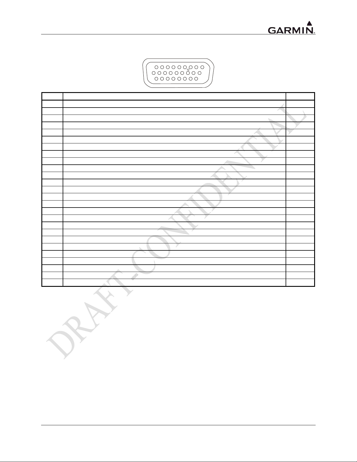
4.1.2 P1002 Connector
(View looking at rear of unit, Pin 1 is top right)
123456789
131415161718
2223242526
Pin Pin Name I/O
1 DEMO MODE SELECT* In
2 RESERVED In
3 SPARE DISC OUT A* Out
4 ETHERNET OUT 4A Out
5 ETHERNET OUT 4B Out
6 ETHERNET IN 1A In
7 ETHERNET IN 1B In
8 ETHERNET OUT 1A Out
9 ETHERNET OUT 1B Out
10 SYSTEM ID PROGRAM* In
11 SPARE DISC IN D* In
12 SPARE DISC OUT B* Out
13 ETHERNET IN 4A In
14 ETHERNET IN 4B In
15 ETHERNET IN 2A In
16 ETHERNET IN 2B In
17 ETHERNET OUT 2A Out
18 ETHERNET OUT 2B Out
19 RS-422 IN A In
20 RS-422 IN B In
21 RS-422 OUT A Out
22 RS-422 OUT B Out
23 ETHERNET IN 3A In
24 ETHERNET IN 3B In
25 ETHERNET OUT 3A Out
26 ETHERNET OUT 3B Out
1011
21
1920
GTN 725/750 TSO Installation Manual Page 4-3
190-01007-02 Rev. A
Page 52

4.1.3 P1003 COM Connector
(View looking at rear of unit, Pin 1 is top right)
1234567891011131415
282930
27
4041
424344
Pin Pin Name I/O
1 RESERVED Out
2 RESERVED In
3 AUX AUDIO LINE LEVEL HI (function not currently implemented) In
4 AUX AUDIO SIGNAL LEVEL HI (function not currently implemented) In
5 COM MIC 1 AUDIO IN HI In
6 COM MIC 2 AUDIO IN HI (function not currently implemented) In
7 500 Ω COM AUDIO HI Out
8 RESERVED In
9 RESERVED In
10 RESERVED In
11 COM MIC 1 KEY* In
12 INTERCOM ENABLE* (function not currently implemented) In
13 SPEAKER OUT (function not currently implemented) Out
14 RESERVED In
15 RESERVED Out
16 RESERVED In
17 RESERVED In
18 500 Ω COM AUDIO LO -19 AUX AUDIO LINE LEVEL GND (function not currently implemented) -20 MIC AUDIO IN LO In
21 AUX AUDIO SIGNAL LEVEL GND (function not currently implemented) --
22 RESERVED In
23 RESERVED Out
24 RESERVED Out
25 RESERVED Out
26 COM MIC 2 KEY* (function not currently implemented) In
27 COM REMOTE TRANSFER* In
28 COM REMOTE TUNE UP* In
29 COM REMOTE TUNE DOWN* In
30 AIRCRAFT POWER In
31 RESERVED -32 RESERVED In
33 RESERVED Out
34 RESERVED -35 RESERVED Out
36 RESERVED -37 AIRCRAFT GND -38 AIRCRAFT GND -39 SPEAKER GND (function not currently implemented) --
40 AIRCRAFT GND -41 RESERVED In
42 RESERVED In
43 AIRCRAFT POWER In
44 AIRCRAFT POWER In
2223242526
21
1617181920
313233343536373839
Page 4-4 GTN 725/750 TSO Installation Manual
Rev. A 190-01007-02
Page 53

4.1.4 P1004 NAV Connector
(View looking at rear of unit, Pin 1 is on bottom left)
58575655545352515049484746
454443
2423
22
1234567891011 13 14 15 16 17 18 19 20
59
363534333231302928272625
37
626160
4241403938
21
Pin Pin Name I/O
1 VOR/LOC +TO Out
2 VOR/LOC +FROM Out
3 VOR/LOC +FLAG Out
4 VOR/LOC -FLAG Out
5 VOR/LOC +LEFT Out
6 VOR/LOC +RIGHT Out
7 RESERVED Out
8 VOR/LOC COMPOSITE OUT Out
9 VOR OBS ROTOR C Out
10 VOR OBS ROTOR H (GND) Out
11 VOR OBS STATOR E (GND) Out
12 VOR OBS STATOR F In
13 VOR OBS STATOR D In
14 VOR OBS STATOR G (GND) Out
15 VOR/LOC SUPERFLAG Out
16 500 Ω VOR/LOC AUDIO OUT HI Out
17 500 Ω VOR/LOC AUDIO OUT LO Out
18 SERIAL DME - CLOCK In/Out
19 SERIAL DME - DATA In/Out
20 SERIAL DME- RNAV/CH REQ In
21 SERIAL DME - RNAV MODE In
22 AIRCRAFT GND -23 VOR/ILS ARINC 429 OUT B Out
24 VOR/ILS ARINC 429 OUT A Out
25 VOR OBI CLOCK In
26 VOR OBI SYNC In
27 VOR OBI DATA In
28 VLOC REMOTE TRANSFER In
29 ILS ENERGIZE Out
30 RESERVED -31 RESERVED -32 GLIDESLOPE +FLAG Out
33 PAR DME 1MHZ-D/SERIAL DME ON Out
34 GLIDESLOPE +UP Out
35 VOR/ILS ARINC 429 IN B In
36 VOR/ILS ARINC 429 IN A In
37 PAR DME 100KHZ-A/SERIAL DME HOLD Out
38 GLIDESLOPE SUPERFLAG Out
39 PAR DME 100KHZ-B Out
40 PAR DME 100KHZ-C Out
41 DME COMMON In
42 PAR DME 100KHZ-D Out
43 PAR DME 50KHZ Out
44 SERIAL DME - DME REQUEST In/Out
45 PAR DME 1MHZ-A Out
46 PAR DME 1MHZ-B Out
GTN 725/750 TSO Installation Manual Page 4-5
190-01007-02 Rev. A
Page 54

P1004 Connector Cont’d
Pin Pin Name I/O
47 PAR DME 1MHZ-C Out
48 RESERVED -49 AIRCRAFT GND -50 RESERVED -51 AIRCRAFT POWER In
52 AIRCRAFT POWER In
53 GLIDESLOPE -FLAG Out
54 PAR DME 100KHZ-E Out
55 GLIDESLOPE +DOWN Out
56 PAR DME 1MHZ-E Out
57 RESERVED -58 GLIDESLOPE COMPOSITE OUT Out
59 VOR/LOC DIGITAL AUDIO OUT Out
60 AIRCRAFT GND -61 AIRCRAFT GND -62 AIRCRAFT GND --
Page 4-6 GTN 725/750 TSO Installation Manual
Rev. A 190-01007-02
Page 55

4.2 I/O Board
4.2.1 P1005 Connector
(View looking at rear of unit, Pin 1 is on bottom left)
58575655545352515049484746
454443
2423
22
1234567891011 13 14 15 16 17 18 19 20
59
363534333231302928272625
37
626160
4241403938
21
Pin Pin Name I/O
1 VIDEO INPUT 2 (function not currently implemented) In
2 VIDEO INPUT 1 (function not currently implemented) In
3 RESERVED --
4 RESERVED --
5 RESERVED --
6 RESERVED --
7 ARINC 429 OUT 3B Out
8 RS-232 OUT 5 Out
9 RS-232 OUT 6 Out
10 RS-485 2A/422 OUT 1 (function not currently implemented) Out
11 RS-485 2B/422 OUT 2 (function not currently implemented) Out
12 RESERVED -13 WX RADAR ON* (function not currently implemented) Out
14 SYNCHRO Y In
15 SYNCHRO REF LO In
16 ARINC 429 IN 3B In
17 ARINC 429 IN 4B In
18 ARINC 453/708 IN 1A (function not currently implemented) In
19 ARINC 453/708 TERM 1B (function not currently implemented) In
20 ARINC 453/708 IN 2A (function not currently implemented) In
21 ARINC 453/708 TERM 2B (function not currently implemented) In
22 VIDEO INPUT 2 GND (function not currently implemented) In
23 VIDEO INPUT 1 GND (function not currently implemented) In
24 RESERVED -25 RESERVED -26 RESERVED -27 RESERVED -28 ARINC 429 OUT 3A Out
29 RS-232 IN 5 In
30 RS-232 IN 6 In
31 RS-485 1A/422 IN 1 (function not currently implemented) In
32 RS-485 1B/422 IN 2 (function not currently implemented) In
33 SYNCHRO VALID INPUT (ACTIVE LO) In
34 SPARE OUTPUT C Out
35 SYNCHRO X In
36 SYNCHRO REF HIGH In
37 ARINC 429 IN 3A In
38 ARINC 429 IN 4A In
39 RESERVED -40 ARINC 453/708 TERM 1A (function not currently implemented) In
41 RESERVED -42 ARINC 453/708 TERM 2A (function not currently implemented) In
43 RESERVED -44 RESERVED --
GTN 725/750 TSO Installation Manual Page 4-7
190-01007-02 Rev. A
Page 56

P1005 Connector Cont’d
Pin Pin Name I/O
45 RESERVED -46 RESERVED -47 RESERVED -48 RESERVED -49 RS-232 GND 5 -50 RS-232 GND 6 -51 RESERVED -52 RESERVED -53 SPARE INPUT 1 In
54 SYNCHRO VALID INPUT (ACTIVE HI) -55 RESERVED -56 SYNCHRO Z In
57 RESERVED -58 RESERVED -59 RESERVED -60 ARINC 453/708 IN 1B (function not currently implemented) In
61 RESERVED -62 ARINC 453/708 IN 2B (function not currently implemented) In
Page 4-8 GTN 725/750 TSO Installation Manual
Rev. A 190-01007-02
Page 57
4.3 Power, Lighting, And Antennas
This section covers the power input requirements, lighting bus input, and antenna connections.
See Figure TBD for interconnect information.
4.3.1 Power
Pin Name Connector Pin I/O
AIRCRAFT POWER (MAIN) P1001 19 In
AIRCRAFT POWER (MAIN) P1001 20 In
AIRCRAFT POWER (COM) P1003 30 In
AIRCRAFT POWER (COM) P1003 43 In
AIRCRAFT POWER (COM) P1003 44 In
AIRCRAFT POWER (NAV) P1004 51 In
AIRCRAFT POWER (NAV) P1004 52 In
AIRCRAFT GROUND (MAIN) P1001 77 -AIRCRAFT GROUND (MAIN) P1001 78 -AIRCRAFT GROUND (COM) P1003 37 -AIRCRAFT GROUND (COM) P1003 38 -AIRCRAFT GROUND (COM) P1003 40 -AIRCRAFT GROUND (NAV) P1004 61 -AIRCRAFT GROUND (NAV) P1004 62 --
The power inputs P1001-19 and P1001-20 provide power for everything except for the COM radio and
NAV radio. Both pins must be connected.
The power inputs P1003-30, P1003-43, and P1003-44 provide power for the COM radio. All three pins
must be connected.
The power inputs P1004-51 and P1004-52 provide power for the NAV radio. Both pins must be
connected.
4.3.2 Lighting Bus
Pin Name Connector Pin I/O
LIGHTING BUS 1 HI P1001 18 In
LIGHTING BUS 1 LO P1001 17 In
LIGHTING BUS 2 HI P1001 42 In
LIGHTING BUS 2 LO P1001 61 In
The GTN can be configured to track 28 VDC, 14 VDC, 5 VDC or 5 VAC lighting buses using these
inputs. Two lighting buses allow for independent control of display and bezel lighting. Alternatively, the
GTN can automatically adjust for ambient lighting conditions based on the photocell. Refer to Section
TBD for instructions on configuring the lighting inputs.
4.3.3 Antennas
Pin Name Connector I/O
GPS/WAAS ANTENNA P1006 In
COM ANTENNA P1007 I/O
NAV ANTENNA P1008 In
The GPS/WAAS, COM, and NAV antennas use BNC coaxial connectors on the connector backplate.
Reference Figure TBD for splitter/diplexer block diagrams.
GTN 725/750 TSO Installation Manual Page 4-9
190-01007-02 Rev. A
Page 58

4.3.4 Serial Data
4.3.4.1 Serial Data Function
4.3.4.1.1 RS-232
The GTN is capable of interfacing with other aviation instruments by transmitting RS-232 Type 1 (often
known as ARNAV format) and Type 2 (often known as Northstar format) data on any RS-232 OUT port.
The data consists of the following (refer to Section B.1 for a detailed data format description):
• Current latitude, longitude, and GPS altitude in feet (see Note below)
• Current velocity vector (ground speed and direction of velocity vector over the ground)
• Distance to waypoint
• Cross track error
• Desired track
• Destination waypoint identifier
• Bearing to destination waypoint
• Magnetic variation
• Navigation and warning status
• Waypoint sequence in route
• Waypoint position (latitude and longitude) and magnetic variation
NOTE
Aviation RS-232 data may be transmitted with or without the current GPS altitude in feet.
Refer to Appendix B.
The GTN can receive pressure altitude, air data, and fuel data from certain systems on any RS-232 IN port.
If a GTN is installed with a 400W or 500W Series in an aircraft, any of the RS-232 ports on the GTN may
be cross-connected to RS-232 Port 3 on the GTN to manually transfer user-defined waypoints between
the two units.
Page 4-10 GTN 725/750 TSO Installation Manual
Rev. A 190-01007-02
Page 59
4.3.4.1.2 ARINC 429
The data output on the ARINC 429 OUT ports depends on the configuration (see Section TBD). Below is
a list of the configurations and the labels output for each one:
• ARINC 429
• GAMA 429
• GAMA 429 Graphics
• GAMA 429 Graphics w/Int
• GAMA 429 Pro Line 21
• GAMA 429 Sextant
• GAMA 429 Bendix King
Label # Parameter Name 1 2 3 4 5 6 7
001 Distance to Go (BCD) ● ● ● ● ● ● ●
002 Time to Go (BCD) ● ● ● ● ● ● ●
012 Ground Speed (BCD) ● ● ● ● ● ● ●
074G Data Record Header ● ● ● ● ● ●
075G Active Wpt From/To Data ● ● ● ● ● ●
100 Selected Course 1 ●
100P Selected Course 1 ● ● ● ● ● ●
113G Message Checksum ● ● ● ● ● ●
114 Desired Track (True) ● ● ● ● ● ● ●
115 Waypoint Bearing (True) ● ● ● ● ● ● ●
116 Cross Track Distance ●
116G [1] Cross Track Distance ● ● ● ● ● ●
117G Vertical Deviation ● ● ● ● ●
117P Vertical Deviation ●
121 Horizontal Command (to Autopilot) ● ● ● ● ● ● ●
125 Greenwich Mean Time (BCD) ● ● ● ● ● ● ●
147G Magnetic Variation ● ● ● ● ● ●
251 Distance to Go ●
251G Distance to Go ● ● ● ● ● ●
252 Time to Go ● ● ● ● ● ● ●
260G Date (BCD) ● ● ● ● ● ●
261G GPS Discrete Word 1 ● ● ● ● ● ●
275G LRN Status Word ● ● ● ● ● ●
300G Station Declination, Type, and Class ● ● ● ● ● ●
303 Message Length/Type/Number ● ● ● ● ● ●
304G Message Characters 1-3 ● ● ● ● ● ●
305G Message Characters 4-6 ● ● ● ● ● ●
306G NAV/Waypoint/Airport Latitude ● ● ● ● ● ●
307G NAV/Waypoint/Airport Longitude ● ● ● ● ● ●
310 Present Position Latitude ● ● ● ● ● ● ●
311 Present Position Longitude ● ● ● ● ● ● ●
312 Ground Speed ● ● ● ● ● ● ●
313 Track Angle (True) ● ● ● ● ● ● ●
314 True Heading ● ● ● ● ● ● ●
315 Wind Speed ● ● ● ● ● ● ●
316 Wind Angle (True) ● ● ● ● ● ● ●
320 Magnetic Heading ● ● ● ● ● ● ●
GTN 725/750 TSO Installation Manual Page 4-11
190-01007-02 Rev. A
Page 60
Label # Parameter Name 1 2 3 4 5 6 7
321 Drift Angle ● ● ● ● ● ● ●
326G [1] Lateral Scale Factor ● ● ● ● ● ●
327G Vertical Scale Factor ● ● ● ● ●
330 Conic Arc Inbound Course ● ●
331 Conic Arc Radius ● ●
332 Conic Arc Course Change Angle ● ●
333 Airport Runway Azimuth ● ●
334 Airport Runway Length in Feet ● ●
335 Left/Right Hand Holding Pattern Azimuth ● ●
340 Left/Right Hand Procedure Turn Azimuth ● ●
351G Distance to Destination (Via Flight Plan) ● ● ● ● ● ●
352G Estimated Time to Destination (Via Flight Plan) ● ● ● ● ● ●
371G Specific Equipment ID ● ● ● ● ● ●
377 Equipment Hex ID Code ● ● ● ● ● ● ●
[1] Label 116G and 326G utilize the optional resolution extension bits (bits 11-13).
The following labels are output on the VOR/ILS ARINC 429 OUT port:
Label # Parameter Name
034G VOR/ILS Frequency (BCD)
035G DME Frequency (BCD)
100G Selected Course #1
173 Localizer Deviation
174 Glideslope Deviation
222 VOR Omnibearing
371G Specific Equipment ID
377 Equipment Hex ID Code
The labels recognized on the ARINC 429 IN ports depend on the configuration (see Section TBD).
4.3.4.1.3 ARINC 453/708
The GTN can receive ARINC 453/708 weather radar data from specific weather radars. For more
information, refer to Section TBD.
Page 4-12 GTN 725/750 TSO Installation Manual
Rev. A 190-01007-02
Page 61
4.3.4.2 Serial Data Electrical Characteristics
4.3.4.2.1 RS-232
Pin Name Connector Pin I/O
RS-232 OUT 1 P1001 8 Out
RS-232 IN 1 P1001 27 In
RS-232 GND 1 P1001 46 -RS-232 OUT 2 P1001 7 Out
RS-232 IN 2 P1001 26 In
RS-232 GND 2 P1001 45 -RS-232 OUT 3 P1001 6 Out
RS-232 IN 3 P1001 25 In
RS-232 GND 3 P1001 44 -RS-232 OUT 4 P1001 5 Out
RS-232 IN 4 P1001 24 In
RS-232 GND 4 P1001 43 -RS-232 OUT 5 P1005 8 Out
RS-232 IN 5 P1005 29 In
RS-232 GND 5 P1005 49 -RS-232 OUT 6 P1005 9 Out
RS-232 IN 6 P1005 30 In
RS-232 GND 6 P1005 50 --
The RS-232 outputs are compatible with EIA Standard RS-232C with an output voltage swing of at least
±5 V when driving a standard RS-232 load.
4.3.4.2.2 ARINC 429
Pin Name Connector Pin I/O
ARINC 429 OUT 1A P1001 10 Out
ARINC 429 OUT 1B P1001 29 Out
ARINC 429 OUT 2A P1001 9 Out
ARINC 429 OUT 2B P1001 28 Out
ARINC 429 IN 1A P1001 48 In
ARINC 429 IN 1B P1001 67 In
ARINC 429 IN 2A P1001 47 In
ARINC 429 IN 2B P1001 66 In
VOR/ILS ARINC 429 OUT A P1004 24 Out
VOR/ILS ARINC 429 OUT B P1004 23 Out
VOR/ILS ARINC 429 IN A P1004 36 In
VOR/ILS ARINC 429 IN B P1004 35 In
ARINC 429 OUT 3A P1005 28 Out
ARINC 429 OUT 3B P1005 7 Out
ARINC 429 IN 3A P1005 37 In
ARINC 429 IN 3B P1005 16 In
ARINC 429 IN 4A P1005 38 In
ARINC 429 IN 4B P1005 17 In
The ARINC 429 outputs conform to ARINC 429 electrical specifications when loaded with up to five
standard ARINC 429 receivers.
GTN 725/750 TSO Installation Manual Page 4-13
190-01007-02 Rev. A
Page 62
4.3.4.2.3 RS-422
The RS-422 port is provisional; no RS-422 interfaces are currently supported.
Pin Name Connector Pin I/O
RS-422 IN A P1002 19 In
RS-422 IN B P1002 20 In
RS-422 OUT A P1002 21 Out
RS-422 OUT B P1002 22 Out
The RS-422 ports are compatible with EIA Standard RS-422 with a differential output voltage swing of at
least ±1.5V when driving a standard RS-422 load.
4.3.4.2.4 RS-422/RS-485
The RS-422/RS-485 ports are provisional; no RS-422 or RS-485 interfaces are currently supported.
Pin Name Connector Pin I/O
RS-485 1A/422 IN 1 P1005 31 I/O
RS-485 1B/422 IN 2 P1005 32 I/O
RS-485 2A/422 OUT 1 P1005 10 I/O
RS-485 2B/422 OUT 2 P1005 11 I/O
The RS-422/485 ports are compatible with EIA Standard RS-485 (RS-422 when configured as RS-422)
with a differential output voltage swing of at least ±1.5V when driving a standard RS-422/485 load.
4.3.4.2.5 ARINC 453/708
Pin Name Connector Pin I/O
ARINC 453/708 IN 1A P1005 18 In
ARINC 453/708 IN 1B P1005 60 In
ARINC 453/708 TERM 1A P1005 40 -ARINC 453/708 TERM 1B P1005 19 -ARINC 453/708 IN 2A P1005 20 In
ARINC 453/708 IN 2B P1005 62 In
ARINC 453/708 TERM 2A P1005 42 -ARINC 453/708 TERM 2B P1005 21 --
The ARINC 453/708 port 1 is compatible with specific weather radar units. If the GTN is the only
receiver or if it is the last receiver in a chain of receivers, a jumper should be installed between P1005-40
and P1005-19 for port 1. This jumper adds resistance of approximately 75Ω between P1005-18 and
P1005-60.
Page 4-14 GTN 725/750 TSO Installation Manual
Rev. A 190-01007-02
Page 63
4.3.5 Ethernet (HSDB)
Pin Name Connector Pin I/O
ETHERNET OUT 1 A P1002 8 Out
ETHERNET OUT 1 B P1002 9 Out
ETHERNET IN 1 A P1002 6 In
ETHERNET IN 1 B P1002 7 In
ETHERNET OUT 2 A P1002 17 Out
ETHERNET OUT 2 B P1002 18 Out
ETHERNET IN 2 A P1002 15 In
ETHERNET IN 2 B P1002 16 In
ETHERNET OUT 3 A P1002 25 Out
ETHERNET OUT 3 B P1002 26 Out
ETHERNET IN 3 A P1002 23 In
ETHERNET IN 3 B P1002 24 In
ETHERNET OUT 4 A P1002 4 Out
ETHERNET OUT 4 B P1002 5 Out
ETHERNET IN 4 A P1002 13 In
ETHERNET IN 4 B P1002 14 In
The Ethernet-based HSDB (High Speed Data Bus) meets the hardware aspects of IEEE standard 802.3 for
10 base T Ethernet communications.
4.3.6 Main Audio Output
The main audio output is used to play the ‘clicks’ associated with the touch screen, as well as TAWS
alerts on GTN units that are equipped with TAWS.
Pin Name Connector Pin I/O
AUDIO OUT HI P1001 4 Out
AUDIO OUT LO P1001 23 Out
The audio output will be 80 mW across a 500Ω load.
GTN 725/750 TSO Installation Manual Page 4-15
190-01007-02 Rev. A
Page 64
4.3.7 Main Indicator
4.3.7.1 Main Indicator Function
The Main Indicator displays both lateral and vertical deviation from selected course, To/From indications,
lateral and vertical flags and superflags.
The “CDI” button on the screen of the GTN takes the place of remote “NAV/GPS” switches, and is used
to toggle between display of GPS and VOR/ILS navigation on a remote indicator. The navigation source
is annunciated on the display below the ‘CDI’ button. The navigation method is optionally annunciated
externally by connecting to the VLOC ANNUNCIATE output (P1001-52) and GPS ANNUNCIATE
output (P1001-15). GPS and VOR/ILS navigation may be toggled externally when the CDI SOURCE
SELECT input (P1001-39) is momentarily grounded. See Section TBD and TBD for more information
on the discrete inputs and outputs.
An OBS resolver connection to the GPS is preferred, but not required. For the GTN 650 and GTN 750,
an OBS resolver typically is connected to the MAIN OBS inputs for use with the VOR receiver.
4.3.7.2 Main Indicator Electrical Characteristics
4.3.7.2.1 Deviation
Pin Name Connector Pin I/O
MAIN LATERAL +LEFT OUT P1001 49 Out
MAIN LATERAL +RIGHT OUT P1001 68 Out
MAIN VERTICAL +UP OUT P1001 12 Out
MAIN VERTICAL +DOWN OUT P1001 31 Out
The deviation output is capable of driving up to three 1000Ω meter loads with ±150 mVDC ±10% for
full-scale deflection. The drive circuit provides for more than full-scale deflection with a maximum
course deviation output voltage of ±300 mVDC ±10%.
4.3.7.2.2 TO/FROM
Pin Name Connector Pin I/O
MAIN +TO OUT P1001 11 Out
MAIN +FROM OUT P1001 30 Out
The output is capable of driving up to three 200Ω meter loads. When indicating TO, MAIN +TO OUT is
+225 ±75 mV DC with respect to MAIN +FROM OUT. When indicating FROM, MAIN +TO OUT is 225 ±75 mV DC with respect to MAIN +FROM OUT. When invalid information is present (Flag IN
VIEW) the TO/FROM output is 0 ±20 mV DC.
4.3.7.2.3 Flags
Pin Name Connector Pin I/O
MAIN LATERAL +FLAG OUT P1001 50 Out
MAIN LATERAL -FLAG OUT P1001 69 Out
MAIN VERTICAL +FLAG OUT P1001 51 Out
MAIN VERTICAL -FLAG OUT P1001 70 Out
The Flag outputs are capable of driving up to three 1000Ω meter loads. When valid information is present
(Flag OUT OF VIEW) the Flag output is 375 ±80 mV DC. When invalid information is present (Flag IN
VIEW) the Flag output is 0 ±25 mV DC.
Page 4-16 GTN 725/750 TSO Installation Manual
Rev. A 190-01007-02
Page 65
4.3.7.2.4 Superflags
Pin Name Connector Pin I/O
LATERAL SUPERFLAG OUT P1001 13 Out
MAIN VERTICAL SUPERFLAG OUT P1001 32 Out
The output supplies not less than 400 mA with the output voltage not less than (AIRCRAFT POWER –
2.0 VDC) when the flag is to be OUT OF VIEW. The output is electrically open when the flag is to be
IN VIEW.
4.3.8 OBS
Pin Name Connector Pin I/O
MAIN OBS ROTOR C P1001 2 Out
MAIN OBS ROTOR H (GND) P1001 1 -MAIN OBS STATOR D P1001 21 In
MAIN OBS STATOR E (GND) P1001 40 -MAIN OBS STATOR F P1001 41 In
MAIN OBS STATOR G (GND) P1001 60 --
MAIN OBS ROTOR C and H (GND) are a buffered output that is intended to drive the OBS rotors.
MAIN OBS STATOR D and MAIN OBS STATOR F are each phase and amplitude shifted version of the
MAIN ROTOR C output. Each pair is intended to read one of the two windings of the indicator’s OBS
stator.
4.3.9 Discrete Inputs
Pin Name Connector Pin I/O
OBS MODE SELECT* P1001 16 In
AUDIO INHIBIT IN* P1001 36 In
TAWS INHIBIT IN* P1001 37 In
AIR/GROUND* P1001 38 In
CDI SOURCE SELECT* P1001 39 In
DEMO MODE SELECT* P1002 1 In
SYSTEM ID PROGRAM* P1002 10 In
SPARE DISC IN D* P1002 11 In
RESERVED P1005 12 In
SYNCHRO VALID INPUT (ACTIVE LO) P1005 33 In
An asterisk (*) following a signal name denotes that the signal is Active-Low, requiring a ground to
activate. If there is no asterisk, the signal is Active-High.
Active-low discrete inputs are considered active if either the voltage to ground is ≤3.5 VDC or the
resistance to ground is ≤375Ω. These inputs are considered inactive if the voltage to ground is
6.5-33 VDC or the resistance to ground is >100 kΩ.
Active-high discrete inputs are considered active if either the voltage to ground is >6.5 VDC. These
inputs are considered inactive if the voltage to ground is ≤3.5 VDC or the resistance to ground is
≤375Ω.
4.3.9.1 OBS MODE SELECT*
The OBS MODE SELECT discrete input may be used to toggle between GPS OBS and GPS AUTO
modes of operation. A momentary low on this pin performs the same function as pressing the ‘OBS’
button on the GTN display.
GTN 725/750 TSO Installation Manual Page 4-17
190-01007-02 Rev. A
Page 66
4.3.9.2 AUDIO INHIBIT IN*
The AUDIO INHIBIT IN discrete input may be used to suppress TAWS and touch screen feedback audio
from the GTN.
4.3.9.3 TAWS INHIBIT IN*
The TAWS INHIBIT IN discrete input, when toggled momentarily low, may be used to inhibit TAWS
alerts from the GTN.
4.3.9.4 AIR/GROUND*
The AIR/GROUND discrete input may be used to control the air/ground status of the GTN.
4.3.9.5 CDI SOURCE SELECT* (GTN 750 only)
The CDI SOURCE SELECT discrete input may be used to toggle between display of GPS and
VOR/LOC/Glideslope information on the MAIN external CDI/HSI. A momentary low on this pin
performs the same function as pressing the ‘CDI’ button on the GTN display.
4.3.9.6 DEMO MODE SELECT*
The DEMO MODE SELECT discrete input may be used to select Demo Mode on the GTN. When this
pin is connected to ground during power up, the GTN starts up in Demo Mode. Demo Mode allows the
GTN to simulate reception of GPS satellite signals.
CAUTION
Do not connect DEMO MODE SELECT in an aircraft installation.
NOTE
Demo Mode can also be accessed by holding down the D button during power-up.
4.3.9.7 SYSTEM ID PROGRAM*
The System ID PROGRAM discrete input is used to identify the #2 unit in an installation with more than
one GTN. This input must be strapped to ground on the second GTN.
SYSTEM ID PROGRAM* GTN Installation
Open GTN #1 or single-GTN installation
Ground GTN #2
4.3.9.8 SYNCHRO VALID INPUT
There are two SYNCHRO VALID INPUTs; one is active-high and the other is active-low. Unless one of
the two input is active, the GTN considers the synchro heading input to be invalid.
Page 4-18 GTN 725/750 TSO Installation Manual
Rev. A 190-01007-02
Page 67
4.3.10 Discrete Outputs
Pin Name Connector Pin I/O
OBS ANNUNCIATE* P1001 14 Out
GPS ANNUNCIATE* P1001 15 Out
WAYPOINT ANNUNCIATE* P1001 33 Out
TERMINAL ANNUNCIATE* P1001 34 Out
TAWS AUDIO ACTIVE OUT P1001 35 Out
VLOC ANNUNCIATE* P1001 52 Out
LOI ANNUNCIATE* P1001 53 Out
MESSAGE ANNUNCIATE* P1001 54 Out
APPROACH ANNUNCIATE* P1001 55 Out
ILS/GPS APPROACH* P1001 56 Out
TAWS INHIBIT ANNUNCIATE* P1001 57 Out
TERRAIN WARNING ANNUNCIATE* P1001 71 Out
TERRAIN NOT AVAILABLE ANNUNCIATE* P1001 72 Out
TERRAIN CAUTION ANNUNCIATE* P1001 73 Out
GPS SELECT* [1] P1001 74 Out
TRAFFIC TEST* P1001 75 Out
TRAFFIC STANDBY* P1001 76 Out
SPARE DISC OUT A* P1002 3 Out
SPARE DISC OUT B* P1002 12 Out
WX RADAR ON* (function not currently implemented) P1005 13 Out
SPARE OUTPUT C* P1005 34 Out
[1] The operation of the GPS SELECT can be configured.
An asterisk (*) following a signal name denotes that the signal is Active-Low, producing a low (ground)
on the output when active.
All discrete outputs from the GTN are Active-Low. Each is an “open drain” output capable of sinking 500
mA when active.
4.3.10.1 OBS ANNUNCIATE*
The OBS ANNUNCIATE output is driven to indicate GPS OBS mode of operation. This output is active
when the OBS or SUSP annunciation is on the display.
4.3.10.2 GPS ANNUNCIATE* (GTN 750 Only)
The GPS ANNUNCIATE output is driven when the unit is configured with a single CDI/HSI and the
GPS data is being displayed on the CDI/HSI. This output parallels the GPS annunciation on the display.
4.3.10.3 WAYPOINT ANNUNCIATE*
The WAYPOINT ANNUNCIATE output is driven in the following manner:
1. When the aircraft is within 10 seconds of reaching the turning point for a course change, the
waypoint annunciator flashes.
2. When the aircraft is in a turn, the waypoint annunciator illuminates and remains illuminated until
the turn is completed.
3. When a user arrival alarm is set and the aircraft is within the circle defined by the arrival alarm
radius at the arrival waypoint, the waypoint annunciator flashes for 10 seconds.
4. When a user arrival alarm is not set and the aircraft is within 10 seconds of reaching the arrival
waypoint, the waypoint annunciator flashes.
GTN 725/750 TSO Installation Manual Page 4-19
190-01007-02 Rev. A
Page 68

4.3.10.4 TERMINAL ANNUNCIATE*
When performing approach navigation, the TERMINAL ANNUNCIATE output is active when operating
within 30 nautical miles of the departure or arrival airport and the CDI scale is the equivalent or 1.0 nm or
less.
4.3.10.5 TAWS AUDIO ACTIVE OUT*
The TAWS AUDIO ACTIVE OUT is active when the GTN is playing a TAWS alert. This output can be
connected to the Audio Inhibit input of other units with audio that is lower priority than TAWS.
4.3.10.6 VLOC ANNUNCIATE* (GTN 750 Only)
The VLOC ANNUNCIATE output is driven when the unit is configured with a single CDI/HSI and the
VOR/ILS data is being displayed on the CDI/HSI. This output parallels the VLOC annunciator on the
display.
4.3.10.7 LOI ANNUNCIATE*
The LOI ANNUNCIATE output is active when the GPS receiver detects a position error, or is unable to
calculate the integrity of the position. On the 400W/500W Series navigators, this output was called
‘Integrity Annunciate’.
4.3.10.8 MESSAGE ANNUNCIATE*
When a new status message is available, the MESSAGE ANNUNCIATE output is active and the
message annunciator flashes. When status messages remain effective, the message annunciator
illuminates continuously.
4.3.10.9 APPROACH ANNUNCIATE*
When performing approach navigation, the APPROACH ANNUNCIATE output is active while an
approach is active.
4.3.10.10 ILS/GPS APPROACH*
The ILS/GPS APPROACH output is active when:
• GPS navigation is selected and either a GPS approach mode is active or 0.3 nm is selected for the
CDI full scale deflection; or
• VLOC navigation is selected and an ILS channel has been selected.
This output may be connected to the ILS Engage input of an autopilot or flight director to provide higher
autopilot gain while the GTN is operating in the ILS or GPS Approach modes of operation.
4.3.10.11 TAWS INHIBIT ANNUNCIATE*
The TAWS INHIBIT ANNUNCIATE is active when TAWS is inhibited on the GTN.
4.3.10.12 TERRAIN WARNING ANNUNCIATE*
The TERRAIN WARNING ANNUNCIATE is active when a TAWS warning is active on the GTN.
4.3.10.13 TERRAIN NOT AVAILABLE ANNUNCIATE*
The TERRAIN NOT AVAILABLE ANNUNCIATE is active when TAWS on the GTN is enabled but
not available.
4.3.10.14 TERRAIN CAUTION ANNUNCIATE*
The TERRAIN CAUTION ANNUNCIATE is active when a TAWS caution is active on the GTN.
Page 4-20 GTN 725/750 TSO Installation Manual
Rev. A 190-01007-02
Page 69
4.3.10.15 GPS SELECT*
The GPS SELECT discrete output is active when GPS data is being displayed on the CDI/HSI and the
ILS/GPS Approach Output is not active. It is intended for use with autopilots having a GPS SELECT
input (such as the Bendix/King KAP 140 and KFC 225), so that the autopilot can capture vertical
guidance while GPS data is being displayed on the CDI/HSI.
4.3.10.16 TRAFFIC TEST*
The TRAFFIC TEST discrete output is used to command compatible traffic systems into test mode.
4.3.10.17 TRAFFIC STANDBY*
The TRAFFIC STANDBY discrete output is used to command compatible traffic systems into standby or
operate mode.
4.3.10.18 WX RADAR ON*
The WX RADAR ON discrete output is used to command an ARINC 453/708 weather radar into ON
mode.
4.3.10.19 TIME MARK OUT
Pin Name Connector Pin I/O
TIME MARK OUT A P1001 3 Out
TIME MARK OUT B P1001 22 Out
TIME MARK OUT outputs a differential 1 ms ± 1 μs wide pulse once every second. TIME MARK OUT
is a logic level output, capable of sourcing 1 mA at greater than 3.8 V and sinking 1 mA at less
than 0.4 V.
4.3.11 Heading Synchro
The GTN accepts heading information using either a synchro input or serially, using either RS-232 or
ARINC 429 inputs. If synchro heading is provided, refer to the paragraphs below.
4.3.11.1 Heading Synchro
Pin Name Connector Pin I/O
SYNCHRO X P1005 35 In
SYNCHRO Y P1005 14 In
SYNCHRO Z P1005 56 In
Connect these pins to an XYZ type directional gyro.
4.3.11.2 Heading Synchro Reference Voltage
Pin Name Connector Pin I/O
SYNCHRO REF HIGH P1005 36 In
SYNCHRO REF LO P1005 15 In
A reference voltage must be provided if the synchro heading input is used. This input should be 26 VAC
400 Hz (nominal) and provided by the same source that provides the excitation voltage to the synchro
heading source.
GTN 725/750 TSO Installation Manual Page 4-21
190-01007-02 Rev. A
Page 70
4.3.11.3 Heading Synchro Valid Input
Pin Name Connector Pin I/O
SYNCHRO VALID INPUT (ACTIVE HI) P1005 12 In
SYNCHRO VALID INPUT* P1005 33 In
P1005-12 is considered active if the voltage on this input is 6.5-33 VDC. If the voltage is ≤3.5 VDC, the
input is considered inactive.
P1005-33 is considered active if either the voltage to ground is <1.9 V or the resistance to ground
is <375Ω. This input is considered inactive if the voltage to ground is 11-33 VDC.
Unless P1005-12 or P1005-33 is active, the GTN will consider the synchro heading input to be invalid.
4.3.12 Composite Video (function not currently implemented)
Pin Name Connector Pin I/O
VIDEO INPUT 1 P1005 2 In
VIDEO INPUT 1 GND P1005 23 In
VIDEO INPUT 2 P1005 1 In
VIDEO INPUT 2 GND P1005 22 In
The GTN supports the following composite video input formats:
• NTSC “National Television Standards Committee” (J,M,4.43)
• PAL “Phase Alternating Line” (B,D,G,H,I,M,N,Nc,60)
• SECAM “Sequential Color with Memory” (B,D,G,K,K1,L)
Composite video is a one-wire format with intensity, color, and timing information transferred together.
Video signals are transferred using a 75Ω coaxial cable. Reference TBD for approved types of coaxial
cable.
NOTE
Particular attention must be taken in routing the coaxial cable through the aircraft to
avoid potential radiated interference sources in addition to minimizing the cable bend
radii. Concerns about interference sources may necessitate the use of coaxial cable with
a higher noise rejection rating.
NTSC (M), also called RS-170A, is the most common video format supported by the GTN.
NTSC has the following characteristics:
• 59.94 Hz vertical interlaced refresh rate
• 15.75 kHz horizontal line frequency
• 525 scan lines
• 29.97 frame per second update rate
• Luminance or luma (black and white) also called “monochrome NTSC” or RS-170, is the
standard black and white format which contains both image and timing information.
• Chrominance or chroma (color) encoding system
Page 4-22 GTN 725/750 TSO Installation Manual
Rev. A 190-01007-02
Page 71
4.3.13 COM Audio (GTN 750 only)
4.3.13.1 COM Audio Function
Activation of MIC 1 TRANSMIT enables MIC 1 AUDIO IN HI and causes the transceiver to transmit.
500Ω COM AUDIO is a 100 mW audio output that is intended to drive a headset or an audio panel.
4.3.13.2 COM Audio Electrical Characteristics
4.3.13.2.1 COM Mic Audio
Pin Name Connector Pin I/O
COM MIC 1 AUDIO IN HI P1003 5 In
COM MIC 2 AUDIO IN HI (function not currently implemented) P1003 6 In
MIC AUDIO IN LO P1003 20 In
COM MIC 1 AUDIO IN HI and COM MIC 2 AUDIO IN HI are standard carbon or dynamic mic inputs
with integrated preamps providing minimum 70mVrms into a 1000Ω load.
COM MIC 1 AUDIO IN HI and MIC 2 AUDIO IN HI are set in the factory so that 100 mVrms
modulates the transmitter to 85% nominally at 1000 Hz. The microphone gain adjustment is made
through Configuration Mode
4.3.13.2.2 COM Audio
Pin Name Connector Pin I/O
500Ω COM AUDIO HI
500Ω COM AUDIO LO
P1003 7 Out
P1003 18 Out
500Ω COM AUDIO supplies 100 mW into a 500Ω load. This is a balanced output and the LO output
must be connected.
500Ω COM AUDIO is the summation of the COM receiver audio, COM sidetone audio, and intercom
audio.
4.3.13.2.3 Aux Audio (function not currently implemented)
Pin Name Connector Pin I/O
AUX AUDIO LINE LEVEL HI P1003 3 In
AUX AUDIO LINE LEVEL GND P1003 19 --AUX AUDIO SIGNAL LEVEL HI P1003 4 In
AUX AUDIO SIGNAL LEVEL GND P1003 21 ---
The AUX AUDIO inputs can be used to mix external audio into the COM Audio.
GTN 725/750 TSO Installation Manual Page 4-23
190-01007-02 Rev. A
Page 72

4.3.14 COM Discrete Inputs
Pin Name Connector Pin I/O
COM MIC 1 KEY* P1003 11 In
INTERCOM ENABLE* (function not currently implemented) P1003 12 In
COM MIC 2 KEY* (function not currently implemented) P1003 26 In
COM REMOTE TRANSFER* P1003 27 In
COM REMOTE TUNE UP* P1003 28 In
COM REMOTE TUNE DOWN* P1003 29 In
An asterisk (*) following a signal name denotes that the signal is Active-Low, requiring a ground to
activate.
These inputs are considered active if either the voltage to ground is ≤3.5 VDC or the resistance to ground
is ≤375Ω. These inputs are considered inactive if the voltage to ground is 11-33 VDC or the resistance to
ground is >100kΩ.
4.3.14.1 COM MIC 1 KEY* (GTN 750 only)
The COM MIC 1 KEY discrete input, when pulled low, allows the audio that is present on the COM MIC
1 AUDIO IN HI (P1003-5) to be transmitted over the radio.
4.3.14.2 COM MIC 2 KEY* (GTN 750 only)
The COM MIC 2 KEY discrete input can be used in installations in which no audio panel is present.
When this input is pulled low, the audio that is present on the COM MIC 2 AUDIO IN HI (P1003-6) is
transmitted over the radio.
4.3.14.3 COM REMOTE TRANSFER* (GTN 750 only)
The COM REMOTE TRANSFER discrete input may be used to flip-flop between the active and standby
COM frequencies. A momentary low on this pin will load the standby COM frequency into the active
COM frequency field.
The COM REMOTE TRANSFER input may be used for emergency operation of the COM transmitter. If
the switch is depressed for two seconds, the active COM frequency changes to 121.500 MHz. Once the
emergency frequency is activated through COM REMOTE TRANSFER, the GTN transceiver ignores
inputs from the front panel controls for COM selections only. The pilot may exit this independent
mode—restoring COM selection control to the front panel knobs and buttons—by again depressing the
switch for two seconds.
4.3.14.4 COM REMOTE TUNE UP* (GTN 750 only)
The COM REMOTE TUNE UP discrete input may be used to scroll through a list of preset COM
frequencies. A momentary low on this pin will load the next preset frequency in the list into the standby
COM frequency field.
4.3.14.5 COM REMOTE TUNE DOWN* (GTN 750 only)
The COM REMOTE TUNE DOWN discrete input may be used to scroll through a list of preset COM
frequencies. A momentary low on this pin will load the previous preset frequency in the list into the
standby COM frequency field.
4.3.14.6 INTERCOM ENABLE* (GTN 750 only)
The INTERCOM ENABLE discrete input activates the intercom function in installations in which no
intercom is present.
Page 4-24 GTN 725/750 TSO Installation Manual
Rev. A 190-01007-02
Page 73
4.3.14.7 VOR/ILS Audio (GTN 750 only)
Pin Name Connector Pin I/O
500Ω VOR/LOC AUDIO OUT HI
500Ω VOR/LOC AUDIO OUT LO
P1004 16 Out
P1004 17 Out
500Ω VOR/LOC AUDIO OUT HI supplies 100 mW into a 500Ω load. It is a balanced output and the
500Ω VOR/LOC AUDIO OUT LO output must be connected.
4.3.14.8 VOR/ILS Discrete Inputs (GTN 750 only)
Pin Name Connector Pin I/O
VLOC REMOTE TRANSFER* P1004 28 In
An asterisk (*) following a signal name denotes that the signal is Active-Low, requiring a ground to
activate.
This input is considered active if either the voltage to ground is ≤3.5 VDC or the resistance to ground is
≤375Ω. This input is considered inactive if the voltage to ground is 11-33 VDC or the resistance to
ground is >100kΩ.
4.3.14.9 VLOC REMOTE TRANSFER
The VLOC REMOTE TRANSFER discrete input may be used to flip-flop between the active and standby
NAV frequencies. A momentary low on this pin will load the standby NAV frequency into the active
NAV frequency field.
4.3.15 VOR/ILS Indicator (GTN 750 only)
4.3.15.1 VOR/ILS Indicator Function
NOTE
Because the GTN 750 includes a “CDI” button that performs switching between GPS and
VOR/ILS on a remote indicator, it is seldom necessary to use these outputs to drive an
indicator. It is only necessary when it is desired for a separate indicator to display
VOR/ILS deviation full-time (regardless of the “CDI” button status).
The VOR/ILS indicator displays both lateral and vertical, To/From indications, lateral and vertical flags
and superflags. GTN 750 connector P1004 always outputs the VOR/Localizer/Glideslope navigation
information. The VOR/ILS pins on P1004 are used to drive an indicator that displays VOR/ILS
information at all times, regardless of the CDI selection on the GTN 750.
VOR/LOC COMPOSITE OUT is a standard VOR/localizer composite output signal which may be used
to drive the Left/Right, TO/FROM, and Flag indications of certain navigation indicators that contain an
internal converter.
The ILS ENERGIZE output goes low when the VLOC frequency is channeled to a localizer channel.
GTN 725/750 TSO Installation Manual Page 4-25
190-01007-02 Rev. A
Page 74
4.3.15.2 VOR/ILS Indicator Electrical Characteristics
4.3.15.2.1 Superflags
Pin Name Connector Pin I/O
VOR/LOC SUPERFLAG P1004 15 Out
GLIDESLOPE SUPERFLAG P1004 38 Out
The output supplies not less than 400 mA the output voltage not less than (AIRCRAFT POWER -2 VDC)
when the flag is to be OUT OF VIEW. The output voltage with respect to ground is less than 3 VDC
when the flag is to be IN VIEW.
4.3.15.2.2 Deviation
Pin Name Connector Pin I/O
VOR/LOC +LEFT P1004 5 Out
VOR/LOC +RIGHT P1004 6 Out
GLIDESLOPE +UP P1004 34 Out
GLIDESLOPE +DOWN P1004 55 Out
The deviation outputs are each capable of driving up to three 1000Ω meter loads with ±150 mVDC ±10%
for full-scale deflection. The drive circuit provides for more than full-scale deflection with a maximum
course deviation output voltage of ±300 mVDC ±10%.
4.3.15.2.3 TO/FROM
Pin Name Connector Pin I/O
VOR/LOC +TO P1004 1 Out
VOR/LOC +FROM P1004 2 Out
The output is capable of driving up to three 200Ω meter loads. When indicating TO, the output is
+225 ±75 mVDC. When indicating FROM, output is -225 ±75 mVDC. When invalid information is
present (Flag IN VIEW) the TO/FROM output is 0 ±10 mVDC.
4.3.15.2.4 Flag
Pin Name Connector Pin I/O
VOR/LOC +FLAG P1004 3 Out
VOR/LOC -FLAG P1004 4 Out
GLIDESLOPE +FLAG P1004 32 Out
GLIDESLOPE -FLAG P1004 53 Out
The Flag output is capable of driving up to three 1000Ω meter loads. When valid information is present
(Flag OUT OF VIEW) the Flag output is 375 ±80 mV DC. When invalid information is present (Flag IN
VIEW) the Flag output is 0 ±25 mV DC.
4.3.15.2.5 OBS
Pin Name Connector Pin I/O
VOR OBS ROTOR C P1004 9 Out
VOR OBS ROTOR H (GND) P1004 10 -VOR OBS STATOR D P1004 13 In
VOR OBS STATOR E (GND) P1004 11 -VOR OBS STATOR F P1004 12 In
VOR OBS STATOR G (GND) P1004 14 --
VOR OBS ROTOR C and H are a buffered 500 Hz output that is intended to drive the OBS rotors. VOR
OBS STATOR D and VOR OBS STATOR F are each phase and amplitude shifted version of the VOR
ROTOR C output. Each pair is intended to read one of the two windings of the indicator’s OBS stator.
Page 4-26 GTN 725/750 TSO Installation Manual
Rev. A 190-01007-02
Page 75
4.3.15.2.6 VLOC COMPOSITE
Pin Name Connector Pin I/O
VOR/LOC COMPOSITE OUT P1004 8 Out
With a standard VOR test signal applied, VOR/LOC COMPOSITE OUT is 0.5 ± 0.1 Vrms into a 10 kΩ
load. With a standard Localizer centering test signal applied, VOR/LOC COMPOSITE OUT is 0.350
±0.05 Vrms into a 10 kΩ load.
4.3.15.2.7 GLIDESLOPE COMPOSITE
Pin Name Connector Pin I/O
GLIDESLOPE COMPOSITE OUT P1004 58 Out
With a standard glideslope test signal applied, GLIDESLOPE COMPOSITE OUT is 0.350 ±0.05 Vrms
into a 10 kΩ load.
4.3.15.2.8 NAV ILS ENERGIZE
Pin Name Connector Pin I/O
ILS ENERGIZE P1004 29 Out
The driver output voltage is not more than 1.0 V when sinking 20 mA. The maximum off state leakage
current with respect to GND is less than 10 μA.
4.3.16 RMI/OBI (GTN 750 only)
4.3.16.1 RMI/OBI Function
The VOR OBI output provides bearing information from the currently tuned VOR station for
Bendix/King Serial OBI devices based upon the GTN 750 VOR receiver. When a localizer channel is
tuned on the VLOC window, there is a bit in the data stream set to indicate that a localizer frequency is
tuned which stows the needle or drives it to the 3 o’clock position.
4.3.16.2 RMI/OBI Electrical Characteristics
Pin Name Connector Pin I/O
VOR OBI CLOCK P1004 25 Out
VOR OBI SYNC P1004 26 Out
VOR OBI DATA P1004 27 Out
The output driver is active low. The driver output voltage is not more than 1.0 V when sinking 20 mA.
The maximum off state leakage current with respect to ground is less than 10 μA.
GTN 725/750 TSO Installation Manual Page 4-27
190-01007-02 Rev. A
Page 76
4.3.17 DME Tuning (GTN 750 only)
4.3.17.1 DME Tuning Function
The GTN 750 can channel a DME based on the tuned VLOC frequency. The GTN 750 outputs 2 of 5,
BCD, or Slip parallel DME and King Serial DME channeling format. When DME COMMON is held
low, the GTN 750 actively tunes the DME.
4.3.17.2 DME Tuning Electrical Characteristics
4.3.17.2.1 Parallel DME Tuning
Pin Name Connector Pin I/O
PAR DME 100KHZ-A/NAV SERIAL DME HOLD P1004 37 Out
PAR DME 100KHZ-B P1004 39 Out
PAR DME 100KHZ-C P1004 40 Out
PAR DME 100KHZ-D P1004 42 Out
PAR DME 100KHZ-E P1004 54 Out
PAR DME 50KHZ P1004 43 Out
PAR DME 1MHZ-A P1004 45 Out
PAR DME 1MHZ-B P1004 46 Out
PAR DME 1MHZ-C P1004 47 Out
PAR DME 1MHZ-D/NAV SERIAL DME ON P1004 33 Out
PAR DME 1 MHZ-E P1004 56 Out
DME COMMON P1004 41 In
For each of the parallel DME tuning discrete outputs, the driver output voltage is not more than 1.0 V
while sinking 20 mA. The maximum off state leakage current with respect to ground is less than 10 μA.
DME COMMON must be pulled low to indicate to the GTN 750 that it is the device channeling the DME.
DME COMMON is considered active if either the voltage to ground is <1.9 V or the resistance to ground
is <375Ω. These inputs are considered inactive if the voltage to ground is 11-33 VDC.
4.3.17.2.2 King Serial DME Tuning
Pin Name Connector Pin I/O
SERIAL DME – DATA P1004 19 Out
SERIAL DME – CLOCK P1004 18 Out
SERIAL DME- RNAV/CH REQ P1004 20 In
SERIAL DME - RNAV MODE P1004 21 In
DME COMMON P1004 41 In
SERIAL DME – DME REQUEST P1004 44 I/O
When SERIAL DME – DATA or SERIAL DME – CLOCK is asserted high and driving a 360Ω load, the
driver output voltage is not less than 8 V, and when asserted low is not greater than 10 mV.
SERIAL DME – RNAV/CH REQ, SER DME – RNAV MODE, and DME COMMON are considered
active if either the voltage to ground is <1.9 V or the resistance to ground is <375Ω. These inputs are
considered inactive if the voltage to ground is 11-33 VDC.
DME COMMON must be pulled low to indicate to the GTN 650/750 that it is the device channeling the
DME.
Page 4-28 GTN 725/750 TSO Installation Manual
Rev. A 190-01007-02
Page 77

5. POST INSTALLATION CONFIGURATION AND CHECKOUT
PROCEDURES
5.1 System Configuration Overview
This section contains instructions for configuring the GTN for each installation as well as checks to
ensure the system is properly installed and functioning correctly. The steps that are not applicable to a
particular installation may be skipped. A checkout log that is included in Table 5-1 at the end of this
section should be filled out during the checkout procedures. The completed checkout log sheet should be
maintained with the aircraft permanent records to document the configuration of this installation. A
summary of the steps required for configuration and checkout of the GTN is as follows:
• Perform the installation checks
• Load software into the GTN
• Configure the GTN for the specific installation
• Perform ground checks to verify the interfaces to external sensors
• Perform the specified flight checks
• Update the aircraft documentation
5.2 Mounting, Wiring, and Power Checks
Verify that all cables are properly secured and shields are connected to the shield block of the connectors.
Check the movement of the flight and engine controls to verify there is no interference between the
cabling and control systems. Ensure that all wiring is installed as described in Section 2.6
Prior to powering up the GTN, the wiring harness must be checked for proper connections to the aircraft
systems and other avionics equipment. Point to point continuity must be checked to expose any faults
such as shorting to ground. Any faults or discrepancies must be corrected before proceeding. If any TVSs
are installed as part of the installation, proper TVS installation should be verified prior to application of
power. Refer to TBD for guidance on checking each TVS.
After accomplishing a continuity check, perform power and ground checks to verify proper power
distribution to the GTN. Any faults or discrepancies should be corrected at this time. Remove power from
the aircraft upon completion of the harness checkout.
The GTN can be installed after completion of the continuity and power checks. The GTN should be
installed into the rack and secured appropriately, as described in Section TBD. The GTN must be
connected to the wiring harness and antennas.
NOTE
Throughout the next section of this document, many screenshots and examples are used
to illustrate the software and checkout loading process. Every effort has been made to
ensure the accuracy of these examples; however, changes may occur which results in the
examples being out of date. Always refer to the Master Drawing List (005-00533-C0) for
the correct software versions and part numbers.
GTN 725/750 TSO Installation Manual Page 5-1
190-01007-02 Rev. A
Page 78

5.3 Connector Engagement Check
Prior to configuration and checkout of the GTN, the connector engagement should be checked as
described below:
1. Turn on the GTN and turn on the avionics master switch (if installed).
2. Place the GTN in the rack and engage the cam mechanism.
3. Turn the Allen screw of the locking cam (located on the lower left side of the unit) slowly
clockwise until the GTN just powers on. A T-handle can be used for this, but ensure that the
screw is not over-tightened.
4. Count the number of complete revolutions the Allen screw can be turned until it cannot turn any
more. Take care not to over-tighten. TBD turns is the minimum for proper installation. If fewer
than TBD turns are possible, the mounting rack should be moved aft (toward the pilot) such that
the aircraft panel does not obstruct the unit from properly engaging in the rack.
5.4 Configuration Mode Operations
Configuration mode is used to configure the GTN settings for each specific installation. To access
configuration mode, apply power to the aviation rack. With the GTN turned off, press and hold the Home
key and turn the unit on. Release the Home key when the display activates and ‘Garmin’ appears fully lit
on the screen. The first page displayed is the configuration mode home page. See Figure 5-1. While in
configuration mode, pages can be selected by touching the desired button on the display.
NOTE
The configuration pages shown here reflect main software version 2.00. Some differences
in operation may be observed when comparing the information in this manual to later
software versions.
The following sections describe pages that are accessed from the main GTN Setup page, as shown in
Figure 5-3. To access the GTN Setup page, touch the ‘GTN Setup’ button from the Configuration Mode
home page as shown in Figure 5-1.
Figure 5-1. Configuration Mode Home Page
Page 5-2 GTN 725/750 TSO Installation Manual
Rev. A 190-01007-02
Page 79

5.4.1 Main ARINC 429 Config Page
Access the GTN Setup page from the Configuration home page by touching the ‘GTN Setup’ button.
Figure 5-2. Main GTN Setup Page
To access the ARINC 429 Configuration page, touch the ARINC 429 button. This page configures the
four ARINC 429 input ports and the three ARINC 429 output ports. Select the correct speed for each port
depending upon the installed interfaced equipment by touching the speed button and toggling the high or
low selection.
Select the correct Data In and Data Out settings for each port. Touch the UP or DOWN button to scroll
through the ARINC selections. The data selections are described below.
Figure 5-3. Main ARINC 420 Configuration Page
GTN 725/750 TSO Installation Manual Page 5-3
190-01007-02 Rev. A
Page 80
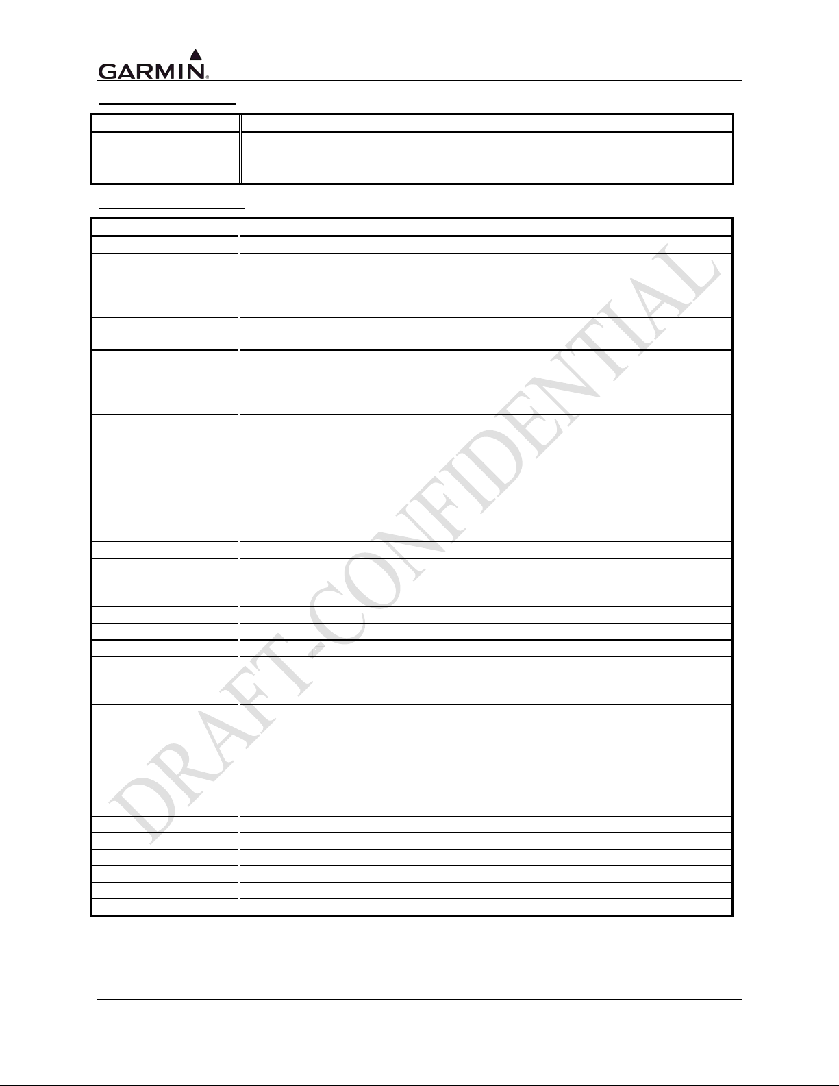
SPEED SELECTIONS
Selection Description
Low
Standard low-speed ARINC 429 (nominally 12.5 Kb per second)
High
DATA IN SELECTIONS
Selection Description
Off
Airdata
Airdata/AHRS
Data Concentrator
EFIS
EFIS/Airdata
Garmin GAD 42
Garmin GDU
GTS 800
GTS 820
GTS 850
Honeywell EFIS
INS/IRU
RADAR Graphics
Sandel EHSI
Skywatch
Skywatch HP
KTA 870
KTA 970
Avidyne TAS
High-speed ARINC 429 (nominally 100 Kb per second)
No unit connected to this ARINC 429 input
Altitude, temperature, and speed information from the following Air Data
systems:
B & D 2600, 2601, 2800, 90004-003
Bendix/King KAD 280/480, Shadin ADC 2000
Heading, altitude, temperature, and speed information from an Air Data/AHRS
system.
Garmin and Garmin w/TIS
This is a Garmin data concentration format. Only high speed ARINC 429
should be used.
Garmin GTX 330
Selected course, heading, and joystick waypoint information from the following
EFIS systems:
Bendix/King EFS 40/50
Certain versions of Collins EFIS may also be compatible with this format.
Selected course, heading, joystick waypoint, altitude, temperature, and speed
information from the following systems:
Collins Pro Line 21
Bendix/King EFS 40/50 (with SW 1201 or later)
Selected course, heading, and true airspeed data from the Garmin GAD 42.
Selected course, heading, altitude, temperature and speed information from
the following systems:
Garmin GDU 620 (G500/G600)
Traffic Information from the GTS 800.
Traffic Information from the GTS 820.
Traffic Information from the GTS 850.
Selected course, heading, and joystick waypoint information from the following
EFIS systems:
Honeywell Primus 1000
Heading information from the following Inertial systems:
Bendix/King KAH 460
Collins AHC 85
Honeywell Laseref
Litef LTR 81
Litton LTN 90-100, LTN 91, LTN 92
Joystick waypoint information from a RADAR graphics unit.
Selected Course and Magnetic Heading from a Sandel EHSI.
Traffic Information from the SkyWatch system.
Traffic Information from the SkyWatch system.
Traffic Information from the KTA 870.
Traffic Information from the KTA 970.
Traffic Information from the Avidyne TAS.
Page 5-4 GTN 725/750 TSO Installation Manual
Rev. A 190-01007-02
Page 81
DATA OUT SELECTIONS
Selection [1] Description
Off
ARINC 429
GAMA 429
Bendix King
GAMA 429
GAMA 429
Graphics
GAMA 429 Grph
w/Int
GAMA 429
Pro Line 21
GAMA 429 Sextant
No unit(s) connected to ARINC 429 output
Standard ARINC 429 output data (non-GAMA).
ARINC 429 data as defined by the GAMA General Aviation Subset, 2nd
Edition. The output data includes navigation, flight plan and GPS vertical
guidance information to the following systems:
Bendix/King EFS 40/50 (GPS vertical guidance provided on EFIS)
ARINC 429 data as defined by the General Aviation Manufacturers’
Association (GAMA) General Aviation Subset, 2nd Edition. The output data
includes navigation and flight plan information to the following systems:
Garmin GAD 42 Interface Adapter
Bendix/King EFS 40/50 (No GPS vertical guidance provided)
Collins EFIS 84
Certain other versions of Collins EFIS may also be compatible with this format.
ARINC 429 data as defined by the GAMA General Aviation Subset, 2nd
Edition including GAMA Graphics Protocol ‘A’. This format outputs intersection
symbols as generic waypoint symbols. The output data includes navigation
and flight plan information (including graphical representation of flight plan
procedures) to the following EFIS systems:
Honeywell Primus 1000
ARINC 429 data as defined by the GAMA General Aviation Subset, 2nd
Edition including GAMA Graphics Protocol ‘A’. The output data includes
navigation and flight plan information (including graphical representation of
flight plan procedures) to the following systems:
Sandel SN3308
Sandel SN3500/4500
ARINC 429 data as defined by the GAMA General Aviation Subset, 2nd
Edition. The output data includes navigation and flight plan information to the
following EFIS systems:
Collins Pro Line 21
ARINC 429 data as defined by the GAMA General Aviation Subset, 2nd
Edition. The output data includes navigation and flight plan information to the
following EFIS systems:
Sextant SMD 45
[1] Garmin GTX 330 will work with any output setting
SDI
Selection Description
Common
LNAV 1
LNAV 2
RX: Accepts all 429 inputs
TX: Generates all 429 outputs with SDI = 0.
Number 1 (Pilot) long-range navigator
RX: Accepts 429 inputs with SDI = 0 or 1.
TX: Generates all 429 outputs with SDI = 1.
Number 2 (Copilot) long-range navigator
RX: Accepts 429 inputs with SDI = 0 or 2.
TX: Generates all 429 outputs with SDI = 2.
GTN 725/750 TSO Installation Manual Page 5-5
190-01007-02 Rev. A
Page 82
5.4.2 Main RS-232 Config Page
Select the Main RS-232 Configuration page from the
Main GTN Setup page by touching the RS-232
button. See Figure 5-3. Change the inputs or outputs
to match the equipment that is installed in the
aircraft. Touch the button corresponding to the
RS-232 channel and select the applicable input or
output setting. The input/output settings are described
below. Touch the UP or DOWN button to scroll
through the RS-232 selections.
CHANNEL INPUT SELECTIONS
Figure 5-4. Main RS-232 Configuration Page
Selection Description
Off
Arnav ei-fuel
GMA 35
GTX 32 # 1
GTX 32 # 2
GTX 33 # 1
GTX 33 # 2
GTX 33 # 1 with TIS
GTX 33 # 2 with TIS
Icarus ALT
Shadin ADC
Shadin ALT
Shadin FADC
Shadin Fuel
WX-500
GPS
No unit(s) connected to input of this channel.
Serial fuel flow information from the following units:
ARNAV FC-10, FT-10
Electronics International FP-5L
Audio panel status information.
Altitude data, flight ID, and GTX 32 status.
Altitude data, flight ID, and GTX 32 status.
GTX 33 status data, ICAO address, and Flight ID.
GTX 33 status data, ICAO address, and Flight ID.
GTX 33 status data, TIS data, ICAO address, and Flight ID.
GTX 33 status data, TIS data, ICAO address, and Flight ID.
Serial altitude data from the following units:
Icarus Instruments 3000
Sandia SAE5-35
Garmin GTX 327 Transponder
Trans-Cal Industries IA-RS232-X, SSD120
ACK Technologies A-30 (Mod 8 and above)
Serial air data information from the following units:
Shadin ADC 200, 200+, 2000
Serial altitude data from the following units:
Shadin 8800T, 9000T, 9200T
Serial air data and fuel flow information from the following units:
Shadin 9628XX-X Fuel/Air Data Computer
INSIGHT TAS 1000 Air Data Computer
Serial fuel flow information from the following units:
Shadin 91053XM Digital Fuel Management System
Shadin 91204XM Digital Fuel Management System
JP Instruments EDM-700 or EDM-760 Engine Monitor
Lightning strike information from an L3 Communications WX-500 Stormscope.
Page 5-6 GTN 725/750 TSO Installation Manual
Rev. A 190-01007-02
Page 83
CHANNEL OUTPUT SELECTIONS
Selection Description
Off
ADS-B
Aviation Output
Aviation (no Altitude)
Honeywell EGPWS
GMA 35
GTX 32 # 1
GTX 32 # 2
GTX 33 # 1 with TIS
GTX 33 # 2 with TIS
MapMX
WX-500
GPS
No unit(s) connected to output of this channel.
Serial communication to Garmin GTX 33/330 ES or 33D/330D ES
Transponders.
Serial position, altitude, velocity, and navigation data to the following units:
Argus 3000, 5000, or 7000 Moving Map
Electronics International FP-5L Fuel Flow Computer (non-TSO’d)
Garmin MX20 (V5.6 or later), GMX 200 [1]
Garmin GPSMAP 195, GPSMAP 295 or GPS III Pilot
Garmin GPSMAP 196, GPSMAP 296, and GPSMAP 396
Garmin GTX 327 Transponder
JP Instruments EDM-700 or EDM-760 Engine Monitor
Shadin 91204XM Digital Fuel Management System
Shadin 91053XM Digital Fuel Management System
Shadin 9628XX-X Fuel/Air Data Computer
Stormscope Series II (with NAVAID) Moving Map
Serial position, velocity, and navigation data to the following units:
Garmin MX20 (V5.5 or earlier)
Horizon DDMP
INSIGHT TAS 1000 Air Data Computer
Serial communication to a Bendix/King (Honeywell) KGP 560 EGPWS.
Control of GMA 35 Audio Panel functions.
Control of GTX 32 transponder functions, pressure altitude data, and
groundspeed data.
Control of GTX 32 transponder functions, pressure altitude data, and
groundspeed data.
Control of GTX 33 transponder functions, pressure altitude data, and
groundspeed data.
Control of GTX 33 transponder functions, pressure altitude data, and
groundspeed data.
Serial position, altitude, velocity, and navigation data to the following units:
Garmin MX20 (V5.7 or later), GMX 200
Serial communication to an L3 Communications WX-500 Stormscope.
GTN 725/750 TSO Installation Manual Page 5-7
190-01007-02 Rev. A
Page 84

5.4.3 HSDB (Ethernet) Configuration Page
The HSDB Ethernet page can be accessed from the GTN
Setup page. Touch the button next to the port to configure it
as ‘Connected’ or ‘Not Connected’. See Figure 5-5. If a
Garmin LRU is connected to a specific Ethernet port, then
configure the port as ‘Connected’. If no LRU is connected
to the port, configure it as ‘Not Connected’.
Figure 5-5. HSDB Ethernet Port Configuration
Page
5.4.4 Interface Equipment Page
Touch the Interface Equipment button on the GTN Setup page.
This page allows the configuration of the presence of a cross-side
navigator, GDL 69/69A, Transponder #1 and Transponder #2.
Figure 5-6. Interfaced Equipment Page
Page 5-8 GTN 725/750 TSO Installation Manual
Rev. A 190-01007-02
Page 85
5.4.5 Main CDI Indicator (Analog) Configuration Page
Touch the Main Indicator (Analog) button on the GTN
Setup page. See Figure 5-3. This page allows you to
calibrate the OBS resolver, enable the CDI key, selected
course for GPS and/or VLOC, and configure the V-Flag
state. The following fields can be configured, as shown in
Figure 5-7.
CALIBRATE OBS RESOLVER
To calibrate the OBS resolver, touch the ‘Calibrate’ button
on the Main CDI Configuration page. See Figure 5-7.
Next, select 150˚ on the OBS, then touch the OK button, as
prompted on the display. After the OBS resolver is
finished calibrating, the GTN will display ‘OBS Resolver
Calibration Complete’. Touch ‘OK’ after the calibration is
complete. Verify OBS operation by checking that the
course displayed on the GTN is within 2° of the selected
course. Do this at 30° intervals around the OBS card.
CDI KEY
If it is desired to disable the CDI key, touch the button to
the right of ‘CDI Key’ to toggle between enabling and
disabling the CDI key. Disabling the CDI key causes the CDI source to always be displayed as GPS
regardless of CDI button presses. This may be necessary for certain EFIS systems where navigation
sensor selection must be accomplished on the EFIS or its control panel.
Figure 5-7. Main Indicator (Analog) Configuration
Page
SELECTED COURSE FOR GPS
If it is desired to ignore a selected course input for GPS operation in OBS mode, touch the button to the
right of ‘Selected Course for GPS’ until ‘Ignored’ is displayed on the button.
SELECTED COURSE FOR VLOC
If it is desired to ignore a selected course input such that the VOR valid flag is dependent only on a valid
VOR signal, with lateral deviation calculated by another display device, touch the button to the right of
‘Selected Course for VLOC’ until ‘Ignored’ is displayed on the button.
V-FLAG STATE
Select either Normal or Declutter for the V-Flag State by touching the button until the desired selection is
displayed on the button.
Selection Description
Whenever vertical deviation is invalid, the vertical deviation bar is
parked in the maximum UP position and the vertical flag is removed
from view, except in the following cases: (i) the CDI is in VLOC mode
Declutter
Normal
and an ILS frequency is tuned, or (ii) the CDI is in GPS mode and a
GPS approach with vertical guidance is active. In these cases,
whenever the vertical deviation is invalid, the vertical deviation bar
parks in the centered position and the vertical flag is shown.
Whenever vertical deviation is invalid the vertical deviation bar parks in
the centered position and the vertical flag is shown.
GTN 725/750 TSO Installation Manual Page 5-9
190-01007-02 Rev. A
Page 86
5.4.6 Lighting Configuration Page
Select the Lighting Page. See Figure 5-3. This page allows
you to set display parameters that affect the display
backlight and key lighting brightness. The Display and Key
lighting characteristics are adjusted separately, each with
the following fields:
SOURCE
Selection Description
Photocell
Lighting Bus 1
Lighting Bus 2
Backlight or key lighting level is determined by the ambient light level
as measured by the photocell on the GTN.
Backlight or key levels track the Lighting Bus 1 levels.
Key lighting levels track the Lighting Bus 2 levels.
Figure 5-8. Main Lighting Configuration Page
Note that the display source can only be configured to track the photocell or lighting bus 1.
MINIMUM LEVEL
This sets the minimum brightness of the keys or display, whichever is applicable. Touch the ‘Minimum
Level’ button corresponding to either the Keys or the Display to adjust the minimum brightness. The
minimum brightness level can be adjusted in a range from 0.05% to 100.00%, with 100.00% being the
highest brightness level. The minimum display and key brightness default level is set to 5.00% at the
factory. Enter the desired minimum value on the keypad and then touch ENTER to store the settings.
Page 5-10 GTN 725/750 TSO Installation Manual
Rev. A 190-01007-02
Page 87

5.4.6.1 Configure Photocell Page
Touching ‘Configure Photocell’ (See Figure 5-8) from
the Lighting Configuration page allows the following
parameters to be configured by touching the
corresponding button. Each selection displays a
numeric keypad where the numeric values can be
entered.
RESPONSE TIME
Sets the speed with which the brightness responds to
the input level (bus voltage or ambient light) changes.
The higher the number the slower the display responds.
This field has a range of 2-7 seconds, and is set to 2
seconds as a default value.
SLOPE
Sets the sensitivity the brightness of the display has to
changes in the input level. The higher the number, the
brighter the display for a given increase in the input
Figure 5-9. Photocell Configuration Page
level. This field has a range of 0-100, and is set to 50 as
the default setting.
OFFSET
Adjusts the lighting level up or down for any given input level. This field has a range of 0 (zero) to 99,
and is set to 50 as a default value. This may also be used to match lighting curves with other equipment
in the panel.
KEY BACKLIGHT CUTOFF
This parameter configures the point at which key backlighting is switched off in bright light. For example,
a value of 70% means that the key backlights will be off at photocell source input levels above 70%. This
field has a range of 0 (zero) to 100% and is set to 80% as the default setting.
PHOTOCELL TRANSITION
When a lighting bus is used to control the lighting of the display, this parameter sets the point on the
lighting bus control below which the display brightness tracks the GTN’s photocell. This field has a
range of 0 (zero) to 50, and is set to 25 as the default setting.
GTN 725/750 TSO Installation Manual Page 5-11
190-01007-02 Rev. A
Page 88

5.4.6.2 Configure Lighting Bus Page
The Lighting Bus Configuration page offers the same
Response Time, Slope, and Offset adjustments as
described in Section 5.4.6.1.
LIGHTING BUS SOURCE
To configure the lighting bus source voltage, touch the
‘Lighting Bus 1’ or ‘Lighting Bus 2’ button. Select 14V
DC, 28V DC, 5V DC, or 5V AC depending on the
lighting bus voltage source.
5.4.7 Audio Configuration Page
Figure 5-10. Lighting Bus Configuration Page
The Audio Configuration page allows the adjustment of volume
alerts. See Figure 5-11. Touch the Audio button on the GTN
Setup page. To adjust the alert volume, press the ‘ – ‘ or the ‘ + ‘
sign to decrease or increase the volume accordingly. The
volume is displayed as a percentage of maximum volume, with
0% being muted and 100% being max volume. The selected
volume level can be checked by selecting ‘Test Sound’ and then
touching the green triangle to the right of the button.
Figure 5-11. Audio Configuration Page
Page 5-12 GTN 725/750 TSO Installation Manual
Rev. A 190-01007-02
Page 89

5.4.8 Traffic Configuration Page
Access the Traffic Configuration Page from the Main GTN
Configuration home page. See Figure 5-3. The Traffic
Configuration page allows the traffic intruder symbol color and
external control to be configured for each specific installation.
To adjust the traffic intruder symbol color, touch the button to
toggle between white or cyan, as shown in Figure 5-12. White
is the default symbol color.
Configure the GTN control of the traffic system. If the GTN is
used to control the traffic system, touch the button and select
‘Yes’. If a separate display device is used to control the traffic
system, select ‘No’.
Figure 5-12. Traffic Configuration Page
5.4.9 Main System Configuration Page
Touch the Main System button from the GTN Setup page. See Figure 5-3. This page displays
miscellaneous configuration options.
AIR/GROUND THRESHOLD
The air/ground threshold is the speed at which the GTN transitions from a ground state to an airborne
state, and vice versa. To adjust the air/ground threshold, touch the button to the left and enter a value.
This field has a range of 0 (zero) to 99 knots and is set to 30 knots as a default value.
AIR/GROUND DISCRETE
The air/ground discrete is the ------. To adjust the air/ground
threshold, touch the button to the left and enter a value. This
field two options: Active for Airborne and Active for
Ground.
GPS ANTENNA HEIGHT ABOVE GROUND
This configures the height of the GPS antenna above ground
level while the aircraft is sitting on the ground. Before
proceeding, measure the GPS antenna vertical offset (to the
nearest tenth of a foot) as shown in Figure 5-13. Enter the
measured value by touching the button and entering the
measured value into the keypad on the display. This field has
a range of 0.0 to 99.9 feet.
FUEL TYPE
This configures the type of fuel the aircraft uses. Options
are AV Gas, Jet A, or Jet B.
GPS SELECT
Figure 5-13. Main System Configuration Page
????
GTN 725/750 TSO Installation Manual Page 5-13
190-01007-02 Rev. A
Page 90
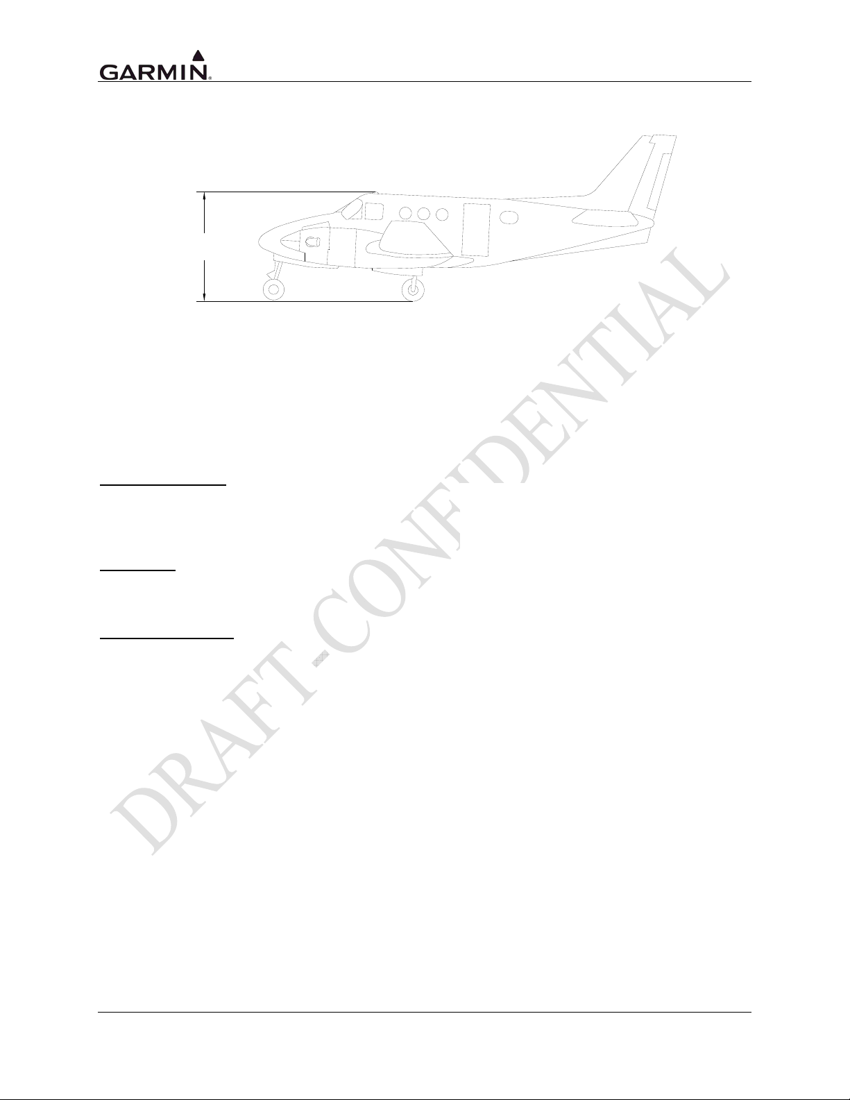
GPS Antenna
Vertical Offset (ft)
Figure 5-14. Measurement of GPS Antenna Vertical Offset
5.4.10 COM Configuration Page (GTN 750 Only)
Select the COM configuration page from the main GTN Setup page as shown in Figure 5-3. These values
are set at the factory and rarely require calibration.
To enable or disable the COM radio, touch the button to toggle between ‘Enabled’ and ‘Disabled’. The
COM radio defaults to enabled state. See Figure 5-15.
COM RF SQUELCH
This setting configures the RF squelch threshold for
the COM radio. This field may be set to any value
between 0% and 100%.
MIC 1 GAIN
This can be adjusted to 12 dB, 18 dB, 24 dB, or 30
dB.
SIDETONE VOLUME
This parameter sets the audio sidetone output level.
This value may be set to values between 0.0 dB and
63.0 dB in 0.5 dB increments. The default is TBD
dB.
Figure 5-15. COM Configuration Page
Page 5-14 GTN 725/750 TSO Installation Manual
Rev. A 190-01007-02
Page 91
5.4.11 VOR/LOC/GS Configuration Page
Select the VOR/LOC/GS from the GTN Setup page
by touching the button on the display. See Figure 5-3.
This page allows you to verify and calibrate the CDI
outputs from the VOR/LOC/GS receiver as well as
the OBS resolver input to the VOR receiver. It also
allows you to select the format for the DME tuning
data.
ENABLE/DISABLE NAV RADIO
Touch the button to disable or enable the NAV Radio.
CALIBRATE OBS RESOLVER
To calibrate the OBS resolver, touch the ‘Calibrate’
button from the VOR/LOC/GS Configuration page.
See Figure 5-16. Next, select 150˚ on the OBS, then
touch the OK button, as prompted on the display.
After the OBS resolver is finished calibrating, the
GTN will display ‘OBS Resolver Calibration
Complete’. Touch ‘OK’ after the calibration is
complete. Verify OBS operation by checking that the
course displayed on the GTN is within 2° of the
selected course. Do this at 30° intervals around the
OBS card.
Figure 5-16. VOR/LOC/GS Configuration Page
ARINC 429 CONFIGURATION SPEED (RX AND TX)
Selection Description
Low
High
SDI
Selection Description
Common
VOR/ILS 1
VOR/ILS 2
DME MODE
Selection Description
Directed freq 1
Directed freq 2
Standard low-speed ARINC 429 (nominally 12.5 kilobits per second)
High-speed ARINC 429 (nominally 100 kilobits per second)
RX: Accepts all 429 inputs
TX: Generates all 429 outputs with SDI = 0.
Number 1 (Pilot) VOR/ILS Receiver
RX: Accepts 429 inputs with SDI = 0 or 1.
TX: Generates all 429 outputs with SDI = 1.
Number 2 (Copilot) VOR/ILS Receiver
RX: Accepts 429 inputs with SDI = 0 or 2.
TX: Generates all 429 outputs with SDI = 2.
If the GTN is connected to a multi-channel ARINC 429 DME, channel
1 of that DME is tuned. “Directed freq 1” should be selected if a
single-channel ARINC 429 DME is to be tuned.
If the GTN is connected to a multi-channel ARINC 429 DME, channel
2 of that DME is tuned.
GTN 725/750 TSO Installation Manual Page 5-15
190-01007-02 Rev. A
Page 92
DME CHANNEL MODE
This configuration setting allows you to set the format for DME tuning data output.
Selection Description
King serial
Parallel 2x5
Parallel BCD
Parallel slip
Narco 890/891
King Serial DME tuning data
2 of 5 parallel DME tuning.
Shifted BCD (Binary Coded Decimal) parallel DME tuning
Slip-code parallel DME tuning
2 of 5 parallel DME tuning, compatible with the following DME units:
Narco DME 890
Narco DME 891
ARC (Cessna) RTA-476A
Page 5-16 GTN 725/750 TSO Installation Manual
Rev. A 190-01007-02
Page 93

5.5 Ground Checks (Configuration Mode)
The following checks are done in Configuration Mode. For instructions concerning entering
Configuration Mode, see Section 5.4.
5.5.1 Main Indicator Check (Analog Only)
NOTE
If the GTN is interfaced to an electronic HSI and the main indicator analog output is not
used, this check is not required.
If the GTN is interfaced to an analog indicator on the main
CDI/OBS, perform the following steps:
1. Go to the GTN Diagnostics page. See Figure 5-17.
2. Go to the Main Indicator (Analog) page.
3. Verify correct operation of the lateral deviation, flag
and TO/FROM flag using the corresponding
selections.
4. Verify correct operation of the vertical deviation
and flag using the corresponding selections.
5. Verify correct operation of the OBS knob using the
SELECTED COURSE display. At 30° increments
around the OBS card, ensure that the indicated
value is within 2° of the value set on the indicator.
If the resolver is not within 2°, calibrate the resolver
as described in Section 5.4.4.
Figure 5-17. GTN Diagnostics Page
5.5.2 VOR/ILS Indicator (Analog)
If the GTN is interfaced to an analog indicator on the VOR/ILS Indicator output, perform the following
steps:
1. Go to the GTN Diagnostics page. See Figure 5-17.
2. Go to the NAV page.
3. Verify correct operation of the lateral deviation, flag and TO/FROM flag using the corresponding
selections.
4. Verify correct operation of the vertical deviation and flag using the corresponding selections.
5.5.3 Discrete Inputs Checkout
If the GTN is connected to external switches, perform the following steps:
1. Go to the GTN Diagnostics page. See Figure 5-17.
2. Go to the Discrete Inputs page.
3. For each external switch that is connected, exercise the switch and check the ‘active’ or ‘inactive’
indication on the screen correlating to the appropriate switch input, and ensure it is displayed
correctly.
GTN 725/750 TSO Installation Manual Page 5-17
190-01007-02 Rev. A
Page 94

5.5.4 Discrete Outputs Checkout
If the GTN is connected to external annunciators/systems, perform the following steps:
1. Go to the GTN Diagnostics page. See Figure 5-17.
2. Go to the Discrete Outputs page.
3. For each annunciator output that is connected to an external system or annunciator, toggle the
output ACTIVE (corresponding box is filled green and displays ‘ACTIVE’) and INACTIVE
(corresponding box is not filled green and displays ‘INACTIVE’) by touching the button
corresponding to the output. Verify that the appropriate external annunciator illuminates when the
output is set to ACTIVE and extinguishes when the output is set to INACTIVE. If the output is
not connected to an annunciator but provides an input to another system, verify that the other
system receives the signal.
5.5.5 HSDB Provisional Wiring Checkout
If provisional wiring has been installed for the
GTS 8XX, GDU 620, or other Garmin LRU to interface via
HSDB, follow the procedure below to ensure it has been
installed correctly.
1. Access the GTN Diagnostics page from the
Configuration Mode home page. See Figure 5-17.
2. Touch the HSDB (Ethernet) button.
3. For each Ethernet port that has provisional wiring
connected to it, ensure that the port status displays
‘Connected’.
Figure 5-18. HSDB Diagnostics Page
Page 5-18 GTN 725/750 TSO Installation Manual
Rev. A 190-01007-02
Page 95

5.5.6 TAWS Audio Check (For Units with TAWS Only)
NOTE
The audio panel should also be turned on for this test.
The TAWS audio volume has an initial default of 80% of the maximum volume value. The TAWS
volume needs to be set so as to ensure that aural alerts are audible under all anticipated noise
environmental conditions.
1. Touch the Audio configuration page from the GTN Setup
page. See Figure 5-19.
2. Next to ‘Alert Audio’, increase or decrease the volume by
touching the ‘+’ or ‘-‘ button.
3. Evaluate the TAWS audio messages for acceptable
volume and intelligibility during both low and high
cockpit noise levels (idle descent at low speed and high
power at Vmo).
4. Readjust the Volume as needed to ensure the TAWS
audio messages will be heard in all anticipated cockpit
noise conditions.
Figure 5-19. GTN Audio
Configuration Page
GTN 725/750 TSO Installation Manual Page 5-19
190-01007-02 Rev. A
Page 96

5.5.7 GAD 42 Interface Check
This check verifies that the GTN is interfaced with the GAD 42.
Go to the GAD 42 Configuration Page from the External
Systems page. Touch ‘External Systems’, then touch ‘GAD 42’.
1. Verify that Status is ACTIVE.
2. Change any of the options to a different number.
3. Verify that after changing one of the options the
STATUS field changes to SENDING then changes back
to ACTIVE. If the entry reverts to the previous number
when ACTIVE is displayed, then refer to the latest
revision of the GAD 42 Installation Manual
(P/N 190-00159-00).
5.5.8 Lighting Bus Interface Check
The display and key backlighting on the GTN can track an
external lighting/dimmer bus input and use it to vary the display
and key backlight levels accordingly. This check verifies that the
interface is connected correctly.
CAUTION
When 14 VDC or 28 VDC lighting buses are connected to the GTN, connection of the
aircraft lighting bus to the incorrect input pins can cause damage to the GTN. Always start
this test with the dimming bus at the lowest setting, and slowly increase the brightness. If it
is noticed that the LIGHTING level displayed on the GTN does not increase as the lighting
is increased in brightness, verify that the wiring is correct before proceeding.
1. Go to the Lighting Bus Configuration page from the
GTN Setup page. See Figure 5-21.
2. Ensure the lighting bus is set to its minimum setting.
3. Slowly vary the lighting bus level that is connected to
the GTN. Verify that the Source Input Level value
displayed on the configuration screen tracks the lighting
bus setting. Continue to maximum brightness and verify
proper operation.
Figure 5-20. GAD 42 Configuration
Page
Figure 5-21. Lighting Bus Configuration Page
Page 5-20 GTN 725/750 TSO Installation Manual
Rev. A 190-01007-02
Page 97

5.6 Ground Checks (Normal Mode)
For the following checks, cycle power on the GTN and power it up in normal mode.
5.6.1 Display of Self-Test Data
Following normal power-up, the Database pages are displayed, followed by the Instrument Panel SelfTest page. Pressing ‘Continue’ displays the Instrument Panel Self-Test page. During this time, the
electrical outputs are activated and set to the values listed below. Touch ‘Continue’ to acknowledge the
self test page. This is not a required check, although this page can be useful for troubleshooting
installation problems.
Parameter Self-Test Value
Course Deviation
Glideslope/Vert. Deviation
Annunciators
Bearing to Waypoint (RMI)
Selected Course (OBS)
Desired Track
Items below are not displayed on the INSTRUMENT PANEL SELF-TEST page
Distance to Go
Time to Go
Active Waypoint
Groundspeed
Present Position
Waypoint Alert
Phase of Flight
Message Alert
Leg/OBS Mode
GPS Integrity
Roll Steering (if applicable)
Half-scale left deviation, TO indication, flag pulled
Half-scale up deviation, flag pulled
All On
135°
The GTN displays the OBS value (149.5° if interfaced to an HSI
with driven course pointer).
149.5° (Displayed as 150°)
10.0 nautical miles
4 minutes
“GARMN”
150 knots
N 39°04.05’, W 94°53.86’
Active
En Route
Active
Leg Mode
Invalid
Flight Director commands 0° bank (level flight) for 5 seconds;
commands increasing right bank at 1°/second for 5 seconds;
commands 5° right bank for 5 seconds; commands decreasing
right bank at 1°/second for 5 seconds, until command is 0° bank
again. This cycle repeats continuously.
GTN 725/750 TSO Installation Manual Page 5-21
190-01007-02 Rev. A
Page 98

5.6.2 Signal Acquisition Check
NOTE
All other avionics should be turned off at the start of this test, with the GTN powered on.
Ensure the GTN is able to acquire sufficient satellites to compute a GPS position. From the Home page,
touch the AUX button and then touch the GPS Status button. Under ‘Status’, ensure that a 3D Fix, or 3D
Diff Fix is obtained. If the unit is unable to acquire satellites, move the aircraft away from obstructions
which might be shading GPS reception. If the situation does not improve, check the GPS antenna
installation.
NOTE
After installation, the initial acquisition of position can take up to 20 minutes.
Subsequent acquisitions will not take that long.
Once GPS position information is available, perform the following steps:
1. On the GPS Status Page, verify that the LAT/LON agree with a known reference position.
2. While monitoring the GPS Status Page, turn on other avionics one at a time and check the GPS
signal reception to make sure it is not affected (no significant signal degradation).
3. Before proceeding with the VHF COM interference check, ensure that any connected equipment
is transmitting and/or receiving data from the GTN and is functioning properly.
5.6.3 VHF COM Interference Check
The interference check must be completed on all IFR installations.
It is known that certain non-aviation radios, including marine transceivers, can interfere
with civil aviation navigation and surveillance equipment including the Garmin GTN.
When installing GTN equipment, it is the responsibility of the installer to ensure that the
GTN modification is compatible with all previous aircraft modifications. Garmin
recommends that whenever a GTN is installed in an aircraft that has been modified with
non-aviation radios, particular care should be exercised to verify that these do not
interfere with proper function of the GTN. Special care should also be taken to ensure
that there is no interference with the GTN if non-aviation radios are installed in an
aircraft after a GTN has been installed. If interference is found, it can be addressed by
relocating antennas, rerouting cables, using filters to attenuate unintentional harmonic
frequency transmissions, or using various other techniques for elimination of the
interference. It may be necessary to remove or replace the interfering radio with a model
that does not interfere with the proper functioning of the GTN.
If you are testing a transmitter from a non-aviation device, each frequency must be
verified by transmitting for at least 30 seconds on each channel.
NOTE
NOTE
Page 5-22 GTN 725/750 TSO Installation Manual
Rev. A 190-01007-02
Page 99

Once the Signal Acquisition Test has been completed successfully, perform the following steps:
1. View the Satellite Status Page and verify that at least 7 satellites have been acquired by the GTN.
2. Verify that the GPS “INTEG” flag is out of view.
3. Select 121.150 MHz on the COM transceiver to be tested.
4. Transmit for a period of 35 seconds.
5. Verify that the GPS “INTEG” flag does not come into view.
6. Repeat steps 4 and 5 for the following frequencies:
25 kHz COM CHANNEL SPACING
121.150 MHz 131.225 MHz
121.175 MHz 131.250 MHz
121.200 MHz 131.275 MHz
121.225 MHz 131.300 MHz
121.250 MHz 131.325 MHz
131.200 MHz 131.350 MHz
NOTE
For VHF radios with 8.33 kHz channel spacing, include the following frequencies in
addition to those listed above.
8.33 kHz COM CHANNEL SPACING
121.185 MHz 130.285 MHz
121.190 MHz 131.290 MHz
7. Repeat steps 3 through 6 for all remaining COM transceivers installed in the aircraft.
8. If aircraft is TCAS-equipped, turn on the TCAS system and verify that GPS position remains
valid (if position is lost, the status on the GPS Status page will change to “ACQUIRING”).
9. If aircraft is SATCOM-equipped, use the SATCOM system and verify that GPS position remains
valid (if position is lost, the status on the GPS Status page will change to “ACQUIRING”).
If the GPS “INTEG” flag comes into view, see TBD for options to improve performance.
GTN 725/750 TSO Installation Manual Page 5-23
190-01007-02 Rev. A
Page 100

5.6.4 VHF NAV Checkout (GTN 750 Only)
Touch the CDI key to select VLOC mode, which is indicated by a green ‘VLOC’ annunciation on the
bottom center of the display. Check the VOR reception with ground equipment, operating VOT or VOR,
and verify audio and Morse code ID functions (if possible). Tune a Localizer frequency and verify the
CDI needle and NAV flag, and VDI needle and GS flag operation.
5.6.5 VHF COM Checkout (GTN 750 Only)
5.6.5.1 Antenna Check
If desired, the antenna VSWR can be checked using an inline wattmeter in the antenna coax using
frequencies near both ends of the band. The VSWR should be < 2:1. A VSWR of 2:1 will cause a drop in
output power of approximately 12%.
5.6.5.2 Receiver/Transmitter Operation
Tune the unit to a local VHF frequency and verify the receiver output produces a clear and
understandable audio output. Verify the transmitter functions properly by contacting another station and
getting a report of reliable communications.
5.6.6 TAWS System Check (For Units with TAWS Only)
While on the ground, turn on the GTN following normal power-up procedures. Also turn on the audio
panel.
NOTE
A 3D GPS position fix is required to conduct this check.
1. Select the TAWS page.
2. Touch the MENU button.
3. Select the Test Terrain? field and press the ENT key.
4. Wait until the TAWS self-test completes (10-15 seconds) to hear the TAWS system status aural
message.
• The aural message “TAWS System Test OK” will be annunciated if the TAWS system is
functioning properly.
• The aural message “TAWS System Failure” will be annunciated if the TAWS system is
NOT functioning properly.
If no audio message is heard, then a fault exists within the audio system and the TAWS capability must
be considered non-functional.
Page 5-24 GTN 725/750 TSO Installation Manual
Rev. A 190-01007-02
 Loading...