

Page 1

GTS 8XX/GPA 65
Installation Manual
(Includes the GA 58 Antenna)
190-00587-00 April, 2009 Revision 4TP
Page 2
© Copyright 2009
Garmin Ltd. or its subsidiaries
All Rights Reserved
Except as expressly provided herein, no part of this manual may be reproduced, copied, transmitted,
disseminated, downloaded or stored in any storage medium, for any purpose without the express prior
written consent of Garmin. Garmin hereby grants permission to download a single copy of this manual
and of any revision to this manual onto a hard drive or other electronic storage medium to be viewed and
to print one copy of this manual or of any revision hereto, provided that such electronic or printed copy of
this manual or revision must contain the complete text of this copyright notice and provided further that
any unauthorized commercial distribution of this manual or any revision hereto is strictly prohibited.
Garmin International, Inc.
1200 E. 151
st
Street
Olathe, KS 66062 USA
Telephone: 913-397-8200
Aviation Dealer Technical Support Line (Toll Free): (888) 606-5482
www.garmin.com
Garmin (Europe) Ltd
Liberty House
Bulls Copse Road
Hounsdown Business Park
Southampton, SO40 9RB, UK
Telephone: +44 (0) 8708501241
RECORD OF REVISIONS
Revision
1TP 08/06/08 1TP Release
2TP 9/17/08 Updated manual with various engineering changes
3TP 2/18/09 Updated manual with various engineering changes
4TP Updated manual with various engineering changes
Revision
Date
Description
DOCUMENT PAGINATION
Section Page Range
Table of Contents i – vi
Section 1 1-1 – 1-10
Section 2 2-1 – 2-16
Section 3 3-1 – 3-20
Section 4 4-1 – 4-14
Appendix A A-1 – A-14
Appendix B B-1 – B-18
Page A GTS 8XX/GPA 65 Installation Manual
Revision 4TP 190-00587-00
Page 3

This manual reflects the operation of software version X.XX. Some differences in operation may be
observed when comparing the information in this manual to earlier or later software versions.
INFORMATION SUBJECT TO EXPORT CONTROL LAWS
This document may contain information which is subject to the Export Administration Regulations
(“EAR”) issued by the United States Department of Commerce (15 CFR, Chapter VII Subchapter C) and
which may not be exported, released or disclosed to foreign nationals inside or outside the United States
without first obtaining an export license. The preceding statement is required to be included on any and
all reproductions in whole or in part of this manual.
NOTE
Throughout this document references made to the GTS 8XX shall equally apply to the
GTS 800, 820, and 850 except where specifically noted.
WARNING
This product, its packaging, and its components contain chemicals known to the State of
California to cause cancer, birth defects, or reproductive harm. This Notice is being
provided in accordance with California's Proposition 65. If you have any questions or
would like additional information, please refer to our web site at
www.garmin.com/prop65
.
GTS 8XX/GPA 65 Installation Manual Page i
190-00587-00 Revision 4TP
Page 4

This page intentionally left blank
Page ii GTS 8XX/GPA 65 Installation Manual
Revision 4TP 190-00587-00
Page 5

TABLE OF CONTENTS
PARAGRAPH PAGE
1 GENERAL DESCRIPTION..............................................................................................................1-1
1.1 Introduction........................................................................................................................................1-1
1.2 Equipment Description......................................................................................................................1-1
1.3 Interface Summary.............................................................................................................................1-1
1.4 Technical Specifications....................................................................................................................1-2
1.5 Certification.......................................................................................................................................1-4
1.6 Reference Documents........................................................................................................................1-8
1.7 Limited Warranty...............................................................................................................................1-9
2 INSTALLATION OVERVIEW........................................................................................................2-1
2.1 Introduction........................................................................................................................................2-1
2.2 Installation Considerations ................................................................................................................2-3
2.3 Electrical Bonding .............................................................................................................................2-5
2.4 Cabling and Wiring............................................................................................................................2-5
2.5 Cooling Requirements .....................................................................................................................2-15
2.6 Mounting Requirements ..................................................................................................................2-16
3 INSTALLATION PROCEDURE......................................................................................................3-1
3.1 Unpacking Unit..................................................................................................................................3-1
3.2 Wiring Harness Installation...............................................................................................................3-1
3.3 QMA Connector Insertion and Removal...........................................................................................3-3
3.4 Backshell, Pigtail Circular Connector, and Configuration Module Assemblies................................3-5
3.5 Unit Installation .................................................................................................................................3-5
3.6 GA 58 Antenna Installation.............................................................................................................3-19
3.7 GPA 65 PA/LNA Installation..........................................................................................................3-20
3.8 Continued Airworthiness.................................................................................................................3-20
4 SYSTEM INTERCONNECTS..........................................................................................................4-1
4.1 GTS 8XX Pin Function List ..............................................................................................................4-1
4.2 GPA 65 Pin Function List..................................................................................................................4-6
4.3 Power.................................................................................................................................................4-7
4.4 Serial Data .........................................................................................................................................4-9
4.5 Configuration...................................................................................................................................4-12
4.6 Analog/Discrete...............................................................................................................................4-12
4.7 Mutual Suppression Bus..................................................................................................................4-14
APPENDIX A: OUTLINE & INSTALLATION DRAWINGS..............................................................A-1
APPENDIX B: INTERCONNECT EXAMPLE...................................................................................... B-1
GTS 8XX/GPA 65 Installation Manual Page iii
190-00587-00 Revision 4TP
Page 6

LIST OF ILLUSTRATIONS
FIGURE PAGE
2-1 GTS 800 Installation with Top and Bottom Directional Antennas....................................................2-7
2-2 GTS 800 Installation with Top and Bottom Monopole Antennas.....................................................2-8
2-3 GTS 800 Installation with Top Directional Antennas and no Bottom Antenna................................2-8
2-4 GTS 820/GTS 850 Installation Top and Bottom Directional Antennas............................................2-9
2-5 GTS 820/GTS 850 Installation with Top Directional and Bottom Monopole Antenna..................2-10
2-6 GTS 820/GTS 850 Installation with Top Directional and no Bottom Antenna...............................2-10
2-7 RG-400/RG-142 Coaxial Cable Stripping Dimensions...................................................................2-14
2-8 Ferrule and Crimp Die Positioning..................................................................................................2-14
2-9 Heat Shrink Positioning...................................................................................................................2-15
2-10 GTS 8XX Vertical Installation Rack (Garmin P/N 115-00781-00) ................................................2-16
2-11 GTS 8XX Horizontal Installation Rack (Garmin P/N 115-00784-00)............................................2-16
3-1 Engaging QMA Connectors...............................................................................................................3-3
3-2 Disengaging QMA Connectors..........................................................................................................3-4
3-3 GTS 8XX Install Tool – Normal Tab................................................................................................3-7
3-4 GTS 8XX Install Tool – Configuration Tab (GTS 800)....................................................................3-8
3-5 GTS 8XX Install Tool – Configuration Tab (GTS 820 and GTS 850)..............................................3-9
3-6 GTS 8XX Install Tool – Upload Tab...............................................................................................3-12
3-7 Self Test...........................................................................................................................................3-15
3-8 Ground Test .....................................................................................................................................3-16
A-1 GTS 8XX Vertical Outline Drawing ................................................................................................A-1
A-2 GTS 8XX Vertical Installation Drawing ..........................................................................................A-3
A-3 GTS 8XX Horizontal Outline Drawing............................................................................................A-5
A-4 GTS 8XX Horizontal Installation Drawing......................................................................................A-7
A-5 GPA 65 Outline Drawing .................................................................................................................A-9
A-6 GPA 65 Installation Drawing .........................................................................................................A-11
A-7 GA 58 Antenna Outline Drawing...................................................................................................A-13
B-1 Notes................................................................................................................................................. B-1
B-2 GTS 820/850/GPA 65 Example Interconnect ................................................................................... B-3
B-3 GTS 800 Example Interconnect........................................................................................................ B-5
B-4 GTS 8XX G1000 Example Interconnect ..........................................................................................B-7
B-5 GTS 8XX GNS 4XX/GNS 5XX/GMX 200 Example Interconnect.................................................B-9
B-6 GTS 8XX/GMA/Altimeter Example Interconnect ......................................................................... B-11
B-7 GTS 8XX Dongle Cable (Non-G 1000 Installations Only).............................................................B-13
B-8 GTS 8XX Discrete Interconnects ................................................................................................... B-15
B-9 GTS 8XX Config Module Example Interconnect .......................................................................... B-17
Page iv GTS 8XX/GPA 65 Installation Manual
Revision 4TP 190-00587-00
Page 7

LIST OF TABLES
TABLE PAGE
2-1 GPA 65 Minimum Wiring Requirements..........................................................................................2-6
2-2 Cable Types and QMA Connectors.................................................................................................2-11
2-3 Recommended Coaxial Length........................................................................................................2-12
2-4 Coaxial Cable Set Length Tolerance ...............................................................................................2-13
3-1 Socket and Pin Contact part Numbers...............................................................................................3-1
3-2 Socket Contact MIL SPEC M39029/5-115 Crimp Tooling...............................................................3-1
3-3 Pin Contact GPN 336-00021-00 MIL SPEC M39029/58-360 Crimp Tooling .................................3-2
3-4 Pin Socket Contacts GPN 336-00022-00 MIL SPEC M39029/63-368 and GPN 336-00023-00 Crimp
Tooling...............................................................................................................................................3-2
3-5 Self Test...........................................................................................................................................3-15
GTS 8XX/GPA 65 Installation Manual Page v
190-00587-00 Revision 4TP
Page 8
GTS 8XX HARDWARE MOD LEVEL HISTORY
The following table identifies hardware modification (Mod) Levels for the GTS 8XX. Mod Levels are
listed with the associated service bulletin number, service bulletin date, and the purpose of the
modification. The table is current at the time of publication of this manual (see date on front cover) and is
subject to change without notice. Authorized Garmin Sales and Service Centers are encouraged to access
the most up-to-date bulletin and advisory information on the Garmin Dealer Resource web site at
www.garmin.com
APPLICABLE
LRU PART
NUMBER
using their Garmin-provided user name and password.
MOD
LEVEL
SERVICE
BULLETIN
NUMBER
SERVICE
BULLETIN
DATE
PURPOSE OF
MODIFICATION
Page vi GTS 8XX/GPA 65 Installation Manual
Revision 4TP 190-00587-00
Page 9
(
)
1 GENERAL DESCRIPTION
1.1 Introduction
This manual presents mechanical and electrical installation requirements for installing the
GTS 8XX/GPA 65 Traffic Advisory System (TAS) and Traffic Collision Avoidance System (TCAS I).
1.2 Equipment Description
The GTS 8XX is a microprocessor-based Line Replaceable Unit (LRU) that uses active interrogations of
Mode S (GTS 820 and GTS 850 only) and Mode C transponders to provide Traffic Advisories to the
pilot. The GTS 820 and GTS 850 include a GPA 65 power amplifier/low-noise amplifier (PA/LNA)
module, which allows for up to 40 nm of active surveillance range as well as Mode S interrogation
capability. When installed with a 1090 MHz ADS-B transmit class of equipment the GTS 8XX also
utilizes passive surveillance. Traffic is displayed on an external MFD via ARINC 429 and/or Ethernet
High Speed Data Bus (HSDB). An aural alert is also provided to inform the crew a traffic advisory (TA)
will be displayed.
A top-mounted directional antenna is used to derive bearing of the intruder aircraft, which is displayed
with relative altitude to own aircraft. Top antenna transmitted interrogations are directional, reducing the
number of transponders that receive the interrogation thus reducing potential garble on the 1090 MHz
band. Optional bottom antenna transmit interrogations are omni directional, using a monopole antenna
(recommended for fixed gear installations) or a directional antenna (recommended for retractable gear
installations). A bottom directional antenna installation gives the benefit of intruder bearing visibility for
targets that are shaded from the top directional antenna.
1.2.1 GTS 8XX Model Differences
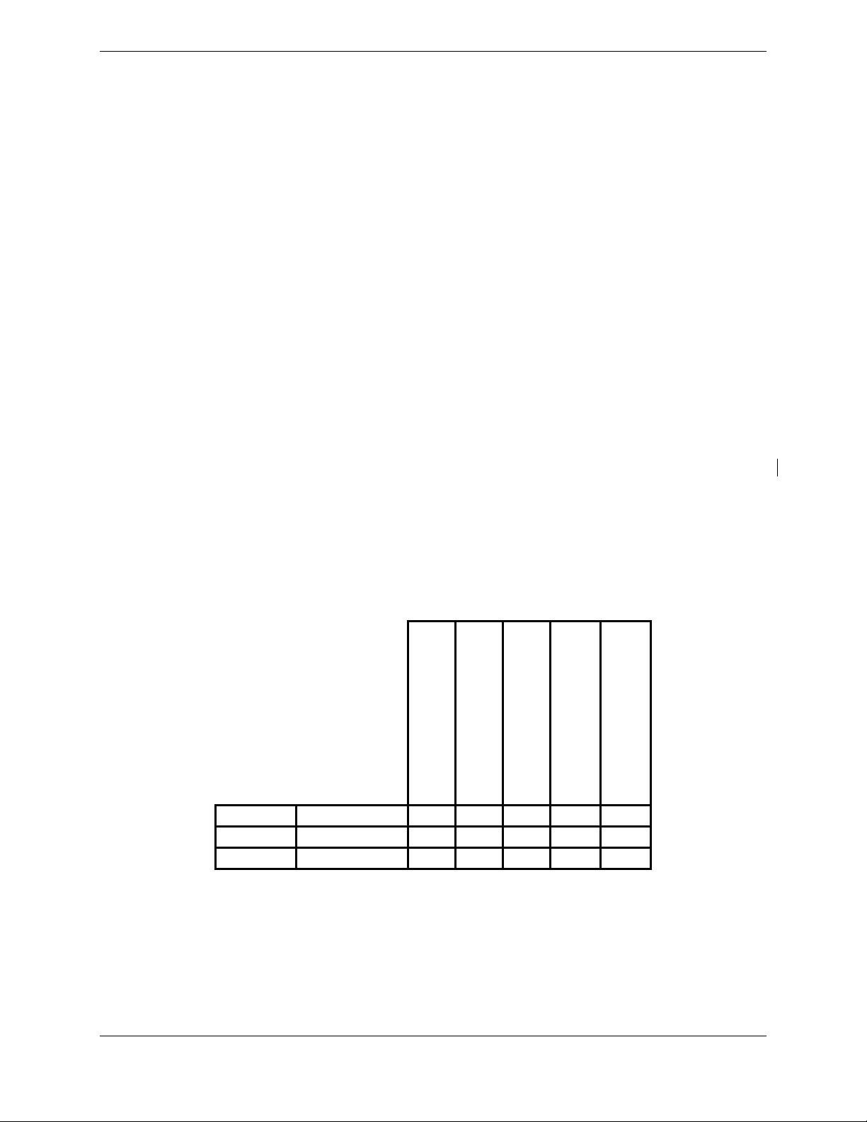
The following table summarizes the differences between the various GTS 8XX models documented in
this manual.
GTS 800 011-01356-00
GTS 820 011-01446-00
GTS 850 011-01553-00
(TAS)
Traffic Advisory System
X X 40
X X X 200
X X X 200
TCAS I
Receiver
Traffic Collision
1090 ES ADS-B
Avoidance System
GPA 65
PA/LNA
(Watts)
Transmit Power
1.3 Interface Summary
The GTS 8XX is designed as an open architecture system that uses typical ARINC 429, RS-232, and
Ethernet communications interfaces.
GTS 8XX/GPA 65 Installation Manual Page 1-1
190-00587-00 Revision 4TP
Page 10

1.4 Technical Specifications
1.4.1 Environmental Qualification Form
It is the responsibility of the installing agency to obtain the latest revision of the GTS 8XX/GPA
Environmental Qualification Form. This form is available directly from Garmin under the following part
number:
GTS 8XX Environmental Qualification Form, Garmin part number 005-00323-02
GPA 65 PA/LNA Environmental Qualification Form, Garmin part number 005-00323-22
GA 58 Antenna Environmental Qualification Form, Garmin part number 005-00232-23
To obtain a copy of this form, see the dealer/OEM portion of the Garmin web site (www.garmin.com
).
1.4.2 Physical Characteristics
Characteristics Specifications
GTS 8XX Width 2.81 inches (7.14 cm)
GTS 8XX Height 6.94 inches (17.63 cm)
GTS 8XX Depth w/Connector Kit 14.78 inches (37.54 cm)
GPA 65 Width 4.25 inches (10.80 cm)
GPA 65 Height 1.00 inches (2.54 cm)
GPA 65 Depth Not Including
Connector And Cable
GPA 65 Depth w/Connector And
Cable Fully Extended
GTS 8XX Unit Weight w/out
Connector Kit
GTS 8XX Unit Weight with
Connector Kit/w Vertical Rack
GTS 8XX Unit Weight with
Connector Kit/w Horizontal Rack
GPA 65 PA/LNA Unit Weight with
Pigtail Connector Kit*
GA 58 TAS/TCAS Antenna
w/screws and o-ring
QMA straight connector kit, 4 pcs 0.10 lbs. (0.05 kg)
QMA straight connector kit, 1 pc 0.03 lbs. (0.01 kg)
QMA right angle connector kit,
4 pcs
QMA right angle connector kit, 1 pc 0.05 lbs. (0.02 kg)
QMA termination connector kit 0.07 lbs. (0.03 kg)
*Used with the GTS 820 and 850.
7.96 inches (20.22 cm)
16.83 inches (42.75 cm)
9.0 lbs. (4.08 kg)
10.7 lbs. (4.85 kg)
11.5 lbs. (5.22 kg)
1.9 lbs. (0.86 kg)
0.82 lbs. (0.37 kg)
0.18 lbs. (0.08 kg)
Page 1-2 GTS 8XX/GPA 65 Installation Manual
Revision 4TP 190-00587-00
Page 11
1.4.3 General Specifications
The table below contains general specifications. For detailed environmental specifications, see the
Environmental Qualification Form.
Characteristics Specifications
Operating Temperature Range -55°C to +70°C.
Humidity 95% non-condensing
Altitude Range -1,500 ft to 55,000 ft
Software Compliance RTCA/DO-178B levels B, C, and D
Hardware Compliance RTCA/DO-254 Level C
Environmental Compliance RTCA/DO-160E
1.4.4 Power Requirements
Characteristics Specifications
GTS 8XX Power Requirements 14/28 Vdc. See the Environmental Qualification Form for
details on surge ratings and minimum/maximum operating
voltages.
GTS 800 Power Consumption 1.1 +/- 0.2 A typical 1.5 A max operating @ 28 Vdc
2.2 +/- 0.2 A typical 2.6 A max operating @ 14 Vdc
GTS 820/850 Power Consumption 1.3 +/- 0.2 A typical 1.6 A max operating @ 28 Vdc
2.7 +/- 0.3 A typical 3.2 A max operating @ 14 Vdc
GTS 8XX Boot-up Current Draw 4.0 A @ 28 Vdc for 70 ms
5.6 A @ 14 Vdc for 100 ms
GTS 8XX/GPA 65 Installation Manual Page 1-3
190-00587-00 Revision 4TP
Page 12

1.5 Certification
The conditions and tests required for TSO approval of this article are minimum performance standards. It
is the responsibility of those installing this article either on or within a specific type or class of aircraft to
determine that the aircraft installation conditions are within the TSO standards. TSO articles must have
separate approval for installation in an aircraft. The article may be installed only if performed under 14
CFR part 43 or the applicable airworthiness requirements.
The following table provides a list of applicable TSO/ETSOs for the GTS 8XX/GPA 65.
1.5.1 TSO/ETSO Compliance
Applicable
LRU
GTS 850
GPA 65
GTS 800
GTS 820
GPA 65
GTS 800
GTS 820
GTS 850
Function TSO/ETSO Category
Traffic Alert and Collision
Avoidance System (TCAS I)
Airborne Equipment
Traffic Advisory System
(TAS) Airborne Equipment
Extended Squitter Automatic
Dependent Surveillance –
Broadcast (ADS-B) and
Traffic Information Service –
Broadcast (TIS-B)
Equipment Operating on the
Radio Frequency of 1090
Megahertz (MHz)
TSO-C118
ETSO-C118
TSO-C147
ETSO-C147
TSO-C166a
Applicable
LRU SW Part
Numbers
006-B0551-()
Class A 006-B0551-()
Class
A0/Type 1
Receiving
Only*
Class
A1/Type 1
Receiving
Only*
006-B0551-() 006-C0081-()**
Applicable
CLD Part
Numbers
006-C0081-()**
006-C0092-()***
006-C0081-()**
006-C0092-()***
* Equipment is Class A0 when installed with a single antenna, Class A1 when installed with diversity
antennas.
**GTS 8XX only
***GPA 65 only
Page 1-4 GTS 8XX/GPA 65 Installation Manual
Revision 4TP 190-00587-00
Page 13

1.5.2 TSO/ETSO Deviations
1.5.2.1 GTS 800
TSO/ETSO Deviation
TSO-C147 1. Garmin was granted a deviation from TSO-C147 section 1.c to use RTCA DO-160E, instead of
RTCA DO-160D as the standard for Environmental Conditions and Test Procedures for Airborne
Equipment.
RTCA DO-197A
RTCA DO-185A
RTCA DO-260A
1. Garmin was granted a deviation from RTCA DO-197A section 2.2.3.2.1 to use the Interrogations
Spectrum requirement of RTCA DO-185A section 2.2.3.3 instead of the requirement of RTCA DO197A section 2.2.3.2.1
3. Garmin was granted a deviation from RTCA DO-197A section 2.2.9.1 to realize the bearing
estimation function using a direction finding antenna augmented by tracked correlated ADS-B data
when such data is available and of sufficient integrity.
4. Garmin was granted a deviation from RTCA DO-197A section 2.2.11 to use the suppression
pulse on the aircraft suppression bus specified by RTCA DO-185A section 2.2.3.12 (70 +/-1 µs from
top antenna and 90 +/-1 µs from bottom antenna) instead of 100 +/-5 µs.
1. Garmin was granted a deviation to use DO-185A as modified by Appendix 1 of TSO-C119B and
‘RWG Recommended Modification 2.0 to TSO-C119B.’
2. Garmin was granted a deviation from RTCA DO-185A section 2.2.3.8.2 Mode S signal definition.
3. Garmin was granted a deviation from RTCA DO-185A section 2.2.4.4.2.2.b to use the Enhanced
Preamble Detection method of RTCA DO-260A Appendix I section I.4.1.
4. Garmin was granted a deviation from RTCA DO-185A section 2.2.4.4.2.2.c to use the Baseline
Multi-sample bit and confidence declaration technique of RTCA DO-260A Appendix I section
I.4.2.3.1.
5. Garmin was granted a deviation from RTCA DO-185A section 2.4.2.1.1.4.
1. Garmin was granted a deviation from RTCA DO-260A section 2.2.4.3.4.7.3.b to use the
Conservative and Brute Force error correction techniques specified by RTCA DO-260A section
2.2.4.4.3.1 instead of section 2.2.4.4.2.2.d and Appendix A, Section 3 of RTCA DO-185A.
2. Garmin was granted a deviation from RTCA DO-260A section 2.2.4.4.2 to use the Conservative
and Brute Force error correction techniques specified by RTCA DO-260A section 2.2.4.4.3.1
instead of section 2.2.4.4.2.2.d and Appendix A, Section 3 of RTCA DO-185A.
3. Garmin was granted a deviation from RTCA DO-260A section 2.2.4.5.b to use the Conservative
and Brute Force error correction techniques specified by RTCA DO-260A section 2.2.4.4.3.1
instead of section 2.2.4.4.2.2.d and Appendix A, Section 3 of RTCA DO-185A.
GTS 8XX/GPA 65 Installation Manual Page 1-5
190-00587-00 Revision 4TP
Page 14

1.5.2.2 GTS 820
TSO/ETSO Deviation
TSO-C147
RTCA DO-197A
RTCA DO-185A
RTCA DO-260A
1. Garmin was granted a deviation from TSO-C147 section 1.c to use RTCA DO-160E, instead of
RTCA DO-160D as the standard for Environmental Conditions and Test Procedures for Airborne
Equipment.
2. Garmin was granted a deviation from TSO-C147 Appendix 1 section 1.6 to use selective Mode S
interrogations as specified by RTCA DO-185A section 2.2.3.8.1 and 2.2.3.9 following all the
applicable protocols for Mode-S surveillance interrogations in the NAS as stated in DO-1 85A and
DO-181C.
1. Garmin was granted a deviation from RTCA DO-197A section 2.2.3.2.1 to use the Interrogations
Spectrum requirement of RTCA DO-185A section 2.2.3.3 instead of the requirement of RTCA DO197A section 2.2.3.2.1
2. Garmin was granted a deviation from RTCA DO-197A section 2.2.3.5 to use the “Mode C Only
All-Call” format specified by RTCA DO-185A section 2.2.3.8.1 instead of the “Mode C” format for
ATCRBS interrogations.
3. Garmin was granted a deviation from RTCA DO-197A section 2.2.9.1 to realize the bearing
estimation function using a direction finding antenna augmented by tracked correlated ADS-B data
when such data is available and of sufficient integrity.
4. Garmin was granted a deviation from RTCA DO-197A section 2.2.11 to use the suppression
pulse on the aircraft suppression bus specified by RTCA DO-185A section 2.2.3.12 (70 +/-1 µs from
top antenna and 90 +/-1 µs from bottom antenna) instead of 100 +/-5 µs.
1. Garmin was granted a deviation to use DO-185A as modified by Appendix 1 of TSO-C119B and
‘RWG Recommended Modification 2.0 to TSO-C119B.’
2. Garmin was granted a deviation from RTCA DO-185A section 2.2.3.8.2 Mode S signal definition.
3. Garmin was granted a deviation from RTCA DO-185A section 2.2.4.4.2.2.b to use the Enhanced
Preamble Detection method of RTCA DO-260A Appendix I section I.4.1.
4. Garmin was granted a deviation from RTCA DO-185A section 2.2.4.4.2.2.c to use the Baseline
Multi-sample bit and confidence declaration technique of RTCA DO-260A Appendix I section
I.4.2.3.1.
5. Garmin was granted a deviation from RTCA DO-185A section 2.4.2.1.1.4.
1. Garmin was granted a deviation from RTCA DO-260A section 2.2.4.3.4.7.3.b to use the
Conservative and Brute Force error correction techniques specified by RTCA DO-260A section
2.2.4.4.3.1 instead of section 2.2.4.4.2.2.d and Appendix A, Section 3 of RTCA DO-185A.
2. Garmin was granted a deviation from RTCA DO-260A section 2.2.4.4.2 to use the Conservative
and Brute Force error correction techniques specified by RTCA DO-260A section 2.2.4.4.3.1
instead of section 2.2.4.4.2.2.d and Appendix A, Section 3 of RTCA DO-185A.
3. Garmin was granted a deviation from RTCA DO-260A section 2.2.4.5.b to use the Conservative
and Brute Force error correction techniques specified by RTCA DO-260A section 2.2.4.4.3.1
instead of section 2.2.4.4.2.2.d and Appendix A, Section 3 of RTCA DO-185A.
Page 1-6 GTS 8XX/GPA 65 Installation Manual
Revision 4TP 190-00587-00
Page 15

1.5.2.3 GTS 850
TSO/ETSO Deviation
TSO-C118
RTCA DO-197A
RTCA DO-185A
RTCA DO-260A
1. Garmin was granted a deviation from TSO-C118 section a.(2) to use RTCA DO-160E, instead of
RTCA DO-160B as the standard for Environmental Conditions and Test Procedures for Airborne
Equipment.
1. Garmin was granted a deviation from RTCA DO-197A section 2.2.3.2.1 to use the Interrogations
Spectrum requirement of RTCA DO-185A section 2.2.3.3 instead of the requirement of RTCA DO197A section 2.2.3.2.1.
2. Garmin was granted a deviation from RTCA DO-197A section 2.2.3.5 to use the “Mode C Only
All-Call” format specified by RTCA DO-185A section 2.2.3.8.1 instead of the “Mode C” format for
ATCRBS interrogations.
3. Garmin was granted a deviation from RTCA DO-197A section 2.2.6 to use selective Mode S
interrogations following all the applicable protocols for Mode-S surveillance interrogations in the
NAS as stated in DO-185A and DO-181C.
4. Garmin was granted a deviation from RTCA DO-197A section 2.2.9.1 to realize the bearing
estimation function using a direction finding antenna augmented by tracked correlated ADS-B data
when such data is available and of sufficient integrity.
5. Garmin was granted a deviation from RTCA DO-197A section 2.2.11 to use the suppression
pulse on the aircraft suppression bus specified by RTCA DO-185A section 2.2.3.12 (70 +/-1 µs from
top antenna and 90 +/-1 µs from bottom antenna) instead of 100 +/-5 µs.
1. Garmin was granted a deviation to use RTCA DO-185A as modified by Appendix 1 of TSOC119B and ‘RWG Recommended Modification 2.0 to TSO-C119B’.
2. Garmin was granted a deviation from RTCA DO-185A section 2.2.3.8.2 Mode S signal definition.
3. Garmin was granted a deviation from RTCA DO-185A section 2.2.4.4.2.2.b to use the Enhanced
Preamble Detection method of RTCA DO-260A Appendix I section I.4.1.
4. Garmin was granted a deviation from RTCA DO-185A section 2.2.4.4.2.2.c to use the Baseline
Multi-sample bit and confidence declaration technique of RTCA DO-260A Appendix I section
I.4.2.3.1.
1. Garmin was granted a deviation from RTCA DO-260A section 2.2.4.3.4.7.3.b to use the
Conservative and Brute Force error correction techniques specified by RTCA DO-260A section
2.2.4.4.3.1 instead of section 2.2.4.4.2.2.d and Appendix A, Section 3 of RTCA DO-185A.
2. Garmin was granted a deviation from RTCA DO-260A section 2.2.4.4.2 to use the Conservative
and Brute Force error correction techniques specified by RTCA DO-260A section 2.2.4.4.3.1
instead of section 2.2.4.4.2.2.d and Appendix A, Section 3 of RTCA DO-185A.
3. Garmin was granted a deviation from RTCA DO-260A section 2.2.4.5.b to use the Conservative
and Brute Force error correction techniques specified by RTCA DO-260A section 2.2.4.4.3.1
instead of section 2.2.4.4.2.2.d and Appendix A, Section 3 of RTCA DO-185A.
GTS 8XX/GPA 65 Installation Manual Page 1-7
190-00587-00 Revision 4TP
Page 16

1.6 Reference Documents
The following publications are sources of additional information for installing the GTS 8XX. Before
installing the GTS 8XX, the technician should read all referenced materials along with the manual.
Part Number Document
190-00313-11 Jackscrew Backshell Installation Instructions
190-00303-00 G1000 System Installation Manual
190-00303-04
190-00903-00 G1000 System Maintenace Manual LJ/VLJ
190-00907-00
G1000 Line Maintenance and Configuration
Manual
G1000 System Maintenance Manual Standard
Piston/Turboprop Aircraft
Page 1-8 GTS 8XX/GPA 65 Installation Manual
Revision 4TP 190-00587-00
Page 17

1.7 Limited Warranty
This Garmin product is warranted to be free from defects in materials or workmanship for two years from
the date of purchase. Within this period, Garmin will at its sole option, repair or replace any components
that fail in normal use. Such repairs or replacement will be made at no charge to the customer for parts or
labor, provided that the customer shall be responsible for any transportation cost. This warranty does not
cover failures due to abuse, misuse, accident or unauthorized alteration or repairs.
THE WARRANTIES AND REMEDIES CONTAINED HEREIN ARE EXCLUSIVE AND IN LIEU OF
ALL OTHER WARRANTIES EXPRESS OR IMPLIED OR STATUTORY, INCLUDING ANY
LIABILITY ARISING UNDER ANY WARRANTY OF MERCHANTABILITY OR FITNESS FOR A
PARTICULAR PURPOSE, STATUTORY OR OTHERWISE. THIS WARRANTY GIVES YOU
SPECIFIC LEGAL RIGHTS, WHICH MAY VARY FROM STATE TO STATE.
IN NO EVENT SHALL GARMIN BE LIABLE FOR ANY INCIDENTAL, SPECIAL, INDIRECT OR
CONSEQUENTIAL DAMAGES, WHETHER RESULTING FROM THE USE, MISUSE, OR
INABILITY TO USE THIS PRODUCT OR FROM DEFECTS IN THE PRODUCT. Some states do not
allow the exclusion of incidental or consequential damages, so the above limitations may not apply to
you.
Garmin retains the exclusive right to repair or replace the unit or software or offer a full refund of the
purchase price at its sole discretion. SUCH REMEDY SHALL BE YOUR SOLE AND EXCLUSIVE
REMEDY FOR ANY BREACH OF WARRANTY.
To obtain warranty service, contact your local Garmin Authorized Service Center. For assistance in
locating a Service Center near you, call Garmin Customer Service at one of the numbers shown below.
Products sold through online auctions are not eligible for rebates or other special offers from Garmin.
Online auction confirmations are not accepted for warranty verification. To obtain warranty service, an
original or copy of the sales receipt from the original retailer is required. Garmin will not replace missing
components from any package purchased through an online auction.
Garmin International, Inc. Garmin (Europe) Ltd.
1200 E. 151st Street Liberty House
Olathe, KS 66062, U.S.A. Bulls Copse Road
Phone: 800/800.1020 Hounsdown Business Park
FAX: 913/397.0836 Southampton, SO40 9RB, UK
Telephone: 44 (0) 8708501241
GTS 8XX/GPA 65 Installation Manual Page 1-9
190-00587-00 Revision 4TP
Page 18

This page intentionally left blank
Page 1-10 GTS 8XX/GPA 65 Installation Manual
Revision 4TP 190-00587-00
Page 19
2 INSTALLATION OVERVIEW
2.1 Introduction
This section provides hardware equipment information for installing the GTS 8XX/GPA 65 and related
hardware. Installation of the GTS 8XX/GPA 65 should follow the aircraft TC or STC requirements.
Cabling is fabricated by the installing agency to fit each particular aircraft. The guidance of FAA
advisory circulars AC 43.13-1B and AC 43.13-2A, where applicable, may be found useful for making
retro-fit installations that comply with FAA regulations.
2.1.1 Unit Configurations
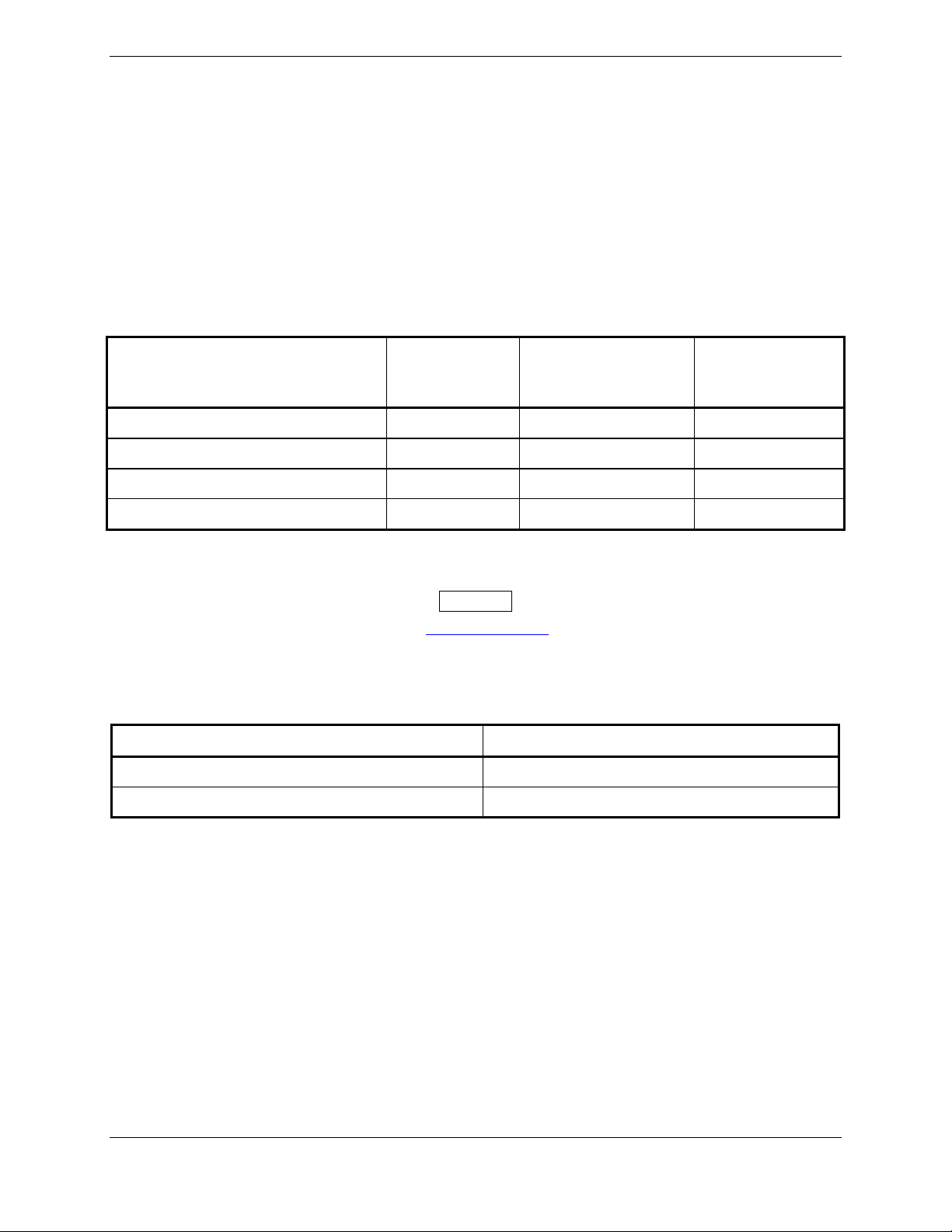
The GTS 8XX and GPA 65 are available under the following part numbers:
Applicable
Item
GTS 800, (011-01356-00) 006-B0551-() 006-C0081-() 010-00519-00
GTS 820, (011-01446-00) 006-B0551-() 006-C0081-() 010-00562-00
GTS 850, (011-01553-00) 006-B0551-() 006-C0081-() 010-00563-00
GPA 65, (011-01347-00) 006-B0551-() 006-C0092-() 010-10721-00
LRU Software
Part Numbers
Applicable Custom
Logic Device
Part Numbers
Garmin P/N
2.1.2 Required Accessories
NOTE
Refer to the Dealer’s Only portion of www.garmin.com for instructions on determining
what accessories are needed.
Each of the following accessories are provided separately from the GTS 8XX and GPA 65 unit and are
required to install the unit.
Installation Racks* Garmin P/N
GTS 8XX Vertical Installation Rack 115-00781-00
GTS 8XX Horizontal Installation Rack 115-00784-00
* Only one is required.
GTS 8XX/GPA 65 Installation Manual Page 2-1
190-00587-00 Revision 4TP
Page 20
For a GTS 800 installation with a single GA 58 directional antenna, two QMA Connector Kits (4 pieces,
either straight or right angle) are required.
For a GTS 800 installation with dual GA 58 directional antennas, four QMA Connector Kits (4 pieces,
either straight or right angle) kits are required.
For a GTS 800 installation with a single GA 58 directional antenna and a monopole antenna, two QMA
Connector Kits (4 pieces, either straight or right angle) and one QMA Connector Kit (1 piece, either
straight or right angle) are required.
For GTS 820 and 850 installations, add two QMA Connector Kits (4 pieces, either straight or right angle)
for the GPA 65 connections.
One QMA Termination Connector Kit (4 pieces) is required for single antenna installations.
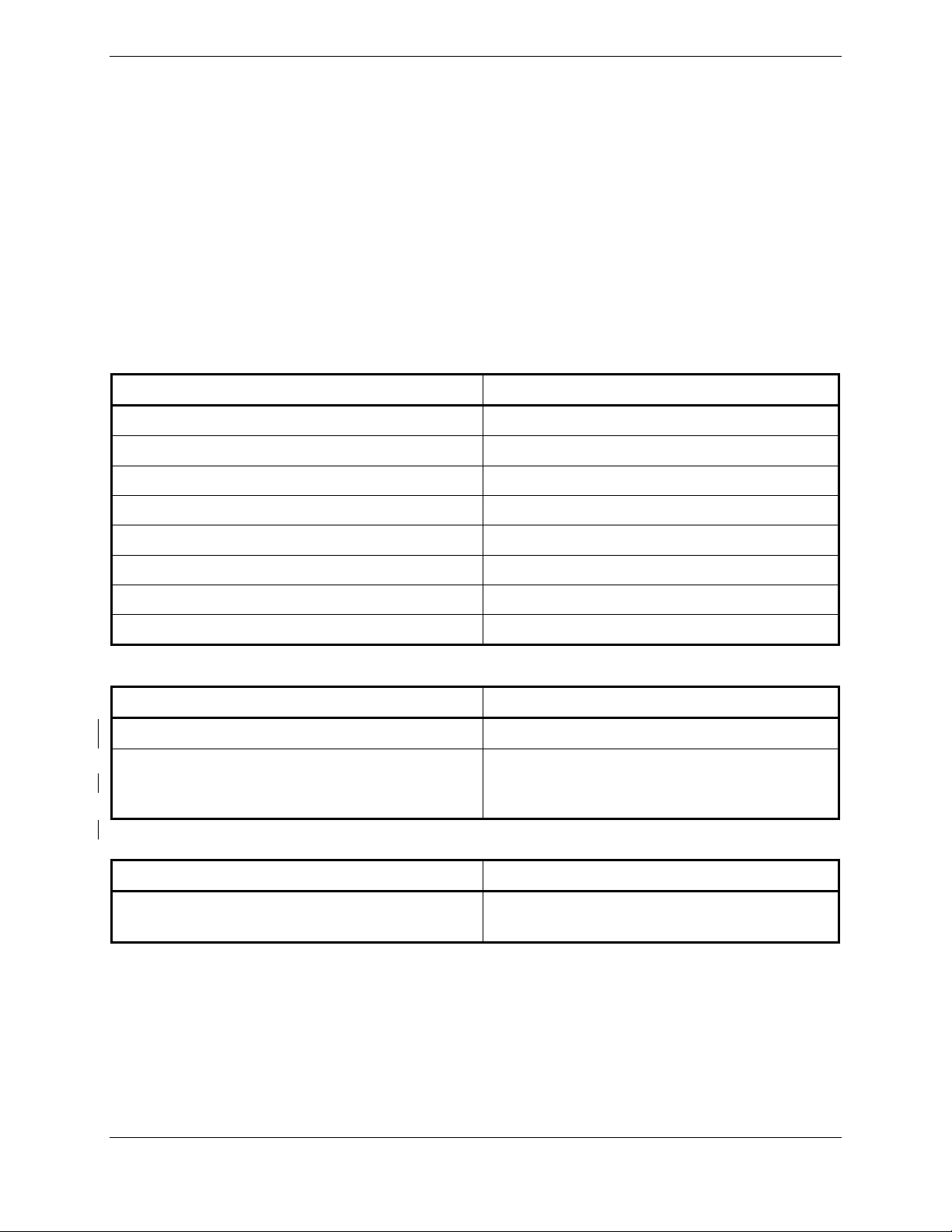
Connector Kits Garmin P/N
QMA Right Angle Connector Kit (4 pieces) 011-01364-00
QMA Straight Connector Kit (4 pieces) 011-01364-01
QMA Right Angle Connector Kit (1 piece) 011-01364-02
QMA Straight Connector Kit (1 piece) 011-01364-03
QMA Termination Connector Kit (4 pieces) 011-01364-04
GTS 8XX Connector Kit 011-01360-00
GPA 65 Circular Connector Kit 011-01365-00
USB-B Pigtail (non-G1000 installations only) 011-01782-00
Antennas Garmin P/N
GA 58 Directional Antenna, (011-01346-00) 010-10720-00*
Monopole Antenna 010-10160-00 or
L-Band Monopole Antenna that meets
TSO-C74c
*010-10720-00 includes mounting screws and o-ring, unless specifically requested to exclude.
Configuration Module Garmin P/N
Configuration Module (non-G1000 installations
only)
011-00979-20
Page 2-2 GTS 8XX/GPA 65 Installation Manual
Revision 4TP 190-00587-00
Page 21

2.2 Installation Considerations
Fabrication of a wiring harness is required. Sound mechanical and electrical methods and practices are
required for installation of the GTS 8XX/GPS 65.
2.2.1 Antenna Considerations
Antenna installations on pressurized cabin aircraft require FAA approved installation design and
engineering substantiation data whenever such antenna installations incorporate alteration (penetration) of
the cabin pressure vessel by connector holes and/or mounting arrangements. For needed engineering
support pertaining to the design and approval of such pressurized aircraft antenna installations, it is
recommended that the installer proceed according to any of the following listed alternatives:
1. Obtain approved antenna installation design data from the aircraft manufacturer.
2. Obtain an FAA approved STC, pertaining to, and valid for the antenna installation.
3. Contact the FAA Aircraft Certification Office in the appropriate Region and request identification
of FAA Designated Engineering Representatives (DERs) who are authorized to prepare and
approve the required antenna installation engineering data.
4. Obtain FAA Advisory Circular AC-183C and identify a DER from the roster of individuals in it.
5. Contact an aviation industry organization such as the Aircraft Electronics Association for
assistance.
For all composite aircraft, antenna installation requires that a ground plane be fabricated on the internal
surface of the aircraft directly under the antenna. The TAS/TCAS antenna pattern is dependent upon a
ground plane under the antenna. The minimum recommended antenna ground plane dimensions are
18” x 18” for composite aircraft.
A fabricated doubler plate assembly supplied by the installing agent or antenna vendor may be required
inside the fuselage to complete the antenna hardware installation.
NOTE
For all GTS 8XX installations, a monopole antenna is recommended if installing an
optional bottom mounted antenna on a fixed-gear aircraft, while retractable-gear aircraft
may use either a monopole or a directional bottom mounted antenna. The target bearing
accuracy may be degraded for bottom directional antenna installations on aircraft with
fixed gear.
GTS 8XX/GPA 65 Installation Manual Page 2-3
190-00587-00 Revision 4TP
Page 22

2.2.1.1 TAS/TCAS Antenna Location
To achieve proper interrogation and surveillance volumes the following GTS 8XX antenna installation
guidelines should be followed.
The GTS 8XX requires a top-mounted directional antenna. An optional bottom mounted directional or
L-band monopole antenna can be installed in conjunction with the top-mounted directional antenna.
Antenna locations are critical to maintain the surveillance coverage across all azimuth and elevation
angles. Locations shall be chosen so the top mounted and bottom mounted antenna will represent same
range and bearing to an intruder. The mounting location, geometry, and surroundings of the antenna can
affect the system performance. The following guidance provides information to aid the installer in
ensuring that the most optimum location is selected for the installation of the antenna. Because meeting
all of these installations guidelines may not be possible on all aircraft, these guidelines are listed in order
of importance to achieve optimum performance. The installer must use best judgment to balance the
installation guidelines.
Installations must be thoroughly tested to verify that performance degradation as a result of antenna
placement is not an issue for the TAS/TCAS system as well as other systems.
1. As far as physically possible, the top directional antenna shall be mounted at the most forward
location.
2. The TAS/TCAS antenna(s) shall be mounted on the aircraft skin so that the horizontal base is
horizontal to within +/-5° in longitudinal and lateral axes when the aircraft is in level flight.
3. The TAS/TCAS antenna(s) shall be mounted on a flat section of the fuselage to reduce the gap
formed between the base plate and the fuselage when normal mounting torque is applied.
4. It is recommended that all antennas be mounted at least 20 inches away (measured from center to
center) from the TAS/TCAS antenna(s).
5. Ground plane considerations shall include minimization of any discontinuities such as overlapped
un-riveted airframe skins, cowlings, or hatches. It is recommended that all such discontinuities be
at least 18 inches from the nearest edge of the TAS/TCAS antenna.
6. For installations using a bottom mounted antenna, it is recommended that the top and bottom
antennas be located near the same vertical line through the aircraft such that they represent the
same range and bearing to an intruder.
7. The top and bottom mounted TAS/TCAS Antenna shall be as close as possible to the aircraft
centerline.
8. It is recommended that no antenna be mounted in front of the TAS/TCAS antenna(s).
Page 2-4 GTS 8XX/GPA 65 Installation Manual
Revision 4TP 190-00587-00
Page 23

2.3 Electrical Bonding
Electrical equipment, supporting brackets, and racks should be electrically bonded to the aircraft’s main
structure. Refer to SAE ARP 1870 section 5 when surface preparation is required to achieve electrical
bond. The electrical bond should achieve direct current (DC) resistance less than or equal to 2.5
milliohms to local structure to where the equipment is mounted. Compliance should be verified by
inspection using a calibrated milliohm meter. An equivalent OEM procedure may also be substituted.
There may be OEM-specific reasons for electrically isolating equipment or having a higher bond
resistance. These reasons should be rationalized upon installation approval. In general, Garmin
recommends that all GTS 8XX equipment be electrically bonded.
The antenna ground plane and doubler plate must be electrically bonded to the antenna baseplate. The
electrical bond must achieve direct current (DC) resistance less than or equal to 2.5 milliohms.
For composite aircraft, the antenna baseplate must be electrically bonded to the common ground of other
installed equipment for lightning purposes. This can be achieved through the antenna mounting screws.
2.4 Cabling and Wiring
Use #24 AWG or larger diameter wire for all connections unless otherwise specified. The minimum
diameter wire size for all GTS 8XX installation wiring is #24 AWG, except in the case of Aircraft Power
and Aircraft Ground and both shall be a minimum of #18 AWG. Refer to Table 2-1 for GPA 65 wiring
specifications.
A single circuit breaker shall be dedicated to the GTS 8XX unless specifically approved by the
manufacturer on a case by case basis, or allowed by the STC. Do not attempt to combine more than one
unit on the same circuit breaker unless it is specified on an aircraft manufacturer approved drawing, or
STC documentation, for the specific installation requiring a combined configuration.
The current rating for each standard density 37-pin D-sub connector pin is 5 Amps, and the current rating
for each high density 78-pin D-sub connector pin is 2 Amps. A 14 Vdc installation requires a minimum
of two Aircraft Power and two Aircraft Ground wires in the harness. A 28 Vdc installation requires a
minimum of one Aircraft Power and one Aircraft Ground wires in the harness.
It is the responsibility of the installing agency to take into account wire sizing based on the length and
number of wires, current draw of the unit, D-sub connector pin current rating, and the unit’s internal
protection requirements.
NOTE
GTS 8XX/GPA 65 Installation Manual Page 2-5
190-00587-00 Revision 4TP
Page 24
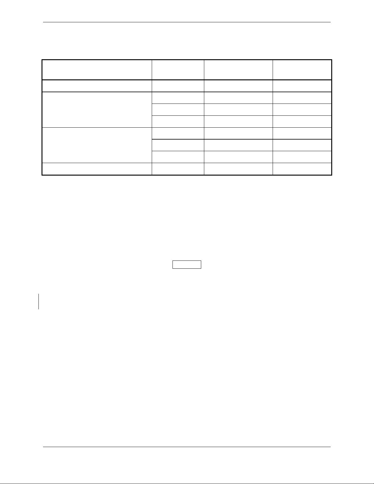
The maximum wiring length from the GTS 8XX to the GPA 65 is 45 feet.
Table 2-1. GPA 65 Minimum Wiring Requirements
Line
Number of
Pins/Wires
Length of Wire
Wire Gauge
Specification
+35V 2 Up To 45' #24 AWG
2 Up To 45' #24 AWG
+6V
1 Up To 30' #22 AWG
1 Up To 20' #24 AWG
2 Up To 45' #24 AWG
-5V
1 Up To 30' #22 AWG
1 Up To 20' #24 AWG
Ground 3 Up To 45' #24 AWG
The contacts used to facilitate the use of #18 AWG wire for Aircraft Power and Aircraft Ground have
expanded-diameter barrels that extend out from the back of the standard D-sub connector body to
accommodate the larger diameter wire. Appropriate heat shrink tubing should be utilized to provide
sufficient insulation from surrounding contacts.
Ensure that routing of the wiring does not come in contact with sources of heat, RF or EMI interference.
Check that there is ample space for the cabling and mating connectors. Avoid sharp bends in cabling and
routing near aircraft control cables.
NOTE
All appliance to antenna cabling shall bundle top channels as a group and bottom
channels as a group to prevent incorrect wiring between top and bottom channels.
A visual inspection shall be performed to verify that all coaxial cables are connected properly, before
attempting to operate the equipment.
Page 2-6 GTS 8XX/GPA 65 Installation Manual
Revision 4TP 190-00587-00
Page 25
2.4.1 Coaxial Cable
The GTS 800 requires two sets of coaxial cable assemblies and the GTS 820/850 requires three sets of
coaxial cable assemblies when a directional GA 58 antenna (or other Garmin approved antenna) is used
for both top and bottom. Each set consists of four coaxial cable assemblies.
Each set of four cables must be assembled using the same type of coaxial cable in order to meet phase and
attenuation matching requirements. In order for the system to operate in compliance with manufacturer
specifications, the coaxial cable assemblies must not exceed the attenuation specifications as stated in this
document. This section explains in further detail the coaxial cable and termination requirements.
2.4.1.1 GTS 800 Installations
NOTE
A monopole antenna is required if installing an optional bottom mounted antenna on all
fixed-gear aircraft. Retractable-gear aircraft can use either a monopole or a directional
bottom mounted antenna.
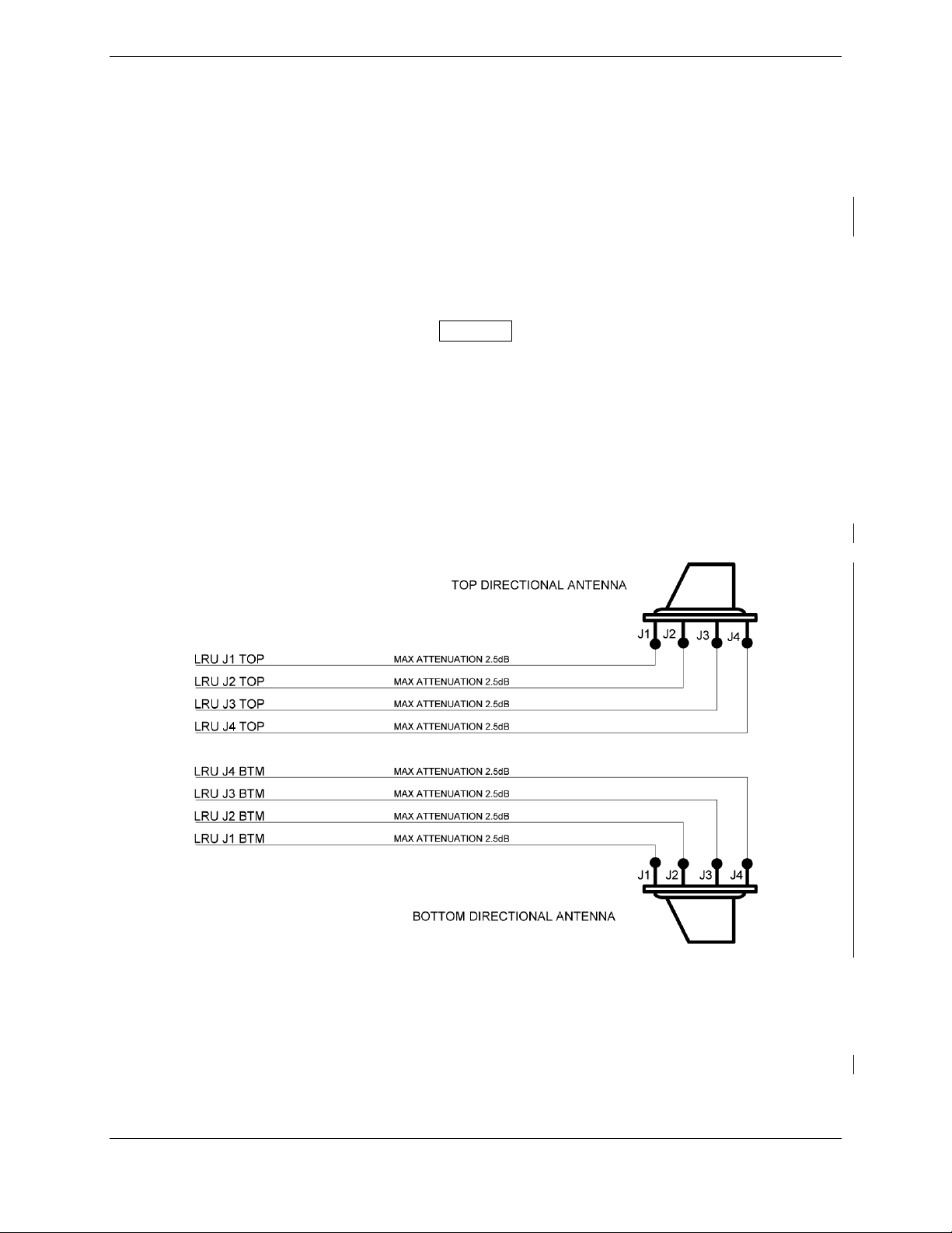
A GTS 800 installation with both top and bottom mounted directional antennas uses one set of coaxial
cables for the four GTS 800 TOP jacks (J1 TOP, J2 TOP, J3 TOP, J4 TOP) that are connected to the
corresponding top antenna jacks J1, J2, J3 and J4. A second set of coaxial cables are used for the four
GTS 800 BTM jacks (J1 BTM, J2 BTM, J3 BTM, J4 BTM) that are connected to the corresponding
bottom antenna jacks J1, J2, J3 and J4. Each cable assembly shall not exceed the maximum attenuation
of 2.5dB at 1090MHz as shown in Figure 2-1.
Figure 2-1. GTS 800 Installation with Top and Bottom Directional Antennas
If an optional bottom mount monopole antenna is installed, a single coaxial cable must be used to connect
the GTS 800 bottom jack J1 BTM to the monopole antenna jack. The coaxial cable assembly shall not
exceed the maximum attenuation of 2.5dB at 1090MHz as shown in Figure 2-2 and stated in Table 2-4.
Each of the remaining GTS 800 bottom jacks (J2 BTM, J3 BTM, J4 BTM) are to be terminated using a
QMA 2 watt termination as specified in Table 2-2.
GTS 8XX/GPA 65 Installation Manual Page 2-7
190-00587-00 Revision 4TP
Page 26
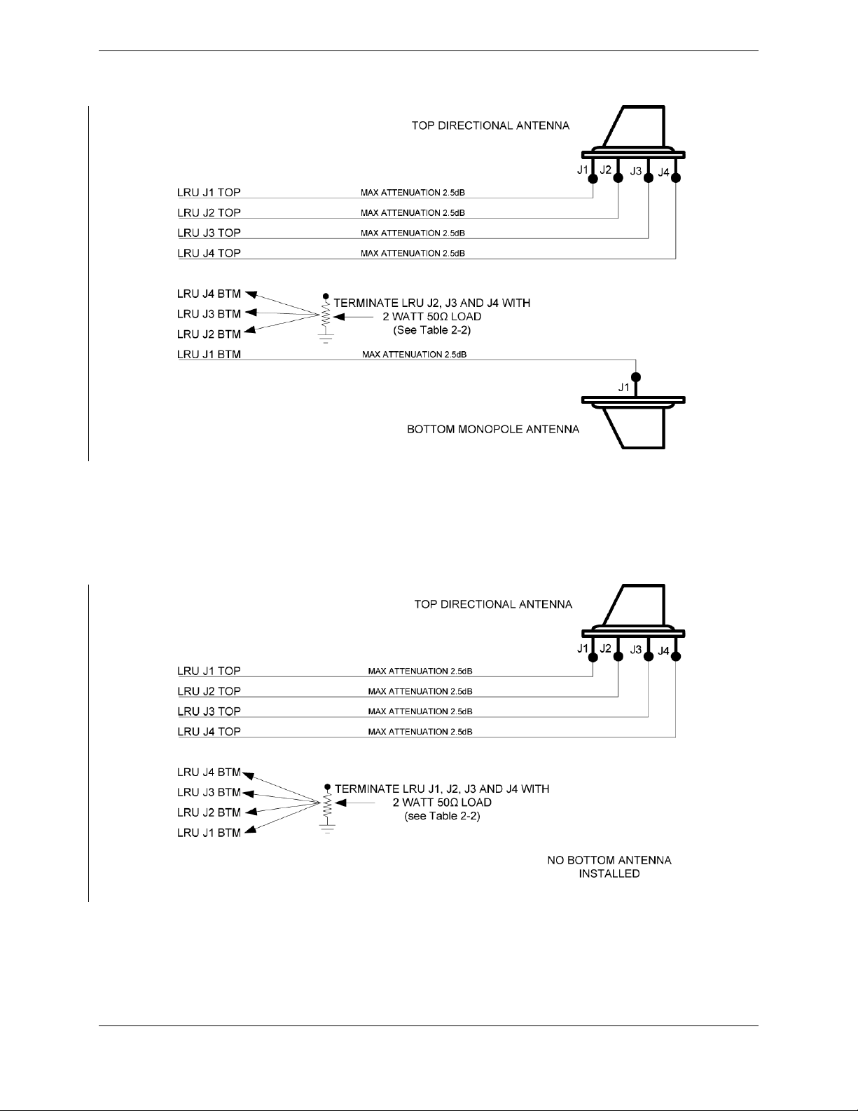
Figure 2-2. GTS 800 Installation with Top and Bottom Monopole Antennas
If no bottom mount antenna is installed, each of the GTS 800 bottom jacks (J1 BTM, J2 BTM, J3 BTM
and J4 BTM) must be terminated with a QMA 2 watt termination as specified in Table 2-2 and shown in
Figure 2-3.
Figure 2-3. GTS 800 Installation with Top Directional Antennas and No Bottom Antenna
Page 2-8 GTS 8XX/GPA 65 Installation Manual
Revision 4TP 190-00587-00
Page 27
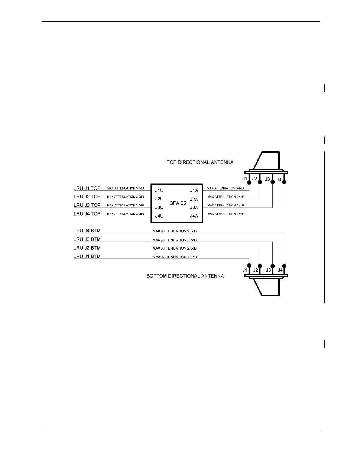
2.4.1.2 GTS 820 and GTS 850 Installations
GTS 820 and GTS 850 installation with both top and bottom mount directional antennas use one set of
coaxial cables for the four GTS 820 or GTS 850 TOP jacks (J1 TOP, J2 TOP, J3 TOP, J4 TOP) that are
connected to the corresponding GPA 65 processor unit jacks (J1U, J2U, J3U, J4U).
Each top cable assembly shall not exceed the maximum attenuation of 3.0dB at 1090MHz as shown in
Figure 2-4 and stated in Table 2-3. Each bottom cable assembly shall not exceed the maximum
attenuation of 2.5dB at 1090MHz as shown in Figure 2-4 and stated in Table 2-3.
A second set of coaxial cables are used to connect the four GPA 65 antenna jacks (J1A, J2A, J3A, J4A) to
the corresponding top antenna jacks (J1, J2, J3, J4). Each cable assembly shall not exceed the maximum
attenuation of 0.4dB at 1090MHz as shown in Figure 2-4 and stated in Table 2-3. A third set of coaxial
cables are used to connect the four LRU BTM jacks (J1 BTM, J2 BTM, J3 BTM, J4 BTM) to the
corresponding bottom antenna jacks (J1, J2, J3, J4). Each cable assembly shall not exceed the maximum
attenuation of 2.5dB at 1090MHz as shown in Figure 2-4.
Figure 2-4. GTS 820 and GTS 850 Installation with Top and Bottom Directional Antenna
If an optional bottom mount monopole antenna is installed, a single coaxial cable must be used to connect
the GTS 820 or GTS 850 J1 BTM jack to the monopole antenna jack. The cable assembly shall not
exceed the maximum attenuation of 2.5dB at 1090MHz as shown in Figure 2-5 and stated in Table 2-3.
Each of the remaining GTS 820 or GTS 850 bottom jacks (J2 BTM, J3 BTM, J4 BTM) are to be
terminated using a QMA 2 watt termination as specified in Table 2-2.
GTS 8XX/GPA 65 Installation Manual Page 2-9
190-00587-00 Revision 4TP
Page 28
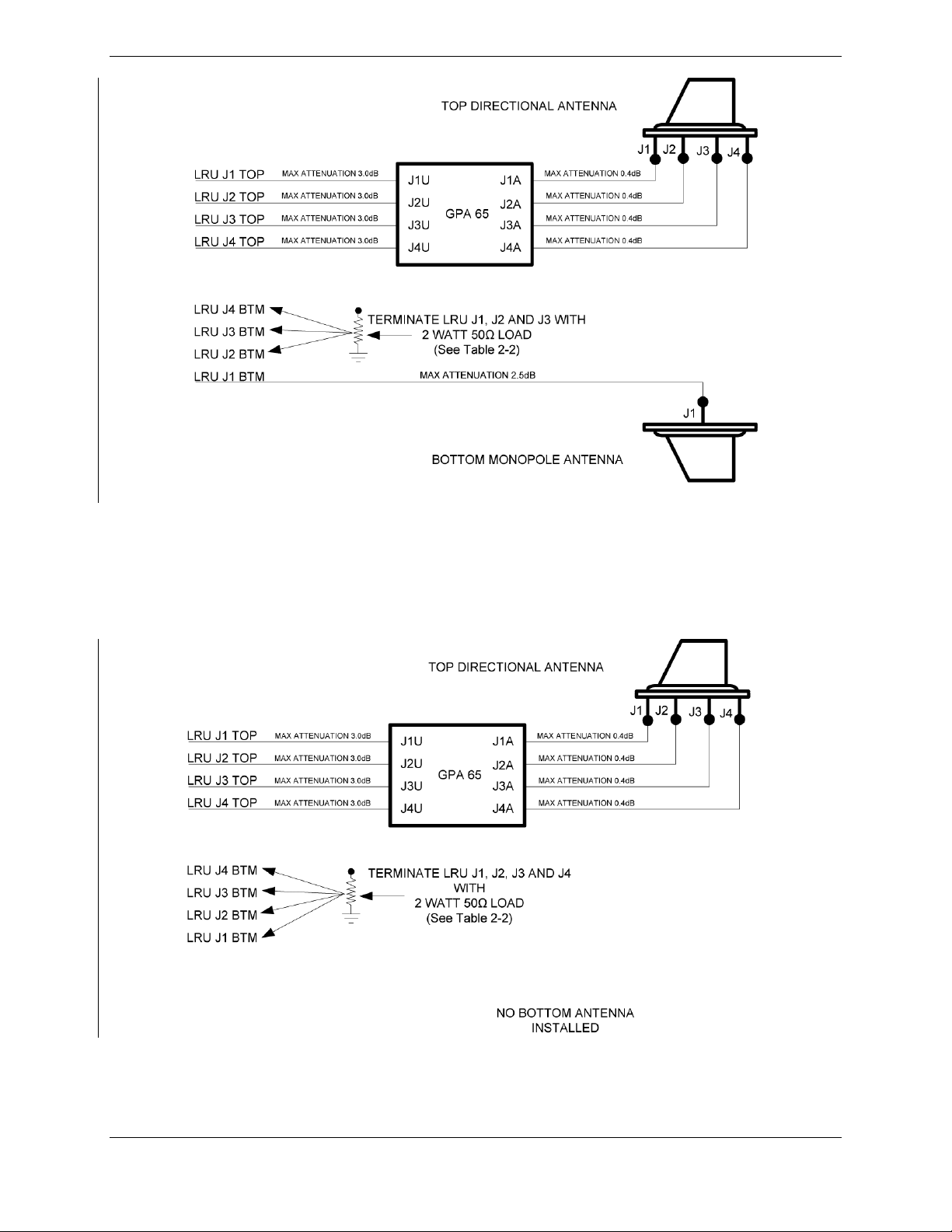
Figure 2-5. GTS 820 and GTS 850 Installation with Top Directional and Bottom Monopole
Antenna
If no bottom mount antenna is installed, each of the GTS 820 or GTS 850 bottom jacks (J1 BTM, J2
BTM, J3 BTM and J4 BTM) shall be terminated with a QMA 2 watt termination as specified in Table 2-2
and shown in Figure 2-6.
Figure 2-6. GTS 820 and GTS 850 Installation with Top Directional and No Bottom
Antenna
Page 2-10 GTS 8XX/GPA 65 Installation Manual
Revision 4TP 190-00587-00
Page 29
NOTE
Any QMA terminations used other than those specified in Table 2-2 will constitute the
installation as being non-compliant with the manufacturer’s installation standards.
2.4.1.3 Fabrication of Coaxial Cable Assemblies
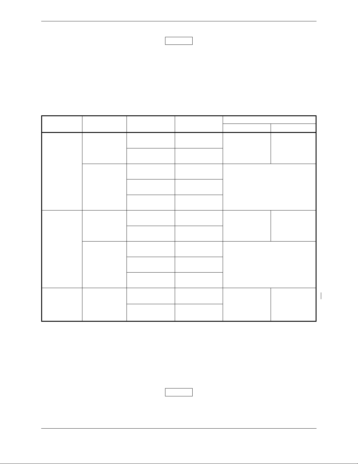
The installing agency may fabricate cable assemblies by terminating either M17/128-RG400 or
M17/60-RG142 coaxial cable with available QMA connector kits. Table 2-2 lists recommend cable types
to be used with specified QMA connectors for the GTS 8XX.
Table 2-2. Cable Types and QMA Connectors
Connector
Type
QMA Right
Angle
QMA
Straight
Cable Type Manufacturer
RG 400,
RG 142,
ECS 311901
ECS 311501,
ECS 311601,
ECS 421601,
PIC S67163
RG 400,
RG 142,
ECS 311901
ECS 311501,
ECS 311601,
ECS 421601,
PIC S67163
Amphenol 930-189P-51A
Garmin 330-00500-00
Amphenol 930-191P-51A
ECS 930-191P-51A
PIC 110477
Amphenol 930-192P-51S
Garmin 330-00500-01
Amphenol 930-190P-51S
ECS 930-190P-51S
PIC 110476
Connector
Part Number
Garmin Order Number
4 Piece Kit 1 Piece Kit
011-01364-00 011-01364-02
N/A
011-01364-01 011-01364-03
N/A
QMA 50
Load
Termination
N/A
Amphenol 930-187P-51T
011-01364-04 N/A
Garmin 330-00500-02
The recommended coaxial cable lengths in Table 2-3 are for reference only. Along with standard MIL-C17/128-RG400 or MIL-C-17/60-RG142, Table 2-3 lists recommended antenna cable vendors along with
the cable type that each specific vendor offers. The recommended coaxial cable lengths are defined as the
end to end length of a non-terminated coaxial cable. The attenuation values listed in Table 2-3 include
the maximum attenuation of both the maximum length of coaxial cable and two RF coaxial connectors at
a frequency of 1090 MHz. It is the installing agencies responsibility to ensure that the coaxial cable
assemblies built meet the manufacturer’s attenuation specifications in order to comply with the
manufacturer’s installation standards.
NOTE
Any in-line or bulkhead penetrations must be evaluated separately. It is the installing
agency’s responsibility to show airworthiness of the installed fabricated or purchased
coaxial cable assemblies.
GTS 8XX/GPA 65 Installation Manual Page 2-11
190-00587-00 Revision 4TP
Page 30
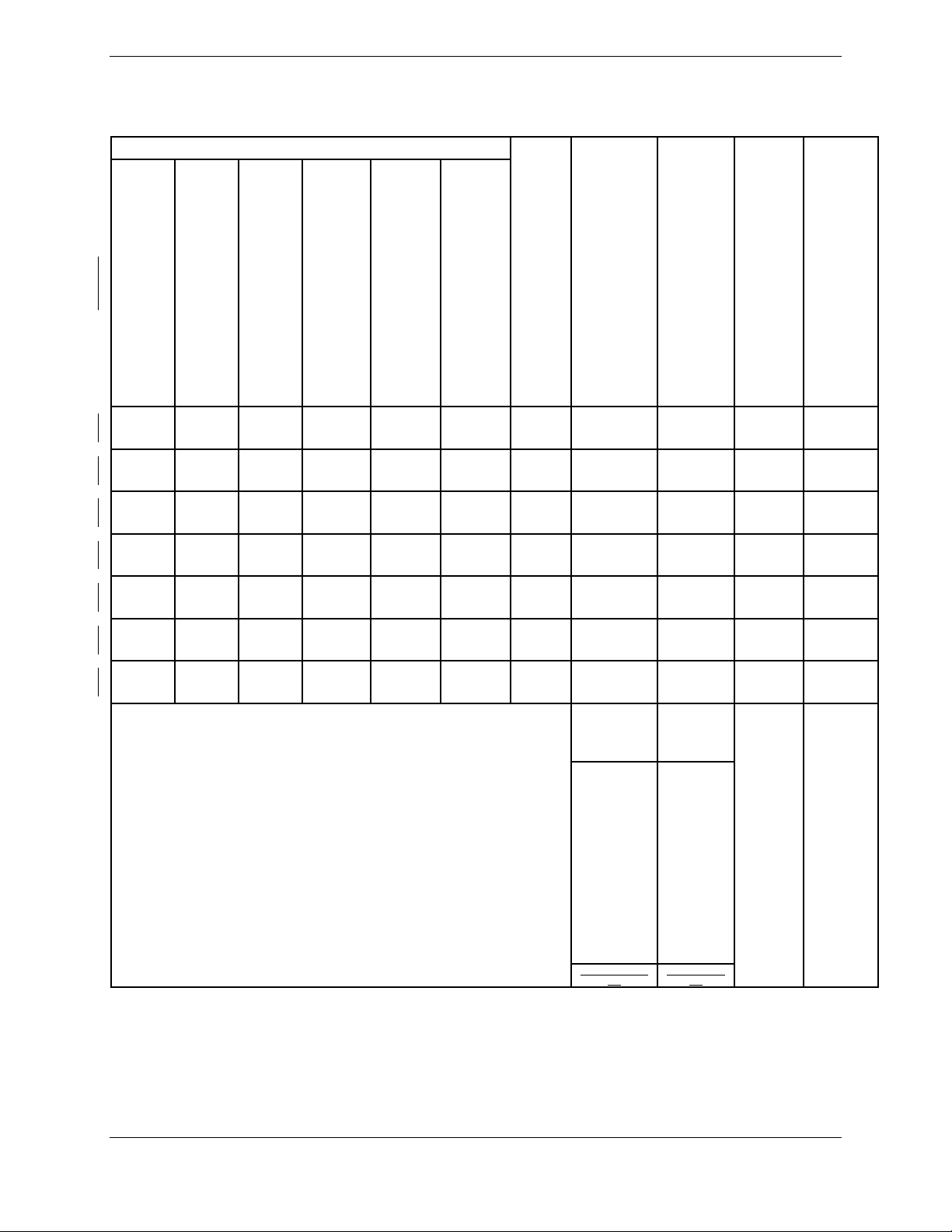
Table 2-3. Recommended Coaxial Length
Attenuation
Loss
of
0.4 dB
1' 10"
[0.55m]
2' 0"
[0.60m]
2' 5"
[0.74m]
3' 3"
[0.99m]
3' 5"
[1.04m]
4' 2"
[1.27m]
4' 0"
[1.21m]
Loss
of
0.5 dB
2' 7"
[0.79m]
2' 9"
[0.84m]
3' 4"
[1.02m]
4' 6"
[1.37m]
4' 6"
[1.37m]
5' 7"
[1.70m]
5' 5"
[1.60m]
Loss
of
1.5 dB
9' 0"
[2.74m]
10' 5"
[2.94m]
11' 6"
[3.50m]
15' 8"
[4.77m]
16' 1"
[4.90m]
19' 8"
[5.99m]
18' 5"
[5.61m]
Loss
of
2.0 dB
12' 0"
[3.66m]
13' 0"
[3.96m]
15' 5"
[4.70m]
21' 0"
[6.40m]
21' 5"
[6.55m]
26' 5"
[8.05m]
25' 0"
[7.62m]
Supplier Information
Loss
of
2.5 dB
15' 5"
[4.70m]
16' 6"
[5.03m]
19' 6"
[5.94m]
26' 8"
[8.13m]
27' 6"
[8.38m]
33' 5"
[10.19m]
31' 6"
[9.60m]
Loss
of
3.0 dB
18' 8"
[5.68m]
20' 1"
[6.12m]
23' 10"
[7.26m]
32' 7"
[9.93m]
33' 6"
[10.21m]
40' 10"
[12.44m]
38' 3"
[11.65m]
Attenuation
15.5
14.45
12.16
8.93
8.7
7.12
7.5
(dB/100ft)
ECS Type
311901
421601
311601
311501
S67163
Vendor:
Electronic
Cable
Specialists
5300 W.
Franklin
Drive
Franklin, WI
53132
Tel: 800327-9473
414-4215300
Fax: 414421-5301
www.ecsdirect.c
om
PIC Type
Vendor:
PIC Wire
and Cable
N53
W24747
S
Corporate
Circle
Sussex,
WI 530890330
Tel: 800742-3191
262-2460500
Fax: 262246-0450
www.picwire.c
om
M17/128
-RG400
M17/60-
RG142
M17/127
-RG393
See
current
issue of
Qualified
Products
List
QPL-17.
RG Type
MIL-C-17 Type
RG-400
RG-142
RG-393
RG types
are
obsolete
and are
shown for
reference
only;
replaced
by M17
type
numbers.
Page 2-12 GTS 8XX/GPA 65 Installation Manual
Revision 4TP 190-00587-00
Page 31
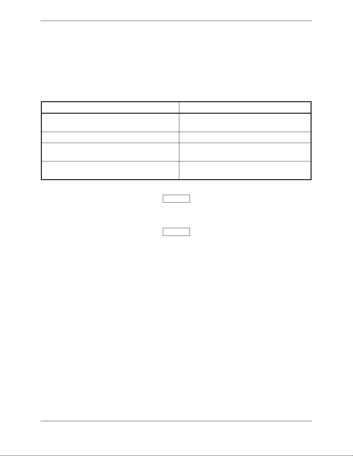
The coaxial cable lengths in each coaxial cable assembly set used to connect the GTS 800 TOP and
BOTTOM jacks to the top and bottom antenna jacks, the TOP GTS 820 or GTS 850 jacks to the GPA 65
jacks, and the BOTTOM GTS 820 or GTS 850 jacks to the directional antenna jacks, shall be within 2
inches of each other.
The coaxial cable assembly lengths in each coaxial cable assembly set between the GPA 65 jacks and
directional antenna jacks for the GTS 820 or GTS 850 shall be within 0.25 inches of each.
Table 2-4. Coaxial Cable Set Length Tolerance
Coaxial Cable Set Length Tolerance*
GTS 800 TOP/BOTTOM to top and bottom
2" of each other
antenna
GTS 820 and/or 850 TOP to GPS 65 2" of each other
GTS 820 and/or GTS 850 BOTTOM to
directional antenna
GPA 65 to directional antenna (for the GTS
820 and/or GTS 850
2" of each other
0.25" of each other
* Ensure cables do not exceed the maximum lengths as stated in Table 2-3.
NOTE
It is recommended that a color band be placed on both ends of each cable to match the
color marking designating the mating jack connector.
NOTE
It is recommended that the nominal end to end coaxial cable (non-terminated) length for
each set be recorded for the specific installation in the event that a particular coaxial
cable assembly associated with an installed set should require replacement.
GTS 8XX/GPA 65 Installation Manual Page 2-13
190-00587-00 Revision 4TP
Page 32
2.4.1.4 Coaxial Cable Assembly Instructions
The following assembly instructions apply to coaxial cables assemblies using QMA connectors specified
in Table 2-2 for use with RG-400 or RG-142 cable types:
1. Slide the heat shrink sleeve and crimp ferrule onto the cable.
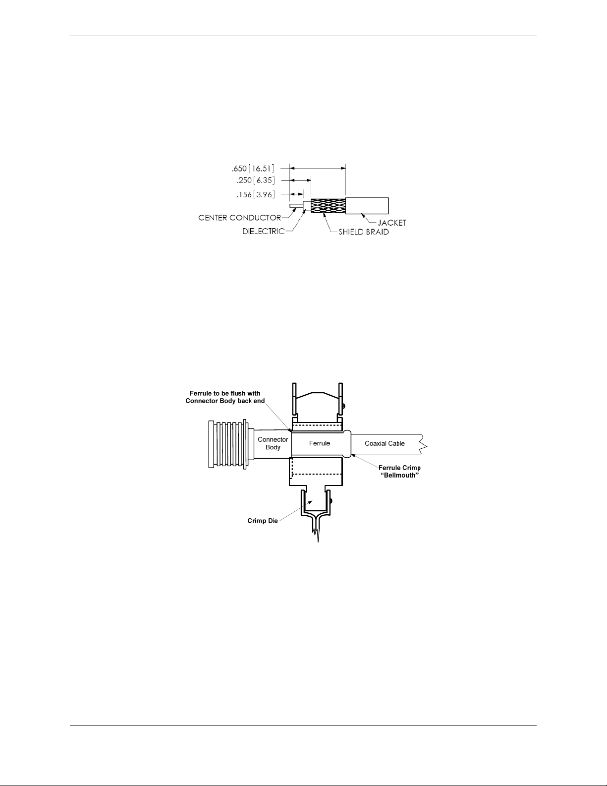
2. Strip the cable to the dimensions shown in Figure 2-7.
Figure 2-7. RG-400/RG-142 Coaxial Cable Stripping Dimensions
3. Slide the center contact onto the center conductor of the cable. Ensure the center conductor of the
cable is visible through the inspection hole of the center contact and crimp using Tyco tool
354940-1 and die assembly 220189-3, or Tyco tool 354940-1 and die assembly 91901-1, or Tyco
tool 69478-1.
4. Expand the shielding braid and insert the crimped center contact into the connector body until the
cable dielectric is flush with the dielectric inside the connector body. Insure the shield braid does
not enter the connector body.
Figure 2-8. Ferrule and Crimp Die Positioning
5. Slide the crimp ferrule over the shielding braid to the back of the connector body. Position the
crimp tool flush with the back of the connector body and crimp using Tyco tool 35940-1 and die
assembly 220189-3, or Tyco tool 354940-1 and die assembly 91901-1, or Tyco tool 69478-1.
The crimp tool should be positioned such that a “bellmouth” (see figure 2-8) is present in the
crimp ferrule on the coaxial cable side of the crimp after crimping.
6. Slide heat shrink sleeve to back of connector body and shrink in place. Ensure that the heat
shrink does not protrude past the connector body back end once it is shrunk into place. It is
recommended that the color-coded heat shrink tubing provided in the kit be used.
Page 2-14 GTS 8XX/GPA 65 Installation Manual
Revision 4TP 190-00587-00
Page 33
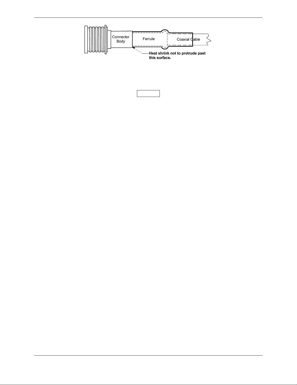
Figure 2-9. Heat Shrink Positioning
NOTE
Use of QMA connectors other than those specified in Table 2-2 for coaxial cable
assemblies fabricated by the installing agency using either M17/128-RG400 or
M17/60-RG142 coaxial cable will constitute the cable assemblies as being
non-compliant with the manufacturer’s installation standards.
2.4.1.5 Coaxial Cable Assem bly Repair and Rework
In the event that an individual coaxial cable assembly requires rework, between a GTS 800 jack and
antenna jack, a TOP GTS820/850 jack and GPA 65 jack or a BTM GTS 820/850 jack and antenna jack,
the repairable coaxial cable may be reduced in length a maximum of two inches.
In the event that rework is required on a coaxial cable assembly between a GPA 65 jack and antenna jack
on a GTS 820/850 installation, complete replacement of the cable assembly shall be required in lieu of
rework.
Refer to Table 2-3 for recommended maximum cable assembly lengths for cable assemblies fabricated by
the installer.
2.5 Cooling Requirements
The GTS 8XX and GPA 65 meet all TSO requirements without external cooling. A 5/8” diameter air
fitting is provided on the rear of the GTS 8XX for the purpose of admitting cooling air if desired. If a
form of forced air cooling is installed, make certain that rainwater cannot enter and be sprayed on the
equipment.
For G1000 installations refer to the G1000 System Installation manual, Garmin part number
190-00303-00, for more information on cooling requirements.
GTS 8XX/GPA 65 Installation Manual Page 2-15
190-00587-00 Revision 4TP
Page 34
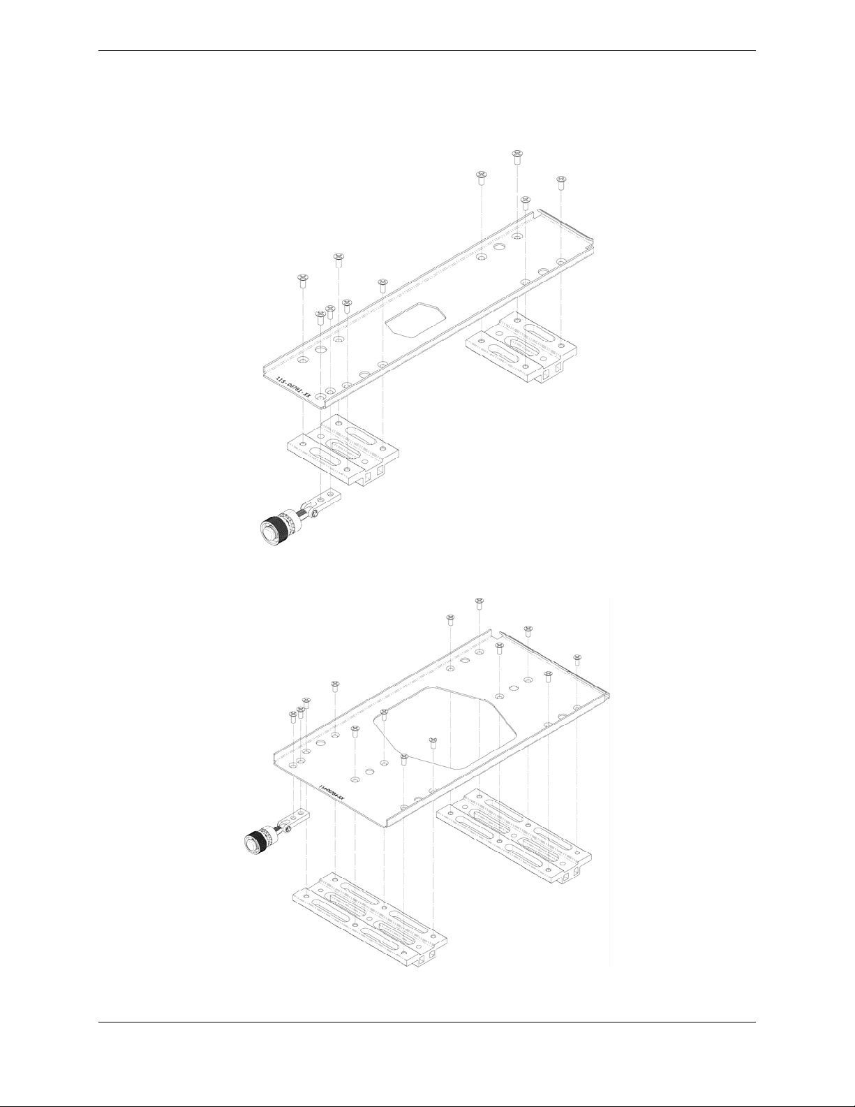
2.6 Mounting Requirements
The GTS 8XX can be mounted vertically or horizontally using the installation racks shown below. Refer
to Appendix A for outline and installation drawings.
Figure 2-10. GTS 8XX Vertical Installation Rack (Garmin P/N115-00781-00)
Figure 2-11. GTS 8XX Horizontal Installation Rack (Garmin P/N115-00784-00)
Page 2-16 GTS 8XX/GPA 65 Installation Manual
Revision 4TP 190-00587-00
Page 35
3 INSTALLATION PROCEDURE
3.1 Unpacking Unit
Carefully unpack the equipment and make a visual inspection of the unit for evidence of damage incurred
during shipment. If the unit is damaged, notify the carrier and file a claim. To justify a claim, save the
original shipping container and all packing materials. Do not return the unit to Garmin until the carrier
has authorized the claim. Retain the original shipping containers for storage. If the original containers
are not available, a separate cardboard container should be prepared that is large enough to accommodate
sufficient packing material to prevent movement.
3.2 Wiring Harness Installation
Allow adequate space for installation of cables and connectors. The installer shall supply and fabricate all
of the cables. All electrical connections are made through two 78-pin high-density D subminiature
connectors, one 37-pin standard density connector, and one 19-pin circular connector (GTS 820 and
GTS 850 only). Section 4 defines the electrical characteristics of all input and output signals. Required
connectors and associated hardware are supplied with the connector kit.
See Appendix B for examples of interconnect wiring diagrams. Construct the actual harness in
accordance with aircraft manufacturer authorized interconnect standards.
Table 3-1. Socket and Pin Contact Part Numbers
78 Pin High Density D-Subminiature Connectors P8001 & P8002
37 Pin Standard Density D-Subminiature Connector P8003
19 Pin Circular Connector P651
Manufacturer
High Density Pin
(P8001 & P8002)
Garmin P/N 336-000 21-00 336-00022-00 N/A 336-00023-00
Military P/N M39029/58 -360 M39029/63-368 M39029/5-115 N/A
Positronic * * * FC6018D
AMP * 205090-1 * *
ITT Cannon * 031-1007-042 * 031-1007-054**
*Identify manufacturer part number by MIL SPEC identification
** Use only positioner part numbers ITT Cannon 980-0005-722, Astro Tools 616245 a nd Daniels MFG K250
Standard
Socket
(P8003)
Circular
Connector
Socket
(P651)
Standard Socket
(P8003)
Table 3-2. Socket Contact MIL SPEC M39029/5-115 Crimp Tooling
Manufacturer
Hand Crimping
Tool
Positioner
Insertion/Extraction
Tool
Tools Option 1
Military P/N M22520/1-01
Daniels
AF8 TH1A M81969/14-11*
M22520/1-02 M81969/14-11*
Tools Option 2
Military P/N M22520/2-01
Daniels
* Indicates plastic insertion/extraction tool
AFM8 K1S M81969/14-11*
M22520/2-02 M81969/14-11*
GTS 8XX/GPA 65 Installation Manual Page 3-1
190-00587-00 Revision 4TP
Page 36
Table 3-3. Pin Contact GPN 336-00021-00 MIL SPEC M39029/58-360 Crimp Tooling
Manufacturer
Military P/N M22520/2-01 M22520/2-09 M81969/1-04
Daniels AFM8 K42 M81969/1-04
Positronics 9507 9502-4 M81969/1-04
ITT Cannon 995-0001-584 M22520/2-09
Tyco-AMP 601966-1 601966-6
Astro 615717 615725 M81969/1-04
Amphenol 9507 9502-4 M81969/1-04
* Indicates plastic insertion/extraction tool
Hand Crimping
Tool
Positioner
Insertion/Extraction
Tool
274-7048-000*
MIL SPEC M81969/14-01
91067-1
MIL SPEC M81969/1-04
Table 3-4. Pin Socket Contacts GPN 336-00022-00 MIL SPEC M39029/63-368 and GPN
336-00023-00 Crimp Tooling
Manufacturer
Hand
Crimping
Tool
22 AWG Socket Contact
GPN 336-00022-00
(M39029/63-368)
Positioner
Insertion/Extraction
Tool
18 AWG Socket Contact
GPN 336-00023-00
Positioner
Insertion/Extraction
Tool
Military P/N M22520/2-01 M22520/2-08 M81969/1-02 N/A M81969/1-02
Daniels AFM8 K13-1 M81969/1-02 K774 M81969/1-02
Positronics 9507 9502-5 M81969/1-02 9502-11 M81969/1-02
980-0005-722**
ITT Cannon 995-0001-584 995-0001-604 980-2000-426*
Tyco-AMP 601966-1 601966-5
ASTRO 615717 615724 M81969/1-02 616245** N/A
Amphenol 9507 N/A N/A 9502-11 M81969/1-02
* Indicates plastic insertion/extraction tool
** Use only positioner part numbers ITT Cannon 980-0005-722, Astro Tools 616245 a nd Daniels MFG K250 for
contact part number ITT Cannon 031-1007-001
91067-2 or
M81969/1-02
or
Daniels K250**
N/A N/A
N/A
Page 3-2 GTS 8XX/GPA 65 Installation Manual
Revision 4TP 190-00587-00
Page 37
NOTES
1. Non-Garmin part numbers shown are not maintained by Garmin and consequently are subject
to change without notice.
2. Extracting a contact used for #18 AWG requires that the wire barrel be cut off from the
contact. It may also be necessary to push the pin out from the face of the connector when using
and extractor due to the absence of the wire. A new contact must be used when reassembling
the connector.
3. Contacts for #16 AWG and Contact Crimp Tooling: Contact Garmin for information regarding
contacts and contact crimp tooling. Note 2 also applies.
4. Alternate Contacts for Use With #18 AWG: As an alternative to the Positronic contacts listed,
and provided in the installation kit, if the need arises the installer may use contacts made by
ITT Cannon under P/N 031-1007-001. The particular contact is not compatible with the
Daniels MFG K774, Positronics 9502-11 or Amphenol 9502-11 positioners, though. Only use
postioner part numbers Daniels MFG K250, ITT Cannon 980-0005-722 and Astro 616245.
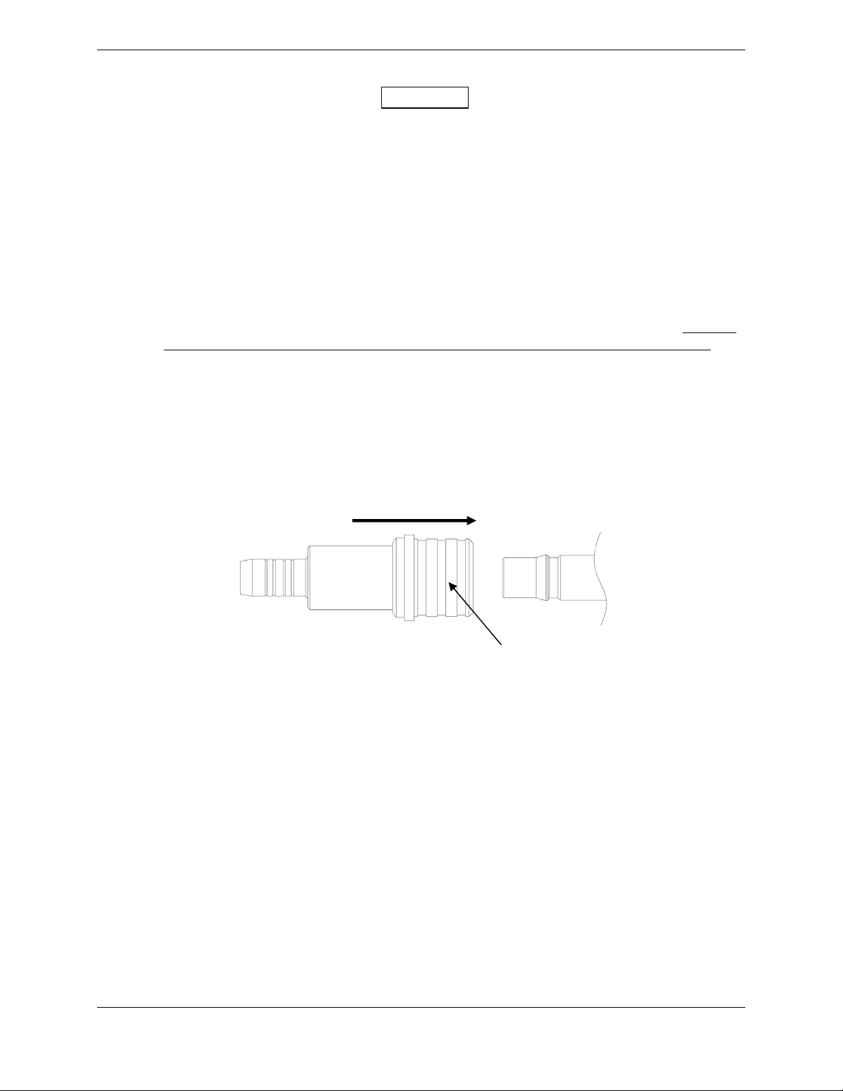
3.3 QMA Connector Insertion and Removal
To engage the QMA connectors, use the outer sleeve of the QMA plug to align the connectors and insert
the plug onto the jack until it snaps into place. There will be an audible “snap” when the connectors are
fully engaged, refer to Figure 3-1. No tools are required for the insertion of a QMA plug onto a QMA
jack.
Engage
Outer Sleeve
Figure 3-1. Engaging QMA Connectors
GTS 8XX/GPA 65 Installation Manual Page 3-3
190-00587-00 Revision 4TP
Page 38
CAUTION
Do not pull on the cable when removing the QMA plug from the jack.
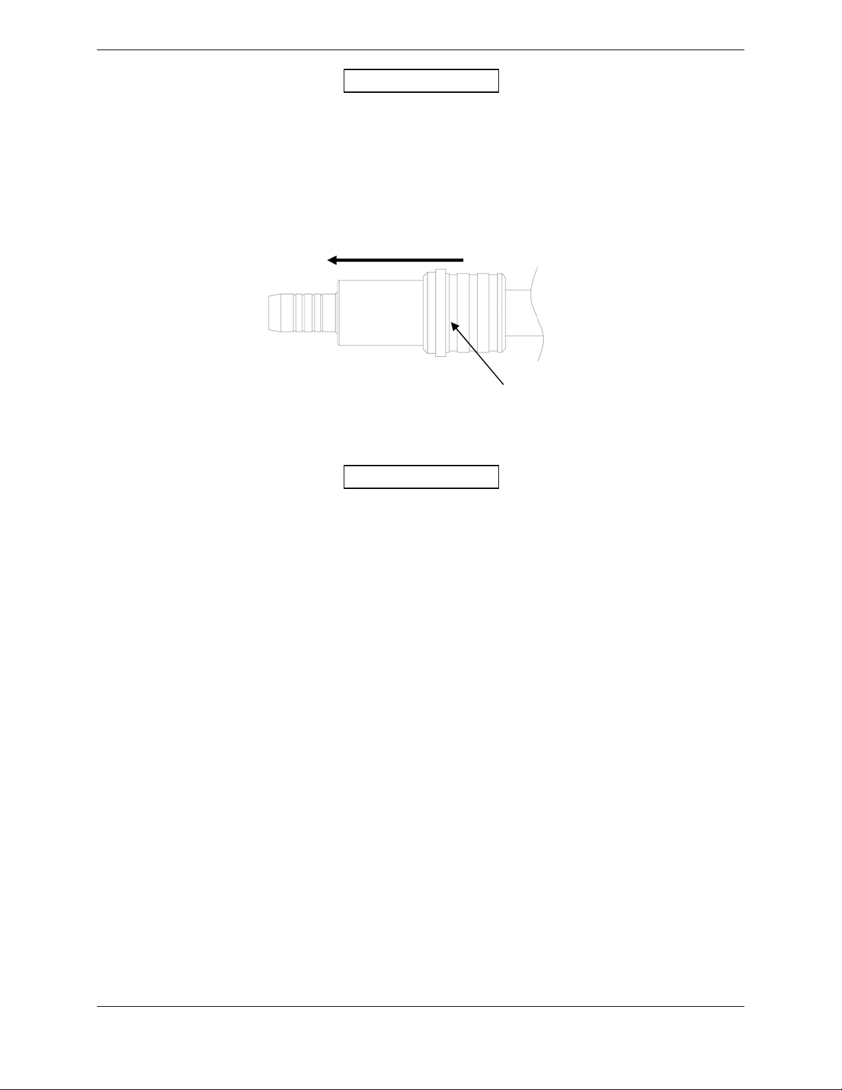
To disengage the QMA connectors, pull back firmly on the outer sleeve of the QMA plug away from the
jack connector (refer to Figure 3-2). This will disengage the locking mechanism that secures the plug
connector to the jack connector. Pulling on or disengaging the QMA connectors in any other way is not
recommended and may cause damage to both the connectors and coaxial cable.
Disengage
Figure 3-2. Disengaging QMA Connectors
Outer Sleeve
CAUTION
Side-loading of the QMA connectors should be avoided during both the insertion and
removal of the connectors. It is recommended service loops with adequate length of
coaxial cable be used to insure that side-loading on the connectors is minimized once the
cable is securely fastened in the aircraft. Excessive side-loading may result in damage or
premature failure of the QMA connectors.
Page 3-4 GTS 8XX/GPA 65 Installation Manual
Revision 4TP 190-00587-00
Page 39

3.4 Backshell, Pigtail Circular Connector, and Configuration Module
Assemblies
The GTS 8XX connector kits includes three Garmin backshell assemblies. The backshell assembly
houses the configuration module, if applicable. Garmin’s backshell also gives the installer the ability to
easily terminate shield grounds at the backshell housing.
Refer to the Jackscrew Backshell Installation Instructions (Garmin part number 190-00313-11) for
backshell assembly instructions.
Refer to the GPA 65 Pigtail Circular Connector Installation Instructions (Garmin part number
190-00313-XX) for pigtail assembly instructions.
Refer to the Jackscrew Configuration Module Installation Instructions (Garmin part number
190-00313-10) for configuration module assembly instructions.
3.5 Unit Installation
Refer to the outline and installation drawings shown in Appendix A of this manual
GTS 8XX/GPA 65 Installation Manual Page 3-5
190-00587-00 Revision 4TP
Page 40

3.5.1 Post Installation Configuration & Checkout
Before beginning the installation calibration, the installer must perform a visual inspection to verify the
coaxial cables are installed correctly based upon the system and antenna configuration.
NOTE
Tests performed with a ramp tester should be performed away from buildings that may
reflect the signal. Local air traffic control should be advised if the ramp tester has an
altitude programmed into it that may cause interaction with other TCAS-equipped traffic.
The following actions need to be performed after the equipment is installed:
1. GTS 8XX Configuration Options
2. CDTI (Cockpit Display of Traffic Information) Display setup and configuration
3. Calibration
4. Self test
5. Ramp test and return to service tests
6. Antenna verification
3.5.2 GTS 8XX Configuration Options
GTS 8XX Configuration is performed using a computer (installed with Microsoft Windows XP or later)
and the GTS 8XX Install Tool, Garmin part number 006-A0242-00. The tool is available for download
from the Dealers Only portion of the Garmin website (www.garmin.com).
G1000 Installations:
When installed as part of the G1000 integrated flight deck, the GTS 8XX must have FAA approved
configuration data. Configuration data is loaded to the GTS 8XX from an aircraft-specific G1000
software loader card.
For basic configuration information refer to the G1000 Line Maintenance and Configuration Manual
(190-00303-04), G1000 System Maintenance Manual LJ/VLJ (190-00903-00), or the G1000 System
Maintenance Manual Standard Piston/Turboprop Aircraft (190-00907-00). For actual
installation/checkout, use only aircraft manufacturer approved or STC checkout procedures.
Non-G1000 Installations:
Configuration and software uploading is accomplished by using a computer (installed with Microsoft
Windows XP or later) and the GTS 8XX Install Tool. An optional USB pigtail installed in the wiring
harness may be used.
The GTS 8XX Install Tool allows for configuration, diagnostics, and upload of GTS 8XX software.
The following GTS 8XX modes are accessible with the GTS 8XX Install Tool.
• Normal Mode – Allows selection of Traffic Mode to Standby, Operate, or Test. Reports
System Faults, Status Flags, and Operating Status. Allows Ground Test Mode to be
Enabled or Disabled.
• Configuration Mode – Allows selection of installation options
• Upload Mode – Allows upload of software to GTS 8XX unit
• Debug Mode – Runs system diagnostics
Page 3-6 GTS 8XX/GPA 65 Installation Manual
Revision 4TP 190-00587-00
Page 41
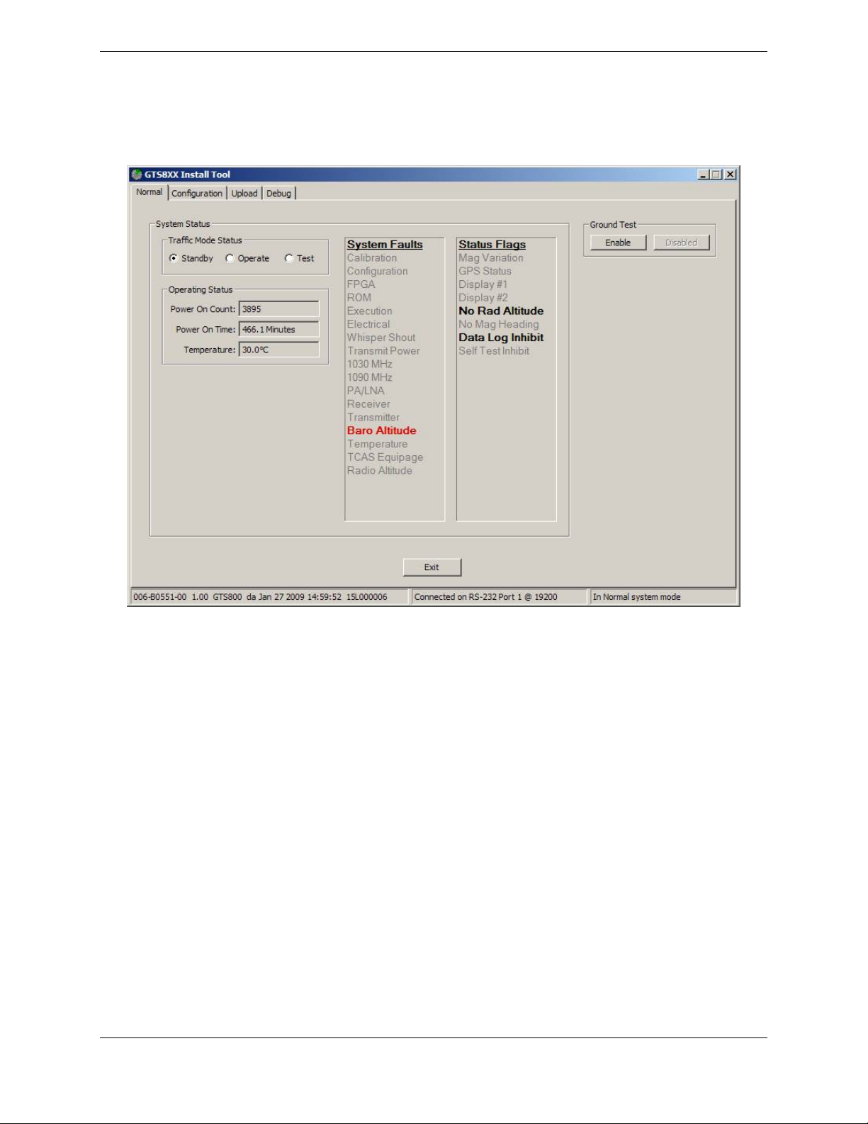
3.5.2.1 Normal System Mode Tab
The Normal tab displays various faults, flags, and operational information. When the Normal tab is
selected, the unit is commanded to Normal System Mode.
Normal Mode –
System Faults:
Status Flags:
Traffic Mode Status:
Ground Test:
Figure 3-3. GTS 8XX Install Tool – Normal Tab
Red Bold text indicates that a fault is active.
Gray text indicates that there is no active fault.
(System Faults are described in the Self-Test section.)
Black Bold text indicates that a flag is set.
Gray text indicates that the flag is not set.
(Status Flags are described in the Self-Test section.)
Standby – Unit is not transmitting or receiving data
Operate – Unit is interrogating and processing received data
Test – Allows special transmit interrogation rates and data patterns to be initiated
(Selected mode is active.)
Enabled
Disabled
(Ground Test is described in the Ramp Test and Return to Service Tests section.
GTS 8XX/GPA 65 Installation Manual Page 3-7
190-00587-00 Revision 4TP
Page 42
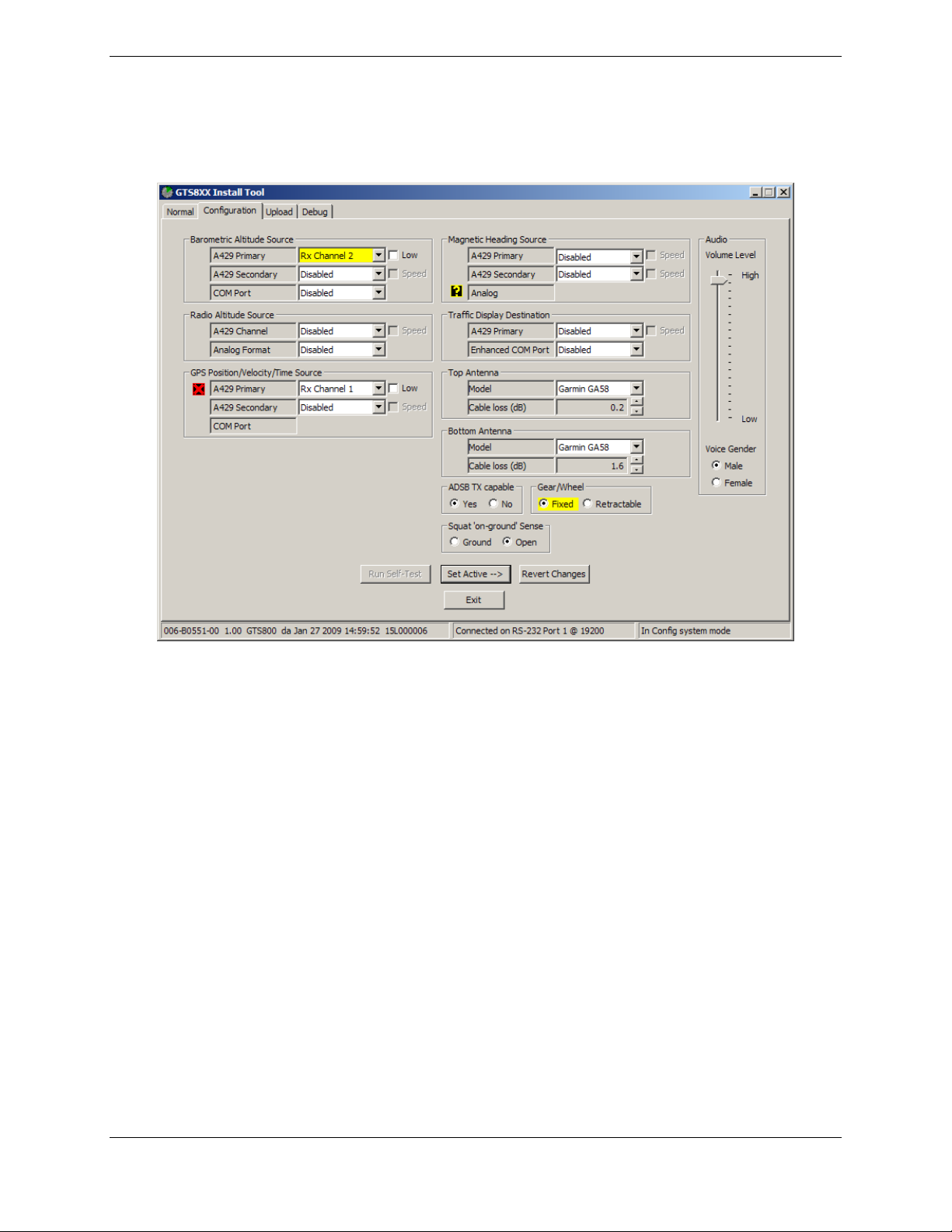
3.5.2.2 Configuration System Mode Tab
The Configuration tab displays configuration data and allows the installer to change the installation
configuration. When the Configuration tab is selected, the unit is commanded to Configuration System
Mode.
Figure 3-4. GTS 8XX Install Tool – Configuration Tab (GTS 800)
Page 3-8 GTS 8XX/GPA 65 Installation Manual
Revision 4TP 190-00587-00
Page 43
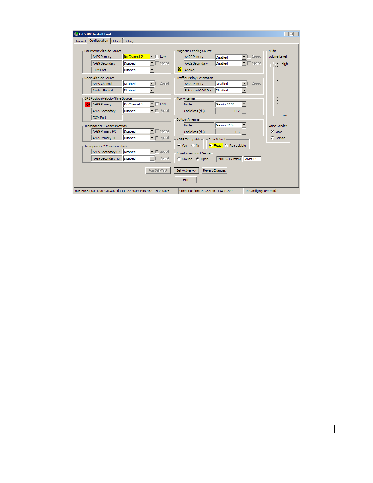
Figure 3-5. GTS 8XX Install Tool – Configuration Tab (GTS 820 and GTS 850)
The Configuration tab displays installation configuration options. Changes made in the Configuration tab
are not immediately committed to the GTS. Changed options will be colored yellow until ‘Set Active’ is
selected.
Configuration Mode –
Barometric Altitude Source:
Note: At least one source must be selected (same altitude source used for the
transponder).
Primary A429 RX Channels 1 - 6 or Disabled
Secondary A429 RX Channels 1 - 6 or Disabled
COM RS-232 Ports 1 - 5 or Disabled
Magnetic Heading Source (optional):
Primary A429 RX Channels 1 - 6 or Disabled
Secondary A429 RX Channels 1 - 6 or Disabled
Radio Altitude Source (optional):
A429 A429 RX Channels 1 - 6 or Disabled
Analog Disabled
ARINC 552
ARINC 552A
Bonzer MK10X
Collins ALT50
Collins ALT55
King KRA10
King KRA405
Sperry AA100
Terra TRA3000
Terra TRA3500
GTS 8XX/GPA 65 Installation Manual Page 3-9
190-00587-00 Revision 4TP
Page 44
GPS Position/Velocity/Time Source:
Note: At least one source required for ADS-B IN functionality.
Primary A429 RX Channels 1 - 6 or Disabled
Secondary A429 RX Channels 1 - 6 or Disabled
Traffic Display Destination:
Note: At least one source is required.
Primary A429 TX Channels 1 - 6 or Disabled
COM RS-232 Ports 1 - 5 or Disabled
Transponder 1 & 2 Communication:
Note: At least Transponder 1 RX and TX required for GTS 820 and GTS 850.
Primary should be configured for channels wired to Transponder 1.
Secondary should be configured for channels wired to Transponder 2 in a dual
transponder installation.
Primary RX A429 RX Channels 1 - 6 or Disabled
Primary TX A429 TX Channels 1 - 6 or Disabled
Secondary RX A429 RX Channels 1 - 6 or Disabled
Secondary TX A429 TX Channels 1 - 6 or Disabled
Top Antenna:
Model None
Monopole
Garmin GA58
Sensor Systems
Cable loss (dB) 0.2 – 4.0
Note: Cable loss information is described in Fabrication of
Coaxial Cable Assemblies section.
Bottom Antenna:
Model None
Monopole
Garmin GA58
Sensor Systems
Cable loss (dB) 0.2 – 4.0
Note: Cable loss information is described in Fabrication of
Coaxial Cable Assemblies section.
Note: All A429 options have the ability to select High or Low speed.
Note: If an input is inactive, a
If an input is active, a
If an input is in an unknown state, a
will be displayed.
will be displayed.
will be displayed.
Page 3-10 GTS 8XX/GPA 65 Installation Manual
Revision 4TP 190-00587-00
Page 45

Volume Level:
Allows audio volume level selection from 0 to -63 dB in 0.5 dB increments.
Maximum audio output is at least 80 mW into a 600 Ohm load. (6.93 Vrms)
Voice Gender:
Enter voice preference selection.
Gear/Wheel:
Enter type of aircraft gear design.
ADSB TX Capable:
Indicate whether aircraft is equipped with ADS-B transmitter.
Squat ‘on-ground’ Sense:
Indicate type of sense switch.
Mode S ID (HEX):
Applicable to GTS 820 and GTS 850 only. Enter Mode S transponder ID (must match the
Mode S ID used by the transponder).
Set Active:
Must select Set Active to enable the settings on the GTS 8XX.
Revert Changes:
Select to show current GTS 8XX settings.
An incorrect configuration will be reverted back to previous settings.
Note: Default is “disabled” for all inputs and outputs.
GTS 8XX/GPA 65 Installation Manual Page 3-11
190-00587-00 Revision 4TP
Page 46
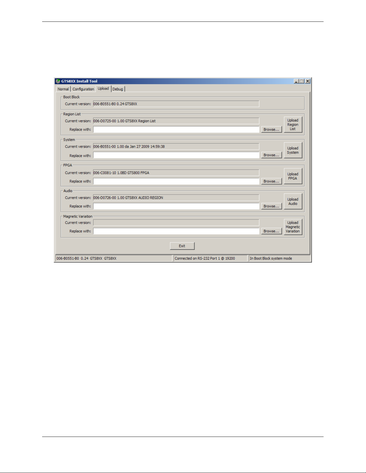
3.5.2.3 Upload System Mode Tab
The Upload tab displays version information for Boot Block, Region List, System, FPGA, Audio,
Magnetic Variation. Boot Block updating is not allowed. For other files, select the appropriate image
files and select upload.
Figure 3-6. GTS 8XX Install Tool – Upload Tab
3.5.2.4 Debug Tab
The Debug tab is reserved and not available for field installation use.
Page 3-12 GTS 8XX/GPA 65 Installation Manual
Revision 4TP 190-00587-00
Page 47

3.5.3 CDTI Display Setup and Configuration
For configuration of the displays, refer to their respective installation manuals.
• 500 Series Installation Manual (190-00181-02)
• GMX 200 Installation Manual (190-00607-04)
• GDU 620 Installation Manual (190-00601-04)
• G1000 Line Maintenance and Configuration Manual (190-00303-04)
• G1000 System Maintenance Manual LJ/VLJ (190-00903-00)
3.5.4 Self Test
A self-test feature tests the (aural) alarm, atte mpts self calibration, and activates ea ch display element in a
pre-determined sequential pattern to allow visual verification that display outputs issued by the digital
processor can be correctly interpreted by the pilot.
NOTE
Self tests may be performed indoors but signal multi-path from building walls may be a
factor. If problems are experienced, self tests should be performed outside away from
buildings, and where local traffic is not a factor.
With the GTS 8XX powered up and Standby indicated on the CDTI, cycle the GTS 8XX to Self Test. The
self test feature of the GTS 8XX tests the following i nternal parameters as well as performs calibration of
various components in the GTS 8XX:
a) Calibration data fault – Stored factory calibration parameters are invalid. Return unit to Garmin
for service.
b) Configuration data fault – Stored system configuration parameters are invalid or Mode S address
is invalid (All 0’s or F’s ). Fault will persist until configuration is corrected. Attempt
configuration per the Configuration Section.
c) FPGA fault – Check of the FPGA image failed. Fault will persist until valid FPGA image is
loaded. If upload of FPGA image was recently attempted, retry the upload. Otherwise, return
unit to Garmin for service.
d) ROM fault – Internal non-volatile memory failure, or invalid data image detected. If upload of
audio image or IGRF magnetic field image was recently attempted, retry the upload. Otherwise
return unit to Garmin for service.
e) Execution fault – CPU execution fault has occurred. Cycle power and retry self test. If fault
persists, return unit to Garmin for service.
f) Electrical fault – One of the internal electrical voltages are out of range. Fault will persist until
power is cycled. Check aircraft power supply. If fault persists, return unit to Garmin for service.
g) Whisper Shout fault – Transmitted power is out of tolerance. Check cable loss configuration,
antenna installation and all cable connections and retry self test. If fault persists, return unit to
Garmin for service.
h) Transmit Power fault - One of the internal transmitter power source voltages are out of range.
Fault will persist until power is cycled. Check aircraft power supply. If fault persists, return unit
to Garmin for service.
i) 1030 MHz Frequency Source fault - Transmit Frequency synthesizer is not locked. Cycle power
and retry self test. If fault persists, return unit to Garmin for service.
j) 1090 MHz Frequency Source fault - Receive Frequency synthesizer is not locked. Cycle power
and retry self test. If fault persists, return unit to Garmin for service.
GTS 8XX/GPA 65 Installation Manual Page 3-13
190-00587-00 Revision 4TP
Page 48

k) Receiver Calibration fault. Check antenna installation and all cable connections and retry self
test. Ensure that self test occurs in area free of buildings and large objects that can reflect signals.
If fault persists, return unit to Garmin for service.
NOTE
Receiver self-calibration is performed prior to the transmitter self-calibration. In the
event that a receiver calibration fault occurs, a transmitter self-calibration will not be
performed.
l) Transmitter Calibration fault. Check antenna installation and all cable connections and retry self
test. Ensure that self test occurs in area free of buildings and large objects that can reflect signals.
If fault persists, return unit to Garmin for service.
NOTE
A transmitter self-calibration can only be performed after a successful receiver selfcalibration.
m) Barometric Altitude Input fault – Own ship barometric altitude calculation is invalid or has timed
out. Check wiring to source of barometric altitude and ensure that source is operating. Fault will
clear as soon as valid barometric altitude data is received.
n) Main Board Temperature fault – Main board temperature or RF receiver temperature is greater
than 90° Celsius or less than -60° Celsius. Fault will persist until internal temperature returns to
acceptable range.
o) TCAS Equipage Timeout fault – TCAS Equipage data is not being received or has timed out for
800ms. Check wiring to TCAS Equipage data source and ensure that source is operating. Fault
will clear as soon as valid TCAS Equipage data is received.
The self test feature also checks the following external parameters:
a) Mag Variation – Magnetic variation data (difference between ‘True’ North and Magnetic North)
is available.
b) GPS Status – GPS Position, Velocity and Time data is available
c) Display #1 status - Check of Traffic display #1 discrete input is inactive for 2 or more seconds.
d) Display #2 status - Check of Traffic display #2 discrete input is inactive for 2 or more seconds.
e) Radio Altimeter Input status – Radio altimeter is installed and radio altimeter input status is
inactive.
f) Magnetic Heading Input status – Invalid magnetic heading data is received.
g) Maintenance/Data logger Input status – Data logger is inhibited if active.
h) Self Test Inhibit status – Self test is inhibited if active.
Page 3-14 GTS 8XX/GPA 65 Installation Manual
Revision 4TP 190-00587-00
Page 49
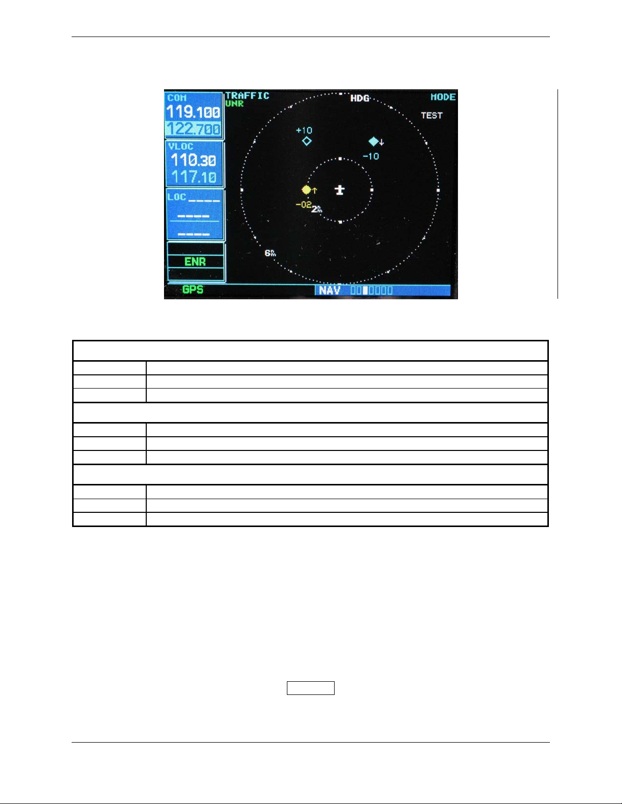
When the display receives an indication that a pilot initiated Self Test is in progress, this state is clearly
annunciated on the traffic display and the following test patterns will be executed.
Figure 3-7. Self Test
Table 3-5. Self Test
Intruder #1 (transmitted in intruder number field)
2.0 NM
Vertical Rate = Climbing, relative altitude = –200 feet
TA, Bearing = –90 degrees
Intruder #2 (transmitted in intruder number field)
3.625 NM
Vertical Rate = Descending, relative altitude = –1,000 feet
Prox Traffic, Bearing = +33.75 degrees
Intruder #3 (transmitted in intruder number field)
3.625 NM
No vertical rate, relative altitude = +1,000 feet
Other traffic, bearing = –33.75 degrees.
Audio annunciation shall be:
GTS 800/820 - “TAS system Passed” or “TAS system Failed”
GTS 850 - “TCAS system Passed” or “TCAS system Failed”
Any faults and flags are also displayed on the Normal tab of the GTS8XX Install Tool.
Faults that occur will be colored in red and flags will be colored in black.
If self test fails, refer to the diagnostics data to determine a cause.
Insure that no Intruder appears at close range to own aircraft.
NOTE
If the intruder appears at close range to own aircraft, verify that the mutual suppression
line is connected between GTS 8XX and other L-band equipment (transponder, DME,
etc.).
GTS 8XX/GPA 65 Installation Manual Page 3-15
190-00587-00 Revision 4TP
Page 50
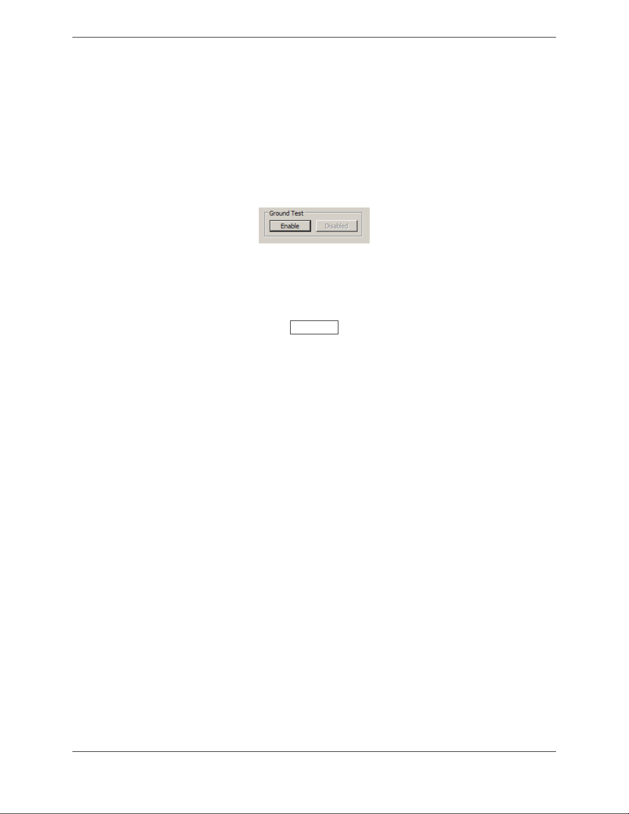
3.5.5 Ramp Test and Return To Service Test
Using a ramp tester, such as a TIC TR220 or equivalent, make the following setup and measurements to
verify GTS 8XX operational and surveillance functional.
To select a scenario that will properly converge and intercept the GTS 8XX, the GTS 8XX must be in
Ground Test mode. To enable Ground Test mode, the aircraft must be on the ground and the GTS 8XX
must be in Normal System mode and in Standby.
Activate ground test mode by clicking ‘Enable’ in the Ground Test field on the Normal tab of the GTS
8XX Install Tool.
Figure 3-8. Ground Test
This simulates the GTS to be airborne at 50,000 ft with magnetic heading of 0°.
NOTE
The GTS 8XX will not accept the Ground Test command unless the unit is in Standby and
the squat switch indicates the aircraft is on the ground.
Position the test set directional antenna with a clear line of sight to the GTS 8XX antenna at 90 degrees.
With the GTS 8XX powered up and in Standby mode indicated on the CDTI, cycle the GTS 800 to
“Operate”.
Select the following scenario:
Set the intruder type as ATCRBS.
Intruder Start Distance Intruder Start Altitude Vertical Speed Velocity
10 NM 50,000 ft 0 fpm. 360 Kts
Initiate the intruder scenario and observe the following:
• Traffic should be acquired at approximately 10 NM at 90 degree bearing and co-altitude.
Observe intruder closes on own aircraft at a rate of .1 NM/sec.
• The intruder should transition from Other Traffic (displayed as an open diamond with 00
displayed above), to proximate traffic (displayed as a filled white diamond with 00
displayed above), to a Traffic Advisory (TA) alarm.
• The appropriate TA symbology (yellow filled circle with 00 displayed above, and an audio
annunciation of "Traffic! 3 O'clock! At Altitude! 3 Miles!"), displayed when the
intruder approaches within 3 NM.
Page 3-16 GTS 8XX/GPA 65 Installation Manual
Revision 4TP 190-00587-00
Page 51

3.5.6 Antenna Verification
The first step in antenna verification is to verify auto-calibration operates without indicating a fault.
1. With the GTS 8XX powered up and “Standby” indicated on the CDTI cycle the GTS 8XX to
“Operate”. Each time the GTS 8XX transitions between these modes a self test of the antenna
circuit is initialized. If the antenna connection is not correct the CDTI will display “Failure”
indicating it will be necessary to recheck the antenna coaxial connections. If the CDTI
displays “Operate” without indicating a fault, proceed to the next step of antenna verification.
Using a ramp tester, such as a TIC TR220 or equivalent, make the following set up and measurements to
assure the antenna is properly connected and the GTS 8XX is operational.
2. Position the test set directional antenna with a clear line of sight to the GTS8XX antenna.
3. Ensure that the transmitter or receiver (RX/TX) that you are testing is significantly closer to the
ramp tester than another operating RX/TX, or erroneous and inaccurate results may occur. All
four quadrants (forward, starboard, aft, and port) will be similarly tested to verify bearing of
simulated intruder supplied via the ramp tester are correctly displayed on the CDTI.
4. Using the ramp tester, select the proper antenna gain and distance to aircraft.
5. Position ramp test set at 0 degrees.
6. Turn the test set on.
7. Connect the directional antenna to the ramp test set.
8. Set the multifunction test set to perform “TCAS” testing. Configure the GTS 8XX to the
normal operating mode.
9. Program a static intruder per the following scenario:
NOTE
See ramp test set operators manual to set the following parameters
Intruder Start Distance Intruder Start Altitude Vertical Speed Velocity
2 NM 50,000 0 fpm. 0 Kts
10. Set the intruder type as ATCRBS.
11. Verify a target is annunciated on the GTS 8XX TAS/TCAS display at the correct bearing of
approximately 0 degree azimuth at 2 NM and co-altitude (read as 00 above a filled diamond
indicating proximate traffic).
12. Toggle intruder traffic to standby or off.
13. Reposition ramp test set and directional antenna to a starboard position of 90 degrees.
GTS 8XX/GPA 65 Installation Manual Page 3-17
190-00587-00 Revision 4TP
Page 52

14. Reengage the same intruder scenario as above.
15. Verify a target is annunciated on the GTS 8XX TAS/TCAS display at the correct bearing of
approximately 90 degree azimuth at 2 NM and co-altitude.
16. Toggle intruder traffic to standby or off.
17. Reposition ramp test set and directional antenna to an aft position of 180 degrees.
18. Reengage the same intruder scenario as above.
19. Verify a target is annunciated on the GTS 8XX TAS/TCAS display at the correct bearing of
approximately 180 degree azimuth at 2 NM and co-altitude.
20. Toggle intruder traffic to standby or off.
21. Reposition ramp test set and directional antenna to a port position of 270 degrees.
22. Reengage the same intruder scenario as above.
23. Verify a target is annunciated on the GTS 8XX TAS/TCAS display at the correct bearing of
approximately 270 degree azimuth at 2 NM and co-altitude.
24. Toggle intruder traffic to standby or off.
25. If the bearing is not as anticipated, recheck the antenna coaxial connections and verify the
correct antenna type is selected.
NOTE
If multiple targets are displayed during the antenna tests, recheck the antenna coaxial
connections.
Page 3-18 GTS 8XX/GPA 65 Installation Manual
Revision 4TP 190-00587-00
Page 53

3.6 GA 58 Antenna Installation
Refer to the GA 58 installation drawing shown in Appendix A of this manual.
CAUTION
Do not use construction grade RTV sealant or sealants containing acetic acid. These
sealants may damage the electrical connections to the antenna. Use of these type sealants
may void the antenna warranty.
1. Refer to the GA 58 installation drawing shown in Appendix A for the mounting cutout.
2. For composite aircraft, fabricate a ground plane under the antenna base plate on the internal
surface of the aircraft with recommended minimum dimensions of 18” x 18”, with center of
ground plane under the center of the antenna baseplate. Refer to notes in Antenna
Considerations section and Electrical Bonding section of this document.
3. For metal skin aircraft, do NOT remove paint on outer skin of aircraft under the footprint of the
antenna baseplate. The painted surface prevents corrosion.
4. Install a doubler plate to reinforce the aircraft skin as necessary.
5. Place the supplied O-ring, 251-00011-00, in the groove on the bottom surface of the antenna.
6. Mount the antenna to the airframe with the four supplied #8-32 stainless steel screws, 211-
60209-16. Washers and locking nuts (not provided, may be part of doubler plate) are required
to secure the antenna. Apply torque evenly across all mounting screws.
7. Ensure that the antenna base and aircraft skin are in continuous contact.
8. Fillet seal the antenna and gasket to the fuselage using a good quality electrical grade sealant,
MIL-S-8802B or equivalent. Run a bead of the sealant along the edge of the antenna where it
meets the exterior aircraft skin. Use caution to ensure that the antenna connector is not
contaminated with sealant. Seal the mounting screws with sealant.
9. Connect the four antenna cables ensuring each cable is connected to the correct antenna
connector. Each antenna connector and cable has a matching color band.
GTS 8XX/GPA 65 Installation Manual Page 3-19
190-00587-00 Revision 4TP
Page 54

3.7 GPA 65 PA/LNA Installation
Refer to the GPA 65 installation drawing shown in Appendix A of this manual.
1. Assemble the wiring harness and circular connector per Section 3.4.
2. Assemble the coaxial cables per Section 2.4.1.
3. Mount the unit to a suitable mounting location using #8-32 pan head screws (4 ea)
(not provided).
4. Connect the circular connector and eight coaxial cables ensuring each coaxial cable is
connected to the correct jack connector. Each jack connector and cable has a matching color
band.
3.8 Continued Airworthiness
Maintenance of the GTS 8XX and GPA 65 is “on condition” only.
Page 3-20 GTS 8XX/GPA 65 Installation Manual
Revision 4TP 190-00587-00
Page 55

4 SYSTEM INTERCONNECTS
4.1 GTS 8XX Pin Function List
4.1.1 P8001 (Digital)
View of J8001 connector from back of unit
60 61 62 63 64 65 66 67 68 69 70 71 72 73 74 75 76 77 78
40
21 22 23 24 25 26 27
1 2 3 4 5 6 7 8 9 10 11121314151617181920
Pin Pin Name I/O
1 CONFIG MODULE GROUND -2 RS-232 OUT 1 Out
3 RS-232 IN 1 In
4 SIGNAL GROUND -5 RS-232 OUT 2 Out
6 RS-232 IN 2 In
7 SIGNAL GROUND -8 RS-232 OUT 3 Out
9 RS-232 IN 3 In
10 SIGNAL GROUND -11 RS-232 OUT 4 Out
12 RS-232 IN 4 In
13 SIGNAL GROUND -14 ARINC 429 OUT 1 A Out
15 ARINC 429 OUT 1 B Out
16 ARINC 429 IN 1 A In
17 ARINC 429 IN 1 B In
18 SIGNAL GROUND -19 GPS PPS 1 IN In
20 SIGNAL GROUND -21 CONFIG MODULE POWER OUT Out
22 SIGNAL GROUND -23 ARINC 429 OUT 2 A Out
24 ARINC 429 OUT 2 B Out
25 ARINC 429 IN 2 A In
26 ARINC 429 IN 2 B In
27 SIGNAL GROUND -28 ARINC 429 OUT 3 A Out
29 ARINC 429 OUT 3 B Out
30 ARINC 429 IN 3 A In
31 ARINC 429 IN 3 B In
32 SIGNAL GROUND -33 ARINC 429 OUT 4 A Out
34 ARINC 429 OUT 4 B Out
35 ARINC 429 IN 4 A In
36 ARINC 429 IN 4 B In
37 RS-422 IN A In
38 RS-422 IN B In
43 44 45 46 47 48 49 50 51 52 53 54 55 565758 59
41 42
30 31 32 33 34 35 36 37 38 39
28 29
GTS 8XX/GPA 65 Installation Manual Page 4-1
190-00587-00 Revision 4TP
Page 56

Connector P8001, continued
Pin Pin Name I/O
39 SIGNAL GROUND -40 CONFIG MODULE DATA I/O
41 SIGNAL GROUND -42 ARINC 429 OUT 5 A Out
43 ARINC 429 OUT 5 B Out
44 ARINC 429 IN 5 A In
45 ARINC 429 IN 5 B In
46 SIGNAL GROUND -47 ARINC 429 OUT 6 A Out
48 ARINC 429 OUT 6 B Out
49 ARINC 429 IN 6 A In
50 ARINC 429 IN 6 B In
51 SIGNAL GROUND -52 ETHERNET OUT A Out
53 ETHERNET OUT B Out
54 ETHERNET IN A Out
55 ETHERNET IN B Out
56 SIGNAL GROUND -57 RS-422 OUT A Out
58 RS-422 OUT B Out
59 SIGNAL GROUND -60 CONFIG MODULE CLOCK Out
61 TOP PA/LNA DATA RS-422 OUT A Out
62 TOP PA/LNA DATA RS-422 OUT B Out
63 TOP PA/LNA DATA RS-422 IN A In
64 TOP PA/LNA DATA RS-422 IN B In
65 RESERVED -66 RESERVED -67 RESERVED -68 RESERVED -69 SPARE -70 SPARE -71 SPARE -72 SPARE -73 GPS PPS IN 2 HI In
74 GPS PPS IN 2 LO In
75 USB VBUS POWER In
76 USB DATA HI I/O
77 USB DATA LO I/O
78 USB GROUND --
Page 4-2 GTS 8XX/GPA 65 Installation Manual
Revision 4TP 190-00587-00
Page 57

4.1.2 P8002 (Analog/Discrete)
View of J8002 connector from back of unit
60 61 62 63 64 65 66 67 68 69 70 71 72 73 74 75 76 77 78
40
21 22 23 24 25 26 27
1 2 3 4 5 6 7 8 9 10 11121314151617181920
Pin Pin Name I/O
1 SIGNAL GROUND --
2 RESERVED --
3 RESERVED --
4 RESERVED --
5 SIGNAL GROUND --
6 AIR/GROUND* In
7 SPARE --
8 TRAFFIC DISPLAY 1 STATUS VALID* In
9 TRAFFIC DISPLAY 2 STATUS VALID* In
10 GEAR DOWN AND LOCKED* In
11 TA INHIBIT* 1 In
12 TA INHIBIT* 2 In
13 RESERVED -14 SELF TEST INHIBIT PROGRAM* In
15 TA INTRUDER DISPLAY LIMIT 16 PROGRAM * In
16 TA INTRUDER DISPLAY LIMIT 8 PROGRAM * In
17 TA INTRUDER DISPLAY LIMIT 4 PROGRAM * In
18 TA INTRUDER DISPLAY LIMIT 2 PROGRAM * In
19 TA INTRUDER DISPLAY LIMIT 1 PROGRAM * In
20 RESERVED -21 SIGNAL GROUND -22 RESERVED -23 RESERVED -24 RESERVED -25 RESERVED -26 RESERVED -27 RESERVED -28 RESERVED -29 RESERVED -30 RESERVED -31 RESERVED -32 RESERVED -33 RESERVED -34 RESERVED -35 RESERVED -36 RESERVED -37 RESERVED -38 RESERVED -39 SIGNAL GROUND -40 SIGNAL GROUND -41 HEADING X HI In
43 44 45 46 47 48 49 50 51 52 53 54 55 565758 59
41 42
30 31 32 33 34 35 36 37 38 39
28 29
GTS 8XX/GPA 65 Installation Manual Page 4-3
190-00587-00 Revision 4TP
Page 58

Connector P8002, continued
Pin Pin Name I/O
42 HEADING X LO (GROUND) -43 SIGNAL GROUND -44 HEADING Y HI In
45 HEADING Y LO (GROUND) -46 SIGNAL GROUND -47 SPARE -48 EXTERNAL SUPPRESSION I/O I/O
49 SIGNAL GROUND -50 TA DISPLAY ENABLE* Out
51 AURAL TA ALERT* Out
52 SPARE -53 VISUAL TA ALERT* Out
54 TRAFFIC SYSTEM STATUS VALID* Out
55 RESERVED -56 RESERVED -57 SIGNAL GROUND -58 ALERT AUDIO OUT HI Out
59 ALERT AUDIO OUT LO Out
60 HEADING Z HI (GROUND) In
61 HEADING Z LO (GROUND) -62 SIGNAL GROUND -63 26 VAC HEADING REF HI In
64 26 VAC HEADING REF LO In
65 SIGNAL GROUND -66 SPARE -67 SPARE -68 HEADING VALID In
69 HEADING VALID* In
70 SIGNAL GROUND -71 ANALOG RADAR ALTIMETER HI In
72 ANALOG RADAR ALTIMETER LO In
73 SIGNAL GROUND -74 SELF TEST INITIALIZE SELECT* In
75 TRAFFIC OPERATE/STANDBY* In
76 ANALOG RADAR ALTIMETER VALID In
77 SPARE -78 SIGNAL GROUND --
An asterisk (*) following a signal name denotes that the signal is Active Low. Refer to Section 4.6.4 for
signal description.
Page 4-4 GTS 8XX/GPA 65 Installation Manual
Revision 4TP 190-00587-00
Page 59

4.1.3 P8003 (Power Supply)
View of J8003 connector from back of unit
1
20
4623
5
21
22 23 24 25 26 27 28 29 30 31 32 333435 36
8109
7
11 12
13 14
15
16 17
18
19
37
Pin Pin Name I/O
1 POWER GROUND --
2 AIRCRAFT POWER 1 In
3 AIRCRAFT POWER 1 In
4 AIRCRAFT POWER 2 In
5 AIRCRAFT POWER 2 In
6 POWER GROUND --
7 +6 VDC PA/LNA POWER OUT Out
8 +6 VDC PA/LNA POWER OUT Out
9 RESERVED -10 RESERVED -11 POWER GROUND -12 +35 VDC PA/LNA POWER OUT Out
13 +35 VDC PA/LNA POWER OUT Out
14 POWER GROUND -15 -5 VDC PA/LNA POWER OUT Out
16 -5 VDC PA/LNA POWER OUT Out
17 POWER GROUND -18 TRAFFIC SYSTEM REMOTE POWER ON* In
19 POWER GROUND -20 POWER GROUND -21 POWER GROUND -22 POWER GROUND -23 POWER GROUND -24 POWER GROUND -25 POWER GROUND -26 POWER GROUND -27 POWER GROUND -28 POWER GROUND -29 POWER GROUND -30 POWER GROUND -31 POWER GROUND -32 POWER GROUND -33 POWER GROUND -34 POWER GROUND -35 POWER GROUND -36 TRAFFIC SYSTEM REMOTE POWER OFF In
37 POWER GROUND --
An asterisk (*) following a signal name denotes that the signal is Active Low. Refer to Section 4.6.4 for
signal description.
GTS 8XX/GPA 65 Installation Manual Page 4-5
190-00587-00 Revision 4TP
Page 60

4.2 GPA 65 Pin Function List
4.2.1 P651
View of J651 connector from back of unit
Pin Pin Name I/O
A POWER GROUND --
B +35 VDC POWER IN In
C POWER GROUND --
D RESERVED --
E -5 VDC POWER IN In
F PA/LNA DATA RS-422 OUT B Out
G PA/LNA DATA RS-422 OUT A Out
H PA/LNA DATA RS-422 IN B In
J PA/LNA DATA RS-422 IN A In
K POWER GROUND --
L +6 VDC POWER IN In
M +35 VDC POWER IN In
N RESERVED -P +6 VDC POWER IN In
R RESERVED -S -5 VDC POWER IN In
T RESERVED --
U RESERVED -V RESERVED --
Page 4-6 GTS 8XX/GPA 65 Installation Manual
Revision 4TP 190-00587-00
Page 61
4.3 Power
4.3.1 Aircraft Power Functions
This section covers the power input requirements.
4.3.1.1 Aircraft Power
Pin Name Connector Pin I/O
AIRCRAFT POWER 1 P8003 2 In
AIRCRAFT POWER 1 P8003 3 In
AIRCRAFT POWER 2 P8003 4 In
AIRCRAFT POWER 2 P8003 5 In
AIRCRAFT GROUND P8003 21 -AIRCRAFT GROUND P8003 22 -AIRCRAFT GROUND P8003 23 -AIRCRAFT GROUND P8003 24 --
Pins 2 and 3 are internally connected to form AIRCRAFT POWER 1. Pins 4 and 5 are internally
connected to form AIRCRAFT POWER 2. AIRCRAFT POWER 1 and AIRCRAFT POWER 2 are
“diode ORed” to provide aircraft power redundancy.
4.3.1.2 Remote Power
Pin Name Connector Pin I/O
TRAFFIC SYSTEM REMOTE POWER ON* P8003 18 In
TRAFFIC SYSTEM REMOTE POWER OFF P8003 36 In
An asterisk (*) following a signal name denotes that the signal is Active Low.
Used to remotely control power.
Remote Power ON*
ACTIVE: Vin < 3 VDC or grounded (Unit ON)
INACTIVE: Vin > 8 VDC or floating (Unit OFF)
Remote Power OFF
ACTIVE: Vin > 8 VDC (Unit OFF)
INACTIVE: Vin < 3 VDC or floating (Unit ON)
Active Low Remote Power On
(J8003 Pin 18)
State Level State Level
Inactive Vin > 8 VDC or Open Inactive Vin < 3VDC or Open OFF
Active Vin < 3VDC or Gnd Inactive Vin < 3VDC or Open ON
Inactive Vin > 8 VDC or Open Active Vin > 8 VDC OFF
Active Vin < 3VDC or Gnd Active Vin > 8 VDC OFF
Active High Remote Power Off
(J8003 Pin 36)
Expected Unit State
GTS 8XX/GPA 65 Installation Manual Page 4-7
190-00587-00 Revision 4TP
Page 62
4.3.1.3 PA/LNA
Pin Name Connector Pin I/O
+6 VDC PA/LNA POWER OUT P8003 7 Out
+6 VDC PA/LNA POWER OUT P8003 8 Out
+35 VDC PA/LNA POWER OUT P8003 12 Out
+35 VDC PA/LNA POWER OUT P8003 13 Out
-5 VDC PA/LNA POWER OUT P8003 15 Out
-5 VDC PA/LNA POWER OUT P8003 16 Out
+6 VDC POWER IN P651 L In
+6 VDC POWER IN P651 P In
+35 VDC POWER IN P651 B In
+35 VDC POWER IN P651 M In
-5 VDC POWER IN P651 E In
-5 VDC POWER IN P651 S In
Used to provide power to the GPA 65.
Page 4-8 GTS 8XX/GPA 65 Installation Manual
Revision 4TP 190-00587-00
Page 63
4.4 Serial Data
4.4.1 RS-232
Pin Name Connector Pin I/O
RS-232 OUT 1 P8001 2 Out
RS-232 IN 1 P8001 3 In
RS-232 OUT 2 P8001 5 Out
RS-232 IN 2 P8001 6 In
RS-232 OUT 3 P8001 8 Out
RS-232 IN 3 P8001 9 In
RS-232 OUT 4 P8001 11 Out
RS-232 IN 4 P8001 12 In
The RS-232 outputs conform to EIA Standard RS-232C with an output voltage swing of at least ±5V
when driving a standard RS-232 load.
4.4.2 RS-422
Pin Name Connector Pin I/O
RS-422 IN A P8001 37 Out
RS-222 IN B P8001 38 In
RS-422 OUT A P8001 57 Out
RS-422 OUT B P8001 58 In
TOP PA/LNA DATA RS-422 OUT A P8001 61 Out
TOP PA/LNA DATA RS-422 OUT B P8001 62 Out
TOP PA/LNA DATA RS-422 IN A P8001 63 In
TOP PA/LNA DATA RS-422 IN B P8001 64 In
PA/LNA DATA RS-422 OUT B P651 F Out
PA/LNA DATA RS-422 OUT A P651 G Out
PA/LNA DATA RS-422 IN B P651 H In
PA/LNA DATA RS-422 IN A P651 J In
The RS-422 channels conform to EIA standard RS-422.
GTS 8XX/GPA 65 Installation Manual Page 4-9
190-00587-00 Revision 4TP
Page 64
4.4.3 ARINC 429
Pin Name Connector Pin I/O
ARINC 429 OUT 1 A P8001 14 Out
ARINC 429 OUT 1 B P8001 15 Out
ARINC 429 IN 1 A P8001 16 In
ARINC 429 IN 1 B P8001 17 In
ARINC 429 OUT 2 A P8001 23 Out
ARINC 429 OUT 2 B P8001 24 Out
ARINC 429 IN 2 A P8001 25 In
ARINC 429 IN 2 B P8001 26 In
ARINC 429 OUT 3 A P8001 28 Out
ARINC 429 OUT 3 B P8001 29 Out
ARINC 429 IN 3 A P8001 30 In
ARINC 429 IN 3 B P8001 31 In
ARINC 429 OUT 4 A P8001 33 Out
ARINC 429 OUT 4 B P8001 34 Out
ARINC 429 IN 4 A P8001 35 In
ARINC 429 IN 4 B P8001 36 In
ARINC 429 OUT 5 A P8001 42 Out
ARINC 429 OUT 5 B P8001 43 Out
ARINC 429 IN 5 A P8001 44 In
ARINC 429 IN 5 B P8001 45 In
ARINC 429 OUT 6 A P8001 47 Out
ARINC 429 OUT 6 B P8001 48 Out
ARINC 429 IN 6 A P8001 49 In
ARINC 429 IN 6 B P8001 50 In
The ARINC 429 outputs conform to ARINC 429 electrical specifications when loaded with up to 5
standard ARINC 429 receivers.
4.4.4 Ethernet
Pin Name Connector Pin I/O
ETHERNET OUT A P8001 52 Out
ETHERNET OUT B P8001 53 Out
EHTERNET IN A P8001 54 In
ETHERNET IN B P8001 55 In
This Ethernet based HSDB (High Speed Data Bus) meets the hardware aspects of IEEE standard 802.3
for 10 base T Ethernet communications.
Page 4-10 GTS 8XX/GPA 65 Installation Manual
Revision 4TP 190-00587-00
Page 65

4.4.5 USB
Pin Name Connector Pin I/O
USB VBUS POWER** P8001 75 In
USB DATA HI** P8001 76 I/O
USB DATA LO** P8001 77 I/O
USB GROUND P8001 78 --
**Signals have ESD (Electrostatic Discharge) protection, but not lightning protection. USB TYPE B
RECEPTACLE pigtail cable must be wired directly to P8001 to minimize lightning exposure.
This interface is used for unit configuration and software uploads. Conforms to the Universal Serial Bus
Version 1.1 standard for a “full-speed” device.
GTS 8XX/GPA 65 Installation Manual Page 4-11
190-00587-00 Revision 4TP
Page 66
4.5 Configuration
4.5.1 Configuration Module
Pin Name Connector Pin I/O
CONFIG MODULE GND P8001 1 -CONFIG MODULE PWR OUT** P8001 21 -CONFIG MODULE DATA** P8001 40 I/O
CONFIG MODULE CLK** P8001 60 I/O
**Signals have ESD (Electrostatic Discharge) protection, but not lightning protection.
4.6 Analog/Discrete
4.6.1 Heading Input
4.6.1.1 26 Volt AC References
Pin Name Connector Pin I/O
26 VAC HEADING REF HI P8002 63 In
26 VAC HEADING REF LO P8002 64 In
Used to sample AC inputs.
This signal must be the same phase and frequency as the indicator being driven.
Frequency: 400 Hz ± 10%
Voltage: 22.6 Vrms to 28.6 Vrms
Input Impedance:
>10 kΩ
4.6.1.2 Radar Altimeter
Pin Name Connector Pin I/O
ANALOG RADAR ALTIMETER HI P8002 71 In
ANALOG RADAR ALTIMETER LO P8002 72 In
Provides altitude information during approach.
Page 4-12 GTS 8XX/GPA 65 Installation Manual
Revision 4TP 190-00587-00
Page 67
4.6.2 Inputs From Gyros
Pin Name Connector Pin I/O
HEADING X P8002 41 In
HEADING LO (GROUND) P8002 42 -HEADING Y P8002 44 In
HEADING LO (GROUND) P8002 45 -HEADING Z (GROUND) P8002 60 In
HEADING LO (GROUND) P8002 61 --
Inputs heading information from a directional gyro.
3-wire synchro magnetic heading input, with HEADING Z grounded. Index reference is 0° as specified
by ARINC 407.
Frequency: 400Hz ± 10%
Voltage: 11.8 Vrms nominal, 13.0 Vrms maximum
Input Impedance:
Resolution: ± 0.1° or better
Accuracy: ± 2°
>10 kΩ
4.6.3 Audio
Pin Name Connector Pin I/O
ALERT AUDIO OUT HI P8002 58 Out
ALERT AUDIO OUT LO P8002 59 Out
4.6.4 Active Low Discrete Inputs
Pin Name Connector Pin I/O
AIR/GROUND* P8002 6 In
TRAFFIC DISPLAY 1 STATUS VALID* P8002 8 In
TRAFFIC DISPLAY 2 STATUS VALID* P8002 9 In
GEAR DOWN AND LOCKED* P8002 10 In
TA INHIBIT* 1 P8002 11 In
TA INHIBIT* 2 P8002 12 In
SELF TEST INHIBIT PROGRAM* P8002 14 In
TA INTRUDER DISPLAY LIMIT 16 PROGRAM * P8002 15 In
TA INTRUDER DISPLAY LIMIT 8 PROGRAM * P8002 16 In
TA INTRUDER DISPLAY LIMIT 4 PROGRAM * P8002 17 In
TA INTRUDER DISPLAY LIMIT 2 PROGRAM * P8002 18 In
TA INTRUDER DISPLAY LIMIT 1 PROGRAM * P8002 19 In
DATA RECORDER ENABLE* P8002 20 In
HEADING VALID* P8002 69 In
SELF TEST INITIALIZE SELECT* P8002 74 In
TRAFFIC OPERATE/STANDBY* P8002 75 In
An asterisk (*) following a signal name denotes that the signal is Active Low.
ACTIVE: 0 V ≤ Vin ≤ 3.5 V, or Rin ≤ 375 ohms
INACTIVE: 8 V ≤ Vin ≤ 36 V, or Rin ≥ 100k ohms
Source current is internally limited to approximately 1 mA max for a grounded input
GTS 8XX/GPA 65 Installation Manual Page 4-13
190-00587-00 Revision 4TP
Page 68
4.6.5 Active High Discrete Inputs
Pin Name Connector Pin I/O
HEADING VALID P8002 68 In
ANALOG RADAR ALTIMETER VALID P8002 76 In
ACTIVE: 8 V ≤ Vin ≤ 36 V
INACTIVE: 0 V ≤ Vin ≤ 3.5 V, or Rin ≥ 100k ohms
Sink current is internally limited to approximately 1 mA typical for an input connected to +28VDC.
4.6.6 Annunciator Output
Pin Name Connector Pin I/O
TA DISPLAY ENABLE* P8002 50 Out
AURAL TA ALERT* P8002 51 Out
VISUAL TA ALERT* P8002 53 Out
TRAFFIC SYSTEM STATUS VALID* P8002 54 Out
An asterisk (*) following a signal name denotes that the signal is Active Low.
ACTIVE: 0 V ≤ Vout ≤ 0.5 V or Rout ≤ 10 ohms, sinking up to 500 mA
INACTIVE: Rout ≥ 100k ohms to ground, withstanding up to +36 VDC.
4.7 Mutual Suppression Bus
Pin Name Connector Pin I/O
EXTERNAL SUPPRESSION I/O P8002 48 I/O
Mutual Suppression Input/Output bus compliant with ARINC 735A Attachment 8, with the exception that
the maximum applied DC steady state voltage is +30.3V. Suppression I/O signal is pulsed under normal
operation.
Page 4-14 GTS 8XX/GPA 65 Installation Manual
Revision 4TP 190-00587-00
Page 69
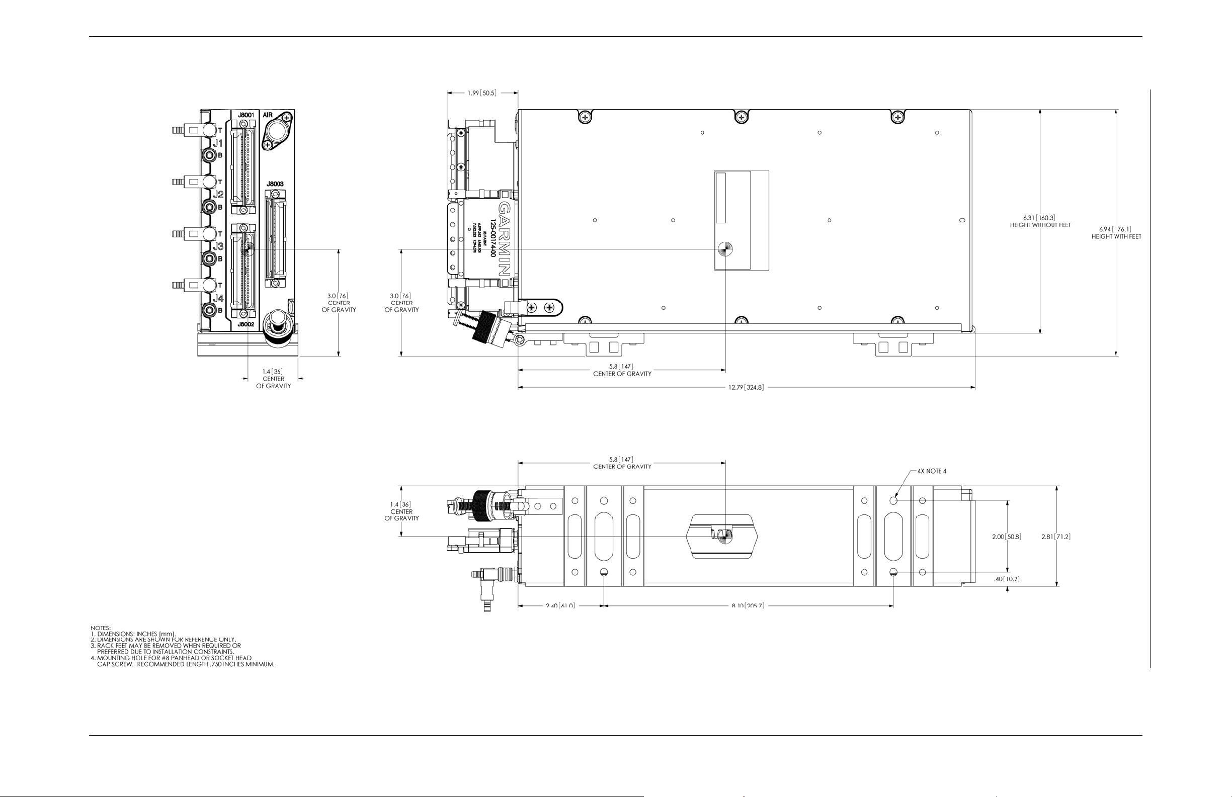
APPENDIX A OUTLINE & INSTALLATION DRAWINGS
Figure A-1. GTS 8XX Vertical Outline Drawing
GTS 8XX/GPA 65 Installation Manual Page A-1 (Page A-2 blank)
190-00587-00 Revision 4TP
Page 70
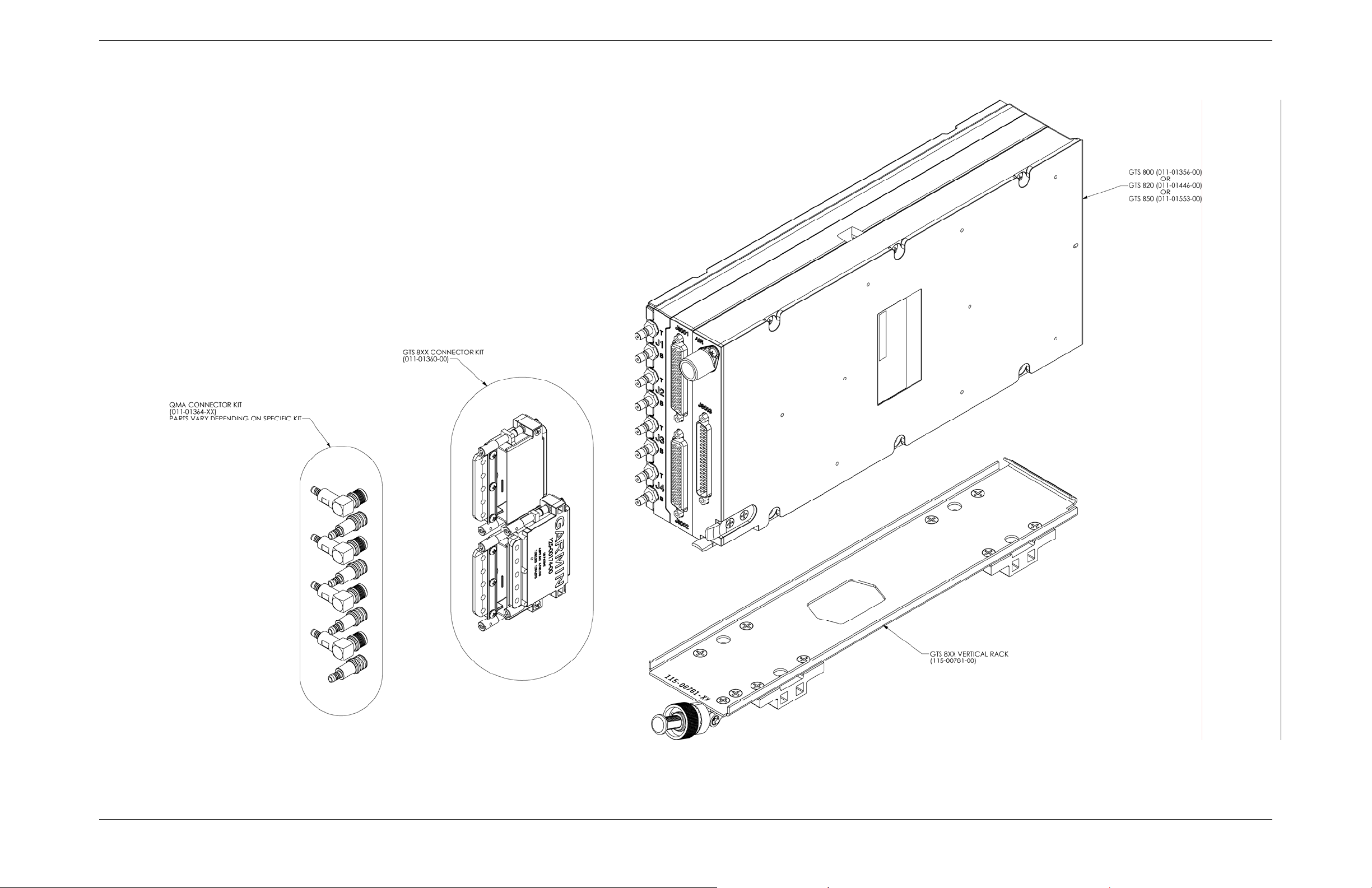
APPENDIX A OUTLINE & INSTALLATION DRAWINGS
Figure A-2. GTS 8XX Vertical Installation Drawing
GTS 8XX/GPA 65 Installation Manual Page A-3 (Page A-4 blank)
190-00587-00 Revision 4TP
Page 71
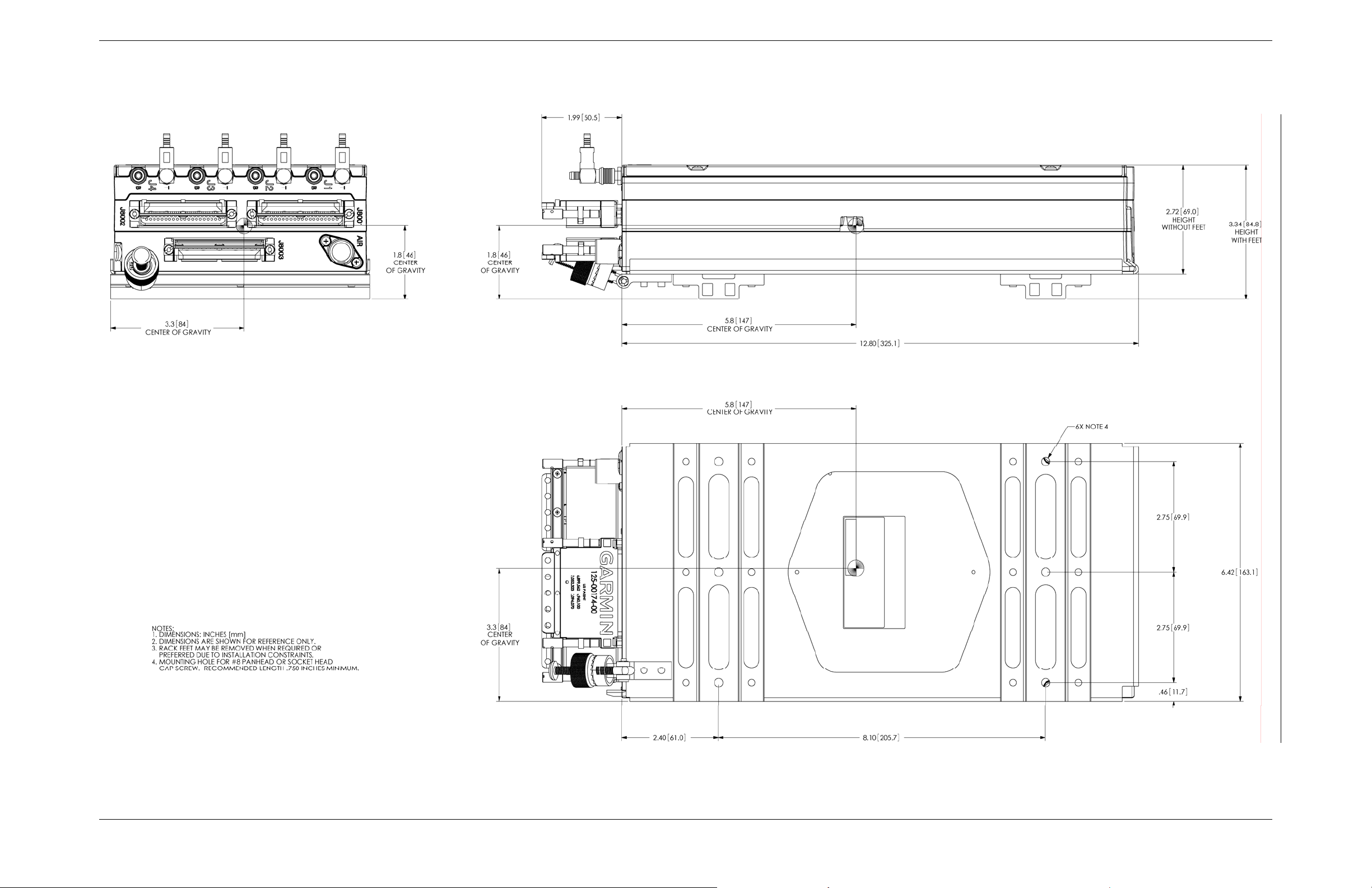
APPENDIX A OUTLINE & INSTALLATION DRAWINGS
Figure A-3. GTS 8XX Horizontal Outline Drawing
GTS 8XX/GPA 65 Installation Manual Page A-5 (Page A-6 blank)
190-00587-00 Revision 4TP
Page 72
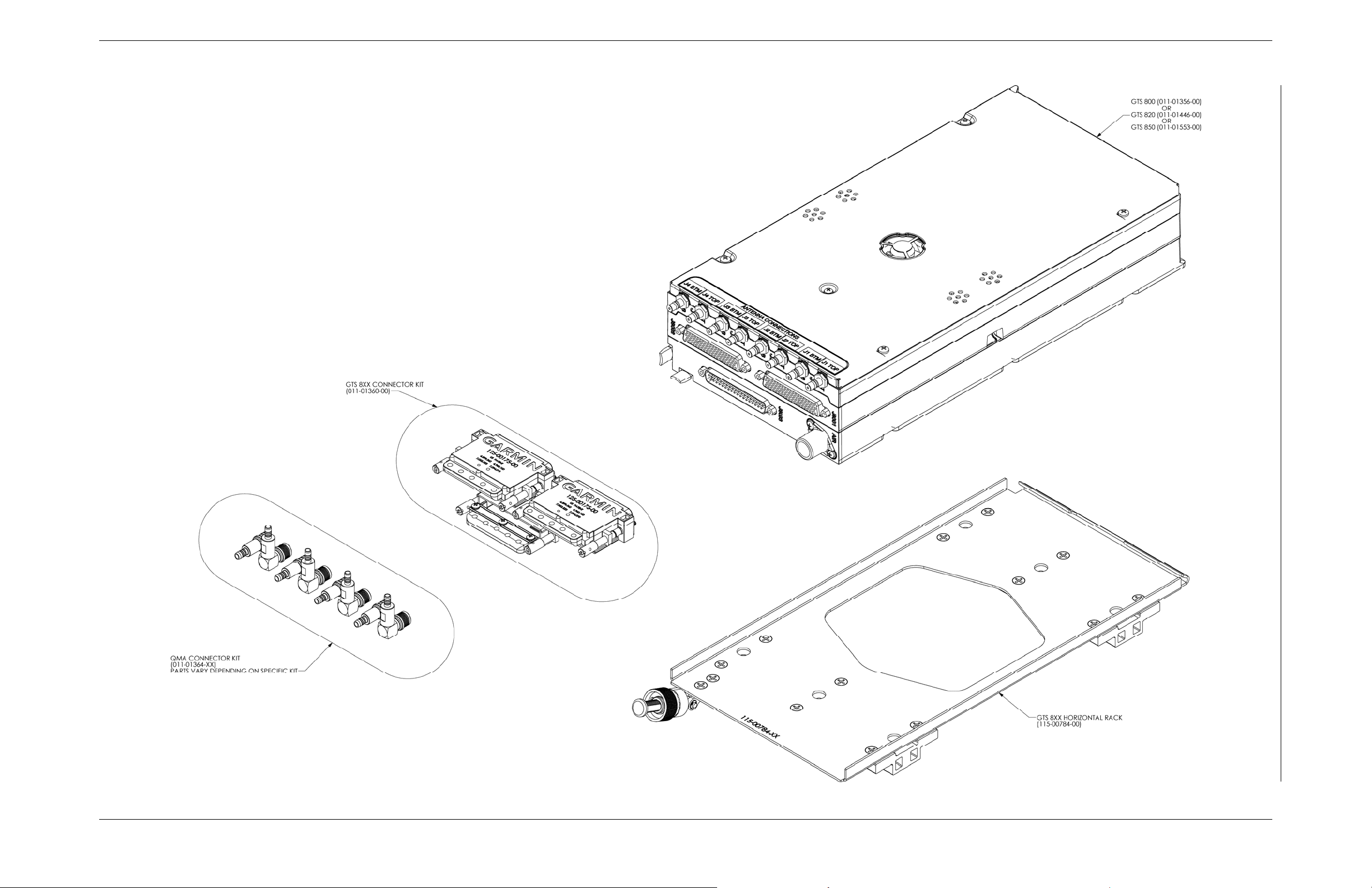
APPENDIX A OUTLINE & INSTALLATION DRAWINGS
Figure A-4. GTS 8XX Horizontal Installation Drawing
GTS 8XX/GPA 65 Installation Manual Page A-7 (Page A-8 blank)
190-00587-00 Revision 4TP
Page 73
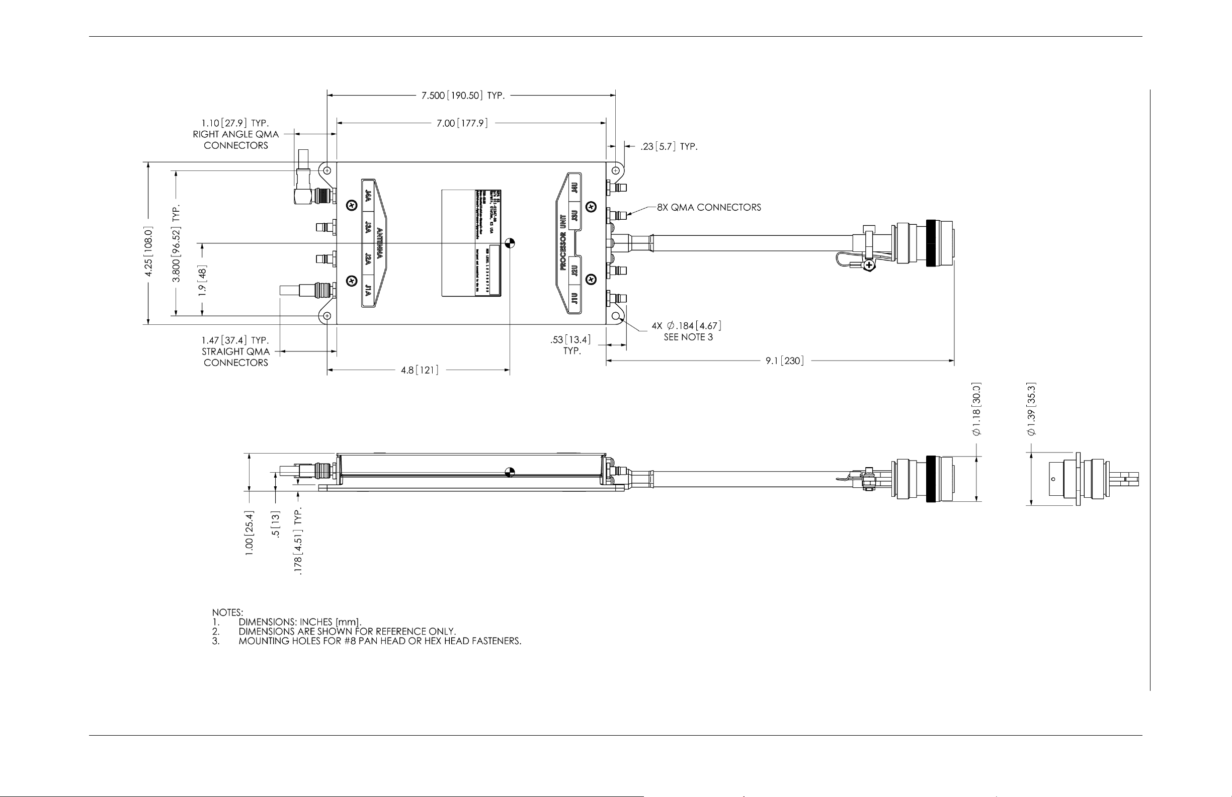
APPENDIX A OUTLINE & INSTALLATION DRAWINGS
Figure A-5. GPA 65 Outline Drawing
GTS 8XX/GPA 65 Installation Manual Page A-9 (Page A-10 blank)
190-00587-00 Revision 4TP
Page 74
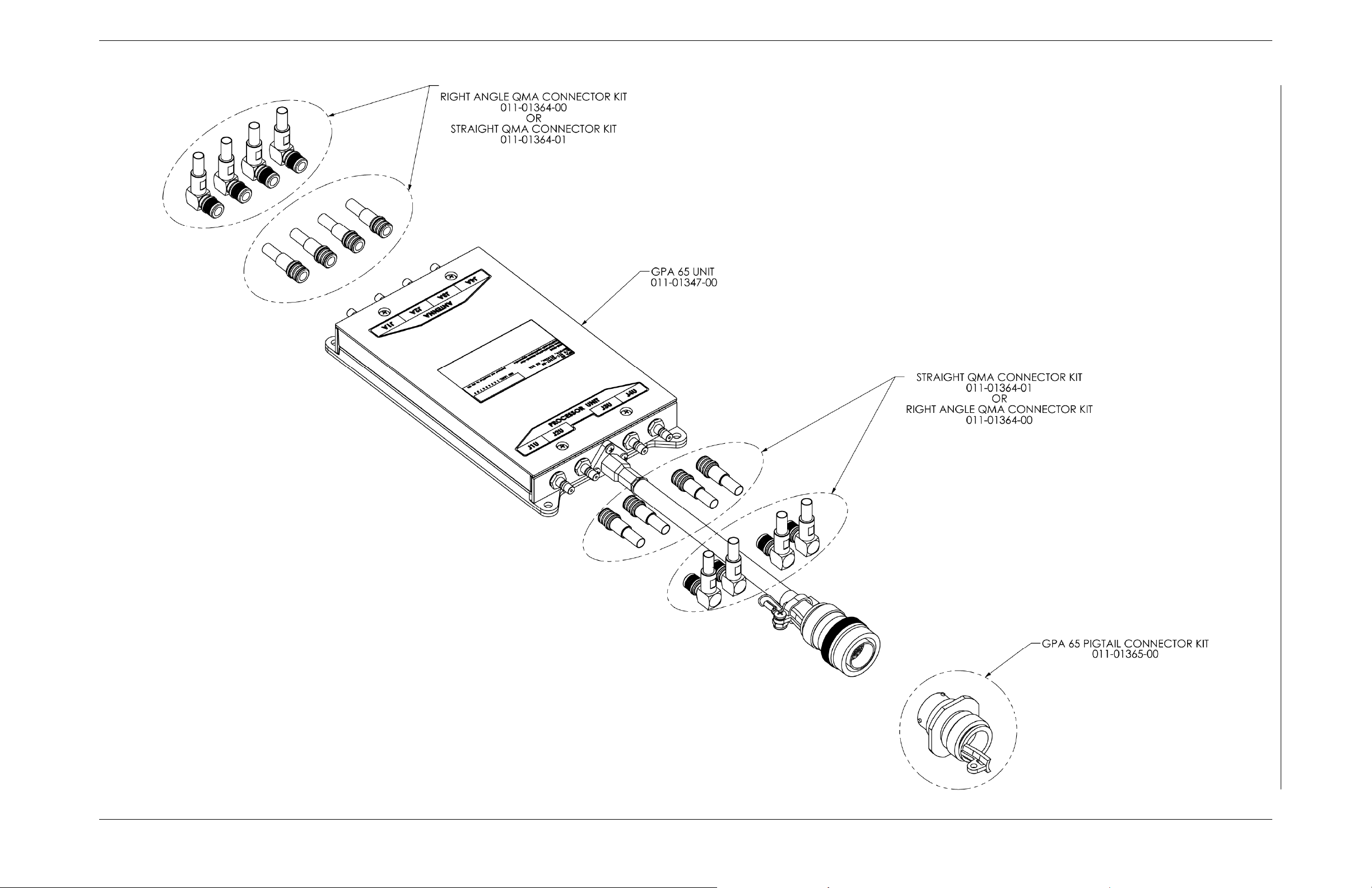
APPENDIX A OUTLINE & INSTALLATION DRAWINGS
Figure A-6. GPA 65 Installation Drawing
GTS 8XX/GPA 65 Installation Manual Page A-11 (Page A-12 blank)
190-00587-00 Revision 4TP
Page 75
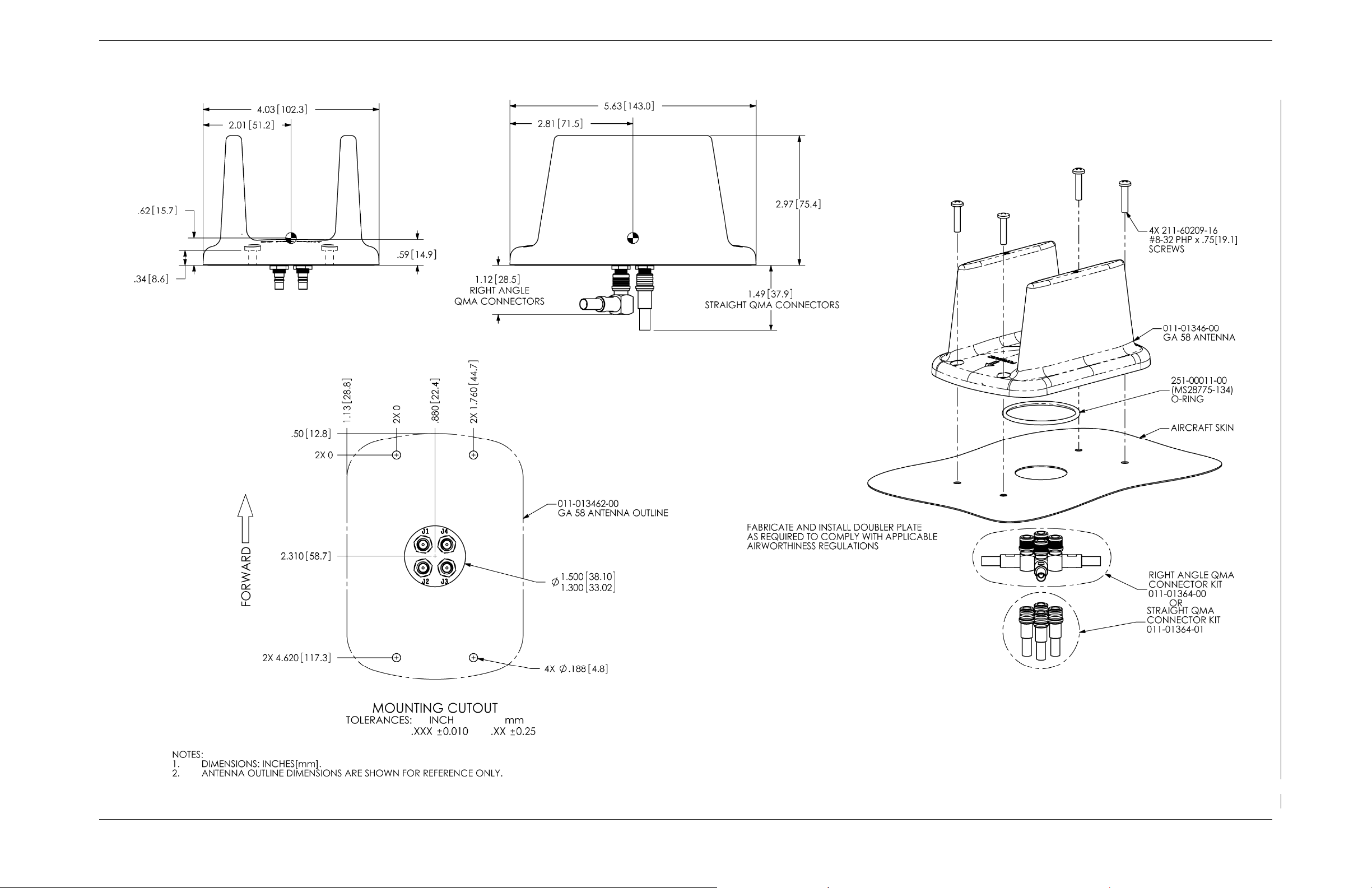
APPENDIX A OUTLINE & INSTALLATION DRAWINGS
Figure A-7. GA 58 Antenna Outline Drawing
GTS 8XX/GPA 65 Installation Manual Page A-13 (Page A-14 blank)
190-00587-00 Revision 4TP
Page 76
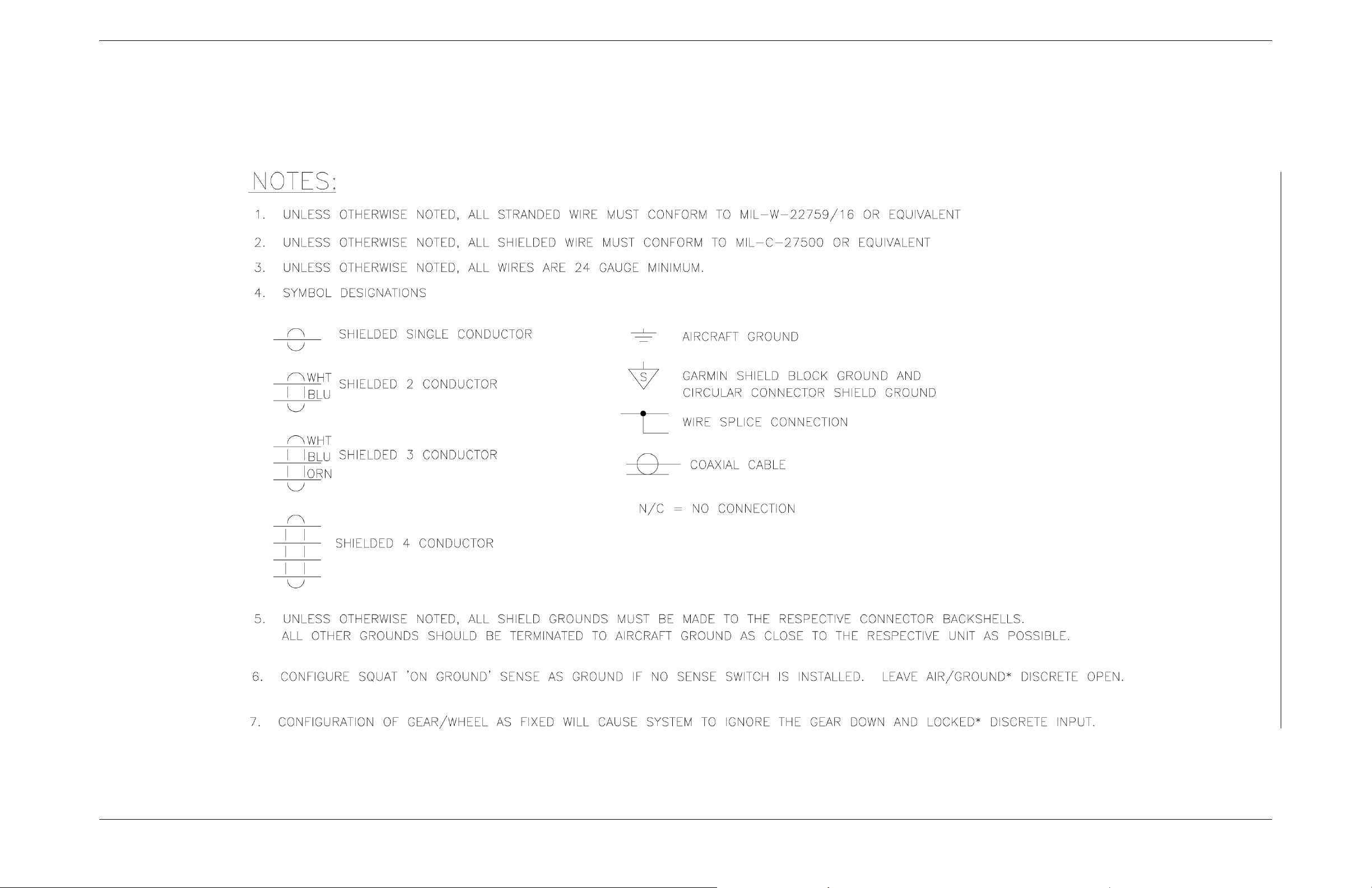
APPENDIX B INTERCONNECT EXAMPLE
Figure B-1. Notes
GTS 8XX/GPA 65 Installation Manual Page B-1 (Page B-2 blank)
190-00587-00 Revision 4TP
Page 77
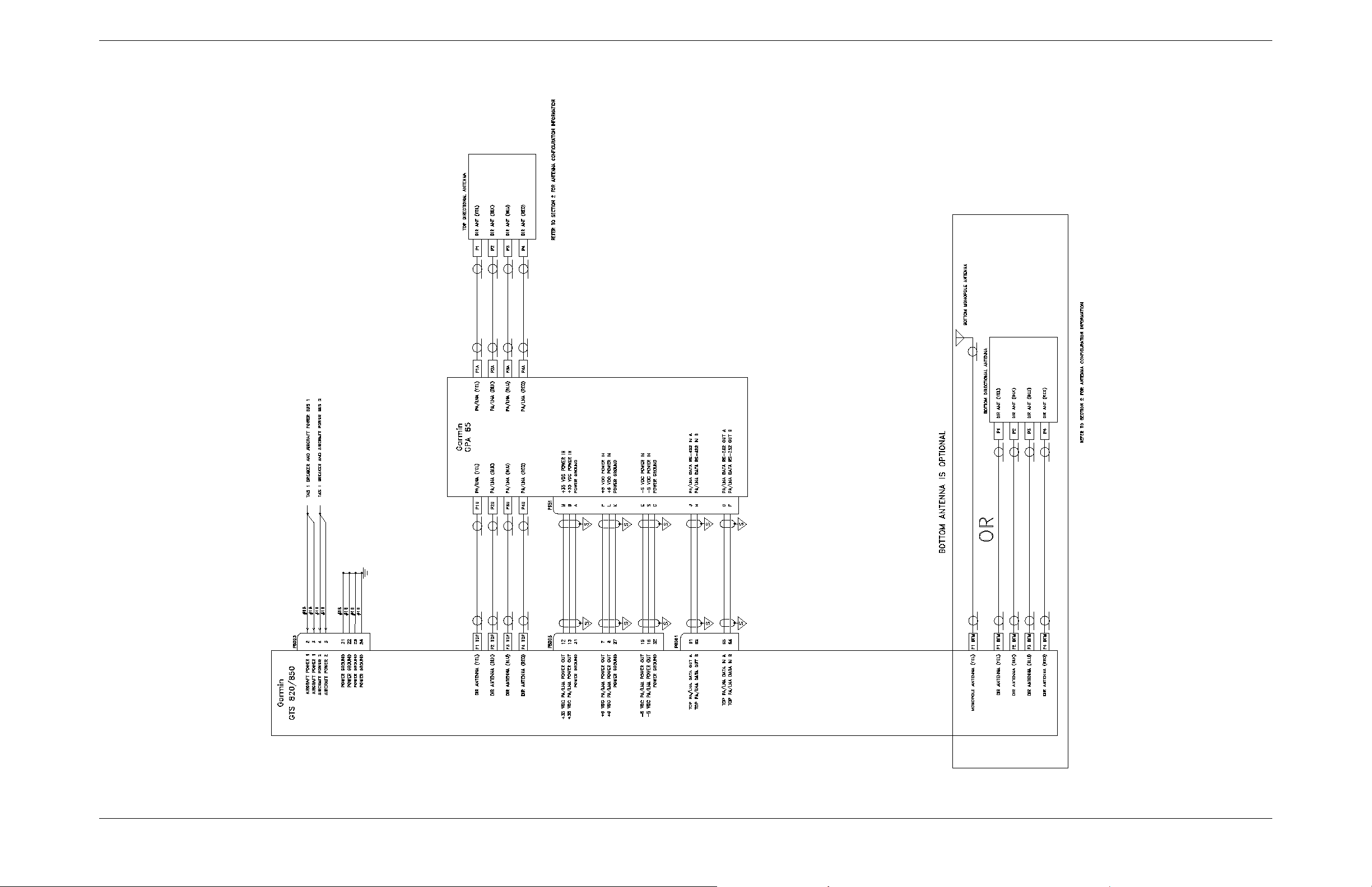
APPENDIX B INTERCONNECT EXAMPLE
Figure B-2. GTS 820/850/GPA 65 Example Interconnect
GTS 8XX/GPA 65 Installation Manual Page B-3 (Page B-4 blank)
190-00587-00 Revision 4TP
Page 78
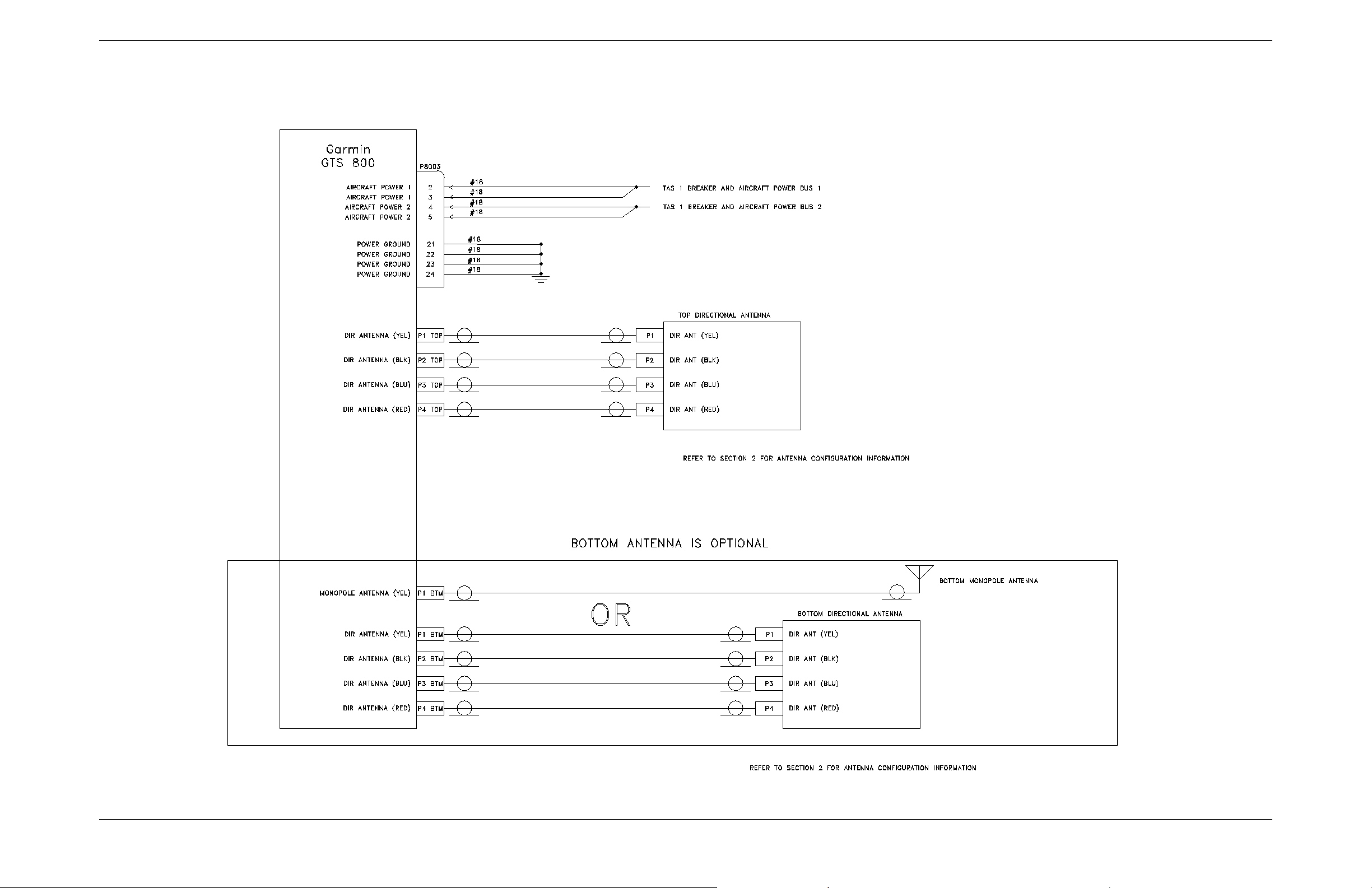
APPENDIX B INTERCONNECT EXAMPLE
Figure B-3. GTS 800 Example Interconnect
GTS 8XX/GPA 65 Installation Manual Page B-5 (Page B-6 blank)
190-00587-00 Revision 4TP
Page 79
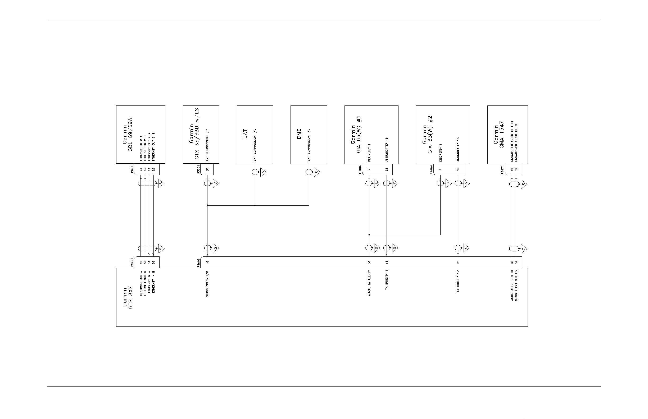
APPENDIX B INTERCONNECT EXAMPLE
Figure B-4. GTS 8XX G1000 Example Interconnect
GTS 8XX/GPA 65 Installation Manual Page B-7 (Page B-8 blank)
190-00587-00 Revision 4TP
Page 80
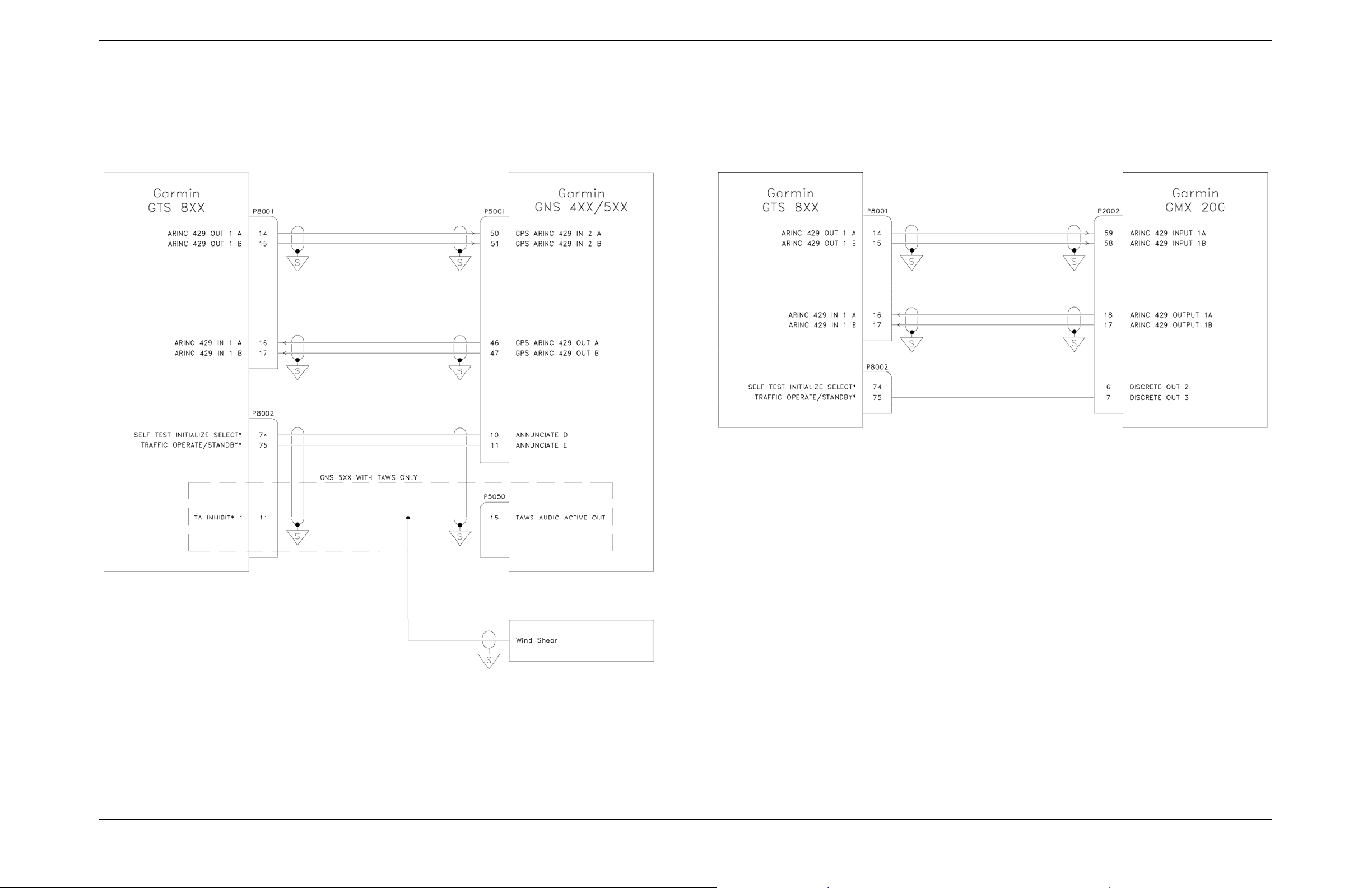
APPENDIX B INTERCONNECT EXAMPLE
Figure B-5. GTS 8XX GNS 4XX/GNS 5XX/GMX 200 Example Interconnect
GTS 8XX/GPA 65 Installation Manual Page B-9 (Page B-10 blank)
190-00587-00 Revision 4TP
Page 81
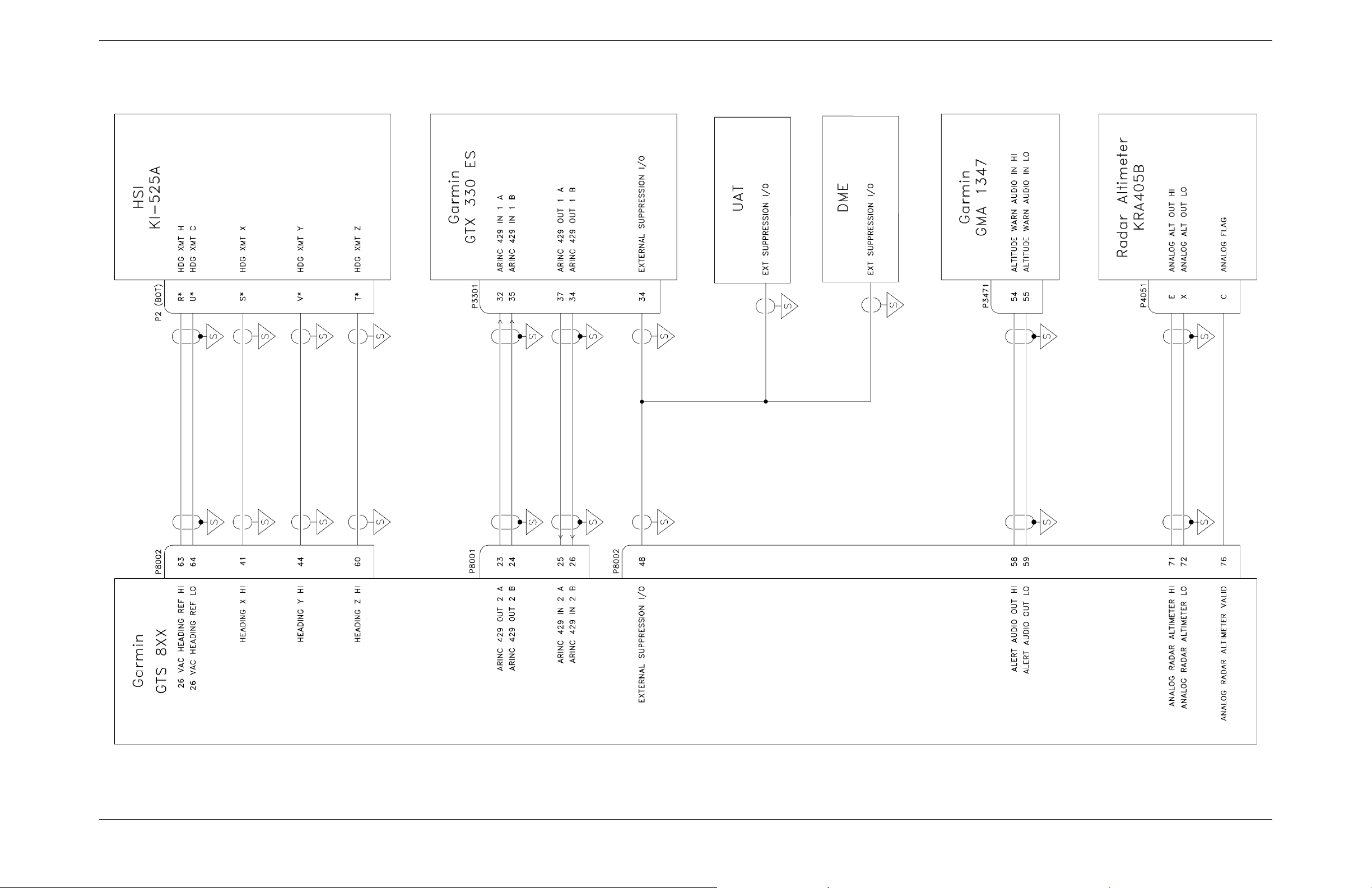
APPENDIX B INTERCONNECT EXAMPLE
Figure B-6. GTS 8XX/GMA/HSI/Altimeter Example Interconnect
GTS 8XX/GPA 65 Installation Manual Page B-11 (Page B-12 blank)
190-00587-00 Revision 4TP
Page 82
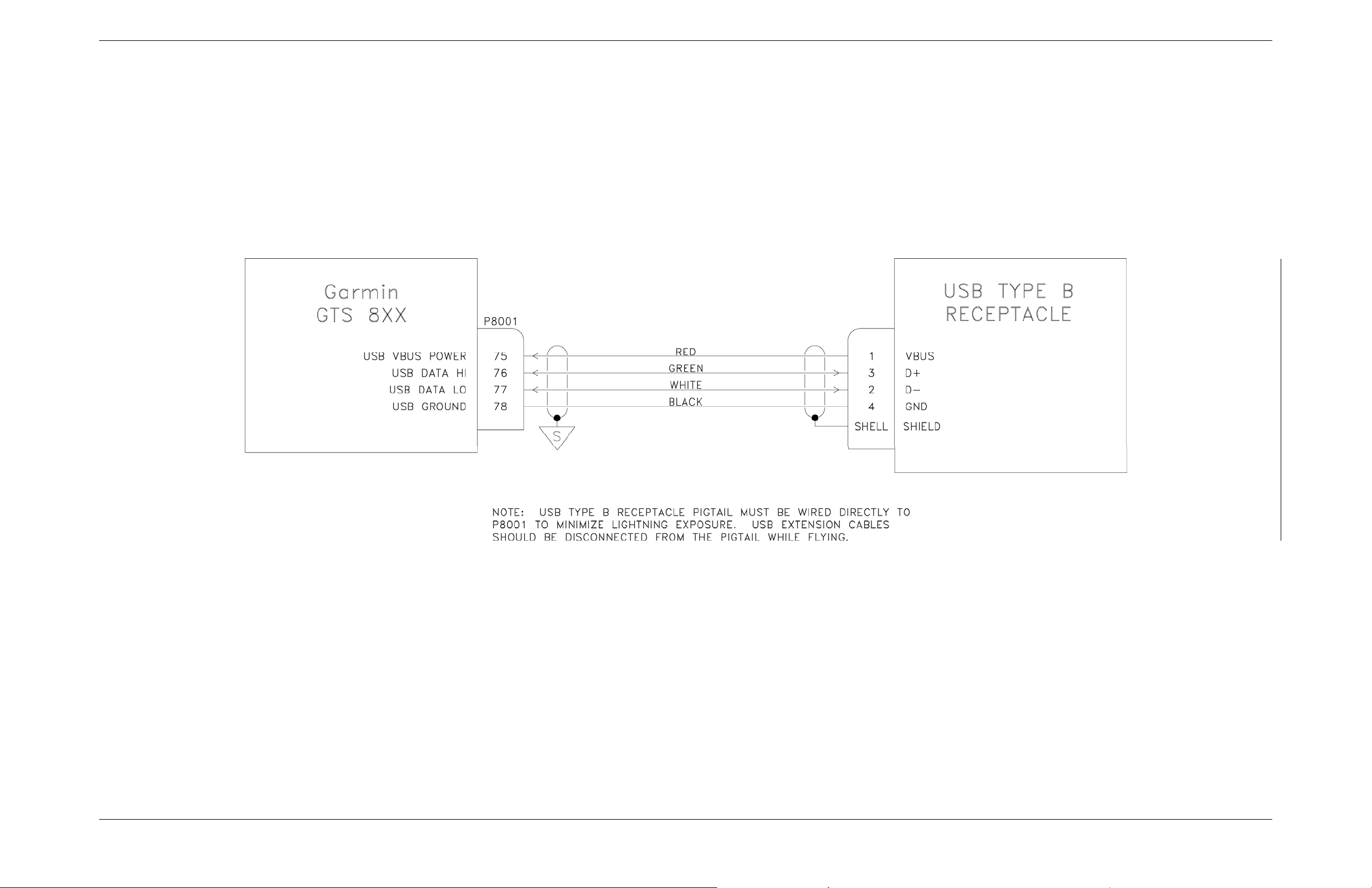
APPENDIX B INTERCONNECT EXAMPLE
Figure B-7. GTS 8XX Dongle Cable (Non-G1000 Installations Only)
GTS 8XX/GPA 65 Installation Manual Page B-13 (Page B-14 blank)
190-00587-00 Revision 4TP
Page 83
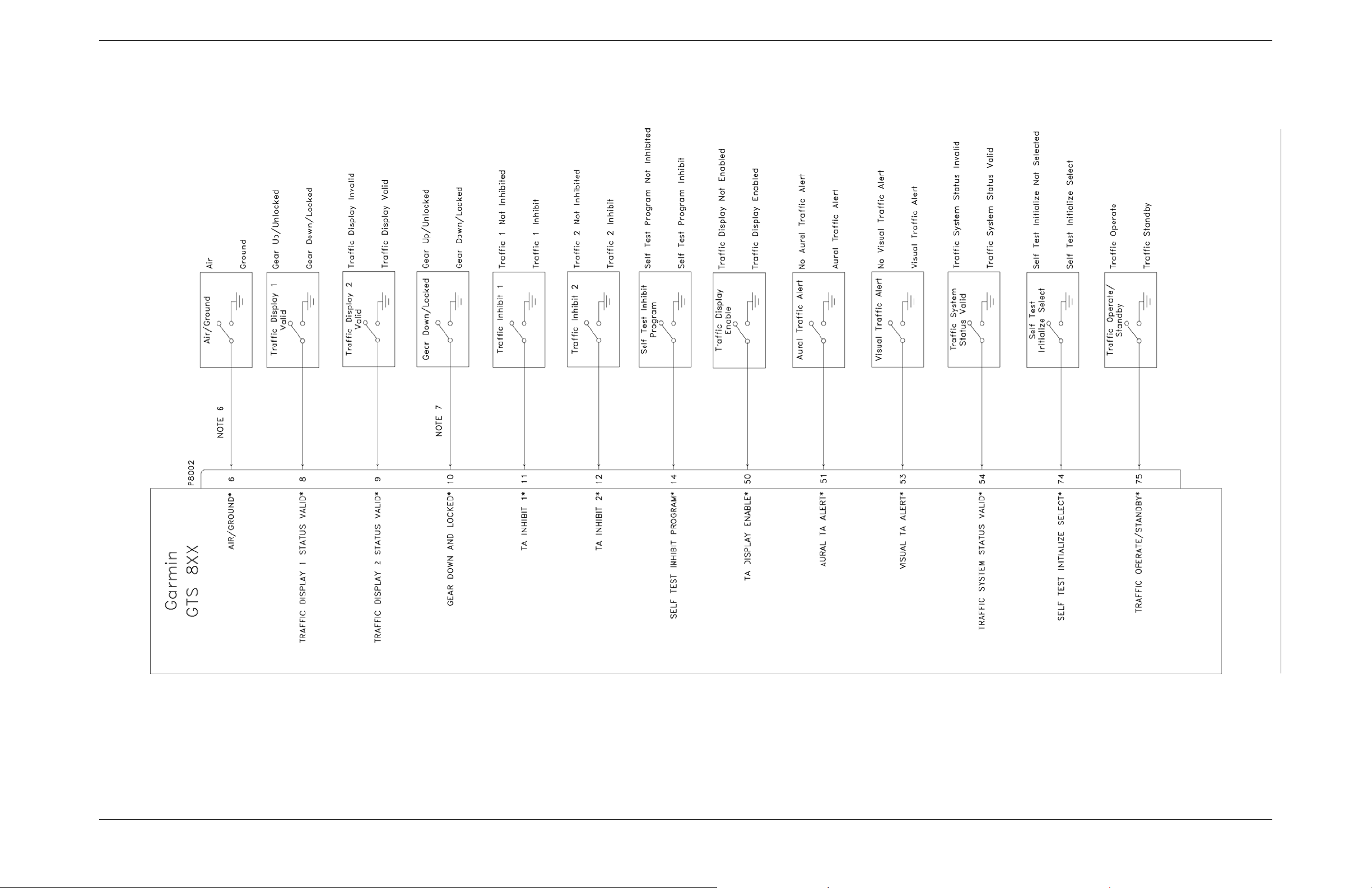
APPENDIX B INTERCONNECT EXAMPLE
Figure B-8. GTS 8XX Discrete Interconnects
GTS 8XX/GPA 65 Installation Manual Page B-15 (Page B-16 blank)
190-00587-00 Revision 4TP
Page 84
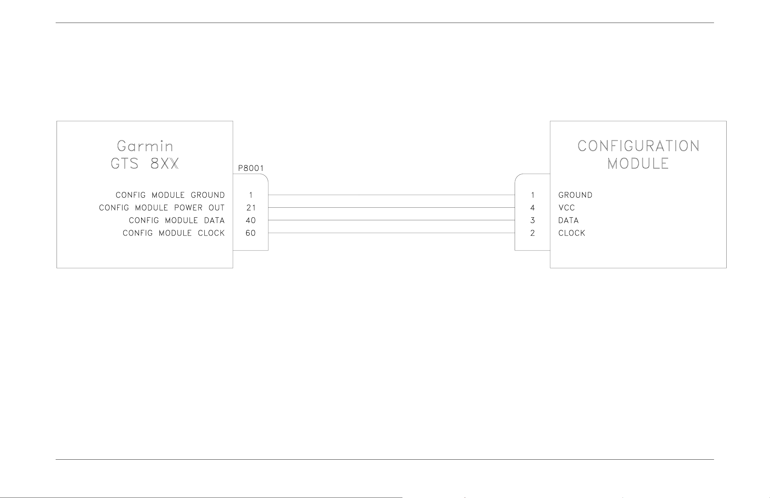
APPENDIX B INTERCONNECT EXAMPLE
The Configuration Module is only applicable for retrofit installtions
Figure B-9. GTS 8XX Config Module Example Interconnect
GTS 8XX/GPA 65 Installation Manual Page B-17 (Page B-18 blank)
190-00587-00 Revision 4TP
 Loading...