

Page 1

WELCOME . . . . . . . . . . . . . . . . . . . . . . . . . . . . . . . . . . . . . . . . . . . . . . . . . . . . . . .10
CONTROLLABLE UNITED STATES SUBMARINES . . . . . . . . . . . . . . . . . . . . . . . . . . . . . . . .10
CONTROLLABLE RUSSIAN SUBMARINES . . . . . . . . . . . . . . . . . . . . . . . . . . . . . . . . . . . . .10
MANUAL STRUCTURE – AN OVERVIEW . . . . . . . . . . . . . . . . . . . . . . . . . . . . . . . . . . . . . . .10
GAMEPLAY OVERVIEW . . . . . . . . . . . . . . . . . . . . . . . . . . . . . . . . . . . . . . . . . . . . .11
TERMS DEFINED . . . . . . . . . . . . . . . . . . . . . . . . . . . . . . . . . . . . . . . . . . . . . . . . . . . . . . .12
3D AND THE NAVIGATION MAP . . . . . . . . . . . . . . . . . . . . . . . . . . . . . . . . . . . . . . . . . . . . .13
WHAT YOU SEE ISN’T ALWAYS WHAT IS THERE! . . . . . . . . . . . . . . . . . . . . . . . . . . . . .13
3D VIEW IN A SUB GAME? . . . . . . . . . . . . . . . . . . . . . . . . . . . . . . . . . . . . . . . . . . . .14
OVERVIEW OF SHIP STATIONS . . . . . . . . . . . . . . . . . . . . . . . . . . . . . . . . . . . . . . . . . . . . .15
TASK BAR . . . . . . . . . . . . . . . . . . . . . . . . . . . . . . . . . . . . . . . . . . . . . . . . . . . . . . . .15
NAVIGATION . . . . . . . . . . . . . . . . . . . . . . . . . . . . . . . . . . . . . . . . . . . . . . . . . . . . . .15
SHIP CONTROL . . . . . . . . . . . . . . . . . . . . . . . . . . . . . . . . . . . . . . . . . . . . . . . . . . . .15
SONAR: BROADBAND . . . . . . . . . . . . . . . . . . . . . . . . . . . . . . . . . . . . . . . . . . . . . . .15
SONAR: NARROWBAND . . . . . . . . . . . . . . . . . . . . . . . . . . . . . . . . . . . . . . . . . . . . . .15
SONAR: DEMON . . . . . . . . . . . . . . . . . . . . . . . . . . . . . . . . . . . . . . . . . . . . . . . . . . .16
SONAR:ACTIVE . . . . . . . . . . . . . . . . . . . . . . . . . . . . . . . . . . . . . . . . . . . . . . . . . . . .16
SONAR:ACTIVE INTERCEPT . . . . . . . . . . . . . . . . . . . . . . . . . . . . . . . . . . . . . . . . . . .16
SONAR: SSP . . . . . . . . . . . . . . . . . . . . . . . . . . . . . . . . . . . . . . . . . . . . . . . . . . . . . .16
TMA . . . . . . . . . . . . . . . . . . . . . . . . . . . . . . . . . . . . . . . . . . . . . . . . . . . . . . . . . . . .16
FIRE CONTROL:TARGET DISPLAY . . . . . . . . . . . . . . . . . . . . . . . . . . . . . . . . . . . . . . .16
FIRE CONTROL: LAUNCH PANEL . . . . . . . . . . . . . . . . . . . . . . . . . . . . . . . . . . . . . . . .16
FIRE CONTROL: COUNTERMEASURE LAUNCHER (SEAWOLF ONLY) . . . . . . . . . . . . . . .16
FIRE CONTROL:WEAPON STORES . . . . . . . . . . . . . . . . . . . . . . . . . . . . . . . . . . . . . .17
RADAR . . . . . . . . . . . . . . . . . . . . . . . . . . . . . . . . . . . . . . . . . . . . . . . . . . . . . . . . . .17
RADIO/ESM . . . . . . . . . . . . . . . . . . . . . . . . . . . . . . . . . . . . . . . . . . . . . . . . . . . . . . .17
PERISCOPE/STADIMETER . . . . . . . . . . . . . . . . . . . . . . . . . . . . . . . . . . . . . . . . . . . . .17
UNDER ICE DISPLAY . . . . . . . . . . . . . . . . . . . . . . . . . . . . . . . . . . . . . . . . . . . . . . . .17
1
Page 2

AUTO CREW ASSISTANCE . . . . . . . . . . . . . . . . . . . . . . . . . . . . . . . . . . . . . . . . . . . . . . . .18
MISSION STATUS . . . . . . . . . . . . . . . . . . . . . . . . . . . . . . . . . . . . . . . . . . . . . . . . . . . . . .18
ENDING A MISSION . . . . . . . . . . . . . . . . . . . . . . . . . . . . . . . . . . . . . . . . . . . . . . . . . . . . .18
MISSION DEBRIEF . . . . . . . . . . . . . . . . . . . . . . . . . . . . . . . . . . . . . . . . . . . . . . . . . . . . . .19
STATUS SCREEN . . . . . . . . . . . . . . . . . . . . . . . . . . . . . . . . . . . . . . . . . . . . . . . . . . .19
REPLAY SCREEN . . . . . . . . . . . . . . . . . . . . . . . . . . . . . . . . . . . . . . . . . . . . . . . . . . .19
MAIN MENU . . . . . . . . . . . . . . . . . . . . . . . . . . . . . . . . . . . . . . . . . . . . . . . . . . . . . .20
CHOOSE PLAYER NAME . . . . . . . . . . . . . . . . . . . . . . . . . . . . . . . . . . . . . . . . . . . . . . . . . .20
MISSIONS . . . . . . . . . . . . . . . . . . . . . . . . . . . . . . . . . . . . . . . . . . . . . . . . . . . . . . . . . . . .20
TRAINING MISSIONS . . . . . . . . . . . . . . . . . . . . . . . . . . . . . . . . . . . . . . . . . . . . . . . .22
SINGLE MISSIONS . . . . . . . . . . . . . . . . . . . . . . . . . . . . . . . . . . . . . . . . . . . . . . . . . .22
SAVED MISSIONS . . . . . . . . . . . . . . . . . . . . . . . . . . . . . . . . . . . . . . . . . . . . . . . . . .23
MISSION BRIEF . . . . . . . . . . . . . . . . . . . . . . . . . . . . . . . . . . . . . . . . . . . . . . . .23
WEAPONS LOADOUT . . . . . . . . . . . . . . . . . . . . . . . . . . . . . . . . . . . . . . . . . . . . . . . .24
CAMPAIGN . . . . . . . . . . . . . . . . . . . . . . . . . . . . . . . . . . . . . . . . . . . . . . . . . . . . . . . . . . .25
THE STAGE WAS SET . . . . . . . . . . . . . . . . . . . . . . . . . . . . . . . . . . . . . . . . . . . . . . . .25
RUSSIA RESURGENT . . . . . . . . . . . . . . . . . . . . . . . . . . . . . . . . . . . . . . . . . . . . . . . .26
CAMPAIGN ORGANIZATION . . . . . . . . . . . . . . . . . . . . . . . . . . . . . . . . . . . . . . . . . . . .26
MULTIPLAYER . . . . . . . . . . . . . . . . . . . . . . . . . . . . . . . . . . . . . . . . . . . . . . . . . . . . . . . . .27
MISSION EDITOR . . . . . . . . . . . . . . . . . . . . . . . . . . . . . . . . . . . . . . . . . . . . . . . . . . . . . . .28
PLAYER’S LOG . . . . . . . . . . . . . . . . . . . . . . . . . . . . . . . . . . . . . . . . . . . . . . . . . . . . . . . .28
OPTIONS . . . . . . . . . . . . . . . . . . . . . . . . . . . . . . . . . . . . . . . . . . . . . . . . . . . . . . . . . . . . .29
CHANGING HOT KEY ASSIGNMENTS . . . . . . . . . . . . . . . . . . . . . . . . . . . . . . . . . . . . .31
SAVING OPTIONS CHANGES AND RESTORING DEFAULTS . . . . . . . . . . . . . . . . . . . . . .32
NOVICE AND ADVANCED DEFAULTS . . . . . . . . . . . . . . . . . . . . . . . . . . . . . . . . . . . . .32
USNI REFERENCE . . . . . . . . . . . . . . . . . . . . . . . . . . . . . . . . . . . . . . . . . . . . . . . . . . . . . .32
USING THE BROWSER . . . . . . . . . . . . . . . . . . . . . . . . . . . . . . . . . . . . . . . . . . . . . . .32
PLATFORM-SPECIFIC INFORMATION . . . . . . . . . . . . . . . . . . . . . . . . . . . . . . . . . . . . .33
EXIT . . . . . . . . . . . . . . . . . . . . . . . . . . . . . . . . . . . . . . . . . . . . . . . . . . . . . . . . . . . . . . . .34
SHIP STATIONS . . . . . . . . . . . . . . . . . . . . . . . . . . . . . . . . . . . . . . . . . . . . . . . . . . .34
GENERAL INFORMATION . . . . . . . . . . . . . . . . . . . . . . . . . . . . . . . . . . . . . . . . . . . . . . . . .34
SELECTED OPTIONS . . . . . . . . . . . . . . . . . . . . . . . . . . . . . . . . . . . . . . . . . . . . . . . .34
SYSTEM MENU . . . . . . . . . . . . . . . . . . . . . . . . . . . . . . . . . . . . . . . . . . . . . . . . . . . .34
SEAWOLF BUTTON MATRIX . . . . . . . . . . . . . . . . . . . . . . . . . . . . . . . . . . . . . . . . . . .35
MANUAL DESCRIPTIONS . . . . . . . . . . . . . . . . . . . . . . . . . . . . . . . . . . . . . . . . . . . . .35
TASK BAR . . . . . . . . . . . . . . . . . . . . . . . . . . . . . . . . . . . . . . . . . . . . . . . . . . . . . . . . . . . .35
STATIONS MENU . . . . . . . . . . . . . . . . . . . . . . . . . . . . . . . . . . . . . . . . . . . . . . . . . . .36
ORDERS MENU . . . . . . . . . . . . . . . . . . . . . . . . . . . . . . . . . . . . . . . . . . . . . . . . . . . .36
FIRE TUBE . . . . . . . . . . . . . . . . . . . . . . . . . . . . . . . . . . . . . . . . . . . . . . . . . . . .36
NAVIGATE . . . . . . . . . . . . . . . . . . . . . . . . . . . . . . . . . . . . . . . . . . . . . . . . . . . .37
MASTS AND ANTENNAS . . . . . . . . . . . . . . . . . . . . . . . . . . . . . . . . . . . . . . . . . .37
COUNTERMEASURES . . . . . . . . . . . . . . . . . . . . . . . . . . . . . . . . . . . . . . . . . . . .38
2
Page 3

HISTORY DISPLAY . . . . . . . . . . . . . . . . . . . . . . . . . . . . . . . . . . . . . . . . . . . . . . . . . .38
HISTORY SELECTION BUTTONS . . . . . . . . . . . . . . . . . . . . . . . . . . . . . . . . . . . . .38
HISTORY WINDOW . . . . . . . . . . . . . . . . . . . . . . . . . . . . . . . . . . . . . . . . . . . . . .39
MANEUVER SHORTCUTS AND GAME READOUTS . . . . . . . . . . . . . . . . . . . . . . . . . . . .39
DEPTH, COURSE AND SPEED . . . . . . . . . . . . . . . . . . . . . . . . . . . . . . . . . . . . . .39
KEEL . . . . . . . . . . . . . . . . . . . . . . . . . . . . . . . . . . . . . . . . . . . . . . . . . . . . . . .39
GAME TIME/PAUSE INDICATOR . . . . . . . . . . . . . . . . . . . . . . . . . . . . . . . . . . . . .40
TIME COMPRESSION SCALE . . . . . . . . . . . . . . . . . . . . . . . . . . . . . . . . . . . . . . .40
NAVIGATION STATION . . . . . . . . . . . . . . . . . . . . . . . . . . . . . . . . . . . . . . . . . . . . . . . . . . .40
2D MAP . . . . . . . . . . . . . . . . . . . . . . . . . . . . . . . . . . . . . . . . . . . . . . . . . . . . . . . . .41
MAP MENU . . . . . . . . . . . . . . . . . . . . . . . . . . . . . . . . . . . . . . . . . . . . . . . . . . .41
NAV MAP CONTACTS . . . . . . . . . . . . . . . . . . . . . . . . . . . . . . . . . . . . . . . . . . . .42
CONTACT SYMBOLS . . . . . . . . . . . . . . . . . . . . . . . . . . . . . . . . . . . . . . . . . . . .43
CONTACT MENU . . . . . . . . . . . . . . . . . . . . . . . . . . . . . . . . . . . . . . . . . . . . . . .45
OWNSHIP MENU . . . . . . . . . . . . . . . . . . . . . . . . . . . . . . . . . . . . . . . . . . . . . . .46
DATA DISPLAY INDICATOR (DDI) . . . . . . . . . . . . . . . . . . . . . . . . . . . . . . . . . . . . . . . .47
3D VIEW . . . . . . . . . . . . . . . . . . . . . . . . . . . . . . . . . . . . . . . . . . . . . . . . . . . . . . . . .48
3D VIEW CONTROLS . . . . . . . . . . . . . . . . . . . . . . . . . . . . . . . . . . . . . . . . . . . .48
DISABLING AND HIDING 3D . . . . . . . . . . . . . . . . . . . . . . . . . . . . . . . . . . . . . . . .49
PLAYING FROM THE NAV STATION . . . . . . . . . . . . . . . . . . . . . . . . . . . . . . . . . . . . . .50
ATTACKING SEA TARGETS FROM NAV . . . . . . . . . . . . . . . . . . . . . . . . . . . . . . . .50
LAUNCHING LAND ATTACK MISSILES FROM NAV . . . . . . . . . . . . . . . . . . . . . . . . .50
OWNSHIP WAYPOINTS . . . . . . . . . . . . . . . . . . . . . . . . . . . . . . . . . . . . . . . . . . .50
VOICE COMMANDS . . . . . . . . . . . . . . . . . . . . . . . . . . . . . . . . . . . . . . . . . . . . .51
SHIP CONTROL . . . . . . . . . . . . . . . . . . . . . . . . . . . . . . . . . . . . . . . . . . . . . . . . . . . . . . . .52
SHIP CONTROL TASKS . . . . . . . . . . . . . . . . . . . . . . . . . . . . . . . . . . . . . . . . . . . . . . .52
SEAWOLF:SHIP CONTROL STATION . . . . . . . . . . . . . . . . . . . . . . . . . . . . . . . . . . . . .53
688(I): SHIP CONTROL STATION . . . . . . . . . . . . . . . . . . . . . . . . . . . . . . . . . . . . . . . .55
AKULA: SHIP CONTROL . . . . . . . . . . . . . . . . . . . . . . . . . . . . . . . . . . . . . . . . . . . . . .57
SONAR STATIONS . . . . . . . . . . . . . . . . . . . . . . . . . . . . . . . . . . . . . . . . . . . . . . . . . . . . . .58
SONAR STATION SELECTION BUTTONS . . . . . . . . . . . . . . . . . . . . . . . . . . . . . . . . . . .59
ABOUT SONAR . . . . . . . . . . . . . . . . . . . . . . . . . . . . . . . . . . . . . . . . . . . . . . . . . . . .59
SONAR ARRAYS . . . . . . . . . . . . . . . . . . . . . . . . . . . . . . . . . . . . . . . . . . . . . . . .60
SONAR LIMITATIONS . . . . . . . . . . . . . . . . . . . . . . . . . . . . . . . . . . . . . . . . . . . .61
BROADBAND SONAR . . . . . . . . . . . . . . . . . . . . . . . . . . . . . . . . . . . . . . . . . . . . . . . .62
SEAWOLF AND 688(I):BROADBAND WATERFALL DISPLAYS . . . . . . . . . . . . . . . . .62
AKULA: BROADBAND CIRCULAR SSAZ DISPLAY . . . . . . . . . . . . . . . . . . . . . . . . .63
ASSIGNING TRACKERS . . . . . . . . . . . . . . . . . . . . . . . . . . . . . . . . . . . . . . . . . . .64
TOWED ARRAY CONTACTS . . . . . . . . . . . . . . . . . . . . . . . . . . . . . . . . . . . . . . . .65
SEAWOLF:BROADBAND STATION . . . . . . . . . . . . . . . . . . . . . . . . . . . . . . . . . . .65
688(I): BROADBAND STATION . . . . . . . . . . . . . . . . . . . . . . . . . . . . . . . . . . . . . .67
AKULA: BROADBAND STATION . . . . . . . . . . . . . . . . . . . . . . . . . . . . . . . . . . . . .68
3
Page 4

NARROWBAND SONAR . . . . . . . . . . . . . . . . . . . . . . . . . . . . . . . . . . . . . . . . . . . . . .69
SEAWOLF:NARROWBAND SONAR . . . . . . . . . . . . . . . . . . . . . . . . . . . . . . . . . . .69
688(I): NARROWBAND SONAR . . . . . . . . . . . . . . . . . . . . . . . . . . . . . . . . . . . . . .72
AKULA: NARROWBAND SONAR . . . . . . . . . . . . . . . . . . . . . . . . . . . . . . . . . . . . .75
DEMON SONAR STATION . . . . . . . . . . . . . . . . . . . . . . . . . . . . . . . . . . . . . . . . . . . . .77
SEAWOLF DEMON DISPLAY . . . . . . . . . . . . . . . . . . . . . . . . . . . . . . . . . . . . . . .80
688(I) DEMON DISPLAY . . . . . . . . . . . . . . . . . . . . . . . . . . . . . . . . . . . . . . . . . .81
AKULA DEMON DISPLAY . . . . . . . . . . . . . . . . . . . . . . . . . . . . . . . . . . . . . . . . . .82
ACTIVE SONAR STATION . . . . . . . . . . . . . . . . . . . . . . . . . . . . . . . . . . . . . . . . . . . . .83
MEDIUM FREQUENCY (MF) ACTIVE SONAR . . . . . . . . . . . . . . . . . . . . . . . . . . . . .83
HIGH FREQUENCY ACTIVE SONAR (HFAS) . . . . . . . . . . . . . . . . . . . . . . . . . . . . . .83
USING MEDIUM FREQUENCY ACTIVE SONAR . . . . . . . . . . . . . . . . . . . . . . . . . . . .83
SEAWOLF AND 688(I):MF ACTIVE SONAR DISPLAYS . . . . . . . . . . . . . . . . . . . . . .83
AKULA: MEDIUM FREQUENCY ACTIVE SONAR DISPLAY . . . . . . . . . . . . . . . . . . . .84
ACTIVE SONAR CONTACTS . . . . . . . . . . . . . . . . . . . . . . . . . . . . . . . . . . . . . . . .84
SEAWOLF:ACTIVE SONAR STATION . . . . . . . . . . . . . . . . . . . . . . . . . . . . . . . . . .87
SEAWOLF:HIGH FREQUENCY ACTIVE SONAR . . . . . . . . . . . . . . . . . . . . . . . . . . .88
688(I):ACTIVE SONAR STATION . . . . . . . . . . . . . . . . . . . . . . . . . . . . . . . . . . . . .89
688(I): HIGH FREQUENCY ACTIVE SONAR . . . . . . . . . . . . . . . . . . . . . . . . . . . . . .90
AKULA:ACTIVE SONAR STATION . . . . . . . . . . . . . . . . . . . . . . . . . . . . . . . . . . . .91
AKULA: HIGH FREQUENCY ACTIVE SONAR . . . . . . . . . . . . . . . . . . . . . . . . . . . . .91
ACTIVE INTERCEPT SONAR STATION . . . . . . . . . . . . . . . . . . . . . . . . . . . . . . . . . . . . .91
ALL SUBS: BUTTONS AND LABELS . . . . . . . . . . . . . . . . . . . . . . . . . . . . . . . . . .92
SEAWOLF:ACTIVE INTERCEPT STATION . . . . . . . . . . . . . . . . . . . . . . . . . . . . . . .92
688(I) ACTIVE INTERCEPT STATION . . . . . . . . . . . . . . . . . . . . . . . . . . . . . . . . . .93
AKULA ACTIVE INTERCEPT STATION . . . . . . . . . . . . . . . . . . . . . . . . . . . . . . . . . .93
SSP SONAR STATION (SOUND SPEED PROFILE) . . . . . . . . . . . . . . . . . . . . . . . . . . . . .93
LAUNCHING AN XBT PROBE . . . . . . . . . . . . . . . . . . . . . . . . . . . . . . . . . . . . . . .94
SEAWOLF:SSP STATION . . . . . . . . . . . . . . . . . . . . . . . . . . . . . . . . . . . . . . . . . .94
688(I) SSP STATION . . . . . . . . . . . . . . . . . . . . . . . . . . . . . . . . . . . . . . . . . . . . .95
AKULA: SSP STATION . . . . . . . . . . . . . . . . . . . . . . . . . . . . . . . . . . . . . . . . . . . .95
UUV SONAR . . . . . . . . . . . . . . . . . . . . . . . . . . . . . . . . . . . . . . . . . . . . . . . . . . . . . .96
TARGET MOTION ANALYSES (TMA) STATION . . . . . . . . . . . . . . . . . . . . . . . . . . . . . . . . . . .96
HOW DOES TMA WORK? . . . . . . . . . . . . . . . . . . . . . . . . . . . . . . . . . . . . . . . . . . . . .97
THE TMA BOARD . . . . . . . . . . . . . . . . . . . . . . . . . . . . . . . . . . . . . . . . . . . . . . .98
THE TMA RULER . . . . . . . . . . . . . . . . . . . . . . . . . . . . . . . . . . . . . . . . . . . . . . .99
THE TMA DOT STACK . . . . . . . . . . . . . . . . . . . . . . . . . . . . . . . . . . . . . . . . . . .100
TMA ON RADAR,ACTIVE SONAR AND VISUAL CONTACTS . . . . . . . . . . . . . . . . . . . . .101
TMA ON PASSIVE SONAR AND ESM CONTACTS . . . . . . . . . . . . . . . . . . . . . . . . . . . .102
TMA ON UUV SENSOR CONTACTS . . . . . . . . . . . . . . . . . . . . . . . . . . . . . . . . . . . . .105
SEAWOLF:TMA STATION . . . . . . . . . . . . . . . . . . . . . . . . . . . . . . . . . . . . . . . . . . . .105
688(I) AND AKULA:TMA STATIONS . . . . . . . . . . . . . . . . . . . . . . . . . . . . . . . . . . . . .107
4
Page 5

FIRE CONTROL SUITE . . . . . . . . . . . . . . . . . . . . . . . . . . . . . . . . . . . . . . . . . . . . . . . . . .108
BASIC LAUNCH PROCEDURES . . . . . . . . . . . . . . . . . . . . . . . . . . . . . . . . . . . . . . . .108
BASIC LAUNCH PROCEDURES FOR SEA TARGETS . . . . . . . . . . . . . . . . . . . . . . . . . .109
BASIC LAUNCH PROCEDURES FOR LAND TARGETS . . . . . . . . . . . . . . . . . . . . . . . . .109
BASIC LAUNCH PROCEDURES FOR UUVS . . . . . . . . . . . . . . . . . . . . . . . . . . . . . . . .110
BASIC LAUNCH PROCEDURES FOR MINES . . . . . . . . . . . . . . . . . . . . . . . . . . . . . . . .110
TACTICAL WEAPONS . . . . . . . . . . . . . . . . . . . . . . . . . . . . . . . . . . . . . . . . . . . . . . .110
SEAWOLF AND 688(I) WEAPONS . . . . . . . . . . . . . . . . . . . . . . . . . . . . . . . . . . .110
AKULA WEAPONS . . . . . . . . . . . . . . . . . . . . . . . . . . . . . . . . . . . . . . . . . . . . .111
STRATEGIC WEAPONS . . . . . . . . . . . . . . . . . . . . . . . . . . . . . . . . . . . . . . . . . . . . . .112
MINES: SEAWOLF AND 668(I) . . . . . . . . . . . . . . . . . . . . . . . . . . . . . . . . . . . . .112
MINES:AKULA . . . . . . . . . . . . . . . . . . . . . . . . . . . . . . . . . . . . . . . . . . . . . . . .112
COUNTERMEASURES . . . . . . . . . . . . . . . . . . . . . . . . . . . . . . . . . . . . . . . . . . . . . . .112
BASIC STEPS FOR LAUNCHING COUNTERMEASURES . . . . . . . . . . . . . . . . . . . . .112
PRESETS . . . . . . . . . . . . . . . . . . . . . . . . . . . . . . . . . . . . . . . . . . . . . . . . . . . . . . .113
ANTISHIP MISSILE PRESETS . . . . . . . . . . . . . . . . . . . . . . . . . . . . . . . . . . . . . .113
COUNTERMEASURE PRESETS (SEAWOLF ONLY) . . . . . . . . . . . . . . . . . . . . . . . .113
LAND ATTACK MISSILE PRESETS . . . . . . . . . . . . . . . . . . . . . . . . . . . . . . . . . . .113
MINE PRESETS . . . . . . . . . . . . . . . . . . . . . . . . . . . . . . . . . . . . . . . . . . . . . . .114
MISSILE-TORPEDO PRESETS . . . . . . . . . . . . . . . . . . . . . . . . . . . . . . . . . . . . . .114
ROCKET TORPEDO PRESETS . . . . . . . . . . . . . . . . . . . . . . . . . . . . . . . . . . . . . .114
TORPEDO PRESETS . . . . . . . . . . . . . . . . . . . . . . . . . . . . . . . . . . . . . . . . . . . .114
UUV PRESETS . . . . . . . . . . . . . . . . . . . . . . . . . . . . . . . . . . . . . . . . . . . . . . . .115
FIRE CONTROL MAP . . . . . . . . . . . . . . . . . . . . . . . . . . . . . . . . . . . . . . . . . . . . . . .115
CONTACTS WITH LINES OF BEARING . . . . . . . . . . . . . . . . . . . . . . . . . . . . . . . .115
SEAWOLF:FIRE CONTROL SUITE . . . . . . . . . . . . . . . . . . . . . . . . . . . . . . . . . . . . . .115
SEAWOLF:TARGET DISPLAY . . . . . . . . . . . . . . . . . . . . . . . . . . . . . . . . . . . . . .116
SEAWOLF:LAUNCH PANEL . . . . . . . . . . . . . . . . . . . . . . . . . . . . . . . . . . . . . . .118
SEAWOLF:COUNTERMEASURE LAUNCH PANEL . . . . . . . . . . . . . . . . . . . . . . . .120
SEAWOLF:WEAPON INVENTORY . . . . . . . . . . . . . . . . . . . . . . . . . . . . . . . . . . .121
688(I): FIRE CONTROL SUITE . . . . . . . . . . . . . . . . . . . . . . . . . . . . . . . . . . . . . . . . .121
688(I):TARGET DISPLAY . . . . . . . . . . . . . . . . . . . . . . . . . . . . . . . . . . . . . . . . .121
688(I): LAUNCH PANEL . . . . . . . . . . . . . . . . . . . . . . . . . . . . . . . . . . . . . . . . . .123
688(I):WEAPON INVENTORY . . . . . . . . . . . . . . . . . . . . . . . . . . . . . . . . . . . . . .124
AKULA: FIRE CONTROL SUITE . . . . . . . . . . . . . . . . . . . . . . . . . . . . . . . . . . . . . . . . .125
AKULA:TARGET DISPLAY . . . . . . . . . . . . . . . . . . . . . . . . . . . . . . . . . . . . . . . .125
AKULA: LAUNCH PANEL . . . . . . . . . . . . . . . . . . . . . . . . . . . . . . . . . . . . . . . . .127
AKULA:WEAPON INVENTORY . . . . . . . . . . . . . . . . . . . . . . . . . . . . . . . . . . . . .128
RADAR STATION . . . . . . . . . . . . . . . . . . . . . . . . . . . . . . . . . . . . . . . . . . . . . . . . . . . . . .129
RADIO ROOM/ESM STATION . . . . . . . . . . . . . . . . . . . . . . . . . . . . . . . . . . . . . . . . . . . . .131
RADIO MESSAGES . . . . . . . . . . . . . . . . . . . . . . . . . . . . . . . . . . . . . . . . . . . . . . . . .131
RECEIVING RADIO MESSAGES . . . . . . . . . . . . . . . . . . . . . . . . . . . . . . . . . . . . . . . .131
5
Page 6

ELECTRONIC SUPPORT MEASURES (ESM) . . . . . . . . . . . . . . . . . . . . . . . . . . . . . . . .132
DETECTING AND CLASSIFYING CONTACTS WITH ESM . . . . . . . . . . . . . . . . . . . . . . .132
SEAWOLF:RADIO/ESM STATION . . . . . . . . . . . . . . . . . . . . . . . . . . . . . . . . . . . . . . .133
688(I): RADIO/ESM STATION . . . . . . . . . . . . . . . . . . . . . . . . . . . . . . . . . . . . . . . . . .134
AKULA: RADIO/ESM STATION . . . . . . . . . . . . . . . . . . . . . . . . . . . . . . . . . . . . . . . . .135
PERISCOPE AND STADIMETER STATIONS . . . . . . . . . . . . . . . . . . . . . . . . . . . . . . . . . . . .136
DETECTING CONTACTS WITH THE PERISCOPE . . . . . . . . . . . . . . . . . . . . . . . . . . . . .136
SEAWOLF:PERISCOPE STATION . . . . . . . . . . . . . . . . . . . . . . . . . . . . . . . . . . . . . . .138
688(I) PERISCOPE STATION . . . . . . . . . . . . . . . . . . . . . . . . . . . . . . . . . . . . . . . . . .139
AKULA: PERISCOPE STATION . . . . . . . . . . . . . . . . . . . . . . . . . . . . . . . . . . . . . . . . .140
STADIMETER STATION . . . . . . . . . . . . . . . . . . . . . . . . . . . . . . . . . . . . . . . . . . . . . .141
DETERMINING COURSE WITH STADIMETER . . . . . . . . . . . . . . . . . . . . . . . . . . . .141
SEAWOLF:STADIMETER STATION . . . . . . . . . . . . . . . . . . . . . . . . . . . . . . . . . .142
688(I): STADIMETER STATION . . . . . . . . . . . . . . . . . . . . . . . . . . . . . . . . . . . . .143
AKULA: STADIMETER STATION . . . . . . . . . . . . . . . . . . . . . . . . . . . . . . . . . . . . .144
CLASSIFYING ACONTACTUSING THE STADIMETER . . . . . . . . . . . . . . . . . . . . . .144
UNDER ICE DISPLAY . . . . . . . . . . . . . . . . . . . . . . . . . . . . . . . . . . . . . . . . . . . . . . . . . . .145
SEAWOLF:UNDER ICE DISPLAY . . . . . . . . . . . . . . . . . . . . . . . . . . . . . . . . . . . . . . .145
688(I): UNDER ICE DISPLAY . . . . . . . . . . . . . . . . . . . . . . . . . . . . . . . . . . . . . . . . . .145
AKULA: UNDER ICE DISPLAY . . . . . . . . . . . . . . . . . . . . . . . . . . . . . . . . . . . . . . . . . .145
AUTO CREWMEN . . . . . . . . . . . . . . . . . . . . . . . . . . . . . . . . . . . . . . . . . . . . . . . . . . . . . .146
SONAR AUTO CREWMAN . . . . . . . . . . . . . . . . . . . . . . . . . . . . . . . . . . . . . . . . . . . .146
TMA AUTO CREWMAN . . . . . . . . . . . . . . . . . . . . . . . . . . . . . . . . . . . . . . . . . . . . . .147
FIRE CONTROL AUTO CREWMAN . . . . . . . . . . . . . . . . . . . . . . . . . . . . . . . . . . . . . .147
RADAR AUTO CREWMAN . . . . . . . . . . . . . . . . . . . . . . . . . . . . . . . . . . . . . . . . . . . .147
AUTO-HELMSMAN . . . . . . . . . . . . . . . . . . . . . . . . . . . . . . . . . . . . . . . . . . . . . . . . .148
SPECIAL OPERATIONS AND PROCEDURES . . . . . . . . . . . . . . . . . . . . . . . . . . .148
DEPLOYING AND RECOVERING SPECIAL FORCES . . . . . . . . . . . . . . . . . . . . . . . . . . . . . .148
TO LAUNCH SPECIAL FORCES TEAM . . . . . . . . . . . . . . . . . . . . . . . . . . . . . . . . . . . .148
TO RETRIEVE SPECIAL FORCES TEAM . . . . . . . . . . . . . . . . . . . . . . . . . . . . . . . . . . .149
DEPLOYING UUVS . . . . . . . . . . . . . . . . . . . . . . . . . . . . . . . . . . . . . . . . . . . . . . . . . . . . .149
TO LAUNCH A UUV . . . . . . . . . . . . . . . . . . . . . . . . . . . . . . . . . . . . . . . . . . . . . . . . .150
TO ENABLE UUV ACTIVE SONAR . . . . . . . . . . . . . . . . . . . . . . . . . . . . . . . . . . . . . . .150
LAYING MINES . . . . . . . . . . . . . . . . . . . . . . . . . . . . . . . . . . . . . . . . . . . . . . . . . . . . . . .150
TO LAY A MINEFIELD . . . . . . . . . . . . . . . . . . . . . . . . . . . . . . . . . . . . . . . . . . . . . . .151
DSRV RESCUES . . . . . . . . . . . . . . . . . . . . . . . . . . . . . . . . . . . . . . . . . . . . . . . . . . . . . . .151
UNDER ICE OPERATIONS . . . . . . . . . . . . . . . . . . . . . . . . . . . . . . . . . . . . . . . . . . . . . . . .152
TO SURFACE AND SUBMERGE UNDER THE ICE . . . . . . . . . . . . . . . . . . . . . . . . . . . .152
MULTIPLAYER . . . . . . . . . . . . . . . . . . . . . . . . . . . . . . . . . . . . . . . . . . . . . . . . . . .153
CONNECTING . . . . . . . . . . . . . . . . . . . . . . . . . . . . . . . . . . . . . . . . . . . . . . . . . . . . . . . .153
TO HOST AN IPX OR TCP/IP GAME . . . . . . . . . . . . . . . . . . . . . . . . . . . . . . . . . . . . . . . . .153
6
Page 7

LOBBY . . . . . . . . . . . . . . . . . . . . . . . . . . . . . . . . . . . . . . . . . . . . . . . . . . . . . . . . .154
GAME ROOM: HOST OPTIONS . . . . . . . . . . . . . . . . . . . . . . . . . . . . . . . . . . . . . . . . .154
TO JOIN A IPX OR TCP/IP GAME . . . . . . . . . . . . . . . . . . . . . . . . . . . . . . . . . . . . . . . . . . .155
LOBBY . . . . . . . . . . . . . . . . . . . . . . . . . . . . . . . . . . . . . . . . . . . . . . . . . . . . . . . . .155
GAME ROOM: JOIN OPTIONS . . . . . . . . . . . . . . . . . . . . . . . . . . . . . . . . . . . . . . . . .155
MULTIPLAYER MATCHUP GAMES . . . . . . . . . . . . . . . . . . . . . . . . . . . . . . . . . . . . . . . . . .156
MULTIPLAYER OPTIONS . . . . . . . . . . . . . . . . . . . . . . . . . . . . . . . . . . . . . . . . . . . . . . . . .157
MULTIPLAYER DEFAULT SETTINGS . . . . . . . . . . . . . . . . . . . . . . . . . . . . . . . . . . . . .159
CHAT . . . . . . . . . . . . . . . . . . . . . . . . . . . . . . . . . . . . . . . . . . . . . . . . . . . . . . . . . . . . . .159
MULTIPLAYER WARNING AND ERROR MESSAGES . . . . . . . . . . . . . . . . . . . . . . . . . . . . . .160
MISSION EDITOR . . . . . . . . . . . . . . . . . . . . . . . . . . . . . . . . . . . . . . . . . . . . . . . . .161
GETTING STARTED . . . . . . . . . . . . . . . . . . . . . . . . . . . . . . . . . . . . . . . . . . . . . . . . . . . .162
CREATING A NEW MISSION . . . . . . . . . . . . . . . . . . . . . . . . . . . . . . . . . . . . . . . . . .162
EDITING AN EXISTING MISSION . . . . . . . . . . . . . . . . . . . . . . . . . . . . . . . . . . . . . . .162
IMPORTING SCENARIOS . . . . . . . . . . . . . . . . . . . . . . . . . . . . . . . . . . . . . . . . . . . . .162
MISSION CREATION . . . . . . . . . . . . . . . . . . . . . . . . . . . . . . . . . . . . . . . . . . . . . . . . . . . .163
MISSION MAP . . . . . . . . . . . . . . . . . . . . . . . . . . . . . . . . . . . . . . . . . . . . . . . . . . . . . . . .164
MAP READOUTS . . . . . . . . . . . . . . . . . . . . . . . . . . . . . . . . . . . . . . . . . . . . . . . . . .164
MAP CONTROLS: . . . . . . . . . . . . . . . . . . . . . . . . . . . . . . . . . . . . . . . . . . . . . .164
MISSION MAP MENU . . . . . . . . . . . . . . . . . . . . . . . . . . . . . . . . . . . . . . . . . . . . . . .165
OBJECT BUTTONS . . . . . . . . . . . . . . . . . . . . . . . . . . . . . . . . . . . . . . . . . . . . . . . . . . . . .166
ADD SUBMARINE OR SHIP . . . . . . . . . . . . . . . . . . . . . . . . . . . . . . . . . . . . . . . . . . .166
ADD GLOBAL GOAL . . . . . . . . . . . . . . . . . . . . . . . . . . . . . . . . . . . . . . . . . . . . . . . .166
ADD BUILDING . . . . . . . . . . . . . . . . . . . . . . . . . . . . . . . . . . . . . . . . . . . . . . . . . . .166
MISSION OBJECT MENU . . . . . . . . . . . . . . . . . . . . . . . . . . . . . . . . . . . . . . . . . . . . . . . .167
ADD TO FORMATION . . . . . . . . . . . . . . . . . . . . . . . . . . . . . . . . . . . . . . . . . . . . . . .167
UNLINK FROM FORMATION . . . . . . . . . . . . . . . . . . . . . . . . . . . . . . . . . . . . . . . . . .167
ADD ATTACHED GOAL . . . . . . . . . . . . . . . . . . . . . . . . . . . . . . . . . . . . . . . . . . . . . .168
ADD INFLIGHT AIRCRAFT . . . . . . . . . . . . . . . . . . . . . . . . . . . . . . . . . . . . . . . . . . . .168
ADD AIR STATION . . . . . . . . . . . . . . . . . . . . . . . . . . . . . . . . . . . . . . . . . . . . . . . . .168
ADD AIR CORRIDOR (AIRPORT) . . . . . . . . . . . . . . . . . . . . . . . . . . . . . . . . . . . . . . . .169
FLIGHT SCHEDULE . . . . . . . . . . . . . . . . . . . . . . . . . . . . . . . . . . . . . . . . . . . . . . . .169
EDITOR MENU . . . . . . . . . . . . . . . . . . . . . . . . . . . . . . . . . . . . . . . . . . . . . . . . . . . . . . . .170
MISSION MENU . . . . . . . . . . . . . . . . . . . . . . . . . . . . . . . . . . . . . . . . . . . . . . . . . . .170
EDIT MENU . . . . . . . . . . . . . . . . . . . . . . . . . . . . . . . . . . . . . . . . . . . . . . . . . . . . . .170
VIEW MENU . . . . . . . . . . . . . . . . . . . . . . . . . . . . . . . . . . . . . . . . . . . . . . . . . . . . . .172
ADD MENU . . . . . . . . . . . . . . . . . . . . . . . . . . . . . . . . . . . . . . . . . . . . . . . . . . . . . .173
OPTIONS MENU . . . . . . . . . . . . . . . . . . . . . . . . . . . . . . . . . . . . . . . . . . . . . . . . . . .174
SCENARIO BROWSER . . . . . . . . . . . . . . . . . . . . . . . . . . . . . . . . . . . . . . . . . . . . . . . . . .176
USING THE SCENARIO BROWSER . . . . . . . . . . . . . . . . . . . . . . . . . . . . . . . . . . . . . .176
ALL TAB . . . . . . . . . . . . . . . . . . . . . . . . . . . . . . . . . . . . . . . . . . . . . . . . . . . . . . . .177
GROUP TAB . . . . . . . . . . . . . . . . . . . . . . . . . . . . . . . . . . . . . . . . . . . . . . . . . . . . . .177
GOALS TAB . . . . . . . . . . . . . . . . . . . . . . . . . . . . . . . . . . . . . . . . . . . . . . . . . . . . . .177
7
Page 8

SIDE TAB . . . . . . . . . . . . . . . . . . . . . . . . . . . . . . . . . . . . . . . . . . . . . . . . . . . . . . .178
TYPE TAB . . . . . . . . . . . . . . . . . . . . . . . . . . . . . . . . . . . . . . . . . . . . . . . . . . . . . . .178
OBJECT PROPERTIES PANEL . . . . . . . . . . . . . . . . . . . . . . . . . . . . . . . . . . . . . . . . . . . . .178
AIR CORRIDOR PROPERTIES . . . . . . . . . . . . . . . . . . . . . . . . . . . . . . . . . . . . . . . . . .179
PAGE ONE . . . . . . . . . . . . . . . . . . . . . . . . . . . . . . . . . . . . . . . . . . . . . . . . . . .179
PAGE TWO . . . . . . . . . . . . . . . . . . . . . . . . . . . . . . . . . . . . . . . . . . . . . . . . . .179
AIR STATION PROPERTIES . . . . . . . . . . . . . . . . . . . . . . . . . . . . . . . . . . . . . . . . . . .179
PAGE ONE . . . . . . . . . . . . . . . . . . . . . . . . . . . . . . . . . . . . . . . . . . . . . . . . . . .180
AIRPLANE PROPERTIES . . . . . . . . . . . . . . . . . . . . . . . . . . . . . . . . . . . . . . . . . . . . .180
AIRPORT PROPERTIES . . . . . . . . . . . . . . . . . . . . . . . . . . . . . . . . . . . . . . . . . . . . . .180
PAGE ONE . . . . . . . . . . . . . . . . . . . . . . . . . . . . . . . . . . . . . . . . . . . . . . . . . . .180
PAGE TWO . . . . . . . . . . . . . . . . . . . . . . . . . . . . . . . . . . . . . . . . . . . . . . . . . .181
PAGE THREE . . . . . . . . . . . . . . . . . . . . . . . . . . . . . . . . . . . . . . . . . . . . . . . . .181
PAGE FOUR . . . . . . . . . . . . . . . . . . . . . . . . . . . . . . . . . . . . . . . . . . . . . . . . . .181
BUILDING PROPERTIES . . . . . . . . . . . . . . . . . . . . . . . . . . . . . . . . . . . . . . . . . . . . .182
PAGE ONE . . . . . . . . . . . . . . . . . . . . . . . . . . . . . . . . . . . . . . . . . . . . . . . . . . .182
PAGE TWO . . . . . . . . . . . . . . . . . . . . . . . . . . . . . . . . . . . . . . . . . . . . . . . . . .182
PAGE THREE . . . . . . . . . . . . . . . . . . . . . . . . . . . . . . . . . . . . . . . . . . . . . . . . .182
HELICOPTER PROPERTIES . . . . . . . . . . . . . . . . . . . . . . . . . . . . . . . . . . . . . . . . . . .183
INFLIGHT AIRCRAFT PROPERTIES . . . . . . . . . . . . . . . . . . . . . . . . . . . . . . . . . . . . . .183
PAGE ONE . . . . . . . . . . . . . . . . . . . . . . . . . . . . . . . . . . . . . . . . . . . . . . . . . . .183
PAGE TWO . . . . . . . . . . . . . . . . . . . . . . . . . . . . . . . . . . . . . . . . . . . . . . . . . .183
PAGE THREE . . . . . . . . . . . . . . . . . . . . . . . . . . . . . . . . . . . . . . . . . . . . . . . . .183
MINE PROPERTIES . . . . . . . . . . . . . . . . . . . . . . . . . . . . . . . . . . . . . . . . . . . . . . . . .184
PAGE ONE . . . . . . . . . . . . . . . . . . . . . . . . . . . . . . . . . . . . . . . . . . . . . . . . . . .184
PAGE TWO . . . . . . . . . . . . . . . . . . . . . . . . . . . . . . . . . . . . . . . . . . . . . . . . . .184
SHIP PROPERTIES . . . . . . . . . . . . . . . . . . . . . . . . . . . . . . . . . . . . . . . . . . . . . . . . .184
PAGE ONE . . . . . . . . . . . . . . . . . . . . . . . . . . . . . . . . . . . . . . . . . . . . . . . . . . .184
PAGE TWO . . . . . . . . . . . . . . . . . . . . . . . . . . . . . . . . . . . . . . . . . . . . . . . . . .184
PAGE THREE . . . . . . . . . . . . . . . . . . . . . . . . . . . . . . . . . . . . . . . . . . . . . . . . .185
PAGE FOUR . . . . . . . . . . . . . . . . . . . . . . . . . . . . . . . . . . . . . . . . . . . . . . . . . .185
SUBMARINE PROPERTIES . . . . . . . . . . . . . . . . . . . . . . . . . . . . . . . . . . . . . . . . . . . .185
PAGE ONE . . . . . . . . . . . . . . . . . . . . . . . . . . . . . . . . . . . . . . . . . . . . . . . . . . .186
PAGE TWO . . . . . . . . . . . . . . . . . . . . . . . . . . . . . . . . . . . . . . . . . . . . . . . . . .186
PAGE THREE . . . . . . . . . . . . . . . . . . . . . . . . . . . . . . . . . . . . . . . . . . . . . . . . .187
PAGE FOUR: . . . . . . . . . . . . . . . . . . . . . . . . . . . . . . . . . . . . . . . . . . . . . . . . .188
8
Page 9

TEXT LABEL PROPERTIES . . . . . . . . . . . . . . . . . . . . . . . . . . . . . . . . . . . . . . . . . . .188
WAYPOINT PROPERTIES . . . . . . . . . . . . . . . . . . . . . . . . . . . . . . . . . . . . . . . . . . . . .188
GOALS . . . . . . . . . . . . . . . . . . . . . . . . . . . . . . . . . . . . . . . . . . . . . . . . . . . . . . . . . . . . .189
GLOBAL GOAL . . . . . . . . . . . . . . . . . . . . . . . . . . . . . . . . . . . . . . . . . . . . . . . . . . . .189
DESTINATION GOAL (GLOBAL) . . . . . . . . . . . . . . . . . . . . . . . . . . . . . . . . . . . . .189
AUTOMATIC GOAL (GLOBAL) . . . . . . . . . . . . . . . . . . . . . . . . . . . . . . . . . . . . . .190
ATTACHED GOALS . . . . . . . . . . . . . . . . . . . . . . . . . . . . . . . . . . . . . . . . . . . . . . . . .190
DESTINATION GOAL (ATTACHED) . . . . . . . . . . . . . . . . . . . . . . . . . . . . . . . . . . .190
APPROACH GOAL (ATTACHED) . . . . . . . . . . . . . . . . . . . . . . . . . . . . . . . . . . . .190
KILL GOAL (ATTACHED) . . . . . . . . . . . . . . . . . . . . . . . . . . . . . . . . . . . . . . . . .191
GOAL OBJECT PROPERTIES PANEL PAGES . . . . . . . . . . . . . . . . . . . . . . . . . . . . . . .191
PAGE ONE . . . . . . . . . . . . . . . . . . . . . . . . . . . . . . . . . . . . . . . . . . . . . . . . . . .191
ADDITIONAL PAGE ONE OPTIONS FOR SPECIFIC GOAL TYPES . . . . . . . . . . . . . .192
PAGE TWO . . . . . . . . . . . . . . . . . . . . . . . . . . . . . . . . . . . . . . . . . . . . . . . . . .192
PAGE THREE . . . . . . . . . . . . . . . . . . . . . . . . . . . . . . . . . . . . . . . . . . . . . . . . .193
PAGE FOUR . . . . . . . . . . . . . . . . . . . . . . . . . . . . . . . . . . . . . . . . . . . . . . . . . .193
PAGE FIVE . . . . . . . . . . . . . . . . . . . . . . . . . . . . . . . . . . . . . . . . . . . . . . . . . . .194
GOAL PRECEDENCE . . . . . . . . . . . . . . . . . . . . . . . . . . . . . . . . . . . . . . . . . . . . . . . .194
DYNAMIC GROUPS . . . . . . . . . . . . . . . . . . . . . . . . . . . . . . . . . . . . . . . . . . . . . . . . . . . .195
CREATE DYNAMIC GROUP . . . . . . . . . . . . . . . . . . . . . . . . . . . . . . . . . . . . . . . . . . .195
EDIT DYNAMIC GROUP . . . . . . . . . . . . . . . . . . . . . . . . . . . . . . . . . . . . . . . . . . . . . .196
MISSION EDITOR HOTKEYS . . . . . . . . . . . . . . . . . . . . . . . . . . . . . . . . . . . . . . . . . . . . . .197
STARTING A CREATED MISSION . . . . . . . . . . . . . . . . . . . . . . . . . . . . . . . . . . . . . . . . . . .197
APPENDIX A: GLOSSARY OF ACRONYMS . . . . . . . . . . . . . . . . . . . . . . . . . . . . .198
APPENDIX B: GLOSSARY OF TERMS . . . . . . . . . . . . . . . . . . . . . . . . . . . . . . . . .200
APPENDIX C: TACTICS . . . . . . . . . . . . . . . . . . . . . . . . . . . . . . . . . . . . . . . . . . . .202
APPENDIX D: INDEX . . . . . . . . . . . . . . . . . . . . . . . . . . . . . . . . . . . . . . . . . . . . . .202
CREDITS . . . . . . . . . . . . . . . . . . . . . . . . . . . . . . . . . . . . . . . . . . . . . . . . . . . . . . . .203
This product has been rated by the Entertainment Software Rating Board. For information about the
ESRB rating, or to comment about the appropriateness of the ra ting, please contact the ESRB at
1-800-771-3772.
For more information about this and other Electronic Arts games,visit www.eagames.com.
9
Page 10

WELCOME
Sub Command puts you in control of the most advanced submarines in the world,allowing you to
play single missions or the campaign from either a Russian or U.S. vantage point. Multiplayer
missions pit you against players commanding the most capable submarines at sea—whether you
chose to drive the pride of the U.S. Navy’s Submarine fleet or try your hand at commanding one of
the finest Russian submarines.
As commanding officer,you can delegate Sonar,Radar,TMA (Target Motion Analysis) and Fire
Control tasks to your auto crewmen or man all of the stations yourself.
Give orders to your crew via voice commands, use the handy menu commands from the Task Bar
or mouse commands in the Navigation Station. The Task Bar allows you to change depth,speed
and course from any of the ship’s stations.
Create your own missions in Sub Command’s robust Mission Editor. Information from the United
States Naval Institute is available for all military ships and planes used in the game.
CONTROLLABLE UNITED STATES SUBMARINES
SEAWOLF CLASS:
(SSN 21 class) This state-of-the-art U.S.a ttack submarine is the
quietest nuclear powered submarine currently deployed by any
country.With its superior stealth, a tactical speed higher than
any other U.S. submarine, and its hardened sail,Seawolf stands
ready to tackle missions as varied as the insertion of Special
Forces to attacking Russian threats under the polar ice cap.
IMPROVED LOS ANGELES CLASS:
(688(I) class) The backbone of the fleet," the 688(I) class sub is
one of the quietest submarines in operation today and is armed
with state-of-the-art weaponry.They are available in sufficient
numbers to ensure availability for missions around the world.
Import your favorite 688(I) Hunter/Killer missions for play in Sub
Command. (See Mission Editor/Importing Scenarios on p. 162 of
the manual.)
CONTROLLABLE RUSSIAN SUBMARINES
IMPROVED AKULA-I:
Russia’s counterpart to the U.S.Los Angeles Class, the Improved
Akula-I Class submarine is nearly as quiet as the 688(I).With six
additional tubes external to the pressure hull, it is capable of
carrying additional weapons or decoys.
AKULA-II:
The quietest nuclear powered Russian submarine in existence.At
low speeds it is reported to be as quiet or quieter than the United
States Improved Los Angeles class submarine.Also armed with
six additional external tubes for weapons or countermeasures,
the Akula-II is a formidable opponent.
MANUAL STRUCTURE – AN OVERVIEW
This manual is divided into 9 sections.These are briefly outlined below.
GAMEPLAY OVERVIEW
A brief overview of basic gameplay,an explanation of what is
seen on the Navigation map and in the 3D View,as well as a
brief description of all ship’s stations.
10
Page 11

MAIN MENU
Change your player identity,start single and training missions
and the campaign, how to use the reference browser, a
description of the players log, a brief description of options and
information on how to end the game. Mission Editor and
Multiplayer are covered separately later in this manual.
SHIP STATIONS
The inner workings of all ship stations for all controllable
submarines. Basic information about the purpose of each station
is followed by a description of how that station works on each of
the three controllable subs. (The Interior stations of the Akula-I
improved and the Akula-II are identical.See Sonar
Stations/Broadband Sonar on p.62.) Making use of your auto
crewmen is also covered.
MULTIPLAYER
Step-by-step instructions for hosting or joining a multiplayer Sub
Command game.
SPECIAL OPS AND PROCEDURES
Instructions for launching and recovering Special Forces and the
DSRV, deploying UUVS, laying mines and operating under the ice.
MISSION EDITOR
In-depth instructions for using the Mission Editor to create and
edit Sub Command Missions.
APPENDIX A
Glossary of Acronyms
APPENDIX B
Glossary of Terms
APPENDIX C
Tactics
GAMEPLAY OVERVIEW
As the Commanding Officer of a submarine, you use the ship’s various sensors to detect other
ships and subs. Once a contact is detected, you must establish the probable identity of the contact.
Using the tools at your disposal, you can classify the contact to determine whether it is a neutral
ship, an enemy ship or sub, a friendly contact or a pod of whales.
Your sub’s sensors include a sophisticated Sonar Suite that utilizes both active and passive sonar,
Radar,Electronic Support Measures (ESM) and the periscope. ESM,the Stadimeter,and
Narrowband sonar help you classify contacts.Target Motion Analysis (TMA) helps you to determine
the bearing and range to the contact, as well as its course and speed. This information is needed
to calculate an accurate firing solution when it becomes necessary to target a contact with a
torpedo or missile from Fire Control.
In every mission you are assigned at least one task considered critical and must be completed to
ensure a satisfactory mission outcome. These are laid out in the mission brief and identified as
Critical Goals in Mission Status and in Mission Debrief. Some tasks are secondary in importance.
These are identified as non-critical goals.
As Commanding Officer you must complete assigned tasks while keeping your submarine quiet
enough to avoid detection and have the skill to evade destruction if you are detected.You can man
all stations yourself or,if desired, you can use the auto crewmen to assist you with detecting,
classifying and targeting contacts,but bear in mind they are not infallible!
11
Page 12

TERMS DEFINED
■ In this manual ‘click’ always refers to a left mouse click.Right mouse clicks are designated as
‘right-clicks’.
OK checkmark
■ The words
OK
and
YES
refer to this checkmark.
Cancel circle
■
CANCEL
and NOrefer to the ‘Cancel’ circle.
■ For simplicity, the
Improved Akula-I
and the
Akula-II
submarines are referred to simply as
Akula
in this manual.Their interfaces are identical.Their capabilities are slightly different.
■ A
contact
is anything detected visually or by one of your ship’s sensors.A contact is sometimes
referred to as a track.A contact, or track should not be confused with a tracker.
■ A
tracker
is a device used to automatically follow an assigned sonar signal.When a tracker is
assigned to a sonar contact, also called a track, periodic updates on the contact’s bearing are
sent to TMA.A tracker is not a track, but it ‘tracks’ a track.
■ Each sub interface refers to designated contacts with slightly different words. In this manual
any reference to an
alphanumeric designation,a Contact ID
, or a
Track ID
refers to designations
assigned when a contact is detected.This is a letter with a number appended (e.g. S01, E01,
R01,V01).Any reference to a Sierra number refers to a Sonar contact. M or Master contacts are
Merged contacts.
NOTE:
The keyboard commands described in this manual refer to the default settings shipped with
the game. If you have changed your hot key assignments in the Options>Controls page, the
keyboard commands listed here may not be accurate.
12
Page 13

3D AND THE NAVIGATION MAP
You begin every mission at the Navigation Station (Nav). If you so desire, you can play much of the
game from here.The Navigation Station contains a 2D map of the battle space as well as a
retractable 3D window and a Data Display Indicator (DDI) that displays information about the
selected contact. For a full description of the Navigation Station and how to play the game from
that perspective, see Ship Stations/Naviga tion Station on p. 40.
WHAT YOU SEE ISN’T ALWAYS WHAT IS THERE!
For those who like to jump right in and begin playing,we offer a word of warning about the 2D and
3D views on the Nav map.What you see on the 2D map and 3D view and read in the DDI is only as
accurate as your analysis of the available information and your classification skills.
NOTE:
It is possible to view the actual location of some or all platforms and buildings in a mission
by using the
Show Link Data,Show Dead Platforms
and
Show Truth
Game Options. Be aware
that the directions and information in this manual assume these Game page options and all
auto crew are OFF. For information on the options mentioned see Main Menu/Options/Game
on page 29. If you selected
Novice
settings at installation some of the above options are
enabled and the descriptions in this manual will not always match your game experience.
When you enter the game the symbol for Ownship, the sub you are commanding, is the only
contact symbol that appears on the Nav map until one of your sensors detects a contact and you
or your auto crew marks it.The exception to this is land targets. In some cases land targets appear
on the Nav map as soon as the game starts. Land targets (as well as Link contacts) are marked
with an alphanumeric designation that begins with the letter
L
. See Main Menu/Options/Game/Show
Link Data on p.30.
NOTE:
If you have selected
Novice
option settings, you see the symbols for any friendly platforms in
the area and your Sonar Auto Crewman begins reporting contacts.Selecting Novice settings
enables the Show Link Data option.
Once the contact is marked or designated by one of your sensors, a symbol for the contact appears
on the Nav map at the end of a line of bearing. You select a map symbol by clicking on it.(See
Navigation Station/2D Map/Contact Symbols on p. 43.) When a contact is selected on the Nav map,
a 3D object representing that contact appears in the 3D view.Until you classify the contact, only a
large wire-frame bubble, or Area of Uncertainty,a ppears in the 3D view. The bubble extends above
and below the water indicating that you have not yet classified it as a surface or subsurface
13
3D object for a contact of
Unknown Type and
Unknown Alliance
3D View
Data Display Indicator (DDI)
Nav Map
Unknown/Unknown Contact
Symbol
Ownship Symbol
Page 14

contact. Classification is explained in the Ship Stations chapter in the Navigation Station,
Narrowband Sonar and Periscope and Stadimeter sections.) Once you give the contact a specific
classification, the 3D object representing the specified class appears in the 3D window.
Beware! If you classify the contact incorrectly,what you see is not what is really there! For instance
if you classify the contact as a cruise ship when it is actually a Russian Kirov class cruiser, the
contact’s symbol on the Nav map is the symbol for a neutral surface ship.When the symbol is
selected, a model of a cruise ship is seen in the 3D window and the DDI reports the contact as a
cruise ship.
Until a specific range is designated for a contact, the contact’s symbol, usually the symbol for
Unknown/Unknown (unknown platform type/unknown alliance), appears at the end of a line of
bearing (LOB).The length of the LOB is a predetermined range and does not represent the actual
range of the contact unless the contact is marked by Radar or Active Sonar. Since these sensors
give a range as well as a bearing, the map symbol is placed at the end of a LOB at the range
determined by the sensor.
Using TMA you can figure out the location of the contact with some degree of accuracy. In addition
to the contact’s location,you can also develop a firing solution, or simply a solution, which consists
of your best assessment of the contact’s bearing,range, speed and course.When you or your TMA
Auto Crewman enters a solution for the contact from the TMA Station,the contact’s symbol on the
Nav map shifts to the location designated in your solution and begins to move on the course and at
the speed designated in the solution.When you click the contact’s symbol,all available informa tion
about the contact as classified or designated by you or your Sonar Auto Crewman appears in the
Nav map’s DDI.
NOTE:
If you give the contact a generic classification, for instance Neutral Surface, and no specific
class is assigned,a wire frame of a generic surface ship appears in the 3D view.A generic
classification is assigned with the Contact menu’s Designate Type/Alliance option.See Ship
Stations/Navigation Station/Contact Menu on p. 45.
Again, be warned. What appears in 2D, 3D and the DDI is only as accurate as you are!
3D VIEW IN A SUB GAME?
Modern submariners do not yet have the luxury of windows. The only view submariners have of
their physical surroundings is from the bridge or through the periscope.They must rely totally on
their sonar sensors when below periscope depth.We understand that for many players the idea of
3D in a submarine game is at best a huge cheat. For that reason, 3D can be turned off in the
Options>3D page and can be disabled by the host in a multiplayer game.This prohibits all players
from viewing 3D in that game. See Main Menu/Options/3D on p. 30 and Multiplayer/Multiplayer
Options on p.157.
The 3D view is on by default in Sub Command and is visible in a retractable window on the
Navigation map. For those of you who enjoy watching the results of your efforts in a 3D
environment, the option is there. But be reminded that what you see in the 3D view may not be
what is actually there! (See above.)
14
Page 15

OVERVIEW OF SHIP STATIONS
All controllable submarines have the same stations.While each class has a different look and feel,
the functionality of the stations is basically the same.What follows here is a brief description of the
ship stations available in Sub Command. For detailed information on how to use each station, see
the Ship Stations beginning on p. 34.
TASK BAR
The Task Bar is available at the bottom of all ship stations and provides a pop-up Stations Menu for
switching to other ship stations and a pop-up Orders Menu for issuing common ship commands. In
the Task Bar,you can also change depth, course and speed,and see a history of crew reports,
radio messages and multiplayer chat messages.
NAVIGATION
You begin the game at the Navigation Station.It is here that you see a map of the battle space (The
Nav Map). (You must scroll to see the entire space.) Once a contact is detected it appears as a
symbol on the Nav map.You designate a contact’s classification from the Nav map using the
contact’s right-click menu (Contact menu) although you must determine the correct classification
from the Narrowband, ESM or the Periscope/Stadimeter stations. The Navigation screen also
contains the 3D window for viewing selected contacts, and known information on selected
contacts is available in the Data Display Indicator (DDI) area of the screen.
Using a combination of auto crew,the Task Bar,and voice and mouse menu commands it is
possible to play much of the game from the Nav Screen. Information on playing the game from the
Nav Station and using Voice Commands is found in this section.
SHIP CONTROL
In Ship Control you change and view the actual as well as the ordered depth, course and speed of
your sub.The towed arrays are deployed in Ship Control and it is from here that you conduct an
emergency blow,rig in the bo w planes, ventilate, charge air banks and open and close the main
ballast tanks.The trim display is also located in Ship Control. (You can change your course,speed
and depth from any station using the Task Bar,Ownship menu and voice commands.)
SONAR: BROADBAND
Broadband is the default sonar function. It is used to detect and track broadband frequency noise
emanated from surface ships and submarines. Biologics such as whales and shrimp can also be
detected in broadband.
SONAR: NARROWBAND
The Narrowband function is used to detect and track narrowband frequency noise emanated from
surface ships and submarines.The Narrowband Station is also used to classify contacts.The sound
signature of a selected contact is compared to a library of known sound signatures. Only sources
with similar signatures are presented to help determine the most likely sound source.
15
Page 16

SONAR: DEMON
DEMON is an acronym for Demodulated Noise (DEMON).The DEMON Station is used to determine
the contact’s speed.Here you can also determine the number of blades on the contact’s propeller,
which can help you classify the contact.
SONAR: ACTIVE
In Active Sonar, a ping or a series of pings is transmitted. The resulting echoes from an object are
used to determine that object’s bearing and range.
SONAR: ACTIVE INTERCEPT
The Active Intercept Display provides information on an entity that is transmitting active sonar
pings. It gives information on the transmitting entity’s bearing, the interval between pings, the age
of the last signal, and the signal strength. Knowing the signal strength might also assist you in
determining the relative proximity of the active sonar source.
SONAR: SSP
The Sound Speed Profile (SSP) displays the speed at which sound is transmitted at various depths
in the ocean at your current location.Water tends to form distinct layers of density.These layers
affect sonar transmissions. Knowing the location of the layer in your area is important since the
layer can affect your ability to detect enemy ships and subs and also helps you hide from them.
TMA
The Target Motion Analysis (TMA) function works in conjunction with the ship’s four major sensors.
Using inputs from sonar,radar,ESM and periscope,TMA helps you determine a contact’s bearing,
range, speed and course. This information is necessary for developing a target solution.
FIRE CONTROL: TARGET DISPLAY
The functions available on the Fire Control Stations vary from class to class.These differences are
covered in the Ship Stations section of this manual. In general the Target Display panel is used to
designate the contact you want to target and select the tube and weapon with which you want to
attack the target.The weapon’s track can also be viewed on a map and certain weapons can be
wire-guided, enabled or shut down from this station.
FIRE CONTROL: LAUNCH PANEL
From the Launch Panel the selected tube is flooded,pressure is equalized and the muzzle door is
opened in preparation for the launch of the weapon. Depending on the class of submarine you are
commanding, you may also enter weapon presets or launch countermeasures from this station.
FIRE CONTROL: COUNTERMEASURE LAUNCHER
(SEAWOLF ONLY)
From here the countermeasure tube and the type of countermeasure to deploy is selected and
launched. If you are commanding a 688(I) or an Akula there is no separate station for
countermeasures. Countermeasures are launched from the Launch Panel.
16
Page 17

FIRE CONTROL: WEAPON STORES
From here you can view the inventory of the weapons still available in your racks and those
currently loaded in your tubes.
RADAR
Radar uses high frequency radio waves that are transmitted from the ship and reflected off objects
to determine bearing and range. Bearing and range data, once appropriately marked, is then sent
to the TMA Station and Navigation map for analysis. Use the radar to detect surface contacts, land,
and low-flying objects.
RADIO/ESM
The Radio is your submarine’s link with the outside world.Messages may be received a t any point
in the mission and can include additional tasking or key intelligence updates. It is important to
come to periscope depth and raise the radio antenna or deploy the wire at regular intervals during
your mission.
The Electronic Support Measures (ESM) system is also available at this station. This passive system
detects electromagnetic transmissions from other ships when the ESM mast is raised above the
surface of the water.In addition to detecting the direction and signal level of radar transmissions
from other ships, ESM also compares these signals to a database and identifies the source of the
transmission.
PERISCOPE/STADIMETER
With the periscope you can detect and track contacts visually.You can also photograph a contact
through the periscope for use in classifying the contact and determining its range and course with
the Stadimeter.The Stadimeter can only be reached from the Periscope Station.
The Stadimeter accesses a library of known surface platforms and allows you to match the photos
you take through the periscope with one in the library.With the exception of the contact’s speed, all
information necessary for an accurate firing solution can be determined with the Stadimeter.
UNDER ICE DISPLAY
In addition to High Frequency Active sonar,which is useful for locating mines and for avoiding ice,
ships also carry equipment especially designed to assist with locating variations in ice thickness.
This is important when searching for an area that is safe to surface when under ice.The use of the
Under Ice Displays to locate polynyas is discussed here. Directions for surfacing under the ice are
found in Special Operations and Procedures/Under Ice Operations on p. 152.
17
Page 18

AUTO CREW ASSISTANCE
If you are a newcomer to submarine warfare you may want to turn on your auto crewmen to assist
you as you learn the inner workings of the ship’s stations.Even if you are an experienced player,
when the action is hot and heavy you may want to activate one or two of the crew to assist you
with some of the more difficult tasks.Auto crewmen are available for Sonar (he handles both
Narrowband and Broadband),TMA, Fire Control and Radar.But remember,like humans, your auto
crewmen are not perfect!
Auto crewmen are enabled in the Options menu (select Options>Crew) and by clicking on the label
of the station for which an Auto Crewman is available.The label changes to inform you that the
auto crewman is on duty.When an auto crew setting is available for a station, the cursor changes
to a finger when over the station’s label.For specific information on individual Auto Crewmen, see
Ship Stations/Auto Crewmen on p.146.
NOTE:
If you selected Novice settings when you installed the game or from the Options>Crew page
all auto crew are on by default.
MISSION STATUS
As you progress though the mission you can check the status of your goals and tasking at any
point.The Mission Status screen provides your current score (in Single Missions only), the status of
both critical and non-critical goals as well as a list of all platforms you have killed so far.
• Press
s
then click
Mission Status
from the System menu.
• Click
OK
to return to the mission.
Sub Command Tip: Befor e ending a mission, visit the Mission Status scr een to
ensure you completed all of your critical and non-critical goals.
ENDING A MISSION
There are four ways to end a mission and enter Mission Debrief.Two ways offer you the
opportunity to save your mission before exiting to Debrief.
To save a mission and exit to Debrief:
• Press sthen click
SAVE AND EXIT
on the System menu.The System menu can also be
selected from the Nav Map menu. (Right-click the Nav map to access the Nav Ma p menu.)
• Press
v+q+S
to display the Save dialog.When you exit the Save Dialog, you
enter Mission Debrief.
To exit directly to Debrief:
• Press sthen click
EXIT
on the System menu.
• Press
Q
.
NOTE:
You can save the game at any point during gameplay without exiting by selecting
v+ S
.
18
Page 19

MISSION DEBRIEF
Two options are available in Mission Debrief:Status and Replay. By default Status information is
displayed.
• Click
REPLAY
at the left of the screen to display the Replay screen.
• Click
STATUS
to return to the Mission Status information.
• Click
OK
to exit to the Main menu.
STATUS SCREEN
This screen displays the same status information that was visible in the Mission Status screen
during gameplay.This information is also available in the Player’s Log after each mission.The final
score for the mission as well as a list of goals and the final status of each is available along with
the list of all platforms and buildings you destroyed during the mission.
REPLAY SCREEN
To view a replay of the mission just completed,click. A view of the battle space appears along with
a set of controls.These work like VCR or tape recorder controls.
• Press
q+G
to toggle the display of names on the Replay map.
19
Page 20

MAIN MENU
From Sub Command’s Main menu you can:
■ set your player name.
■ select single, campaign or multiplayer missions.
■ access the Mission Editor to create or edit your own scenarios.
■ view U.S. Naval Institute data on the ships and weapons available in Sub Command.
■ access the game’s options.In Options you adjust game, sound and 3D settings,and view or
reassign hot key designations, and set multiplayer options.
From the main menu you can also view the record of your current game persona in the Player’s Log.
CHOOSE PLAYER NAME
To choose a player name:
1.
Following the opening video, the Main menu appears.
2.
Enter your Captain’s name in the Edit box at the upper right of the screen.Previously created
Captain names appear in the drop-down list. If you ha ve already created a name, click that
name in the list.Your Captain’s careers are automatically tracked by the game. See Player’s Log
on p. 28.
3.
After you create or choose a player name for the mission, select the Main menu item you wish to
access.
MISSIONS
Clicking on Missions in the Main menu takes you to the Missions screen. From here you select the
type of mission you want to play,Training,Single or Sa ved and select a specific mission title. Single
missions are shown by default.A brief description of the selected mission is available in the
Mission Description window.
You must also select a submarine to command in the mission.This is done from the Submarine
Selection window in the upper right corner.The submarines that are available to command differ
from mission to mission so you must select the mission first.A tasking overview for the selected
controllable submarine is seen in the Tasking Window.Tasking may be different depending on the
submarine selected. Some missions have only one submarine available to command some have
more.The submarine selection process is explained below.
20
Enter Player Name
Page 21

The Submarine Selection Window
The Submarine Selection Window contains a graphic of the selected submarine class and two
drop-down lists.The upper drop-down list is called the Controllable Sub Selector.The lower dropdown is the Specific Sub Selector.
All missions have at least one controllable sub. If the mission designer has added more than one
controllable sub to a mission each controllable sub is numbered and can be selected in the
Controllable Sub Selector.
Some Controllable Subs offer the player a choice of submarine to command for a specific task.The
options are explained below.
Controllable Sub Selector:
When a mission is selected you may see one, both or several each of the following options in the
Controllable Sub Selector drop-down list:
CONTROLLABLE SUB:
When
Controllable Sub
(no leading asterisk) is selected in the
Controllable Sub Selector only one submarine is available to
command.That sub name is the only one listed in the Specific
Sub Selector.The tasking overview for this specific sub appears
in the tasking window.There may be more than one Controllable
Sub in a mission. Each controllable sub within a mission may be
assigned different tasking.
Submarine Selection Window
Map of Mission Location
Tasking overview
Cancel
OK
21
Choose Mission Type
Mission Selection Window
Mission Description Window
Controllable Sub Selector
Specific Sub Selector
Page 22

*CONTROLLABLE SUB:
When
*Controllable Sub
(with a leading asterisk) is selected the
in the Controllable Sub Selector the Specific Sub Selector is
enabled and the player can choose to command any submarine
in the list.All of Sub Command’s controllable subs appear in the
Specific Sub Selector list regardless of country.One sub name
appears as default as designated by the mission designer.
NOTE:
Missions with more than one controllable sub can be played as Multiplayer Missions.The
number of controllable subs in a mission determines the number of players that can play
that mission.A number appears in front of Mission titles in the Multiplayer Missions screen
indicating the number of controllable subs in each mission.
Specific Sub Selector
The submarine name that appears in the Specific Sub Selector when you click OKis the submarine
you command in the mission.When the Specific Sub Selector is enabled you can chose any
submarine in the list.The tasking overview that appears in the Tasking Window applies to the sub
selected.
TRAINING MISSIONS
To gain an understanding of how to use the most important ship stations and functionality in Sub
Command, it is recommended you try the training missions before proceeding to the single
missions or campaigns.
NOTE:
The Training missions cover the Seawolf interface only.The other sub interfaces function
similarly.Differences between the interfaces are covered in the Ship Stations cha pter of this
manual.
Training Mission 1:
Covers the basic game interface and maneuvering procedures from the Task
Bar and Ship Control.
Training Mission 2:
Covers basic sonar operations.
Training Mission 3:
Covers Target Motion Analysis (TMA) and targeting and launching weapons
from Fire Control.
A description of a training mission can be viewed when you select its title in the Mission Title
Selection List.
NOTE:
Music, Sound effects, crew responses and all Auto Crew are disabled in Training Missions.
To begin a Training Mission:
■ The steps for beginning a Training Mission are the same as those for starting a single mission
except you must select Training at the left of the Missions screen and that you can only select a
Seawolf submarine to drive from the Specific Sub Selector.The steps for starting a mission are
listed in the Single Missions section below.
SINGLE MISSIONS
To begin a single mission:
1.
In the Missions screen click
SINGLE
. Single Mission names appear in the Mission Title Selection
List. Stars next to the mission name denote level of difficulty, from one star (easy) to four stars
(most difficult).
22
Page 23

2.
Click the mission title of your choice.A description of the selected mission appears in the
Mission Description window and a map of the battlespace appears in the Mission Location
window.The tasking overview for the default controllable sub a ppears in the Tasking window.
(Alternate tasking may be assigned to other controllable subs when they are available in a
mission.)
3.
Select an option from the Controllable Sub Selector drop-down.The drop-down contains the list
of Controllable Subs available in the selected mission. If the drop-down is grayed out, only one
controllable sub is available in the mission. See Submarine Selection Window on p. 21.
4.
If the Sub Specific Selector is enabled you can chose to command any sub in the list otherwise
the sub shown is the only sub available.
5.
To see another available mission,select a different mission title.
6.
Click
CANCEL
to return to the Main menu.
7.
Click OKif you want to play the selected mission.The Mission Brief screen appears and displays
complete tasking information.
SAVED MISSIONS
Single missions you save are accessed from the Saved menu on the Mission screen.
1.
Click SAVED to display the names of all saved Single missions in the Mission Selection window.
2.
Steps for loading a Saved mission are as follows:
■ From the Missions screen,click SAVED.A list of Saved Games (if any ha ve been saved) a ppears.
■ Click on the mission you wish to continue, then click
OK
to load it.
MISSION BRIEF
The Mission Brief screen provides the complete tasking brief and an opportunity to change your
weapon loadout.
1.
Click
WEAPON LOADOUT
at the bottom of the Mission Brief screen to review or alter your ship’s
loadout to better suit your mission needs. See Weapon Loadout below.
2.
Click OKto begin the mission, or click
CANCEL
to return to the Mission Selection screen.
23
Weapon Loadout
Mission Brief
Page 24
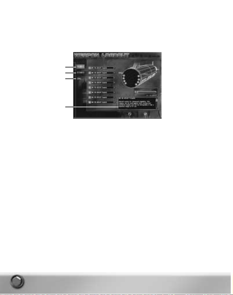
WEAPON LOADOUT
Depending on your mission tasking you may need to alter your default loadout. If you are tasked to
hunt down and destroy an enemy submarine, you don’t want your tubes full of land attack missiles
and your racks full of anti-ship missiles.The time to change your loadout is before you get
underway.From the Weapons Loadout screen you can change the weapons loaded in the tubes,
change the number and type of stored weapons, and adjust the loadout of your countermeasures.
The weapons available for each sub class vary but the method for changing the loadout is basically
the same in each controllable submarine.The 688(I) class has an additional loadout screen to
accommodate the vertical launch tubes and the Akula classes have an extra screen for their
external tubes.
Whenever an item is selected in the drop-down list information about the selected item appears in
the information window.
To change the loadout in torpedo and VLS tubes:
1.
In the Mission Brief screen click
WEAPON LOADOUT
.The Tubes loadout screen appears.The
current loadout is represented by numbered, colored dots on a wire frame representation of the
ship’s hull.The numbers represent the tube number.The name of the weapon loaded in each
tube is seen in the drop-down list associated with each tube number.The color of a dot on the
wire frame coincides with the color assigned to represent each specific weapon.
2.
Click the arrow in a weapon drop-down list associated with a specific tube and select a different
weapon from the list to change the weapon loaded in that tube.
3.
Change loadout in Stores or CMs (countermeasures) before clicking OK.
■ In the 688(I) class,click
VLS
to alter the loadout in the ships Vertical Launch System (VLS)
tubes. Changes are made as described above.
■ In the Akula Classes,click
INNER TUBES
to change the loadout in the ship’s internal tubes.Click
OUTER TUBES
to change the loadout in the six tubes that are external to the pressure hull.
Changes are made as described in the steps above.
4.
Click OKto implement all of your changes and return to the Mission Brief screen.
5.
Click
CANCEL
to ignore any changes you make on any of the screens and return to the Mission
Brief screen.
24
Information Window
Tubes
Stores
Countermeasures
Page 25

To change the number and type of weapons stowed:
1.
Click
STORES
.A screen showing the type of weapons that can be carried on your sub is
displayed along with the number of weapons for each type currently stowed in the racks and in
the tubes. Only rack stowed weapons can be changed on the Stores screen.
2.
Click the right or left facing arrows associated with each weapon type to increase or decrease
the number of that weapon stowed.
3.
At the bottom of the Rack Stowed column a tally showing the number of weapons currently
stowed is followed by the total number of weapons it is possible to stow on your submarine. For
example if you are commanding a Seawolf class sub the numbers 48/52 means that there are
currently 48 weapons stowed and it is possible to stow 52. You can add four more weapons
before you reach your maximum.
4.
Make the desired changes to all loadout screens before clicking OK.
• Click
OK
to implement your changes and return to the Mission Brief screen.
• Click
CANCEL
to ignore any changes you made on any of the screens and return to the Mission
Brief screen.
To change the countermeasure loadout:
1.
Click
CMS
at the left of the screen.A screen displaying the current countermeasure loadout is
seen.The number of internal and external countermeasure tubes may vary depending on which
sub class you are commanding.
2.
Click the arrow in a countermeasure drop-down list associated with a specific countermeasure
tube and select a different type of countermeasure from the list to change the countermeasure
loaded in that tube.
3.
Make the desired changes to all loadout screens before clicking OK.
■ Click
OK
to implement your changes and return to the Mission Brief screen.
■ Click
CANCEL
to ignore any changes on any of the screens and return to the Mission Brief
screen.
NOTE:
The changed loadout is attached to your player name and becomes your sub’s default
loadout for all subsequent missions you play with that player name.
CAMPAIGN
Click the Campaign button to access the Campaign Selection Screen. From here you choose a side,
select the submarine to command and go head to head with the best the enemy has to offer in the
selected campaign mission.
THE STAGE WAS SET
The Russian Defense Minister: “A nuclear submarine fleet is the future of the armed forces. The
number of tanks and guns will be reduced, as well as the infantry, but a modern navy is a totally
different thing.”
CNO CONGRESSIONAL TESTIMONY:House National Security Committee Testimony, 1996 Defense
budget, February 22, 1995:
“...The Russians today have six submarines at sea that are quieter than the 688(I)s, our best
submarine. ... This is the first time since we put Nautilus to sea that they have had submarines a t
sea quieter than ours.As you know,quieting is everything in submarine warfare.”
But even as these words were spoken, the Soviet era had given way, and the submarine warriors
had a few years to rest on their laurels.
25
Page 26

RUSSIA RESURGENT
A new government has come to power in Russia with a promise of restoring the country to
international prominence as a world superpower.Militar y units are being rebuilt through increased
training, mass production of existing weapons, and research and development to provide new
capabilities.
The leading edge of this activity is the Russian submarine force, which has suffered the least
decline since the end of the cold war. Submarines are engaged in opera tions to gain intelligence
about U.S. forces and to ensure U.S. submarines are not able to observe Russian exercises.The
Russians are especially keen to enshroud the development of a new anti-air warfare missile.
The U.S. leadership in the Department of Defense, the State Department and the intelligence
agencies has initiated actions to monitor Russian capabilities and determine their intentions.
Submarines are critical assets for covertly gaining the required information.
Peacetime Rules of Engagement are still in force but as the Russians increase preparations, the
encounters between the two countries become more frequent and the possibility of hostilities
intensifies.The risk of an undeclared war beneath the surface increases with every encounter.
To combat the new capabilities of the Russian Improved Akula-I and Akula-II submarines,the U.S.
fleet commissioned the Seawolf class submarine in the late 90s.While quieter and more capable
than any nuclear submarine at sea, construction of the class was canceled for all but three vessels.
Only two Seawolf class submarines are currently deployed.The 688(I) class remains the backbone
of the U.S. submarine fleet.
Tensions are rising,and the premier submarines of the two navies must be the first instruments of
national policy.However, a submarine is merely an extension of the wit, crea tivity and will to win of
the Commanding Officer.If you have the skill, knowledge and character to command the world’s
elite submarines, step up to the challenge of Sub Command.
CAMPAIGN ORGANIZATION
The campaign is divided into fourteen missions.You can elect to play all thirteen missions of the
campaign as the commander of a Russian Akula class,a U.S. 688(I) or Seawolf class submarine.
With minor exceptions (noted in the descriptions), the same missions are present in all three
campaigns; only your perspective and goals and the capabilities of the submarine you command
are changed. In each mission, one submarine has an offensive role and the other has a defensive
role.The opposing force may have several submarines, but you have no friendly submarines.
Regardless of the ship chosen, you have the same required missions, although the order is
somewhat different.
In Sub Command, failure to achieve specific goals need not result in the necessity to replay the
mission.There will, however, be mission-relevant consequences in future missions depending on
whether or not you complete important goals as you go along.
The early missions require support of naval exercises in home waters and missions in enemy
coastal waters for observation of enemy naval operations and insertion of Special Forces. Both
submarine forces focus on an upcoming test of the new Russian anti-air missile in the early
missions. If the Russians can deny U.S. forces’ knowledge of the characteristics of this weapon,
then the Russian Northern Fleet will be much more effective when the battle is eventually joined.
26
Page 27

To begin the Campaign:
1.
From the Main menu,click
CAMPAIGN
.The Campaign screen appears.
2.
In the Campaign Selection Window click the name of the sub class you want to command for the
campaign:
Seawolf, 688(I)
or
Akula
. Mission names appear in the Mission Selection window.
• To view saved campaign missions click
Saved Missions
.A list of saved campaign missions
appears in the Mission Selection window.
3.
Select the first (or next available) mission in Mission Selection window.A description appears in
the Mission Description window.A tasking overview a ppears in the Tasking window.
4.
In each Campaign only one sub is available to pilot.Your sub’s name is listed in the Specific Sub
Selection window.
Note:To proceed to the next mission, you must successfully complete all the mission’s critical
goals. Critical and non-critical goals are listed in the Mission Status screen during gameplay.
Press
º
during gameplay to access the Mission Status screen or select Mission Status
from the System menu.
5.
Click OKto receive the Mission Briefing or click
CANCEL
to return to the Main menu.
6.
The Mission Briefing is several pages long. Press
r
(default hot key) to move to the next
page.
7.
At the completion of the briefing the Mission Brief screen appears listing your tasking and
offering you a chance to change your weapon loadout.
8.
Click OKto start the mission or click
CANCEL
to return to the Campaign screen.
MULTIPLAYER
Up to eight players can link up via Internet or a local network to create alliances and engage in
combat against human opponents or computer AI.For in-depth information, see Multiplayer on
p.153.
Online gameplay for Sub Command will be available only through August 31,2002 subject to
online terms of use and all features may not be available at the time of purchase. Please check
online at www.ea.com for more information and terms of use.
27
Campaign Selection Window
Mission Selection Window
Mission Description
Specific Sub Selector
Controllable Sub Selector
Tasking Overview
Page 28

MISSION EDITOR
Custom build single or multiplayer missions anywhere in the world. Make your missions as simple
or complex as you desire and include random events,groups and opponents so that the game
plays differently each time it is played.You can place one controllable submarine or several in your
scenario and play the game from different perspectives. Opponents and allies can be created from
the navies of sixteen different countries. For in-depth information, see Mission Editor on p. 161.
PLAYER’S LOG
Sub Command maintains a log for all player names you create.The log displays every mission
attempted by your current player name and the results of each are displayed when you select the
name of a specific mission.
Missions are grouped by category.
1.
At the left of the screen click the desired text to select the type of missions you want to view.A
list of all mission titles of that type undertaken by your current persona is displayed. It may be
necessary to scroll down to see all mission titles. Multiplayer mission results are viewed with the
Single mission results.
2.
Click a mission’s title to see the results of that mission.The information displayed is the same as
that displayed on the Mission Debrief screen at the conclusion of that mission. Slightly different
information appears depending on the Mission Type.
3. BACK TO GAME LISTING
at the bottom of the mission information to return to the list of missions.
You may need to scroll to view this text.
4.
Click OKto return to the Main menu.
28
Select Mission Type
Player Name
Click Mission Title to
view results
Page 29

OPTIONS
Selecting Options from the Main menu displays the Options menu.The Game Options page
displays by default.The text buttons at the left of the screen indicate the type of options that are
available. Click the name of the Options page you wish to view. A green box around the text button
indicates the selected options page.
A check mark in a box associated with an option indicates the option is
ON
.
GAME:
Set Game and map control options.The following options are available:
Show Dead Platforms:
When ON, all platforms that are 100% destroyed display in their actual
locations on the Nav map and their actual identity is displayed in 3D View.Should the contact be
killed by a platform other than Ownship, the contact symbol displays on the Nav map whether you
have detected it or not.
If you have detected the contact, the contact’s symbol remains on the map moving at the course
and speed designated in the TMA solution even after the actual ship or object is destroyed.This
can result in seeing two symbols and two 3D models for the same contact when this option is on.
For example,assume you have a contact designated S01. You have a TMA solution on S01 that
places it on bearing 235 at a range of 4000 yds but the contact is actually on bearing 239 at a
range of 5000 yds.Additionally,you ha ve classified S01 as a Krivak class frigate when it is actually
a fishing boat.When you click S01 on the Nav map the 3D model of a Krivak appears in 3D view.
Now suppose that you fire a torpedo at S01 using your TMA solution. Because your solution is
close to the actual location of the contact the torpedo picks up the actual contact and destroys it. If
you are attached to the torpedo you will see it go right through your TMA solution in 3D because it
is not in the actual location of the contact.The torpedo proceeds on to the actual location of the
contact and kills it.A symbol for the contact immediately appears at the actual location of the
platform on the Nav map and the model of the dead fishing boat appears in the 3D View if you
select the symbol.Your S01 solution symbol and the Krivak model remain on the map until you go
to the TMA station,select S01 and drop it.
If Show Dead Platforms is OFF, you never see in 3D what you ha ve killed. Based on the sound of
explosions and the loss of a signal on a given bearing you may assume that you have killed
something. If you want to know for sure what you have killed without turning on this fea ture, go to
the Mission Status screen and scroll down to the Kills section.
Show Truth:
When ON, symbols for all objects in the mission display on the Nav map whether you
have detected them or not.When a ‘truth’ contact is selected on the map accurate information
29
Click to select Option Type
Selected Option Page
Page 30

about the contact is seen in the Data Display Indicator and in the 3D view.The information in the
DDI has a different format than that seen when Show Truth is OFF.
When ON no Contact IDs are seen in the TMA or Fire Control Drop-down lists.You can only engage
Truth contacts from the Nav map using the Contact menu’s Engage With command or by shooting
a Snapshot at the contact from the Fire Control Target Display.
Truth is OFF by default and must be enabled here or by using the keyboard command or the Nav
Map menu.The default keyboard command is shown.
• Press
v+q+T
to toggle the display of truth on the Navigation Map.
• From the Nav Map menu select Layers>Show Truth. Select Layers>Hide Truth to turn truth OFF
again.
NOTE:
A host in a multiplayer game can turn OFF the Show Truth capability so no players in the
game can use it.
Show Link Data:
When ON, friendly or allied contacts appear on the map as blue symbols of the
correct platform type. Since this information is provided from your link to other ships and satellites,
they are designated as Link reports and have an
L
designation on the Nav and Fire Control maps.
Clicking on an
L
contact on the map displays information in the DDI, in the 3D view and the
location of the platform that is accurate as of the last Link report. Link data is reported on a time
delay so the locations may not be exact but they are the locations with a high level of confidence.
Link information is updated on the map as long as the option is ON.
If the Show Link Data option is ON when you leave a mission, it is also ON a t the start of the next
mission.
This option can also be set as follows:
• Press
q+v+A
to toggle the display of Link Data for allied platforms and land sites.
• From the Nav Map menu select Layers>Show/Hide Link Data.
NOTE: L
contacts do not display in the TMA
Select
drop-down list. Some land sites are designated
during mission design as Auto Detect.A land site so designated is always visible and also
has an
L
designation. It remains visible even if Hide Link Data is selected.L and Lcontacts
do appear in the Fire Control Target list.
Fire Control Quick Launch:
When ON the time it takes to unload and load weapons and
countermeasures is reduced as follows:
■ Weapon unload/load time drops from 16 – 18 minutes (depending on the sub) to approximately
35 seconds.
■ Weapon load time drops from 8 – 9 minutes (depending on the sub) to 20 seconds.
■ Countermeasure unload/load time drops from nearly 6 minutes to 14 seconds.
■ Countermeasure load time drops from 3 minutes to 8 seconds.
Enable Tool Tips:
When ON the name of the screen, button name or function and in some cases
additional information displays when the cursor is held over game labels, buttons and entry fields.
3D:
Set screen resolution and 3D effects and testing options. Select Disable 3D to completely
disable 3D in a mission.
CREW:
Activate or deactivate Auto Crewmen.When ON, Auto Crewmen perform specific game tasks
as follows:
Radar Auto Crew:
When ON, Radar Auto Crewman marks and updates all Radar contacts as long as
the Radar is on.
TMA Auto Crew:
When ON,TMA Auto Crewman merges contacts,performs TMA assessment,and
enters Firing Solutions for all designated contacts.
30
Page 31

NOTE:
When the TMA Auto Crewman is ON you cannot adjust solutions at the TMA Station If you
attempt to move the TMA Ruler or make entries in the Trial Solution Fields,your TMA Auto
Crewman moves them back to the settings he entered.
Sonar Auto Crew:
When ON, the Sonar Auto Crewman marks contacts in Narrowband sonar and
assigns trackers. (Trackers appear in both Narrowband and Broadband Displays) He then
commences classifying the contact in Narrowband. Once classified the contact’s symbol on the Nav
map changes shape to reflect the classification determined by the Sonar Auto Crewman.You must
still assign an alliance to the contact from the Contact menu’s Designate Type/Alliance>Alliance
option. See Ship Station/Na vigation Sta tion/Contact Menu on p. 45.
NOTE:
When Sonar Auto Crewman is ON you can still assign trackers and mark contacts.In some
cases you may be quicker than he is.You can also move the Narrowband Cursor to
designate the search area for the
Sonar Auto Crewman
.
Fire Control Auto Crew:
When ON, the Fire Control Auto Crewman enters presets appropriate for the
contact.
NOTE:
Be aware that if you designate a contact as a surface ship when it is really a submarine, the
Fire Control Auto Crewman enters presets appropriate for a surface ship.He uses your
classification and the existing TMA firing solution to determine appropriate presets,even if
your classification and firing solution are wrong.
For more detailed information on Auto Crew functionality, see Ship Stations/Auto Crewmen on p.
146.
■ Setting Novice Defaults turns ON all Auto Crew options.
■ Setting Advanced Defaults turns OFF all Auto Crew options.
SOUND:
Enable voice commands as well as in-game sound and music options.A list of available
English voice commands is found in VoiceCommands.doc located on the Sub Command CD.
CONTROLS:
Displays hot key assignments for the 2D Map, 3D View and General game functions.
Hot key assignments can be changed here. See Options/Changing Hot Key Assignments below.
MULTIPLAYER:
These options are only available to the host in a multiplayer game. Options you set
here are enabled when you host a Multiplayer game. If you join a Multiplayer game any options you
set here are disabled.When you host you can also set these options from the Game Room. See
Multiplayer/Multiplayer Options on p. 157.
CHANGING HOT KEY ASSIGNMENTS
To change hot key assignments from the Options>Controls pages:
1.
Double-click the text of the option you want to change.The option is highlighted and the text
changes color.
2.
Press the desired new key or key combination.An alert message appears if that key or key
combination is already assigned to another command and displays the name of the command
currently assigned the key(s) you pressed.
■ Click
YES
to swap the two key assignments.
■ Click
NO
to maintain the current hot key settings.
3.
Click
OK
at the bottom of the Options menu to accept all changes or click
CANCEL
to ignore all
changes and retain your previous settings.
31
Page 32

SAVING OPTIONS CHANGES AND RESTORING DEFAULTS
To save options changes:
• Click OKto apply all changes made on any page. The Options menu closes.
To exit the Options menu without enabling any changes:
• Click
CANCEL
.The Options menu closes.
To set setting to the default options:
1.
Click
DEFAULTS
on each page to set that type of options to the default settings shipped with the
game. Each option type has a separate Defaults button. Some Options have Novice and
Advanced Settings. See Novice and Advanced Defaults below.
2.
There are three pages of Controls options. Click the check box at the top of the screen to select
that page of Control options. Clicking Defaults on any of those three pa ges resets the default
options on all three pages.
NOVICE AND ADVANCED DEFAULTS
Some types of options are turned on or off at game startup depending on whether you selected
Novice or Advanced settings during game installation.
• To switch from one setting to the other or to restore the original settings if you have altered them
select Novice Defaults or Advanced Defaults as desired from each page that contains those
options.
• If a page has only one Defaults button, the default options are the same for both novice and
advanced players.
NOTE:
This manual assumes
Advanced Defaults
are selected. If you have selected Novice settings,
your game experience is slightly different than described in this manual. For information on
the settings enabled for the Novice player,read about Game and Crew Options above and
see Ship Stations/Navigation/Playing From The Nav Station on p.50.
■
Advanced Defaults
turns OFF all Game page options except Enable Tool Tips.No Crew options
are enabled.
■
Novice Defaults
turns ON these Game page options: Show Link Data, Show Dead Platforms, and
Fire Control Quick Launch.All Crew Options are enabled.
USNI REFERENCE
Data from the U.S. Naval Institute (USNI) was used as the reference for the information in the
online USNI browser,and for the performance parameters used in the game databases. An y
deviations from USNI data for gameplay purposes are annotated in the browser entries.
USING THE BROWSER
To access Reference Information from the Main menu:
1.
Click
USNI REFERENCE
on the Main menu.The Information Browser opens.
2.
Click the desired nation and platform name or the desired weapon type and the weapon name
about which you want to learn more.The browser shows the text entry by default.
3.
Click
TEXT,PHOTO
or 3Dat the left to view the designated type of entry.
4.
Press lto page through the text, photo or 3D entries of a given type for the selected country
or weapon type.
32
Page 33

To manipulate the 3D object in the browser:
• Press
SPACEBAR
or any arrow key to stop the rotation of the 3D object.
• Press
S
to start the object rotating again.
v+ =
Zooms in on the selected object or last camera position if nothing is selected on
the 2D Map.
v+ -
: Zooms out on the selected object or last camera position if nothing is selected
in the 2D Map.
v+ i
: Brings the camera above the object giving you a bird’s eye view.
v+ k
: Brings the camera under the object giving you a view of the bottom of the
object.
v+ j
: Moves the camera counterclockwise around the object.
v+ l
: Moves the camera clockwise around the object.
5.
Click the house (home) icon to return to the table of contents.
6.
Click OKto return to the Main menu.
To display the browser from any screen during gameplay:
• Press
F11
The browser opens.
or
• Press
s
then click
USNI REFERENCE
from the System Menu.
• Click
OK
to close the browser and return to the game.
PLATFORM-SPECIFIC INFORMATION
You can quickly access information on a specific platform in the game or in the Mission Editor.
During Gameplay:
1.
Select the contact on the Nav map then press a+ I.
The USNI Browser opens to the entry for the selected platform. Be aware that the browser provides
information on the platform as classified by you. If you select a contact you have classified as a
Kirov,the browser entr y for Kirov is displayed, even if the contact is really a Slava.
NOTE:
If Show Truth is ON, the browser displays the correct entr y for a selected contact.
2.
Click OKto return to the game.
33
Click to select country name
Click to select weapon type
Click to select a specific entry
Show Table of Contents
Page 34

In Mission Editor:
1.
Assign a country,class and name to the platform. Select the icon on the map and press
a+I
The browser opens to information on the selected platform.
2.
Click OKto return to the Mission Editor.
NOTE:
No USNI information is available on land buildings, civilian aircraft and sailing vessels. During
gameplay and in the Mission Editor,the browser’s Main menu displays if you attempt to
access platform-specific information about a contact that has no browser entry.
EXIT
To exit the Main menu:
• Click EXIT.A Sub Command message box appears asking you to confirm that you want to leave
the game.
• Click
OK
to exit to Windows.
• Click
Cancel
to return to the Main menu.
SHIP STATIONS
There are seventeen stations plus the Task Bar on each controllable submarine.While the stations
on each controllable sub are different in appearance, their basic functionality is quite similar.This
section describes what happens at each station. When basic functionality is the same, directions
for performing the station’s functions are presented with any slight differences between the subs
noted under each step.A description of the screen parts and button names for each submarine
class follows the list of directions.
When the stations appear or function quite differently,steps for using a station’s functions are
included separately by submarine class.
NOTE:
The Improved Akula-I and the Akula-II submarine stations look and function identically within
the game. Both of these classes are referred to as simply ‘Akula’ in this manual.
GENERAL INFORMATION
SELECTED OPTIONS
On each class of submarine,color is used to designate a selected state for buttons and menu
options.
■
Seawolf:
Non-selected buttons and options are orange. Selected buttons and options are green.
■
688(I):
Non-selected buttons and options are green. Selected buttons and options are orange.
■
Akula:
Non-selected buttons and options are red. Selected buttons and options are white.
SYSTEM MENU
The System Menu is available on every submarine and from any ship station by pressing
s
during gameplay or by selecting System menu from the Nav Map menu. (Right-click the Nav map
surface to display the Nav Map menu.)
34
Page 35

The following options are available:
Resume:
Select this option to leave the System menu and resume gameplay.
Options:
Displays the Options menu.
USNI Reference:
Displays the USNI Browser.
Mission Status:
Displays the Mission Status screen giving you access to your captain name,
mission name, score, elapsed time,your mission goals and a list of
platforms you have destroyed up to this point in the game.
Save:
Displays the Save Dialog then returns you to the game.
Save and Exit:
Displays the Save Dialog then exits the mission.
End Mission:
Exits the mission without providing an opportunity to save the mission.
SEAWOLF BUTTON MATRIX
The Seawolf class utilizes a button matrix on many of its stations.
• Click any button that contains both text and a down arrow to display a panel with additional
options related to the clicked button.
• Click
BACK
(up-arrow) to return to the previous matrix panel.
• Click any button that contains only text (no arrow) to perform the described function.
NOTE:
In the Button Matrix a selected function is green.
MANUAL DESCRIPTIONS
It is possible to set Game Options that allow you to view the true location and identity of all
contacts, only Allied contacts and/or dead platforms on the Nav map and 3D. Except as noted,the
directions and descriptions in this manual assume that all Game Options with the exception of
Enable Tool Tips are OFF. See Main Menu/Options/Game on p. 29.
TASK BAR
The Task Bar appears at the bottom of all stations on all three classes of controllable subs.Task
Bar functionality is identical between the submarines and there are only slight cosmetic differences
from sub to sub.The Seawolf Task Bar is shown here. Each designated section is described belo w.
35
Stations Menu
Orders Menu
History Display
Maneuver Shortcuts and Game Readouts
Page 36

STATIONS MENU
Clicking the Stations menu button displays the pop-up Stations menu.The menu contains icon
buttons representing the major ship stations.The buttons are described below. Hold your cursor
over a button to display the name of the station. Each ship station is described in full later in this
section of the manual.
• Click a specific button to move to that station.
The Stations menu icons are defined below along with their default keyboard shortcuts.
ORDERS MENU
Certain basic orders can be given from any ship station using the pop-up Orders menu on the Task
Bar.Click the button to display the available menu options.
FIRE TUBE:
This option appears both here and on Ownship menu only when a target is assigned to a specific
tube at the Fire Control Station.
•
Tube Number: Weapon Name/Target ID:
Select a tube number to fire the weapon in the tube at
the designated target.
NOTE:
This menu option is always visible if a UUV is loaded in a tube. UUVs do not require a target
assignment so you need only fire the tube to launch it. See Special Operations and
Procedures/Deploying UUVs on p.149.
36
Ship Control (¡)
Sonar Suite (
™
)
Radar (
£
)
Radio Room/ESM (
¢
)
TMA (
∞
)
Fire Control Suite (
§
)
Navigation (
¶
)
Periscope/Stadimeter (
•
)
Page 37

NAVIGATE
Set Depth
Surface:
Orders your sub to the surface.
Go to PD:
Orders your sub to Periscope Depth.
Go Shallow:
Orders your ship to 100 feet/30 meters.
Go Deep:
Orders your ship to 800 feet/244 meters. Beware! If you are not in water
that deep, you will slam your ship into the bottom of the body of water.
Change Speed
All Ahead Flank:
Orders ship speed to the top speed possible for the sub you are
commanding.
All Ahead Full:
Orders ship speed to 14 kts less than the top speed possible for the sub you
are commanding.
Ahead Standard:
Orders ship speed to 15 kts.
Ahead 2/3:
Orders ship speed to 10 kts.
Ahead 1/3:
Orders ship speed to 5 kts.
All Stop:
Orders ship to a full stop.
Back 1/3:
Orders ship speed to 5 kts in a reverse direction.
Back 2/3:
Orders ship speed to 8 kts in a reverse direction.
All Back Full:
Orders ship speed to 4 kts less than the top reverse speed possible for the
sub you are commanding.
All Back Emergency:
Orders ship speed to the top reverse speed possible for the sub you are
commanding.
MASTS AND ANTENNAS
These menu options appear as long as the mast is still functioning.
Raise/Lower ESM:
Toggles the state of the ESM Mast (Electronic Support Measures).You must
be at the designated depth or shallower and at speeds of 10 kts or less if
the sail is submerged to avoid damaging the ESM Mast. For information on
ESM see Ship Stations/Radio Room/ESM Station on p.131.
SEAWOLF:70 ft (PD); 688(i) 65 ft; AKULA 16 Meters (PD)
Raise/Lower Radio:
Toggles the state of the Radio Mast.You must be at periscope depth or
shallower and at speeds of 10 kts or less if your sail is submerged to avoid
damaging the Radio Mast. For information on the Radio Room see Ship Ship
Stations/Radio Room/ESM Station on p.131.
Raise/Lower Periscope:
Toggles the state of the Periscope. Raising the Periscope at a speed greater
than 10 kts damages the mast if your sail is submerged. See Ship
Stations/Periscope and Stadimeter Stations on p.136.
Raise/Lower Radar:
Toggles the state of the Radar mast.You must be at the designated depth or
shallower and at a speed of 8 kts or less if your sail is submerged to avoid damaging the Radar
Mast. See Ship Stations/Radar Sta tion on p. 129.
SEAWOLF:70 ft; 688(i) 61 ft; AKULA 115 Meters
Lower All:
Quickly lowers all masts and antennas.
37
Page 38

COUNTERMEASURES
This menu and its options appear as long as Ownship has countermeasures of this type available.
Only internal countermeasure tubes can be reloaded. If you have two internal countermeasure
tubes containing one each of Active and Passive Decoys,all four of these options a ppear.This is to
permit you to select the depth for the CM. If you Select Active Deep, both Active options disappear
since you now have only one CM loaded, a Passive Decoy. Once you launch the Passive Decoy no
countermeasure options are available from this menu and you must reload the tubes from the Fire
Control station.
If you have two Active Decoys loaded,only the two Active options display in this menu until you
have fired both countermeasures.Then no options appear until you reload CMs.
Active Decoy Deep:
Selecting this option launches an active decoy to a default depth of 800 ft/244
meters.
Active Decoy Shallow:
Selecting this option launches an active decoy to a default depth of 100
ft/30 meters.
Passive Decoy Deep:
Selecting this option launches a passive decoy to a default depth of 800
ft/244 meters.
Passive Decoy Shallow:
Selecting this option launches a passive decoy to a default depth of 100
NOTE:
The Seawolf has eight external countermeasure tubes.The CMs in the external tubes are
fired first when this option is selected.You can set countermeasures to a specific depth from
the Seawolf’s Fire Control Countermeasure Launch Panel.See Seawolf Fire Control Suite/
Seawolf Countermeasure Launch Panel on p. 120.
HISTORY DISPLAY
The center portion of the Task Bar allows you to select and view a running log, or history, of three
types of messages.
HISTORY SELECTION BUTTONS
A lit button indicates the currently selected History type. If you ha ve a message in any other
window,that window’s selection button flashes until you select the button and view the message in
that history window.
Crew Report History:
(Blue Circle) Displays the crew reports in the History Window.Crew reports
include but are not limited to the crew responses to your orders to change depth and speed.Some
tasks performed by the Auto Crew are shown here but are not reported audibly.
Radio History:
(Green Square) Displays all radio messages in the History window.Your original
tasking brief is found at the top of the history.Messages related to game status also appear here.
Latitude and longitude coordinates are easily accessible while viewing the Nav map by opening the
Radio History window and scrolling to the coordinates.
Chat History:
(Yellow Triangle) During multiplayer games click this button to view new messages
and review your chat history in the History window.
38
History Selection Buttons
Crew Reports
Radio Messages
Multiplayer Chat
History Window
Expand/Contract Window
Page 39

HISTORY WINDOW
The History window displays a complete history of all crew reports, briefs and all radio traffic,or
multiplayer chat messages. Select one of the Histor y Selection Buttons to the left of the window to
select which type of message history is displayed. The last two lines of the currently selected
history type display in the History window when it is not expanded. When the History windo w is
expanded, a scroll bar appears if the length of the message histor y exceeds the window opening.
Expand/Contract History Window
• Click the up-arrow to display the entire History window.You may have to scroll to view the entire
contents of a given history within the window.
• Click the down-arrow or the map surface to close the History window.
MANEUVER SHORTCUTS AND GAME READOUTS
This area of the Task Bar provides game and Ownship information and provides shortcuts for
ordering ship maneuvers.
DEPTH, COURSE AND SPEED
Use the Maneuver Shortcuts to change your depth, course and speed from any ship station. Depth
is shown in feet on the U.S. subs and in meters on the Akulas.
To issue a maneuver command:
• Point the cursor at a digit and click to cycle forward through the digits.
• Right-click a digit to cycle backward.
■
Seawolf:
Orange numbers indicate the current depth, course and speed. Digits are green while
you click them.
■
688(I):
Green numbers indicate the current depth, course and speed. Digits are orange while
you click them.
■
Akula:
Red numbers indicate current depth, course and speed. Digits are white while you click
them.
To see the depth,course or speed you ordered while the ship is still maneuvering, visit the Ship
Control Station or check the crew report in the History window.
KEEL
This readout allows you to keep track of the water depth under your keel.This is handy when
operating in shallow littoral waters.
39
Change Depth
Depth Under Keel
Change Course
Change Speed
Game Time/Pause Indicator
Game Speed
Page 40

GAME TIME/PAUSE INDICATOR
The Time field displays the time of day in the mission based on a 24-hour clock.If the game
scenario starts at 1:00 p.m., the time field shows 13:00 and increments from that time.
When the game is paused, the word
Paused
replaces the time digits.
• Press
P
to pause the game.
• Press
P
again to resume gameplay.
TIME COMPRESSION SCALE
When playing time is a factor or you need to transit for long distances, it is helpful to speed up
gameplay.In addition to real time, Sub Command supports four levels of time compression.The
time scale displays in the far right of the Task Bar.A stack of colored bars represents time
compression.
■ At real time, a single green bar is displayed.
■ At twice real time a lime (yellow/green) bar appears above the green bar.
■ At four times real time a yellow bar is added to the stack.
■ At six times real time an orange bar is added.
■ At up to eight times real time (depending on system capability) a red bar appears a t the top of
the stack.
• Press
+
on the number pad or left click on the time scale to toggle through all scales in an
increasing order of compression. Real time follows 8x in this rotation.
• Press
-
on the number pad or right-click on the time scale to toggle through all scales in a
decreasing order of compression. In this rotation 8x follows real time.
NOTE:
Time compression is not available in Multiplayer missions.
NAVIGATION STATION
Each mission begins at the Navigation Station, sometimes called simply Nav. The Navigation
Station consists of three areas: the 2D Map, the Data Display Indicator and the 3D View.If you so
choose, you can play much of the game from Nav as described later in this section. It is from here
that you view all contacts you have marked or designated with your sensors and set the
classification for the contacts you classified in the Narrowband Sonar, ESM or Periscope/Stadimeter
stations.
40
2D Map
Contact Symbols
Data Display Indicator (DDI)
3D View
Line of Bearing (LOB)
Ownship Symbol
Page 41

2D MAP
The 2D Map represents the 600 by 600 (n.m.) battle space. Not all of the battle space is visible.
You must scroll up or down to view the hidden portions.Be aware that some contacts could be
hidden behind the 3D window.
• Use the arrow keys to scroll the map in the direction indicated by the arrow.
• Press
v
and click a map location to zoom in on that spot.
• Press
v
and right-click the map to zoom out.
• Press
s
then select Options from the System Menu.
The lower left corner of the map provides the following information:
■
Latitude and Longitude:
At the location of the cursor.
■
Depth/Height:
Displays the depth of the water or the altitude of the land at the location of the
cursor.
■
Range scale:
In nautical miles and yards.
■
Ice Coverage:
As a percentage when ice is present at that map location.
MAP MENU
Right-clicking on the 2D Map surface displays the Map menu.The Map menu contains a variety of
tools that allow you to customize your map interface by adding markers and labels and filtering
which symbols, text or other map aids display there. The Map menu items are described belo w.
Filters:
Use filters to toggle the display of specific map objects.
ALLIANCES
Hide Threats:
Hide/show all contacts designated Threat.
Hide Allieds:
Hide/show all contacts designated Allied.
Hide Neutrals:
Hide/show all contacts designated Neutral.
Hide Unknowns:
Hide/show all contacts designated Unknown.
NOTE:
If Show Truth is ON and contacts you expect to see do not appear on the Nav map check to
see if you have inadvertently turned off the display of one of the alliances.
Hide/Show Tags:
Displays or hides the names of all platforms and weapons next to the appropriate
symbol.The name that displays is your classification for that contact, which may or may not be
correct.
Hide/Show Tracks:
Hides or displays the alphanumeric contact IDs.
Hide/Show Marks:
Hides or displays all markers you have placed on the map.
Hide/Show Area Circles:
Hides or displays any Area Circles you have placed on the map.
Hide/Show Lines:
Hides or displays any lines you have placed on the map.
Hide/Show Labels:
Hides or displays any labels you have placed on the map.
LAYERS
Show Link Data:
Displays the locations of all friendly platforms whether you have detected them or
not.This information is provided by various link connections with satellites and other ships on
Ownside. Since this data is provided on a time delay, the locations may not be exact but they are
the locations with a high level of confidence.These contacts have
L
designations.Lcontacts
appear on the map but are not selectable in TMA or Fire Control.Select this option again to turn off
the display of Link data.
41
Page 42

NOTE:
Some land-based Lcontacts are visible even if this option is turned off.These land sites
were designated as ‘automatically detectable’ when the mission was created.
Hide/Show Truth:
Displays the correct location and identity of all platforms and objects in the
game. See Main Menu/Option/Game/Show Truth on p. 29.
Drawing tools
Add Mark:
Select this option then click the map to place a marker. Double-click the marker to add
a label to the marker.
Sub Command TIP: You can also press e while your cursor is over the 2D Map to
place a marker at the location of the cursor.
Add Area Circle:
Select this option, click the map to place the center of the circle, then drag the
cursor to define the radius of the circle.Click again when the circle is the desired size. Doubleclicking on the center of the circle displays a dialog allowing you to change the radius of the circle
and create a label. Click the digits to increment the value. Right-click to decrease the value.
• To delete an area circle click the center point of the circle and press
y
.
Add Range Circle:
Range circles can be added to Ownship and any platform symbol. Select this
option then position the cursor over Ownship or the desired contact.The cursor changes shape
when it is over a valid contact. Click the contact and drag the circle to the desired size. Click a gain
to place the circle.
• To delete a range circle,right-click the platform to display the Contact menu then select Remove
Range Circle.
NAV MAP CONTACTS
When each contact is designated or marked it is given an alphanumeric contact ID that is used on
the Nav map,TMA station, Fire Control and other stations in the game.
The first letter of the contact ID represents the source of the data:
S
for Sonar (passive, active, UUV)
R
for Radar
V
for visual/periscope
E
for ESM
M
for contacts merged in TMA
L
for Link
• Click a contact symbol to select the contact.
A contact first appears on the Nav map as a symbol at the end of a LOB. The default length of the
LOB depends on which sensor has detected it.The symbol in use is usually the symbol for
Unknown (platform type)/Unknown (alliance). See Contact Symbols below.The contact’s ID number
accompanies the symbol.The color and default lengths for lines of bearing are shown here.
Passive Sonar contacts:
White, Blue or Purple LOB 10 n.m. long
Active Sonar contacts:
Green LOB at the range reported by the sensor.
ESM contacts:
Red LOB 20 n.m. long
Visual contacts:
Red LOB 10 n.m. long
Radar contacts:
Yellow LOB at the range reported by the sensor.
UUV passive sonar contacts:
White LOB 10 n.m. from the UUV.
UUV active sonar contacts:
Green LOB at the range from the UUV reported by the sensor.
42
Page 43

NOTE:
Merged contacts and link contacts have no LOBs.
A contact with a TMA solution appears on the map as a symbol at the location designated by the
TMA solution you have entered.The line of bearing disappears.
The symbol for a contact changes shape once it is classified. Classification is the process of
determining the class of a contact and its alliance.It is important to know that the contact is
hostile before launching weapons.
You assign a classification to a contact from the Contact menu’s Classify Contact option using
information you collect from narrowband sonar,ESM or the stadimeter.These sta tions are covered
individually later in this chapter.(For information on the Contact menu options see Ship
Stations/Navigation Station/Contact Menu on p. 45.)
When the game begins only your Ownship symbol is visible on the map.You must use your sensors
(usually sonar) to detect contacts, then create TMA solutions for them.The symbol for
Unknown/Unknown is used for a contact until it has been classified.
See Ship’s Stations/Sonar Stations on p. 58 for information on contact detection. Ship’s
Stations/Target Motion Analysis (TMA) Station on p.96 provides information on how to create a
TMA solution.
NOTE:
If you have selected Novice settings at install or in the Options menu your experience may be
different. Blue link contacts may appear and your Auto Crew marks contacts and performs TMA
assessments for you so contacts other than Ownship may appear on the Nav map.
CONTACT SYMBOLS
Contacts are displayed on the 2D Map as symbols.These symbols use shape and color to convey a
platform’s type and its alliance.
Colors
Sub Command uses the following colors to denote side alliances.
COLOR: ALLIANCE:
Blue
Ownside/Friendly
Orange
Allied
Red
Hostile
Yellow
Unknown
Green
Neutral
When a platform is destroyed, its symbol turns a shade of gray depending on its alliance.
Destroyed platforms belonging to Ownside appear as a light shade of gray while all other destroyed
platforms display as a dark shade of gray.The ability to see the symbols of destroyed platforms is
on by default. Dead platforms appear on the 2D Map whether you ha ve detected them or not. You
can turn OFF this feature on the Options>Game page by deselecting the See Dead Platforms
option.
Alliances
Sub Command uses the following definitions when assigning alliances to contacts in missions.
FRIENDLY
Contacts that are either Ownside or friendly to Ownside.Allies are
designated Friendly.
HOSTILE
All platforms, weapons, and land-based sites identified as belonging to
countries hostile to Ownside.
UNKNOWN
Any contact not yet identified as Friendly,Hostile, Neutral or a Biologic.
NEUTRAL
All platforms allied with neither Friendly or Hostile sides.
43
Page 44

The Symbols
The shape of a symbol provides important information concerning the contact’s type.Some ships,
submarines, airplanes and missiles have a different symbol shape depending on its alliance. Some
symbols are the same shape regardless of alliance. In those cases, you must rely on the color of
the symbol to determine the alliance of the contact. See Colors above.
SYMBOL OBJECT SYMBOL OBJECT
Ownship Surface Ship, Neutral
Unknown/Unknown Missile, Ownside/ Friendly
(Neither platform type nor
its alliance is known)
Submarine, Ownside/Friendly Missile, Hostile, Unknown
Submarine, Hostile Torpedo
Submarine, Unknown Helicopter
Submarine, Neutral Mine
Aircraft, Ownside/ Friendly Land-based Object
Aircraft, Hostile Downed Pilot
Aircraft, Unknown Explosion
Aircraft, Neutral SEAL Team
Surface Ship, UUV (Unmanned
Ownside/Friendly Underwater Vehicle)
Surface Ship, Hostile DSRV (Deep Submergence
Rescue Vehicle)
Surface Ship, Unknown Biologic
44
Page 45

CONTACT MENU
Once a contact appears on the map, select it by clicking on its symbol. Right-clicking on a contact
displays the Contact menu. From this menu you can assign a classification to the contact as well
as attack it or find information about it as described below.
Engage With:
Tube X:
Select a tube and its currently loaded weapon to fire at this contact. (If you want to change
a weapon loaded in a tube, you must visit the Fire Control Station.) The firing solution currently
entered for this contact in TMA is used to target the weapon.Be aware that your solution is rarely
accurate early in the tracking process. If no TMA solution has yet been entered, the weapon fires
down the line of bearing using the default presets for the selected weapon.
NOTE:
An Unknown/Unknown contact does not have an Engage With option in its Contact menu.
Until you designate the contact as surface or subsurface the game doesn’t know which type
of weapons to place in the Engage With menu.
Deploy Special Forces:
This menu only appears in the Engage With menu of surface ships and land
buildings and only under these conditions:
■ Ownship has Special Forces aboard.
■ Ownship is traveling at periscope depth or less and at 3 kts or less.
For more information see Special Operations and Procedures /Deploying and Recovering Special
Forces on p. 148.
Designate Type/Alliance:
If you are relatively sure of this contact’s platform type or alliance you can
assign it here without specifying a ship class.The contact’s map symbol changes shape and color
according to your selections. 3D view displays a wire-frame model of a generic ship, plane or
submarine bounded by a colored box denoting the alliance type. See Ship Stations/Navigation
Station/Contact Symbols/Colors on p.43.A bar representing level of confidence is also visible in
3D.You can also assign a level of confidence from this menu option.
NOTE:
This menu option does not display if Show Truth is on. See Main Menu/Option/Game/Show
Truthon p. 29.)
Platform Type:
Assign a platform type to the contact: Surface, Submarine,Air, Biologic or Unknown.
The contact’s symbol changes shape to that of the designated platform type.
Alliance:
Assign an alliance to the contact: Friendly,Hostile, Neutral or Unknown.The contact’s symbol
changes color to that of the designated alliance. See Contact Symbols /Colors on p. 43.
Confidence:
Assign a level denoting how confident you are in the accuracy of your classification.
Select Low,Medium or High.
Classify Contact:
Selecting this option displays the Classification Dialog.This option does not
display if Show Truth is on. See Main Menu/Option/Game/Show Truth on p. 29.
Once you have a good idea of a contact’s class use the Classification Dialog to assign that
classification to the contact and designate a level of confidence in your assessment.
1.
From the class list,select the desired class name.To narrow your search, use the Sort By Type
drop-down to eliminate all platform types but the type for which you want to search:
Submarines, Surface ships, Aircraft or Biologics. (If you have classified a contact in Narrowband
Sonar,the class name that was visible on the screen when you left that station is highlighted in
the classification window when you select a contact on the Nav map.)
2.
Click the desired class name to assign that class name to the contact.Information and a photo
of the selected class appear on the right side of the dialog box.
45
Page 46

3.
Click LOW,MED or HIGH to indicate your level of confidence in this classification. The
classification name and your level of confidence appear in the DDI whenever the contact is
selected on the map.
4
.Assign an Alliance to the contact.Click ALLIED,THREAT, NEUTRAL or UNKNOWN.
5.
Click OKto accept the classification.Click
CANCEL
to return to the game and negate your changes.
6.
When you click OK,your classification is applied and the contact’s symbol appears as that of the
specified platform type.
7.
When you click a classified contact in the Nav map,a 3D model of that platform class appears in the
3D view.The 3D view displays whatever class you have assigned, whether you are correct or not!
Show History:
Displays a dot trail on the map indicating the movement of this contact as you have
tracked it with your sensors.
Platform Reference:
Displays the USNI Reference entry for the selected contact as classified by
you. If you classify the contact as a Kirov,the entry for Kirov appears, even if the contact is really a
cruise ship. If you have not classified a contact, no informa tion appears.
NOTE:
USNI data provides information on military ships and aircraft. No information is available on
buildings, civilian aircraft and sailing vessels.
Spec Ops
Deploy DSRV:
This menu option only appears on a submarine’s Contact menu and only if these
conditions are met:
■ The DSRV is loaded on Ownship.
■ Ownship is moving at 3 kts or less and is at or below periscope depth.
When this option is selected the DSRV launches and proceeds to the selected submarine. Be aware
that the DSRV will attempt to mate with whichever sub you have selected whether or not this is the
sub you have been tasked to rescue. Make sure you are not trying to rescue a hostile sub.
Remove Range Circle:
If a range circle has been added to the contact’s symbol,this option
becomes available. Select this option to remove the range circle.
OWNSHIP MENU
Right-clicking on the Ownship symbol displays a set of options specific to Ownship.
Fire Tube:
This option only appears here (and on the Orders menu) when you have assigned a
target to a tube and defined presets for the weapon from the Fire Control Station or if there is a
46
Class List
Sort By Type
Information on class selected in
Class List (if available)
Photo of class selected in
Class List
Designate Level of Confidence
Designate Alliance
Contact ID for contact being
classified
Page 47

UUV loaded in a tube.When this option appears, a second level menu is available tha t lists any
tube that has a weapon assigned and displays the assigned target.
Tube (Number): (Weapon) (Target):
Select the desired tube number to fire that tube’s weapon at the
target ID shown.
Navigate
Set Waypoints:
Select this option to add waypoints to Ownship on the Nav map.With each click a
new waypoint is added. Press
u
or right-click to complete the process.
Placing Ownship waypoints automatically activates your Auto-Helmsman.He follows the waypoints
until you order a change in course. See Playing from the Nav Station/Ownship Waypoints on p 50.
• Double-click a waypoint to specify a specific lat/long.
Change Course:
Select this option then click the Nav map to order a course in that direction.
Set Depth:
See the Ship Stations/Task Bar/Orders Menuon p. 36 for a full description of these
options.
Change Speed:
See the Ship Stations/Task Bar/Orders Menuon p. 36 for a full description of these
options.
Masts and Antennas:
Ownship’s masts and antennas can be raised and lowered using this menu’s
options. For a full description of these options see Ship Stations/Task Bar/Orders Menu on p. 36.
Show History:
Select this option to display movement history for Ownship.A dot is placed every
two minutes showing the location of the platform at that point in time.
Platform Reference:
Displays the USNI Reference for Ownship.
Remove Range Circle:
Only appears if a range circle has been added to Ownship’s symbol.Select
this option to remove the range circle.
Hide/Show Waypoints:
Only appears if you have added waypoints to Ownship.
Remove Waypoints:
Only appears if you have added waypoints to Ownship. Select this option to
remove waypoints.
Resume Waypoint Follow:
Only appears if you have added waypoints to Ownship and have ordered
Ownship to a different course (i.e., Ownship is not currently following the waypoints on its own.)
Select this option to return Ownship to the assigned waypoints. See Playing from the Nav
Station/Ownship Waypoints on p. 50.
DATA DISPLAY INDICATOR (DDI)
The Data Display Indicator (DDI) provides information about a selected contact. When you enter the
game, only the Ownship symbol is visible on the 2D Map. If you select the Ownship symbol,
information relative to Ownship appears in the Data Display area in the upper left corner of the
Nav.
When you or your TMA Auto Crewman have entered a solution for a contact,the solution fields
contain data when that contact’s symbol is selected.The solution section contains the current firing
solution that is used when targeting the selected contact.This is set when you enter a solution
from the TMA station.(See Ship Stations/Target Motion Analyses (TMA) Station on p. 96.)
Bear in mind that the information in the DDI is only as accurate as your classification and TMA
solution. It represents your current ‘best guess’ about the selected contact.
When a contact is selected on the 2D Nav map the following information is available:
Contact:
Displays the contact ID number: S01, R01,E01,V01 etc.
Alliance:
Displays presumed alliance: Friendly,Hostile, Neutral as designated by you.
47
Page 48

Platform:
Displays the presumed platform type: Surface, Submarine,Air or Biologic as designated
by you or your Sonar Auto Crewman.
Class:
Displays the class as designated by you or your Sonar Auto Crewman.
Confidence:
Displays the current level of confidence in the classification as designated by you or
your auto crewman. Defaults to
LOW
.
Solution:
The information in the three rows of the solution section represents the last solution
entered in TMA station by you or your TMA Auto Crewman.These fields are blank until a solution
has been entered in TMA.
Bearing:
Displays the bearing to the contact as designated in the TMA Solution.
Range:
Displays the current estimate of the range to the contact.
Course:
Displays the estimated course of the contact.
Speed:
Displays the estimated speed of the contact.
Bearing Error:
The average of the bearing error that is displayed in the TMA dot stack.
Bearing Rate:
Represents the change in bearing of the contact over time.A high bearing rate could
indicate that the contact is close.The contact could also be farther away but moving very rapidly.
An
L
or R(for left and right) precedes the bearing rate number.If looking down the line of bearing,
an
L
means that the contact is moving to the left,Rmeans that it is moving to the right.
Age:
The amount of time that has passed since you last updated the firing solution.
Source(s):
Displays sensor input for this contact.
NOTE:
When Show Truth is on, the DDI displays the selected contact’s actual name, class, course,
speed and percentage damage.
3D VIEW
3D view is on by default in the small retractable window in the upper right of the Navigation
Station.The position of the 3D View and the 2D Map can be switched to provide a larger 3D view.
• Press
v+ M
to swap the position of the 2D Map and the 3D view.
• Or click the swap window button next to the up arrow in the upper right corner of the Navigation
Station.
3D VIEW CONTROLS
Use these keys to adjust the 3D view.
48
Data Display Indicator (DDI)
Page 49

• Click the 3D model and drag the mouse to rotate the angle of your view.
• Press
v
and left-click and drag or use the mouse wheel to zoom in and out.
• Press
q
+ left-click and drag left or right to pan.
• Press
v+ =
to zoom in on the selected object or last camera position if nothing is
selected on the 2D Map.
• Press
v+ -
: to zoom out on the selected object or last camera position if nothing is
selected in the 2D Map.
• Press
v+ i
: to bring the camera above the object giving you a bird’s eye view.
• Press
v+ k
: to bring the camera under the object giving you a view of the bottom of
the object.
• Press
v+ j
: to move the camera counterclockwise around the object.
• Press
v+ l
: to move the camera clockwise around the object.
DISABLING AND HIDING 3D
As mentioned previously,the purists may prefer to disable 3D completely.This is done on the
Options>3D page.You can also hide 3D from within the game without disabling it completely.
• Press
v+ A
to hide the small window.Since 2D and 3D can be swapped, whichever
view is in the small window is hidden.
• Or click the up arrow in the upper right of the Navigation Station to hide the small window.The
arrow changes to a down arrow.
• Click the small down arrow to display the small window again.
Remember that until a contact is classified, clicking on its symbol displays a transparent bubble
floating on the water in the 3D view.Until a specific classification has been assigned to a contact,
no specific 3D model can be displayed. If you have designated a type and alliance to a contact
using the Contact menu’s Designate Type/Alliance option,a generic model of the platform type is
seen in the 3D View when you select the contact.Box corners of the color representing the
assigned alliance surround the model.
A bar indicating level of confidence is also present in the 3D view.Green indicates low confidence,
yellow indicates medium level of confidence, and red indicates high confidence in your
classification of the selected model.
Remember,unless the Show Truth cheat is on,the loca tion of the 3D object coincides with the
location of your TMA solution and is only as accurate as your TMA assessment! See Main
Menu/Options/Game/Show Truth on p. 29.
49
Swap 2d/3d view
Close/Open small window view
Page 50

PLAYING FROM THE NAV STATION
With your Auto Crew activated,it is possible to play much of the game from the Navigation Station.
Using a combination of voice commands, and the Orders, Contact and Ownship menus you can
navigate, track, classify and attack enemy ships,launch Special Forces, and read your message
traffic.You still need to go to the Periscope Station to see the outside world or conduct an ESM
search.You must go to the Fire Control Station if you want to reload a tube, enter specific wea pon
presets or wire guide a torpedo.
ATTACKING SEA TARGETS FROM NAV
To select a sea contact,a contact symbol must be present on the Nav map. When ON, your Sonar
Auto Crewman marks and classifies contacts.The TMA Auto Crew creates a firing solution for
contacts within range of your submarine.
TO LAUNCH WEAPONS AGAINST SURFACE AND SUBMARINE TARGETS
Using the Contact menu:
1.
Right-click the contact symbol to display the Contact menu.
2.
Select Engage With and specific tube number.The name of the weapon loaded in the tube
appears after the tube number.
■ If the Fire Control Auto Crewman is ON,presets are entered for the weapon based on the firing
solution information and the platform classification.
■ If the Fire Control Auto Crewman is not ON,weapons fired from the Nav Sta tion use the default
weapon settings.
■ The Engage With menu does not appear for Unknown/Unknown contacts displaying a line of
bearing. For contacts with a LOB and a classification, the Engage With menu displays weapons
appropriate for the type of platform specified.
Using Orders or Ownship Menu:
Fire Tube:
If you have assigned a target to a tube from the Fire Control Station, this menu option is
available on these two menus.
• Select the desired tube to fire the weapon.
NOTE:
An Unknown/Unknown contact does not have an Engage With option in its Contact menu.
Until you designate the contact as surface or subsurface the game doesn’t know which type
of weapons to place in the Engage With menu.
LAUNCHING LAND ATTACK MISSILES FROM NAV
Land contacts with an Ldesignation can be targeted from the Nav with a land attack missile.
1.
Right-click the land contact to display the Contact menu.
2.
Select Engage With.Only Land Attack Missiles are available from the menu. If no Land Attack
Missiles are loaded in any of your tubes there will not be an Engage With option.
3.
Select the desired tube.The weapon launch sequence is initiated and cannot be stopped.
OWNSHIP WAYPOINTS
Whether you play the game from the Navigation Station or spend your time in Sonar and TMA, it is
nice to give your helmsman some standing orders and let him steer the ship. Placing waypoints on
the map automatically activates the Auto Helmsman. See Ship’s Stations/Auto Crewmen on p. 146
for information on how to utilize this crewman.
50
Page 51

Place waypoints through a tricky strait, around islands or set them to take you toward a specific
destination.
To place a waypoint on the map:
1.
Press for select Add Waypoint from the Ownship menu.
2.
Click the map to place a waypoint.
3.
Continue to click the map until the desired waypoints have been placed.
4.
Right-click the map or press uto stop the process.
To add a single waypoint:
1.
Click the Ownship symbol.
2.
Press
v+ f
then click the map.
■ If no other waypoints exist, a single waypoint is placed from Ownship.
■ If other waypoints already exist, the additional waypoint is added after the last existing
waypoint.
Some Restrictions
■ Waypoints cannot be added or moved over land or water too shallow for a submarine.
■ Waypoints cannot be added or moved in such a way as the direct path to the previous or next
waypoint crosses land or water too shallow for a submarine.
VOICE COMMANDS
There are a variety of voice commands available during gameplay if you installed the speech
recognition software when you installed Sub Command.Voice commands behave similarly to their
keyboard counterparts and can only be used where a keyboard command is appropriate (e.g., they
are ignored when dialogs are visible).Voice commands are only recognized during gameplay but
not on the Options menu when accessed during gameplay.
You can train your speech engine by visiting the speech control panel accessed via the Speech
icon in the Windows 98,Windows 2000, or Windows ME control panel.You can also improve the
accuracy of the speech engine by adjusting the accuracy vs.performance slider in the speech
control panel.
NOTE:
The speech recognition software is not compatible with Windows 95.If you attempt to install
the game on a Windows 95 platform,the option to install the speech recognition software is
not seen.
NOTE:
The document Voice Commands.doc resides on the Sub Command CD and contains a list of
voice commands recognized by the game.
To utilize voice commands in the game:
1.
Select Options>Sound.
2.
Under the Speech heading select Enabled and, if desired, Always On. Always On is only a vailable
when Enabled is checked.
NOTE:
Both options are grayed if you do not have a speech engine installed.
When Enabled only is selected on the Options>Sound page:
• Press and hold the speech key while issuing a valid voice commands. By default the speech key
is SPACEBAR.
■ When the designated speech key is pressed during gameplay, voice recognition is listening and
the speech engine interprets anything you say.When this key is released, voice recognition is
not listening and it ignores anything you say.
51
Page 52

When Always On is selected on the Options>Sound page:
• Issue a valid voice command as desired at any point during gameplay.
■ When the Always On option is checked, the designa ted speech key is ignored and the speech
engine is always listening to what you say.
SHIP CONTROL
Ship Control is the hub of operations on a submarine. From here the Captain and the Officer of the
Deck oversee all the ship’s movements and activities.In Sub Command the ship’s speed,course
and depth can be altered from the Task Bar or by using voice or menu commands. Because of
these options, you need only visit Ship Control for specific evolutions that are performed
infrequently.
SHIP CONTROL TASKS
Each sub’s Ship Control Station is covered separately later in this section.The main tasks and
maneuvers conducted from the Ship Control Station are described here.
Stream or retrieve the towed array:
The most common task performed in Ship Control is to stream
the towed array,one of your sub’s most important sonar sensors. From here you can deploy the
selected array completely or partially,and retrieve the array if you anticipate maneuvers tha t could
cut it or cause it to drag on the bottom. Backing up cuts the towed array.
Sub Command Tip: When you start a mission check to see if the array is deployed.
If it is not, streaming the array should be the first thing you do. The mission
designer determines if the array is alr eady str eamed when the mission starts.
Emergency Surface the Ship:
From Ship Control you can also quickly surface your ship in an
emergency situation. During a procedure called an Emergency Main Ballast Tank Blow, or simply
Emergency Blow,high-pressure air is blo wn into the ballast tanks causing the ship to quickly rise
to the surface. How quickly you ascend depends on the amount of air available in your air banks.
Charge the Air Banks:
High-pressure air is needed to launch weapons and to surface the ship in an
emergency.Keep a close eye on the amount of air in your high-pressure air banks. Each wea pon
launched depletes your supply of high-pressure air.A charge of at least 50% is required to
successfully launch weapons from your torpedo tubes.An Emergency Blow procedure can
completely drain the banks resulting in the inability to launch weapons or emergency surface
again.
NOTE:
You can increase the high-pressure charge by only 10 percent while submerged.
Ventilation:
To fully charge your high-pressure air banks you must be at periscope depth and
ventilating.
Open/Close MBT (Main Ballast Tank) Vents:
If you are on the surface, opening the MBT vents floods
the tanks with water and allows the ship to dive.These vents must be closed after diving so air
can be pumped back into the tanks allowing the ship to surface again.When you are submerged
these vents should remain closed.Your crew automatically opens and closes the MBT vents when
you order the ship to dive or surface.As Captain, you don’t need to operate the MBT vent manually,
unless you want to.
52
Page 53

Change Course, Speed and Depth:
In Ship Control you can view the ordered as well as the actual
course, speed and depth. You can also change course and speed with a single click using the
Course Indicator and the Engine Order Telegraph.
The
Stern,Bow
and
Rudder
Indicators denote the positions of the respective control surfaces of the
ship. Zero represents a neutral setting for the bow/stern planes and the rudder.While your
Helmsman automatically controls all control surfaces whenever you order a depth or course
change, you can, if you like,manually set a rudder angle to change course.The ship will continue
to turn in the designated direction until you click zero on the Rudder Indicator or order a new
course using the Course Indicator or the Course shortcut.
The Seawolf’s trim display includes its Under Ice Display. 688(I)’s Ship Control contains its High
Frequency Sonar display.All three Ship Control Stations are described separately below.
SEAWOLF: SHIP CONTROL STATION
The Seawolf’s Ship Control Station is divided into two halves.The left half of the station provides
mostly information. Only the Course Indicator and the Rudder Indicator allo w for user interaction.
The right side contains the Trim and Ice Display,the Engine Order Telegraph and the controls for
the towed array and several ship systems.
Seawolf’s Ship Control Station employs the following conventions.
■ A green outline (or needle) and a finger cursor indicate that user input is possible in tha t
location.
■ Button text indicates what happens when you next click the button. Button text changes to
facilitate this feature.The only exception is the Emergency Blow button.That button text is
green when a blow is in progress and orange when it is
OFF
.The text does not change.
■ An orange outline around a box or feature indicates no user input is possible. The two
exceptions to this are the Rudder and Course Indicators.
■ Orange text on a button indicates that ship system is
OFF
or closed.
■ Green text indicates that the system is
ON
or functioning.
■ In the Engine Order Telegraph the selected button is green.
Seawolf’s Ship Control Station features are described briefly below.For more detailed information
about the use of these features and tasks performed at the Ship Control Station see Ship
Stations/Ship Control/Ship Control Tasks on p.52.
Ordered Depth:
Displays the last ordered depth.
53
Actual Course, Speed, Depth
and Sounding
High-Pressure Air Charge Level
Course Indicator
Rudder Indicator
Trim and Ice Display
Emergency Blow,Ventilation and
Bow Plane Controls
MBT Vents and High Pressure Air
Charge Controls
Towed Array Controls
Ordered Heading, Speed, Depth
Engine Order Telegraph
Page 54

Ordered Heading:
Displays the last ordered heading.
Ordered Speed:
Displays the last ordered speed.
The Engine Order Telegraph:
Click the desired button to order engine speed. Engine speeds
translate to ship speeds as defined in Ship Stations/Task Bar/Orders Menuon p. 36.. Flank
(maximum) speed for the Seawolf is 35 kts. Place the cursor over a button to display the engine
speed that button sets.
Heading:
Displays the sub’s actual heading.
Speed:
Displays the sub’s actual speed.
High-Pressure Air Bank:
Displays the current charge level in the high pressure air banks.
Depth:
Displays the sub’s actual depth.
Sounding:
Displays the depth of the water under your hull.
Course Indicator:
The orange needle indicates the ordered course.The green needle indicates the
current course.
• Click the desired bearing on the dial to order a new course heading.
Stern/Rudder/Bow Controls: Indicates the positions of the respective control surfaces of the ship.
Zero represents a neutral setting for the bow/stern planes and the rudder.
• Click the desired number in the Rudder Indicator to order a rudder change.
• Click zero in the Rudder Indicator or click in the Course Indicator to reset the rudder.
NOTE:
The ship will eventually turn in a circle if you do not reset the rudder to zero or order a
specific course.
Trim and Ice Display:
Displays the ship’s trim angle,shows the ice thickness profile when under
the ice, and displays the current depth beneath the hull when in shallow water.
■ The submarine profile adjusts in the display window to match the ship’s trim angle.
■ When operating under the ice a profile of the ice thickness above Ownship appears across the
top of the Trim Display.Any course change immediately redraws the profile. The Ice Thickness
Readout in the lower left of the display reports the thickness of the ice directly above the sail.
■ When the ship is traveling close to the bottom, an orange line indicates the depth directly under
the Ownship’s midpoint.
Emergency Blow:
Click this button to perform an emergency main ballast tank blow to quickly
surface the ship.The button text changes to green when a blow is in progress. Click the button
again to return to the
OFF
(orange) position.
Open MBT Vents/Close MBT Vents:
When you are surfaced, click Open MBT Vents to open the main
ballast tank vents and submerge your ship. Click Close MBT Vents to close the vents once
submerged.Your crew automatically opens and closes the vents when you order a dive. You can
open and close the vents yourself if you prefer.
Ventilate/Secure Ventilate:
Click Ventilate to commence ventilation.Click Secure Ventilate to stop
ventilating.Ventilation is only necessary when you need to recharge the high-pressure air banks.
(See Charge Air/Secure Air below.) The ship must be at or above periscope depth (69 ft.) to
ventilate.
Charge Air/Secure Air:
Click Charge Air to start the charging the High Pressure Air Banks.Click
Secure Charge to stop charging.You must be ventilating to fully charge the banks.
Rig in Bow Planes/Rig Out Bow Planes:
The ship’s bow planes are out by default.If you plan to
surface when under the ice, you should rig in (retract) the bow planes as a precaution against
damage. Click Rig in Bow Planes to retract the bow planes. Click Rig Out Bow Planes to return the
planes to their normal position.
54
Page 55

Towed Array Controls:
The Seawolf has two towed arrays the TB-29 and the TB-16.In general, the TB-29 is longer and
more sensitive than the TB-16,but the TB-16 remains effective at higher speeds.
■ Select the Starboard Towed Array to deploy the TB-29 array.
■ Select the Port Towed Array to deploy the TB-16.
The Seawolf’s Towed Array controls are shown below.
Starboard Towed Array/Port Towed Array:
Click the array name to toggle between the array
options.The visible name is the selected array.
• Click the right facing double arrows to deploy the selected towed array.
• Click the left facing double arrows to retrieve the selected array.
• Click the orange square to stop streaming or retrieving.
Scope:
The scope progress bar illustrates the length of the array currently deployed.
688(I): SHIP CONTROL STATION
688(I)’s Ship Control Station is shown below.
688(I)’s Ship Control Station features are described briefly below.For more detailed information
about tasks performed at this station see Ship Stations/Ship Controls/Ship Control Tasks on p. 52.
Trim Angle:
Indicates the trim angle of the ship measured from a horizontal axis.A positive trim
angle indicates the ship has a bow-up attitude. A negative trim angle indicates a bow-down
55
Selected Array
Deploy Towed Array
Retrieve Towed array Stop Scope (Array Progress Bar)
Trim Angle
HP Air
Towed Array Controls
Course Indicator
High Frequency Sonar
Ventilate
Rudder controls
Engine Order Telegraph
Emergency Blow
Speed
Depth
MBT Vents
Page 56

attitude.Your helmsman automatically controls the trim angle whenever you order a depth change.
HP Air:
This panel is used to monitor the current charge level in the high-pressure air banks and to
charge the banks when they are depleted.A charge of 50% is necessary for successful weapon
launches.The charge can be increased by only 10% when the ship is submerged.You must come
to Periscope Depth and ventilate while you charge to fully charge the banks.
• Click the unlit Charge button to commence charging your high-pressure air banks.The button is
lit when a charge is in progress.
• Click the lit Charge button to secure the charge.
Towed Array:
From this panel you select and deploy the desired towed sonar array (Port or
Starboard).The Scope field indicates the length or percentage of the array currently streamed.
• Click Port or Starboard to select that array to be streamed.Only one towed array can be
deployed at a time.
• Click Stream to deploy the array.
• To stop streaming or retrieving the array,click OFF.
• To retrieve the towed array,click Retrieve.
Course:
On this Course Indicator,the red needle indicates current course. The black needle
indicates ordered course
• To order a new course heading, click the desired bearing on the Course Indicator.
High Frequency Sonar:
The toggle switch activates the High Frequency Sonar System (HFSS),which
is used to detect small objects such as mines at short range.The High Frequency Sonar screen
shows the location of any object near your submarine’s bow.If an object is close enough, clicking
on it designates it as a sonar contact.
• Click
ON
to activate HFSS.
• To designate targets (such as mines), point the cursor at the object and click. A mark is placed
on the Nav map indicating each return received by the HF sonar.
Ventilate:
Ventilation is only necessary when you need to recharge the high-pressure air banks.
See HP Air above.The ship must be a t or above periscope depth (65 ft.) to ventilate.
• Click the unlit Ventilate button to commence ventilating.
• Click the lit Ventilate button to secure ventilating.
Stern/Bow/Rudder:
Your crew controls the bow and stern planes automatically when you change
depth but you can order a course change with the Rudder.
• Click the desired number in the Rudder Indicator to order a Rudder change.
• Click zero in the Rudder Indicator or click in the Course Indicator to reset the rudder.
NOTE:
The ship will eventually turn in a circle if you do not reset the rudder to zero or order a
specific course.
Engine:
This dial known as an Engine Order Telegraph orders engine speed. Engine speeds
translate to ship speeds as defined in Ship Stations/Task Bar/Orders Menuon p. 36. Flank
(maximum) speed for the 688(I) is 32 kts.
• Click the desired option to order that Engine Speed.
Emergency Blow Valve:
To surface your ship quickly in an emergency situation, click the red handle
to initiate the Emergence Blow procedure. Click again to secure the blo w. Remember to recharge
your air banks following an Emergency Blow.
Depth:
Actual and ordered depth is shown in feet.
• Right/left click the digits in the ordered field to order a new depth.
56
Page 57

Speed:
Actual and ordered speed is shown in kts.
• Right/left click the digits in the ordered field to order a new speed.
MBT Vents:
The main ballast tank vents are opened and closed automatically by your crew when
you order the ship to dive or surface. If you so choose, you can open and shut the vents manually.
• Click the unlit MBT Vents button to open the vents and submerge the ship.
• Click the lit MBT Vents button to close the vents.
AKULA: SHIP CONTROL
The Akula’s Ship Control Station and features are seen below.
Akula’s Ship Control Station features are described briefly below.For more detailed information of
tasks performed at this station see Ship Stations/Ship Control/Ship Control Tasks on p. 52.
Air Remaining:
Indicates the charge level in the high pressure air banks.
Air/Charge:
Initiates a charge of the high-pressure air banks.The charge can be increased by only
10% when the ship is submerged.You must ventilate to fully charge the banks.A minimum charge
level of 50% is necessary to successfully launch weapons.
• Click the Charge button to commence charging the air banks.A red light surrounding the button
indicates the charge is in progress. Click again to secure the charge.
Air/Vent:
(Ventilate) In order to fully charge the high-pressure air banks you must be at periscope
depth (16 meters/52 feet) and ventilating as well charging.
• Once at periscope depth, click the Vent button.The button is ringed in red when ventilating is in
progress. Click the Vent button again to secure ventilation.
Trim Angle:
Indicates the trim angle of the ship measured from a horizontal axis.A positive trim
angle indicates that the ship has a bow-up attitude. A negative trim angle indicates a bow-do wn
attitude.Your helmsman automatically controls the trim angle whenever you order a depth change.
Towed Array:
The Akula has one towed sonar array. Since it takes a while for the array to deplo y
and settle out it is important to deploy it early in the mission.The length of the array currently
deployed is displayed in the Length readout.The Akula’s towed array is fully deployed at 304
meters (approximately 1000 feet).
57
Air Remaining
HP Air charge Air/Vent Trim Angle Display
Towed Array Controls
MBT Vents
Course Indicator
Engine Order Telegraph
Depth
Speed
Planes
Sounding
Emergency Blow
Page 58

• Click Stream to deploy the towed array.
• To stop the streaming or retrieval of the array,click
OFF
.
• To retrieve the towed array,click Retrieve.
MBT Vents:
The main ballast tank vents are opened and closed automatically by your crew when
you order the ship to dive or surface. If you so choose, you can open and shut the vents manually.
• Click Open to open the vents and submerge the ship.
• Click Shut to close the vents.
Course:
On this Course Indicator,the orange needle indicates current course. The gray needle
indicates ordered course
• To order a new course heading, click the desired bearing on the Course dial.
Engine Order:
The Engine Order Telegraph orders engine speed. Engine speeds translate to ship
speeds as defined in Ship Stations/Task Bar/Orders Menuon p. 36. Flank (maximum) speed for the
Improved Akula-I is 28 kts.Flak Speed for the Akula-II is 30 kts.
• Click the desired option to order that Engine Speed.
Depth:
Actual and ordered depth is shown here in meters.
• Right/left click the digits in the ordered field to order a new depth.
Speed:
Actual and ordered speed is shown here in kts.
• Right/left click the digits in the Ordered field to order a new speed.
Planes:
Your crew controls the bow and stern planes automatically when you change depth but you
can order a course change with the Rudder.
• Click the desired number in the Rudder Indicator to order a Rudder change.The gray needle
indicates the ordered rudder position. Orange the actual position.
• Click
0
in the Rudder indicator or click in the Course indicator to reset the rudder.
NOTE:
The ship will eventually turn in a circle if you do not reset the rudder to zero or order a
specific course.
Sounding:
This readout shows the depth under the keel in meters.
Emergency Blow:
Blows high-pressure air into your ballast tanks to emergency surface your ship.
Remember to recharge your air banks following an Emergency Blow.
SONAR STATIONS
At the Sonar Stations you monitor the most important sensing equipment on board your submarine.
Six displays, each with a specific purpose, help detect,identify,track, and pinpoint contacts by
employing either active or passive sonar.The sonar suite is composed of these six displays:
Broadband, Narrowband, DEMON,Active, Active Intercept, and Sound Speed Profile (SSP).All six
stations are explained in this section. Information about UUV sensors and their use is covered in
Special Operations and Procedures/Deploying UUVs on p.149.
58
Page 59

SONAR STATION SELECTION BUTTONS
On all sonar stations six buttons are always visible and permit you to move from one sonar station
to another.The buttons contain the same icons regardless of which sub class you are
commanding. During gameplay place your cursor over a button to display the name of the station
reached by clicking the button.
Broadband Sonar Station
Narrowband Sonar Station
DEMON Sonar Station
Active Sonar Station
Active Intercept Sonar Station
Sound Speed Profile (SSP) Sonar Station
ABOUT SONAR
In order to understand the functions of the Sonar Suite it is important to understand a bit about
sonar.Sonar is used to detect both submarines and surface ships and it is your only sensor when
operating below periscope depth.There are two types of sonar: passive and active.
A passive sonar system consists of a set of hydrophones (sensors) that receive sounds produced
by other sources. Passive sonar can be used only to listen. Its major purpose is to detect and
classify other ships.Under optimal conditions, modern passive sonar can sense ships over several
nautical miles, thus allowing the submarine to detect potential targets or enemy ships long before
it comes into the range of their sensors. However,passive sonar has its limitations. With passive
sonar,the sonarman can only determine the direction, or bearing,of the sound source.The
distance to the other ship (range)–an important consideration when maneuvering into an attack
position and programming weapons–is initially unknown.
The same is not true of active sonar, which operates on the principal of echo ranging. An active
sonar system transmits a high-energy acoustic signal or “ping”.Objects in the area reflect the
sound, and the resulting echo is picked up by the submarine’s hydrophones.The la g in time
between the initial transmission and the returning echo reveals the target’s range with great
precision.
59
Page 60

The obvious advantage of active sonar is that it provides instant range information. The
disadvantage is that the active transmission can be received by enemy ships and used to locate
the transmitting submarine. Because of this risk active sonar is used only as a last resort for
determining a target’s range.
Target range can be determined with passive sonar,too. Using a process called Target Motion
Analysis (TMA), you can accurately determine another ship’s bearing, range, course,and speed (in
other words, its location in two dimensional space) simply by tracking the target with passive
sonar.See Ship Sta tions/Target Motion Analyses (TMA) Station on p. 96 for more informa tion.
SONAR ARRAYS
All controllable submarines in Sub Command have some form of bow,towed and hull arrays
although their capabilities differ.An array is an interconnected group of hydrophones or
transducers that focus either the transmission or reception of sound.Together the arrays provide
omnidirectional sonar detection capabilities; however,no array in itself provides full 360° detection.
This is because the ship itself masks a certain amount of the environment from the sensor.
Spherical/Cylindrical Bow Array
The spherical/cylindrical array in the bow can track broadband as well as narrowband contacts.
Passive detection ranges from approximately 750 Hz to 2.0 kHz. In active mode, the array
transmits and detects at a higher frequency range of approximately 1.5 kHz to 5.0 kHz.
The spherical/cylindrical array can process broadband signals.At higher speeds, there is some
degradation of performance because of flow noise caused by the water moving across the surface
of the array.The bow array is not as sensitive to low frequencies, so it’s not the array of choice for
narrowband contacts emitting only low frequencies.
Hull/Conformal Array
The hull/conformal array,also near the bow of the ship is a linear array tha t provides low speed
capability to detect low frequency narrowband contacts (50 Hz -to-1.0 kHz).As such, its primary
use is for classifying targets.
AN/BQG-5 Wide Aperture Array (WAA):
the WAA consists of three flank arrays on each side of the
SSN21 class submarines.The WAA can provide rapid passive localization (RAPLOC) for sonar
contacts within a 15 kyd range.
Towed Array
The towed linear array—pulled behind the submarine on a long tow cable so it won’t pick up the
submarine’s own machinery noise—is used for both broadband and narrowband detection and
tracking (10 Hz–1.0 kHz). It is used at low to medium speeds, and is optimized for lower
frequencies.All controllable submarines in Sub Command have at least one towed array.The
capabilities of the towed arrays vary from class to class.
The SSN21 carries these two different towed arrays, the AN/TB-16 and the AN/TB-29.The TB-16 is
a 3.5-inch diameter array,which is thicker than the thin line TB-29 array.The TB-16 will suffer less
self-noise than the TB-29 at a given speed,but the TB-29 will be more effective at the lower
frequencies.
60
Page 61

SONAR LIMITATIONS
The location of the sensor as well as physical conditions such as the propeller wash of your ship
can limit which sounds can reach your sensors.The towed array can not pick up contacts in front
of your submarine and the spherical array can not pick up contacts behind the ship.
The Spherical/Cylindrical Array detects contacts in the areas around Ownship as shown below.
The Hull/Conformal Array detects contacts in the areas around Ownship as shown below.
The Towed Array detects contacts around Ownship as shown below.
61
Page 62

BROADBAND SONAR
The Broadband Sonar Station displays input from the spherical/cylindrical bow,and towed arrays.
In the Akulas the data from the conformal array is also available in the Broadband Sonar Station.
These inputs are used to detect and track submarines and surface ships. Here trackers can be
assigned to contacts and they are given an alphanumeric Contact Designation or ID. Contact IDs for
all sonar contacts begin with the letter S.Trackers provide the TMA station with updates on the
contact’s bearing at specified time intervals.
NOTE:
UUV sonar contacts also have Sierra (S) designations, but their data is not reported in the
Sonar Suite. UUV data is available in TMA and on the Nav and Fire Control maps.
SEAWOLF AND 688(I): BROADBAND WATERFALL DISPLAYS
Both the 688I and Seawolf submarines utilize dual waterfall displays to track sonar information. In
the waterfall display,sonar informa tion ‘cascades’ down over time giving a sense of the contact’s
movement. Bearing is displayed on the horizontal axis with either north (000) or south (180) in the
center.Time is displayed on the vertical axis, with the most recent information at the top.
A thin line beneath the V indicator indicates the direction your submarine’s stern is pointing.A faint
orange (Seawolf) or green (688I) line represents a weak contact while a strong contact appears as
a brighter,thicker line. The speckled background represents background noise interference. The
amount of interference increases as background noise increases.
Both the upper and lower waterfall displays show broadband sonar data. It is a good idea to have
one display set on Short Time Average (1–60 seconds) and the other on Intermediate (0–30
minutes) or Long (0–2 hours).The longer the time averaging that is employed the better the sonar
detection processing. However,the longer the time averaging, the longer the time between contact
updates. Both the spherical sensor and the towed array pick up broadband data in the Sea wolf and
688(I).The information displayed depends on which sensor is selected.
62
Ownship Indicator
Contact
Tracker
Bearing Indicator
Page 63

AKULA: BROADBAND CIRCULAR SSAZ DISPLAY
The broadband display in the Akulas is circular and represents Sensor Strength versus Azimuth
(SSAZ).The SSAZ display consists of three concentric bands extending from an inner circle. Each
band represents data from a different Akula sensor.The innermost band, displays contacts
detected on the conformal array.The second, or middle band, displays towed array contacts while
the outermost band displays contacts on the cylindrical array.
NOTE:
The towed array must be deployed before any contacts can appear in the Towed Array band
on the SSAZ Display.
The 360-degree Bearing Indicator rims the outer edge of the Circular Display.A narrow speckled
ring near the inner edge of each band indicates background noise on that sensor.Contacts on the
arrays appear as spikes emerging from the background noise at a specific bearing and extending
toward outer edge of the band; the stronger the signal, the taller the spike.
Clicking inside a specific band selects that array.The outer edge of that band brightens and
enlarges slightly indicating that the band and the array it displays is selected and the name of the
selected array appears in the Array window just below the SSAZ display.
On the SSAZ Display,a thin line extending from the center to the outer edge represents Ownship.
The line ends with an arrow indicating the direction Ownship’s bow is pointing.
Each sensor display has its own cursor.A cursor appears as a short line extending into the array
from each array’s outer edge.Click inside the array to move the cursor to that loca tion on that
array’s bearing indicator or click the cursor and drag it to a new location.The cursor is used to
identify the contact you want to mark.
NOTE:
There are no numbers on the bearing Indicators for the inner arrays.You must refer to the
numbers on the outer edge of the display.
Ship speed greatly interferes with the ability of the Akula’s sensors to detect and display contacts.
Excessive speed results in the inability to detect any contacts at all. Only background noise is
visible and that appears as a thick, jagged band a t the outer edges of each array.
63
Ownship Indicator
Contacts
Tracker
Bearing Indicator
Cylindrical Array
Towed Array
Conformal Array
Cursors
Page 64

ASSIGNING TRACKERS
1.
Select the sonar array you want to view in the broadband display.
Seawolf:
• Click
SELECT ARRAY
.
• From the resulting button matrix click
SPHERE
or
TOWED
.
• Click
BACK
.
688(I):
• In the Selected Array panel click the desired button.The button at the bow of the submarine
graphic represents the sphere array.The button aft represents the towed array.
Akula:
• Click inside the desired circle to select that array.Outer: Cylindrical,Middle:Towed Array,Inner:
Conformal array.
2.
Click the desired contact line.
A vertical cursor appears on the bearing indicator.You can click
and drag this cursor along the bearing indicator.
Seawolf:
• Click an orange Contact line.
688(I):
• Click a green Contact line.
Akula:
• Click a spike extending toward the outer edge of the selected array.
3.
Click the appropriate button to designate the target and assign a tracker.
(If the signal is faint,
you may have to click more than once.)
Seawolf:
• Click
ASSIGN TRACKER
.
688(I):
• Click
DESIGNATE TARGET
.
Akula:
• Click
TRACK ASSIGN
.
64
Background noise
Page 65

■ A tracker letter is placed above the contact line on Seawolf and 688(I) or below the spike on
Akula. Four trackers are available for each sonar array.
A, B, C,and D:
Spherical/cylindrical contacts.
E, F,G, and H:
Hull/conformal contacts. (These trackers can only be assigned in Narrowband on the
Seawolf and 688(I) submarines. On the Akula they can be assigned in both broadband and
Narrowband.)
I, J, K,AND L:
Towed array contacts.
■ If the sphere/cylindrical array already has four contacts assigned to trackers (A-D) and you
designate a new contact, the oldest tracker is unassigned from its current contact and
reassigned to the new contact.This is also true for the hull and towed arrays.To unassign a
specific tracker,click on the letter and drag it into the Display and release it.
■ Each contact you designate is assigned a sequential Sierra number:S01, S02, S03,etc.The
Sierra number,also called a Contact ID or Track ID,and all available data on the contact are
automatically sent to TMA and the Nav map.
TOWED ARRAY CONTACTS
Unless the towed array is deployed, no contacts will appear in Display when tha t sensor is
selected.Towed array contacts do not appear immediately when you deploy the array. If the to wed
array is not already deployed at the beginning of the mission, you can stream it from the Ship
Control Station.
Because of the way the towed array processes signals, an ambiguous contact, a mirror image of
each true contact, appears on the display along with the true contact. If you have a contact at the
same bearing on your bow array,you can be fairly certain a contact a t the same or nearly the
same bearing on your towed array display is the contact’s true bearing.
If the contact is not visible on the bow array,changing the course of Ownship allo ws you to
determine which contact is the actual and which is its mirror image on the display.After you
maneuver,one contact remains at a consistent bearing and one appears to move in the display.
The contact’s true bearing is the contact that remains constant.
When numerous contacts are present or the contacts are close together, this process can be very
challenging!
NOTE:
Be aware that when you turn Ownship your towed array does not begin to turn until it
reaches the point in the ocean where the ship began its turn.As a result, Ownship appears
as a contact on the towed array during turns.
SEAWOLF:
BROADBAND STATION
65
Upper Waterfall Display
Lower Waterfall Display
Data Display
Button Matrix
Sonar Station Selection Buttons
Page 66

The Waterfall Display and the Sonar Station Selection buttons are described above.The Broadband
Data Display and the Button Matrix are described here.
Seawolf Broadband Data Display
Cursor,contact and tracker information is displayed here. (The cursor is the vertical line above the
bearing indicator in the waterfall display.Click the Bearing Indicator to move the cursor to that
point or click the cursor and drag it to move it along the Bearing Indicator.)
Crsr Brg:
Indicates the bearing at the location of the cursor or of the tracker when a tracker is
selected with the Tracker Review button.
Sensor:
Indicates which sensor is currently selected: Sphere or Towed.
Tracker:
Displays the tracker letter assigned to the selected contact.
Contact:
Displays the Contact ID assigned to the selected tracker or contact.
WAA RNG:
When the cursor is over a broadband contact and a WAA range can be determined for
that contact, the range to the contact displays in this field.
■ Seawolf’s Wide Aperture Arrays (WAA) can provide limited range information for contacts within
15,000 yds of Ownship if acoustic conditions in the area are favorable.
SNR:
Displays the Signal to Noise Ratio at the location of the cursor.SNR indica tes the strength of
the signal.
Seawolf Broadband Button Matrix
Display Center:
Displays button options for setting the center of the waterfall display to North (000
degrees) or South (180 degrees).
Select Array:
Displays button options for selecting which sensor data will be displayed in the
waterfall:Towed or Sphere.
Assign Tracker:
Clicking here assigns a tracker to the contact at the location of the cursor.
Tracker Review:
Displays contact information in the Data Display for each assigned tracker.
Repeated clicks cycles through all trackers.
RAP LOC:
Rapid Localization. Clicking this button sends any a vailable WAA range information on the
selected sonar contact to TMA.A tracker must be assigned to the contact. The range information
appears on the next TMA bearing line for the contact.
■ Seawolf’s Wide Aperture Arrays (WAA) can provide limited range information for contacts that
are within 15000 yards when conditions permit.
Audio:
Displays buttons to toggle the broadband audio on and off.When ON, the sound produced
by a broadband contact is audible when it is selected in the Broadband Display.
Time Scale Top:
Displays button options for setting the time average in the upper Waterfall Display:
Select STA,ITA, LTA (see below).
Time Scale Bottom:
Displays button options for setting the time interval in the bottom Waterfall
Display:
Select STA,ITA, LTA (see below).
■ STA = Short Time Average
■ ITA = Intermediate Time Average
■ LTA = Long Time Average
Sonar Selection Buttons:
Click the button of the sonar station you want to visit. Hold your cursor
over a button to display the name of the station it represents.
66
Page 67

688(I): BROADBAND STATION
688(I)’s Broadband Station is shown below.
Sonar Station Selection Buttons:
Click the icon button of the sonar station you want to visit. Hold
your cursor over a button to display the name of the station it represents.
Audio Toggle:
When ON a cursor placed on a sonar contact emits the sound produced by the
contact.When OFF no sound is emitted.
Center Display Toggle:
When North Centered is selected the waterfall display is centered at 000
degrees.When South Centered is selected the waterfall display is centered at 180 degrees.
Upper Waterfall Time Average:
Select the time average setting for the upper waterfall display.Click
the text of the word that describes the desired setting: Short, Intermediate or Long.
Track ID:
Displays the alphanumeric Track ID of the selected track.
Designate Target:
To place a tracker on a contact and assign a Track ID (Sierra number) click the
contact in the waterfall display then click Designate Target.The Sierra number (S01, S02, S03,etc.)
is assigned to the contact, and the sensor data is sent to TMA.
Tracker Review:
Click this button to cycle through all assigned trackers.The Track ID,also known
as the Sierra number or Contact ID, is displayed in the Track ID field.
Cursor Position:
Indicates the bearing at the location of the vertical cursor in the Bearing Indicator
section of the waterfall display or cursor location of the tracker when a tracker is selected with the
Tracker Review button.
Lower Waterfall Time Average:
Select the time average setting for the lower waterfall display. Click
the text of the word that describes the desired setting: Short, Intermediate or Long.
Select Array:
The two buttons represent the sphere sensor (in the bow) or the towed array (aft).
Click the desired button to display that sensor’s input in the waterfall display.
67
Sonar Station Selection Buttons
Audio Toggle
Center Display Toggle
Upper Waterfall Time Average
Track ID
Designate Target
Tracker Review
Lower Waterfall Time Average
Select Array
Page 68

AKULA: BROADBAND STATION
The interiors of both the Akula-I Improved and the Akula-II are the same in Sub Command.For
simplicity,both of these interfaces will be referred to as Akula in this manual.
The Akula Broadband Station buttons and fields are described below.
Broadband Display:
This Sound Signal versus Azimuth display (SSAZ) shows contacts from the
Akula’s cylindrical,towed and conformal arrays and allows for marking these contacts. See Sonar
Stations/Akulas: Circular SSAZ Display on p. 63 for a full description of this display followed by
directions for assigning contacts in this display.
Audio:
Toggles Contact Sound ON and OFF. When ON placing the cursor on a contact in the SSAZ
display emits only the sound generated by that contact. Defaults to ON.
Tracker:
Displays the tracker letter for a contact you select on the display if it has a tracker
assigned or for the contact selected when Cycle Contacts is clicked.
Cursor Bearing:
Displays the bearing at the selected cursor location or the bearing of a tracked
contact when Cycle Contacts is clicked.
Signal to Noise Ratio:
Displays the signal to noise ratio at the location of the cursor.
Cycle Contacts:
Click this button repeatedly to cycle through all assigned trackers in the selected
array.Information on the selected tracker displays a t the left of the screen in the Tracker, Cursor
Bearing and Signal to Noise fields as well as in the Track ID field below the SSAZ display.
Array:
Displays the name of the array selected in the SSAZ display.
Track ID:
Displays the Sierra number (Contact ID) of the the contact at the location of the cursor if it
has been assigned an ID or the ID of the tracker selected when Cycle Contacts is clicked.
Assign Track:
When the cursor is on a contact in the selected array,click this button to assign a
tracker to the contact and send all sonar information to TMA.
Sonar Station Selection Buttons:
Click the appropriate button to move to that Sonar Station. See
Sonar Station Selection Buttons on p.59.
68
SSAZ Display
Audio
Sonar Station Selection
Buttons
Tracker
Cursor Bearing
Signal to Noise Ratio of Contact
Cycle Contacts
Selected Array
Track ID
Track Assign
Page 69

NARROWBAND SONAR
Each ship class has a unique sound frequency signature.The Narrowband function is used to
classify sonar contacts by comparing the frequency signature of the selected contact against a
database of known frequency signatures.
Regardless of which sub you are commanding, the ship’s computer narrows your search by
presenting only those signatures that have similarities to the signature of the selected contact.
Each sub’s Narrowband Station is covered separately below.
SEAWOLF: NARROWBAND SONAR
Narrowband Search Display:
On the Narrowband Search Display signals from the selected array
display in an A-scan format.A contact’s signal displays as a spike at the bearing where it is
detected.The height of the spike represents signal strength. High peaks indicate strong signal
strength.
NOTE:
Ownship’s speed can affect your ability to detect contacts in Narrowband.When the entire
signal line is near the top of the display this indicates that background noise is very high.
This usually happens when your speed is over 5 kts for hull array contacts or over 15 kts for
towed array contacts. Decrease your speed to reduce water flow over the array.
69
Narrowband Search
Display
Narrowband
Waterfall Display
Ship Classification
Window
Narrowband Data
Display
Narrowband Button
Matrix
Sonar Station
Selection Buttons
Page 70

Narrowband Waterfall Display:
The Narrowband Waterfall Display separates a signal from the
bearing selected in the Narrowband Search Display into discrete frequencies.The horizontal axis
represents the range of frequencies and the vertical axis represents time in seconds.The frequency
range is adjustable using the frequency scale as described below.Vertical lines represent specific
frequencies in the sound signal emitted by the selected contact.Together all of the frequency lines
represent that contact’s sonar signature.
NOTE:
Straight lines indicate a consistent signal. Curved or wa vy vertical lines represent distortions
or variations in the signal.
Ship Classification Window:
This window displays the sound signature of the class or weapon
named in the Profile Selector.Click
DISPLAY SIGNATURE
in the Button Matrix to access the Profile
Selection Panel and the Profile Selector. See Display Signature in the Narro wband Button Matrix
section below.
Seawolf Narrowband Data Display
Frequency Scale:
Displays the frequency range currently viewed in the Narrowband Waterfall
Display and the Ship Classification Window.This range is selected using the Frequency Scale
button in the Narrowband Button Matrix.
Cursor Frequency:
Displays the precise frequency of the signal selected in the Narrowband
Waterfall Display.
• To select a signal, click the desired line in the Narrowband Waterfall display. The cursor moves to
that location in the Horizontal Frequency Display and the frequency at the cursor location
displays in this field.
Sensor:
Displays the name of the selected array.Use the Select Array button in the Button Matrix to
select a different sensor.
Cursor Bearing:
Displays the location of the cursor on the bearing indicator at the top of the
Narrowband Search Window.
Tracker:
Displays the assigned tracker letter of the selected contact when the Tracker Review
button is clicked on the Button Matrix.
Contact:
Displays the alphanumeric ID (contact ID) of the contact selected when the Tracker Review
button is clicked on the button Matrix.
70
Narrowband Search Display
Contact
Cursor
Narrowband Waterfall Display
Specific Frequencies
Tracker
Ship Classification Window
Sound Signature of ship selected
in the Profile Selection Panel
Page 71

SNR:
Signal to Noise Ratio.This field displays the SNR of the selected contact.A high number
indicates a strong signal.
Seawolf Narrowband Button Matrix
The Seawolf utilizes a button matrix on many ship stations. Buttons containing a down arrow
display a second panel providing options related to the button text. Buttons with no down arrows
perform the described function when clicked.Click Back to return to the previous matrix.
Display Center:
Displays a panel for setting the center of the Narrowband Search Window to either
North (000) or South (180).
Select Array:
Displays a panel for selecting which sensor’s signals are displayed in the Narrowband
Search window.(Sphere,Towed,Hull.)
NOTE:
The towed array must be deployed before any towed array signals can be detected. The
Towed Array is deployed in the Ship Control Station.
Tracker Assign:
Click to assign a tracker to the frequency line selected in the Narrowband Waterfall
Display.
NOTE:
If the signal is weak you may have to click more than once to designate the contact and
assign the tracker.You cannot assign a tracker while the game is paused.
Tracker Review:
Click this button to cycle through all trackers assigned in Narrowband.Information
on each tracker is viewed in the Data Display in the Cursor Frequency, Cursor Bearing, Tracker,
Contact, and SNR fields.
Frequency Scale:
Displays a panel for selecting one the following frequency ranges: 0 to 2000
(default), 1000, 500,300, 150 and 50.
Display Signature:
Displays the Profile Selection Panel.See below.
Profile Selection Panel:
Your ship’s computer queries its database and provides you with the ship classes and weapons
that have signatures which include the currently selected narrowband lines.The names of these
ship classes or weapons can be seen one at a time in the Profile Selector.The sound signature for
the class named in the Profile Selector displays in the Ship Classification Window.
To classify the contact:
1.
Select a contact in Narrowband search
2.
Click the previous or next buttons to cycle through the available profiles.
3.
Compare each ship’s signature in the Ship Classification window to the signature of the selected
contact in the Narrowband Waterfall display.
71
Back
Profile Selection Panel
Click to select previous profile
Profile Selector
Click to select next profile
Page 72

4.
Click the Back button then the Frequency Scale button.Select a range to compare the
frequencies in that range.
5.
When you find the profile that most closely matches the selected contact’s sound signature,
leave that name selected in the Profile Selector,and make a mental note of the contact’s
bearing.
■ When you leave Narrowband Sonar the class name showing in the profile window is sent to the
Contact menu’s Classify Contact dialog available on the Nav map.Move to the Nav map to
complete the classification process.
On the Nav Map
1.
Select the symbol of the contact that you just identified in Narrowband.
NOTE:
If the contact that you have classified in Narrowband has not yet been assigned a Contact ID
(S1, S2 etc), a contact ID symbol does not exist for that contact on the Nav map.You can not
complete the contact classification process on the Nav map until the contact has been
assigned a Contact ID.
2.
Right-click the symbol of the contact to display the Contact menu.Select Classify Contact to
display the classification dialog. Select the class name determined in the Narrowband Profile
Selector.
■ If you have just come from Narrowband, the last class name you left selected in the
Narrowband Profile Selector is highlighted in the Class list when you select the same contact on
the Nav map.
NOTE:
You can classify contacts in ESM, Stadimeter and Narrowband. The Classifica tion dialog
highlights the name of the class that was most recently classified by one of these sensors
whenever you select that contact on the Nav map.
3.
Assign a level of confidence in your classification. Click
LOW,MEDIUM
or
HIGH
.
4.
Assign an alliance to the contact. Click
ALLIED,THREAT,NEUTRAL
or
UNKNOWN
.
5.
Click OK.
■ The classification you have assigned to the contact now appears in the Na vigation Da ta Display
and the 3D model of that class appears in the 3D view when that contact is selected on the Nav
map.
Sonar Station Selection Buttons:
Click the desired button to move to that Sonar Station.
688(I): NARROWBAND SONAR
72
Narrowband Waterfall Display
Ship Classification Window
Narrowband Search Display
Sonar Station Selection Buttons
Frequency Scale Selector
Frequency
Cursor Position
Track ID
Profile Selector
Classification
North Center/South Center
Selected Array
Page 73

Narrowband Waterfall Display:
The Narrowband Waterfall display separates a signal from the
bearing selected in the Narrowband Search Display into discrete frequencies.The horizontal axis
represents the range of frequencies and the vertical axis represents time in seconds.The frequency
range is adjustable using the frequency scale dial as described below.Vertical lines represent
specific frequencies in the sound signal emitted by the selected contact.Together these lines
represent that contact’s sonar signature or profile.
NOTE:
Straight lines indicate a consistent signal. Curved or wa vy vertical lines represent distortions
in the signal.
Frequency Scale:
Use this dial to adjust the frequency scale to be used in the waterfall display.
• Click the desired number to switch to that frequency range in the waterfall display.The dial
moves to indicate the frequency selected.
Frequency Window:
Displays the precise frequency of the selected signal.
• To select a signal, click the desired line in the Narrowband Waterfall display. The cursor moves to
that location in the horizontal frequency indicator.
Designate Target Button:
Assigns a designation to a contact.This alphanumeric reference is used
to track, identify and target contacts. A tracker is assigned to the designated narrowband contact.
To designate a contact and assign a tracker:
1.
Click one of the vertical frequency lines in the Narrowband Waterfall Display.The vertical cursor
appears on the bearing indicator at the location of the line. The cursor can also be dragged.
2.
Click
DESIGNATE TARGET
.A letter appears on the bearing indicator,and an alphanumeric ta g
appears in the Track Identification window.Tracking data is sent automatically to TMA.Assigning
a tracker here may unassign a tracker from a contact in broadband if all trackers are currently
assigned.
NOTE:
If the signal is weak you may have to click more than once to designate the contact and
assign the tracker.You cannot assign a tracker while the game is paused.
Ship Classification Window:
This window displays the sound signature of the class or weapon
named in the Classification field. Use the Profile Selector to cycle through the available signatures.
Profile Selector:
The ship’s computer compares the sonar signature in the Narrowband Waterfall
display against those in its sound profile database. Only those signatures tha t are similar to that of
the selected contact are presented for review.
• Click
PREV/NEXT
to view the signature profiles for all ships or weapons that are similar to the
profile of the selected contact.
Cursor Position:
This field displays the precise bearing of the cursor on the Narrowband Search
Display.
• To read the exact bearing of a contact, click the contact spike or click the horizontal Bearing
Indicator on the Narrowband Search Display and drag the cursor to the desired position.
Track ID:
The alphanumeric Track ID, also called Contact ID, displays in the Track Identification
window when a tracker is designated in the Waterfall Display.
North Center/South Center:
Toggle to change the orientation of the Narrowband Search display.
• Select North Centered to place the bearing 000 at the center of the Narrowband Search Display.
• Select South Centered to place the bearing 180 at the center of the Narrowband Search Display
Narrowband Search Display:
Signals from the selected array display in an A-scan format on the
Narrowband Search Display.A contact’s signal displays as a spike at the bearing where it is
detected.The height of the spike represents signal strength. High peaks indicate strong signal
strength.
73
Page 74

To select a signal in Narrowband Search Display:
Click the peak of a signal. (You can drag the cursor left/right to search for signals.) The sound
signature of that signal is sent to the Narrowband Waterfall Display where it appears as lines.
Straight lines indicate a consistent signal.Wavy lines indicate that the signal is distorted. Faint lines
indicate a weak signal.
NOTE:
Ownship’s speed can affect your ability to detect contacts in Narrowband.When the entire
signal line is near the top of the display this indicates that background noise is very high.
This usually happens when your speed is over 5 kts for hull array contacts or over 15 kts for
towed array contacts. Decrease your speed to reduce water flow over the array.
Classifying the contact
Match the frequency lines in the Waterfall Display with the frequency lines in the Ship Classification
window.Cycle through each of the profiles selected from the ship’s database of sound signatures
to determine the closest match.
1.
Click
NEXT
or
PREVIOUS
to view the sound signature named in the profile selector in the Ship
Classification window.
2.
Adjust the frequency range to better see distinct ranges.
3.
When you decide which ship’s signature best matches that of the selected contact,simply leave
that class name selected in the Classification window,make a mental note of the bearing of the
contact and leave the Narrowband Station.
That class name last selected in the Narrowband Profile Selector is sent to the Contact menu’s
Classify Contact dialog available on the Nav map.
On the Nav Map
1.
Select the symbol of the contact that you just identified in Narrowband.
NOTE:
If the contact that you have classified in Narrowband has not yet been assigned a Contact ID
(S1, S2 etc), no contact ID symbol exists for that contact on the Nav map.You can not
complete the contact classification process on the Nav map until the contact has been
assigned a Contact ID.
2.
Right-click the symbol of the contact to display the Contact menu.Select Classify Contact. Select
the class name determined in the Narrowband Profile Selector.
■ If you have just come from Narrowband, the last class name you left selected in the
Narrowband Profile Selector is highlighted in the Class list when you select the same contact on
the Nav map.
NOTE:
You can classify contacts in ESM, Stadimeter and Narrowband. The Classifica tion dialog
highlights the name of the class that was most recently classified by one of these sensors
whenever you select that contact on the Nav map.
3.
Assign a level of confidence in your classification. Click
LOW,MEDIUM
or
HIGH
.
4.
Assign an alliance to the contact. Click
ALLIED,THREAT,NEUTRAL
or
UNKNOWN
.
5.
Click OK.
■ The classification you have assigned to the contact now appears in the Na vigation Da ta Display
and the 3D model of that class appears in the 3D view when that contact is selected on the Nav
map.
Selected Array:
Select the array you want to view in the Narrowband Search Display.Click Sphere,
Hull or Towed icon button.
• Click the appropriate button.The button in the bow of the sub outline represents sphere, the
button in the middle in represents Hull, and the aft button represents the Towed Array.
74
Page 75

NOTE:
The towed array must be deployed before any towed array signals can be detected.
AKULA: NARROWBAND SONAR
The buttons and interfaces of the Akula Narrowband Station are described below.
Narrowband Circular Display:
The Akula’s Narrowband Display is a Frequency vs.Azimuth (FRAZ)
display.Lines seen on the FRAZ display represent signals received at given frequencies and
bearings. Signals centered on a specific bearing are contacts. These can be selected with the
Selection Overlay.The distance from the center of the display represents the frequency of the
signal.The length of each line represents the bearings at which the same frequency signal is
received.This length corresponds to the base of a peak on the broadband display.
Classification Window:
The names of ship classes with sound frequency profiles similar to that of
the selected contact’s sound signature are presented one at a time in this window.When a class
name is selected here, its sound profile is displayed on the outer wedges of the selection overlay
when a contact is selected on the circular display.See Selection Overlay below.
Left Arrow/Right Arrow:
Clicking on these arrows moves backward and forward through the list of
available profiles in the Classification window.
Array Select:
Selects which array’s signals are displayed in the FRAZ display.The cylindrical button
is on by default and located on the bow of the sub outline.The conformal button is in the middle of
the outline and the Towed Array button at the rear of the submarine outline.
• Click the desired rectangle to select that array.A raised ridge appears around the rectangle of
the selected array.
Frequency Scale:
Frequency scale on the FRAZ display runs from the center to the outer edge
where the center is zero and the outer edge is whatever scale is selected on the Frequency Scale
selector dial.The default frequency range is zero to 2000.
• Click the desired number to switch to that frequency range in the circular display.The dial moves
to indicate the frequency selected.
Cursor Frequency:
Displays the frequency at the location of the cursor.
• Click the FRAZ display to see the frequency at that location in the display in the Cursor
Frequency window.
75
Narrowband Circular Display
Selection Overlay
Array Select
Mark Button
Classification/Profile Selection Window
Previous Profile
Next profile
Frequency Scale Selector
Cursor Frequency
Overlay Bearing
Track ID
Page 76

Overlay Bearing:
Displays the bearing at the exact center to the Selection Overlay.
Track ID:
Clicking on a frequency line that has been assigned a tracker displays the alphanumeric
designation for that contact in this window.
Selection Overlay
The Selection Overlay acts as a cursor for selecting and designating contacts and for displaying the
sound signature profiles of ships or weapons with similar signatures.
An imaginary line through the exact center of the wedge is the precise bearing indicator and its
position on the circular display is seen in the Overlay Bearing window.
The Selection Overlay is divided into thee parts or wedges.The center wedge is used to select
contacts. Position the center section over a contact to select it.
• Click the overlay and drag it to the desired location.
■ Clicking on any point on the circular display centers the selection indicator at that location.
When a contact is selected, the outer wedges display the sound signature for whatever ship class
or weapon is selected in the Classification window.When no contact is selected nothing a ppears in
the outer wedges.
To designate a contact and assign a tracker:
1.
Select a contact by dragging the wedge shaped selection overlay and positioning the center
section over the contact.To move the overlay, click the edge of the overlay and drag it to the
desired location.
2.
Place your cursor on one of the selected contact’s frequency lines inside the wedge and click to
select it. Click
MARK
.You may have to click several times if the signal is weak. A tracker letter
appears near the frequency line and the contact’s alphanumeric track ID appears in the Track ID
window when the frequency line is selected.
To classify a contact:
When a contact is selected, its sound signature displays in the center wedge of the Selection
overlay and the sound signature profile of the ship class named in the Classification window
appears in the outer wedges of the selection overlay.
1.
Compare the frequency lines of the selected contact in the center to that of the profile in the
outer wedges.
2.
Adjust the Frequency Scale Dial to see distinct ranges more clearly.
76
Narrowband Contacts
Signature of selected class
Tracker
Page 77

3.
Click
PREVIOUS
or
NEXT
to view any other profiles that your ship’s computer has selected from
the profile database.
4.
When you decide which profile most closely matches that of the selected contact, leave that
class name in the Classification window and make a note of the Track ID or bearing of the
contact.
5.
Go to the Nav map to complete the classification process.
On the Nav Map:
1.
Select the symbol of the contact that you just identified in Narrowband.
NOTE:
If the contact that you have classified in Narrowband has not yet been assigned a Contact ID
(S1, S2 etc), a contact ID symbol does not exist for that contact on the Nav map.You can not
complete the contact classification process on the Nav map until the contact has been
assigned a Contact ID.
2.
Right-click the contact’s symbol to display the Contact menu.Select Classify Contact to display
the Classification dialog.
■ If you have just come from Narrowband, the last class name you left selected in the
Narrowband Profile Selector is highlighted in the Class list when you select the same contact on
the Nav map.
NOTE:
You can classify contacts in ESM, Stadimeter and Narrowband. The Classifica tion dialog
highlights the name of the class that was most recently classified by one of these sensors
whenever you select that contact on the Nav map.
3.
Assign a level of confidence in your classification. Click
LOW,MEDIUM
or
HIGH
.
4.
Assign an alliance to the contact. Click
ALLIED,THREAT,NEUTRAL
or
UNKNOWN
.
5.
Click OK.
■ The classification you have assigned to the contact now appears in the Na vigation Da ta Display
and the 3D model of that class appears in the 3D view when that contact is selected on the Nav
map.
DEMON SONAR STATION
DEMON is an acronym for Demodulated Noise.The DEMON function is used primarily to determine
the contact’s speed.This is important information when establishing an accurate firing solution and
once determined here the value can be entered in the speed field in your TMA solution.While
DEMON cannot help you establish the specific class of a contact,it can help you narrow in on the
type of platform that is selected. See Classification using DEMON later in this chapter.
The main component of the DEMON Station is the DEMON Waterfall Display.The waterfall display
separates the selected signal into demodulated components. On the display, the horizontal axis
represents frequency and the vertical axis represents time.When a contact is selected its signal
appears as parallel vertical lines in the waterfall.The number of lines that appear depends on the
number of propeller blades the contact has.The line farthest left represents the shaft speed. Each
line to the right of the “shaft”line represents one propeller blade.The Seawolf DEMON Waterfall
Display is seen here.The DEMON waterfall functionality is the same on all controllable subs.
77
Page 78

To determine a contact’s speed accurately,you must have classified the contact in Narrowband,
ESM or Periscope.The number of turns per knot produced by a specific class is listed in the USNI
Information for that class.The steps for using DEMON to determine a contact’s speed and how to
use DEMON to determine a contact’s type are shown below.The DEMON Station Interface and
button description for each sub class follows the instructions.
To calculate the contact’s speed:
1.
Select the desired array.
Seawolf:
• Click
SELECT ARRAY
.A panel containing array buttons appears. Select the desired array.The
selected button is green. Click
BACK
.
688(I):
• At the bottom of the station,click the desired sensor button on the submarine outline below the
Selected Array label.The button in the bow selects the Sphere Array.The aft button selects the
Towed Array.
Akula:
• Click the desired sensor button in the submarine outline under the Array Select label.The pink
button in the bow selects the Cylindrical Array. The aft button selects the Towed Array.A raised
ridge rims the selected button.
2. Select the contact you want to analyze.
(Sonar trackers must be assigned to contacts in
Broadband before they are available in DEMON.) To select a contact:
Seawolf:
• Click
TRACKER REVIEW
until the Contact ID and tracker letter for the desired contact appear in
the DEMON Data Display.
688(I):
• Under Available Trackers click the blue button associated with the desired contact.
Akula:
• Under DEMON Display click the round silver button associated with the desired contact.A red
ring around the button indicates that button is selected.
NOTE:
If the game is paused, no lines appear in the waterfall display.
78
Blade 3
Demon Waterfall
Frequency Scale
Shaft
Blade 1
Blade 2
Page 79

3.
If necessary,adjust the frequency to better view the signal. If the lines in the display seem to
blur together,switch to a lower frequency range. If the lines run off the right edge of the display,
increase the frequency range.To adjust the frequency range:
Seawolf:
• Click
FREQUENCY SCALE
in the button matrix.A panel with frequency options appears.
• Click the desired scale.
• Click
BACK
.
688(I):
• Under Frequency Scale click the number of the desired frequency scale.The dial turns to the
selected number.
Akula:
• Under Freq.Scale click the number of the desired frequency scale.The dial turns to the selected
number.
4.
Set the Turns Per Knot (TPK) for the known target.
The TPK for all ships in the game can be
found in the U.S. Naval Institute reference file for the platform. To set Turns Per Knot and
determine contact’s speed:
Seawolf:
• Place the waterfall cursor over the line farthest left.
• Click
TURNS PER KNOT
in the button matrix.
• In the panel that appears, click either
INCREASE T.P.K.
or
DECREASE T.P.K.
as necessary to set the
desired TPK value.The selected value is seen in the Data Display in the Turns Per Knot field.The
speed for the designated TPK is displayed in the Speed field in the Data Display.
688(I):
• Place the waterfall cursor over the line farthest left. Click the blue Turns Per Knot switch
repeatedly to set the desired value for the known contact.The speed for the designated TPK
displays in the Speed field.
Akula:
• Place the waterfall cursor over the line farthest left.
• Click the
+
or -buttons in the Turns Per Knot panel to set the desired value for the known
contact.The speed of the target appears in the Speed field below the buttons.
When you have determined the speed of the contact, enter that speed in the TMA display for the
selected contact.
Using DEMON to determine a class type
By determining the number of blades on a contact’s propeller,listening to the sounds it emits and
observing the contact’s behavior you can make an educated guess as to the contact’s type.
1.
Select a sonar array as described above.
2.
Select a sonar contact by clicking on a tracker button as described above.Vertical lines appear
in the waterfall.The first line on the left indicates the shaft rotation speed. The other lines
indicate individual blades on the propeller.
3.
If necessary,adjust the frequency scale until the lines display clearly and individually on the
waterfall.
Use the following criteria to classify the selected contact:
Merchant Vessels/Tankers:
Typically three or four blades; noisy; often maintains predictable course.
79
Page 80

Warships:
Typically four or five-bladed propellers; quieter,smoother sound than merchant ships;
possibly unpredictable course changes.
Submarines:
Five or seven-bladed propellers; very quiet when submerged and at low speed;
unpredictable course changes.
Fishing Vessels/Trawlers/Pleasure Craft:
Three- or four-bladed propellers; noisy; erratic courses
and speeds, frequently stopping and starting.
NOTE:
Turns per knot for military and civilian ships are found in USNI Reference.Click
CIVILIAN
in
the Country column then the name of the ship type to find TPK information on Civilian ships.
SEAWOLF DEMON DISPLAY
Seawolf’s DEMON Data Display and Matrix buttons are described below.Instructions for using The
DEMON function are found above.
Seawolf DEMON Data Display
Turns Per Knot:
Displays the number of turns set using the Turns Per Knot button in the DEMON
button matrix.
Speed:
Displays the speed of the contact as calculated using the Turns Per Knot button in the
DEMON button matrix.
Tracker:
The tracker letter of the selected contact appears in this field when the Tracker Review
button is clicked in the DEMON button matrix.
Contact:
The alphanumeric Contact ID displays in this field when the Tracker Review button is
clicked in the DEMON button matrix.
Crsr Frequency:
Displays the frequency at the location of the cursor in the DEMON waterfall
display.
Bearing:
Displays the bearing of the selected contact when the Tracker Review button is clicked in
the DEMON button matrix.
SNR:
Signal to Noise ratio of the selected contact.
Seawolf DEMON Button Matrix
Select Array:
Displays a panel for selecting which sensor’s signals are displayed in the DEMON
Waterfall when the Tracker Review is clicked.(Sphere or Towed.)
80
Frequency Range
Demon Data Display
Demon Button Matrix
Sonar Station
Selection Buttons
Demon Waterfall
Page 81

Tracker Review:
Clicking this button cycles through the contacts that have trackers assigned in the
Broadband Station. Contact information displays in the DEMON Data Display in the Tracker, Cursor,
Bearing and SNR fields.
Frequency Scale:
Displays a panel for selecting the frequency scale in use in the DEMON Waterfall.
(20, 50 or 120)
Turns Per Knot:
Displays a panel for adjusting the Turns Per Knot setting for the selected contact.
(Increase T.P.K. and Decrease T.P.K.)
688(I) DEMON DISPLAY
Directions for using the DEMON display start on p. 78. Here the 688(I) DEMON station buttons are
described.
Available Trackers:
The trackers assigned in Broadband appear in these fields. If no trackers are
assigned in Broadband for the selected array,nothing appears in the tracker fields or the wa terfall.
• Click blue button associated with the desired track to analyze that contact’s signal in the DEMON
waterfall.
DEMON Waterfall:
The signal from the selected contact with the Available Tracker button is broken
into its demodulated components.The selected frequency range scale is seen at the bottom.A
vertical line cursor appears above the waterfall.The cursor can be dragged
Sonar Station Selection Buttons:
Click the appropriate button to switch to that sonar station. Hold
your cursor over a button to display the name of the station reached by selecting that button.
Frequency Scale:
Selects the frequency scale to use in the waterfall. Click the desired number to
switch to that frequency scale.The dial moves to that position.
Cursor Frequency:
Indicates the frequency at the location of the vertical cursor in the waterfall
display.
Turns Per Knot:
Click the blue switch (+to increase or –to decrease the number) to set the known
turns per knot of the selected contact in the Turns Per Knot window.(You must classify the contact
in Narrowband, ESM, or Periscope then look up the USNI information on that class to determine the
correct turns per knot value to enter here.)
Speed:
The speed for the selected contact displays here when the cursor is placed on the line
farthest left in the waterfall and the accurate number of turns per knot for that ship class is
entered in the Turns Per Knot window.
81
Available Trackers
Demon Waterfall
Sonar Station Selection Buttons
Frequency Scale
Cursor Frequency
Turns Per Knot
Speed
Selected Array (depressed button)
Page 82

Selected Array:
Select Sphere or Towed to make the signals from that array available in the
Available Tracker fields.
AKULA DEMON DISPLAY
Directions for using the DEMON Display start on p. 78. Here the Akula’s DEMON station buttons are
described.
Tracker Selectors:
These silver buttons are used to select which contact’s data is displayed in the
waterfall. Click the button associated with the Contact ID you wish to analyze. The selected button
is rimmed in red. (If no trackers are assigned in Broadband no Contact IDs appear in these fields.)
Array Select:
Select the aft button for Towed or the bow button to place contacts from the
cylindrical array in the tracker fields.
Sonar Station Selection Buttons:
Click the desired button to switch to that sonar station. Place your
cursor over a button to display the name of that station.
Frequency Scale:
Selects the frequency scale to use in the waterfall. Click the desired number to
switch to that frequency scale.The dial moves to that position.
Turns Per Knot:
Click the red +button to increase or the red –button to decrease the value
displayed in the Turns Per Knot window.(You must classify the contact in Narrowband, ESM, or
Periscope then look up the U.S. Naval Institute informa tion on that class to determine the correct
turns per knot value to enter here.)
Speed:
The speed for the selected contact displays here when the cursor is placed on the line
farthest left in the waterfall and the accurate number of turns per knot for that ship class is
entered in the Turns Per Knot window.
82
Tracker Selectors
DEMON Waterfall Display
Array Select
Sonar Station Selection
Buttons
Frequency Scale
Cursor Frequency
Turns Per Knot
Speed
Page 83

ACTIVE SONAR STATION
MEDIUM FREQUENCY (MF) ACTIVE SONAR
The spherical/cylindrical array in active mode is used to detect and track contacts.Echoes from a
single ping or a series of pings are used to determine an object’s bearing and range.Information
from a medium frequency active search is sent to the TMA station for use in plotting a firing
solution for the given contact.While this information is very useful to you, it comes a t a price.
Using active sonar gives away your bearing and alerts any ship in the area to your presence.The
ship may well assume you have hostile intentions since active sonar is used primarily for targeting.
HIGH FREQUENCY ACTIVE SONAR (HFAS)
High Frequency active sonar (HFAS) has a shorter range and can detect smaller objects than
medium frequency active sonar.When you must navigate a minefield, HFAS can be used to locate
and mark mines near your ship. Once a mine is located, maneuver quickly to avoid it by the largest
possible margin. Driving slowly will give you the best reaction time. Marking the mines helps you
keep track of the location of the mines should you need to traverse the field again when you leave
the area. One method to find a safe route is to follow another ship’s path. HFAS is also useful for
avoiding dangerous ice ridges during under ice operations.
A single ping is not appropriate for mine avoidance therefore high frequency active sonar transmits
continuous pings.Always keep in mind that many ships and submarines can detect any active
sonar transmissions.
USING MEDIUM FREQUENCY ACTIVE SONAR
Instructions for using the Active Sonar Displays are described below.A description of the buttons
and fields on the Active Stations for all controllable subs follows the instructions.
Regardless of the shape of the display,the Active sonar works the same way on all controllable
subs. Seawolf and 688(I) class subs have a rectangular display while the Akula’s active display is
circular.
The display shows the results of active sonar echo ranging. Speckled areas represent echoes from
the ocean background, reverberation, in general.The area of blank space represents the area
behind your ship, active sonar baffles. Since the signals transmitted from your bow array cannot
reach the area behind your ship, no echoes are returned from that area.
SEAWOLF AND 688(I): MF ACTIVE SONAR DISPLAYS
The area at the bottom of the Active Display represents objects closest to your ship.The horizontal
line at the top represents bearing.The display updates from the bottom up. Each subsequent ping
replaces the oldest data with the newest.The Seawolf’s Active Display is seen below.
83
Page 84

AKULA: MEDIUM FREQUENCY ACTIVE SONAR DISPLAY
In the Akula’s circular display the area closest to the center represents objects closest to your ship.
The circle represents bearing.The screen updates from the center out. Each subsequent ping
replaces the oldest data with the newest.The Akula’s Active Display is seen below:
ACTIVE SONAR CONTACTS
Contacts appear as bright spots on the active display.A metallic ring is heard as each contact
displays.The active display shows a four-ping history,which is useful in detecting contacts with
weak signal strength
The
cursor
in the active display consists of a circle (in the Akulas) or a square (in both the Seawolf
and 688(I) class subs) attached to a vertical line that indicates a specific bearing.The distance of
the cursor from the center of the circle or the bottom of the display represents its range from
Ownship.The position of the vertical line on the Bearing Indicator represents the bearing of the
cursor.To move the cursor,click the square (or circle) and drag it to the desired location on the
display.
84
Bearing Indicator
Cursor
Bearing Indicator
Cursor
Contact
Contact
Page 85

To Determine a Contact’s Bearing and Range:
• Drag the cursor to center it over a contact.
Seawolf:
■ The contact’s bearing and range appear directly below the active display in the Crsr Brg and
Crsr Rng fields. Range is given in yards.
688I(I):
■ The contact’s range and bearing display in the Range/Bearing Control area of the screen in the
Yds and Deg fields. Range is given in yards.
Akula:
■ The contact’s range and bearing display in the lower right of the screen in the Range (M) and
Bearing windows. Range is given in meters.
To track a contact with Active Sonar:
1.
Select a Range Scale. Longer Range Scales are appropriate for initial search. Once a contact is
detected, you can adjust the Range Scale of subsequent pings in order to get higher resolution
and accuracy.Selecting a new range halts continuous transmissions. You must click transmit
again to resume transmissions.
Seawolf:
• Click
RANGE SCALE
on the Active Sonar button matrix.
• In the panel that appears, click the button of the desired range. The numbers indicate thousands
of yards.
• Click
BACK
.
688(I):
• Click the number of the desired range on the Range Scale (KYDS) selector. The dial moves to the
indicated position and the selected range scale is implemented in the Active Display. The
numbers indicate thousands of yards.
Akula:
• Click the number of the desired range on the Range Scale (KM) selector. The dial moves to the
indicated position and the selected range scale is implemented in the Active Display. The
numbers indicate kilometers.
2. Select transmission mode:
Single or Continuous pings. If Single is selected, only one active sonar
ping is transmitted.When Continuous is chosen, active sonar pings are transmitted at a set
interval until the switch is reset to Single or you change the range scale.
Seawolf:
• Click
TRANSMIT TYPE
on the Active Sonar Button Matrix.
• In the panel that appears click
SINGLE
or
CONTINUOUS
as desired. Green indicates the option is
selected.
• Click
BACK
.
688(I):
• Click
SINGLE
or
CONTINUOUS
as desired in the Echo Ranging panel.
Akula:
• The Akula has separate buttons to transmit single or continuous pings. The button clicked in the
next step determines transmission mode.
3.
Transmit the signal.
85
Page 86

Seawolf:
• Click
TRANSMIT
on the Active Sonar button matrix.The type of signal set in the previous step is
transmitted.
688(I):
• Click
TRANSMIT
to send signals of the type selected in the adjacent toggle switch
Akula:
• Click either
TRANSMIT SINGLE
or
TRANSMIT CONTINUOUS
as desired.The designated type of
signal is transmitted.
NOTE:
To stop the transmission of continuous pings on any of the submarines,click again on the
TRANSMIT
button.
4.
Conduct a thorough search.
For search purposes,multiple transmissions are required to
determine whether or not contacts are present with any degree of certainty.A valid contact will
give consistent visual returns that are brighter than background noise or reverberations.The
audio return will have a distinctive metallic ring to it and will be distinguishable from the
background noise.
5.
Place cursor on target.
When a potential active return is seen on the display,position cursor by
clicking and dragging it to position it on the target. Both the range and bearing of the potential
contact will be displayed.
6.
Mark target.
Click
MARK
to assign alphanumeric Contact ID to the selected contact. Once a
selected contact has been marked once, selecting it and clicking Mark again sends an update of
the contact’s range and bearing to TMA and the Nav map.
7.
Designate Target.
Seawolf only:
This function assigns an alphanumeric Contact ID and a tracker to the contact.The tracker
automatically sends updated information for the contact to TMA as long as there is a continuous
active sonar transmission.
• Drag the cursor to position it over the contact then click
DESIGNATE TARGET
to assign a Contact
ID and a tracker.The ID and tracker are not assigned until after the next ping.
NOTE:
The spherical array has only four trackers. If you have all four trackers assigned in
Broadband or Narrowband and designate a target in Active Sonar, the oldest tracker is
removed from a Broadband or Narrowband contact for use in Active.
86
Page 87

SEAWOLF: ACTIVE SONAR STATION
Instructions for designating a target using Seawolf’s Medium Frequency Active Sonar are described
in Using MF Active Sonar above. The use of Sea wolf’s High Frequency Active Sonar is described
following a brief description of the Active Sonar Data Display and Button Matrix. By default medium
frequency active sonar is selected in the Frequency options on the Button Matrix.Fewer options are
available in the Button Matrix when High Frequency is selected.
Seawolf Active Sonar Data Display
Tracker:
Displays the tracker letter of the selected contact when the (tracker) Review button is
clicked in the button matrix.
Contact ID:
Displays the Contact ID of the selected tracker when the (tracker) Review button is
clicked in the button matrix.
Tracker Bearing:
Displays the bearing of the contact that is assigned to the selected tracker when
the (tracker) Review button is clicked in the button matrix.
Frequency:
Displays the type of frequency selected with the Frequency button on the button matrix:
Medium or High. Medium is selected by default.
Transmit:
Indicates the type of transmission to be produced when the Transmit button is clicked:
Single or Continuous.The type of transmission is selected with the Transmit Type button on the
button matrix.
Seawolf Active Sonar Button Matrix
Display Center:
Displays options for setting the center of the Active Display. Select North to center
the display at 000. Select South to center the display at 180.
Frequency:
Displays options for selecting either Medium or High frequency sonar emissions.
Designate Target:
When the cursor is over a valid contact, clicking this button assigns a tracker to
the contact and also assigns it an alphanumeric contact ID (S01, S02 etc.) Data on the contact is
sent to TMA and the tracker automatically sends updates to TMA as they are received.
Review:
Cycles through all assigned trackers.Information pertaining to the selected tracker
appears in the Data Display.
Mark:
Assigns a contact ID and sends data on the selected contact to TMA and the Nav map. No
tracker is assigned.
87
Active Display
Data Display
Button Matrix)
Page 88

• Ensure that the cursor is centered on the most recent return from the contact and click
MARK
.If
you are in single ping mode it makes more sense to use the Mark function rather than the
Designate Target feature so as not to waste a tracker.
Range Scale:
Displays options for setting the maximum range in the Active Display. Numbers are in
thousands of yards (5, 10, 20,40, 80).
Transmit Type:
Displays options for selecting the type of transmission you want to send: Single ping
or continuous ping. Continuous transmissions continue to ping until you stop it. This selects only
the type of transmission. It does not transmit the signal.
Transmit:
Click to transmit a signal of the type selected with the Transmit Type Button.The type of
transmission that is selected displays in the Transmit field in the Active Sonar Data Display.To stop
a continuous ping, click Transmit, again.
SEAWOLF: HIGH FREQUENCY ACTIVE SONAR
Fewer functions are available in High Frequency mode.Marking contacts in this mode places
markers on the Nav map but does not assign a Contact ID or send information to TMA. Seawolf can
detect contacts up to 5000 yards with this sensor.High frequency returns provides an outline of ice
keels making it a valuable tool for under ice operations as well as navigating mine fields.
To Activate HF Sonar:
• Click
FREQUENCY
in the Active Sonar button matrix.The frequency options appear in the matrix.
• Click
HIGH
then
BACK
.The HF button matrix appears.
NOTE:
Continuous pings are transmitted as soon as High is selected and contacts appear in the
Active Display immediately.You must click
BACK
to access the HFAS button matrix and the
MARK
button
The High Frequency Button Matrix
This button matrix contains only two buttons.
Frequency:
Displays options for selecting either Medium or High frequency sonar transmissions.
Mark:
Marks all contacts detected by the sensor and places a marker on the Nav map for each
one.
Marking Contacts with HF Sonar
• Click
MARK
once.A marker is placed on the Nav map for each contact detected by the sensor
NOTE:
It is not necessary to select contacts with the Bearing/Range cursor to mark them or to click
more than once.
To return to Medium Frequency Active Sonar view:
1.
Click
FREQUENCY
on the button matrix to display the Frequency options.
2.
Click
MEDIUM
then
BACK
88
Page 89

688(I): ACTIVE SONAR STATION
The 688(I)’s high frequency sonar interface is located on the Ship Control Station.That high
frequency function is described immediately after the description of 688(I)’s Active Sonar station.
Instructions for how to use the active sonar function is contained in Ship Stations/Sonar
Stations/Using Medium Frequency (MF) Active Sonaron p. 83.
688(I)’s Active Sonar station contains the following buttons:
Single/Continuous Toggle Switch:
Click the desired word to select either single or continuous
transmission mode. In Single mode a single ping is transmitted. In Continuous mode pings are
transmitted until you change the setting back to Single or change the range scale.
Transmit:
Click to transmit active echo ranging signals of the type selected with the adjacent
toggle. Click again to halt the transmission of continuous signals.
North Center/South Center:
When North Centered is selected, the display is centered on bearing
000.When South Centered is selected, the display is centered on bearing 180.
Range Scale (KYDS):
Selects the maximum range in the Active Display.To select a range scale,
click the number of your choice.
Range/Bearing Controls:
YDS: Displays the selected contacts distance from Ownship in yards.
Range/Bearing Controls:
DEG: Displays the selected contact’s bearing.
• To select a contact, move the square cursor over the contact.
Mark:
Assigns a contact ID and sends data on the selected contact to TMA and the Nav map.
• Ensure that the cursor is centered on the most recent return from the contact and click
MARK
.
• Select a previously marked contact and click
MARK
again to update the contact’s range and
bearing information in TMA and on the Nav map.
Track ID:
Shows the alphanumeric designation of a marked contact—S01, S02, etc.
688(I):
High Frequency Active Sonar
89
Active Display
Echo Ranging Options
Transmit Button
Range Scale options
Bearing Range Readouts
Mark
Track ID
Sonar Station Selection
Buttons
Page 90

688(I) HIGH FREQUENCY ACTIVE SONAR
The 688(I)’s High Frequency Sonar controls are located in Ship Control.
To use 688(I)’s High Frequency Active Sonar (HFAS):
Press ¡or select the Ship Control Station from the pop-up Stations menu to move to the Ship
Control Station.The HFAS system is located in the center portion of the station.The toggle switch
activates the High Frequency Sonar System (HFSS),which is used to detect small objects and ice
keels at short range.
The High Frequency Sonar screen shows the location of any object near your submarine’s bow. If
an object is close enough,clicking on it designates it as a HF sonar contact on the Nav map.
• Click
ON
to activate the High Frequency Sonar System,
• To mark contacts (such as mines), point at the object and click on the object. Map markers
appear on the Nav map indicating all HF Sonar returns. No Contact ID is assigned and no
information is sent to TMA.
AKULA: ACTIVE SONAR STATION
Instructions for designating a target using Akula’s Medium Frequency Active Sonar is included in
Using Medium Frequency (MF) Active Sonaron p. 83. Instructions for the use of Akula’s High
Frequency Active sonar follows a brief description of the Active Sonar Station buttons and panels in
this section.
Active Display:
Shows results of active sonar echo ranging. Use of this display is explained in Using
Medium Frequency (MF) Active Sonaron p. 83
Mark:
Sends range and bearing of the selected contact to TMA and assigns an alphanumeric
Contact ID to the contact
• To select and mark a contact, position the cursor over the contact and click
MARK
.
Track ID:
Shows the alphanumeric identifier for the selected contact
90
Active Sonar Display
Contact
ON/OFF toggle
Active Display
Sonar Station
Selection Panel
Transmit Panel
Range Scale
Range
Bearing
Page 91

Sonar Station Selection Panel:
Click the desired button to switch to that Sonar Station. During
gameplay hold your cursor over the button to display the station name.
Transmit:
Click this button to transmit a single ping.
Transmit Continuous:
Click this button to transmit continuous sonar pings.To stop active
transmissions click the button again. If you switch the range scale while transmitting continuous
pings you must restart transmissions.
Range Scale:
Sets the maximum range in the Active display.
Range:
Displays the range at the location of the Active Display cursor.
Bearing:
Displays the bearing at the location of the Active Display cursor.
AKULA: HIGH FREQUENCY ACTIVE SONAR
The Akula’s High Frequency Active Sonar (HFAS) shares a screen with the upward looking High
Frequency Under Ice Display.The
High Frequency Active Sonar Display
can only be reached from
the Periscope Station. HFAS is useful for traversing mine fields and when operating under the ice.
The Akula’s HFAS has a range of 3500 yards.
To activate Akula’s High Frequency Sonar:
1.
Press •or select the periscope icon button in the Stations menu to move to the Periscope
Station.
2.
Click the
ICE DISPLAY
button to move to the High Frequency Display
3.
Click
FORWARD LOOKING
in the Alignment Panel.HFAS returns from in front of the ship appear in
the display screen. Click
UPWARD LOOKING
to use sonar returns to judge ice thickness above
your ship. See hip Stations/Under Ice Display on p. 45.
Marking contacts in High Frequency Active Sonar:
• Click the HFAS Display to place a marker on the Nav map for all contacts detected by the sensor.
No contact IDs are assigned to HFAS contacts and no information is sent to TMA.
NOTE:
For information on avoiding ice and under ice missions, see Ship Stations/Under Ice Display
on p. 45.
ACTIVE INTERCEPT SONAR STATION
The Active Intercept Display alerts you to when another ship,sub, dipping sonar or sonobouy is
transmitting an active sonar ping. It provides the bearing of the transmitting entity as well as the
frequency between pings,the age of the last signal and the strength of the signal. Kno wing the
signal strength can assist you in determining the relative proximity of the active sonar source.
Seawolf also provides the Signal to Noise ratio of the selected contact.
Active Intercept operates the same way on all controllable subs.When Active Intercept detects an
active sonar ping, a line is seen on the active intercept display on the bearing of the contact. The
strength of the signal is represented as colored lights directly below the display that ascend from
91
Page 92

green to red as the signal grows in strength.
ALL SUBS: BUTTONS AND LABELS
The following fields and buttons are seen on all subs except as noted:
Frequency:
Displays the frequency of the intercepted signal.
Bearing:
Displays the bearing of the intercepted signal.
SNR:
Displays the Signal to Noise ratio for the selected contact. (Seawolf only.)
Interval:
Displays the interval between the last two signals.
Age:
Displays the time in seconds since the last signal.
Mark:
When a contact is detected and visible on the Active Intercept Display, clicking the Mark
button assigns a Contact ID to the signal and sends the bearing information to TMA.Each time that
you click mark when the signal is selected,the current bearing of that contact is sent to the TMA.
• To select a signal, click the signal lines in the Active Intercept Display. The cursor moves to mark
that bearing.When the contact’s signal is selected,click
MARK
.
Signal Strength:
Indicates the strength of the selected signal. Green indicates a weaker signal, red
a stronger one.
Active Intercept Display:
A line from the center of the circular display to its outer edge indicates the
bearing of an intercepted signal.The thicker the line, the stronger the contact.
SEAWOLF: ACTIVE INTERCEPT STATION
The Seawolf’s Active Intercept Station is seen below. Buttons and labels are described above.
92
Active Intercept contact
Page 93

688(I) ACTIVE INTERCEPT STATION
The 688(I)’s Active Intercept screen is seen below. Buttons and labels are described in Ship
Stations/Sonar/Active Intercept Sonar Station/All Subs: Buttons and Labels on p. 92
AKULA ACTIVE INTERCEPT STATION
The Akula’ Active Intercept screen is seen below. Buttons and labels are described in Ship
Stations/Sonar/Active Intercept Sonar Station/All Subs: Buttons and Labels on p. 92
SSP SONAR STATION (SOUND SPEED PROFILE)
The SSP Station displays the speed at which sound is transmitted at various water temperatures
and depths in the area around Ownship.Water typically forms distinct layers of density,which
profoundly affect sonar transmissions.Warmer, less dense water forms the upper surface duct—
below this, temperatures fall off sharply and density increases. The effect of this process is sound
generated in one layer doesn’t tend to transmit easily to the other layer,and vice versa. At the
beginning of any mission, always check the depth at which the surface duct separa tes from the
lower thermal.
93
Active Intercept contact
Active Intercept contact
Page 94

If for example the thermal layer is at 350 feet and you are above that depth, you may have
difficulty detecting objects below 350 feet.Any enemy sub lurking below the layer may also have
difficulty detecting your ship.
The Sound Speed Profile is created from information returned from an Expendable
Bathythermograph (XBT) probe.When launched, this probe reports depth, temperature and sound
speed information in both graph and table form. Steps for generating a Sound Speed Profile are the
same on all controllable subs.
LAUNCHING AN XBT PROBE
When you enter the SSP station the last received results are available.These steps clear the
existing profile and initiates a new XBT reading.
Seawolf:
• Click
LAUNCH
in the button matrix.The layer depth is reported in the Data Display area above the
button matrix.
• To change the range seen in the graph, click
CHANGE DEPTH SCALE
, click the desired number
then click
BACK
.
688(I):
• Click
XBT
.The layer depth is noted at the bottom of the clipboard.You cannot adjust the depth
scale on the 688(I)s.
Akula:
• Click
XBT
.The layer depth is noted at the bottom of the notepad.
• To change the depth scale in use on the graph, click the desired number in the Depth Scale
Panel.
Updated information does not appear instantly on the screen. The XBT probe rises to the surface
and then descends before it begins reporting.This may result in a delay before the SSP updates.
NOTE:
Due to varying water temperatures at locations around the world, a distinct thermal layer is
not always present.
SEAWOLF: SSP STATION
Sound Speed Profile:
Displays in graph and table format the temperatures and speed data for the
area around Ownship.This data is not updated automatically.You must launch a new probe to get
updated information.
94
Sound Speed Profile Display
Data Display
Button Matrix
Page 95

Data Display
Layer Depth:
Depth of the thermal layer as reported by the last XBT probe.
Button Matrix
Change Depth Scale:
Clicking this button displays a set of options to set the scale viewed in the
graph. Choose 500, 1000,2000, or 4000 feet.
Launch XBT:
Click to launch a new Expendable Bathythermograph (XBT) probe.
Sonar Station Selection Buttons:
Click to move from one sonar station to another.
688(I): SSP STATION
Sound Speed Profile:
Displays a representation of the thermal layer in graph format.
Sonar Station Selection Buttons: Click the desired button to move from one sonar station to
another.
Depth (Ft)/ Speed (M/sec):
Displays the depth and sound speed reports from the last XBT probe.
Layer Depth:
Depth of the thermal layer as reported by the last XBT probe.
XBT:
Click to launch a new Expendable Bathythermograph (XBT) probe.
AKULA: SSP STATION
Depth Scale:
Displays the depth scale options for the SSP graph in the Sound Speed Profile display.
• Click the desired number to set the graph at 150, 300, 600, 1000, or 1500 meters.
95
SSP Graph
Layer Depth
Launch XBT probe
Change Depth Scale
Sound Speed Profile
Layer Depth
Launch XBT probe
Page 96

Sound Speed Profile:
Displays a representation of the thermal layer in graph format.
Sonar Station Selection Buttons: Click the desired button to move from one sonar station to
another.
Depth (m/ Speed (m/sec):
Displays the depth and sound speed reports from the last XBT probe.
Layer Depth:
Depth of the thermal layer as reported by the last XBT probe.
XBT:
Click to launch a new Expendable Bathythermograph (XBT) probe.
UUV SONAR
The UUV itself appears as a contact in the Broadband and Narrowband Displays but UUV sonar
returns are not viewed in the Sonar Suite. UUV sonar contacts display on the Nav and Fire Control
maps and in TMA.For information on this sensor and its use see Special Operations and
Procedures/Deploying UUVs on p.149.
TARGET MOTION ANALYSES (TMA) STATION
At the Target Motion Analysis (TMA) station,data from your sensors are used to determine a
contact’s bearing,range, speed and course.This informa tion, called a target solution or simply the
solution, is necessary to accurately target a contact with your ship’s weapons.
The alphanumeric designations of all contacts appear in a drop-down list on the TMA station.
Selecting a contact from the list displays a history of bearing lines for that contact on the TMA
board.
NOTE:
When a sonar tracker is assigned to a contact, bearing updates are automatically sent to the
TMA board.While radar,ESM, single-ping active sonar and visual contacts appear in the list,
these contacts are not updated on the TMA board unless you physically mark them again.
The history for these contacts may contain only one line.Your Auto-Radar Crewman, when
activated, sends updates for radar contacts as long as the radar is on.
The first letter of the contact designation represents the source of the data: S for Sonar, R for
Radar,V for visual (Periscope and Stadimeter), and E for ESM. TMA bearing lines are color coded to
indicate its source.
Bow sonar array:
White
Hull sonar array:
Blue
Towed sonar arrays:
Purple
Active sonar:
Green
Periscope or ESM:
Red
Radar:
Yellow
UUV passive sonar
White
UUV active sonar
Green
96
Page 97

HOW DOES TMA WORK?
Target Motion Analysis is a process by which a contact’s course and range are estimated using
timed bearing readings and an estimate of the target’s speed.At the TMA Station you examine
available sensor data on a contact and develop possible or trial target solutions.
Suppose your submarine is stationary and one of your passive sonar sensors is tracking an
unknown contact. If at two-minute inter vals you could draw a line from your ship along the bearing
at which the contact is detected, it would look something like the diagram below.
When using passive sonar,the exact range of the contact is not known. Several solutions for the
target might match this bearing fan. For example, the contact could be close to you moving at 5 kts
or twice as far from you and moving at 10 kts. If you know the speed at which the contact is
traveling, its range and course can be estimated.
A new factor is added to the bearing rate (change in bearing over time) when your ship is moving
as well. However,the principle remains the same.
One concept submariners frequently use is that of lead and lag courses (legs) for Ownship.A lead
course is one where Ownship’s course and the target’s course are on the same side of the line of
bearing.With a lag course, the target’s course and Ownship’s course are on opposite sides of the
line of bearing. In the drawing below, Ownship has a lead course on possible solution A and a lag
course on possible solution B.
97
10 KTS
5 KTS
RANGE 2
T+10
RANGE 1
POSSIBLE SOLUTIONS
RANGE 1
POSSIBLE SOLUTIONS
5 KTS
10 KTS
T+8
T+6
T+4
T+2
T
RANGE 2
T+10
T+8
T+6
T+4
T+2
T
Page 98

Point C where the lines of bearing cross indicates the maximum range for lead course contact A
and a minimum range for lag course contact B.
As you can see in the drawing, you cannot initially be sure whether you are leading or lagging a
contact.You can determine this after you turn your ship to a course on the opposite side of the line
of bearing.
By changing your ship’s contribution to the bearing rate you can mathematically reduce the
number of possible solutions for the available data.You do this by changing the course and/or
speed of your submarine.The more you change your ship’s contribution to the bearing rate,the
more dramatic the change in the data. In most cases the leg with the larger bearing rate indica tes
a lag course. For a broadband contact, this may be easier to see on the sonar wa terfall display.
If the contact maintains its course and speed and the sonar bearings are very accurate (they may
not be for weak contacts), two or three Ownship maneuvers, or legs,will result in a single possible
solution if the maneuver produces a moderate change in bearing rate.
Use all available information when creating your trial solutions. If an intel messa ge informs you the
contact is on a specific course or traveling at a specific speed, enter those values in the trial
solution fields. Knowing a second value, such as speed,eliminates a large number of possible
target solutions. Once a contact is classified, determine its speed using the DEMON function in
Sonar.
THE TMA BOARD
The TMA board is located in the upper left area of the TMA Station.The board displays a
representation of Ownship, a history of bearing da ta for a selected contact, a TMA ruler and an
98
POSSIBLE SOLUTIONS
C
A
B
T+10
T+8
T+6
T+4
T+2
T
T+16
SINGLE
SOLUTION
T+14
T+12
T+10
T+8
T+6
T+4
T+2
T
Page 99

error dot stack.These tools are used to analyze sensor inputs.The Akula’s TMA board components
are seen and described below.
When a contact is selected from the drop-down list, the most recent sensor information for that
contact is displayed on the TMA Board.The information consists of a line of bearing extending from
a dot representing Ownship’s position at the time of the report.If a tracker is assigned to the
contact, every two minutes the latest line of bearing is added to the board. Over time these lines
provide a history of bearing changes that provides valuable information. Dragging and positioning
the ruler across the lines of bearing allows you to test out possible solutions.The dot stack
provides a visual cue as to the accuracy of your trial solution.The oldest bearing lines are deleted
after a set amount of time.The tools used on the TMA board and the specifics of this process are
described below.Learning TMA is not easy.If necessary, pause the game while you attempt to
develop an accurate solution.
THE TMA RULER
The TMA ruler is used to indicate your best estimate of the contact’s course and speed.Its location
on the board relative to Ownship indicates your estimate of the range of the contact. With each
new bearing line an additional tick mark is added to the ruler.Each tick mark is associated with a
dot in the upper left of the screen. Moving the ruler and adjusting the location of the tick marks
allows you to line up the dots along the vertical line.The ruler components are described below.
■ The arrowhead on the ruler indicates the course of the contact.
■ The length of the ruler represents the current estimate of the contact’s speed: the longer the
ruler,the faster the estimated speed.
■ The distance of the ruler from the Ownship marker represents the contact’s estimated range.
■ Each tick mark represents a specific interval of time. (Towed and Bow arrays update every two
minutes while radar and continuous active sonar update with every sweep or ping.) The mark at
the end of the ruler represents the initial or oldest information.
99
Ownship symbol
TMA Ruler
Tick mark
Bearing lines
Dot stack
Arrowhead/Course
Initial Bearing T T + 2 T + 4 T + 6
T + 8
Grab handle
Page 100

■ The estimated current bearing of the contact is a point just ahead of the arrowhead. The last
reported bearing is represented by the tick mark closest to the arrowhead.
NOTE:
All of the current estimates represented by the ruler appear in numerical form under the TMA
board.
Manipulating the Ruler:
•
Adjusting length and direction:
Click and drag the end mark or the arrowhead to adjust the
length or direction of the ruler.
•
Positioning Tick marks:
The tick mark closest to the arrowhead should be placed on the most
recent bearing line.The end tick mark should be positioned on the initial or oldest bearing line.
•
Using the Handle:
A circle appears at the center of the ruler when more than one tick is present
and speed is more than zero.The circle acts as a handle. Click the handle and drag the entire
ruler to another location.The handle maintains the current course and speed settings of the ruler
and adjusts range and bearing.
Sub Command Tip: Center on the ruler and zoom in to better manipulate the ruler
and access the handle. If you have difficulty dragging the ruler to get the
arrowhead pointed in the desired dir ection, enter the desir ed course number in the
course field. You can also press q and click the TMA board where you want to
place the end of the ruler or press q and right-click to place the arrowhead.
THE TMA DOT STACK
The dot stack in the upper left corner is a graphical representation of the error between tick marks
and bearing lines.The dot at the top of the stack is associated with the most recent bearing line.
The analysis is probably correct when the top most dots are on the centerline.This process is
called stacking the dots.
100
 Loading...