

Page 1

PLEASE DO NOT MAKE ILLEGAL COPIES OF THIS
SOFTWARE.
The software you are using was produced through the efforts of many people:
designers, artists, programmers, distributors, retailers, and other dedicated professionals. The costs of developing this and other software programs are recovered
through software sales. The unauthorized duplication of personal computer
software raises the cost to all legitimate users.
This software is protected by federal copyright law. Copying software for any
reason other than to make a backup is a violation of this law. Individuals who make
unauthorized copies of software may be subject to civil and criminal penalties.
Harpoon II
Three-Sixty
TM
TM
Copyright ©1995 IntraCorp, Inc. Miami, Fl.
All Rights Reserved
Harpoon®is a registered trademark of GDW Inc.
BattleSet® is a registered trademark of ACSI.
MicrosoftTM and WindowsTM are trademarks of Microsoft Corp.
Page 2

Table of Contents
Credits.......................................................... iii
Introduction .................................................. ix
Table of Contents......................................... xiii
Part One: Operating Instructions .................1
Overview.............................................................. 3
About this Manual ............................................ 4
For the PC User................................................ 5
For the MacintoshTM User ..................................5
Attention New Harpoon User!............................ 6
For New and Veteran Harpoon Users ................. 6
Interface Basics.................................................... 9
Menu Buttons .................................................. 9
Toolbar Buttons ............................................... 9
Tutorial...............................................................1 5
Lesson I: Orientation ..................................... 21
Lesson II: Course & Speed.............................41
Lesson III: Using Sensors ...............................49
Lesson IV: Using Weapons .............................59
Lesson V: Submarine Operations ................... 69
Lesson VI: Air Operations...............................73
Lesson VII: Using the Mission Editor .............. 79
Lesson VIII: The Formation Editor ................... 89
Reference Section............................................... 95
Pull-down Menu Selections .............................97
PC or Apple............................................... 97
About Harpoon II ................................... 97
xiii
Page 3

Harpoon II
File........................................................ 97
Open .................................................. 97
Save .................................................. 98
Save As ............................................ 98
Load BattleSet ................................98
Difficulty Levels............................98
Resign............................................. 103
Quit................................................. 103
Settings.............................................. 104
Start/Resume or Pause .............. 104
Time Compression....................... 104
Toggle Rng/Bearing [ON/OFF ]...104
Set Flagship ................................. 105
Edit Waypoint Orders.................. 105
Colors ............................................. 105
Symbol Set ....................................109
Setting Game Preferences ......... 109
Missions ............................................. 113
Creating a Mission ...................... 114
Edit Mission ................................. 122
Window ............................................... 126
Game Status ................................. 126
Unit Status ....................................126
Platform Display......................... 126
Order of Battle ............................ 127
Legends ..........................................127
Memory Remaining....................... 128
Messages ........................................128
Current Orders ............................. 128
Scenario Info ............................... 128
Toolbar Buttons.....................................129
Zoom In ............................................... 129
Zoom Out............................................. 129
xiv
Page 4

Table of Contents
Creating Zoom Windows.................. 129
Track Unit/Group ............................. 130
Map Preferences............................... 130
Attack ................................................. 136
Manual Engagements ................... 136
Close-to-Attack.......................... 137
Bearing Only Attacks.................. 138
Surface-to-Surface Missiles....139
Air-to-Air Missiles.................... 139
Surface-to-Air Missiles............ 139
Anti-Radiation Missiles ............ 139
Torpedoes ......................................140
Aircraft Guns............................... 140
Naval Gunfire ............................... 140
Air Intercepts.............................. 141
Automatic Engagements............. 141
Active & Passive Counter-measures
141
Sensors ............................................... 142
Active Sensors ............................ 142
Passive Electronic Support Measures
143
Intermittent Setting .................. 143
Passive Sonar .............................. 144
Electronic Counter-Measures (ECM)
144
Communications .......................... 144
Sonobuoys ......................................144
Dipping Sonar............................... 145
Navigation..........................................146
Speed/Altitude/Depth..................... 147
Air Operations (Air Ops) ................ 148
Ready Aircraft............................. 148
xv
Page 5

Harpoon II
Launching Aircraft...................... 149
Landing Aircraft.......................... 149
Manual Air Interception............. 149
Air Interception Missions ......... 150
Manual Air Strikes ...................... 150
Mission Editor Strike Missions 150
Aerial Re-fueling........................ 150
Using the Formation Editor............ 151
Logistics ............................................155
Underway Replenishment ........... 155
Magazine Allocation ................... 156
Reloading Mounts......................... 156
Nav Zones ...........................................157
Create a Nav Zone........................ 157
Editing a Nav Zone....................... 158
Technical Notes ............................... 161
PART TWO: Guide to Naval Warfare ... 171
Author's Introduction .............................. 173
Mission Planning........................................175
The Order of Engagement......................... 181
Formation and Stationing Considerations185
The Electronic Battlefield...................... 193
Anti-Submarine Warfare ......................... 205
Commanding Submarines ......................... 219
Strike Warfare ...........................................227
Anti-Air Warfare.......................................241
Anti-Surface Warfare.............................. 253
Glossary ...................................................... 261
Technical Support......................................279
Index ............................................................ 283
xvi
Page 6

Overview
Welcome Aboard!
You are about to take command of the awesome power of modern
naval and air forces. If you are new to Harpoon then there is much
to learn to successfully command these forces under the most
difficult scenarios. If you are a seasoned “Harpooner,” we believe we
have put together an experience that, like the first computer
Harpoon, will provide you with thousands of hours of entertainment
and challenging modern conflict. Harpoon II has plenty of things the
veteran Harpoon user will find familiar, and yet there are many new
features that will demand both your attention and newly acquired
familiarity.
Not Just a Game
This is more than just a game. It is a simulation that accurately
represents the capabilities and limitations of modern naval and air
forces. A painstakingly detailed labor of love went into providing
Harpoon II with the most accurate data that can be obtained from
open or unclassified sources. You will not find another entertainment
product on the market that has the amount of data contained in the
Harpoon II database.
Flexibility of Interface
One of the most striking things about Harpoon II is the use of a
windowing interface. Using this interface will provide you with the
flexibility to arrange the layout of your tactical display suit to your
own particular needs and tastes. You may choose to display either
one or multiple windows at the same time. Each window can be resized or “iconized” for later viewing by a simple double-click of the
mouse. Each window has its own display preferences settings so you
can have one window containing terrain and depth information, while
another window displays weather information. There are many
combinations available. There is an enormous amount of information
in a Harpoon II scenario; the unprepared may easily become
overwhelmed. Your use of the interface to create a screen layout will
make obtaining and managing the information easier. The interface
gives you the versatility to customize the game display and set the
level of detail that best suits your style of play and the tactical
situations at hand.
Do your Homework!
The dedicated efforts of many people went into making this product
the most accurate and exciting simulation you can run without
3
Page 7

Harpoon II
security clearance. Harpoon II is not difficult to play. It is, however,
a challenge to play Harpoon II well. While we want you to start
enjoying the experience right away, we heartily recommend taking
some time to become familiar with the manual before you set sail for
the new challenges that await you. You will be a more proficient
commander if you log a few hours doing the head work necessary to
be the cool, confident, modern commander required to meet the
contingencies and conflicts found in Harpoon II. As mentioned
above, with the vast amount of information that you will receive as
you command your forces, it is not uncommon to become overwhelmed. The greater your familiarity with the interface, and the
custom features it offers, the better prepared you will be to lead your
forces to the successful completion of the mission objectives.
Operating Instructions
About this Manual
This manual is divided into two parts. Part One contains the
Operating Instructions. These instructions include both the Tutorial,
and the Descriptive Instructions. Both provide detailed information
on how to use the Harpoon II interface. Part Two is the Guide to
Naval Warfare. This guide is a comprehensive reference source that
will give the user an orientation into the complexity of modern naval
warfare.
Included in the Operating Instructions is a step-by-step tutorial that
will get you up and running Harpoon II by taking you through a series
of basic scenarios. The tutorial will give the user the opportunity to
become familiar with utilizing the interface, commanding units, and
using the vast platform database to make informed tactical decisions.
It is recommended you take a moment to, at the very least, read
through the tutorial to become familiar with the interface and the use
of the toolbar. The tutorial has been designed to provide you with a
working knowledge of the most important basic commands. Veteran
Harpoon users should not view using the Tutorial as a “demotion,”
instead it is a wise investment of your time and will make you a better
commander.
After you have read through the Tutorial, you may then decide
whether you desire to actually run the tutorial scenarios or skip them
and dive into the first tactical scenario. We recommend reading the
Guide to Naval Warfare at your leisure, using it to hone your tactical
skills. The Guide was written by a former Naval Officer with years of
experience. Investing the time in study could make the difference
4
Page 8

Overview
once you find yourself on the simulated high seas.
For the PC User
For the PC, most of the Harpoon II interface can be utilized with your
mouse and the toolbar. All mouse clicks described in this manual refer
to a click with the left mouse button. The only exception is the use
of the right mouse button to center the map display on whatever
point you click using the right mouse button. In addition to the
toolbar, major commands can also be given using the keyboard. A
guide to the keyboard commands can be found on the Harpoon II
Command Card. In addition, 'PC Only' symbols are placed in the
manual next to items that apply only to those users with a PC version
of Harpoon II.
For the Macintoshtm User
For the Macintoshtm, most of the Harpoon II interface can be utilized
with your mouse and the toolbar. The only exception is the use of the
Option key and the mouse button simultaneously to center the map
display on whatever point that you click. In addition to the toolbar,
major commands can also be given using “hot keys”; individual or
combination keys on your keyboard. A guide to the keyboard
commands can be found on the Harpoon II Command Reference
Card. Also, 'Mac Only' symbols can be found next to items that apply
only to those users with the MacintoshTM version of Harpoon II .
Attention New Harpoon User!
Welcome to the exciting world of modern naval warfare. We hope you
enjoy Harpoon II and that you too will find yourself spending many
hours commanding contemporary naval and air forces. To be a
successful Harpoon II commander, it is important for you to invest
time to become familiar with how the interface for Harpoon II works.
Just as important is learning the tactics required to bring about the
successful completion of the missions that await you. Because
Harpoon II is a complex simulation, learning how to access and use
the information that will be made available to you as you play is
paramount to your success. Be sure to familiarize yourself with how
to give commands to your forces. Modern naval warfare is often
PC Only
symbol
Macintosh Only
symbol
5
Page 9

Harpoon II
described as “hours of boredom, interrupted by moments of stark
terror.” Use those “hours of boredom” to improve the flow of
information or “intelligence” required to make your “Commander’s
estimate of the situation.” Doing this will better prepare you for when
those “moments of stark terror” arrive. And trust us, those moments
are going to arrive!
View yourself as a naval officer assuming a new command. Become
familiar with your forces. Know your capabilities. Equally important
is becoming familiar with the capabilities of the enemy. Harpoon II
provides an extensive platform database containing detailed information about the capabilities of every platform (surface vessel, submarine, or aircraft) used in the game. In Harpoon II, as in real life, it is
often true that victory goes to the commander that “gets there first
with the most.” A successful commander has to also know how and
when to use “the most.” Before using your firepower, it is wise that
you have the best information about your situation and the situation(s)
surrounding you. Those familiar with current events know this may
mean the difference between destroying a threatening enemy contact or shooting down an unarmed civilian airliner.
Operating Instructions
For New and Veteran Harpoon Users
If you are a veteran of the first computer Harpoon we believe you will
be very pleased with what we have accomplished with Harpoon II.
Besides the interface, another noticeable feature of Harpoon II that
differs from its predecessor are the maps. The maps in Harpoon II
are vector-generated and are based upon data obtained from a
variety of government agencies from several nations, including the
Central Intelligence Agency, the Defense Mapping Agency, and the
National Oceanic and Atmospheric Administration. These maps are
very accurate and when future BattleSets and the Harpoon II
Scenario Editor are released, players will see even more versatility
from the Harpoon II mapping routines. We are no longer limited to
one specific region of the world as was the case in each of the original
computer Harpoon BattleSets.
The database for Harpoon II is extensive. Every ship, submarine,
aircraft, weapon, and sensor in the database is made up of individual
propulsion, mount, and warhead components. The entire database
is cross-referenced so that the database of available platforms for the
Harpoon II Scenario Editor increases every time you purchase a
new Harpoon II BattleSet. We put a great amount of effort and
planning into the Harpoon II database. To obtain the amount of data
6
Page 10

Overview
available to you in Harpoon II by other means would cost you
thousands of dollars and take hundreds of hours of research.
The data is used by the complex and realistic modeling to determine
movement, sensor detection and performance, weapon effectiveness and the adjudication of hits, damage, and kills.
Weapons and sensors are not the only things modeled in Harpoon
II. Nature itself is part of the Harpoon II modeling. Realistic weather
conditions are represented in the simulation as wind & sea state,
precipitation, and cloud cover.
Harpoon II introduces the use of neutral and unknown contacts.
Unlike the first computer Harpoon, you will now make contact with
other platforms (a platform is a ship, aircraft, or submarine) but will
not know their identity unless you improve your visual or electronic
means of detection. Many of the scenarios contain neutral civilian
ship and aircraft traffic that may be operating in your area. This adds
a degree of realism and will challenge your decision-making process.
You will find there is less “micro-management” required in Harpoon
II. Your ships, subs, and aircraft can be assigned to missions
providing them with mission profiles that are based upon their abilities
and the threat situation. This allows you to give the orders and watch
what happens. Of course, you can intervene at anytime and give
orders to individual platforms as you see fit.
We have also introduced logistics elements to the game. You can no
longer expect to have an unlimited supply of ordnance and fuel. If
your aircraft land at a base that does not have the type of ordnance
your planes require then they will probably just be making a fuel stop.
Conventional ships (non-nuclear powered) can now be refueled and
replenished at sea. Fuel and ordnance supplies are not unlimited and
are factors to be considered during operations. For air operations, the
capability for aerial refueling has been included with Harpoon II.
7
Page 11

Harpoon II
Operating Instructions
8
Page 12
Interface Basics
Interface Basics
In order to make Harpoon II easier to use, we gave it a windowing
interface. If you are familiar with windowing interfaces (like Microsoft_ WindowsTM or MacintoshTM interfaces), you might want to
skip this section. If you haven’t used windowing interfaces before,
read on.
Menu Buttons
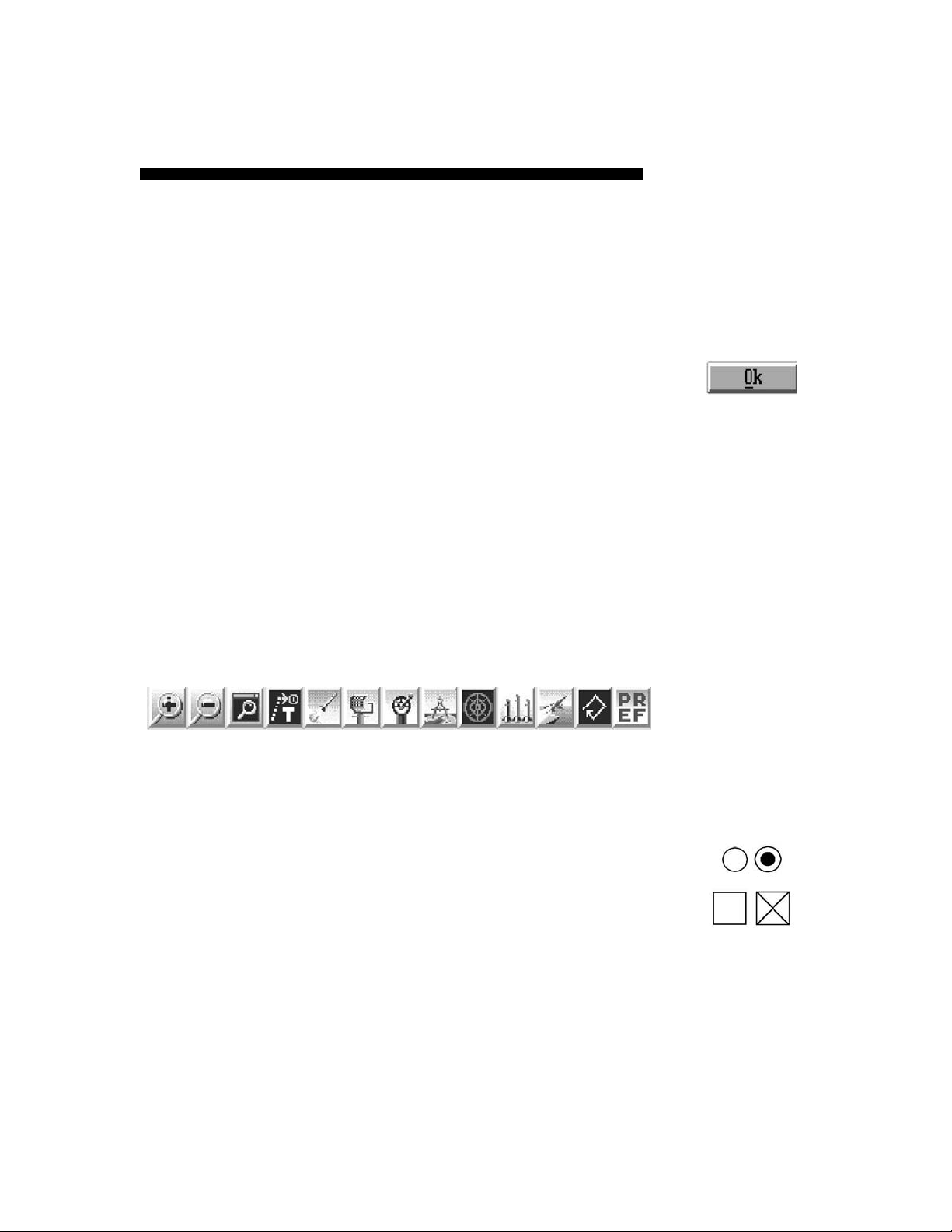
Buttons are raised areas (actually, they are drawn to look raised) on
the screen. They generally represent options available to you within
that window or box. For example, the only button in some dialog
boxes is the one labeled OK, because all you can do is acknowledge
that you have received the information. By contrast, the zoom map
windows have multiple buttons to control game functions.
Toolbar Buttons
Each map window in Harpoon II has a row of colored buttons along the
top of the map. These toolbar Buttons are used to issue a variety of
orders to your groups, units, or bases as well as provide visual
information for each map. Use of each toolbar Button differs slightly.
Each button will be explained later in this manual.
Toolbar Buttons
Radio Buttons/Check Boxes
Many of the dialog boxes and windows in Harpoon II use radio buttons
and check boxes to enable certain game options. Unlike Menu and
Toolbar buttons, Radio buttons and Check boxes have two states:
selected and non-selected.
Menu Button
Mouse Basics
In the interest of making the rest of this manual easier to
9
Radio Buttons
Check Boxes
Page 13

Harpoon II
read, we need to define a few basic mouse concepts.
Operating Instructions
Click
When we talk about a mouse click, we mean quickly pressing the
mouse button and letting it go. In Harpoon II (and other
windowing applications), this is generally the method for selecting an item from a menu or marking a point on a map. You don’t
need to worry about holding down the mouse; how long it takes
to make the click doesn’t matter. For the PC all clicks are made
with the left mouse button with the exception of map centering
which uses a right mouse click. MacintoshTM uses Option-click to
center the map.
Double-Click
A double-click is two clicks as fast as you can do it. In Harpoon
II, double-clicks serve several purposes. As in other windowing
programs, double-clicking in a window’s upper left corner closes
the window (except on MacintoshTM computers, where one click
will suffice). Most menu selections will allow you to double-click
to highlight the particular selection and simultaneously select it,
thus eliminating the need to hit another button such as an OK or
CANCEL button. Also, double-clicking on a target finishes the
targeting procedure for all appropriate functions (from assigning
attacks to landing aircraft).
Drag
A drag is performed by holding down the mouse button and
moving the mouse to a new location. Generally, this operation is
used for making a user-defined box (like a Zoom Map - see below)
or drag-selecting several units. A Drag can also be used to move
an Icon or a Window, both of which will be explained in detail below.
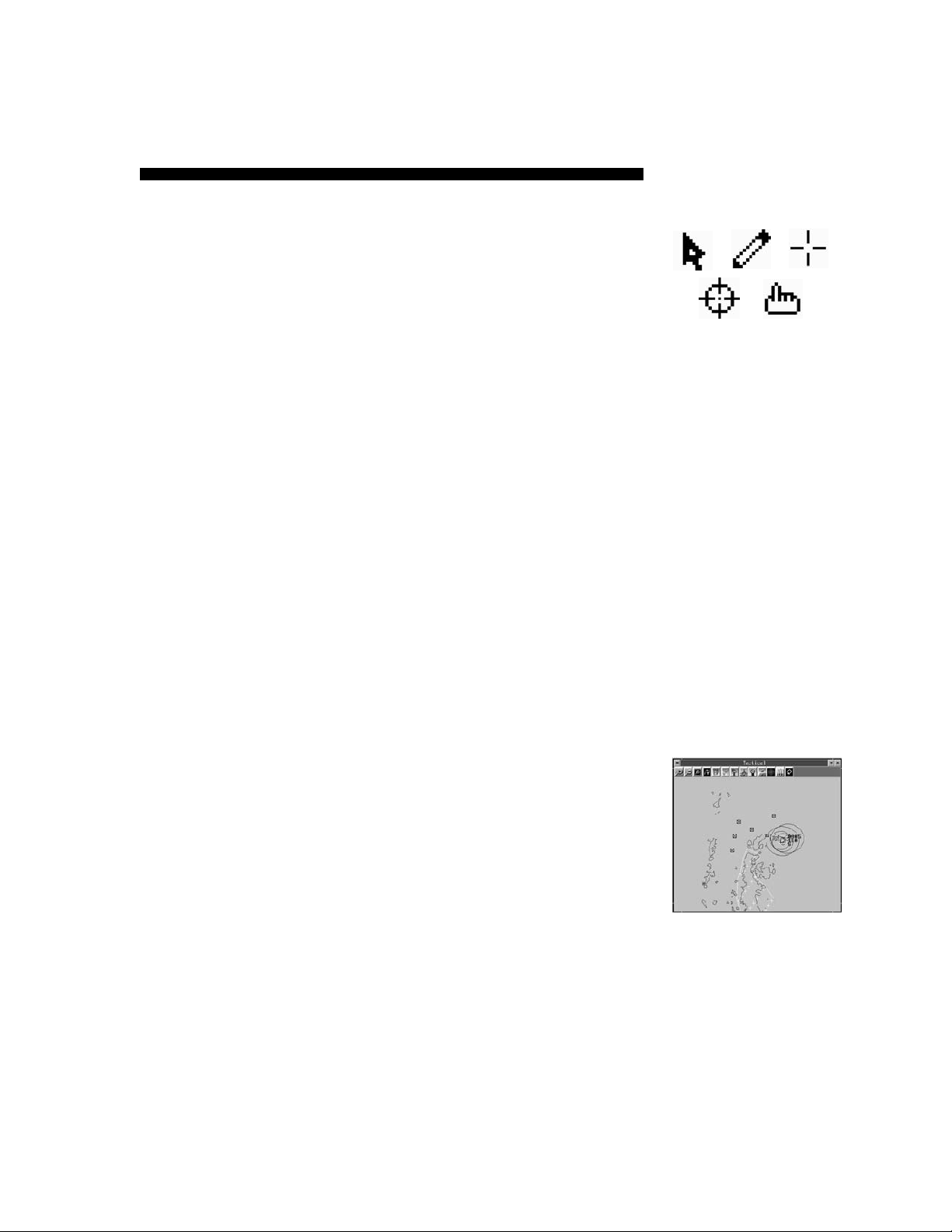
Mouse Pointer
The mouse pointer (generally an arrow) changes shape at different times to indicate different modes. Thus, when you are
choosing a target for an attack, the mouse pointer will look like
a targeting crosshair, while at other times it will be the traditional
arrow, a pointer finger, or one of several other possibilities.
10
Page 14
Interface Basics
Hot Keys
Although the use of a mouse is required to play Harpoon II, many
commands and options may be selected using the keyboard. Throughout this manual the use of individual keystrokes and combinations of
keystrokes are referred to as “hot keys.” Some of the hot keys differ
between PC and MacintoshTM. The Harpoon II Command Card has
been provided with a list of every hot key and toolbar button. Please
review this card to become familiar with the hot keys for your type
of computer.
Windows
A window is a rectangular area of the screen bounded by a border. To
differentiate it from a box, a window is sizable (that is, you can change
its size).
Window Size and Re-sizing
To change the size (and shape) of a window, move the mouse
cursor to the edge of the window; when the cursor changes to a
split arrow, hold down the mouse button and drag the edge of the
window to where you want it. You can also change the size of a
window by clicking on the up arrow in the upper-right corner;
doing so will enlarge the window to its maximum size. If you want
to restore a window to its former size after you’ve enlarged it,
click on the button in the upper right corner with both up and
down arrows. Note that when changing the size of the Main Map
window it will stay proportional at all times since it represents the
entire scenario map area. Zoom and Tracking windows behave
differently as you will see later in the tutorials.
Mouse Pointers
Closing Windows
To close a window, double-click on the bar in the upper left corner.
Note that there is no close button on the Main Map Window since
it can’t be closed.
Moving Windows
To move a window, move the mouse cursor to the title bar, hold
down the mouse button, and drag the window wherever you
would like the window placed. Release the mouse button when
the window is in the area you desire. You should be careful about
dragging a window too far off to the edge of the screen; once you
11
Window
Page 15

Harpoon II
do so, it will become difficult to manipulate it any longer. Also, if
you encounter a situation where one window covers another
there are five ways to gain access to the window “underneath”:
Operating Instructions
• Close the covering window.
• Move the covering window.
• Send the covering window to an icon.
• Click on a portion of the covered window to
bring it to the front.
• Use the Window pull-down menu and select
the menu item in the lower portion of the
menu list that bears the name of the window
that is covered.
Iconizing or Minimizing Windows
To reduce a window to an icon, click on the down arrow in the
upper right corner. An icon will appear bearing the name that was
in the title bar of the window. You can then drag this icon to some
out-of-the-way spot for later use by clicking on it and dragging it
to the new location.
The Macintoshtm interface does not support the iconizing or minimizing
of windows.
Icons
Icons are reduced, miniature windows that you can arrange on the
screen to keep useful information out of the way but still at hand.
For example, if you create a window around a unit to closely follow
its course, you could then iconize that window and move the icon
into a corner of the screen - nicely out of the way. When you want
to see that window again, double-click on it to restore it to its
former size and screen placement.
Enlarging Icons
To restore an iconized window, double click on the icon. The
window will reappear in its original location.
12
Page 16
Interface Basics
Dialog Boxes
A dialog box is a fixed area of the screen bounded by a rectangle.
Unlike a window, a dialog box is not sizable, and often it is not
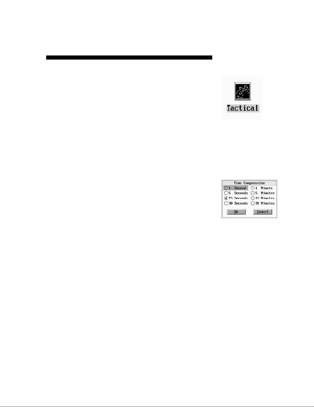
moveable either. In Harpoon II , dialog boxes give you information
from your staff, allow you to give orders to your units, and allow you
to modify game settings like time compression.
Selecting
To do almost anything in Harpoon II, you have to select some item
(a window, a unit, a menu choice, etc.). To select an item, move the
mouse cursor to that item and click the mouse button once.
Selecting Multiple Items
A special case of selecting items is Harpoon II’s ability to allow
you to select multiple items (units, groups, bases, and reference
points). Harpoon II allows you to use two methods of selecting
multiple items. First, you may drag a rectangle around all the
items in an area; all of the items will be selected (though only
appropriate ones will be included in the action). Second, you can
use the mouse pointer and the shift key to select multiple targets.
To do so, hold down the shift key and click on each item you want
to select; then double-click while holding the shift key down on
the last item. This method is useful for selecting some items in
a crowded area with many items (units, bases, or reference
points). Shift-click can also be used to deselect individual items
as well.
Icon
Dialog Box
13
Page 17

Harpoon II
Operating Instructions
14
Page 18

Tutorial
Tutorial
The Harpoon II Tutorial has been designed to take you through a
series of lesson scenarios. These lessons will familiarize you with the
interface while demonstrating how to use each command and menu
function in Harpoon II. The Harpoon II Tutorial is a wise
investment of your time. We understand that you are anxious to start
playing and we have designed the Tutorial so that you may learn
while you play.
Running Harpoon II
If you have not already installed Harpoon II, we recommend you do
so now. Consult the Installation Instructions. Begin the lessons by
running the Harpoon II executable file. Harpoon II was installed in
either the HARPOON2 sub-directory for PC, or the HARPOON II Folder
for the MacintoshTM. Once Harpoon II has loaded and the title screen
and credits have passed, you will see the BattleSet/Scenario Selection Screen. This screen is used to select the BattleSet and scenario
you wish to play during the current Harpoon II session.
Selecting the Tutorial
Select the Tutorial by placing the mouse cursor on the word “Tutorial”
and clicking with your left mouse button
MacintoshTM users simply click the single mouse button.
Tutorial Scenarios
Once you have selected the Tutorial from the Scenario Selection
dialog box, you will see a set of Lesson Scenarios displayed to the
right side of the dialog box. Each of these lessons focuses on a
particular series of commands and functions in Harpoon II .
The following are the Tutorial Lessons for Harpoon II:
Lesson I: Orientation
17
Page 19

Harpoon II Operating Instructions
Lesson II: Course and Speed
Lesson III: Using Sensors
Lesson IV: Using Weapons
Lesson V: Submarine Operations
Lesson VI: Air Operations
Lesson VII: Using the Mission Editor
Lesson VIII: The Formation Editor
Loading a Scenario
We will start with Lesson I: Orientation . Select the first scenario
of the tutorial by either double-clicking on the scenario name or by
clicking once on the scenario name and then once on the OK button
located in the lower left area of the Scenario Selection dialog box.
Scenario Load Status
While the scenario is loading watch the Incoming Message Window to see the various portions of the scenario as they are loaded
into the computer’s memory.
Cross Platform Loading and Saving
Harpoon II supports cross-platform loading and saving. Scenarios
and saved game files can be opened and saved on either the PC or the
MacintoshTM. NOTE: Attempting to load a game saved from a scenario
that was part of a Battleset you do not own will produce unpredictable
results.
Choosing Sides
Once the scenario has loaded, you will be asked to choose sides. Click
on Good Guys.
Setting Difficulty Level
Press the Difficulty button to set the level of difficulty for the scenario
you will be playing.
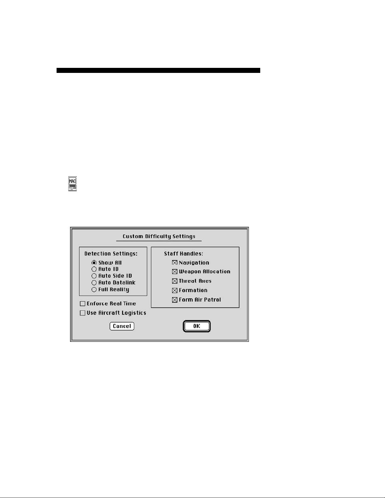
On the PC, You have four choices:
18
Page 20
Tutorial
• Easy Beginner settings
• Average Novice settings
• Hard Expert settings
• Default User defined settings
• Custom Modifies difficulty settings
The initial setting for Harpoon II is Default. For this tutorial select
Easy and then OK. A more detailed explanation of Difficulty Levels
and how to customize your default settings can be found in the
Reference Section.
On the MacintoshTM version there is a Difficulty Settings dialog box that
allows you to toggle the individual difficulty settings. Selecting OK saves
those settings to a preferences file, which will then be used each time the game
is played.
Macintosh Difficulty Settings Dialog box
Viewing Orders
After selecting your side and setting difficulty level, it is time to
review your orders. Take a moment to read the scenario orders on
the right side of the Side Selection window. You can use the scroll
bar at the side of the orders window to read all of the orders. These
orders can also be viewed at anytime while you are playing the game.
Once you have reviewed your orders, click on OK.
19
Page 21

Harpoon II Operating Instructions
20
Page 22

Tutorial Lesson I: Orientation
Lesson I: Orientation
Now that you have selected your side, examined your orders, and the
scenario has been loaded, it is time to become familiar with the
Harpoon II screen and the components of the interface.
Main Window
The Main Window depicts the entire map area of the scenario. In the
Lesson I scenario the Main Window is currently in icon form and labeled
“Lesson I.” Go ahead and double-click on the icon. The window will
expand and the entire map area will be displayed. For this first Tutorial
scenario the only map features that are active are the coastlines and
a single unit symbol. The unit represented here is the USS Lewis B.
Puller. We’ll learn more about the Puller later in this lesson.
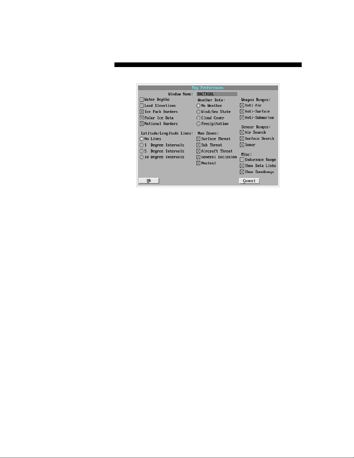
Map Preferences
Let’s go over the components of the map. The map area itself is
where the ocean, coastlines, groups, units, and bases are displayed.
At the top of the display area is a toolbar containing the buttons used
to issue orders to your units or change the window’s features. To
activate the various display options, click on the toolbar button
marked PREF. This is the Map Preferences button and will display an
options screen with a variety of display options which may be
selected. It is important to note that you may set a combination of
display preferences in each individual window. Each window may have
an independent set of preferences. Use this feature to create
windows containing a variety of display information. Let’s try out the
various Preferences. Go ahead and select the PREF toolbar button
from the Main Window. The Map Preferences box should now be
in the center of your screen.
PREF Toolbar
Button
21
Page 23
Harpoon II Operating Instructions
Map Preferences Dialog Box
Window Name
To change the name you see displayed in the title bar of a window,
click on the text field containing the current window name and
type the name you desire. Go ahead and change “Lesson I” to
“Lesson One” or to whatever you want to name the window. You
can change the window names to whatever you want during a
game to keep track of various areas, units, or groups. Be aware
that large window names will not be practical when you have the
map window in icon form. Use small names or abbreviations when
naming windows.
Water Depths
Water depths are represented by colored tick marks every 30
minutes of map distance. This is one-half degree or 30 nautical
miles at the equator. The water depth scale is represented for
three levels, sea level to 10 meters, 10 to 100 meters, and 100
to 1000+ meters. Select Water Depths and click on OK. You
should now see colored tick marks representing the various
depths of the ocean represented on the map. Go ahead and click
the PREF button again to return to the Map Preferences window.
Click the Water Depths selection so it is turned off.
22
Page 24

Tutorial Lesson I: Orientation
Land Elevations
Land elevations can be displayed in 500 meter bands starting at
sea level (0 meters) and going up to 2500 meters. Each band can
be represented by a colored tick mark. Like water depths, tick
marks are placed in 30 minute intervals on the map. The color of
the tick mark indicates the elevation for that particular area on
the map. The size of the tick mark will depend on the size of the
map area represented by the map window and the level at which
the map is magnified. We will learn more about changing the
magnification level of the map and how to determine the various
altitude colors later in this tutorial. For now, select the Land
Elevations box and click the OK button. You should now see
various colored tick marks representing the elevations of the land
masses on the map. Go ahead and click the Map Preferences
button again to return to the Preferences window. We are going
to leave the elevations off for now while we look at some other
display features. Click the Land Elevations selection so it is turned
off.
Ice Pack Borders
To display the polar ice pack borders, click on the Ice Pack Borders
selection. The ice packs will only be displayed in scenarios taking
place close to the polar regions of the world. Surface ships cannot
traverse across polar ice. The ice packs are represented on the
map as a line similar to coastlines. Think of it as a variable
coastline which changes with the seasons. Because this scenario
does not take place in a polar region, ice packs can not be viewed
from this first tutorial scenario. Leave this selection off (no “X”
in the small square) for now.
Polar Ice Data
Polar Ice Data is provided every half-degree of map distance.
When this selection is ON, the entire area defined by the Polar Ice
Borders will be displayed. Leave this selection off for now.
National Borders
To display national borders on the map click on this item in the
Preferences window. The selection is active if there is an “X” in
the small square. Borders are represented as lines within the land
masses on the map. Select this box and click on the OK button.
You should notice there are now several lines representing
borders on the land masses. Now select the PREF toolbar button
23
Page 25

Harpoon II Operating Instructions
again to bring back the preferences listing. You can leave the
borders on or off, the choice is yours.
Latitude & Longitude Lines
Latitude and longitude can be represented on any map. You can
choose to have no lines, or lines at either 1, 5, or 10 degree
intervals. Go ahead and try it out. When you have finished looking
at the lines, select No Lines to avoid cluttering the screen as we
examine other aspects of the display.
Weather Data
Harpoon II contains a global weather model that creates the
weather conditions most likely to be found in the geographic
region in which the scenario takes place. The following weather
display choices are available:
No Weather
No weather information will be displayed on the map.
Wind & Sea State
Color coded tick marks similar to the land elevation and depth
information will be displayed. The colors vary with the speed
of the wind in each half degree interval.
Cloud Cover
The color tick marks represent the type of cloud cover in a
given area. The categories for cloud cover are clear, scattered, partly cloudy, and overcast.
Precipitation
The color tick marks represent nine categories of precipitation. The categories include three levels of fog, three levels
of rain, and three levels of snow. No precipitation is present
if no tick marks are displayed.
Nav Zones
Navigation or “Nav” Zones are areas that you can designate as
off-limits to all or some of your units. We will explore how to
create and use Nav Zones later in the tutorial. For now, we are
24
Page 26

Tutorial Lesson I: Orientation
interested in the types of Nav Zones and how to display them on
the map.
Surface Threat
A Surface Threat Nav Zone will exclude all surface ships from
entering the zone. Aircraft and submarines are unaffected by
this type of Nav Zone. You may create, modify, or delete this
type of Nav Zone.
Sub Threat
A Sub Threat Nav Zone will exclude all submarines from
entering the zone. Aircraft and ships are unaffected by this
type of Nav Zone. You may create, modify, or delete this type
of Nav Zone.
Aircraft Threat
An Aircraft Threat Nav Zone will exclude all aircraft from
entering the zone. Submarines and ships are unaffected by
this type of Nav Zone. You may create, modify, or delete this
type of Nav Zone.
General Exclusion
A General Exclusion Nav Zone will exclude all units, aircraft,
ships, and submarines, from entering the zone. You may
create, modify, or delete this type of Nav Zone.
Neutral
Similar to a General Exclusion Nav Zone, a Neutral Nav Zone will
exclude all units, aircraft, ships, and submarines, from entering the zone. You may NOT create, modify or delete a Neutral
Nav Zone. Most Neutral Nav Zones will be created when the
scenario is designed and will be present from the start of the
scenario.
To display the various Nav Zones, you would select each one so
an “X” appears in the boxes. There are no Nav Zones in this first
lesson. We will explore their use later in the tutorial.
25
Page 27

Harpoon II Operating Instructions
Weapon Ranges
To display the approximate ranges of your weapons, place an “X”
in the boxes next to the following:
Anti-Air Warfare (AAW)
Displays a ring depicting the approximate range of the
farthest reaching AAW weapon for each platform.
Anti-Surface Warfare (ASuW)
Displays a ring depicting the approximate range of the
farthest reaching ASuW weapon for each platform.
Anti-Submarine Warfare (ASW)
Displays a ring depicting the approximate range of the
farthest reaching ASW weapon for each platform.
Once you have all the items selected with an “X”, click on the OK
button. You should see several colored rings around the Puller
representing the approximate ranges of its weapons.
Sensor Ranges
To display the approximate ranges of your sensors, place an “X”
in the boxes next to the following:
Air Search
Displays a ring depicting the approximate range of the
farthest reaching AAW sensor for each platform.
Surface Search
Displays a ring depicting the approximate range of the
farthest reaching ASuW sensor for each platform.
Sonar
26
Page 28

Tutorial Lesson I: Orientation
Displays a ring depicting the approximate range of the
farthest reaching ASW sensor for each platform.
Once you have all the sensor items selected with an “X”, click on
the OK button. Since we do not have any sensors activated, the
only sensor range circle that you should see is the Puller’s passive
sonar.
Range Rings and Groups
Range rings are not displayed while in group view. To view
approximate range rings, make sure all desired display options are
set in the Map Preferences dialog box, then press the Unit View
hot key.
Data Links
Data Links are used to relay communications, sensor, and contact
information between platforms. Data links can only be established between units with operational communications equipment
that are in range of one another. A data link provides the ability
to “see” things from the point of view of another platform. Think
of a data link system as a network of sensors and communications
equipment. If you select the Data Links selection, the links will be
represented by thin lines between the data link capable platforms
on your side. We will take a look at data links later in the tutorial
when we have more platforms on the map. Go ahead and leave
the Data Link selection on.
Show Sonobuoys
Place an “X” here to display individual sonobuoys on the map.
Sonobuoys are dropped into the water by Anti-Submarine aircraft
and have their own sensor range circles and data link lines.
Because many sonobuoys on the screen can clutter the view, it
is a good idea to only use the Show Sonobuoys display option in
windows that are being used for ASW operations.
Endurance Range
Place an “X” here to show the approximate range each platform
has based upon its current fuel state. The endurance circle for the
Puller is very large so it will not show up on your map, so we will
not select it at this time. Endurance circles for aircraft are more
27
Page 29

Harpoon II Operating Instructions
noticeable as they have much shorter ranges and use fuel at a
faster rate than either ships or submarines.
Tutorial Settings
For the purposes of this tutorial you should have the following
settings for Map Preferences:
Water Depths: OFF
Land Elevations: OFF
Ice Pack Borders: OFF
Polar Ice Data: OFF
National Borders: OFF
Latitude/Longitude: NO LINES
Weather: NO WEATHER
Nav Zones: All OFF
Weapon Ranges: All ON
Sensor Ranges: All ON
Data Links: ON
Show Sonobuoys: ON
Endurance Range: OFF
Creating Zoom Windows
A Zoom Window can be created by first clicking on the Zoom Window
toolbar button. The mouse cursor should now resemble a “+”. Place
the mouse cursor at any location on the Main Map area and drag a box
as you hold the mouse button down. Once you release the mouse
button, a new map window will appear. The new window is a Zoom
Window labeled “Zoom Map 1.” Note this new window has its own
toolbar buttons. A Zoom Window will have the same preferences as
the map from which it was originally created. If you wish to have
different settings, use the Map Preferences button (PREF) for this
28
Page 30

Tutorial Lesson I: Orientation
new window to give it its own display parameters. Click on the PREF
button in this new Zoom Window and rename it “Tactical View”. Now
grab the corner of Tactical View zoom window and stretch the
window so it’s big enough for you to see all of the toolbar buttons for
this window. Unlike the Main Map window, zoom windows do not stay
proportional and can be stretched to any size without distorting the
map.
Centering the Screen
Since the map area displayed in the new Zoom Window is smaller than
the Main Map, you can move around within the map and center it on
any location. To center the map place the mouse cursor on the point
you wish to designate as the new center of the map and click the right
mouse button for PC or Option-click for MacintoshTM. The map should
now be centered on the point where you clicked. Try it by clicking
around and making various points on the map the center. This is a
rapid means of traversing across the map surface in any direction.
Zoom In & Out
The new window has three toolbar buttons that were absent from the
Main Map. The first two buttons are Zoom In and Zoom Out. Use these
buttons to magnify or expand your view in the map. Try clicking the
Zoom In button three times and watch what happens to the view in
Tactical View. It should zoom in towards the map. Now click on the
Zoom Out button three times. Doing this should have expanded the
view back to where it was prior to using the Zoom In button. Go ahead
and center the map on several areas using the center map feature
described above and use the Zoom In and Zoom Out buttons to
change the magnification of the view. For example, try centering the
map on a coastline and then zoom in and out or center on the Puller
and change the magnification. When you are comfortable with how
these two buttons function, center the map around the Puller and
zoom out enough to where you can see the Puller and some of the
coastlines.
Zoom Window
Toolbar Button
Creating Tracking Windows
Another toolbar button not found on the Main Map is the Tracking
Window button. A Tracking Window allows the user to select a unit
or group and center the map screen continuously on that unit or
group. This means the window will keep the selected unit or group
in the center of the window as it moves across the map. To create
a Tracking Window, select the Puller. Next, click on the Tracking
Window toolbar button. This should center the window on the Puller
29
Page 31

Zoom In/Out
Toolbar Buutton
Tracking Window
Toolbar Button
Harpoon II Operating Instructions
and the title bar for the window should now read “Tracking.” You can
use the PREF button to rename the window whatever you choose. Go
ahead and name the window “Tracking USS Puller.” A Tracking
Window can be changed back into a regular Zoom Window by clicking
on the Tracking Window toolbar button again. Try it now. As you can
see, the window returns to a normal zoom window and if you select
tracking window again, the map centers on, and follows, the Puller.
You will have to rename the tracking window each time you go from
a tracking window to a normal zoom window. Go ahead and rename
the window “Tracking USS Puller.”
Additional Window Types
There are a variety of windows used by the Harpoon II interface to
display information. We have already learned about the map windows, now we will take a look at the other types of windows that can
be displayed using the Window pull-down menu.
Game Status Window
The Game Status Window provides you with the current game
time, and time compression ratio. In this tutorial scenario the
Game Status Window is already active. If it had not been, you
would have needed to select Game Status Window from the
Window pull-down menu. The Game Status Window can be
moved anywhere on the screen. To display the Game Status
Window after it has closed, use the Window pull-down menu
selection and select Game Status Window. As you can see, the
current game time is 12:00 noon on January 1, 1994 and the
game is currently paused. The time is displayed in Greenwich
Mean Time (GMT) which is also referred to as “Zulu” time.
30
Zulu Time
Zulu time is used as a standard time reference for aviation and
maritime navigation. GMT (Greenwich Mean Time) is named
for Greenwich, England, the location of the Royal Observatory
which the Prime Meridian (zero longitude) passes through.
Using Zulu time puts all aviators and mariners in the same time
zone regardless of their geographic location. Although your
forces may be operating using Zulu time, the light conditions
due to the position of the sun depend on the location. For
example, if you are operating off the coast of Japan and it is
Page 32

Tutorial Lesson I: Orientation
12:00 Zulu (noon GMT) it will still be night where you are
located as the local time will be in the evening.
Unit Status Window
The Unit Status Window contains information relating to the
current unit or group that is selected. The unit Status Window is
already active in this tutorial scenario so we do not need to use
the Window pull-down menu to create it. If the Unit Status
Window was not active, you would need to select Unit Status
Window from the Window pull-down menu. Go ahead and select
the ship symbol in the middle of the main window. The Unit Status
Window should now show you that the selected ship is the USS
Lewis B. Puller, an Ingraham class guided-missile frigate, operat-
ing on the side of “The Good Guys.” The Puller has a speed of 5
(creep) and has no damage. The current endurance in hours and
the current Emission Control (EMCON), state is displayed. The
Puller is not currently assigned to a mission and awaits your
orders. Had the Puller been an aircraft, submarine, or unknown
contact, the Unit Status Window would differ slightly. We will
note the differences for these other types of platforms later in
the Tutorial. There are two buttons in the Unit Status Window,
the Database button and the Report button.
Game Status
Window
Database
Finally, click on the Database button. Selecting this button
brings up the Platform Database entry for the USS Puller. You
can also view the platform database by selecting the Platform
Display selection from the Window pull-down menu.
Database Display
31
Page 33

Harpoon II Operating Instructions
Platform Selection Buttons
You can view detailed information on ships, weapons,
subs, aircraft and facilities by clicking on the corresponding button in the database window. Press Show All (or
Show Selected) to toggle between the currently selected
unit and all of the items in the Harpoon II database.
Sensor and Mount Data
Unit Status Window
It is possible to view weapons and sensor information by
clicking the corresponding Sensors and Mounts buttons
on the database window. Close these windows by double-
clicking the button in the upper-left corner.
Platform Text
Scroll through the data text for the Puller to learn more
about its specifications and to read a brief description of
the O.H. Perry-class guided-missile frigate.
Displaying Platform Image
To view a diagram and photograph of the Puller, click on
the Picture button in the lower right corner. A window
containing a line diagram and photograph of the ship class
will appear on your screen. This window is dependent on
the database window. The image window will remain until
you double-click in the upper left corner or close the
database window. Closing the image window will not
affect the platform database window.
Report
32
Click on Report in the Unit Status window for detailed
information about the current unit or base selected. The
Report provides more detailed information than the Unit
Status window. Go ahead and click on Report. You will see
sections of the Report window listing the weapons and
sensors available to the Puller. You can use the scroll bar at
the side of each section to view the entire weapon and sensor
Page 34

Tutorial Lesson I: Orientation
list. Go ahead and close the Report when you have finished
reading it.
Order of Battle
Click on the Order of Battle selection in the Window pull-down
menu to produce a listing of all the groups, units, and bases that
are currently under your command. Close the Order of Battle box
when you are finished viewing it.
Legends
There are four legends to provide you with information about
symbols and colors used to represent units & groups, map
components, sensors, weapon ranges, and weather. Go ahead
and select Legends from the Window pull-down menu and then
select each of the following from the Legends sub-menu:
Symbol Legend
A legend depicting the symbols that represent various unit,
group, base, and other “game pieces.”
Map Legend
A legend depicting the colors used to represent various
elevation, depth, weather, and Threat Zones.
Tactical Legend
A legend depicting the colors used to represent various
sensor & weapons ranges, as well as contact status.
Weather Legend
A legend depicting the colors used to represent various
weather-related information.
System Memory Remaining
To view the amount of system memory Harpoon II is using at
anytime select Memory Remaining from the Window pull-down
menu. Go ahead and select it now. This selection will provide you
with the following information about memory being used by
33
Platform Image
Page 35

Harpoon II Operating Instructions
Harpoon II:
• Memory available at the start
of the scenario.
• Memory used by the interface.
• Memory used by the game engine.
• Largest block of memory left.
• Total memory left.
On the PC, these values will probably be larger than the actual amount
of system RAM present in your computer. Harpoon II implements virtual memory
which uses some of your hard drive when required.
Incoming Messages Window
This is where text information is presented. This window is
already active for this tutorial scenario. Information about
contacts, threats, and your own Damage Control will be displayed
in this window. The location and size of the Incoming Messages
window is up to you. It will appear at the bottom of the screen
before and during the process of loading a scenario. After the
scenario has loaded, the Incoming Messages window may appear
in another location or may not appear at all, depending on how the
scenario screen layout was saved when the scenario was last
exited. You can also re-size the Incoming Messages window to
your liking. The following information is displayed in the Incoming
Messages window:
34
Range and Bearing
If you select Toggle Rng/Bearing and click on it so that it reads
[ON] from the Settings pull-down menu, the range and
bearing between mouse clicks on any map window will be
displayed in the Message Window. Altitude/depth and lighting conditions are also provided for each point. Go ahead and
select the Settings pull-down menu and click Toggle Rng/
Bearing so it reads [ON]. Now click anywhere on the map;
do it several times and note the changes in range and bearing
as you click. Once you are comfortable with the use of this
feature, please turn it [OFF] until we need it later in the
Tutorial. This feature may be toggled on and off with a hot
Page 36

Tutorial Lesson I: Orientation
key. Consult the Harpoon II Command Card for details.
Scenario Load Status
The Message Window is the only window you will see on the
screen as a scenario is loading. While a scenario is loading, it
will indicate the various portions of the scenario that are being
loaded into the computer’s memory.
Platform Hit/Destroyed
When a platform is hit, sunk, or destroyed a text message will
appear in the Message Window. If this event type is selected
in the Game Settings then this text will also appear in a Staff
Message Box.
New Contacts
When a platform is detected a text message will appear in the
Message Window. If this event type is selected in the Game
Settings then this text will also appear in a Staff Message Box.
System Memory
Window
Contact Change
When a contact is lost a text message will appear in the
Message Window. If this event type is selected in the Game
Settings then this text will also appear in a Staff Message Box.
General Information
General information regarding aircraft ready status, damage
reports, mounts reloading, and other information will appear
as text messages in the Message Window. If this event type
is selected in the Game Settings then this text will also appear
in a Staff Message Box.
Current Orders
You can review your orders at anytime by selecting Current
Orders from the Window pull-down menu. The orders are
identical to the ones you viewed earlier after side selection. It is
not necessary to have the orders displayed during the game. If
you desire, the Current Orders text can be reduced to an icon so
that you can easily review them from time to time by double-
35
Incoming
Messages Window
Page 37

Harpoon II Operating Instructions
clicking on the icon.
Scenario Info
You can review text information about the scenario you are
currently running by clicking on Scenario Info from the Window
pull-down menu. This information is identical to the Scenario Info
available when selecting a scenario.
Display Features
The display features for Harpoon II are very flexible. The user may
customize the display by changing the colors used or selecting from
one of two sets of symbols.
Colors
Harpoon II provides the user with the ability to change the colors
used to represent the interface, maps, and the game elements
(such as symbols). There are three ways to change the colors but
for the purpose of this tutorial we will only be covering one of
them. Select Colors from the Settings pull-down menu. A submenu should now appear to the side of the Settings menu, click
on Default Palettes. You will be given the following five choices:
• Aegis Display
• Amber Display
• OJ-663 Display
• Greyscale Display
• Conventional Display
Go ahead and select Aegis Display. Doing this should change the
map colors on your display. Now, try the other selections. The
OJ-663 Display is the initial default setting for Harpoon II. For
the purposes of this tutorial please reset the palette to OJ-663
before continuing with the tutorial lessons. More information
about customizing and setting colors is contained later in this
manual.
Choosing a Symbol Set
Select Symbol Set from the Settings pull-down menu. A sub-menu
36
Page 38

Tutorial Lesson I: Orientation
should appear offering the choice of either Stylized or NTDS symbols.
Stylized
Stylized symbols are more intuitively understood and are drawn
to resemble various platforms. Because they are easier for new
players to recognize, the stylized set is the initial default set for
Harpoon II.
Stylized Symbols
NTDS
Naval Tactical Display System symbols are based upon the
symbols used by actual military systems. Harpoon II has been
designed to resemble these actual military systems. To achieve
true realism, users may consider learning and using the NTDS
Symbology. After all, millions of your tax dollars went into the
design of these symbols to make them easy to recognize. The
Harpoon II Design Team invites you to learn these symbols and
play Harpoon II as realistically as possible. They were designed to
convey information without relying on context. This is important
when a screen is crowded with symbols, time-pressure is high, and
you are approaching information overload. Users can instantly
see the relations and capabilities of a threat presented by a
symbol with a minimal amount of thought.
37
Page 39

Harpoon II Operating Instructions
NTDS Symbols
Lesson Summary
That concludes Lesson I: Orientation . If you followed each step
of the lesson you should now be familiar with each element of Harpoon
II’s interface. You also learned to move about a map and how to create
Zoom Maps and configure them to display a variety of information.
Now that we are finished with the first lesson, let’s move on to the
next lesson. Select the File pull-down menu and choose Load
BattleSet. Once you have the BattleSet Selection menu up, go ahead
and choose the Tutorial BattleSet and click on Lesson II: Plotting
Course & Speed.
38
Page 40

Tutorial Lesson I: Orientation
39
Page 41

Tutorial Lesson II: Course and Speed
Lesson II: Course & Speed
After you have selected Lesson II, choose Good Guys as your side.
Leave the Difficulty Settings as they are currently set.
You should now be looking at a display almost identical to the Lesson
I. Once again, the USS Lewis B. Puller is the lone unit on the map. We
will be using the Puller to become familiar with navigation procedures
for Harpoon II.
Notice that there are three small “X’s” located at various points on
the map. These are Reference Points. We will be using them to assist
us in our navigation lesson.
Showing Data Blocks
A Data Block is the text information displayed next to each unit,
group, base, or reference point. Use the Show Data Blocks hot key
to toggle the data block settings. There are three settings for Data
Blocks:
• Data Blocks Off for all units.
• Data Blocks On for all units.
• Data Blocks On for the selected unit only.
Go ahead and try it. Press the Show Data Blocks hot key several times
and watch the map display. Also notice that the current setting is
displayed in the Incoming Messages window. Data Blocks provide
Unit/Group Designator (or name), course, speed, and when appropriate, altitude/depth. You should set Data Blocks On for all units for the
remainder of this tutorial lesson.
Drawing & Plotting a Course
Let’s start by plotting a course to Reference Point 1. Select the Puller
and then click on the Navigation toolbar Button. Your mouse cursor
should now change into a pencil shape. Place the cursor at a point
about one-third the distance from the Puller to Reference Point 1 and
click with your mouse button. A line should appear from the unit
symbol to the point where you clicked the mouse. If a line does not
appear, try the course tracks hot key that toggles the display of
course tracks for all units, the selected unit, and no tracks at all.
Consult the Harpoon II Command Card to determine the correct key
Navigation Toolbar
Button
Pencil Mouse
Cursor
41
Page 42

Harpoon II Operating Instructions
for toggling the course tracks. Once you are looking at the line you
just created, notice at the point the line ends there is a small circle.
This circle is called a waypoint. Halfway between the unit symbol and
the first waypoint is a small triangle, this is called a midpoint. We will
examine both the waypoint and the midpoint shortly. For now, let’s
resume plotting our course to Reference Point 1. Go ahead and place
the mouse cursor on a point that is two-thirds the distance from the
Puller to Reference Point 1 and click on that spot. Another line
segment with a waypoint and a midpoint should appear. Now let’s
finish our course. Place the cursor at a point just beyond Reference
Point 1 and click. A third line segment, waypoint, and midpoint should
appear. You have now finished drawing the course to Reference Point
1. We are finished plotting the course so we need to exit the
navigation mode. Place the mouse cursor on the navigation toolbar
button and click once. The Navigation toolbar button should come
back up and your mouse cursor should now be back to normal (an
arrow). After clicking on the toolbar button the Navigator now
examines the course you have drawn and plots it. While you are in
navigation mode, you are drawing the course and when you exit
navigation mode, the course is actually plotted and assigned to the
unit or group.
Moving a Waypoint
Suppose you want to change the course you just plotted. Let’s
examine how to edit our existing course. First, let’s say that we want
to change the location of the final waypoint of our present course.
Start by clicking on the third waypoint. It should change color to
indicate that it has been selected. Click on third waypoint and hold
down on the mouse button to grab it. Now move the mouse to drag
the waypoint to a new location. Notice the outline of the course
segment from the second and third waypoints now appears as
another color and moves as you move the mouse. Drag the third
waypoint a short distance from its original location and release the
mouse button. The course will change to the new location.
Inserting a Waypoint
To insert a waypoint between two existing waypoints, grab the
midpoint between two waypoints and drag it to the place you wish to
insert the new waypoint. When you release the mouse button a new
waypoint, course segment, and midpoint are all created. Go ahead
and create a new waypoint by dragging one of the midpoints a short
distance from its present location and releasing the mouse button.
42
Page 43

Tutorial Lesson II: Course and Speed
Deleting a Waypoint
To delete an existing waypoint drag it to an adjacent waypoint and
release the mouse button once the waypoint is placed in the same
position as another waypoint. Try deleting the waypoint you just
created.
Editing a Course using the Navigation Mode
You can also edit a course with the Navigation Mode used earlier to
create the original course. Select the second waypoint and then click
on the Navigation toolbar button. The course from the second
waypoint has been deleted. Since you are now in Navigation Mode,
click on a new point near Reference Point 2. A new course segment
should appear. Click on the Navigation toolbar button and this new
course will be plotted. You can revise a course using this procedure
from any waypoint including the current location of your unit or group.
Clicking on the unit or group clears any other waypoint from being
selected. When you have clicked on the unit or group you are now at
waypoint 0. Waypoint 0 is constantly changing as it is the current
location of the unit or group. If you click on the Navigation toolbar
button while on waypoint 0, your entire course will be deleted. Be
careful when using the Navigation toolbar button with a unit or group
that already has a course plotted.
Using the Navigator
The Navigation routine used by Harpoon II (referred to as “Navigator”) ensures that the course you have drawn does not violate Nav
Zones and, in the case of ships and submarines, does not traverse
land. When a course is drawn that would take a unit or group through
one of the above mentioned regions, the Navigator will plot a course
around the area. Let’s try it out. Select the Puller and then click on
the Navigation toolbar button. Any previous course plotted is now
deleted. Draw a course directly to Reference Point 3, even though
the course goes right through land to reach the destination. Now,
click on the Navigation toolbar button to plot the course. The
Navigator will begin to work on plotting the best course around the
land mass. This will take a few seconds, so don’t be surprised if the
course is not plotted immediately. If you look carefully you should see
dotted lines appear as the Navigator evaluates several courses to
reach the final destination. Once the Navigator has found the
optimum path, it will complete the plot. You can now edit the course
manually if you wish. Go ahead and keep the course to Reference
Point 3 as we move on in the lesson to learn about setting speed.
43
Page 44

Speed/Altitude/
Depth Toolbar
Button
Harpoon II Operating Instructions
Setting Speed
Ensure that you have selected the Puller (waypoint 0) and then click
on the Speed toolbar button. A menu box will appear that allows you
to set your speed to one of the following:
• Stop: Engines disengaged, speed set to zero.
• Creep: Engines engaged at low speed. Optimum
passive sonar speed. Actual speed varies
between ship and sub types.
• Cruise: Engines engaged at intermediate speed. Opti mum fuel efficiency achieved. Actual speed varies
between ship and sub types.
• Full: Engines engaged at high speed. Maximum speed
available for sustained periods of time without suffering
an engine casualty. Fuel consumption rate is
greatly increased. Actual speed varies between ship
and sub types.
• Flank: Engines engaged to maximum speed possible.
Fuel consumption rate is very high at Flank. To be used in
urgent or emergency onditions only. Actual speed varies
between ship and sub types.
Speed Selection
Dialog Box
Beside the above settings, a speed can be entered in the text block
provided with the Speed/Altitude/Depth menu box. Go ahead and
select the Cruise setting and click on OK. You have now set the initial
speed for the Puller.
Waypoint Orders
Certain orders can be preset to be executed upon reaching a
waypoint. For example, we can create an order for the Puller to
change speeds once it reaches the first waypoint. Let’s try it. First,
select the first waypoint. Next, click on the Speed/Altitude/Depth
toolbar button. The same menu box that we used to set the Puller’s
initial speed will appear. Choose Full and click on the OK button.
When the Puller reaches waypoint 1, it will change from Cruise to Full.
44
Page 45

Tutorial Lesson II: Course and Speed
Nav Zones
Nav Zones were briefly covered in the last lesson so you should have
an understanding of the various types of Nav Zones. We are now
going to create a Nav Zone and see what effect it has on navigation.
Create a Nav Zone
Prior to creating a Nav Zone, make sure that you have Nav Zones
set to display from the Map Preference window. To create a Nav
Zone start by clicking on the Nav Zone toolbar button. Your
mouse cursor should change into a pencil cursor identical to the
one used while in navigation mode. Place the mouse cursor at a
point near waypoint 1 and start clicking and moving the mouse
around the waypoint. Draw a box around the waypoint with the
line segments created each time you click. When you reach the
point where you are ready to close the polygon you just created,
click on the Nav Zone button again, the polygon will close
automatically. A dialog box should appear with a variety of
exclusion zones to choose from. Select General Exclusion A and
hit the OK button. The line segments should change into one line
making up the polygon with a small circle at the point where you
first clicked to begin drawing the polygon. This circle is used to
select the polygon to edit or delete it.
Editing a Nav Zone
Go ahead and select the circle. Note that when selected, the
individual points you used to create the polygon appear. These
polygon nodes can be moved and deleted exactly like the
navigation waypoints. We will cover deleting a Nav Zone after we
have used this particular Nav Zone to demonstrate navigation
around and through it.
Navigating Around Nav Zones
Now that we have a Ship Exclusion Nav Zone around waypoint one,
let’s try to navigate through it. Select the Puller again, click on
the Navigation toolbar button and draw a course through the Nav
Zone you just created. The Navigator will plot a course around the
Nav Zone in a manner similar to the way the course was plotted
around land to Reference Point 3 in the earlier example.
45
Nav Zone Toolbar
Button
Page 46

Harpoon II Operating Instructions
Navigating Through Nav Zones
You may require that a unit ignore a Nav Zone because it is critical
for the successful completion of the mission to get to a spot
inside. To navigate through the zone, start by selecting the unit
or group that you want to navigate through the zone. Next,
double-click on the Nav Zone toolbar button. The menu box used
to designate Nav Zone types will appear with an “X” in every type
of Nav Zone that the selected unit or group currently respects. In
our case, click on the General Exclusion A box to clear it and then
click on OK. The selected unit will now ignore any Nav Zone that
has this type. If the polygon has other types selected, the unit
may avoid for those reasons. It is important to check and see if
a Nav Zone has multiple types before attempting to navigate
through with the ignore feature. Try it out. Plot a new course
through the Nav Zone you created earlier. The Navigator will now
plot a course through this type of Nav Zone. To restore the
original settings for the selected unit, simply repeat the process
and place an “X” in the box as it was before.
Deleting a Nav Zone
To delete a Nav Zone, select the Nav Zone you wish to delete and
then double-click the Nav Zone toolbar button. The Nav Zone
type menu will appear again. Click on the “X” representing the
selected Nav Zone type and remove it. This will delete the
Selected Nav Zone. Go ahead and delete the Nav Zone you
created earlier.
Run the Game
Go ahead and select Resume/Start from the Settings pull-down
menu. The game will now start and the Puller will begin to move on
the course plotted. As the game runs, you can edit the course at
anytime. Go ahead and create or move a waypoint so that waypoint
1 is close to the Puller. Select waypoint 1 and click on the Speed
toolbar button. Choose Full to give the Puller a speed change at
waypoint 1 as we did earlier in this lesson. If you want, you can speed
the time compression by hitting the “+” key on the number pad
portion of your keyboard. To reduce the time compression rate hit
the “-” key on the number pad. Watch either the speed setting on the
Unit Status Window or the unit data block as the Puller approaches
waypoint 1. When the Puller reaches waypoint 1 the speed will
change to Full.
46
Page 47

Tutorial Lesson II: Course and Speed
Lesson Summary
You should now be familiar with how to draw and plot courses and
assign speed settings. Go ahead and experiment with setting course
and speed until you are comfortable. Once you are familiar with what
you learned in Lesson II, select Load BattleSet from the Settings
pull-down menu and load Lesson III: Using Sensors.
47
Page 48

Tutorial Lesson III: Using Sensors
Lesson III: Using Sensors
After you have selected Lesson III, choose Good Guys as your side.
To demonstrate the effective use of sensors and how the detection
model in Harpoon II works, it will be necessary to change the Difficulty
setting for this tutorial scenario.
Click on the Difficulty button and select the Average Difficulty Level.
Using this level will provide us with a Detection Setting of Auto Side ID which
will make the sensor detection more realistic. Press OK to confirm the
selection.
On the Macintosh
to match the following. Then click on OK.
TM
, click on the Difficulty button and toggle the settings
Now, click on the OK button on the Side Selection window to start the
tutorial scenario.
Passive vs. Active
You should now be looking at a display almost identical to the first two
lessons. Once again, the USS Lewis B. Puller is the lone unit for your
side on the map. We will be using the Puller to become familiar with
the use of sensors. Note in the Unit Status window that our sensors
49
Page 49

Harpoon II Operating Instructions
are currently passive which means that we are not using active
sensors at this time, it also means that your passive sensors are online and sensitive. An active sensor is a radar or sonar that is emitting
either electric or sound energy. An active radar sends out electronic
pulses which reflect off of a target and are interpreted by the radar
and displayed on a screen. The same is true for active sonar which
uses sound energy instead of electric energy in the pulse. For more
on active and passive sensors, read the appropriate section in the
Guide to Naval Warfare in the latter portion of this manual.
Composite Warfare Command Structure
Harpoon II uses a command structure based upon the U.S. Navy’s
Composite Warfare Command. This structure divides the aspects of
naval operations into several areas. For the purposes of Harpoon II
we have used five of these aspects. Each Composite Commander has
a particular call sign to identify them when making radio or intercom
(called the “1MC" on U.S. Navy ships) broadcasts. An actual radio or
1MC call will be simulated when a contact is made by one of the
following Composite Warfare Commanders:
Alpha Bravo (AB)
The Senior Commander. In Harpoon II, this means you. All radio
calls to AB are directed to you, the player.
Alpha Echo (AE)
The Electronic Warfare Commander. Anytime an emission from
a jammer is detected or lost, AB will be informed by AE. Unknown
electronic or electromagnetic signals, such as jammer emissions,
are referred to as “rackets”.
Alpha Sierra (AS)
The Anti-Surface Warfare Commander. Anytime a surface contact is made or lost, AB will be informed by AS. An unknown
surface contact is referred to as a “skunk”.
Alpha Whiskey (AW)
The Anti-Air Warfare Commander. Anytime an air contact is made
or lost, AB will be informed by AW. An unknown air contact is
referred to as a “bogie.”
50
Page 50

Tutorial Lesson III: Using Sensors
Alpha X-ray (AX)
The Anti-Submarine Warfare Commander. Anytime a sub contact
is made or lost, AB will be informed by AX. An unknown sub
contact is referred to as a “goblin”.
Start the Lesson
Go ahead and start the lesson by selecting Start/Resume from the
Settings pull-down menu or using the hot key. The scenario will start
with the Puller awaiting your orders. Go ahead and plot a course to
Reference Point 1 and set your speed at cruise. Following this course
will provide you with several different contacts.
Air Contact
After a few moments, you should receive a contact report from AW
alerting you to a new air contact. Notice that the contact is displayed
to the north of your position. If the exact location of the contact can
not be determined, an Electronic Support Measures (ESM) track will
appear as an elongated diamond with an air unit symbol inside. This
represents what your passive sensors have detected. It means that
the contact is emitting some kind of energy from either radar or radio
communications and is strong enough to be detected by your ESM
sensors. The actual location of the air contact is somewhere inside
the diamond. The area bordered by the changing diamond is an
uncertainty region. Uncertainty regions appear when the contact’s
location is not known but there is enough information on the direction
of the contact to interpolate the region where it is most likely to be
located.
Evaluating a Contact
Click on the aircraft symbol and take a look at the Unit Status window.
Here you will be able to view information about the contact. Since it
is an unknown contact we have little information about it. Notice for
example that there is no information about course and speed on the
contact. Click on the Report button in the Unit Status window. In the
Sensor text box there is a listing of the type of emission that is coming
from the air contact. Since the emission is an air weather radar and
a transponder set with a commercial code, there is a high probability
that the contact is civilian air traffic. Depending on your tactical
situation, your orders, and the number of assets you have available,
you could find out more about the contact by using other sensors, or
51
Page 51

Harpoon II Operating Instructions
sending your aircraft to intercept and identify. Since we are a lone
ship we can only use our sensors.
Using Active Radar
Go ahead and turn on your radar by clicking on the Sensors toolbar
button. Click on the Active selection for Radar in the Sensor Selection
dialog box. Range circles should now appear around the Puller and
the Unit Status window should say ACTIVE in the EMCON block. The
range circles represent the maximum effective range of the sensors.
These are not absolute as sensor ranges can vary due to meteorological conditions, as well as factors relating to the position and size of
the contact. The yellow circle represents the surface search radar
and the white circle (which is only visible as a large arc) is the air
search radar.
Sensor Toolbar
Button
Sensor Selection
Dialog Box
Radar Contacts
You should now have a better fix on the first air contact while also
detecting a second air contact. You should now have two air
contacts. If you click on either of these contacts you will see that you
can now see information about their speed and course. The reason
we did not detect this second contact is because the aircraft was not
radiating any energy from radar or radio. Confirm this by clicking on
the new air contact and selecting the Report button in the Unit Status
window. There is no type of sensor listed which means the contact
is not emitting. Since we have no ESM information coming from the
new contact, it is truly an unknown. For the purposes of this lesson
we are going to allow the air contact to approach our ship to
demonstrate visual identification. Go ahead and let the air contact
approach and watch what happens. It should head straight for the
Puller. The first air contact is moving more to the east away from your
location. Notice that as it moves past, the contact will switch
between being displayed as a solid contact and as an uncertain ESM
track. This happens more frequently with contacts moving near the
maximum range of the detecting platform. You may also temporarily
lose the contact only to have it reacquired and reported as a new
contact. Pay particular attention when this happens so you don’t
incorrectly assume that another aircraft has been detected. As the
first air contact moves to the east, the accuracy of the contact will
diminish and will eventually be lost. Since the first air contact is
moving away from our location it is not a concern. The second air
contact is, however, beginning to turn towards our location. Although this would normally be the cause for some concern on our
52
Page 52

Tutorial Lesson III: Using Sensors
part, we will allow the contact to get closer.
Visual Identification
Once the second air contact is in visual range (which varies depending
on weather, time of day, size of contact, and the altitude of the
contact) you will receive a message indicating that we have identified
the contact. Notice that ID information is now provided in the Unit
Status Window. We can see the contact is a civilian airliner taking a
big chance by not having its transponder or radar turned on! Since
it is not a threat, we will allow it to pass. In real life that pilot would
have received a stern radio warning or would have been intercepted
by fighters or even shot down if the tactical situation was tense. We
will allow the contact to pass and continue. Leave the radar active
for now.
Sonar
As we continue on our course we will now learn more about the sonar.
Your passive sonar is always on. The capability of your passive sonar
to detect is reduced as the ship’s speed is increased. Let’s decrease
our speed by clicking on the Speed/Altitude/Depth toolbar button
and selecting Creep as our new speed. Notice that the passive sonar
range circle increases once the Puller has slowed. This increase in
passive sonar range is due to the reduction in noise that results from
the ship moving slower through the water. After awhile, you should
detect an unknown submarine submerged somewhere below and
along your course.
Sub Sonar Contacts
Unlike ships and aircraft, it is unlikely that you will ever visually ID a
submarine contact. Sub contacts are very difficult to pinpoint. There
is always the strong possibility that you will lose contact with a
submarine. The location, speed, aspect to your platform, and a
variety of other factors, will determine the accuracy of your submarine detection. Submarines will often make aspect changes to foil any
attempt by another submarine to follow them from behind. This
tactic can also make it more difficult to maintain a solid passive
contact on the submarine.
53
Page 53

Harpoon II Operating Instructions
Working the Contact
Let’s do a little bit of aspect changing ourselves. Go ahead and make
a few minor changes to the Puller’s course so the ship “zig-zags”
across its original course. Do this by making several 45 degree turns
back and forth. See if the contact changes as you make the turns.
For this example the submarine is making turns as well, so you should
see some changes.
Active Sonar
After watching the contact for a short while, go ahead and turn on the
active sonar. Do this by clicking on the Sensor toolbar button and
selecting Active Sonar. Notice that the sonar range changes colors
to indicate that the sonar is now active. The big drawback to using
active sonar is that you are now sending sound pulses through the
water that can be traced back to your location. Active sonar
announces to everyone where you are located. Depending on the
location of the sub contact when you go active, there may be changes
in the quality of the contact. Observe the contact for a few moments
and then turn off the active sonar.
Resume Course and Speed
The submarine used in this lesson was neutral and not a threat. We
will let it pass, noting that the quality of the contact degrades as we
move further away. Notice that the size of the uncertainty region
surrounding the sub contact increases as we get further away. Let’s
continue on our original course to Reference Point 1. Go ahead and
increase speed to Cruise.
Surface Contacts
After continuing on the course towards Reference Point 1, you should
soon detect a surface contact. Notice that the contact is an ESM
detection which means that the Puller is detecting some kind of
energy radiating from the contact. Select the contact and click on
Report in the Unit Status Window. The sensor list shows several types
of radar common to British naval vessels. The contact is not in radar
range yet so we will wait a bit and see if the detection improves as
we get closer. Eventually the contact will solidify and you will be able
to determine the contact’s exact location. Once this happens, the
contact will change to a brighter color indicating a solid contact.
54
Page 54

Tutorial Lesson III: Using Sensors
ESM vs. Active Radar Detection
Once you have a solid contact, turn off your radar and watch what
happens to the contact. It went back to being an ESM track. Now turn
the radar back on and watch the contact solidify again.
Identification
As the contact gets closer there is a chance that we will make a visual
identification. If we wanted, we could also send up a helicopter to
identify the contact. We will cover the capabilities of on-board
helicopter use in another lesson. At this range the contact has
detected us as well. If it were an enemy ship there is a good chance
we would have several missile contacts as well. Once the surface
contact is in visual range it will be identified as H.M.S. Exeter, a British
Navy destroyer.
ECM
At a point close to where Puller and Exeter pass each other, Exeter
will turn on her Electronic Counter-Measures (ECM). Turning on the
jammers can affect radar and communications. Note that when the
jammer is turned on, a small “Q” will appear in the upper right corner
of the unit symbol representing Exeter, and a small “X” will appear in
the upper right corner of Puller. These markings designate the Exeter
as the jamming source and that Puller is having her sensors degraded
due to jamming. After a short while Exeter will shut off her jammer.
Once this happens, go ahead and try out Puller’s ECM gear by clicking
on the Sensor toolbar button and selecting ECM Active. Note the “X”
marking on Puller. You will not have information about other ships
being jammed unless they are in communications with you. There is
an “X” on Puller because your own jammers are affecting your
sensors. Go ahead and turn the jammers off for now.
Comm Link
The only selection in the Sensor Selection box that we have not used
is Comm Link. This is used to establish and maintain communications
between units on your side. We will cover this in detail in an upcoming
lesson.
Remainder of the Lesson
The remainder of Lesson III takes place as the Puller turns east and
55
Page 55

Harpoon II Operating Instructions
traverses between Reference Points 1 & 2. You should
make contact with another submarine and one more
surface vessel. Go ahead and explore the remainder of
this scenario by working these two contacts.
Change the Detection Setting
To properly demonstrate how to work sensor contacts you should try
running this scenario again with a more difficult Detection Setting
using the Difficulty button and selecting Custom. Go ahead and give
it a try. Reload the Lesson III tutorial scenario and set the Detection
Setting to Full Reality using the Custom difficulty setting button.
Running at Full Reality will provide you with less information about the
contacts once they are detected. This will make it more difficult to
positively identify contacts. When you have fully explored the
scenario at Full Reality you can go back and try each of the various
detection settings. When you are ready to move to the next lesson
go ahead and open the Tutorial BattleSet again to load Lesson IV:
Using Weapons. Finally! You get to shoot at something!
56
Page 56

Tutorial Lesson III: Using Sensors
57
Page 57

Harpoon II Operating Instructions
58
Page 58

Tutorial Lesson IV: Using Weapons
Lesson IV: Using Weapons
Difficulty Level
Select Lesson IV: Using Weapons from the Scenario Selection
window. It is recommended you set your Difficulty Level to Average
for this lesson. If you are playing the MacintoshTM version, match your
difficulty settings to those found in Lesson III . Select Good Guys
from the Side Selection window.
Starting the Lesson
Once again, you are in command of the USS Lewis B. Puller. As with
the other two previous scenarios, you will be navigating from the
present position of the Puller to Reference Points 1 & 2. Go ahead and
set your course to the two Reference Points as you did in the previous
lessons. Set your speed to Cruise and leave your sensors turned off
for the time being. Note that for this lesson scenario, some new range
circles are shown around the Puller; these are the ranges for AntiSurface, Anti-Air, and Anti-Submarine weapons. These circles represent the maximum range of the weapon in each category. Go ahead
and start the scenario lesson by choosing Start/Resume from the
Settings pull-down menu.
Weapons Free or Weapons Tight
There is an option in the Game Preferences dialog box under the
Settings menu that determines whether or not your units will fire on
enemy air targets independently. Weapons Free allows units under
your command to engage independently and Weapons Tight prevents
units under your command from firing without orders from you. The
default setting on Harpoon II is Weapons Free. When Weapons Tight
is selected it will be up to you, the user, to engage incoming air and
missile targets. It is important to note that Weapons Tight is only
respected by units that are unassigned or on plotted missions. Units
on other missions or out of comm range will always behave as if the
Weapons Free option is selected. For the purpose of this lesson leave
the setting as Weapons Free. There is also a hot key that can be used
to select Weapons Free. Consult the Harpoon II Command Card for
details.
59
Page 59

Harpoon II Operating Instructions
Air Threats
Shortly into the scenario you should have two air contacts to the
north. Go ahead and watch these contacts for a few minutes to see
if you can determine more information about them without turning
your sensors on and revealing your position. Click on each contact
and determine what kind of emissions your ESM gear has detected.
The contacts are emitting surface search radar that can be found on
several Soviet-made heavy bombers. So, it is a logical assumption
(for this scenario, at least) that these are the Bad Guys. Let’s watch
them for a while and see where they are headed.
Acquire Air Targets
After observing these contacts for a few minutes, we can see they
are headed for our position. It looks like we may have a fight on our
hands. In most scenarios you would probably have additional assets
such as fighter aircraft to intercept a possible threat. We are going
it alone in this scenario to demonstrate the use of surface-to-air
weapons. Go ahead and activate your radar (you should know how
to do this from our last lesson). You should quickly obtain solid
contacts on both aircraft. The next portion of the tutorial will
demonstrate the difference between automatic and manual engagements.
Automatic Engagements
Since we have set the Staff Preference option to Weapons Free, allow
the first aircraft to get close enough for a visual ID to see if the Puller
will engage the air threat on her own. The first aircraft is identified
as a Bear-F Bomber (ASW variant). Once it has been identified, the
Puller will automatically engage. You should see a video of a missile
launch and if you have a PC with a sound card or a MacintoshTM, the
sound of the missile launch will be heard as well. A missile symbol will
appear and begin tracking towards the target. If it hits you will notice
a rosette pattern representing an explosion surround the aircraft hit
by a missile. If the missile misses, additional missiles will be
automatically launched.
Manual Engagements
We are going to engage the second air target manually. First, select
Weapons Tight from the Game Preferences dialog box within the
60
Page 60

Tutorial Lesson IV: Using Weapons
Settings pull-down menu. Then, click on the Attack toolbar button.
Your cursor should now be a targeting crosshair. Once the second air
threat has crossed the range circle for your air weapons, go ahead
and double-click on the aircraft symbol. A box will appear with four
panels. The upper-left is the firing unit, the upper-right is the list of
available weapons listed in the order of most capable weapon for the
designated target. The lower-left panel lists the target(s) and the
lower-right lists the weapons allocated for the target(s) listed. This
is the Weapons Allocation dialog box. As you can see, one SM-1
missile has been allocated to engage the target. Let’s fire 3 missiles
by clicking twice on the listing for the SM-1 in the upper-right panel.
The number of SM-1 missiles allocated should now be 3. On second
thought, let’s only fire 2 missiles and save some of the taxpayer’s
money. Click once on the listing of 3 missiles in the lower-right panel.
The number of missiles should now read two. Go ahead and hit OK.
The missiles should now launch with a display identical to the
automatic sequence used to engage the first threat aircraft. In the
unlikely event that both of your missiles should miss, fire again. By
the time the second aircraft is destroyed you should pick up a third
incoming air contact.
Manual Engagements with Groups
Attack Toolbar
Button
We are going to engage the last air threat as a group. Although it
doesn't seem so, the third incoming air threat is actually a group of
two aircraft. Make sure that the Puller is selected. When the aircraft
come within range, click on the attack toolbar button and then dragselect the incoming air group. Once again the Weapon Allocation
dialog box will come up, but you will notice that this time there are
two Bears listed in the enemy unit section of the screen. You will see
that the staff has already allocated an SM-1 to each. Go ahead and
hit OK. The missiles should now launch, and each of the allocated
missiles will track its assigned target. In the unlikely event that both
of your missiles should miss, fire again.
A Note About Drag-Selecting Groups
Drag-selecting can be used to select reference points, friendly units,
and enemy units. One key function of drag-selecting is in forming
groups. To do so, simply drag-select the units you wish to group and
press the 'G' hot key. To group friendly airborne units, the units must
be the same type of aircraft, have identical loadout types, and be on
the same mission.
61
Page 61

Harpoon II Operating Instructions
Staff Allocation
Each time you attack a target your Staff will automatically allocate a
number of appropriate weapons unless you do not have Allocate
Weapons selected in the Staff Preferences settings found in the Game
Preferences dialog box under the Settings pull-down menu. Even
if you have the Staff allocate weapons, you can still manually edit the
allocation by clicking on the various selections in each panel on the
Weapons Allocation box.
Surface Threats
With the air threat eliminated, let’s continue on course for Reference
Points 1 & 2. Leave your radar on. As we near Reference Point 1 we
should be detecting two surface contacts. Once there is a surface
detection, go ahead and continue to close on the contacts to make
a visual ID. In the meantime, evaluate the contacts by selecting each
and clicking on the Report button to determine what type of radar
each one is emitting. We can see that the first contact is radiating
a Square Tie Surface Search (SS) radar and a Drum Tilt acquisition
radar, both are common to Soviet missile boats. The second contact
has a generic navigation radar. Looks like a cargo ship being escorted
by a missile boat. Let’s take ‘em both out.
Attacking
Once the first contact is in range of your surface weapons (outer
weapons range circle), go ahead and click on the Attack toolbar
button (make sure the Puller is currently selected). The mouse cursor
should change to a targeting crosshair. Either double-click on the first
surface contact or drag-select it. The Weapons Allocation Window
will appear as it did when we were targeting air targets earlier in this
lesson. This time the target is a surface contact and the weapons are
surface-to-surface missiles and guns. Because the Staff Allocation
feature is turned on in the Staff Preferences, a Harpoon missile has
already been allocated for the target. Go ahead and double-click on
the allocated Harpoon missile to remove it from the allocation list.
Instead, select the Standard Anti-Radiation Missile (ARM) by doubleclicking on it in the Weapons Available list.
Anti-Radiation Missiles
62
Page 62

Tutorial Lesson IV: Using Weapons
Anti-Radiation Missiles (ARM) are weapons that guide on radiated
energy. They can be used to destroy an enemy’s radar system. An
ARM will lock on to the signal radiating from an enemy radar or jammer
and fly directly to that source. ARMs can be launched from surface
ships and from aircraft. Click on OK after allocating one ARM to be
targeted on the first surface contact. Another dialog box will appear
listing the number of ARMs allocated and the various types of
emitters currently detected that are radiating from the target. You
can then allocate each individual ARM to a particular emitter. Click OK
to confirm the selection that has already been made by your Staff.
Video and audio representations of a missile launching will play and
a missile symbol will appear on the map screen heading toward the
target. If the missile is shot down or misses the target, fire another.
Go ahead and target the first surface contact with a Harpoon missile
to finish it off. After it has been hit click on the unit symbol for the
first contact and note that in the Unit Status window the unit is on
fire and sinking.
Bearing Only Attacks
Some weapons can be launched without designating a target. Bearing
Only Attacks allow the player to designate a point on the map where
the weapon’s targeting sensors will activate and begin searching for
a target. This can be useful if you have lost a contact but have a good
idea where it is located and want to launch an attack even though you
do not have a fix on the target. To launch a Bearing Only Attack use
the Bearing Only Attack hot key. Consult the Harpoon II Command
Card to find out what key to use for your computer type. The cursor
will change to a pointer finger cursor. Move the cursor to the point
you want the weapon’s seeker to activate. Click once with the mouse
button to designate the activation point. The Weapons Allocation
Box will appear with a list of Bearing-Only capable weapons. Allocate
and launch in the same manner as before. Go ahead and launch a
Harpoon in the general direction of the second surface contact
designating an activation point just in front of the contact. The
missile will launch, proceed to the activation point, and then activate
its search radar to acquire a target. The missile should hit if the
weapon’s sensor locks-on to the target.
Naval Gunfire
Naval Gunfire does not have the range of surface-to-surface or
63
Page 63

Harpoon II Operating Instructions
surface-to-air missiles. You have to get in closer to use guns. Go
ahead and close with the second surface contact. Click on Attack
from the toolbar and allocate several gun bursts from several of the
available guns. Each allocation of a gun is a burst that fires several
rounds. The number of rounds per burst varies with each weapon. Hit
OK to fire. It will take many shots to sink the ship. Once it is damaged
and burning, go ahead and proceed on the original course towards
Reference Points 1 & 2.
Continue on Course
After the Puller passes Reference Point 1 and changes its heading for
Reference Point 2, you should detect another surface contact. This
contact is going to be more of a challenge. It is an enemy missile boat
with many missiles. We are going to engage it to demonstrate missile
air defense. There is a chance that the Puller could be hit and the
scenario could end. Now is a good time to demonstrate the Save
Game feature. By saving the game now you will be able to return to
this point in the lesson without having to repeat the first two
engagements.
Saving a Game
Select Save As from the File pull-down menu. A dialog box will appear
that provides a space for you to type the name of file to be used for
the saved game. Go ahead and save the game as LESSON4A.SAV.
Once it is saved, load the saved game by selecting Open from the File
pull-down menu and choosing LESSON4A.SAV.
Air Defense Against Missiles
Now that you have a saved game available, let’s press on into battle.
Continue on course to close the distance between the Puller and the
enemy contact. When the contact is in range of your surface-tosurface weapons, fire away! It is likely that as soon as you fire, the
contact will launch missiles at your missiles and at you directly. Watch
what happens as both sides defend against inbound missiles. Several
of the missiles will be shot down resulting in a video of an air target
being hit and the symbol for the missile disappearing from the map.
Since Weapons Free is currently selected in the Staff Preferences, the
Puller has been defending itself without your intervention. This does
not preclude you from targeting an inbound missile manually. To do
so, treat the inbound missile in the same manner as you did when you
targeted and launched on the incoming Bear-F aircraft. Go ahead and
try to engage manually if you wish. If the Puller is sunk, go ahead and
64
Page 64

Tutorial Lesson IV: Using Weapons
reload the game you previously saved and try again until you are
comfortable with how to engage missiles. This is also a good
opportunity for you to have some fun by getting into a shooting
match with the enemy missile boat. When you have had enough, go
ahead and read the rest of the lesson. Active & Passive Counter-
measures
Active and Passive Counter-Measures
Close-in Weapons System (CIWS)
Many ships are equipped with a Close-in Weapons System (CIWS)
that is used as a last resort. CIWS is a rapid-fire Gattling gun that
engages inbound missiles at close range. This defensive system
is automatic.
Naval Guns
Some naval guns may also be used to engage an incoming missile
threat. In Harpoon II, this type of point defense is automatic.
Chaff
Chaff is made of strips of radar reflective material which is fired
from launchers on ships and airplanes to confuse enemy radar.
The most common use of chaff is to decoy inbound missiles. The
launching of chaff is automatic.
Flares
Flares are very hot incendiary devices that are launched from
ships or aircraft to decoy heat seeking missiles. Flares are used
and depicted in the same manner as chaff.
Jamming
Some ships and aircraft have the ability to jam enemy radar by
transmitting powerful signals that interfere with the enemy radar.
To turn on jammers, press the Sensors toolbar button and select
Active for the Electronic Counter-Measures (ECM) selection.
65
Page 65

Harpoon II Operating Instructions
Blip Enhancers
Some helicopters are equipped with blip enhancers. This is an
electronic device the sends out a signal that lures incoming enemy
missiles by providing a signal that resembles that of a ship. Some
enemy missiles can be lured using blip enhancers. To use a blip
enhancer a helicopter must be flying near the ship that is targeted
by enemy missiles. Use the Sensor toolbar button and select
Active for ECM to activate blip enhancers.
About Submarine Threats
Now that we have engaged surface contacts, let’s discuss submarine
threats. As we noted in Lesson III, submarines are very elusive. The
range of the Puller’s Anti-Submarine Warfare (ASW) weapons system
(the MK-46 torpedo) is not very great. Getting close to a submarine
with a surface vessel is not a sound tactical move. Most of the time
the submarine will prevail. Normally, ASW helicopters would be
launched from the Puller’s flight deck to prosecute a sub contact. We
will cover this aspect of ASW in the Air Ops tutorial lesson. Engaging
a sub contact with surface-launched torpedoes uses the same
targeting and weapons allocation procedure as we used to engage air
or surface targets with missiles. If you should find yourself in the
position where you are on top of an enemy sub it would be best to
launch a couple of torpedoes and leave.
Run at Full Reality
For a greater challenge, try running this lesson again with the
Detection Setting at Full Reality. You will notice that it is more of a
challenge to be successful when the enemy is more difficult to
identify. While you already know what will happen in this scenario,
running it at Full Reality will make you appreciate the efforts required
to identify contacts before engaging.
End of Lesson
Let’s move on to the other side of the equation and learn about
submarine operation from the point-of-view of the submarine commander. Load Lesson V: Submarine Operations.
66
Page 66

Tutorial Lesson V: Submarine Operations
Lesson V: Submarine Operations
Difficulty Setting
For best results, set your Difficulty Setting to Average for this
tutorial scenario. MacintoshTM users should use the settings from
Lesson III.
Getting Started
In this lesson we will leave the USS Lewis B. Puller and take command
of the USS La Jolla, a Los Angeles-class fast attack submarine. Using
Lesson V, we will examine some of the unique characteristics of
submarine operations. Once you have selected Lesson V, choose
Good Guys again. The Lesson V tactical map is identical to the
previous lessons except that instead of the Puller, the La Jolla is
present.
Navigation
Select the La Jolla and plot a course to Reference Points 1 & 2.
Navigation for submarines is identical to the procedures used for
surface ships. The major difference is that submarines can change
depth. The Speed/Altitude/Depth toolbar button is used to set a
submarine’s speed and depth at which it will operate. Go ahead and
set the La Jolla’s speed to creep and her depth to intermediate.
Using Sensors
The primary sensor for a submarine is its passive sonar. You can see
the passive sonar range circle for the La Jolla on the map display.
Although submarines also have an active sonar capability, using
active sonar can reveal the sub’s presence. Using active sonar is not
advised because it gives away the position of the submarine and the
element of surprise will be lost. The passive sonar is always functioning, therefore it does not need to be turned on. Continue on course
with passive sonar only. You can increase the time compression to
5 minutes. As soon as you detect a surface contact reduce your time
compression to 1 second.
69
Page 67

Harpoon II Operating Instructions
Surface Contacts
The quality of the contact will depend on several factors, including the
speed, size, and aspect of the contact. Your speed and depth, as well
as the location of the thermocline, all affect the quality of a sonar
contact. Try changing your depth and course if you need to improve
the contact. Since the contact is very large, it has been identified as
the Alligator, a cargo vessel for the Bad Guys. It is unlikely that it is
traveling unescorted, which means there is a very good chance there
is another ship in the area we have not detected. The second contact
should be made shortly after the first and will be a Nanuchka-class
missile boat. Fortunately for the La Jolla, neither of the contacts has
any ASW weapons.
Sub Contacts
It has been said that the best way to hunt a submarine is with another
submarine. Shortly after detecting the two surface contacts, a
submarine contact will be detected to the northeast of the La Jolla’s
position. We now have two surface contacts that are lucrative
targets while a sub threat exists nearby. Let’s take out the two
surface contacts and then deal with the sub.
Using Weapons
Escort or not, we are going to attack the Alligator. With the La Jolla
selected, click on the Attack toolbar button, allocate two Mark 48
ADCAP torpedoes, and press OK. You will see two torpedo symbols
appear and move toward the Alligator. Normally we would change
course and depth to evade. First, let’s demonstrate the use of
missiles from submarines by attacking the Nanuchka class escort.
The procedure for launching a missile from a submarine is identical to
that used with ships with one important exception, the submarine
must be at shallow depth or above when launching. Go ahead and
change the La Jolla’s depth to shallow by clicking on the Speed/
Altitude/Depth toolbar button and selecting Shallow. It will take a
minute or two for the sub to change depth. In addition, because the
torpedo tubes on the La Jolla were all loaded with ADCAPS, we must
load the missile manually. When it reaches shallow, double-click on the
Logistics toolbar button. In the Reload Weapon Selection dialog box
you will see three panels: Mount List, Mount Weapons, and Magazine
Weapons. The Mount List displays the available mounts on the
selected unit and whether or not they are currently loaded. The
numbers next to a mount ( in this case "1/1") indicate both the
number of rounds it contains and the number it can hold when full. The
70
Page 68

Tutorial Lesson V: Submarine Operations
Mount Weapons panel shows all the possible weapons that can be
loaded into the selected mount and which ones currently are. The
Magazine Weapons panel displays all the remaining unallocated
ordnance on the selected platform. In the Mount List, select one of
the full torpedo tubes. It should be designated as 533 mm MK68TT
x 1/1. In the Mount Weapons list, find and double click on one of the
MK48 ADCAP 1/1 torpedoes. Notice the 1/1 becomes 0/1 and the
selected tube in the Mount List also changes from 1/1 to 0/1. This
designates that the torpedo tube mount is now empty. To load the
mount, double click on the Harpoon ID x 6/8 in the Magazine
Weapons panel. Notice it decreases to 5/8, the Harpoon ID in the
Mount Weapons list changes to 1/1 and the selected torpedo mount
in the Mount List changes to 1/1. Click on OK. Loading mounts takes
a certain amount of time, so allow several minutes to pass (game
time) and then attack the Nanuchka by clicking on the attack toolbar
button, double clicking on the Nanuchka, and allocating a RGM-84D
Harpoon ID. After clicking OK, you will see a missile symbol appear.
The missile will fly to the target and if it hits, the hit video will display.
If it misses, reload the other mounts with Harpoons or attack the
Nanuchka with ADCAPS. Now it is time to deal with the sub contact.
Using the Thermocline
The temperature of water creates layers in the ocean that affect the
propagation of sound. Submarine commanders take advantage of
this temperature layer called the Thermocline or “layer”. In Harpoon
II, the layer is located between the shallow and intermediate depth
bands. Being above or below the layer offers a sub commander the
ability to minimize detection depending upon the location of enemy
subs. You may have to change the La Jolla’s depth several times to
get the best detection and attempt to determine the sub contact’s
depth. Remember, the sub contact may have detected you as well.
Changing your course and depth is a wise tactical procedure. Go
ahead and alter both course and depth from time to time as you close
with the sub contact.
Close with the Sub Contact
For our purpose in this lesson let’s leave the La Jolla’s depth at
intermediate and plot a course toward the sub contact. As the La
Jolla gets closer to the contact we should have enough of a quality
detection on the contact to identify the class of submarine. This
contact is an Akula-class attack submarine.
71
Page 69

Harpoon II Operating Instructions
Engage the Sub Contact
Attempt to maneuver behind the Akula. You may need to alter speed
to catch it in the correct position. Once you are behind the Akula close
to within two or three miles. Once in position, attack the Akula with
a MK-48 ADCAP torpedo.
End of Lesson
When you have either sank the Akula, or lost contact, or even been
sunk yourself, go ahead and end the scenario and load Lesson VI:
Air Operations.
72
Page 70

Tutorial Lesson VI: Air Operations
Lesson VI: Air Operations
Getting Started
Set your Difficulty Setting to Average for this tutorial scenario.
Users of the MacintoshTM version should use the Difficulty Settings
from Lesson III.
In this lesson we will concentrate our attention on the use of aviation
assets. Once the Lesson VI tutorial scenario has been loaded you will
see that the Good Guys have one airbase called “Good Guys 1” located
on the northern half of the map named Tactical. On station to the
northwest of the base is the USS Theodore Roosevelt aircraft carrier.
A known enemy installation, a fuel depot, is located just south of Good
Guys 1. Just north of the base two aircraft are circling. One is a KC135 Stratotanker and the other is an F-16 Fighting Falcon. There are
also two reference points that will be used during the lesson.
Launch Aircraft
Let’s get a better idea of what our situation is by launching an E-3
Airborne Warning and Control (AWACS) aircraft. Select the Good Guy
1 airbase, then select Order of Battle from the Window pull-down
menu. The report will provide a listing of what aircraft are currently
assigned to the base. You will see there is only one E-3 Sentry and
four F-16 Fighting Falcons available. There are three ways to launch
an aircraft from a base or ship:
• Formation Air Patrol - Using the Formation Editor
• Air Mission - Using the Mission Editor
• Manual Launch - Using the Launch/Ready Aircraft
Window
We will be using the Manual Launch method to get the E-3 airborne.
Close the Order of Battle window and then click on the Air Ops toolbar
button. A Launch/Ready Aircraft window will appear listing the E-3,
its loadout, status, and mission assignment. Below the aircraft listing
is an inventory of the highlighted aircraft’s loadout. Click on the E3 Sentry and press the Launch button at the bottom of the screen.
A small box will appear asking how many aircraft you desire to launch,
hit OK to approve the “1” already selected for you. Notice that listing
for the E-3 now includes “O/T Launch” which stands for “ordered to
73
Page 71

Harpoon II Operating Instructions
launch.” If you change your mind and do not want the aircraft to
launch, click on the Clear button to remove the launch order for that
aircraft. We want to launch the E-3, so go ahead and press Continue
to execute the launch order. The window will close and after about
two to three minutes the E-3 Sentry will launch and begin circling near
the airbase, awaiting your orders. Select the E-3 and press the
Navigator toolbar button. Plot a course to Reference Point 1 and set
the E-3’s speed to cruise and the altitude to High by clicking on the
Speed/Altitude/Depth toolbar button. A higher altitude improves
the range your radar can detect. After the aircraft begins to head
towards Reference Point 1, turn on the radar. You should immediately
detect an airborne contact and a surface contact.
Ready Aircraft
Aircraft can be configured to carry a variety of different weapons, fuel
tanks, and jamming pods. Collectively these components are called
“stores.” The type of mission the aircraft will perform dictates the
particular loadout it will use. Loadouts will differ between aircraft as
each aircraft has its own capacity and endurance range.
Let’s demonstrate how to ready aircraft by selecting the Good Guy
1 airbase and pressing the Air Ops toolbar button. As before, the
Launch/Ready Aircraft window appears. Select one of the F-16s and
press the Ready button at the bottom of the window. The top
portion of the window will now display a list of available loadouts for
the F-16. Go ahead and click on several of them and note that the
contents of each loadout are displayed in the lower portion of the
window. For this first F-16, select a PGM (precision guided munition)
loadout by clicking on the loadout and then clicking on the OK button.
The list of loadouts will change to the list of aircraft. Note that one
of the F-16s is now listed with a guided loadout and will be ready in
30 minutes. Go ahead and ready each of the four F-16s with different
loadouts of your choice. When aircraft are ready a message will
appear in the Incoming Message window and, if selected, a Staff
Message box. The procedure we used to ready aircraft for the airbase
is identical to readying aircraft on a carrier or a ship with helicopter
facilities.
Anti-Ship Strikes
Now that the E-3 is providing us with a better picture of our situation,
let’s take a closer look at the surface contact. Select the USS
Roosevelt and press the Air Ops toolbar button to view the Launch/
74
Page 72

Tutorial Lesson VI: Air Operations
Ready Aircraft window. The “Teddy R” has one F/A-18 Hornet with
a Standoff loadout (SO), another Hornet with an Iron Bomb (IB)
loadout, an F-14 Tomcat with an Air-to-Air loadout (ATA), and an SH60B Seahawk helicopter with an Anti-Submarine loadout (ASW).
Select the F/A-18 with the Standoff Loadout, which we can see in the
loadout listing below includes two AGM-84D Harpoon missiles. Press
Launch and OK to confirm. Now we will learn how to use the
Airborne Intercept Routine. Once the Hornet is airborne, select it and
then press the Air Ops toolbar button. The mouse cursor will turn into
a targeting crosshair. Double-click on the surface contact. Doing this
will order the F/A-18 Hornet to intercept the surface contact. When
ordered to intercept the contact, the Hornet will set its own course,
speed, and altitude toward the surface contact. If the contact is
determined to be hostile, the Hornet will engage the target. As we
will soon see, the surface contact is our old friend the Kriminsky
Komsomolets. When the Hornet is in range it will launch one or both
Harpoon missiles at the ship and either return to base or launch
another missile depending on the result of the first launch. Now let
us focus our attention on the enemy fuel depot.
Air-to-Ground Strikes
As we did with the first F/A-18 Hornet, launch the second one from
the Roosevelt. The second Hornet carries iron bombs. They should
do fine against a fuel depot. You can choose to have the Hornet
intercept the fuel depot or you can just plot a course to the depot and
when you are directly over it, press the Attack toolbar button and
allocate your load of iron bombs against the fuel depot. Go ahead and
try it either way. When you have expended bombs and time on this
target, let’s move on to the air contact.
Air-to-Air Engagements
We still have to deal with the airborne contact. Select the Roosevelt
again and launch the F-14 Tomcat to intercept the air contact. When
the F-14 is in range of the contact it will launch an AIM-54 Phoenix
missile at the contact. The contact in this lesson scenario is a TU-16
Badger bomber. If your missile misses, launch again or close with the
target and engage with guns by using the Attack toolbar button and
allocating bursts from the 20 mm cannon. You must be in very close
to the target to engage with guns. When the target is destroyed the
F-14 will remain on station loitering until it is low on fuel (“BINGO
FUEL” in pilot terms) at which time it will return to base.
75
Page 73

Harpoon II Operating Instructions
Airborne ASW
There is a submarine in the vicinity of Reference Point 2. Select the
Roosevelt and launch the SH-60 Seahawk. Once it is airborne plot a
course for Reference Point 2. Plot the course so that the SH-60
passes back and forth over Reference Point 2. To locate the sub we
will drop several sonobuoys. When the Seahawk reaches the area
around the Reference Point, hit the one of the Sonobuoy Release hot
keys on your keyboard (consult the Harpoon II Command Card to find
out which key to use for your type of computer).
There are two types sonobuoys: Passive and Active. A Passive
sonobuoy listens for sounds in the water while an Active sonobuoy
sends out a sonar ping and listens for the return of the sound to
determine if there is a submarine in the area. When you drop a Passive
sonobuoy it will be in communication with the aircraft that dropped
it, providing the aircraft with contact information. An Active
sonobuoy has a passive capability identical to the Passive sonobuoy
and can also be turned on to send out pulses of sound energy to
detect submarines. To turn on an Active sonobuoy first select the
sonobuoy and then press the Sensor toolbar button.
Drop several of each type of sonobuoys and wait to see if they detect
the sub. When the sub is detected, engage it by selecting the SH-60
and clicking on the Attack toolbar button and clicking on the sub
contact. Allocate a torpedo and hit OK. The torpedo will deploy and
begin to search for the submarine. Sub contacts can also be
intercepted in a similar fashion to that used to intercept aircraft,
ships, and ground targets. Play around with the sub contact for a few
minutes and then let’s move on to explore aerial refueling.
Aerial Refueling
Remember the F-16 and the KC-135 circling north of the airbase? The
F-16 is probably getting low on fuel. Let’s use these two aircraft to
demonstrate how to conduct aerial refueling. Start by selecting the
F-16 and then clicking on the Air Ops toolbar button. The mouse
cursor will change to a targeting cursor. Place the cursor on the KC135 and double-click. You can also drag-select the KC-135. This will
cause the F-16 to plot an intercept course with the KC-135, which will
loiter until the F-16 arrives to begin aerial refueling. This process
takes several minutes once the two aircraft join. Once the F-16 has
finished refueling it will continue to loiter with the tanker until you give
it orders to do something else, or it will return to the mission to which
it was assigned prior to the refueling order.
76
Page 74

Tutorial Lesson VI: Air Operations
Land Aircraft
Once you are finished with the aerial refueling, let’s end this tutorial
scenario by ordering all airborne aircraft to return to base. Select the
aircraft you wish to order back to base and click on the Air Ops toolbar
button. The mouse cursor will change into a crosshair. Click on the
desired landing site, either a base or ship. The base or ship must be
capable of supporting the selected aircraft. For example, you cannot
land a fighter jet on a frigate, or a land-based aircraft like the E-3 on
an aircraft carrier. Go ahead and order any of the other aircraft used
in this lesson to land. This completes Lesson VI. Our next lesson deals
with creating & editing missions.
77
Page 75

Harpoon II Operating Instructions
78
Page 76

Tutorial Lesson VII: Using the Mission Editor
Lesson VII: Using the Mission Editor
Getting Started
Load Lesson VII from the Scenario selection screen, choose Good
Guys as your side. Set the difficulty level to Average. The map area
for this lesson scenario is identical to the previous lesson. Users of the
Macintoshtm users should use the Difficulty Settings from Lesson III.
Again, the airbase Good Guy 1 is present, as well as the USS Theodore
Roosevelt. There are several Reference Points placed around the map
that will be used during the lesson.
Mission Types
This lesson demonstrates the use of what is probably the most
powerful and useful function in Harpoon II: the Mission Editor. Using
this feature allows units or groups to perform a variety of missions.
Ships, aircraft, submarines or a combination of these platforms can
be assigned to missions. Assigning units or groups to missions offers
the user the flexibility of allocating various assets to perform specific
functions continuously during a Harpoon II session. Once units or
groups are assigned to a mission they will automatically launch,
transit, patrol, detect, and in most cases, prosecute enemy contacts.
Missions are more than just patrols though. They can be modified as
the tactical situation changes during a scenario. There are three
general types of missions:
• Area
• Strike
• Reconnaissance
For the purposes of this tutorial lesson we will be creating one mission
from each type. It is recommended that you read more about the
various kinds of missions available under each type. More information
is contained in the Mission Editor section of this manual.
Existing Reference Points
Many of the mission types utilize Reference Points to designate the
area in which the mission will take place. Reference Points can be
placed anywhere on the map. In this lesson there are currently six
79
Page 77

Harpoon II Operating Instructions
Reference Points already on the map. We will use these points to
create some missions later in this lesson. Use the Data Block hot key
to toggle the Reference Point names on. Consult the Harpoon II
Command Card for information about what hot key to use for your
computer type.
Selecting Reference Points
A Reference Point can be selected in a manner similar to that used to
select a unit or group. Select one of the Reference Points on the map
by clicking on it. When selected, a Reference Point will change into
a triangle. Multiple Reference Points can be selected at the same time
by either clicking one at a time or drag-selecting several at the same
time. To “deselect” a Reference Point, click on it again and it will
return to an “X” indicating it is no longer selected. Go ahead and try
selecting several points using both the methods described above.
When you are familiar with selecting Reference Points set all the
points so that none of them are selected.
Adding Reference Points
Let’s create a new set of Reference Points. Use the Add Reference
Point selection from the Mission pull-down menu to add a Reference
Point to the map. Once Add Reference Point is selected, the mouse
cursor will change to a pointer finger. Place the cursor on the point
where you want the Reference Point to appear and click once. A small
"X" will appear. Reference Points may also be added using a hot key.
Consult the Harpoon II Command Card for information about the hot
keys. Place two additional Reference Points near Reference Points 1
& 2 using the existing Reference Points to form a rectangle.
Move Reference Points
Reference Points can be moved to new locations after they have been
placed on the map. To demonstrate, select one of the reference
points you created and then choose the Move Reference Point
selection from the Mission pull-down menu. The mouse cursor will
change to a pointer finger. Click on the location where you want the
selected Reference Point to be located. The Reference Point will
move to the new location. Make sure you only have one point selected
when using this feature.
80
Page 78

Tutorial Lesson VII: Using the Mission Editor
Naming Reference Points
Reference Points are numbered in the order in which they are placed
on the map. The name of the Reference Point will appear with a
datablock name of “Ref X” where “X” is the number of the Reference
Point. Reference Points can be renamed by selecting the Reference
Point and using a hot key. Consult the Harpoon II Command Card for
information about the hot keys. Go ahead and name one of the points
you created to whatever you wish.
Delete Reference Points
To delete a Reference Point, you do not have to select a point first.
Start by choosing the Delete Reference Point selection from the
Mission pull-down menu. The mouse cursor will change to the
pointer finger. Place the mouse cursor on the Reference Point you
wish to delete and click. The Reference Point will disappear from the
map. Reference Points can also be deleted using a hot key. Consult
the Harpoon II Command Card for information about the hot keys. Be
careful you do not delete a Reference Point that is being used by a
current mission. Go ahead and delete the Reference Point you just
renamed and then create another one to replace it in the same spot.
Create a Mission
Let’s start by creating an Area Mission using Reference Points 3, 4,
5, & 6. Select each of these Reference Points. Ensure that only these
four points are selected. These four points will define the area in
which the mission will take place. Next, select the Create Mission
selection from the Mission pull-down menu. The Create Mission
window will appear in the center of the screen.
Mission Name
An operation name will be randomly assigned to the mission. This
name is generated randomly from a list of words. Click on the text
block and type in “AAW Patrol 1” as the mission name, over-writing
what the computer chose for you.
Choose Mission Type
We will now choose the mission type. Let’s send out an Area AntiAir Warfare Patrol by clicking on the small circle next to Patrol
81
Page 79

Harpoon II Operating Instructions
AAW.
Emission Control
In the same dialog box you have the ability to set the sensor status
desired for the assigned platforms to use during the mission. There
are three types of Emission Control:
Passive
No active sensors to be used on the mission.
Intermittent
Active sensors will radiate intermittently. A window will appear
allowing you to set the interval, duration, and variance of the
emissions.
Active
Active sensors will be used during the duration of the mission.
For the AAW patrol you are creating, select Active.
Time Delay
Missions can be given a time delay so that they commence at a set
number of days, hours, and minutes from when the mission is
assigned. To assign a time delay simply click on the time delay text
blocks and type in the desired delay. CAUTION: Once you set a time
delay it can not be changed after you leave the Create Mission
window. If you desire to change the time delay you will have to delete
the mission and re-create it. For the “AAW Patrol 1” mission we will
not be using the Time Delay feature.
1/3 Rule
When the 1/3 Rule check box is marked, the mission handler AI keeps
one-third of the aircraft assigned in the air. This applies to area
missions only. If the 1/3 Rule check box is not marked, all of the
aircraft assigned to the area mission are launched.
Edit Now
82
Page 80

Tutorial Lesson VII: Using the Mission Editor
The Edit Now selection box in the Create Mission window allows the
user to go directly to the Edit Mission dialog box. Select this box as
we still need to edit this mission. If the Edit Now box is not selected
and the OK button is pressed, the mission will be created, but you will
have to use the Edit Mission selection from the Mission pull-down
menu to edit the mission. After selecting Edit Now press the OK
button.
Edit Missions Dialog Box
After a mission has been created, units or groups need to be assigned
before the mission may commence. The Edit Missions dialog box has
three columns:
Missions
This column lists all missions that have been created. The listing
of “Plotted” will show all units currently being manually plotted.
You should see “AAW Patrol 1” in this column as well.
Assigned Units
This column lists all units that have been assigned to the mission
currently selected in the Missions column.
Unassigned Units
This column lists all units not assigned to a mission. Anything
listed in this column can be assigned to a mission. Individual
aircraft will not be listed here. If the word “Aircraft” appears in
the column it means that there are aircraft available for missions
at one or more of the bases, ships, or ship groups listed.
For this first mission we will assign two F-14 Tomcat fighters to patrol
for enemy aircraft in and around the rectangle made by the selected
Reference Points. First, select “AAW Patrol 1” in the Missions column
and then click on the Add A/C button at the bottom of the Edit
Missions dialog box. The Assign Aircraft window will appear on
the screen with a list of aircraft, their current loadout, ready status,
and current assignment. Also displayed in the bottom half of the
dialog box are details concerning the loadout of the aircraft currently
selected. Click on the F-14 Tomcats and then click on the Assign
button at the bottom of the box. A small dialog box will appear asking
how many of these aircraft should be assigned to the mission. It
should show '2'. Click OK. The current assignment for the F-14
83
Page 81

Harpoon II Operating Instructions
aircraft will now read “O/T Mission” which stands for “Ordered To
Mission. Other aircraft can be assigned, or readied using the Assign
Aircraft window. With the two F-14 Tomcats ordered to the
mission, click on the Continue button. You will now return to the
Edit Missions dialog box . Click on “AAW Patrol 1” in the first
column. You can now see that the word “Aircraft” is listed in the
Assigned Units column in the middle of the box. This means that there
are currently aircraft assigned to the selected mission.
Confirm Mission Assignments
Press OK to provide final confirmation for the mission assignments
and to exit the Edit Mission dialog box. The mission is now active
and will launch shortly. The F-14s will launch and fly to the designated
patrol area and begin flying in a patrol pattern searching for air
contacts. While the AAW patrol is launching, let’s create a strike
mission against the enemy airbase to the south of our airbase.
Create a Strike Mission
Start by selecting the enemy target, in this case, the airbase to the
south. Next, select New Mission from the Mission pull-down menu.
The Create Mission dialog box will appear. Change the mission name
to “Ground Strike 1” and click on the Ground Strike selection for the
mission type. Set Emissions to Passive and select Edit Now. Once you
have all of the above set, press OK.
Edit Strike Mission
From the Edit Missions dialog box, assign four A-6 Intruders to the
strike mission using the same procedure used to assign the F-14s to
the AAW mission. After the Strike mission is activated, let’s continue
with our third and last mission, a Reconnaissance Mission.
Create a Reconnaissance Mission
Select Reference Points 3, 4, 5, and 6 to designate the
mission area. Select Recon Ship from the Create
Mission dialog box with Emissions set at Intermittent.
Select Edit Now and then press OK.
Edit Reconnaissance Mission
From the Edit Missions dialog box, assign one P-3 Orion to the recon
mission using the same procedure used to assign the
84
Page 82

Tutorial Lesson VII: Using the Mission Editor
previous two missions. After the recon mission is activated, let’s
sit back and watch what happens.
Mission Behavior
The aircraft assigned to the three missions you created will all perform
their assignments in different ways. The AAW mission will patrol the
assigned area with active sensors and will engage any enemy air
target it contacts. The Strike Mission will fly to the target, drop
bombs, and return to base. The Reconnaissance Mission will patrol
the assigned area looking for enemy ships. If any ships are detected
the reconnaissance aircraft will not become decisively engaged and
will attempt to identify and “shadow” the contact. For the purposes
of this scenario we have added several enemy contacts for you to deal
with as you wish. Go ahead and experiment using the mission aircraft
to engage the targets. We have provided you with extra aircraft if you
desire to experiment with the other types of missions (consult the
detailed Mission Editor instructions later in this manual).
Ships and Submarines
All of our mission examples have been aircraft related. Ships and subs
can also be assigned to missions. The only difference between
aircraft missions and ship or submarine missions is the use of the
Assign Aircraft to Mission window. Ships and submarines can be
assigned to a mission from the Edit Missions dialog box by selecting
the mission and then double-clicking on the unassigned ship or sub.
This lesson scenario provides you with our old friends the Puller and
the La Jolla. Go ahead and experiment using the existing Reference
Points, or points that you wish to create, to assign both of these two
platforms to missions. You will find that they will take longer to get
to their designated areas but that they will generally behave in a
manner that is similar to the aircraft on missions.
Editing Existing Missions
The Mission Editor can also be used to edit existing missions. The
Editor is accessed by selecting the Edit Mission selection from the
Mission pull-down menu.
Freeing Units
You must remove a unit from its current mission before assigning it
to another. Also, be aware that if you manually plot a course for a
85
Page 83

Harpoon II Operating Instructions
unit, that unit is considered by the mission handler AI to
be assigned to a plotted mission, therefore it must be
unassigned, or removed from that mission. Deleting the
mission will free all formerly assigned units.
Read More About It
It is recommended that you read the detailed instructions for the
Mission Editor to become familiar with some of the details that were
only covered briefly in this lesson. The Harpoon II Mission Editor is a
vital part of the simulation and mastering it will provide you with
greater flexibility and success as you play Harpoon II. Now let's move
on to the next lesson, Tutorial VIII: The Formation Editor.
86
Page 84

Tutorial Lesson VII: Using the Mission Editor
87
Page 85

Harpoon II Operating Instructions
88
Page 86

Tutorial LessonVIII:The Formation Editor
Lesson VIII: The Formation Editor
Getting Started
Select Lesson VIII: The Formation Editor from the Scenario
Selection window. It is recommended that your difficulty level be set
to Average for this lesson. Users of the Macintoshtm version of the
should use the difficulty settings from Lesson III. Select Good
Guys from the Side Selection window.
The Formation Editor
This lesson demonstrates the use of the Harpoon II Formation Editor.
A formation is a group consisting of two or more units. Subs cannot
be included in any formation. The Formation Editor is used to position
the units within a group in the best possible configuration to meet
potential threats. In this lesson you will learn to create and arrange
patrol zones within a formation's threat axes, and assign units to
these patrol zones. There are three threat axes within a Harpoon II
formation:
• Anti-Submarine Warfare (ASW)
• Anti-Air Warfare (AAW)
• Anti-Surface Warfare (ASuW)
User created patrol zones can be assigned to each threat axis. This
allows you to set units within the formation on patrols in areas relative
to the formation's center as the group moves.
Starting the Lesson
As the scenario opens, you should see a group of four ships in the
English channel. This group has no mission and is currently set to
move to a default formation. Default formations are quite limited in
their design, so in this lesson you will learn how to arrange the
formation in such a way that the group is better protected. Select
the group, then click once on the Formation Editor button. Expand the
window to full size, and click on the Zoom Out toolbar button three
(3) times. Now that we can see the group in the formation editor, let's
begin by creating an Anti-Submarine Warfare patrol zone within the
ASW threat axis.
89
Formation Editor
button
Page 87

Patrol Zone
button
Harpoon II Operating Instructions
The Anti-Submarine Warfare axis (ASW)
The ASW threat axis is placed in anticipation of incoming sub threats.
As the formation moves, the ASW threat axis moves also, always
facing the direction that the formation is headed. This allows you to
create and assign a patrol zone to the ASW axis, assign an antisubmarine unit to it, and have that unit automatically transit to face
the direction the formation is moving. As most sub threats the group
will encounter will be coming from the direction of the group's Path
of Intended Motion (PIM), this is a useful function for a group
commander.
Turn on the sonar range rings by clicking on the Pref toolbar button,
and marking the ASW Sensor box. Click OK. Now find and select the
Arleigh Burke. It should be apparent that since the Sir Bedivere has
no sonar range ring, it is not an applicable unit for this patrol. Click on
the Patrol Zone button, and drag-select a zone 1/3 the width of the
open end of the ASW wedge, from the outer curved line of the ASW
Threat Axis down to the fourteen (14) mile range circle. Try to center
this in the ASW wedge if possible. After releasing the mouse button,
a dialog box will appear prompting you to select the type of patrol
movement.
Formation Editor
window showing
ASW Patrol Zone
There are three different possible movement configurations :
• Sprint-Drift
• Station Keep
90
Page 88

Tutorial LessonVIII:The Formation Editor
• Random
Sprint-Drift-a high speed run across the patrol zone followed by a
reduction of speed to drift. This is used to make passive sonar
observations during the 'drift' phase.
Station Keep- the unit alters course and speed as the formation
moves to maintain a location in the center of the patrol zone.
Random- the unit randomly selects a side of the patrol zone, finds
the midpoint of that side, and then navigates there, repeating as
needed.
Station/Patrol Type dialog box
For this patrol, select Sprint-Drift, then select the Arleigh Burke
again to update the display. You should see the newly created patrol
zone. If the patrol zone is not satisfactory, you can create another to
replace it by repeating this procedure.
You may have noticed that the sonar range circle for the Arleigh Burke
has changed size. This is because the ship is moving (or will be when
we unpause the game), which limits the sonar's effective range.
High Value Units (HVU's)
HVUs are those units which must be protected by the formation.
Since the ASW axis is always facing the path of intended motion, the
ideal place for HVU's is in the center of the formation, directly behind
the leading anti-submarine unit. Find and select the Sir Bedivere. Then
click on the Patrol Zone button, and drag-select a zone behind the
ASW wedge that covers from about the one mile to the three mile
range circle, making it 45o degrees across. Select Station Keep as
the patrol type, and then click on OK. Now that all the units assigned
to the ASW threat axis are arranged, let's assign a patrol to the AntiSurface Warfare Axis.
91
Page 89

Harpoon II Operating Instructions
Anti-Surface Warfare axis (ASuW)
The ASuW threat axis is used to anticipate and counter surface
threats. Unlike the ASW threat axis, the ASuW need not necessarily
change direction with the group. It will, by default, stay pointing in the
same direction relative to the ASW axis, unless we either assign it a
specific compass direction, or make it track a specific threat.
Find and select the Ticonderoga. Now click on the small colored
triangles in the Formation Editor window until you find the ASuW axis.
Click on the outer arc of the wedge and drag it until it is pointing due
south. Now we will place the Ticonderoga on a patrol. Click on the
Patrol Zone button, and drag-select an area centered in the wedge
that ranges from the three to seven mile range circles and is
approximately 1/3 the width of the wedge. Select Station Keep as
the patrol type and click on OK. Click on the Ticonderoga again to
display the patrol zone. Here we have set the ASuW axis to remain
pointing due south.
Anti-Air Warfare axis (AAW)
The AAW threat axis is primarily used to counter aerial threats. There
are times when it is advantageous to make this axis tracking, meaning
it will rotate to face the designated threat. For this lesson we want
to assign an anti-air patrol to the AAW axis and have it track a source
of possible air threats. First let's create the patrol. Find and select the
Stout. Now click on the colored triangles until you find the AAW threat
axis. Click on the Patrol Zone button and drag-select an area within
the AAW wedge that ranges from the seven to 10 mile range circles
and is about 1/3 the width of the wedge. Select Station Keep as
the patrol type, then click on OK. Click on the Stout again to display
the patrol zone.
Now we will make the AAW axis track a source of possible air threats.
Resize the Formation Editor window by clicking on the up and down
arrow button, then drag the window to the right side of the screen
to clear the view of the tactical map. Start the game for a few seconds
and let it run until you detect the enemy base to the south, then pause
game. This is the source of the air threat that we want to track. Click
once on the Tracking toolbar button from the Formation Editor
window, and click once on the Tactical map window to activate it.
Double-click on the enemy base. Next, find and select the Stout in the
Formation Editor. Notice that the position of the AAW axis has
changed to track the enemy threat. It will continue to rotate
throughout the scenario, always facing the enemy base.
92
Page 90

Tutorial LessonVIII:The Formation Editor
Aerial Patrols
In addition to the obvious advantage airborne units have in line-ofsight detection, they can also be deployed to several specific patrol
types. These are:
• Combat Air Patrol (CAP)
• Advanced Early Warning (AEW)
• Dipping Sonar
• Sonobuoy
• Surface Combat Air Patrol (SUCAP)
Combat Air Patrol (CAP)- an aircraft carries an air-to-air loadout
to engage enemy airborne units.
Advanced Early Warning (AEW)-an aircraft carries sensor
loudout to search for enemy units.
Dipping Sonar-a helo will occasionally loiter and drop dipping sonar.
Sonobuoy-a helo will drop a line of sonobuoys along the leading
edge of the patrol zone.
Surface Combat Air Patrol (SUCAP)-an aircraft carries an antisurface loadout to engage enemy surface units.
Tracking Threat Axis
button
For the purpose of this lesson, let's create a Sonobuoy patrol to watch
for possible sub threats. First, resize the Formation Editor window by
clicking once on the up arrow, then click on the Zoom Out toolbar
button twice. Next, drag the 14 mile range circle out to 25 miles, and
drag the 10 mile range circle out to 20 miles. This is to create a frame
of reference for the patrol we are about to make. Find and select the
Arleigh Burke. Click on the Air Ops toolbar button. Now, drag-select
a zone centered in the ASW wedge ranging from the 20 to the 25 mile
range markers. Make this zone 1/3 the width of the ASW wedge.
A dialog box should appear requesting that a patrol type be designated. Click on Sonobuoy, and set Radar, Sonar, and ECM to passive.
Click on Continue.
At this point, a window should appear listing all of the aircraft in the
group that are not launching or already in the air. Select a SeaHawk,
and click on Assign. Then click on OK, and select Continue. The
remaining SeaHawk will be used to maintain the patrol station when
the one we assigned runs low on fuel or is destroyed in combat.
93
Page 91

Air Ops button
Harpoon II Operating Instructions
End of Lesson
Close the Formation Editor window (do not just iconize it), and then
plot a course out of the channel and northeasternly to the Good Guy's
Port. Pull up a tracking window centered on the group to observe how
the assigned units respond to their new patrol orders. The base to the
south will be sending hostile aircraft to 'test' your new formation, and
from here on out you are on your own. Good luck!
Because managing formations effectively may be the most challenging aspect of play in Harpoon II, it is recommended that you read the
material on the Formation Editor found in the Reference Section of
this manual.
Tutorial Summary
Congratulations! Now that you have finished all of the lesson
scenarios, you should be ready to start the scenarios contained in
Global Conflicts I. The tutorial scenarios are always available for
review in case you want to brush-up on a particular aspect of the
game.
94
Page 92

Reference Section
Reference Section
Pull-down Menu Selections
Harpoon II has a menu bar across the top of the screen. This menu
bar contains the features that apply to the entire game. In general,
we arranged Harpoon II so that functions applying to the entire
game (such as loading a scenario or setting time compression) are in
the menu bar, while functions applying to specific units and groups are
presented in windows and dialog boxes. The menu bar contains the
following items:
PC or Apple
Clicking on PC or Apple on the menu bar will produce a menu with
the following items:
About Harpoon II
Clicking on About Harpoon II will show the names of the
Harpoon II Development Team and our dedicated Beta
Testers.
File
Clicking on File in the menu bar will produce a menu with the following
six items:
Open
Clicking on Open brings up a window showing all the available
scenarios and currently saved games. Clicking on an item in this
list and then clicking on OK will bring up a new scenario or return
you to a previously saved game.
Harpoon II supports cross-platform loading and saving of
scenarios. However, attempting to load a game saved from a
scenario that was part of a Battleset you do not own will produce
unpredictable results.
Save
Clicking on Save saves the game to a file with the same name you
used last for this scenario. If you want to save the same game at
two different points, or change the name of the saved game, use
Save As.
97
Page 93

Harpoon II Operating Instructions
Save As
Clicking on Save As brings up a dialog box wherein you will be
prompted to enter a new file name for this saved game. As noted
above, this feature allows you to save the same scenario at
different points.
The PC version will add the .SAV extension by default.
Load BattleSet
Clicking on Load BattleSet brings up the Scenario Selection dialog
box. Use this selection if you want to load a different scenario or
if you want to restart the one you are currently playing. After a
scenario is selected, the Side Selection dialog box will appear. You
can choose what side to play and view the Orders. The Difficulty
Level is also set from the Side Selection dialog box.
If you decide you wish to return to the active scenario select
Load File, then hit the Cancel button.
Difficulty Levels
98
The difficulty levels are based upon various combinations of
Detection and Staff Handling Settings. The Detection Settings include the following:
Show All
All units will be displayed with their location, platform
type, and side. Units from other sides do not have to be
detected. All friendly units will be automatically in
communication.
Auto ID
All units displayed or detected will be identified by type
of platform and side. Units from other sides must be
detected. All friendly units will be automatically in
communication.
Auto Side ID
All units displayed or detected will be identified by side.
Units from other sides must be detected. Detected Unit
platform types must be determined. All friendly units will
be automatically in communication.
Page 94

Reference Section
Auto Data Link
Units from other sides must be detected. All friendly units
will be automatically in communication. All contacts must
be evaluated to determine platform type and side.
Full Reality
Units from other sides must be detected. All contacts
must be evaluated to determine platform type and side.
Communications are not automatic and must be established.
Note that in all cases, missiles and torpedoes must be detected using
sensors regardless of the detection setting. The Staff Handles
Settings include the following:
Navigations
Staff will automatically alter any course entered so
that it will avoid land or Nav Zones relevant to the
platform. If this setting is turned off, attempts to
draw courses through land (for ships & subs) and Nav
Zones will be rejected.
Weapon Allocation
Staff will allocate type and number of weapons when
attacking. If this setting is turned off, the user will
have to allocate the type and number of weapons for
each target.
Threat Axes
Staff will attempt to point any axis you have left
unmodified at the source of a threat, which is usually
a base or a ship as opposed to a single aircraft.
Formations
Staff will establish group formations to include Patrol
Zones for ships and submarines.
99
Page 95

Harpoon II Operating Instructions
Formation Air Patrol
Staff will assign aircraft that are assigned to the units
or bases in a formation to Combat Air Patrols or
Airborne Early Warning Patrols.
Enforce Real-time
If this selection is turned on, Real-time will be enforced
during play. Using Real-time means that the simulation is
running at all times; during weapons allocation, readying
aircraft, viewing the database, etc. If the game is paused
when Real-time is enforced, the user will not be allowed
access to any menu or toolbar function. If Real-time is not
enforced, the user may pause the game and still have
access to menus and use the toolbar to give commands
to units or groups without the game clock running. Once
the game is resumed, any orders given during the pause
will be executed. Real-time not being enforced is the initial
default setting for Harpoon II .
Aircraft Logistics
100
If this selection is turned on, all platforms on both sides will
have limited ordinance. This limitation does not apply to
machine gun rounds and iron bombs.
Pre-set Difficulty Levels (PC Only)
On the PC, there are three pre-set difficulty levels that can be
selected from the BattleSet Selection window. In addition, a
custom setting feature is provided that allows the user to
modify the detection and staff settings. The following is a
listing of the various detection and staff settings for the levels
of difficulty:
Easy
Detection Setting
Show All
Staff Settings:
Page 96

Navigation
Weapon Allocation
Threat Axes
Formations
Formation Air Patrols
Real-time
Not Enforced
Average
Detection Setting
Auto Side ID
Staff Settings
Navigation
Weapon Allocation
Threat Axes
Formations
Real-time
Reference Section
Not Enforced
Hard
Detection Setting
Full Reality
Staff Settings
None
Real-time
Enforced
Custom/Modify Difficulty Settings
Use the Custom button to modify the difficulty settings
for the scenario you are about to play. To modify the
actual default settings you will need to edit the Harpoon2.ini
file.
Difficulty Settings (MacintoshTM)
The MacintoshTM version of Harpoon II has a Difficulty
101
Page 97

Harpoon II Operating Instructions
Settings dialog box. Individual difficulty items have check
boxes which can be toggled on or off. Once the OK button is
hit, the options you have selected are saved to the game
preferences and become the new default difficulty settings.
Macintoshtm Difficulty Settings dialog box
Resign
Select Resign when you wish to quit a scenario and obtain an
evaluation of your efforts to achieve victory conditions. The End
of Scenario Evaluation also provides information about losses
suffered by each side in the scenario and whether or not any rules
of engagement were violated. From the End of Scenario
Evaluation screen it is possible to quit the game, or load another
scenario. Clicking on the Load Scenario Button will bring up the
Load Battleset dialog box. Quitting the game will close Harpoon
II and exit to your computer’s operating system.
Quit
Clicking on Quit exits Harpoon II and returns you to your
computer’s operating system. You will be prompted with an “Are
you sure?” message. If you want to use the Save or Save As
command click on CANCEL and then save your game before
102
Page 98

Reference Section
quitting.
Settings
Clicking on Settings in the menu bar will produce a menu with the
following eight items:
Start/Resume or Pause
This line has two different configurations, depending on the
status of the game at the time you open this menu. If the game
is running, it will show Pause, and clicking here will pause the game.
If the game is paused, it will show Start/Resume, and clicking here
will unpause the game. Consult the Harpoon II Command Card
to learn about the hot key that can be used to toggle between
Pause and Resume.
Time Compression
Clicking on Time Compression brings up a dialog box that allows
you to adjust the time compression ratio, from 1 second equals
1 second to 1 second equals 30 minutes. (Note: if the scenario
is large, the effective time compression may slow down, as the
program has more work than can be done in one second). To set
the time compression in this window, click on the radio button
next to the desired ratio; a dot will appear in the circle. Consult
the Harpoon II Command Card to learn about the hot keys that
can be used to increase or decrease time compression, as well as
return the game clock to 1:1 with a single keystroke.
Toggle Rng/Bearing [ON/OFF ]
This menu item has two configurations. If ranging is currently
turned off, it will show Toggle Range/Bearing [OFF]; if ranging is
currently turned on, it will show Toggle Range/Bearing [ON].
Turning ranging on causes the distance and bearing between
consecutive mouse clicks within either the main map or a zoom
window (or even across windows) to be displayed in the Incoming
Message window. To determine the distance between two
groups, for example, you should turn on this feature, click on one
group, and then click on the other group. When you click on the
second group, the range, bearing, depth and position (in latitude
and longitude) will appear in the message window. This function
can also be toggled by using the correct hot key.
Set Flagship
103
Page 99

Harpoon II Operating Instructions
This command allows you to change to a new flagship (which is
essentially the center of your communications network); this
feature is useful if your current flagship is threatened or has
moved to a disadvantageous position. To set a new flagship, click
on the desired ship and then select “Set Flagship” from Settings
in the menu bar. Setting a new flagship moves the center of your
side’s communications net to the newly selected platform (note
that a flagship can be any manned platform with communications
gear - ships, subs, airplanes, but not missiles or the group
symbol). The newly selected flagship must be on the current
communications network for this function to work.
Edit Waypoint Orders
To edit the orders assigned to a particular waypoint, first select
a waypoint and then click on Edit Waypoint Orders. A box will
appear with a listing of the orders assigned to the currently
selected waypoint. You may delete any order by selecting it and
then clicking on the Discard Order button. To add a different
order, select the waypoint and use the toolbar button for the
particular order you wish to assign to that waypoint.
Colors
Harpoon II provides the user with the ability to change the colors
used to represent the interface, maps, and the game elements
(such as symbols). There are three ways to change the colors:
• Load a Default Palette
• Load a User Palette
• Create a New Palette
The Colors selection on the Settings pull-down menu produces
a sub-menu that includes the following choices:
Save Current Palette
Clicking on Save Current Palette allows you to save a customized palette for later use. Once you click on this button, a
dialog box will appear where you can specify a file name.
Load User Palette
Clicking on Load User Palette allows you to load a previously
saved palette. This palette can be either from your use of the
Create New Palette procedure described below, or one of the
104
Page 100

Reference Section
palettes provided with Harpoon II. To choose a new palette,
click on the appropriate file name and then click on OK.
Using a Default Palette
Harpoon II has several pre-set palettes that can be used.
There are five of these default palettes available:
Aegis Display
Similar to what is displayed on the main screens in the
Combat Information Center of a U.S. Aegis cruiser or
destroyer. A light blue background for the maps.
Amber Display
The palette uses various shades of amber. It is reminiscent of earlier amber screens found on radar scopes. The
map background is black with amber coastlines.
OJ-663 Display
An approximation of the display used with the U.S. Navy’s
OJ-663 tactical display system. The map background for
this display is black with bright green coastlines. This
palette is the default palette for Harpoon II.
Greyscale Display
Uses various shades of grey. Good for use with less
capable video displays found on notebook computers.
The map background is gray with black coastlines.
Conventional Display
A more conventional display that is similar to the palette
found in most business software that uses Microsoft
WindowsTM.
The MacintoshTM version offers two additional options:
Display Default Colors and Set Default Colors. Display
Default Colors simply loads the default palette. Set Default Colors
saves what is currently being displayed as the new default
palette.
105
®
 Loading...