

Page 1

Thank you for purchasing a Futaba SKYSPORT 6. Before using your SKYSPORT 6, read this
manual carefully and use your R/C set safely. After reading this manual, store it in a safe place.
See the glossary page 22 for a definition of the special terms used in this manual.
APPLICATION, EXPORT, AND RECONSTRUCTION
1. This product may be used for model airplane or surface use if on the correct frequency.
The product described in this manual is subject to regulations of the Ministry of Radio/Telecommunications and is restricted under Japanese law to such purposes.
2. Exportation precautions
(a) When this product is exported from Japan, its use is to be approved by the Radio Law of the
country of destination.
(b) Use of this product with other than models may be restricted by Export and Trade Control
Regulations. An application for export approval must be submitted.
3. Modification, adjustment, and replacement of parts
Futaba is not responsible for unauthorized modification, adjustment, and replacement of parts of this
product.
THE FOLLOWING STATEMENT APPLIES TO THE RECEIVER (FOR U.S.A.)
This device complies with part 15 of the FCC rules. Operation is subject to the following two
conditions:
(1) This device may not cause harmful interference, and
(2) This device must accept any interference received, including interference that may cause
undesired operation.
THE RBRCTM SEAL (FOR U.S.A.)
The RBRCTM SEAL on the (easily removable) nickel-cadmium battery contained in Futaba products
indicates that Futaba Corporation of America is voluntarily participating in an industry program to
collect and recycle these batteries at the end of their useful lives, when taken out of service within
the United States. The RBRCTM program provides a convenient alternative to placing used nickelcadmium batteries into the trash or municipal waste which is illegal in some areas.
Futaba Corporation of America's payments to RBRCTM makes it easy for you to return the spent
battery to Futaba for recycling purposes. You may also contact your local recycling center for
information on where to return the spent battery. Please call 1-800-8-BATTERY for information on
Ni-Cd battery recycling in your area. Futaba Corporation of America's involvement in this program
is part of its commitment to protecting our environment and conserving natural resources.
NOTE: Our instruction manuals need to encourage our customers to return spent
batteries to Futaba or a local recycling center in order to keep a healthy environment.
RBRCTM is a trademark of the Rechargeable Battery Recycling Corporation.
•No part of this manual may be reproduced in any form without prior permission.
•The contents of this manual are subject to change without prior notice.
•This manual has been carefully written. Please write to Futaba if you feel that any corrections or clarifications
should be made.
•Futaba is not responsible for the use of this product.
•SKYSPORT are registered trademarks of FUTABA Corporation.
Page 2

CONTENTS
FOR SAFETY .............................................................................................. 4
Meaning of Special Markings .................................................................................4
3
Precautions During Flight........................................................................................ 4
Nicd Battery Charging Precautions .........................................................................6
Storage and Disposal Precautions ...........................................................................7
Other Precautions .................................................................................................... 8
BEFORE USE .............................................................................................. 9
Set Contents ............................................................................................................. 9
Name and Handling of Each Part ............................................................................10
Transmitter Operation and Movement of Each Servo .............................................14
INSTALLATION AND ADJUSTMENT ................................................... 15
Connections .............................................................................................................15
Adjustments .............................................................................................................17
USING OTHER FUNCTIONS .................................................................. 18
Using the Frequency Board .....................................................................................18
Non-slip Adjustable Lever Head .............................................................................18
Stick Lever Spring Tension Adjustment ................................................................. 18
FOR SAFETY
BEFORE USE
AND
ADJUSTMENT
INSTALLATION
USING
OTHER
FUNCTIONS
Trainer Function ......................................................................................................19
REFERENCE ................................................................................................ 20
Ratings .....................................................................................................................20
Troubleshooting ....................................................................................................... 21
Glossary ...................................................................................................................22
Repair Service .........................................................................................................23
REFERENCE
Page 3
FOR SAFETY
4
FOR SAFETY
To ensure safe use, observe the following precautions.
Meaning of Special Markings
Pay special attention to the safety at the parts of this manual that are indicated by the
following marks.
Mark Meaning
Procedures which may lead to a dangerous condition
and cause death or serious injury to the user if not
carried out properly.
Procedures which may lead to a dangerous condition
or cause death or serious injury to the user if not
carried out properly, or procedures where the
probability of superficial injury or physical damage
is high.
Procedures where the possibility of serious injury to
the user is small, but there is a danger of injury, or
physical damage, if not carried out properly.
Symbol:
; Prohibited ; Mandatory
Precautions During Flight
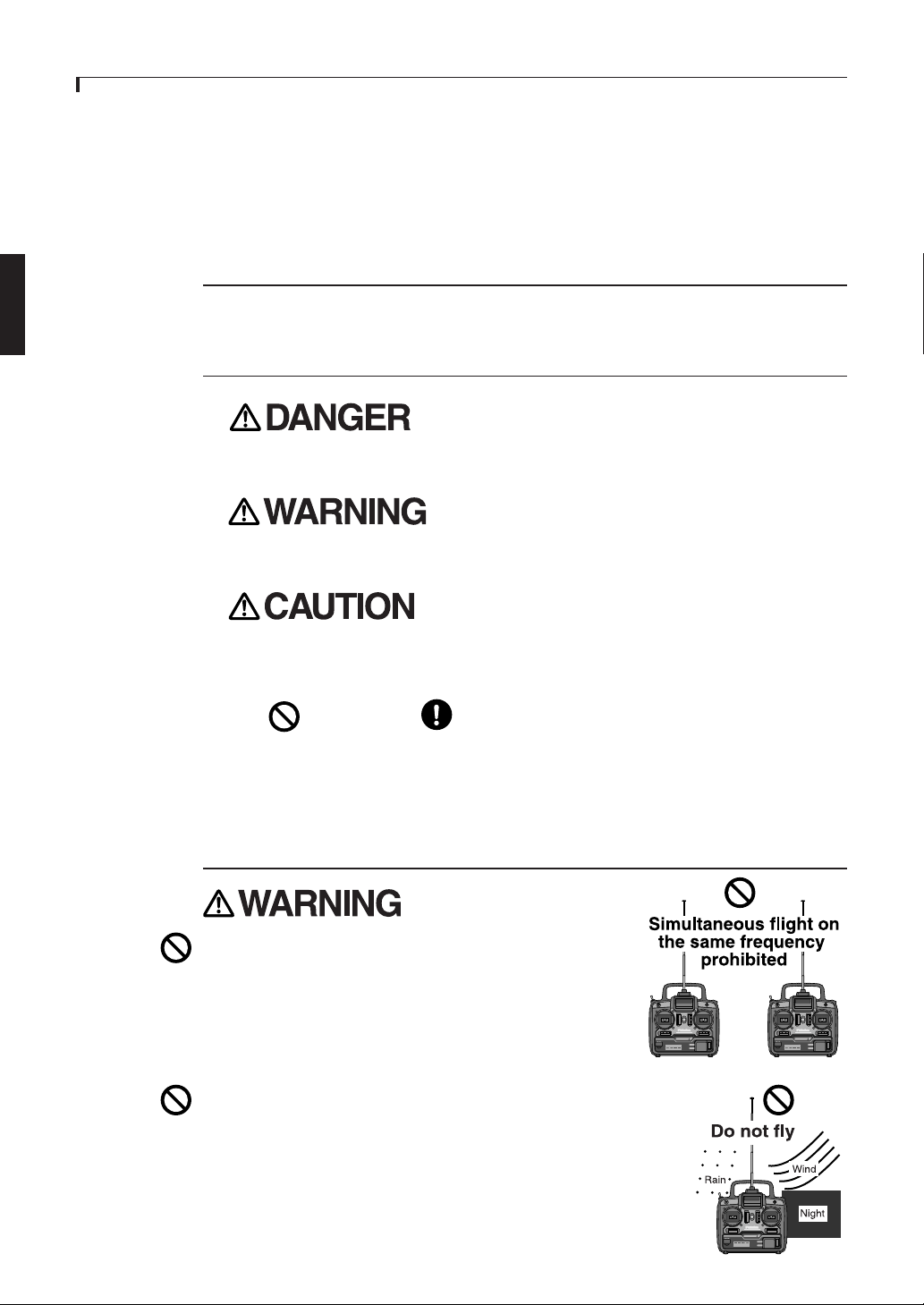
Do not fly simultaneously on the same frequency.
Interference may cause a crash.
Use of the same frequency will cause interference even if the
modulation method (AM, FM, PCM) is different.
Do not fly on rainy or windy days, or at night.
Water will penetrate into the transmitter and cause faulty operation,
or loss of control, and cause a crash.
Page 4
FOR SAFETY
Do not fly in the following places:
-Near other R/C flying fields (within about 3km)
-Near people on the ground, or objects in the air
-Near homes, schools, hospitals, or other places where there is a lot of people
-Near high tension lines, high structures, or communication facilities
Radiowave interference and obstructions may cause a crash. A crash caused by trouble in
the R/C set, or the model itself, may cause death or property damage.
Do not fly when you are tired, sick, or intoxicated.
Fatigue, illness, or intoxication will cause a loss of concentration or normal judgment and
result in operation errors and a crash.
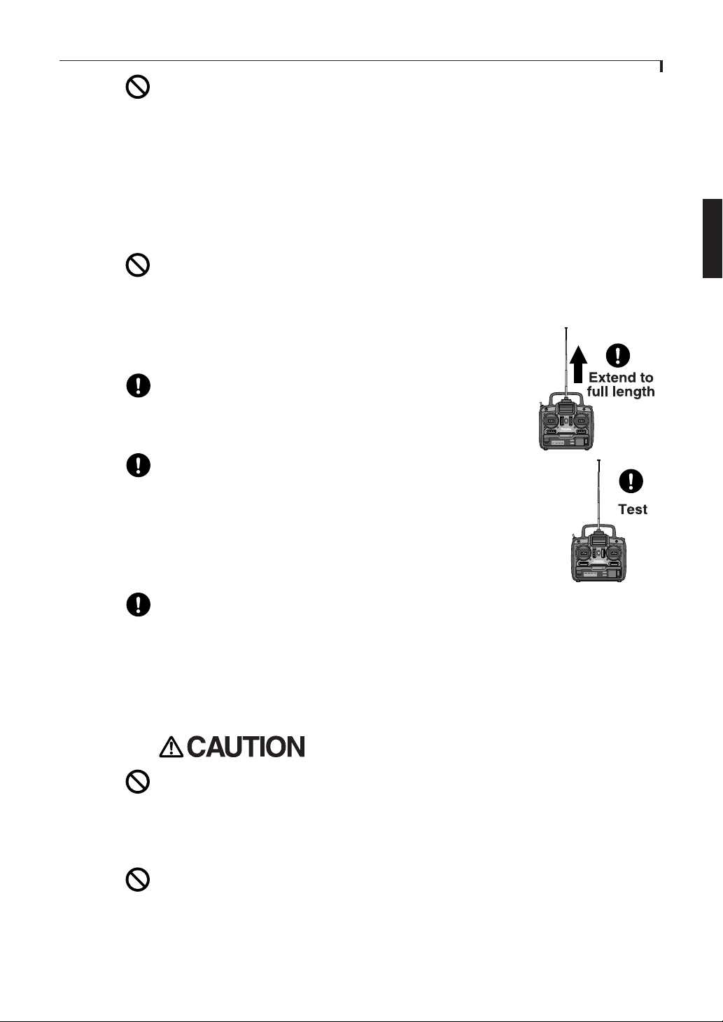
Extend the antenna to its full length.
If the antenna is too short, the effective range of the radiowaves
will become shorter.
5
Always test the digital proportional R/C set before use.
Any abnormality in the digital proportional R/C set, or model, may
cause a crash.
Before starting the engine, check that the direction of operation of each
servo matches the operation of its control stick. If a servo does not move
in the proper direction, or operation is abnormal, do not fly the plane.
Check that the transmitter antenna is not loose.
If the transmitter antenna comes off during use, control will be lost and the model will
crash.
When placing the transmitter on the ground during flight preparations, be sure that
the wind cannot knock it over.
If it is knocked over, the throttle stick may be pushed to full high and the engine will
race and create a dangerous situation.
Do not touch the engine, motor, and FET amp during and immediately after use.
They are hot and will cause a burn.
Page 5
FOR SAFETY
6
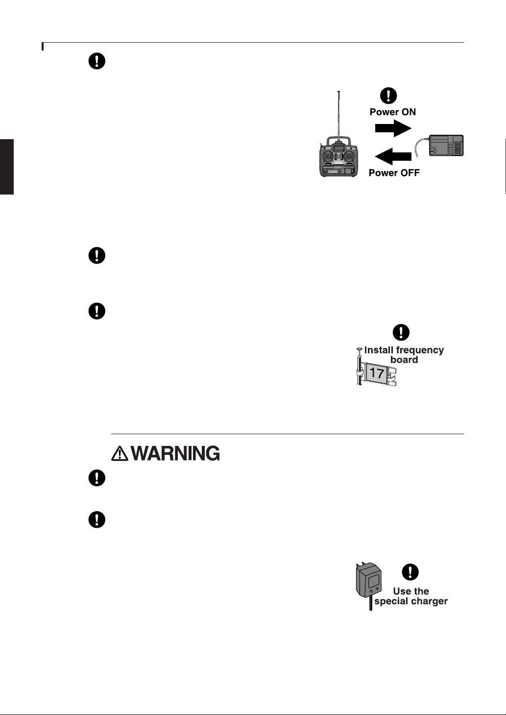
When turning on the power switch
After setting the transmitter throttle stick to maximum slow,
1. Turn on the transmitter power switch,
2. Then turn on the receiver power switch.
When turning off the power switch
After stopping the engine,
1. Turn off the receiver power switch,
2. Then turn off the transmitter power switch.
If the power switch is turned off in the opposite order, the engine may go to full throttle
unexpectedly and cause an injury.
Maximum slow: Direction in which the engine or motor runs at the slowest speed.
When adjusting the digital proportional R/C set, always stop the engine, except
when necessary.
If the engine suddenly goes to high speed, it may cause an injury.
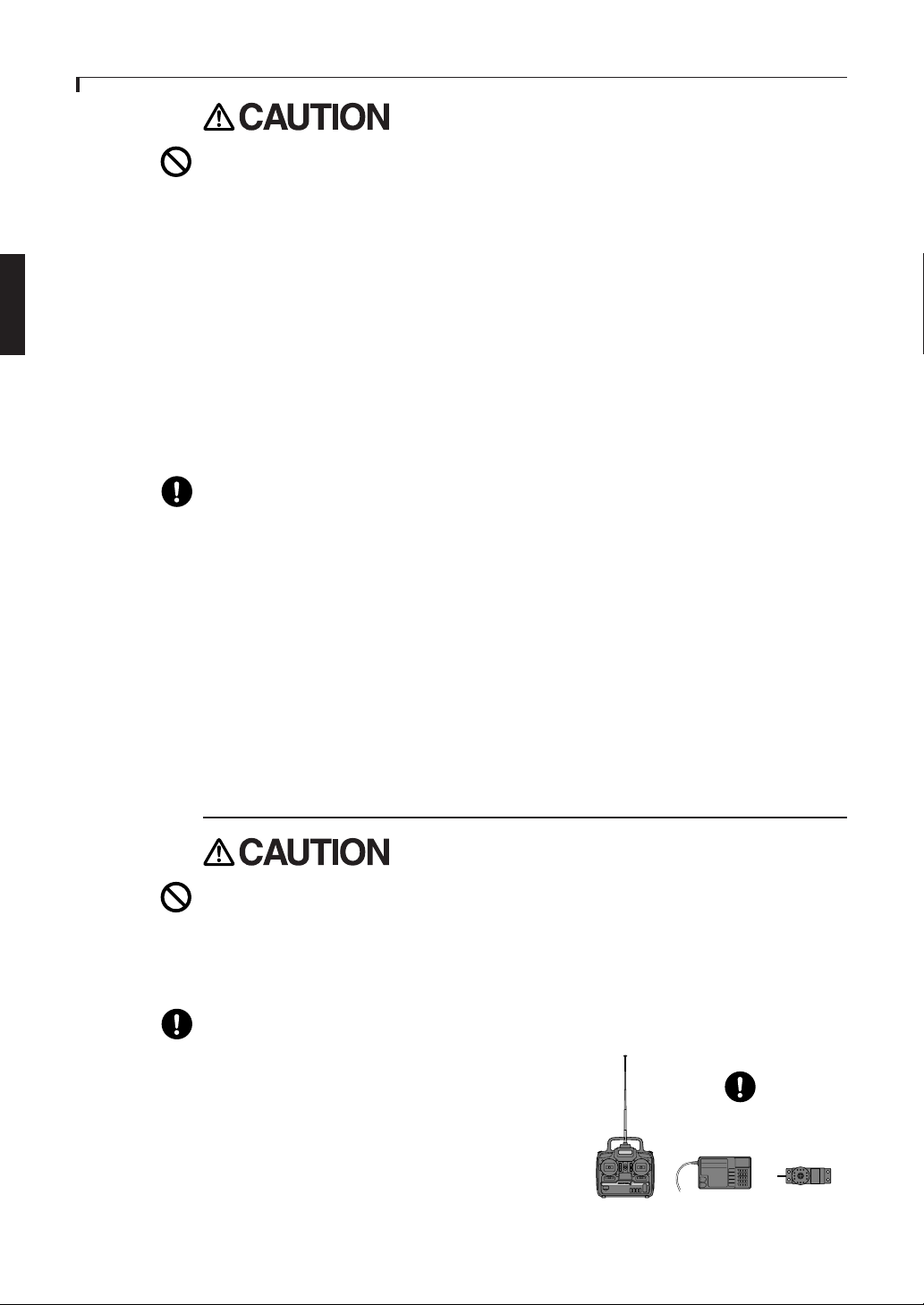
When flying, always install the frequency board to the transmitter antenna.
When the frequency was changed, also change the frequency board.
Nicd Battery Charging Precautions
Always charge the nicd battery before each flight.
If the battery goes dead during flight, the plane may crash.
Charge the digital proportional R/C nicd battery with the special charger, or digital
proportional R/C quick charger, sold separately.
Overcharging may cause burns, fire, injury, blindness, etc. due to overheating, breakage,
electrolyte leakage, etc.
Page 6
FOR SAFETY
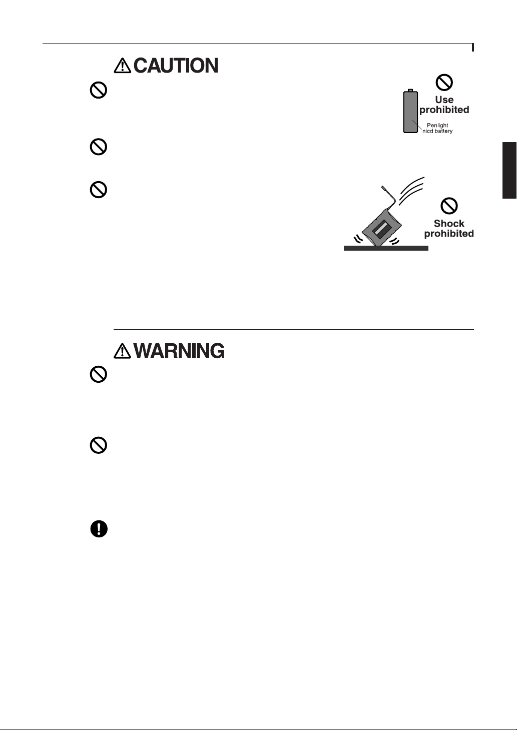
Do not use commercial nicd penlight batteries.
During quick charging, the battery holder contacts may overheat and
damage the equipment, or prevent charging.
Do not short the nicd battery connector terminals.
Shorting the terminals may cause sparking and overheating and result in burns or fire.
Do not drop or apply strong shock to nicd battery.
The battery may be shorted and cause overheating or
breakage and electrolyte leakage and result in burns or
damage by chemical mater.
Storage and Disposal Precautions
7
Do not leave the digital proportional R/C set, battery, model airplane, etc. within the
reach of small children.
Touching and operating the digital proportional R/C set, or licking the battery, may cause
injury or damage due to chemical matter.
Do not throw the nicd battery into a fire or heat the nicd battery. Also, do not
disassemble or rebuild the nicd battery.
Breakage, overheating, and electrolyte leakage may cause injury, burns, or blindness.
When not flying the model, store the digital proportional R/C set with the nicd
battery in the discharged state. Recharge the nicd battery before the next flight.
If a partially discharged nicd battery is recharged many times, its memory effect will
reduce the flight time substantially and may cause a crash, even if the battery is recharged.
Nicd Battery Electrolyte
The electrolyte in the nicd battery is a strong alkali and can cause blindness if it gets in
the eyes. If you get the electrolyte in your eyes, immediately wash your eyes with water
and see a doctor. If you get the electrolyte on your skin or clothes, it may cause a burn.
Immediately wash it off with water.
Page 7
FOR SAFETY
8
Do not store the digital proportional R/C set in the following places:
-Where it is very hot (104F or more) or very cold (-14F or less).
-Where the set will be exposed to direct sunlight.
-Where the humidity is high.
-Where there is strong vibration.
-Where it is dusty.
-Where there is steam and heat.
Storing the digital proportional R/C set in the places above may cause distortion and
trouble.
If the digital proportional R/C set will not be used for a long time, remove the nicd
batteries from the transmitter and the model and store them in a dry place.
If the batteries are left in the transmitter and model, the battery electrolyte may leak out
and degrade the performance and shorten the life of the transmitter and model.
Nicd Battery Recycling
Used nicd batteries are an important resource. Stick tape over the terminals and take the
used batteries to a nicd battery recycling center.
Other Precautions
Do not get fuel, waste oil, etc. on plastic parts.
The plastic may melt and fail to function.
Always use Genuine Futaba transmitter, receiver, servos, FET amp, nicd battery,
and other optional parts.
Futaba is not responsible for damage, etc. caused by
the use of parts other than Genuine Futaba parts.
Use the parts described in the instruction manual and
catalogs.
Use genuine parts
Page 8

BEFORE USE
Set Contents
After opening the carton, first check if the following items are provided.
The set contents depend on the type of set, and these are the standard.
BEFORE USE
9
Transmitter
Receiver
Servo
Receiver
Nicd Battery
/Battery holder
(not for U.S.A.)
T6YF
R127DF R116FB
or
S3003(x4)
Nicd Battery Battery holder
NR-4J
R2-BSS-B
Servo horn
Servo tray
Receiver Swich
Extension cord
Small screwdriver
FP-R116FB
(not for U.S.A.)
6/B
5
4
3
2
1
Charger
Frequency board
If the set contents are incomplete, or if you have any questions, please contact the dealer.
Page 9

10
ON
BEFORE USE
Name and Handling of Each Part
Transmitter T6YF (Front Panel)
Carrying handle
Landing gear switch
CH.5
Trainer switch
Elevator(Mode 1)
Throttle(Mode 2)
/Rudder stick
Elevator trim
lever(Mode 1)
Throttle trim
lever(Mode 2)
Crystal
GEAR
TRAINER
FUTABA FLIGHT COMFORT
HIGH
LOW
Rudder trim
lever
THROTTLE CONTROL
DIGITAL PROPORTIONAL R/C SYSTEM
SERVO FUNCTION
Neck strap
hook
Antenna
Voltage indicator
CH.6
FLAP
NARROW BAND TECHNOLOGY
THROTTLE
ATV
SERVO
REVERSER
POWER
Servo reversing switches
Throttle ATV trimmers
Flap knob
Throttle(Mode 1)
Elevator(Mode 2)
/Aileron stick
Throttle trim lever
(Mode 1)
Elevator trim lever
(Mode 2)
Aileron trim lever
Power switch
Power switch: Turns the trnsmitter on or off. In the upper position, the power is turned
on.
Voltage indicator: This is an expanded scale voltmeter. It is not calibrated in volts.
When the needle deflects to the boundary between the silver and red zones, recharge or
replace the battery. Do not operate the transmitter if the needle falls down to the red area.
Antenna: Never operate the transmitter without extending this antenna or you may create
interference to other modelers. This antenna is not intended to be removable.
Aileron, Elevator, Throttle and Rudder stick: Control each function. See page 14 for a
transmitter operation instruction.
Aileron, Elevator, Throttle and Rudder trim: Used to shift the neutral or idle position
of the each servo. As the throttle stick is moved forward towards the high throttle position, the throttle trim will have less effect.
Carrying handle: Provides an easy means of transporting the transmitter.
Neck strap hook: Clip the neck strap only to this hook when neck strap use is required.
Servo reversing switches: Switches that reverse the direction of operation of the servos.
The lower position is the normal side and the upper position is the reverse side.
<Channel display>
1 :Aileron (CH1)
2 :Elevator (CH2)
3 :Throttle (CH3)
4 :Rudder (CH4)
5 :Landing gear (CH5)
6 :Flap (CH6)
<Operating direction display>
REV :Reverse side
NOR :Normal side
Page 10

BEFORE USE
PUSH
Landing gear switch: Controls the raising and lowering of retractable landing gear. Not
all models will use this function.
Flap knob: Controls the flap servo(CH6).
Throttle ATV trimmer(LOW/HIGH): Used to adjust throttle
servo travel limits. Servo travel can be adjusted independently
in each direction.
Throttle servo
Trainer switch: Operates the instructor transmitter when using the trainer function. The
student transmitter can be operated only while this switching is being pressed.
11
Transmitter T6YF (Rear Panel/Side Panel)
Trainer jack
Charging jack
PUSH
Battery cover
Trainer jack: Connects the trainer cord when using the trainer function. The trainer
cord is sold separately. See page 19 for the trainer function operation instructions.
Battery cover: Use when replacing the battery. Slide the cover downward while pressing
the part marked "PUSH".
Charging jack: Charging jack when charging the transmitter nicd battery.
Page 11

12
BEFORE USE
Do not charge a dry battery.
A dry battery may be charged and cause overheating or breakage and electrolyte leakage
and result in burns or damage by chemical mater.
Charging the Nicd Battery
Never plug the special charger into an AC outlet other than specific voltage.
If the charger is plugged into an AC outlet other than specific voltage, overheating,
sparking, etc, may cause burns, fire, etc.
Use the special charger, or digital proportional R/C quick charger, sold separately
to charge the digital proportional R/C nicd battery.
Overcharging will cause burns, fire, injury, or blindness due to overheating, breakage,
electrolyte leakage, etc.
When not using the nicd battery charger, disconnect it from the AC outlet.
The transmitter and receiver nicd batteries scan be charged simultaneously or independently.
1 Connect the charger transmitter connector to the transmitter charging jack
and the charger receiver connector to the receiver servo nicd battery.
2 Connect the charger to an AC outlet.
3Check that the charging LED ilght.
4 At the end of charging, disconnect the charger from the AC outlet.
Page 12

Receiver R127DF
Output connector/Battery connector
"7": (Not used) (CH7)
"6": Flap servo (CH6)
Antenna
"5": Gear servo (CH5)
"4": Rudder servo (CH4)
"3": Throttle servo (CH3)
"2": Elevator servo (CH2)
"1": Aileron servo (CH1)
"B": Battery connector
Crystal: The crystal is replaced from the side of the receiver.
Receiver R116FB(not for U.S.A.)
Antenna
FP-R116FB
6/B
5
4
3
2
1
Output connector/Battery connector
"6": Flap servo (CH6)
"5": Gear servo (CH5)
"4": Rudder servo (CH4)
"3": Throttle servo (CH3)
"2": Elevator servo (CH2)
"1": Aileron servo (CH1)
BEFORE USE
13
Battery connector and
Output connector "6"
Crystal: The crystal is replaced from the rear of the receiver.
Servo S3003
To receiver
Servo horn
Mounting flange
Accessories: The following items are supplied with the set:
-Spare servo horn: Use to match the application.
-Servo mounting parts: Rubber bushing, grommet, wood screw
Page 13

14
BEFORE USE
Transmitter Operation and Movement of
Each Sesvo
Before making any adjustments, learn the operation of the transmitter and the movement
of each servo. (In the following descriptions, the transmitter is assumed to be in the
standby state.)
Aileron Operation
When the aileron stick is moved to the right, the right aileron is raised and the left aileron
is lowered, relative to the direction of flight, and the plane turns to the right. When the
aileron stick is moved to the left, the ailerons move in the opposite direction. To level the
plane, the aileron stick must be moved in the opposite direction. When the aileron stick is
tilted and held, the plane will roll.
Elevator Operation
When the elevator stick is pulled back, the tail elevator is raised and the tail of the plane
is forced down, the air flow applied to the wings is changed, the lifting force is increased,
and the plane climbs (UP operation). When the elevator stick is pushed forward, the
elevator is lowered, the tail of the plane is forced up, the air flow applied to the wings is
changed, the lifting force is decreased, and the plane dives (DOWN operation).
Throttle Operation
When the throttle stick is pulled back, the engine throttle lever arm moves to the SLOW
(low speed) side. When the throttle stick is pushed forward, the throttle lever arm moves
to the HIGH (high speed) side.
Rudder Operation
When the rudder stick is moved to the right, the rudder moves to the right and the nose
points to the right, relative to the direction of flight. When the rudder stick is moved to
the left, the rudder moves to the left and the nose points to the left and the direction of
travel of the plane changes.
Page 14

INSTALLATION AND ADJUSTMENT
INSTALLATION AND ADJUSTMENT
This section describes the installation method and adjustment method after installation
when installing the receiver, servos, etc. to the plane.
Connections
Connection examples are shown below. Make the connections matched to the type of set.
Connection Example(R127DF)
15
•Four servos are supplied as standard.
Connection Example(R116FB)(not for U.S.A.)
•Insert four batteries.
•When using five or more
servos,use the nicd battery sold
separately.
•Four servos are supplied as standard.
Page 15

16
INSTALLATION AND ADJUSTMENT
(Connector Connection)
Insert the receiver, servo, and battery connectors fully and firmly.
If vibration, etc. causes a connector to work loose during flight, the plane may crash.
(Receiver Vibrationproofing / Waterproofing)
Vibrationproof the receiver by wrapping it in sponge rubber or some such material.
If the receiver may get wet, waterproof it by placing it in a plastic bag.
If the receiver is subjected to strong vibration and shock, or gets wet, it may operate
erroneously and cause a crash.
(Receiver Antenna)
Do not cut or bundle the receiver antenna.
Also, do not bundle the antenna together
with the servo lead wires.
Cutting or bundling the receiver antenna will
lower the receiver sensitivity and shorten the
flight range and cause a crash.
Antenna installation: For aircraft, attach the
antenna to the top of the tail.
(Servo Throw)
Operate each servo horn over its full stroke and adjust so that the pushrod does not
bind or is not too loose.
Unreasonable force applied to the servo horn will adversely affect the servo and drain the
battery quickly.
(Servo Installation)
Install the servos to the servo mount, etc. through a rubber
bushing. Also install the servos so that the servo case does
not directly touch the servo mount or other parts of the
fuselage.
(Servo Horn Screw)
Use the horn set screw supplied with the servo.
If a long screw is used, the interior of the servo may be damaged.
Power Switch Installation
When installing a receiver power switch to the fuselage, cut a rectangular hole somewhat
larger than the full stroke of the switch knob and install the switch so it moves smoothly
from ON to OFF.
Also install the switch where it will not come into direct contact with engine oil, dust, etc.
Generally, install the switch to the fuselage at the side opposite the muffler exhaust.
Page 16

INSTALLATION AND ADJUSTMENT
Adjustments
The operating direction, neutral position, and steering angle of each servo are adjusted.
The basic linkage and adjustments of the fuselage conform to the fuselage design
drawings and kit instruction manual. Be sure that the center of gravity is at the
prescribed position.
Adjustment Procedure
Before making any adjustments, set all the SERVO REVERSER switches on the front of
the transmitter to the lower(NOR) position and set the both THROTTLE ATV
trimmers(LOW/HIGH) to the maximum ("10") point. (Set the switches and the trimmers
with a small screwdriver, etc.)
Turn on the transmitter and receiver power switches and make the following adjustments:
1 Check the direction of operation of each servo.
If a servo operates in the wrong direction, switch its SERVO REVERSER switch. (The direction of operation can be changed without
changing the linkage.) Note that the direction of the aileron servo is
easily mistaken. (See page 14 for a transmitter operation instruction.)
17
2 Check the aileron, elevator, and rudder neutral adjustment and left-right
(up-down) throw.
Perpendicular
When the throw is unsuitable (different from steering angle specified by the kit instruction manual), adjust it by changing the servo horn and each control surface horn rod .
3 Check the engine throttle (speed adjustment) linkage.
Change the servo horn installation position and hole position so that the throttle is opened
fully when the throttle stick is set to HIGH (forward) and is closed fully when the throttle
stick and throttle trim are set for maximum slow (backward position and lower position,
respectively).
4 After all the linkages have been connected, recheck the operating direction,
throw, etc.
Before flight, adjust the aircraft in accordance with the kit and engine instruction manuals.
5 Fly the plane and trim each servo.
Check that when trimmed to the center, the
servo horn is perpendicular to the servo and
Rod
check the neutral position of the fuselage
control surfaces (aileron, elevator, rudder, etc.).
If the neutral position has changed, reset it by
adjusting the length of the rod with the linkage
rod adjuster.
Page 17

USING OTHER FUNCTION
18
USING OTHER FUNCTIONS
Using the Frequency Board
1 Stick the band number seal to the
frequency board.
2 Install the frequency board to the
antenna.
Pass the frequency board over the small part of
the antenna and slide it to the large part.
Use side A or side B, depending on the
thickness of the antenna.
Cut off the unused side along the slot with
cutters, etc.
Non-slip Adjustable Lever Head
The length of the stick lever head can be adjusted.
1 Unlock lever heads A and B by turning them in the arrow directions.
2 Set the stick to the most comfortable length and lock the lever heads by
turning them in the opposite direction of the arrows.
Stick Lever Spring Tension Adjustment
The stick spring strength can be adjusted. The operating feel of the aileron, elevator, and
rudder sticks can be individually adjusted.
1 Remove the four transmitter rear case
screws and remove the rear case.
2 Adjust the spring strength by turning the
screw of the channel you want to adjust.
3 Close the rear case and tighten the four
screws.
Page 18

USING OTHER FUNCTION
PUSH
Trainer Function
The trainer function is a very effective way for training students. To use it, the special
trainer cord (sold separately) is necessary.
The special trainer cord can be connected to SKYSPORT4, SKYSPORT6, 7U series, 8U
series, and PCM1024Z series transmitters.
Never turn on the student transmitter power switch.
Turning on the power switch will cause interference and a crash.
Set the student and instructor transmitters to the same settings.
For example, if the direction of operation is reversed, control will be lost and the plane
will crash.
The opposite side can only use an FM (PPM) type transmitter.
If the modulation method is different, control is impossible.
Connection
Connect the student and instructor transmitters with the trainer cord.
19
Trainer code
(Sold separately)
Trainer jack
PUSH
Trainer jack
Operating Instructions
Instructor side: Turn on the power switch and extend the antenna to its full length.
When the trainer switch is not pressed, the instructor has control. When the trainer switch
is pressed, control is transferred to the student.
Student side: Never turn on the power switch.
Page 19

REFERENCE
20
REFERENCE
*Specifications and ratings are subject to change without prior notice.
Ratings
Transmitter T6YF
(2 sticks, 6 channels, FM transmitter)
Transmitting frequency: 29, 35, 36, 40, 41, 50,
60, 72, 75 MHz
Modulation method: FM(Frequency Modulation)
Power requirement: 12V(penlight battery x 8) or
9.6V nicd battery
Current drain: 180mA
Receiver R127DF
(7 channels, FM dual conversion receiver)
Receiving frequency: 50, 60, 72, 75 MHz
Intermediate frequency: 1st IF 10.7MHz, 2nd IF
455kHz
Power requirement: 6V (penlight battery x 4) or
4.8V nicd battery(common with servo)
Current drain: 10.0mA
Size: 64.3x35.8x21.0mm
Weight: 40.5g
Receiver R116FB(not for U.S.A.)
(6 channels, FM receiver)
Receiving frequency: 29, 35, 36, 40, 41, 60, 72
MHz
Intermediate frequency: 455kHz
Power requirement: 6V(penlight battery x 4) or
4.8V nicd battery(common with servo)
Current drain: 22mA
Size: 33.4x50.4x20.5mm
Weight: 30g
Servo S3003
(Standard servo)
Power requirement: 4.8V or 6V (common with
receiver)
Current drain: 8mA (idle)
Output torque: 3.2kg-cm (4.8V)
Operating speed: 0.23sec/60 degrees(4.8V)
Size: 40.4x19.8x36mm
Weight: 37.2g
Frequencies
The following frequencies and channel numbers may be used for aircraft and surface in
the United States:
72 MHz Band: (Aircraft only)
72.010 11 72.210 21 72.410 31 72.610 41 72.810 51
72.030 12 72.230 22 72.430 32 72.630 42 72.830 52
72.050 13 72.250 23 72.450 33 72.650 43 72.850 53
72.070 14 72.270 24 72.470 34 72.670 44 72.870 54
72.090 15 72.290 25 72.490 35 72.690 45 72.890 55
72.110 16 72.310 26 72.510 36 72.710 46 72.910 56
72.130 17 72.330 27 72.530 37 72.730 47 72.930 57
72.150 18 72.350 28 72.550 38 72.750 48 72.950 58
72.170 19 72.370 29 72.570 39 72.770 49 72.970 59
72.190 20 72.390 30 72.590 40 72.790 50 72.990 60
50 MHz Band: (Aircraft/car/boat -Fcc Amateur license required)
50.800 00
50.820 01
50.840 02
50.860 03
50.880 04
50.900 05
50.920 06
50.940 07
50.960 08
50.980 09
Page 20

REFERENCE
75 MHz Band: (car/boat only)
75.410 61 75.610 71 75.810 81
75.430 62 75.630 72 75.830 82
75.450 63 75.650 73 75.850 83
75.470 64 75.670 74 75.870 84
75.490 65 75.690 75 75.890 85
75.510 66 75.710 76 75.910 86
75.530 67 75.730 77 75.930 87
75.550 68 75.750 78 75.950 88
75.570 69 75.770 79 75.970 89
75.590 70 75.790 80 75.990 90
Troubleshooting
If your digital proportional R/C set does not operate, its range is short, it intermittently
stops operating, or it operates erroneously, take the action shown in the table below. If
this does not correct the trouble, please contact a Futaba dealer.
21
Check point
Transmitter/receiver battery
Transmitter antenna
Crystal
Connector connection
Receiver antenna
Servo linkage
Motor (electric motor plane)
Check item
Dead battery.
Incorrect loading.
Faulty contact connection.
Dirty contacts.
Loose.
Not extended to full length.
Disconnected.
Wrong band.
Different from specification.
Incorrect wiring.
Disconnection.
Close to other wiring.
Not cut?
Not bundled?
Binding or looseness
Noise countermeasures.
Action
Replace the battery. Charge the
nicd battery.
Reload the batteries in the
correct polarity.
If the contact spring is deformed,
correct it.
Wipe with a dry cloth.
Screw in.
Extend fully.
Push in.
Match transmitter/receiver band.
Replace with specified crystal.
Reinsert.
Push in.
Separate from other wiring.
Request repair.
Install in accordance with
instruction manual.
Adjust at the fuselage side.
Install a noise absorbing
capacitor.
Page 21

22
REFERENCE
Glossary
The following defines the symbols and terms used in this instruction manual.
Aileron (AIL.)
Control surface at the left and right sides of the
main wing of an aircraft. It usually controls
turning of the aircraft.
Channel
Represents the number of control systems. It
can also represent the number of servos that are
operated.
Down
Means down elevator. It is the direction in which
the trailing edge of the elevator is pointing down.
Elevator (ELE.)
Control surface that moves up and down on the
horizontal stabilizer of an aircraft. It usually
controls up and down.
Linkage
Mechanism that connects the servos and the
fuselage control surfaces.
Modulation method
Two modulation methods are used with radio
control: AM (Amplitude Modulation) and FM
(Frequency Modulation). Radio sets for aircraft
mainly use FM. Another method that encodes
and transmits the modulated signals is called
"PCM".
Neutral
Means the neutral position. It is the state in
which a transmitter stick returns to the center
when not operated.
Normal (NOR.)
For the servo reversing function, it is the normal
side. The opposite side is the reverse side.
Reverse (REV.)
With the servo reversing function, this is used to
mean the reverse side. The opposite side is the
normal side.
Rod
A bar that connects the servos and the fuselage
control surfaces.
Servo horn
A part that is installed to the shaft of a servo and
changes the rotating motion of the servo to
linear motion and transmits the linear motion to a
rod. Servo horns come in various shapes.
Servo mount
Fuselage base for installing a servo to the
fuselage.
Stick
Rod for operating the transmitter.
Throttle (THR.)
Part that controls the air mixture at the engine
intake. When opened (throttle high side), a large
air mixture is sucked in and the engine speed
increases. When closed (throttle low side), the
engine speed decreases.
Trim
A device that fine adjusts the neutral point of
each servo for safe flying. It is a mechanism that
corrects bad tendencies of the aircraft.
Up
Means up elevator. Direction in which the trailing
edge of the elevator is pointing up.
Rudder (RUD.)
Tail control surface that controls the direction of
the aircraft.
Page 22

REFERENCE
Repair Service
Before requesting repair, read this instruction manual again and recheck your system.
Should the problem continue, request repair service as follows:
Describe the problem in as much detail as possible and send it with a detailed packing list
together with the parts that require service.
• Symptom (Including when the problem occurred)
• System(Transmitter, Receiver, Servo's and model numbers)
• Model (Model name)
• Model Numbers and Quantity
• Your Name, Address, and Telephone Number.
• Dated Proof of Purchase (For Warranty Claims)
Please read the warranty card supplied with your system.
When requesting warranty, please send the card along with some type of dated proof of
purchase.
If you have any questions regarding this product, please consult your local hobby dealer
or contact the Futaba Service Center. The address and telephone number are listed below.
(For U.S.A.) (Telephone inquiries are accepted from 8:30 AM to 5:00 PM PST daily,
except on Saturday, Sunday and Holidays.)
Address(For U.S.A.)
Futaba Corp. of America
4 Studebaker
Irvine, CA 92618 (949) 455-9888
23
FUTABA CORPORATION
Makuhari Techno Garden Bldg., B6F 1-3 Nakase, Mihama-ku, Chiba 261-8555, Japan
Phone: (043) 296-5118 Facsimile: (043) 296-5124
©FUTABA CORPORATION 1998, 5
 Loading...