

Page 1
1. This product may be used for model airplane or surface use if on the correct frequency.
The product described in this manual is subject to regulations of the Ministry of
Radio/Telecommunications and is restricted under Japanese law to such purposes.
2. Exportation precautions
(a) When this product is exported from Japan, its use is to be approved by the Radio Law of
the country of destination.
(b) Use of this product with other than models may be restricted by Export and Trade
Control Regulations. An application for export approval must be submitted.
3. Modification, adjustment, and replacement of parts
Futaba is not responsible for unauthorized modification, adjustment, and replacement of
parts of this product.
This device complies with part 15 of the FCC rules. Operation is subject to the following
two conditions:
(1) This device may not cause harmful interference, and
(2) This device must accept any interference received, including interference that may cause
undesired operation.
The RBRCTM SEAL on the (easily removable) nickel-cadmium battery contained in Futaba
products indicates that Futaba Corporation of America is voluntarily participating in an
industry program to collect and recycle these batteries at the end of their useful lives, when
taken out of service within the United States. The RBRC
TM
program provides a convenient
alternative to placing used nickel-cadmium batteries into the trash or municipal waste which
is illegal in some areas.
Futaba Corporation of America's payments to RBRC
TM
makes it easy for you to return the
spent battery to Futaba for recycling purposes. You may also contact your local recycling
center for information on where to return the spent battery. Please call 1-800-8-BATTERY
for information on Ni-Cd battery recycling in your area. Futaba Corporation of America's
involvement in this program is part of its commitment to protecting our environment and
conserving natural resources.
NOTE: Our instruction manuals need to encourage our customers to return
spent batteries to Futaba or a local recycling center in order to keep a healthy
environment.
RBRC
TM
is a trademark of the Rechargeable Battery Recycling Corporation.
Pay special attention to the safety at the parts of this manual that are indicated by the
following marks.
:Procedures which may lead to a dangerous condition and cause death or
serious injury to the user if not carried out properly.
:Procedures which may lead to a dangerous condition or cause death or
serious injury to the user if not carried out properly, or p r ocedures where the probability of
superficial injury or physical damage is high.
:Procedures where the possibility of serious injury to the user is small, but
there is a danger of injury, or physical damage, if not carried out properly.
Symbol:
; Prohibited
; Mandatory
Page 2

I
NSTRUCTION
M
ANUAL
6XAs / 6XHs
FOR AIRCRAFT / HELICOPTERS
FM/PCM SYSTEM, 6 CHANNELS
Futaba Corporation
Page 3

INTRODUCTION
Thank you for purchasing a Futaba® 6XAs/6XHs series digital proportional R/C system.
This system is extremely versatile and may be used by both beginners and experts. In order for
you to make the best use of your system and to fly safely, please read this manual carefully. If
you have any difficulties while using your system, please consult the manual, your hobby dealer,
or Futaba. This product is to be used for sport and recreational flying of radio-control models
only. Futaba is not responsible for the results of use of this product by the customer or for any
alteration of this product, including modification or incorporation into other devices by third
parties. Modification will void any warranty and is done at owner’s risk..
Your T6XAs or T6XHs system includes the following components:
• T6XAs/T6XHs Transmitter. May be programmed for planes or helicopters, both with
special mixing function, 6 model memories. (Transmitting frequency: 29, 35, 36, 40, 41, 50,
60 or 72 Mhz band)
• R127DF or R116FB Receiver (FM system). R138DP or R148DP Receiver (PCM system).
(Receiving frequency: 29, 35, 36, 40, 41, 50, 60 or 72 Mhz band)
• Servos, S3003 with mounting hardware and servo arm assortment (or S148 Servo)
• Receiver battery (or Battery Box)
• Switch harness with charging jack
• Aileron extension cord (use to easily connect to an aileron servo in a detachable wing)
• AC battery charger
• Owner’s Manual
Owner’s Manual
This manual is not just a translation — it has been carefully written from scratch to be as
helpful to you, the new owner, as possible. There are many pages of setup procedures,
examples, explanations, and trimming instructions. If you feel that any corrections or
clarifications should be made, please jot them down on a piece of paper and send them to the
factory. The information contained in this manual is subject to change without notice due to
possible changes in manufacturing procedures or updates.
“Futaba” is a registered trademark of the Futaba Corporation of America.
Manual text copyright ©1996 by Don Edberg, Dynamic Modelling Co. All rights reserved
– ii –
Page 4

TABLE OF CONTENTS
Introduction to the T6XAs/T6XHs System.........................................................................1
ACRO Transmitter Controls and Switch Identification......................................................2
ACRO & HELI Transmitter Switch Functions ...................................................................2
Charging the Ni-Cd Battery.................................................................................................3
Operating With The Trainer Cord .......................................................................................3
Adjusting Stick Length & Tension......................................................................................4
Changing Transmitter Mode................................................................................................5
Reversing The Throttle Stick...............................................................................................5
ACRO Receiver and Servo Connections.............................................................................6
Radio Installation Precautions.............................................................................................7
Airplane Frequencies (U.S.A.) ............................................................................................9
Transmitter Displays and Programming Keys...................................................................10
Warning Displays ..............................................................................................................11
Safety Precautions (DO NOT operate without reading)....................................................12
AIRCRAFT FUNCTIONS INDEX (ACRO Menu) 13
Aircraft (ACRO) Functions Diagram................................................................................14
Aircraft Setup Example (Pattern model) ...........................................................................15
Pattern Aircraft Trimming Chart.......................................................................................22
ATV................Adjustable Travel Volume.........................................................................24
D/R ................Dual Rates..................................................................................................25
EXP...............Exponential Settings..................................................................................26
REV...............Servo Reverse............................................................................................27
STRM............Subtrim......................................................................................................27
FLPR.............Flaperon (combined flaps & ailerons).......................................................28
FLTR.............Flap trim.....................................................................................................29
ABRK ............Airbrake settings........................................................................................30
VTAL.............V-tail mixing..............................................................................................31
ELVN.............Elevon mixing (tailless models) ................................................................32
1->4...............Rudder Coupling........................................................................................33
6->2...............Flap -> Elevator mixing.............................................................................34
2->6...............Elevator -> Flap mixing.............................................................................35
PMX1, 2........Programmable Mixer #1, #2......................................................................35
F/S.................Failsafe function (only in PCM mode)......................................................37
PARA ............Parameter menu .........................................................................................38
REST.............Data Reset..................................................................................................38
– iii –
Page 5

DRSW........... Dual Rate Switch Select............................................................................39
ACRO........... Acrobatic model mode.............................................................................. 39
HELI..............Helicopter model mode.............................................................................39
MOD............. Modulation (FM/PPM or PCM)................................................................ 40
COPY ........... Data Copy ................................................................................................. 40
TMEM........... Trim Memory............................................................................................ 41
MODL........... Model select.............................................................................................. 42
HELICOPTER SECTION INDEX 43
Helicopter (HELI) Functions Index.................................................................................. 43
Helicopter Function Menu Diagram................................................................................. 43
Helicopter Transmitter Controls and Switch Identification..............................................44
Helicopter Setup Instructions............................................................................................ 45
Helicopter Trimming Chart............................................................................................... 48
PI-N, I, H...... Pitch Rate (Normal, Idle-Up, Hovering)................................................... 49
HV-T ............. Hovering Throttle...................................................................................... 49
IDLE.............. Idle-Up function........................................................................................ 50
HOLD............ Throttle Hold............................................................................................. 51
REVO ........... Revolution mixing..................................................................................... 51
R-OF............. Rudder Offset............................................................................................ 52
HV-P............. Hovering Pitch .......................................................................................... 53
SWSH........... Swashplate Type & AFR .......................................................................... 53
Glossary............................................................................................................................ 55
Data Recording Sheets: ACRO, HELI.......................................................................... 56
Factory Repair Service................................................................................................... 57
– iv –
Page 6

Introduction to the 6XAs/6XHs Systems
TRANSMITTER
The versatile T6XAs/T6XHs
PCM1024 multi-function 6-channel
transmitter may be used with any Futaba
FM/PPM receiver! In addition, your system
will work with Futaba PCM1024 receivers
when you select the built-in PCM
transmission option. The liquid-crystal
display panel allows rapid data input into its
easy-to-read LCD display.
The T6XAs/T6XHs system comes
complete with programming for ACRO
(aircraft) and HELI (helicopter) mixing and
can accommodate virtually any model
configuration. The compact, ergonomicallydesigned transmitter holds completely
independent memories for six different
models.
The T6XAs/T6XHs features a new
stick design which provides an improved
feel. The sticks’ length and tension may be
adjusted. Switches are provided for dual
rate (D/R), programmable mixers (PMX),
and other functions. For those learning to
fly, the transmitter has “buddy-box”
capability where a second transmitter may
be used by an experienced pilot as an
instructor. [The trainer cord is sold
separately.]
Standard programming features
include servo reversing for all channels,
ATV on all channels, dual rates,
exponential, and fail safe on all channels
(PCM transmission only). In addition, the
T6XAs/T6XHs features a number of handy
mixing features applicable to all types of
flying models. For aircraft, the extensive
preprogrammed mixing features include:
flaperon, V-tail, elevon, airbrake, elevator ->
flap, and flap -> elevator. Helicopter
features include hovering pitch and throttle,
revolution mixing, swashplate type
selection, and rudder offset. [Note: the
T6XAs/T6XHs may be used for sailplanes.
For these we recommend Futaba’s System 8,
which contains extensive sailplane
programming.]
Transmitter Specifications:
Operating system: 2-stick, 6 channels,
PCM1024 system
Modulation: FM/PPM or PCM, switchable
Power supply: 9.6V Ni-Cd battery
Current drain: 250mA
RECEIVER
The R127DF seven-channel receiver
included with your system is a compact
high-sensitivity narrow-band unit, providing
superior range and performance.
Receiver Specifications (FP-
R127DF)
Type: FM, Dual conversion
Intermediate frequencies: 455kHz, 10.7MHz
Power requirement: 4.8V or 6V Ni-Cd battery
Current drain: 14mA @ 4.8V
Size: 1.39x2.52x0.82” (35.3x64.0x20.8mm)
Weight: 1.5oz (42.5g)
Receiver Battery
4-cell NR-4J (NR-4RB for heli version)
Capacity: 500mAH (1,000mAH for NR-4RB)
Weight: 3.3oz/94g (3.9oz/111g for NR-4RB)
SERVO SPECIFICATIONS
Servo type: S3003 (Standard)
Control system: Pulse width control, 1.52ms
neutral
Power requirement: 4.8V (from receiver)
Output torque: 44.4oz-in (3.2kg-cm)
Operating speed: 0.23sec/60°
Size: 1.59x0.78x1.41” (40.4x19.8x36mm)
Weight: 1.3oz (37.2g)
*Specifications and ratings are subject to change without notice.
– 1 –
Page 7

– 2 –
Page 8
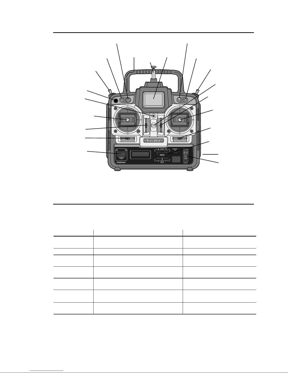
TRANSMITTER CONTROLS – AIRCRAFT (T6XAs System)
FUTABAFLIGHTCOMFORT NARROWBANDTECHNOLOGY
Elevator Dual
Rate Switch (A)
Flap Knob (Ch. 6)
Aileron Dual
Rate Switch (C)
Airbrake Switch (B)
Antenna
Landing Gear
Switch (Ch. 5,
Sw. E)
Elev -> Flap
Mixing Switch
(D)
Carrying
Handle
Liquid-Crystal
Display
Trainer Pushbutton Switch
ON indicator
light
Rudder / Throttle
Stick
Throttle Trim
Rudder Trim
Crystal Cover
Neckstrap Hook
Elevator Trim Lever
Aileron / Elevator
Stick
Aileron Trim Lever
Programming Keys
Charging Jack
On-Off Switch
X'TAL
T6XH
COMPUTER RADIO
PCM / PPM SELECTABLE
Fun to Fly
This figure shows the default assignments for a Mode 2 aircraft system as supplied by the factory.
SWITCH ASSIGNMENT TABLE
The functions activated by the switches and knobs for a Mode 2 transmitter are shown in the
table below. Note that some of the functions will not operate until activated in the mixing
menus. For a Mode 1 transmitter, elevator and throttle are reversed, as are switches D and E.
Switch / Knob ACRO HELI
Switch A
Up = Elevator Dual Rate 1;
Down = PMX1 & PMX2 on; Elev D/R 2
Up = Elevator Dual Rate 1;
Down = Elev D/R 2
Switch B
Down = Airbrake on Gyro sensitivity (if desired)
Switch C
Up = Aileron Dual Rate 1
Down = Aileron Dual Rate 2
Up = Aileron Dual Rate 1
Down = Aileron Dual Rate 2
Switch D
Forward = 2 -> 6 (Elev -> Flap) on Forward = Throttle Hold on, and
REVO off
Switch E
Landing Gear Forward = Idle-up on, Rudder
offset on, and REVO off
Switch F
(Push-button)
Trainer Trainer
CH6 knob
Flap or Flap trim if flaperon function
(FLPR) on
Hovering Pitch
– 3 –
Page 9

CHARGING THE Ni-Cd BATTERIES
1. Connect the transmitter charging cord into the charging socket (on the right of the case,
when facing the front) and airborne Ni-Cd batteries to the receiver connector on the
charger.
2. Plug the charger into a wall socket.
3. The charger’s LEDs should light, indicating charging current is flowing. The batteries
should be left on charge for about 15 hours.
Only charge the batteries with the charger supplied with
your system. The use of a fast charger may damage the batteries by overheating and
dramatically reduce their lifetime.
You should fully discharge your system’s batteries
periodically to prevent a condition called “memory.” For example,
if you only make two flights each session, or you regularly use only a small amount of the
batteries’ capacity, the memory effect can reduce the actual capacity even if the battery is
fully charged. You can cycle your batteries with a commercial cycling unit, or by leaving the
system on and exercising the servos by moving the transmitter sticks. Cycling should be
done every one to two months, even during the winter or periods of long storage. Keep track
of the batteries’ capacity during cycling; if there is a noticeable change, you may need to
replace the batteries.
NOTE: If you need to remove or replace the transmitter battery, do not pull on its wires to
remove it. Instead, gently pull on the connector’s plastic housing where it plugs in to the
transmitter.
Operating With The Trainer Cord
An optional training cord is available from your dealer. The cord may be used to help
a beginning pilot learn to fly easily by allowing a second transmitter, operated by an
experienced instructor, to be connected to this system. The instructor may override the
beginning pilot at any time to bring the model back under safe control. For training, the
T6XAs/ T6XHs transmitter may be connected to another T6XAs/XHs system, as well as to
any 4VF, 6VA Skysport, 6XA, Super 7, System 8, or 9Z series transmitter.
To use the trainer cord:
1. Set up both the student’s and instructor’s transmitters to have identical trim and control
motions. If the instructor’s transmitter is on a different frequency than the student’s, use
the student’s as the master transmitter and the other as the student’s.
– 4 –
Page 10

2. Set the student transmitter modulation mode to PPM. Collapse the student’s antenna, and
fully extend the instructor’s antenna. Remove the RF module from the transmitter held
by the student (if it is a module-type transmitter).
3. Plug one end of the trainer cord into each
transmitter, with power switched off. The trainer
jack is in the center of the rear face of the
transmitter. Do not force, the connector is keyed.
4. Turn on the instructor’s transmitter. DO NOT turn
on the student transmitter power. Move the controls
on the instructor’s transmitter, and verify each
control moves the proper direction. Now verify that
the student’s trims and control travels match the instructor’s by using the trainer button
and switching back and forth while leaving the control sticks and trims alone, then
moving the control sticks.
5. The instructor’s transmitter has normal control over the model unless the trainer button is
pushed, when the student’s has control. If control is lost, the instructor should release the
trainer button and resume controlling the model.
OTHER T6XAS/XHS ADJUSTMENTS
Adjustable length non-slip control sticks
You may change the length of the
control sticks to make your transmitter more
comfortable to hold and operate. To lengthen
or shorten your transmitter’s sticks, first unlock
the stick tip by holding locking piece B and turning stick tip A counterclockwise. Next,
move the locking piece B up or down (to lengthen or shorten). When the length feels
comfortable, lock the position by turning locking piece B counterclockwise.
Stick lever tension adjustment
You may adjust the stick tension of your
sticks to provide the “feel” that you like for
flying. To adjust your springs, you’ll have to
remove the rear case of the transmitter. Using a
screwdriver, remove the four screws that hold
the transmitter’s rear cover into position, and put them in a safe place. Gently ease off the
transmitter’s rear cover. You may wish to unplug the battery wire. Carefully rotate the rear
of the case you you have access to the rear of the sticks. Now you’ll see the view shown.
Using a small screwdriver, rotate the adjusting screw for each stick for the desired
spring tension. The tension increases when the adjusting screw is turned clockwise, and
– 5 –
Page 11
decreases for counterclockwise motion. When you are satisfied with the spring tensions, you
may close the transmitter. Very carefully reinstall the rear cover. When the cover is properly
in place, tighten the four screws.
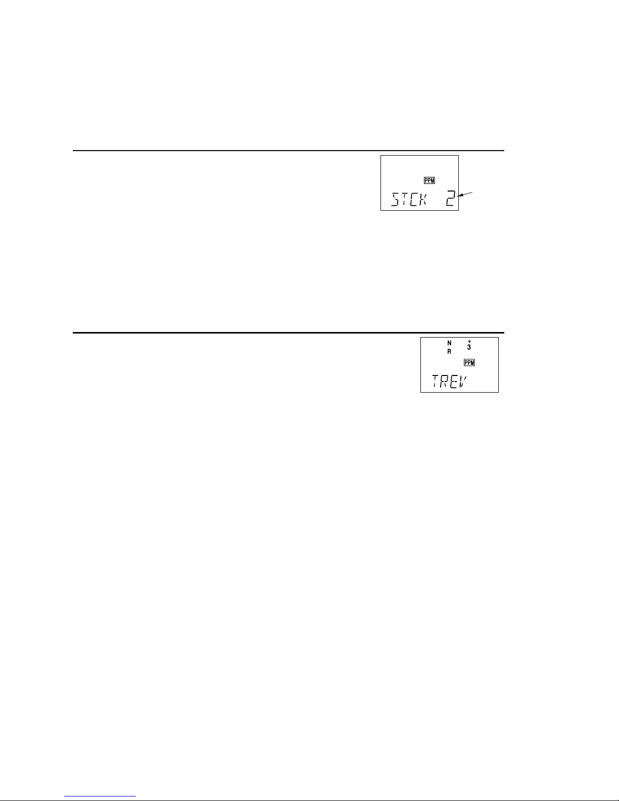
Changing the T6XAs/Hs transmitter’s mode
flashing
If you wish to change the mode of the transmitter, say
from mode 1 to mode 2, turn on the transmitter holding the two
MODE buttons down. You’ll see a display “STCK X,” where X
is a number representing the current transmitter mode. Press the
plus (+) or minus (–) DATA INPUT key to change the mode number as desired. You’ll see the
effect of you changes when you next turn on your transmitter. In some cases, you’ll have to
swap the throttle detent mechanism with the elevator centering mechanism. This can be done
by Futaba.
Reversing the throttle stick’s action
If for some reason you wish to reverse the action of the throttle
stick (for example, to get throttle trim at the top of the stick’s travel), you
may reverse it by turning on the transmitter holding the two MODE
buttons down, then pressing either of the MODE buttons to get to the
TREV menu. You may then use the (+) or (–) keys to switch between normal and reversed
functioning.
– 6 –
Page 12

RECEIVER AND SERVO CONNECTIONS
Receiver output
channel
Aircraft
(ACRO)
Helicopter
(HELI)
1 Right aileron or
combined right flap + aileron
*
or
right elevon
†
(tailless)
Aileron
2 Elevator or
V-tail
‡
right side or
left elevon
†
(tailless)
Elevator
3 Throttle Throttle
4 Rudder or
V-tail
‡
left side
Rudder
5 Landing Gear Gyro sensitivity
6 Flap or
combined Left flap + aileron
*
Pitch
Multiple entries indicate that the servo function varies with the selected programming (*=FLPR mode,
†
=ELVN mode, ‡=VTAL mode). Outputs with no mixing functions are shown first.
The diagram below shows the default servo connections for a model using the ACRO
mode (only three or four servos are included in the T6XAs system). Two possible model
formats are shown on the ACRO contents page. Suggested helicopter connections are given
within the helicopter setup example.
– 7 –
Page 13
RADIO INSTALLATION
While you are installing the battery, receiver, and servos into your model’s fuselage, please
pay attention to the following guidelines:
Servo Notes
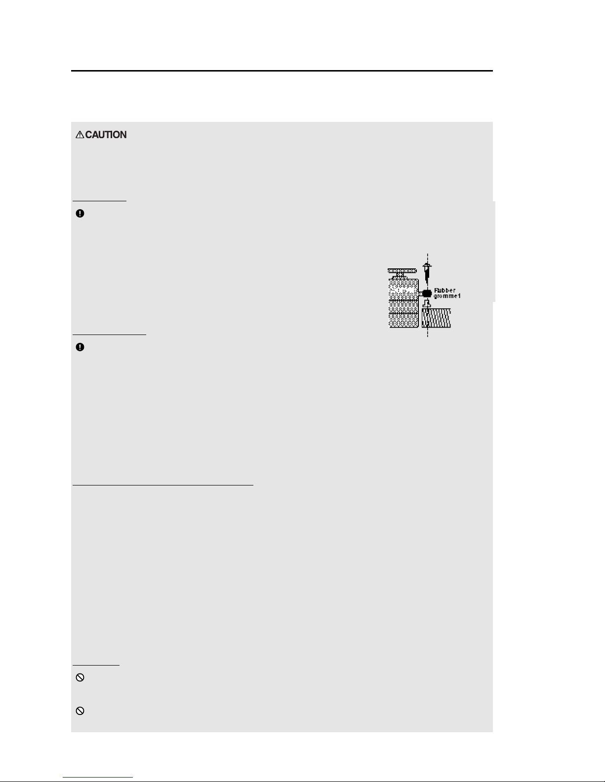
Mounting
Use the supplied rubber grommets when you mount each servo.
Be sure not to overtighten the screws. If any portion of the servo case
directly contacts the fuselage or the servo rails, the rubber grommets will not attenuate
vibration, which can cause mechanical wear and servo failure.
Servo Throw
Once you have installed the servos, operate each one over
its full travel and check that the pushrod and output arms do
not bind or collide with each other, even at extreme trim
settings. Check to see that each control linkage does not require undue force to move (if
you hear a servo buzzing when there is no transmitter control motion, most likely there is too
much friction in the control or pushrod). Even though the servo will tolerate loads like this,
they will drain the battery pack much more rapidly.
Switch Harness Installation
When you are ready to install the switch harness, remove the switch cover and use it as a
template to cut screw holes and a rectangular hole slightly larger than the full stroke of the
switch. Choose a switch location on the opposite side of the fuselage from the engine
exhaust, and choose a location where it can’t be inadvertently turned on or off during
handling or storage. Install the switch so that it moves without restriction and “snaps” from
ON to OFF and vice versa.
Receiver Notes
Antenna
DO NOT cut or coil the receiver antenna wire. It is normal for the
receiver antenna to be longer than the fuselage.
DO NOT cut it or fold it back on itself – cutting or folding changes
the electrical length of the antenna and may reduce range. Secure the antenna to the top of
– 8 –
Page 14

the vertical fin or the tailboom, and let the excess length trail behind the aircraft (be sure it
cannot tangle with the tail rotor on a helicopter).
You may run the antenna inside of a non-metallic housing within the fuselage, but range may
suffer if the antenna is located near metal pushrods or cables. Be sure to perform a range
check before flying. With the antenna collapsed, you should be able to walk 20 - 30 paces
from the model without losing control or seeing “jitter” in the servos.
Connectors
When you insert servo or battery connectors into the
receiver, note that each plastic housing has an alignment tab.
Be sure the alignment tab is oriented properly before
inserting the connector. To remove a connector from the
receiver, pull on the connector housing rather than the wires.
Using The Aileron Extension
If your aileron servo (or others) are located too far away
to plug into the receiver, use an aileron extension cord to
extend the length of the servo lead. Additional extension cords of varying
lengths are available from your hobby dealer or Futaba.
Vibration and Waterproofing
The receiver contains precision electronic parts. Be sure to avoid vibration, shock, and
temperature extremes.
For protection, wrap the receiver in foam rubber or other
vibration-absorbing materials. It’s also a good idea to waterproof the receiver
by placing it in a plastic bag and securing the open end of the bag with a rubber band before
wrapping it with foam. If you accidentally get moisture inside the receiver, you may
experience intermittent operation or a crash.
– 9 –
Page 15

Airplane Frequencies
The following frequencies and channel numbers may be used for flying aircraft in the U.S.:
72 MHz band
Ch. No. MHz 36 72.510
12 72.030 37 72.530
13 72.050 38 72.550
14 72.070 39 72.570
15 72.090 40 72.590
16 72.110 41 72.610
17 72.130 42 72.630
18 72.150 43 72.650
19 72.170 44 72.670
20 72.190 45 72.690
21 72.210 46 72.710
22 72.230 47 72.730
23 72.250 48 72.750
24 72.270 49 72.770
25 72.290 50 72.790
26 72.310 51 72.810
27 72.330 52 72.830
28 72.350 53 72.850
29 72.370 54 72.870
30 72.390 55 72.890
31 72.410 56 72.910
32 72.430 57 72.930
33 72.450 58 72.950
34 72.470 59 72.970
35 72.490 60 72.990
Installing your frequency number
indicator:
It’s very important that you display
your transmitting channel number at all times.
To install your indicator, peel off the channel
number’s backing sheet, and carefully stick
the numbers to both sides of the number
holder. Now you can snap the number holder
onto the lower portion of the antenna as
shown in the figure – use the clip that fits
more snugly on your antenna. You may wish
to cut off the other, unused clip on the
indicator.
– 10 –
Page 16
TRANSMITTER DISPLAYS & BUTTONS
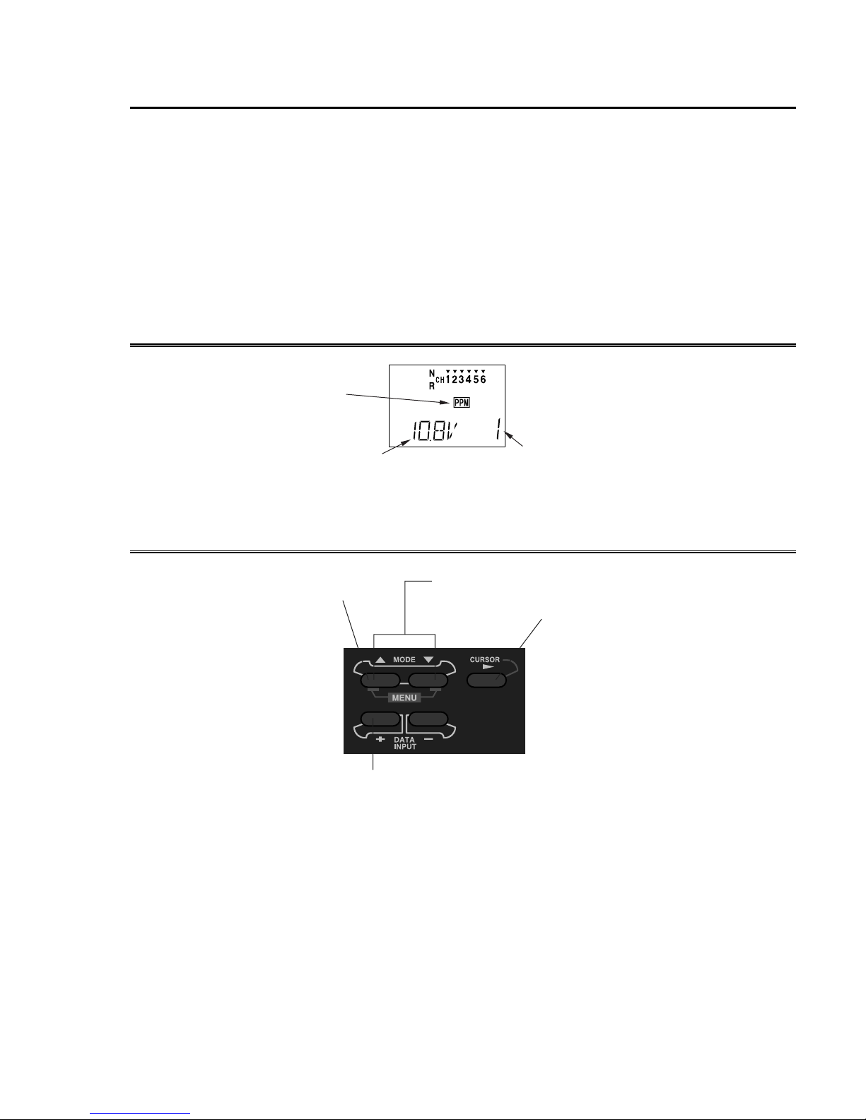
When you first turn on your transmitter, the screen shown below appears on the LCD
display. Before flying, or even starting the engine, BE SURE that the model number appearing
in the lower right of the display matches the model that you are about to fly! If you don’t, servos
may be reversed, and travels and trims will be wrong, leading to an immediate crash. (If you
have trouble remembering which model memory to use, write them on a small piece of tape
affixed to the front of the transmitter.)
Startup Screen (appears when system is first turned on)
Modulation
indicator
PPM shown
Edit keys
Battery voltage
(Alarm goes off at 8.5V)
MODE keys - use to
select desired function
while programming
DATA INPUT keys - use
these to input numbers or
settings
Current model memory
Model 1 shown
Press these two
keys to enter the
programming
menu
CURSOR key - use to
step through menu and
select item to be set or
changed in the screen
– 11 –
Page 17
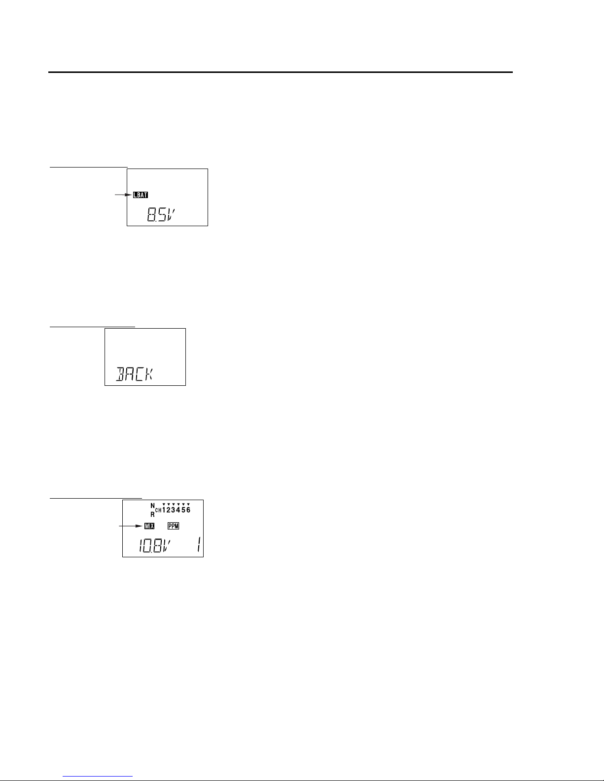
WARNING DISPLAYS
Your transmitter is designed to warn you about several potential problems that may occur,
including low battery voltage and switching on with mixing functions active. Each display has a
unique sound associated with it, as described below.
Low battery
The LOW BATTERY warning is displayed
flashing
when the transmitter battery voltage drops below
Warning sound: Beep beep beep —
(beeping does not stop
until transmitter is
turned off)
Backup error
Warning sound: Beep beep beep beep
(repeated)
Mixer warning
8.5V.
LAND YOUR MODEL AS SOON AS
POSSIBLE BEFORE LOSS OF CONTROL
DUE TO A DEAD BATTERY.
The BACKUP ERROR warning occurs when
the transmitter memory is lost for any reason. If
this occurs, all of the data will be reset when the
power is turned on again.
DO NOT FLY when this message is
displayed – all programming has been erased
and is not available. Return your transmitter
to Futaba for service.
flashing
Warning sound: beep beep beep pause
(repeated)
The MIXER warning is displayed to alert you
whenever you turn on the transmitter with any of
the mixing switches active. This warning will
disappear when the offending switch or control is
deactivated. At power-up, warnings will be
issued for the following switches:
ACRO: Airbrake
HELI: Throttle hold, idle-up
– 12 –
Page 18

Flying Safety
To ensure the safety of yourself and others, please observe the following precautions:
Ni-cd Battery
Charge the Batteries! Don't forget to recharge the batteries before each flying session. A battery low
in charge will soon die, causing loss of control and a crash. Plug in the charger that comes in this system
and hook up the transmitter and airborne batteries the day before a planned flying session. When you
begin your flying session, keep track of how long the system’s been used, and monitor the transmitter’s
voltage display. Quit flying long before your batteries become low.
On-field charging of your batteries with a field charger is not recommended. A fast-charger may
overcharge the Ni-Cd batteries, causing overheating and a premature failure.
Flying field
We recommend that you fly at a recognized model airplane flying field. You can find model clubs
and fields by asking your nearest hobby dealer, or contacting the Academy of Model Aeronautics.
Always pay particular attention to the flying field’s rules, as well as the presence and location of
spectators, the wind direction, and any obstacles on the field. Be very careful flying in areas near power
lines, tall buildings, or communication facilities as there may be radio interference in their vicinity. If
you must fly at a site that is not a club field, be sure there are no other modelers flying within a two-mile
range, or you may lose control of your aircraft.
Once you arrive at the flying field …
Before flying, be sure that the frequency you intend to fly with is not in use, and secure any
frequency control device (pin, tag, etc.) for that frequency before turning on your transmitter. Never
believe that it’s possible to fly two or more models on the same frequency at the same time. Even though
there are different types of modulation (AM, FM, PCM), only one model may be flown on a single
frequency.
When you are ready to fly your model, position the throttle stick to its low speed position, or do
whatever is necessary to command your motor NOT to run. Then, you may turn on the transmitter power
followed by the receiver power. When you have finished flying, begin by turning off the receiver power,
then turn off the transmitter power. If you do not follow these procedures, you may damage your servos
or control surfaces, flood your motor, or in the case of electric-powered models, the motor may
unexpectedly turn on and cause a severe injury.
Before starting the engine, fully retract the transmitter antenna, power up the transmitter and receiver,
and check to be sure that the servos follow the movement of the sticks. If a servo operates abnormally,
don’t attempt to fly until you determine the cause of the problem. We recommend that you range-check
your system before each flying session. Have an observer verify that the system works with the
transmitter about 30 paces away with the transmitter antenna collapsed. Finally, before starting the
engine, be sure to check that the transmitter model memory is correct for the chosen model, and (for PCM
receivers only) that the fail safe system functions properly when the transmitter is shut off.
While you’re getting ready to fly, if you place your transmitter on the ground, be sure that the wind
won’t tip it over. If it is knocked over, the throttle stick may accidentally move causing the engine to race
unexpectedly.
Before taxiing, be sure to extend the transmitter antenna to its full length. A collapsed antenna will
reduce your flying range and may cause a loss of control. It is a good idea to avoid pointing the
transmitter antenna directly at the model at all times, since the signal is weakest in that direction.
Don’t fly in the rain!
Water or moisture may enter the transmitter through the antenna or stick openings and cause erratic
operation or loss of control. If you must fly in wet weather during a contest, be sure to cover your
transmitter with a plastic bag or waterproof barrier.
– 13 –
Page 19

AIRCRAFT (ACRO) MENU FUNCTIONS
*Pages 14 to 42 describe the Basic Menu functions for fixed-wing aircraft, provide a
detailed setup example, and then describe the functions individually. Helicopter
functions may be found in the following section, pages 43 to 54.
Map of ACRO Menu Functions .................................................. 14
Aircraft Setup Example ............................................................... 15
Pattern Aircraft Trimming Chart................................................. 22
ATV............. Adjustable Travel Volume.................................... 24
D/R............... Dual Rates............................................................. 25
EXP Exponential Settings.................................................................... 26
REV ............. Servo Reverse ....................................................... 27
STRM .......... Subtrim.................................................................. 27
FLPR............ Flaperon (combined flaps & ailerons) .................. 28
FLTR............ Flap trim................................................................ 29
ABRK .......... Airbrake settings ................................................... 30
VTAL........... V-tail mixing......................................................... 31
ELVN........... Elevon mixing (tailless models)............................ 32
1 -> 4............ Rudder Coupling................................................... 33
6 -> 2............ Flap -> Elevator mixing........................................ 34
2 -> 6............ Elevator -> Flap mixing........................................ 35
PMX1, 2....... Programmable Mixer #1 & #2 .............................. 35
F/S................ Failsafe function (only in PCM mode) ................. 37
PARA........... Parameter menu..................................................... 38
RSET............ Trim Reset............................................................. 38
DRSW.......... Dual Rate Switch Select........................................ 39
ACRO .......... Acrobatic model mode.......................................... 39
HELI ............ Helicopter model mode......................................... 39
MOD............ Modulation (FM/PPM or PCM)............................ 40
COPY........... Data Copy ............................................................. 40
TMEM ......... Trim Memory........................................................ 41
MODL.......... Model select .......................................................... 42
– 14 –
Page 20
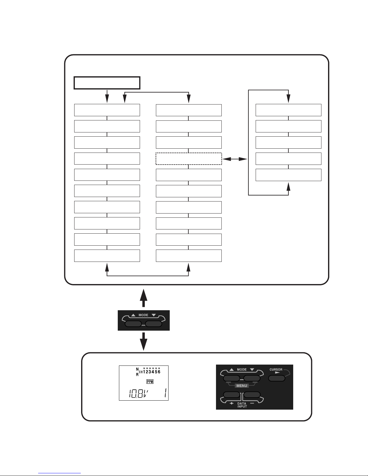
T6XAs/Hs Acro Mode Menu [ACRO]
Normal Display Mode
Press both Mode
Select keys
MAP OF ACRO AIRCRAFT FUNCTIONS
Throw Adjust [ATV]
Dual Rate Set [D/R]
Exponential [EXP]
Servo Reversing [REV]
Sub-Trims [STRM]
Flaperon Mix [FLPR]
Flap Trim [FLTR]
Airbrake [ABRK]
V-Tail Mix [VTAL]
Elevon Mix [ELVN]
Model Select [MODL]
Trim Memory [TMEM]
Copy Model [COPY]
Parameters [PARA]
Failsafe [F/S]*
Prog. Mix 2 [PMX2]
Prog. Mix 1 [PMX1]
Elev -> Flap Mix [2-6]
Flap -> Elev Mix [6-2]
Ail -> Rud Mix [1-4]
Memory Reset [REST]
Dual Rate Sw. [DRSW]
Select Model Type [ACRO]
Select Model Type [HELI]
Modulation: PCM or FM
[MOD C or F]
*Note: Failsafe menu
only appears in PCM
transmission mode.
Screen at Startup
To enter or leave
Menu, press both
MODE keys
simultaneously
– 15 –
Page 21

AIRCRAFT SETUP INSTRUCTIONS (GENERAL 120 CLASS STUNT PLANE)
The aircraft setup procedure presented
below uses a F3A-class model as an example
and assumes that there are two aileron servos,
one in each wing. You may use a similar
procedure to set up your own model, but your
setting’s numbers and percentages will
probably be different.
1. Be sure that all of your servos are plugged
into the proper receiver channels:
CH1 — Aileron (Right aileron*)
its memory number prominently near its onoff switch inside the fuselage.
3. Enter the Parameter (
pressing the down
PARA, p. 38) menu by
MODE key three times.
Press the key three times to select the ACRO
model type (four presses gets the HELI
function). Select ACRO by pressing both
DATA INPUT
appears, again press both
keys. When the flashing “SET”
DATA INPUT keys to
lock it in.
CH2 — Elevator
CH3 — Throttle
CH4 — Rudder
CH5 — Gear
CH6 — Flap (Left aileron*)
* = if FLPR activated
We recommend that you begin your
programming exercise with the servos
installed in the model and connected to the
respective control surfaces. This will enable
you to immediately see the effect of each
programming action we're about to take.
2. Turn on your transmitter and receiver, and
select the desired model memory. To do this,
enter the programming mode by pressing the
two
MODE keys, then press the down MODE
key until “
MODL” appears. Press the CURSOR
key and choose a vacant model memory with
the plus (+) and minus (–)
Select it by pressing the
“SET” is flashing, then press both the
INPUT
keys at once. The figure shows
DATA INPUT keys.
CURSOR key until
DATA
memory #1 being utilized.
flashing
The reason for the separate functions within
the
PARA setup is that these are seldom used,
and the parameter menu provides a convenient
way of bypassing them for most programming
operations.
WARNING: selecting a different model type
will erase the settings in the model memory.
BE SURE you’re in the correct model
memory before selecting a new model type.
4. If your receiver happens to be different
than the transmission mode (as shown it’s
PPM), continue to the modulation (
MOD, p.
40) menu to select the proper mode of
transmission (
and
C is for PCM). This should be set to
F is for FM/PPM transmission,
match your receiver. If you make a change, it
won’t take effect until you cycle the power off
and on again. So if you have changed
modulation, cycle power now.
There are a number of ways to keep track of
which model is in each memory. You may
attach a small piece of white tape to the
transmitter front and write the model's name
along with the model setup number, or you
may use a notebook, or label the model with
flashing
5. If your model has flaperons, turn on the
Flaperon function (FLPR, p. 28) in the menu.
To do this, press one of the
until “
CURSOR key to get the “INH” flashing, then
FLPR” appears in the display. Press the
activate by pressing the plus (+)
MODE buttons
DATA INPUT
– 16 –
Page 22

key (“ON” should appear flashing in the
display).
Connect the right aileron servo to receiver
CH1 and the left aileron servo to receiver
CH6.
Note that you can get differential by adjusting
the up and down motion of the two servos in
the
FLPR
menu. Now we’ll set the servo throw
directions.
6. Now we’ll check that each servo moves the
proper direction, and we’ll use the Reversing
function (
REV, p. 27) if they don’t.
aileron moves the right directions. The
display shows Channel 1 reversed.
7. Next we’ll set the direction of the elevator
servo, channel 2. When you move the righthand stick towards the BOTTOM of the
transmitter, the elevator should move up.
Check to make sure it moves the proper
direction! (More planes are crashed due to
reversed controls than for any other reason.)
flashing
We’ll start by setting the right aileron servo
direction. This is channel 1, and the ‘
1’
should be flashing for this command. When
you move the right-hand stick to the right, the
aileron on the right wing should move
upwards, and the aileron on the left should
move downward. Check that the right aileron
moves the correct way!
If it does not, activate the opposite direction
for the aileron servo by pressing the
INPUT
keys: the PLUS (+) key switches from
DATA
Reversed to Normal, and the MINUS (–) key
switches from Normal to Reversed. In the
display, ‘
N’ for Normal is chosen when the
little triangle is above the channel number,
and ‘
R’ for Reversed is chosen when the little
triangle is below the channel number. Move
the right-hand stick again and verify the right
If the elevator control moves the wrong
direction, move over to Channel 2 by pressing
the
CURSOR key. Now the ‘2’ should be
flashing in the display. Activate the opposite
direction for the elevator servo by pressing the
Minus (–)
DATA INPUT key. Move the right-
hand stick up-and-down again and verify the
elevator moves the right direction.
Now we’ll set the direction of the throttle
servo. When you move the left-hand stick
towards the BOTTOM of the transmitter, the
throttle should close, meaning that the hole in
the carburetor should close. Check to make
sure that the throttle lever on the engine
moves the proper direction!
If the throttle servo moves the wrong
direction, activate the opposite direction for
the throttle servo by pressing the
key. Now the ‘
3’ should be flashing in the
CURSOR
display. Activate the opposite direction for
– 17 –
Page 23

the throttle servo by pressing the Minus (–)
DATA INPUT key. Verify the throttle stick
makes the servo move the carburetor opening
in the correct direction.
8. Now we’ll set the direction of the rudder
servo. When you move the left-hand stick
towards the CENTER of the transmitter (to
the right), the trailing edge or rear rudder
should move to the right. Check to make
sure!
If the rudder moves the wrong direction,
activate the opposite direction by pressing the
Minus (–)
DATA INPUT key. Move the left-
hand stick left-and-right again and verify the
rudder moves the right direction.
12. Now we will set the servo neutrals.
Center all the trims – you can tell when each
is centered because you’ll feel a small
indentation at the center. Once you have
centered all the trims, unscrew the screws
holding the servo arms onto the elevator,
aileron, and rudder (we’ll set the throttle
travel later). You will want to place the servo
arms on the output shaft so they are near
neutral — that is, about 90° to the servo case
sides or, if the servo is mounted sideways, 90°
to the pushrod (sideways mounting is not
recommended). This way you won't run out
of subtrim authority. Remove all the arms
that are in the way or interfere with your
pushrods.
9. If your model has retracts, set the correct
response direction when commanded by the
retract switch, using the same approach.
10. If you’re using a second aileron servo,
you’ll now set the left aileron servo direction
(otherwise skip this and the next step). This is
channel 6, and the ‘
6’ should be flashing for
this command. When you move the righthand stick to the right, the aileron on the left
wing should move downwards. Check that
the left aileron moves the correct way! If it
does not, activate the opposite direction for
the aileron servo by pressing the
DATA INPUT
keys. Move the right-hand stick again and
verify the left aileron moves the proper
directions.
11. Go to the Flap Trim function (
FLTR), and
input a percentage of zero (0). Then press the
CURSOR key and activate the function. This
temporarily disables the flap knob so that you
can set aileron neutrals without regard to the
flap knob position. Later we’ll turn it back
on.
Pushrod
Adjust the clevises on each servo pushrod to
get the position of each control to be as close
as you can to neutral (lined up with the
adjacent portion of wing or tail).
13. Now we’ll set all the subtrims to
electronically set the desired neutral locations.
To do so, get to the
either
MODE SELECT button repeatedly until it
STRM menu by pressing
appears.
Set the right aileron subtrim first. If the little
arrow is not pointing at channel 1, press the
one of the
CURSOR buttons until it is (see
figure). Then, adjust the subtrim amount by
adding or subtracting with the
DATA INPUT
keys. When you have reached a place where
both ailerons match up with the fixed portion
of the wing, you are done. If you can’t get
– 18 –
Page 24

both to match up, then set the subtrim back to
zero and mechanically adjust the clevis to get
as close as you can, then readjust the subtrim
if necessary.
Note 1: you should NOT use subtrims instead
of mechanically adjusting the pushrods to be
close. This is because you can reduce the
travel of the radio, especially if you have to
set the subtrim near 100%. As we stated
before, get the pushrods close mechanically
first, then use the subtrim adjustment to get it
just right.
16. Repeat the subtrim adjustment with the
rudder, gear, and 2nd aileron channels. As
before, first set them mechanically, then
adjust the electronic settings. Be sure you
have selected CH4, CH5, or CH6 respectively.
17. Now we’ll go through and set the servo
travels for each channel. This is both helpful
and important, because you can set the throw
of each servo, in each direction, so that there
is no binding. Binding is important because it
causes very high current drain, and can lead to
a battery dying prematurely.
Note 2: if you mess up the number you’ve
entered or find the percentage the wrong
direction, you can get back to zero quickly by
pressing BOTH the
DATA INPUT keys
simultaneously.
14. Repeat the subtrim adjustment with the
elevator servo (Ch 2). First set the pushrod
length mechanically to get as close to neutral
as possible, then set the subtrim to get the
elevator lined up to be parallel with the
stabilizer portion. For full-flying surfaces, use
an incidence meter or another method to get
the incidence angle recommended by the kit
manufacturer or model designer.
15. For the throttle, we recommend not
setting a subtrim at this time. You will use the
trim tab on the transmitter for idle and
shutting off the motor, after the throw
adjustments are done. You can then set the
throttle subtrim with the STRM command.
The T6XAs/T6XHs automatically provides a
special function called Adjustable Travel
Limit. This function makes the trim work at
low throttle levels, but disables it at high
throttle. Most people set up their engines to
idle with the throttle trim near center, and
have the engine quit when they move the trim
to the bottom position. You’ll set this up later
in the Travel volume settings.
To set travels, get to the
pressing the
MODE SELECT button repeatedly
ATV menu by
until it appears. In sequence, we’ll set Right
aileron right travel, right aileron left travel, up
and down elevator travels, right and left
rudder travels, open and closed throttle
positions, and left aileron travels.
Changes to
"L/D" with AIL
stick motion
flashing
When you reach the ATV menu, you’ll see the
screen as shown. The channel indicator is
below numeral 1 for right aileron, the percent
symbol will be flashing, and you’ll notice that
you can change the
L/D indicator to R/U (or
vice versa) by moving the aileron (right) stick.
You are about to see that this is how you set
the travel directions independently for each
stick motion.
18. To set the RIGHT aileron motion, move
the aileron stick all the way to the right and
hold it. The letters “
R/U” should appear next
to the flashing percent sign, meaning you are
setting either Right or Up travel (with ailerons
it’s right or left only, but the display is set up
to use the same indicators for elevator and
throttle, thus the dual meanings for the
letters). Now if your servo is stalled or
binding, you’ll hear a buzzing sound. Hit the
minus
DATA INPUT key until the buzzing
stops. If the servo is not buzzing, leave the
setting at 100%. Choose a location on the
– 19 –
Page 25

servo arm so that the throw is adjusted in the
90-100% range.
19. To set the right aileron’s LEFT motion,
move the aileron stick all the way to the left
and hold it. The letters “
L/D” should appear
next to the flashing percent sign (as shown in
the figure above). Again listen and hit the
minus
DATA INPUT key until the buzzing
stops. If the servo is not buzzing, leave the
setting at 100%. You may wish to increase or
decrease this number depending on how
rapidly the model rolls to the left. One
possible setting is roughly 9/16” (14-15 mm)
travel in both directions. (Remember, you’re
only setting the right aileron if you have the
flaperon function turned on. You set the other
aileron’s travel in channel 6’s ATV.)
20. To set the UP elevator motion, press on
the
CURSOR
key until the indicator moves
underneath channel 2, as shown. Now move
the right stick all the way to the transmitter
bottom and hold it. The letters “
R/U” should
appear next to the flashing percent sign (as
shown in the figure above). Again listen for a
buzzing sound to indicate the servo is stalling,
and hit the minus
DATA INPUT key until the
buzzing stops. If the servo is not buzzing,
leave the setting at 100%. You may wish to
increase or decrease this number depending on
how tightly the model does an inside loop (or
whether it snap rolls when it shouldn’t).
Changes to
"L/D" with AIL
stick motion
flashing
21. Repeat the previous step for DOWN
elevator by moving the stick all the way to the
top of the transmitter, full “down” elevator.
Check for binding and adjust the percentage
as before. The elevator settings should be
adjusted so that the elevator travel is roughly
9/16” (15 mm).
22. To set the throttle position at IDLE, press
on the
CURSOR key until the indicator moves
underneath channel 3. Now move the throttle
stick all the way to the transmitter bottom and
hold it. The letters “
R/U” should appear next
to the flashing percent sign. Listen for a
buzzing sound to indicate the servo is stalling,
and hit the minus
DATA INPUT
key until the
buzzing stops. If the servo is not buzzing,
leave the setting at 100% or increase it as
necessary to fully close the throttle. You may
wish to increase or decrease this number
depending on whether you can shut off the
engine using throttle at idle and the trim tab.
23. To set the FULL throttle position, move
the throttle stick all the way to the transmitter
top and hold it. The letters “
L/D” should
appear next to the flashing percent sign.
[Notice that the T6XAs/XHs transmitter
thinks of throttle stick positions to the reverse
of the way it seems, in that with the throttle
stick fully forwards — “up” towards the
transmitter top, is the Down position.] Listen
for a buzzing sound to indicate the servo is
stalling, and hit the minus
DATA INPUT key
until the buzzing stops. If the servo is not
buzzing, leave the setting at 100% or change it
as necessary to fully open the throttle.
24. To set the RIGHT rudder motion, press
on the
CURSOR key until the indicator moves
underneath channel 4. Now move the left
stick all the way to the transmitter right and
hold it. The letters “
R/U
” should appear next
to the flashing percent sign. Listen for a
buzzing sound to indicate the rudder servo is
stalling, and hit the minus
DATA INPUT key
until the buzzing stops. If the servo is not
buzzing, leave the setting at 100%. You may
wish to increase or decrease this number
depending on how strongly the model reacts
when the rudder is deflected. Now move the
stick to the left side, and repeat the setting
procedure for left rudder. The rudder travel
should be set to roughly 45 degrees on both
sides.
23. In the same manner as described above,
be sure to set
ATV values for channels 5
(landing gear) and 6 (second aileron), if you
have either.
– 20 –
Page 26

If you wish to have the flaps operate with the
CH6 knob, go back to the
FLTR menu and
input a number greater than zero. Adjust the
number to get the desired amount of flap
travel as you turn the knob.
If you wish to have differential in your
flaperons, go to the flaperon menu and reduce
the number to something less than 100%. If
you choose 0%, you’ll get only up aileron
motion.
24. One more basic function that you will
find extremely useful is the trim memory
function. This is used after the model is
trimmed out and flying the way you like.
Unless you build perfectly, after test flying
and trimming one or more of the trim tabs will
be off-center. This is not a problem if you are
only flying one model with the T6XAs/XHs
transmitter and you never accidentally move
one or more of the trim tabs, but if you have
several models in memory or do accidentally
move on or more of the tabs, all the trims
could be different. The trim memory function
solves this problem by memorizing the offsets
for each model in memory.
To use the Trim Memory function, press on
the
MODE SELECT button until TMEM appears
on the menu. You will see the display shown.
Trim memory is quite easy to use: with the
trim tabs in the desired position, simply press
both
DATA INPUT keys at the same time, and
the trim positions are stored. Now, however,
you must move the trims back to their neutral
position, or else the offsets will be doubled,
and you don’t want that. Simply move the
tabs until you feel the detent at each one’s
center. If you do this with each of the models
stored in memory, you will know the model is
trimmed when the trims are centered. [Note
that the throttle trim position is not memorized
if you are in the
ATL mode. This is so you can
always use the trim to shut the motor off.
flashing
Resetting Trim Memory: if you want to zero
out the trim memory, you have to go to the
TMEM
setting menu, and observe the marks
over or under the channel numbers 1 2 4. If
the trim memory has a non-zero value
(meaning you memorized a trim setting), a
little triangle will appear over the
corresponding channel. Now move the trim
tab for that channel until the triangle
disappears — this is the nominal neutral trim.
Repeat for the other channel numbers. When
you've done all three, hit the
DATA INPUT keys
simultaneously, then center the trim tabs.
You've initialized the trims.
25. Aileron Dual Rate setting (D/R, p. 25).
You can use the dual rate function to reduce
the aileron and elevator travel in flight by
flipping one or two switches. Press a
SELECT
key repeatedly until the
D/R
MODE
menu
appears, as shown.
lower arrow
indicates
lower switch
setting
flashing
Dual rates are typically used to reduce a
model’s sensitivity, but they can also be used
to increase it.
To set the aileron dual rate (although this is
set for CH1, it affects both ailerons if the
flaperon function is active), move the arrow
by pressing the
CURSOR key until the little
arrow is under or over the numeral 1. Now
move the aileron D/R switch up or down,
noticing the position of the arrow. You can
set two dual rates, one for each switch
position. By pressing the
DATA INPUT keys,
you can add or subtract from the numerical
value displayed. Note that you may pick a
value anywhere from 0% to 120% (120% is
larger than the normal amount, so if you do
this be careful not to exceed servo travel limits
and cause stalling or excess current drain). If
– 21 –
Page 27

you quickly want to get back to the default
100%, press both
DATA INPUT keys
simultaneously. We suggest using an initial
value of 75%, which will limit the aileron
travel to roughly 7/16” (11 mm).
NOTE: if you set the dual rate to 0%, you will
have ZERO CONTROL AUTHORITY when
the switch is in that position. DON’T DO IT!
26. Elevator dual rate setting: press the
CURSOR key one time to get the little arrows
above or below the numeral 2. Now set the
elevator dual rates in the same way you set the
ailerons. Adjust the up elevator travel to be
about 15/32” (12 mm) and the down elevator
travel to 17/32” (13 mm).
travel so that there is minimal trim change
when the airbrake switch is operated.
Press the
MODE SELECT button until the ABRK
window appears, as shown. The default is for
the airbrake mode to be inhibited, as shown.
To activate, press the
“
INH” is flashing, then press the (+) key.
Set mode with
DATA INPUT
keys:
+ = Activate
- = Inhibit
CURSOR
key until the
Now press the CURSOR
key one time, and the
percent symbol will flash. You may input the
amount of offset for the elevator (the arrow
should be under the numeral
2) at this time.
This should be set from -7% to -10% (-10% is
the default setting).
27. There is an option on the T6XAs/XHs
which allows you to put both dual rate
switches on the aileron D/R switch, or to keep
them on separate switches. This option is the
second item located in the
PARA menu.
If you choose the ‘2’ option as shown, both
dual rates will be operated by the aileron dual
rate switch. If you choose the ‘
1’ option, the
two D/Rs will operate off their individual
switches. We suggest the ‘
2’ option as it’s
one less switch to keep track of.
28. Airbrake (
ABRK, p. 30): an airbrake effect
is obtained by raising both ailerons (or
dropping the flaps) and adding elevator to
trim. This high-drag configuration makes the
landing approach steeper to help make safe
landings in small fields. With this function, it
is possible to lose some aileron effectiveness
so test the airbrake effect at altitude before
trying it on a landing approach. You should
spend some time fine adjusting the elevator
Press the
CURSOR key one more time, and
you may now input the CH6 setting. The rates
may vary considerably for different models,
but for initial settings choose the flap rate to
be (+)50-55%.
OFF side
ON side
AIR BRAKE
ON or OFF indicates
Airbrake switch position.
Increase or decrease
amount of travel with
DATA INPUT keys
29. Failsafe settings: we recommend that you
set the Fail Safe function (
F/S, p. 37) to move
the throttle to idle if interference is
experienced. Note that the failsafe function
only operates in the PCM transmission mode.
30. 2->6 Mixing: you may couple elevator to
flaps for tighter corners in the elevator-to-flap
mixer (2 -> 6, p. 35). Get to the
then activate it by pressing the
2->6 menu,
CURSOR key,
then the (+). Pull up elevator and verify that
the flaps go down. If they go the wrong
direction, reverse them by pressing the (+) or
– 22 –
Page 28

(–) keys until they do go the right direction.
Then press the
CURSOR key again, and the
percent indicator will flash. Now you may
input the percentage of mixing. Start out with
10-20% and increase it until the corners in
your loops are square enough.
31. Programmable mixers: now take
advantage of your system’s custom
programming capabilities. You may use
programmable mixers (
PMXI or PMX2, p. 35)
to get rid of unwanted tendencies (for
example, pitching up during knife-edge flight.
For pitching during knife-edge, you want to
apply up or down elevator when you are using
full rudder to sustain knife-edge. Thus, the
master channel is rudder, and the slave is
elevator.
To program this mixing, first get to the
window. Press the
CURSOR key once, then
press the (+) to activate it (a flashing
OFF
will appear, depending on the position of
PMXI
ON or
the Elev D/R switch, which turns mixer #1 on
and off).
little arrow is under the numeral 2, indicating
CH2 (elevator) is the slave channel.
Now, you’ll define the mixing direction. If
your model pitches up with knife edge, you’ll
want to input down elevator for rudder going
both directions. Move the rudder stick to one
side and see which way the elevator moves; if
incorrect, press the
press the
DATA INPUT keys until it moves
CURSOR key once, then
down. Repeat this by moving the rudder stick
to the other side. You’ll end up with a plus
sign for one rudder direction, and minus for
the other direction.
Finally you may input the amount of elevator
mixing on both sides by pressing the
CURSOR key, then the (+) or (–) keys until a
small amount of mixing has been assigned.
Repeat this by moving the rudder stick to the
other side and verifying that the numbers
match for both directions.
Be sure you understand how to use the Elev
D/R to switch to turn the mixer on and off,
since you won’t want this mixing on during
normal flight, only during knife-edge. Later,
after you fly the model you may fine tune the
amount of elevator travel so that the pitching
tendency is eliminated.
Next, press the
the
DATA INPUT key until the little arrow is
CURSOR key once, then press
over the numeral 4, indicating CH4 (rudder) is
the master channel. Press the
once, then press the
DATA INPUT key until the
CURSOR key
The sky’s the limit — you’ll enjoy using your
T6XAs/XHs system!
Pattern Aircraft Flight Trimming Chart
The following chart may be used to systematically set up and trim a model for straight flight and
aerobatic maneuvers. Please note that for best results, trimming should be done in near-calm
conditions. Before you decide to make a change, be sure to try the test several times before
making adjustments. If any changes are made, go back through the previous steps and verify
that they are not also affected. If they are, make further adjustments as necessary.
To test for … Test Procedure Observations Adjustments
1. Control
neutrals
Fly the model straight and
level
Use the transmitter trims for hands-off
straight & level flight.
Change electronic subtrims or
adjust clevises to center
transmitter trims.
– 23 –
Page 29

2. Control throws Fly the model and apply full
deflection of each control in
turn
3. Decalage Power off vertical dive
(crosswind if any). Release
controls when model vertical
(elevator trim must be neutral)
4. Center of
Gravity
5. Tip weight
(coarse
adjustment)
6. Side Thrust &
Warped Wing
7. Up/Down
Thrust
8. Tip weight
(fine adjustment)
9. Aileron
differential
Method 1: Roll into near
vertically-banked turn.
Method 2: Roll model inverted
Fly model straight & level
upright. Check aileron trim
maintains level wings. Roll
model inverted, wings level.
Release aileron stick.
Fly model away from you into
any wind. Pull it into a
vertical climb, watch for
deviations as it slows down.
Fly the model on normal path
into any wind, parallel to strip,
at a distance of around 100
meters from you (elevator trim
should be neutral as per Test
3). Pull it into a vertical climb
& neutralize elevator
Method 1: fly the model as per
Test 6 and pull into a
reasonably small diameter
loop (one loop only)
Method 2: fly the model as per
Test 6 and then push into an
outside loop (one only, fairly
tight)
Method 1: fly model toward
you & pull into a vertical
climb before it reaches
you. Neutralize controls,
then half-roll the model.
Method 2: fly model on
normal pass and do three or
more rolls
Method 3: fly the model
straight and level and
gently rock the aileron
stick back and forth
Check the response of each control
• Aileron high-rate: 3 rolls in 4 seconds;
low-rate: 3 rolls/6 sec
• Elevator high-rate: to give a smooth
square corner; low-rate gives approx.
130 ft diameter loop
• Rudder: high-rate 30-35° for stall
turns; low rate maintains knife-edge
A. Model continues straight down
B. Model starts to pull out (nose up)?
C. Model starts to tuck in (nose down)?
A1. Nose drops
B1. Tail drops
A2. Lots of forward stick (down
elevator) required to maintain level
flight
B2. No forward stick (down elevator)
required to maintain level flight, or
model climbs
A. Model does not drop a wing.
B. Left wing drops.
C. Right wing drops.
A. Model continues straight up.
B. Model veers left
C. Model veers right
D. Model rolls right
A. Model continues straight up
B. Model pitches up (goes toward top of
model)
C. Model pitches down (goes toward
bottom of model)
A. Model comes out with wings level
B. Model comes out right wing low
C. Model comes out left wing low
A. No heading changes
B. Heading change opposite to roll
command (i.e. heading veers left
after right roll)
C. Heading change in direction of roll
command
A. Roll axis on model centerline
B. Roll axis off to same side of model
as roll command (i.e. right roll, roll
axis off right wing tip)
C. Roll axis off to opposite side of
model as roll command
A. Model flies straight ahead without
yawing
B. Model yaws away from roll
command (i.e. right roll, yaw left)
C. Model yaws towards roll command
(i.e. right roll, yaw right)
Change ATV (for high rates),
and Dual Rate settings (for
low rates) to achieve desired
responses.
A. No adjustment
B. Reduce incidence
C. Increase incidence
A. Add weight to tail
B. Add weight to nose
A. No adjustment
B. Add weight to right tip.
C. Add weight to left tip.
A. No adjustment
B. Add right thrust
C. Reduce right thrust
D. Put trim tab under left
wing tip *
A. No adjustment
B. Add down thrust
C. Reduce down thrust
A. No adjustment necessary
B. Add weight to left tip
C. Add weight to right tip
A. Differential settings OK
B. Increase differential
C. Decrease differential
A. Differential settings OK
B. Increase differential
C. Decrease differential
A. Differential settings OK
B. Increase differential
C. Decrease differential
– 24 –
Page 30

10. Dihedral Method 1: Fly the model on
normal pass and roll into
knife-edge flight; maintain
flight with top rudder (do this
test in both left & right knifeedge flight)
Method 2: Apply rudder in
level flight
11. Elevator
alignment (for
models with
independent
elevator halves)
12. Pitching in
knife-edge flight
*Trim tab is 3/16” x 3/4” x 4” trailing edge stock, placed just in front of aileron on bottom, pointed end forward.
Fly the model as in Test 6 and
pull up into an inside loop.
Roll it inverted and repeat the
above by pushing it up into an
outside loop.
Fly the model as in Test 10 A. There is no pitch up or down
A. Model has no tendency to roll
B. Model rolls in direction of applied
rudder
C. Model rolls in opposite direction in
both tests
A. No rolling tendency when elevator
applied
B. Model rolls in same direction in both
tests — halves misaligned.
C. Model rolls opposite directions in
both tests. One elevator half has
more throw than the other (model
rolls to side with most throw).
B. The nose pitches up (the model
climbs laterally)
C. Nose pitches down (model dives
laterally)
A. Dihedral OK
B1. Reduce dihedral
B2. Use mixer to produce
aileron opposing rudder
travel (start with 10%)
C1. Increase dihedral
C2. Mix ailerons with rudder
direction 10%
A. Elevators in correct
alignment
B. Either raise one half, or
lower the other
C. Reduce throw on one side,
or increase throw on the
other.
A. No adjustment needed
B. Alternate cures:
1) move CG aft;
2) increase incidence;
3) droop ailerons;
4) mix down elevator with
rudder
C. Reverse ‘B’ above
– 25 –
Page 31

ATV — Adjustable Travel Volume
ATV
The
function is used to set (or limit) the travel of each servo, and may
be set independently between a value of 10% and 120% for each travel
direction. At a 100% setting, the throw of the servo for full stick motion is
approximately 40° for channels 1 – 4 and approximately 55° for channels 5 – 6. Reducing the
percentage settings reduces the total servo throw in that direction. The
ATV
function is normally
used to prevent any servos from binding at the ends of their travel.
Setting ATV values on your system:
1. Enter the programming mode, and get to the
ATV
screen with the up or
down arrow keys. The channel indicator is below numeral 1 for ailerons,
the percent symbol will be flashing, and you’ll notice that you can change
the L/D indicator to R/U (or vice versa) by moving the aileron (right) stick.
In Steps 2 & 3 you will see how you set the travel directions independently for each stick (or
knob or gear switch) motion.
2. To set the RIGHT aileron motion, move the aileron stick all the way to the right and hold it.
The letters “R/U” should appear next to the flashing percent sign, meaning you are setting
either Right or Up travel (with ailerons it’s right or left only, but the display is set up to use
the same indicators for elevator and throttle, thus the dual meanings for the letters). Now if
your servo is stalled or binding, you’ll hear a buzzing sound. Hit the minus DATA INPUT key
until the buzzing stops. If the servo is not buzzing, leave the setting at 100%. Later, after
flying the model, you may wish to increase or decrease this number depending on how
rapidly the model rolls to the right (you may also use dual rates to reduce your model’s
responses).
3. To set the LEFT aileron motion, move the aileron stick all the way to the left and hold it.
The letters “L/D” should appear next to the flashing percent sign. Again listen and hit the
minus DATA INPUT key until the buzzing stops. If the servo is not buzzing, leave the setting
at 100%. You may wish to increase or decrease this number depending on how rapidly the
model rolls to the left (or use dual rates as mentioned before).
4. To set travel volumes for other channels, press the CURSOR key to select
the channel you wish to change. The little triangle moves and indicates the
active channel. Repeat steps 1-3 with each channel in sequence, taking care to set the travel
for both directions.
5. You may set each channel separately, anywhere in between 10% and 120%, and if you wish
to rapidly return to the default 100% setting, press both the (+) and (–) keys simultaneously.
– 26 –
Page 32

D/R — Dual Rates
If this is your first computer radio, you may have never been introduced to dual rates
before. Dual rates are used because most models respond more rapidly to control inputs while
they’re flying at higher speeds, and it is possible to be really gentle with the controls and yet still
over-control. Dual rates are used to adjust the transmitter so that a control actuated at high speed
will not cause a radical response, so they are very useful for beginning pilots as well as experts.
Dual rates are invoked by flipping a switch on the transmitter. The T6Xs/XHs has two
dual rate switches, one each for elevator and ailerons. The aileron dual rate switch is located
over the right-hand stick, and the elevator dual rate switch is located over the left-hand stick. If
you prefer to have both operate on a single switch, you may combine them to both operate on the
aileron dual rate switch in the
DRSW
window (within the
PARA
menu).
You can use D/R dual rate settings to reduce (or increase) the aileron and elevator servo
travels by flipping a switch. The amount of travel reduction or increase may be set anywhere
between 0 and 120% Note: if you set the dual rate amount to zero, you will get no response
from that channel, which may cause a crash.
Inputting Dual Rate Values
1. Get to the D/R screen with the up or down arrow keys.
2. Use the CURSOR key to select the channel (aileron, elevator or rudder)
you wish to reverse. The active channel number is indicated by the arrow
above or below. The arrow’s position depends on the position of that
channel’s dual rate switch. In the figure, the aileron (CH1) dual rate setting at the D/R
switch’s lower position is being programmed.
D/R Sw.Mode 1
D/R Sw.Mode 2
(combined switch)
3. Choose the amount of dual rate with the (+) or (–) keys. You may set the travel for both
sides of the switch simply by flipping the switch to the other position (the arrow will also
switch sides). If you wish to return to the original 100% value, press both keys
simultaneously.
4. Repeat this procedure for the dual rate settings on the other channel remaining.
– 27 –
Page 33

EXP — Exponential Settings
Exponential settings may be used to changes the response curve of the servos to make
flying more pleasant. You can make the servo movement less or more sensitive around neutral
for aileron, elevator, throttle (except HELI type), and rudder. It can also be set for each side of
the dual rate switches. Negative exponential (-) makes the servo movement around the stick
neutral less sensitive and positive (+) makes the servo movement more sensitive.
For throttle, exponential is applied from the end of travel rather than for neutral like the
other controls. When the (-) side is increased, the idle sensitivity decreases and the high throttle
sensitivity increases. This is best understood by experimenting with a servo.
Inputting Exponential Values
1. Get to the EXP screen with the up or down arrow keys.
2. Use the CURSOR key to select the channel (aileron, elevator, throttle or
rudder) you wish to change the response curve. The active channel
number is indicated by the arrow above or below. The arrow’s position
depends on the position of that channel’s dual rate switch. In the figure, the aileron (CH1)
exponential setting at the D/R switch’s lower position is being programmed.
3. Choose the amount of exponential with the (+) or (–) keys. You may set the amount for both
sides of the switch simply by flipping the switch to the other position (the arrow will also
switch sides). If you wish to return to the original 0% value, press both keys simultaneously.
4. Repeat this procedure for the exponential settings on the other channel remaining.
– 28 –
Page 34

REV — Servo Reversing
The servo reverse function may be used when you need to change the direction that a
servo responds to a control stick motion. When you use this function, BE SURE THAT YOUR
CONTROL IS MOVING THE CORRECT DIRECTION. If you are using any preprogrammed
mixers such as flaperon, be sure to set correct travels in the REV menu setting up the
preprogrammed function.
Reversing Servos
1. Get to the
2. Use the
REV
screen with the up or down arrow keys.
CURSOR
key to select the channel you wish to reverse. The
active channel number will flash.
3. Select normal (N) with the (+) key, or select reverse (R) with the (–) key.
The arrow above the number indicates normal travel, while the arrow below indicates
reversed travel (the figure shows all channels normal, none reversed).
4. Repeat this procedure for each channel needing to be reversed.
STRM — Subtrim Settings
The Subtrim window is used to make small adjustments or corrections in the neutral
position of each servo. The recommended procedure is to zero out both the trims (see TMEM
menu) and the subtrims (this menu). Next, mount the servo arms and set up your linkages so that
the neutral position of each control surface is as close to where it should be as possible, with the
arm 90° to the pushrod. Finally, use a small amount of subtrim to make fine corrections. We
recommend that you try to keep all of the subtrim values of as small as possible. Otherwise,
when the subtrims are large values, the servo’s full range of travel may be restricted.
Setting Subtrims
1. Use the up or down arrow keys to call up the STRM window.
2. Press the CURSOR key until the small arrow is underneath the channel
you wish to adjust (the figure shows subtrim adjustment for CH1).
3. Adjust the neutral position using the (+) or (–) keys. You may adust
between -120% and +120%. If you want to reset the value back to zero, press both the (+) and
(–) keys simultaneously.
4. Repeat steps 2 and 3 for each channel to be adjusted in turn.
– 29 –
Page 35

FLPR — Flaperon Mixing
The Flaperon mixing function uses two servos to individually control two ailerons,
combining the aileron function with the flap function. Both ailerons can be raised and lowered
simultaneously for a flap effect. Of course, aileron function, where the two controls move in
different directions, is also performed. The down travel of the left and right ailerons can be
adjusted, so you can also get a differential effect. (Left and right flap travel are adjusted
individually in the ATV menu.) To take advantage of the flaperon mixing function, you’ll need
to connect the right aileron servo to CH1 (AIL) and the left aileron servo to CH6 (FLP).
Ch 1 Ch 6
Aileron Operation
Ch 1 Ch 6
Flap Operation
You can combine the flaperon function with the airbrake function (ABRK), to get steeper
descents without building up airspeed. This is very convenient for making short approaches on
small fields.
Please note that you may only use one function from flaperon, elevon, or V-tail at a time.
The one you activate overrides the others. If you need V-tail with a flaperon model, use the
programmable mixers (
PMXI & PMX2) to program in the V-tail function.
Setting up the Flaperon function
1. Use the up or down arrow keys to select the FLPR window.
2. When first accessed, the flaperon function is inhibited (INH). Press the
CURSOR key to get to the activation menu. The INH indicator will flash on and off.
3. Now press the (+) key to activate the flaperon function. At this time, the ON indicator will
blink on and off.
4. Next you may set aileron differential. Aileron differential means
that one aileron has more travel in one direction than the other
direction. Normally the down travel is reduced to about half of
the up travel, especially on slower-flying models.
-100%
0%
0%
+100%
Pressing the CURSOR key one time causes the large sign in front of the number to blink.
You may reduce the down travel by selecting the minus (–) sign. If you choose 0% down,
the ailerons will move up only. This is preferred over reducing the up travel.
5. Pressing the CURSOR key again moves to the differential setting number (the percent sign
should now be flashing). For the 100% value, the up and down travel are both the same.
Reducing to less than 100% causes less travel. 50 - 75% is a good starting value, but observe
your model in flight to fine tune this setting. If you wish to return to 100%, press both the
(+) and (–) keys simultaneously.
– 30 –
Page 36

FLTR — Flap Trim Function
The Flap Trim function is used to specify the amount of flap travel produced by moving
the flap control (the CH6 knob). If flaperon (
FLPR
) function has been activated,
FLTR
is
automatically turned on. Sailplane folks call this effect “camber,” because the model’s airfoil is
changed across the span.
Setting Flap Trim function
1. Use the up or down arrow keys to select the
2. Press the
CURSOR
key to get to the activation setting. The
FLTR
window.
INH
indicator
will flash on and off.
3. Now press the (+) key to activate the flap trim function. At this time, the
ON
indicator will blink on and off.
4. Now you’ll set the flap knob’s travel direction. This is similar to the reversing menu, but it
reverses the response of both flaperons if flaperon mode is active.
Pressing the CURSOR key one time causes the large sign in front of the number to blink. You
may reverse the travel direction by selecting the minus (–) sign.
5. Pressing the CURSOR key again moves to the flap travel setting number (the percent sign
should now be flashing). The 30% default value produces “reasonable” travel for many models,
but you must try it out on your own model to be sure. A 100% setting causes extreme travel and
is not recommended. You may want to set it to a smaller number, say 10% for starters. If you
wish to return to the default 50% setting, press both the (+) and (–) keys simultaneously.
– 31 –
Page 37

ABRK — Airbrake Function
The ABRK function, when activated, simultaneously moves the flaps and offsets the elevator,
and may be used to make steep descents or limit airspeed in dives. All the controls move to the
defined positions by flipping the airbrake switch downwards. Normally, with a single flap, the
flap is dropped. With flaperons, you’ll want to raise both to prevent tip-stalling, but you may
experiment with small values of down flaperons to slow the model down.
When the airbrake function is active, both ailerons’ travel is set by a single number. The
elevator offset should be chosen to maintain trim when the airbrake function is turned on and the
ailerons rise.
Setting up Airbrake function
1. Use the up or down arrow keys to select the ABRK window.
2. Press the CURSOR key twice to get to the activation setting. The INH
indicator will flash on and off.
3. Now press the (+) key to enable the airbrake function. Depending on the
position of the airbrake switch, the display will show a flashing OFF or ON.
4. First the amount of elevator offset is programmed. Press the CURSOR one
time. A small arrow is displayed under the numeral 2 (representing
elevator), and the percent sign will blink on and off. You may adjust the amount of travel
with the (+) and (–) keys. You may use anywhere between -100% and +100%, but the
default value of -10% is the recommended starting value. Be careful setting elevator offset,
as this has a very powerful effect on the model’s trim. Press both the (+) and (–)
simultaneously if you wish to reset to -10%.
5. To get to the flap travel setting, press the CURSOR key. A small triangle is
now displayed underneath the numeral 6, indicating the flap channel. In
addition, the percent indicator will flash on and off. You may input any desired flap travel
with the (+) and (–) keys. Although the default is -50%, you may set this anywhere from -
100 to +100%. You may return to the default settings by hitting both the (+) and (–) keys
together.
Note: if you have the flaperon function active, the ABRK function will cause both flaperons to
move. Be very cautious with large flap settings, as they may reduce the aileron authority
when you are flying slowly.
– 32 –
Page 38

VTAL — V-Tail Mixing
V-tail mixing is used with V-tail aircraft so that
both elevator and rudder functions are combined for the
two tail surfaces. Both elevator and rudder travel can be
Ch 2
Ch 4
Ch 2 Ch 4
Up Elevator Left Rudder (view from rear)
adjusted independently. However, if you program in too much elevator or rudder travel, when
both rudder and elevator are commanded the servos may reach their travel limits before full stick
motion has occurred. Therefore, you should keep the travel settings at 50% or below and adjust
the control linkages to get the travel you desire.
Please note that you may only use one function from flaperon, elevon, or V-tail at a time.
The last one activated has priority. If you need V-tail with a flaperon model, use the
programmable mixers (
PMXI & PMX2
) to program in the V-tail function.
Setting up V-Tail mixing
1. Use the up or down arrow keys to select the VTAL window.
2. Press the CURSOR key three times to get to the activation setting. The INH
indicator will flash on and off.
3. Press the (+) key to enable the V-tail function. The display will show a flashing ON.
4. Press the CURSOR key once, to get to the elevator setting menu. A small
arrow is displayed over the numeral 2 (representing elevator), and the plus
or minus sign above the large setting number will blink on and off.
Pull back on the elevator stick: both sides of the V-tail should move upwards. If they don’t,
you may change the elevator travel direction with the (+) and (–) keys. Note that this
reverses the response at both V-tail servos (not just one as in the REV menu). If only one
servo moves up, reverse the other one in the REV menu.
5. Now you’ll input the amount of elevator travel by pressing the CURSOR key once. Now the
percent sign will blink on and off, and you may adjust the amount of elevator travel with the
(+) and (–) keys. You may change the initial 50% setting to be anywhere between 0% and
100% (press the plus and minus keys together if you wish to reset to 50%).
6. Next: the rudder inputs. Press the CURSOR key once. A small arrow
should appear over the numeral 4 in the screen, and the sign in front of the
large setting number will flash on and off. Holding left rudder stick, verify
that the servos move the correct direction (see figure). If they move incorrectly, change the
direction by pressing the (+) or (–) key which changes the flashing sign displayed.
7. Now input the amount of rudder travel. Press the CURSOR key once; the percent sign will
blink on and off. You may adjust the amount of rudder with the (+) and (–) keys, changing
the initial 50% setting to be between 0% and 100% (press the (+) and (–) keys together if you
wish to reset to 50%). Remember to be sure not to have so much travel as to cause binding
when both elevator and rudder are commanded simultaneously.
– 33 –
Page 39

ELVN — Elevon Mixing
The Elevon function should be used with delta wings, flying wings,
and other tailless aircraft whose layouts combine the aileron and elevator
functions, and requires one servo for each elevon. Connect the right
aileron to receiver CH1/AIL and the left aileron to CH2/ELE.
2CH
1CH
The amount of aileron and elevator response can be adjusted
independently. However, if you program in too much elevator or rudder
Aileron operation
travel, the servos may reach their travel limits before full stick motion has
occurred. Therefore, you should keep the travel settings at 50% or below
Elevator operation
and adjust the control linkages to get the travel you desire.
NOTE: The elevon, V-tail, and flaperon functions cannot be activated simultaneously.
The function activated last has priority.
Setting up elevon mixing
1. Use the up or down arrow keys to select the
2. Press the
CURSOR key three times to get to the activation setting. The INH
ELVN
window.
indicator will flash on and off.
3. Now press the (+) key to enable the elevon function. The display will
show a flashing ON.
4. Press the
CURSOR key once, to get to the aileron setting menu. A small
arrow is displayed over the numeral 1 (representing aileron master
channel), and the plus or minus sign above the large setting number will
blink on and off.
Move the aileron stick all the way to the right: the right elevon should move upwards, and
the left elevon should move downwards. If they move opposite to this, change the aileron
travel direction with the (+) and (–) keys. Note that this reverses the response at both elevon
servos (not just one as in the REV menu). If both servos move the same direction, reverse
the one that moves improperly in the REV menu.
5. Now you’ll input the amount of aileron travel by pressing the
CURSOR key once. Now the
percent sign will blink on and off, and you may adjust the amount of aileron travel with the
(+) and (–) keys. You may change the initial 50% setting to be anywhere between 0% and
100% (press the plus and minus keys together if you wish to reset to 50%).
6. Next: the elevator inputs. Press the
CURSOR key once. A small arrow
should appear over the numeral 2 in the screen (indicating elevator is the
master channel), and the sign in front of the large setting number will flash
on and off. Verify that when you pull back on the elevator stick, both the elevon servos
move upwards. If they move the incorrect direction, change the direction by pressing the (+)
or (–) key which changes the flashing sign displayed.
7. Now you’ll input the amount of elevator travel by pressing the
CURSOR key once. Now the
percent sign will blink on and off, and you may adjust the amount of elevator travel with the
(+) and (–) keys. You may change the initial 50% setting to be anywhere between 0% and
100% (press the plus and minus keys together if you wish to reset to 50%). Remember to be
sure not to have so much travel as to cause binding when both elevator and aileron are
commanded simultaneously.
– 34 –
Page 40

1->4 — Aileron -> Rudder Mixing
Aileron-to-rudder mixing is a function which causes the rudder to move automatically
with the motion of the aileron stick. This is done because when ailerons are used to command a
turn, the down-moving aileron has more drag than the up-moving one, so the plane’s fuselage
tries to yaw against the turn. Adding rudder mixing cures this problem by making the fuselage
point straight into the oncoming air stream (this is also called “coordinating the turn”).
The slower the model flies, the more mixing is needed, and the faster it moves, the less is
needed. It is ideal to make slow-flying scale models fly realistically. The amount of coupling is
highly dependent on the model configuration. Usually only a small amount of rudder is needed,
especially if a large amount of differential (more up aileron motion than down motion) is
present.
Nose points outside
circle: increase coupling
and/or differential
Setting Up 1->4 Mixing (Rudder Coupling)
Coordinated turn: fuse
lines up with turn direction
(don't change anything)
Nose points inside
circle: too much coupling
or differential. Reduce one
or both.
1. Use the MODE buttons until the 1->4 window appears, as shown. The
default is for the function to be inhibited, as shown. To activate, press the
press CURSOR key once, then press the (+) DATA INPUT key. The flashing
letters “INH” will turn to “ON.”
2. Press the CURSOR key once, and the plus or minus sign in front of the number will flash.
Move the aileron stick to the right (or left). If the rudder moves the same direction, proceed
to the next step. Otherwise, change the sign in front of the number by pressing one of the
DATA INPUT keys.
3. Press the CURSOR key once, and now the Percent sign will be flashing. Move the aileron
stick all the way to the right, and adjust the mixing amount by pressing the DATA INPUT keys.
You may set any amount between 0 and 100%. To return to the initial 50% value, pressing
both DATA INPUT keys.
– 35 –
Page 41

6->2 — Flap -> Elevator Mixing
Flap-to-elevator mixing trims the elevator to compensate for trim changes when the flaps
are commanded to drop or rise. This usually requires a relatively small amount of elevator
travel. The mixing point may also be offset to match the neutral flap position.
Inputting settings for 6 -> 2 mixing
1. Press one of the
MODE
buttons until the
default is for the function to be inhibited. Press the
make the
INPUT
2. Press the
INH
display flash on and off. To activate, press the (+)
key. The ON display should flash on and off.
CURSOR
key once. At this time, the plus or minus sign in front of the numbers will
6->2
window appears. The
CURSOR
key twice to
DATA
flash on and off. Check the direction the elevator moves: with down flaps , the elevator
should also go downwards, and for up flaps the elevator should rise (note, however, that
some models will need the opposite mix, so you’ll have to verify the proper direction by
flight test). To change the sign, press the (+) or (–) DATA INPUT key.
3. Now hit the CURSOR arrow again to get to the mixing rate setting. Now the little percent
sign will flash. You can use the (+) and (–) DATA INPUT keys to increase or decrease the
amount of mixing over or under the default 50% (pressing both DATA INPUT keys resets this
number to 50%).
4. Now move the flap knob to the position you’ll use in normal flight (flaps even with the wing,
probably). To make the mixing occur when you move the knob away from the normal
position, press both (+) and (–) DATA INPUT keys to enter the position. This changes the
position from which offset is applied to the elevator servo.
– 36 –
Page 42

2->6 — Elevator -> Flap Mixing
Elevator-to-flap mixing makes the flaps drop or rise whenever you pull on the elevator
stick. It is used to make tighter “pylon” turns or squarer corners in maneuvers. Elevator-to-flap
mixing is set up so that the flaps droop (are lowered) when up elevator is commanded.
DOWN flap or
flaperon
UP elevator
Notice that this mixing function works with the flaperon setting. If flaperon mixing
(
FLPR) AND 2->6 mixing are activated, when you pull up elevator, BOTH ailerons will droop.
Setting Up 2 -> 6 Mixing
1. Press one of the MODE SELECT buttons until the 2->6 window appears.
The default is for the function to be inhibited. To activate, press the
CURSOR key, then press the (+) DATA INPUT key. This will cause the
flashing INH display to change to a flashing ON display.
2. Check the direction the flaps move: with up elevator, the flaps should droop downwards, and
for down elevator they should come up. In other words, they should move opposite the
elevator motion. Press the CURSOR key to get the large plus or minus sign in front of the
number flashing, then press the (+) or (–) DATA INPUT keys to get the direction correct.
3. Now hit the CURSOR key again to get to the mixing rate setting. Now the little Percent sign
will flash. You can use the (+) and (–) DATA INPUT keys to increase or decrease the amount
of mixing over or under the default 50% (pressing both DATA INPUT keys resets this number
to 50%). You should probably start with a smaller number (say 20% or so) and slowly
increase it to learn how the model reacts.
PMX1, PMX2 — Programmable Mixes 1 & 2
Your T6XAs/XHs system contains two separate programmable mixers (PMXI and PMX2)
with unique capabilities. You may use mixing to correct unwanted tendencies of the aircraft
during aerobatics. Each one of these mixers may be programmed to do things that are not builtin programs. This makes them useful for all sorts of different things.
The elevator dual-rate switch in its down position turns on the mixers (if they’ve been
activated). The method to be used to program mixers is given for Mixer #1, but the other mixer
may be programmed in an identical fashion.
You can use both PMXs to create a custom dual elevator function, where you use two
servos for your elevator control, one for each side. Or you may also use the mixers for
correcting unwanted flying tendencies, like automatically applying a bit of rudder with throttle to
account for torque/P-factor effects, to a corrective elevator motion during knife-edge flight to
– 37 –
Page 43

correct for an undesired pitching tendency (the latter is described in the ACRO model setup
section).
Using the Programmable mixers
1. Call up the mixer screen by repeatedly pressing one of the MODE buttons
until the PMXI or PMX2 window appears. The default is for the function to
be inhibited. To activate, press the CURSOR key, then press the (+) DATA
INPUT
key. This will cause the flashing INH display to change to a
flashing ON display.
2. Now you’ll select the Master channel for the mixing, the channel that causes the mixing to
occur. Press the CURSOR key to get the little arrow above the channel numbers flashing on
and off, then press the (+) or (–) DATA INPUT keys to get to the number of the desired master
channel.
3. Next you’ll put in the Slave channel, the one that is affected by
motion of the master channel. Press the CURSOR key to get the little
Master
Slave
arrow below the channel numbers flashing on and off, then press the
(+) or (–) DATA INPUT keys to get to the number of the desired slave channel.
4. Now press the CURSOR key, this will cause the plus or minus sign in front of the large
number to flash on and off. You can set the direction the mixer works on each side of the
master channel’s control’s motion by changing this flashing sign with the (+) or (–) DATA
INPUT
keys. For example, for a model that pitches during knife-edge flight, you’ll want to
input either up or down elevator for either direction of full rudder. Therefore, you’ll either
set plus or minus for both sides of the master channel’s motion (indicated by the R/U or L/D
indicator in the window). Verify that you get the proper motion of the slave channel when
you move the master (don’t worry if the amount of travel is incorrect, you’ll set this in the
next step).
5. Again press the CURSOR key; this will cause the small percent sign in front of the large
number to flash on and off. At this point you choose the percentage of mixing for both
directions of motion of the master channel. You may set a value of 0% to 100% for each
direction by moving the master channel in both directions, one at a time, and changing the
percentage number to suit. Now verify that the slave channel responds both the correct
direction and amount for travel on both sides with the master control. If you wish to return
the mixing percentage to the default 50% value, press both the (+) and (–) keys
simultaneously.
– 38 –
Page 44

F/S — Fail Safe Function (PCM mode only)
The Fail Safe function is used to prescribe what the PCM receiver will do in the event radio
interference is received, and doesn’t work with FM receivers. In this menu, you may select from
one of two options of operation for each channel. The “
in its last commanded position, while the “
F/S
” (Fail Safe) function moves each servo to a
NORM
” (normal) setting holds the servo
predetermined position. The default setting is NORM (normal) for all channels.
The use of the fail safe function is recommended from the standpoint of safety. You may
wish to set the throttle channel so that the throttle is moved to idle when there’s interference.
This may give enough warning to allow you to fly towards yourself and recover from the radio
interference. If you choose to specify a failsafe setting, the fail safe data are automatically
transmitted once each minute.
Battery Failsafe
Your system provides a second safety function called Battery Failsafe. When the airborne
battery voltage drops below approximately 3.8V, the battery fail safe function moves the throttle
to a predetermined position or fast idle, if you haven’t set it. If this happens, you should
immediately land! If you need to increase throttle for your landing approach, you may
temporarily reset the failsafe function by moving the throttle stick to idle, after which you’ll have
about 30 seconds of throttle control before the battery function reactivates.
Setting the Failsafe Function
1. Enter the failsafe (F/S) program mode by hitting the two MODE SELECT
keys, then press one
MODE key repeatedly until the F/S menu appears, as
shown.
2. To set the failsafe mode for a channel, move the arrow by pressing the
CURSOR key
repeatedly until the small arrow appears under or over the channel number you want.
3. Now select the type of failsafe you want by pressing one of the
DATA INPUT keys: the (+) key gives you the normal function
(holds the last command), and the (–) key gives you the
F/S or
HOLD
FAILSAFE
Failsafe function. Repeat this step for each channel that you are using.
4. If you have chosen only HOLD settings, you’re done. But if you have chosen FAILSAFE
settings, you will need to tell the transmitter the exact position that you want each servo to
assume when there is interference.
5. Now you’ll input all the control positions. Let’s say that you want the throttle servo to
command idle when interference is received. Use the
mode (
SET will begin flashing in the display). Hold the throttle stick in the position you
desire (say a bit above idle), and then press the two
CURSOR key to command the set
DATA INPUT keys. The servo position is
indicated in the numbers to the lower right, the position is stored in memory, and
simultaneously sent to the receiver. If you have more than one channel you wish to set,
you’ll have to set them all at once by holding all the controls where you want them, and
pressing the two
DATA INPUT keys.
6. Verify that your failsafe programming works by switching off transmitter power and
observing the motion of the servos.
– 39 –
Page 45

PARA — Parameter Menus
The parameter function includes a number of submenus that are used to input basic
model data settings. This is best understood by viewing the menu structure on p. 14. These are
placed in a submenu under PARA because they are not changed very often.
There are five submenus within the PARA menu, including REST (Data Reset), DRSW
(Dual Rate Switches), ACRO/HELI (Model Type), and MOD (Modulation). To access these
menus, you press the CURSOR key to step through them in sequence. Each of these commands
is described in more detail below.
PARA includes five
Use the CURSOR key to move to
the other submenus within the
PARA function
functions:
•Data reset [RSET]
•Dual Rate Switch
•ACRO/HELI model type
•Modulation
REST — Data Reset (PARA sub-function)
The Reset function is used to clear out an existing set of model data. This may be used to
get a “fresh start” so that you may be begin with a clear memory before you input new model
settings into a memory that had been used for another model. It resets all data to initial values.
A safety feature allows you to verify that you wish to reset before all data are lost.
Resetting the memory
1. Press on the MODE buttons until the PARA window appears, then press the
CURSOR button until REST appears.
2. To reset the memory, press both
word
SET? appears blinking on and off in the display.
3. If you are sure you wish to reset, press both
DATA INPUT keys simultaneously. The
DATA INPUT keys
simultaneously again. This resets the memory. If you do not wish to reset the data, press the
CURSOR key or a MODE key or return to the regular window.
CAUTION: WHEN YOU COMMAND RESET, YOU’LL ERASE THE MEMORY
YOU’RE IN AND LOSE ANY PROGRAMMING YOU HAVE ENTERED. DON’T DO
THIS UNLESS YOU ARE POSITIVE YOU WANT TO FLUSH OUT THAT MEMORY
AND START FROM SCRATCH.
– 40 –
Page 46

DRSW — Dual Rate Switch (PARA sub-function)
If this is your first computer radio, you may have never used dual rates before. Dual rates
are used because most models have different response characteristics depending on their
airspeed. Usually they respond more rapidly to control inputs at high speeds, and it is possible to
be really gentle with the controls and yet still over-control. Dual rates are used to adjust the
transmitter so that a control actuated at high speed will not cause a radical response, so they are
very useful for beginning pilots.
The T6XAs/XHs has two dual rate circuits, one each for elevator and ailerons. The
switches that activate them are located facing forwards on either side of the display on the top
front face. In Mode 1 operation, the two dual rate circuits are activated by separate switches.
The DRSW option is convenient in that it allows you to select Mode 2 operation, which
combines aileron, elevator and rudder dual rates to operate when the Aileron dual rate switch is
moved.
Combining the Dual Rate Switches
1. Press on the MODE buttons until the PARA window appears, then press the
CURSOR button until DRSW appears.
2. To switch between Modes 1 and 2, press the (+) or (–) DATA INPUT keys. The blinking 1
(and arrow under the small 1 only) indicates Mode 1 (individual switches), and a blinking 2
along with arrows under numerals 1 and 2 indicates Mode 2 (combined switch) operation.
D/R Sw.Mode 1: Individual
Dual Rate Switches
D/R Sw.Mode 2: Dual Rate
Switches Combined
ACRO, HELI — Model Type Select (PARA sub-function)
This function is used to select the type of model to be programmed in the current model
memory. You may select from aircraft (ACRO) and helicopters (HELI). Note that when the
model select function is executed, the contents of that model memory are reset.
Selecting the Model Type
1. Press on the MODE buttons until the PARA window
appears, then press the CURSOR button until the model
type you want, either ACR0 or HELI, appears. A steady
display indicates the current model type, a flashing display indicates a changed model type.
2. To select your desired model type, press both the (+) or (–) DATA INPUT keys
simultaneously. The word SET? appears blinking on and off in the display. If you do not
wish to reset the data, press the CURSOR key or a MODE key or return to the regular window.
– 41 –
Page 47

3. If you are sure you wish to choose a new model type, press both DATA INPUT keys
simultaneously again. This resets the model type and erases the memory. The model type
letters will stop flashing to indicate the changed model type.
—
MOD
Modulation Select (PARA sub-function)
The Modulation menu is used to select the PCM or PPM mode of transmission, to match the
receiver being used (PCM = Pulse Code Modulation, and PPM = Pulse Position Modulation,
also called FM for Frequency Modulation). The T6XA/XH system ships with a PPM receiver,
but if you also will be using a PCM receiver, you should select the PCM mode for that receiver.
Note that you have to turn your transmitter on and off before a modulation change becomes
effective.
Changing your transmitter’s modulation
1. Press on the MODE buttons until the MOD window appears.
2. To select PCM modulation, press the (+) DATA INPUT key. The letter C is
displayed. To select PPM modulation, press the (–) DATA INPUT key.
The letter P is displayed.
3. To get the transmitter to operate in the new mode, switch transmitter power off and then on.
The small indicator will indicate the new mode, either PPM or PCM.
COPY — Copy Model
COPY
The
function is used to copy the current model data into another model memory.
This function is handy to use to start a new model that’s similar to one you have already
programmed, and is also handy for copying the current model data into another model memory
as a backup.
Copying from one model memory to another
1. Press on the MODE buttons until the COPY window appears.
Source
Destination
2. The source model memory (the memory that will be duplicated)
is the current one. To select your destination model number,
press the (+) or (–) DATA INPUT keys. The selected destination memory number will flash on
and off, and a small triangle will appear under it.
3. Press the CURSOR key, and the word SET? appears blinking on and off in the display. If you
do not wish to reset the data, press the CURSOR key or a MODE key or return to the regular
window.
– 42 –
Page 48

3. If you are sure you wish to copy the current memory contents into the destination memory,
press both DATA INPUT keys simultaneously again. This carries out the copy function and
overwrites the destination memory. A beep indicates that copying is complete.
TMEM — Trim Memory
The trim memory function is one that you will find extremely useful. It is used after the
model is trimmed out and flying the way you like. Unless you build perfectly, after test flying
and trimming one or more of the trim tabs will be off-center. This is not a problem if you are
only flying one model with the transmitter and you never accidentally move one or more of the
trim tabs, but if you have several models in memory or do accidentally move on or more of the
tabs, all the trims could be different. The trim memory function solves this problem by
memorizing the trim tab positions needed for each model in memory.
When the trim memory function is executed, the trim position is now reproduced when
the trim tabs are moved back to their center position. If the model memory is changed, whenever
that model number is recalled, the original trims are reproduced if the trim tabs are centered.
This means that you never have to worry about where the trim tabs were with the model, the
transmitter keeps track of that information.
Note that the trim levers perform a different function than the subtrims. Subtrims affect
the position the servos are commanded to, the receiver OUTPUTS. Trims affect the transmitter
inputs. (As an example, if you have dual aileron servos and the flaperon function active, aileron
trim moves BOTH servos, but subtrim only affects the individual servo being adjusted.)
Memorizing Trim Positions
1. Press on the (+) or (–) MODE buttons until TMEM appears in the window.
2. With the trim tabs in the desired position, simply press both DATA INPUT
keys at the same time, and a beep-beep sound indicates that the trim
positions have been stored.
3. Now you must move the trims back to their neutral position to get the previous trim
locations. Move the tabs until you feel the detent at each one’s center. If you do this with
each of the models stored in memory, you will know the model is trimmed when the trims
are centered. The throttle trim position is not memorized, so you can always use the trim to
shut the motor off.
Resetting Trim Memory:
If you want to zero out the trim memory, go to the TMEM menu, and observe the marks over
or under the channel numbers 1 2 4. If the trim memory has a non-zero value (meaning you
memorized a trim setting), a little triangle will appear over the corresponding channel. Now
– 43 –
Page 49

move the trim tab for that channel until the triangle disappears — this is the nominal neutral
trim. Repeat for the other channel numbers. When you've done all three, hit the DATA
INPUT keys simultaneously, then center the trim tabs. You've initialized the trim.
MODL — Model Select
Your T6XAs/XHs system can store up to six independent sets of model data in its
memory. The Model Select (MODL) function allows you to choose from any of the six sets of
model data.
There are several ways to keep track of which model is in each memory. You may attach
a small piece of white tape to the transmitter front and write the model's name along with the
model setup number, or you may use a notebook, or label the model with its memory number
prominently near its on-off switch inside the fuselage.
Choosing another model memory to load
1. Press on the MODE buttons until MODL appears on the menu.
2. Select the desired model number by pressing the (+) or (–) keys. At this
time, the selected model number will blink on and off.
3. Press the CURSOR key, and the word SET? appears blinking on and off in
the display.
4. Press both the (+) and (–) DATA INPUT keys at the same time. A beep-beep sound indicates
that the selected memory is now the active one.
– 44 –
Page 50

HELICOPTER (HELI) MENU FUNCTIONS
The following section (pages 43 – 54) describes how to use the helicopter-specific menu
functions for helicopters (model types HELI). Descriptions of the other functions are contained in
the aircraft (ACRO) section which precedes this one, pages 14 –42.
Helicopter Functions Map......................................................43
Helicopter Setup Example......................................................45
Helicopter Trimming Chart....................................................48
P-AT.............Pitch Adjustable Travel Volume .....................49
HV-T ............Hovering Throttle ............................................49
IDLE.............Idle-Up function...............................................50
HOLD...........Throttle Hold ...................................................51
REVO...........Revolution mixing ...........................................51
R-OF.............Rudder Offset...................................................52
HV-P.............Hovering Pitch.................................................53
SWSH...........Swashplate Type & AFR.................................53
Normal Display Mode
Press both Mode
Select keys
Throw Adjust [ATV]
Dual Rate Set [D/R]
Exponential [EXP]
Servo Reverse [REV]
Sub-Trims [STRM]
Pitch ATV [P-AT]
Hovering Thr. [HV-T]
Idle Up [IDLE]
Throttle Hold [HOLD]
T6XAS/HS Helicopter Mode Menu [HELI]
Model Select [MODL]
Trim Memory [TMEM]
Copy Model [COPY]
Parameters [PARA]
Failsafe [F/S]*
Swash Type [SWSH]
Hovering Pitch [HV-P]
Rudder Offset [R-OF]
Revolution Mix [REVO]
Memory Reset [REST]
Dual Rate Sw. [DRSW]
Select Model Type [ACRO]
Select Model Type [HELI]
Modulation: PCM or FM
[MOD C or F]
*Note: Failsafe menu
only appears in PCM
transmission mode.
(HELI functions have bold boundaries)
– 45 –
Page 51

TRANSMITTER CONTROLS – HELICOPTER (T6XHs System)
Elevator Dual
Rate Switch (A)
Idle-Up Switch
(Ch. 5, Sw. E)
Trainer Pushbutton Switch
ON indicator
light
Rudder / Throttle
Stick
Throttle Trim
Rudder Trim
Crystal Cover
Hovering Pitch (Ch. 6)
Carrying
Handle
FUTABAFLIGHTCOMFORT NARROWBANDTECHNOLOGY
X'TAL
T6XH
COMPUTER RADIO
PCM / PPM SELECTABLE
Liquid-Crystal
Antenna
Display
Gear Switch
/ Ch. 5 (Sw. B)
Aileron Dual
Rate Switch (C)
Fun to Fly
Throttle Hold
Switch (D)
Neckstrap Hook
Elevator Trim Lever
Aileron / Elevator
Stick
Aileron Trim Lever
Programming Keys
Charging Jack
On-Off Switch
This figure shows the default assignments for a Mode 2 helicopter system as supplied by the factory.
– 46 –
Page 52

ELICOPTER SETUP INSTRUCTIONS
H
The following example shows how the T6XAs/XHs may be programmed for a helicopter model.
Your model’s settings will be dependent on the setup and linkages. Ask an experienced pilot for
assistance.
Receiver
FP-R127DF
Dual Conversion
7CHANNEL
RECIVER
FM
7
6
5
4
3
2
1
B
Pitch Servo
(CH6)
Rudder Servo
(CH4)
Charging
Jack
Switch
Harness
Throttle Servo
(CH3)
Elevator Servo
(CH2)
To Battery
Aileron Servo
(CH1)
1. Memory Selection
Use the model select function [MODL] to
select an available model memory.
Choose Helicopter settings from within
the parameter menu.
CAUTION: if you select a new type of
model, you’ll lose all the data already in the
model memory.
– 47 –
Optional
Gyro
System
2. Hook up controls.
In the helicopter, install each servo and
hook up the aileron, elevator, throttle, rudder,
and pitch pushrods to the servos in accordance
with the model’s instructions or plans.
3. Plug In Servos (see figure
above).
CH1................Aileron
CH2................Elevator
CH3................Throttle
CH4................Rudder
CH5................spare (or Gyro Sensitivity)
CH6................Pitch
4. Set Servo Throw Direction
Check the proper direction of throw for
each servo. Use the reversing function [
REV]
Page 53

to reverse channels as necessary to get proper
throw directions.
Pitch: the pitch angle (CH6) should vary
from -2° to +10° with full stick motion.
Adjust servo arms and ATV values to get this
motion, measured with a pitch meter. If you
need to change it on the ground while the
engine is running, use the convenient
P-AT
function.
After you’ve set the pitch, be sure to check
that both aileron and elevator motions do not
cause binding at extreme pitch settings. If
they do, use
to reduce travels. Check for
ATV
binding on full left and right rudder as well.
Set up the carburetor pushrod with trim
centered or above center so that at full throttle
there is no binding, and so the engine idles
smoothly at low throttle. Be sure that trim
may be used to fully close the carburetor, to
shut off the engine without binding.
5. Servo Neutrals
First, set up all linkages so that all servos
are as close to mechanical neutral as possible.
Then, use the Subtrim (
) window to
STRM
make fine adjustments on the servo neutrals.
6. Servo Travel
Use the
command to limit servo
ATV
travels to prevent binding.
7. Hovering Pitch
We recommend setting the hovering pitch
to +4.5° by moving the hovering pitch knob
(CH6). If it takes a lot of knob travel, reset
the the knob to center, then adjust your
linkages to get the 4.5°. Then check to see
that pitch travel is still correct at high and low
stick, and correct with ATV as needed.
8. Hovering Throttle
Hovering throttle should adjusted to get
the desired head RPM around hover.
– 48 –
Page 54

9. Revolution Mix Setting
Revolution mixing (
) uses the tail
REVO
rotor to suppress the torque reaction of the
main rotor due to changes in collective pitch.
It is disabled whenever Idle-Up or Throttle
Hold are activated.
REVO
(note the letters
Adjust
may be set on either side of the stick
and
R/U
mixing for both travel directions
REVO
displayed).
L/D
as described in the trimming instructions
following.
11. Throttle Hold Setting
Throttle hold (
) commands the
HOLD
throttle to a preset position near idle and
disconnects it from pitch when activated.
Move to the
HOLD
menu and activate by
pressing the (+) key, then move switch D to
the forward position. Set the hold position to
maintain engine speed near idle without
engaging the main rotor clutch.
Idle-Up & Throttle Hold
Your system is already programmed to
provide Idle-up [
[
]. Idle-up is typically used for 540°
HOLD
] and Throttle Hold
IDLE
stall turns, looping, and rolling stall turns;
throttle hold is used to disengage the throttle
during autorotations. After activation, these
functions are switched on as follows:
• Idle-up [
IDLE
] –
at Switch E’s forward
ON
position. Idle-up also turns on Rudder offset
function
• Throttle Hold [
HOLD
] –
at Switch D
ON
forward position.
When these two switches are OFF, the
radio is set up for regular hovering and flight.
As these functions are switched on or off,
HOLD
has highest priority, followed by
IDLE
.
Regular settings are when both are off.
10. Rudder Offset Setting
The Rudder Offset menu [
R-OF
] is only
turned on when Idle-up has been activated.
Rudder trim may be offset to different
positions so that the model flies straight ahead
during normal flight. Recommended settings
are small, from 6% to 10% or as needed.
– 49 –
12. Dual Rate Settings
If you find that your aileron and elevator
controls are too sensitive, you may set dual
rates to reduce them. Use the dual rate (
D/R
)
window to adjust them to the desired amount
of response when the switch is flipped.
If you want both dual rate circuits to be
controlled by a single switch, use mode 2 in
the
DRSW
menu. Otherwise, leave it at mode
1.
12. Trim Memory
Once your chopper is flying the way you
like, memorize the trim positions with the
TMEM
window.
This concludes the example setup
procedure for helicopters. Be sure to browse
through the pages following this example to
see the details about the menus for helicopters.
Page 55

Helicopter Flight Trimming Chart
This procedure assumes helicopter is trimmed for hovering. Trimming must be done in
near-calm conditions. Repeat tests several times before making adjustments. If any changes are
made, go back over the previous steps and verify, or further adjust as necessary.
To test … Test Procedure Observations Adjustments
1. Revo
mixing — Up
settings (Part 1)
Fly the model
straight and level
into the wind at 100
ft altitude, lower
pitch to 0°
Observe rotation as copter
descends
A. No rotation
B. Model rotates
counterclockwise
C. Model rotates clockwise
A. None
B. Add right rudder
trim
C. Add left rudder
trim
2. Revo
mixing — Up
settings (Part 2)
Bring the copter into
hover, add full pitch
and ascend 75 ft
Observe rotation as copter
ascends
A. No rotation
B. Model rotates
counterclockwise
C. Model rotates clockwise
A. None
B. Increase UP revo
mix
C. Decrease UP revo
mix
3. Revo Down
mixing settings
Begin Down Revo
mixing with same
number as UP mix.
From inverted flight
(top of loop, or midpoint of roll, or
inverted part of split-
Observe rotation as copter
ascends
A. No rotation
B. Model rotates clockwise
C. Model rotates
counterclockwise
A. No adjustment
B. Increase Down
revo mix
C. Decrease Down
revo mix
S), add full negative
pitch
– 50 –
Page 56

PI-N, I, H — Pitch Rate (Normal, Idle-Up, Hovering)
The Pitch Rate may be used to adjust the rotor pitch high-end pitch angle without having
to shut off the engine. When active, you may directly input the top-end ATV percentage. This
convenient function allows you to bypass the ATV menu, whose use would require that you
move the throttle stick above its halfway position to input numbers for its top end. As you might
imagine, this is very inconvenient with the engine running as it will cause the chopper to take
off!
Inputting Pitch Rate Values
3. Choose the amount of pitch rate with the
(+) or (–) keys. If you wish to return to
the original 100% value, press both keys
simultaneously.
4. Repeat this procedure for the pitch rate
1. Get to the
screen with the up or
PI-N
down arrow keys.
2. Use the
CURSOR
key to select the pitch
rate screen you wish to change.
settings on the other rate remaining.
Normal Idle-Up Hovering
The arrow’s position indicates the direction
of the pitch servo.
HV-T — Hovering Throttle
The Hovering Throttle function may be used to trim the
throttle near hover without affecting pitch. This function is
handy to make up for changes in rotor speed caused by variations
in temperature, humidity, or other conditions. Changing the
percentage in the window moves the throttle curve above or
below the straight line as shown in the figure. Its value is stored
Full
Pwr
Throttle
Servo Response
Idle
Low
Throttle Stick Motion
Low sideHigh side
Hover
Changing the HV-T
value moves the
Throttle response
above or below
the straight line
High
in the model memory so that when the model is recalled, the original setting is repeated. This
function is best used with the hovering pitch function, so that more exact trimming may be
carried out.
Working with Hovering Throttle
1. Press one of the
until the
HV-T
MODE SELECT
window appears. A flashing
percent indicator should appear.
buttons
– 51 –
Page 57

2. Adjust the hovering setting value by
and +100%. You may return to the default
pressing the (+) or (–)
DATA INPUT
You may select any value between -100%
keys.
setting of 0% by pressing both
keys.
INPUT
IDLE — Idle-Up
The Idle-Up function changes the response of the engine servo
below one-half throttle and disengages it from the throttle stick. Idle-up
is commonly used during autorotation or any other time you want to
keep engine speed above normal idle when pitch is reduced.
This function is turned on whenever switch E is moved to its
forward position (and the function has been activated). You can set the
fixed throttle position over a 0 to +100% range (as shown in the figure).
The smaller the selected percentage, the closer to idle you may come
when you retard the throttle stick.
Using the Idle-Up Function
Full
Pwr
50%
25%
0%
Servo Response
Idle
Low
Throttle Stick Motion
(0 - 50%)
Full
Pwr
100%
75%
50%
Servo Response
Idle
Low
Throttle Stick Motion
(50 - 100%)
DATA
High
High
1. Press one of the
until the
window appears. The
IDLE
MODE SELECT
buttons
default is for the function to be inhibited.
To activate, press the
press the (+)
cause the flashing
to a flashing
DATA INPUT
INH
display.
ON
CURSOR
display to change
key, then
key. This will
2. Now press the (+) key to enable the IdleUp function. The display will show a
flashing
ON or OFF
display, depending on
the idle-up switch’s position.
3. Press the
CURSOR
key once. A flashing
percent indicator should appear.
4. Now you can adjust the amount of IdleUp with the (+) or (–)
DATA INPUT
keys,
anywhere between 0 and 100% (to return
to the default 25%, press both
INPUT
keys).
DATA
– 52 –
Page 58

HOLD — Throttle Hold
The Throttle Hold function moves the engine throttle servo to a selected position near
idle, and disengages it from the throttle stick. It is commonly used during autorotation, and
activated with switch D . You can set the throttle position to be held over a -50 to +50% range
centered about the throttle idle position. Activating throttle hold also disables revolution mixing
(
REVO
).
Setting Up Throttle Hold
1. Press one of the
until the
window appears. The
H0LD
MODE SELECT
buttons
default is for the function to be inhibited.
To activate the throttle hold function,
press the
DATA INPUT
flashing
flashing
CURSOR
INH
ON or OFF
display to change to a
key, then press the (+)
key. This will cause the
display, depending on
the throttle hold switch’s position.
REVO — Revolution Mixing
2. Press the
CURSOR
key once. A flashing
percent indicator should appear.
3. Now you can adjust the throttle hold
position with the (+) or (–)
DATA INPUT
keys, anywhere between -50 and +50% (to
return to the default 0%, press both
INPUT
keys).
DATA
The revolution mixing function mixes pitch commands into rudder in order to suppress
the torque generated by changes in the main rotor’s pitch angle and rotational speed. You can
input separate values for revolution mixing above and below one-half throttle. Revolution
mixing is disabled whenever throttle hold is on.
For a clockwise-turning rotor, revolution mixing should apply right rudder when pitch is
increased; for a counterclockwise-turning rotor, the opposite should occur. The operating
direction is changed by changing the sign of the numbers in the display from plus (+) to minus (–
) and vice versa.
NOTE: A procedure for adjusting revolution mixing is given in a table after the section
on helicopter setup and trimming.
Revolution Mixing Programming
1. Call up the revolution mixing screen by
repeatedly pressing one of the
SELECT
buttons until the
REV0
MODE
window
appears. The default is for the function to
CURSOR
INPUT
ON
display.)
key, then press the (–)
DATA
key. This will cause the flashing
display to change to a flashing
INH
be activated. (To turn it off, press the
– 53 –
Page 59

rudder channel when you move the
throttle. You’ll set the amount of travel in
2. Now press the
CURSOR
key twice, this
will cause the plus or minus sign in front
of the large number to flash on and off.
You can set the direction of revolution
mixing on each side of the half-throttle
position by changing this flashing sign
with the (+) or (–)
DATA INPUT
keys.
Therefore, you’ll either set plus or minus
for both sides of the throttle stick’s motion
(indicated by the
R/U
or
indicator in
L/D
the window).
Use the (+) or (–) key to match the mixing
direction to the rotor rotation: (–) gives
right rudder, (+) gives left rudder. Verify
that you get the proper motion of the
the next step.
3. Again press the
CURSOR
key; this will
cause the small percent sign in front of the
large number to flash on and off. At this
point you choose the percentage of revo
mixing for both sides of half throttle. You
may set a value of 0% to 100% for each
side by moving the throttle stick in both
directions, one at a time, and changing the
percentage number to suit. Now verify
that the rudder responds both the correct
direction and amount for travel on both
sides with the master control. If you wish
to return the mixing percentage to the
default 50% value, press both the (+) and
(–) keys simultaneously.
R-OF — Rudder Offset
The rudder offset function is used to change the neutral position (offset) of the rudder
when switch E is used to switch to idle-up. This function may be used to automatically change
the trim of a helicopter flying at high speed. A clockwise-rotation rotor helicopter tends to drift
to the right at high speed, so a rudder offset may be applied to yaw the helicopter to the left.
The necessary offset varies with model geometry, so it must be determined by noting
changes at high speed. The rudder offset is affected by both revolution mixing and trim.
Rudder offset is turned on at the same time as idle-up, switched by switch D.
Setting up Rudder Offset
1. Press one of the
until the
window appears. The
R-OF
MODE SELECT
buttons
2. Press the
CURSOR
key once. The percent
indicator should begin flashing.
default is for the function to be inhibited.
To activate, press the
press the (+)
DATA INPUT
CURSOR
key, then
key. This will
cause the flashing
a flashing
ON or OFF
on the idle-up switch’s position.
display to change to
INH
display, depending
3. Now you can adjust the rudder offset
position with the (+) or (–)
DATA INPUT
keys, anywhere between -100 and +100%
– 54 –
Page 60

(to return to the default 0%, press both
DATA INPUT
keys).
HV-P — Hovering Pitch
The Hovering Pitch function may be used to trim the rotor pitch near hover without
affecting the throttle setting. Changes in rotor speed caused by temperature, humidity, or other
conditions can be accommodated. When used with the hovering throttle function, more exact
trimming is possible.
Hovering pitch is controlled by the hovering pitch knob. When the hovering pitch knob
is turned clockwise, the rotor pitch increases, and when turned counterclockwise, the rotor pitch
decreases. Its settings may vary between values of +100% to -100%.
Using the Hovering Pitch Function
1. Press one of the
MODE SELECT
buttons until the
window appears.
HV-P
The percent indicator should be flashing.
2. Move the hovering pitch knob to its center position. Now you can adjust the hovering point
with the (+) or (–)
DATA INPUT
default 0%, press both
DATA INPUT
keys, anywhere between -100 and +100% (to return to the
keys).
SWSH — Swashplate Type & AFR
The Swashplate Type function allows you to choose from any of the four swashplate
types. (S1, S2, SR3 or SN3) You can also use Swash AFR rate settings to reduce (or increase)
the function rate when S2, SR3 or SN3 type is selected as the swash type. The function rate
reduction or increase for the aileron, elevator, and pitch may be controlled by this menu.
S1 Type: This type’s helicopter has independent aileron and elevator servos linked to the
swashplate. Most kits are S1 type. (SWSH1)
S2 Type: Use SWSH2 mixing when the pushrods are positioned as shown
in the figure. Elevator operates with a mechanical linkage.
Pitch Aileron
Front
With Aileron inputs, the aileron and pitch servos tilt the swashplate left
and right. With Pitch inputs, the aileron and pitch servos raise the
swashplate up and down.
SR3 Type: If the servo inputs match the figure, use SWSH3 Mixing.
With Aileron inputs, the aileron and pitch servos tilt the swashplate left
and right. With Elevator inputs, the three servos tilt the swashplate fore
Pitch
(Aileron)
120
Front
Aileron
(Pitch)
120120
and aft. With Pitch inputs, all three servos raise the swashplate up and
down.
Elevator
SN3 Type: Use SWSH3E Mixing if the servo inputs match the figure.
With Aileron inputs, the three servos tilt the swashplate left and right. With Elevator inputs, the
elevator and pitch servos tilt the swashplate fore and aft. With Pitch inputs, all three servos raise
the swashplate up and down.
– 55 –
Page 61

Elevator
Aileron
120
120
Front
120
Pitch
Use the reversing function (REV) as necessary to get the proper aileron, elevator, and pitch
operations.
Choosing the swashplate type
1. Press on the
MODE
buttons until
SWSH
appears on the menu.
2. Select the desired swashplate type by pressing the (+) or (–) keys. At
this time, the selected type will blink on and off.
3. Press the
CURSOR
4. Press both the (+) and (–)
key, and the word SET? appears blinking on and off in the display.
DATA INPUT
keys at the same time. A beep-beep sound indicates
that the selected type is now the active one.
Inputting AFR rate Values
5. Use the
CURSOR
key to select the channel (aileron, elevator or pitch) you
wish to change the AFR rate. The active channel number is indicated by
the arrow below. In the figure, AFR rate of SWSH2 type is being
programmed.
SWSH 2 SWSH 3 SWSH 3E
6. Choose the amount of AFR rate with the (+) or (–) keys. If you wish to return to the original
50% value, press both keys simultaneously.
7. Repeat this procedure for the AFR rate settings on the other channel remaining.
– 56 –
Page 62

GLOSSARY
The abbreviations used with the T6XAs/T6XHs are defined below alphabetically. Related pages
are given in parenthesis following the definition.
A
ABRK....Airbrake function (30)
ACRO...Acrobatic aircraft menu (39)
ATL.......Adjustable Travel Limit. Limits throttle
trims to only the throttle idle position.
(built in to your system)
ATV.......Adjustable Travel Volume. Function that
adjusts the servo travel at the left and
right sides. (24)
B
BACK....Backup error. All programming was lost.
Return transmitter for repair. (11)
C
camber .see FLTR
COPY ...Data copy: command used to copy one
memory to another (40)
CURSOR.... Key used to step through menus (10)
D
D/R .......Dual rate: switch-controlled function
reduces control travels. (25)
DATA INPUT Editing keys change numbers (10)
DRSW ..Dual rate switch mode menu (39)
E
ELVN....Elevon function combines ailerons &
elevators for tailless models. (32)
EXP ......Exponential Setting (26)
F
F/S........Fail safe moves servos to preset
positions during interference. (37)
FLPR ....Flaperon function gives the ailerons a
flap function. (28)
FLTR.....Flap trim function; controls flap neutral
position (29)
G
Gear......Landing gear control. (2)
H
HELI......Helicopter settings menu. (39)
HOLD ...Throttle hold function holds the throttle in
a near-idle position (used for
autorotation). (51)
HV-P.....Hovering pitch. Pitch trim function near
hovering. (53)
HV-T.....Hovering throttle. Throttle trim function
near hovering. (49)
I
IDLE......Idle-up: use for loops, 540° stall turns,
and other maneuvers by helicopters
INH .......Inhibit. Function will not operate
L
L/D........Stick left or down motion
LBAT ....Low battery warning. The battery voltage
is unsafe. (11)
M
MAS......Master channel in mixer (35)
MIX.......Mix indicator when mixing active (11)
MOD.....Modulation: PCM or PPM (40)
MODE...Programming key changes menu (10)
MODL...Model select menu (42)
N
NOR .....Normal failsafe (holds). (37)
O
OFF ......Function or Switch in OFF position.
ON........Function or Switch in ON position.
P
PARA....Parameter function. (38)
PCM .....Pulse Code Modulation. (40)
PI..........Pitch Rate Settings (49)
PMX......Programmable mixer. Mixing between
arbitrary channels. (35)
PPM......Pulse Position Modulation, also known as
FM (40)
R
R...........Reversed channel indicator (27)
R-OF.....Rudder offset function. (52)
R/U .......Right or Up stick motion
REST....Data reset: clear model memory (38)
REV......Reverse. Servo operating direction
switching function. (27)
REVO...Revolution. Mixing function that cancels
the main rotor torque. (51)
S
SEL.......Select a model number. (42)
SET? ....Used to reset a memory or enter a stick
or knob position.
SBTR....Subtrim function used to adjust servo
neutrals. (27)
SLV.......Slave channel in mixer (35)
STCK....Stick (transmitter mode) function (5)
STRM...Subtrim (neutral) adjust function (27)
SWSH...Swashplate Type & AFR (53)
T
TMEM...Trim memory function. (41)
TREV....Throttle stick reversing function (5)
V
VTAL ....V-tail function combines the elevators
and rudder. (31)
Numerical
1->4......Aileron -> Rudder mixing (33)
2->6......Elevator -> Flap mixing (35)
6->2......Flap -> Elevator mixing (34)
– 57 –
Page 63

MODEL DATA RECORDING SHEET
Make copies before using
Model Name ________________
Memory No. 1 • 2 • 3 • 4 • 5 • 6 Model Type ACRO • HELI Modulation FM • PCM
MENU FUNCTION
REV Servo Reverse (circle N or R) N
SBTR
Subtrims Value % % % % % %
CH 1 CH 2 CH 3 CH 4 CH 5 CH 6
•
R N • R N • R N • R N • R N • R
ATV Adj. Travel Volume R/U % % % % % %
D/R Dual Rate settings Up/ Down % % Dual Rate Sw Mode 1
F/S Failsafe function Normal
EXP
L/D % % % % % %
•
2
•
F/S N • F N • F N • F N • F N • F N • F
Exponential Up/ Down % % % %
ACRO Settings
FLPR Flaperon Mixing ACT
FLTR Flap Trim ACT
ABRK Airbrake Mixing ACT
V-TAL V-tail Mixing ACT
ELVN Elevon Mixing ACT
1->4 Ail -> Rud Mixing ACT
•
INH Direction +
•
INH Direction +
•
INH CH2 ____% CH6 ____%
•
INH CH2 +
•
INH CH 1 % CH 2 %
•
INH Direction +
•
– Amount ____%
•
– Amount ____%
•
– ____% CH6 + • – ____%
•
– Amount ____%
6->2 Flap -> Elevator Mixing ACT
2->6 Elevator -> Flap Mixing ACT
PMX1 Programmable Mixer 1 ACT
PMX2 Programmable Mixer 2 ACT
•
INH Direction +
•
INH Direction +
•
INH M CH ___ S CH ___ R/U + • – __% L/D + • – __%
•
INH M CH ___ S CH ___ R/U + • – __% L/D + • – __%
•
– Amount ____% Offset ____%
•
– Amount ____%
HELI Settings
HV-T Hovering Throttle Always on Setting ___ %
IDLE Idle Up ACT
HOLD
Thr. Hold ACT
REVO Revolution Mixing ACT
R-OF Rudder Offset ACT
•
INH Setting ___ %
•
INH Setting ___ %
•
INH Low Side (R/U) + • – __% High Side (L/D) + • – __%
•
INH Setting ___ %
HV-P Hovering Pitch Always on Setting ___ %
PI-N Pitch Rate Always on (N) __ % __ % (I ) __ % __ % (H) __ % __ %
SWSH Swash Type & AFR Always on Type 1
•
2 • 3 • 3E CH1 % CH2 % CH6 %
– 58 –
Page 64

REPAIR SERVICE
Before you decide to have your system repaired, if there is no apparent physical damage,
read this instruction manual again and check to be sure that you are operating the system as it is
supposed to be operated. If you are still having trouble, pack up your system in its original
shipping materials and send it to your nearest authorized Futaba R/C Service Center.
Be sure to include a note in your package that describes the trouble in as much detail as
possible, including:
-Symptoms of the problem, any unusual mounting conditions
-A list of items you are sending, and what you want to be repaired.
-Your name, address, and telephone number.
-When requesting warranty repair, please include the warranty card.
Read the warranty card supplied with your system.
If you have any questions regarding this product, please consult Futaba. The address and
telephone numbers of our service center is given below. Telephone inquiries are accepted from
9:00 AM to 5:00 PM weekdays, except on holidays.
Futaba Corporation of America
P.O. Box 19767, 4 Studebaker
Irvine CA 92613-9767
Telephone: 1-949-455-9888
FAX 1-949-455-9899
– 59 –
 Loading...