

Page 1
R
Page 2

Thank you for purchasing a Futaba 3PKS.
Before using your 3PKS, read this manual carefully and use your R/C set safely.
After reading this manual, store it in a safe place.
Application, Export, and Modification
1. This product may be used for models only. It is not intended for use in any application other than the control of models for hobby and recreational purposes. The
product is subject to regulations of the Ministry of Radio/Telecommunications and
is restricted under Japanese law to such purposes.
2. Exportation precautions:
(a) When this product is exported from the country of manufacture, its use is to be
approved by the laws governing the country of destination which govern devices
that emit radio frequencies. If this product is then reexported to other countries,
it may be subject to restrictions on such export. Prior approval of the appropriate
goverment authorities may be required. If you have purchased this product from
an exporter outside your country, and not the authorized Futaba distributor in your
country, please contact the seller immediately to determine if such export regulations have been met.
(b) Use of this product with other than models may be restricted by Export and
Trade Control Regulations, and an application for export approval must be submitted. In the US, use of 72MHz (aircraft only), 75MHz (ground models only) and
27MHz (both) frequency bands are strictly regulated by the FCC. This equipment
must not be utilized to operate equipment other than radio controlled models.
Similarly, other frequencies (except 50MHz,for HAM operators) must not be used
to operate models.
3. Modification, adjustment, and replacement of parts: Futaba is not responsible for
unauthorized modification, adjustment, and replacement of parts on this product.
Any such changes may void the warranty.
Compliance Information Statement (for U.S.A.)
This device, trade name Futaba Corporation of America, model number R303FHS,
R113iP and R203HF comply with part 15 of the FCC Rules. Operation is subject to
the following two conditions:
(1) This device may not cause harmful interference, and
(2) This device must accept any interference received, including interference that
may cause undesired operation.
The responsible party of this device compliance is;
Futaba Corporation of America
2865 Wall Triana Highway, Huntsville, Alabama 35824, U.S.A.
TEL (256) 461 - 7348
2
Page 3

Battery Recycling (for U.S.A.)
The RBRC™ SEAL on the (easily removable) nickel-cadmium battery contained in Futaba products indicates that Futaba Corporation of
America is voluntarily participating in an industry program to collect and
recycle these batteries at the end of their usefull ives, when taken out of
service within the United States. The RBRC™ program provides a convenient alternative to placing used nickel-cadmium batteries into the trash or mu-nicipal
waste system, which is illegal in some areas.
You may contact your local recycling center for information on where to return the
spent battery. Please call 1-800-8-BATTERY for information on Ni-Cd battery recycling in your area. Futaba Corporation of America's involvement in this program
is part of its commitment to protecting our environment and conserving natural resources.
NOTE:
Our instruction manuals encourage our customers to return spent batteries to
a local recycling center in order to keep a healthy environment.
RBRC™ is a trademark of the Rechargeable Battery Recycling Corporation.
• All rights are reserved by Futaba Corporation. Do not reprint any or the entire document.
• The content of the document is susceptible to change without notice.
• Although this document is compiled with full care, please inform us if there is anything that is unclear.
• Please be sure that Futaba is not responsible to any consequences that customers have used the products.
3
Page 4

Table Of Contents
For Your Safety As Well As That Of Others.........................8
Explanation of Symbols................................................................8
High Response System (H.R.S) Precautions..............................8
Operation Precautions..................................................................8
Nicad Battery Handling Precautions ...........................................9
Storage and Disposal Precautions ............................................10
Other Precautions .......................................................................11
Before Using ......................................................................12
Features ......................................................................................12
Set Contents ...............................................................................14
Transmitter T3PKS.......................................................................15
T3PKS Nomenclature ..............................................................15
Digital Trim Operation...............................................................16
Grip Dial Operation ..................................................................16
Mechanical ATL adjustment .....................................................17
Wheel tension adjustment........................................................17
Ni-cad Battery Replacement ....................................................18
Charging the Ni-cad Battery.....................................................18
Grip vibrator .............................................................................19
Data Backup.............................................................................20
Set data backup .......................................................................21
Display switch...........................................................................21
Power off forgotten alarm ......................................................... 21
Display when power switch turned on ...................................... 22
Edit button lock and trim/dial lock.............................................22
Total timer.................................................................................23
LCD Screen Contrast ..............................................................23
Changing wheel position and modifying for left-hand use........23
Handling the RF Module ..........................................................26
Receiver .......................................................................................27
Receiver Nomenclature............................................................27
Synthesizer receiver R303FHS................................................28
Installation ..........................................................................29
Receiver and Servo Connections .............................................29
Installation Safety Precautions ..................................................30
Initial Set-Up .......................................................................33
Preparations (Transmitter)..........................................................33
4
Page 5

Function Map .....................................................................36
Menu Selection ...........................................................................36
Function Menu Screen .............................................................36
Menu Screen............................................................................37
Custom Menu...........................................................................38
Direct Selection ...........................................................................39
List of functions by menu type..................................................40
Functions List ...........................................................................41
Functions ...........................................................................42
Modulation ( HRS.PCM.PPM ) Select "P-MOD" .......................42
Modulation (HRS/PCM/PPM) select (transmit signal mode modification)
Servo Reverse "REV"..................................................................43
Servo operation reversing
Subtrim "SUBTR" .......................................................................44
Servo center position fine adjustment
End Point Adjuster "EPA"..........................................................45
End point adjustment
Throttle Acceleration "ACCEL".................................................48
Function which adjusts the movement characteristic from the throttle neutral position
Fail Safe/Battery Fail Safe Function "F/S" ...............................50
HRS, PCM mode only, fail safe, battery fail safe
Steering EXP "STEXP"...............................................................52
Steering operation curve adjustment
Throttle EXP "THEXP"................................................................53
Throttle curve adjustment
Steering Speed "STSPD"...........................................................57
Steering servo delay
Throttle Speed "THSPD"............................................................59
Throttle servo delay
Start Function / Engine Cut "START".......................................62
Throttle preset at start function/ engine cut off by switch
A.B.S. Function "A.B.S".............................................................65
Pulse brake
Brake Mixing "BRAKE"..............................................................70
Front and rear independent brake control for 1/5GP car, etc.
Boat Mode "BOAT" .....................................................................72
Boat, etc. brake operation stop/outboard engine tilt mixing
Throttle Mode "THMOD" ............................................................74
Throttle servo forward and brake operation proportion setting
For Your Safty
As Well As
That Of Others
Before
Using
Installation
Initial
Set-Up
Function
Map
Functions
Reference
5
Page 6

Idle-Up "IDLUP" ..........................................................................75
Idle up at engine start
Programmable Mixes 1/2 "PMIX1,2" .........................................76
Programmable mixes between arbitrary channels
Function Select Switch "SWTCH" ............................................79
Selection of functions operated by push switches
Function Select Dial "DIAL" ......................................................80
Selection of functions operated by digital dial and digital trim
Timer Function "TIMER"............................................................82
Up, down, lap, or lap navigation timer
Lap List "LAP-L".........................................................................89
Lap timer data (lap time, average lap time) check
Model Select "M-SEL"................................................................90
Model memory call
Model Name "NAME" .................................................................92
Model memory name set/modify, username set/modify
Model Copy "M-COP"..................................................................93
Model memory copy
Model Reset "M-RES" ................................................................94
Model memory reset
Menu Type Select ........................................................................89
Function menu type selection
Direct Call Selection Button "DCALL" .....................................94
Function assignment to direct function select button
System Functions ......................................................................98
Liquid crystal screen backlighting display mode setup
Setting of ON time
Liquid crystal screen contrast adjustment
Buzzer sound tone adjustment
Pilot lamp display color setup
Initial screen display mode setting
The power off forgotten alarm setting
HRS ESC Setup "MCSET" .......................................................100
MC dedicated set-up of some commercial parts in HRS mode
Adjuster "ADJST"......................................................................102
Steering wheel and throttle trigger correction
Vibrator Function "VIBRA"......................................................104
Vibrator setting
Steerind Dual Rate/Second Dual Rate "D/R" .........................105
Steering angle adjustment while running (dual rate and second dual rate)
6
Page 7

ATL Function "ATL"..................................................................106
Brake side adjustment
Channel 3 Position "CH3"........................................................107
Channel 3 servo operation position set/check
Servo View "SERVO" ................................................................108
Displays servo operation on a bar graph
Reference .........................................................................109
For Your Safty
As Well As
That Of Others
Before
Using
Installation
Initial
Set-Up
Ratings ......................................................................................109
Optional Parts ...........................................................................110
Troubleshooting ........................................................................113
Warning Displays .....................................................................114
When requesting repair (For U.S.A.)........................................116
Function
Map
Functions
Reference
7
Page 8
For Your Safety As Well As That Of Others
Use this product in a safe manner. Please observe the following safety precautions at all
times.
Explanation of Symbols
The parts of this manual indicated by the following symbols are extremely important
For Your Safety As Well As That Of Others
and must be observed.
Symbols Explanation
Danger
i
Warning
i
i
Caution
Symbols:
Indicates a procedure which could lead to a dangerous situation and may
cause death or serious injury if ignored and not performed properly.
Indicates procedures which may lead to dangerous situations and could
cause death or serious injury as well as superficial injury and physical
damage.
Indicates procedures that may not cause serious injury, but could lead to
physical damage.
; Prohibited
g
; Mandatory
e
High Response System (H.R.S) Precautions
i
Caution
When using the T3PKs in the high response system (HRS) mode, always use it under the follow-
e
ing conditions:
Receiver: R203HF, R303FHS or other high response system (HRS) compatible receiver
Servos : 6V Futaba digital servo
Battery : 6V NiCd battery
Transmitter mode : HRS mode (See p.42 for setting method.)
If the conditions are different, control is impossible.
And Fail Safe Unit (FSU) is not available.
Operation Precautions
Warning
i
Do not operate two or more models on the same frequency at the same time.
g
Operating two or more models at same time on the same frequency will cause interference and loss of control of both models.
AM, FM (PPM) and PCM are different methods of modulation. Nonetheless the same frequency can not be used
at the same point in time, regardless of the signal format.
Do not operate outdoors on rainy days , run through puddles of water or when visibility is limited.
g
Should any type of moisture (water or snow) enter any compoent of the system, erratic opreation and loss of control
may occur.
Do not operate in the following places.
g
-Near other sites where other radio control activity may occur.
-Near people or roads.
-On any pond when row boats are present.
-Near high tension power lines or communication broadcasting antennas.
Interference could cause loss of control . Improper installation of your Radio Control System in your model could result
in serious injury.
8
Page 9
Warning
i
Do not operate this R/C system when you are tired, not feeling well or under the influence of
g
alcohol or drugs.
Your judgment is impaired and could result in a dangerous situation that may cause serious injury to yourself as well as
others.
Extend the transmitter antenna to its full length.
e
If the transmitter antenna is not fully extended the operating range of the radio will be reduced.
Always perform a operating range check prior to use.
e
Problems with the radio control system as well as improper installation in a model could cause loss of control.
(Simple range test method)
Have a friend hold the model, or clamp it down or place it where the wheels or prop can not come in contact with
any object. Walk away and check to see if the servos follow the movement of the controls on the transmitter. Should
you notice any abnormal operation, Do not operate the model. Also check to be sure the model memory matches
the model in use.
Check the transmitter antenna to be sure it is not loose.
e
If the transmitter antenna works loose, or is disconnected while the model is running signal transmission will be lost.
This will cause you to lose control of the model. Rotate the antenna softly with your fingers when checking whether it is
loosely or firmly fixed, Do not screw the antenna forcibly. Otherwise its antenna-holding part can be damaged.
i
Caution
Do not touch the engine, motor, speed control or any part of the model that will generate heat
g
while the model is operating or immediately after its use.
These parts may be very hot and can cause serious burns.
Turning on the power switches.
e
Always check the throttle trigger on the transmitter to be sure it is at the neutral position.
1. Turn on the transmitter power switch.
2. Turn on the receiver or speed control power switch.
Turning off the power switches
Always be sure the engine is not running or the motor is stopped.
1. Turn off the receiver or speed control power switch.
2. Then turn off the transmitter power switch.
If the power switches are turned off in the opposite order the model may unexpectedly run out of control and cause a
very dangerous situation.
When making adjustments to the model do so with the engine not running or the motor discon-
e
nected.
You may unexpectedly lose control and create a dangerous situation.
When operating your model always display a frequency flag on your transmitter antenna.
e
(Fail safe function) ---H.R.S or PCM mode only
Before running (cruising), check the fail safe function.
e
Check Method;
Before starting the engine, check the fail safe function as follows:
1) Turn on the transmitter and receiver power switches.
2) Wait at least one minute, then turn off the transmitter power switch. (The transmitter automatically transfers the fail
safe data to the receiver every minute.)
3) Check if the fail safe function moves the servos to the preset position when reception fails.
The fail safe function is a safety feature that minimizes set damage by moving the servos to a preset position when
reception fails. However, if set to a dangerous position, it has the opposite effect. When the reverse function was
used to change the operating direction of a servo, the fail safe function must be reset.
Setting example: Throttle idle or brake position
For Your Safety As Well As That Of Others
9
Page 10
For Your Safety As Well As That Of Others
Nicad Battery Handling Precautions
(Only when Nicad batteries are used)
Warning
i
Always check to be sure your batteries have been charged prior to operating the model.
g
Should the battery go dead while the model is operating loss of control will occur and create a very dangerous situation.
When the model is not being used, always remove or disconnect the Nicad battery .
g
Should the battery be left connected this could create a dangerous situation if someone accidentally turns on the receiver power switch. Loss of control would occur.
To recharge the transmitter Nicad , use the special charger made for this purpose.
e
Overcharging could cause the Nicad battery to overheat, leak or explode. This may lead to fire, burns, loss of sight and
many other type's of injuries.
i
Caution
Do not use commercial AA size Ni-cd and Ni-MH batteries.
g
Quick charging may cause the battery contacts to overheat and damage the battery holder.
Do not short circuit the Nicad battery terminals.
g
Causing a short circuit across the battery terminals may cause abnormal heating, fire and burns.
Never insert or remove the charger while your hands are wet.
g
You may get an electric shock.
Do not drop the Nicad battery or expose it to strong shocks or vibrations.
g
The battery may short circuit and overheat, electrolyte may leak out and cause burns or chemical damage.
Always keep the charger disconnected from the outlet while it is not in use.
e
Storage and Disposal Precautions
Warning
i
Do not leave the radio system or models within the reach of small children.
g
A small child may accidentally operate the system, this could cause a dangerous situation and injuries. Nicad batteries
can be very dangerous when mishandled and cause chemical damage.
Do not throw Nicad batteries into a fire. Do not expose Nicad batteries to extreme heat. Also do
g
not disassemble or modify a Nicad battery pack.
Overheating and breakage will cause the electrolyte to leak from the cells and cause skin burns, loss of sight as well as
other injuries.
When the system will not be used for any length of time store the system with batteries in a dis-
e
charged state. Be sure to recharge the batteries prior to the next time the system is used.
If the batteries are repeatedly recharged in a slightly discharged state the memory effect of the nicad battery may considerably reduce the capacity . A reduction in operating time will occur even when the batteries are charged for the recommended time
10
Page 11
<Nicad Battery Electrolyte>
The electrolyte in Nicad batteries is a strong alkali. Should you get even the smallest amount of the electrolyte
in your eyes, DO NOT RUB, wash immediately with water, seek medical attention at once. The electrolyte can
cause blindness. If electrolyte comes in contact with your skin or clothes, wash with water immediately.
Warning
i
Do not store your R/C system in the following places.
g
- Where it is extremely hot or cold.
- Where the system will be exposed to direct sunlight.
- Where the humidity is high.
-Where vibration is prevalent.
-Where dust is prevalent.
-Where the system would be exposed to steam and condensation.
Storing your R/C system under adverse conditions could cause deformation and numerous problems with opreation.
If the system will not be used for a long period of time remove the batteries from the transmitter
e
and model and store in a cool dry place.
If the batteries are left in the transmitter electrolyte may leak and damage the transmitter. This applies to the model also,
remove the batteries from it also to prevent damage.
<Nicad Battery Recycling>
A used Nicad battery is valuable resource. Insulate the battery terminals and dispose the battery by taking it to
a battery recycling center.
Other Precautions
i
Caution
Do not expose plastic parts to fuel, motor spray, waste oil or exhaust.
g
The fuel, motor spray, waste oil and exhaust will penetrate and damage the plastic.
Always use only genuine Futaba transmitters, receivers, servos, FET amps (electronic speed
e
controls),Nicad batteries and other optional accessories.
Futaba will not be responsible for problems caused by the use of other than Futaba genuine parts. Use the parts specified in the instruction manual and catalog.
Do not peel off, or use the transmitter with a peeled off, crystal frequency display tab seal.
g
It may cause a short circuit inside the set and the transmitter may not transmit.
For Your Safety As Well As That Of Others
11
Page 12

Before Using
Before Using
Features
-High response system (HRS)
High response system (HRS) acclaimed with the T3PK is further advanced (response and linearity increased further).
-Five-contact jog button used at the edit buttons
The cursor can be moved up, down, left, and right and the menu screen can be smoothly selected
by jog button.
-Model memory for 20 models/10 models can be added by using a CAMPac-16K
Model names can use up to 10 letters, numbers, and symbols, so that easily understood names can
be set. A model memory with different fine setups can be created by using the model copy function. Ten more models can be added by using the optional CAMPac-16K .
-Two function selection modes: Menu Selection and Direct Selection
The setup screens are called from menu screens. The menu screen can be selected from among 4
levels (LEVEL1/LEVEL2/LEVEL3/BIGCAR).
Frequently used (high degree of urgency) functions can be assigned to direct selection buttons
which quickly call the assigned function. (8 functions)
-Menu customizing
Function menus can be customized as desired. The menu order, display function and other functions used by individual models only can be displayed.
-Brake mixing for large cars (BRAKE)
Brake mixing of the front and rear wheels of 1/5GP and other large cars can be adjusted independently.
-Anti-skid braking system (A.B.S)
This function applies the brakes so that the tires of gasoline engine cars, etc. do not lose their grip
on the road even when braking at corners.
-Throttle acceleration (ACCEL)
Gasoline engine cars have a time lag before the clutch and brakes become effective.
The TH-ACCEL function reduces this time lag.
-Throttle speed (THSPD)
Sudden trigger operation on a slippery road surface will only cause the tires to spin and the model
to not accelerate smoothly. By setting the throttle speed function, operation can be performed
smoothly and easily. It also suppresses battery consumption.
-Start function (START)
A pre-set throttle position, less than full throttle, to be used for theinitial acceleration off the line
without having wheel spin. When the trigger isreleased, auto-start is turned off and throttle operates normally again.
-Steering speed (STSPD)
When you sense that the steering servo is too fast, etc., the servo operating speed (direction that
suppresses the maximum speed) can be adjusted.
12
Page 13

-Racing timer (TIMER)
The lap timer can record 99 lap times, total time, and average lap time. The timer can also be
started automatically by trigger operation. The race time and audible alarm can be set.
The 3PKS also has a navigation timer effective during practice runs. The target lap and refueling
time are alarmed by an audible alarm. An up timer and down timer are also provided.
-Digital trim w/reset function
The current trim position is displayed on the LCD screen. The operating amount of 1 step can
also be adjusted.
Trim operation has no affect on the maximum travel of the steering and throttle servos.
-Function select dial function (DIAL)
This function assigns functions to dials (digital trim, grip dial, knob). The step amount and operating direction can also be adjusted. Trim positioning at each model call is unnecessary because
all the dials are digital.
-Function select switch function (SWTCH)
This function assigns functions to 3 switches. The operating direction can also be set.
-Edit button lock & trim/dial lock functions
Lock functions which prohibit setting and operation by transmitter edit buttons, trim, and dials is
provided.
-Wheel position can be changed
The wheel position can be offset by using an accessory APA wheel position offset adapter.
The wheel angle can also be adjusted.
Before Using
-Left-handed support
The left and right installation direction of the wheel section can be reversed.
-Tension adjustment function
The tension of the steering wheel spring can be adjusted from the outside.
-Mechanical ATL Adjustment
Make this adjustment when you want to decrease the total travel of the brake (push) sideof the
throttle trigger.
-Display switch
Display switch allows function setup without transmitting.
-Vibrator built into the grip
The vibrator can be operated at racing timer lap navigation, time-up, and low battery alarm.
-7-color LED pilot lamp
Your favorite color can be selected.
13
Page 14
Set Contents
After opening the box, first check if the contents conform to the following. The contents
depend on the set as shown below.
Before Using
Transmitter
RF module
Receiver
PK-FSM or PK-FM
R303FHS(HRS/PPM) or R203HF(HRS-FM) or R113iP(PCM)
T3PKS
*Installed in transmitter.
Transmitter Ni-cad battery pack NT8F700B
or Battery box
Miscellaneous
*Installed in transmitter.
Receiver switch
Wheel ofset adapter(APA)
Instruction manual
Mini screwdriver
* It is used for PK-FMS or R303FHS.
- If any of the set contents are missing, or you have any questions, please contact your
dealer.
14
i
Caution
When using the T3PKs in the high response system (HRS) mode, always use it under the follow-
e
ing conditions:
Receiver: R203HF, R303FHS or other high response system (HRS) compatible receiver
Servos : 6V Futaba digital servo
Battery : 6V NiCd battery
Transmitter mode : HRS mode (See p.42 for setting method.)
If the conditions are different, control is impossible.
And Fail Safe Unit (FSU) is not available.
Always use only genuine Futaba transmitters, receivers, servos, FET amps (electronic speed
e
controls),Nicad batteries and other optional accessories.
Futaba will not be responsible for problems caused by the use of other than Futaba genuine parts. Use the parts specified in the instruction manual and catalog.
Page 15
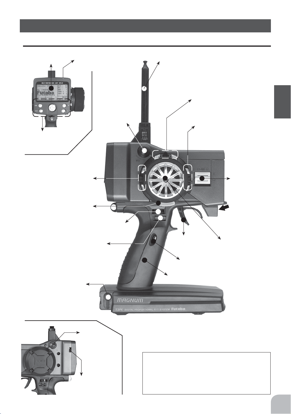
Nomenclature
Transmitter T3PKS
LCD screen
LED
Edit buttons
Digital Trim 2(DT2)
(default throttle trim)
See page 16 for operating instrucxtions.
Push switch 1 (SW1)
Digital Dial 1(DL1)
(default dual rate)
See page 16 for operating instrucxtions.
Digital Dial 2(DL2)
(default ATL)
See page 16 for operating instrucxtions.
Digital Dial 3
(DL3)
Antenna
Digital Trim1(DT1)
(default steering trim)
See page 16 for operating instrucxtions.
Digital Trim 3(DT3)
See page 16 for operating instructions.
Power
switch
Mechanical ATL
adjusting screw
See page 17
for ajastment instructions.
Throttle
trigger
Steering
wheel
Push switch 2 (SW2)
Before Using
Sound port
Use a commercial earphone
with 3.5mm diameter plug.
Push
switch 3
(SW3)
Display switch
Grip Handle
*The switches, dial, and trimmers in the figure are shown in the initial setting position.
Precautions when turning the power
switch on and off.
When the data was changed using the edit keys or trim levers,
wait at least two seconds before turning off the power. If the
power is turned off within two seconds after the data was
changed, the new data will not be written to memory.
15
Page 16
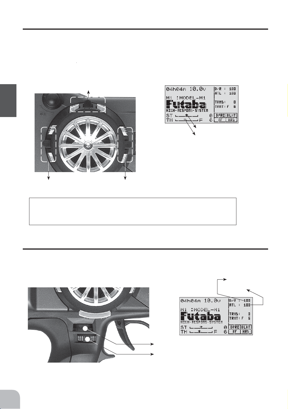
Digital Trim Operation
(Initial settings: DT1: Steering trim, DT2: Throttle trim, DT3: -------)
Digital trims can be used in 2 ways:
Operating by the lever: Push the lever to the left or right (up or down) Operating by push
button switch: Press the push button switch in the desired direction. The current position
is displayed on the LCD screen in the bottom three rows of the list.However, this operation cannot be performed when the trim/dial lock (p.22) function is set.
Before Using
DT2 DT3
Trim Operation
With the center trim feature, trim adjustments have no effect on the maximum servo travel. This prevents the linkages from binding when adjustments are made.
DT1
Steering trim display
Throttle trim display
• Each step is indicated by a tone.
• When the trim exceeds the maximum trim adjustment
range, the beepwill change and the servo will not move
any farther. Return to the neutral position (center) by
pressing both the push button switches simultaneously
for about one second.
• Trim lever adjustments have no effect on the maximum
servo travel.This prevents the linkages from binding
when adjustments are made.
16
Grip Dial Operation
(Initial setting: DL1; Steering D/R, DL2; ATL)
Operate the dials by turning them. The current set value is displayed on the LCD screen.
However, this operation cannot be performed when the trim/dial lock (p.22) function is set.
Steering D/R display
ATL displaydisplay
Steering D/R DL1
ATL DL2
• Each step is indicated by a tone.
• When the trim exceeds the maximum trim
adjustment range, the tone will change pitch
and the lever will not move any farther.
Page 17
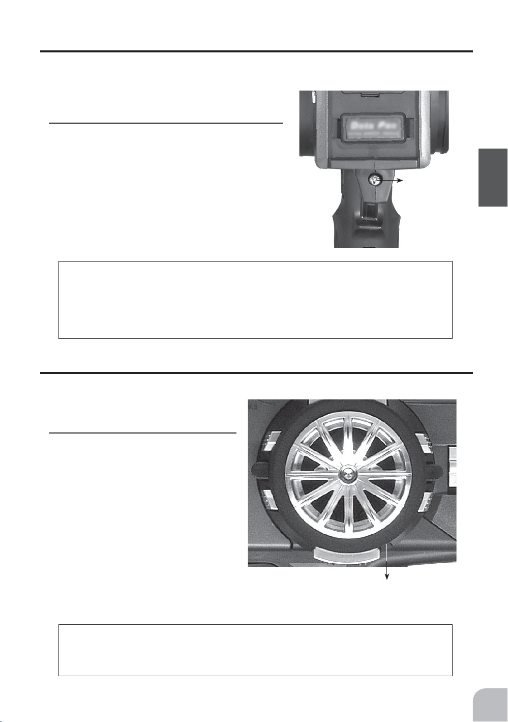
Mechanical ATL adjustment
Make this adjustment when you want to decrease the stroke of the brake (back) side of
the throttle trigger for operation feel.
Adjustment
1
Using a Phillips screwdriver adjust the trigger
brake (reverse) stroke. (The screw moves the
throttle trigger stopper.)
• When the screw is turned clockwise, the stroke becomes
narrower. Adjust the stroke while watching the screw.
Note:
Once you have changed the mechanical stroke on the brake side, be sure to adjust the scale of the throttle channel accordingly by using the "Adjuster Function"
(page102).
Due to this change, you also need to adjust in most cases the travel of the throttle
servo by using "Data Setting."
Mechanical
ATL adjusting
screw
Before Using
Wheel tension adjustment
Make this adjustment when you want to change the wheel spring tension.
Adjustment
1
Using a 1.5mm hex wrench adjust the
wheel spring tension by turning the
screw inside the adjusting hole in the
arrow direction.
• The spring is set to the weakest tension at
the factory.
• When the adjusting screw is turned clockwise, the spring tension increases.
Wheel tension adjusting screw
Note:
If turned too far counterclockwise, the adjusting screw may fall out. The adjustment range is up to 7 to 8 turns from the fully tightened (strongest) position. If
turned further than this, the adjusting screw may fall out.
17
Page 18
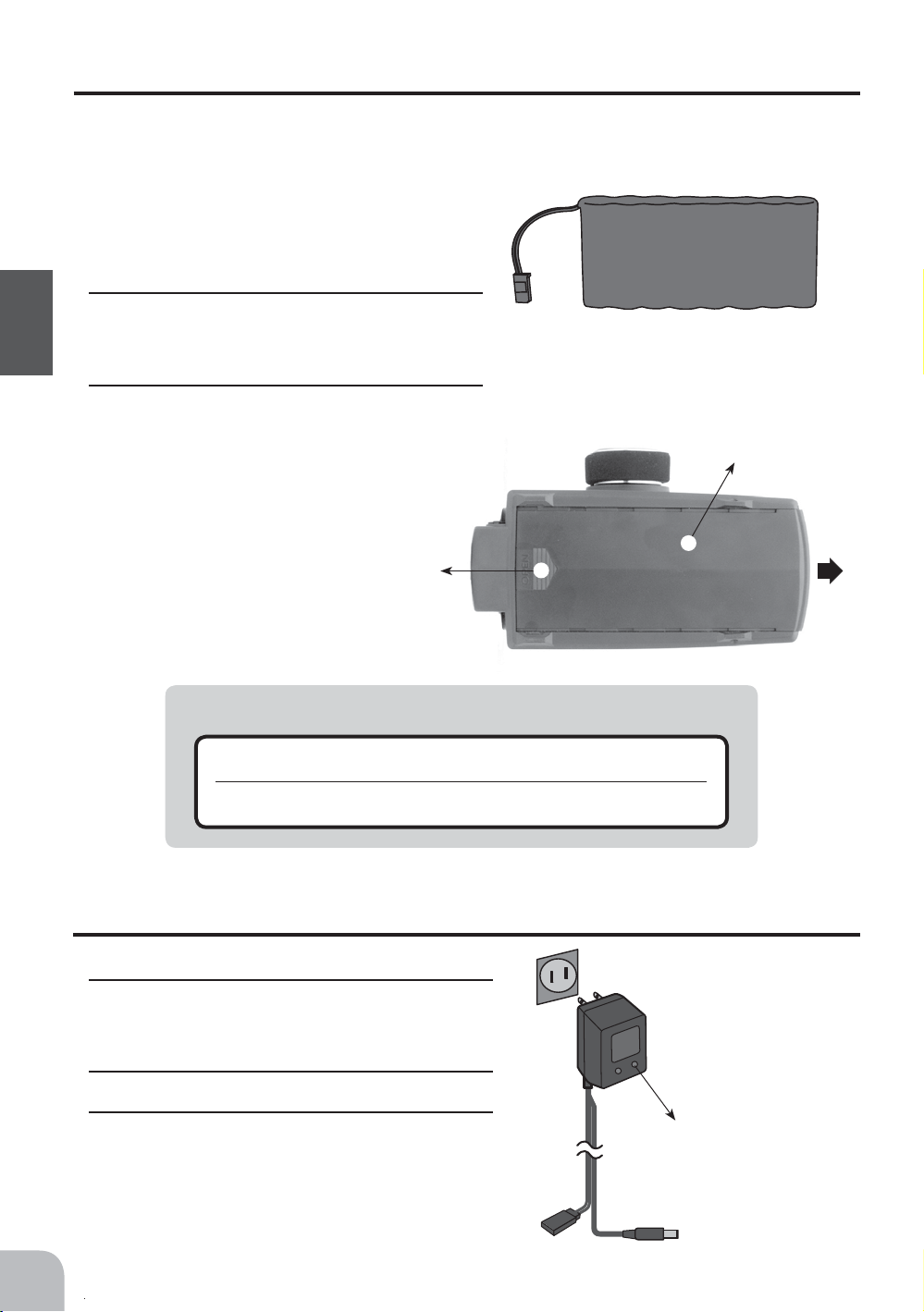
Ni-cad Battery Replacement
The Ni-cad battery is connected by a connector so that it can be removed when you will
not be using the transmitter for a long time, or when replacing a dead battery with a
spare battery.
• Always use an NT8F7000B Ni-cad battery.
Removal
1
Slide the transmitter battery cover in the ar-
row direction while pressing the part shown
Before Using
in the figure.
2
Remove the Ni-cad battery and disconnect
the connector.
While pressing here Battery cover
Ni-cd battery
NT8F700B
Battery cover
i
Caution
Pay full attention so that the battery cover wouldn't pinch the cable
e
of the Ni-cad battery.
Pinching the cable by the battery cover can lead to an electrical shortage, fire and
abnormal heat generation, which may cause burns and fire disaster.
Charging the Ni-cad Battery
Charging
1
Plug the transmitter cord of the special char-
ger into the charging jack on the rear of the
transmitter.
2
Plug the charger into an AC outlet.
3
Check that the charging LED lights.
AC outlet
Charger
Transmitter charging
LED
Cord to transmitter
charging jack
18
Page 19
Cover
When charging the NT8F700B Ni-cad battery with the special charger, allow about 15 hours for charging. If the transmitter has not been used for some time, cycle the battery by
charging and discharging it two or three times.
Charging
jack
Warning
i
Never plug it into an outlet other than indicated voltage.
g
Plugging the charger into the wrong outlet may result in an explosion, sparking, or fire.
Do not insert and remove the charger when you hands are wet.
g
It may cause an electric shock.
Always use the special charger or a quick charger for digital proportional R/C sets to charge a
e
digital proportional R/C set Ni-cad battery.
Overcharging a Ni-cad battery can result in burns, fire, injuries, or loss of sight due to overheating, breakage, or electrolyte leakage.
i
Caution
Over current protection
The transmitter charging circuit is equipped with an over current protection circuits (1.5A). If the battery is charged with
a quick charger for other than digital proportional R/C sets, it
may not be fully charged.
Before Using
Never try to recharge a dry cell battery.
g
The transmitter may be damaged or the battery electrolyte may leak or the battery may break.
When the charger is not in use, disconnect it from the AC outlet.
e
Do this to prevent accidents and to avoid overheating.
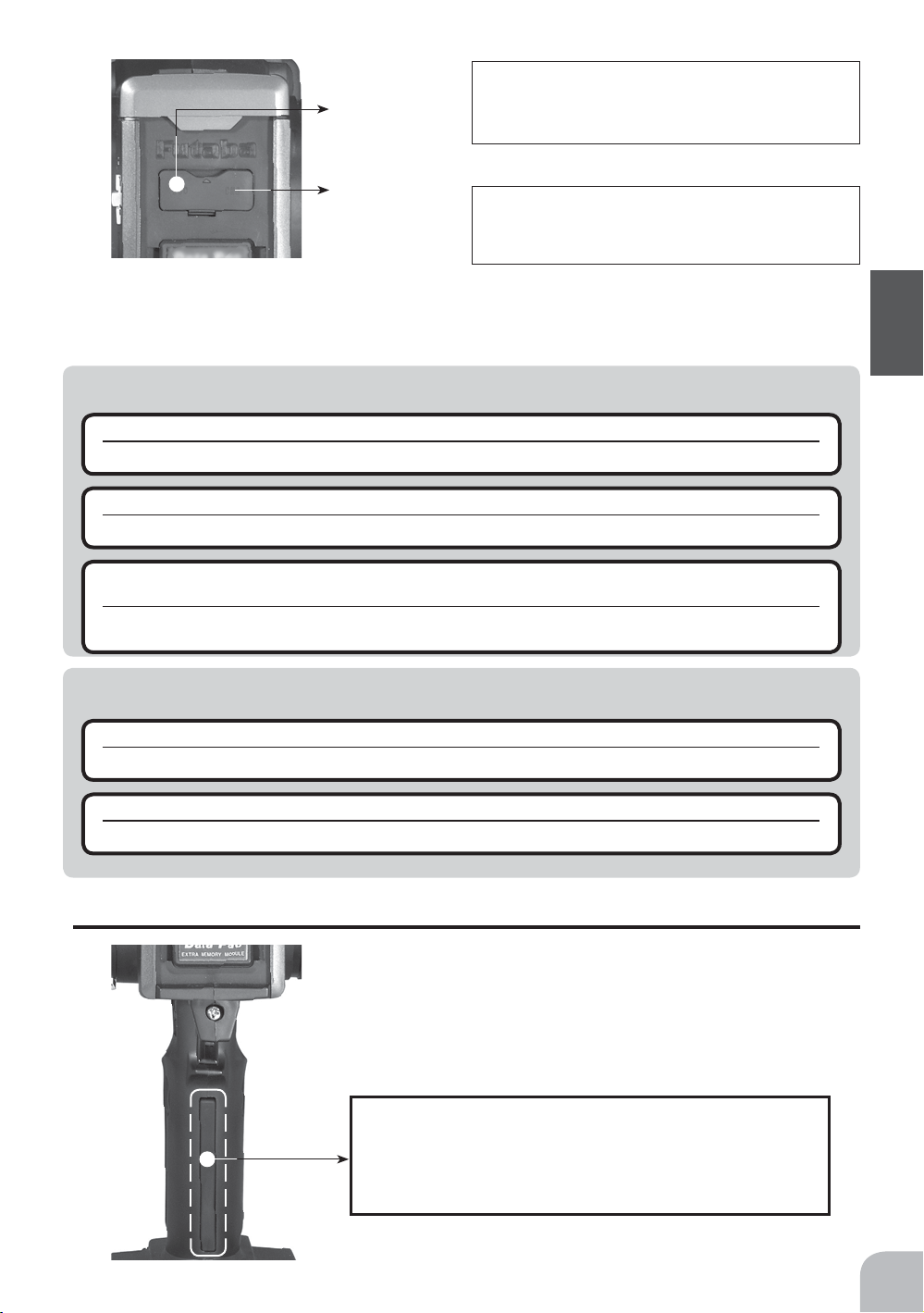
Grip vibrator
A vibrator is built into the grip of the T3PKS. The vibrator vibrates at racing timer lap navigation, time-up, and
low battery alarm. (p.104)
Note:
The vibrator motor is built into this part of the grip. If
too much force is applied to this part, the vibrator motor may operate. Note that the vibrator motor may be
damaged depending on situation.
19
Page 20
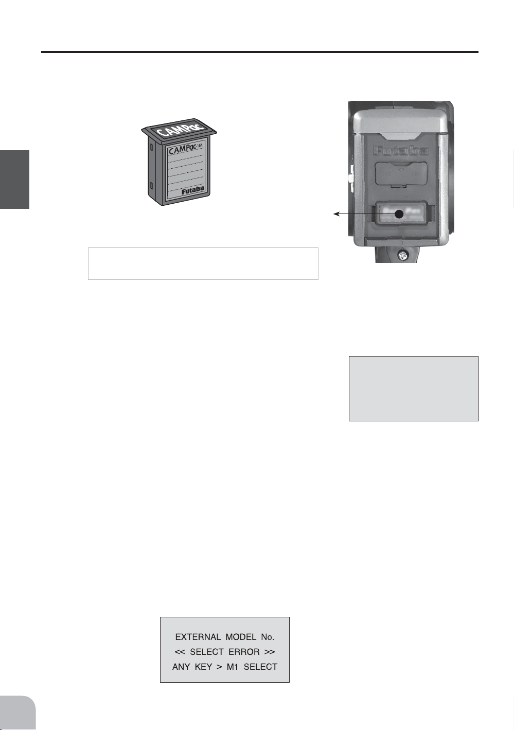
CAMPac-16K Memory module
The optional CAMPac-16K increases your model storage capability (to 30 modelsfrom
20) and allows you to transfer programs to another T3PKS transmitter. Note that data
may not be transferred to/fromany other model of transmitter (T3PK, T3VCS, etc).
CAMPac-16K
(Optional)
Before Using
CAMPac slot
Removal Precautions
Always turn off the transmitter power before
installing and removing the CAMPac-16K.
When inserting and removing the CAMPac-16K
Always turn off the transmitter power before removing or inserting the CAMPac-16K.
Initialization
When using the CAMPac-16K, initialization is necessary so
that the CAMPac-16K can be used with this transmitter. When
"INITIALIZE?" is displayed on the screen at power ON, press
the (+) button. This automatically initializes the CAMPac-16K.
MEMORY MODULE
INITIALIZE ?
YES > +
NO > -
No further action is necessary.
When a CAMPac-16K used with another model has been inserted, and initialization is
executed by pressing the (+) button when "INITIALIZE?" is displayed on the screen at
power ON, the old data is destroyed so the CAMPac-16K can be used with the T3PKS.
20
Model Select Error
If the power is turned back on in the state in which a model memory in the CAMPac16K was called and the CAMPac-16K is not installed, an audible alarm will sound and
"SELECT ERROR" will be displayed on the LCD screen. When any button is pressed,
model 1 will be forcibly called.
LCD screen:
Audible alarm:
Tone sounds (7 times)
and stops (repeated)
Page 21
Data interchangeability with other models
Data is not interchangeable with T3PK, T3VCS, and other transmitters other than the
T3PKS.
Set data backup
The set data of each function (transmitter body and the CAMPac-16K) of the T3PKS
transmitter is stored in a memory element that does not require a backup battery. Therefore, the T3PKS transmitter can be used without paying attention to the backup battery
life.
Display switch
If the display switch is turned on without turning on the power switch, transmitter side
data setup is possible without emitting radio waves.
Display switch
ON
OFF
"DISP" is displayd
Warning
i
Never turn on the power switch while this function is in use.
g
If the power switch is turned on, radio waves will be emitted and interfere with
same band (frequency) and is very dangerous.
vehicles (boats) operating on the
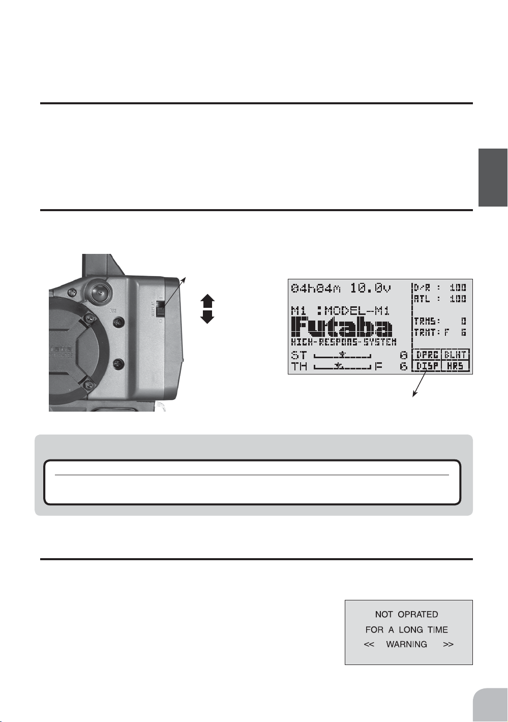
Power off forgotten alarm
When the steering wheel, throttle trigger, push switch, or edit button is not operated for
10 minutes during T3PKS initialization, an alarm sounds and "NOT OPRATED FOR
LONG TIME" is displayed on the LCD screen.
When the steering wheel, throttle trigger, push switch, or edit
button is operated, the alarm is reset. If the system is not to be
used, turn off the power.
The function can be deactivated at the system menu (p.98).
Before Using
21
Page 22
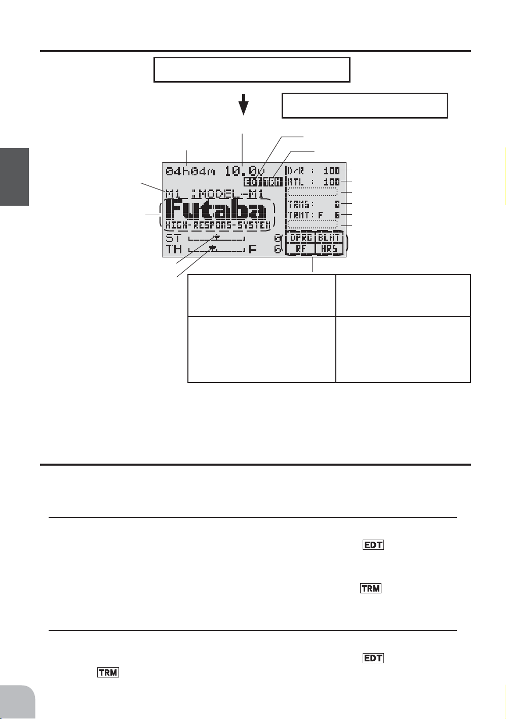
Display when power switch turned on
Power switch turned on
Beep confirmation sound is generated and the
initial screen shown below appears.
Model name (10 characters)
* Display mode can be
Before Using
changed by using the SYSTEM function. (See pge 98)
User name display
When the (END) button is held down for 1 second or longer at the initial screen, the
Futaba logo and user name are displayed for about 2 seconds.
Total timer display (H:M)
Steering trim display
Throttle trim display
Battery voltage display
Edit button lock display
Trim/dial lock display
Displays whether or not a memory
module is inserted. When a memory
module is inserted, "DPAC" is displayed.
When radio waves are being
emitted, "RF" is displayed. When
radio waves are not being emitted
when turned on by display switch
and when the DSC function is
used, "DISP" is displayed.
DL1
*Function names and rate
assigned to dials are dis-
DL2
played.
DL3
DT1
DT2
DT3
"BLHT" is displayed when backlighting is ON.
Displays whether or not a
memory module is inserted.
When a memory module is
inserted, "DPAC" is displayed.
22
Edit button lock and trim/dial lock
T3PKS setup and operation by edit button (p.15) and digital trim DT1, DT2, and DT3
and dials DL1, DL2, and DL3 can be prohibited.
Setting
1
Edit button lock; When the (+) button is pressed for about 1 second at the initial screen,
a confirmation beep is generated and the edit button lock display appears on the
screen.
Trim/dial lock; When the (-) button is pressed for about 1 second at the initial screen,
a confirmation beep is generated and the trim/dial lock display appears on the
screen.
Clearing
1
Edit button lock and trim/dial lock can be cleared in the initial screen state by the same
method as setting described above. (The edit button lock display or trim/dial lock
display disappears from the screen.)
Page 23
Total timer
The total timer shows the accumulated time from last reset.
The total time does not change even when the model changes.
Reset method
1
In the initial screen state, hold down the (+) and (-) buttons simultaneously for 1 second.
* The total timer display counts up from 1 minute to 99hours 59 minutes.
LCD Screen Contrast
The LCD screen contrast can be adjusted. (For more information, see page98.)
Caution
Do not adjust the contrast so that the LCD is too bright or too dark.
When the display cannot be read due to a temperature change, data cannot be set.
LCD Screen Temperature Change
In the following cases, the LCD may become difficult to read due to a temperature
change.
- On hot summer days and cold winter days, the LCD may be easy to read indoors, but difficult to read outdoors.
- If the contrast is too bright or too dark, temperature changes and lighting conditions may cause the screen to
become difficult to read.
Before Using
Contrast adjustment when no longer called
1
Turn on the transmitter.
2
If the screen is too dark, adjust the contrast by pressing the (-) button while
pressing the (JOG) button. If the screen is too light, adjust the contrast by pressing the (+) button while pressing the (JOG) button.
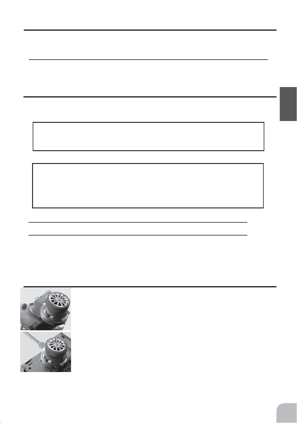
Changing wheel position and modifying for left-hand use
Changing the wheel position
The wheel position can be offset by using the accessory APA
wheel position offset adapter.
(See the next page for the modification method.)
Modifying for left-hand use
The wheel section left and right installation direction can be reversed.
(See the next page for the modification method.)
Angle can be adjusted
The angle can be fine adjusted by adjusting the steering wheel unit installation. (See the
modification method on the next page for the adjustment details.)
23
Page 24
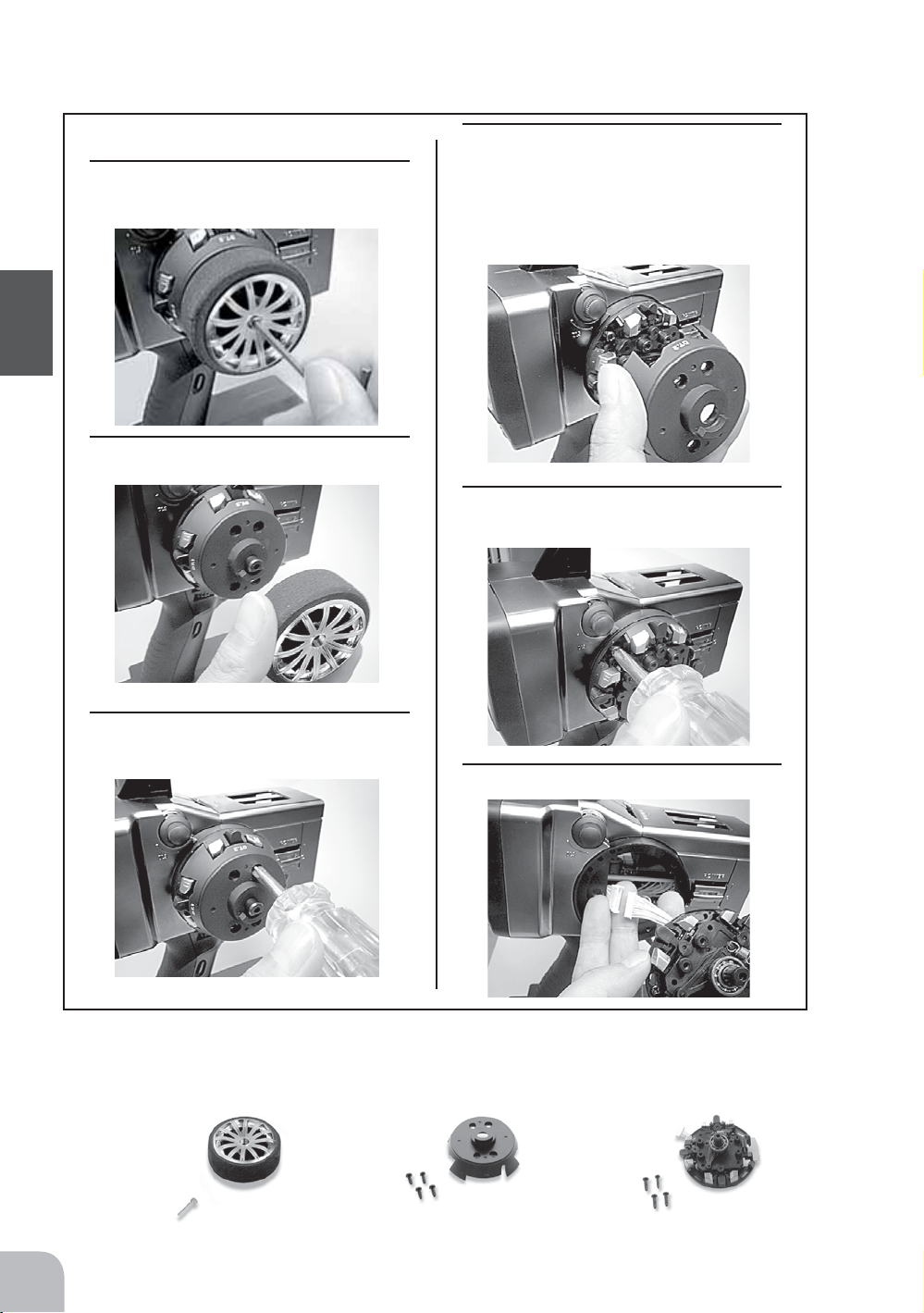
Removing the steering wheel unit
Before Using
• Obtain a 2.5mm hex wrench and philips
screwdriver.
1
Hold the wheel and remove the
screw.
2
Pull off the wheel.
4
Remove the steering wheel unit.
• While pushing the end of the steering wheel shaft (so that the shaft
will not come off together with the
cover), remove the cover.
5
Remove the 4 steering wheel screws.
3
Remove the 4 steering wheel unit
cover screws.
6
Disconnect the connector.
• During this work, handle the unit carefully so that the shaft and other parts mounted to the internal
steering wheel unit do not fall out.
• The length of the screws used at each part differs as shown in the photos below. When reassembling
the steering wheel unit, always use the original screws
Steering wheel mounting screw (1) Cover mounting screws (4) Unit mounting screws (4)
24
Page 25
Installing the accessory APA steering wheel offset adapter
• Obtain a 2.5mm hex wrench and philips screwdriver.
• Install the steering wheel unit removed as described on the preceding page as follows:
1
Connect the steering wheel unit con-
nector (be careful of the direction of
the connector) through the adapter,
and install the adapter using the 4 accessory hex bolts.
2
Install the steering wheel unit, steer-
ing wheel cover, and wheel to their
original positions.
Modifying for left-hand use
• Obtain a 2.5mm hex wrench and philips screwdriver.
• Install the steering wheel unit removed as described on the preceding page as follows:
1
Remove the wheel section rear
cover using the hex wrench.
3
At the opposite side, connect the
steering wheel unit connector and
Install the steering wheel unit,
steering wheel cover, and wheel to
their original positions.
Before Using
2
Push in the disconnected connector
so that it can be connected at the
opposite side.
• The photo below shows the connector at
the front. Push it to the opposite side.
25
Page 26
Handling the RF Module
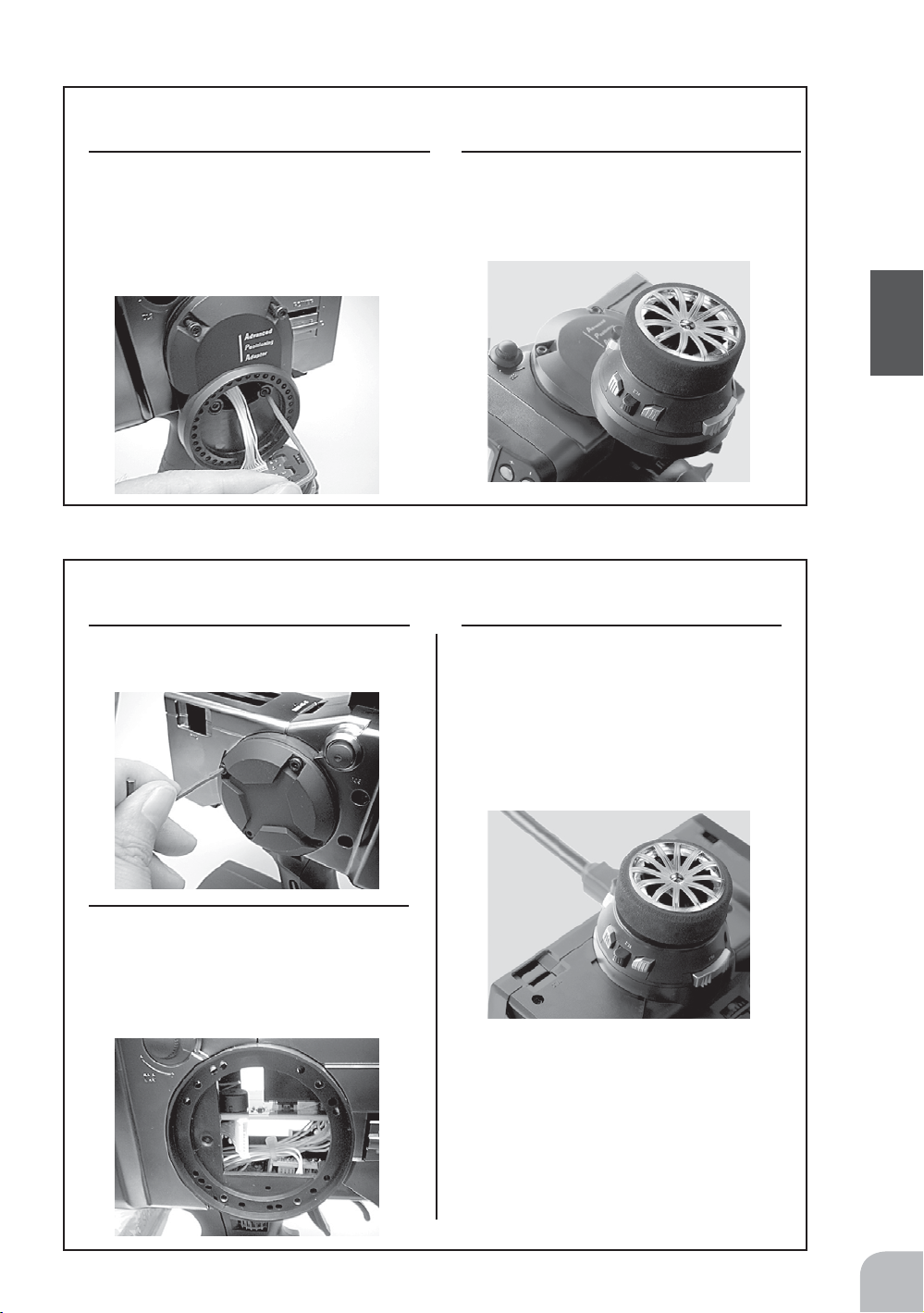
Removing the RF module
1
Remove the RF module cover by sliding it in the
arrow direction.
2
Remove the module by pulling it upward while
pushing the left and right tabs to the inside.
RF module cover
Before Using
Inserting the RF module
1
Insert the module while being careful that the
transmitter side connector pins are not bent.
2
Push in the module until the tabs engage with a
"click".
3
Slide on the RF module cover.
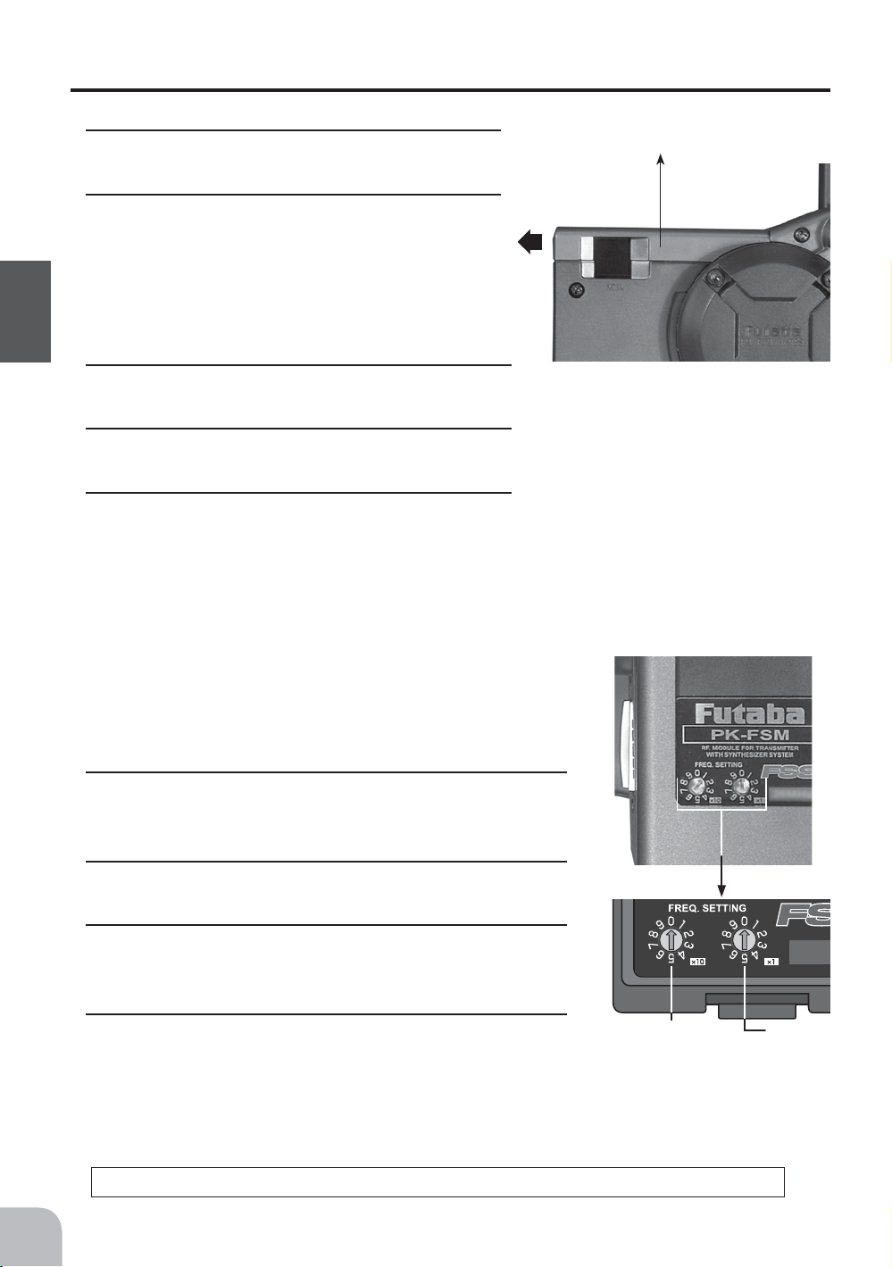
Synthesizer RF module PK-FSM
Perform the following frequency setting with the transmitter power switch in the OFF position.
Frequency band setting
1
Using the accessory mini screwdriver, set the digital
switch (x10 side) at the left side of the module to the tens
digit of the band No. you want to set.
26
2
Next, set the right side digital switch (x1 side) to the units
digit of the band No. you want to set.
3
Confirm that the receiver band matches the band above,
then set the power switches to ON in transmitter and receiver order.
4
Confirm that the system operates normally.
RF module temperature rise
"x10"
Channel No.
tens digit
During transmitter use, the temperature of the RF module may rise. This is normal.
"x1"
Channel No.
units digit
Page 27
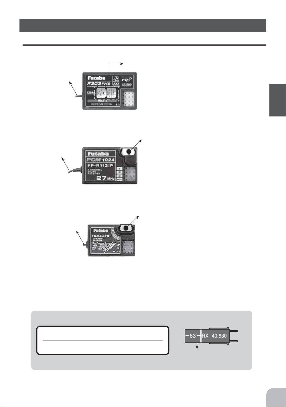
Nomenclature
Receiver
Frequency dials
Antenna
Antenna
Antenna
R303FHS
receiver
R113iP
receiver
R203HF
receiver
Connectors
1:Steering servo(CH1)
2:Throttle servo(CH2)
3:CH3 servo(CH3)
B/C:Power connector/DSC connector
Crystal
When changing the frequency, use the specified Futaba crystal set.
Connectors
1:Steering servo(CH1)
2:Throttle servo(CH2)
3:CH3 servo(CH3)
B/C:Power connector/DSC connector
Crystal
When changing the frequency, use the specified Futaba crystal set.
Connectors
1:Steering servo(CH1)
2:Throttle servo(CH2)
3:CH3 servo(CH3)
B/C:Power connector/DSC connector
Before Using
i
Caution
Do not peel off, or use the transmitter with a peeled
g
off, crystal frequency display tab seal.
It may cause a short circuit inside the set and the transmitter
may not transmit.
crystal frequency display tab seal
27
Page 28
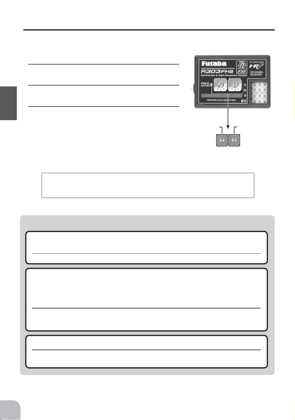
Synthesizer receiver R303FHS
Set the frequency band with the power switch in the OFF position.
Frequency band setting
1
Using the accessory mini screwdriver, set the left side
dial to the tens digit of the band No. you want to set.
2
Next, set the right side dial to the units digit of the
band No. you want to set.
3
Confirm that the transmitter band matches the band
Before Using
above, then set the power switches to ON in transmitter and receiver order.
R303FHS operation note
When the power is turned on, whether the receiver is in the HRS or PPM mode is judged and the R303FHs
operates in that mode until the power is turned off. When the transmitter mode was changed, operation becomes possible when the receiver power is turned on again. When the frequency band was changed, reception on the new frequency band becomes possible when the receiver power is turned on again.
Channel No.
tens digit
Channel No.
0
1
9
8
7
6
5
units digit
0
1
9
2
2
8
3
3
7
4
4
6
5
i
Caution
When using analog servos, always switch the T3PKS to the PPM mode.
e
Transmitter mode : PPM or PCM mode (See p.42 for setting method.)
The system will not operate normally in other modes. Such operation will cause servo trouble.
When using the T3PKs in the high response system (HRS) mode, always use it under the follow-
e
Receiver: R113iP(PCM), R303FHS(PPM)
ing conditions:
Receiver: R203HF, R303FHS or other high response system (HRS) compatible receiver
Servos : 6V Futaba digital servo
Battery : 6V NiCd battery
Transmitter mode : HRS mode (See p.42 for setting method.)
If the conditions are different, control is impossible.
And Fail Safe Unit (FSU) is not available.
Always use only genuine Futaba transmitters, receivers, servos, FET amps (electronic speed
e
controls),Nicad batteries and other optional accessories.
Futaba will not be responsible for problems caused by the use of other than Futaba genuine parts. Use the parts specified in the instruction manual and catalog.
For the receiver, servos, and other connections, see page 29. For the DSC cord (option)
connections, see page 112.
28
Page 29
Installation
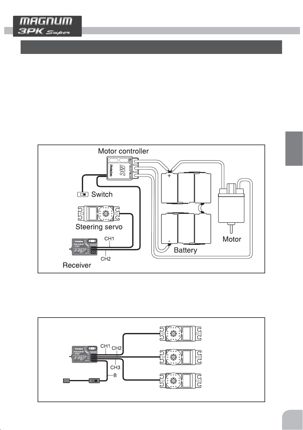
Receiver and Servo Connections
Connect the receiver and servos as shown below. Connect and install the receiver and
servos in accordance with "Installation Safety Precautions" on the next page.
The figure shown below is an example. The method of connecting the motor controller to
the motor and battery depends on the motor controller used. Purchase the motor controller and servos separately. The receiver also depends on the set.
Installation When An Motor controller Is Used
Receiver
To Battery
Installation
Installation For Gas Powered Models
Steering servo
Throttle servo
CH3 servo
Switch
29
Page 30
Installation Safety Precautions
Warning
i
Receiver (receiver antenna)
Do not cut or bundle the receiver antenna wire.
g
Do not bundle the receiver antenna wire together with the motor controller lead wire.
g
Keep the receiver antenna wire at least 1cm away from motor, battery, and other wiring carrying heavy current.
g
Do not use a metal receiver antenna holder on a plate made of metal, carbon, or other conductive material.
g
Install the receiver antenna holder as close as possible to the receiver.
e
If the antenna wire is cut, bundled, or routed near a noise source, the receiving sensitivity will drop, the running (sailing)
range will decrease, and you may lose control of the model.
*Noise is transmitted through metal, carbon, and other conductive material, so keep the receiver antenna wire away from such parts.
Installation
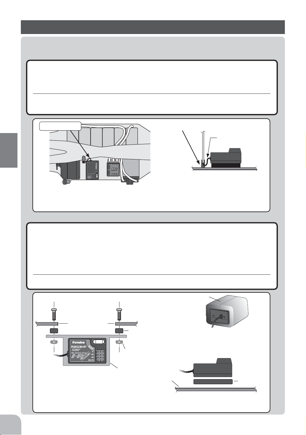
Antenna
Install the receiver as far away from battery, motor controller, motor, silicon cord and other noise sources. Keep
it away from the antenna wire, in particular.
Antenna holder
Antenna wire does
not touch the plate.
Install the antenna holder as close as possible to the
receiver. The surplus antenna wire from the receiver
to the antenna holder is affected by noise. Do not use
a metal antenna holder on a plate made of metal, carbon, or other conductive material.
Receiver vibration-proofing/waterproofing
(Car)
Vibration-proof the receiver by wrapping it in foam rubber or other vibration-absorbing material
e
and mount it with thick double-sided tape.
When using the receiver holder supplied with the model kit, mount the holder to the chassis
e
through a rubber grommet.
(Boat)
Vibration-proof the receiver by wrapping it in foam rubber or other vibration-absorbing material.
e
Also waterproof the receiver by sealing it in a plastic bag.
If the receiver is exposed to strong vibration and shock, it will operate erroneously due to the invasion of water drops
and you may lose control of the model.
Foam rubber, etc.
30
Mechanical plate
Nut (as required)
Receiver holder
When using the receiver holder supplied with the kit, install the receiver
through a rubber grommet.
Screw
Damper
Mechanical plate
When mounting the receiver with double-sided tape,
do not use a stiff tape. Stiff tape does not have a vibration-proofing affect.
Wrap the receiver in foam rubber or other
vibration-absorbing material. Do not use
hard material. Hard material does not
have a vibration-proofing affect.
Thick doublesided tape
Page 31

Warning
i
Connector Connections
Be sure the receiver, servo, crystal and connectors are fully and firmly connected.
e
If vibration from the model cause a connector to work loose while the model is in operation, you may lose control .
Servo Installation
When you install the servos always use the rubber grommets provided in servo hardware bags.
Mount the servos so they do not directly come in contact with the mount.
If the servo case comes in direct contact with the mount vibration will be directly transmitted to the servo.
If this condition continues for a long time the servo may be damaged and control will be lost.
Screw
Damper
Eyelet
Mechanical plate
Nut (as required)
When installing the servo, always install the accessory
rubber grommet and grommet flush against the servo.
(or)
A vibration-proofing affect is not obtained
even if the rubber grommet and grommet are
installed correctly whether or not the servo case
and mounting plate touch or do not touch.
Servo Throw
Operate each servo over its full stroke and be sure the linkage does not bind or is loose.
e
The continuous application of unreasonable force to a servo may cause damage and excessive battery drain.
s
e
t
a
ic
d
in
e
!
is
n
o
o
n
i
g
t
u
a
ow
C
h
A
that the steering servo is
Decide the EPA value at the
contact point.
Adjust the steering servo so that unreasonable force is not applied to the servo by the
chassis at maximum servo travel.
lin
im
.
t
e
s
ly
r
e
p
ro
p
Adjust the throttle servo so that unreasonable force is
not applied when the engine carburetor is full open, full
close, and the brakes are applied fully.
Especially, the braking effect becomes poor by heating
of the brakes while running. Before running, adjust the
suitable maximum servo travel so that unreasonable
force is not applied even when the servo travel is increased while running.
Installation
31
Page 32

Warning
i
Electronic speed control
Install the heat sinks where they will not come in contact with aluminum, carbon fiber or other
e
parts that conduct electricity.
If the FET Amp (Electronic speed control) heat sinks touch other materials that conduct electricity a short circuit could
occur. This could result in loss of control and damage to the system.
Motor Noise Suppression
Always install capacitors to suppress noise when electric motors are used.
e
If capacitors are not properly installed you could experience erratic operation and reduced range as well as loss of control.
Installation
1
"-" side"+" side
Schottky diode
23
Motors with no suppressor capacitors, or inadequate
suppression, may cause the MC800C Ver.2 to malfunction. Always solder the capacitors supplied to
your motor.
The schottky diode improves the efficiency of the
speed control / motor combination and provides
extra protection to the brake FETs. The white ring
must always face the positive side.
Other Noise Suppression Methods
Be sure there are no metal parts in your model which under vibration can come in contact with
e
other metal parts.
Metal to metal contacts under vibration will omit a high frequency noise that will effect the receivers performance. You
could experience erratic operation and reduced range as well as loss of control.
32
Page 33

Instal set-Up
Preparations (Transmitter)
Before setting the Transmitter functions, check and set items 1 to 4 below.
(Display when power switch turned on)
When the power switch is turned on, the currently selected model number is displayed.
Check of this number is model number you want to setup. To change the model number,
use the Model Select function (See page98).
Turn on the transmitter power.
(Start screen)
The model number is displayed.
1.RF Output Check
If signals are output normally, RF output monitor "RF" will
be displayed on the screen.
If "RF" is not displayed, check if the transmitter crystal and
RF module are installed.
If the transmitter is abnoemal or faulty, contact your Futaba
dealer.
Initial Set-Up
"RF"
When radio waves are not being emitted
when turned on by display switch and
when the DSC function is used, "DISP" is
displayed.
33
Page 34

2. Modulation Mode Check
The signal format of the electromagnetic waves output by
the T3PKS transmitter can be changed to match the type
of receiver used. Confirm that the transmitter can be set to
match the receiver used. When using an FM receiver (e.g.
R133F), the signal format must be set to "PPM", when using a
PCM receiver (e.g., R113iP), the signal format must be set to
"PCM", and when using an HRS receiver (e.g., R203HF), the
signal format must be set to "HRS". If the setting is incorrect, change the setting using
the HRS/PCM/PPM select function (page 42).
With the R303FHS, when the power is turned on, whether the mode is the HRS or PPM
mode is judged and the receiver is operated in that mode until the power is turned off.
When the transmitter mode was changed, operation becomes possible when the receiver
power is turned on again. See page 28 for the usage precautions related to the R303FHS.
3. Throttle Mode check
-When using the T3PKS transmitter with a boat, throttle
brake operation can be shut down by setting the BOAT function (page 72) *TRG-BRK item to "Cut-OFF".
-The throttle servo travel can be set to 50:50 or 70:30 for
throttle trigger operation as required by the throttle mode
Initial Set-Up
function (p.74).
"HRS"
4. Trims Initial Set-Up
- Steering trim (DT1) check
At initial set-up, steering trim is assigned to the DT1 trim
lever above the steering wheel. Operate the lever and make
sure the marker moves on the ST graph. If default has been
changed, test steering trim in its new location. After checking the trim, set the trim display to the center (N) position.
- Throttle trim (DT2) check
At initial set-up, throttle trim is assigned to the DT2 trim
lever left side the steering wheel. Operate the lever and make
sure the marker moves on the TH graph. If default has been
changed, test throttle trim in its new location. After checking
the trim, set the trim display to the center (N) position.
Throttle trim (DT2)
Steering trim
Throttle trim
Steering trim (DT1)
34
Page 35

- Steering dual rate (BT1) check
At initial set-up, steering dual rate (D/R) is assigned to DL1
dial, at the grip of the transmitter. Operate the DL1 and
check if the D/R value displayed on the screen changes. After
checking ST.D/R, set the steering dual rate to 100%.
- Throttle ATL (BT2) check
Steering dual rate
At initial setting, throttle ATL (ATL) is assigned to DL2 dial,
below DL1. Operate the DL2 and check if the ATL value
Throttle ATL
displayed on the screen changes. After checking TH.ATL, set
throttle ATL to 100%.
Steering dual rate dial DL1
Throttle ATL dial DL2
(Set-Up Procedure When Installed In a Car)
When installing the servos in a car, performing function set-up in the following order is
recommended.
Initial Set-Up
1
Perform step 4. Trims Initial Set-Up of Preparations on the preceding
page.
2
Set the servo direction of operation using the Reverse function. (See
page 43)
- The servo installation method and linkage direction depends on the kit. Therefore, the servo
operation direction may have to be reversed relative to transmitter operation. Before installing the servo, check the operating direction and set it using the Reverse function.
3
Set the subtrim and adjust the servo neutral point. (See page 44)
4
Set the trigger travel by adjusting the throttle trigger mechanical ATL to
you liking.(See page 17)
- When the stroke was adjusted, compensate the throttle by adjuster
function (See page102).
5
Set EPA of each channel and adjust the servo throw (travel). (See page 45)
35
Page 36

Function Map
s
s
s
s
s
Menu Selection
The function set-up screen can be easily selected from the function menu displayed on
the LCD screen.
The function menu can be selected from among the following 4 types to match the level
of use. To select the type, use the Menu type select function (See page 95).
-Level 1 (LEVEL1) : Basic functions only
-Level 2 (LEVEL2) : For middle class driver
-Big car(BIGCAR) : Displays the main functions for large cars (1/5).
-Level 3 (LEVEL3) : All functions can be selected. (For expert driver)
Edit Buttons
In this instruction manual, Edit Buttons are represented by the symbols shown below
Function Menu Screen
Call the menu screen by
button up, down, left,
Function Map
or right operation.
(Opening Screen)
Pres
Press the button to re-
turn to the Start Screen
LEVEL1
Pres
LEVEL2
Pres
BIGCAR
Pres
LEVEL3
36
Pres
Switch MENU1 and MENU2 by
pressing the
button.
Page 37

s
s
s
s
Menu Screen
The menu screen displays 18 items on 3 rows and 6 lines on one page and displays up to
36 items on 2 pages designated MENU1 and MENU2.
A menu screen matched to the purpose can also be created by using the menu customize
function described on page 38. The menu No. of the function indicated by the cursor is
displayed at the top right-hand
corner of the screen. When a
When the cursor is in a position without
a function assigned, OFF is displayed.
Menu No. of the function indicated
by the cursor is displayed.
function is not assigned, OFF is
displayed at the top right-hand
corner of the screen.
The screen above is an example
of the LEVEL2 MENU1 menu.
Calling the setup screen
Call the menu screen by
button up, down, left, or
right operation.
(Opening Screen)
Pres
press the button to re-
turn to the Start Screen
press the
turn to the Start Screen
button to re-
Example of menu LEVEL2
Switch MENU1 and MENU2 by
pressing the
Pres
Pres
button.
Pres
On the menu screen, select
the function by moving the
cursor by
down, left, or right operation.
The highlighted item is the currently selected function.
Call the setup screen by
pressing the
button up,
Function Map
button.
The screen on the right
shows an example of setting
EPA function.
(Function Set-up Screen)
37
Page 38

s
s
s
s
s
Custom Menu
A menu matched to the purpose (custom menu) can be created by using the menu customize function.
A different menu can be created for each model memory.
Menu assignment
1
Call the menu screen from the initial screen by (JOG) button
up, down, life, or right operation.
2
Use the (+) button to Select the MENU1 or MENU2 screen
too be edited.
3
Press the (-) button for about 1 second. A confirmation beep
is generated and the menu customize screen is displayed.
4
Select the location where the function is to be assigned or
modified by moving the cursor by (JOG) up, down, left, or
right operation.
5
Use the (+) or (-) button to select the function to be assigned.
6
When assignment is complete, end by returning to the menu
screen by pressing the (END) button.
(Opening Screen)
(MENU1 screen)
Pres
One point
This function allows modification of the menu list and
addition (except LEVEL3) or removal of functions. All
Function Map
the functions can also be grouped at MENU1 only de-
(MENU2 screen)
pending on the purpose.
(approx. 1sec)
Note:
This function consists of 3 fixed functions; *M-SEL (model select), *M-RES
(model reset), and * MENU-T (menu type select), and cannot be moved or deleted.
When the menu type is changed from the created customize menu to another
menu type by * MENU-T, the customize menu is reset and the menu is initialized to the original menu.
The set values of a function deleted from the menu remain valid. When an unused function is turned OFF or rate adjustment, etc. related to other functions is
performed, check the set values before deleting the function.
or
Pres
(CUSTOMIZE MENU screen)
Pres
38
Pres
Example of setting BAKE (brake mixing) where nothing
was set at LEVEL2 MENU1.
Pres
The highlighted item is the currently selected function.
Page 39

Direct Selection
The Direct Selection allows instant access to the six functions most frequently used.
The function set-up screen can be directly and quickly called with the special buttons
for each of the eight functions, they can be freely selected as the Direct Selection Button
function.
INITIAL SETTING
Direct
No
Button
Function ab-
breviation
Function
Chanel End
1.
Press
2.
3.
4.
7
Press
5.
6.
1
2.3.4.5.6
8
7.
8.
Press
Press
EPA
STSPD
STEXP
SUBTR
THEXP
THSPD
M-SEL
A.B.S
Point Adjuster
Steering Soeed
Steering EXP
Subtrim
Throttle EXP
Throttle Speed
Model Select
A.B.S
Call the direct Selection
screen by pressing the
button.
(Opening Screen)
press the button to re-
turn to the Start Screen
Upon your needs, select one of the
8 functions and then click its button
to call the Function Set-up Screen.
(Direct Selection Screen)
press the button to return
to the Direct Selection Screen
(Function Set-up Screen)
Press the but-
ton to return to
the Start Screen
The screen on the
left shows an example of
EXP
Throttle
function.
Function Map
39
Page 40

List of functions by menu type
Function Map
Function
No
1
2
3
4
5
6
7
8
9
10
11
12
13
14
15
16
17
18
19
20
21
22
23
24
25
26
27
28
29
30
31
32
33
34
35
36
Function abbreviation
EPA
STEXP
STSPD
THEXP
THSPD
A.B.S
ACCEL
START
BRAKE
IDLUP
TIMER
LAP-L
PMIX1
PMIX2
BOAT
SUBTR
REV
F/S
*
M-SEL
*
M-RES
M-COP
NAME
DIAL
SWTCH
D/R
ATL
CH3
P-MOD
*
MENU-T
SYSTM
DCALL
SERVO
MCSET
ADJST
VIBRA
THMOD
LEVEL1 LEVEL2 BIGCAR LEVEL3
(Initial setting)
40
Page 41

Function list
Function
No
1
2
3
4
5
6
7
8
9
10
11
12
13
14
15
16
17
18
19
20
21
22
23
24
25
26
27
28
29
30
31
32
33
34
35
36
Function
abbreviation
EPA
STEXP
STSPD
THEXP
THSPD
A.B.S
ACCEL
START
BRAKE
IDLUP
TIMER
LAP-L
PMIX1
PMIX2
BOAT
SUBTR
REV
F/S
*
M-SEL
*
M-RES
M-COP
NAME
DIAL
SWTCH
D/R
ATL
CH3
P-MOD
*
MENU-T
SYSTM
DCALL
SERVO
MCSET
ADJST
VIBRA
THMOD
Description of function
End point adjustment
Steering curve adjustment
Steering servo delay
Throttle curve adjustment
Throttle servo delay
Pumping brake
Function which adjusts the rise characteristic from the throttle neutral position
Throttle preset at start function/ engine cut off by switch
Front and rear independent brake control for 1/5GP car, etc.
Idle up at engine start
Up, down, lap, or lap navigation timer
Lap timer data (lap time, average lap time) check
Programmable mixing between arbitrary channels
Programmable mixing between arbitrary channels
Boat, etc. brake operation stop/outboard engine tilt mixing
Servo center position fine adjustment during linkage
Servo operation reversing
HRS, PCM mode fail safe, battery fail safe
Model memory call
Model memory reset
Model memory copy
Model memory name set/modify, username set/modify
Selection of functions operated by digital dial and digital trim
Selection of functions operated by push switches
Steering angle adjustment while running (dual rate and second dual rate)
Brake side adjustment
Channel 3 servo operation position set/check
Modulation (HRS/PCM/PPM) select (transmit signal mode modification)
Function menu type selection
Backlighting/LCD contract/buzzer sound/LED display color/initial screen display
mode/power off forgotten function adjustment or setting
Function assignment to direct function select button
Displays servo operation on a bar graph
MC dedicated set-up of some commercial parts in HRS mode
Steering wheel and throttle trigger correction
Vibrator setting
Throttle servo forward and brake operation proportion setting
Page
No
P-45
P-52
P-57
P-53
P-59
P-65
P-48
P-62
P-70
P-75
P-82
P-89
P-76
P-76
P-72
P-44
P-43
P-50
P-90
P-94
P-93
P-92
P-80
P-79
P-105
P-106
P-107
P-42
P-95
P-98
P-96
P-108
P-100
P-102
P-104
P-74
Function Map
41
Page 42

Function
Modulation ( HRS.PCM.PPM ) Select "P-MOD"
The signal mode output from the transmitter can be changed. (PPM/PCM/HRS)
Receiver
When using an FM receiver set to the PPM side, when using a PCM receiver, set to the
PCM side and when using an HRS receiver, set to the HRS side.
- When the mode was changed and when a model of a different mode was
selected, signals are output in the mode set at the point at which the
transmitter power was turned back on.
Calling the setup screen
*Calling from menu screen
(Opening Screen)
Menu screen call
by
button
MENU 1
MENU 2
MENU1/2 selection
button
by
Select the function
by button
At mode selection, the box cur-
sor moves.
he button
Press t
* When the direct call button is set,
the setup screen is also called by the
following method:
(Opening Screen)
DIRECT SEL
Press the button set
at this function.
Press t
he button
HRS/PCM/PPM mode selection
1
Function
(Mode selection)
Select the mode to be set by (JOG) button left or right operation. Selected by moving the box cursor.
2
(Writing to memory)
Press the (+) and (-) buttons simultaneously for 1 second.
- The "MEMORY" display is switched.
3
When ending setting, return to the initial screen by pressing
the (END) button twice (for direct selection, press the (END)
button once).
Mode currently set in memory.
Mode currently operating.
Mode selection
- Select by (JOG) button left or
right operation.
Mode
PPM, PCM, HRS
42
The signal is output in the new mode when the transmitter power is turned on again.
Modulation ( HRS.PCM.PPM ) Select "P-MOD"
Page 43

Servo Reverse "REV"
(All channel)
This function reverses the direction of operation of the servos related to transmitter
steering, throttle, and channel 3 operation.
However, when the position set by trim or subtrim shifts from
the center, the center becomes the opposite side.
Calling the setup screen
*Calling from menu screen
(Opening Screen)
Menu screen call
by
button
MENU 1
MENU 2
* When the direct call button is set,
the setup screen is also called by the
following method:
(Opening Screen)
DIRECT SEL
MENU1/2 selection
by
Select the function
by button
he button
Press t
Press t
button
he button
•Select the setting item by
button
*Blinks at the current setup
blinks at the current
*
channel.
setup item.
Channel
ST :Steering
TH :Throttle
CH3 :Channel3
Normal side
Revers side
Press the button set
at this function.
Sevo Reverse Function Setting
(Preparation)
Select the channel to be set by (JOG) button left or right op
eration. ST, TH, and CH3 on the screen blink.
1
(Servo reverse setting)
Use the (+) or (-) button to reverse the servo operation direction.
(Each channel can be set similarly.)
2
When ending setting, return to the initial screen by pressing
the (END) button twice (for direct selection, press the (END)
button once).
Servo Reverse "REV"
Channel selection
- Select by (JOG) button left or
-
right operation.
Select button
- Select with the (+) or (-) buttons.
Function
43
Page 44

Subtrim "SUBTR"
(All channel)
Use this function to adjust the neutral position of the steering, throttle and channel 3 servos.
*Subtrim adjusts the entire range of
the servo in the set direction.
Use to adjust the neutral position
Calling the setup screen
*Calling from menu screen
(Opening Screen)
Menu screen call
by button
MENU 1
MENU 2
* When the direct call button is set,
the setup screen is also called by the
following method:
(Opening Screen)
DIRECT SEL
MENU1/2 selection
by
Select the function
by button
he button
Press t
Press t
button
he button
•Select the setting item by
button
blinks at the current
*
setup item.
Channel
ST :Steering
TH :Throttle
CH3 :Channel3
Set the steering and throttle
digital trims to the neutral "0" position. Set CH3 to the center "0"
position.
90deg
44
Function
Press the button set
at this function.
Brake side operation stop method
(Preparation)
- Set the steering and throttle digital trims to the neutral "0" position. Set CH3 to the center "0" position.
- Select the channel to be set by (JOG) button up or down operation.
1
(Subtrim adjustment)
Use the (+) or (-) button to adjust the center.
(Each channel can be set similarly.)
2
When ending setting, return to the initial screen by pressing
the (END) button twice (for direct selection, press the (END)
button once).
Subtrim "SUBTR"
Channel selection
- Select by (JOG) button up or
down operation.
Adjust button
- Adjust with the (+) and (-) buttons.
- Return to the initial value "0" by
pressing the (+) and (-) buttons
simultaneously for about 1 second.
Subtrim
ST :L100~R100
TH :B100~F100
CH3 :-100~+100
Initial value : 0
Page 45

End Point Adjuster "EPA"
(All channel)
Use this when performing left and right steering angle adjustments, throttle high side/
brake side operation amount adjustment, and channel 3 servo up side/down side operation amount adjustment during linkage.
- Correct the maximum steering angle and left and right steering angles when there is a
difference in the turning radius due to the characteristics, etc. of the vehicle.
Maximum steering angle
The EPA function basically determines the maximum steering angle of each channel.
The functions shown below may have been adjusted or the operating range set by EPA
function may be exceeded. Check the linkage each time the following functions are adjusted.
- Sub trim (all channels)
- Program mixing slave side (all channels)
- Tilt mixing (steering, channel 3)
- Idle up (throttle)
- Start Function, Engine Cut (throttle)
- Throttle acceration (throttle)
ATL trim
ATL trim allows adjustment of the brake side operation amount during operation.
Therefore, when the operating angle is adjusted with throttle EPA, ATL trim must also
be taken into account.
Remark
When the steering angle is insufficient even though EPA is increased to maximum
(120%), the steering angle can be increased somewhat by using program mixing.
(Setup example: See page 76.)
Warning
i
Operate each servo over its full stroke and be sure
e
the linkage does not bind or is loose.
The continuous application of unreasonable force to a servo may
cause damage and excessive battery drain.
Adjust the steering servo so that unreasonable force is not applied to the servo by the
chassis at maximum servo travel.
!
n
o
i
t
u
a
C
A howling noise indicates
that the steering servo is
improperly set.
Decide the EPA value
at the contact point.
Function
Adjust the throttle servo so that unreasonable force is not applied when the engine carburetor is full open, full close, and
the brakes are applied fully.
Especially, the braking effect becomes poor by heating of the brakes while running. Before running, adjust the suitable
maximum servo travel so that unreasonable force is not applied even when the servo travel is increased while running.
End Point Adjuster "EPA"
45
Page 46

Calling the setup screen
*Calling from menu screen
(Opening Screen)
Menu screen call
by button
MENU 1
MENU 2
* When the direct call button is set,
the setup screen is also called by the
following method:
(Opening Screen)
DIRECT SEL
MENU1/2 selection
button
by
Select the function
by button
he button
Press t
he button
Press t
Press the button set
at this function.
•Select the setting item by
button
blinks at the current
*
setup item.
Setting item (channel and direction)
ST-LFT :Steering (left side)
ST-RGT :Steering (right side)
TH-FWD :Throttle (foward side)
TH-BRK :Throttle (brake side)
3C-UP :3rd channel (up side)
3C-DWN :3rd channel (down side)
Setting item (channel and
direction) selection
- Select by (JOG) button left or right
operation.
- The direction (ST-LFT and ST-RGT)
linked with the steering wheel is
switched.
- The direction (TH-FWD and THBRK) linked with the throttle trigger
is switched.
Function
Steering (EPA) adjustment
(Preparation)
- Before setup the steering wheel steering angle, set the steering D/R dial (initial setup: DL1) to the maximum steering angle
position 100%.
- Select the setting item "ST-LFT" by (JOG) button up or down
operation and make the following adjustments:
1
Steering (left side) adjustment
Turn the steering wheel fully to the left and
use the (+) or (-) buttons to adjust the steering
angle.
2
Steering (right side) adjustment
Turn the steering wheel fully to the right and
use the (+) or (-) buttons to adjust the steering
angle.
3
When adjusting the steering angle of another channel imme-
diately after this, see the adjustment method for that channel.
When ending setting, return to the initial screen by pressing
the (END) button twice (for direct selection, press the (END)
button once).
100%
Adjust button
Adjust with the (+) and (-) buttons.
- Return to the initial value "100"
by pressing the (+) and (-) buttons simultaneously for about 1
second.
Steering EPA
ST-LFT :0~120
ST-RGT :0~120
Initial value :100
46
End Point Adjuster "EPA"
Page 47

Throttle (EPA) adjustment
(Preparation)
- Before setting the throttle steering angle, set the throttle ATL
dial (initial setup: BT2) to the maximum steering angle position
100%.
- Select the setting item "TH-FWD" by (JOG) button up or
down operation and make the following adjustments:
1
Throttle (forward side) adjustment
Turn the throttle trigger fully to the high side and
use the (+) or (-) buttons to adjust the throttle angle.
However, when using an FET amp, set to 100%.
2
Throttle (brake side/reverse side) adjustment
Turn the throttle trigger fully to the brake side and
use the (+) or (-) buttons to adjust the throttle angle.
However, when using an ECS, set to 100%.
3
When adjusting the throttle angle of another channel imme-
diately after this, see the adjustment method for that channel.
When ending setting, return to the initial screen by pressing
the (END) button twice (for direct selection, press the (END)
button once).
100%
Adjust button
- Use the (+) and (-) buttons to
make adjustments.
- Return to the initial value "100"
by pressing the (+) and (-) buttons simultaneously for about 1
second.
Throttle EPA
TH-FWD :0~120
TH-BRK :0~120
Initial value : 100
When "CUT OFF", which prohibits trigger brake side operation in the boat mode (p.72),
"
was set, throttle
3rd channel servo (EPA) adjustment
(Preparation)
- Select the setting item "3C-UP" by (JOG) button up or down
operation and make the following adjustments:
1
3rd channel servo (up side) adjustment
Set the 3rd channel dial fully to the up side (+ side) and use
the (+) or (-) buttons to adjust the steering angle.
2
3rd channel servo (down side) adjustment
Select the setting item "3C-DWN" by (JOG) button up or
down operation and set the 3rd channel dial fully to the down
side (-) and use the (+) or (-) buttons to adjust the steering
angle.
3
When adjusting the steering angle of another channel imme-
diately after this, see the adjustment method for that channel.
When ending setting, return to the initial screen by pressing
the (END) button twice (for direct selection, press the (END)
button once).
TH-BRK" (brake side) cannot be adjusted.
Direction selection
- Select by (JOG) button up or
down operation.
Adjust button
Adjust with the (+) and (-) buttons.
- Return to the initial value "100"
by pressing the (+) and (-) buttons simultaneously for about 1
second.
Steering EPA
3C-UP :0~120
3C-DWN :0~120
Initial value :100
Function
End Point Adjuster "EPA"
47
Page 48

Throttle Acceleration "ACCEL"
The servo will jump to the input position at its maximum possible speed. Unlike exponential, which adjusts the whole throttle movement into a curve, throttle acceleration
simply "jumps" away from neutral and then leaves the remaining response linear.
Operation
- Operation near the throttle trigger neutral position
becomes a sharp rise.
- The forward and brake
sides can be set separately.
- When the brake mixing
function (p.70) is set, the
CH3 brake can also be set.
Set value
The standard value (100% point) of this setup effects the operation amount set by throttle EPA function.
Convenient usage method
For gasoline engine cars, the linkage must have a
clearance because one servo controls the engine carburetor and brake. Thus, there is a noticeable time
delay at both the forward and brake sides. Sharp
response comparable to that of electric motor cars is
obtained by reducing this clearance at the transmitter side.
Calling the setup screen
*Calling from menu screen
(Opening Screen)
Function
MENU 1
MENU 2
Press t
* When the direct call button is set,
the setup screen is also called by the
following method:
(Opening Screen)
DIRECT SEL
Menu screen call
by button
MENU1/2 selection
button
by
Select the function
by button
he button
he button
Press t
Press the button set
at this function.
100%
50%
0%
FWRD
•Select the setting item by
button
*
blinks at the current
setup item.
Servo travel
Clearance
(Throttle system)
100%
50%
0%
BRAK
Caburetor
Servo horn
Brake side
Setup item
FWRD :
Forward side
acceleration amount
BRAK :
Brake side
acceleration amount
Setting item
- Select by (JOG) button up
or down operation.
selection
48
Throttle Acceleration "ACCEL"
Page 49

Throttle acceleration adjustment
(Preparation)
- Select the setting item "FWRD" by (JOG) button up or down
operation and make the following adjustments:
1
(Forward acceleration amount adjustment)
Use the (+) and (-) buttons to adjust the acceleration amount.
"0" :No acceleration
"100" :Maximum acceleration (Approximately 1/2 of the forward side
steering angle)
2
(Brake side acceleration amount adjustment)
Select the setting item "BRAK" by (JOG) button up or down
operation and use the (+) and (-) buttons to adjust the acceleration amount.
"0" :No acceleration
"100" :Maximum acceleration (Brake side maximum steering angle)
3
(3rd channel brake side acceleration amount adjustment)
If the Brake Mixing is being set, the 3rd channel brake side
acceleration will become adjustable.
Adjust button
Adjust with the (+) and (-) buttons.
- Return to the initial value "0" by
pressing the (+) and (-) buttons
simultaneously for about 1 second.
Forward acceleration amount
(FWRD)
0~100
Initial value: 0
Brake side acceleration amount
(BRAK)
0~100
Initial value: 0
3rd channel Brake
Select the setting item"BRAK (3CH)" by (JOG) button up or
down operation and adjust acceleration amount by (+) or (-)
button.
"0" :No acceleration
"100" :Maximum acceleration (Brake side maximum steering angle)
4
When ending setting, return to the initial screen by pressing
3rd channel
acceleration
(BRAK 3CH)
0~100
Initial value: 0
brake side
the (END) button twice (for direct selection, press the (END)
button once).
Caution
When "TRG-BRK" is set to "CUT OFF" by boat mode function (p.72), the brake side
function is not activated.
Dial / Trim Setting
The throttle acceleration adujustment amount (FOWRD) , (BRAKE) and 3rd channel
(BRAKE) can be controlled with digital dial DL1, DL2, DL3 or digital trim DT3 etc.
with the function select dial function. (See page 80)
amount
Function
Throttle Acceleration "ACCEL"
49
Page 50

Fail Safe/Battery Fail Safe Function "F/S"
(All channel)
(This function can only be used with HRS or PCM1024 system receivers.)
Fail safe function
This function moves the steering, throttle and channel 3 servos to a preset position when
the receiver cannot receive the signal from the transmitter for some reason.
When the servo operation position is not set, this function operates so that the servos
remains in the position they were in immediately before reception was lost. When the
signal from the transmitter can be received again, this function automatically resets..
- For gasoline engine cars, it is recommended that the throttle channel be set to the direction that applies
the brakes.
- When the transmitter power is turned on, the transmitter transfers the fail safe data to the receiver and
continues to transfer the data every minute thereafter. Note that data for about 1 minute after the receiver
power is turned on is not transferred because usually, the transmitter power is turned on first and the receiver power is turned on next.
Battery fail safe function
When the receiver battery voltage drops to a certain voltage or less, this function moves
the throttle servo to the position set by fail safe function. When the voltage recovers, this
function automatically resets.
Battery fail safe function ON/OFF switching (PCM only)
Battery fail save function ON/OFF can be set at the transmitter.
For HRS system, this function cannot be turned off.
When electric motor car power, especially the receiver power, is supplied from a common power supply which is supplied from MC, we recommend that this function be
turned off because the receiver voltage may drop momentarily and the battery fail safe
function may be activated. (For HRS system, the fail safe function is turned off.)
50
Calling the setup screen
*Calling from menu screen
(Opening Screen)
Function
MENU 1
MENU 2
Press t
* When the direct call button is set,
the setup screen is also called by the
following method:
(Opening Screen)
DIRECT SEL
Menu screen call
by
MENU1/2 selection
button
by
Select the function
by button
he button
he button
Press t
Press the button set
at this function.
button
The screen which is displayed depends on
the mode (HRS, PCM). The screen shown
below is the PCM mode display screen.
•Select the setting item by
button
blinks at the current
*
setup item.
Fail Safe/Battery Fail Safe Function "F/S"
Setup item
ST :Steering
TH :Throttle
CH3 :Channel3
MODE :Battery fail safe function
ON/OFF
Displays the servo position when
fail safe is set.
The battery fail safe setting is
displayed in the PCM mode only.
Page 51

Fail safe function setup
(Preparation)
- Select the channel to be set by (JOG) button up or down operation.
1
(Servo position setup)
When the fail safe function operates, the steering wheel,
the throttle trigger or 3rd channel dial remains in the desired
operation position. When the (+) and (-) buttons are pressed
simultaneously for about 1 second, the servo position is displayed and you can confirm that the function was set.
When you want to release the setting, press the (+) or (-)
button for 1 second. "HOLD" is displayed.
(Each channel can be set similarly.)
2
When ending setting, return to the initial screen by pressing
the (END) button twice (for direct selection, press the (END)
button once).
Battery fail safe function ON/OFF (PCM only)
(Preparation)
- Select the setting item "MODE" by (JOG) button up or down
operation.
Setup item selection
- Select by (JOG) button up or
down operation.
Channel
ST :Steering
TH :Throttle
CH3 :Channel3
F/S position setup button
- The (+) and (-) buttons are
pressed simultaneously for
about 1 second.
HOLD setup button
- press the (+) or (-) button for 1
second.
1
(Battery fail safe function ON/OFF)
The function can be switched by pressing the (+) or (-) button.
2
When ending setting, return to the initial screen by pressing
the (END) button twice (for direct selection, press the (END)
button once).
The HRS mode F/S screen "HOLD" display shows that the
fail safe setting is OFF. The position immediately before
reception becomes impossible like PCM mode “HOLD” is
not held. The battery fail safe setting is not displayed. When
throttle fail safe is set, the battery fail safe function is also
activated and cannot be turned off.
(HRS mode F/S screen)
PPM mode F/S screen
The fail safe function cannot be used in the PPM mode. When
the F/S screen is called, ("NO RELATION"), which shows that
this function cannot be used, is displayed.
Function ON/OFF
OFF, ON
Initial value: OFF
Function
(PPM mode F/S screen)
Fail Safe/Battery Fail Safe Function "F/S"
51
Page 52

Steering EXP "STEXP"
(Steering system)
This function is used to change the sensitivity of the steering servo around the neutral
position. It has no effect on the maximum servo travel.
Racers Tip
When the setting is not determined, or the characteristics of the model are unknown,
start with 0%. (When EXP is set to 0%, servo movement is linear.)
Calling the setup screen
*Calling from menu screen
(Opening Screen)
Menu screen call
by button
MENU 1
MENU 2
* When the direct call button is set,
the setup screen is also called by the
following method:
(Opening Screen)
DIRECT SEL
MENU1/2 selection
by
Select the function
by button
he button
Press t
Press t
button
he button
Setup item
RATE: Steering EXP rate
Vertical cursor moves in step
with steering wheel operation.
Function
Press the button set
at this function.
Quick Mild
Dial / Trim Setting
The steering EXP adujustment (RATE)
can be controlled with with digital dial
DL1, DL2, DL3 or digital trim DT3
etc. with the function select dial func-
Wheel operation
tion. (See page 80)
Steering EXP adjustment
1
When you want to quicken steering operation, use the (+)
button to adjust the + side. When you want to make steering
operation milder, use the (-) button to adjust the - side.
2
When ending setting, return to the initial screen by pressing
the (END) button twice (for direct selection, press the (END)
button once).
Servo travel
-1% ~ -100%
+1% ~ +100%
Wheel operation
Adjustment range
-100~0~+100%
Adjust button
Adjust with the (+) and (-) but-
tons.
- Return to the initial value "0" by
pressing the (+) and (-) buttons
simultaneously for about 1 second.
52
Steering EXP "STEXP"
Page 53

Throttle EXP "THEXP"
(Throttle system)
This function makes the throttle high side and brake side direction servo operation
quicker or milder. It has no effect on the servo maximum operation amount.
For the high side, selection from among three kinds of curves (EXP/VTR/CRV) is also
possible.
Advice
When the course conditions are good and there is no sense of torque at the power unit,
set each curve to the + side (quick side). When the road surface is slippery and the
drive wheels do not grip it, set each curve to the - minus (mild) side.
Calling the setup screen
*Calling from menu screen
(Opening Screen)
Menu screen call
by button
MENU 1
MENU 2
* When the direct call button is set,
the setup screen is also called by the
following method:
(Opening Screen)
DIRECT SEL
MENU1/2 selection
by
Select the function
by button
he button
Press t
Press t
button
he button
•Select the setting item by
button
blinks at the current
*
setup item.
Curve selection
First, select the type of
forward side curve at the
"FWD-TYP" item. The setup
item (screen) varies with the
type of curve. The figure at
the bottom left is the EXP
curve setup screen.
Press the button set
at this function.
Curve selection
(EXP curve screen) (VTR curve screen) (CRV curve screen)
Curve type which operates the
throttle from the neutral point to
the high point on a curved curve.
Curve type which sets the switching
point between the throttle neutral
point and high point and operates
the throttle on a linear curve.
Curve type which sets 5 points
between the throttle neutral point
and high point and operates the
throttle.
Caution
When "TRG-BRK" is set to "CUT OFF" by boat mode function (p.72), the brake side
function is not activated.
Dial / Trim Setting
The throttle EXP curve and VTR curve adujustment (Foward side RATE) and(Brake
side RATE) can be controlled with digital dial DL1, DL2, DL3 or digital trim DT3 etc.
with the function select dial function. (See page 80)
Throttle EXP "THEXP"
Function
53
Page 54

Adjustment method for EXP curve
(Preparation)
- Select "EXP" at setup item "FWD-TYP".
- Select setup item "RATE" and make the following adjustments:
Setup items
RATE :Forward side rate
FWD-TYP :Forward side curve
selection
BRK-EXP :Brake side rate
Setup item selection
- Select by (JOG) button up or down operation.
Curve type Select button
- Select with the (+) or (-) buttons.
Function
1
Forward side adjustment
Use the (+) button to adjust
the + side when you want to
quicken the rise and use the
(-) button to adjust the - side
when you want to make the
rise milder.
2
Brake side adjustment
Select the setting item
"BRAKE" by (JOG) button up
or down operation, and use
the (+) button to adjust the +
side
when you want to quicker
the rise and use the (-) button
to adjust the - side when you
want to make the rise milder.
Adjustment range
Quick
Servo travel
+1% ~ +100%
-1% ~ -100%
Trigger operation
Quick
Servo travel
+1% ~ +100%
-1% ~ -100%
0%
Normal
Mild
0%
Normal
Mild
RATE :-100 ~ 0 ~ +100%
FWD-TYP :EXP, VTR, CRV
BRK-EXP :-100 ~ 0 ~ +100%
Adjust button
Adjust with the (+) and (-) buttons.
- Return to the initial value "0" by
pressing the (+) and (-) buttons
simultaneously for about 1 second.
54
Trigger operation
3
When ending setting, return to the initial screen by pressing
the (END) button twice (for direct selection, press the (END)
button once).
Throttle EXP "THEXP"
Page 55

Adjustment method for VTR curve
(Preparation)
- Select "VTR" at setup item "FWD-TYP".
-Select setup item "RATE" and make the following adjustments:
Setup items
RATE :Forward side rate
TG.P :Curve switching
point
FWD-TYP :Forward side curve
selection
BRK-EXP :Brake side rate
Setup item selection
- Select by (JOG) button up or down operation.
1
Forward side adjustment
Use the (+) button to adjust at + side when you want to
quicken the rise and use the (-) button to adjust the - side
when you want to make the rise milder.
2
Curve switching point adjustment
When you want to change the curve switching point relative
to the throttle trigger, select the setting item "TG.P" by (JOG)
button up or down operation, and use the (+) and (-) buttons
to move to the point you want to set.
3
Brake side adjustment
Select the setting item "BRAKE" by (JOG) button up or down
operation. When you want to quicken the rise, use the (+)
button to adjust the + side and when you want to make the
rise milder, use the (-) button to adjust the - side.
4
When ending setting, return to the initial screen by pressing
the (END) button twice (for direct selection, press the (END)
button once).
Curve type Select button
- Select with the (+) or (-) buttons.
Switching point
A vertical cursor line that
shows the curve switching
point is displayed on the setup
screen graph.
Adjustment range
RATE :-100 ~ 0 ~ +100%
FWD-TYP :EXP, VTR, CRV
TG.P :20 ~ 80%
BRK-EXP :-100 ~ 0 ~ +100%
Adjust buttons
Adjust with the (+) and (-) buttons.
- Return to the initial value by
pressing the (+) and (-) buttons
simultaneously (approx. 1 sec).
Initial value:
RATE and BRK-EXP "0"
TG.P "50"
For the VTR curve, only the
high side can be set. The
brake becomes the EXP
curve.
Throttle EXP "THEXP"
Function
55
Page 56

Adjustment method for VTR curve
(Preparation)
- Select "CRV" at setup item "FWD-TYP".
Setup items
1:~5 :Curve points 1~5
C:RES :Curve reset
FWD-TYP :Forward side curve
selection
BRK-EXP :Brake side rate
Curve type Select button
- Select with the (+) or (-) buttons.
Point in current setup
A vertical cursor line that
shows the point in the current
setup is displayed on the setup
screen graph.
Setup item selection
- Select by (JOG) button up, down, left or right operation.
1
Curve setup
- Select the setting item "1:" (1st point), by (JOG) button up,
down, left, or right operation, and use the (+) and (-) buttons
to set the 1st point.
Set the throttle curve by sequentially setting "2:" (2nd point)
~ "5:" (5th point).
2
Brake side adjustment
Select the setting item "BRAKE" by (JOG) button up or down
operation. When you want to quicken the rise, use the (+)
button to adjust the + side and when you want to make the
rise milder, use the (-) button to adjust the - side.
3
When ending setting, return to the initial screen by pressing
the (END) button twice (for direct selection, press the (END)
button once).
Adjustment range
1: ~ 5 : 0 ~ 100%
F-TYP : EXP, VTR, CRV
BRAKE: -100 ~ 0 ~ +100%
Adjust buttons
Adjust with the (+) and (-) buttons.
- Return to the initial value by
pressing the (+) and (-) buttons
simultaneously (approx. 1 sec).
Initial value:
Point.1:17, 2:33, 3:50, 4:67, 5:83
BRK-EXP "0"
Returning entire curve to initial value
- Select setup item "C:RES" and
return the set value of each
point to the initial value by simultaneously pressing (approx.
1 sec) the (+) and (-) buttons.
For the CRV curve, only the
high side can be set. The
brake becomes the EXP
curve.
56
Function
Throttle curve
Initial value
P1:17%
P2:33%
P3:50%
P4:67%
P5:83%
Example
P1:8%
P2:20%
P3:35%
P4:35%
P5:50%
Throttle EXP "THEXP"
Page 57

Steering Speed "STSPD"
(Steering system)
Quick steering operation will cause momentary understeering, loss of speed, or spinning.
This function is effective in such cases.
Smooth corneringSpin
Understeering
Without "STSPD" With "STSPD"
Operation
- This function limits the maximum speed of the steering servo. (Delay function)
- The steering speed when t he
steering wheel is operated (TURN
direction) and returned (RETN
T
U
R
N
T
U
R
N
T
E
R
R
N
E
R
U
T
U
R
direction) can be independently
set.
- If the steering wheel is turned
slower than the set speed, the
steering servo is not affected.
N
Calling the setup screen
*Calling from menu screen
(Opening Screen)
Menu screen call
by button
MENU 1
MENU 2
* When the direct call button is set,
the setup screen is also called by the
following method:
(Opening Screen)
DIRECT SEL
MENU1/2 selection
button
by
Select the function
by button
he button
Press t
he button
Press t
Press the button set
at this function.
•Select the setting item by
button
*
blinks at the current
setup item.
Steering Speed "STSPD"
Function
Setup item
TURN :TURN direction
RETURN :RETURN direction
57
Page 58

Steering Speed adjustment
(Preparation)
- Select the setting item "TURN" by (JOG) button up or down
operation, and make the following adjustments:
1
"TURN" direction adjustment
Use the (+) or (-) buttons to adjust the delay
T
U
N
R
R
U
T
N
amount.
2
"RETURN" direction adjustment
Select the setting item "RETURN" by (JOG)
R
N
E
R
T
U
U
T
E
R
R
button up or down operation, and use the (+)
or (-) buttons to adjust the delay amount.
3
When ending setting, return to the initial screen by pressing
the (END) button twice (for direct selection, press the (END)
button once).
Setup item selection
- Select by (JOG) button up or
down operation.
Adjustment range
1~100% (each direction)
At 100%, there is no delay.
Servo operation is delayed.
N
Adjust button
- Adjust with the (+) and (-) buttons.
- Return to the initial value "0" by
pressing the (+) and (-) buttons
simultaneously for about 1 second.
100%1%
Function
Setting example (Steering servo: S9451 / S9351) . . . (Setting criteria)
- Onroad TURN side: Approx. 50~80% RETURN side: Approx. 60~100%
- Offroad TURN side: Approx. 70~100% RETURN side: Approx. 80~100%
Dial / Trim Setting
The steering speed adujustment "TURN" and "RETURN" can be controlled with digital
dial DL1, DL2, DL3 or digital trim DT3 etc. with the function select dial function. (See
page 80)
58
Steering Speed "STSPD"
Page 59

Throttle Speed "THSPD"
(Throttle system)
Sudden trottle trigger operation on a slippery
road only causes the wheels to spin and the vehicle cannot accelerate smoothly. Setting the
With "THSPD": Quick start without skidding
throttle speed function reduces wasteful battery
consumption while at the same time permitting
smooth, enjoyable operation.
Operation
Without "THSPD": Slow start due to skidding
-Throttle servo (amp) operation is delayed so that the drive wheels will not spin even if
the trottle trigger is operated more than necessary. This delay function is not performed
when the trottle trigger is returned and at brake operation.
-1 speed, 2 speed, or 3 speed can be selected.
neutral
high
1 SPEED
A delay is set over the entire
throttle range.
ALL
high
2 SPEED
A delay can be set in 2 ranges
with TGP1 as the boundary.
TGP1
HIGH
neutral
LOW
neutral
high
TGP2 TGP1
MID
HIGH
3 SPEED
A delay can be set in 3 ranges with
TGP1 and TGP2 as the boundaries.
Operation display
While the throttle speed function is ON, the LED blinks, (If LED color is not selected
as off).
Calling the setup screen
*Calling from menu screen
(Opening Screen)
MENU 1
MENU 2
Press t
* When the direct call button is set,
the setup screen is also called by the
following method:
(Opening Screen)
DIRECT SEL
also appears on the initial screen and menu screen.
•Select the setting item by
button
blinks at the current
Menu screen call
by button
MENU1/2 selection
button
by
Select the function
by button
he button
he button
Press t
*
setup item.
The LED blinks while the throttle
speed function is on.
Mode selection
One speed, 2 speed, or 3
speed can be selected at the
“MODE” item. The setting
item (screen) depends on the
mode. The figure at the left is
the 3 speed setup screen.
LOW
Function
Press the button set
at this function.
Throttle Speed "THSPD"
59
Page 60

Function
Adjustment method for 1 SPEED
(Preparation)
- Select the setting item "MODE" by (JOG) button up or down
operation. Press the (+) or (-) button and select "1 SPEED".
Setting item
MODE :Speed type selection
ALL :Speed adjustment
Setup item selection
- Select by (JOG) button up or
down operation.
1
("ALL" delay adjustment)
Select "ALL" by (JOG) button up or down operation.
Use the (+) or (-) button to adjust the delay of the entire
throttle forward side range.
2
When ending setting, return to the initial screen by pressing
the (END) button twice (for direct selection, press the (END)
button once).
Adjustment method for 2 SPEED
(Preparation)
- Select the setting item "MODE" by (JOG) button up or down
operation. Press the (+) or (-) button and select "2 SPEED".
Setting item
MODE :Speed type selection
LOW :Low side range speed
adjustment
HIGH :High side range speed
adjustment
TGP1 :Low and medium speed
switching point
Setup item selection
- Select by (JOG) button up or down operation.
1
("LOW" and "HIGH" delay adjustment)
Select "LOW" or HIGH" by (JOG) button up or down operation.
Use the (+) or (-) button to adjust the delay of the entire
throttle forward side range.
Speed type Select button
- Select with the (+) or (-) buttons.
When a value of 99 or less is
set at ALL setting, the displays
is switched from OFF to ON by
trigger operation.
Adjustment range
1~100% (each direction)
At 100%, there is no delay.
Adjust button
- Adjust with the (+) and (-) buttons.
- Return to the initial value "100"
by pressing the (+) and (-) buttons simultaneously for about 1
second.
Speed type Select button
- Select with the (+) or (-) buttons.
When a value of 99 or less is set
at either LOW or HIGH, the display is switched from OFF to ON
by trigger operation.
The LOW and HIGH ranges
are linked to the TGP1 set
point and displayed.
Throttle trigger position
Adjustment range
LOW :1~100
HIGH :1~100
At 100%, there is no delay.
TGP1 :1~100
60
2
(Speed switching point adjustment)
When you want to change the "LOW" and "HIGH" switching
point, select the setting "TGP1" by (JOG) button up or down
operation.
3
When ending setting, return to the initial screen by pressing
the (END) button twice (for direct selection, press the (END)
button once).
Throttle Speed "THSPD"
Adjust button
- Adjust with the (+) and (-) buttons.
- Return to the initial value by
pressing the (+) and (-) buttons
simultaneously (approx. 1 sec).
Initial value
LOW, HIGH :"100"
TGP1 :30
Page 61

Adjustment method for 3 SPEED
(Preparation)
- Select the setting item "MODE" by (JOG) button up or down
operation. Press the (+) or (-) button and select "3 SPEED".
Setting item
MODE :Speed type selection
LOW :Low side range speed
adjustment
MID :Medium speed range
speed adjustment
HIGH :High side range speed
adjustment
TGP1 :Low and medium speed
switching point
TGP2 :Medium speed and high
switching point
1
("LOW", "MID", and "HIGH" delay adjustment)
Setup item selection
- Select by (JOG) button up or
down operation.
Select the setting item "LOW", "MID", or "HIGH" by (JOG)
button up or down operation.
2
(Speed switching point adjustment)
When you want to change the "LOW", "MID", and "HIGH"
switching point, select setting item "TGP1" or "TGP2" by
(JOG) button up or down operation.
3
When ending setting, return to the initial screen by pressing
the (END) button twice (for direct selection, press the (END)
button once).
Speed type Select button
- Select with the (+) or (-) buttons.
When a value of 99 or less is set
at either LOW or HIGH, the display is switched from OFF to ON
by trigger operation.
The LOW and HIGH ranges
are linked with the TGP1 set
point and displayed.
Throttle trigger position
Adjustment range
LOW :1~100
HIGH :1~100
At 100%, there is no delay.
TGP1 :1~100
Adjust button
- Adjust with the (+) and (-) buttons.
- Return to the initial value by
pressing the (+) and (-) buttons
simultaneously (approx. 1 sec).
Initial value
LOW, MID, HIGH :"100"
TGP1 :30
TGP2 :60
Dial / Trim Setting
The steering speed adujustment "LOW
", "
MID","HIGH" can be controlled with digital
dial DL1, DL2, DL3 or digital trim DT3 etc. with the function select dial function. (See
page 80)
Switch setting
Use SW1, SW2, SW3 to switch the throttle speed function ON/OFF.
See the function select switch function (See page 79).
Throttle Speed "THSPD"
Function
61
Page 62

Start Function, Engine Cut "START"
(Throttle system)
When the throttle trigger is set to full throttle simultaneously with starting when the
track is slippery, the car wheels will spin and the car will not accelerate smoothly. When
the Start function is activated, merely operating the throttle trigger slowly causes the
throttle servo to automatically switch from the set throttle position to a preset point so
that the tires do no loose their grip and the car accelerates smoothly.
With Start function
Tires grip the track firmly- Car accelerates
Without Start function
Start Function Operation
- When the throttle trigger is moved to the preset position (trigger position: TG.P), the
throttle servo moves to the preset position.
- When the throttle trigger is operated slowly so that the wheels will not spin, the car
automatically accelerates to the set speed.
- This function is effective only for the first throttle trigger operation at starting. This
function has to be activated before every start.
- When the throttle trigger is returned slightly, the Start function is automatically deactivated and the set returns to normal throttle trigger operation.
Wheels spin- Car does not accelerate
Engine Cut Function
When the switch is pressed, the throttle servo will move to the preset position without
regard to the throttle trigger position. This is convenient when used to cut the engine of
boats, etc. (The function select switch function. See page 79)
Calling the setup screen
*Calling from menu screen
(Opening Screen)
Function
MENU 1
MENU 2
Press t
* When the direct call button is set,
the setup screen is also called by the
following method:
(Opening Screen)
DIRECT SEL
Menu screen call
by button
MENU1/2 selection
button
by
Select the function
by button
he button
he button
Press t
Press the button set
at this function.
•Select the setting item by
button
blinks at the current
*
setup item.
Function selection
First, select the function at
the "MODE" item.
"AT&SW":Strart function
"SW" :
Engine Cut function
62
Start Function, Engine Cut "START"
Page 63

Start function adjustment
(Preparation)
- Select the setting item "MODE" by (JOG) button up or down
operation. Press the (+) or (-) button and select "AT&SW".
- Select setup item "TG.P" and make the following adjustments.
Setup items
ATS : READY setting
TG.P : Throttle position
PRST : Preset position
MODE : Function selection
Setup item selection
- Select by (JOG) button up or down operation.
1
(Throttle position setup)
Set the throttle position by pressing the (+) or (-) button.
2
(Preset position setup)
Select the setting item "PRST" by (JOG) button up or down
operation, and use the (+) and (-) buttons to set the preset
position of the throttlle servo.
"B100" ~ "B1" : Brake side
"0" : neutral
"F1" ~ "F100" : Forward side
Setup item selection
- Select by (JOG) button up or
down operation.
Adjust button
- Adjust with the (+) and (-) buttons.
- Return to the initial value by
pressing the (+) and (-) buttons
simultaneously (approx. 1 sec).
Trigger position (TG.P)
5 ~ 95
Initial value: 5
Preset position (PRST)
B100 ~ B1, 0, F1 ~ F100
Initial value: 0
Setting Example: (When amp used with an electric car)
Set the preset position to F75% at EPA100%.
3
("READY" setting)
Select the setting item "ATS" by (JOG) button up or down operation, and press the (+) and (-) buttons simultaneously for
about 1 second. "READY" blinks on the screen and the sys-
READY setting (ATS)
OFF : off state
READY: Ready state
ACT : on state
tem enters the READY state. Trottle trigger operation starts
the function.
4
When ending setting, return to the initial screen by pressing
the (END) button twice (for direct selection, press the (END)
button once).
-If the throttle trigger is moved to the set position while "READY" is flashing, the throttle servo will move to the set position. The throttle operation wait state is reset when the
throttle trigger is returned.
-When using the Start function, always set the function by performing step 3 above each
time.
Function
Start Function, Engine Cut "START"
63
Page 64

Engine Cut function adjustment
(Preparation)
- Use the function select switch (page 79) to select the switch.
Setup items
PRST : Preset position
MODE : Function selection
Setup item selection
- Select by (JOG) button up or
down operation.
- Select the setting item "MODE" by (JOG) button up or down
operation. Press the (+) or (-) button and select "SW".
1
(Preset position setup)
Select the setting item "PRST" by (JOG) button up or down
operation, and use the (+) and (-) buttons to set the preset
position of the throttlle servo.
"B100" ~ "B1" : Brake side
"0" : neutral
"F1" ~ "F100" : Forward side
2
When ending setting, return to the initial screen by pressing
the (END) button twice (for direct selection, press the (END)
button once).
Setup item selection
- Select by (JOG) button up or
down operation.
Adjust button
- Adjust with the (+) and (-) buttons.
- Return to the initial value by
pressing the (+) and (-) buttons
simultaneously (approx. 1 sec).
Preset position (PRST)
B100 ~ B1, 0, F1 ~ F100
Initial value: 0
Function
When "TRG-BRK" was set to "CUT OFF" by boat mode function
When "CUT OFF", which prohibits trigger brake side operation, was set in the boat
mode (p.72), "TH-BRK" (brake side) of the EPA functions (p.45) cannot be adjusted.
The preset position set here becomes the linkage standard. Connect the linkage so that
the carburetor is fully closed and the engine is cut off in the preset adjustment range and
set the full throttle position by EPA function "TH-FWD". Adjust the idling position by
throttle trim.
Servo Throw
The throttle servo operating position (preset position) set by this setting is unrelated to
the setting of other functions. Maximum to minimum servo travel can be set. However,
the reverse function setting is enabled.
Caution
i
Always operate positively before using this function.
e
While push switch SW1, SW2, or SW3 with preset function set is in the ON
state, the servo (motor controller) is locked in the preset position and does
not operate even if the throttle trigger is operated. If the servo was operated
at the wrong setting, you may lose control of the car (boat).
64
Start Function, Engine Cut "START"
Page 65

A.B.S Function "A.B.S"
(Throttle system)
When the brakes are applied while cornering with a 4 Wheel
Drive or other type of vehicle, understeer may occur. The generation of understeer can be eliminated and corners can be
smoothly cleared by using this function.
Operation
- When the brakes are applied, the throttle servo will pulse
Without A.B.S.
intermittently. This will have the same effect as pumping
the brakes in a full size car.
- The brake return amount, pulse cycle, and brake duty can
be adjusted.
- The region over which the ABS is effective can be set according to the steering operation. (Mixing function)
With A.B.S.
Operation display
During ABS operation, the LED blinks, (If LED color is not selected as off).
display also appears on the initial screen and menu screen.
When "TRG-BRK" was set to "CUT OFF" by boat mode function
When "CUT OFF", which prohibits trigger brake side operation, was set in the boat
mode (p.72), the ABS function will not actually operate even if set.
Calling the setup screen
*Calling from menu screen
(Opening Screen)
Menu screen call
by button
MENU 1
MENU 2
* When the direct call button is set,
the setup screen is also called by the
following method:
(Opening Screen)
DIRECT SEL
MENU1/2 selection
button
by
Select the function
by button
he button
Press t
he button
Press t
Press the button set
at this function.
•Select the setting item by
button
*
blinks at the current
setup item.
Setup items
ABP : Brake return amount
DLY : Delay amount
CYC : Cycle speed
MODE : Function ON/Off
TGP : Operation point
DTY : Cycle duty ratio
STM : Steering mixing
When brake operation enters
the set range, " " is displayed in
front of the number.
ATL (brake) rate can be confirmed
on the A.B.S function screen.
A bar graph that shows the
operating position of the
throttle appears. During setup, A.B.S function operation
can be checked at this bar
graph.
Function
A.B.S Function "A.B.S"
65
Page 66

- ABP : Amount of brake return
Sets the rate at which the servo returns versus trigger operation for brake release. When
set to 0%, the ABS function
is not performed. When set to
50%, the servo returns 50%
DTY (duty): X and Y ratio
X: (Brake application time)
TGP (Trigger point)
Servo travel
A.B.S
Y: (Brake return time)
ABP
(Amount of
brake return)
(1/2) of the trigger operation
amount and when set to 100%,
the servo returns to the neutral
CYC (Cycle)
position.
- DLY : Delay
Trigger operation
Sets the delay from brake operation to ABS operation. When set to 0%, the ABS function is activated without any
delay. AT 50%, the ABS function is activated after a delay of approximately 0.7 second
and at 100%, the ABS function is activated after a delay of approximately 1.4 seconds.
- CYC : Pulse speed
Sets the pulse speed (cycle). The smaller the set value, the faster the pulse cycle.
- MODE : Function ON/OFF
ABS function ON/OFF setting. When using the ABS function, set to "ACT(ON)".
Function
- TGP : Trigger point
Sets the trigger point at which the ABS function begins to operate at brake operation.
- DTY : Cycle duty ratio
Sets the proportion of the time the brakes are applied and the time the brakes are released by pulse operation. The ratio can be set to +3 ~ 0 ~ -3 in 7 steps.
- STM : Steering mixing
Sets ABS operation ON/OFF according to the steering operation range.
N50% E50%
L 50% 50%N R L 50% 50%NR
Steering operationSteering operation
A.B.S. operation range
indicated by " "
A.B.S. operation range
indicated by " "
A.B.S. operation range
indicated by " "
66
A.B.S Function "A.B.S"
Page 67

A.B.S function adjustment
1
(Function ON/OFF)
Select the setting item "MODE" by (JOG) button up, down,
left or right operation. Set the function to the active state by
pressing the (+) or (-) button.
"INH(OFF)" :Function OFF
"ACT(ON)" :Function ON
"ACT(OFF)" :Switch OFF when setting switches
2
(Brake return amount adjustment)
Select the setting item "ABP"
ABP
by (JOG) button up, down,
left or right operation. Use
Servo travel
the (+) or (-) button to adjust
the return amount.
"0" :No return
"50" :Return to the 50% position of the brake operation amount
"100" :Return to the neutral position.
3
(Delay amount setup)
ABP
(Amount of brake return)
Select the setting item "DLY" by (JOG) button up, down, left
or right operation. Use the (+) or (-) button to adjust the delay
amount.
"0" :A.B.S. function performed without any delay
"50" :A.B.S function performed after an approximate 0.7 sec delay.
"100" :A.B.S. function performed after an approximate 1.7 secs delay.
Setup item selection
- Select by (JOG) button up,
down, left or right operation.
Adjustment buttons
- Use the (+) and (-) buttons to
make adjustments.
- Return to the initial value by
pressing the (+) and (-) buttons
simultaneously (approx. 1 sec).
Function ON/OFF (MODE)
INH(OFF), ACT(ON), ACT(OFF)
Brake return amount (ABP)
0 ~ 50 ~ 100
Initial value; 50
- Brake return amount (ABP) is
influenced by the "EXP" rate
on the brake side.
Delay amount (DLY)
0 ~ 100
Initial value; 0
4
(Pulse speed adjustment)
Select setting item "CYC" by
(JOG) button up, down, left
or right operation. Use the
(+) or (-) button to adjust the
pulse speed (cycle).
- The smaller the set value, the
faster the pulse speed.
5
(Operation point setup)
Select setting item "TGP" by
(JOG) button up, down, left
or right operation. Use the
(+) or (-) button to adjust the
operation point.
- Sets the throttle trigger position
at which the A.B.S. function is
performed. The number is the %
display with the full brake position made 100.
CYC
Servo travel
CYC (Cycle)
TGP
TGP
Servo travel
(Trigger point)
Brake side
Neutral
A.B.S Function "A.B.S"
TGP
Cycle speed (CYC)
1 ~ 30
Initial value; 10
Function
Operation point (TGP)
10 ~ 100
Initial value; 30
67
Page 68

6
(Cycle duty ratio setup)
Select setting item "DTY" by
(JOG) button up, down, left
or right operation. Use the
(+) or (-) button to adjust the
duty ratio.
"-3" :Brake application time becomes shortest. (Brakes lock with difficulty)
"+3" :Brake application time becomes longest (Brakes lock easily)
(Remark) For low grip, set at the - side and for high grip, set at the + side.
7
(Steering mixing setup)
Servo travel
Y: (Brake return time
X: (Brake
DTY (duty): X and Y ratio
DTY
application time)
Select setting item "STM" by (JOG) button up, down, left or
right operation. Use the (+) or (-) button to adjust the steering
mixing range.
- Sets the range within which the A.B.S. function is performed relative to
steering wheel operation.
N
N
E
E
Steering operation
8
When ending setting, return to the initial screen by pressing
the (END) button twice (for direct selection, press the (END)
button once).
Duty ratio (DTY)
-3 ~ 0 ~ +3
Initial value; 0
Steering mixing (STM)
OFF, N10 ~ N100, E10 ~ E100
Initial value; OFF
When steering mixing is set and
steering operation enters the set
range, "
the number. When mixing is OFF,
the A.B.S function can operate
over the entire steering range.
" is displayed in front of
68
Function
Dial / Trim Setting
The brake return amount (ABP), delay amount (DLY) and cycle (CYC) can be controlled with digital dial DL1, DL2, DL3 or digital trim DT3 etc. with the function select
dial function. (See page 80)
Switch setting
Use SW1, SW2, SW3 to switch the A.B.S. function ON/OFF.
See the function select switch function (See page 79).
A.B.S Function "A.B.S"
Page 69

Fail Safe Unit
When the 3PKS is used with the Futaba fail safe unit (FSU-1), it will operate as described below.
- When the FSU-1 is connected to the throttle channel, and the A.B.S. function has
been activated, the FSU-1 LED will flash each time the servo operates. The reason
for this is that the FSU-1 responds to sudden data changes caused by A.B.S. function
pumping operation. It does not mean that the fail safe function is activated. The servo
will not be affected.
Example of A.B.S. function setting when S9451 / S9351 used
(There will be a slight difference depending on the state of the linkage.)
- Basic setting
ABP: Approx. 30% (If this value is too high, the braking distance will increase.)
CYC: 5~7
DTY: 0 (When grip is low: - side, when grip is high: + side)
DLY: 10~15%
TH.P: Approx. 70%
STM: OFF
- When the wheels lock, or the car spins, when the brakes are applied fully
ABP: Increase from 30%
DTY: Shift from 0 to - side (-1, -2, -3)
DLY: Reduce the delay
- When the braking effect is poor and the braking distance is long when the brakes are
applied fully
ABP: Decrease from 30%
DTY: Shift from 0 to + side (+1, +2, +3)
DLY: Increase the delay
A.B.S Function "A.B.S"
Function
69
Page 70

Brake Mixing "BRAKE"
Use this mixing when the front and rear brakes must be adjusted independently such as
1/5GP cars, etc. This mixing uses the 2nd channel to control the rear brakes and the 3rd
channel to control the front brakes.
Operation
- When braking, mixing is applied to 2nd channel 3rd channel.
- 3rd channel brake rate, delay amount, 3rd channel brake-EXP and 3rd channel
brake-A.B.S possible.
3rd chnnel A.B.S.
It is possible to adjust the Brake Return Amount (ABP), Delay Amount (DLY) and Cycle period (CYC) exclusively for the front brake (the 3rd CH). In doing so, you can use
the A.B.S. Function at the front side even if the A.B.S Function is off for the rear brake
(2nd CH). You can use the same procedure as the 2nd CH A.B.S Function for setting
the Cycle Period (CYC), Duty Ratio (DTY) and Steering Mixing (STM). Use SW1,
SW2, SW3 to switch the 3rd chnnel A.B.S. function ON/OFF.
Dial / Trim Setting
The function select dial function can control 3rd channel brake rate (BKRT), delay
amount (DLY), and 3rd channel brake-A.B.S return amount (ABP) ...etc setting using
button trim DL1, DL2, DL3 or digital trim DT3 etc. (See page 80)
When BIGCAR is selected on the "
(BKRT) adjustment is automatically assigned to dial DL3.
Calling the setup screen
*Calling from menu screen
(Opening Screen)
Menu screen call
by button
MENU 1
MENU 2
Function
* When the direct call button is set,
the setup screen is also called by the
following method:
(Opening Screen)
DIRECT SEL
MENU1/2 selection
by
Select the function
by button
he button
Press t
Press t
button
he button
(Throttle, 3rd channel system)
MENU-T" function (See page 95), brake rate
•Select the setting item by
button
blinks at the current
*
setup item.
Setup items
MODE : Function ON/OFF
BKRT : 3rd channel brake rate
EXP : 3rd channel brake-EXP
DLY : Delay amount
CH3ABS : Function ON/OFF
ABP : CH3ABS brake return
amount
DLY : CH3ABS Delay amount
70
Press the button set
at this function.
Brake mixing mode : ON 3rd channel brake-A.B.S : ON
Brake Mixing "BRAKE"
Page 71

Brake mixing adjustment
1
(Function ON/OFF)
Select the setting item "MODE" by (JOG) button up, down,
left or right operation. Set the function to the active state by
pressing the (+) or (-) button.
"INH(OFF)" :Function OFF
"ACT(ON)" :Function ON
2
(3rd channel brake rate)
Select setup item "RATE" by (JOG) button up, down, left or
right operation, and use the (+) and (-) buttons to adjust the
3rd channel brake rate amount.
3
(3rd channel brake-EXP)
Select setup item "EXP" by (JOG) button up, down, left or
right operation. When you want to quicken the rise, use the (+)
button to adjust the + side and when you want to make the
rise milder, use the (-) button to adjust the - side.
4
(Delay amount setup)
Select setup item "DLY" by (JOG) button up, down, left or
right operation, and use the (+) and (-) button to adjust the
delay amount.
"0" :No delay
"100" :Maximum delay amount
- This system sets either the "F" side or "R" side delay.
Setup item selection
- Select by (JOG) button up,
down, left or right operation.
Adjustment buttons
- Use the (+) and (-) buttons to
make adjustments.
- Return to the initial value by
pressing the (+) and (-) buttons
simultaneously (approx. 1 sec).
Function ON/OFF (MDE)
INH(OFF), ACT(ON), ACT(OFF)
3rd channel Brake rate (RATE)
0 ~ 100
Initial value:100
3rd channel brake EXP rate
(EXP)
-100 ~ 0 ~ +100%
Initial value:0
Delay amount (DLY)
F100~F1, 0 ,R1~R100
Delay amount for foward(F) or
rear(R) side can be set.
Initial value:0
5
(3rd channel brake-A.B.S ON/OFF)
Select setup item "CH3ABS"
by (JOG) button up, down,
left or right operation. Set the
function to the "ACT" state by
pressing the (+) or (-) button.
3rd channel brake-A.B.S : ON
6
(3rd channel brake-A.B.S return amount adjustment)
Select setup item "ABP" by (JOG) button up, down, left or
right operation, and use the (+) and (-) buttons to adjust the
return amount.
7
(3rd channel brake-A.B.S delay amount setup)
Select setup item "DLY" by (JOG) button up, down, left or
right operation, and use the (+) and (-) buttons to adjust the
delay amount.
8
When ending setting, return to the initial screen by pressing
the (END) button twice (for direct selection, press the (END)
button once).
Function ON/OFF (CH3ABS)
INH(OFF), ACT(ON), ACT(OFF)
Brake return amount (ABP)
0 ~ 50 ~ 100
Initial value; 50
"0" :No return
"50" :
Return to the 50% position of
the brake operation amount
"100":
Return to the neutral position.
Delay amount (DLY)
0 ~ 100
Initial value; 0
"0" :A.B.S. function performed
without any delay
"50" :A.B.S function performed
after an approximate 0.7
sec delay.
"100":A.B.S. function performed
after an approximate 1.7
secs delay.
Function
Brake Mixing "BRAKE"
71
Page 72

Boat Mode "BOAT"
(Steering, Throttle, system)
Shutting off brake side operation
When brake side operation is unnecessary with a boat, etc., it can be shut off.
Tilt mixing
Tilt mixing uses an outboard engine and applies bidirectional mixing from rubber (steering) to channel 3 and from channel 3 to rudder so that with a boat rubber operation and
tilt mixing operation can be performed by 2 servos.
Tilt mixing can be performed by rudder operation by steering wheel and 3rd channel.
Affect of set value of other functions on tilt mixing
Steering side EPA function, STEXP function, STSPD function, or D/R function setting
also affects channel 3 side operation. However, the channel 3 servo is not reversed by
setting the steering side reverse function.
Calling the setup screen
*Calling from menu screen
(Opening Screen)
Menu screen call
by button
MENU 1
MENU 2
* When the direct call button is set,
the setup screen is also called by the
following method:
(Opening Screen)
DIRECT SEL
MENU1/2 selection
by
Select the function
by button
he button
Press t
Press t
button
he button
•Select the setting item by
button
blinks at the current
*
setup item.
Brake side operation shutdown function
Tilt mixing function
72
Function
Press the button set
at this function.
Prohibiting brake side operation
1
(Shutting down brake side operation)
Select the setting item “TRG-BRK” by (JOG) button up or
down operation. Use the (+) or (-) button to select "CUT
OFF".
"NORMAL" :Normal trigger operation
"CUT OFF" :Trigger brake side operation shut down
2
When ending setting, return to the initial screen by pressing
the (END) button twice (for direct selection, press the (END)
button once).
Boat Mode "BOAT"
Setup item selection
- Select by (JOG) button up or
down operation.
Adjustment buttons
- Use the (+) and (-) buttons to
make adjustments.
Brake side operation (TRG-BRK)
NORMAL, CUT OFF
Page 73

Tilt mixing adjustment
(Preparation)
- Use the function select dial function to select the 3rd channel
operation dial. (page 80)
1
(Function ON/OFF)
Select the setting item "MODE" by (JOG) button up or down
operation. Set the function to the "ON" state by pressing the
(+) or (-) button.
"INH" :Function OFF
"ON" :Function ON
2
(CH1>CH3 mixing amount adjustment)
Select setup item "CH1>3" by (JOG) button up or down operation, and use the (+) and (-) buttons to adjust the mixing
amount.
"+" :Operate in same direction as steering
"-" :Operate in opposite direction of steering
3
(CH1>CH1 mixing amount adjustment)
Select setup item "CH3>1" by (JOG) button up or down operation, and use the (+) and (-) buttons to adjust the mixing
amount.
"+" :Operate in same direction as channel 3
"-" :Operate in opposite direction of channel 3
Adjustment buttons
- Use the (+) and (-) buttons to
make adjustments.
- Return to the initial value by
pressing the (+) and (-) buttons
simultaneously (approx. 1 sec).
Function ON/OFF (MODE)
INH(OFF), ACT(ON), ACT(OFF)
Mixing amount (CH1>3)
-100~+100
Initial value: +100
Mixing amount (CH3>1)
-100~+100
Initial value: -100
4
When ending setting, return to the initial screen by pressing
the (END) button twice (for direct selection, press the (END)
button once).
Slave channel output (Initial value)
Steering > 3rd channel side : +100%
3rd channel > Steering side : -100%
Dial / Trim Setting
The mixing rate amount can be controlled with digital dial DL1, DL2, DL3 or digital
trim DT3, etc. with the function select dial function. (Page80)
Function
Boat Mode "BOAT"
73
Page 74

Throttle Mode "THMOD"
(Throttle system)
This function allows selection of the forward side and brake (reverse) side operation ratio
from 70:30 or 50:50 by changing the neutral position of the throttle servo.
When "TRG-BRK" was set to "CUT OFF" by boat mode function
When "Cut OFF", which prohibits trigger brake side operation, was set in the boat mode
(p.72), the neutral position does not change even if the throttle mode is changed because
brake side operation is shut off.
F50/B50 F70/B30
Foward side Brake side
Calling the setup screen
*Calling from menu screen
(Opening Screen)
Menu screen call
by button
MENU 1
MENU 2
* When the direct call button is set,
the setup screen is also called by the
following method:
(Opening Screen)
Function
DIRECT SEL
MENU1/2 selection
button
by
Select the function
by button
he button
Press t
he button
Press t
Press the button set
at this function.
5: 5
Foward side Brake side
7: 3
Setup items
TYPE : Foward side / Brake side
74
Selecting the throttle mode
1
(Throttle mode selection)
Select "F50/B50" or "F70/B30" by (+) or (-) button.
"F50/B50" =Forward 50% : Back50%
"F70/B30" =Forward 70% : Back30%
2
When ending setting, return to the initial screen by pressing
the (END) button twice (for direct selection, press the (END)
button once).
Throttle Mode "THMOD"
Adjustment buttons
- Use the (+) and (-) buttons to
make adjustments.
Throttle mode (TYPE)
F50/B50, F70/B30
Page 75

Idle-Up "IDLUP"
(Throttle system)
Use this function to improve the starting characteristics of the engine by raising the
idling speed when starting the engine of a gas powered car.
Operation
Offsets the throttle neutral position to the forward side or brake side.
Switch Setting
Select the idle-up function ON/OFF switch with the function select switch function. (See
page 79)
Operation Display
While this function is ON, the LED blinks. (When LED is active)
also appears on the initial screen and menu screen.If
the power switch is turned on while the idle-up switch is on, an
audible alarm will be heard. Immediately set the Idle-Up switch
to OFF.
Calling the setup screen
*Calling from menu screen
(Opening Screen)
Menu screen call
by button
MENU 1
MENU 2
* When the direct call button is set,
the setup screen is also called by the
following method:
(Opening Screen)
DIRECT SEL
MENU1/2 selection
by
Select the function
by button
he button
Press t
Press t
button
he button
The LED blinks while the Idle-Up
function is on.
Idle-Up on/off state.
Warning display
Press the button set
at this function.
Idle-Up function adjustment
(Preparation)
- Use the function select switch function to select the switch.
1
(Idle-Up rate)
Use the (+) and (-) buttons to set the Idle-Up rate.
2
When ending setting, return to the initial screen by pressing
the (END) button twice (for direct selection, press the (END)
button once).
Idle-Up "IDLUP"
Adjust button
- Adjust with the (+) and (-) buttons.
- Return to the initial value "0" by
pressing the (+) and (-) buttons
simultaneously for about 1 second.
Idle-Up rate (RATE)
D50% ~ D1%, 0%, U1% ~ U50%
Initial value: 0%
"D": Brake side
"U": Forward side
Function
75
Page 76
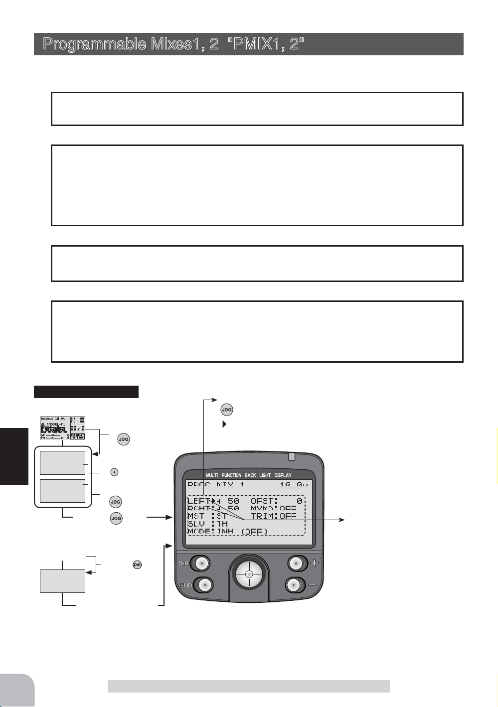
Programmable Mixes1, 2 "PMIX1, 2"
(All channel)
These functions allow you to apply mixing between the steering, throttle, and channel 3
channels.
Two programmable mixing systems can be used. The programmable mixing 1 and programmable mixing 2 set-up screens are independent.
Additional Functions
-When the steering or throttle channel is the master channel (channel that applies mixing), trim data can be added. (Trim mode)
- The mixing mode selection. (Master mixing mode)
- The master channel mixing center point (point at which the direction changes) can be
offset. (Offset function)
Movement of the slave channel side
The movement of the master channel side will be added to the movement of the
slave channel side.
When "TRG-BRK" was set to "CUT OFF" by boat mode function
When "CUT OFF", which prohibits trigger brake side operation, was set in the boat
mode (p.72), since brake side operation is shut off, when the master channel (MST) is
set to throttle, only "FWRD" side mixing is activated. "BRAK" side mixing is not activated.
Calling the setup screen
*Calling from menu screen
(Opening Screen)
Menu screen call
by button
MENU 1
MENU 2
Function
* When the direct call button is set,
the setup screen is also called by the
following method:
(Opening Screen)
DIRECT SEL
MENU1/2 selection
button
by
Select the function
by button
he button
Press t
he button
Press t
Press the button set
at this function.
•Select the setting item by
button
blinks at the current
*
setup item.
Setup items
LEFT :
RGHT :
MST :Master channel
SLV :Slave channel
MODE :Function ON/OFF
OFST :Offset
MXMD :Mix mode
TRIM : Trim mode
These setup items are different
depend on the master channel.
Upper side :
Lower side :
Adjust button
- Adjust with the (+) and (-) but-
- Return to the initial value "100"
Mixing rate (Left side)
Mixing rate (Right side)
LEFT/FWRD/UP
RGHT/BRAK/DOWN
tons.
by pressing the (+) and (-) buttons simultaneously for about 1
second.
76
Programmable Mixes1, 2 "PMIX1, 2"
Page 77

Program mixing adjustment
(Preparation)
- Use the function select switch function (page 79) to select the
switch. (as desired)
1
(Mixing function ON/OFF)
Select the setting item "MODE" by (JOG) button up, down,
left, or right operation. Press the (+) or (-) button and set the
function to the "ACT" state.
"INH" :Function OFF
"ACT" :Function ON
2
(Master channel)
Select setup item "MST" by (JOG) button up, down, left, or
right operation, and select the master channel by pressing
the (+) or (-) button.
3
(Slave channel)
Select setup item "SLV" by (JOG) button up, down, left, or
right operation, and select the slave channel by pressing the
(+) or (-) button.
Setup item selection
- Select by (JOG) button up,
down, left or right operation.
Switch
PRG MIX1 : Program mixing 1
PRG MIX2 : Program mixing 2
Function ON/OFF (MODE)
INH, ACT
Channel selection (MST)
ST, TH, CH3
Initial value :PMIX1(ST)
PMIX2(TH)
Channel selection (SLV)
ST, TH, CH3
Initial value :PMIX1(TH)
PMIX2(CH3)
4
(Left, forward or up side mixing amount adjustment)
Select the setting item "LEFT", "FWRD", or "UP" by (JOG)
button up, down, left, or right operation. Use the (+) or (-) button and adjust the right, brake, or down side mixing amount.
5
(Right, brake or down side mixing amount adjustment)
Select the setting item "RGHT", "BRAK", or "DOWN" by (JOG)
button up, down, left, or right operation. Use the (+) or (-) button and adjust the right, brake, or down side mixing amount.
6
(Offset amount setup)
Select setup item "OFS" by (JOG) button up, down, left, or
right operation, and use the (+) and (-) button to adjust the
offset amount.
7
(Mixing mode setup)
Select setup item "MXD" by (JOG) button up, down, left, or
right operation, and use the (+) or (-) button to select the
mixing mode.
"OFF" :Mixing proportional to master channel operation.
"MIX" :Mixing by master channel another function considered.
Mixing amount
-100~0~+100
Initial value: +50
Mixing amount
-100~0~+100
Initial value: +50
Offset amount (OFS)
-100~0~+100
Initial value: 0
Function
Mixing mode (MXD)
OFF, MIX
Initial value: OFF
8
(Trim mode setup)
Programmable Mixes1, 2 "PMIX1, 2"
77
Page 78

Select setup item "TRM" by (JOG) button up, down, left, or
right operation, and use the (+) or (-) button to select the
mixing mode.
"OFF" :Trim is added.
"ON" :Trim is removed.
9
When ending setting, return to the initial screen by pressing
the (END) button twice (for direct selection, press the (END)
button once).
When Steering and Throttle Travel is Insufficient
Trim mode (TRM)
OFF, ON
Initial value: OFF
When the steering servo travel is insufficient even when D/R is 100% and EPA is 120%,
programmable mixing can be used to increase the travel somewhat.
(Reference data)
- PROG NIX1->ON
- MST (master channel) -> ST Mixing is applied from steering
- SLV (slave channel) ->ST Mixing is applied to steering and the travel is increased.
- RGHT -> 10% [When subtrim is centered (0%)]
- LEFT -> 10% [When subtrim is centered (0%)]
- OFST -> 0%
A
A
- MXMD -> MIX
- TRIM -> OFF
However, the operating range of the servo is exceeded
even if a large value is input at RIGH and LEFT and a
zone over which the servo does not operate even when
the stick is moved to the left or right is created. A zone
over which the servo does not operate is also generated
at the moving side when the subtrim is moved to the left
A :Zone over which servo
does not operate
and right. Therefore, set the RIGH and LEFT value by checking servo operation.
Full rightFull left
78
Function
When the throttle servo travel is insufficient at ATL 100% and EPA120%, the same action can be performed by making TH (throttle) both the MST and SLV when steering.
When both steering and throttle operations are performed, use both PROG MIX1 and
PROG MIX2 program mixing.
Switch Setting
Select the program mixing 1,2 function ON/OFF switch with the function select switch
function. (See page 79)
Dial / Trim Setting
The mixing amount can be adjusted by using the function dial function (p.80).
Programmable Mixes1, 2 "PMIX1, 2"
Page 79

Function Select Switch "SWTCH"
This function allows selection of the function to be performed by the switches
(SW1/SW2/SW3) and setting of the direction,
etc. of operation.
-The table to the right shows the functions that
can be assigned to each push switch.
-SW1 and SW2 can be made alternate operation (ON/OFF switched each time SW
pressed).(NOR/ALT)
-The direction of operation of SW3 can be
reversed.(NOR/REV)
SW2
Calling the setup screen
*Calling from menu screen
(Opening Screen)
MENU 1
MENU 2
* When the direct call button is set,
the setup screen is also called by the
following method:
(Opening Screen)
DIRECT SEL
SW1
Menu screen call
by button
MENU1/2 selection
by
Select the function
by button
he button
Press t
Press t
button
he button
SW3
•Select the setting item by button
blinks at the current setup item.
*
Settable functions
Abbreviation used
on setup screen
AT-START Start function / Engine cut
TH-SPEED Throttle speed
A.B.S.CH2 A.B.S function (2CH)
A.B.S.CH3 A.B.S function (3CH)
D/R 2ND 2nd dual rate
IDLE-UP Idle up
PROG MIX1 Program mixing 1
PROG MIX2 Program mixing 2
CH3 channel 3
LAP STAR
LAP RESET
OFF Not used
Timer function start (SW3 not possible)
Timer function reset (SW3 not possible)
Function name, etc
Direction of operation setting
(NOR/ALT)
Function selection
(SW1/SW2/SW3)
Press the button set
at this function.
Function select switch setup
1
(Setting SW selection)
Select the item you want to set by (JOG) button up, down,
left, or right operation.
2
(To select or change a function for SW)
Select one of the functions for "SW" by pressing (+) or (-) button.
(To change the operation mode)
Select othe operation mode for "SW" by pressing (+) or (-) button.
3
When ending setting, return to the initial screen by pressing
the (END) button twice (for direct selection, press the (END)
button once).
Function Select Switch "SWTCH"
Setup item selection
- Select by (JOG) button up,
down, left or right operation.
Setup buttons
- Use the (+) and (-) buttons to
make adjustments.
- Press the (+) and (-) buttons
simultaneously (approx. 1 sec)
to return to the initial screen.
Initial value:
SW1,SW2,SW3 :"OFF", "NOR"
Function
79
Page 80

Function Select Dial "DIAL"
This function allows selection of the function performed by the digital dial (DL1/DL2/
DL3) and digital trimmers (DT1/DT2/DT3), step amount adjustment, and operating direction reversal.
- The table below lists the functions that can be assigned to each dial
and digital trimmer. The assigned function is also displayed on the
opening screen together with the current adjustment value. They are
displayed in DT1, DT2, DT3, DL1, DL2, and DL3 order, from top to bottom.
- The step amount can be adjusted. The table below shows the relationship between set value and step
amount.
- The operation direction can be reversed. (NOR/REV)
Settable functions (DL1/DL2/DL3, DT1/DT2/DT3)
Function
Abbrevia-
tion used on
setup screen
D/R (D/R) Dual rate function
ATL (ATL) ATL function
EXP-S (EXPS) Steering EXP
EXP-F (EXPF) Throttle EXP (Forward side)
EXP-B (EXPB) Throttle EXP (Brake side)
EXP-3 (EXP3) 3rd Channel brake EXP
SP-TN (SPTn) Steering speed (Turn side)
SP-RN (SPRn) Steering speed (Return side)
AB.P (AB.P) A.B.S. function (Return amount)
ABS.D (ABSD) A.B.S. function (Delay)
CYCLE (CYCL) A.B.S. function (cycle speed)
ACC-F (ACCF) Throttle acceleration (Forward side)
ACC-B (ACCB) Throttle acceleration (Brake side)
ACC-3 (ACC3) 3rd Channel brake acceration (BRAKE fanction-ON)
THSP1 (THS1) Throttle speed (ALL/LOW)
THSP2 (THS2) Throttle speed (MID)
THSP3 (THS3) Throttle speed (HIGH)
ST-TR (TRMS) Steering trim
TH-TR (TRMT) Throttle trim
CH3 (3CH) Channel 3
SUBT1 (SBT1) Sub trim (CH1)
SUBT2 (SBT2) Sub trim (CH2)
SUBT3 (SBT3) Sub trim (CH3)
D/R2 (D/R2) 2nd dual rate function
IDLUP (IDLE) Idle up function
TLT13 (TL13) Tilt mixing (1>3)
TLT31 (TL31) Tilt mixing (3>1)
PM1-A (PM1A) Program mixing 1 (RGHT/BRAK/DOWN sides)
PM1-B (PM1B) Program mixing 1 (LEFT/FWRD/UP sides)
PM2-A (PM2A) Program mixing 2 (RGHT/BRAK/DOWN sides)
PM2-B (PM2B) Program mixing 2 (LEFT/FWRD/UP sides)
BK-RT (BKRT) Brake mixing (3ch brake rate)
BK-DL (BKDL) Brake mixing (delay)
B-ABP (BABP) 3rd Channel A.B.S -Return amount (BRAKE fanction-ON)
B-ABD (BABD) 3rd Channel A.B.S -Delay(BRAKE fanction-ON)
OFF Not used
Abbreviation
displayed on
opening screen
Initially set functions
DL1 :Dual rate function
DL2 :ATL function
DL3 :(Not set)
DT1 :Steering trim
DT2 :Throttle trim
DT3 :(Not set)
Function name, etc
DT2
DL3 DT1
DL1 DL2
DT3
80
Function Select Dial "DIAL"
Page 81

Calling the setup screen
*Calling from menu screen
(Opening Screen)
Menu screen call
by
button
MENU 1
MENU 2
* When the direct call button is set,
the setup screen is also called by the
following method:
(Opening Screen)
DIRECT SEL
MENU1/2 selection
button
by
Select the function
by button
he button
Press t
he button
Press t
Press the button set
at this function.
Function select dial setup
1
(Setting Dial selection)
Select the item you want to set by (JOG) button up, down,
left, or right operation.
2
(To select or change a function for Dial)
Select one of the functions for "DIAL" by pressing (+) or (-) button.
(To change the step amount)
Use the (+) or (-) button to set the step amount.
(When changing the direction of operation)
Use the (+) or (-) button to dial the direction.
3
When ending setting, return to the initial screen by pressing
the (END) button twice (for direct selection, press the (END)
button once).
•Select the setting item by
button
blinks at the current
*
setup item.
Direction of operation setting
Step amount setting
Function selection
Setup item selection
- Select by (JOG) button up,
down, left or right operation.
Adjustment buttons
- Use the (+) and (-) buttons to
make adjustments.
- Press the (+) and (-) buttons
simultaneously (approx. 1 sec)
to return to the initial screen.
Initial value:
DL1 :"D/R", "2", "NOR"
DL2 :"ATL", "2", "NOR"
DL3 :"OFF"
DT1 :"ST-TR", "2", "NOR"
DT2 :"TH-TR", "2", "NOR"
DT3 :"OFF"
Relationship between set value and step amount
- Steering trim/throttle trim (Setting range: 1, 2, 3, 4, 5, 6, 7, 10)
When set to the minimum "1", the trim operation width is 200 clicks. When set to the maximum "100", the
trim operation width is 20 clicks.
- Rate, etc. setup (Setting range: 1, 2, 3, 4, 5, 6, 7, 10%)
The % value that is operated by 1 click relative to the set value of each rate can be set.
- Channel 3 (Setting range: 1, 2, 5, 10, 20, 50, 3PS, 2PS)
When set to the minimum "1", the channel 3 total operation width is 200 clicks. When set to "50", the channel 3 total operation width is 4 clicks. The total operation width for 3PS is 2 clicks and the total operation
width for 2PS is 1 click. 3PS acts like a 3-position switch and 2PS acts like a 2-position switch.
Function Select Dial "DIAL"
Function
81
Page 82

Timer Function "TIMER"
Use the timer by selecting one of the four timers UP TIMER, DOWN TIMER, LAP
TIMER and LAP NAVIGATE timer.
UP TIMER function
- The UP TIMER can be used to count the time between start and stop, etc.
- The timer repeatedly starts and stops each time the switch
is operated and accumulates the time between each start and
stop. (When the count reaches 99 minutes 59 seconds, it returns to 00 minutes 00 seconds and repeats the count.)
- The first start operation can be linked to the throttle trigger.
- An alarm sound can be set. The passage of time is announced by sounding of a buzzer
(beeps) each minute after starting.
- Alarm: Generates a beep at the set time (minutes).
- Prealarm: Alarm advance announcement sound. Sounding starts the set time (seconds) before the
alarm. (beeps)
- After starting, the timer is enabled and can be stopped by switch even when the display
switches to another screen.
82
DOWN TIMER function
- The DOWN TIMER can be used to count the time between start and stop, etc. (The
time remaining is displayed.)
Function
- Start and stop are repeated at each switch operation and
the time between each start and stop is counted down and
displayed. The start time becomes the alarm set time.
(When the count reaches 00 minute 00 second, the down
timer operates like an up timer.)
- The first start operation can be linked to the throttle trigger.
- An alarm sound can be set. The passage of time is announced by sounding of a buzzer
(beeps) each minute after starting.
- Alarm: Generates a beep at the set time (minute).
- Prealarm: Alarm advance announcement sound. Sounding starts the set time (seconds) before the
alarm. (beeps)
- After starting, the timer is enabled and can be stopped by switch even when the display
switches to another screen.
Timer Function "TIMER"
Page 83

LAP TIMER
LAP TIMER function
- The LAP TIMER can memorize each lap time of each switch operation. (98 laps)
- The race time can be set. Switch operation after the set
time by alarm has elapsed automatically stops the timer..
Prealarm can also be set. The passage of time is announced
by sounding of a buzzer (beeps) each minute after starting.
-Alarm: Generates a beep at the set time.
Prealarm: Starts sounding the set time (second) before the alarm. (beeps)
- The first start operation can be linked with the throttle trigger.
(LAP TIMER operation)
- When lap timer is selected, the number of laps (LAP) and the lap memory No. (No.)
and current lap time (TIME) are displayed on the setup screen.
- Number of laps (LAP): Counts up each time the switch is pressed after starting. The numbers blink
for 3 seconds after the switch was pressed. To prevent erroneous counting, switch operation is not
accepted during this period..
- Lap memory No. (No.): Each lap time is memorized in a lap memory. The lap times are written
sequentially from the number after the preceding data. After lap memory "No. 100", the lap No. returns to "No. 1".
- The lap time data memorized in the lap memory can be checked at the lap list (See p. 89) screen.
- Lap time (TIME) : During the first 3seconds, the last lap time is displayed and then the current lap
time is displayed. At starting, "0" is displayed for 3 seconds.
LAP NAVIGATE timer
LAP NAVIGATE timer function
- This function sounds a buzzer at a fixed interval after the timer starts. Since only the
buzzer can be restarted when the switch is pressed during
timer operation, this function can be used as the training
run, etc. target time. (Lap navigation alarm) The passage of
time is announced by sounding of a buzzer (beeps) every
minute after starting.
- The first start operation can be linked with the throttle
trigger.
- The alarm sounds (alarm/prealarm) can be set separately from the fixed interval buzzer.
- Alarm: Generates a beep at the set time (minutes).
- Prealarm: Alarm advance announcement sound. Sounding starts the set time (seconds) before the
alarm. (beeps)
- After starting, the timer is enabled and can be stopped by switch even when the display
switches to another screen.
Function
Timer Function "TIMER"
83
Page 84

Calling the setup screen
*Calling from menu screen
(Opening Screen)
Menu screen call
by button
MENU 1
MENU 2
* When the direct call button is set,
the setup screen is also called by the
following method:
(Opening Screen)
DIRECT SEL
MENU1/2 selection
button
by
Select the function
by button
he button
Press t
he button
Press t
Press the button set
at this function.
Operation display
While the TIMER function is operating,
menu screen.
•Select the setting item by
button
blinks at the current
*
setup item.
TIM
is displayed on the initial screen and
Timer selection
First, select the type of
timer at the "TYPE" item.
The setup screen varies
depending on the type of
timer. This figure shows the
UP TIMER setup screen.
Time display
Minute display (m)
Second display (s)
1/100 second display
Function
Racing timer type selection
(Preparation)
Assign the "LAP START" switch using the function select
switch (p.79). When resetting by switch, assign "LAP RESET"
also.
1
(Racing timer type selection)
Select the setting item "TYPE" by (JOG) button up, down,
left, or right operation. Press the (+) or (-) button and set the
racing timer type.
Timer selection (TYPE)
UP TIMER : Up timer
DOWN TIMER : Down timer
LAP MEMORY : Lap timer
LAP NAVIGATE : Navigate timer
2
When ending setting, return to the initial screen by pressing
the (END) button twice (for direct selection, press the (END)
button once).
- Read the later descriptions for the operation method by type.
Setup item selection
- Select by (JOG) button up,
down, left or right operation.
Adjustment buttons
- Use the (+) and (-) buttons to
make adjustments.
84
Timer Function "TIMER"
Page 85

Using the up timer
(Preparation)
Select the setting item "TYPE" by (JOG) button up or down
operation. Press the (+) or (-) button and select "UP TIMER".
1
(Alarm time setting)
Select the setting item "ALRM"by (JOG) button up, down,
left, or right operation and set
the alarm time with the (+) and
(-) buttons.
(Pre alarm time setting)
Select the setting item "PRAL"
by (JOG) button up, down, left, or right operation, and set the
pre alarm time with the (+) and (-) buttons.
2
(Timer start/stop operation)
When the switch ("LAP START") assigned by function select
switch function is pressed, the
timer starts. Stop the timer
with the same switch ("LAP
START") as start, or with the
switch assigned the "LAP RESET" function.
- Linking only start to the throttle trigger
Select the setting item "RST" by (JOG) button up, down, left,
or right operation and press the (+) and (-) buttons simultaneously for about 1 second. When the set beeps and the status
display switches from "RST" to blinking "RDY", the system
enters the trigger operation ready state. When the trigger is
operated at the forward side, the timer starts. (Status display
"RUN")
3
(Timer reset operation)
When the switch ("LAP RESET") assigned by function select
switch function is pressed, the
timer is reset. Select the status display ("RUN", "STP", or
"RDY") by (JOG) button up or
down operation and press the
(+) and (-) buttons simultaneously for about 1 second. The
set beeps and the status display changes to "RST" and the
timer resets.
Adjustment buttons
- Use the (+) and (-) buttons to
make adjustments.
- Press the (+) and (-) buttons
simultaneously (approx. 1 sec)
to return to the initial screen.
Alarm time (ALRM)
OFF, 1 ~ 99 m
Initial value: 8 m
Prealarm time (PRAL)
OFF, 1 ~ 30 s
Initial value: OFF
Status display
RST :Reset state
RDY :
Throttle trigger operation wait
RUN :Timer running
STP : Timer stopped
Switches
LAP START :start / stop
LAP RESET :stop / reset
Status display
RST :Reset state
RDY :
Throttle trigger operation wait
RUN :Timer running
STP : Timer stopped
Function
Timer Function "TIMER"
85
Page 86

Function
Using the down timer
(Preparation)
Select the setting item "TYPE" by (JOG) button up or down
operation. Press the (+) or (-) button and select "DOWN TIMER".
1
(Alarm time setting)
Select the setting item "ALRM"by (JOG) button up, down,
left, or right operation and set
the alarm time with the (+) and
(-) buttons.
(Pre alarm time setting)
Select the setting item "PRAL"
by (JOG) button up, down, left, or right operation, and set the
pre alarm time with the (+) and (-) buttons.
2
(Timer start/stop operation)
When the switch ("LAP START") assigned by function select
switch function is pressed, the
timer starts. Stop the timer
with the same switch ("LAP
START") as start, or with the
switch assigned the "LAP RESET" function.
- Linking only start to the throttle trigger
Select the setting item "RST" by (JOG) button up, down, left,
or right operation and press the (+) and (-) buttons simultaneously for about 1 second. When the set beeps and the status
display switches from "RST" to blinking "RDY", the system
enters the trigger operation ready state. When the trigger is
operated at the forward side, the timer starts. (Status display
"RUN")
3
(Timer reset operation)
When the switch ("LAP RESET") assigned by function select
switch function is pressed, the
timer is reset. Select the status display ("RUN", "STP", or
"RDY") by (JOG) button up or
down operation and press the
(+) and (-) buttons simultaneously for about 1 second. The
set beeps and the status display changes to "RST" and the
timer resets.
Adjustment buttons
- Use the (+) and (-) buttons to
make adjustments.
- Press the (+) and (-) buttons
simultaneously (approx. 1 sec)
to return to the initial screen.
Alarm time (ALRM)
OFF, 1 ~ 99 m
Initial value: 8 m
Prealarm time (PRAL)
OFF, 1 ~ 30 s
Initial value: OFF
Status display
RST :Reset state
RDY :
Throttle trigger operation wait
RUN :Timer running
STP : Timer stopped
Switches
LAP START :start / stop
LAP RESET :stop / reset
Status display
RST :Reset state
RDY :
Throttle trigger operation wait
RUN :Timer running
STP : Timer stopped
86
Timer Function "TIMER"
Page 87

Using the Lap timer timer
(Preparation)
Select the setting item "TYPE" by (JOG) button up or down
operation. Press the (+) or (-) button and select "LAP NEMORY".
1
(Alarm time setting)
Select the setting item "ALRM"by (JOG) button up, down,
left, or right operation and set
the alarm time with the (+) and
(-) buttons.
(Pre alarm time setting)
Select the setting item "PRAL"
by (JOG) button up, down, left, or right operation, and set the
pre alarm time with the (+) and (-) buttons.
2
(Timer start/lap count operation)
Perform the start and lap count operations with the switch
("LAP START") assigned by
function select switch function.
- Linking only start to the throttle trigger
Select the setting item "RST" by (JOG) button up, down, left,
or right operation and press the (+) and (-) buttons simultaneously for about 1 second. The set beeps and the timer display
changes from "RST" to blinking "RDY" and the set enters the
trigger operation ready state. (Status display "RUN")
3
(Timer stop/reset operation)
When the lap count switch ("LAP START") is pressed after
the time set with "ALRM" has
elapsed, the timer stops and
the lap time, total time, and average time are memorized.
When the switch ("LAP RESET") is pressed, the timer is reset.
When a switch is not assigned, select the status display
("RUN", "STP", or "RDY") by (JOG) button up or down operation and press the (+) or (-) buttons simultaneously for about
1 second. The set beeps and the timer display changes to
"RST" and the timer resets.
- When the timer was stopped with the switch assigned the “LAP RESET”
function before the set “ALRM” time has elapsed, the total time and average time are not memorized.
Adjustment buttons
- Use the (+) and (-) buttons to
make adjustments.
- Press the (+) and (-) buttons
simultaneously (approx. 1 sec)
to return to the initial screen.
Alarm time (ALRM)
OFF, 1 ~ 99 m
Initial value: 8 m
Prealarm time (PRAL)
OFF, 1 ~ 30 s
Initial value: OFF
Status display
RST :Reset state
RDY :
Throttle trigger operation wait
RUN :Timer running
STP : Timer stopped
Switches
LAP START :start / lap count
LAP RESET :stop / reset
Status display
RST :Reset state
RDY :
Throttle trigger operation wait
RUN :Timer running
STP : Timer stopped
Function
Timer Function "TIMER"
87
Page 88

Function
Using the navigate timer
(Preparation)
Select the setting item "TYPE" by (JOG) button up or down
operation. Press the (+) or (-) button and select "NAVIGATE".
1
(Alarm time setting)
Select the setting item "ALRM"
by (JOG) button up, down, left, or
right operation and set the alarm
time with the (+) and (-) buttons.
(Pre alarm time setting)
Select the setting item "PRAL" by (JOG) button up, down, left, or right
operation and set the pre alarm time with the (+) and (-) buttons.
(Lap navigation time setting)
Select the setting item "NAVI" by (JOG) button up, down, left,
or right operation and set the lap navigation alarm (target)
time with the (+) and (-) buttons.
2
(Timer start/navigation restart operation)
When the switch ("LAP START") assigned by function select
switch function is pressed, the
timer starts.
- Linking only start to the throttle trigger
Select the setting item "RST" by (JOG) button up, down, left,
or right operation and press the (+) and (-) buttons simultaneously for about 1 second. The set beeps and the status displays changes from "RST" to blinking "RDY" and the set enters
the trigger operation ready state. When the trigger is operated
at the forward side, the timer starts. (Status display "RUN")
- When your own lap time is less than the target time and the lap counts
overlap, the lap navigation alarm timing is too big. The alarm timing can
be corrected by pressing the switch ("LAP START") during measurement.
Adjustment buttons
- Use the (+) and (-) buttons to
make adjustments.
- Press the (+) and (-) buttons
simultaneously (approx. 1 sec)
to return to the initial screen.
Alarm time (ALRM)
OFF, 1 ~ 99 m
Initial value: 8 m
Prealarm time (PRAL)
OFF, 1 ~ 30 s
Initial value: OFF
Navi alarm time (NAVI)
OFF, 1 ~ 30 s
Initial value: 3 s
Status display
RST :Reset state
RDY :
Throttle trigger operation wait
RUN :Timer running
STP : Timer stopped
Switches
LAP START :start/navi restart
LAP RESET :stop/reset
88
3
(Timer stop/reset operation)
When the switch ("LAP RESET") assigned by function select switch function is pressed,
the timer stops. Reset the
timer by pressing the "LAP
RESET" switch.
When a switch is not assigned, select the status display
("RUN" or "RDY") by (JOG) button up or down operation and
press the (+) and (-) buttons simultaneously for about 1 second. The set beeps and the timer resets. (Does not pause)
Timer Function "TIMER"
Status display
RST :Reset state
RDY :
Throttle trigger operation wait
RUN :Timer running
STP : Timer stopped
Page 89

Lap List "LAP-L"
Call LAP-LIST when checking the lap memory data (each lap time) memorized by lap
timer (page 87 ) operation.
- After the lap timer is started, the lap time is sequentially memorized at each switch operation.
When set time of ALRM passes and the timer is stopped, the last lap is memorized and
the total time is automatically written after the last lap and the average lap is automatically written after that.
-The next Lap-Timer starts at the lap memory number following the average lap (AVE).
Calling the setup screen
*Calling from menu screen
(Opening Screen)
Menu screen call
by button
MENU 1
MENU 2
* When the direct call button is set,
the setup screen is also called by the
following method:
(Opening Screen)
DIRECT SEL
MENU1/2 selection
by
Select the function
by button
he button
Press t
Press t
button
he button
Lap memory No. display
Lap time display
In addition to the lap time, the total time and average lap time are
memorized in the lap memory
after the last lap time.
"LAP" represents the lap time,
"TOTAL" represents the total
time, and "AVE" represents the
average lap.
Press the button set
at this function.
Using the lap memory
1
(Lap memory check)
The cursor can be scrolled and each lap time checked by
(JOG) button up or down operation.
2
(Lap memory reset)
Select the lap memory No. by (JOG) button up or down operation and press the (+) and (-) buttons simultaneously for
about 1 second. The set beeps and the lap memory of the
selected lap memory No. resets.
(Resetting all the lap memory data)
While pressing the (JOG) button, press the (+) and (-) buttons simultaneously for about 1 second. The set beeps and
all the data resets.
3
When ending setting, return to the initial screen by pressing
the (END) button twice (for direct selection, press the (END)
button once).
Function
Lap List "LAP-L"
89
Page 90

Model Selection "M-SEL"
Use this function to call a new model # or an existing model # to set new model data.
The T3PKS transmitter can store the model data for 20 R/C cars. The CAMPac-16K
(option) can store the model data for 10 more models.
The model numbers are "M1" to "M20" at the transmitter and "E21" to "E30" at the
CAMPac-16K. When the CAMPac-16K is not installed, "E21" to "E30" are not displayed.
Calling model memories of different modes (HRS, PCM, or PPM mode)
After a model memory was called, signals are output in the mode before the model
memory was called until the transmitter power is turned off. Use the transmitter after
turning the power off and then back on.
CAMPac-16K (option)
When using the CAMPac-16K, operation must be initialized so that the CAMPac-16K
can be used with this transmitter. When "INITIALIZE?" appears on the screen at powering ON, press the (+) button. This automatically initializes operation. This action is
unnecessary thereafter.
Inserting and removing the DataPac
Insert and remove the CAMPac-16K with the transmitter power turned off. If the power
is turned off and the DataPac is removed when a CAMPac-16K model number (E21 to
E30) was selected and the power is turned back on while the CAMPac-16K is removed
and any button is pressed after "SELECT ERROR" is displayed, model number M1 is
forcefully selected.
Calling the setup screen
*Calling from menu screen
(Opening Screen)
Function
MENU 1
MENU 2
Press t
* When the direct call button is set,
the setup screen is also called by the
following method:
(Opening Screen)
DIRECT SEL
Menu screen call
by
MENU1/2 selection
button
by
Select the function
by button
he button
he button
Press t
Select the model # by (JOG) button
button
Current model # and model name
90
Press the button set
at this function.
Model Selection "M-SEL"
Page 91

Using the model selection function
1
(Model No. selection)
Select the model No. by (JOG) button up, down, left, or right
operation. The DataPac models are displayed from the cursor position of "M1" to "M5" on
the top row of the transmitter
model by (JOG) button up operation or from the cursor position of "M16" to "M20" on the
bottom row of the transmitter
model by (JOG) button down
operation.
The same operation is performed
when the transmitter model is
displayed from the DataPac
model.
- The model No. and model name of the model to be modified are displayed at the bottom right-hand side of the screen.
2
(Model selection execution)
(Screen displaying the DataPac models)
Press the (+) and (-) keys
simultaneously for about 1
second. The set beeps and the
model is selected.
Displays "DPAC" when the
CAMPac-16K is installed in the
transmitter.
Model # and model name currently operating
Model # and model name to be
modified
Model No.
M1~M20 :Model memory in the
Transmitter
E21~E30 :Model memory in the
CAMPac-16K
Model selection button
- Select the model by (JOG) button
up, down, left, or right operation.
Modified model # and model
name
- When the model # and model name at the bottom left-hand side of the
screen change, model selection is complete.
3
When ending setting, return to the initial screen by pressing
the (END) button twice (for direct selection, press the (END)
button once).
Model Selection "M-SEL"
Model selection set button
- (+) and (-) buttons pressed
simultaneously for about 1 second.
Function
91
Page 92

Model Name "NAME"
This function allows you to assign a ten character name to each model memory and an
user name (ten character).
Calling the setup screen
*Calling from menu screen
(Opening Screen)
Menu screen call
by
button
MENU 1
MENU 2
* When the direct call button is set,
the setup screen is also called by the
following method:
(Opening Screen)
DIRECT SEL
MENU1/2 selection
button
by
Select the function
by button
he button
Press t
he button
Press t
Press the button set
at this function.
Setting the model name and user name
1
(Moving the cursor to the character you want to change)
Move the cursor to the model name or user name character
you want to set or change by pressing the (+) or (-) button.
The selected character blinks.
Select the character with the
(JOG) button. The selected character blinks.
User name
Model name
*The character at the blink-
ing cursor position can be
changed. The model name and
user name can both use up to
10 characters.
When a character is entered by
pressing the (JOG) button, the
model name and user name
cursors move to the right.
92
Function
2
(Selecting the character to be used)
Select the character to be used from the character list at the
right-hand side of the screen by (JOG) button up, down, left,
or right operation. The selected character blinks. After selecting the character to be used, press the (JOG) button. The
character is entered and the model name or user name character row moves to the right.
When "RESET" on the top row of the character list is selected and the (JOG) button is pressed, the model name or user
name is initialized to the factory setting.
3
When ending setting, return to the initial screen by pressing
the (END) button twice (for direct selection, press the (END)
button once).
Model Name "NAME"
Character select/set button
- Select the character by (JOG)
button up, down, left, or right
operation and enter the character by pressing the (JOG)
button.
Initialization
Model name :MODEL-M(No)
User name :FUTABA-3PK
Page 93

Model Copy "M-COP"
This function calls the contents of one model memory to another model memory.
Single mode (SINGLE) and group mode (GROUP)
Single mode copies data to another model in model units.
Group mode makes the data of model memories M1 to M10 and M11 to M20, and DataPac model memories E21 to
E30 individual groups and copies the data from group to group. For example, this function is convenient when copying
the data of T3PKS transmitter model memories M1 to M10 to DataPac model memories E21 to E30 in a batch.
Calling the setup screen
*Calling from menu screen
(Opening Screen)
Menu screen call
by
button
MENU 1
MENU 2
* When the direct call button is set,
the setup screen is also called by the
following method:
(Opening Screen)
DIRECT SEL
MENU1/2 selection
by
Select the function
by button
he button
Press t
Press t
button
he button
•Select the setting item by
button
blinks at the current
*
setup item.
Current model # and model name
Copy destination model # and
model name
Press the button set
at this function.
Model copying
(Preparation)
Select the setting item "MODE" by (JOG) button up or down op
eration and select "SINGLE" or "GROUP" by pressing the (+) or (-)
button.
1
(Copy source model No. selection)
Select the setting item "MST" by (JOG) button up or down operation. Press the (+) or (-) button and select the model #.
2
(Copy destination model No. selection)
Select the setting item "SLV" by (JOG) button up or down operation. Press the (+) or (-) button and select the model #.
- For the model currently in use (including group), "NOT POSSIBLE" blinks at
the bottom of the screen to alert the operator that the model cannot be copied.
3
(Copy execution)
Select the setting item "EXEC" by (JOG) button up or down
operation. Press the (+) and (-) buttons simultaneously for 1
second.
complete.
When "COMPLETE!" blinks at the bottom of the screen, copying is
(Screen with group mode selected)
Setup item selection
- Select by (JOG) button up or
-
down operation.
Model number selection
- Use the (+) and (-) buttons to
make adjustments.
Model No.
M1~M20 :Model memory in the
Transmitter
E21~E30 :Model memory in the
CAMPac-16K
Copy execution button
- (+) and (-) buttons pressed
simultaneously for about 1 second.
Function
4
When ending setting, return to the initial screen by pressing the (END)
button twice (for direct selection, press the (END) button once).
Model Copy "M-COP”
93
Page 94

Model Reset "M-RES"
This function resets the contents of the currently called model memory.
The reset method can be selected from among the 3 types described below. These resets
do not initialize the adjuster function (ADJST), system function (SYSTM), lap reset
(LAP-L), user name (NAME), and modulation (HRS/PCM/PPM) selection function (PMOD).
DATA RESET
Initializes only the function setting data. The menu function and direct selection function are not initialized.
MENU RESET
Initializes the menu function and direct selection function. Other settings are not initialized.
ALL RESET
Initializes the menu function, direct selection function, and the setting data of each function.
Calling the setup screen
*Calling from menu screen
(Opening Screen)
Menu screen call
by
button
MENU 1
MENU 2
* When the direct call button is set,
the setup screen is also called by the
following method:
(Opening Screen)
DIRECT SEL
MENU1/2 selection
by
Select the function
by button
he button
Press t
Press t
button
he button
•Select the setting item by
button
blinks at the current
*
setup item.
Current model #
94
Function
Press the button set
at this function.
Model Reset
Select the setting item "TYPE" by (JOG) button up or down
operation and press the (+) or (-) button and select the reset
type from among "DATA RESET", "MENU RESET", and "ALL
RESET".
1
(Reset execution)
Select the setting item "EXEC" by (JOG) button up or down
operation.
Press the (+) and (-) buttons simultaneously for 1 second.
When "COMPLETE!" blinks at the bottom of the screen,
memory resetting is complete.
2
When ending setting, return to the initial screen by pressing the (END)
button twice (for direct selection, press the (END) button once).
Model Reset "M-RES"
Setup item selection
- Select by (JOG) button up or
down operation.
Reset type selection
- Use the (+) and (-) buttons to
make adjustments.
Type (TYPE)
DATA RESET
MENU RESET
ALL RESET
Reset execution button
- (+) and (-) buttons pressed
simultaneously for about 1 second.
Page 95

Menu Type Selection "MENU-T"
The function selection menu matched to the level of use can be selected from among the
4 types shown below. (The menu type can be set for each model.)
LEVEL1
Caution when lowering the level
The set value of the functions removed from the menu when the level was lowered remains effective thereafter. Before lowering the level, turn off the unused functions, and
when there is rate adjustment, etc. related to other functions, check the set values.
Calling the setup screen
*Calling from menu screen
(Opening Screen)
Menu screen call
by button
MENU 1
MENU 2
MENU1/2 selection
button
by
Select the function
by button
•Select the setting item by
button
blinks at the current
*
setup item.
Menu type to be modified
Current set menu type
LEVEL3BIGCARLEVEL2
he button
Press t
* When the direct call button is set,
the setup screen is also called by the
following method:
(Opening Screen)
DIRECT SEL
Press the button set
at this function.
Press t
he button
Type selection
1
(Menu type selection)
Select the setting item "TYPE" by (JOG) button up or down operation. Select the menu type with the (+) or (-) button.
2
(Menu type change)
Select the setting item "EXEC" by (JOG) button up or down operation. Press the (+) and (-) buttons simultaneously for 1 second. When
the screen display changes, the change is complete.
3
When ending setting, return to the initial screen by pressing the (END)
button twice (for direct selection, press the (END) button once).
Menu Type Selection "MENU-T"
When "BIGCAR" is selected,
brake mixing function (p.70 CH3
brake rate (BKRT) adjustment
is automatically assigned to dial
DL3. Brake mixing function ON
is set with the brake mixing function. DL3 assignment remains
unchanged even if the type is
changed.
Type (TYPE)
LEVEL1, LEVEL2, BIGCAR, LEVEL3
Type change button
- (+) and (-) buttons pressed
simultaneously for about 1 second.
Function
95
Page 96

Direct Call Selection Button "DCALL"
The function setup screen can be called from the menu screen or quickly called by using
this direct call method. Adjustment can be made quickly by setting frequently used functions at direct call.
- Functions can be freely assigned to buttons 1~8 of the screen shown below.
- In the initial screen state, after the (DIR) button being pressed, the setup screen is
called by simply pressing the assigned button.
Call the direct Selection
screen by pressing the
button.
(Opening Screen)
press the button to
return to the Start Screen
INITIAL SETTING
Upon your needs, select one of
the 6 functions and then click its
button to call the Function Set-up
Screen.
(Direct Selection Screen)
press the button to return
to the Direct Selection Screen
Direct
No
1.
(Function Set-up Screen)
Button
Press
Function ab-
breviation
EPA
The screen on the
left shows an example of
EXP
Press the
button to return to
the Start Screen
Throttle
function.
Function
Chanel End
Point Adjuster
96
Function
2.
3.
4.
Press
7
5.
6.
7.
1
2.3.4.5.6
8
8.
Direct Call Selection Button "DCALL"
Press
Press
STSPD
STEXP
SUBTR
THEXP
THSPD
M-SEL
A.B.S
Steering Speed
Steering EXP
Subtrim
Throttle EXP
Throttle Speed
Model Select
A.B.S
Page 97

Calling the setup screen
*Calling from menu screen
(Opening Screen)
Menu screen call
by button
MENU 1
MENU 2
* When the direct call button is set,
the setup screen is also called by the
following method:
(Opening Screen)
DIRECT SEL
MENU1/2 selection
button
by
Select the function
by button
he button
Press t
he button
Press t
Press the button set
at this function.
Direct selection function assignment
1
(Direct button selection)
Select the setting item (direct button No.1~8) by (JOG) button up or down operation.
2
(Assignment function selection)
Select the assignment function by pressing the (+) or (-) button.
3
When ending setting, return to the initial screen by pressing
the (END) button twice (for direct selection, press the (END)
button once).
•Select the setting item by button
blinks at the current setup item.
*
Setup items
1: Function assigned to button No. 1
2: Function assigned to button No. 2
3: Function assigned to button No. 3
4: Function assigned to button No. 4
5: Function assigned to button No. 5
6: Function assigned to button No. 6
7: Function assigned to button No. 7
8: Function assigned to button No. 8
7
1
8
2.3.4.5.6
Direct button selection
- Select by (JOG) button up or
down operation.
Function setting button
- Set with the (+) and (-) buttons.
- Press the (+) and (-) buttons si-
multaneously. Function assignment returns to the initial value
in about 1 second.
The setup screen of this function is called by pressing the
(DIR) button for 3 seconds or longer from the initial screen.
However, when the setup screen was called by this method,
return to the initial screen by pressing the (END) button and
(DIR) button one time each, in that order.
Direct Call Selection Button "DCALL"
Function
97
Page 98

System Functions "SYSTM"
The graphic liquid crystal screen display mode, buzzer sound, LED display mode and
initial screen display mode can be set.
The system function setup items cannot be set for each model.
- Liquid crystal screen backlighting display mode setup (OFF, ON at button operation, normally ON)
- Setting of ON time (1~30 secs) when [ON at button operation] was selected above.
- Liquid crystal screen contrast adjustment (20 steps)
- Buzzer sound tone adjustment (OFF, 100 steps)
- LED display color setup (OFF, 7 colors)
- Initial screen display mode setting ("Futaba" display, timer display, servo display, Users name, trim/dial)
(Futaba)
When "Futaba", "TIMER",
"SRV-VIEW", or "USR-NAME"
was selected, this part is displayed.
- The power off forgotten alarm setting (OFF, 10 m)
Calling the setup screen
*Calling from menu screen
(Opening Screen)
Menu screen call
by
button
MENU 1
MENU 2
Function
* When the direct call button is set,
the setup screen is also called by the
following method:
(Opening Screen)
DIRECT SEL
MENU1/2 selection
by
Select the function
by button
he button
Press t
Press t
button
he button
Model
name
When "TRM/DIAL" was selected,
the trim DT1, DT2, and DT3 and
dial DL1, DL2, and DL3 information is enlarged and displayed.
•Select the setting item by
button
blinks at the current
*
setup item.
(TRM/DIAL)
RF display
When signals are being transmitted, "RF"is displayed. When
signals are not being transmitted,
"DISP" is displayed.
Modulation display
The mode currently operating is
displayed. ("PPM"/"PCM"/"HRS")
Memory module display
When the CAMPac-16K is installed, "DPAC" is displayed.
Setup items
LHT-MODE :Backlighting mode
LHT-TIME :Backlighting time
CONTRAST:Contrast
BUZ-TONE :Buzzer tone
LED-MODE :LED color
DISP-SEL :Initial screen mode
OPE-TIME :Power off forgotten alarm
LHT-MODE
LHT-TIME
MENU 1
CONTRAST
BUZ-TONE
LED-MODE
98
Press the button set
at this function.
DISP-SEL
MENU 2
OPE-TIME
Setting item selection
The items move in the order
shown in the figure above.
System Functions "SYSTM"
Page 99

System function setup
1
(Setting the liquid crystal backlighting mode)
Select the setting item "LHT-MODE" by (JOG) button up or down
operation, and select the mode by pressing the (+) or (-) button.
"KEY-ON" :Fixed time backlighting ON after button operated.
"ALWAYS" :Backlighting always ON
"OFF" :Backlighting OFF
(Setting liquid crystal backlighting time)
Select the setting item "LHT-TIME" by (JOG) button up or down
operation, and use the (+) and (-) buttons to set the ON time.
- When "KEY-ON" is set at the preceding item, this ON time becomes effective
(Adjusting the liquid crystal contrast)
Select the setting item "CONTRAST" by (JOG) button up or
down operation, and use the (+) and (-) buttons to adjust the
screen contrast.
- Adjust to an easy-to-see contrast.
(Adjusting the buzzer tone)
Select the setting item "BUZ-TONE" by (JOG) button up or down
operation, and use the (+) and (-) buttons to adjust the tone.
- Decide by referring to the tone at adjustment.
(Changing the LED display color)
Select the setting item "LED-MODE" by (JOG) button up or
down operation, and use the (+) and (-) buttons to select the
color.
- Select your favorite color while viewing the LED color.
(Changing the initial screen display mode)
Select the setting item "DISP-SEL" by (JOG) button up or down
operation, and use the (+) and (-) buttons to select the display
mode.
"Futaba" :"Futaba" logo is displayed on the initial screen.
"TIMER" :Timer screen is displayed on the initial screen.
"SRV-VIEW" :Servo operation graph is displayed on the initial screen.
"USR-NAME" :User name
"TRM/DIAL" :The trim and dial information is enlarged and displayed on
the initial screen.
(Changing the power off forgotten alarm setting)
Select the setting item "OPE-TIME" by (JOG) button up or down
operation, and use the (+) and (-) buttons to select the The power off forgotten alarm mode.
"10m" :If an operation is not performed within 10 minutes while the
power is on, an audible alarm sounds.
"OFF" :Power off forgotten alarm setting OFF
Adjustment buttons
- Use the (+) and (-) buttons to
make adjustments.
- Press the (+) and (-) buttons
simultaneously (approx. 1 sec)
to return to the initial screen.
Backlight mode (LHT-MODE)
KEY-ON, ALWAYS, OFF
Backlighting time (LHT-TIME)
1~30
Initial value: 10
.
Contrast (CONTRAST)
-10~0~+10
Initial value: 0
Buzzer tone (BUZ-TONE)
OFF, 1~75~100
Initial value: 75
LED color (LED-MODE)
(OFF), BLUE, RED, PURPLE,
GREEN, SKY BULUE, ORANGE, PINK
After reset :ORANGE
Initialization :PURPLE
Initial screen mode (DISP-MODE)
Futaba, TIMER,SRV-VIEW,
USR-NAME, TRM/DIAL
Function
The power off forgotten alarm
(OPE-TIME)
10m, OFF
2
When ending setting, return to the initial screen by pressing the
(END) button twice (for direct selection, press the (END) button
once).
System Functions "SYSTM"
99
Page 100

HRS ESC Setup "MCSET"
This function is used only when using an ESC like that shown below with a high response system (HRS System). This function is not used when using a Futaba ESC.
The frame rate of the transmitter output signal at setup may be counted and the
setup mode forcefully ended after a fixed time has elapsed, depending on the commercially available ECS. If such an ECS is used with the high response system, the
setup time will be substantially shortened and ECS setup may become difficult.
When you have an FM receiver or PCM receive, only amp setup is possible in the
PPM or PCM mode.
When using this function to make adjustments, the ECS must be directly connected to
the transmitter. Also, the following connection cords are necessary.
- Two-way cord (Must be bought separately.)
- DSC cord (Supplied with set.)
Calling the setup screen
*Calling from menu screen
(Opening Screen)
Function
MENU 1
MENU 2
Press t
* When the direct call button is set,
the setup screen is also called by the
following method:
(Opening Screen)
DIRECT SEL
Press the button set
at this function.
00
This screen does not appear except when the DSC
cord is connected or set to ON by display switch.
Menu screen call
by button
MENU1/2 selection
button
by
Select the function
by button
he button
he button
Press t
HRS ESC Setup "MCSET"
 Loading...