


PRO-RANGE 30”- 36” FULL GAS
INSTALLATION INSTRUCTIONS INSTRUCTIONS D’INSTALLATION INSTRUCCIONES PARA LA INSTALACIÓN
Dear Customer,
Thank you for purchasing one of our Accento ranges. This range was conceived, designed and handcrafted in Italy.
Your selection of a Accento range confirms you are among a special group who share a love and passion for cooking. This unique community shares in the experience of creating quality dishes; dishes that will satisfy the palate while bringing the warmth of families and friends together to share and rejoice. Impress a loved one with your ability to combine flavours and ingredients or experiment with new foods and different culinary techniques to create unexpected pleasures.
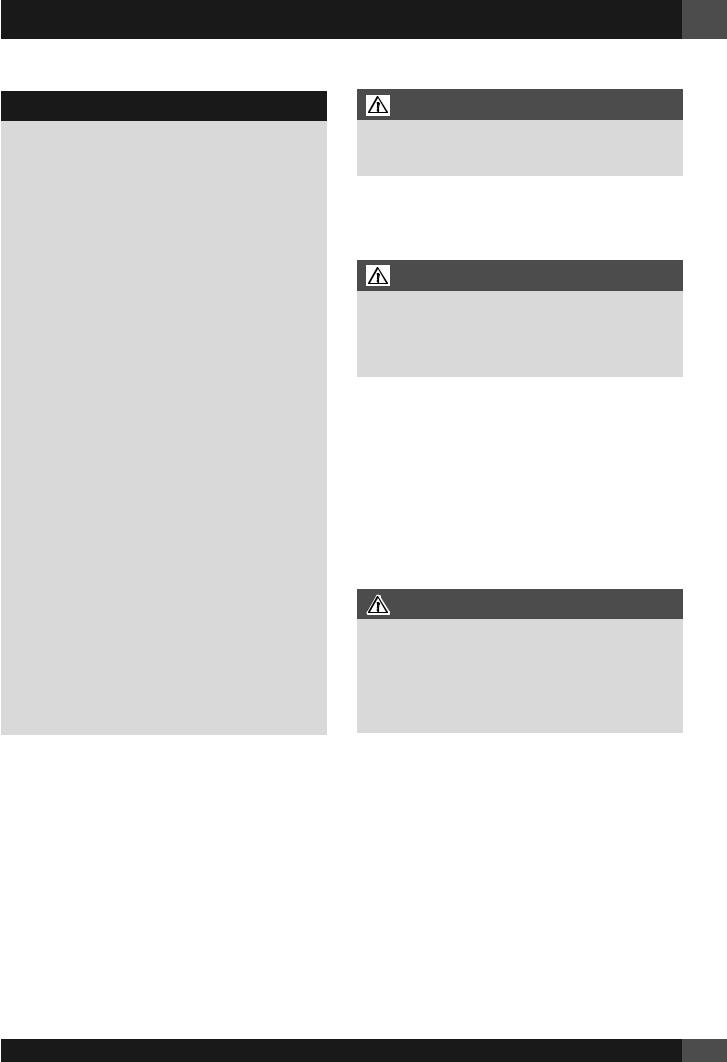
TABLE OF CONTENTS |
PAGE |
1 - Special Warnings |
2 |
Before Starting Installation |
2 |
Mobile Home Installation |
2 |
Recreational Park Trailers |
2 |
2 - Product Dimensions and Cutout Requirements |
3 |
Anti-Tip Bracket Installation |
5 |
3 - Installation Information |
6 |
4 - Installation Instructions |
7 |
5 - Gas Requirement |
11 |
Pressure Testing |
12 |
Pressure Test Method |
12 |
Gas Connection |
13 |
6 Conversion for LP or NG Gas |
14 |
Converting Appliance for Use with LP Gas |
14 |
Replace Injectors (two ring flame burner) |
14 |
Replace injector on (one ring flame or burners) |
14 |
Replace injector on (oven lower burner) |
15 |
Converting Appliances for Use with NG Gas |
17 |
Pressure regulator conversion |
17 |
INJECTORS POSITION |
18 |
Low Flame Adjustment |
20 |
Adjustment for Burners with one or two flame |
|
rings: |
20 |
Electric Gas Ignition |
21 |
The Burner Flames |
21 |
7 - Electrical Requirements |
22 |
General Information |
22 |
Electrical Connection |
22 |
Electrical Requirements |
23 |
EN
Pay attention to these symbols present in this manual:
DANGER
You can be killed or seriously injured if you don’t IMMEDIATELY follow instructions.
WARNING
This is the safety alert symbol. This symbol alerts you to potential hazards that can kill or hurt you and others. You can be killed or seriously injured if you don’t follow these instructions.
READ AND SAVE THESE INSTRUCTIONS.
To installer:
Leave these instructions with the appliance.
To customer:
Retain these instructions for future reference.
WARNING
If the information in this manual is not followed exactly, a fire or explosion may resulting in product and property damage and / or personal injury or death.
Do not store or use gasoline or other flammable vapours and liquids in the vicinity of this or any other appliance.
IMPORTANT: Save these instructions for the local electrical inspector use.
INSTALLER: Please leave this manual with owner for future reference.
OWNER: Please keep this manual for future reference.
GLOSSARY OF TERMS: NG - Natural Gas
LP - Liquid Propane
1
EN 1 - Special Warnings
IMPORTANT INSTRUCTION
Please read all instructions before using this appliance.
Proper installation is your responsibility. Have a qualified technician install this range.
IMPORTANT
-Observe all governing codes and ordinances.
-Write down the model and serial numbers before installing the range. Both numbers are on the serial rating plate refer to the illustration below.
LOCATION OF RATING PLATE
Before Starting Installation
•Check location where range will be installed. The location should be away from strong drafty areas, such as windows, doors and strong heating vents or fans.
•Electrical grounding is required. See “Electrical Requirements”
•Assure that electrical installation is adequate and in conformance with National Electrical Code, ANSI/ NFPA 70 - latest edition**, or Canadian Electrical Code, part 1 C22.1 (latest edition)*** and all local codes and ordinances.
•Assure that gas connection conforms with local codes and ordinances. In the absence of local codes, installations must conform with American National Standard, National Fuel Gas Code ANSI Z223/NFPA 54 - latest edition** Canadian CAN/ CGA_B 149.1 or CAN/CGA-149.2 latest edition**
Copies of the standards listed may be obtained from:
**National Fire Protection Association One Batterymarch Park Quincy, Massachusetts 02269
***CSA International 8501 East Pleasant Valley Rd. Cleveland, OH 44131-5575
NOTE: This range is manufactured for use with Natural gas or Propane.
To convert to LP (propane) or NG (natural gas), see instructions in the gas conversion kit provided in the literature package. Proper gas supply connection must be available. See gas supply requirements.
WARNING
Before connecting the appliance to the gas supply line, ensure that its gas setting is appropriate.
The type of gas adjusted and shipped from the factory is indicated on the rating plate.
Mobile Home Installation
The installation of this appliances must conform to the Manufactured Home Construction and Safety Standards, Title 24 CFR, Part 3280 (formerly the Federal Standard for Mobile Home Construction and Safety; Title 24 HUD part 280); or when such standard is not applicable, the Standard for Manufactured Home Installations (Manufactured Home Sites, Communities and Setups), ANSI A225.1 - latest edition, or with local codes.
In Canada, the installation of this appliances must conform with the current standards CAN/CSA-Z240 - latest edition, or with local codes.
Recreational Park Trailers
The installation of this appliances designed for Recreational Park Trailers must conform with state or other codes or, in the absence of such codes, with the Standard for Recreational Park Trailers, ANSI A119.5.
2
2 - Product Dimensions and Cutout Requirements EN
|
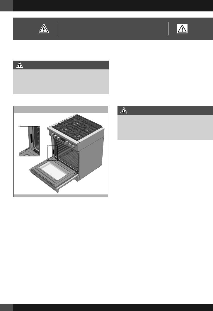
PRODUCT DIMENSIONS |
30” Wide Range Models |
36” Wide Range Models |
29 3/4” (75.8)
35 3/4”(91.0)
 29 3/4” (75.6)
 28 1/4” (719)
7” (17.9)
9" (22.8) [optional]
3" ( 7.6) [optional]
1" ( 2.5)
Max. 37 1/4” (94.7)
Min. 35 3/8” (89.8)
3/8” (1)
1 3/8” (3.5)
TO
3 3/8” (8.5)
 25 3/4” ( 65.4)
 27 1/4” ( 69.1)
 47 3/4” (121.4)
3
EN 2 - Product Dimensions and Cutout Requirements
CUTOUT REQUIREMENTS
|
|
|
|
|
|
|
|
|
|
|
|
|
|
|
|
|
|
|
|
|
|
|
|
|
|
|
|
|
|
|
|
|
|
|
|
|
|
|
|
|
|
|
|
|
|
|
|
||||
|
|
|
|
|
|
|
|
|
|
|
|
|
|
|
|
|
|
|
|
|
|
C |
|
|
|
|
|
|
|
|
|
|
|
|
|
|
|
|
|
|
|
Max. 13” (33) |
|||||||||
|
|
|
|
|
|
|
|
|
|
|
|
|
|
|
|
|
|
|
|
|
|
|
|
|
|
|
|
|
|
|
|
|
|
|
|
|
|
|
|||||||||||||
|
|
|
|
|
|
|
|
|
|
|
|
|
|
|
|
|
|
|
|
|
|
|
|
|
|
|
|
|
|
|
|
|
|
|
|
|
|
|
|
|
|
|
|
||||||||
|
|
|
|
|
|
|
|
|
|
|
|
|
|
|
|
|
|
|
Min. 30” (76.2) |
|
|
|
|
Min. 48” (122) |
|
|
|
|
|
||||||||||||||||||||||
|
|
|
|
|
|
|
|
|
|
|
|
|
|
|
|
|
|
|
To bottom of |
|
|
|
|
|
|
Minimum |
|
|
|
|
|
|
|
|
|
|
|
|
|
|
|
|
|||||||||
|
|
|
|
|
|
|
|
|
|
|
|
|
|
|
|
|
|
|
ventilation hood |
|
|
|
to Combustibles |
|
|
|
|
|
|
|
|
|
|
|
|
|
|
|
|
||||||||||||
|
|
|
|
|
|
|
|
Min.18” |
|
(45.7) |
|
|
|
|
|
|
|
|
|
|
|
|
|
|
|
|
|
|
|
Min. 18” |
|
(45.7) |
|
||||||||||||||||||
|
|
|
|
|
|
|
|
|
|
|
|
|
|
|
|
|
|
|
|
|
|
|
|
|
|
|
|
|
|||||||||||||||||||||||
|
|
|
|
|
|
|
|
|
|
|
|
|
|
|
|
|
|
|
|
|
|
|
|
|
|
|
|
|
|
|
|
|
|
|
|
|
|
|
|
|
|
|
|
|
|
|
|
|
|
|
|
|
|
|
|
|
|
|
|
|
|
|
|
|
|
|
|
|
|
|
|
|
|
|
|
|
|
|
|
|
|
|
|
|
|
|
|
|
|
|
|
|
|
|
|
|
|
|
|
|
|
|
|
|
|
|
|
|
|
|
|
|
|
|
|
|
|
|
|
|
|
|
|
|
|
|
|
|
|
|
|
|
|
|
|
|
|
|
|
|
|
|
|
|
|
|
|
|
|
|
|
|
|
|
|
|
|
|
|
|
|
|
|
|
Min. 6” |
|
|
|
|
|
|
|
|
|
|
|
|
|
|
|
|
|
|
|
|
|
|
|
|
|
|
|
Min. 6” |
|
|
||||||||||||
|
|
|
|
|
|
|
|
|
|
|
|
|
A |
|
|
|
|
|
|
|
|
|
|
|
|
|
|
|
|
|
|||||||||||||||||||||
(15.2) |
|
|
|
|
|
|
|
|
|
|
|
|
|
3” (7.6) |
(15.2) |
|
|
|
|
|
|
|
|||||||||||||||||||||||||||||
|
|
|
|
|
|
|
|
|
|
|
|
|
|
|
|
|
|
|
|
|
|
|
|
||||||||||||||||||||||||||||
|
|
|
|
|
|
|
|
|
|
|
|
|
|
|
|
|
|
|
|
|
|
|
|
|
|
|
|
|
|
|
|
|
|
|
|
|
|
|
|
|
|
|
|
|
|
||||||
|
|
|
|
|
|
|
|
|
|
|
|
|
|
|
|
|
|
|
|
|
|
|
|
|
|
|
|
|
|
|
|
|
|
|
|
|
|
|
|
|
|
|
|
|
|
||||||
|
|
|
|
|
|
|
|
|
|
|
|
|
|
|
|
|
|
|
|
|
|
|
|
|
|
|
|
|
|
|
|
|
|
|
|
|
|
|
|
|
|
|
|
|
|
||||||
|
|
|
|
|
|
|
|
|
|
|
|
|
|
|
|
|
|
|
|
|
|
|
|
|
|
|
|
|
|
|
|
|
|
|
|
|
|
|
|
|
|
|
|
|
|
|
|
|
|
|
*Suggested location |
|
|
|
|
|
|
|
|
|
|
|
|
|
|
|
|
|
|
|
|
|
|
|
|
|
|
|
|
|
|
|
|
|
|
|
|
|
|
|
|
|
|
|
|
|
|
|
|
|
|
|
|
|
|
|
|
|
|
|
|
|
|
|
|
|
|
|
|
|
|
|
|
|
|
|
|
|
|
|
|
|
|
|
|
|
|
|
|
|
|
|
|
|
|
|
|
|
|
|
|
|
|
|
of utilities |
|
|
2” (5.1) max. protusion from |
|
|
|
|
|
GAS |
ELECTRIC |
|
|
|
|
|
|
|
|
|
|
|
|
|
|
|
|
|
|||||||||||||||||||||||||
|
|
|
|
|
|
|
|
|
|
|
|
|
|
|
|
|
|
|
|
|
|
|
|
|
|
||||||||||||||||||||||||||
|
|
|
|
|
|
|
|
|
|
|
|
|
|
|
|
|
|
|
|
|
|
|
|
|
|
|
|
|
|
|
|
|
|
|
|
|
|||||||||||||||
|
|
wall for gas or electrical supply |
|
|
|
|
|
|
|
|
|
|
|
|
|
|
|
|
|
|
|
|
|
|
|
|
|
|
|
|
|
|
|
|
|
|
|
|
|
|
|||||||||||
|
|
|
|
|
|
|
|
B |
|
|
|
|
B |
|
|
|
|
|
|
|
|
|
|
|
|
|
|
|
|
|
|
|
|
|
|||||||||||||||||
|
|
|
|
|
|
|
|
|
|
|
|
|
|
|
|
|
|
|
|
|
|
|
|
|
|
|
|
|
|
|
|
|
|
|
|
|
|
|
|
|
|
|
|
|
|
|
|
||||
|
|
|
|
|
|
|
|
|
|
|
|
|
|
|
|
|
|
|
|
|
|
|
|
|
|
4” 3/4 (12.3) |
|
|
|
|
|
|
|
|
|
|
|
|
|
|
|
|
|||||||||
|
|
|
|
|
|
|
|
|
|
|
|
|
|
|
|
|
|
|
|
|
|
|
|
|
|
|
|
|
|
|
|
|
|
|
|
|
|
|
|
|
|
|
|
|
|
|
|
|
|
|
|
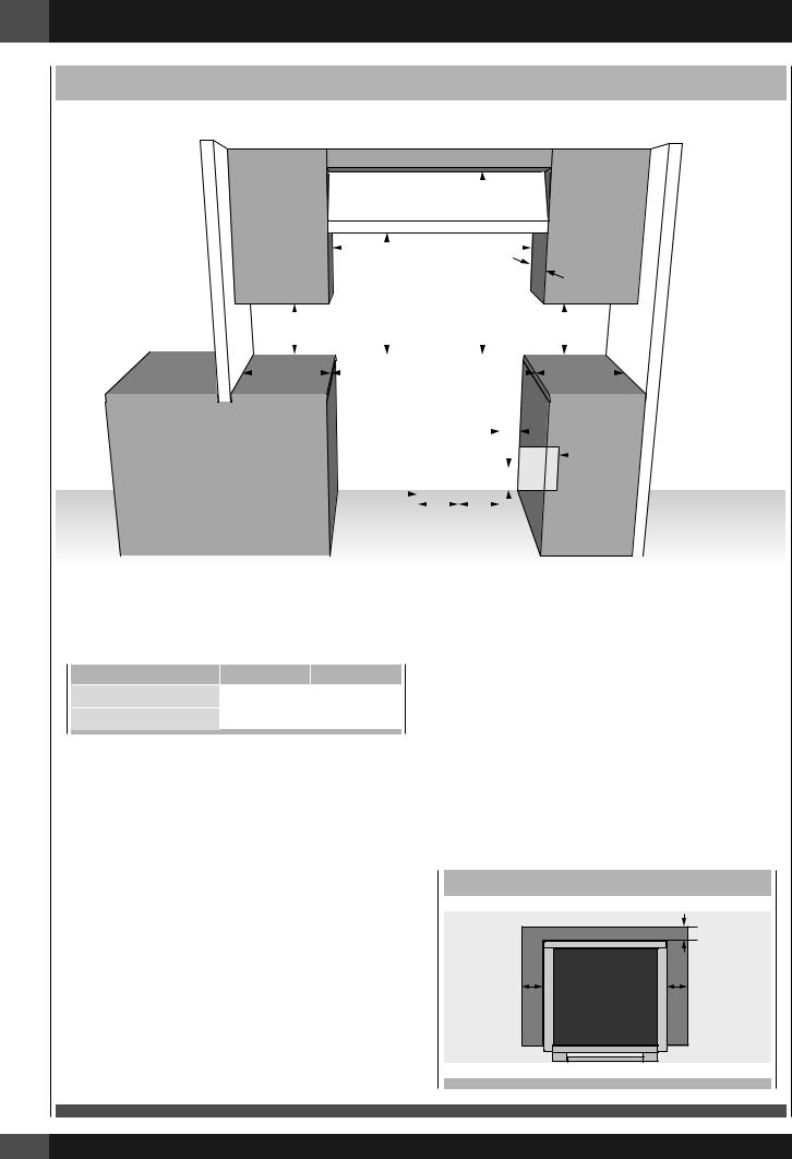
The surface of the entire back wall above the range and below the hood must be covered with a noncombustible material.
*Consult local code for exact location requirements.
OPENING WIDTH |
A & C |
|
B |
|
Range 30” |
30" |
(76.2) |
6” |
(15.2) |
Range 36” |
36" |
(91.4) |
7” |
(17.8) |
Note: Clearances from non-combustible materials are not part of the ANSI Z21.1 scope and not certied. Clearances to non-combustible materials must conform with local codes or, in the absence of local codes, with the National Fuel Gas Code, ANSI Z223.1/NFPA 54.
construction below the cooking surface and the back and sides of the appliance.
ADDITIONAL CLEARANCES:
For island installation, maintain 2-½ in. minimum from cutout to back edge of countertop and 3 in. minimum from cutout to side edges of countertop (see top view).
For installation in a stepped island, 12” (30.5 cm) minimum clearance is required from the back or sides of the rangetop to a combustible riser. The island installation is not part of the ANSI Z21.1 scope and not certified.
Minimum clearances:
Above cooking surface (above 36” [91.4 cm])
•Sides - 6” (15.2 cm)
•Within 6” (15.2 cm) side clearance, wall cabinets no deeper than 13” (33.0 cm) must be minimum 18” (45.7 cm) above cooking surface
•Wall cabinets directly above product must be a minimum of 48” (122 cm) above cooking surface.
•Rear - 0” with 9 ” backguard; 0” with non-combustible rear wall.
Below cooking surface (36” [91.4 cm] and below)
• Install with zero clearance between adjacent combustible
FLUSH ISLAND INSTALLATION
|
BACK |
|
min 2 1/2” (6.3) |
min 3” (7.6) |
min 3” (7.6) |
4
2 - Product Dimensions and Cutout Requirements EN
Before moving the range, protect any finished flooring and secure oven door(s) closed to prevent damage.
Vent hood Combinations:
It is recommended that these ranges be installed in conjunction with a suitable overhead vent hood.
Install a hood with at least 450 CFM.
Due to the high heat capacity of this unit, particular attention should be paid to the hood and ductwork installation to assure it meets local building codes.
WARNING
Air curtain or other overhead hoods, which operate by blowing a downward air flow on to a range, shall not be used in conjunction with ranges with gas cooktop other than when the hood and range have been designed, tested and certified by an independent test laboratory for use in combination with each other.
Clearances to horizontal surfaces above the range, measured to the cooking surface are below. Failure to comply may result in fire hazard.
•Installations without a hood require 48” (122) minimum to combustibles.
•A custom hood installation with exposed horizontal combustible surfaces must have an Auto-On feature.
•For other installations with a hood, refer to the hood installation instructions for specific hood clearances.
CAUTION
These ranges weigh up to 400 pounds. Some disassembly will reduce the weight considerably. Due to the weight and size of the range and to reduce the risk of personal injury or damage to the product:
TWO PEOPLE ARE REQUIRED FOR PROPER INSTALLATION.
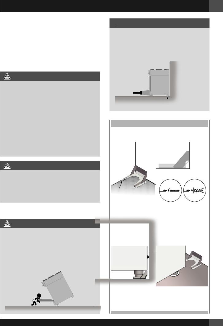
Anti-Tip Bracket Installation
WARNING
Tip Over Hazard
A child or adult can tip the range and be killed.
Ensure the anti-tip bracket is engaged when the range is moved.
Do not operate range without anti-tip bracket installed and engaged.
Failure to follow these instructions can result in death or serious burns to children and adults.
 WARNING
To verify the anti-tip bracket is installed and engaged:
•Slide range forward.
•Look for the anti-tip bracket securely attached to floor or wall.
•Slide range back so rear range foot is under anti-tip bracket.
•See installation instructions for details.
 Anti-Tip Bracket
 Range Foot
ANTI-TIP BRACKET INSTALLATION
BACKWALL |
WALL |
ANCHOR |
|
|
|
CABINET
SIDEWALL
ANTI-TIP
FLUSH BRACKET
For Concrete or Cement Construction:
You must use appropriate fastening hardware (not provided).
Secure the bracket to the wall and/or floor with at least 4 wood screws (provided).
The anti-tip bracket should be inserted into the opening on the anti-tip brace on the range.
5
EN 3 - Installation Information
WARNING
•Excessive Weight Hazard
Use two or more people to move and install range. Failure to do so can result in back or other injury.
•Cut Hazard
Beware of sharp edges. Use the polystyrene ends when carrying the product. Failure to use caution could result in minor injury or cuts.
Do not obstruct the flow of combustion air at the oven vent nor around the base or beneath the lower front panel of the range. Avoid touching the vent openings or nearby surfaces as they may become hot while the oven is in operation. This range requires fresh air for proper burner combustion.
NEVER cover any slots, holes or passages in the oven or cover an entire rack with aluminum foil. Doing so blocks air flow through the oven and may cause carbon monoxide poisoning. Aluminum foil linings may also trap heat, causing a fire hazard.
CHOOSING RANGE LOCATION
Carefully select the location where the range will be placed. The range should be located for convenient use in the kitchen, but away from strong drafts.
Strong drafts may be caused by open doors or windows, or by heating and/or air conditioning vents or fans.
IMPORTANT NOTE
When installing against a combustible surface, a minimum riser is required for a the range, Follow all minimum clearances to combustible surfaces shown in the illustration on the previous pages.
Before moving the range, protect any finished flooring and secure oven door(s) closed to prevent damage.
Do not lift or carry the range door by the door handle.
To eliminate the risk of burns or fire by reaching over heated surface units, cabinet storage space located above the surface units should be avoided. If cabinet storage is to be provided, the risk can be reduced by installing a range hood that projects horizontally a minimum of inches beyond the bottom of the cabinets.
All openings in the wall or floor where the range is to be installed must be sealed.
6
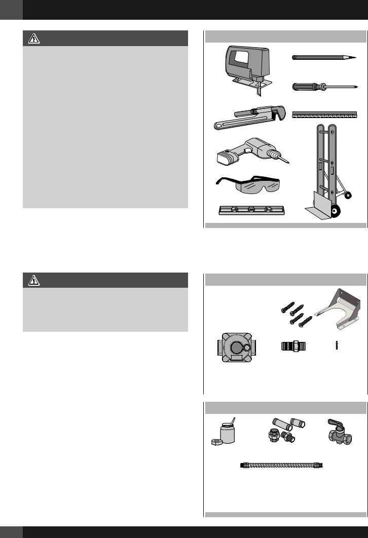
TOOLS WILL YOU NEED
Remove packaging materials and literature package from the cooktop before beginning installation.
Remove Installation Instructions from the literature pack and read them carefully before you begin
MATERIALS PROVIDED
Anti-tip bracket brace abd screws
Appliance |
Flare union |
Gasket |
pressure |
adaptor |
|
regulator |
|
|
|
|
|
|
|
|
MATERIALS REQUIRED (not provided)
Joint Sealant |
Pipe Fittings |
Shut-Off Valve |
5-foot maximum length, 5/8” O.D. CSA-approved flexible metal gas supply (3-foot maximum length in Massachusetts only)
NOTE: Purchase new flexible line; do not use previously used flexible gas line.
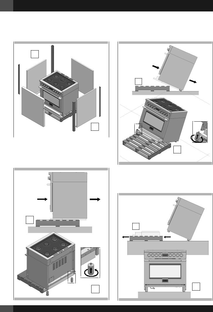
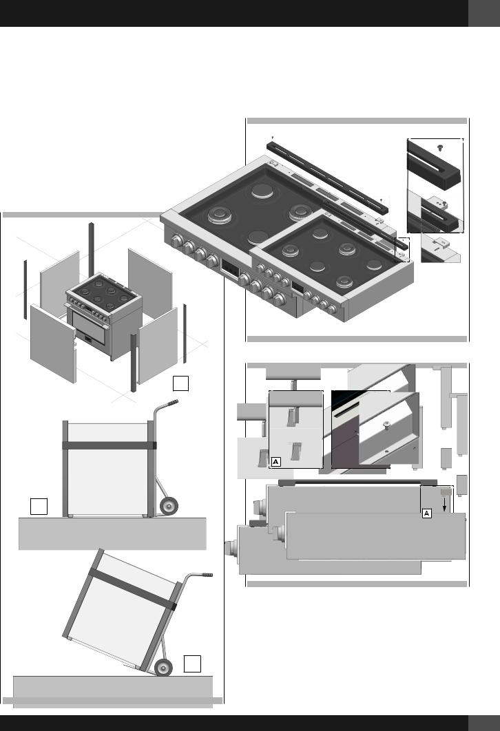
Do not tip the range on its side when installing the legs.The sidewalls are not designed to bear the weight of the range and will bend. Any damage as a result of tipping will not be covered by warranty. Follow the method in the enclosed installation Manual.
STEP 1
Cut the banding (1) and remove the Installation Instructions from the top of range and read them carefully before you begin.
CAUTION
Stand clear. The ends of the cut banding may snap toward you.
4 - Installation Instructions EN
STEP 2
Open the top (2) and remove the accessories (3) then lift off the cardboard sheath (4).
2
3
1
4
7
EN 4 - Installation Instructions
STEP 3
Remove Installation Instructions (5) from the top of range and read them carefully before you begin
STEP 5
Slide back more and tilt back (9), putting the rear legs on the floor and then mount the front legs (10) while in this angled position supported by the rear legs and the skid.
5
9
6
|
|
|
|
|
|
|
|
STEP 4 |
|
10 |
|
Slide the range back just enough to allow the rear feet to be installed.
STEP 6
Remove the base while supporting the front of the range (11) and lower to the floor in a controlled manner (12).
7
11
8 |
12 |
|
8
STEP 7
In case it is necessary to move the range; using the foam and/ or cardboard packaging (13), replace them around the range strategically to protect the finished surfaces of the range from contact with the hand-truck and any straps around the unit (14). In the case of smaller ranges, you may use this technique to remove the range from the skid and installing the legs (15). Tilt the range to lower the hand-truck wheels off the skid. Place appliance runners on the floor at the left and right sides in front of the opening when moving into final position to protect flooring. The oven door(s) add(s) a great deal to the overall weight of the range, you may find it helpful to remove the doors if moving the range a significant distance. Refer to the included instruction manuals for how to remove and reinstall the doors.
4 - Installation Instructions EN
STEP 8
Install the back guard (if provided) by the three screws on the back. In some cases this may be an accessory back guard that was ordered separately rather than the one which was included with the range. Refer to instructions included with any accessory for specific installation requirements.
13
9” 3”
14
15
9
EN 4 - Installation Instructions
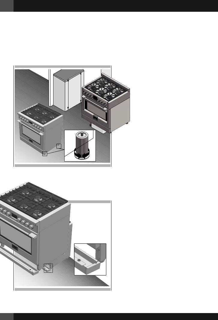
STEP 9
After completing the electrical and gas connections (see included instructions) measure the four corners in cutout area to verify if flooring is level. Adjust the leveling legs to the desired height and ensure range is level. Turn the bottom section of each leg counter-clockwise to raise the leg and clockwise to lower it.
Ensure floor is protected. Slide unit into place making sure to engage the anti-tip bracket.
STEP 10
Hook tabs on bottom of toekick into slots on either side of the frame and rotate up until the magnets at the top of toekick make contact and hold it in place securely
10
QUALIFIED SERVICE MAN OR GAS APPLIANCE INSTALLER MUST MAKE THE GAS SUPPLY CONNECTION.
Leak testing of the appliance shall be conducted by the installer according to the instructions given.
You must install the supplied connection parts seen here in this configuration to the main gas manifold on the appliance. Issues arising from a failure to do so will not be covered by warranty.
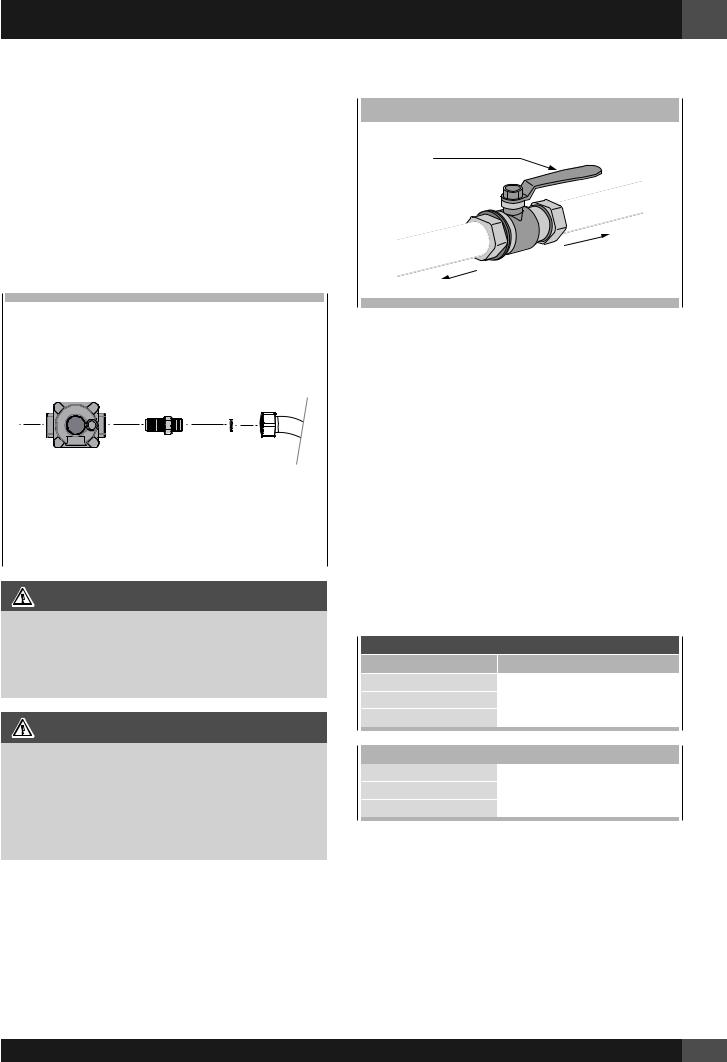
Do not install the pressure regulator backwards as the gas will not flow correctly. Check that the arrow on the back points in the direction of gas flow.
Parts required for connection from gas supply to regulator are the responsibility of the installer / owner
5 - Gas Requirement EN
GAS SHUT OFF VALVE
OPEN POSITION
|
|
|
|
|
|
|
|
|
LY |
|
|
|
|
|
|
|
|
P |
|
|
|
|
|
|
|
|
UP |
|
|
|
|
|
|
|
|
SS |
|
|
|
|
|
|
|
|
A |
|
|
|
|
|
|
|
|
|
G |
|
|
|
|
|
|
|
|
|
E |
|
|
|
|
|
|
|
|
C |
|
|
|
|
|
|
|
|
N |
|
|
|
|
|
|
|
|
LIA |
|
|
|
|
|
|
|
|
P |
|
|
|
|
|
|
|
|
TO |
AP |
|
|
|
|
|
|
|
|
|
|
|
|
|
|
|
|
|
|
Appliance
Appliance |
Flare union |
Gasket |
pressure regulator |
adaptor |
|
|
|
|
|
|
|
ATTENTION
Use Teflon tape rated for gas applications at all threaded connections.
Do not overtighten the connection at the manifold or you could damage the gasket causing a leak.
WARNING
If the line pressure supplying the appliance pressure regulator exceeds 14 inches W.C. (any gas), an external regulator must be installed in the gas line ahead of the appliance regulator to reduce the pressure to no more than 14 inches W.C. Failure to do this can result in malfunction and damage to the appliance.
Important Notes for Gas Connection
The appliance and its individual gas shutoff valve must be disconnected from the gas supply piping system during any pressure testing of that system at test pressures in excess of 1/2 psi (3.5 kPa).
The appliance must be isolated from the gas supply piping system by closing its individual manual shut-off valve during any pressure testing of the gas supply piping system at test pressures equal to or less than 1/2 psi (3.5 kPa).
All supply piping, except as noted, should use common National Pipe Thread (N.P.T.). For all pipe connections use an approved pipe joint compound resistant to the action of LP gas.
This appliance is designed for use with NG gas or LP gas. The gas pressure regulator is supplied with this appliance.
It must be installed in the gas ahead of the manifold entrance. It is pre-set for use with natural gas. To use it with different gas it must be converted, as described in the Gas Conversion paragraph.
If at any time the appliance is to be used with a different type of gas, all the conversion adjustments must be made by a qualified technician before attempting to operate the range with that gas.
The gas should be supplied to the appliance’s pressure regulator at line pressure between 6 and 14 inches of water column for
NG, and between 11 and 14 inches of water column for LP.
GAS REQUIREMENTS
NATURAL GAS |
WC |
|
|
|
Manifold Pressure |
5" |
(12.5 mb) |
||
Min Line Pressure |
6" |
(15 |
mb) |
|
Max Line Pressure |
14" |
(34.9 mb), .5 psi (3.5 kPa) |
||
LP GAS |
WC |
|
|
|
Manifold Pressure |
|
10” |
(25 |
mb) |
Min Line Pressure |
|
11” |
(27.4 mb) |
|
Max Line Pressure |
14” |
(34.9 mb), .5 psi (3.5 kPa) |
||
11
EN 5 - Gas Requirement
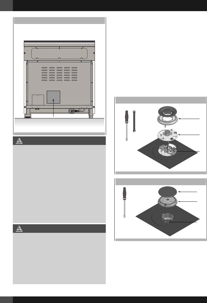
LOCATION OF GAS RATING PLATE
IMPORTANT
NEVER REUSE OLD CONNECTORS WHEN INSTALLING THIS RANGE.
To reduce the likelihood of gas leaks, apply teflon tape or a thread compound approved for use with LP or Natural gases to all threaded connections.
Apply a non-corrosive leak detection fluid to all joints and fittings in the gas connection between the supply line shut-off valve and the cooktop inlet.
Check for leaks!
Bubbles appearing around fittings and connections will indicate a leak. If a leak appears, turn off supply line gas shut-off valve, tighten connections, turn on the supply line gas shutoff valve, and retest for leaks. Never test for gas leaks with an open flame.
NEVER TIGHTEN TO MORE THAN 35 ft lbs OF TORQUE
CAUTION
Do not attempt to attach the flexible connector directly to an external pipe thread.
Connection requires flare union adapters. For Massachusetts Installations:
1.Shut-off valve must be a “T” handle gas valve.
2.Flexible gas connector must not be longer than 36 inch.
3.Not approved for installation in a bedroom or a bathroom unless unit is direct vent.
12
Pressure Testing
The appliance must be isolated from the gas supply piping system by closing its individual manual shut-off valve during any pressure testing of the gas supply piping system at test pressures equal to or less than 1/2 PSIG (3.5 kPa).
This appliance, as well as its individual shut-off valve, must be disconnected from the gas supply piping system during any pressure testing of the system at test pressures in excess of 1/2 PSIG (3.5 kPa).
When checking appliance regulator function, make certain pressure of natural gas supply is between 6 and 14 inches of water column or, if converted for LP gas, between 11 and 14 inches.
THE PRESSURE TESTING SHOULD BE PERFORMED BY MEANS OF THE INJECTOR THREAD ZONE
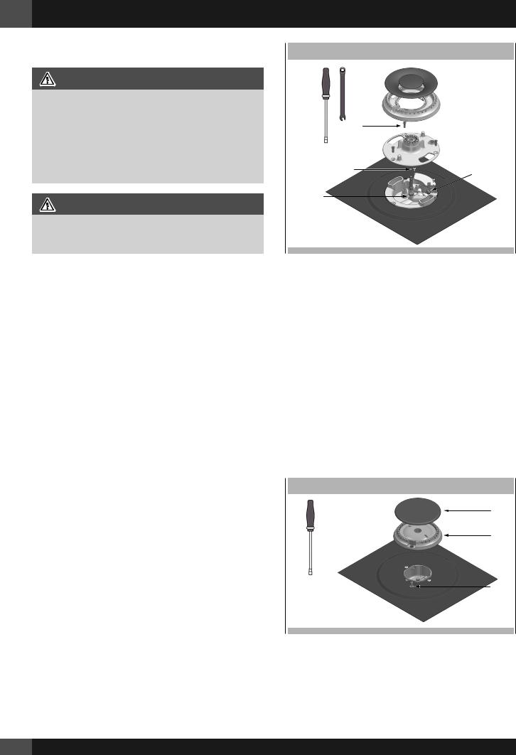
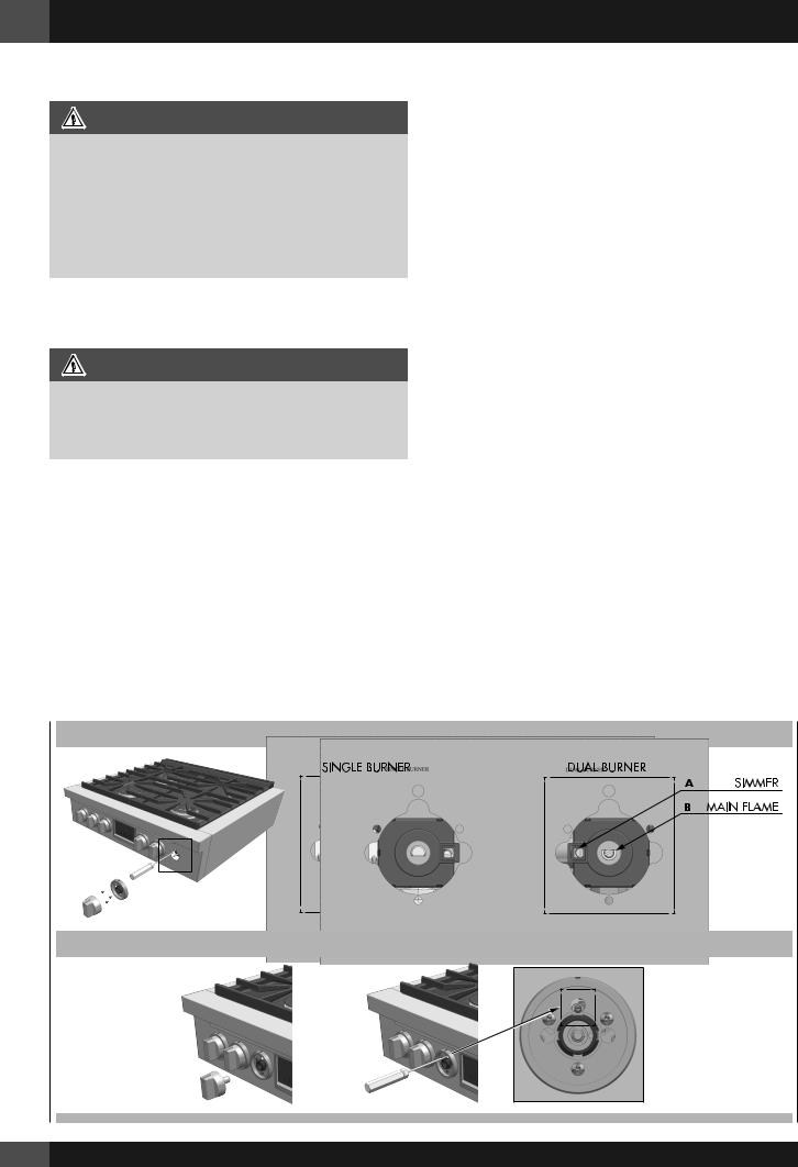
EXPLODED VIEW DUAL BURNER
1
2
A
EXPLODED VIEW SINGLE BURNER
1
2
A
Pressure Test Method
•Remove grate and burner cap (1).
•Remove aluminum gas spreader (2).
•Temporarily remove the injectors (A).
•Connect the pressure Test instrument into injector holder thread zone (M6x0,75).
•Check if the cooktop has the correct pressure.
•Fix the injector removed for testing and replace the parts in the right position.
5 - Gas Requirement EN
Gas Connection
•Thread the appliances pressure regulator with 1/2” male end connection both supplied with this appliance.
•Join the pressure regulator to the entrance threads of the Gas Manifold with gasket supplied with this appliance. The regulator is marked with a directional arrow indicating correct direction of gas flow. Ensure the appliance regulator is installed with the arrow pointing toward the gas manifold entrance.
•Connect a manual shut-off valve to the gas supply in an accessible location for turning on or shutting off gas to the appliance.
•Install a coupling between the regulator and the shutoff valve to complete the connection.
•Assure all pipe joint connections are gas tight.
•Check alignment of valves after connecting the cooktop to the gas supply to be sure the manifold pipe has not been moved.
FOR ALTERNATIVE PIPING METHODS TO CONNECT THE APPLIANCE TO THE GAS SUPPLY, A TRAINED SERVICE TECHNICIAN OR GAS APPLIANCE INSTALLER MUST MAKE THE GASSUPPLYCONNECTION.Leaktestingoftheapplianceshallbe conducted by the Installer according to the Instructions given.
Unless prohibited by local codes or ordinances, a new A.G.A. - Certified, flexible metal appliance connector may be used to connect this appliance to its gas supply.
The connector must have an internal diameter not less than nominal 1/2” NPT pipe and be no more than 5 feet in length. A 1/2” NPT x 1/2” flare union adapter is required at each end of the flexible connector.
If a flexible connector is used assure that both the appliance pressure regulator and manual shut-off valve are joined solidly to other permanent hard piping (either gas supply or the appliance manifold) so as to be physically stationary.
CAUTION
Do not attempt to attach the flexible connector directly to an external pipe thread.
Connection requires flare union adapters.
For Massachusetts Installations:
1.Shut-off valve must be a “T” handle gas valve.
2.Flexible gas connector must not be longer than 36 inches.
3.Not approved for installation in a bedroom or a bathroom unless unit is direct vent.
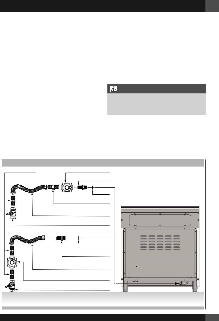
|
GAS CONNECTION |
FLARE UNION ADAPTOR |
APPLIANCE PRESSURE REGULATOR |
|
FLARE UNION ADAPTOR |
|
GASKET |
|
FLARE UNION ADAPTOR |
|
FLEXIBLE APPLIANCE CONNECTOR |
|
(5 FT.) MAX, (1.52 m) MAX |
|
MANIFOLD SHUTOFF VALVES |
GASKET
FLARE UNION ADAPTOR
FLEXIBLE APPLIANCE CONNECTOR (5 FT.) MAX, (1.52 m) MAX
APPLIANCE PRESSURE REGULATOR
MANIFOLD SHUTOFF VALVES
13
EN 6 - Conversion for LP or NG Gas
Converting Appliance for Use with LP Gas
WARNING
Conversion is to be performed by an AUTHORIZED SERVICER (or other qualified agency) in accordance with the manufacturer’s instructions and all codes and requirements of the authority having jurisdiction. Failure to follow instructions could result in serious injury or property damage.
The qualified agency performing this work assumes responsibility for this conversion.
CAUTION
Before proceeding with the conversion, shut off the gas supply to the appliance prior to disconnecting the electrical power
If this appliance is to converted for use with gas LP (propane or butane), each of the following modifications must be performed:
Gas conversion label (aluminium) to be placed on the back of the appliance, near the data plate, after conversion has been carried out;
Replace Injectors (two ring flame burner)
1.Remove the grates and burner caps.
2.Remove aluminium gas spreader.
3.Remove the three screws from the simmer gas spreader
(1).
4.Remove the two screws of the injector cover (2).
5.Remove injector (A) by using a 9-32” (7 mm) nut driver counter clockwise.
6.Remove injector (B) by using a 9-32” (7 mm) box wrench counter clockwise.
7.Install the injectors supplied with this appliance in the appropriate burner. The injectors have small numbers stamped on the side, this number corresponds with the orifice diameter and its correct burner location (refer to illustrations in the section: “Injectors Position”).
8.Turn clockwise to tighten (tighten to a torque of 15 to 20 inch-lbs).
9.Replace all parts following the reverse order.
10. Save the injectors removed from the appliances for future use.
14
EXPLODED VIEW DUAL BURNER
|
1 |
2 |
B |
|
A
Replace injector on (one ring flame or burners)
1.Remove the grates and burner cups.
2.Remove aluminum gas spreader.
3.Loosen injector by turning 9-32” (7 mm) nut driver counter clockwise.
4.Install the injectors supplied with this appliances in the appropriate burner. The injectors have small number stamped on the side, this number codes the orifice diameter and its correct burner location (see figure on page 18).
5.Turn clockwise to tighten (tighten to a torque of 15 to 20 inch-lbs).
6.Replace all parts following the reverse order.
7.Save the orifices removed from the appliance for future use.
EXPLODED VIEW SINGLE BURNER
1
2
A
6 - Conversion for LP or NG Gas EN
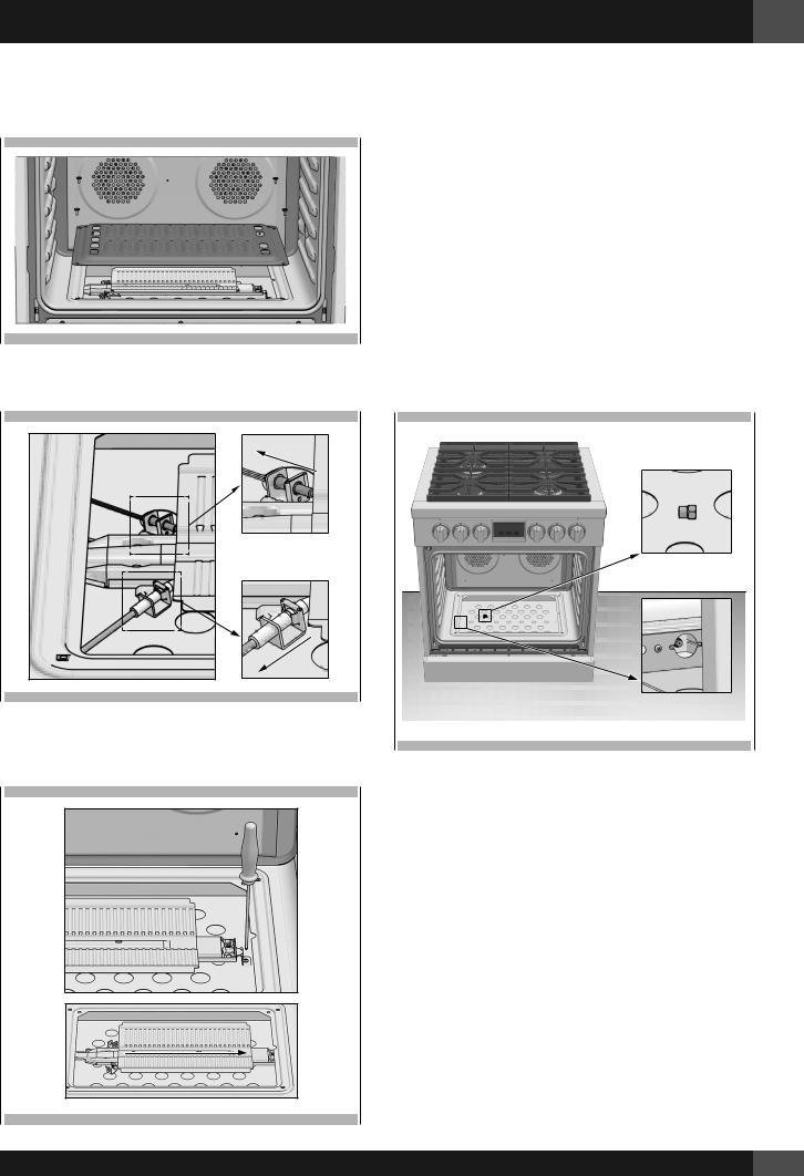
Replace injector on (oven lower burner)
1. Remove the burner cover plate.
2. Disconnect both heat sensor and the ignition spark plug.
4.Remove the nozzle by turning 9-32” (7 mm) nut driver counter clockwise.
5.Install the injectors supplied with this appliances in the appropriate burner. The injectors have small number stamped on the side, this number codes the orifice diameter and its correct burner location (see figure of the paragraph “Injectors position”).
6.Turn clockwise to tighten (tighten to a torque of 15 to 20 inch-lbs)
3.Remove the screw securing the oven burner and withdraw the burner from the support.
7. Replace all parts following the reverse order. Save the injectors removed from the appliances for future use.
15
EN 6 - Conversion for LP or NG Gas
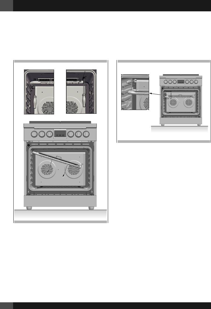
Replace injector on (oven grill burner)
1.Remove the door as described in the paragraph “Door removal”
2.Remove the screws securing the grill burner and withdraw the burner from the support.
3.Remove the nozzle by turning 9-32” (7 mm) nut driver counter clockwise.
4.Install the injectors supplied with this appliances in the appropriate burner. The injectors have small number stamped on the side, this number codes the orifice diameter and its correct burner location (see figure of the paragraph “Injectors position”).
5.Turn clockwise to tighten (tighten to a torque of 15 to 20 inch-lbs)
6.Replace all parts following the reverse order paying attention to the correct placement of the burner.
7.Save the injectors removed from the appliances for future use.
16
Proceed to Pressure Regulator Conversion noting the LP / Propane position to complete the conversion.
After replacing the injectors adjust the burner flame (see Low Flame Adjustment paragraph).
Check the appearance of each burner’s flame at HILO settings, if the flame appears too large or too small make sure that all steps were completed correctly.
Converting Appliances for Use with NG Gas
If this appliance should be converted for use with gas NG (natural gas), each of the following modifications must be performed.
1.Convert the pressure regulator to NG position as per the section “Pressure Regulator Conversion”.
2.Replace all injectors following the step described on the previous pages, observe the number stamped on the side, this number corresponds to the orifice diameter and its correct burner location (refer to the illustrations in section: “Injectors Position”).
3.Adjust the burner flame (see Low Flame Adjustment section).
Check the appearance of each burner’s flame at HI - LO settings, if the flame appears too large or too small make sure that all steps were completed correctly.
Pressure regulator conversion
The appliances is designed for use with NG gas or LP gas. The gas pressure regulator is supplied. It must be installed in the gas supply line ahead of the manifold entrance.
It is pre-set for use with the gas as indicated on the appliance label supplied with the appliance. For use with different gas the appliance must be converted.
For the pressure regulator conversion follow the instructions below:
•Disconnect all electrical power, at the main circuit breaker or fuse box.
•Shut off the gas supply to the cooktop by closing the manual shut-off valve.
•Adjust the pressure regulator, by following the instruction (see figure)
1.Unscrew the regulator cap
2.Unscrew the plastic conversion plug from the cap turn over and screw back (wide section away from cap for LP and against cap for NG) see figures below.
3.Replace the regulator cap ensuring gasket is in place.
6 - Conversion for LP or NG Gas EN
PRESSURE REGULATOR CONVERSION

 CAP
CAP
GASKET
NG POSITION

 LP/PROPANE POSITION
 PRESSURE REGULATOR
PLUG
NG |
LP |
Before replacing the regulator cap, check if the position of plug is suitable for the gas
17
EN 6 - Conversion for LP or NG Gas
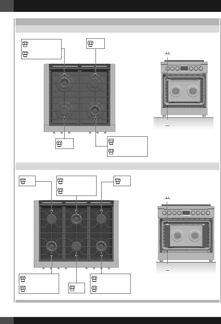
INJECTORS POSITION
NGDUAL FLAME RING 30”
SIMMER |
72 |
180 |
MAIN FLAME 180 |
|
|
|
180 |
|
SIMMER |
72 |
|
|
|
|
|
|
|
|
MAIN FLAME 180 |
|
|
|
NGDUAL FLAME RING 36” |
|
|
180 |
SIMMER |
72 |
180 |
|
|
MAIN FLAME 180 |
|
|
|
SIMMER |
72 |
|
SIMMER |
72 |
MAIN FLAME 180 |
180 |
MAIN FLAME 180 |
||
* depending on the model
18
 175
175
 210
210
 200
200
 230
230
6 - Conversion for LP or NG Gas EN
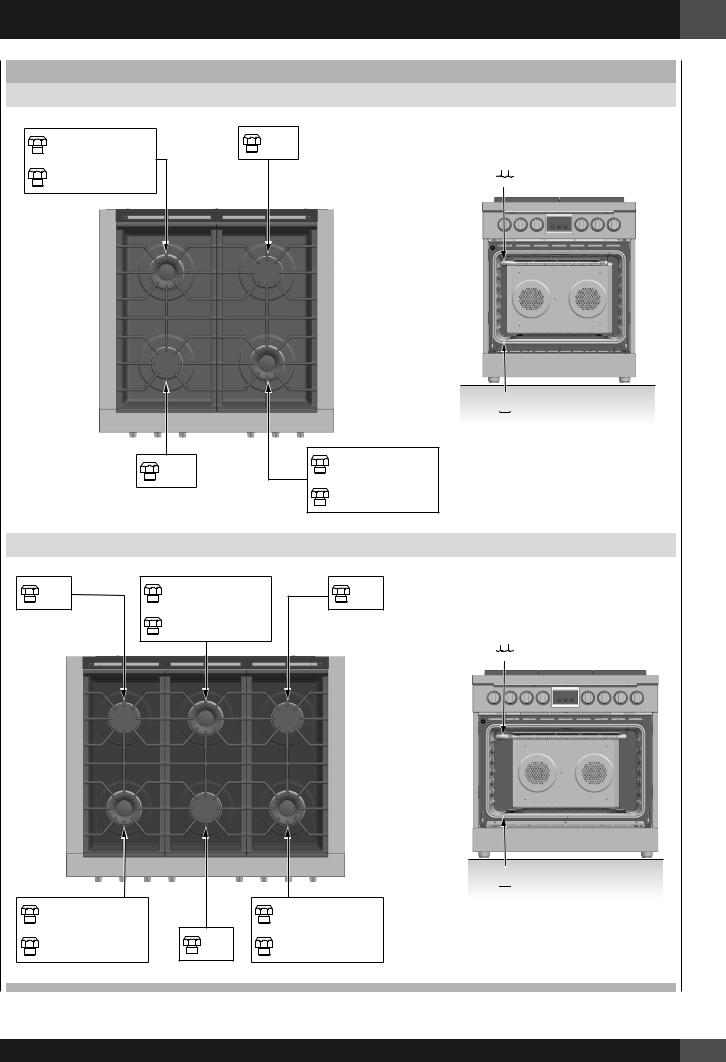
INJECTORS POSITION
LPDUAL FLAME RING 30”
SIMMER |
50 |
105 |
MAIN FLAME 105 |
|
|
|
105 |
|
SIMMER |
50 |
|
|
|
|
|
|
|
|
MAIN FLAME 105 |
|
|
|
|
LPDUAL FLAME RING 36” |
|
105 |
SIMMER |
50 |
105 |
|
|
MAIN FLAME 105 |
|
|
|
 110
110
 125
125
 120
120
 140
140
SIMMER |
50 |
|
SIMMER |
50 |
MAIN FLAME 105 |
105 |
MAIN FLAME 105 |
||
19
EN 6 - Conversion for LP or NG Gas
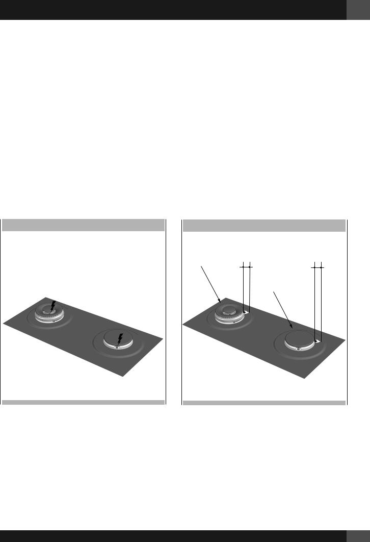
Low Flame Adjustment
DANGER
Lighting gas burners with a match is dangerous.
You should match light the burners only in an emergency.
Light a match and hold the flame near the burner you want to light. Wooden matches work best.
Push in and turn the control knob slowly.
Be sure you are turning the correct knob for the burner you are lighting.
NOTE: If the burner does not light within five seconds, turn the knob off and wait one minute before trying again.
CAUTION
If you attempt to measure the inner cone of the flame, please use caution.
Burns could result.
This appliance is shipped from the factory with low and medium flame settings adjusted.
If further adjustment is necessary, proceed as follows:
Adjustment for Burners with one or two flame rings:
1.Light burner and set control knob for low flame.
2.Remove control knob from valve stem.
3.Remove knob seat from control panel.
4.Insert a slender, thin-blade screwdriver into the recess behind the control knob (A or B) and engage blade with slot in adjusting screw.
5.Turn adjusting screw to set flame size:
•clockwise to reduce
•counterclockwise to increase
6.Replace control knob when adjustment is completed.
Adjustment for Lower Oven Burner:
1.Light burner and set control knob for low flame.
2.Remove control knob from valve stem.
Conversion from natural gas to liquid gas
3.insert the screwdriver in the hole in the front wall of the instrument panel and turn regulation screw A clockwise.
Conversion from liquid gas to natural gas
4.Light the oven with thermostat set to 250 °C for at least 1015 minutes.
Then, turn the thermostat to the minimum position and turn the bypass screw A counterclockwise until you see a reduced by stable flame.
NOTE: Check that the flame does not go out when the door of the oven is opened and closed repeatedly. If the flame goes out, slight increase the minimum regulation setting.
5. Replace control knob when adjustment is completed.
ADJUSTMENT FOR COOKTTOP BURNERS
ADJUSTMENT FOR LOWER OVEN BURNER
20
6 - Conversion for LP or NG Gas EN
Proper adjustment will produce a stable, steady blue flame of minimum size.
The final adjustment should be checked by turning the knob from high to low several times without extinguishing the flame. This adjustment, at low setting, will automatically provide the proper flame size at medium setting.
After Conversion steps have been completed, check the appearance of each burner’s flame at the HI and LO settings, if the flames appear too large or too small
review each step to make sure it was completed correctly.
NOTE: To obtain the correct minimum setting with LP gas, turn clockwise tightening the valve(s) fully with the thin-blade screwdriver into the recess behind control knob (A and / or B).
Electric Gas Ignition
The gas burners use an electric ignition device located near each burner ensures burners ignite automatically.
ELECTRIC IGNITION
See Use & Care manual for better explanation and its control.
The Burner Flames
Turn each burner on. Flames should be blue in color with no trace of yellow. The burner flames should not flutter or blow away from the burner The inner cone of the flame should be between 1/2” and 3/4” long.
BURNER FLAMES
BURNER |
1/2” to 3/4” |
1/2” to 3/4” |
|
|
|
|
BURNER |
|
21
 Loading...