


PLANO
CPH 604 G TC CPH 765 GWK TC CPH 905 GWK TC CPH 1124 GWK TC

Caro Cliente,
sentitamente La ringraziamo e ci congratuliamo per la scelta da Lei fatta. Questo nuovo prodotto, accuratamente progettato e costruito con materiali di primissima qualità, è stato accuratamente collaudato per poter soddisfare tutte le Sue esigenze di una perfetta cottura. La preghiamo pertanto di leggere e rispettare le facili istruzioni che Le permetteranno di raggiungere eccellenti risultati sin dalla prima utilizzazione. Con questo moderno apparecchio Le formuliamo i nostri più vivi auguri.
IL COSTRUTTORE
Indice
Istruzioni per l’utente
Installazione, 4
Uso, 4
Manutenzione, 7
Istruzioni per l’installatore
Installazione, 8
Collegamento gas, 11
Collegamento elettrico, 11
Caratteristiche utilizzatori, 14
QUESTO PRODOTTO È STATO CONCEPITO PER UN IMPIEGO DI TIPO DOMESTICO. IL COSTRUTTORE DECLINA OGNI RESPONSABILITÀ NEL CASO DI EVENTUALI DANNI A COSE O PERSONE DERIVANTI DA UNA NON CORRETTA INSTALLAZIONE O DA USO IMPROPRIO, ERRONEO OD ASSURDO. L’APPARECCHIO NON DEVE ESSERE USATO DA PERSONE (COMPRESI BAMBINI) CON RIDOTTE CAPACITÀ FISICHE,
I |
Italiano |
I |
|
|
|
GB English
FR Français
DE Deutsch
ES Español
PT Português
SENSORIALI O MENTALI, O DA PERSONE CHE MANCANO DELL’ESPERIENZA E DELLE CONOSCENZE NECESSARIE SE NON SOTTO LA SUPERVISIONE O DIETRO ISTRUZIONI SULL’USO DELL’APPARECCHIO DA PARTE DI UNA PERSONA RESPONSABILE PER LA LORO SICUREZZA. I BAMBINI DEVONO ESSERE CONTROLLATI PER ASSICURARSI CHE NON GIOCHINO CON L’APPARECCHIO.
3

Istruzioni per l’utente
I Installazione
Tutte le operazioni relative all’installazione (allacciamento elettrico, allacciamento gas, adattamento al tipo di gas, conseguenti regolazioni, ecc.) devono essere eseguite da personale qualificato secondo le norme vigenti. Per le istruzioni specifiche vedi la parte
riservata all’installatore.
Spegnimento di un bruciatore
Per ottenere lo spegnimento di un bruciatore è necessario premere contemporaneamente i rispettivi tasti + e - per un breve istante.
Spegnimento di tutti i bruciatori
Per ottenere lo spegnimento simultaneo di tutti i bruciatori è sufficiente premere brevemente il tasto ON/OFF, in questo modo il dispositivo si porterà in condizione di standby.
Uso
Modalità standby (Fig. 1-2-3)
Dopo avere alimentato il dispositivo, verrà eseguita una breve autodiagnosi e una calibrazione della tastiera a sfioramento (tutti i display e led rimangono accesi per alcuni secondi). Al termine il display sarà completamente spento. In questa modalità sarà possibile accendere il dispositivo soltanto con la pressione del tasto ON/OFF.
Accensione del Piano Cottura
Per accendere il dispositivo è necessario premere in modo continuo il tasto ON/OFF per almeno 2 secondi. Il dispositivo si accenderà e i display relativi ai bruciatori visualizzeranno il livello zero che corrisponde allo stato di bruciatori spenti.
Accensione di un bruciatore
Per accendere un bruciatore premere i relativi tasti + e - sul pannello comandi. La pressione dei tasti deve avvenire in modo simultaneo e continuo per almeno 1 secondo. All’accensione del bruciatore il livello di portata del bruciatore verrà impostato alla portata media e il relativo display indicherà il livello 3.
Ogni bruciatore per il quale non è programmato il relativo temporizzatore, si spegne automaticamente dopo 4 ore di funzionamento continuo.
L’accensione del bruciatore è segnalata anche dal relativo led vicino al display timer che rimarrà attivo per tutto il periodo in cui il bruciatore resterà acceso.
Regolazione del livello fiamma di un bruciatore
A bruciatore acceso, per aumentare il livello di portata è necessario premere il tasto +, viceversa per diminuire il livello di portata, è necessario premere il tasto -. Per ottenere una variazione continua del livello di portata, è sufficiente mantenere premuto il tasto + o - e rilasciarlo al livello desiderato. Il livello di portata può variare da 1 a 5.
Programmazione del tempo di spegnimento di un bruciatore
Con il dispositivo è possibile impostare in modo indipendente per ciascuno dei bruciatori, un tempo oltre il quale il bruciatore si spegne automaticamente.
Per impostare la programmazione del timer di un bruciatore occorre premere il tasto PT. Nella parte del pannello comandi, dove è rappresentata la posizione di ogni bruciatore con un led, l’indicatore del bruciatore A (Led-A) si accenderà, per segnalare che il bruciatore A e’ attualmente selezionato per la programmazione. Con i tasti P+ e P- e’ possibile eseguire la selezione del bruciatore da temporizzare. Il bruciatore selezionato è individuato dall’accensione del relativo indicatore in modo lampeggiante. Il display timer riporterà l’indicazione 0.00 per segnalare che il timer relativo al bruciatore selezionato non e’ attivo. Per impostare la programmazione del tempo di spegnimento del bruciatore selezionato, premere nuovamente il tasto PT; il display del timer indicherà 0.00. La cifra lampeggiante a sinistra del punto indica le ore, quelle a destra i minuti. Premendo i tasti P+ o P- e’ possibile incrementare o decrementare il numero di ore di funzionamento da 0 a 9. Mantenendo premuti i tasti P+ o P- la variazione del numero di ore avviene in modo continuo.
Per specificare il numero dei minuti, premere nuovamente il tasto PT. Si attiva il lampeggio delle cifre a destra del punto separatore. Per impostare i minuti agire come indicato per le ore.
Durante la programmazione del tempo e’ possibile in ogni momento, azzerare l’impostazione corrente premendo insieme i tasti P+ e P-. Un tempo uguale a zero disattiva il temporizzatore del bruciatore. Per confermare il tempo visualizzato sul display occorre premere il tasto PT. A questo punto rimangono accesi in modo lampeggiante solo i segnalatori dei bruciatori che hanno il temporizzatore attivo.
Premendo il tasto PT e’ possibile rientrare nella modalità di programmazione dei timer per visualizzare il tempo rimanente allo spegnimento o per modificare le impostazioni correnti. Se durante la programmazione non viene premuto nessun tasto per un periodo superiore a 10 secondi, la procedura di impostazione viene interrotta in modo automatico e ritornerà la
4

visualizzazione principale. Eventuali impostazioni in corso di modifica sul bruciatore selezionato non sono perse e il relativo timer risulterà attivo.
Il timer può essere programmato sia a bruciatore spento che a bruciatore acceso, ed il conteggio partirà immediatamente dopo la conferma del tempo impostato. Allo scadere del conteggio il bruciatore temporizzato verrà spento e contemporaneamente verrà emessa una sequenza di impulsi sonori per una durata di 30 secondi. Questa sequenza può essere interrotta selezionando il tasto PT.
Lo spegnimento di un bruciatore da parte dell’utente determina la disattivazione del relativo timer.
Regolazione dell’orologio
In seguito ad interruzioni di alimentazione sarà necessario impostare l’ora visualizzata dall’orologio interno al dispositivo.
Per regolare l’orologio è necessario premere contemporaneamente i tasti PT, P- e P+ per almeno 3 secondi.
La cifra lampeggiante a sinistra del punto indica le ore, quelle a destra i minuti. Premendo i tasti P+ o P- e’ possibile incrementare o decrementare le ore, e mantenendo premuti i tasti P+ o P- la variazione del numero di ore avviene in modo continuo.
Per regolare i minuti premere nuovamente il tasto PT. Si attiverà il lampeggio delle cifre a destra del punto separatore e poi per variare i minuti agire come indicato per le ore.
Premendo il tasto PT verrà poi memorizzato l’orario impostato.
Sblocco bruciatore
I bruciatori in stato di blocco hanno il relativo display che visualizza il carattere “b”. Lo sblocco si attiva premendo insieme i tasti - del bruciatore A e il tasto KL in modo continuo per almeno 2 sec. Al termine dello sblocco i bruciatori verranno ripristinati al livello 0, pronti per essere accesi nuovamente.
N.B: Se si dovesse ripetere la procedura di sblocco per 5 volte consecutive in un periodo di 15 minuti, il dispositivo visualizzerà FT06 e non accetterà alcuna richiesta di sblocco per ulteriori 15 minuti.
Blocco della tastiera
Si attiva premendo il solo tasto KL per almeno 2 secondi. Tutti i livelli dei bruciatori rimarranno al livello attuale. Lo stato di tastiera bloccata si manifesta con l'accensione dei punti decimali nei display del livello di portata relativi ad ogni bruciatore. Durante il blocco della tastiera non è più possibile variare i livelli dei bruciatori o cambiare le impostazioni del timer, ma è possibile in ogni caso spegnere il piano premendo il tasto ON/OFF.
Non è possibile sbloccare un bruciatore in blocco, |
I |
||||||||
mentre il blocco della tastiera è attivo. Sarà pertanto |
|||||||||
necessario sbloccare la tastiera prima di eseguire la |
|
||||||||
|
|||||||||
procedura di sblocco bruciatori. |
|
|
|
|
|
|
|||
Sblocco della tastiera |
|
|
|
|
|
|
|
||
La tastiera si sblocca premendo il tasto KL e il tasto + del |
|
||||||||
bruciatore A per almeno 2 sec. Lo sblocco della tastiera |
|
||||||||
si manifesta con lo spegnimento dei punti nei display del |
|
||||||||
livello fiamma. |
|
|
|
|
|
|
|
|
|
Calore Residuo |
|
|
|
|
|
|
|
|
|
Quando si spegne un fuoco, sul relativo display compare |
|
||||||||
una "H" per segnalare su quel bruciatore la presenza |
|
||||||||
di una temperatura ancora elevata, anche il relativo led |
|
||||||||
vicino al display del timer, rimane acceso. |
|
|
|
|
|||||
Il simbolo "H" e il led si spengono successivamente |
|
||||||||
quando la temperatura del relativo bruciatore si è ridotta. |
|
||||||||
Cotture speciali lente (Duty Cycle) |
|
|
|
|
|||||
Questa funzione permette di accendere e spegnere |
|
||||||||
un bruciatore qualsiasi del piano cottura secondo la |
|
||||||||
sequenza riportata in tabella. |
|
|
|
|
|
|
|
||
|
|
|
|
|
|
|
|
|
|
LIVELLO |
1 |
|
2 |
3 |
|
4 |
5 |
|
|
IMPOSTATO |
|
|
|
|
|||||
|
|
|
|
|
|
|
|
|
|
|
|
|
|
|
|
|
|
|
|
TEMPO DI |
10 |
|
20 |
30 |
|
40 |
50 |
|
|
SPEGNIMENTO |
Sec. |
Sec. |
Sec. |
Sec. |
Sec. |
|
|
||
|
|
|
|
|
|
|
|
|
|
TEMPO DI |
50 |
|
40 |
30 |
|
20 |
10 |
|
|
ACCENSIONE |
Sec. |
Sec. |
Sec. |
Sec. |
Sec. |
|
|
||
|
|
|
|
|
|
|
|
|
|
La funzione si attiva premendo contemporaneamente il tasto + del fuoco su cui si vuole applicare, ed il tasto PT (il bruciatore interessato deve essere spento nel momento in cui si attiva la funzione).
Il bruciatore si accende a livello 3 ed in quel momento si può impostare, agendo sui tasti + e -, il livello a cui applicare la funzione.
Se ad esempio si imposta il valore a livello 1, il bruciatore rimarrà acceso per 50 secondi, poi si spegnerà per 10 secondi e poi ripeterà questo ciclo fintanto che l'utente non spegnerà il brucitore.
Se l'utente non interviene, dopo 60 minuti si spegne automaticamente. Quando è attiva questa funzione, il display del fuoco su cui è attiva, lampeggia.
5

Mod: CPH 604 G TC
I
L'accensione di un led indica l'attivazione del fuoco corrispondente. Un led lampeggiante indica l'attivazione del timer su fuoco corrispondente.
|
|
|
|
|
|
|
|
|
|
|
|
|
|
|
|
|
|
|
|
|
|
|
|
|
|
|
|
|
|
|
|
|
|
|
|
|
|
|
|
|
|
|
|
Regolazine |
Regolazine |
Regolazine |
Regolazine |
Regolazine |
|
Accensione/ |
|||||||||||||||
Fuoco A |
Fuoco B |
Fuoco C |
Fuoco D |
|
Timer |
|
|||||||||||||||
|
|
spegnimento |
|||||||||||||||||||
Fig. 1 |
|
|
|
|
|
|
|
|
Attivazione timer |
|
|
|
Blocco |
|
|||||||
|
|
|
|
|
|
|
|
|
|
|
|
|
|||||||||
|
|
|
|
|
|
|
|
|
|
|
|
|
|
|
|
|
|
|
|
|
|
Mod: CPH 765 GWK TC
CPH 905 GWK TC
L'accensione di un led indica l'attivazione del fuoco corrispondente.
Un led lampeggiante indica l'attivazione del timer su fuoco corrispondente.
|
|
|
|
|
|
|
|
|
|
|
|
|
|
|
|
|
|
|
|
|
|
|
|
|
|
|
|
|
|
|
|
|
|
|
|
|
|
|
|
|
|
|
|
|
|
|
|
|
|
|
|
|
|
|
|
|
|
|
|
|
|
|
|
|
|
|
|
|
|
|
|
|
|
|
|
|
|
|
|
|
|
|
|
|
|
|
|
|
|
|
|
|
|
|
|
|
|
|
|
|
|
|
|
|
|
|
|
|
|
|
|
|
|
|
|
|
|
|
|
|
|
|
|
|
|
|
|
|
|
|
|
|
|
|
|
|
|
|
|
|
|
|
|
|
|
|
|
|
|
|
|
|
|
|
|
|
|
|
|
|
|
|
|
|
|
|
|
|
|
|
|
|
|
|
|
|
|
|
|
|
|
|
|
|
|
|
|
|
|
|
|
|
|
|
|
|
|
|
|
|
|
|
|
|
|
|
|
|
|
|
|
|
|
|
|
|
|
|
|
|
|
|
|
|
|
|
|
|
|
|
|
|
|
|
|
|
|
|
|
|
|
|
|
|
|
|
|
|
|
|
|
|
|
|
|
|
|
|
|
|
|
|
|
|
|
|
|
|
|
|
|
|
|
|
|
|
|
|
|
|
|
|
|
|
|
|
|
|
|
|
|
|
|
|
|
|
|
|
|
|
|
|
|
|
|
|
|
|
|
|
|
|
|
|
|
|
|
|
|
|
|
|
|
|
|
|
|
|
|
|
|
|
|
|
|
|
|
|
|
|
|
|
|
|
|
|
|
|
|
|
|
|
|
|
|
|
|
|
|
|
|
|
|
|
|
|
|
|
|
|
|
|
|
|
|
|
|
|
|
|
|
|
|
|
|
|
|
|
|
|
|
|
|
|
|
|
|
|
|
|
|
|
|
|
|
|
|
|
|
|
|
|
|
|
|
|
|
|
|
|
|
|
|
|
|
|
|
|
|
|
|
|
|
|
|
|
|
|
|
|
|
|
|
|
|
|
|
|
|
|
|
|
|
|
|
|
|
|
|
|
|
|
|
|
|
|
|
|
|
|
|
|
|
|
|
|
|
|
|
|
|
|
|
|
|
|
|
|
|
|
|
|
|
|
|
|
|
|
|
|
|
|
|
|
|
|
|
|
|
|
|
|
|
|
|
|
|
|
|
|
|
|
|
|
|
|
|
|
|
|
|
|
|
|
|
|
|
|
|
|
|
|
|
|
|
|
|
|
|
|
|
|
|
|
|
|
|
|
|
|
|
|
|
|
|
|
|
|
|
|
|
|
|
|
|
|
|
|
|
|
|
|
|
|
|
|
|
|
|
|
|
|
|
|
|
|
|
|
|
|
|
|
|
|
|
|
|
|
|
|
|
|
|
|
|
|
|
|
|
|
|
|
|
|
|
|
|
|
|
|
|
|
|
|
|
|
|
|
|
|
|
|
|
|
|
|
|
|
|
|
|
|
|
|
|
|
|
|
|
|
|
|
|
|
|
|
|
|
|
|
|
|
|
|
|
|
|
|
|
|
|
|
|
|
|
|
|
|
|
|
|
|
|
|
|
|
|
|
|
|
|
|
|
|
|
|
|
|
|
|
|
|
|
|
|
|
|
|
|
|
|
|
|
|
|
|
|
|
|
|
|
|
|
|
|
|
|
|
|
|
|
|
|
|
|
|
|
|
|
|
|
|
|
|
|
|
|
|
|
|
|
|
|
|
|
|
|
|
|
|
|
|
|
|
|
|
|
|
|
|
|
|
|
|
|
|
|
|
|
|
|
|
|
|
|
|
|
|
|
|
|
|
|
|
|
|
|
|
|
|
|
|
|
|
|
|
|
|
|
|
|
|
|
|
|
|
|
|
|
|
|
|
|
|
|
|
|
|
|
|
|
|
|
|
|
|
|
|
|
|
|
|
|
|
|
|
|
|
|
|
|
|
|
|
|
|
|
|
|
|
|
|
|
|
|
|
|
|
|
|
|
|
|
|
|
|
|
|
|
|
|
|
|
|
|
|
|
|
|
|
|
|
|
|
|
|
|
|
|
|
|
|
|
|
|
|
|
|
|
|
|
|
|
|
|
|
|
|
|
|
|
|
|
|
|
|
|
|
|
|
|
|
|
|
|
|
|
|
|
|
|||||||||||||||||||||||||||||||||
|
|
|
|
|
|
Regolazine |
Regolazine |
Regolazine |
Regolazine |
|
Regolazine |
|
|
|
|
|
|
|
|
|
|
|
|
|
Regolazine |
|
|
|
|
|
|
|
||||||||||||||||||||||||||||||||||||||||||||||||||||||||||||||||||||||||||||||||||||||||||
|
|
|
|
|
|
|
Fuoco A |
|
Fuoco B |
|
Fuoco C |
Fuoco D |
|
|
Fuoco E |
|
|
|
|
|
|
|
|
|
|
|
|
|
|
|
Timer |
|
|
|
|
|
|
|
||||||||||||||||||||||||||||||||||||||||||||||||||||||||||||||||||||||||||||||||||||
|
|
|
|
|
|
|
|
|
|
|
|
|
|
|
|
|
|
|
|
|
|
|
|
|
|
|
|
|
|
|
|
|
|
|
|
|
|
|
|
|
|
|
|
|
|
|
|
|
|
|
|
|
|
|
|
|
|
|
|
|
|
|
|
|
|
|
|
|
|
|
|
|
|
|
|
|
|
|
|
|
|
|
|
|
|
|
|
|
|
|
|
|
|
|
|
|
|
|
|
|
Blocco |
|
|
Accensione/ |
|
|
||||||||||||||||
|
|
|
|
|
|
|
|
|
|
|
|
|
|
|
|
|
|
|
|
|
|
|
|
|
|
|
|
|
|
|
|
|
|
|
|
|
|
|
|
|
|
|
|
|
|
|
|
|
|
|
|
|
|
|
|
|
|
|
|
|
|
|
|
|
|
Attivazione timer |
|
|
|
|
|
|
|
|
|
|
|
|
|
|
|
|
|
|
|
|
|
|
|
|
|
|
|
|
|
|
|
|
|
|
|
|
|
|
||||||||||||||||||
|
Fig. 2 |
|
|
|
|
|
|
|
|
|
|
|
|
|
|
|
|
|
|
|
|
|
|
|
|
|
|
|
|
|
|
|
|
|
|
|
|
|
|
|
|
|
|
|
|
|
|
|
|
|
|
|
|
|
|
|
|
|
|
|
|
|
|
|
|
|
|
|
|
|
|
spegnimento |
|
|
||||||||||||||||||||||||||||||||||||||||||||||||
|
|
|
|
|
|
|
|
|
|
|
|
|
|
|
|
|
|
|
|
|
|
|
|
|
|
|
|
|
|
|
|
|
|
|
|
|
|
|
|
|
|
|
|
|
|
|
|
|
|
|
|
|
|
|
|
|
|
|
|
|
|
|
|
|
|
|
|
|
|
|
|
|
|
|
|
|
|
|
|
|
|
|
|
|
|
|
|
|
|
|
|
|
|
|
|
|
|
|
|
|
|
|
||||||||||||||||||||
|
|
|
|
|
|
|
|
|
|
|
|
|
|
|
|
|
|
|
|
|
|
|
|
|
|
|
|
|
|
|
|
|
|
|
|
|
|
|
|
|
|
|
|
|
|
|
|
|
|
|
|
|
|
|
|
|
|
|
|
|
|
|
|
|
|
|
|
|
|
|
|
|
|
|
|
|
|
|
|
|
|
|
|
|
|
|
|
|
|
|
|
|
|
|
|
|
|
|
|
|
|
|
|
|
|
|
|
|
|
|
|
|
|
|
|
|
|
|
|
|
|
|
|
|
|
|
|
|
|
|
|
|
|
|
|
|
|
|
|
|
|
|
|
|
|
|
|
|
|
|
|
|
|
|
|
|
|
|
|
|
|
|
|
|
|
|
|
|
|
|
|
|
|
|
|
|
|
|
|||||||||||||||||||||||||||||||||||||||||||||||||||||||||||||||||||
|
Mod: CPH 1124 GWK TC |
|
|
|
|
|
|
|
|
|
|
|
|
|
|
|
|
|
|
|
|
|
|
|
|
|
|
|
|
|
|
|
|
|
|
|
|
|
|
|
|
|
|
|
|
|
|
|
|
|
|
|
|
|
|
|||||||||||||||||||||||||||||||||||||||||||||||||||||||||||||||||||
|
|
|
|
|
|
|
|
|
|
|
|
|
|
|
|
|
|
|
|
|
|
|
|
|
|
|
|
|
|
|
|
|
|
|
|
|
|
|
|
|
|
|
|
|
L'accensione di un led indica |
|
|
|
|
|
||||||||||||||||||||||||||||||||||||||||||||||||||||||||||||||||||||||||
|
|
|
|
|
|
|
|
|
|
|
|
|
|
|
|
|
|
|
|
|
|
|
|
|
|
|
|
|
|
|
|
|
|
|
|
|
|
|
|
|
|
|
|
|
|
|
|
|
|
|
|
|
|
|
|
|
|
|
|
|
|
|
|
|
|
|
|
|
|
|
|
|
|
|
|
|
|
l'attivazione del fuoco corrispondente. |
|
|
||||||||||||||||||||||||||||||||||||||||||
|
|
|
|
|
|
|
|
|
|
|
|
|
|
|
|
|
|
|
|
|
|
|
|
|
|
|
|
|
|
|
|
|
|
|
|
|
|
|
|
|
|
|
|
|
|
|
|
|
|
|
|
|
|
|
|
|
|
|
|
|
|
|
|
|
|
|
|
|
|
|
|
|
|
|
|
|
|
Un led lampeggiante indica l'attivazione |
|
|
||||||||||||||||||||||||||||||||||||||||||
|
|
|
|
|
|
|
|
|
|
|
|
|
|
|
|
|
|
|
|
|
|
|
|
|
|
|
|
|
|
|
|
|
|
|
|
|
|
|
|
|
|
|
|
|
|
|
|
|
|
|
|
|
|
|
|
|
|
|
|
|
|
|
|
|
|
|
|
|
|
|
|
|
|
|
|
|
|
del timer su fuoco corrispondente. |
|
|
||||||||||||||||||||||||||||||||||||||||||
|
|
|
|
|
|
|
|
|
|
|
|
|
|
|
|
|
|
|
|
|
|
|
|
|
|
|
|
|
|
|
|
|
|
|
|
|
|
|
|
|
|
|
|
|
|
|
|
|
|
|
|
|
|
|
|
|
|
|
|
|
|
|
|
|
|
|
|
|
|
|
|
|
|
|
|
|
|
|
|
|
|
|
|
|
|
|
|
|
|
|
|
|
|
|
|
|
|
|
|
|
|
|
|
|
|
|
|
|
|
|
|
|
|
|
|
|
|
|
|
|
|
|
|
|
|
|
|
|
|
|
|
|
|
|
|
|
|
|
|
|
|
|
|
|
|
|
|
|
|
|
|
|
|
|
|
|
|
|
|
|
|
|
|
|
|
|
|
|
|
|
|
|
|
|
|
|
|
|
|
|
|
|
|
|
|
|
|
|
|
|
|
|
|
|
|
|
|
|
|
|
|
|
|
|
|
|
|
|
|
|
|
|
|
|
|
|
|
|
|
|
|
|
|
|
|
|
|
|
|
|
|
|
|
|
|
|
|
|
|
|
|
|
|
|
|
|
|
|
|
|
|
|
|
|
|
|
|
|
|
|
|
|
|
|
|
|
|
|
|
|
|
|
|
|
|
|
|
|
|
|
|
|
|
|
|
|
|
|
|
|
|
|
|
|
|
|
|
|
|
|
|
|
|
|
|
|
|
|
|
|
|
|
|
|
|
|
|
|
|
|
|
|
|
|
|
|
|
|
|
|
|
|
|
|
|
|
|
|
|
|
|
|
|
|
|
|
|
|
|
|
|
|
|
|
|
|
|
|
|
|
|
|
|
|
|
|
|
|
|
|
|
|
|
|
|
|
|
|
|
|
|
|
|
|
|
|
|
|
|
|
|
|
|
|
|
|
|
|
|
|
|
|
|
|
|
|
|
|
|
|
|
|
|
|
|
|
|
|
|
|
|
|
|
|
|
|
|
|
|
|
|
|
|
|
|
|
|
|
|
|
|
|
|
|
|
|
|
|
|
|
|
|
|
|
|
|
|
|
|
|
|
|
|
|
|
|
|
|
|
|
|
|
|
|
|
|
|
|
|
|
|
|
|
|
|
|
|
|
|
|
|
|
|
|
|
|
|
|
|
|
|
|
|
|
|
|
|
|
|
|
|
|
|
|
|
|
|
|
|
|
|
|
|
|
|
|
|
|
|
|
|
|
|
|
|
|
|
|
|
|
|
|
|
|
|
|
|
|
|
|
|
|
|
|
|
|
|
|
|
|
|
|
|
|
|
|
|
|
|
|
|
|
|
|
|
|
|
|
|
|
|
|
|
|
|
|
|
|
|
|
|
|
|
|
|
|
|
|
|
|
|
|
|
|
|
|
|
|
|
|
|
|
|
|
|
|
|
|
|
|
|
|
|
|
|
|
|
|
|
|
|
|
|
|
|
|
|
|
|
|
|
|
|
|
|
|
|
|
|
|
|
|
|
|
|
|
|
|
|
|
|
|
|
|
|
|
|
|
|
|
|
|
|
|
|
|
|
|
|
|
|
|
|
|
|
|
|
|
|
|
|
|
|
|
|
|
|
|
|
|
|
|
|
|
|
|
|
|
|
|
|
|
|
|
|
|
|
|
|
|
|
|
|
|
|
|
|
|
|
|
|
|
|
|
|
|
|
|
|
|
|
|
|
|
|
|
|
|
|
|
|
|
|
|
|
|
|
|
|
|
|
|
|
|
|
|
|
|
|
|
|
|
|
|
|
|
|
|
|
|
|
|
|
|
|
|
|
|
|
|
|
|
|
|
|
|
|
|
|
|
|
|
|
|
|
|
|
|
|
|
|
|
|
|
|
|
|
|
|
|
|
|
|
|
|
|
|
|
|
|
|
|
|
|
|
|
|
|
|
|
|
|
|
|
|
|
|
|
|
|
|
|
|
|
|
|
|
|
|
|
|
|
|
|
|
|
|
|
|
|
|
|
|
|
|
|
|
|
|
|
|
|
|
|
|
|
|
|
|
|
|
|
|
|
|
|
|
|
|
|
|
|
|
|
|
|
|
|
|
|
|
|
|
|
|
|
|
|
|
|
|
|
|
|
|
|
|
|
|
|
|
|
|
|
|
|
|
|
|
|
|
|
|
|
|
|
|
|
|
|
|
|
|
|
|
|
|
|
|
|
|
|
|
|
|
|
|
|
|
|
|
|
|
|
|
|
|
|
|
|
|
|
|
|
|
|
|
|
|
|
|
|
|
|
|
|
|
|
|
|
|
|
|
|
|
|
|
|
|
|
|
|
|
|
|
|
|
|
|
|
|
|
|
|
|
|
|
Regolazine |
Regolazine |
Regolazine |
Regolazine |
Regolazine |
|
|
|||||||||||||||
Fuoco A |
Fuoco B |
Fuoco C |
Fuoco D |
|
Timer |
|
Accensione/ |
||||||||||||||
Fig. 3 |
|
|
|
|
|
|
|
|
Attivazione timer |
|
|
|
Blocco |
|
|||||||
|
|
|
|
|
|
|
|
|
|
|
|
spegnimento |
|||||||||
|
|
|
|
|
|
|
|
|
|
|
|
|
|
|
|
|
|||||
6

N.B. |
|
|
I |
- si consiglia di usare pentole di |
diametro adatto |
||
ai bruciatori evitando che la fiamma al massimo |
|
||
|
|||
fuoriesca dal fondo delle stesse (Fig. 4): |
|
||
- non lasciare pentole vuote sul fuoco acceso. |
|
||
Al termine della cottura è buona norma provvedere |
|
||
anche alla chiusura del rubinetto principale del condotto |
|
||
e/o della bombola. |
|
|
|
|
|
|
|
GAS |
|
|
|
corona |
Ø 20-32 |
|
|
rapido |
Ø 20-24 |
|
|
semirapido |
Ø 14-20 |
|
|
ausiliario |
Ø 10-14 |
|
|
|
Fig. 4 |
|
|
|
|
|
|
Manutenzione
Prima di ogni operazione disinserire elettricamente l’apparecchiatura. Per una maggiore durata dell’apparecchiatura è indispensabile eseguire periodicamente un’accurata pulizia generale tenendo presente quanto segue:
•le parti in vetro e acciaio devono essere pulite con prodotti idonei (reperibili in commercio) non abrasivi o corrosivi. Evitare prodotti a base di cloro (varechina, ecc.);
•evitare di lasciare sul piano lavoro sostanze acide o alcaline (aceto, sale, succo di limone, ecc.);
•gli spartifiamma ed i coperchietti (parti mobili del bruciatore) vanno frequentemente lavati con acqua bollente e detersivo avendo cura di togliere ogni eventuale incrostazione, asciugati accuratamente,
controllare che nessuno dei fori dello spartifiamma risulti otturato anche parzialmente.
Controllare periodicamente lo stato di conservazione del tubo di alimentazione gas. In caso di perdite richiedere l’immediato intervento del personale qualificato per la sostituzione.
NON UTILIZZARE PULITORI A VAPORE
7

Istruzioni per l’installatore
I Installazione
Questo apparecchio non è provvisto di un dispositivo di scarico del prodotti della combustione. Si raccomanda che sia installato in locali sufficientemente areati secondo le disposizioni di legge vigenti. La quantità d’aria necessaria alla combustione non deve essere inferiore a 2.0 m3/h per ogni kW di potenza installato. Vedi tabella potenze bruciatori.
Posizionamento (Fig. 5)
L’apparecchio è previsto per essere incassato in un piano di lavoro come illustrato nell’apposita figura. Prima di inserire il piano predisporre la guarnizione di tenuta  su tutto il perimetro della foratura d’incasso. Le misure d'incasso sono riportate nelle figure 6-7-8-9. Per i modelli Filotop è necesssario eseguire un abbassamento nella zona perimetrale del foro di incasso per una profondità di 1,5 mm.
Per i modelli Semifilotop tale fresatura non deve essere realizzata.
L'installazione è realizzabile su materiali diversi, quali, acciaio, marmo, conglomerati, sintetici, legno e legno rivestito di laminati plastici, purchè resistenti ad una temperatura di 90°C.
Fig. 5 |
Sotto il pannello deve essere installato un pannello di legno o altro materiale isolante, posizionato ad una distanza minima di 15 mm dall'involucro del piano.
Fig. 5
8

Mod: CPH 604 G TC |
|
|
|
|
|
|
|
|
I |
||
|
|
|
|
1 |
|
N.B. Per versione Semifilotop |
|
||||
|
|
|
|
|
|
l'abbassamento |
di |
1,5 |
mm |
1.5 |
|
|
74 |
|
|
|
|
non è necessario. |
|
|
|||
|
|
|
|
|
|
|
|
|
|
||
R |
|
|
R |
|
+1 |
|
|
|
|||
|
1 |
590 |
|
|
1 |
591 |
|
0 |
|
|
|
|
1 |
|
|
2 |
|
|
|
|
|||
|
|
3 |
2 |
+1 0 |
|
|
|
|
|
+1 0 |
|
510 |
|
|
|
|
|
|
|
||||
|
|
511 |
|
|
|
|
|
490 |
|||
|
|
1 |
2 |
|
|
|
|
|
|
|
|
|
|
1 - AUSILIARIO |
|
|
|
560 |
+1 |
|
|
|
|
|
|
2 - SEMIRAPIDO |
|
|
|
|
0 |
|
|
|
|
|
|
|
|
|
|
|
|
|
|
|
|
Fig. 6 |
3 - RAPIDO |
|
|
|
|
|
|
|
|
|
|
|
|
|
|
|
|
|
|
|
|
||
Mod: CPH 765 GWK TC |
|
|
|
|
|
|
|
|
|
||
|
|
|
|
|
|
N.B. Per versione Semifilotop |
|
||||
74 |
|
|
|
|
l'abbassamento |
di |
1,5 |
mm |
1.5 |
||
|
|
|
|
non è necessario. |
|
|
|||||
|
|
|
|
|
|
|
|
|
|||
R |
|
770 |
|
R |
|
771 |
+1 |
|
|
|
|
|
|
|
2 |
|
0 |
|
|
|
|||
1 |
|
|
|
|
|
|
|||||
|
1 |
|
|
|
1 |
|
|
|
|
|
|
|
|
|
|
|
|
|
|
|
|
|
|
510 |
|
3 |
2 |
+1 0 |
|
|
|
|
|
+1 0 |
|
|
|
|
|
|
|
|
|
||||
|
4 |
|
511 |
|
|
|
|
|
490 |
||
|
|
|
|
|
|
|
|
|
|
|
|
|
|
1 |
2 |
|
|
|
|
|
|
|
|
|
|
|
|
|
|
|
|
|
1 |
- AUSILIARIO |
750 |
+1 |
|
||
|
0 |
|
|||||
|
2 |
- SEMIRAPIDO |
|
|
|
||
|
3 |
- RAPIDO |
|
|
|
||
Fig. 7 |
4 |
- TRIPLA CORONA |
|
|
|
||
|
|
|
|
|
|
|
|
9

I |
Mod: CPH 604 GWK TC |
|
|
|
|
N.B. Per versione Semifilotop |
|
|||||
|
|
|
|
|
|
|
|
|||||
|
74 |
|
|
|
|
l'abbassamento |
di |
1,5 |
mm |
1.5 |
||
|
|
|
|
|
non è necessario. |
|
|
|||||
|
|
|
|
|
|
|
|
|
|
|||
|
R |
|
860 |
|
R |
2 |
861 |
+1 |
|
|
|
|
|
|
|
|
|
0 |
|
|
|
||||
|
1 |
|
|
|
|
|
|
|||||
|
|
1 |
|
|
|
1 |
|
|
|
|
|
|
|
|
|
|
|
|
|
|
|
|
|
|
|
|
510 |
3 |
|
2 |
+1 0 |
|
|
|
|
|
+1 0 |
|
|
|
|
|
|
|
|
|
|
||||
|
|
4 |
|
511 |
|
|
|
|
|
490 |
||
|
|
1 |
|
2 |
|
|
|
|
|
|
|
|
|
1 |
- AUSILIARIO |
840 |
+1 |
|
2 |
- SEMIRAPIDO |
0 |
|
|
|
|
||
|
3 |
- RAPIDO |
|
|
Fig. 8 |
4 |
- TRIPLA CORONA |
|
|
Mod: CPH 1124 GWK TC |
|
|
|
|
|
|
|
|
||
|
74 |
|
|
|
|
N.B. Per versione Semifilotop |
1.5 |
|||
|
|
|
|
|
l'abbassamento |
di 1,5 |
mm |
|||
|
|
|
|
|
|
|
||||
|
|
|
|
|
|
non è necessario. |
|
|
|
|
R |
1 |
|
1120 |
|
|
R1 |
1121 |
+1 |
|
|
|
|
|
|
2 |
0 |
|
|
|||
|
1 |
|
|
|
|
|
|
|
|
|
384 |
|
|
|
|
+1 0 |
|
|
|
+1 0 |
|
4 |
2 |
1 |
3 |
385 |
|
|
|
365 |
||
|
|
|
|
|
|
|
||||
|
1 |
- AUSILIARIO |
1100 |
+1 |
|
0 |
|||
|
2 |
- SEMIRAPIDO |
|
|
|
3 |
- RAPIDO |
|
|
Fig. 9 |
4 |
- TRIPLA CORONA |
|
|
|
|
|
|
10
Collegamento gas (Fig. 10)
Il collegamento alla bombola o all'impianto deve essere eseguito da personale qualificato e come prescritto dalle norme UNI-CIG 7129 e 7131 in vigore e successivi aggiornamenti accertandosi preventivamente che l’apparecchiatura sia predisposta al tipo di gas disponibile. In caso contrario vedi: “Adattamento a diverso tipo di gas”. Verificare inoltre che la pressione di alimentazione rientri nei valori riportati nella tabella: “Caratteristiche utilizzatori”.
Fig. 10 |
Allacciamento metallico rigido/semirigido
Eseguire l’allacciamento con raccordi e tubi metallici (anche flessibili) in modo da non provocare sollecitazioni agli organi interni all’apparecchio.
N.B. - Ad installazione ultimata controllare, con una soluzione saponosa, la perfetta tenuta di tutto il sistema di collegamento.
Nota importante: eseguire l'allacciamento esclusivamente con raccordi e tubi metallici (tubo flessibile di acciaio a parete continua oppure con tubo rigido di rame o acciaio) ed in modo che possano essere ispezionati su tutta la lunghezza.
Collegamento elettrico (Fig. 11)
L'installatore deve essere qualificato ed è responsabile del corretto collegamento elettrico e dell'osservanza delle norme di sicurezza.
Prima di effettuare l’allacciamento elettrico accertarsi che:
• le caratteristiche dell’impianto siano tali da soddisfare
quanto indicato sulla targa matricola applicata sul |
I |
fondo del piano; |
•l’impianto sia munito di un efficace collegamento di terra secondo le norme e le disposizioni di legge in vigore. La messa a terra è obbligatoria a termini di legge.
Nel caso che l’apparecchiatura non sia munita di cavo e/o di relativa spina utilizzare materiale idoneo per l’assorbimento indicato in targa matricola e per la temperatura di lavoro. Il cavo in nessun punto dovrà raggiungere una temperatura superiore di 50 °C a quella ambiente.
Per il collegamento diretto alla rete è necessario interporre un interruttore omnipolare dimensionato per il carico di targa che assicuri la sconnessione della rete con una distanza di apertura dei contatti che consenta la disconnessione completa nelle condizioni della categoria di sovratensione III, conformemente alle regole di installazione (il cavo di terra giallo/verde non deve essere interrotto). La presa o l’interruttore omnipolare devono essere facilmente reggiungibili con l’apparecchiatura installata.
Fig. 11
11

I |
Adattamento a diverso tipo di gas (Fig. 12) |
|
Se l'apparecchiatura risulta predisposta per un diverso tipo di gas da quello di alimentazione disponibile, si deve procedere:
•alla sostituzione degli iniettori (fig. 12) con i corrispondenti al tipo di gas da utilizzare (vedi tabella Caratteristiche utilizzatori);
solo Wok
Fig. 12
Procedura di regolazione della portata minima dei bruciatori
La procedura per l’acquisizione dei minimi permette all’operatore la modifica della portata minima predefinita, adattando ogni bruciatore alle caratteristiche della rete di distribuzione gas alla quale il piano cottura è allacciato.
La procedura si attiva premendo i tasti + e - del bruciatore A insieme ai tasti + e - del bruciatore D in modo continuo per 3 sec, con i bruciatori tutti spenti per un modello a 4 fuochi, mentre per un modello a 5 fuochi si premono i tasti + e - del bruciatore A insieme ai tasti + e - del bruciatore E. L’attivazione della procedura di regolazione è segnalata sul display con la scritta “MIN”. A questo punto è possibile selezionare il bruciatore da regolare agendo sui tasti P+ e P-, dopo la conferma con il tasto PT, il bruciatore
selezionato si accenderà al minimo e sarà possibile aumentare o diminuire la portata al livello minimo agendo rispettivamente sui tasti + e - del bruciatore. Durante la procedura di regolazione i display di livello fiamma riporteranno l’indicazione - se il minimo impostato corrisponde con l’impostazione di fabbrica, e l’indicazione cambierà in ^ o v in modo lampeggiante indicando rispettivamente una portata superiore o inferiore rispetto a quella predefinita.
Per confermare la portata minima desiderata, è necessario premere il tasto PT. La scritta “MIN”rimarrà presente e nessuno dei led lampeggerà, pertanto a questo punto sarà possibile premere il tasto PT per uscire dalla procedura, oppure premere i tasti P+ o P- per selezionare un altro bruciatore e impostarne la portata minima. I livelli di portata minima vengono quindi acquisiti e memorizzati dal dispositivo, e verranno utilizzati nel normale impiego del piano cottura.
Selezione del tipo di gas combustibile
E’ possibile configurare il piano di cottura per il funzionamento con diversi gas (vedi tabella 1). Per attivare la procedura di selezione del gas combustibile impiegato è necessario avere il piano in funzione e con tutti i bruciatori spenti. E’ sufficiente premere assieme i tasti "-" del bruciatore A, "-" del bruciatore B ed il tasto P- per almeno 2 secondi. L’inizio della procedura di selezione del tipo di gas combustibile si manifesta con lo spegnimento dei display di livello dei bruciatori e con la comparsa sui display del timer della scritta “2020”, “3029”, “2525” o “2010”, a seconda della configurazione attualmente in uso. E’ possibile scegliere l’impostazione desiderata utilizzando i tasti P+ e P-. Per terminare la procedura l’operatore deve premere il tasto PT.
L’attivazione di questa funzione comporta la cancellazione di eventuali tempi di spegnimento programmati per i bruciatori.
Autodiagnosi elettronica
Le schede elettroniche eseguono un controllo continuo del proprio stato. Qualora si verificassero eventuali problemi hardware o guasti all’interno della scheda in grado di pregiudicare la sicurezza dell’utente finale, il dispositivo si porta in uno stato “sicuro” nel quale le elettrovalvole vengono spente e sui display comparirà una codifica relativa al tipo di guasto.
Avvertenze per il corretto funzionamento del circuito di rilevazione fiamma integrato nell'apparecchiatura
Il presente dispositivo può essere utilizzato in reti elettriche a 230V fase a neutro, con neutro connesso a terra.
In reti elettriche di diversa tipologia, il dispositivo deve essere adattato.
12

Errore |
Tipo anomalia |
Possibile causa |
Possibile soluzione |
|
I |
visualizzato |
|
||||
|
|
|
|
|
|
|
|
|
Ripristinare il gas ed effettuare |
|
|
|
|
Manca il gas |
l’operazione di sblocco dei |
|
|
|
|
|
bruciatori |
|
|
|
|
Elettrodo di ionizzazione sporco o non investito |
Pulire o riposizionare l’elettrodo |
|
|
B |
Singolo bruciatore in blocco |
ed effettuare l’operazione di |
|
|
|
dalla fiamma |
|
|
|||
|
|
sblocco dei bruciatori |
|
|
|
|
|
|
|
|
|
|
|
|
Controllare i cablaggi ed |
|
|
|
|
Mancata connessione a terra del dispositivo |
effettuare l’operazione di |
|
|
|
|
|
sblocco dei bruciatori |
|
|
|
Fiamma parassita / anomalia |
Errato cablaggio elettrodi di ionizzazione |
Controllare i cablaggi |
|
|
F |
circuito rilevazione fiamma sul |
|
|
|
|
Guasto al circuito |
Sostituire il dispositivo |
|
|
||
|
singolo bruciatore |
|
|
||
|
|
|
|
|
|
Flt00 |
Anomalia circuito controllo |
Guasto al circuito |
Sostituire il dispositivo |
|
|
valvola principale |
|
|
|||
|
|
|
|
|
|
|
|
|
|
|
|
Flt01 |
Anomalia circuito tensione di |
Guasto al circuito |
Sostituire il dispositivo |
|
|
riferimento |
|
|
|||
|
|
|
|
|
|
|
|
|
|
|
|
Flt02 |
Anomalia circuito watchdog |
Guasto al circuito |
Sostituire il dispositivo |
|
|
|
|
|
|
|
|
Flt03 |
Anomalia porte |
Guasto al circuito |
Sostituire il dispositivo |
|
|
microcontrollore |
|
|
|||
|
|
|
|
|
|
|
|
|
|
|
|
Flt04 |
Anomalia Eeprom |
Guasto al circuito |
Sostituire il dispositivo |
|
|
|
|
|
|
|
|
Flt05 |
Anomalia circuito pilotaggio |
Guasto al circuito |
Sostituire il dispositivo |
|
|
valvole |
|
|
|||
|
|
|
|
|
|
|
Superamento del limite |
E’ stata effettuata l’operazione di sblocco dei |
Attendere 15 minuti e poi |
|
|
Flt06 |
massimo di 5 sblocchi in 15 |
effettuare l’operazione di |
|
|
|
bruciatori più di 5 volte in 15 minuti |
|
|
|||
|
minuti |
sblocco dei bruciatori |
|
|
|
|
|
|
|
||
Flt08 |
Anomalia nel circuito di |
Guasto al circuito |
Sostituire il dispositivo |
|
|
alimentazione |
|
|
|||
|
|
|
|
|
|
|
|
|
|
|
|
|
|
E’ stata tolta tensione al dispositivo quando |
Effettuare l’operazione di |
|
|
|
Anomalia generica |
precedentemente si è verificato un altro tipo di |
|
|
|
Flt09 |
sblocco dei bruciatori |
|
|
||
|
guasto |
|
|
||
|
|
|
|
|
|
|
|
|
|
|
|
|
Anomalia risonatore |
Guasto al circuito |
Sostituire il dispositivo |
|
|
|
|
|
Ripristinare il gas ed effettuare |
|
|
|
|
Manca il gas |
l’operazione di sblocco dei |
|
|
|
|
|
bruciatori |
|
|
|
|
|
Pulire o riposizionare gli |
|
|
|
|
Elettrodi di ionizzazione sporchi o non investiti |
elettrodi ed effettuare |
|
|
|
|
dalla fiamma |
l’operazione di sblocco dei |
|
|
|
|
|
bruciatori |
|
|
|
Tutti i bruciatori nello stato |
|
|
|
|
Flt0A |
|
Controllare i cablaggi ed |
|
|
|
di blocco |
Mancata connessione a terra del dispositivo |
effettuare l’operazione di |
|
|
|
|
|
|
|||
|
|
|
sblocco dei bruciatori |
|
|
|
|
|
|
|
|
|
|
Perdita di gas da una valvola che ha procurato |
|
|
|
|
|
l’accensione indesiderata di un secondo |
|
|
|
|
|
bruciatore durante l’accensione del primo. |
Sostituire la valvola difettosa |
|
|
|
|
La presenza di fiamma nel secondo bruciatore |
|
|
|
|
|
|
|
|
|
|
|
per più di 10 secondi causa questo tipo di |
|
|
|
|
|
anomalia. |
|
|
|
|
|
|
|
|
|
Flt0[ |
Errori di comunicazione nella |
Guasto al circuito |
Sostituire il dispositivo |
|
|
logica di controllo |
|
|
|||
|
|
|
|
|
|
|
|
|
|
|
|
|
|
|
Attendere per alcuni secondi la |
|
|
|
Errore nel controllo della |
Una deformazione meccanica potrebbe avere |
ricalibrazione della tastiera, se |
|
|
Flt0E |
l’errore persiste togliere e ridare |
|
|
||
tastiera |
compromesso l’appoggio della tastiera al vetro |
|
|
||
|
tensione e se l’errore è ancora |
|
|
||
|
|
|
|
|
|
|
|
|
presente sostituire il dispositivo |
|
|
|
|
|
|
|
|
13

I |
|
|
|
|
CARATTERISTICHE UTILIZZATORI |
|
|
|
|
|
|
|
|
|
BRUCIATORI GAS |
|
|
|
|
|
|
|
|
|
|
|
|
||
|
|
|
|
|
|
|
|
|
|
|
|
ALIMENTAZIONE |
|
|
Ø INIETTORE |
PORTATA |
|
|
|
|
|
TIPO PRESSIONE mbar |
BRUCIATORE |
TERMICA |
CONSUMO |
||||
|
|
1/100 |
|||||||
|
|
|
NORM. |
|
|
NOMINALE |
|
|
|
|
|
|
|
|
|
|
|
||
|
|
|
|
|
|
|
|
|
|
|
|
|
|
|
rapido |
129 |
3000 |
286 |
|
|
|
Gas naturale |
G20 |
20 |
semirapido |
101 |
1750 |
167 |
l/h |
|
|
ausiliario |
77 |
1000 |
95 |
||||
|
|
|
|
|
|
||||
|
|
|
|
|
corona 3 |
150 |
4000 |
381 |
|
|
|
|
|
|
|
|
|
|
|
|
|
|
|
|
rapido |
87 |
3000 |
218 |
|
|
|
Gas liquido |
G30/G31 |
28-30/37 |
semirapido |
66 |
1750 |
127 |
g/h |
|
|
ausiliario |
50 |
1000 |
73 |
||||
|
|
|
|
|
|
||||
|
|
|
|
|
corona 3 |
102 |
4000 |
291 |
|
|
|
|
|
|
|
|
|
|
|
|
|
|
|
|
rapido |
132 |
3000 |
332 |
|
|
|
Gas naturale |
G25 |
25 |
semirapido |
102 |
1750 |
194 |
l/h |
|
|
ausiliario |
80 |
1000 |
111 |
||||
|
|
|
|
|
|
||||
|
|
|
|
|
corona 3 |
160 |
4000 |
443 |
|
|
|
|
|
|
|
|
|
|
|
|
|
|
|
|
rapido |
155 |
3000 |
286 |
|
|
|
|
G20 |
10 |
semirapido |
117 |
1750 |
167 |
l/h |
|
|
|
ausiliario |
92 |
1000 |
95 |
|||
|
|
|
|
|
|
||||
|
|
|
|
|
corona 3 |
180 |
4000 |
381 |
|
|
|
|
|
|
|
|
|
|
|
SERVIZIO ASSISTENZA TECNICA: 199.151.195
14

Dear customer,
We thank you and congratulate you on your choice.
This new carefully designed product, manufactured with the highest quality materials, has been carefully tested to satisfy all your cooking demands.
We would therefore request you to read and follow these easy instructions which will allow you to obtain excellent results right from the start.
May we wish you all the very best with your modern appliance!
THE MANUFACTURER
Index
Instructionsfor use
Installation, 16
Use, 16
Maintenance, 19
Instructions for the installater
Installation, 20
Gas connection, 23
Electrical connection, 23
User characteristics, 26
THIS APPLIANCE IS CONCEIVED FOR DOMESTIC USE ONLY.
THE MANUFACTURER SHALL NOT IN ANY WAY BE HELD RESPONSIBLE FOR WHATEVER INJURIES OR DAMAGES ARE CAUSED BY INCORRECT INSTALLATION OR BY UNSUITABLE, WRONG OR ABSURD USE. THIS APPLIANCE IS NOT INTENDED FOR USE BY PERSONS (INCLUDING CHILDREN) WITH REDUCED PHYSICAL, SENSORY OR MENTAL CAPABILITIES, OR LACK OF
I Italiano
GB |
English |
GB |
|
|
|
FR Français
DE Deutsch
ES Español
PT Português
EXPERIENCE AND KNOWLEDGE, UNLESS THEY HAVE BEEN GIVEN SUPERVISION OR INSTRUCTION CONCERNING USE OF THE APPLIANCE BY A PERSON RESPONSIBLE FOR THEIR SAFETY.
CHILDREN SHOULD BE SUPERVISED TO ENSURE THAT THEY DO NOT PLAY WITH THE APPLIANCE.
15

Instructions for use
Installation
All the operations concerned with the installation (electrical and gas connections, adaptation to type of gas, necessary adjustments, etc.) must be carried out by qualified technicians, in terms with the standards
GB in force. For specific instructions, kindly read the part reserved for the installation technician.
Use
Standby mode (Fig. 1-2-3)
When the device is turned on, it performs a brief self-test and calibrates the touch-pad (all displays and LEDs turn on for several seconds). At the end, the display will be completely off. In this mode, the device can be turned on by simply pressing the ON/OFF key.
Turning on the Cooking Surface
To turn on the device, you must hold down the ON/ OFF key for at least 2 seconds. The device will turn on and the burner displays will display level zero, which corresponds to burner off.
Turning on a burner
To turn on a burner, press the relative + and - keys on the control panel. The keys must be pressed simultaneously and held down for at least 1 second. When the burner turns on, the burner will be set to the average flow and the relative display will show level 3.
Each burner whose timer has not been programmed will automatically turn off after 4 hours of continuous operation.
The turning on of the burner is also indicated by the relative LED near the timer display, which will be on for the entire time that the burner is on.
Adjusting the flame level of a burner
To increase the flow to a burner that is on, press the + key and to decrease the flow, press the - key. For a continuous change in the flow level, just hold down the + or - key and release it at the desired level. The flow level varies form 1 to 5.
Turning off a burner
To turn a burner off, press the + and - keys simultaneously for a brief instant.
Turning off all the burners
To turn all the burners off at the same time, briefly press the ON/OFF key; this puts the device in standby mode.
Programming the amount of time after which the burner turns off
A time, after which a burner turns off, can be set independently for each burner.
To program a burner timer, press the PT key. In the part of the control panel that shows the position of each burner with an LED, the burner A indicator (LED-A) lights to indicate that burner A is currently selected for programming. Use the P+ and P- keys to select the timer of the burner to be programmed. The selected burner is indicated by the flashing of its light. The timer display shows 0.00 to indicate that the timer for the selected burner is not active. To program the turn-off time for the selected burner, press the PT key again; the timer display will show 0.00. The flashing digit to the left of the decimal point indicates hours while the digits to the right indicate minutes. By pressing the P+ or P- keys, you can increase, or decrease, the number of operating hours from 0 to 9. When you hold down the P+ or P- keys, the change of hours is continuous.
To specify the number of minutes, press PT again. The digit to the right of the decimal point flashes. Set the minutes the same way as the hours.
When programming the time, you can zero the current setting at any time by pressing the P+ and P- keys together. When a time of zero is set, the burner timer is deactivated. To confirm the time displayed, press the PT key. At this point, the only burner LEDs that are flashing are those whose timers are running.
By pressing the PT key, you can return to timer programming mode to see how much time remains before the burner turns off or to change the current setting. If, during programming, no key is pressed for longer than 10 seconds, programming is automatically interrupted and the main display returns. Any settings that were made for the selected burner are stored and the relative timer is running.
A timer can be set whether a burner is on or off and the countdown starts immediately after the time setting is confirmed. When the countdown ends, the timed burner will turn off and a sequence of beeps will sound for 30 seconds. This sequence can be interrupted by pressing the PT key.
When you turn off a burner, its timer is also deactivated.
Setting the clock
After a power failure, the time displayed by the clock inside the device must be reset.
To set the clock, you must press the PT, P+ and P- keys simultaneously for at least 3 seconds.
The flashing digit to the left of the decimal point indicates hours while the digits to the right indicate minutes. Pressing the P+ or P- keys increases or decreases the hours and, when you hold down the P+ or P- key, the number of hours changes continuously.
Press the PT key again to set the minutes. The digits
16

to the right of the decimal point will flash and you can change the minutes in the same way described for the hours.
When you press PT, the time setting will be saved.
Unlocking the burners
When a burner is locked, the relative display shows the letter “b”. To unlock, hold down the burner A key and the KL key for at least 2 seconds. After being unlocked, the burners will be reset to level 0, ready to be turned on again.
Note: If you have to repeat the unlock procedure 5 consecutive times in a period of 15 minutes, the device will display FT06 and will not allow any more unlocks for another 15 minutes.
Locking the keypad
This is activated by pressing just the KL key for at least 2 seconds. All the burners will remain at the current level. The status of the keypad is indicated by the lighting of the decimal points in the flow level displays for each burner. When the keypad is locked, it is not possible to change the levels of the burners or change the timer settings but it is possible to turn off the surface by pressing the ON/ OFF key.
It is not possible to unlock a locked burner while the keypad is locked. For this reason, you must unlock the keypad before unlocking the burners.
Unlocking the keypad
To unlock the keypad, press the KL key and the + key of burner A for at least 2 seconds. When the keypad is unlocked, the decimal points in the level displays turn off.
Residual Heat
When a burner goes out, the relative display shows an "H" to indicate that the temperature of that burner is still high and the relative LED near the timer display remains on.
The "H" symbol and the LED turn off when the temperature of the relative burner is cool.
Special slow cooking (Duty cycle)
This function turns any cook top burner on and off is the sequence shown in the table.
LEVEL SET. |
1 |
2 |
3 |
4 |
5 |
|
|
|
|
|
|
|
|
|
|
TURN-OFF TIME |
10 |
20 |
30 |
40 |
50 |
|
|
Sec. |
Sec. |
Sec. |
Sec. |
Sec. |
|
|
|
|
GB |
||||||
|
|
|
|
|
|
|
|
TURN-ON TIME |
50 |
40 |
30 |
20 |
10 |
|
|
Sec. |
Sec. |
Sec. |
Sec. |
Sec. |
|
|
|
|
|
|
|||||
|
|
|
|
|
|
|
|
The function is activated by pressing the + key of the burner you want to apply it to, and the PT key (the burner involved must be off when this function is activated).
The burner turns on at level 3 and, at that time, you can set the level to apply the function to by pressing the + and - keys.
If, for example, you set the value to level 1, the burner will remain on for 50 seconds, then it will turn off for 10 seconds and repeat this cycle until you turn the burner off.
If the user does not intervene it turns off automatically after 60 minutes. When this function is active the display of the relative burner flashes.
17

Mod: CPH 604 G TC |
|
|
|
|
|
|
|
|
|
|
|
|
|
|
|
|
|
|
|
|
|
|
|
|
|
|
|
|
|
|
|
|
|
|
|
|
|
|
|
|
|
|
|
|
|
|
|
|
|
|
|
|
||||||||||||||||||||||||||||||||||||||||||||
|
|
|
|
|
|
|
|
|
|
|
|
|
|
|
The lighting of an LED means that the |
|
||||||||||||||||||||||||||||||||||||||||||||||||||||||||||||||||||||||||||||||||
|
|
|
|
|
|
|
|
|
|
|
|
|
|
|
|
|
|
|
|
|
|
|
|
|
|
|
|
|
|
|
|
|
|
|
|
|
|
|
|
|
|
|
|
|
|
|
|
|
|
|
|
|
|
|
|
|
|
|
|
|
||||||||||||||||||||||||||||||||||||
|
|
|
|
|
|
|
|
|
|
|
|
|
|
|
|
|
|
|
|
|
|
|
|
|
|
|
|
|
|
|
|
|
|
|
|
|
|
|
|
|
|
|
|
|
|
|
|
|
|
|
|
|
|
|
|
|
|
|
|
function is active for that burner. |
|
|||||||||||||||||||||||||||||||||||
|
|
|
|
|
|
|
|
|
|
|
|
|
|
|
|
|
|
|
|
|
|
|
|
|
|
|
|
|
|
|
|
|
|
|
|
|
|
|
|
|
|
|
|
|
|
|
|
|
|
|
|
|
|
|
|
|
|
|
|
A flashing LED indicates that the timer of |
|
|||||||||||||||||||||||||||||||||||
|
|
|
|
|
|
|
|
|
|
|
|
|
|
|
|
|
|
|
|
|
|
|
|
|
|
|
|
|
|
|
|
|
|
|
|
|
|
|
|
|
|
|
|
|
|
|
|
|
|
|
|
|
|
|
|
|
|
|
|
the relative burner has been activated. |
|
|||||||||||||||||||||||||||||||||||
|
|
|
|
|
|
|
|
|
|
|
|
|
|
|
|
|
|
|
|
|
|
|
|
|
|
|
|
|
|
|
|
|
|
|
|
|
|
|
|
|
|
|
|
|
|
|
|
|
|
|
|
|
|
|
|
|
|
|
|
|
|
|
|
|
|
|
|
|
|
|
|
|
|
|
|
|
|
|
|
|
|
|
|
|
|
|
|
|
|
|
|
|
|
|
|
|
|
|
|
|
|
|
|
|
|
|
|
|
|
|
|
|
|
|
|
|
|
|
|
|
|
|
|
|
|
|
|
|
|
|
|
|
|
|
|
|
|
|
|
|
|
|
|
|
|
|
|
|
|
|
|
|
|
|
|
|
|
|
|
|
|
|
|
|
|
|
|
|
|
|
|
|
|
|
|
|
|
|
|
|
|
|
|
|
|
|
|
|
|
|
|
|
|
|
|
|
|
|
|
|
|
|
|
|
|
|
|
|
|
|
|
|
|
|
|
|
|
|
|
|
|
|
|
|
|
|
|
|
|
|
|
|
|
|
|
|
|
|
|
|
|
|
|
|
|
|
|
|
|
|
|
|
|
|
|
|
|
|
|
|
|
|
|
|
|
|
|
|
|
|
|
|
|
|
|
|
|
|
|
|
|
|
|
|
|
|
|
|
|
|
|
|
|
|
|
|
|
|
|
|
|
|
|
|
|
|
|
|
|
|
|
|
|
|
|
|
|
|
|
|
|
|
|
|
|
|
|
|
|
|
|
|
|
|
|
|
|
|
|
|
|
|
|
|
|
|
|
|
|
|
|
|
|
|
|
|
|
|
|
|
|
|
|
|
|
|
|
|
|
|
|
|
|
|
|
|
|
|
|
|
|
|
|
|
|
|
|
|
|
|
|
|
|
|
|
|
|
|
|
|
|
|
|
|
|
|
|
|
|
|
|
|
|
|
|
|
|
|
|
|
|
|
|
|
|
|
|
|
|
|
|
|
|
|
|
|
|
|
|
|
|
|
|
|
|
|
|
|
|
|
|
|
|
|
|
|
|
|
|
|
|
|
|
|
|
|
|
|
|
|
|
|
|
|
|
|
|
|
|
|
|
|
|
|
GB
|
|
|
|
|
|
|
|
|
|
|
|
|
|
|
|
|
|
|
|
|
|
|
|
|
|
|
|
|
|
|
|
|
|
|
|
|
|
|
|
|
|
|
|
|
Setting |
|
Setting |
|
Setting |
|
Setting |
|
Timer |
|
|
Turning |
|||||||||
burner A |
burner B |
burner C |
burner D |
|
setting |
|
|
||||||||||||||
|
|
|
ON/OFF |
||||||||||||||||||
|
|
|
|
|
|
|
|
|
|
|
|
Time activation |
|
|
|
Lock |
|
||||
Fig. 1 |
|
|
|
|
|
|
|
|
|
|
|
|
|
||||||||
|
|
|
|
|
|
|
|
|
|
|
|
|
|
|
|
|
|
||||
|
|
|
|
|
|
|
|
|
|
|
|
|
|
|
|
|
|
||||
Mod: CPH 765 GWK TC
CPH 905 GWK TC
The lighting of an LED means that the function is active for that burner.
A flashing LED indicates that the timer of the relative burner has been activated.
|
|
|
|
|
|
|
|
|
|
|
|
|
|
|
|
|
|
|
|
|
|
|
|
|
|
|
|
|
|
|
|
|
|
|
|
|
|
|
|
|
|
|
|
|
|
|
|
|
|
|
|
|
|
|
|
|
|
|
|
|
|
|
|
|
|
|
|
|
|
|
|
|
|
|
|
|
|
|
|
|
|
|
|
|
|
|
|
|
|
|
|
|
|
|
|
|
|
|
|
|
|
|
|
|
|
|
|
|
|
|
|
|
|
|
|
|
|
|
|
|
|
|
|
|
|
|
|
|
|
|
|
|
|
|
|
|
|
|
|
|
|
|
|
|
|
|
|
|
|
|
|
|
|
|
|
|
|
|
|
|
|
|
|
|
|
|
|
|
|
|
|
|
|
|
|
|
|
|
|
|
|
|
|
|
|
|
|
|
|
|
|
|
|
|
|
|
|
|
|
|
|
|
|
|
|
|
|
|
|
|
|
|
|
|
|
|
|
|
|
|
|
|
|
|
|
|
|
|
|
|
|
|
|
|
|
|
|
|
|
|
|
|
|
|
|
|
|
|
|
|
|
|
|
|
|
|
|
|
|
|
|
|
|
|
|
|
|
|
|
|
|
|
|
|
|
|
|
|
|
|
|
|
|
|
|
|
|
|
|
|
|
|
|
|
|
|
|
|
|
|
|
|
|
|
|
|
|
|
|
|
|
|
|
|
|
|
|
|
|
|
|
|
|
|
|
|
|
|
|
|
|
|
|
|
|
|
|
|
|
|
|
|
|
|
|
|
|
|
|
|
|
|
|
|
|
|
|
|
|
|
|
|
|
|
|
|
|
|
|
|
|
|
|
|
|
|
|
|
|
|
|
|
|
|
|
|
|
|
|
|
|
|
|
|
|
|
|
|
|
|
|
|
|
|
|
|
|
|
|
|
|
|
|
|
|
|
|
|
|
|
|
|
|
|
|
|
|
|
|
|
|
|
|
|
|
|
|
|
|
|
|
|
|
|
|
|
|
|
|
|
|
|
|
|
|
|
|
|
|
|
|
|
|
|
|
|
|
|
|
|
|
|
|
|
|
|
|
|
|
|
|
|
|
|
|
|
|
|
|
|
|
|
|
|
|
|
|
|
|
|
|
|
|
|
|
|
|
|
|
|
|
|
|
|
|
|
|
|
|
|
|
|
|
|
|
|
|
|
|
|
|
|
|
|
|
|
|
|
|
|
|
|
|
|
|
|
|
|
|
|
|
|
|
|
|
|
|
|
|
|
|
|
|
|
|
|
|
|
|
|
|
|
|
|
|
|
|
|
|
|
|
|
|
|
|
|
|
|
|
|
|
|
|
|
|
|
|
|
|
|
|
|
|
|
|
|
|
|
|
|
|
|
|
|
|
|
|
|
|
|
|
|
|
|
|
|
|
|
|
|
|
|
|
|
|
|
|
|
|
|
|
|
|
|
|
|
|
|
|
|
|
|
|
|
|
|
|
|
|
|
|
|
|
|
|
|
|
|
|
|
|
|
|
|
|
|
|
|
|
|
|
|
|
|
|
|
|
|
|
|
|
|
|
|
|
|
|
|
|
|
|
|
|
|
|
|
|
|
|
|
|
|
|
|
|
|
|
|
|
|
|
|
|
|
|
|
|
|
|
|
|
|
|
|
|
|
|
|
|
|
Fig. 2 |
|
|
|
|
|
|
|
|
|
|
|
|
|
|
|
|
|
|
|
|
|
|
|
|
|
|
|
|
|
|
|
|
|
|
|
|
|
|
|
|
|
|
|
|
|
|
|
|
|
|
|
|
|
|
|
|
|
|
|
|
|
|
|
|
|
|
|
|
|
|
|
|
|
|
|
|
|
|
|
|
|
|
|
|
|
|
|
|
|
|
|
|
|
|
|
|
|
|
|
|
|
|
|
|
|
|
|
|
|
|
|
|
|
|
|
|
|
|
|
|
|
|
|
|
|
|
|
|
|
|
|
|
|
|
|
|
|
|
|
|
|
|
||||
|
|
|
|
|
|
|
|
|
|
|
|
|
|
|
|
|
|
|
|
|
|
|
|
|
|
|
|
|
|
|
|
|
|
|
|
|
|
|
|
|
|
|
|
|
|
|
|
|
|
|
|
|
|
|
|
|
|
|
|
|
|
|
|
|
|
|
|
|
|
|
|
|
|
|
|
|
|
|
|
|
|
|
|
|
|
|
|
|
|
|
|
|
|
|
|
|
|
|
|
|
|
|
|
|
|
|
|
|
|
|
|
|
|
|
|
|
|
|
|
|
|
|
|
|
|
|
|
|
|
|
|
|
|
|
|
|
|
|
|
|
|
|
|||||
|
|
|
|
|
|
|
|
|
|
|
|
|
|
|
|
|
|
|
|
|
|
|
|
|
|
|
|
|
|
|
|
|
|
|
|
|
|
|
|
|
|
|
|
|
|
|
|
|
|
|
|
|
|
|
|
|
|
|
|
|
|
|
|
|
|
|
|
|
|
|
|
|
|
|
|
|
|
|
|
|
|
|
|
|
|
|
|
|
|
|
|
|
|
|
|
|
|
|
|
|
|
|
|
|
|
|
|
|
|
|
|||||||||||||||||||||||||||||||||||||
|
|
|
Setting |
|
|
Setting |
|
|
Setting |
|
|
Setting |
|
|
|
|
Setting |
|
|
|
|
|
|
|
|
|
|
|
|
|
|
|
Timer |
|
|
|
|
|
|
|
|
|
|
|
|
||||||||||||||||||||||||||||||||||||||||||||||||||||||||||||||||||||||||||||||||||||||||||||||||||||||
|
|
|
|
|
|
|
burner A |
|
burner B |
|
burner C |
|
burner D |
|
|
|
burner E |
|
|
|
|
|
|
|
|
|
|
|
|
|
|
setting |
|
|
|
|
|
|
|
|
|
|
|
|
|||||||||||||||||||||||||||||||||||||||||||||||||||||||||||||||||||||||||||||||||||||||||||||||||||||||
|
|
|
|
|
|
|
|
|
|
|
|
|
|
|
|
|
|
|
|
|
|
|
|
|
|
|
|
|
|
|
|
|
|
|
|
|
|
|
|
|
|
|
|
|
|
|
|
|
|
|
|
|
|
|
|
|
|
|
|
|
|
|
|
|
|
|
|
|
|
|
|
|
|
|
|
|
|
|
|
|
|
|
|
|
|
|
|
|
|
|
|
|
|
|
|
|
|
|
|
|
|
|
|
|
|
|
|
|
|
|
|
|
|
|
|
|
|
|
|
|
|
|
|
|
|
Lock |
|
|
|
|
|
|
|
Turning |
|
|
|||||||||||
|
|
|
|
|
|
|
|
|
|
|
|
|
|
|
|
|
|
|
|
|
|
|
|
|
|
|
|
|
|
|
|
|
|
|
|
|
|
|
|
|
|
|
|
|
|
|
|
|
|
|
|
|
|
|
|
|
|
|
|
|
|
|
|
|
|
|
|
|
|
|
|
|
|
|
|
|
|
|
|
|
|
|
Time activation |
|
|
|
|
|
|
|
|
|
|
|
|
|
|
|
|
|
|
|
|
|
|
|
|
|
|
|
|
|
|
|
|
|
|
|
|
|
|
|
|
|
|
|
|
||||||||||||||||||||
|
|
|
|
|
|
|
|
|
|
|
|
|
|
|
|
|
|
|
|
|
|
|
|
|
|
|
|
|
|
|
|
|
|
|
|
|
|
|
|
|
|
|
|
|
|
|
|
|
|
|
|
|
|
|
|
|
|
|
|
|
|
|
|
|
|
|
|
|
|
|
|
|
|
|
|
|
|
|
|
|
|
|
|
|
|
|
|
|
|
|
|
|
|
|
|
|
|
|
|
|
|
|
|
|
|
|
|
|
|
|
|
|
|
|
|
|
|
|
|
|
|
|
|
|
ON/OFF |
|
|
||||||||||||||||||||
|
|
|
|
|
|
|
|
|
|
|
|
|
|
|
|
|
|
|
|
|
|
|
|
|
|
|
|
|
|
|
|
|
|
|
|
|
|
|
|
|
|
|
|
|
|
|
|
|
|
|
|
|
|
|
|
|
|
|
|
|
|
|
|
|
|
|
|
|
|
|
|
|
|
|
|
|
|
|
|
|
|
|
|
|
|
|
|
|
|
|
|
|
|
|
|
|
|
|
|
|
|
|
|
|
|
|
|
|
|
|
|
|
|
|
|
|
|
|
|
|
|
|
|
|
|
|
|
|
|
|
|
|
|
|
|
|
|
|
|
|
|
|
|
|
|||
|
|
|
|
|
|
|
|
|
|
|
|
|
|
|
|
|
|
|
|
|
|
|
|
|
|
|
|
|
|
|
|
|
|
|
|
|
|
|
|
|
|
|
|
|
|
|
|
|
|
|
|
|
|
|
|
|
|
|
|
|
|
|
|
|
|
|
|
|
|
|
|
|
|
|
|
|
|
|
|
|
|
|
|
|
|
|
|
|
|
|
|
|
|
|
|
|
|
|
|
|
|
|
|
|
|
|
|
|
|
|
|
|
|
|
|
|
|
|
|
|
|
|
|
|
|
|
|
|
|
|
|
|
|
|
|
|
|
|
|
|
|
|
|
|
|
|
|
|
|
|
|
|
|
|
|
|
|
|
|
|
|
|
|
|
|
|
|
|
|
|
|
|
|
|
|
|
|
|
|
|
|
|
|
|
|
|
|
|
|
|
|
|
|
|
|
|
|
|
|
|
|
|
|
|
|
|
|
|
|
|
|
|
|
||||||||||||||||||||||||||||||||||||||||||||||||||||||||||||||||||||||||||||||||||
|
Mod: CPH 1124 GWK TC |
|
|
|
|
|
|
|
|
|
|
|
|
|
|
|
|
|
|
|
|
|
|
|
|
|
|
|
|
|
|
|
|
|
|
|
|
|
|
|
|
|
|
|
|
|
|
|
|
|
|
|
|
|
|
|
|
|
|
|
|
|
|
|
|
||||||||||||||||||||||||||||||||||||||||||||||||||||||||||||||||||||||||||||||||||
|
|
|
|
|
|
|
|
|
|
|
|
|
|
|
|
|
|
|
|
|
|
|
|
|
|
|
|
|
|
|
|
|
|
|
|
|
|
|
|
|
|
|
|
|
|
|
|
|
|
|
|
|
|
|
|
|
|
|
The lighting of an LED means that the |
|
|
||||||||||||||||||||||||||||||||||||||||||||||||||||||||||||||||||||||||||||||||||||||
|
|
|
|
|
|
|
|
|
|
|
|
|
|
|
|
|
|
|
|
|
|
|
|
|
|
|
|
|
|
|
|
|
|
|
|
|
|
|
|
|
|
|
|
|
|
|
|
|
|
|
|
|
|
|
|
|
|
|
|
|
|
|
|
|
|
|
|
|
|
|
|
|
|
|
|
|
|
|
|
|
|
|
|
|
|
|
|
|
|
|
|
|
|
|
|
|
|
|
|
|
function is active for that burner. |
|
|
||||||||||||||||||||||||||||||||||||||||||||
|
|
|
|
|
|
|
|
|
|
|
|
|
|
|
|
|
|
|
|
|
|
|
|
|
|
|
|
|
|
|
|
|
|
|
|
|
|
|
|
|
|
|
|
|
|
|
|
|
|
|
|
|
|
|
|
|
|
|
|
|
|
|
|
|
|
|
|
|
|
|
|
|
|
|
|
|
|
|
|
|
|
|
|
|
|
|
|
|
|
|
|
|
|
|
|
|
|
|
|
|
A flashing LED indicates that the timer of |
|
|
||||||||||||||||||||||||||||||||||||||||||||
|
|
|
|
|
|
|
|
|
|
|
|
|
|
|
|
|
|
|
|
|
|
|
|
|
|
|
|
|
|
|
|
|
|
|
|
|
|
|
|
|
|
|
|
|
|
|
|
|
|
|
|
|
|
|
|
|
|
|
|
|
|
|
|
|
|
|
|
|
|
|
|
|
|
|
|
|
|
|
|
|
|
|
|
|
|
|
|
|
|
|
|
|
|
|
|
|
|
|
|
|
the relative burner has been activated. |
|
|
||||||||||||||||||||||||||||||||||||||||||||
|
|
|
|
|
|
|
|
|
|
|
|
|
|
|
|
|
|
|
|
|
|
|
|
|
|
|
|
|
|
|
|
|
|
|
|
|
|
|
|
|
|
|
|
|
|
|
|
|
|
|
|
|
|
|
|
|
|
|
|
|
|
|
|
|
|
|
|
|
|
|
|
|
|
|
|
|
|
|
|
|
|
|
|
|
|
|
|
|
|
|
|
|
|
|
|
|
|
|
|
|
|
|
|
|
|
|
|
|
|
|
|
|
|
|
|
|
|
|
|
|
|
|
|
|
|
|
|
|
|
|
|
|
|
|
|
|
|
|
|
|
|
|
|
|
|
|
|
|
|
|
|
|
|
|
|
|
|
|
|
|
|
|
|
|
|
|
|
|
|
|
|
|
|
|
|
|
|
|
|
|
|
|
|
|
|
|
|
|
|
|
|
|
|
|
|
|
|
|
|
|
|
|
|
|
|
|
|
|
|
|
|
|
|
|
|
|
|
|
|
|
|
|
|
|
|
|
|
|
|
|
|
|
|
|
|
|
|
|
|
|
|
|
|
|
|
|
|
|
|
|
|
|
|
|
|
|
|
|
|
|
|
|
|
|
|
|
|
|
|
|
|
|
|
|
|
|
|
|
|
|
|
|
|
|
|
|
|
|
|
|
|
|
|
|
|
|
|
|
|
|
|
|
|
|
|
|
|
|
|
|
|
|
|
|
|
|
|
|
|
|
|
|
|
|
|
|
|
|
|
|
|
|
|
|
|
|
|
|
|
|
|
|
|
|
|
|
|
|
|
|
|
|
|
|
|
|
|
|
|
|
|
|
|
|
|
|
|
|
|
|
|
|
|
|
|
|
|
|
|
|
|
|
|
|
|
|
|
|
|
|
|
|
|
|
|
|
|
|
|
|
|
|
|
|
|
|
|
|
|
|
|
|
|
|
|
|
|
|
|
|
|
|
|
|
|
|
|
|
|
|
|
|
|
|
|
|
|
|
|
|
|
|
|
|
|
|
|
|
|
|
|
|
|
|
|
|
|
|
|
|
|
|
|
|
|
|
|
|
|
|
|
|
|
|
|
|
|
|
|
|
|
|
|
|
|
|
|
|
|
|
|
|
|
|
|
|
|
|
|
|
|
|
|
|
|
|
|
|
|
|
|
|
|
|
|
|
|
|
|
|
|
|
|
|
|
|
|
|
|
|
|
|
|
|
|
|
|
|
|
|
|
|
|
|
|
|
|
|
|
|
|
|
|
|
|
|
|
|
|
|
|
|
|
|
|
|
|
|
|
|
|
|
|
|
|
|
|
|
|
|
|
|
|
|
|
|
|
|
|
|
|
|
|
|
|
|
|
|
|
|
|
|
|
|
|
|
|
|
|
|
|
|
|
|
|
|
|
|
|
|
|
|
|
|
|
|
|
|
|
|
|
|
|
|
|
|
|
|
|
|
|
|
|
|
|
|
|
|
|
|
|
|
|
|
|
|
|
|
|
|
|
|
|
|
|
|
|
|
|
|
|
|
|
|
|
|
|
|
|
|
|
|
|
|
|
|
|
|
|
|
|
|
|
|
|
|
|
|
|
|
|
|
|
|
|
|
|
|
|
|
|
|
|
|
|
|
|
|
|
|
|
|
|
|
|
|
|
|
|
|
|
|
|
|
|
|
|
|
|
|
|
|
|
|
|
|
|
|
|
|
|
|
|
|
|
|
|
|
|
|
|
|
|
|
|
|
|
|
|
|
|
|
|
|
|
|
|
|
|
|
|
|
|
|
|
|
|
|
|
|
|
|
|
|
|
|
|
|
|
|
|
|
|
|
|
|
|
|
|
|
|
|
|
|
|
|
|
|
|
|
|
|
|
|
|
|
|
|
|
|
|
|
|
|
|
|
|
|
|
|
|
|
|
|
|
|
|
|
|
|
|
|
|
|
|
|
|
|
|
|
|
|
|
|
|
|
|
|
|
|
|
|
|
|
|
|
|
|
|
|
|
|
|
|
|
|
|
|
|
|
|
|
|
|
|
|
|
|
|
|
|
|
|
|
|
|
|
|
|
|
|
|
|
|
|
|
|
|
|
|
|
|
|
|
|
|
|
|
|
|
|
|
Setting |
|
Setting |
|
Setting |
|
Setting |
|
Timer |
|
|
|
|||||||||
burner A |
burner B |
burner C |
burner D |
|
setting |
|
|
Turning |
|||||||||||||
Fig. 3 |
|
|
|
|
|
|
|
|
Time activation |
|
|
|
Lock |
|
|||||||
|
|
|
|
|
|
|
|
|
|
|
|
ON/OFF |
|||||||||
|
|
|
|
|
|
|
|
|
|
|
|
|
|
|
|
|
|||||
18

N.B |
|
|
|
- We recommend the use of pots and pans with a |
|
||
diameter matching that of the burner, thus preventing |
|
||
the flame from escaping from the bottom part and |
|
||
surrounding the pot (Fig. 4); |
|
|
|
- do not leave any empty pots or pans on the fire; |
GB |
||
When cooking is finished, it is also a good norm to close |
|||
the main gas pipe tap and/or cylinder. |
|
|
|
|
|
|
|
|
|
|
|
GAS |
|
|
|
fish |
20x32 |
|
|
fast |
Ø 20-26 |
|
|
semifast |
Ø 14-20 |
|
|
auxiliary* |
Ø 10-14 |
|
|
Fig. 4
Maintenance
Prior to any operation, disconnect the appliance from the electrical system. For long-life to the equipment, a general cleaning operation must take place periodically, bearing in mind the following:
•the glass and steel parts must be cleaned with suitable non-abrasive or corrosive products (found on the market). Avoid chlorine-base products (bleach, etc.);
•avoid leaving acid or alkaline substances on the working area (vinegar, salt, lemonjuice, etc.);
•the wall baffle and the small covers (mobile parts of the burner) must be washed frequently with boiling water and detergent, taking care to remove every possible encrustation. Dry carefully and check that
none of the burner holes is fully or partially clogged; heck periodically the state of conservation of the flexible gas feed pipe. In case of leakage, call immediately the qualified technicians for its replacement.
DO NOT USE STEAM CLEANERS
19

Instructions for the installer
Installation
This appliance is not provided with a combustion product discharge. It is recommended that it be installed insufficiently aerated places, in terms of the laws in force. The quantity of air which is necessary for combustion
GB must not be below 2.0 m3/h for each kW of installed power. See table of burner power.
Positioning (Fig. 5)
The cook top is designed to be built in to a work surface as shown in the figure.
Before installing the cook top, install the gasket seal  around the entire perimeter of the hole where it will be inserted.
The dimensions of the hole are shown in figures 6-7-8-9. For Filotop models, the perimeter of the hole must be lowered by a depth of 1.5 mm.
The hole does not need to be milled for Semifilotop models.
The cook top can be installed on different materials such as brickwork, steel, marble, conglomerates, synthetics, wood and wood covered with plastic laminates, so long as resistant to a temperature of 90 °C.
Fig. 5 |
A panel made of wood or other insulating material must be installed under the cook top at a distance of at least 15 mm from the surface.
20
Mod: CPH 604 G TC |
|
|
|
|
|
|
||
|
|
|
|
1 |
|
Note: Semifilotop models do |
|
|
|
|
|
|
|
|
not need to be lowered by 1.5 |
1.5 |
|
|
74 |
|
|
|
|
mm. |
|
|
|
|
|
|
|
|
|
||
|
|
|
|
|
|
|
|
GB |
R |
|
|
R |
|
+1 |
|
||
|
1 |
590 |
|
|
1 |
591 |
0 |
|
|
1 |
|
|
2 |
|
|||
|
|
3 |
2 |
+1 0 |
|
|
+1 0 |
|
510 |
|
|
|
|
||||
|
|
511 |
|
|
490 |
|||
|
|
1 |
2 |
|
|
|
|
|
|
|
1 - AUXILIARY |
|
|
|
560 |
+1 |
|
|
|
2 - SEMI-RAPID |
|
|
|
0 |
|
|
|
|
|
|
|
|
|
|
|
Fig. 6 |
3 - RAPID |
|
|
|
|
|
|
|
|
|
|
|
|
|
|
||
Mod: CPH 765 GWK TC |
|
|
|
|
|
|
||
|
|
|
|
|
|
Note: Semifilotop models do |
|
|
74 |
|
|
|
|
not need to be lowered by 1.5 |
1.5 |
||
|
|
|
|
mm. |
|
|||
|
|
|
|
|
|
|
|
|
R |
|
770 |
|
R |
|
771 |
+1 |
|
|
|
|
2 |
0 |
|
|||
1 |
|
|
|
|||||
|
1 |
|
|
|
1 |
|
|
|
|
|
|
|
|
|
|
|
|
510 |
|
3 |
2 |
+1 0 |
|
|
+1 0 |
|
|
|
|
|
|
||||
|
4 |
|
511 |
|
|
490 |
||
|
|
|
|
|
|
|
|
|
|
|
1 |
2 |
|
|
|
|
|
|
|
|
|
|
|
|
|
|
1 |
- AUXILIARY |
750 |
+1 |
|
||
|
0 |
|
|||||
|
2 |
- SEMI-RAPID |
|
|
|
||
|
3 |
- RAPID |
|
|
|
||
Fig. 7 |
4 |
- TRIPLE CROWN |
|
|
|
||
|
|
|
|
|
|
|
|
21

GB
Mod: CPH 604 GWK TC |
|
|
|
|
|
|
|
|
|
|
|
|
|
|
Note: Semifilotop models do |
|
|
74 |
|
|
|
|
not need to be lowered by 1.5 |
1.5 |
||
|
|
|
|
mm. |
|
|||
|
|
|
|
|
|
|
|
|
R |
|
860 |
|
R |
2 |
861 |
+1 |
|
|
|
|
0 |
|
||||
1 |
|
|
|
|||||
|
1 |
|
|
|
1 |
|
|
|
|
|
|
|
|
|
|
|
|
510 |
3 |
|
2 |
+1 0 |
|
|
+1 0 |
|
|
|
|
|
|
||||
|
4 |
|
511 |
|
|
490 |
||
|
1 |
|
2 |
|
|
|
|
|
|
1 |
- AUXILIARY |
840 |
+1 |
|
2 |
- SEMI-RAPID |
0 |
|
|
|
|
||
|
3 |
- RAPID |
|
|
Fig. 8 |
4 |
- TRIPLE CROWN |
|
|
Mod: CPH 1124 GWK TC |
|
|
|
|
|
|
|
||
|
74 |
|
|
|
|
|
Note: Semifilotop models do |
1.5 |
|
|
|
|
|
|
|
not need to be lowered by 1.5 |
|||
|
|
|
|
|
|
|
|
||
|
|
|
|
|
|
|
mm. |
|
|
R |
1 |
|
1120 |
|
|
R1 |
1121 |
+1 |
|
|
|
|
|
2 |
0 |
|
|||
|
1 |
|
|
|
|
|
|
|
|
384 |
|
|
|
|
+1 0 |
|
|
+1 0 |
|
4 |
2 |
1 |
3 |
385 |
|
|
365 |
||
|
|
|
|
|
|
||||
|
1 |
- AUXILIARY |
1100 |
+1 |
|
0 |
|||
|
2 |
- SEMI-RAPID |
|
|
|
3 |
- RAPID |
|
|
Fig. 9 |
4 |
- TRIPLE CROWN |
|
|
|
|
|
|
22
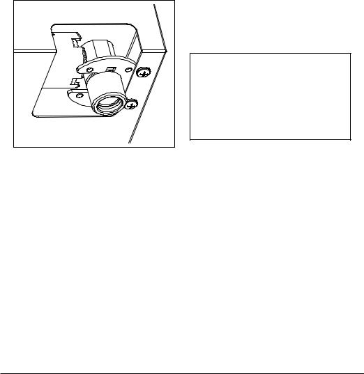
Gas connection (Fig. 10)
The connection to a gas tank or gas line must be made by a qualified person in conformity to current updated UNI-CIG 7129 and 7131 standards after making sure that the cook top is prepared for the type of gas available. If not, see: “Adapting to different types of gas”. Also check that the feed pressure falls within the values shown in the table: “User characteristics”.
Fig. 10 |
Metal rigid/semi-rigid hook-ups
Make the hook-up with metal fittings and pipes (even flexible hoses) so as not to stress the components inside the cook top.
Note: - After installation, use soapy water to check the perfect seal of the entire connection system.
Important note: make the connection using only metal fittings and pipes (flexible, continuous-wall steel hoses or rigid copper or steel tubing) and in such a way that its entire length can be inspected.
Electrical connection (Fig. 11)
The installer must be qualified and is responsible for correct electrical connections and following safety standards.
Prior to carrying out the electrical connection, please ensure that:
•the plant characteristics are such as to follow what is indicated on the matrix plate placed at the bottom of the working area;
•that the plant is fitted with an efficient earth connection, following the standards and law provisions in force.
The earth connectionis compulsory in terms of the |
|
law. |
|
Should there be no cable and/or plug on the equipment, |
|
use suitable absorption material for the working |
|
temperature as well, as indicated on the matrix |
|
plate. Under no circumstance must the cable reach a |
GB |
temperature above 50°C of the ambient temperature. |
|
If connecting directly to the mains power supply, fiit a |
|
|
|
multi-pole switch of a suitable size for the rated capacity |
|
with a clearance distance which completely disconnects |
|
the power line under overvoltage category III conditions, |
|
consistently with the rules of installation (the yellow/ |
|
green earth wir must not be interrupted). The plug or |
|
omnipolar switch must be easily reached on the installed |
|
equipment. |
|
Fig. 11
23
 Loading...