


 Loading...
Operating Manual - English
FUJITSU Server PRIMERGY RX1330 M4
Operating Manual
October 2018
Comments… Suggestions… Corrections…
The User Documentation Department would like to know your opinion of this manual. Your feedback helps us optimize our documentation to suit your individual needs.
Feel free to send us your comments by e-mail to manuals@ts.fujitsu.com.
Documentation creation according to DIN EN ISO 9001:2015
To ensure a consistently high quality standard and user-friendliness, this documentation was created to meet the regulations of a quality management system which complies with the requirements of the standard DIN EN ISO 9001:2015.
cognitas. Gesellschaft für Technik-Dokumentation mbH www.cognitas.de
Copyright and Trademarks
Copyright 2018 FUJITSU LIMITED
All rights reserved.
Delivery subject to availability; right of technical modifications reserved.
All hardware and software names used are trademarks of their respective manufacturers.
–The contents of this manual may be revised without prior notice.
–Fujitsu assumes no liability for damages to third party copyrights or other rights arising from the use of any information in this manual.
–No part of this manual may be reproduced in any without the prior written permission of Fujitsu.
Microsoft, Windows, Windows Server, and Hyper-V are trademarks or registered trademarks of Microsoft Corporation in the USA and other countries.
Intel and Xeon are trademarks or registered trademarks of Intel Corporation or its subsidiaries in the USA and other countries.

Before reading this manual
For your safety
This manual contains important information for safely and correctly using this product.
Carefully read the manual before using this product. Pay particular attention to the accompanying manual "Safety Notes and Regulations" and ensure that these safety notes are understood before using the product. Keep this manual and the "Safety Notes and Regulations" manual in a safe place for easy reference while using this product.
Radio interference
This product is a "Class A" ITE (Information Technology Equipment). In a domestic environment this product may cause radio interference, in which case the user may be required to take appropriate measures. VCCI-A
Aluminum electrolytic capacitors
The aluminum electrolytic capacitors used in the printed circuit board assemblies of the product and in the mouse and keyboard are limited-life components. Use of these components beyond their operating life may result in electrolyte leakage or depletion, potentially causing emission of foul odor or smoke.
As a guideline, in a normal office environment (25°C) operating life is not expected to be reached within the maintenance support period (5 years). However, operating life may be reached more quickly if, for example, the product is used in a hot environment. The customer shall bear the cost of replacing replaceable components which have exceeded their operating life. Note that these are only guidelines, and do not constitute a guarantee of trouble-free operation during the maintenance support period.
High safety use
This product has been designed and manufactured to be used in commercial and/or industrial areas as a server.
When used as visual display workplace, it must not be placed in the direct field of view to avoid incommoding reflections (applies only to TX server systems).
RX1330 M4 |
Operating Manual |

The device has not been designed or manufactured for uses which demand an extremely high level of safety and carry a direct and serious risk of life or body if such safety cannot be assured.
These uses include control of nuclear reactions in nuclear power plants, automatic airplane flight control, air traffic control, traffic control in mass transport systems, medical devices for life support, and missile guidance control in weapons systems (hereafter, "high safety use"). Customers should not use this product for high safety use unless measures are in place for ensuring the level of safety demanded of such use. Please consult the sales staff of Fujitsu if intending to use this product for high safety use.
Measures against momentary voltage drop
This product may be affected by a momentary voltage drop in the power supply caused by lightning. To prevent a momentary voltage drop, the use of an uninterruptible power supply is recommended.
(This notice follows the guidelines of Voltage Dip Immunity of Personal Computer issued by JEITA, the Japan Electronics and Information Technology Industries Association.)
Technology controlled by the Foreign Exchange and Foreign Trade Control Law of Japan
Documents produced by Fujitsu may contain technology controlled by the Foreign Exchange and Foreign Trade Control Law of Japan. Documents which contain such technology should not be exported from Japan or transferred to non-residents of Japan without first obtaining authorization in accordance with the above law.
Harmonic Current Standards
This product conforms to harmonic current standard JIS C 61000-3-2.
Only for Japan: About SATA HDDs
The SATA version of this server supports HDDs with SATA/BC-SATA storage interfaces. Please note that the usage and operation conditions differ depending on the type of HDD used.
Operating Manual |
RX1330 M4 |

For more information on the usage and operation conditions of each available type of HDD, see the following internet address: http://jp.fujitsu.com/platform/server/primergy/harddisk/
RX1330 M4 |
Operating Manual |

Operating Manual |
RX1330 M4 |

Content
1 |
Introduction . . . . . . . . . . . . . . . . . . . . . . . . . . . |
11 |
1.1 |
Notational conventions . . . . . . . . . . . . . . . . . . . . |
11 |
2 |
Before you start . . . . . . . . . . . . . . . . . . . . . . . . |
13 |
2.1 |
Documentation overview . . . . . . . . . . . . . . . . . . . |
13 |
3 |
Product description . . . . . . . . . . . . . . . . . . . . . . |
17 |
3.1Overview of the server . . . . . . . . . . . . . . . . . . . . . 18
3.2Features . . . . . . . . . . . . . . . . . . . . . . . . . . . . . 19
3.3Connectors, controls and indicators . . . . . . . . . . . . . 26
3.3.1 |
Connectors on the server . . . . . . . . . . . . . . . . . . . . 26 |
3.3.1.1Server front . . . . . . . . . . . . . . . . . . . . . . . . . . 26
3.3.1.2Server rear . . . . . . . . . . . . . . . . . . . . . . . . . . 28
3.3.2 |
Controls and indicators on the server front . . . . . . . . . . . 29 |
3.3.2.1Controls on the front panel . . . . . . . . . . . . . . . . . . 29
3.3.2.2Indicators on the front panel . . . . . . . . . . . . . . . . . 31
3.3.2.3Indicator on the ODD . . . . . . . . . . . . . . . . . . . . . 35
3.3.2.4 |
Indicators on the hot-plug HDD/SSD module . . . . . . . . 36 |
3.3.3Indicators on the server rear . . . . . . . . . . . . . . . . . . . 37
3.3.3.1Indicators on the I/O panel . . . . . . . . . . . . . . . . . . 37
3.3.3.2 |
Indicator on hot-plug PSU . . . . . . . . . . . . . . . . . . |
41 |
3.3.3.3 |
Indicator on FJBU . . . . . . . . . . . . . . . . . . . . . . |
42 |
4 |
Important information . . . . . . . . . . . . . . . . . . . . . |
43 |
4.1Safety instructions . . . . . . . . . . . . . . . . . . . . . . . 43
4.2 |
ENERGY STAR . . . . . . . . . . . . . . . . . . . . . . . . . |
51 |
4.3 |
CE conformity . . . . . . . . . . . . . . . . . . . . . . . . . |
52 |
4.4 |
FCC Class A Compliance Statement . . . . . . . . . . . . . |
53 |
4.5 |
Environmental protection . . . . . . . . . . . . . . . . . . . |
54 |
RX1330 M4 |
Operating Manual |

Content
5 |
Starting up . . . . . . . . . . . . . . . . . . . . . . . . . . . . 57 |
5.1Installation steps, overview . . . . . . . . . . . . . . . . . . . 58
5.2 |
Unpacking the server . . . . . . . . . . . . . . . . . . . . . . 60 |
5.3Installing the server in the rack . . . . . . . . . . . . . . . . . 61
5.3.1Installing the server in the rack . . . . . . . . . . . . . . . . . . 63
5.4Connecting cables . . . . . . . . . . . . . . . . . . . . . . . . 66
5.4.1Notes on connecting/disconnecting cables . . . . . . . . . . . . 66
5.4.2Connecting devices to the server . . . . . . . . . . . . . . . . . 67
5.4.3Connecting the power cord . . . . . . . . . . . . . . . . . . . . 68
5.4.3.1 |
Using cable ties (standard PSU) . . . . . . . . . . . . . . . 69 |
5.4.3.2Using the cable clamp . . . . . . . . . . . . . . . . . . . . . 70
5.5 |
Switching on the server for the first time . . . . . . . . . . . 71 |
5.6Configuring the server with
ServerView Installation Manager . . . . . . . . . . . . . . . . 72
5.6.1Configuring the server and installing the operating system . . . . 72
5.6.1.1 |
Configuring the controllers . |
. . . . . . . |
. . . . . |
. . |
. |
. |
. |
73 |
5.6.1.2 |
Installing the operating system |
. . . . . . |
. . . . . |
. . |
. |
. |
. |
73 |
5.7Configuring the server without
ServerView Installation Manager . . . . . . . . . . . . . . . . 74
5.7.1Configuring the server and installing the operating system . . . . 74
5.7.1.1 |
Configuring the onboard SAS/SATA controller |
. . |
. |
. |
. |
. |
. |
. 74 |
5.7.1.2 |
Installing the operating system . . . . . . . |
. . . |
. |
. |
. |
. |
. |
. 74 |
5.8Notes on configuring controllers . . . . . . . . . . . . . . . . 75
5.8.1Notes on onboard SATA controllers . . . . . . . . . . . . . . . . 75
5.8.2 |
Notes on SAS/SATA RAID controllers . . . . . . . . . . . . . . 75 |
|
5.9 |
Note on operating system . . . . . . . . . . . . . . . . . . . 76 |
|
6 |
Operation . . . . . . . . . . . . . . |
. . . . . . . . . . . . . . . 77 |
6.1 |
Switching the server on and off . |
. . . . . . . . . . . . . . . 77 |
6.2Installing HDD/SSD modules . . . . . . . . . . . . . . . . . . 80
6.2.1 |
Installing 2.5-inch HDD/SSD modules . . . . . . . |
. . . . . . . 80 |
6.2.1.1 |
Removing a 2.5-inch HDD/SSD dummy module |
. . . . . . . 80 |
6.2.1.2 |
Installing a 2.5-inch HDD/SSD module . . . . . |
. . . . . . . 81 |
6.2.2 |
Installing 3.5-inch HDD modules . . . . . . . . . . |
. . . . . . . 82 |
6.2.2.1Removing a 3.5-inch HDD dummy module . . . . . . . . . . 82
Operating Manual |
RX1330 M4 |

Content
6.2.2.2 |
Installing a 3.5-inch HDD module . . . . . . . . . . . . . . |
82 |
6.3 |
Installing a second PSU . . . . . . . . . . . . . . . . . . . . |
84 |
6.3.1Removing the dummy cover . . . . . . . . . . . . . . . . . . . 84
6.3.2 |
Installing a PSU . . . . . . . . . . . . . . . . . . . . . . . . . |
84 |
6.4 |
Cleaning the server . . . . . . . . . . . . . . . . . . . . . . |
86 |
7 |
Troubleshooting and tips . . . . . . . . . . . . . . . . . . . |
87 |
8 |
Technical data . . . . . . . . . . . . . . . . . . . . . . . . . |
95 |
9 |
Warranty and service . . . . . . . . . . . . . . . . . . . . . . 105 |
|
RX1330 M4 |
Operating Manual |

Content
Operating Manual |
RX1330 M4 |
1 Introduction
This operating manual describes how to install, set up and operate your server.
This operating manual is intended for those responsible for installing the hardware and ensuring that the system runs smoothly. It contains all the information you need to put your PRIMERGY RX1330 M4 into operation.
To understand the various expansion options, you will need to be familiar with the fields of hardware and data transmission and you will require a basic knowledge of the underlying operating system.
1.1Notational conventions
The following notational conventions are used in this manual:
Text in bold |
Indicates references to names of interface elements. |
|
|
Text in |
Indicates commands. |
monospace |
|
|
|
"Quotation marks" |
Indicate names of chapters and terms that are being |
|
emphasized. |
Ê |
Describes activities that must be performed in the order |
|
shown. |
|
|
VCAUTION! |
Pay particular attention to texts marked with this symbol. |
Failure to observe this warning may endanger your life, |
|
|
destroy the system or lead to the loss of data. |
IIndicates additional information, notes and tips.
RX1330 M4 |
Operating Manual |
11 |

Introduction
12 |
Operating Manual |
RX1330 M4 |

2 Before you start
Before you start to install, set up and operate your server, please proceed as follows:
ÊCarefully read the safety instructions in chapter "Important information" on page 43.
2.1Documentation overview
To get an overview on all documents for your server, see the following table.
IAll documentation on PRIMERGY hardware and ServerView software is available online from the Fujitsu manuals server at: http://manuals.ts.fujitsu.com
For Japan: http://www.fujitsu.com/jp/products/computing/servers/primergy/manual/
The complete PRIMERGY documentation set can also be downloaded as a DVD ISO image at: ftp://ftp.ts.fujitsu.com/images/serverview/manuals
For Japan: http://www.fujitsu.com/jp/products/computing/servers/primergy/downloa ds/
Document |
Description |
|
"Safety Notes and Regulations" |
Important safety information, available |
|
manual |
online, or as a printed copy |
|
" " for Japan |
||
|
||
|
|
|
"FUJITSU Server PRIMERGY |
Information how to install, set up and |
|
RX1330 M4 Operating Manual" |
operate your server, available online |
|
"FUJITSU Server PRIMERGY |
Instructions for upgrading the server |
|
RX1330 M4 Upgrade and |
configuration or replacing defective |
|
Maintenance Manual" |
hardware, available online |
|
|
|
|
"D3675 BIOS Setup Utility for |
Information on configurable BIOS options |
|
FUJITSU Server PRIMERGY |
||
and parameters, available online |
||
RX1330 M4 Reference Manual" |
||
|
|
Table 1: Documentation overview
RX1330 M4 |
Operating Manual |
13 |

Before you start
Document |
Description |
|
|
|
|
System foil |
Label inside the top cover outlining |
|
connectors, indicators and jumper |
||
|
||
|
Various system information, such as the |
|
|
product name, serial number, order |
|
|
number, MAC addresses and DNS name |
|
ID card |
(for Japan, only the product name and the |
|
|
serial number) |
|
|
The location of the ID card can be found in |
|
|
the overview of the server. |
|
|
– "ServerView Suite Local Service |
|
|
Concept (LSC)" user guide |
|
|
– "ServerView Operations Manager - |
|
|
Server Management" user guide |
|
|
– "iRMC S5 - Concepts and Interfaces“ |
|
Software documentation |
user guide |
|
|
– "iRMC S5 - Configuration and |
|
|
Maintenance" user guide |
|
|
– "iRMC S5 - Web Interface" user guide |
|
|
– "ServerView embedded Lifecycle |
|
|
Management (eLCM)" user guide |
|
|
|
|
|
Spare parts identification and information |
|
|
system (not valid for Japan), available for |
|
Illustrated Spares catalog |
online use or download (Windows OS) at |
|
http://manuals.ts.fujitsu.com/illustrated_sp |
||
|
||
|
ares or from the CSS component view of |
|
|
the ServerView Operations Manager |
|
Glossary |
Contains abbreviations and explanations, |
|
available online |
||
|
||
"Warranty" manual |
Important information on warranty |
|
" " for Japan |
regulations, recycling and service, |
|
available online, or as a printed copy |
||
|
|
Table 1: Documentation overview
14 |
Operating Manual |
RX1330 M4 |
|
|
Before you start |
|
|
|
Document |
Description |
|
|
|
|
"Returning used devices" |
Recycling and contact information, |
|
manual |
available online at |
|
|
http://ts.fujitsu.com/recycling, or as a |
|
|
||
"Service Desk" leaflet |
printed copy |
|
" " for Japan |
Not applicable in Japan and other countries |
|
|
that have different regulations for recycling |
|
|
RAID documentation, available online at |
|
|
http://manuals.ts.fujitsu.com under x86 |
|
|
Servers - Expansion Cards - Storage |
|
Additional documentation |
Adapters |
|
|
For Japan: |
|
|
http://www.fujitsu.com/jp/products/computi |
|
|
ng/servers/primergy/manual/ |
|
|
|
|
|
– |
Operating system documentation, |
Third party documentation |
|
online help |
|
– |
Peripherals documentation |
Table 1: Documentation overview
RX1330 M4 |
Operating Manual |
15 |

Before you start
16 |
Operating Manual |
RX1330 M4 |

3 Product description
This section provides an overview of the server and information on the features of the PRIMERGY RX1330 M4 server.
The PRIMERGY RX1330 M4 server is available as a rack model.
RX1330 M4 |
Operating Manual |
17 |

Product description
3.1Overview of the server
Figure 1: Server front |
Pos. |
Component |
|
1 |
ODD |
|
|
|
|
2 |
ID card |
|
|
|
|
3 |
Front panel module (not on 10x HDD/SSD version) |
|
|
|
|
|
HDD/SSD: |
|
|
4x |
3.5-inch HDD OR |
4 |
8x |
2.5-inch HDD/SSD OR |
|
4x |
2.5-inch PCIe SSD and 4x 2.5-inch HDD/SSD OR |
|
10x 2.5-inch HDD/SSD |
|
5 Front panel on QRL (only on 10x HDD/SSD version)
18 |
Operating Manual |
RX1330 M4 |

Product description
3.2Features
Customer Self Service (CSS)
The PRIMERGY Customer Self Service (CSS) concept enables you to identify and replace the affected component yourself in the case of certain error scenarios.
In the CSS concept, you can replace the following components yourself in the event of an error:
–Hot-plug HDD/SSD modules
–Hot-plug PSUs
–Memory modules
–System fans
–Expansion cards
For more information on replacing these components, see the "FUJITSU Server PRIMERGY RX1330 M4 Upgrade and Maintenance Manual".
CSS indicators on the front panel and I/O panel of the PRIMERGY server provide you with information if a CSS event arises.
In addition, CSS errors are displayed in the ServerView Operations Manager, the server management software from Fujitsu.
In the event of errors, the ServerView Operations Manager refers you directly to the affected component and its order information in the Illustrated Spares catalog of the server in question. (This feature is not available for Japan.)
IMore information on the CSS concept is provided in the "PRIMERGY ServerView Suite Local Service Concept - LSC" manual on the Fujitsu manuals server.
For the latest information on optional products provided for the RX1330 M4, see the configurator tool of the server: http://ts.fujitsu.com/products/standard_servers/index.html
For Japan: http://www.fujitsu.com/jp/products/computing/servers/primergy/
RX1330 M4 |
Operating Manual |
19 |

Product description
System board
The features of the system board are described in the "FUJITSU Server PRIMERGY RX1330 M4 Upgrade and Maintenance Manual". The setup possibilities are described in the "D3675 BIOS Setup Utility for FUJITSU Server PRIMERGY RX1330 M4 Reference Manual".
Trusted Platform Module (TPM)
A TPM for safer storage of keys can be implemented as an option. This module enables programs from third party manufacturers to store key information (e.g. drive encryption using Windows Bitlocker Drive Encryption).
The TPM is activated via the BIOS (for more information, see the “D3675 BIOS Setup Utility for FUJITSU Server PRIMERGY RX1330 M4 Reference Manual").
VCAUTION!
–When using the TPM, note the program descriptions provided by the third party manufacturers.
–You must also create a backup of the TPM content. To do this, follow the third party manufacturer instructions. Without this backup, if the TPM or the system board is faulty, you will not be able to access your data.
–If a failure occurs, please inform your service about the TPM activation before it takes any action, and be prepared to provide them with your backup copies of the TPM content.
20 |
Operating Manual |
RX1330 M4 |
Product description
Power supply unit (PSU)
The server can be equipped with:
–One standard PSU
The PSU adjusts automatically to any mains voltage in the range of 100 V - 240 V.
–Up to two hot-plug PSUs
The hot-plug PSU adjusts automatically to any mains voltage in the range 100 V - 240 V. In addition, a second hot-plug PSU can be installed optionally to serve as a redundant power supply. If one PSU fails, the second PSU in the redundant configuration ensures operation can continue uninterrupted and the defective PSU can be replaced during operation (hot-plug).
–One hot-plug PSU and one FJBU
Fujitsu battery unit (FJBU)
FJBU behaves as a modular UPS in the server. When power fail happened, the server can operate by FJBU for a while. FJBU supports hot-plugging, and can be replaced during operation.
Advanced Thermal Design (ATD)
The ATD option allows you to operate the system with a wider temperature range either of 5 °C to 40 °C or 5 °C to 45 °C, depending on your system and configuration.
This option can only be ordered from the manufacturer and is indicated by the respective logo on the identification rating plate.
VCAUTION
In a system that is configured with ATD, only certain components which support the respectively increased higher operating temperature range may be installed and used. For applicable restrictions, see the official configurator tool.
High level of availability and data security
When memory data is accessed, 1-bit errors are identified in the main memory and automatically corrected with the Error Correcting Code (ECC) method.
RX1330 M4 |
Operating Manual |
21 |

Product description
Automatic Server Reconfiguration and Restart (ASR&R) restarts the system in the event of an error and automatically "hides" the defective system components.
The Prefailure Detection and Analysis (PDA) technology from Fujitsu analyzes and monitors all components that are critical for system reliability.
A RAID controller supports different RAID levels and increase the availability and data security of the system.
The HDD/SSD modules provide additional availability.
iRMC S5 with integrated management LAN connector
The iRMC S5 (integrated Remote Management Controller) is a Baseboard Management Controller (BMC) with integrated management LAN connector and expanded functionality that was previously only available with additional plug-in cards. In this way, the iRMC S5 enables complete control of PRIMERGY servers, regardless of system status, and thus particularly the control of PRIMERGY servers that are in the "out-of-band" system status.
Major functions supported by the iRMC S5 include the following:
●Browser access via the own Web server of the iRMC S5
●Secure communication (SSH, SSL)
●Power Management for the managed server (depending on its system status)
●Power Consumption Management
●Connecting virtual drives as remote storage
●Text-based and graphic console bypass (Advanced Video Redirection)
●Remote Storage
●Command Line Interface (CLI)
●Simple, interactive or script-based iRMC S5configuration
●Customer Self Service (CSS)
●User management of the iRMC S5
●Multi-computer, global iRMC S5 user administration using an LDAP Directory Service
●Automatic network configuration via DNS / DHCP
22 |
Operating Manual |
RX1330 M4 |

Product description
●Power supply of the iRMC S5 via the system standby supply
●Full-coverage alarm management
●System Event Log (SEL) reading and processing
●IPMI support
●CIM / WS-MAN support
●Internal Event Log for user login / logout auditing
More information about the iRMC S5 can be found in the iRMC S5 user guides (on the Fujitsu manuals server under x86 Servers - Software -
ServerView Suite - Out-Of-Band Management).
Server management
Server management is implemented using the ServerView Operations Manager supplied and the PDA technology from Fujitsu. PDA reports the threat of a system error or overload at an early stage, allowing preventive measures to be taken.
The ServerView Operations Manager enables the management of all PRIMERGY servers in the network via a central console. The ServerView Operations Manager supports the following functions:
●Round-the-clock monitoring, regardless of server status
●High-performance, graphical console bypass (AVR) protected by HTTPS/SSL (128 bit)
●Remote storage via USB
●Remote power on
●Intrusion detection in the floorstand model
●Temperature monitoring of the CPU and the surrounding area
●Detailed status and error reports for CPUs and main memory
●Watchdog timer for Automatic Server Reconfiguration and Restart (ASR&R) in the event that memory modules or CPUs fail
●Power monitoring
●End-of-life monitoring of fans with prompt notification before failure
●Watchdog timer for monitoring the operating system with ASR&R
RX1330 M4 |
Operating Manual |
23 |

Product description
More information on the ServerView Operations Manager is provided in the associated documentation.
ServerView Installation Manager
You can configure the PRIMERGY server quickly and precisely with the ServerView Installation Manager software provided. User-guided menus are available for installing the server operating system (for more information, see section "Notes on configuring controllers" on page 75).
Service and support
PRIMERGY servers are easy to maintain and modular, thus enables quick and simple maintenance.
The handles and locks (touch points) used to exchange components are colored green to ensure simple and immediate recognition.
In order to prevent the components from being damaged by incorrect handling when they are being installed and removed, the areas of all components that can be touched without damaging them are also marked green.
PRIMERGY diagnostic LEDs fitted on the system board indicate which component (memory module, CPU, fan or expansion card) is not functioning properly.
The Flash EPROM program supplied with the Fujitsu utilities supports a fast BIOS update.
With the iRMC on the system board, the server can also be maintained and serviced remotely. This enables remote diagnosis for system analysis, remote configuration and remote restart should the operating system or hardware fail.
ServerView Remote Management
ServerView Remote Management is the remote management solution from Fujitsu for PRIMERGY servers. ServerView Remote Management and the relevant hardware components integrated on the system board allow remote monitoring and maintenance as well as fast restoration of operation in the event of errors.
Remote monitoring and maintenance avoids time-consuming and costly on-site repairs and reduces service costs. This leads to a reduction in the total cost of ownership and an excellent return on investment for the remote management solution.
24 |
Operating Manual |
RX1330 M4 |

Product description
The administrator can access all system information and information from the sensors such as fan speeds or voltages via the iRMC web interface. You can also start the text-based or graphic console bypass (Advanced Video Redirection, AVR) and connect virtual drives as remote storage.
IMore information about the iRMC can be found in the iRMC user guides at http://manuals.ts.fujitsu.com under x86 Servers - Software -
ServerView Suite - Out-Of-Band Management.
Property and data protection
The rack model is protected against unauthorized access by a lockable rack door.
BIOS setup security functions
The Security menu in BIOS Setup offers various options for protecting your data from unauthorized access. By combining these options, you can also achieve optimum protection for your system.
IA detailed description of the Security menu and how to assign passwords can be found in the "D3675 BIOS Setup Utility for FUJITSU Server PRIMERGY RX1330 M4 Reference Manual".
RX1330 M4 |
Operating Manual |
25 |

Product description
3.3Connectors, controls and indicators
3.3.1Connectors on the server
3.3.1.1Server front
Figure 2: Connectors on the front panel module
12x USB 3.1 Gen 1 connectors
A front VGA connector is available as an option.
26 |
Operating Manual |
RX1330 M4 |
Product description
10 HDD/SSD variant
Figure 3: Connectors on the front panel on QRL
11x USB 2.0 connector
The USB 2.0 connector on the front supports activities carried out by the service technician. The maximum length of the external cable is two meters for the USB connector on the front.
RX1330 M4 |
Operating Manual |
27 |
Product description
3.3.1.2Server rear
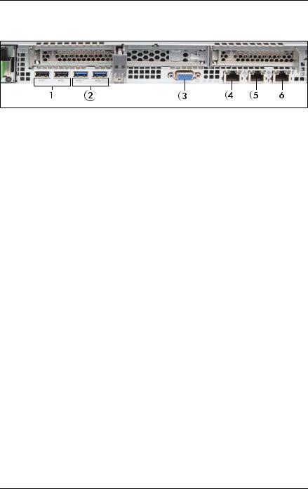
Figure 4: Connectors on the I/O panel
1 |
2 x USB 2.0 connectors |
4 |
Standard LAN connector (LAN1) |
|
|
|
|
2 |
2 x USB 3.1 Gen 2 |
5 |
Shared LAN connector (LAN2) |
|
connectors |
|
|
|
|
|
|
3 |
Video connector (VGA) |
6 |
Management LAN connector (for |
|
|
|
iRMC server management function) |
|
|
|
|
The corresponding indicators are explained in section "Indicators on the server rear" on page 37.
IDepending on the BIOS settings, the shared LAN connector may also be used as a management LAN connector. For more information, see the corresponding BIOS Setup Utility reference manual.
ISome of the devices connected require special software (e.g. drivers) (see documentation for the connected device).
28 |
Operating Manual |
RX1330 M4 |
Product description
3.3.2Controls and indicators on the server front
3.3.2.1Controls on the front panel
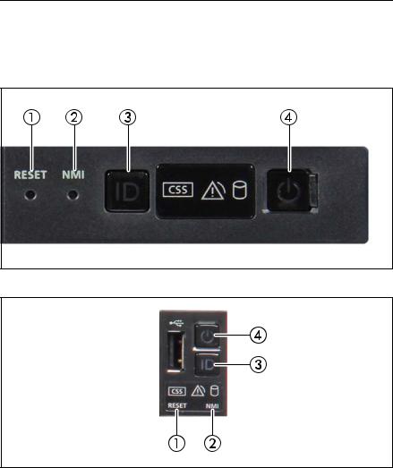
Figure 5: Controls on the front panel module
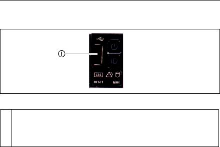
Figure 6: Controls on the front panel on QRL
RX1330 M4 |
Operating Manual |
29 |

Product description
Pos. |
Label |
Button |
Function |
||
|
|
|
|
|
|
|
|
|
|
Reboots the system. |
|
|
|
|
|
Press the reset button with a straightened |
|
1 |
RESET |
Reset button |
end of a paper clip. |
||
|
|
|
|
VCAUTION! |
|
|
|
|
|
Risk of data loss! |
|
|
|
|
|
Used to troubleshoot software and device |
|
|
|
|
|
driver errors. |
|
|
|
|
|
Press the NMI button with a straightened end |
|
2 |
NMI |
NMI button |
of a paper clip. |
||
VCAUTION! |
|||||
|
|
|
|
Use this button only if directed to do so |
|
|
|
|
|
by qualified certified maintenance |
|
|
|
|
|
personnel! |
|
3 |
ID |
ID button |
Highlights the ID indicator on the front panel |
||
and I/O panel for easy server identification. |
|||||
|
|
|
|
||
|
|
|
|
|
|
|
|
|
|
Used to switch the server on or off. |
|
|
|
|
On/Off |
If the system is running an ACPI- |
|
4 |
|
|
Icompliant operating system, pressing |
||
|
|
button |
|||
|
|
|
the On/Off button will perform a |
||
|
|
|
|
||
|
|
|
|
graceful shutdown. |
|
|
|
|
|
|
|
30 |
Operating Manual |
RX1330 M4 |
Loading...