


UE12A33A
Friedrich UE12A33A, US12A30A, UE10A33A, US10A30A, US12A10A Service Manual
...
US08/US10/US12/UE08/UE10/UE12 (2/03)
Thru-the-Wall Series
Thru-the-Wall Series
Service and Parts
Manual
115 Volts UE08A13A US08A10A US10A10A US12A10A
230 Volts US10A30A UE10A33A US12A30A UE12A33A

—2—
1. PREFACE
1.1 SAFETY PRECAUTIONS ...............................2
1.2 INSULATION RESISTANCE TEST.................2
1.3 SPECIFICATIONS ..........................................3
1.4 FEATURES.....................................................6
1.5 CONTROL LOCATIONS.................................6
2.
DISASSEMBLY INSTRUCTIONS
2.1 MECHANICAL PARTS....................................8
2.1.1 FRONT GRILLE.....................................8
2.1.2 CABINET................................................8
2.1.3 CONTROL BOX.....................................8
2.2 AIR HANDLING PARTS..................................9
2.2.1
ORIFICE, HEATER ASSY AND TURBO FAN
.........9
2.2.2 FAN........................................................9
2.2.3 SHROUD..............................................10
2.3 ELECTRICAL PARTS...................................10
2.3.1 MOTOR................................................10
2.3.2 COMPRESSOR...................................10
2.3.3 CAPACITOR........................................10
2.3.4 POWER CORD....................................11
2.3.5 THERMOSTAT ....................................11
2.3.6 ROTARY SWITCH...............................11
2.4 REFRIGERATION CYCLE............................12
2.4.1 CONDENSER......................................12
2.4.2 EVAPORATOR....................................12
2.4.3 CAPILLARY TUBE...............................12
3.
INSTALLATION
3.1 INSTALLATION REQUIREMENTS...............15
3.2 INSTALLATION.............................................16
3.3 PROCEDURE A............................................17
3.4 PROCEDURE B............................................18
3.5 PROCEDURE C............................................20
3.4 ELECTRICAL REQUIREMENTS..................22
3.4.1
ELECTRICAL DATA(FOR 115V MODEL)
.....22
3.4.2
ELECTRICAL DATA(FOR 230V/208 MODEL)
......22
3.4.3 ELECTRICAL SAFETY........................22
4.
TROUBLESHOOTING GUIDE
4.1 OUTSIDE DIMENSIONS...............................23
4.2 PIPING SYSTEM ..........................................23
4.3 TROUBLESHOOTING GUIDE......................24
5. SCHEMATIC DIAGRAM
5.1 CIRCUIT DIAGRAM......................................29
6. EXPLODED VIEW..................................31
7. REPLACEMENT PARTS LIST.......32
1. PREFACE
This
SERVICE MANUAL provides various service information, including the mechanical and electrical
parts etc. This room air conditioner was manufactured and assembled under a strict quality control system.
The refrigerant is charged at the factory. Be sure to read the safety precautions prior to servicing the unit.
1.1 SAFETY PRECAUTIONS
1. When servicing the unit, set the ROTARY SWITCH
or POWER SWITCH to OFF(O) and unplug the
power cord.
2. Observe the original lead dress.
If a short circuit is found, replace all parts which
have been overheated or damaged by the short
circuit.
3. After servicing the unit, make an insulation
resistance test to protect the customer from being
exposed to shock hazards.
1.2
INSULATION RESISTANCE TEST
1. Unplug the power cord and connect a jumper
between 2 pins (black and white).
2. The grounding conductor (green or green & yellow)
is to be open.
3. Measure the resistance value with an ohm meter
between the jumpered lead and each exposed
metallic part on the equipment at all the positions
(except OFF or O) of the ROTARY SWITCH.
4. The value should be over 1MΩ.
CONTENTS
—3—
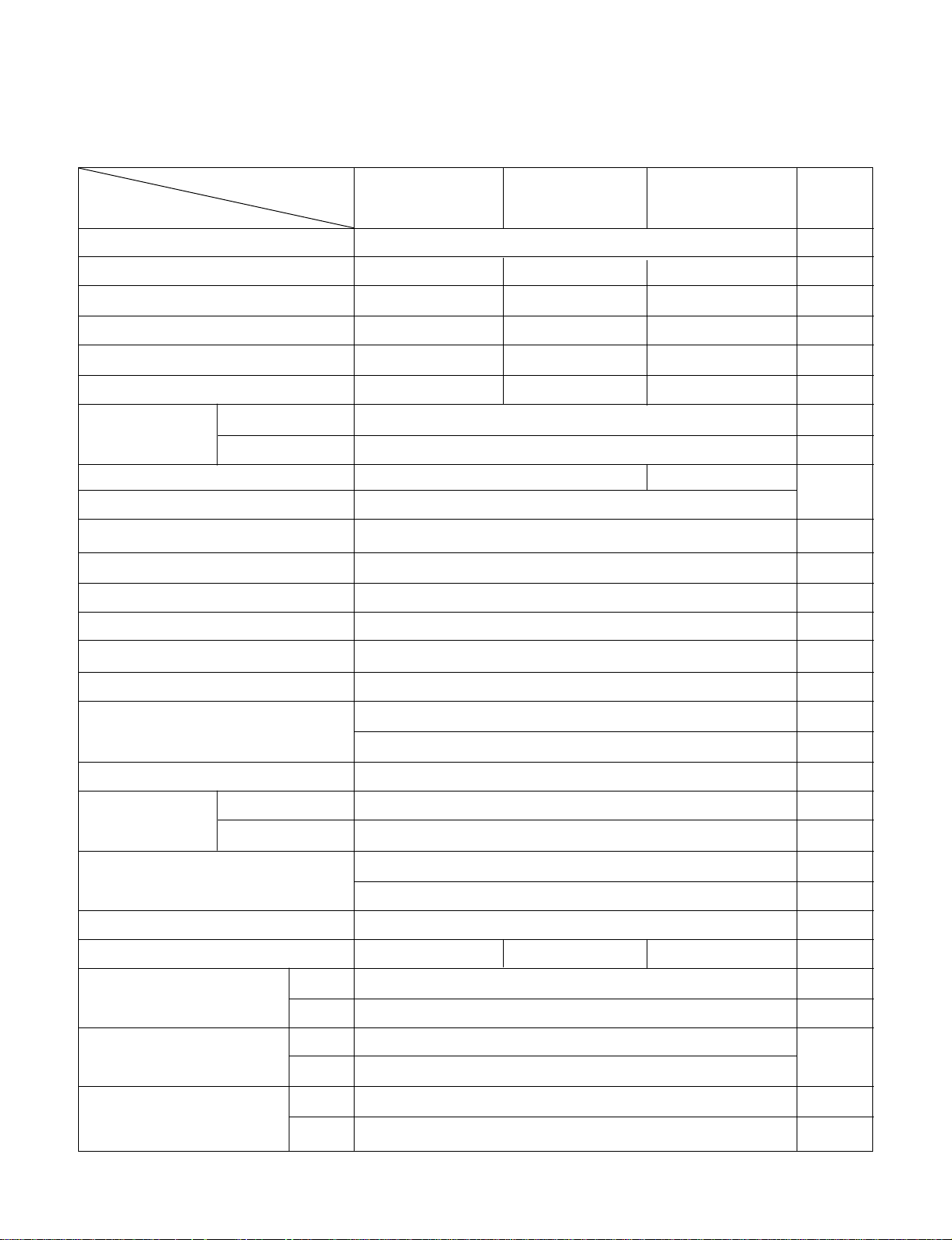
1.3 SPECIFICATIONS
1.3.1 FOR US08A10A/ US10A10A/ US12A10A
US08A10A US10A10A US12A10A
REMARK
MODELS
ITEMS
AIR DIRECTION CONTROL
PROTECTOR
POWER CORD
OPERATING
TEMPERATURE
LOUVERED-
FIN TYPE
OPTIONAL
PART
2 ROW 17 STACKS, L-BENDED TYPE
EXTERNAL OVERLOAD PROTECTOR
POWER SUPPLY
1Ø, 115V, 60Hz
COOLING CAPACITY (Btu/h) 8,000 10,000 11,700
INPUT (W) 800 1,050 1,230
RUNNING CURRENT (A) 7.5 9.8 11.5
E.E.R (Btu/w.h) 10.0 9.5 9.5
REFRIGERANT (R-22) CHARGE(g) 425(15.0 OZ) 410(14.5 OZ) 475(16.8 OZ)
INDOOR (°C) 26.7(DB) 19.4(WB)
OUTDOOR (°C) 35(DB) 23.9(WB)
EVAPORATOR 2 ROW 12 STACKS 2 ROW 11 STACKS
CONDENSER
FAN, INDOOR TURBO FAN
FAN, OUTDOOR PROPELLER TYPE FAN WITH SLINGER-RING
FAN SPEEDS, FAN/COOLING 2/3
FAN MOTOR 6 POLES
OPERATION CONTROL ROTARY SWITCH
ROOM TEMP. CONTROL THERMOSTAT
VERTICAL LOUVER(RIGHT & LEFT)
HORIZONTAL LOUVER(UP & DOWN)
CONSTRUCTION TOP-DOWN
COMPRESSOR
FAN MOTOR INTERNAL THERMAL PROTECTOR
1.6m (3WIRE WITH GROUNDING)
ATTACHMENT PLUG(CORD-CONNECTED TYPE)
DRAIN SYSTEM SPLASHED BY FAN SLINGER
NET WEIGHT (lbs/kg) 72/33 79/36 80/37
DIMENSION (inch)
(W x H x D) (mm)
SLEEVE DIMESION (inch)
(W x H x D) (mm)
SLEEVE DEPTH (inch)
WITH FRONT GRILLE (mm)
24
21
/
32 x 14
13
/
32 x 19
21
/
32
626 x 366 x 499
25
7
/8 x 15
17
/32 x 16
23
/32
656 x 394 x 425
20
510
—4—
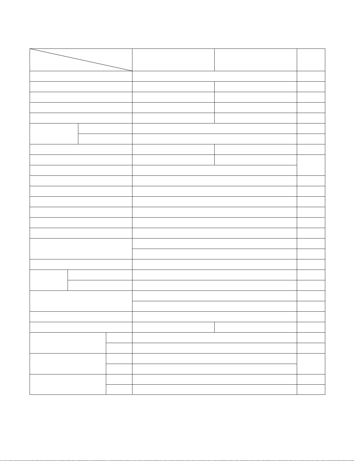
1.3.2 FOR US10A30A/US12A30A
REMARK
POWER SUPPLY
COOLING CAPACITY (Btu/h)
INPUT (W)
RUNNING CURRENT
(A)
E.E.R. (Btu/W.h)
INDOOR (°C)
OUTDOOR (°C)
REFRIGERANT (R-22) CHARGE(g)
EVAPORATOR
CONDENSER
FAN, INDOOR
FAN, OUTDOOR
FAN SPEEDS (FAN/COOLING/HEATING)
FAN MOTOR
OPERATION CONTROL
ROOM TEMP. CONTROL
CONSTRUCTION
COMPRESSOR
FAN MOTOR
DRAIN SYSTEM
NET WEIGHT (lbs/kg)
DIMENSION (inch)
(W x H x D) (mm)
SLEEVE DIMESION (inch)
(W x H x D) (mm)
SLEEVE DEPTH (inch)
WITH FRONT GRILLE (mm)
1Ø, 208/ 230V, 60Hz
9,800/10,000 11,400/11,700
1,030/1,050 1,200/1,230
5.2/4.7 6.2/5.8
9.5 9.5
26.7 (DB) 19.4 (WB)
35 (DB) 23.9 (WB)
440(15.5 OZ) 465(16.4 OZ)
2 ROW 12 STACKS 2 ROW 11 STACKS
2 ROW 17 STACKS, L-BENDED TYPE
TURBO FAN
PROPELLER TYPE FAN WITH SLINGER-RING
2/3
6 POLES
ROTARY SWITCH
THERMOSTAT
VERTICAL LOUVER (RIGHT & LEFT)
HORIZONTAL LOUVER (UP & DOWN)
TOP-DOWN
EXTERNAL OVERLOAD PROTECTOR
INTERANL THERMAL PROTECTOR
1.6m (3 WIRE WITH GROUDING)
ATTACHMENT PLUG (CORD-CONNECTED TYPE)
SPLASHED BY FAN SLINGER
80/36 80/37
24
21
/
32 x 14
13
/
32 x 19
21
/
32
626 x 366 x 499
25
7
/
8
x 15
17
/32
x 16
23
/32
656 x 394 x 425
20
510
MODELS
ITEMS
OPERATING
TEMPERA-TURE
AIR DIRECTION CONTROL
POWER CORD
PROTECTOR
LOUVERED-
FIN TYPE
US10A30 US12A30
OPTIONAL
PART
REMARK
POWER SUPPLY
CAPACITY (Btu/h)
INPUT (W)
RUNNING CURRENT
(A)
E.E.R. (Btu/W.h)
CAPACITY (Btu/h)
INPUT (W)
RUNNING CURRENT
(A)
INDOOR (°C)
OUTDOOR (°C)
INDOOR (°C)
OUTDOOR (°C)
REFRIGERANT (R-22) CHARGE(g)
EVAPORATOR
CONDENSER
FAN, INDOOR
FAN, OUTDOOR
FAN SPEEDS (FAN/COOLING/HEATING)
FAN MOTOR
OPERATION CONTROL
ROOM TEMP. CONTROL
CONSTRUCTION
ELECTRIC HEATER
COMPRESSOR
FAN MOTOR
ELECTRIC HEATER
DRAIN SYSTEM
NET WEIGHT (lbs/kg)
DIMENSION (inch)
(W x H x D) (mm)
SLEEVE DIMESION (inch)
(W x H x D) (mm)
SLEEVE DEPTH (inch)
WITH FRONT GRILLE (mm)
—5—
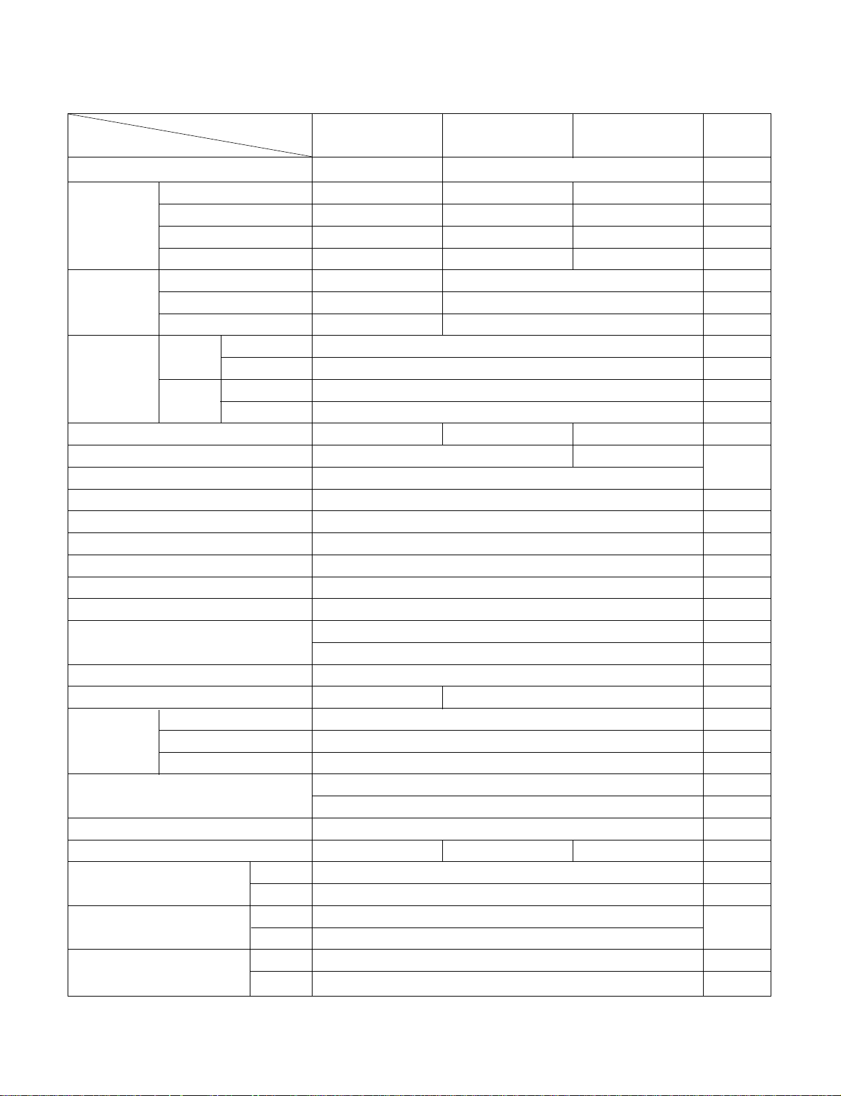
1.3.3 FOR UE08A13A/UE10A33A/UE12A33A
1Ø, 115V, 60Hz 1Ø, 208/ 230V, 60Hz
8,000 9,800/10,000 11,400/11,700
800 1,030/1,050 1,200/1,230
7.5 5.2/4.7 6.2/5.8
10.0 9.5 9.5
3,850 9,200/11,200
1,230 2,900/3,500
10.7 14.0/15.3
26.7 (DB) 19.4 (WB)
35 (DB) 23.9 (WB)
21.1 (DB) 15.6 (WB)
8.3 (DB) 6.1 (WB)
425(15.0 OZ) 440(15.5 OZ) 465(16.4 OZ)
2 ROW 12 STACKS 2 ROW 11 STACKS
2 ROW 17 STACKS, L-BENDED TYPE
TURBO FAN
PROPELLER TYPE FAN WITH SLINGER-RING
1/ 2/ 2
6 POLES
ROTARY SWITCH
THERMOSTAT
VERTICAL LOUVER (RIGHT & LEFT)
HORIZONTAL LOUVER (UP & DOWN)
TOP-DOWN
1.2KW, 115V 3.5KW, 208/230V
EXTERNAL OVERLOAD PROTECTOR
INTERANL THERMAL PROTECTOR
FUSE LINK, BIMETAL THERMOSTAT
1.6m (3 WIRE WITH GROUDING)
ATTACHMENT PLUG (CORD-CONNECTED TYPE)
SPLASHED BY FAN SLINGER
73/33 80/36 81/37
24
21
/32 x 14
13
/32 x 19
21
/32
626 x 366 x 499
25
7
/8 x 15
17
/32 x 16
23
/32
656 x 394 x 425
20
510
MODELS
ITEMS
OPERATING
TEMPERA-
TURE
AIR DIRECTION CONTROL
POWER CORD
PROTECTOR
HEATING
COOLING
COOLING
HEATING
LOUVERED-
FIN TYPE
UE08A13A UE10A33A UE12A33A
OPTIONAL
PART
1.4 FEATURES
• Designed for cooling only.
• Powerful and quiet cooling.
• Top-down chassis for the simple installation and service.
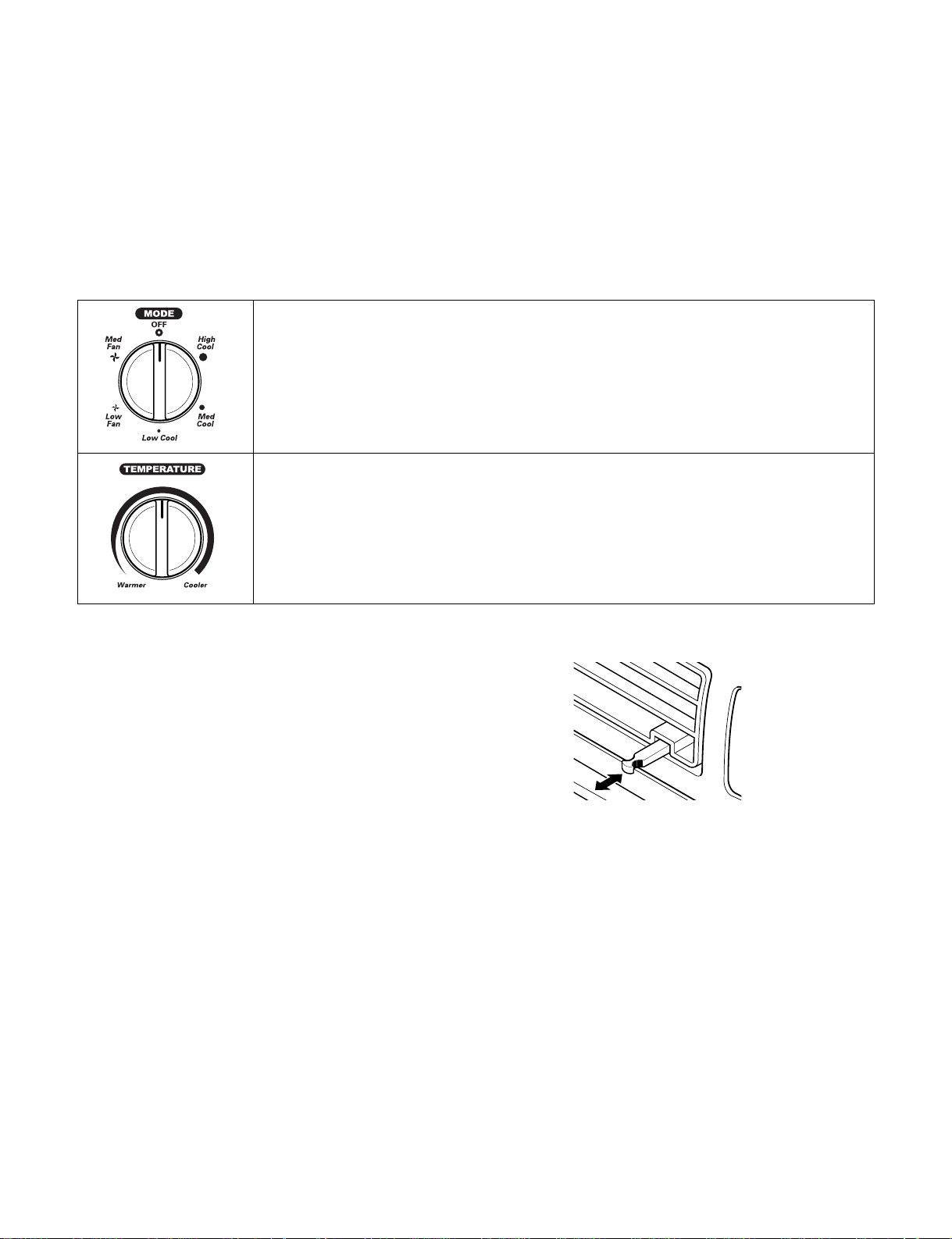
1.5 CONTROL LOCATIONS
1.5.1 COOLING ONLY MODEL
• OPERATION
• VENTILATION
Push the lever to the "CLOSE" position to cool, heat or
recirculate room air only.
Pull the lever to the "OPEN" position to exhaust smoke or
stale air from the room.
This feature is best used in conjunction with the FAN ONLY
position.
• Side air-intake, side cooled-air discharge.
• Built in adjustable THERMOSTAT.
• Washable one-touch filter.
• Compact size.
—6—
PULL OPEN / PUSH CLOSE
Off - Turns air conditioner off.
Med Fan Only - Med speed fan operation without cooling.
Low Fan Only - Low speed fan operation without cooling.
High Cool - Cooling with high speed fan operation.
Med Cool - Cooling with med speed fan operation.
Low Cool - Cooling with low speed fan operation.
This automatically controls the temperature of the indoor air.
Turn the knob clockwise for greater cooling.
Turn the knob counter-clockwise for more moderate cooling.
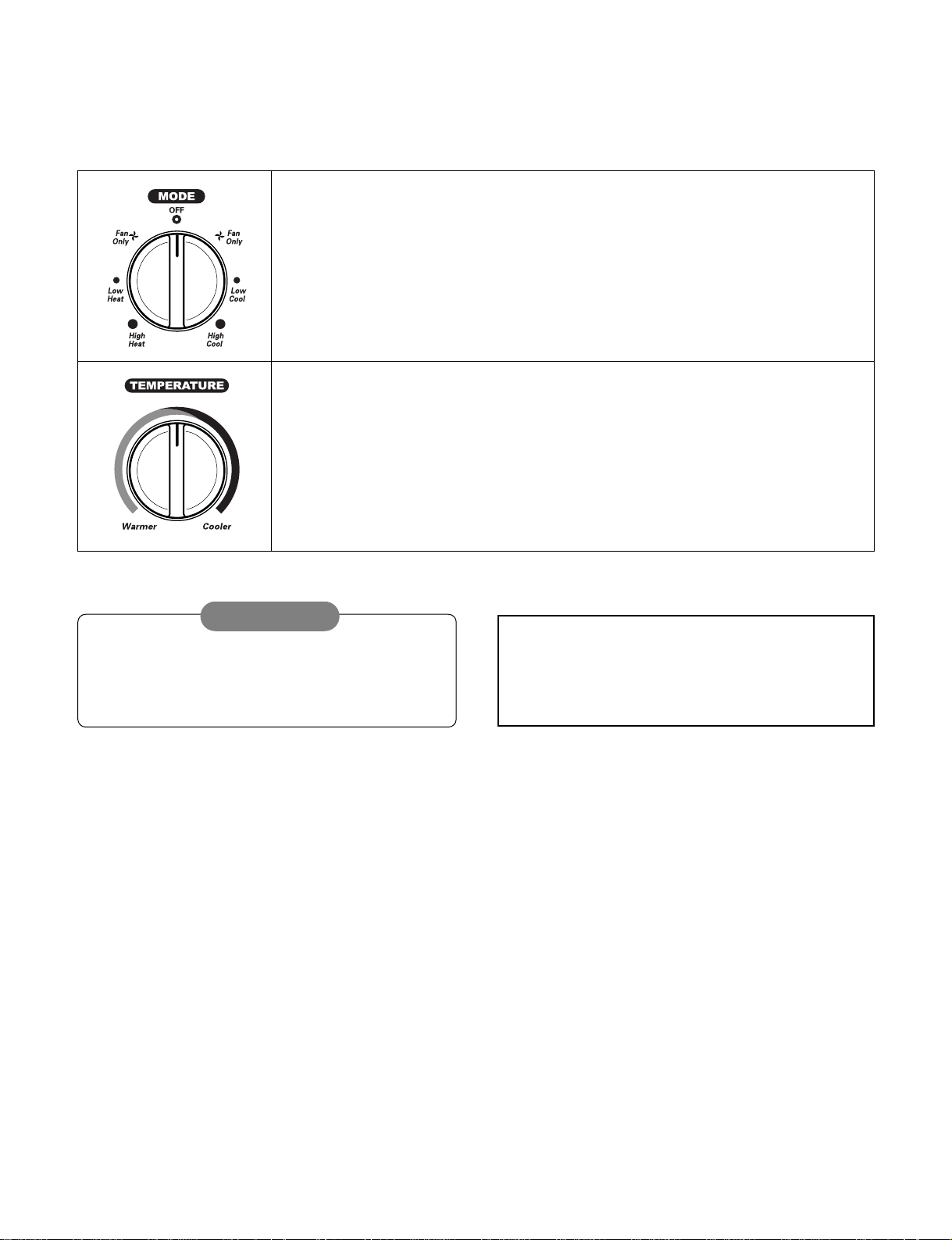
1.5.2 COOLING AND HEATING MODEL
• OPERATION
—7—
A slight burning odor may come from the unit
when first switching to HEAT after the cooling
season is over. This odor, caused by fine dust
particles on the heater, will disappear quickly.
This is normal operation.
Off - Turns the air conditioner off.
Fan Only - The low fan speed operation without cooling (heating).
Low Cool - Cooling with the low speed fan operation.
High Cool - Cooling with the high speed fan operation.
Low Heat - Heating with the low speed fan operation.
High Heat - Heating with the high speed fan operation.
Turn the Temperature Knob to the desired setting. The central position is a normal
setting for average conditions. You can change this setting, if necessary, in
accordance with your temperature preference.
The thermostat automatically controls cooling or heating, but the fan runs
continuously whenever the air conditioner is in operation. If the room is too warm,
turn the thermostat control clockwise. If the room is too cool, turn the thermostat
control counterclockwise.
When the air conditioner has been operated in the
cooling or heating mode and is turned off or set to the fan
position, wait at least 3 minutes before resetting to the
cooling operation again.
CAUTION
—8—
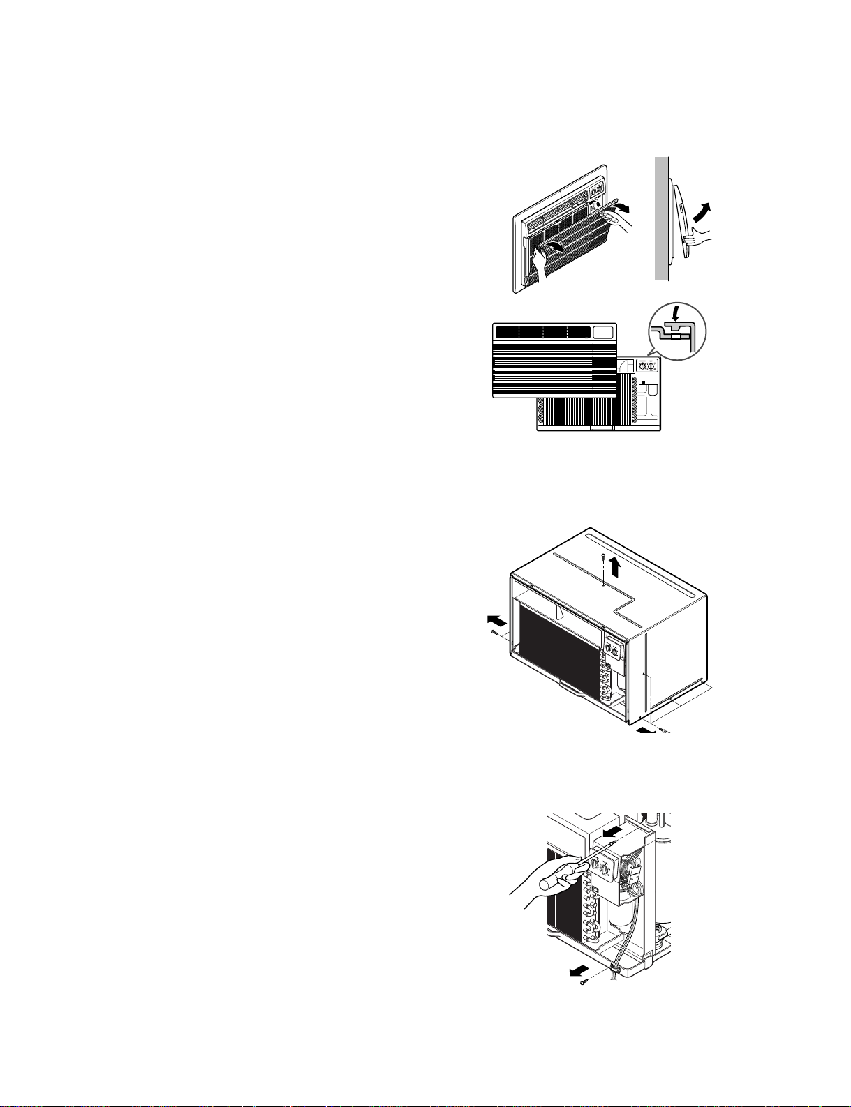
2.1 MECHANICAL PARTS
2.1.1 FRONT GRILLE
1. Open the inlet grille upward or downward.
2. Remove the screw which fastens the front grille.
3. Pull the front grille from the right side.
4. Remove the front grille. (See Fig. 1)
5. Re-install the component by referring to the
removal procedure.
2.1.2 CABINET
1. After disassembling the FRONT GRILLE, remove
the 9 screws which fasten the cabinet at the both
sides and the top. (See Fig. 2)
Keep these for later use.
2.1.3 CONTROL BOX
1. Remove the front grille. (Refer to section 2.1.1)
2. Remove the screw which fasten the control
box. (See Fig. 3)
3. Pull the control box from the barrier.(See Fig.3)
4. Discharge the capacitor by placing a 20,000 ohm
resistor across the capacitor terminals.
5. Disconnect two wire housings in the control box.
6. Pull the control box forward completely.
7. Re-install the components by referring to the
removal procedure. (See Fig. 3)
(Refer to the circuit diagram found on pages
26~27 in this manual and on the control box.)
2. DISASSEMBLY INSTRUCTIONS
— Before the following disassembly, POWER SWITCH is set to OFF and disconnected the power cord.
Figure 1
Figure 2
Figure 3
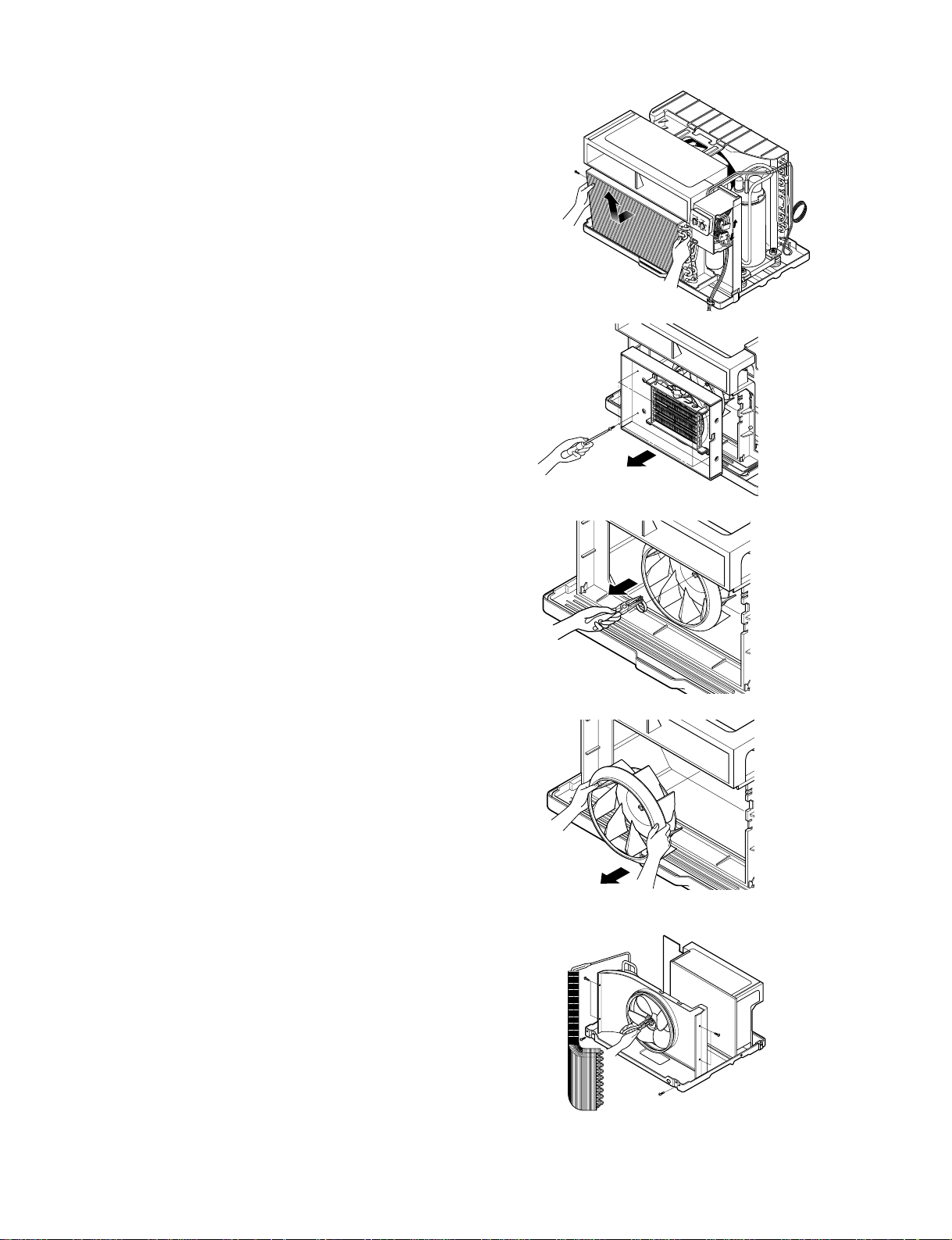
Figure 7
—9—
2.2 AIR HANDLING PARTS
2.2.1 ORIFICE, HEATER ASSY AND
TURBO FAN
1. Remove the front grille. (Refer to section 2.1.1)
2. Remove the cabinet. (Refer to section 2.1.2)
3. Remove the 2 screws which fasten the
evaporator at the left side and the right side.
(See Fig. 4)
4. Move the evaporator sideward carefully.
5. Remove the 2 terminals carefully
(See Fig. 5, at Electric Heater Model only)
6. Remove the 4 screws which fasten the orifice.
(See Fig. 5)
7. Remove the orifice. (See Fig. 5)
8. Remove the clamp which secures the turbo fan
with plier. (See Fig. 6)
9. Remove the turbo fan with plier or your hand
without touching blades. (See Fig. 7)
10. Re-install the components by referring to the
removal procedure, above.
2.2.2 FAN
1. Remove the cabinet. (Refer to section 2.1.2)
2. Remove the brace and shroud cover.
(Refer to section 2.2.1)
3. Remove the 6 screws which fasten the condenser.
4. Move the condenser sideways carefully.
5. Remove the clamp which secures the fan.
6. Remove the fan. (See Fig. 8)
7. Re-install the components by referring to the
removal procedure, above.
Figure 4
Figure 5
Figure 6
Figure 8
—10—
2.2.3 SHROUD
1. Remove the fan. (Refer to section 2.2.2)
2. Remove the screw which fasten the shroud.
3. Remove the shroud. (See Fig. 9)
4. Re-install the component by referring to the
removal procedure, above.
2.3 ELECTRICAL PARTS
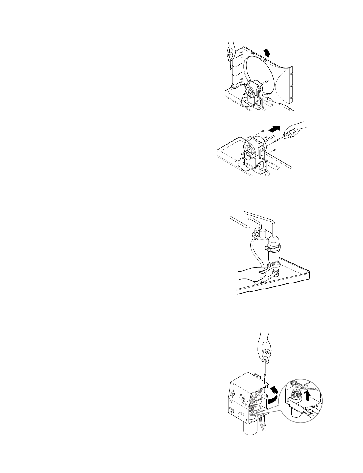
2.3.1 MOTOR
1. Remove the cabinet. (Refer to section 2.1.2)
2. Remove the clamp cord and disconnect a wire
housing in control box. (Refer to section 2.1.3)
3. Remove the turbo fan. (Refer to section 2.2.2)
4. Remove the fan. (Refer to section 2.2.2)
5. Remove the 4 or 2 screws which fasten the motor.
(See Fig. 10)
6. Remove the motor.
7. Re-install the components by referring to the
removal procedure, above.
2.3.2 COMPRESSOR
1. Remove the cabinet. (Refer to section 2.1.2)
2. Discharge the refrigerant system using Freon
TM
Recovery System.
If there is no valve to attach the recovery system,
install one (such as a WATCO A-1) before venting
the Freon
TM
. Leave the valve in place after
servicing the system.
3. Disconnect the 3 leads from the compressor.
4. After purging the unit completely, unbraze the
suction and discharge tubes at the compressor
connections.
5. Remove the 3 nuts and the 3 washers which
fasten the compressor. (See Fig. 11)
6. Remove the compressor.
7. Re-instill the components by referring to the
removal procedure, above.
2.3.3 CAPACITOR
1. Remove the control box. (Refer to section 2.1.3)
2. Remove knobs and the tips which fasten the
display panel.
3. Disconnect the 2 leads from the rocker switch and
remove the panel (Energy saver model only).
4. Remove 2 screws and unfold the control box.
(See Fig. 12)
5. Remove the Rotary Switch.
6. Remove the screw and the clamp which fastens
the capacitor. (See Fig. 12)
7. Disconnect all the leads of capacitor terminals.
8. Re-install the components by referring to the
removal procedure, above.
Figure 9
Figure 10
Figure 11
Figure 12
—11—
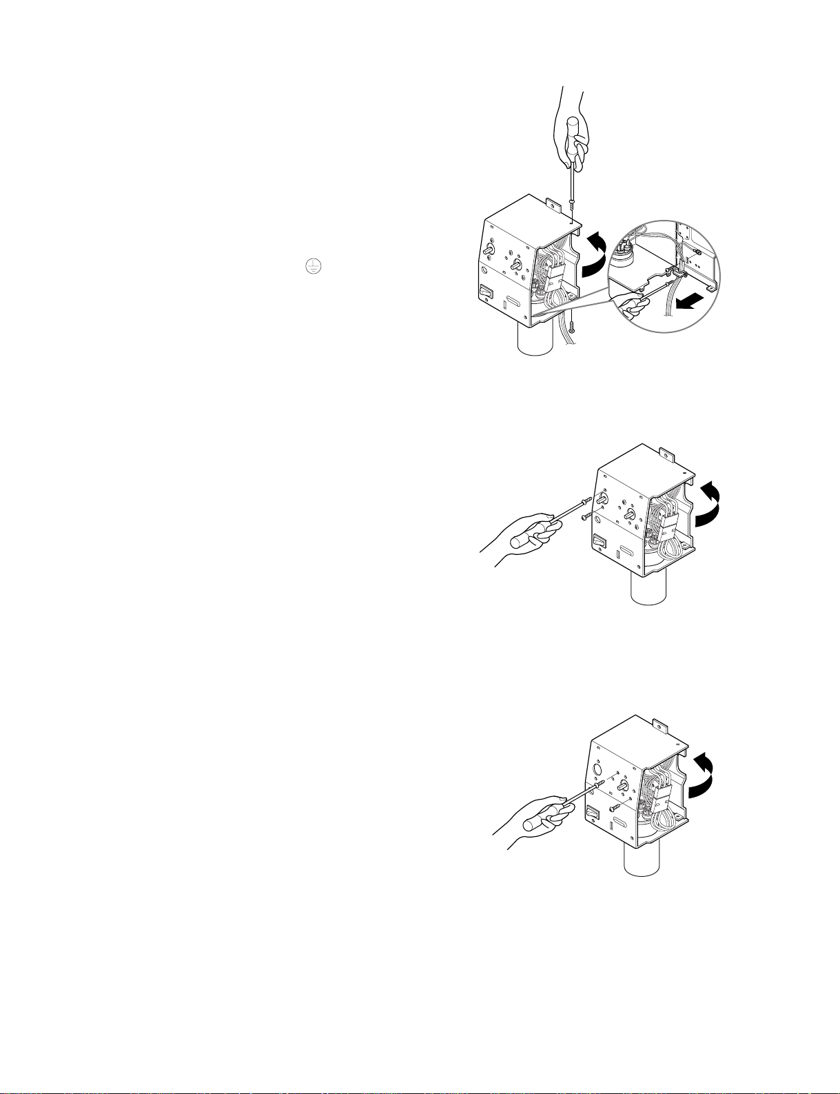
2.3.4 POWER CORD
1. Remove the control box. (Refer to section 2.1.3)
2. Unfold the control box. (Refer to section 2.3.3)
3. Disconnect the grounding screw from the control
box.
4. Disconnect 2 receptacles.
5. Remove a screw which fastens the clip cord.
6. Pull the power cord. (See Fig. 13)
7. Re-install the component by referring to the
removal procedure, above.
(Use only one ground-marked hole for ground
connection.)
8. If the supply cord of this appliance is damaged, it
must be replaced by the special cord.
(The special cord means the cord which has the
same specification marked on the supply cord
fitted to the unit.)
2.3.5 THERMOSTAT
1. Remove the control box. (Refer to section 2.1.3)
2. Unfold the control box. (Refer to section 2.3.3)
3. Remove the 2 screws which fasten the thermostat.
4. Disconnect all the leads of thermostat terminals.
5. Remove the thermostat. (See Fig. 14)
6. Re-install the components by referring to the
removal procedure, above.
2.3.6 ROTARY SWITCH
1. Remove the control box. (Refer to section 2.1.3)
2. Unfold the control box. (Refer to section 2.3.3)
3. Remove 2 screws which fasten the rotary switch.
4. Disconnect all the leads of the rotary switch
terminals.
5. Remove the rotary switch. (See Fig. 15)
6. Re-install the components by referring to the
above removal procedure, above.
Figure 13
Figure 14
Figure 15
 Loading...