


Friedrich EM24, YS10, YS12, YM18, ES16 User Manual
...Installation and Operation Manual
Room Air Conditioners
Standard Chassis Models
115-Volt: SS08, SS10, SS12, SS14, SM15 208-230-Volt: SS12, SS16, SM18, SM21, SM24
SL22, SL24, SL28, SL36
115-Volt: YS10
208-230-Volt: ES12, ES16, YS12, EM18
YM18, EM24, EL36, YL24
93001010_00
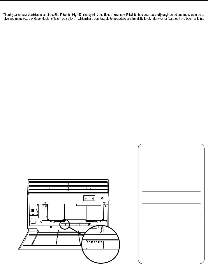
your unit to assure quiet operation, the greatest circulation of cool, dry air, and the most economic operation.
THANK YOU, on behalf of our entire company, for making such a wise purchase.
UL |
|
MODEL NUMBER |
CONDITIONING . |
YS10N10 |
SAN ANTONIO, TEXAS |
SERIAL NUMBER |
ASSEMBLED IN MEXICO |
LICY00008 |
Register your air conditioner
Model information can be found on the name plate behind the front cover.
Please complete and mail the owner registration card furnished with this product, or register online at www.friedrich.com.
For your future convenience, record the model information here.
MODEL NUMBER
SERIAL NUMBER
PURCHASE DATE
2

|
Table of Contents |
Safety Precautions................................................................................................................................................................................................................... |
4 |
Unpacking Instructions............................................................................................................................................................................................................. |
5 |
WARNING: Before Operating Your Unit .................................................................................................................................................................................. |
6 |
Standard Filter Cleaning / Installation Instructions .................................................................................................................................................................. |
7 |
Premium Carbon Filter Installation Instructions....................................................................................................................................................................... |
8 |
Control Panel Operation ......................................................................................................................................................................................................... |
9 |
New Kühl Control Options ...................................................................................................................................................................................................... |
10 |
Control Panel Operation Instructions ................................................................................................................................................................. |
.................. 11 |
Remote Control Operation ..................................................................................................................................................................................................... |
20 |
Remote Effectiveness ............................................................................................................................................................................................................ |
20 |
.......................................................................................................................................................................................... |
22 |
Installation Instructions .......................................................................................................................................................................................................... |
23 |
Standard Window Installation ................................................................................................................................................................................................ |
25 |
Cord Routing Change ............................................................................................................................................................................................................ |
34 |
Through-the-Wall Installation................................................................................................................................................................................................. |
36 |
Final Inspection & Start-up Checklist..................................................................................................................................................................................... |
40 |
Routine Maintenance ............................................................................................................................................................................................................. |
41 |
Service and Assistance ......................................................................................................................................................................................................... |
41 |
Available Accessories ............................................................................................................................................................................................................ |
41 |
Troubleshooting Tips.............................................................................................................................................................................................................. |
42 |
Addendum 1 ........................................................................................................................................................................................................................... |
44 |
Warranty ................................................................................................................................................................................................................................ |
45 |
3
Safety Precautions
Your safety and the safety of others are very important.
We have provided many important safety messages in this manual and on your appliance. Always read and obey all safety messages.
This is a safety Alert symbol.
This symbol alerts you to potential hazards that can kill or hurt you and others. All safety messages will follow the safety alert symbol with the word “WARNING” or “CAUTION”. These words mean:
 WARNING
 CAUTION
Indicates a hazard which, if not avoided, can result in severe personal injury or death and damage to product or other property.
Indicates a hazard which, if not avoided, can result in personal injury and damage to product or other property.
All safety messages will tell you what the potential hazard is, tell you how to reduce the chance of injury, and tell you what will happen if the instructions are not followed.
NOTICE
Indicates property damage can occur if instructions are not followed.
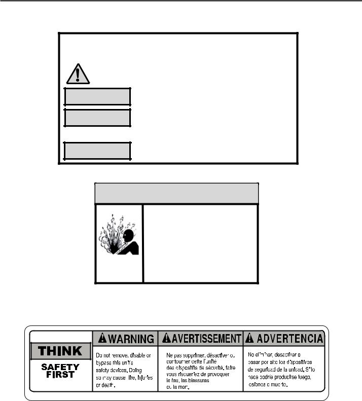
 WARNING
Refrigeration system under high pressure
Do not puncture, heat, expose to flame or incinerate.
Only certified refrigeration technicians should service this equipment.
R410A systems operate at higher pressures than R22 equipment. Appropriate safe service and handling practices must be used.
Only use gauge sets designed for use with R410A. Do not use standard R22 gauge sets.
4

Unpacking Instructions |
STEP 5. |
Slide the foam front support forward |
|
STEP 1. |
Cut all 4 packing straps. |
STEP 6. |
Carefully lift decorative front box from foam front support |
STEP 2. |
Remove wooden shipping bar dividers. |
STEP 7. |
Remove decorative front and set safely aside |
STEP 3. |
Remove top foam pads. |
|
|
STEP 4. |
Slowly remove outer box, careful not to loosen decorative front. |
|
|
5
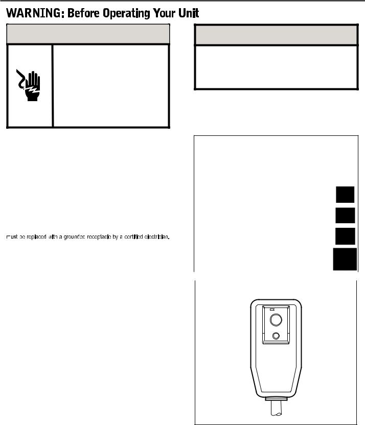
 WARNING
Electrical Shock Hazard
Make sure your electrical receptacle has the same configuration as your air conditioner’s plug. If different, consult a Licensed Electrician.
Do not use plug adapters. Do not use an extension cord. Do not remove ground prong.
Always plug into a grounded 3 prong oulet. Failure to follow these instructions can result in death, fire, or electrical shock.
Make sure the wiring is adequate for your unit.
If you have fuses, they should be of the time delay type. Before you install or relocate this unit, be sure that the amperage rating of the circuit breaker or time delay fuse does not exceed the amp rating listed in Table 1.
DO NOT use an extension cord.
The cord provided will carry the proper amount of electrical power to the unit; an extension cord may not.
Make sure that the receptacle is compatible with the air conditioner cord plug provided.
Proper grounding must be maintained at all times. Two prong receptacles
The grounded receptacle should meet all national and local codes and ordinances. You must use the three prong plug furnished with the air conditioner. Under no circumstances should you remove the ground prong from the plug.
Test the power cord
All Friedrich room air conditioners are shipped from the factory with a Leakage Current Detection Interrupter (LCDI) equipped power cord. The LCDI device on the end of the cord meets the UL and NEC requirements for cord connected air conditioners.
To test your power supply cord:
1.Plug power supply cord into a grounded 3 prong outlet.
2.Press RESET (See Figure 1).
3.Press TEST, listen for click; the RESET button trips and pops out.
4.Press and release RESET (Listen for click; RESET button latches and remains in). The power cord is ready for use.
NOTICE
Do not use the LCDI device as an ON/OFF switch.
Failure to adhere to this precaution may cause premature equipment malfunction.
Once plugged in, the unit will operate normally without the need to reset the LCDI device. If the LCDI device fails to trip when tested or if the power supply cord is damaged, it must be replaced with a new power supply cord from the manufacturer. Contact our Technical Assistance Line at (800) 541-6645. To expedite service, please have your model number available.
Table 1.
|
|
CIRCUIT RATING |
REQUIRED |
|||
|
|
OR TIME DELAY |
WALL |
|||
|
MODEL |
FUSE |
RECEPTACLE |
|||
|
|
AMP |
VOLT |
NEMA |
|
|
|
|
NO. |
|
|
||
|
|
|
|
|
|
|
|
SS08, SS10 |
|
|
|
|
|
|
SS12, SS14 |
15 |
125 |
5-15R |
|
|
|
YS10, SM15 |
|
|
|
|
|
|
SS12, SS16 |
15 |
250 |
6-15R |
|
|
|
SM18, SM21 |
|
|
|||
|
SL22 |
|
|
|
|
|
|
SM24, SL28 |
|
|
|
|
|
|
ES12, ES16 |
20 |
250 |
6-20R |
|
|
|
YS12, SL24 |
|
|
|
|
|
|
SL36, EM18 |
|
|
|
|
|
|
EM24, EL36 |
30 |
250 |
6-30R |
|
|
|
YM18, YL24 |
|
|
|
|
|
|
|
|
|
|
|
|
|
|
|
|
|
|
|
|
Figure 1 |
|
|
|
|
|
RESET
TEST
WARNING:
TEST BEFORE EACH USE!
1.PRESS REST BUTTON.
2.PLUG LCDI INTO POWER RECEPTACLE.
3.PRESS TEST BUTTON, RESET BUTTON SHOULD POP UP.
4.PRESS RESET BUTTON FOR USE.
DO NOT USE IF ABOVE TEST
FAILS.
WHEN GREEN LIGHT IS ON.
IT IS WORKING
PROPERLY!
FRR072
6
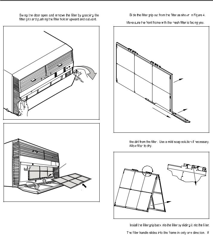
Standard Filter Cleaning / Installation Instructions
STEP 1.
FIGURE 2 |
FRR071 |
FIGURE 3 |
FILTER
GRIP
HANDLE
FRR052
STEP 2. |
NOTE: |
FIGURE 4 |
FILTER |
FILTER |
GRIP |
FRR047 |
STEP 3. Swing the front frame open. Clean the front frame by washing
FIGURE 5 |
A |
TOP TAB |
FRONT |
FRAME WITH |
STANDARD |
MESH FILTER |
FRR048 |
STEP 4. |
NOTE: |
the tab in the frame stops the handle from sliding in, slide the handle from the other direction. DO NOT FORCE THE HANDLE INTO
THE FRAME.
STEP 5.  the inside of the front door.
7
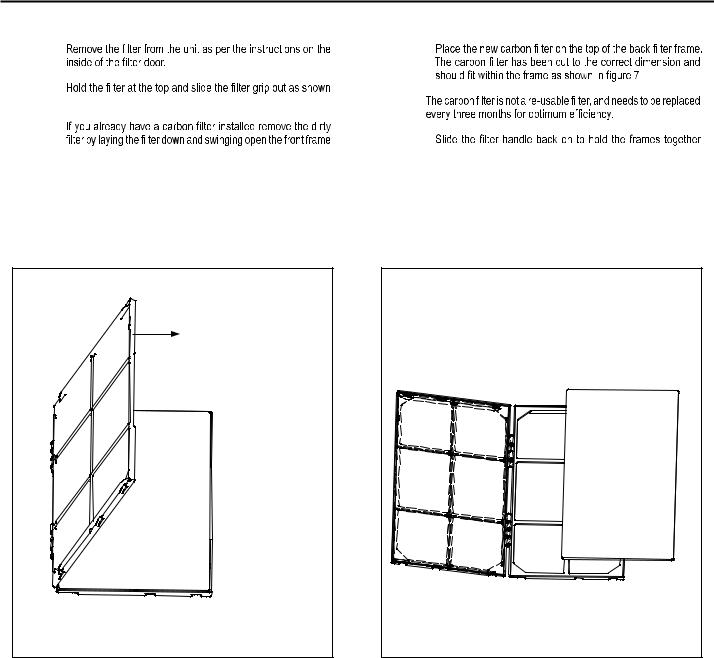
PREMIUM CARBON FILTER INSTALLATION INSTRUCTIONS
STEP 1. |
STEP 4. |
STEP 2. |
|
in Figure 4. |
NOTE: |
STEP 3. |
|
|
STEP 5. |
as shown in Figure 6.
NOTE: Make sure the frame with the mesh is facing towards you.
and slide the assembly into the unit as per the instructions on the door.
NOTE:  the tab in the frame stops the handle from sliding in, slide the handle from the other direction. DO NOT FORCE THE HANDLE INTO
THE FRAME.
FIGURE 6 |
FIGURE 7 |
FRONT FRAME WITH |
|
MESH FILTER |
|
FRR050 |
FRR051 |
8
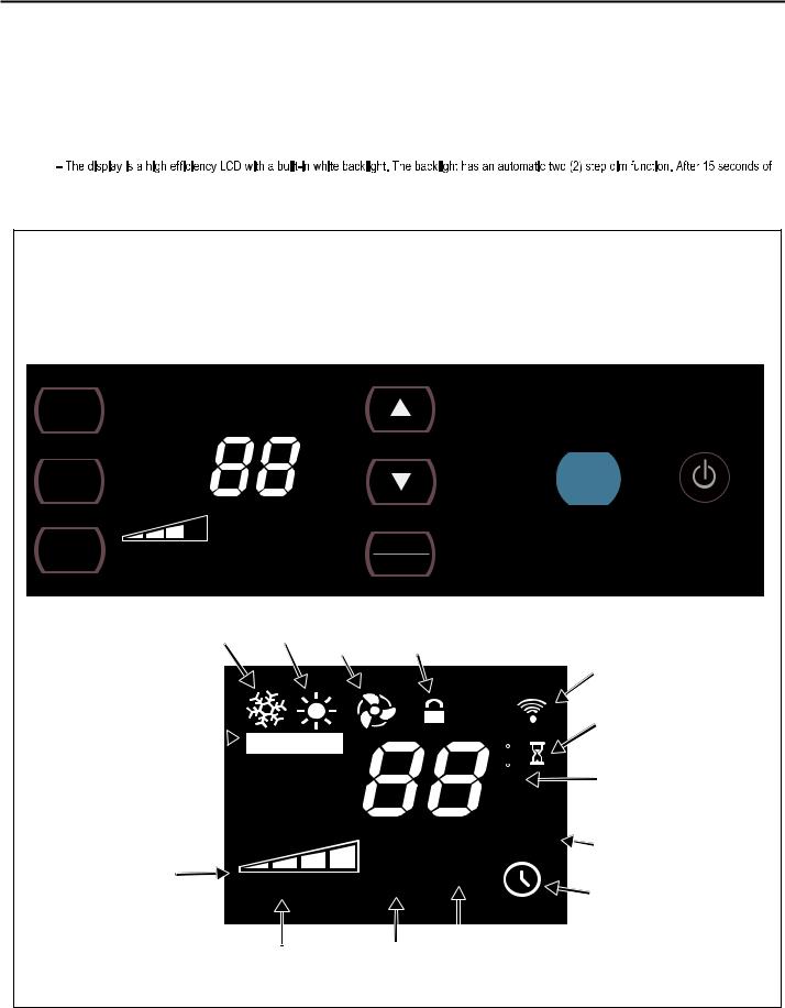
ControlPanelOperation
Let’s check out how to control your air conditioner. On the control panel, just above the POWER , is a liquid crystal display (LCD). All of the control panel function buttons and mode icons can be viewed in Figure 8.
Power On – Press the button to turn on the air conditioner. The power button illuminates to indicate that the power is on. The backlight on the power switch will automatically dim to 20% intensity after 15 seconds of inactivity. The remote control can also be used to turn power ON / OFF (See Remote Control).
Display
inactivity, the display dims to 20% intensity. After an additional 120 seconds, the display switches off. Touching any button automatically changes the display to full brightness.
There are three control push buttons on each side of the display.
Figure 8 |
|
SYSTEM |
FAN MODE |
Cycles between |
Sets fan to either: |
AUTO, HEAT, |
- Cycle automatically |
COOL, or FAN |
- Run continuously |
ONLY |
|
(if equipped) |
|
FAN SPEED |
TEMPERATURE |
TIMER / SCHEDULE |
|
Sets fan speed: |
Increment UP |
Turns ON or OFF |
|
LOW, MED, |
TEMPERATURE: |
IR WINDOW: |
ON / OFF |
HIGH or AUTO |
|||
(if equipped) |
Increment DOWN |
Do not block |
Turns unit on/off |
|
|
|
 F
F
SET POINT
AUTO SPEED
COOL HEAT FAN
ONLY
AUTO
Automatically switches between cool & heat
AUTO FAN
CONTINUOUS
FAN SPEED
Selected fan speed |
AUTO SPEED |
AUTO SPEED
Automatically selects best fan
cooling speed
CONTROL
LOCKED
|
|
|
|
|
|
WI-FI |
|
|
|
|
|
|
|
OPERATING |
|
|
|
|
|
|
|
(if equipped) |
|
|
|
|
|
|
|
WAIT |
|
|
|
|
F |
|
2 DIGIT DISPLAY |
||
|
|
|
C |
|
|
Shows Setting for: |
|
|
|
|
AM |
|
- Set Point (Temperature) |
||
|
|
|
|
- Room Temperature |
|||
|
|
|
PM |
|
|||
|
|
|
ON OFF |
|
- Clock (AM/PM) |
||
SET POINT |
|
|
|||||
SCHEDULE |
|
SCHEDULE ON |
|||||
ROOM TEMP |
|
|
|
|
|||
CHECK $MART |
|
|
|
|
|
||
FILTER |
|
|
|
|
|
TIMER ON |
|
|
|
|
|
|
|||
FILTER |
|
MART OPERATING |
|
|
|||
$ |
|
|
|||||
Check / Clean |
(if equipped) |
|
|
||||
9
NewKühlControlOptions
The new Kühl gives you a variety of options for control, programming, and scheduling including wireless capabilities
Wireless Programming and Control:
. The new FriedrichLink™ Adapter (sold seperately) allows you to conviently control, program and monitor your air conditioning unit remotely from a smartphone or computer.
FriedrichLink™ Adapter accessory available through Friedrich authorized retailers or www.friedrich.com. See FriedrichLink™ Adapter section on www.friedrich.com for complete details.
Pre-Programmed Scheduling Options:
Your unit’s digital control comes equipped with a 24-hour timer and two preprogrammed 7-day energy management options.
24-Hour Timer
The 24-hour timer allows you to turn the unit off and on at pre-set times by setting an on and off time on the unit control panel. (See page 12 for details on timer set-up.)
Pre-programmed Energy Management
Your unit comes from the factory with two (2) Pre-programmed Energy Management settings are shown in Addendum 1 (Residential & Commercial Schedule Table).
Energy Management Schedule Options are:
1.Residential Schedule – 40 Hr. Work Week
2.Commercial Schedule – 5-Day Business Week
The “Residential” (40 Hr. Work Week) Schedule has four (4) time periods: 06:00, 08:00, 18:00, and 22:00. This option will cause your Kühl Q unit to raise the room temperature temporarily to 85°F during the hours when most people are away at work, lower them again to 78°F prior to the time when most people will return home, and then raise slightly to 82°F to maintain a comfortable temperature overnight.
The “Commercial” (5-Day Business Week) Schedule has two (2) time periods: 07:00 and 18:00. This option will cause your air conditioner to raise temperatures to 84°F after typical working hours and on weekends when commercial spaces are typically unoccupied.
(See Control Panel Operation Instructions Section)
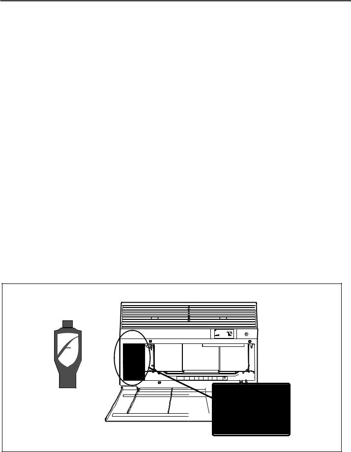
Customizable Programming Options:
Customizable schedules, with up to four temperature adjustments per day, can either be uploaded to the unit via the air conditioner’s built-in micro USB interface or conveniently transmitted wirelessly using the new FriedrichLink™ Adapter accessory, greatly simplifying the programming of one or multiple units.
See Figure 9.
See www.friedrich.com for complete details on
FriedrichLink.
Figure 9
UL |
FriedrichLink™ Adapter
10
Control Panel Operation Instructions
SYSTEM - The SYSTEM button allows you to sequentially select up to four modes of operation:
AUTO - AUTO - Not available on some models
COOL
HEAT  Not available on some models
FAN ONLY 
AUTO MODE
- AUTO - |
F |
|
AUTO FAN
SET POINT
FRR204
COOL MODE
F
AUTO FAN
SET POINT
FRR103
HEAT MODE
F
AUTO FAN
SET POINT
FRR104
FAN ONLY MODE
FRR105
When in the - AUTO-, COOL  or HEAT
 or FAN ONLY
 mode, you can also select FAN MODE, FAN SPEED, TIMER SCHEDULE,
 and
and  . The SYSTEM MODE does not change.
FAN MODE – The |
|
button allows you to select between AUTO FAN and |
|||
MODE |
|||||
|
modes. |
FAN |
|
|
|
|
|
|
|
|
|
CONTINUOUS |
|
|
|
|
|
AUTO FAN (No Cooling Demand)
F
AUTO FAN
SET POINT
FRR112
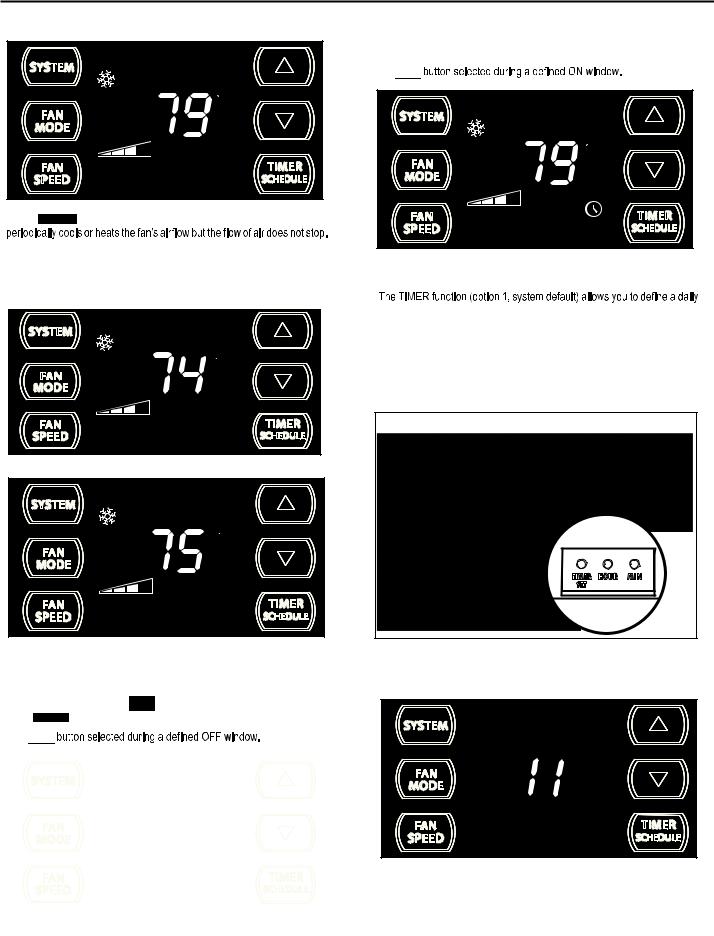
When in the AUTO FAN mode, the fan only operates when the system has a demand to cool or heat the room. Note: the fan is off (no fan speed icon), indicating no command for cooling or heating.
AUTO FAN (Cooling Demand)
F
AUTO FAN
SET POINT
FRR106
System has a demand for cooling. The fan is operating at a medium speed.
N |
|
|
FAN SPEED - Depending on your model, the |
|
button allows you to toggle between four or five modes of operation: LOW, MEDIUM, HIGH and AUTO. |
SPEED |
||
|
FAN |
|
4 Speed |
3 Speed |
AUTO |
AUTO |
When fan speed AUTO FAN mode (SYSTEM mode AUTO, COOL or HEAT) is selected, fan speed automatically varies depending on the difference between the unit’s set point on the control panel and the actual room temperature. When the system detects a wide difference between the set point and the actual room temperature the fan speed increases to HIGH for a period of time. The fan speed decreases, in step, as the temperature difference decreases. When the room temperature matches the system's set point, fan speed returns to the original setting.
11
CONTINUOUS
F
CONTINUOUS
SET POINT
FRR113
In the CONTINUOUS fan mode, the fan operates all the time. The system
UP  and DOWN
  - arrows - Pressing either
  or
or  button changes the system's set point (desired room temperature). These buttons are also used to make system parameter changes later in this manual.
F
AUTO FAN
SET POINT
FRR100
F
AUTO FAN
SET POINT
FRR101
One press equals 1 degree of change. Holding the button down for more than 0.6 seconds starts the fast increment/decrement change of the set point.
TIMER SCHEDULE - The  button allows you to select the TIMER
  or SCHEDULE function.
The 
|
|
|
|
|
|
|
|
The |
|
icon illuminates. |
FRR122 |
|
|||
|
|
The 
F
AUTO FAN
SET POINT
FRR123
The icon illuminates.
system ON and OFF time window. For example, you can command the system to turn ON at 8:15 am and turn OFF at 1:30 pm everyday.
The SCHEDULE function allows you to choose either Residential (option 2) or Commercial (option 3). The Residential and Commercial options are described later in this manual.
OTHER FUNCTIONS
Figure 10
SET TIME- To adjust the unit's time press and hold the HOUR and the MIN buttons for three seconds (Refer to Figure 10).
AM
FRR128
The unit's current hour displays. Use the  or
or  buttons to adjust the hour. To change from AM to PM continue to increment (roll) the display. Press TIMER SET (Refer to Figure 10) button to display the unit's current minutes.
12

To switch from degrees Fahrenheit (F) to Celsius (C), press  &
&  buttons for three seconds.
FRR129
Use the  or
or  buttons to adjust the minutes. The clock is now set for 11:25 AM. Press TIMER SET (Refer to Figure 10) button to display the unit's day setting.
FRR130
Use the  or
or  buttons to adjust the day (1 to 7). The day setting is up to you the user. If you set the current day = 1, and today is Tuesday, then Day 1 = Tuesday.
F
AUTO FAN
SET POINT
FRR131
Press TIMER SET (Refer to Figure 10) button to exit and save the SET TIME function. The TIMER SET button must be pressed within 15 second. Button inactivity for more than 15 seconds causes the display to time out and return to the normal operating display.
ºF - ºC Select
FRR133
from F to C, press the or
or button within 5 seconds.
FRR134
AUTO FAN |
C |
|
|
|
SET POINT |
FRR135
The ºF icon goes away and the ºC icon illuminates on the normal display.
DIM Function
There are three separate display brightness levels, AUTO, 20% and full (100%). To change the DIM setting, press the Power button for three seconds.
F
AUTO FAN
SET POINT
FRR132
FRR192
The 1 indicates a DIM setting of Auto (factory default). Use the  or
or  buttons to change the setting.
13
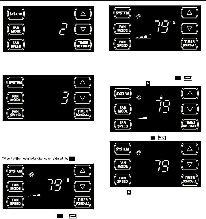
FRR193
The 2 indicates a DIM setting of 20%. Press the TIMER SET button within 15 seconds to save the setting. Button inactivity for more than 15 seconds causes the display to time out and return to the normal operating display.
FRR194
The 3 indicates a DIM setting of 100% (full brightness). Press the TIMER SET (Refer to Figure 10) button within 15 seconds to save the setting. Button inactivity for more than 15 seconds causes the display to time out and return to the normal operating display.
Alerts
CHECK icon displays.
FILTER
F
AUTO FAN
SET POINT
FILTER
The alert can be dismissed by pressing the |
|
and |
FRR118 |
MODE |
for 3 seconds. |
||
|
FAN |
|
|
The wait icon  illuminates when the compressor 3 minute time delay is active.
14
F
AUTO FAN
SET POINT
FRR120
This means there is a compressor demand but the system is not ready for the compressor to operate. For example a short power outage, the compressor will not restart until the internal pressures of the compressor are at the proper level.
Lock Control Panel |
|
|
|
buttons |
To lock the front panel controls, press and hold the SPEED + |
||||
|
|
|
FAN |
|
for 3 seconds. The lock icon |
illuminates to indicate the locked status. |
|||
AUTO FAN |
|
|
F |
|
|
|
|
|
|
|
|
SET POINT |
|
|
|
|
|
|
16 |
To unlock, presses and hold the |
|
+ |
|
FRR1 |
FAN |
buttons for 3 seconds. |
|||
|
SPEED |
|
|
|
|
F |
|
|
AUTO FAN |
|
|
SET POINT |
|
The lock icon |
disappears to indicate unlocked status. |
FRR117 |
|
 Loading...