


 Loading...
|
Contents |
Before driving |
|
|
|
Introduction |
2 |
|
|
|
|
Instrumentation |
8 |
|
|
|
|
Controls and features |
25 |
|
|
|
|
Seating and safety restraints |
72 |
|
|
Starting and driving |
|
|
|
Starting |
104 |
|
|
|
|
Driving |
109 |
|
|
|
|
Roadside emergencies |
145 |
|
|
Servicing |
|
|
|
Maintenance and care |
172 |
|
|
|
|
Capacities and specifications |
222 |
|
|
|
|
Customer assistance |
234 |
|
|
|
|
Reporting safety defects |
246 |
|
|
|
|
Index |
247 |
|
|
All rights reserved. Reproduction by any means, electronic or mechanical including photocopying, recording or by any information storage and retrieval system or translation in whole or part is not permitted without written authorization from Ford Motor Company. Ford may change the contents without notice and without incurring obligation.
Copyright © 1999 Ford Motor Company
1
Introduction
The following warning may be required by California law:
CALIFORNIA Proposition 65 Warning
Engine exhaust, some if its constituents, and certain vehicle components contain or emit chemicals known to the State of
California to cause cancer, or birth defects or other reproductive harm.
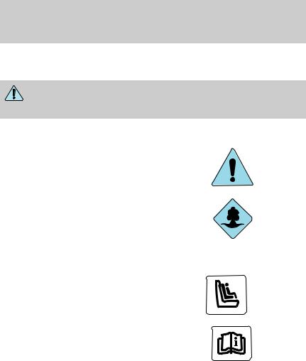
ICONS
Indicates a safety alert. Read the following section on Warnings.
Indicates vehicle information related to recycling and other environmental concerns will follow.
Correct vehicle usage and the authorized disposal of waste
cleaning and lubrication materials are significant steps towards protecting the environment.
Indicates a message regarding child safety restraints. Refer to Seating and safety restraints for more information.
Indicates that this Owner Guide contains information on this subject. Please refer to the Index to locate the appropriate section which will provide you more information.
2

Introduction
WARNINGS
Warnings provide information which may reduce the risk of personal injury and prevent possible damage to others, your vehicle and its equipment.
BREAKING-IN YOUR VEHICLE
There are no particular breaking-in rules for your vehicle. During the first 1 600 km (1 000 miles) of driving, vary speeds frequently. This is necessary to give the moving parts a chance to break in.
INFORMATION ABOUT THIS GUIDE
The information found in this guide was in effect at the time of printing. Ford may change the contents without notice and without incurring obligation.
SPECIAL NOTICES
Notice to owners of diesel-powered vehicles
Read the 7.3 Liter Power Stroke Direct Injection Turbo Diesel Owner’s Guide Supplement for information regarding correct operation and maintenance of your diesel-powered light truck.
Notice to owners of pickup trucks and utility type vehicles
Utility vehicles have a significantly higher rollover rate than other types of vehicles.
Before you drive your vehicle, please read this Owner’s Guide carefully. Your vehicle is not a passenger car. As with other vehicles of this type, failure to operate this vehicle correctly may result in loss of control or an accident.
Be sure to read Driving off road in the Driving chapter as well as the “Four Wheeling” supplement included with 4WD and utility type vehicles.
3

Introduction
Using your vehicle with a snowplow
For more information and guidelines for using your vehicle with a snowplow, refer to the Driving chapter.
Using your vehicle as an ambulance
If your light truck is equipped with the Ford Ambulance Preparation Package, it may be utilized as an ambulance. Ford urges ambulance manufacturers to follow the recommendations of the Ford Incomplete Vehicle Manual, Ford Truck Body Builder’s Layout Book and the QVM guidelines as well as pertinent supplements. For additional information, please contact the Truck Body Builders Advisory Service 1–877–840–4338.
Use of your Ford light truck as an ambulance, without the Ford Ambulance Preparation Package voids the Ford New Vehicle Limited Warranty and may void the Emissions Warranties. In addition, ambulance usage without the preparation package could cause high underbody temperatures, overpressurized fuel and a risk of spraying fuel which could lead to fires.
4
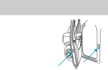
Introduction
If your vehicle is equipped with the Ford Ambulance Preparation Package, it will be indicated on the Certification label. The label is located on the driver’s side door pillar or on the rear edge of the driver’s door. You can determine whether the ambulance manufacturer followed Ford’s recommendations by directly contacting that manufacturer. Ford Ambulance Preparation Package is only available on certain 7.3L Diesel engine equipped vehicles.
Notice to owners with vehicles equipped with Power Take Off (PTO) capability
Refer to the Driving chapter for more information and guidelines for operating vehicles equipped with PTO.
5
Introduction
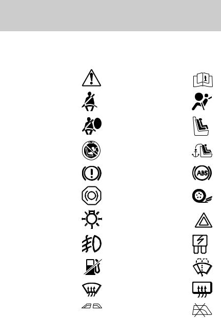
These are some of the symbols you may see on your vehicle.
Vehicle Symbol Glossary |
||
Safety Alert |
See Owner’s Guide |
|
Fasten Safety Belt |
Air Bag-Front |
|
Air Bag-Side |
Child Seat |
|
Child Seat Installation |
Child Seat Tether |
|
Warning |
Anchorage |
|
Brake System |
Anti-Lock Brake System |
|
Brake Fluid - |
Traction Control |
|
Non-Petroleum Based |
||
|
||
Master Lighting Switch |
Hazard Warning Flasher |
|
Fog Lamps-Front |
Fuse Compartment |
|
Fuel Pump Reset |
Windshield Wash/Wipe |
|
Windshield |
Rear Window |
|
Defrost/Demist |
Defrost/Demist |
|
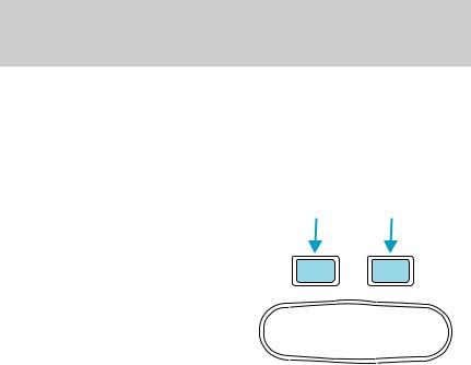
Power Windows
Power Window Lockout
Front/Rear
6
Introduction
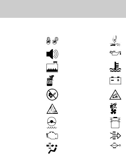
Vehicle Symbol Glossary
Child Safety Door
Interior Luggage
Lock/Unlock
Compartment Release
Symbol
Panic Alarm |
Engine Oil |
Engine Coolant
Engine Coolant
Temperature
Do Not Open When Hot |
Battery |
Avoid Smoking, Flames,
Battery Acid
or Sparks
Explosive Gas |
Fan Warning |
Power Steering Fluid
Maintain Correct Fluid
Level
Emission System |
Engine Air Filter |
|
Passenger Compartment |
Jack |
|
Air Filter |
||
|
MAX
MIN
7

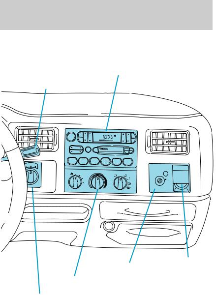
Instrumentation
Instrument cluster
(pg. 10)
Speed control* Turn signal and (pg. 56)
wiper/washer control (pg. 61)
- |
+ |
|
|
|
50 |
60 |
|
|
|
|
|
FUEL FILL |
|
40 |
70 |
|
3 |
|
|
|
|
LOW |
|
|
|
|
|
4 |
|
||
FUEL |
30 |
|
80 |
|
2 |
|
|
|
|
F |
|
100 |
|
|
|
||||
|
60 |
80 |
|
|
|
|
|||
|
|
120 |
|
|
|
|
|||
H |
|
|
|
|
|
|
|
|
|
E |
20 |
40 |
0 0 0 0 0 0 |
90 1 |
|
|
5 |
|
|
|
140 |
|
|
|
|||||
L |
|
|
|
|
|
|
|
||
H |
10 |
20 |
|
0 km/h 160 |
|
|
ABS |
|
CRUISE |
|
MPH 0 0 0 |
100 0 |
|
|
|
|
|||
18 |
|
RPM X1000 |
|
6 |
|
||||
C |
0 |
|
|
|
|
|
|
|
|
|
|
P R N D |
2 1 |
SERVICE |
LOW |
|
BRAKE |
|
|
8 |
|
|
ENGINE |
4 X 4 |
! |
DOOR |
|||
|
|
|
|
|
SOON |
RANGE |
AJAR |
||
P
PANEL
DIM
O
|
RES |
ON |
SET |
|
ACCEL |
OFF |
COAST |
Headlamp control (pg. 25)
Instrument panel |
|
|
dimmer switch |
Driver air bag |
|
(pg. 26) |
||
(pg. 88) |
||
|
* if equipped
8
Instrumentation
Electronic sound system (pg. 32)
Gearshift lever* (pg. 114)
VE |
|
RDRI |
|
OVE |
|
4X4 |
4X4 |
WD HIGH LOW |
|
VOL - PUSH ON
|
AM |
|
FM1 |
ST |
|
CLK |
|
BASS TREB |
|
|
|||
|
|
|
BAL |
FADE |
|
|
|
FM |
|
|
TAPE |
||
|
|
|
|
|
||
|
|
|
|
|
|
AMS |
|
SEEK |
|
|
|
|
|
|
SCAN |
EJ |
|
|
SIDE |
1 - 2 |
|
TUNE |
|
|
|
REW |
FF |
1 |
2 |
3 |
4 |
5 |
6 |
|
|
|
|
|
OFF |
|
|
PASSENGER AIR BAG
OFF
ON
OFF
Auxiliary
|
Passenger air bag |
power point |
|
deactivate switch |
|
|
(pg. 27) |
|
|
(pg. 92) |
|
Climate control system |
|
|
|
|
|
(pg. 27) |
|
|
4WD selector* |
|
|
(pg. 123) |
|
|
9
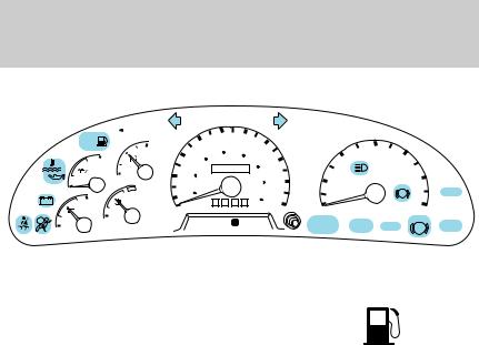
Instrumentation
WARNING LIGHTS AND CHIMES
- |
+ |
|
|
|
50 |
60 |
|
|
|
|
|
FUEL FILL |
|
40 |
70 |
|
3 |
|
|
|
|
LOW |
|
|
|
|
|
4 |
|
||
FUEL |
30 |
|
80 |
|
2 |
|
|
|
|
F |
|
100 |
|
|
|
||||
|
60 |
80 |
|
|
|
|
|||
H |
|
|
120 |
|
|
|
|
||
|
|
|
|
|
|
|
|
||
E |
20 |
40 |
0 0 0 0 0 0 |
90 1 |
|
|
5 |
|
|
|
140 |
|
|
|
|||||
L |
|
|
|
|
|
|
|
||
H |
10 |
20 |
|
0 km/h 160 |
|
|
ABS |
|
CRUISE |
|
MPH 0 0 0 |
100 0 |
|
|
|
|
|||
18 |
|
RPM X1000 |
|
6 |
|
||||
C |
0 |
|
|
|
|
|
|
|
|
|
|
P R N D |
2 1 |
SERVICE |
LOW |
|
BRAKE |
DOOR |
|
8 |
|
|
|
||||||
|
|
ENGINE |
4 X 4 |
! |
|||||
|
|
|
|
|
SOON |
RANGE |
|
AJAR |
|
Low fuel
Illuminates as an early reminder of a
low fuel condition indicated on the fuel gauge (refer to Fuel Gauge in
this chapter for more information). When refueling, after the light
comes on, the amount of fuel that is added will be less than the advertised capacity since there is fuel still in the tank. The ignition must be in the ON position for this lamp to illuminate. The lamp will also illuminate for several seconds after the ignition is turned to the ON position regardless of the fuel level to ensure your bulb is working.
Service engine soon
Your vehicle is equipped with a computer that monitors the engine’s emission control system. This system is commonly known as the On Board Diagnostics System (OBD II). The OBD II system protects the
environment by ensuring that your vehicle continues to meet government emission standards. The OBD II system also assists the service technician in properly servicing your vehicle.
The Service Engine Soon indicator light illuminates when the ignition is first turned to the ON position to check the bulb. If it comes on after the engine is started, one of the engine’s emission control systems may be malfunctioning. The light may illuminate without a driveability concern being noted. The vehicle will usually be drivable and will not require towing.
10
Instrumentation
What you should do if the Service Engine Soon light illuminates
Light turns on solid:
This means that the OBD II system has detected a malfunction.
Temporary malfunctions may cause your Service Engine Soon light to illuminate. Examples are:
1.The vehicle has run out of fuel. (The engine may misfire or run poorly.)
2.Poor fuel quality or water in the fuel.
3.The fuel cap may not have been properly installed and securely tightened.
These temporary malfunctions can be corrected by filling the fuel tank with high quality fuel of the recommended octane and/or properly installing and securely tightening the gas cap. After three driving cycles without these or any other temporary malfunctions present, the Service Engine Soon light should turn off. (A driving cycle consists of a cold engine startup followed by mixed city/highway driving.) No additional vehicle service is required.
If the Service Engine Soon light remains on, have your vehicle serviced at the first available opportunity.
Light is blinking:
Engine misfire is occurring which could damage your catalytic converter. You should drive in a moderate fashion (avoid heavy acceleration and deceleration) and have your vehicle serviced at the first available opportunity.
Under engine misfire conditions, excessive exhaust temperatures could damage the catalytic converter, the fuel system, interior
floor coverings or other vehicle components, possibly causing a fire.
Service engine soon (California only)
Your vehicle is equipped with a computer that monitors the engine’s emission control system. This system is commonly known as the On Board Diagnostics System (OBD II). This OBD II system protects the
environment by ensuring that your vehicle continues to meet
11

Instrumentation
government emission standards. The OBD II system also assists the service technician in properly servicing your vehicle.
The Service Engine Soon indicator light illuminates when the ignition is first turned to the ON position to check the bulb. If it comes on after the engine is started, one of the engine’s emission control systems may be malfunctioning. The light may illuminate without a driveability concern being noted. The vehicle will usually be drivable and will not require towing.
What you should do if the Service Engine Soon light illuminates
Light turns on solid:
This means that the OBD II system has detected a malfunction.
Temporary malfunctions may cause your Service Engine Soon light to illuminate. Examples are:
1.The vehicle has run out of fuel. (The engine may misfire or run poorly.)
2.Poor fuel quality or water in the fuel.
3.The fuel cap may not have been properly installed and securely tightened.
These temporary malfunctions can be corrected by filling the fuel tank with high quality fuel of the recommended octane and/or properly installing and securely tightening the gas cap. After three driving cycles without these or any other temporary malfunctions present, the Service Engine Soon light should turn off. (A driving cycle consists of a cold engine startup followed by mixed city/highway driving.) No additional vehicle service is required.
If the Service Engine Soon light remains on, have your vehicle serviced at the first available opportunity.
Light is blinking:
Engine misfire is occurring which could damage your catalytic converter. You should drive in a moderate fashion (avoid heavy acceleration and deceleration) and have your vehicle serviced at the first available opportunity.
Under engine misfire conditions, excessive exhaust temperatures could damage the catalytic converter, the fuel system, interior
floor coverings or other vehicle components, possibly causing a fire.
12
Instrumentation
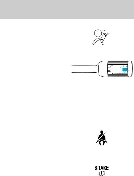
Air bag readiness
Momentarily illuminates when the ignition is turned ON. If the light fails to illuminate, continues to flash or remains on, have the system serviced immediately.
Transmission control indicator light (TCIL)
Illuminates when the Transmission
Control Switch (TCS), refer to
Overdrive control in the Controls OVERDRIVE 


 and Features chapter, has been
pushed turning the transmission
overdrive function OFF. When the TCIL (the word OFF on the gear shift) light is on, the transmission does not operate in the overdrive mode, refer to the Driving chapter for transmission function and operation.
The light may also flash steadily if a transmission malfunction is detected. If the light does not come on when the Transmission Control Switch is depressed or if the light flashes steadily, have your vehicle serviced as soon as possible, damage to the transmission could occur.
Safety belt
Momentarily illuminates when the ignition is turned to the ON position to remind you to fasten your safety belts. For more information, refer to the Seating and safety restraints chapter.
Brake system warning
Momentarily illuminates when the ignition is turned to the ON
position. Also illuminates if the parking brake is engaged. If the
brake warning lamp does not
illuminate at these times, seek service immediately. Illumination after releasing the parking brake indicates low brake fluid level and the brake system should be inspected immediately.
13

Instrumentation
Anti-lock brake system (ABS)
Momentarily illuminates when the
ignition is turned to the ON ABS position. If the light remains on,
continues to flash or fails to illuminate, have the system serviced
immediately. With the ABS light on, the anti-lock brake system is disabled and normal braking is still effective unless the brake warning light also remains illuminated with the parking brake released.
Turn signal
Illuminates when the left or right turn signal or the hazard lights are turned on. If one or both of the indicators stay on continuously or flash faster, check for a burned-out
turn signal bulb. Refer to Exterior bulbs in the Maintenance and care chapter.
High beams
Illuminates when the high beam headlamps are turned on.
Charging system
Illuminates when the ignition is turned to the ON position and the engine is off. The light also illuminates when the battery is not charging properly, requiring electrical system service.
Four wheel drive low (if equipped)
Momentarily illuminates when the ignition is turned to the START position. Illuminates when four-wheel drive low is engaged. If
the light continues to flash have the system serviced.
14

Instrumentation
Four wheel drive indicator (if equipped) |
|
|
Momentarily illuminates when the |
4x4 |
|
ignition is turned to the START |
||
|
position. Illuminates when 4x4 range
is engaged. If the light continues to flash have the system serviced.
Door ajar
Illuminates when the ignition is in the ON or START position and any door is open.
Oil pressure/Engine coolant
This light will illuminate when the ignition is in the ON position and the:
•engine coolant temperature is very high
•engine oil pressure is low
•engine is off
DOOR AJAR
The light serves as a notice that a system needs your attention and to check the engine coolant temperature gauge and the engine oil pressure gauge.
Refer to Engine coolant temperature gauge and Engine oil pressure gauge in this chapter for more information.
Speed control |
|
•Standard analog instrument cluster |
CRUISE |
This light comes on when either the COAST/SET or RES/ACCEL controls
are pressed. It turns off when the cruise cancel control is pressed, the brake is applied or the ignition is turned to the OFF position.
•Optional electronic instrument |
CRUISE |
cluster |
|
The “CRUISE” light comes on when |
|
the ON control is pressed. |
|
15
Instrumentation
The “SET” light comes on when either the COAST/SET or RES/ACCEL controls are pressed. The “SET” light turns off when the cruise cancel control is pressed or the brake is applied. Both the “CRUISE” and “SET” lights turn off when the OFF control is pressed or the ignition is turned to the OFF position.
Safety belt warning chime 
Sounds to remind you to fasten your safety belts.
For information on the safety belt warning chime, refer to the Seating and safety restraints chapter.
Supplemental restraint system (SRS) warning chime 

For information on the SRS warning chime, refer to the Seating and safety restraints chapter.
Key-in-ignition warning chime
Sounds when the ignition key is left in the ignition in the OFF/LOCK or ACC position and the driver’s door is opened.
Headlamps on warning chime
Sounds when the headlamps or parking lamps are on, the ignition in the OFF position (and the key is not in the ignition) and the driver’s door is opened.
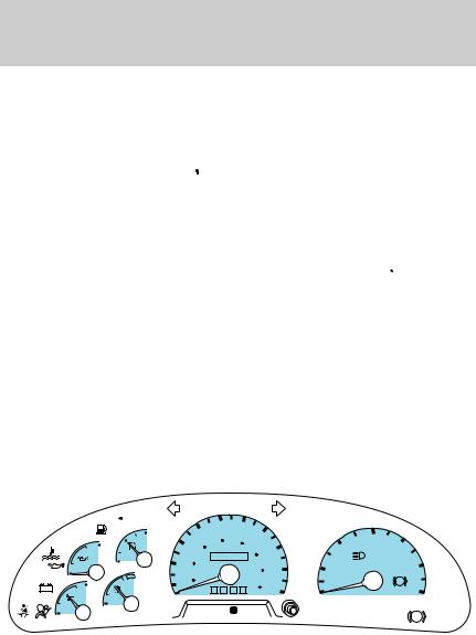
GAUGES
- |
+ |
|
|
|
50 |
60 |
|
|
|
|
|
FUEL FILL |
|
40 |
70 |
|
3 |
|
|
|
|
LOW |
|
|
|
|
|
4 |
|
||
FUEL |
30 |
|
80 |
|
2 |
|
|
|
|
F |
|
100 |
|
|
|
||||
|
60 |
80 |
|
|
|
|
|||
H |
|
|
120 |
|
|
|
|
||
|
|
|
|
|
|
|
|
||
E |
20 |
40 |
0 0 0 0 0 0 |
90 1 |
|
|
5 |
|
|
|
140 |
|
|
|
|||||
L |
|
|
|
|
|
|
|
||
H |
10 |
20 |
|
0 km/h 160 |
|
|
ABS |
|
CRUISE |
|
MPH 0 0 0 |
100 0 |
|
|
|
|
|||
18 |
|
RPM X1000 |
|
6 |
|
||||
C |
0 |
|
|
|
|
|
|
|
|
|
|
P R N D |
2 1 |
SERVICE |
|
|
BRAKE |
|
|
8 |
|
|
LOW |
|
DOOR |
||||
|
|
ENGINE |
4 X 4 |
! |
|||||
|
|
|
|
|
SOON |
RANGE |
|
AJAR |
|
16
Instrumentation
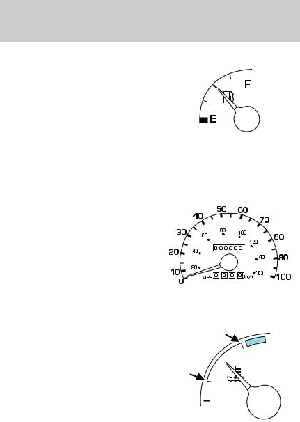
Fuel gauge
Displays approximately how much fuel is in the fuel tank (when the
key is in the ON position). The fuel gauge may vary slightly when the vehicle is in motion. The ignition should be in the OFF position while
the vehicle is being refueled. When the gauge first indicates empty, there is a small amount of reserve fuel in the tank. When refueling the
vehicle from an empty indication, the amount of fuel that can be added will be less than the advertised capacity due to the reserve fuel.
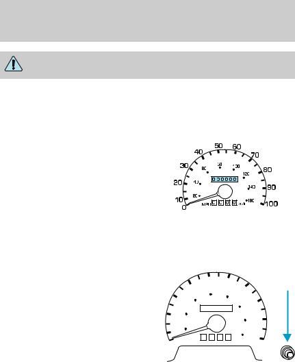
Speedometer
Indicates the current vehicle speed.
Engine coolant temperature gauge
Indicates the temperature of the engine coolant. At normal operating temperature, the needle remains within the normal area (the area between the “H” and “C”). If it enters the red section, the engine is overheating. Stop the vehicle as soon as safely possible, switch off the engine immediately and let the engine cool. Refer to Engine coolant in the Maintenance and care chapter.
H
C
17
Instrumentation
Never remove the coolant reservoir cap while the engine is running or hot.
This gauge indicates the temperature of the engine coolant, not the coolant level. If the coolant is not at its proper level the gauge indication will not be accurate.
Odometer
Registers the total kilometers (miles) of the vehicle.
Trip odometer |
|
|
|
|
Registers the kilometers (miles) of |
|
50 |
60 |
|
individual journeys. To reset, |
40 |
70 |
|
|
depress the control. |
|
|
|
|
|
80 |
|
|
|
30 |
|
100 |
80 |
|
|
60 |
|||
|
|
120 |
||
|
|
|
|
|
20 |
40 |
0 0 0 0 0 0 |
|
|
|
140 |
90 |
||
|
|
|
||
10 |
20 |
|
0 km/h 160 |
|
|
MPH 0 0 0 |
100 |
||
0 |
|
|
|
|
18
Instrumentation
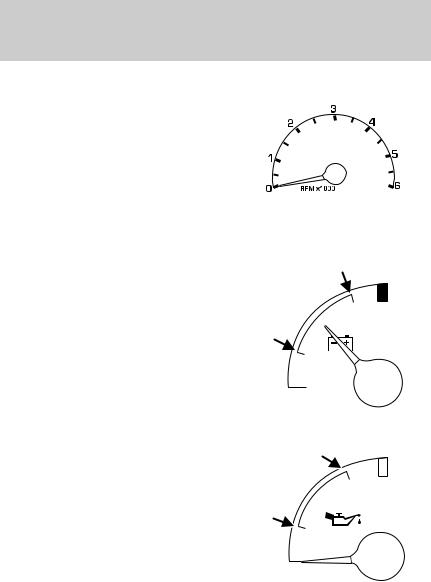
Tachometer
Indicates the engine speed in revolutions per minute.
Driving with your tachometer pointer at the top of the scale or in the red zone may damage the engine.
Battery voltage gauge |
|
This shows the battery voltage when |
|
the ignition is in the ON position. If |
|
the pointer moves and stays outside |
18 |
the normal operating range (as |
indicated), have the vehicle’s electrical system checked as soon as possible.
Engine oil pressure gauge
This shows the engine oil pressure in the system. Sufficient pressure exists as long as the needle remains in the normal range (the area between the “L” and “H”).

 8
8
H
If the gauge indicates low pressure, |
|
|
stop the vehicle as soon as safely |
|
L |
possible and switch off the engine |
|
|
|
||
immediately. Check the oil level. |
|
|
Add oil if needed (refer to Engine |
|
|
oil in the Maintenance and care |
|
|
chapter). If the oil level is correct, have your vehicle checked at your dealership or by a qualified technician.
19

Instrumentation
TRIP COMPUTER (IF EQUIPPED)
The trip computer tells you about the condition of your vehicle through a constant monitor of vehicle systems. You may select display features on the trip computer for a display of status.
The appearance of your vehicle’s trip computer may differ depending on your vehicle’s option package, but the functions are the same.
The trip computer only operates with the ignition in the ON position. Trip computer features follow:
Selectable features
English/metric display
Press this control to change the trip computer display between metric and English units.
MODE E/M
Mode control
Each press of the MODE control will display a different feature as follows:
Average fuel economy. The
display will indicate the vehicle’s MODE E/M average fuel economy in liters/100
km (or miles/gallon) since the average fuel economy was last reset.
If you calculate your average fuel economy by dividing liters of fuel used by 100 kilometers traveled
(miles traveled by gallons used), your figure may be different than displayed for the following reasons:
•your vehicle was not perfectly level during fill-up
•differences in the automatic shut-off points on the fuel pumps at service stations
20
Instrumentation
•variations in top-off procedure from one fill-up to another
•rounding of the displayed values to the nearest liter (gallon) To reset the average fuel economy:
1.Press the MODE control repeatedly until average fuel economy is displayed (this is the only resettable display).
2.Press the E/M and MODE
controls simultaneously. The display will illuminate the “AVG” indicator.
While the indicator is lit, release MODE E/M both controls to reset the average
fuel economy.
Fuel range. This displays the approximate number of kilometers (miles) left to drive before the fuel tank is empty. The indicated distance to empty may be inaccurate:
•with sustained, drastic changes in fuel economy (such as trailer towing), but will eventually recover.
•if the vehicle is started while parked on an incline.
•if less than 30 liters (8 gallons) of fuel is added to the fuel tank.
The fuel range function will flash for five seconds at the following distances based on fuel remaining and fuel economy calculations:
•80 km (50 miles)
•40 km (25 miles)
•16 km (10 miles)
21
Instrumentation
Outside air temperature
The temperature can be displayed in Centigrade or Fahrenheit by pressing the E/M control.
If the outside temperature falls |
MODE |
E/M |
|
|
|
below 3°C (38°F), the display will |
|
|
alternate from “ICE” to the outside |
|
|
temperature at a two second rate |
|
|
for one minute. |
|
|
Off. In this mode the display is off.
Compass
The compass display is contained in the overhead console. The vehicle heading is displayed as one of N, NE, E, SE, S, SW, W and NW.
The compass heading is displayed in average fuel economy modes, fuel range modes and temperature modes.
The compass reading may be affected when you drive near large buildings, bridges, power lines and powerful broadcast antenna. Magnetic or metallic objects placed in or on the vehicle may also affect compass accuracy. Adjustments may need to be made to the zone and calibration of the compass.
22

Compass zone adjustment
1. Determine which magnetic zone you are in for your geographic location by referring to the zone map.
Instrumentation
1
2. Locate the trip computer on the |
|
|
15 |
overhead console. |
2 |
|
|
|
14 |
||
3. Turn ignition to the ON position. |
3 |
|
13 |
|
4 |
|
|
|
|
12 |
|
|
|
|
|
|
5 |
|
11 |
|
|
|
|
|
6 |
|
10 |
|
7 |
8 |
9 |
4. Press and hold both trip computer controls. After approximately four seconds, the trip
computer will enter zone setting MODE E/M mode. Zone setting mode is
indicated when the display lights the “ZONE” indicator.
5.Release both controls. Subsequent pressing of either control will increment the zone.
Press the control repeatedly until the correct zone setting for your geographic location is displayed on the trip computer.
6.To exit the zone setting mode and save the displayed zone in memory, release both controls for greater than five seconds.
23
Instrumentation
Compass calibration adjustment
Perform this adjustment in an open area free from steel structures and high voltage lines.
For optimum calibration, turn off all electrical accessories (heater/air conditioning, wipers, etc.) and make sure all vehicle doors are shut.
1.Locate the trip computer located in the overhead console.
2.Start the vehicle.
3.Press and hold both trip
computer controls. After approximately eight seconds, the
trip computer will enter CAL mode. MODE E/M CAL mode is indicated when the
display lights the “CAL” indicator.
4.Release both controls. The display will return to normal, except that the CAL indicator will remain lit until the compass is sucessfully calibrated.
5.Slowly drive the vehicle in a circle (less than 5 km/h [3 mph]) until the CAL indicator turns off. It may take up to five circles to complete calibration.
6.The compass is now calibrated.
24
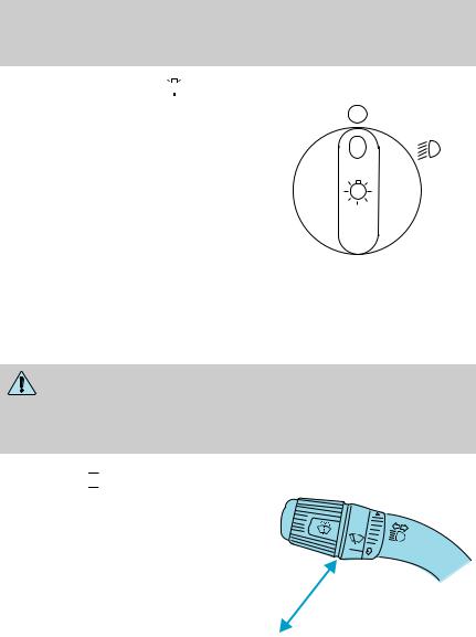
HEADLAMP CONTROL 


Rotate the headlamp control to the first position to turn on the parking lamps. Rotate to the second position to also turn on the headlamps.
Controls and features
P
Daytime running lamps (DRL) (if equipped)
Turns the headlamps on with a reduced output. To activate:
•the ignition must be in the ON position and
•the headlamp control is in the OFF or Parking lamps position.
Always remember to turn on your headlamps at dusk or during inclement weather. The Daytime Running Light (DRL) System
does not activate your tail lamps and generally may not provide adequate lighting during these conditions. Failure to activate your headlamps under these conditions may result in a collision.
High beams 

Push forward to activate.
Pull toward you to deactivate.
25

Controls and features
Flash to pass
Pull toward you to activate and release to deactivate.
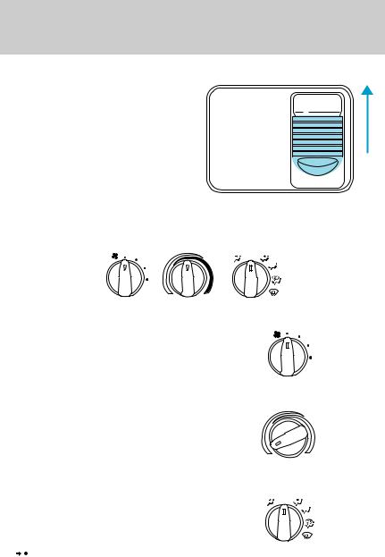
PANEL DIMMER CONTROL 
Use to adjust the brightness of the instrument panel during headlamp and parklamp operation.
•Rotate up to brighten.
•Rotate down to dim.
•Rotate to full up position (past detent) to turn on interior lamps.
4WD CONTROL (IF EQUIPPED)
This control operates the 4WD. Refer to the Driving chapter for more information.
PANEL
DIM
4X4
HIGH 4X4 2WD LOW
26
Controls and features
AUXILIARY POWER POINT 

The auxiliary power point is located on the instrument panel.
Do not plug optional electrical accessories into the cigarette lighter. Use the power point.
CLIMATE CONTROL SYSTEM Heater only system (if equipped)
POWER POINT
OFF
Fan speed control 
Controls the volume of air circulated in the vehicle.
Temperature control
Controls the temperature of the airflow inside the vehicle. On heater-only systems, the air cannot be cooled below the outside temperature.
Mode selector control
Controls the direction of the airflow to the inside of the vehicle.
OFF
• (Panel) -Distributes outside air through the instrument panel registers.
27

Controls and features
•OFF-Outside air is shut out and the fan will not operate.
• (Panel and floor) -Distributes outside air through the instrument panel registers and the floor ducts.
• (Floor) -Allows for maximum heating. Distributes outside air through the floor ducts.
• (Floor and defrost) -Distributes outside air through the floor ducts and the windshield defroster ducts.
• (Defrost) -Distributes outside air through the windshield defroster ducts. It can be used to clear ice or fog from the windshield.
Operating tips
•In humid weather, select  before driving. This will reduce fogging on your windshield. After a few minutes, select any desired position.
•To reduce humidity buildup inside the vehicle, don’t drive with the climate control system in the OFF position.
•Don’t put objects under the front seat that will interfere with the airflow to the rear seats (if equipped).
•Remove any snow, ice or leaves
from the air intake area (at the bottom of the windshield under the hood).
•Do not place objects over the defroster outlets. These objects can block airflow and reduce your ability to see through your windshield. Also, avoid placing small objects on top of your instrument panel. These objects can fall down into the defroster outlets and block airflow and possibly damage your climate control system.
Do not place objects on top of the instrument panel, as these objects may become projectiles in a collision or a sudden stop.
28
Controls and features
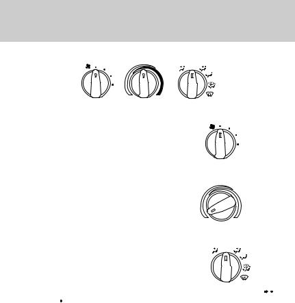
Manual heating and air conditioning system
OFF
A/C
MAX
A/C
Fan speed control 
Controls the volume of air circulated in the vehicle.
Temperature control knob
Controls the temperature of the airflow inside the vehicle.
Mode selector control
Controls the direction of the airflow to the inside of the vehicle.
OFF
A/C
MAX
A/C
The air conditioning compressor will operate in all modes except  (Panel) and
  (Floor). However, the air conditioning will only function if the outside temperature is about 10°C (50°F) or higher.
Since the air conditioner removes considerable moisture from the air during operation, it is normal if clear water drips on the ground under the air conditioner drain while the system is working and even after you have stopped the vehicle.
•MAX A/C-Uses recirculated air to cool the vehicle. MAX A/C is noisier than A/C but more economical and will cool the inside of the vehicle faster. Airflow will be from the instrument panel registers. This mode can also be used to prevent undesirable odors from entering the vehicle.
•A/C-Uses outside air to cool the vehicle. It is quieter than MAX A/C but not as economical. Airflow will be from the instrument panel registers.
29

Controls and features
• (Panel) -Distributes outside air through the instrument panel registers. However, the air will not be cooled below the outside temperature because the air conditioning does not operate in this mode.
•OFF-Outside air is shut out and the fan will not operate. For short periods of time only, use this mode to prevent undesirable odors from entering the vehicle.
• (Panel and floor) -Distributes outside air through the instrument panel registers and the floor ducts. Heating and air conditioning capabilities are provided in this mode. For added customer comfort, when the temperature control knob is anywhere in between the full hot and full cold positions, the air distributed through the floor ducts will be slightly warmer than the air sent to the instrument panel registers.
• (Floor) -Allows for maximum heating by distributing outside air through the floor ducts. However, the air will not be cooled below the outside temperature because the air conditioning does not operate in this mode.
• (Floor and defrost) -Distributes outside air through the windshield defroster ducts and the floor ducts. Heating and air conditioning capabilities are provided in this mode. For added customer comfort, the air distributed through the floor ducts will be slightly warmer than the air sent to the windshield defroster ducts. If the temperature is about 10°C (50°F) or higher, the air conditioner will automatically dehumidify the air to reduce fogging.
• (Defrost) -Distributes outside air through the windshield defroster ducts. It can be used to clear ice or fog from the windshield. If the temperature is about 10°C (50°F) or higher, the air conditioner will automatically dehumidify the air to reduce fogging.
Operating tips
•In humid weather, select  before driving. This will reduce fogging on your windshield. After a few minutes, select any desired position.
•To prevent humidity buildup inside the vehicle, don’t drive with the climate control system in the OFF or MAX A/C position.
•Don’t put objects under the front seat that will interfere with the airflow to the rear seats (if equipped).
30
Loading...