

Page 1
with HART®
ValveSight™ Diagnostics DTM Manual
Logix® MD+ Positioners
Page 2

ValveSight™ Diagnostics DTM Manual for Logix MD+ Positioner with HART®
FCD- LGENSF0014-00
Table of Contents
LOGIX MD+ .................................................................... 3
QUICK START GUIDE ................................................... 4
S
YSTEM REQUIREMENT
DTM I
NSTALLATION
C
REATE A FIELD NETWORK
DTM L
ICENSING
..................................................................................................... 6
......................................................................................................... 8
.............................................................................................. 10
............................................................................................................ 16
BASIC DASHBOARD ................................................... 17
ADVANCED DASHBOARD .......................................... 20
ANNUNCIATOR PANELS ............................................ 25
A
LARMS ANNUNCIATOR
M
ANAGEMENT ANNUNCIATOR
E
VENT HISTORY
.................................................................................................. 26
........................................................................................ 43
............................................................................................................. 55
HEALTH ....................................................................... 58
V
ALVE HEALTH
P
OSITIONER HEALTH
A
CTUATOR HEALTH
C
ONTROL HEALTH
T
RAINING
.............................................................................................................. 59
Friction .............................................................................................................. 64
Bellows Cycles & Travel ................................................................................... 72
....................................................................................................... 76
Teperature & Humidity .................................................................................... 82
Pilot Relay ........................................................................................................ 84
Piezo Voltage .................................................. ................................................. 88
........................................................................................................ 90
Actuator Pnuematic Leak ................................................................................. 94
Supply Pressure ................................................................................................ 97
Actuation Ratio .............................................................................................. 100
Actuator Cycles & Travel ................................................................................ 102
........................................................................................................ 106
Deviation ........................................................................................................ 110
Position Alerts ................................................................................................ 113
Command Frequency ..................................................................................... 116
Command Amplitude ..................................................................................... 119
Position Frequency ......................................................................................... 122
Position Amplitude ......................................................................................... 125
................................................................................................................... 128
ON-LINE DIAGNOSTICS ............................................ 130
D
ATA MONITOR
T
RENDS
C
ONTINUOUS STROKE TEST
.......................................................................................................... 131
...................................................................................................................... 137
............................................................................................ 142
OFF-LINE DIAGNOSTICS .......................................... 144
R
AMP TEST
© Flowserve Corporation 2
................................................................................................................. 145
Ramp Compare ............................................................................................... 155
Page 3

ValveSight™ Diagnostics DTM Manual for Logix MD+ Positioner with HART®
S
TEP TEST
................................................................................................................... 160
Step Test Compare ......................................................................................... 167
HDRL T
EST
................................................................................................................. 171
HDRL Compare ............................................................................................... 179
P
ARTIAL STROKE TEST
Partial Stroke Compare .................................................................................. 189
Partial Stroke Schedule .................................................................................. 193
................................................................................................... 183
FCD- LGENSF0014-00
CALIBRATION ........................................................... 195
S
ENSOR CALIBRATION
C
OMMAND CALIBRATION
C
ALIBRATION ERRORS
................................................................................................... 196
.............................................................................................. 202
................................................................................................... 206
CONFIGURATION ...................................................... 213
C
ONFIGURATION MANAGEMENT
DTM L
ICENSE MANAGEMENT
P
OSITIONER UPGRADE MANAGEMENT
P
OSITIONER UPGRADE
L
OCAL INTERFACE
C
ONTROL
.................................................................................................................... 237
Position Shutoff .............................................................................................. 238
Soft Limits ....................................................................................................... 240
Positioner Gain ............................................................................................... 242
Pressure Control ............................................................................................. 245
Stroke Characterization ................................................................................. 247
I
NFORMATION
Actuator ......................................................................................................... 260
Valve Body ...................................................................................................... 262
Valve Trim ...................................................................................................... 264
Positioner & HART® Information ................................................................... 266
C
ARD SLOT
U
NITS
................................................................................................................. 268
Multi-Function Card ....................................................................................... 269
........................................................................................................................ 277
.................................................................................................. 229
......................................................................................................... 231
Stroke Characterization (Custom) ................................................................... 254
............................................................................................................. 259
Analog Output Calibration ............................................................................... 271
Discrete Output (DO) ........................................................................................ 275
.................................................................................... 214
........................................................................................ 223
............................................................................ 225
© Flowserve Corporation 3
Page 4
ValveSight™ Diagnostics DTM Manual for Logix MD+ Positioner with HART®
FCD- LGENSF0014-00
Welcome to the Logix MD+
Welcome to the Flowserve ValveSight® DTM for the Logix MD+ series digital
positioners. This package offers unparalleled functionality for configuring, calibrating,
maintaining and diagnosing control valve operation.
This package follows the standard FDT/DTM conventions. The Frame application
controls the menu bar at the top of the page and the Frame connection tree at the far
left of the frame window.
The DTM application contains a menu tree on the left side showing the available
pages for configuring, calibrating, maintaining and diagnosing control valve operation.
At the top of the DTM window, the device tag is shown, and some basic information
for the actuator and valve that is currently connected to the system.
The bar right below the device information contains two icons, one to toggle the menu
bar on and off and the other to show this help.
At the bottom of the page below the Flowserve logo is an icon indicating the status of
the connection to the field device. If the icon has a green check and the tow plugs
touching it indicates that communications are taking place and the device shown at
the top of the page is online. Two green arrows to the right of the connection symbol
are visible when the DTM is requesting information from the device.
© Flowserve Corporation 4
Page 5

ValveSight™ Diagnostics DTM Manual for Logix MD+ Positioner with HART®
FCD- LGENSF0014-00
Quick Start Guide
GENERAL INFORMATION
This Document
This document details the installation and functions of the ValveSight® Device Type
Manager (ValveSight DTM) for the Logix® MD+ series of digital positioners including
the Logix 520MD+.
Qualified Personnel
Qualified personnel are people who, on account of their training, experience and
instruction and their knowledge of relevant standards, specifications, accident
prevention regulations and operating conditions, have been authorized by those
responsible for the safety of the plant to perform the necessary work and who can
recognize and avoid possible dangers.
Additionally, product users and maintenance personnel should thoroughly review the
Logix MD+ Series Digital Positioner Instruction, Operation, Maintenance and Safety
Manual prior to installing, operating, or performing maintenance on the valve or
positioner.
System Disclaimer
The installation instructions herein show an example of how to install, navigate, or
commission the ValveSight Logix MD+ DTM in a WINDOWS 7 64 bit operating
system, using the fdtCONTAINER FRAME Application. Any variation of operating
system and/or FRAME application may result in a different procedure to install,
operate, or commission the ValveSight Software.
Terms Concerning Safety
The safety terms DANGER, CAUTION and NOTE are used in these instructions to
highlight particular dangers and/or to provide additional information on aspects that
may not be readily apparent.
To avoid possible injury to personnel or damage to valve parts, DANGER and
CAUTION notes must be strictly followed. Modifying this product, substituting nonfactory parts or using maintenance procedures other than outlined could drastically
affect performance and be hazardous to personnel and equipment, and may void
existing warranties.
NOTE: indicates and provides additional technical information, which may not be very
obvious even to qualified personnel.
CAUTION: Indicates that minor personal injury and/or property damage can occur if
proper precautions are not taken.
© Flowserve Corporation 5
Page 6

ValveSight™ Diagnostics DTM Manual for Logix MD+ Positioner with HART®
FCD- LGENSF0014-00
DANGER: Indicates that death, severe personal injury and/or substantial property
damage can occur if proper precautions are not taken.
Compliance with other, not particularly emphasized notes, with regard to transport,
assembly, operation and maintenance and with regard to technical documentation
(e.g., in the operating instruction, product documentation or on the product itself) is
essential, in order to avoid faults, which in themselves might directly or indirectly
cause severe personal injury or property damage.
© Flowserve Corporation 6
Page 7

ValveSight™ Diagnostics DTM Manual for Logix MD+ Positioner with HART®
FCD- LGENSF0014-00
System Requirement
Computer System
The ValveSight® DTM has been successfully tested with the following Operating
System with a minimum of 512 M RAM:
• Windows XP
• Windows 7
Power Supply
• Non-filtered, 4-20 mA
Modem
• IFAC HART Modem
• Viator RS 232 Serial HART Modem
• UX Multiplexor
Communication DTM
• CodeWrite COMM DTM
• M&M – OEM HART COMM DTM (recommended)
• Yokogawa COMM DTM
• ABB COMM DTM
FRAMES
The ValveSight Logix MD+ DTM has been successfully tested in the following FRAME
Applications:
• fdtCONTAINER FRAME Application
• PactWare (Point to Point) FRAME Application
DD Testing
The DD has been successfully tested on the following system components:
• HART Tokenizer Version 6
• SDC-625
• 475 HandHeld
Certifications
• Logix MD+ DTM Certification with FDT Group will be performed after field trial
tests.
• DD Certification with the HART foundation will be performed after field trial
tests.
System Assumptions
This Quick Start Guide document will assume that you already have the FRAME
Application and Communication DTM installed.
© Flowserve Corporation 7
Page 8
ValveSight™ Diagnostics DTM Manual for Logix MD+ Positioner with HART®
FCD- LGENSF0014-00
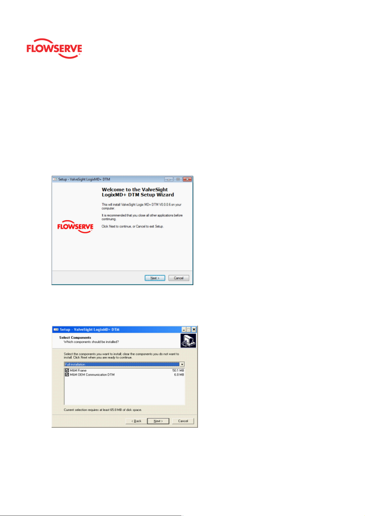
DTM Installation
Please log in to the Flowserve FTP Site (ftp://fcdftp) or open the CD to download the
Logix MD+ ValveSight DTM, FdtCONTAINER, or HART COMM DTM Installs. These
installs will allow you to install the ValveSight Logix MD+ DTM, FRAME application,
and COMM DTM respectively.
NOTE: This document will ONLY cover the installation of the Logix 520MD+
ValveSight DTM.
Follow the installation instructions
Frame and COMM DTM Install
If you do not have the FRAME Application or the HART Communication DTM
installed, check the two boxes below and follow the installation instruction for both
Frame and Communication DTM, else uncheck the already installed component.
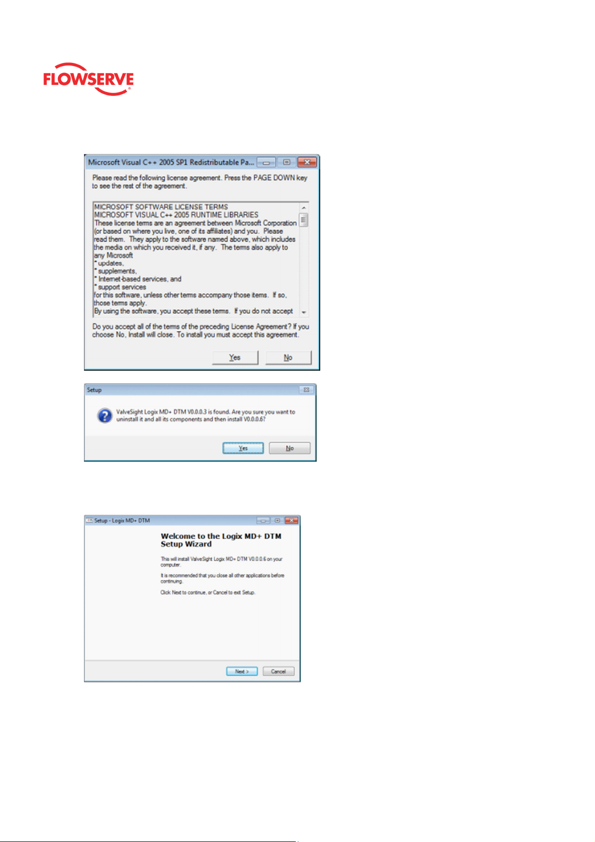
Runtime Libraries
The ValveSight installation will check to see if the computer already has the
necessary Microsoft Libraries, else it will prompt you to install the Libraries. Select
© Flowserve Corporation 8
Page 9
ValveSight™ Diagnostics DTM Manual for Logix MD+ Positioner with HART®
“Yes” on the following pages.
FCD- LGENSF0014-00
Resuming ValveSight Install
Once the install complete the installation and the Dongle and the Microsoft Runtime
Libraries it will resume the installation of the DTM. Click Next
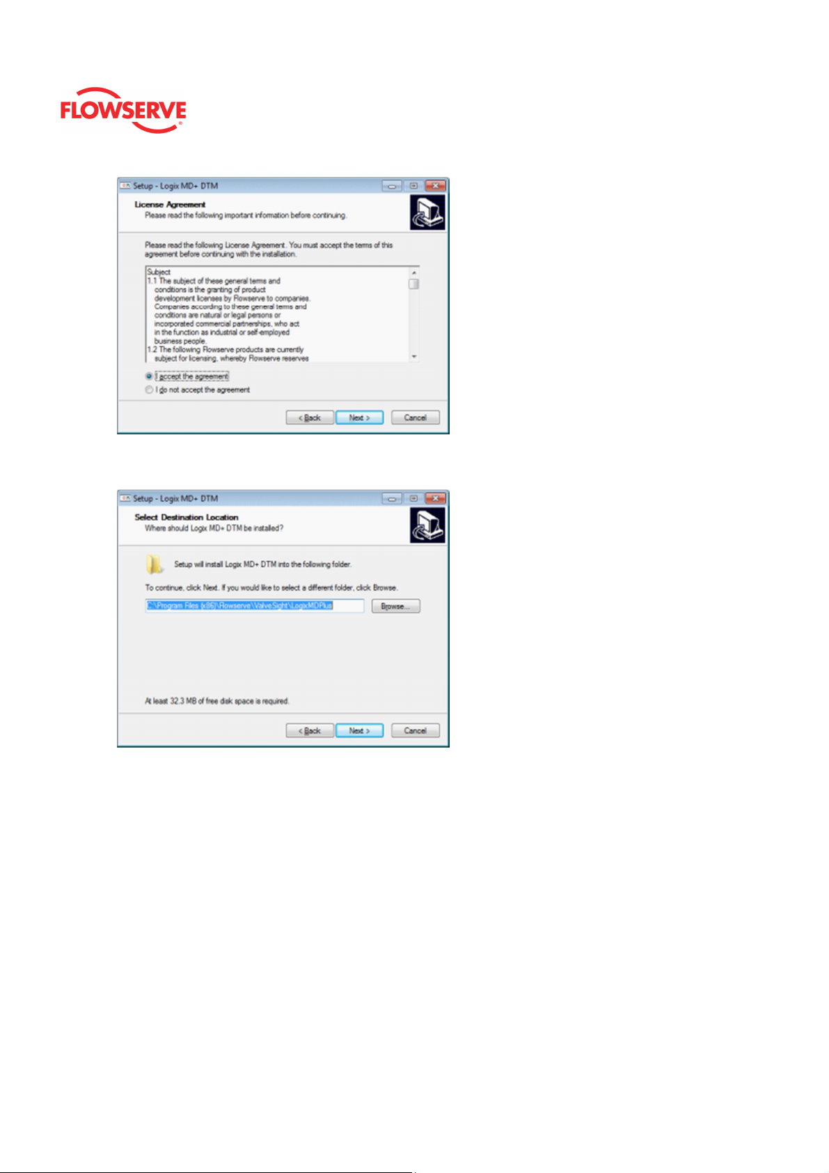
Accept the Agreement
Read and accept the agreement, then click next.
© Flowserve Corporation 9
Page 10
ValveSight™ Diagnostics DTM Manual for Logix MD+ Positioner with HART®
Select DTM destination
Browse and select the location where the DTM will install:
FCD- LGENSF0014-00
Follow and complete the installation as prompted.
© Flowserve Corporation
10
Page 11
ValveSight™ Diagnostics DTM Manual for Logix MD+ Positioner with HART®
Create a Field Network
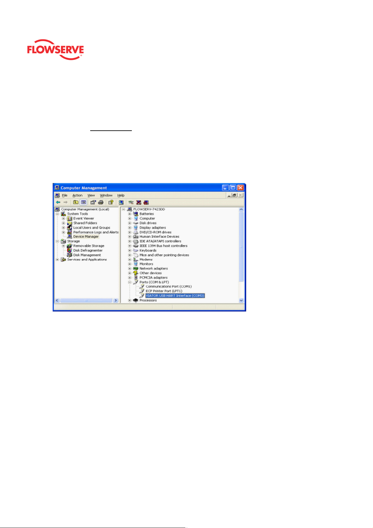
HART Modem
• If the modem is a serial port, move on to the next step
• The USB Modem requires that you install the driver for it. Make sure you
remember what slot you put the USB Driver, in case you unplug and plug in a
different slot you will need to install the driver for the different slot.
• Right Click on My Computer and select Manage.
• Click on Device Manager and select Ports
• Check what port the modem was installed
FCD- LGENSF0014-00
Create a Field Network
The remainder of the Quick Start Guide will give instructions on how to create a Field
Network using the fdtCONTAINER FRAME Application.
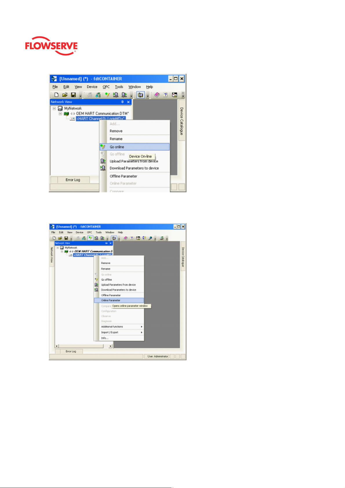
Device Catalog
Double click on the FDT Container, which is the M&M • Frame to open it. You will see
a widow on the right of the page called “Device Catalog”. At the bottom of the page,
click on Update. This should allow the Frame to identify both the COMM DTM and the
ValveSight DTM.
© Flowserve Corporation
11
Page 12

ValveSight™ Diagnostics DTM Manual for Logix MD+ Positioner with HART®
FCD- LGENSF0014-00
Add the COMM DTM
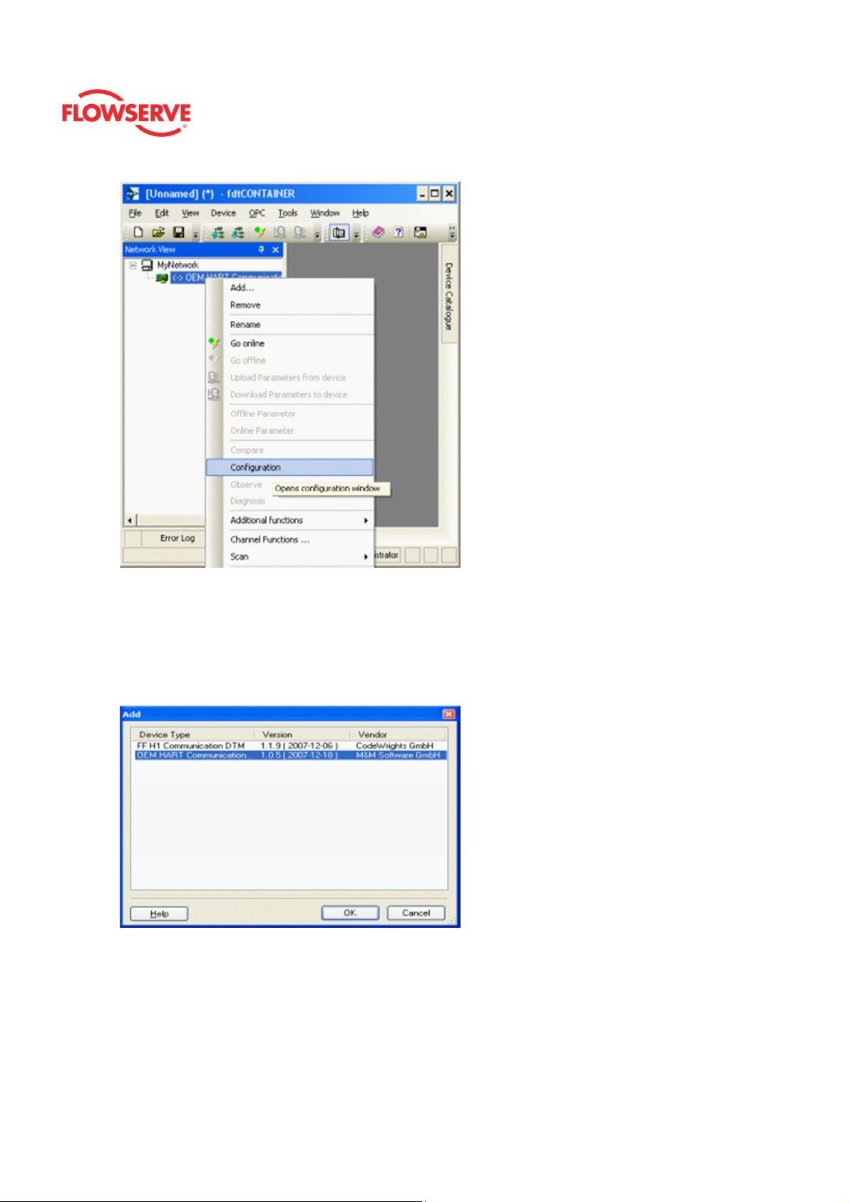
On the left side of the page you will see a window “Network View”. Right click on the
My Network icon. Select “Add…”
To configure the communication port, right click the OEM HART Communication DTM
in the “Network Views” window. Select “Configuration”.
© Flowserve Corporation
12
Page 13
ValveSight™ Diagnostics DTM Manual for Logix MD+ Positioner with HART®
FCD- LGENSF0014-00
Set Port Address
• Select the correct port where the modem is installed.
• Check with the modem manufacturer to select the correct “Access Mode”.
• Under the “Communications Mode”, set the correct “Access Mode”
• Click the Apply or Ok button to apply modem configuration changes.
Add ValveSight Logix MD+ DTM
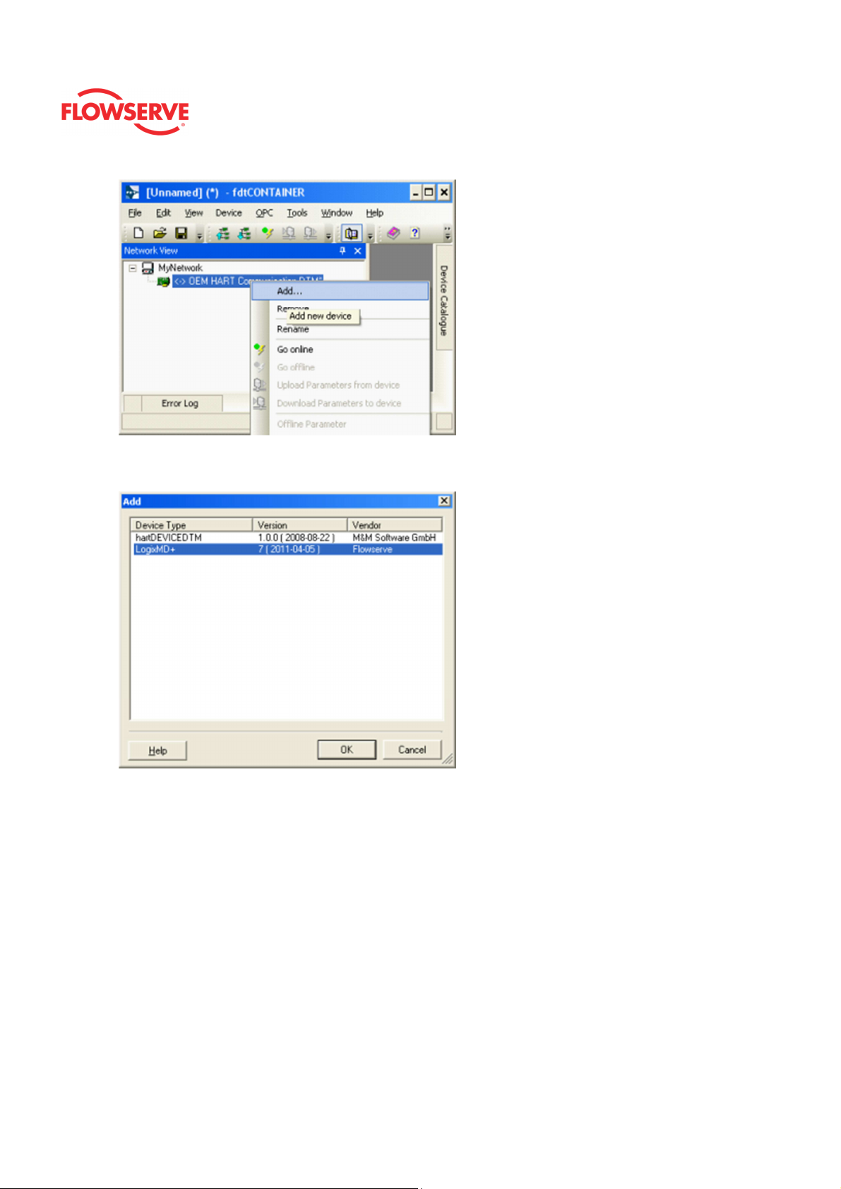
To add the ValveSight Logix MD+ DTM, right click on the OEM HART Communication
DTM in the “Network Views” window and select “Add”.
© Flowserve Corporation
13
Page 14
ValveSight™ Diagnostics DTM Manual for Logix MD+ Positioner with HART®
Select the “LogixMD+”
FCD- LGENSF0014-00
Optional: Save the project to your desktop or somewhere easy to remember. This will
save you time so you do not have to create a field network in the future.
Starting the ValveSight MD+ DTM
To launch the ValveSight DTM, ensure the modem is connected to a device and the
device is powered on.
Right click on the “HART Channel 0> LogixMD+” and select “Go Online”
© Flowserve Corporation
14
Page 15
ValveSight™ Diagnostics DTM Manual for Logix MD+ Positioner with HART®
FCD- LGENSF0014-00
Double click the “HART Channel 0> LogixMD+”, or right click and select Online
Parameter
Troubleshooting
If communications is not established:
1. Verify the HART modem is functional. Some HART modems will report a positive
self-check, but still be non-functional.
2. If another primary master is connected in the system, use a communication DTM
other than the M&M fdtCONTAINER. This communication DTM does not support a
primary master other than itself.
© Flowserve Corporation
15
Page 16

ValveSight™ Diagnostics DTM Manual for Logix MD+ Positioner with HART®
FCD- LGENSF0014-00
DANGER: Using certain features of the DTM can result in valve movement and the
inability to operate the valve until the operation is complete. Notify proper personnel
that the valve may stroke, and make sure the valve is properly isolated before
proceeding.
© Flowserve Corporation
16
Page 17

ValveSight™ Diagnostics DTM Manual for Logix MD+ Positioner with HART®
FCD- LGENSF0014-00
DTM Licensing
License ValveSight
To take advantage of the full diagnostic capabilities of ValveSight®, license the
Advanced ValveSight DTM for the Logix MD+.
Steps to license the Advance DTM:
1. In the menu tree, select “Configuration” -> “DTM License Management”
2. Write “beta” in the “Feature code:” (make sure it is all lower case)
3. Click the “Activate / Deactivate”
NOTE: The ValveSight Advance License will only apply to the specific PC.
© Flowserve Corporation
17
Page 18
ValveSight™ Diagnostics DTM Manual for Logix MD+ Positioner with HART®
FCD- LGENSF0014-00
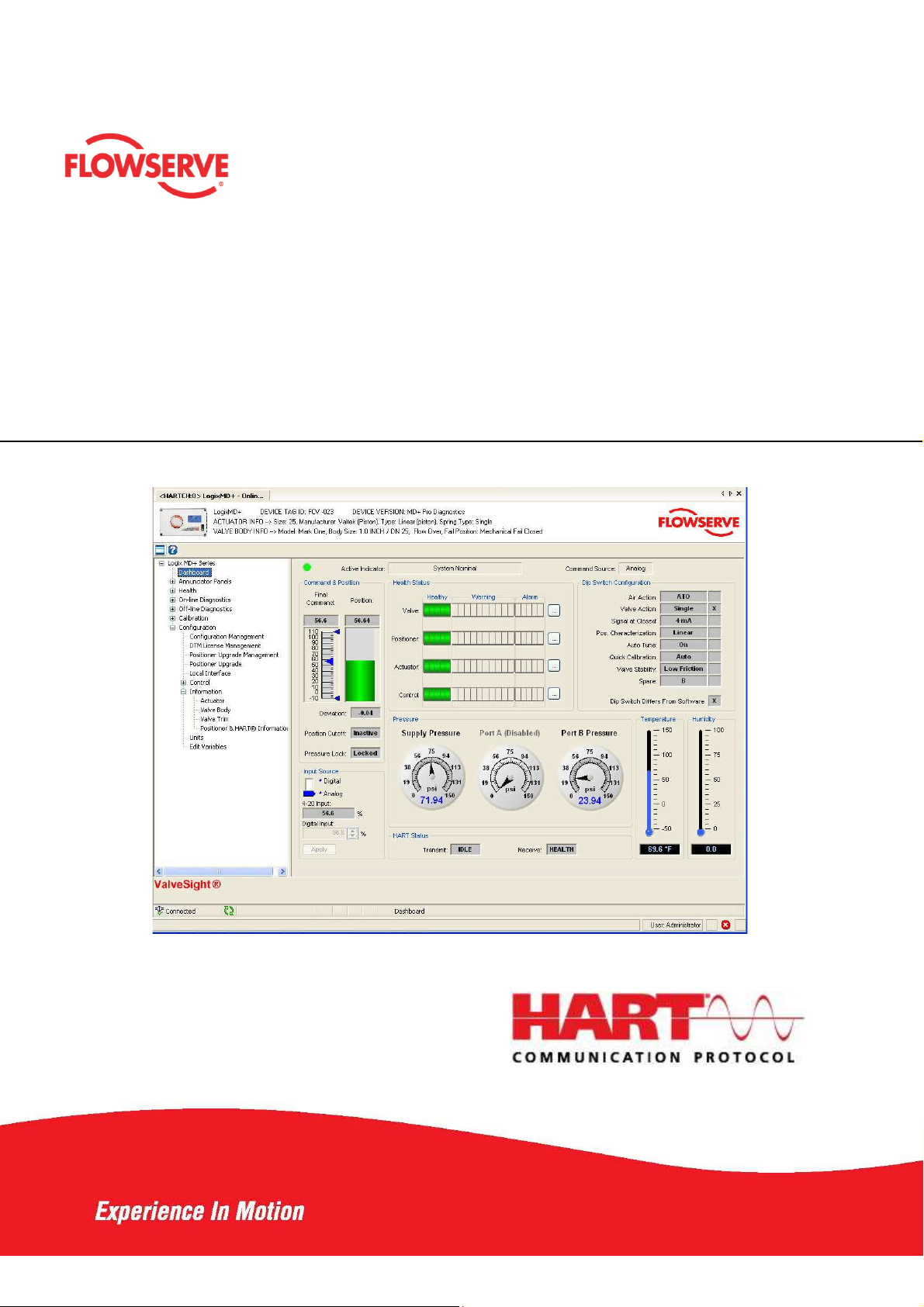
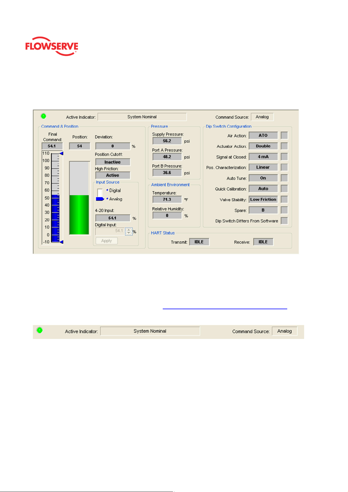
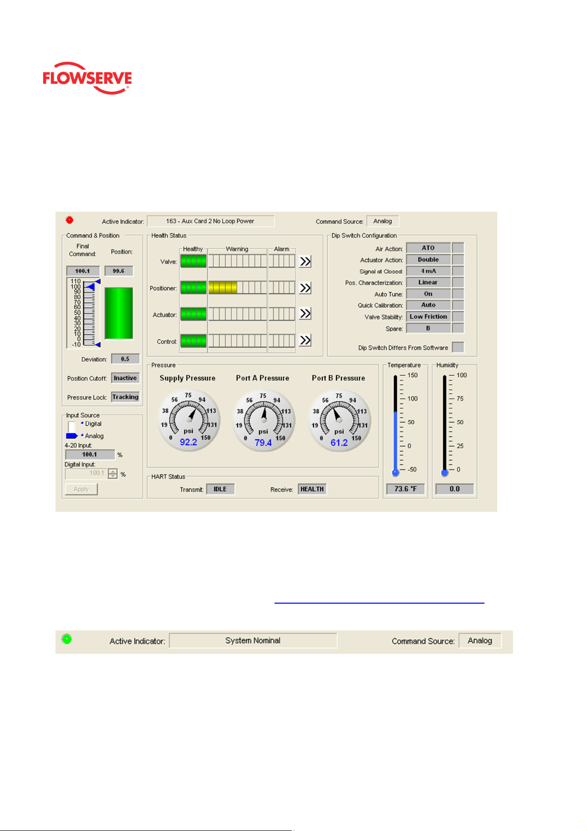
Basic Dashboard
The Basic Dashboard is a high level view of the status of the positioner. It is the main view
of the ValveSight® DTM.
Status Area
The Active Indicator area shows the status of the most relevant active indicator. The color
of the "LED light" corresponds to the Active Indicator and the first color of the blink code
sequence on the positioner. Generally green indicates no immediate issues. Yellow
indicates a developing issue. Red indicates the ability to control may be compromised. A
detailed list of the indicators is given in the Alarm Congfiguraion - Alarm Annunicator page.
The Command Source field indicates weather the positioner is being controlled by digital or
an analog (4-20 mA) command source.
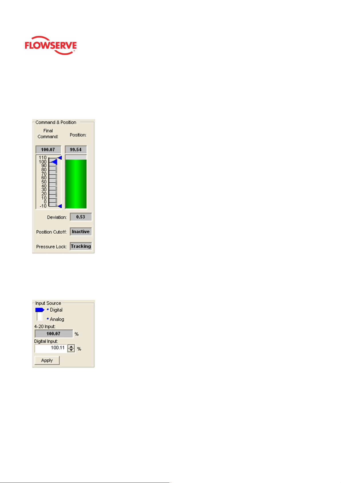
Command and Position
This area contains a graphical representations of the valve command and position. The
blue bar tracks the final command value (after adjustments for characterization curves).
The green position bar indicates the current measured position of the valve. The smaller
pointers show the settings of the travel alert settings (these can be changed on the Travel
Alerts page located under Alarms/Alerts). Grayed out zones at the top or bottom of the
graphs indicate the settings of soft travel limits.
© Flowserve Corporation
18
Page 19
ValveSight™ Diagnostics DTM Manual for Logix MD+ Positioner with HART®
FCD- LGENSF0014-00
Input Source
Select the analog or digital control mode. In analog mode, the positioner will position the
valve according to the 4-20 mA supplied current. In digital mode, the positioner will position
according to the value entered in the Digital Input field.
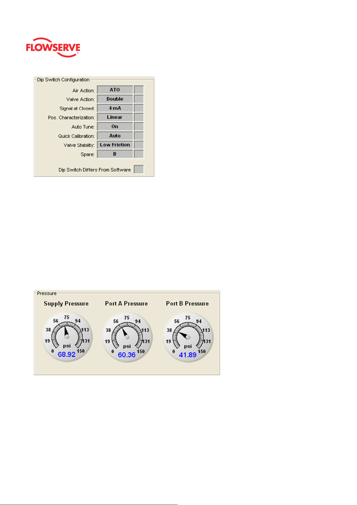
Pressure
Supply, port A and port B pressures are seen in this box. If the Supply Pressure field is
yellow or red, there is a problem with the supply pressure to the positioner. The fields in the
Pressure box are only active if the positioner is upgraded to have Advanced or Pro
diagnostics.
© Flowserve Corporation
19
Page 20
ValveSight™ Diagnostics DTM Manual for Logix MD+ Positioner with HART®
FCD- LGENSF0014-00
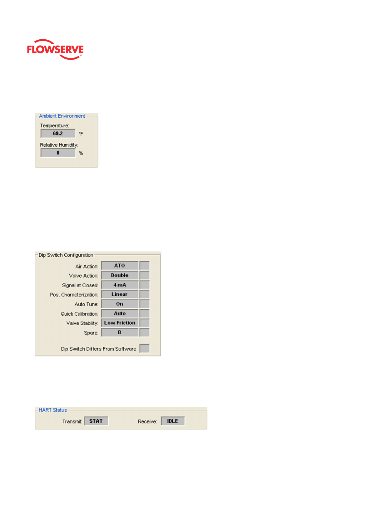
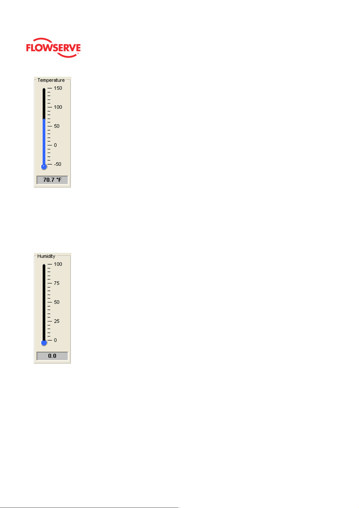
Ambient Temperature
The temperature and relative humidity inside the positioner are shown here. The units for
temperature can be changed in the Positioner Configuration - Units page.
Dip Switch Configuration
The box shows the current configuration of the DIP switches on the front of the positioner.
These switches should be set on the positioner before calibration. The configuration that is
set by the DIP switches can be overridden in the software using the DTM. (See the
Basic/Local Interface page of the DTM). If this is the case, an X will be shown in the box to
the right of the item. Be careful when changing the configuration in software because
performing a position calibration (Quick-Cal) will reset the configuration according to the
physical DIP switch settings. See you instructions for the positioner for a detailed
explanation of the switches.
HART Status
Communication with the DTM is displayed here. The Transmit field displays a data packet
transmitted to the positioner. The Receive field shows data packets received from the
positioner. These are constantly updating. If they appear static, there may be a problem
with communications.
© Flowserve Corporation
20
Page 21
ValveSight™ Diagnostics DTM Manual for Logix MD+ Positioner with HART®
FCD- LGENSF0014-00
Advanced Dashboard
The Dashboard view is the main diagnostic view of the ValveSight® DTM. Generally, the
color green signifies a healthy condition, yellow signifies some degradation has taken
place, and red signifies a problem that needs to be addressed right away. You can identify
problems right away by observing any red areas on this page.
Status Area
The Active Indicator area shows the status of the most relevant active indicator. The color
of the "LED light" corresponds to the Active Indicator and the first color of the blink code
sequence on the positioner. Generally green indicates no immediate issues. Yellow
indicates a developing issue. Red indicates the ability to control may be compromised. A
detailed list of the indicators is given in the Alarm Congfiguraion - Alarm Annunicator page.
The Command Source field indicates weather the positioner is being controlled by digital or
an analog (4-20 mA) command source.
Command and Position
This area contains a graphical representations of the valve command and position. The
blue pointer tracks the final command value after adjustments for characterization curves,
Soft Limits, and Tight Shut Off. The green position bar indicates the current measured
position of the valve. The smaller pointers show the settings of the travel alert settings
(these can be changed on the Travel Alerts page located under Alarms/Alerts). Grayed out
© Flowserve Corporation
21
Page 22
ValveSight™ Diagnostics DTM Manual for Logix MD+ Positioner with HART®
FCD- LGENSF0014-00
zones at the top or bottom of the graphs indicate the settings of Soft Limits. The command
chart also displays the settings for travel limits and position Tight Shut Off (Minimum
Position Cut Off (MPC)) limits. If the positioner has been configured for Tight Shut Off this
will show up in the field below the position bar. The Pressure Lock field indicates if the
positioner is locked on a steady command by controlling the pressures, or tracking a
moving command signal.
Input Source
The command source can be changed to analog or digital mode. In analog mode, the
positioner will position the valve according to the 4-20 mA supplied current. In digital mode,
the positioner will position the valve according to the value entered in the Digital Input field.
HART Status
The status of HART communication with the DTM is displayed here. The Transmit field
displays a data packet transmitted to the positioner. The Receive field shows data packets
received from the positioner. These are constantly updating. If they appear static, there
may be a problem with communications.
© Flowserve Corporation
22
Page 23

ValveSight™ Diagnostics DTM Manual for Logix MD+ Positioner with HART®
FCD- LGENSF0014-00
Health Status
The Health Status box has health indication bars for Valve, Position, Actuator, and Control
which are displayed in 4 bar graphs in the center of the dashboard. These are powerful,
visual diagnostic tools. Information from all of the diagnostic indications are rolled up into
these health bars. As the graphs turn color (from green to yellow to red) they indicate
developing issues. The health of the four key components of a control valve can be
identified quickly by looking at the color of the bar. If the bars only show green then
everything is operating within normal limits and no further action is required. If the bar is
partially yellow it is pointing out a degraded condition. The further the bar goes to the right
the more serious the degradation. If the bar is red then action should be taken immediately
because the ability to control may be compromised. To learn more about any of the 4
health areas, click the double arrows ( ) button at the end of the bar. This leads to the
detailed health status page for that particular item.
NOTE: Health Status bars are only available with the Advanced ValveSight® license
viewing positioners with Advanced or Pro diagnostics. See the licensing and upgrade
pages under Positioner Configuration in the DTM for more information.
Dip Switch Configuration
The box shows the current configuration of the DIP switches on the front of the positioner.
These switches should be set on the positioner before calibration. The configuration that is
set by the DIP switches can be overridden in the software using the DTM. (See the
Basic/Local Interface page of the DTM). If this is the case, an X will be shown in the box to
the right of the item. Be careful when changing the configuration in software because
performing a position calibration (Quick-Cal) will reset the configuration according to the
physical DIP switch settings. See you instructions for the positioner for a detailed
explanation of the switches.
© Flowserve Corporation
23
Page 24
ValveSight™ Diagnostics DTM Manual for Logix MD+ Positioner with HART®
FCD- LGENSF0014-00
Pressure
Pressure values are shown here. The units for pressure can be changed in the Positioner
Configuration - Units page. The pressure gages for Port 1 and Port 2 read directly from the
pressure sensors in the positioner. For single acting configurations, the Port 2 gage is not
be active. Should the DTM view a device with no pressure sensors, all 3 gauges will be
inactive. Pressure sensors are calibrated in the factory. A pressure calibration is not
required unless there has been sever pressure or thermal stress on the positioner. See the
Calibration - Sensor Calibration page.
NOTE: Pressure gauges are only available while viewing positioners with Advanced or Pro
diagnostics. See the Positioner Upgrade page under Positioner Configuration in the DTM
for more information.
Temperature
This gage shows the temperature on the circuit board in the positioner. The units for
temperature can be changed in the Positioner Configuration - Units page.
© Flowserve Corporation
24
Page 25
ValveSight™ Diagnostics DTM Manual for Logix MD+ Positioner with HART®
FCD- LGENSF0014-00
Humidity
This gage shows the Humidity on the circuit board inside the positioner. Since the
positioner should be run with a dry air supply, this value should be near zero most of the
time. Elevated humidity inside the positioner may significantly shorten the life of the
positioner. Sensor accuracy is +/-10% RH. The sensors are calibrated in the factory. No
other calibration is required.
© Flowserve Corporation
25
Page 26

ValveSight™ Diagnostics DTM Manual for Logix MD+ Positioner with HART®
FCD- LGENSF0014-00
Annunciator Panels
Annunciator Panels allow quick viewing of the current state and history of diagnostic
indicators and allows masking of alarms, warnings and alerts. This selection automatically
redirects to the Alarms Annunciator page.
© Flowserve Corporation
26
Page 27
ValveSight™ Diagnostics DTM Manual for Logix MD+ Positioner with HART®
FCD- LGENSF0014-00
Alarms Annunciator
The Alarm Annunciator page displays the status of all
diagnostic indicators. The status is shown in by the indicator "light". The checkboxes allow
masking of indicators.
Status Area
The Active Indicator area shows the status of the most relevant active indicator. The color
of the "LED light" corresponds to the Active Indicator and the first color of the blink code
sequence on the positioner. Generally green indicates no immediate issues. Yellow
indicates a developing issue. Red indicates the ability to control may be compromised. A
detailed list of the indicators is given below. The Command Source field indicates weather
the positioner is being controlled by digital or an analog (4-20 mA) command source.
© Flowserve Corporation
27
Page 28
ValveSight™ Diagnostics DTM Manual for Logix MD+ Positioner with HART®
Legend
Each indicator group box may contain the following components:
• An "LED light" indicates health status. Warning and alarm limits (set by the
user in many cases) determine the conditions when the color will turn from
green to yellow to red. The most sever of the indicators on this page will be
shown in the health bar on the Dashboard.
• Dark Green circle indicates a healthy condition where no attention is
needed.
• Light Green indicates an occurrence of a normal activity that does
not affect the health of the valve system.
• Yellow circle indicates that an active warning, alert or mode is
present.
• Red circle indicates that an active alarm or state is present that
could seriously limit the operation of the valve.
• Gray circle indicates that the feature or condition is not available
because the configuration of the hardware or software does not support
it.
• A checkbox indicates the masked status. Check to mask. If a particular
indicator is masked, it will not be shown in the active indicator field at the top
of each screen, affect the status of the health bars on the main dashboard, be
sent in command 48, or be seen on the blinking LEDs on the positioner. It
will however continue to show on this page.
FCD- LGENSF0014-00
Cycles & Travel Status
Valve Cycles
• Definition: The valve cycle limit has been exceeded.
© Flowserve Corporation
28
Page 29

ValveSight™ Diagnostics DTM Manual for Logix MD+ Positioner with HART®
• Implications: Each cycle represents two reversals of the direction of
valve movement. The cycle counting criterion and count limit are set by
the user to track the usage of the valve.
• Possible Solutions: Follow routine procedures for maintenance when
the limit is reached such as checking the packing tightness, and
checking linkages for wear, misalignment, and tightness. After
maintenance, reset the cycle accumulator.
Valve Travel
• Definition: The total accumulated valve travel limit has been
exceeded.
• Implications: The travel is accumulated in both directions. The travel
counting criterion and limit are set by the user to track the usage of the
valve.
• Possible Solutions: Follow routine procedures for maintenance when
the limit is reached such as checking the packing tightness, and
checking linkages for wear, misalignment, and tightness. After
maintenance, reset the travel accumulator.
Actuator Cycles
• Definition: The actuator cycle limit has been exceeded.
• Implications: Each cycle represents two reversals of the direction of
valve movement. The cycle counting criterion and count limit are set by
the user to track the usage of the valve.
• Possible Solutions: Follow routine procedures for maintenance when
the limit is reached such as checking the actuator seals and
lubrication. After maintenance, reset the travel accumulator.
Actuator Travel
• Definition: The total accumulated actuator travel limit has been
exceeded.
• Implications: The travel is accumulated in both directions. The travel
counting criterion and limit are set by the user to track the usage of the
valve.
• Possible Solutions: Follow routine procedures for maintenance when
the limit is reached such as checking the actuator seals and
lubrication. After maintenance, reset the travel accumulator.
Bellows Cycles
• Definition: The bellows cycle limit has been exceeded.
• Implications: The bellows may be reaching the end of its fatigue
life. Each cycle represents two reversals of the direction of bellows
movement. The cycle counting criterion and count limit are set by the
user to track the usage of the valve.
• Possible Solutions: Follow routine procedures for maintenance when
the limit is reached such as checking bellows for cracking or
leaking. After maintenance, reset the cycle accumulator.
Bellows Travel
• Definition: The bellows cycle limit has been exceeded.
FCD- LGENSF0014-00
© Flowserve Corporation
29
Page 30

ValveSight™ Diagnostics DTM Manual for Logix MD+ Positioner with HART®
• Implications: The bellows may be reaching the end of its fatigue
life. Each cycle represents two reversals of the direction of valve
movement. The cycle counting criterion and count limit are set by the
user to track the usage of the valve.
• Possible Solutions: Follow routine procedures for maintenance when
the limit is reached such as checking bellows for cracking or
leaking. After maintenance, reset the cycle accumulator.
Pilot Cycle
• Definition: The pilot relay cycle limit set by the user has been
exceeded.
• Implications: The pilot relay cycles indicate the activity level of the pilot
relay as it maintains a valve’s position. Excessive cycles can contribute
to a worn relay which can lead to high air consumption.
• Possible Solutions: Inspect for high air consumption and signs of
wear.
Pilot Travel
• Definition: The total accumulated pilot relay travel (% of full relay span)
set by the user has been exceeded.
• Implications: The pilot relay travel indicates the activity level of the
relay as it maintains a valve’s position. Excessive travel can contribute
to a worn pilot relay which can lead to high air consumption.
• Possible Solutions: Inspect for high air consumption and signs of
wear.
Feedback Loop Status
FCD- LGENSF0014-00
Position Deviation
• Definition: The device is not controlling at the set point.
• Implications: The difference between the command and the actual
position has been greater than the user-set limit for longer than a userset time.
• Possible Solutions: Review active alarms and warnings to find root
causes of this alarm. The deviation settings can be changed in the
Valve Health page of the DTM.
Position Sensor Fail
• Definition: The feedback arm may be disconnected from the valve
assembly.
• Implications: The feedback arm may be disconnected from the valve
assembly or the sensor has failed.
© Flowserve Corporation
30
Page 31

ValveSight™ Diagnostics DTM Manual for Logix MD+ Positioner with HART®
• Possible Solutions: Check the feedback arm linkage. Recalibrate. If
the problem persists return the unit for repair.
Closed Too Far
• Definition: The valve has closed farther than it did at the last
calibration.
• Implications: While the valve was in use, it closed farther than it did at
the last calibration by 0.5%.
• Possible Solutions: Check the feedback arm linkage and ensure the
valve stem connection is tight. Recalibrate the stroke. If the process
cannot be interrupted a service technician may be able to adjust the
calibration.
Opened Too Far
• Definition: The valve has opened farther than it did at the last
calibration.
• Implications: While the valve was in use, it opened farther than it did at
the last calibration by 0.5%.
• Possible Solutions: Check the feedback arm linkage and ensure the
valve stem connection is tight. Recalibrate the stroke. If the process
cannot be interrupted a service technician may be able to adjust the
calibration.
PST Failed -
• Definition: Measured times or forces during the last partial stroke test
did not pass the criteria set by the user.
• Implications: This may be an indication of corrosion build-up on the
valve stem or in the actuator, low or restricted supply pressure, or a
sticking positioner relay.
• Possible Solutions: This warning will clear upon completion of a
successful partial stroke test.
CST Failed
• Definition: During the continuous stroke test, the valve did not move
after 5 consecutive attempts.
• Implications: This could mean the valve has increased friction, a
change in process load or inadequate supply pressure.
• Possible Solutions: Check friction, supply pressure and other alarms
or warnings that would indicate difficulty in moving the valve. Check
packing, and air supply. The warning will clear when the CST function
is turned off or when a successful attempt to move the valve occurs.
Inner Loop Status
FCD- LGENSF0014-00
© Flowserve Corporation
31
Page 32

ValveSight™ Diagnostics DTM Manual for Logix MD+ Positioner with HART®
Pilot Response
• Definition: The pilot relay is sticking or slow to respond.
• Implications: This affects the responsiveness, increases the chance of
limit cycling and excessive air consumption. The pilot relay is part of the
inner loop and consists of the driver module assembly with piezo (I-P
relay) which is coupled to the spool valve or poppet. The value of this
indicator corresponds with inner loop lag. Delayed response can be
caused by a partially clogged piezo or debris, oil, corrosion, or ice on
the spool, or low supply pressure.
• Possible Solutions: Check response of the valve. If OK, adjust Pilot
Relay Response limits. Check supply pressure. Check the spool or
poppet for debris, oil, corrosion, ice on the spool. Clean or replace the
spool or poppet assembly. Replace the piezo or driver module
assembly. Maintain a clean, water-free air/gas supply.
Piezo Volts High
• Definition: The voltage driving the piezo is above the warning limit.
• Implications: This could indicate an error with the relay or the main
board. This may result from an extended period of inactivity, but in this
case should not persist for more than 30 minutes when the valve is
controlling. The positioner may still be functioning, but have reduced
performance under some circumstances.
• Possible Solutions: Ensure the supply pressure is not low. If alarm
persists for more than 30 minutes, the Piezo assembly is
damaged. Replace the pilot relay.
Piezo Volts Low
• Definition: The voltage to the piezo is too low.
• Implications: The piezo may be damaged. This may prevent the
proper failure position upon loss of signal/power. This condition may
occur briefly on an air-to-close valve that is held for long periods of time
in the closed position, or an air-to-open valve held in the open position.
• Possible Solutions: Ensure the supply pressure is not low. If alarm
persists for more than 30 minutes, the Piezo assembly is
damaged. Replace the pilot relay.
Driver Module
• Definition: Driver module alarm.
• Implications: The pilot relay can't open, the pilot relay can't shut, or the
Hall sensor circuit has failed.
• Possible Solutions: Check the internal wiring connections. Replace
the pilot relay.
Control Status
FCD- LGENSF0014-00
Command Frequency
© Flowserve Corporation
32
Page 33

ValveSight™ Diagnostics DTM Manual for Logix MD+ Positioner with HART®
• Definition: The frequency of the command signal is above the warning
or alarm limit. This could mean the control loop is oscillating faster than
normal.
• Possible Solutions: Verify the limits are set at an appropriate level.
Review the control loop parameters and equipment. Adjust as
necessary.
Command Amplitude
• Definition: The amplitude of the command signal is above the warning
or alarm limit. This could mean the control loop has larger swings than
desirable.
• Possible Solutions: Verify the limits are set at an appropriate level.
Review the control loop parameters and equipment. Adjust as
necessary.
Position Frequency
• Definition: The frequency of the position signal is above the warning or
alarm limit. The positioner is controlling the position of the valve with
rapid corrections.
• Possible Solutions: Verify the limits are set at an appropriate level.
Adjust the selectable Gain switch to a lower setting or use the "Hi
Friction" setting. Perform a QUICK-CAL which sets the gains based on
valve response. Check for high friction. If the problem persists replace
the relay.
Position Amplitude
• Definition: The amplitude of the position signal is above the warning
limit. The positioner is controlling the position of the valve with large
corrections.
• Possible Solutions: Verify the limits are set at an appropriate level.
Adjust the selectable Gain switch to a lower setting or use the "Hi
Friction" setting. Perform a QUICK-CAL which sets the gains based on
valve response. Check for high friction. If the problem persists replace
the relay.
Electronic Error Status
FCD- LGENSF0014-00
Aux. Card 1 Fail
• Definition: Auxiliary Card 1 is not communicating.
• Possible Solutions: Check auxiliary card connection to the main
© Flowserve Corporation
33
Page 34

ValveSight™ Diagnostics DTM Manual for Logix MD+ Positioner with HART®
FCD- LGENSF0014-00
board. If the problem persists, replace the card.
Aux. Card 1 No Loop Power
• Definition: Auxiliary Card 1 has no loop current.
• Possible Solutions: Check auxiliary card connection to loop current. If
the problem persists, replace the card.
Aux. Card 1 Error
• Definition: Auxiliary Card 1 has an electrical problem.
• Possible Solutions: MFC: Check auxiliary loop wiring and ensure
adequate compliance voltage. Replace card if condition persists
Aux. Card 2 Fail
• Definition: Auxiliary Card 1 is not communicating.
• Possible Solutions: Check auxiliary card connection to the main
board. If the problem persists, replace the card.
Aux. Card 2 No Loop Power - Auxiliary Card 2 has no loop current
• Definition: Auxiliary Card 2 has no loop current.
• Possible Solutions: Check auxiliary card connection to loop current. If
the problem persists, replace the card.
Aux. Card 2 Error
• Definition: Auxiliary Card 2 has an electrical problem.
• Possible Solutions: MFC: Check auxiliary loop wiring and ensure
adequate compliance voltage. Replace card if condition persists
Pressure Board Fail Warning
• Definition: One or more pressure sensors may have failed.
• Possible Solutions: Check the supply pressure to ensure it is between
1.3 and 10.3 bar (19 and 150 PSI). Check the pressure sensor board
connections. Recalibrate the pressure sensors. If the problem persists,
replace the pressure sensor board.
Low Battery Warning
• Definition: The battery for the real time clock is low.
• Implications: The battery is designed for a 15+ year life with the
positioner unpowered. The battery is not required for the positioner to
control properly, but is used only to maintain the time and date upon
loss of power. The time and date affect the time stamps of alarms,
warnings and other events. This warning could be caused by rapidly
power cycling the positioner.
• Possible Solutions: The battery is not replaceable. Verify or reset the
time and date. Replace the main board if the problem persists for
several days.
Mode Status
© Flowserve Corporation
34
Page 35

ValveSight™ Diagnostics DTM Manual for Logix MD+ Positioner with HART®
Factory Reset State
• Definition: The positioner is in factory reset state.
• Implications: Calibration is required to enable control.
• Possible Solutions: Perform a Stroke Calibration (QUICK-CAL).
Calibration in Progress
• Definition: A calibration is in progress.
• Possible Solutions: The calibration can be canceled from the Sensor
Calibration page of the DTM, from the handheld, or by briefly pressing
the BACK button.
Signature or PST
• Definition: The positioner is in Out Of Service (OOS) mode because a
test or signature has been initiated. These include Step Test, Ramp
Test, or Partial Stroke Test.
• Possible Solutions: Signatures and tests can be defined, initiated, and
cancelled through the Off-Line Diagnostics pages of the DTM.
Jog Command Mode
• Definition: The positioner has been placed in a local override mode
where the valve can only be stroked using the UP and DOWN buttons.
• Implications: The positioner will not respond to analog or digital input
commands from HART.
• Possible Solutions: Control the valve using the UP and DOWN
buttons. This mode may be cancelled by briefly pushing the QUICKCAL/ACCEPT button.
PST Scheduled
• Definition: The schedule established by the user shows that a partial
stroke test is due.
• Possible Solutions: Follow internal procedures to initiate a partial
stroke test (PST). A partial stroke test will cause the valve to move
suddenly and the positioner will not respond to commands while the
PST is in progress. See the Partial Stroke Test page of the DTM to
verify PST settings.
DI Command Override
• Definition: The Multi-Function Card has been configured as a Discrete
Input (DI) and to override the input command, positioning the valve at a
preconfigured set point. The DI signal is active and the positioner is
attempting to control the valve at the set point.
• Possible Solutions: Configure the DI function and set point using the
menu, a handheld or the Multi-Function Card Configuration page of the
FCD- LGENSF0014-00
© Flowserve Corporation
35
Page 36

ValveSight™ Diagnostics DTM Manual for Logix MD+ Positioner with HART®
DTM.
Position Status
Soft Stop High Alert
• Definition: The Final Command would move the valve beyond the
user-set Soft Limit, but the internal software is holding the position at
the limit.
• Implications: The function is similar to a mechanical limit stop except it
is not active if the unit is un-powered.
• Possible Solutions: If more travel is needed, reset the Soft Limits. If
not, adjust the Final Command signal back into the specified range.
Soft Stop Low Alert
• Definition: The Final Command would move the valve beyond the
user-set Soft Limit, but the internal software is holding the position at
the limit.
• Implications: The function is similar to a mechanical limit stop except it
is not active if the unit is un-powered.
• Possible Solutions: If more travel is needed, reset the Soft Limits. If
not, adjust the Final Command signal back into the specified range.
Position High Limit Alert
• Definition: The position has reached or is exceeding a user defined
upper position indicator.
• Implications: This is similar to a limit switch indicator.
• Possible Solutions: Set the limit to a higher value if more travel is
needed, or adjust the command signal back in the specified range.
Position Low Limit Alert
• Definition: The position has reached or is exceeding a user defined
lower position indicator similar to a limit switch indicator.
• Implications: This is similar to a limit switch indicator.
• Possible Solutions: Set the limit to a lower value if more travel is
needed, or adjust the command signal back in the specified range.
Feedback Linkage Alarm
• Definition: The feedback linkage is broken or the position feedback
POT is out of range.
• Possible Solutions: Fix broken linkage or adjust feedback arm until full
motion is within the range of the POT.
Actuation Status
FCD- LGENSF0014-00
© Flowserve Corporation
36
Page 37

ValveSight™ Diagnostics DTM Manual for Logix MD+ Positioner with HART®
Supply Pressure High
• Definition: The supply pressure is above the user set warning limit.
• Implications: Supply pressure that exceeds the maximum rating on the
actuator can become a potential hazard.
• Possible Solutions: Regulate the supply pressure at the positioner
below the maximum limit recommended for your actuator. Recalibrate
pressure sensors. Check the pressure sensor board
connections. Replace pressure sensor board if necessary.
Supply Pressure Low
• Definition: The supply pressure is below the user set warning or alarm
limit.
• Implications: Low supply pressure can cause poor valve response or
positioner failure. The minimum recommended supply pressure for
proper operation is 1.3 bar (19 PSI).
• Possible Solutions: Regulate the supply pressure at the positioner
above 1.3 bar (19 PSI). Ensure system air/gas supply is
adequate. Repair kinked or restricted supply tubing. Check for
pneumatic leaks in the actuator and actuator tubing. Recalibrate
pressure sensors. Check the pressure sensor board connections and
replace pressure sensor board if necessary.
Actuation Ratio
• Definition: The force required to control the system is close to the
maximum available force.
• Implications: Actuation Ratio is based on the ratio of available force to
the required force to fully actuate. Control may be lost if this ratio
reaches 100%. It is affected by the process load, friction, spring force,
and available supply pressure.
• Possible Solutions: Increase the supply pressure. Reduce the
friction. Check the actuator spring. Resize the actuator. Adjust user
set limits.
Spring Fail
• Definition: Upon loss of air supply, the valve may not move to the fail-
safe position.
• Implications: The spring alone is not adequate to overcome the friction
and process load in the system. The system is relying on pneumatic
force to actuate in the direction the spring is pushing. The failsafe
FCD- LGENSF0014-00
© Flowserve Corporation
37
Page 38

ValveSight™ Diagnostics DTM Manual for Logix MD+ Positioner with HART®
spring may have failed, or it was not sized properly for the application.
Friction or process load may have increased.
• Possible Solutions: Repair or replace actuator spring. Check for high
friction. Reduce process load.
Pneumatic Leak
• Definition: The positioner has detected a leak in the actuation
assembly.
• Implications: Leakage from the actuator can cause decreased
responsiveness and excessive air/gas consumption.
• Possible Solutions: Repair pneumatic leaks at the tubing junctions
and actuator seals. Check spool valve for excessive wear.
Air Supply Humid
• Definition: The supply gas has high relative humidity which can lead to
condensation on electronic components and failure of electronic
functions.
• Possible Solutions: Ensure supply gas is clean and dry. Check and
clean the regulator filter.
Air Supply Icing
• Definition: The supply gas has high relative humidity and the
temperature is close to 0 °C (32 °F). Under these conditions ice may
form in the pilot relay causing diminished or total loss of position
control.
• Possible Solutions: Ensure supply gas is clean and dry. Check and
clean the regulator filter.
Main Board Status
FCD- LGENSF0014-00
Main Board Fail
• Definition: There has been an oscillator fault, position sensor ADC
failure, supply voltage error, reference voltage error, shunt voltage error,
or piezo voltage error.
• Possible Solutions: This may be caused by transient conditions. If the
error persists, replace the main board.
Software Error
• Definition: There has been a watch dog time out, stack overflow
warning, or CPU usage warning.
• Possible Solutions: If the problem persists, perform a factory reset. If
it still persists, reprogram or replace the main board.
Memory Error
© Flowserve Corporation
38
Page 39
ValveSight™ Diagnostics DTM Manual for Logix MD+ Positioner with HART®
• Definition: The microprocessor's memory has a problem.
• Possible Solutions: Error may clear with time. If error persists, cycle
power and complete a QUICK-CAL. If the error still persists, perform a
factory reset, reprogram or replace the main circuit board.
Temperature High
• Definition: The temperature of the internal electronics has exceeded
the manufacturer set limit of 85°C (176°F). High temperature may affect
performance or limit the life of the positioner.
• Possible Solutions: Regulate the temperature of the positioner by
shading or cooling supply gas. If the temperature reading is in error,
replace the main board.
Temperature Low
• Definition: The temperature of the internal electronics has exceeded
the manufacture set limit of -40°C (-40°F). Low temperature may inhibit
responsiveness and accuracy.
• Possible Solutions: Regulate the temperature of the positioner. If the
temperature reading is in error, replace the main circuit board.
Friction Status
FCD- LGENSF0014-00
Friction High
• Definition: The valve and actuator friction has passed the user set
• Implications: High friction can cause loop oscillations, poor position
• Possible Solutions: Determine if the friction is significantly interfering
Friction Low
• Definition: The friction has passed below the user set limit.
• Implications: Low friction is an indication of improperly loaded packing
limit.
control, jerky motion, or valve sticking. It can be caused by build-up
from the process on the stem, trim or seat , by a failing bearing or
guides in the valve and actuator, galling of the trim or stem, excessively
tightened packing, linkages, or other valve or actuator mechanical
issues.
with the valve control. If not, consider increasing the friction warning
limit. Consider the following to reduce friction: Stroke the valve to clear
off build-up. Clear any external mechanical obstruction, loosen the
packing, clean the stem, repair or replace the actuator. Highly localized
friction or very jerky travel can indicate internal galling. Repair or
replace internal valve components.
and, in severe cases, can be an indication of the process fluid leaking at
© Flowserve Corporation
39
Page 40

ValveSight™ Diagnostics DTM Manual for Logix MD+ Positioner with HART®
the valve stem.
• Possible Solutions: Check for packing leak. Tighten or replace the
valve packing.
Valve Can't Open
• Definition: Pressure has been applied (or removed) to open the valve,
but the valve is not opening.
• Implications: This may be caused by excessive friction.
• Possible Solutions: Verify adequate supply pressure is applied. Verify
the feedback linkage is connected. View the friction trends if
available. Consider the following: Clear any external or internal
mechanical obstruction, loosen the packing, clean the stem, repair or
replace the actuator, repair the valve if galling is suspected.
Valve Can't Shut
• Definition: Pressure has been removed (or applied) to close the valve,
but the valve is not closing.
• Implications: This may be caused by excessive friction.
• Possible Solutions: Verify adequate supply pressure is applied. Verify
the feedback linkage is connected. View the friction trends if
available. Consider the following: Clear any external or internal
mechanical obstruction, loosen the packing, clean the stem, repair or
replace the actuator, repair the valve if galling is suspected.
Action Buttons
The Apply button will save changes to the connected device.
FCD- LGENSF0014-00
The Retrieve button will retrieve the latest information from the device.
The Print Report button will print a report to default printer (see example below).
Information includes:
• Information about the connected device
• The active status of the alarms, warnings and alerts.
• The masked status.
• The current value (where applicable).
• The value threshold (where applicable).
NOTE: It is possible to print the report to save to a PDF file. Instructions:
1. Download and install the free version of PDFCreator.
2. Install the PDFCreator
3. Set PDFCreator as the default Printer
© Flowserve Corporation
40
Page 41

ValveSight™ Diagnostics DTM Manual for Logix MD+ Positioner with HART®
FCD- LGENSF0014-00
4. Click Print Report and save the report to a pdf file in your computer.
© Flowserve Corporation
41
Page 42

ValveSight™ Diagnostics DTM Manual for Logix MD+ Positioner with HART®
FCD- LGENSF0014-00
© Flowserve Corporation
42
Page 43

ValveSight™ Diagnostics DTM Manual for Logix MD+ Positioner with HART®
FCD- LGENSF0014-00
© Flowserve Corporation
43
Page 44

ValveSight™ Diagnostics DTM Manual for Logix MD+ Positioner with HART®
FCD- LGENSF0014-00
Management Annunciator
The Management Annunciator page displays all modes, setup, configuration and calibration
errors and their current status. If a particular indicator is not wanted then a check in the box
for a particular item will mask that item and it will not be shown in the active indicator field at
the top of each page nor will it affect the status of the health bar on the main dashboard
view.
Status Area
The Active Indicator area shows the status of the most relevant active indicator. The color
of the "LED light" corresponds to the Active Indicator and the first color of the blink code
sequence on the positioner. Generally green indicates no immediate issues. Yellow
indicates a developing issue. Red indicates the ability to control may be compromised. A
detailed list of the indicators is given in the Alarm Congfiguraion - Alarm Annunicator page.
The Command Source field indicates weather the positioner is being controlled by digital or
an analog (4-20 mA) command source.
Legend
Each indicator group box may contain the following components:
•
© Flowserve Corporation
An "LED light" indicates health status. Warning and alarm limits (set by the
44
Page 45

ValveSight™ Diagnostics DTM Manual for Logix MD+ Positioner with HART®
FCD- LGENSF0014-00
user in many cases) determine the conditions when the color will turn from
green to yellow to red. The most sever of the indicators on this page will be
shown in the health bar on the Dashboard.
• Dark Green circle indicates a healthy condition where no attention is
needed.
• Light Green indicates an occurrence of a normal activity that does
not affect the health of the valve system.
• Yellow circle indicates that an active warning, alert or mode is
present.
• Red circle indicates that an active alarm or state is present that
could seriously limit the operation of the valve.
• Gray circle indicates that the feature or condition is not available
because the configuration of the hardware or software does not support
it.
• A checkbox indicates the masked status. Check to mask. If a particular
indicator is masked, it will not be shown in the active indicator field at the top
of each screen, affect the status of the health bars on the main dashboard, be
sent in command 48, or be seen on the blinking LEDs on the positioner. It
will however continue to show on this page.
Start Up Status
Initializing
• Definition: The positioner has powered up and is displaying a blink
sequence 3 times.
• Possible Solutions: Wait for 3 blink sequences to complete.
Stroke Calibration Required
• Definition: A factory reset was performed and the positioner has not
yet been calibrated. The unit will not respond to commands and will
remain in the fail-safe position until a calibration is successfully
completed.
• Possible Solutions: Perform a Stroke Calibration (QUICK-CAL) by
holding the QUICK-CAL/ACCEPT button down for 3 seconds, or
perform a Pressure or Friction calibration if desired. See the Calibration
section of the IOM for warnings.
Pressure Calibration Required
© Flowserve Corporation
45
Page 46

ValveSight™ Diagnostics DTM Manual for Logix MD+ Positioner with HART®
• Definition: A Factory Pressure Calibration has not been performed.
Unlike a regular pressure sensor calibration, a Factory Pressure
Calibration saves the calibration values to memory, making them
available should a factory reset be performed. Proper pressure sensor
calibration is required for proper pressure sensing and diagnostics.
Calibration values from a regular pressure sensor calibration will be lost
when a factory reset is performed. Typically no pressure calibration is
required with a new positioner.
• Possible Solutions: After replacing a main board or a pressure sensor
board, perform a Factory Pressure Calibration. To do this, see the
Pressure Sensor Board Removal and Installation section of the IOM.
Friction Calibration Required
• Definition: No friction calibration has been performed since the last
factory reset. The friction calibration determines a preliminary friction
value, spring forces and direction and other information used for proper
diagnostics. If no friction calibration is performed, the positioner will
soon determine the operating friction, but other diagnostic information
will be missing.
• Possible Solutions: Perform a Friction Calibration using the display
menu, handheld, or Sensor Calibration page of the DTM. See the
Calibration section of the IOM for warnings.
Mode Status
FCD- LGENSF0014-00
Digital Command Mode
• Definition: The input command is set by a digital HART command
instead of the 4-20 mA signal.
• Possible Solutions: The input command source can be changed back
to the 4-20 mA signal by using a handheld, the Dashboard page of the
DTM, or performing a manual Command Reset. Perform the
Command Reset during a QUICK-CAL by holding both the UP and
DOWN buttons and briefly pressing the QUICK-CAL/ACCEPT button.
A new QUICK-CAL must be performed after resetting.
© Flowserve Corporation
46
Page 47

ValveSight™ Diagnostics DTM Manual for Logix MD+ Positioner with HART®
Tight Shut Off Mode
• Definition: - (Also called MPC.) The Final Command is beyond the user
set limit for the tight shutoff feature and the positioner is applying full
actuator pressure to close (or open) the valve. This is a normal
condition for all valves when closed. The factory default setting triggers
this at command signals below 1%. This indication may also occur on 3
way valves at both ends of travel if the upper Tight Shut Off value has
been set.
• Possible Solutions: If tight shutoff is not desired reset the tight shutoff
limits or adjust the command signal inside of the specified Tight Shut
Off values.
Pressure Control Lock
• Definition: The pressures are held constant (locked), improving the
stability of the valve position. When the position of the valve gets very
close to the commanded position, the positioning algorithm will change
to pressure control. The point at which the pressure control is locked
depends on the Valve Stability switch on the positioner. When the
switch is set to “Lo Friction”, the locking point is self-adjusting to
optimize accuracy. When the switch is set to “Hi Friction” and the
deviation is smaller than +/- 1.0% (default), the pressure “locks”. The
High Friction window size can be changed to optimize the response for
valves and actuators with high friction levels. This setting slightly slows
the response and will normally stop limit cycling that can occur on high
friction valves.
• Possible Solutions: If "Hi Friction" is set and this indicator never
comes on, the error band limits may need to be adjusted using the
Pressure Control page of the DTM or the Display Menu. Use the Valve
Stability Configuration Switch to toggle the Valve Stability from "Lo
Friction" to "Hi Friction" mode. A QUICK-CAL must be performed to
apply the switch settings. If a QUICK-CAL cannot be performed, use
the DTM to activate and set the "Hi Friction" window setting. .
CST Mode (Continuous Stroke Test Mode)
• Definition: When there is no variation in the command input, this
feature is deliberately moving the valve as little as possible in order to
perform diagnostics and ensure the valve is functioning.
• Possible Solutions: If more stability is required, turn off Continuous
Stroke Test mode, or configure the rate of travel, period, and allowable
movement using the Continuous Stroke page of the DTM.
Training Mode
• Definition: The positioner is gathering data for a certain period of time.
This data can be used in the DTM to help set reasonable limits for
diagnostic warnings and alarms.
• Possible Solutions: Training has no effect on control. Allow the
training to finish if the process conditions are typical. Or start the
training over if new process conditions have been applied. See the
Training Mode page in the DTM for configuration.
FCD- LGENSF0014-00
© Flowserve Corporation
47
Page 48

ValveSight™ Diagnostics DTM Manual for Logix MD+ Positioner with HART®
Training Complete
• Definition: The positioner has finished gathering data for the specified
amount of time. This data can now be used to benchmark typical
conditions.
• Possible Solutions: Data is available to set more meaningful
diagnostic warning and alarm limits.
Event Captured
• Definition: A user-defined condition was met and a data file was
generated to show conditions at the time of the event.
• Possible Solutions: Use the Event Capture page of the DTM to view
the data captured during the event.
Local Interface Enabled
• Definition: Control and configuration features are locked at the
positioner's local interface. This is to prevent unauthorized or
accidental adjustments. The buttons can still be used to view
information on the LCD. The status code is only present for a short
time when the user attempts to make a change through the display
menu.
• Possible Solutions: The DTM's Local Interface page is used to unlock
the local interface, turn this feature on and off, and to set the PIN. For
temporary access, a Personal Identification Number (PIN) can be
entered from the positioner if an LCD is installed.
Squawk Mode
• Definition: A user has set the positioner to flash a special sequence so
that it can be visually located.
• Possible Solutions: This mode is cancelled if one of the following
occurs: 1) The QUICK-CAL/ACCEPT button is briefly pressed. 2) The
Squawk mode is selected again remotely. 3) More than one hour has
passed since the command was issued.
Backup Control Mode
• Definition: The positioner is controlling the position based on actuator
pressures instead of the feedback POT.
• Possible Solutions: The feedback linkage is probably broken or the
feedback arm needs to be rotated because the POT is out of range.
Calibration Error Status
FCD- LGENSF0014-00
© Flowserve Corporation
48
Page 49

ValveSight™ Diagnostics DTM Manual for Logix MD+ Positioner with HART®
FCD- LGENSF0014-00
Position Range Small
• Definition: During calibration, the range of motion of the position
feedback arm was too small for optimum performance.
• Possible Solutions: Check for loose linkages and/or adjust the
feedback pin to a position closer to the follower arm pivot to create a
larger angle of rotation and recalibrate. The minimum angle of rotation
should be greater than 15 degrees. Briefly pressing the QUICKCAL/ACCEPT button acknowledges this condition and the positioner
will operate using the short stroke calibration if otherwise a good
calibration.
Position < ADC Range
• Definition: During calibration, the feedback sensor moved beyond its
range of operation at the 0% (closed) position.
• Possible Solutions: Adjust the positioner mounting, linkage or
feedback potentiometer to move the position sensor back into range
then restart the calibration.
Position > ADC Range
• Definition: During calibration, the feedback sensor moved beyond its
range of operation at the 100% (open) position.
• Possible Solutions: To correct the condition, adjust the positioner
mounting, linkage or feedback potentiometer to move the position
sensor back into range then restart the calibration.
No Motion Time Out
• Definition: During a stroke calibration, there was no valve motion
detected. Because some valves are quite large, this indicator can take
up to 9 minutes to detect an error.
© Flowserve Corporation
49
Page 50

ValveSight™ Diagnostics DTM Manual for Logix MD+ Positioner with HART®
• Possible Solutions: Check linkages and air supply to make sure the
system is properly connected. If the time out occurred because the
actuator is very large then simply retry the QUICK-CAL and the
positioner will automatically adjust for a larger actuator by doubling the
time allowed for movement. This error may be cleared by briefly
pushing the QUICK-CAL/ACCEPT.
Settle Time Out
• Definition: During calibration, the position feedback sensor showed
movement, but did not settle.
• Possible Solutions: Check for loose linkages or a loose positioner
sensor. This error may appear on some very small actuators during the
initial calibration. Recalibrating may clear the problem, or this error may
be cleared by briefly pushing the QUICK-CAL/ACCEPT button.
ILO Time Out
• Definition: During calibration the Inner Loop Offset (ILO) value did not
settle. This could result in less accurate positioning.
• Possible Solutions: Repeat the stroke calibration to get a more
accurate ILO value. To proceed using the less accurate ILO value, this
error may be cleared by briefly pushing the QUICK-CAL/ACCEPT
button. Lowering the setting on the gain selection switch may help if the
actuator is unstable during the calibration.
AO Range Small
• Definition: During an Analog Output Calibration the difference between
the milliamp signal at 0% and the milliamp signal at 100% was too
small.
• Possible Solutions: Recalibrate making sure to use a larger difference
between signal limits. This notification can be cleared by briefly
pressing the QUICK-CAL/ACCEPT button.
Command Range Small
• Definition: During a Command Loop Calibration, the difference
between the signal at 0% and the signal at 100% was too small. The
system is designed to accept a difference greater than 5 mA.
• Possible Solutions: Recalibrate making sure to use a larger
difference between command signal limits. The difference must exceed
5 mA.
Command < ADC Range
• Definition: During Command Loop Calibration, the 0% signal was out
of the Analog to Digital Converter (ADC) range.
• Possible Solutions: The system is designed to accept a signal that is
above 10 ADC counts. Recalibrate making sure the ADC counts are
above that limit.
Command > ADC Range
• Definition: During Command Loop Calibration, the 100% signal was
out of the Analog to Digital Converter (ADC) range.
• Possible Solutions: The system is designed to accept a signal that is
below 4085 ADC counts. Recalibrate making sure the ADC counts are
FCD- LGENSF0014-00
© Flowserve Corporation
50
Page 51

ValveSight™ Diagnostics DTM Manual for Logix MD+ Positioner with HART®
below that limit.
Stroke Shift
• Definition: The 0% and 100% valve positions have both shifted in the
same direction since the last stroke calibration. This may be related to
a bent or adjusted feedback linkage, loose positioner mounting, or an
over rotated feedback potentiometer.
• Possible Solutions: Ensure the feedback linkage is not bent and the
positioner is mounted securely. If the feedback potentiometer is overrotated, repeat the stroke calibration until the Stroke Shift error is no
longer present. This notification can be cleared by briefly pressing the
QUICK-CAL/ACCEPT button.
Stroke Span Increase
• Definition: The 0% and 100% valve positions are farther apart
compared to the last stroke calibration. This could indicate seat wear.
• Possible Solutions: Inspect valve or schedule valve for
inspection. This notification can be cleared by briefly pressing the
QUICK-CAL/ACCEPT button
Stroke Span Decrease
• Definition: The 0% and 100% valve positions are closer together
compared to the last stroke calibration. This could indicate debris or
build up at valve seat.
• Possible Solutions: Inspect valve or schedule valve for
inspection. This notification can be cleared by briefly pressing the
QUICK-CAL/ACCEPT button.
Calibration Progress Status
FCD- LGENSF0014-00
Stroke Calibration in Progress
• Definition: A stroke calibration sequence is in progress.
• Possible Solutions: The calibration can be canceled from the Sensor
Calibration page of the DTM, from the handheld, or by briefly pressing
the Abort button.
Setting ILO
• Definition: This is an automatic step in the calibration process that is
done with the valve at 50% position. This must be completed for proper
calibration.
• Possible Solutions: The calibration can be canceled from the Sensor
Calibration page of the DTM, from the handheld, or by briefly pressing
© Flowserve Corporation
51
Page 52

ValveSight™ Diagnostics DTM Manual for Logix MD+ Positioner with HART®
the Abort button.
Pressure Calibration in Progress
• Definition: A pressure calibration sequence is in progress.
• Possible Solutions: The calibration can be canceled from the Sensor
Calibration page of the DTM, from the handheld, or by briefly pressing
the Abort button.
Friction Calibration in Progress
• Definition: A friction and diagnostic calibration sequence is in
progress.
• Possible Solutions: The calibration can be canceled from the Sensor
Calibration page of the DTM, from the handheld, or by briefly pressing
the Abort button.
Command In Calibration in Progress
• Definition: The command input calibration sequence is in progress.
• Possible Solutions: The calibration can be canceled from the Sensor
Calibration page of the DTM, from the handheld, or by briefly pressing
the Abort button
A/O Calibration in Progress
• Definition: The analog output calibration sequence is in progress.
• Possible Solutions: The calibration can be canceled from the Sensor
Calibration page of the DTM, from the handheld, or by briefly pressing
the Abort button
Jog Calibration in Progress
• Definition: During a jog calibration, the unit is waiting for the user to
manually adjust the valve position to the desired 100% open position.
• Possible Solutions: Use the Up and Down buttons on the positioner to
adjust the valve to the desired fully open position. The QUICKCAL/ACCEPT button to accept.
Electronic Configuration Status
FCD- LGENSF0014-00
Aux. Card 1 Present
• Definition: An auxiliary card is present in slot 1.
• Possible Solutions: Two cards may be installed. See manual for more
details.
Aux. Card 2 Present
• Definition: An auxiliary card is present in slot 2.
• Possible Solutions: Two cards may be installed. See manual for more
details.
Pressure Board Present
• Definition: Pressure sensors are physically present in the positioner.
© Flowserve Corporation
52
Page 53

ValveSight™ Diagnostics DTM Manual for Logix MD+ Positioner with HART®
FCD- LGENSF0014-00
• Possible Solutions: The sensors are required for many of the
diagnostic and performance features. Positioner can accurately control
without pressure sensors if the pressure sensor ports have been
properly plugged.
LCD Present
• Definition: An LCD display is present on this unit.
• Possible Solutions: The LCD enhances the local user interface with
additional features.
Action Buttons
The Apply button will save changes to the connected device.
The Retrieve button will retrieve the latest information from the device.
The Print Report button will print a report to default printer (see example below).
Information includes:
• Information about the connected device
• The active status of the alarms, warnings and alerts.
• The masked status.
• The current value (where applicable).
• The value threshold (where applicable).
NOTE: It is possible to print the report to save to a PDF file. Instructions:
1. Download and install the free version of PDFCreator.
2. Install the PDFCreator
3. Set PDFCreator as the default Printer
4. Click Print Report and save the report to a pdf file in your computer.
© Flowserve Corporation
53
Page 54

ValveSight™ Diagnostics DTM Manual for Logix MD+ Positioner with HART®
FCD- LGENSF0014-00
© Flowserve Corporation
54
Page 55

ValveSight™ Diagnostics DTM Manual for Logix MD+ Positioner with HART®
FCD- LGENSF0014-00
© Flowserve Corporation
55
Page 56

ValveSight™ Diagnostics DTM Manual for Logix MD+ Positioner with HART®
FCD- LGENSF0014-00
Event History
The Event History page lists alarms, warnings, alerts, modes and calibration events that
have become active or changed states. A time is given for each event.
Status Area
The Active Indicator area shows the status of the most relevant active indicator. The color
of the "LED light" corresponds to the Active Indicator and the first color of the blink code
sequence on the positioner. Generally green indicates no immediate issues. Yellow
indicates a developing issue. Red indicates the ability to control may be compromised. A
detailed list of the indicators is given in the Alarm Congfiguraion - Alarm Annunicator page.
The Command Source field indicates weather the positioner is being controlled by digital or
an analog (4-20 mA) command source.
Select History
This box radio buttons to allow for selection of the set of events to view. The Event History
displays the date and time when the event occurred, indicates the state of the event (On or
Off), and the event indicator description. All information is read from the positioner (while
connected to Device).
• The Last Calibration Events radio button displays the last 40 calibrations with
© Flowserve Corporation
56
Page 57

ValveSight™ Diagnostics DTM Manual for Logix MD+ Positioner with HART®
FCD- LGENSF0014-00
time information.
• The Last Alarm and Warning Events radio button displays the last 200
alarms, warnings and alerts with time information.
• The Last Calibration and Alarm Events radio button displays the 32 events
with time information.
To see a detailed description of a specific event, click on the grid to select a row. The
description will be shown in the box below.
The Clear History button will delete the existing event history from the device.
The Retrieve button will retrieve the event history of the selected history from the device.
The Print Report button will print to the default printer the following: (See an example report
below.)
Information about the connected device
• The selected event history (calibration, alarms and warnings, or both)
• Each event detail retrieved from device:
• Date
• Time
• State
• Error #
• Indicator
NOTE: It is possible to print the report to save to a PDF file. Instructions:
1. Download and install the free version of PDFCreator.
2. Install the PDFCreator
3. Set PDFCreator as the default Printer
4. Click Print Report and save the report to a pdf file in your computer.
© Flowserve Corporation
57
Page 58

ValveSight™ Diagnostics DTM Manual for Logix MD+ Positioner with HART®
FCD- LGENSF0014-00
© Flowserve Corporation
58
Page 59

ValveSight™ Diagnostics DTM Manual for Logix MD+ Positioner with HART®
FCD- LGENSF0014-00
Health
Health pages allow quick viewing of the state of all diagnostics. This selection
automatically redirects to the Valve Health page.
© Flowserve Corporation
59
Page 60

ValveSight™ Diagnostics DTM Manual for Logix MD+ Positioner with HART®
FCD- LGENSF0014-00
Valve Health
The Valve Health page shows information about all indicators related to the condition of the
valve.
Status Area
The Active Indicator area shows the status of the most relevant active indicator. The color
of the "LED light" corresponds to the Active Indicator and the first color of the blink code
sequence on the positioner. Generally green indicates no immediate issues. Yellow
indicates a developing issue. Red indicates the ability to control may be compromised. A
detailed list of the indicators is given in the Alarm Congfiguraion - Alarm Annunicator page.
The Command Source field indicates weather the positioner is being controlled by digital or
an analog (4-20 mA) command source.
Indicators
Each indicator group box may contain the following components:
• An "LED light" indicates health status. Warning and alarm limits (set by the
user in many cases) determine the conditions when the color will turn from
green to yellow to red. The most sever of the indicators on this page will be
shown in the health bar on the Dashboard.
• Dark Green circle indicates a healthy condition where no attention is
needed.
© Flowserve Corporation
60
Page 61

ValveSight™ Diagnostics DTM Manual for Logix MD+ Positioner with HART®
FCD- LGENSF0014-00
• Light Green indicates an occurrence of a normal activity that does
not affect the health of the valve system.
• Yellow circle indicates that an active warning, alert or mode is
present.
• Red circle indicates that an active alarm or state is present that
could seriously limit the operation of the valve.
• Gray circle indicates that the feature or condition is not available
because the configuration of the hardware or software does not support
it.
• A checkbox indicates the masked status. Check to mask. If a particular
indicator is masked, it will not be shown in the active indicator field at the top
of each screen, affect the status of the health bars on the main dashboard, be
sent in command 48, or be seen on the blinking LEDs on the positioner. It
will however continue to show on this page.
• A radio button that when selected will show the Implications and Possible
Solutions related to the selected indicator.
• The current value and units.
• A button to set values to 0.
•
Configure
A link to redirect the DTM to the configuration page.
Implications and Possible Solutions
When a radio button is checked for an indicator, the related implications and possible
solutions are displayed. The Implications field describes the conditions that trigger the
indicator. The Possible Solutions field describes actions you might take to restore normal
operation.
NOTE: Flowserve does not recommend any action, only lists possible actions that could
restore the system to normal operation. Qualified maintenance personnel should evaluate
the possible solutions, all safety procedures and all other applicable factors on a case by
case basis when determining the best action to take.
© Flowserve Corporation
61
Page 62

ValveSight™ Diagnostics DTM Manual for Logix MD+ Positioner with HART®
Legend
The legend shows the purpose of the icons.
Action Buttons
The Apply button will save changes to the connected device.
The Retrieve button will retrieve the latest information from the device.
Indicators
Friction High
• Definition: The valve and actuator friction has passed the user set
limit.
• Implications: High friction can cause loop oscillations, poor position
control, jerky motion, or valve sticking. It can be caused by build-up
from the process on the stem, trim or seat , by a failing bearing or
guides in the valve and actuator, galling of the trim or stem, excessively
tightened packing, linkages, or other valve or actuator mechanical
issues.
• Possible Solutions: Determine if the friction is significantly interfering
with the valve control. If not, consider increasing the friction warning
limit. Consider the following to reduce friction: Stroke the valve to clear
off build-up. Clear any external mechanical obstruction, loosen the
packing, clean the stem, repair or replace the actuator. Highly localized
friction or very jerky travel can indicate internal galling. Repair or
replace internal valve components.
Friction Low
• Definition: The friction has passed below the user set limit.
• Implications: Low friction is an indication of improperly loaded packing
and, in severe cases, can be an indication of the process fluid leaking at
the valve stem.
• Possible Solutions: Check for packing leak. Tighten or replace the
valve packing.
Valve Cycles
• Definition: The valve cycle limit has been exceeded.
• Implications: Each cycle represents two reversals of the direction of
valve movement. The cycle counting criterion and count limit are set by
the user to track the usage of the valve.
• Possible Solutions: Follow routine procedures for maintenance when
the limit is reached such as checking the packing tightness, and
FCD- LGENSF0014-00
© Flowserve Corporation
62
Page 63

ValveSight™ Diagnostics DTM Manual for Logix MD+ Positioner with HART®
checking linkages for wear, misalignment, and tightness. After
maintenance, reset the cycle accumulator.
Valve Travel
• Definition: The total accumulated valve travel limit has been
exceeded.
• Implications: The travel is accumulated in both directions. The travel
counting criterion and limit are set by the user to track the usage of the
valve.
• Possible Solutions: Follow routine procedures for maintenance when
the limit is reached such as checking the packing tightness, and
checking linkages for wear, misalignment, and tightness. After
maintenance, reset the travel accumulator.
Bellows Cycles
• Definition: The bellows cycle limit has been exceeded.
• Implications: The bellows may be reaching the end of its fatigue
life. Each cycle represents two reversals of the direction of bellows
movement. The cycle counting criterion and count limit are set by the
user to track the usage of the valve.
• Possible Solutions: Follow routine procedures for maintenance when
the limit is reached such as checking bellows for cracking or
leaking. After maintenance, reset the cycle accumulator.
Bellows Travel
• Definition: The bellows cycle limit has been exceeded.
• Implications: The bellows may be reaching the end of its fatigue
life. Each cycle represents two reversals of the direction of valve
movement. The cycle counting criterion and count limit are set by the
user to track the usage of the valve.
• Possible Solutions: Follow routine procedures for maintenance when
the limit is reached such as checking bellows for cracking or
leaking. After maintenance, reset the cycle accumulator.
Valve Can't Open
• Definition: Pressure has been applied (or removed) to open the valve,
but the valve is not opening.
• Implications: This may be caused by excessive friction.
• Possible Solutions: Verify adequate supply pressure is applied. Verify
the feedback linkage is connected. View the friction trends if
available. Consider the following: Clear any external or internal
mechanical obstruction, loosen the packing, clean the stem, repair or
replace the actuator, repair the valve if galling is suspected.
Valve Can't Shut
• Definition: Pressure has been removed (or applied) to close the valve,
but the valve is not closing.
• Implications: This may be caused by excessive friction.
• Possible Solutions: Verify adequate supply pressure is applied. Verify
the feedback linkage is connected. View the friction trends if
available. Consider the following: Clear any external or internal
FCD- LGENSF0014-00
© Flowserve Corporation
63
Page 64

ValveSight™ Diagnostics DTM Manual for Logix MD+ Positioner with HART®
mechanical obstruction, loosen the packing, clean the stem, repair or
replace the actuator, repair the valve if galling is suspected.
Closed Too Far
• Definition: The valve has closed farther than it did at the last calibration
• Implications: While the valve was in use, it closed farther than it did at
the last calibration by 0.5%.
• Possible Solutions: Check the feedback arm linkage and ensure the
valve stem connection is tight. Recalibrate the stroke. If the process
cannot be interrupted a service technician may be able to adjust the
calibration.
Opened Too Far
• Definition: The valve has opened farther than it did at the last
calibration
• Implications: While the valve was in use, it opened farther than it did at
the last calibration by 0.5%.
• Possible Solutions: Check the feedback arm linkage and ensure the
valve stem connection is tight. Recalibrate the stroke. If the process
cannot be interrupted a service technician may be able to adjust the
calibration.
FCD- LGENSF0014-00
© Flowserve Corporation
64
Page 65

ValveSight™ Diagnostics DTM Manual for Logix MD+ Positioner with HART®
FCD- LGENSF0014-00
Friction
The Friction Tolerance Settings page allows you to adjust the warning and alarm limits
related to friction. Friction is the force required to move the valve assembly. Friction is
calculated by the positioner during normal operation or during a friction calibration.
Status Area
The Active Indicator area shows the status of the most relevant active indicator. The color
of the "LED light" corresponds to the Active Indicator and the first color of the blink code
sequence on the positioner. Generally green indicates no immediate issues. Yellow
indicates a developing issue. Red indicates the ability to control may be compromised. A
detailed list of the indicators is given in the Alarm Congfiguraion - Alarm Annunicator page.
The Command Source field indicates weather the positioner is being controlled by digital or
an analog (4-20 mA) command source.
Friction Histogram
The graph displays a histogram with current values and a histogram with data gathered
during the training period. This is an easy way to see the range of typical values to set
meaningful warning and alarm limits. It is also helpful to see how the data may have shifted
since the training period. The histogram is frequently updated when the positioner is in
operation.
© Flowserve Corporation
65
Page 66

ValveSight™ Diagnostics DTM Manual for Logix MD+ Positioner with HART®
FCD- LGENSF0014-00
Reset Current Histogram
The reset button will clear the Current histogram, but leave the Training histogram.
Current Value
This is the value calculated by the positioner. This value is initially set during a Friction
Calibration, then updated during operation.
Actuator Size
Verify that the actuator size is accurate. Changing the actuator size will affect the friction
values. Actuator size can be adjusted on the Configuration - Information - Actuator page of
the DTM.
Friction Warning and Alarm Limits
The friction limits (Low Alarm Limit, Low Warning Limit, High Warning Limit, and High Alarm
Limit) can be easily adjusted on this page. These limits affect the health bar indicator on
the Dashboard. For example, as the friction increases and passes the High Warning, the
health bar will begin to turn yellow. As it approaches the High Alarm, the health bar will be
completely yellow. When it passes the High Alarm, the health bar will turn red.
Setting Friction Limits
Here are three ways to adjust the friction warning and alarm limits.
NOTE: The apply button must be selected for the changes to take affect.
1. Move the scale indicators. A scale indicating the current friction values and the
warning and alarm limits is shown. The limits can be adjusted by "dragging" each
limit indicator with a mouse click.
© Flowserve Corporation
66
Page 67

ValveSight™ Diagnostics DTM Manual for Logix MD+ Positioner with HART®
FCD- LGENSF0014-00
2. Use the input boxes. Numbers can be directly typed. Clicking on the up and
down arrows will also change the value.
3. Select a radio button. To automatically set friction tolerance limits, select one of
the 4 radio buttons.
Upon selecting one of the tolerance buttons, a description of each setting (Tight
tolerance, Normal Tolerance, Loose tolerance, and No Limits) is shown in the
Implications box.
Upon selecting one of the tolerance buttons, the limits will automatically adjust
according to the following table.
NOTE: Before setting automatic friction values, ensure the Current Value is
reasonable, or that the valve has been in service for a period of time.
© Flowserve Corporation
67
Page 68

ValveSight™ Diagnostics DTM Manual for Logix MD+ Positioner with HART®
FCD- LGENSF0014-00
Training Status
Training Status is present on this page because one or more fields or graphs shows data
that was gathered during the training process. The field shows one of the following states:
• Training Enabled - which indicates system data is being recorded. Training should
run during normal system behavior.
• Training Disabled - which indicates NO system data is being recorded.
• Training Complete which indicates that the time period for training has expired and
the data is stored in the positioner.
Action Buttons
The Apply button will save changes to the connected device.
The Retrieve button will retrieve the latest information from the device.
Warning and Alarms
Friction High
• Definition: The valve and actuator friction has passed the user set
limit.
• Implications: High friction can cause loop oscillations, poor position
control, jerky motion, or valve sticking. It can be caused by build-up
from the process on the stem, trim or seat , by a failing bearing or
guides in the valve and actuator, galling of the trim or stem, excessively
tightened packing, linkages, or other valve or actuator mechanical
issues.
• Possible Solutions: Determine if the friction is significantly interfering
with the valve control. If not, consider increasing the friction warning
limit. Consider the following to reduce friction: Stroke the valve to clear
off build-up. Clear any external mechanical obstruction, loosen the
packing, clean the stem, repair or replace the actuator. Highly localized
friction or very jerky travel can indicate internal galling. Repair or
replace internal valve components.
Friction Low
• Definition: The friction has passed below the user set limit.
• Implications: Low friction is an indication of improperly loaded packing
and, in severe cases, can be an indication of the process fluid leaking at
the valve stem.
• Possible Solutions: Check for packing leak. Tighten or replace the
valve packing.
© Flowserve Corporation
68
Page 69

ValveSight™ Diagnostics DTM Manual for Logix MD+ Positioner with HART®
FCD- LGENSF0014-00
Valve Cycles & Travel
The Valve Cycles and Travel page allows you to set warning limits related to the number of
valve cycles and the valve travel. The cycles and travel are recorded by the positioner
during normal operation. These limits affect the health bar indicator on the Dashboard. For
example, as the valve cycles increase and pass the Initial Warning, the health bar will begin
to turn yellow. As it approaches the Final Warning. the health bar will be completely yellow.
Status Area
The Active Indicator area shows the status of the most relevant active indicator. The color
of the "LED light" corresponds to the Active Indicator and the first color of the blink code
sequence on the positioner. Generally green indicates no immediate issues. Yellow
indicates a developing issue. Red indicates the ability to control may be compromised. A
detailed list of the indicators is given in the Alarm Congfiguraion - Alarm Annunicator page.
The Command Source field indicates weather the positioner is being controlled by digital or
an analog (4-20 mA) command source.
Adjusting Limits
There are two ways to adjust the settings.
1. Move the scale indicators. The limits can be adjusted by "dragging" each limit
indicator with a mouse click.
© Flowserve Corporation
69
Page 70

ValveSight™ Diagnostics DTM Manual for Logix MD+ Positioner with HART®
FCD- LGENSF0014-00
2. Use the input boxes. Numbers can be directly typed. Clicking on the up and
down arrows will also change the value.
NOTE: The apply button must be selected for the changes to take affect.
Set Valve Cycles Limits
The Current Value is the number of Valve Cycles counted by the positioner. The Cycle
Deadband is the minimum amount of travel required in each direction before the cycle is
counted. The Initial Warning is the point at which the Valve Cycle Warning will begin. The
Full Warning is where the health bar on the Dashboard will show fully yellow. The Full
Warning value is the only limit that can be modified. The Initial Warning is always 90% of
the Full Warning value. The reset button will set the Current Value to zero. The Training
Cycle Rate field displays average number of cycles per day of the valve during the training
period. For more information about Training, see the Health - Training page.
Set Valve Travel Limits
The Current Value is the total valve travel recorded by the positioner. The Travel Deadband
is the minimum amount of travel required before the travel is counted. The Initial Warning
is the point at which the Valve Travel Warning will begin. The Full Warning is where the
health bar on the Dashboard will show fully yellow. The Full Warning value is the only limit
that can be modified. The Initial Warning is always 90% of the Full Warning value. The
reset button will set the Current Value to zero. The Accumulated Travel is the same as the
Current Value, but converted to the stroke length units of measure selected by you. To
change the units of measure for the stroke length, see the Configuration - Information -
Actuator page. The Training Travel Rate field displays average amount of travel per day of
the valve during the training period. For more information about Training, see the Health -
Training page.
© Flowserve Corporation
70
Page 71

ValveSight™ Diagnostics DTM Manual for Logix MD+ Positioner with HART®
FCD- LGENSF0014-00
Training Status
Training Status is present on this page because one or more fields or graphs shows data
that was gathered during the training process. The field shows one of the following states:
• Training Enabled - which indicates system data is being recorded. Training should
run during normal system behavior.
• Training Disabled - which indicates NO system data is being recorded.
• Training Complete which indicates that the time period for training has expired and
the data is stored in the positioner.
NOTE: The Training function requires the Pro positioner upgrade level (522MD+).
Action Buttons
The Apply button will save changes to the connected device.
The Retrieve button will retrieve the latest information from the device.
Warning and Alarms
Valve Cycles
• Definition: The valve cycle limit has been exceeded.
• Implications: Each cycle represents two reversals of the direction of
valve movement. The cycle counting criterion and count limit are set by
the user to track the usage of the valve.
• Possible Solutions: Follow routine procedures for maintenance when
the limit is reached such as checking the packing tightness, and
checking linkages for wear, misalignment, and tightness. After
maintenance, reset the cycle accumulator.
Valve Travel
• Definition: The total accumulated valve travel limit has been
exceeded.
• Implications: The travel is accumulated in both directions. The travel
counting criterion and limit are set by the user to track the usage of the
valve.
© Flowserve Corporation
71
Page 72

ValveSight™ Diagnostics DTM Manual for Logix MD+ Positioner with HART®
• Possible Solutions: Follow routine procedures for maintenance when
the limit is reached such as checking the packing tightness, and
checking linkages for wear, misalignment, and tightness. After
maintenance, reset the travel accumulator.
FCD- LGENSF0014-00
© Flowserve Corporation
72
Page 73

ValveSight™ Diagnostics DTM Manual for Logix MD+ Positioner with HART®
FCD- LGENSF0014-00
Bellows Cycles and Travel
The Bellows Cycles and Travel page allows you to set warning limits related to the number
of bellows cycles and the bellows travel. The cycles and travel are recorded by the
positioner during normal operation. These limits affect the health bar indicator on the
Dashboard. For example, as the bellows cycles increase and pass the Initial Warning, the
health bar will begin to turn yellow. As it approaches the Final Warning. the health bar will
be completely yellow.
From the technical brochure for Valtek Guardian II Metal Bellows Seal Control Valves.
© Flowserve Corporation
73
Page 74

ValveSight™ Diagnostics DTM Manual for Logix MD+ Positioner with HART®
FCD- LGENSF0014-00
Status Area
The Active Indicator area shows the status of the most relevant active indicator. The color
of the "LED light" corresponds to the Active Indicator and the first color of the blink code
sequence on the positioner. Generally green indicates no immediate issues. Yellow
indicates a developing issue. Red indicates the ability to control may be compromised. A
detailed list of the indicators is given in the Alarm Congfiguraion - Alarm Annunicator page.
The Command Source field indicates weather the positioner is being controlled by digital or
an analog (4-20 mA) command source.
Adjusting Limits
There are two ways to adjust the settings.
1. Move the scale indicators. The limits can be adjusted by "dragging" each limit
indicator with a mouse click.
2. Use the input boxes. Numbers can be directly typed. Clicking on the up and
down arrows will also change the value.
NOTE: The apply button must be selected for the changes to take affect.
Set Bellows Cycles Limits
The Current Value is the number of Bellows Cycles counted by the positioner. The Cycle
Deadband is the minimum amount of travel required in each direction before the cycle is
counted. (This is the same variable as Valve Cycles Deadband.) The Initial Warning is the
point at which the Bellows Cycle Warning will begin. The Full Warning is where the health
bar on the Dashboard will show fully yellow. The Full Warning value is the only limit that
can be modified. The Initial Warning is always 90% of the Full Warning value. The reset
button will set the Current Value to zero. The Training Cycle Rate field displays average
number of cycles per day of the bellows during the training period. For more information
about Training, see the Health - Training page.
© Flowserve Corporation
74
Page 75

ValveSight™ Diagnostics DTM Manual for Logix MD+ Positioner with HART®
FCD- LGENSF0014-00
Set Bellows Travel Limits
The Current Value is the total bellows travel recorded by the positioner. The Travel
Deadband is the minimum amount of travel required before the travel is counted. (This is
the same variable as Valve Travel Deadband.) The Initial Warning is the point at which the
Bellows Travel Warning will begin. The Full Warning is where the health bar on the
Dashboard will show fully yellow. The Full Warning value is the only limit that can be
modified. The Initial Warning is always 90% of the Full Warning value. The reset button
will set the Current Value to zero. The Accumulated Travel is the same as the Current
Value, but converted to the stroke length units of measure selected by you. To change the
units of measure for the stroke length, see the Configuration - Information - Actuator page.
The Training Travel Rate field displays average amount of travel per day of the bellows
during the training period. For more information about Training, see the Health - Training
page.
Training Status
Training Status is present on this page because one or more fields or graphs shows data
that was gathered during the training process. The field shows one of the following states:
• Training Enabled - which indicates system data is being recorded. Training should
run during normal system behavior.
• Training Disabled - which indicates NO system data is being recorded.
• Training Complete which indicates that the time period for training has expired and
the data is stored in the positioner.
NOTE: The Training function requires the Pro positioner upgrade level (522MD+).
© Flowserve Corporation
75
Page 76

ValveSight™ Diagnostics DTM Manual for Logix MD+ Positioner with HART®
Action Buttons
The Apply button will save changes to the connected device.
The Retrieve button will retrieve the latest information from the device.
Warning and Alarms
Bellows Cycles
• Definition: The bellows cycle limit has been exceeded.
• Implications: The bellows may be reaching the end of its fatigue
life. Each cycle represents two reversals of the direction of bellows
movement. The cycle counting criterion and count limit are set by the
user to track the usage of the valve.
• Possible Solutions: Follow routine procedures for maintenance when
the limit is reached such as checking bellows for cracking or
leaking. After maintenance, reset the cycle accumulator.
Bellows Travel
• Definition: The bellows cycle limit has been exceeded.
• Implications: The bellows may be reaching the end of its fatigue
life. Each cycle represents two reversals of the direction of valve
movement. The cycle counting criterion and count limit are set by the
user to track the usage of the valve.
• Possible Solutions: Follow routine procedures for maintenance when
the limit is reached such as checking bellows for cracking or
leaking. After maintenance, reset the cycle accumulator.
FCD- LGENSF0014-00
© Flowserve Corporation
76
Page 77

ValveSight™ Diagnostics DTM Manual for Logix MD+ Positioner with HART®
FCD- LGENSF0014-00
Positioner Health
The Positioner Health page shows information about all indicators related to the condition
of the positioner.
Status Area
The Active Indicator area shows the status of the most relevant active indicator. The color
of the "LED light" corresponds to the Active Indicator and the first color of the blink code
sequence on the positioner. Generally green indicates no immediate issues. Yellow
indicates a developing issue. Red indicates the ability to control may be compromised. A
detailed list of the indicators is given in the Alarm Congfiguraion - Alarm Annunicator page.
The Command Source field indicates weather the positioner is being controlled by digital or
an analog (4-20 mA) command source.
© Flowserve Corporation
77
Page 78

ValveSight™ Diagnostics DTM Manual for Logix MD+ Positioner with HART®
Indicators
Each indicator group box may contain the following components:
• An "LED light" indicates health status. Warning and alarm limits (set by the
user in many cases) determine the conditions when the color will turn from
green to yellow to red. The most sever of the indicators on this page will be
shown in the health bar on the Dashboard.
• Dark Green circle indicates a healthy condition where no attention is
needed.
• Light Green indicates an occurrence of a normal activity that does
not affect the health of the valve system.
• Yellow circle indicates that an active warning, alert or mode is
present.
• Red circle indicates that an active alarm or state is present that
could seriously limit the operation of the valve.
• Gray circle indicates that the feature or condition is not available
because the configuration of the hardware or software does not support
it.
• A checkbox indicates the masked status. Check to mask. If a particular
indicator is masked, it will not be shown in the active indicator field at the top
of each screen, affect the status of the health bars on the main dashboard, be
sent in command 48, or be seen on the blinking LEDs on the positioner. It
will however continue to show on this page.
• A radio button that when selected will show the Implications and Possible
Solutions related to the selected indicator.
FCD- LGENSF0014-00
• The current value and units.
• A button to set values to 0.
•
Configure
A link to redirect the DTM to the configuration page.
Implications and Possible Solutions
When a radio button is checked for an indicator, the related implications and possible
solutions are displayed. The Implications field describes the conditions that trigger the
indicator. The Possible Solutions field describes actions you might take to restore normal
operation.
© Flowserve Corporation
78
Page 79

ValveSight™ Diagnostics DTM Manual for Logix MD+ Positioner with HART®
FCD- LGENSF0014-00
NOTE: Flowserve does not recommend any action, only lists possible actions that could
restore the system to normal operation. Qualified maintenance personnel should evaluate
the possible solutions, all safety procedures and all other applicable factors on a case by
case basis when determining the best action to take.
Legend
The legend shows the purpose of the icons.
Action Buttons
The Apply button will save changes to the connected device.
The Retrieve button will retrieve the latest information from the device.
Warnings and Alarms
Pilot Response
• Definition: The pilot relay is sticking or slow to respond.
• Implications: This affects the responsiveness, increases the chance of
limit cycling and excessive air consumption. The pilot relay is part of the
inner loop and consists of the driver module assembly with piezo (I-P
relay) which is coupled to the spool valve or poppet. The value of this
indicator corresponds with inner loop lag. Delayed response can be
caused by a partially clogged piezo or debris, oil, corrosion, or ice on
the spool, or low supply pressure.
• Possible Solutions: Check response of the valve. If OK, adjust Pilot
© Flowserve Corporation
79
Page 80

ValveSight™ Diagnostics DTM Manual for Logix MD+ Positioner with HART®
Relay Response limits. Check supply pressure. Check the spool or
poppet for debris, oil, corrosion, ice on the spool. Clean or replace the
spool or poppet assembly. Replace the piezo or driver module
assembly. Maintain a clean, water-free air/gas supply.
Piezo Volts High
• Definition: The voltage driving the piezo is above the warning limit.
• Implications: This could indicate an error with the relay or the main
board. This may result from an extended period of inactivity, but in this
case should not persist for more than 30 minutes when the valve is
controlling. The positioner may still be functioning, but have reduced
performance under some circumstances.
• Possible Solutions: Ensure the supply pressure is not low. If alarm
persists for more than 30 minutes, the Piezo assembly is
damaged. Replace the pilot relay.
Piezo Volts Low
• Definition: The voltage to the piezo is too low.
• Implications: The piezo may be damaged. This may prevent the
proper failure position upon loss of signal/power. This condition may
occur briefly on an air-to-close valve that is held for long periods of time
in the closed position, or an air-to-open valve held in the open position.
• Possible Solutions: Ensure the supply pressure is not low. If alarm
persists for more than 30 minutes, the Piezo assembly is
damaged. Replace the pilot relay.
Temperature High
• Definition: The temperature of the internal electronics has exceeded
the manufacturer set limit of 85°C (176°F). High temperature may affect
performance or limit the life of the positioner.
• Possible Solutions: Regulate the temperature of the positioner by
shading or cooling supply gas. If the temperature reading is in error,
replace the main board.
Temperature Low
• Definition: The temperature of the internal electronics has exceeded
the manufacture set limit of -40°C (-40°F). Low temperature may inhibit
responsiveness and accuracy.
• Possible Solutions: Regulate the temperature of the positioner. If the
temperature reading is in error, replace the main circuit board.
Air Supply Humid
• Definition: The supply gas has high relative humidity which can lead to
condensation on electronic components and failure of electronic
functions.
• Possible Solutions: Ensure supply gas is clean and dry. Check and
clean the regulator filter.
Aux. Card 1 Fail
• Definition: Auxiliary Card 1 is not communicating.
• Possible Solutions: Check auxiliary card connection to the main
board. If the problem persists, replace the card.
FCD- LGENSF0014-00
© Flowserve Corporation
80
Page 81

ValveSight™ Diagnostics DTM Manual for Logix MD+ Positioner with HART®
FCD- LGENSF0014-00
Aux. Card 1 No Loop Power
• Definition: Auxiliary Card 1 has no loop current.
• Possible Solutions: Check auxiliary card connection to loop current. If
the problem persists, replace the card.
Aux. Card 1 Error
• Definition: Auxiliary Card 1 has an electrical problem.
• Possible Solutions: MFC: Check auxiliary loop wiring and ensure
adequate compliance voltage. Replace card if condition persists
Aux. Card 2 Fail
• Definition: Auxiliary Card 1 is not communicating.
• Possible Solutions: Check auxiliary card connection to the main
board. If the problem persists, replace the card.
Aux. Card 2 No Loop Power - Auxiliary Card 2 has no loop current
• Definition: Auxiliary Card 2 has no loop current.
• Possible Solutions: Check auxiliary card connection to loop current. If
the problem persists, replace the card.
Aux. Card 2 Error
• Definition: Auxiliary Card 2 has an electrical problem.
• Possible Solutions: MFC: Check auxiliary loop wiring and ensure
adequate compliance voltage. Replace card if condition persists
Pressure Board Fail Warning
• Definition: One or more pressure sensors may have failed.
• Possible Solutions: Check the supply pressure to ensure it is between
1.3 and 10.3 bar (19 and 150 PSI). Check the pressure sensor board
connections. Recalibrate the pressure sensors. If the problem persists,
replace the pressure sensor board.
Low Battery Warning
• Definition: The battery for the real time clock is low.
• Implications: The battery is designed for a 15+ year life with the
positioner unpowered. The battery is not required for the positioner to
control properly, but is used only to maintain the time and date upon
loss of power. The time and date affect the time stamps of alarms,
warnings and other events. This warning could be caused by rapidly
power cycling the positioner.
• Possible Solutions: The battery is not replaceable. Verify or reset the
time and date. Replace the main board if the problem persists for
several days.
Main Board Fail
• Definition: There has been an oscillator fault, position sensor ADC
failure, supply voltage error, reference voltage error, shunt voltage error,
or piezo voltage error.
• Possible Solutions: This may be caused by transient conditions. If the
error persists, replace the main board.
Software Error
• Definition: There has been a watch dog time out, stack overflow
© Flowserve Corporation
81
Page 82

ValveSight™ Diagnostics DTM Manual for Logix MD+ Positioner with HART®
warning, or CPU usage warning.
• Possible Solutions: If the problem persists, perform a factory reset. If
it still persists, reprogram or replace the main board.
Memory Error
• Definition: The microprocessor's memory has a problem.
• Possible Solutions: Error may clear with time. If error persists, cycle
power and complete a QUICK-CAL. If the error still persists, perform a
factory reset, reprogram or replace the main circuit board.
Air Supply Icing
• Definition: The supply gas has high relative humidity and the
temperature is close to 0 °C (32 °F). Under these conditions ice may
form in the pilot relay causing diminished or total loss of position
control.
• Possible Solutions: Ensure supply gas is clean and dry. Check and
clean the regulator filter.
FCD- LGENSF0014-00
© Flowserve Corporation
82
Page 83

ValveSight™ Diagnostics DTM Manual for Logix MD+ Positioner with HART®
FCD- LGENSF0014-00
Temperature & Humidity
The Temperature and Humidity page displays the current values and related warning limits.
The values reflect temperature and relative humidity inside the positioner.
Status Area
The Active Indicator area shows the status of the most relevant active indicator. The color
of the "LED light" corresponds to the Active Indicator and the first color of the blink code
sequence on the positioner. Generally green indicates no immediate issues. Yellow
indicates a developing issue. Red indicates the ability to control may be compromised. A
detailed list of the indicators is given in the Alarm Congfiguraion - Alarm Annunicator page.
The Command Source field indicates weather the positioner is being controlled by digital or
an analog (4-20 mA) command source.
Positioner Temperature
The Positioner Temperature box displays a scale with the actual positioner temperature, a
Temperature Value field with a numeric display of the temperature, a Low Warning field,
and a High Warning field. Any temperature outside of these limits will cause the health bar
to turn yellow.
© Flowserve Corporation
83
Page 84

ValveSight™ Diagnostics DTM Manual for Logix MD+ Positioner with HART®
FCD- LGENSF0014-00
Positioner Humidity
The Positioner Humidity box displays a scale with the actual positioner humidity and the Air
Supply Humid Warning limit. The humidity warning limit is not user settable and will be
triggered according to the rules below.
• Temperature is less than 35 F (1.7 C) and RH > 80%.
• Temperature is between 35 and 40 F(1.7-4.4 C) and RH > 70%.
• Temperature is between 40 and 45 F(4.4-7.2 C) and RH > 60%.
• Temperature is above 45 F(7.2 C) and RH > 50%.
Warnings and Alarms
Temperature High
• Definition: The temperature of the internal electronics has exceeded
the manufacturer set limit of 85°C (176°F). High temperature may affect
performance or limit the life of the positioner.
• Possible Solutions: Regulate the temperature of the positioner by
shading or cooling supply gas. If the temperature reading is in error,
replace the main board.
Temperature Low
• Definition: The temperature of the internal electronics has exceeded
the manufacture set limit of -40°C (-40°F). Low temperature may inhibit
responsiveness and accuracy.
• Possible Solutions: Regulate the temperature of the positioner. If the
temperature reading is in error, replace the main circuit board.
Air Supply Humid
• Definition: The supply gas has high relative humidity which can lead to
condensation on electronic components and failure of electronic
functions.
• Possible Solutions: Ensure supply gas is clean and dry. Check and
clean the regulator filter.
© Flowserve Corporation
84
Page 85

ValveSight™ Diagnostics DTM Manual for Logix MD+ Positioner with HART®
FCD- LGENSF0014-00
Pilot Relay
The Pilot Relay page shows detailed information about the responsiveness and travel of the
pilot relay. The pilot relay is sometimes called the I/P relay (I to P relay). It converts a
voltage to pneumatic output by controlling a spool or poppet valve. A hall effect sensor
detects the location of the spool or poppet. The controller adjust the location of the spool or
poppet to control the air to the actuator.
Status Area
The Active Indicator area shows the status of the most relevant active indicator. The color
of the "LED light" corresponds to the Active Indicator and the first color of the blink code
sequence on the positioner. Generally green indicates no immediate issues. Yellow
indicates a developing issue. Red indicates the ability to control may be compromised. A
detailed list of the indicators is given in the Alarm Congfiguraion - Alarm Annunicator page.
The Command Source field indicates weather the positioner is being controlled by digital or
an analog (4-20 mA) command source.
© Flowserve Corporation
85
Page 86

ValveSight™ Diagnostics DTM Manual for Logix MD+ Positioner with HART®
FCD- LGENSF0014-00
Adjusting Limits
There are two ways to adjust the settings.
1. Move the scale indicators. The limits can be adjusted by "dragging" each limit
indicator with a mouse click.
2. Use the input boxes. Numbers can be directly typed. Clicking on the up and
down arrows will also change the value.
NOTE: The Apply button must be selected for the changes to take affect.
Pilot Relay Response
The Pilot Relay Response Time is the measure of the time it takes for the pilot relay to
respond. This value is displayed in milliseconds. Normally movement in the relay take less
than 0.05 seconds so a value of 50 or less is normal. The Current Value field displays the
typical time to respond. A response time over the Warning limit will cause the health bar on
the dashboard to turn yellow. A response time over the Alarm limit will cause the health bar
on the dashboard to turn red.
Set Pilot Relay Cycle Limits
The Current Value is the total pilot relay cycles recorded by the positioner. The Initial
Warning is the point at which the Pilot Relay Cycles Warning will begin. The Full Warning
is where the health bar on the Dashboard will show fully yellow. The Full Warning value is
the only limit that can be modified. The Initial Warning is always 90% of the Full Warning
value. The reset button will set the Current Value to zero. The Training Clycles Rate field
displays average amount of cycles per day of the bellows during the training period. For
more information about Training, see the Health - Training page.
© Flowserve Corporation
86
Page 87

ValveSight™ Diagnostics DTM Manual for Logix MD+ Positioner with HART®
FCD- LGENSF0014-00
Set Pilot Relay Travel Limits
The Current Value is the total pilot relay travel recorded by the positioner. The Initial
Warning is the point at which the Pilot Relay Travel Warning will begin. The Full Warning is
where the health bar on the Dashboard will show fully yellow. The Full Warning value is
the only limit that can be modified. The Initial Warning is always 90% of the Full Warning
value. The reset button will set the Current Value to zero. The Training Travel Rate field
displays average amount of travel per day of the bellows during the training period. For
more information about Training, see the Health - Training page.
Training Status
Training Status is present on this page because one or more fields or graphs shows data
that was gathered during the training process. The field shows one of the following states:
• Training Enabled - which indicates system data is being recorded. Training should
run during normal system behavior.
• Training Disabled - which indicates NO system data is being recorded.
• Training Complete which indicates that the time period for training has expired and
the data is stored in the positioner.
NOTE: The Training function requires the Pro positioner upgrade level (522MD+).
Action Buttons
The Apply button will save changes to the connected device.
The Retrieve button will retrieve the latest information from the device.
© Flowserve Corporation
87
Page 88

ValveSight™ Diagnostics DTM Manual for Logix MD+ Positioner with HART®
Warnings and Alarms
Pilot Response
• Definition: The pilot relay is sticking or slow to respond.
• Implications: This affects the responsiveness, increases the chance of
limit cycling and excessive air consumption. The pilot relay is part of the
inner loop and consists of the driver module assembly with piezo (I-P
relay) which is coupled to the spool valve or poppet. The value of this
indicator corresponds with inner loop lag. Delayed response can be
caused by a partially clogged piezo or debris, oil, corrosion, or ice on
the spool, or low supply pressure.
• Possible Solutions: Check response of the valve. If OK, adjust Pilot
Relay Response limits. Check supply pressure. Check the spool or
poppet for debris, oil, corrosion, ice on the spool. Clean or replace the
spool or poppet assembly. Replace the piezo or driver module
assembly. Maintain a clean, water-free air/gas supply.
Pilot Cycle
• Definition: The pilot relay cycle limit set by the user has been
exceeded.
• Implications: The pilot relay cycles indicate the activity level of the pilot
relay as it maintains a valve’s position. Excessive cycles can contribute
to a worn relay which can lead to high air consumption.
• Possible Solutions: Inspect for high air consumption and signs of
wear.
Pilot Travel
• Definition: The total accumulated pilot relay travel (% of full relay span)
set by the user has been exceeded.
• Implications: The pilot relay travel indicates the activity level of the
relay as it maintains a valve’s position. Excessive travel can contribute
to a worn pilot relay which can lead to high air consumption.
• Possible Solutions: Inspect for high air consumption and signs of
wear.
FCD- LGENSF0014-00
© Flowserve Corporation
88
Page 89

ValveSight™ Diagnostics DTM Manual for Logix MD+ Positioner with HART®
FCD- LGENSF0014-00
Piezo Voltage
The Piezo Voltage page shows detailed information about the circuit that drives the piezo
valve in the pilot relay. The piezo valve converts the voltage to a pressure that acts to move
the poppet or spool.
Status Area
The Active Indicator area shows the status of the most relevant active indicator. The color
of the "LED light" corresponds to the Active Indicator and the first color of the blink code
sequence on the positioner. Generally green indicates no immediate issues. Yellow
indicates a developing issue. Red indicates the ability to control may be compromised. A
detailed list of the indicators is given in the Alarm Congfiguraion - Alarm Annunicator page.
The Command Source field indicates weather the positioner is being controlled by digital or
an analog (4-20 mA) command source.
Piezo Voltage
The Piezo Voltage shows the Piezo Voltage and the warning and alarm limits. The Current
Value field displays the measured piezo voltage. A outside the Warning limits will cause
the health bar on the dashboard to turn yellow. A voltage outside the Alarm limits will
cause the health bar on the dashboard to turn red. The limits are not adjustable.
Warnings and Alarms
Piezo Volts High
• Definition: The voltage driving the piezo is above the warning limit.
• Implications: This could indicate an error with the relay or the main
board. This may result from an extended period of inactivity, but in this
case should not persist for more than 30 minutes when the valve is
controlling. The positioner may still be functioning, but have reduced
performance under some circumstances.
• Possible Solutions: Ensure the supply pressure is not low. If alarm
persists for more than 30 minutes, the Piezo assembly is
damaged. Replace the pilot relay.
Piezo Volts Low
• Definition: The voltage to the piezo is too low.
• Implications: The piezo may be damaged. This may prevent the
proper failure position upon loss of signal/power. This condition may
occur briefly on an air-to-close valve that is held for long periods of time
© Flowserve Corporation
89
Page 90

ValveSight™ Diagnostics DTM Manual for Logix MD+ Positioner with HART®
in the closed position, or an air-to-open valve held in the open position.
• Possible Solutions: Ensure the supply pressure is not low. If alarm
persists for more than 30 minutes, the Piezo assembly is
damaged. Replace the pilot relay.
FCD- LGENSF0014-00
© Flowserve Corporation
90
Page 91

ValveSight™ Diagnostics DTM Manual for Logix MD+ Positioner with HART®
FCD- LGENSF0014-00
Actuator Health
The Actuator Health page shows information about all indicators related to the condition of
the actuator.
Status Area
The Active Indicator area shows the status of the most relevant active indicator. The color
of the "LED light" corresponds to the Active Indicator and the first color of the blink code
sequence on the positioner. Generally green indicates no immediate issues. Yellow
indicates a developing issue. Red indicates the ability to control may be compromised. A
detailed list of the indicators is given in the Alarm Congfiguraion - Alarm Annunicator page.
The Command Source field indicates weather the positioner is being controlled by digital or
an analog (4-20 mA) command source.
Indicators
© Flowserve Corporation
91
Page 92

ValveSight™ Diagnostics DTM Manual for Logix MD+ Positioner with HART®
Each indicator group box may contain the following components:
• An "LED light" indicates health status. Warning and alarm limits (set by the
user in many cases) determine the conditions when the color will turn from
green to yellow to red. The most sever of the indicators on this page will be
shown in the health bar on the Dashboard.
• Dark Green circle indicates a healthy condition where no attention is
needed.
• Light Green indicates an occurrence of a normal activity that does
not affect the health of the valve system.
• Yellow circle indicates that an active warning, alert or mode is
present.
• Red circle indicates that an active alarm or state is present that
could seriously limit the operation of the valve.
• Gray circle indicates that the feature or condition is not available
because the configuration of the hardware or software does not support
it.
• A checkbox indicates the masked status. Check to mask. If a particular
indicator is masked, it will not be shown in the active indicator field at the top
of each screen, affect the status of the health bars on the main dashboard, be
sent in command 48, or be seen on the blinking LEDs on the positioner. It
will however continue to show on this page.
• A radio button that when selected will show the Implications and Possible
Solutions related to the selected indicator.
FCD- LGENSF0014-00
• The current value and units.
• A button to set values to 0.
•
Configure
A link to redirect the DTM to the configuration page.
Implications and Possible Solutions
When a radio button is checked for an indicator, the related implications and possible
solutions are displayed. The Implications field describes the conditions that trigger the
indicator. The Possible Solutions field describes actions you might take to restore normal
operation.
© Flowserve Corporation
92
Page 93

ValveSight™ Diagnostics DTM Manual for Logix MD+ Positioner with HART®
FCD- LGENSF0014-00
NOTE: Flowserve does not recommend any action, only lists possible actions that could
restore the system to normal operation. Qualified maintenance personnel should evaluate
the possible solutions, all safety procedures and all other applicable factors on a case by
case basis when determining the best action to take.
Legend
The legend shows the purpose of the icons.
Action Buttons
The Apply button will save changes to the connected device.
The Retrieve button will retrieve the latest information from the device.
Warnings and Alarms
Supply Pressure High
• Definition: The supply pressure is above the user set warning limit.
• Implications: Supply pressure that exceeds the maximum rating on the
actuator can become a potential hazard.
• Possible Solutions: Regulate the supply pressure at the positioner
below the maximum limit recommended for your actuator. Recalibrate
pressure sensors. Check the pressure sensor board
connections. Replace pressure sensor board if necessary.
Supply Pressure Low
• Definition: The supply pressure is below the user set warning or alarm
© Flowserve Corporation
93
Page 94

ValveSight™ Diagnostics DTM Manual for Logix MD+ Positioner with HART®
limit.
• Implications: Low supply pressure can cause poor valve response or
positioner failure. The minimum recommended supply pressure for
proper operation is 1.3 bar (19 PSI).
• Possible Solutions: Regulate the supply pressure at the positioner
above 1.3 bar (19 PSI). Ensure system air/gas supply is
adequate. Repair kinked or restricted supply tubing. Check for
pneumatic leaks in the actuator and actuator tubing. Recalibrate
pressure sensors. Check the pressure sensor board connections and
replace pressure sensor board if necessary.
Actuation Ratio
• Definition: The force required to control the system is close to the
maximum available force.
• Implications: Actuation Ratio is based on the ratio of available force to
the required force to actuate. Control may be lost if this ratio reaches
100%. It is affected by the process load, friction, spring force, and
available supply pressure.
• Possible Solutions: Increase the supply pressure. Reduce the
friction. Check the actuator spring. Resize the actuator. Adjust user
set limits.
Spring Fail
• Definition: Upon loss of air supply, the valve may not move to the fail-
safe position.
• Implications: The spring alone is not adequate to overcome the friction
and process load in the system. The system is relying on pneumatic
force to actuate in the direction the spring is pushing. The failsafe
spring may have failed, or it was not sized properly for the application.
Friction or process load may have increased.
• Possible Solutions: Repair or replace actuator spring. Check for high
friction. Reduce process load.
Pneumatic Leak
• Definition: The positioner has detected a leak in the actuation
assembly.
• Implications: Leakage from the actuator can cause decreased
responsiveness and excessive air/gas consumption.
• Possible Solutions: Repair pneumatic leaks at the tubing junctions
and actuator seals. Check spool valve for excessive wear.
FCD- LGENSF0014-00
© Flowserve Corporation
94
Page 95

ValveSight™ Diagnostics DTM Manual for Logix MD+ Positioner with HART®
FCD- LGENSF0014-00
Actuator Pneumatic Leak
The Actuator Pneumatic Leak page allows you to view the current value and set warning
limits related to the pneumatic leak detected by the positioner. Leak is detected by the
positioner during normal operation whenever the valve moves.
Status Area
The Active Indicator area shows the status of the most relevant active indicator. The color
of the "LED light" corresponds to the Active Indicator and the first color of the blink code
sequence on the positioner. Generally green indicates no immediate issues. Yellow
indicates a developing issue. Red indicates the ability to control may be compromised. A
detailed list of the indicators is given in the Alarm Congfiguraion - Alarm Annunicator page.
The Command Source field indicates weather the positioner is being controlled by digital or
an analog (4-20 mA) command source.
Pneumatic Leak Histogram
The graph displays a histogram with current values and a histogram with data gathered
during the training period. This is an easy way to see the range of typical values to set
meaningful warning and alarm limits. It is also helpful to see how the data may have shifted
since the training period. The histogram is frequently updated when the positioner is in
operation.
© Flowserve Corporation
95
Page 96

ValveSight™ Diagnostics DTM Manual for Logix MD+ Positioner with HART®
FCD- LGENSF0014-00
Reset Current Histogram
The reset button will clear the Current histogram, but leave the Training histogram.
Pneumatic Leak
Pneumatic leak is detected by the positioner. The Current Value field shows the leak. The
valve must move (even if it is a very small amount) before the value can be updated. The
Initial Warning and Full Warning limits affect the health bar indicator on the Dashboard. For
example, as the pneumatic leak increase and pass the Initial Warning, the health bar will
begin to turn yellow. As it approaches the Final Warning, the health bar will be completely
yellow.
Adjusting Limits
There are two ways to adjust the settings.
1. Move the scale indicators. The limits can be adjusted by "dragging" each limit
indicator with a mouse click.
2. Use the input boxes. Numbers can be directly typed. Clicking on the up and
down arrows will also change the value.
NOTE: The apply button must be selected for the changes to take affect.
Training Status
© Flowserve Corporation
96
Page 97

ValveSight™ Diagnostics DTM Manual for Logix MD+ Positioner with HART®
FCD- LGENSF0014-00
Training Status is present on this page because one or more fields or graphs shows data
that was gathered during the training process. The field shows one of the following states:
• Training Enabled - which indicates system data is being recorded. Training should
run during normal system behavior.
• Training Disabled - which indicates NO system data is being recorded.
• Training Complete which indicates that the time period for training has expired and
the data is stored in the positioner.
NOTE: The Training function requires the Pro positioner upgrade level (522MD+).
Action Buttons
The Apply button will save changes to the connected device.
The Retrieve button will retrieve the latest information from the device.
Warnings and Alarms
Pneumatic Leak
• Definition: The positioner has detected a leak in the actuation
assembly.
• Implications: Leakage from the actuator can cause decreased
responsiveness and excessive air/gas consumption.
• Possible Solutions: Repair pneumatic leaks at the tubing junctions
and actuator seals. Check spool valve for excessive wear.
© Flowserve Corporation
97
Page 98

ValveSight™ Diagnostics DTM Manual for Logix MD+ Positioner with HART®
FCD- LGENSF0014-00
Supply Pressure
The Supply Pressure page allows you to view the current value and set warning limits
related to the supply pressure detected by the positioner.
Status Area
The Active Indicator area shows the status of the most relevant active indicator. The color
of the "LED light" corresponds to the Active Indicator and the first color of the blink code
sequence on the positioner. Generally green indicates no immediate issues. Yellow
indicates a developing issue. Red indicates the ability to control may be compromised. A
detailed list of the indicators is given in the Alarm Congfiguraion - Alarm Annunicator page.
The Command Source field indicates weather the positioner is being controlled by digital or
an analog (4-20 mA) command source.
Supply Pressure Histogram
The graph displays a histogram with current values and a histogram with data gathered
during the training period. This is an easy way to see the range of typical values to set
meaningful warning and alarm limits. It is also helpful to see how the data may have shifted
since the training period. The histogram is frequently updated when the positioner is in
operation.
© Flowserve Corporation
98
Page 99

ValveSight™ Diagnostics DTM Manual for Logix MD+ Positioner with HART®
FCD- LGENSF0014-00
Reset Current Histogram
The reset button will clear the Current histogram, but leave the Training histogram.
Supply Pressure
Supply Pressure is detected by the positioner. The Current Value field shows the supply
pressure. The supply pressure limits (Low Alarm Limit, Low Warning Limit, and High
Warning Limit) can be easily adjusted on this page. These limits affect the health bar
indicator on the Dashboard. For example, as the supply pressure drops below Low
Warning, the health bar will begin to turn yellow. As it approaches the Low Alarm, the
health bar will be completely yellow. When it passes the Low Alarm, the health bar will turn
red.
Adjusting Limits
There are two ways to adjust the settings.
1. Move the scale indicators. The limits can be adjusted by "dragging" each limit
indicator with a mouse click.
2. Use the input boxes. Numbers can be directly typed. Clicking on the up and
down arrows will also change the value.
NOTE: The apply button must be selected for the changes to take affect.
© Flowserve Corporation
99
Page 100

ValveSight™ Diagnostics DTM Manual for Logix MD+ Positioner with HART®
FCD- LGENSF0014-00
Training Status
Training Status is present on this page because one or more fields or graphs shows data
that was gathered during the training process. The field shows one of the following states:
• Training Enabled - which indicates system data is being recorded. Training should
run during normal system behavior.
• Training Disabled - which indicates NO system data is being recorded.
• Training Complete which indicates that the time period for training has expired and
the data is stored in the positioner.
NOTE: The Training function requires the Pro positioner upgrade level (522MD+).
Action Buttons
The Apply button will save changes to the connected device.
The Retrieve button will retrieve the latest information from the device.
Warnings and Alarms
Supply Pressure High
• Definition: The supply pressure is above the user set warning limit.
• Implications: Supply pressure that exceeds the maximum rating on the
actuator can become a potential hazard.
• Possible Solutions: Regulate the supply pressure at the positioner
below the maximum limit recommended for your actuator. Recalibrate
pressure sensors. Check the pressure sensor board
connections. Replace pressure sensor board if necessary.
Supply Pressure Low
• Definition: The supply pressure is below the user set limit.
• Implications: Low supply pressure can cause poor valve response or
positioner failure. The minimum recommended supply pressure for
proper operation is 1.3 bar (19 PSI).
• Possible Solutions: Regulate the supply pressure at the positioner
above 1.3 bar (19 PSI). Ensure system air/gas supply is
adequate. Repair kinked or restricted supply tubing. Check for
pneumatic leaks in the actuator and actuator tubing. Recalibrate
pressure sensors. Check the pressure sensor board connections and
replace pressure sensor board if necessary.
© Flowserve Corporation
100
 Loading...