

Page 1
Flowserve Corporation 1350 N. Mountain Springs Parkway 1978 Foreman Dr.
Flow Control Division Springville, Utah 84663-3004 Cookville, TN 38501
www.flowserve.com Phone: 801 489 2233 Phone: 931 432 4021
FCD AXAIM3200-00 9/04 Page: 1 of 32
© 2004, Flowserve Corporation, Printed in USA
Logix 3200IQ Digital Positioner
Automax Logix 3200IQ Digital Positioner
Installation, Operation and Maintenance Instructions
Terms Concerning Safety
The safety terms DANGER, WARNING, CAUTION and NOTE
are used in these instructions to highlight particular dangers
and/or to provide additional information on aspects that may
not be readily apparent.
DANGER: indicates that death, severe personal injury
and/or substantial property damage will occur if proper
precautions are not taken.
WARNING: indicates that death, severe personal injury
and/or substantial property damage can occur if proper
precautions are not taken.
CAUTION: indicates that minor personal injury and/or
property damage can occur if proper precautions are
not taken.
NOTE: indicates and provides additional technical
information, which may not be very obvious even
to qualified personnel. Compliance with other, not
particularly emphasized notes, with regard to transport,
assembly, operation and maintenance and with regard
to technical documentation (e.g., in the operating
instruction, product documentation or on the product
itself) is essential, in order to avoid faults, which in
themselves might directly or indirectly cause severe
personal injury or property damage.
General Information
The following instructions are designed to assist in
unpacking, installing and performing maintenance as
required on Automax Logix®3200IQ digital positioners.
Series 3000 is the term used for all the positioners herein;
however, specific numbers indicate features specific to
model (i.e., Logix 3200 indicates that the positioner has
HART
®
protocol). See Logix 3200IQ Product Specification
Sheet (AXAPS3200-00) for a breakdown of specific model
numbers. Product users and maintenance personnel should
thoroughly review this bulletin prior to installing, operating,
or performing any maintenance on the valve.
To avoid possible injury to personnel or damage to
valve parts, WARNING and CAUTION notes must be
strictly followed. Modifying this product, substituting
non-factory parts or using maintenance procedures
other than outlined could drastically affect
performance and be hazardous to personnel and
equipment, and may void existing warranties.
WARNING: Standard industry safety practices must be
adhered to when working on this or any process control
product. Specifically, personal protective and lifting
devices must be used as warranted.
Table of Contents
Terms Concerning Safety . . . . . . . . . . . . . . . . . . . . . . . . . . 1
General Information. . . . . . . . . . . . . . . . . . . . . . . . . . . . . . 1
Logix 3200IQ Positioner Overview . . . . . . . . . . . . . . . . . . . 2
Specifications . . . . . . . . . . . . . . . . . . . . . . . . . . . . . . . . . . 2
Positioner Operation . . . . . . . . . . . . . . . . . . . . . . . . . . . . . 3
Detailed Sequence of Positioner Operations . . . . . . . . . . . . 4
Mounting the Positioner . . . . . . . . . . . . . . . . . . . . . . . . . . 5
Tubing Positioner to Actuator . . . . . . . . . . . . . . . . . . . 6
Wiring and Grounding Guidelines. . . . . . . . . . . . . . . . . . . . 6
4-20 mA Command Input Wiring . . . . . . . . . . . . . . . . 6
Grounding Screw . . . . . . . . . . . . . . . . . . . . . . . . . . . . 7
Compliance Voltage . . . . . . . . . . . . . . . . . . . . . . . . . . 7
Cable Requirements . . . . . . . . . . . . . . . . . . . . . . . . . . 8
Intrinsically Safe Barriers . . . . . . . . . . . . . . . . . . . . . . 8
Startup . . . . . . . . . . . . . . . . . . . . . . . . . . . . . . . . . . . . . . . 8
Logix 3200IQ Local Interface Operation. . . . . . . . . . . . 8
Initial DIP Switch Settings. . . . . . . . . . . . . . . . . . . . . . 8
Description of Configuration DIP Switch Settings . . . . 9
Description of Cal DIP Switch Settings . . . . . . . . . . . 10
QUICK-CAL Operation . . . . . . . . . . . . . . . . . . . . . . . . 11
Manual Jog Calibration Operation . . . . . . . . . . . . . . . 11
Local Control of Valve Position . . . . . . . . . . . . . . . . . 11
Factory Reset . . . . . . . . . . . . . . . . . . . . . . . . . . . . . . 11
Command Source Reset . . . . . . . . . . . . . . . . . . . . . . 11
Logix 3200IQ Status Condition . . . . . . . . . . . . . . . . . 11
Version Number Checking. . . . . . . . . . . . . . . . . . . . . 13
SoftTools™ Configuration and Diagnostic Software and
HART 275/375 Handheld Communicator . . . . . . . . . . 13
Maintenance and Repair. . . . . . . . . . . . . . . . . . . . . . . . . . 14
Driver Module Assembly . . . . . . . . . . . . . . . . . . . . . . 14
Regulator . . . . . . . . . . . . . . . . . . . . . . . . . . . . . . . . . 16
Checking or Setting Internal Regulator Pressure . . . . 17
Spool Valve . . . . . . . . . . . . . . . . . . . . . . . . . . . . . . . 17
Spool Valve Cover. . . . . . . . . . . . . . . . . . . . . . . . . . . 18
Stem Position Sensor . . . . . . . . . . . . . . . . . . . . . . . . 18
Main PCB Assembly . . . . . . . . . . . . . . . . . . . . . . . . . 20
Customer Interface Board . . . . . . . . . . . . . . . . . . . . . 21
Optional Hardware . . . . . . . . . . . . . . . . . . . . . . . . . . . . . . 22
Vented Design . . . . . . . . . . . . . . . . . . . . . . . . . . . . . 22
HART VHF Filter . . . . . . . . . . . . . . . . . . . . . . . . . . . . 22
HART Modem. . . . . . . . . . . . . . . . . . . . . . . . . . . . . . 23
4-20 mA Analog Output Board . . . . . . . . . . . . . . . . . 23
Exploded View . . . . . . . . . . . . . . . . . . . . . . . . . . . . . . . . 25
Parts List . . . . . . . . . . . . . . . . . . . . . . . . . . . . . . . . . 26
Logix 3200IQ Spare Parts Kits . . . . . . . . . . . . . . . . . . . . . 27
Logix 3200IQ Mounting Kits . . . . . . . . . . . . . . . . . . . . . . 28
Logix O.E.M. Mounting Kits . . . . . . . . . . . . . . . . . . . 28
NAMUR Accessory Mounting Kit Part Numbers . . . . . 28
Frequently Asked Questions . . . . . . . . . . . . . . . . . . . . . . . 29
Troubleshooting. . . . . . . . . . . . . . . . . . . . . . . . . . . . . . . . 30
Page 2
Flowserve Corporation 1350 N. Mountain Springs Parkway 1978 Foreman Dr.
Flow Control Division Springville, Utah 84663-3004 Cookville, TN 38501
www.flowserve.com Phone: 801 489 2233 Phone: 931 432 4021
FCD AXAIM3200-00 9/04 Page: 2 of 32
© 2004, Flowserve Corporation, Printed in USA
Automax Logix 3200IQ Digital Positioner
Installation, Operation and Maintenance Instructions
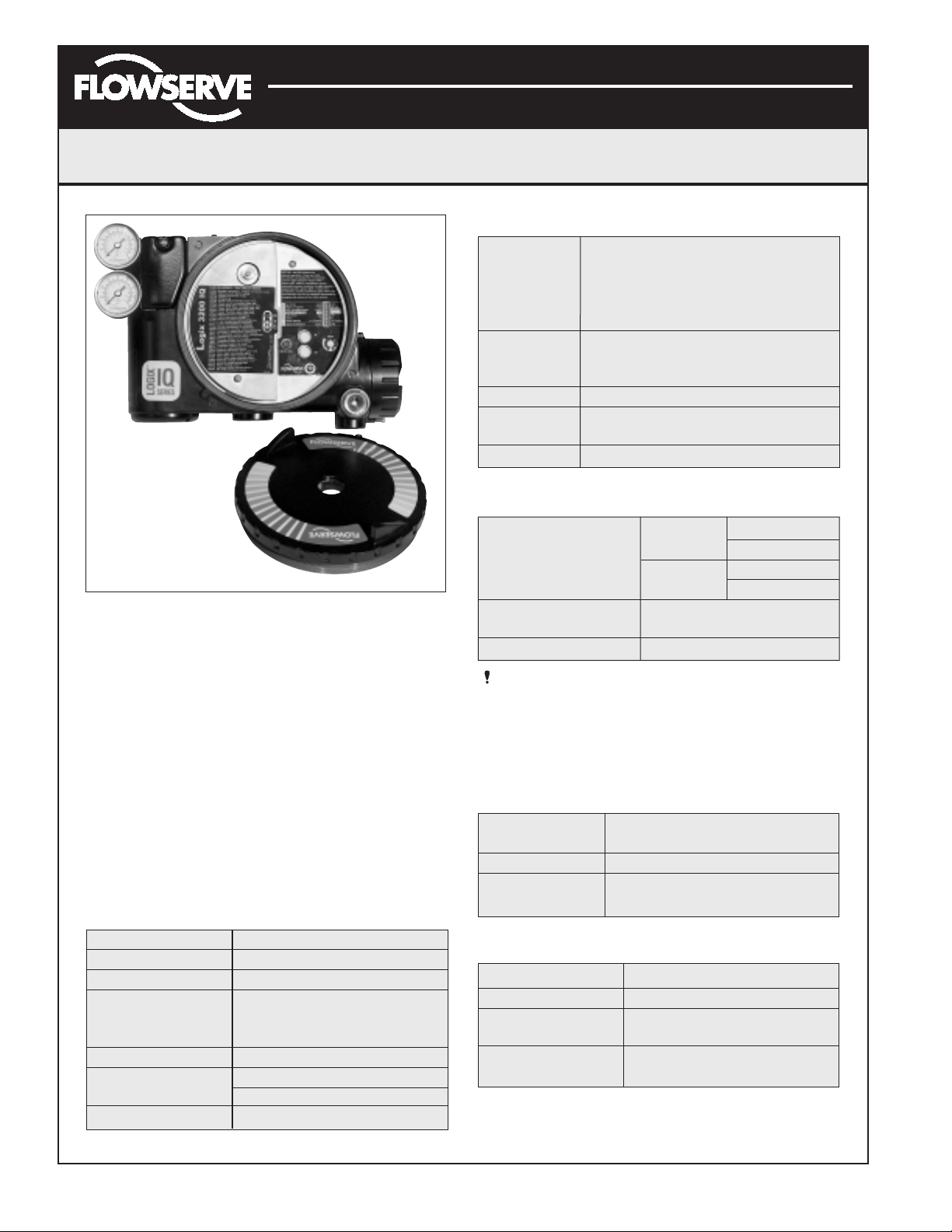
Figure 1: Logix 3200IQ Digital Positioner
Positioner Overview
The Logix 3200IQ digital positioner is a two-wire
4-20 mA input digital valve positioner. The positioner is
configurable through the local user interface. The Logix
3200IQ utilizes the HART protocol to allow two-way
remote communications with the positioner. The Logix
3200IQ positioner can control both double- and singleacting actuators with linear or rotary mountings. The
positioner is completely powered by the 4-20 mA input
signal. Start up current must be at least 3.6 mA without
AO card or 3.85 mA with AO card.
Specifications
Table I: Electrical Specifications
Power Supply Two-wire, 4-20 mA
10.0 to 30.0 VDC
Compliance Voltage 10.0 VDC @ 20 mA
495 Ω @ 20 mA Typical
Effective Resistance Add 20 Ω when HART
communication active
Communications HART Protocol
Minimum Operating 3.6 mA without AO board
Current 3.85 mA with AO board
Maximum Voltage 30.0 VDC
Table II: SoftTools Suite Software Specifications
Computer Minimum Pentium processor running
Windows 95, 98, NT, 2000, XP, 32 MB
total memory (64 MB recommended),
30 MB available hard disk space,
CD-ROM drive
Ports 1 minimum available with 8 maximum
possible. (Can also communicate via
PCMCIA and USB connections)
HART Modem RS-232/PCMCIA card/USB
HART Filter May be required in conjunction with
some DCS hardware
HART MUX MTL 4840/ELCON 2700
Table III: Environmental Conditions
Standard
-4° to 176°F
Operating Temperature (-20° to 80°C)
Range
Low
-40° to 176°F
(-40° to 80°C)
Transport and Storage
Temperature Range
-40° to 176°F (-40° to 80°C)
Operating Humidity 0 to 100% non-condensing
Note: The air supply must conform to ISA Standard
ISA 7.0.01 (a dew point at least 18 degrees Fahrenheit
below ambient temperature, particle size below five
microns – one micron recommended – and oil content
not to exceed one part per million).
Table IV: Physical Specifications
Housing Material Cast, powder-painted aluminum,
stainless steel
Soft Goods Buna-N / Fluorosilicone
Weight
8.3 pounds (3.9 kg) aluminum
20.5 pounds (9.3 kg) stainless steel
Table V: Positioner Specifications
Deadband <0.1% full scale
Repeatability <0.05% full scale
Linearity
<0.5% (rotary), <0.8%,
(sliding stem) full scale
Air Consumption
<0.3 SCFM (0.5 Nm3/hr)
@ 60 psi (4 barg)
Page 3
Flowserve Corporation 1350 N. Mountain Springs Parkway 1978 Foreman Dr.
Flow Control Division Springville, Utah 84663-3004 Cookville, TN 38501
www.flowserve.com Phone: 801 489 2233 Phone: 931 432 4021
FCD AXAIM3200-00 9/04 Page: 3 of 32
© 2004, Flowserve Corporation, Printed in USA
Automax Logix 3200IQ Digital Positioner
Installation, Operation and Maintenance Instructions
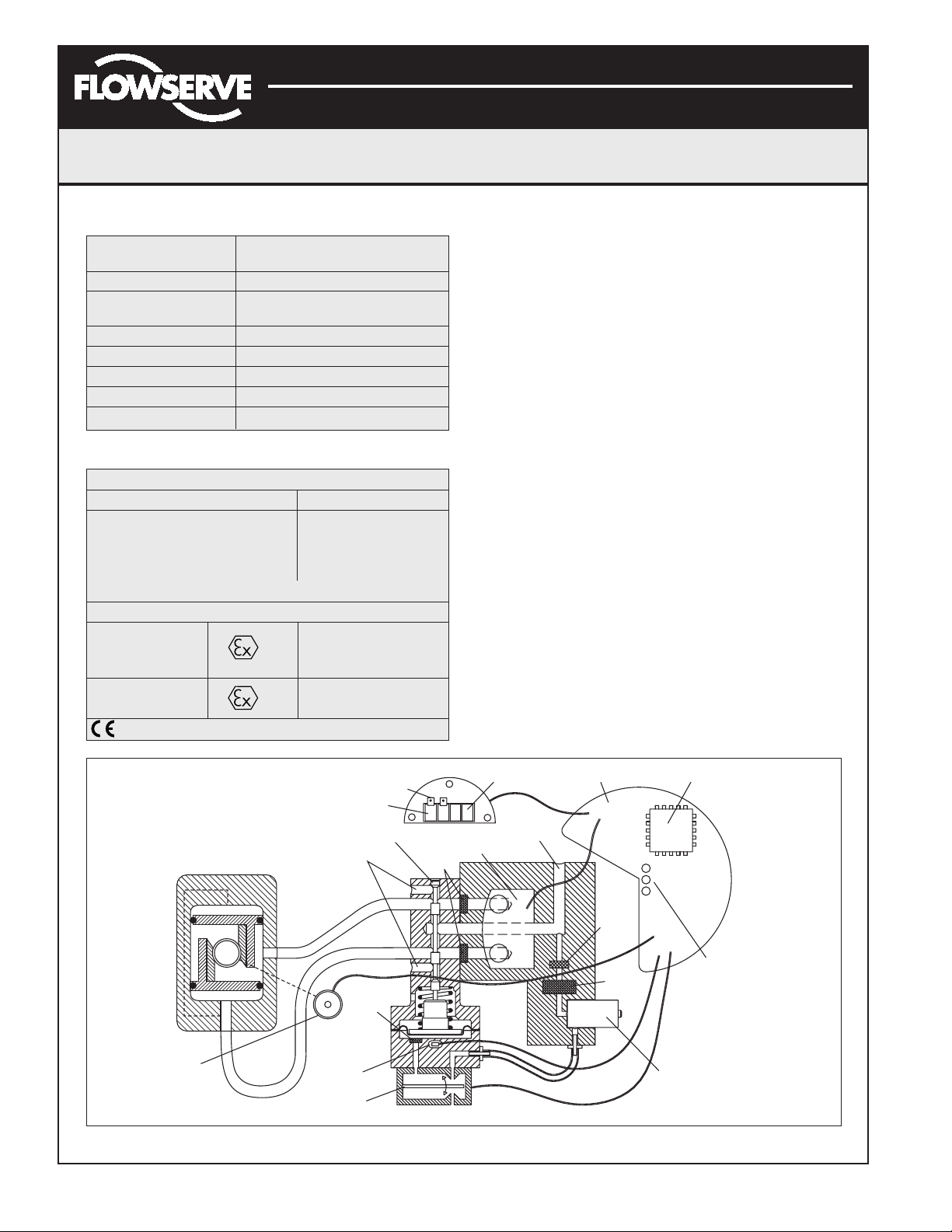
Positioner Operation
The Logix 3200IQ positioner is an electric feedback
instrument. Figure 2 shows a Logix 3200IQ positioner
installed on a double-acting actuator.
The Logix 3200IQ receives power from the two-wire,
4-20 mA input signal. However, since this positioner
utilizes HART communications, two sources can be used
for the command signal: Analog and Digital. In Analog
source, the 4-20 mA signal is used for the command
source. In Digital source, the level of the input 4-20 mA
signal is ignored and a digital signal, sent via HART,
is used as the command source. The command source
selection can be accessed with SoftTools software, the
HART 275/375 communicator, or other host software.
The input signal in percent passes through a
characterization/limits modifier block. The positioner
no longer uses CAMs or other mechanical means to
characterize the output of the positioner. This function
is done in software, which allows for in-the-field
customer adjustment. The positioner has three basic
modes: Linear, Equal Percent (=%) and Custom
characterization. In Linear mode, the input signal is
passed straight through to the control algorithm in a
1:1 transfer. In Equal Percent (=%) mode, the input signal
is mapped to a standard 30:1 rangeability =% curve.
If Custom characterization is enabled, the input signal
is mapped to either a default =% output curve or a
custom, user-defined 21-point output curve. The custom
Figure 2: Logix 3200IQ Digital Positioner Schematic (air-to-open configuration)
Table VI: 4 to 20 mA Analog Output Specifications
Potential Range
40° to 95°
of Rotation
Power Supply Range 12.5 to 40 VDC, (24 VDC typical)
Maximum Load
(Supply voltage - 12.5) / 0.02
Resistance (ohms)
Current Signal Output 4-20 mA
Linearity 1.0% F.S.
Repeatability 0.25% F.S.
Hysteresis 1.0% F.S.
Operating Temperature
-40° to 176°F, -40° to 80°C
Table VII: Hazardous Area Certifications
FM/CSA
Intrinsically Safe Explosion Proof
Class I, Div 1, Groups A, B, C, D
Class I, Div 1,
Groups A, B, C, D
Class II, Div 1, Groups E, F, G
Class II, Div 1,
Groups E, F, G
(See Figure 2 for installation requirements.)
CENELEC
II 1G EEx ia IIC T4, T5
Intrinsically Safe T4 Ta = -40°C to 80°C
T5 Ta = -40°C to 35°C
Flameproof
II 2 GD EEx d IIB + H
2
T5, Ta = -40°C to 80°C
Compliant
Steam
Position
Sensor
Air-to-Open
Configuration
Command
Input Signal
Exhaust
Hall Effect
Sensor
Piezo Valve
Flame
Arrestor
HART
Terminals
Spool Valve
Output 1
Output 2
Flame
Arrestor
Analog Output Signal
Pressure
Sensor Board
Air Supply
Main PCB
Flame
Arrestor
Filter
Digital Position Algorithm
LED
Display
Regulator
Page 4

Flowserve Corporation 1350 N. Mountain Springs Parkway 1978 Foreman Dr.
Flow Control Division Springville, Utah 84663-3004 Cookville, TN 38501
www.flowserve.com Phone: 801 489 2233 Phone: 931 432 4021
FCD AXAIM3200-00 9/04 Page: 4 of 32
© 2004, Flowserve Corporation, Printed in USA
Automax Logix 3200IQ Digital Positioner
Installation, Operation and Maintenance Instructions
user-defined 21-point output curve is defined using a
handheld or PC software. In addition, two user-defined
features, Soft Limits and MPC (Minimum Position Cutoff),
may affect the final input signal. The actual command
being used to position the stem, after any characterization
or user limits have been evaluated, is called the Control
Command.
The Logix 3200IQ uses a two-stage, stem-positioning
algorithm. The two stages consist of an inner-loop,
spool control and an outer-loop, stem position control.
Referring again to Figure 1, a stem position sensor
provides a measurement of the stem movement. The
Control Command is compared against the Stem Position.
If any deviation exists, the control algorithm sends a
signal to the inner-loop control to move the spool up
or down, depending upon the deviation. The inner-loop
then quickly adjusts the spool position. The actuator
pressures change and the stem begins to move. The
stem movement reduces the deviation between Control
Command and Stem Position. This process continues
until the deviation goes to zero.
The inner-loop controls the position of the spool valve
by means of a driver module. The driver module consists
of a temperature-compensated hall effect sensor and a
piezo valve pressure modulator. The piezo valve pressure
modulator controls the air pressure under a diaphragm by
means of a piezo beam bender. The piezo beam deflects
in response to an applied voltage from the inner-loop
electronics. As the voltage to the piezo valve increases,
the piezo beam bends, closing off against a nozzle
causing the pressure under the diaphragm to increase. As
the pressure under the diaphragm increases or decreases,
the spool valve moves up or down respectively. The hall
effect sensor transmits the position of the spool back to
the inner-loop electronics for control purposes.
Detailed Sequence of Positioner Operations
A more detailed example explains the control function.
Assume the unit is configured as follows:
• Unit is in Analog command source.
• Custom characterization is disabled (therefore
characterization is Linear).
• No soft limits enabled. No MPC set.
• Valve has zero deviation with a present input signal
of 12 mA.
• Loop calibration: 4 mA = 0% command, 20 mA =
100% command.
• Actuator is tubed and positioner is configured
air-to-open.
Given these conditions, 12 mA represents a Command
source of 50 percent. Custom characterization is disabled
so the Command source is passed 1:1 to the Control
Command. Since zero deviation exists, the Stem Position
is also at 50 percent. With the stem at the desired
position, the spool valve will be at a middle position that
balances the pressures above and below the piston in the
actuator. This is commonly called the null or balanced
spool position.
Assume the input signal changes from 12 mA to 16 mA.
The positioner sees this as a Command source of 75
percent. With Linear characterization, the Control
Command becomes 75 percent. Deviation is the difference
between Control Command and Stem Position: Deviation
= 75% - 50% = +25%, where 50 percent is the present
stem position. With this positive deviation, the control
algorithm sends a signal to move the spool up from its
present position. As the spool moves up, the supply air is
applied to the bottom of the actuator and air is exhausted
from the top of the actuator. This new pressure differential
causes the stem to start moving towards the desired
position of 75 percent. As the stem moves, the Deviation
begins to decrease. The control algorithm begins to
reduce the spool opening. This process continues until
the Deviation goes to zero. At this point, the spool will be
back in its null or balanced position. Stem movement will
stop and the desired stem position is now achieved.
One important parameter has not been discussed to this
point: Inner loop offset. Referring to Figure 3, a number
called Inner loop offset is added to the output of the
control algorithm. In order for the spool to remain in its
null or balanced position, the control algorithm must
output a non-zero spool command. This is the purpose
of the Inner loop offset. The value of this number is
equivalent to the signal that must be sent to the spool
position control to bring it to a null position with zero
deviation. This parameter is important for proper control
and is optimized and set automatically during stroke
calibration.
Page 5
Flowserve Corporation 1350 N. Mountain Springs Parkway 1978 Foreman Dr.
Flow Control Division Springville, Utah 84663-3004 Cookville, TN 38501
www.flowserve.com Phone: 801 489 2233 Phone: 931 432 4021
FCD AXAIM3200-00 9/04 Page: 5 of 32
© 2004, Flowserve Corporation, Printed in USA
Automax Logix 3200IQ Digital Positioner
Installation, Operation and Maintenance Instructions
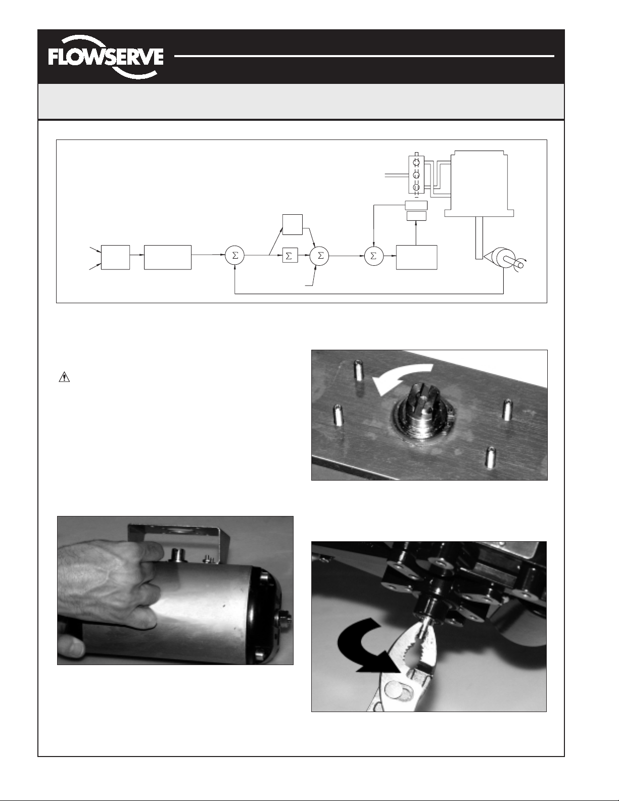
Mounting the Positioner
CAUTION: Positioner shaft is spring-loaded and
features mechanical stops at each end of stroke.
Failure to follow these procedures carefully may
result in severe damage to positioner. Read through
entire procedure before starting.
1. Attach positioner mounting bracket to actuator using
fasteners supplied with bracket (Figure 4). Tighten
bolts finger-tight only at this time.
2. Install coupler (if required – coupler is not required
for NAMUR mounting) on actuator shaft, making sure
it is centered.
Figure 4: Linear Mark One Control Valve Mounting
3. Stroke the actuator to determine direction of rotation
as shown in Figure 5. Pay specific attention to the slot
that will engage positioner shaft.
Figure 5: Actuator Shaft
4. Carefully grasp positioner shaft with pliers as shown in
Figure 6. Turn shaft to determine direction of rotation.
Figure 6: Turn Positioner Shaft
Figure 3: System Positioning Algorithm
Air
4-20 mA
(Analog
Mode)
Command In
(Digital
Mode)
Input
Signal
Analog
Digital
Linear Mode
Characterization
Soft Limits
MPC
Control
Algorithm
Pmax
Pmin
Gmult
CONTROL
COMMAND
Deviation
+
–
Integration
Summer
I
Inner
Loop
Offset
+
+
+
D/A
Output
Percentage
Inner-Loop
Output
Supply
+
Sensor
Piezo
Valve
Voltage
–
Inner
Loop
Spool
Control
Tubed
ATO
Stem
Position
Sensor
Page 6
Flowserve Corporation 1350 N. Mountain Springs Parkway 1978 Foreman Dr.
Flow Control Division Springville, Utah 84663-3004 Cookville, TN 38501
www.flowserve.com Phone: 801 489 2233 Phone: 931 432 4021
FCD AXAIM3200-00 9/04 Page: 6 of 32
© 2004, Flowserve Corporation, Printed in USA
Automax Logix 3200IQ Digital Positioner
Installation, Operation and Maintenance Instructions
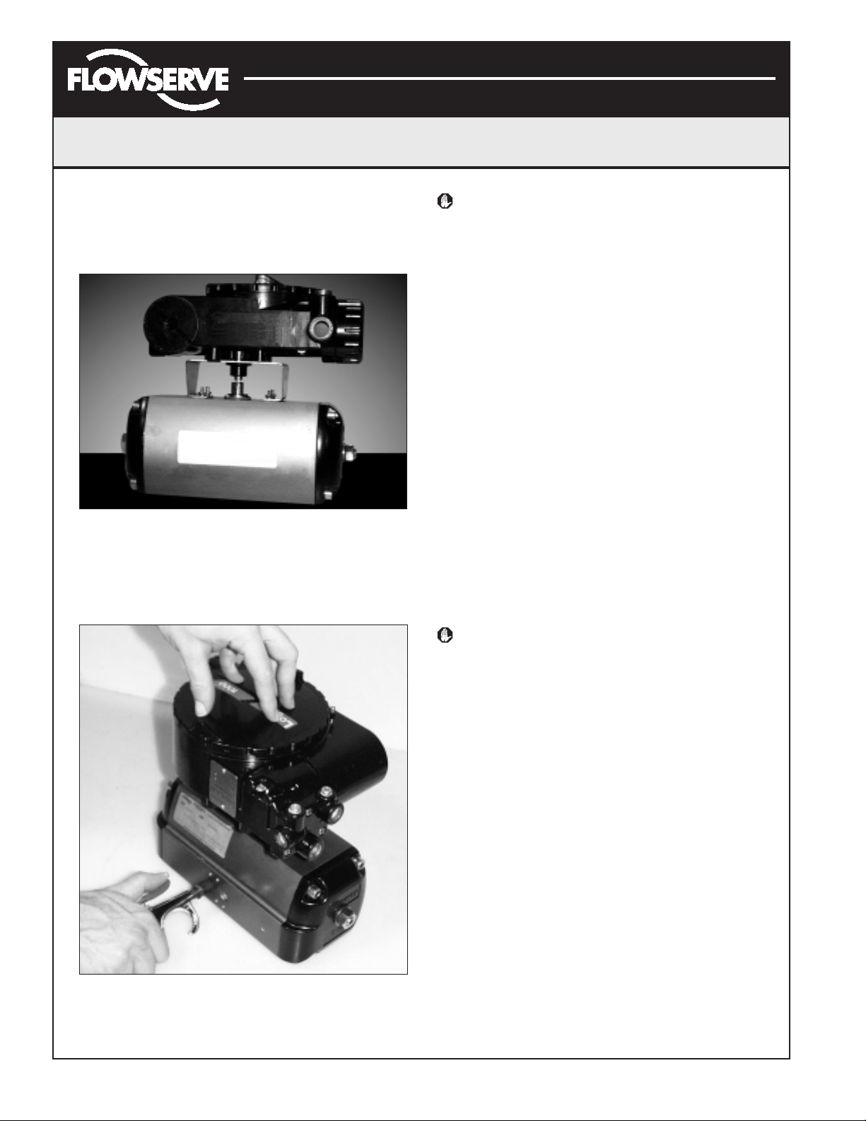
5. Making sure positioner shaft rotation matches actuator
shaft rotation, place positioner on mounting bracket
(Figure 7). Make sure shafts engage. Do not insert
fasteners into positioner at this time.
Figure 7: Positioner on Mounting Bracket
6. Double-check actuator and positioner rotation. Hold
positioner against bracket with fingertips as shown in
Figure 8.
Figure 8: Check Positioner Shaft Alignment
WARNING: Keep away from positioner sides, as
positioner will suddenly rotate on bracket if not
properly aligned and cause injury.
Slowly rotate the actuator. If the positioner shaft is
properly aligned, the shaft will rotate freely. If not, the
mechanical stops will grab, causing the positioner body
to rotate on bracket.
7. If the shaft is not properly aligned, repeat steps 3-6.
Otherwise, attach positioner to bracket with fasteners
included with bracket. Tighten bolts finger-tight only at
this time.
8. Stroke actuator/positioner several times to align shafts.
Tighten all fasteners.
Tubing Positioner to Actuator
Proper tubing orientation is critical for the positioner to
function correctly and have the proper failure mode. Referring
to Figure 2, note that for air-to-open valves, the Output 1 port
of the positioner manifold is tubed to the ‘open’ side of the
actuator. The Output 2 port of the positioner manifold is tubed
to the ‘closed’ side of the actuator. For air-to-close valves the
above configuration is reversed.
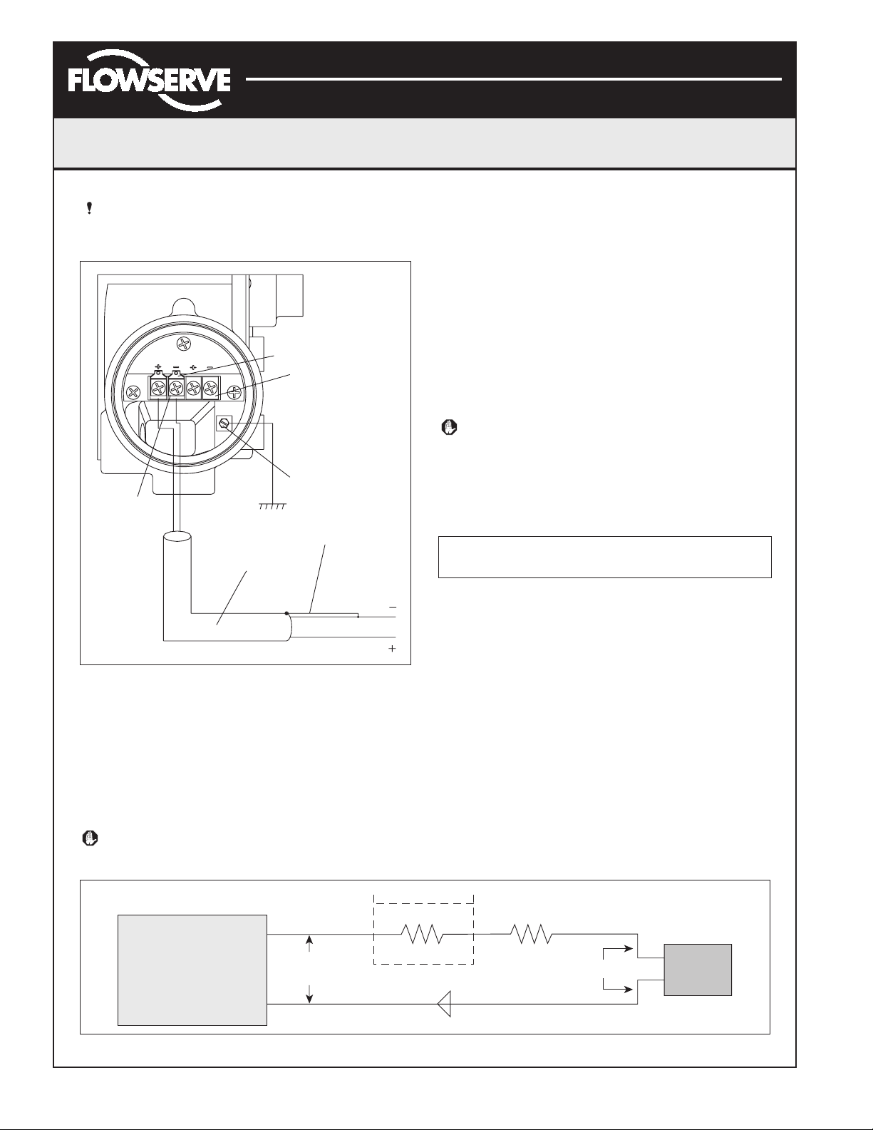
Wiring and Grounding Guidelines
(See Figure 9)
WARNING: This product has electrical conduit
connections in either thread sizes 1/2" NPT or M20
which appear identical but are not interchangeable.
Housings with M20 threads are stamped with the
letters M20 above the conduit opening. Forcing
dissimilar threads together will damage equipment,
cause personal injury and void hazardous location
certifications. Conduit fittings must match
equipment housing threads before installation.
If threads do not match, obtain suitable adapters
or contact a Flowserve representative.
4-20 mA Command Input Wiring
Verify polarity when making field termination connection.
The Logix 3200 is reverse polarity protected. Wire 4-20
mA current source to the input terminal labeled 4-20 mA
Input on the user interface board (see Figure 9). Never
connect a voltage source directly across the Logix 3200IQ
terminals. The current must always be limited for 4-20
mA operation. Minimum operating current is 3.6 mA.
The input loop current signal to the Logix 3200IQ digital
positioner should be in shielded cable. Shields must be
tied to a ground at only one end of the cable to provide
a place for environmental electrical noise to be removed
from the cable. In general, shield wire should be
connected at the source.
Page 7
Flowserve Corporation 1350 N. Mountain Springs Parkway 1978 Foreman Dr.
Flow Control Division Springville, Utah 84663-3004 Cookville, TN 38501
www.flowserve.com Phone: 801 489 2233 Phone: 931 432 4021
FCD AXAIM3200-00 9/04 Page: 7 of 32
© 2004, Flowserve Corporation, Printed in USA
Automax Logix 3200IQ Digital Positioner
Installation, Operation and Maintenance Instructions
NOTE: The Logix 3200IQ positioner carries an
intrinsically safe barrier rating of 100 mA. Input
currents should not exceed 100 mA.
Figure 9: Field Termination
Grounding Screw
The green grounding screw, located inside the termination
cap, should be used to provide the unit with an adequate
and reliable earth ground reference. This ground should
be tied to the same ground as the electrical conduit.
Additionally, the electrical conduit should be earth
grounded at both ends of its run.
WARNING: The green grounding screw must not be
used to terminate signal shield wires.
Compliance Voltage (See Figure 10)
Output compliance voltage refers to the voltage limit that
can be provided by the current source. A current loop
system consists of the current source, wiring resistance,
barrier resistance (if present), and the Logix 3200IQ
positioner impedance. The Logix 3200IQ digital positioner
requires that the current loop system allows for a 10.0
VDC drop across the positioner at maximum loop current.
The 10.0 VDC drop across the Logix 3200IQ positioner
terminals is generated by the positioner from the 4-20 mA
loop current input. The actual voltage at the terminals
varies from 9.8 to 10.0 VDC depending on the current mA
signal, HART communications and ambient temperature.
WARNING: Never connect a voltage source directly
across the positioner terminals. This could cause
permanent circuit board damage.
Determine if the loop will support the Logix 3200IQ digital
positioner by performing the following calculation.
Equation 1
Voltage = Compliance Voltage (@Current
max
) –
Current
max
• (R
barrier+Rwire
)
The calculated voltage must be greater than 10 VDC in
order to safely support the Logix 3200IQ digital
positioner.
Example:
DCS Compliance Voltage = 19 VDC
R
barrier
= 300 Ω
R
wire
= 25 Ω
Current
max
= 20 mA
Voltage = 19 VDC – 0.020 A • (300 Ω + 25 Ω) = 12.5 VDC
The voltage 12.5 VDC is greater than the required
10.0 VDC; therefore, this system will support the Logix
3200IQ digital positioner. The Logix 3200IQ positioner
has a worst case input resistance equivalent to 500 Ω
at a 20 mA input current.
Figure 10: Compliance Voltage
ANALOG
Field
T
erminators
HART
4-20 mA INPUT
OUTPUT
HART Terminals
4-20 mA Feedback
Terminals (Optional)
Housing EARTH
Terminal
Connect Shield at Source
Ground 4-20 mA Current Source
Shielded Cable
4-20 mA Current Source
If Present
R
Wire
10 VDC
+
Logix
3200IQ
–
Current
Source
Compliance
Voltage
R
Barrier
Current
Page 8
Flowserve Corporation 1350 N. Mountain Springs Parkway 1978 Foreman Dr.
Flow Control Division Springville, Utah 84663-3004 Cookville, TN 38501
www.flowserve.com Phone: 801 489 2233 Phone: 931 432 4021
FCD AXAIM3200-00 9/04 Page: 8 of 32
© 2004, Flowserve Corporation, Printed in USA
Automax Logix 3200IQ Digital Positioner
Installation, Operation and Maintenance Instructions
Cable Requirements
The Logix 3200IQ digital positioner utilizes the HART
Communication protocol. This communication signal is
superimposed on the 4-20 mA current signal. The two
frequencies used by the HART protocol are 1200 Hz and
2200 Hz. In order to prevent distortion of the HART
communication signal, cable capacitance and cable length
restrictions must be calculated. The cable length must be
limited if the capacitance is too high. Selecting a cable
with lower capacitance/foot rating will allow longer cable
runs. In addition to the cable capacitance, the network
resistance also affects the allowable cable length.
In order to calculate the maximum network capacitance,
use the following formula:
Equation 2
To control cable resistance, 24 AWG cable should be used
for runs less than 5000 feet. For cable runs longer than
5000 feet, 20 AWG cable should be used.
Intrinsically Safe Barriers
When selecting an intrinsically safe barrier, make sure the
barrier is HART compatible. Although the barrier will pass
the loop current and allow normal positioner control, if
not compatible, it may prevent HART communication.
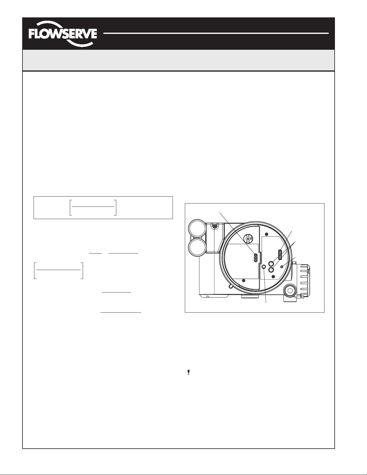
Startup
Logix 3200IQ Local Interface Operation
The Logix 3200IQ local user interface (Figure 11) allows
the user to configure the basic operation of the positioner,
tune the response and calibrate the positioner without
additional tools or configurators. The Local interface
consists of a QUICK-CAL button for automatic zero and
span setting, along with two jog buttons (↑ and ↓) for
spanning valve/actuators with no fixed internal stop in the
open position. There is also a DIP switch block containing
eight switches. Seven of the switches are for basic
configuration settings and one is for calibration options.
There is also a rotary selector switch for adjusting the
positioner gain settings. For indication of the operational
status or alarm conditions there are also three LEDs on
the local user interface.
Figure 11: Local User Interface
Initial DIP Switch Settings
Before placing the unit in service, set the DIP switches in
the Configuration and Cal boxes to the desired control
options. A detailed description of each DIP switch setting
follows.
NOTE: The Logix 3200IQ positioner reads the DIP
switch settings each time the QUICK-CAL button is
pressed. If a HART handheld or Flowserve PC software
is used to configure and then calibrate the positioner,
the DIP switches are not read. The auto-tune
adjustment switch labeled “GAIN” is always live and
can be adjusted at any time.
C
(µF) ≤ - 0.0032
network
Example: R
(R
barrie r
R
wire
C
cable
65
+ R
barrier
wire
= 300 Ω
= 50 Ω
22 pF
= =
t
foo
+ 390)
0.000022 µF
foot
65
(300 + 50 + 390
- 0.0032 = 0.08 µF = C
)
max network
(µf)
LEDs
DIP Switch Block
Jog Buttons
Rotary
Selector
Switch
C
Maximum Cable Length
Maximum Cable Length
=
= = 3636 ft
0.000022 µF/foo
max network
C
cable
0.08 µF
(µF)
QUICK-CAL Button
t
Page 9
Flowserve Corporation 1350 N. Mountain Springs Parkway 1978 Foreman Dr.
Flow Control Division Springville, Utah 84663-3004 Cookville, TN 38501
www.flowserve.com Phone: 801 489 2233 Phone: 931 432 4021
FCD AXAIM3200-00 9/04 Page: 9 of 32
© 2004, Flowserve Corporation, Printed in USA
Automax Logix 3200IQ Digital Positioner
Installation, Operation and Maintenance Instructions
Description of Configuration DIP Switch Settings
The first seven DIP switches are for basic configuration.
The function of each switch is described below.
Air Action
This must be set to match the configuration of the
valve/actuator mechanical tubing connection and spring
location since these determine the air action of the
system.
ATO (air-to-open) – Selecting ATO if increasing output
pressure from the positioner is tubed so it will cause the
valve to open.
ATC (air-to-close) – Selecting ATC if increasing output
pressure from the positioner is tubed so it will cause the
valve to close.
Signal at Closed
Normally this will be set to 4 mA for an Air-to-open
actuator and 20 mA for an Air-to-close actuator
configuration.
4 mA – Selecting 4 mA will make the valve fully closed
when the signal is 4 mA and fully open when the signal
is 20 mA.
20 mA – Selecting 20 mA will make the valve fully
closed when the signal is 20 mA and fully open when
the signal is 4 mA.
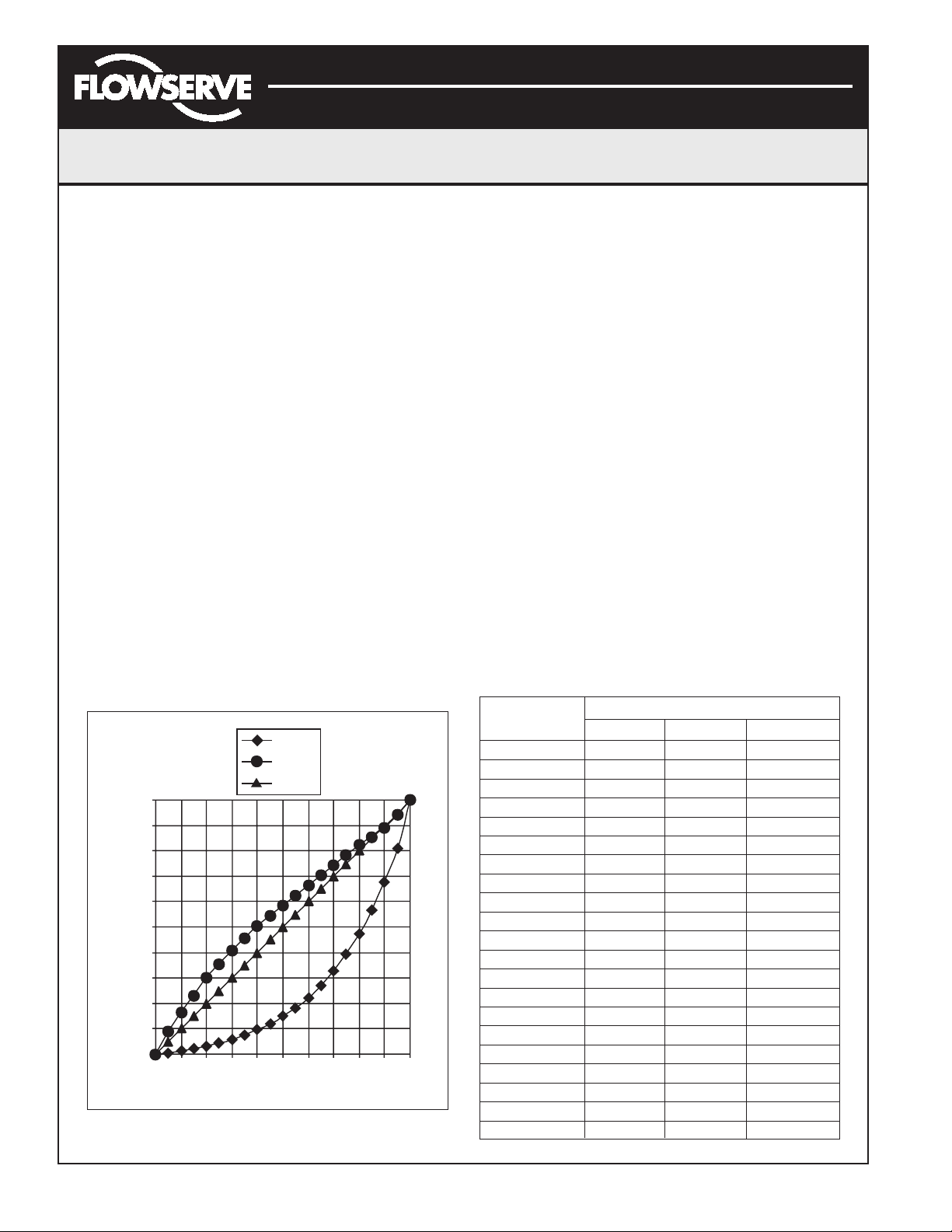
Figure 12: Default Custom Characterization
Pos. Characterization
Linear – Select Linear if the actuator position should be
directly proportional to the input signal.
Optional – Select Optional if another characteristic is
desired, which is set in conjunction with the next switch,
labeled Optional Pos. Char.
Optional Pos. Characterization
If the Pos. Characterization switch is set to optional then
this switch is active with the following options:
=% – The =% option will characterize the actuator
response to the input signal based on a standard 30:1
equal percent rangeability curve.
Custom – If Custom is selected, the positioner will be
characterized to a custom table that must be set-up
using a properly configured HART 275/375 handheld or
other host software. Custom characterization can be
thought of as a “soft CAM.” The user can define a
characterization curve using 21 points. The control will
linearly interpolate between points. Points do not have
to be equally spaced in order to allow more definition at
critical curve areas. The default values will linearize the
output of a valve with an inherent =% characteristic
(e.g., ball valves).
Table VIII: Characteristic Curve Data
% Command
% Control Command
=% Linear Custom
00 00
5 0.62 5 8.66
10 1.35 10 16.24
15 2.22 15 23.17
20 3.25 20 30.11
25 4.47 25 35.31
30 5.91 30 40.51
35 7.63 35 45.42
40 9.66 40 50.34
45 12.07 45 54.40
50 14.92 50 58.47
55 18.31 55 62.39
60 22.32 60 66.31
65 27.08 65 70.27
70 32.71 70 74.23
75 39.40 75 78.17
80 47.32 80 82.11
85 56.71 85 85.50
90 67.84 90 88.89
95 81.03 95 94.45
100 100.00 100 100.00
=%
Custom
Linear
100
90
80
70
60
50
40
% Control Command
30
20
10
0
0 102030405060708090100
% Command
Page 10
Flowserve Corporation 1350 N. Mountain Springs Parkway 1978 Foreman Dr.
Flow Control Division Springville, Utah 84663-3004 Cookville, TN 38501
www.flowserve.com Phone: 801 489 2233 Phone: 931 432 4021
FCD AXAIM3200-00 9/04 Page: 10 of 32
© 2004, Flowserve Corporation, Printed in USA
Automax Logix 3200IQ Digital Positioner
Installation, Operation and Maintenance Instructions
Auto Tune
This switch controls whether the positioner will auto tune
itself every time the QUICK-CAL button is pressed or use
preset tuning parameters.
On – On enables an auto tune feature that will
automatically determine the positioner gain settings
based on the current position of the adjustable GAIN
switch setting and response parameters measured
during the last QUICK-CAL. The GAIN switch is live,
meaning the settings can be adjusted at any time by
changing the rotary switch position. (Note that there is a
small black arrow indicating the selection. The slot in
the switch is NOT the indicator.)
Figure 13: Adjustable GAIN Switch
If the adjustable GAIN selector switch is set to “E”
with the auto tune switch on, a Flowserve standard
response tuning set will be calculated and used based
on response parameters measured during the last
QUICK-CAL.
If the adjustable GAIN selector switch is set to “D”, “C”,
“B”, or “A” with the auto tune switch on, progressively
lower gain settings will be used based on response
parameters measured during the last QUICK-CAL.
If the adjustable GAIN selector switch is set to “F”,
“G”, or “H” with the auto tune switch on, progressively
higher gain settings will be calculated and used based
on response parameters measured during the last
QUICK-CAL.
Off – Off forces the positioner to use one of the factory
preset tuning sets determined by the adjustable GAIN
selector switch. Settings “A” through “H” are progressively higher gain predefined tuning sets. The GAIN
selector switch is live and can be adjusted at any time
to modify the tuning parameters.
NOTE: “E” is the default adjustable GAIN selector
switch setting for all actuator sizes. Raising or
lowering the gain setting is a function of the
positioner/valve response to the control signal,
and is not actuator size dependent.
Configuration Switches
Enabled – By selecting Enabled, the Logix 3200IQ
will read all of the configuration switches each time a
QUICK-CAL is performed to determine the configuration.
Disabled – Selecting Disabled retains the last
configuration in memory (from the last successful
calibration) before the switch was set to Disabled.
With this setting a QUICK-CAL only zeros and spans
the positioner.
Stability Switch
This switch adjusts the position control algorithm of
the positioner for use with low-friction control valves
or high-friction automated valves.
Low-Friction Valves – Placing the switch to the
left optimizes the response for low-friction, highperformance control valves. This setting provides
for optimum response times when used with most
low-friction control valves.
High-Friction Valves – Placing the switch to the right
optimizes the response for valves and actuators with
high friction levels. This setting slightly slows the
response and will normally stop limit cycling that can
occur on high-friction valves.
Description of Cal DIP Switch Settings
The eighth DIP switch selects between two calibration
options. The function of the Cal DIP switch is described
below.
Auto – Select Auto if the valve/actuator assembly has
an internal stop in the open position. In Auto mode the
positioner will fully close the valve and register the 0%
position and then open the valve to the stop to register
the 100% position when performing a self-calibration.
See detailed instructions in the next section on how to
perform an auto positioner calibration.
Jog – Select Jog if the valve/actuator assembly has no
physical calibration stop in the open position. In the
Jog mode the positioner will fully close the valve for the
0% position and then wait for the user to set the open
position using the Jog buttons labeled with the up and
down arrows. See the detailed instructions in the next
section on how to perform a manual calibration using
the Jog buttons.
WARNING: During the QUICK-CAL operation the
valve may stroke unexpectedly. Notify proper
personnel that the valve will stroke and make
sure the valve is properly isolated.
GAIN
A
B
H
G
F
C
D
E
Page 11

Flowserve Corporation 1350 N. Mountain Springs Parkway 1978 Foreman Dr.
Flow Control Division Springville, Utah 84663-3004 Cookville, TN 38501
www.flowserve.com Phone: 801 489 2233 Phone: 931 432 4021
FCD AXAIM3200-00 9/04 Page: 11 of 32
© 2004, Flowserve Corporation, Printed in USA
Automax Logix 3200IQ Digital Positioner
Installation, Operation and Maintenance Instructions
QUICK-CAL Operation
The QUICK-CAL button is used to locally initiate a
calibration of the positioner. Pressing and holding the
QUICK-CAL button for approximately three seconds will
initiate the calibration. If the Config-Switches option is
enabled, the settings of all the configuration switches
are read and the operation of the positioner adjusted
accordingly. A QUICK-CAL can be aborted at any time by
briefly pressing the QUICK-CAL button and the previous
settings will be retained.
If the Quick Calibration switch (be careful not to confuse
this with the QUICK-CAL button) is set to Auto and the
valve/actuator assembly has the necessary internal stops
the calibration will complete automatically. While the
calibration is in progress you will notice a series of
different lights flashing indicating the calibration progress.
When the lights return to a sequence that starts with a
green light the calibration is complete. An explanation of
the various light sequences follows. The initial calibration
of extremely large or small actuators may require several
calibration attempts. The positioner adapts to the actuator
performance and begins each calibration where the last
attempt ended. On an initial installation it is recommended
that after the first successful calibration that one more
calibration be completed for optimum performance.
WARNING: When operating using QUICK-CAL or
local control, the valve will not respond to external
commands. Notify proper personnel that the valve
will not respond to remote command changes
and make sure the valve is properly isolated.
Manual Jog Calibration Operation
If the Quick Calibration switch is set to Jog, the calibration
will initially close the valve then cause a small jump in the
valve position. The jog calibration process will only allow
the user to manually set the span; zero position is
automatically always set at the seat. If an elevated zero
is needed a handheld or other PC based configuration
software is required. When performing a jog calibration,
the LEDs will flash in a sequence of Y-R-R-G (yellow-redred-green) which indicates that the user must use the
Jog buttons (↑ and ↓) to manually position the valve to
approximately 100%. When the valve is approximately
100% open press both the Jog buttons (↑ and ↓)
simultaneously to proceed to the next step. The valve will
stroke and then wait while flashing the Y-R-R-G sequence
again, allowing the user to adjust the valve position a
second time to exactly 100% using the Jog buttons
(↑ and ↓). When the stem is properly positioned press
both the Jog buttons (↑ and ↓) simultaneously again to
register the 100% position and proceed. No more user
actions are required while the calibration process is
completed. When the lights return to a sequence that
starts with a green light the calibration is complete.
An explanation of the various light sequences follows.
Local Control of Valve Position
Local control of valve position can be achieved from the
user interface by holding down both Jog buttons and the
QUICK-CAL button simultaneously for three seconds.
While in this mode the LEDs will flash a YGRR (yellowgreen-red-red) sequence. Use the two Jog buttons
(↑ and ↓) to manually control the position of the valve.
To exit the local control mode and return to normal
operation, briefly press the QUICK-CAL button.
Factory Reset
To perform a factory reset, disconnect power, hold the
QUICK-CAL button down and reconnect power.
Performing a factory reset will cause all of the internal
variables, including calibration, to be reset to factory
defaults. The positioner must be recalibrated after a
factory reset. Tag names and other user configured limits,
alarm settings and valve information will also need to
be restored.
WARNING: Performing a factory reset may result in
the inability to operate the valve until reconfigured
properly. Notify proper personnel that the valve may
stroke and make sure the valve is properly isolated.
Command Source Reset
Performing a command source reset will reset the
command source to analog source if it has been
inadvertently left in digital mode. This is done while a
QUICK-CAL is in process by holding down both the Jog
buttons (↑ and ↓) while briefly pressing the QUICK-CAL
button. A new QUICK-CAL must be done after resetting.
Logix 3200IQ Status Condition
The blink codes used to convey the status of the Logix
3200IQ digital positioner are described in the table below.
In general, any sequence starting with a green light
flashing first is a normal operating mode and indicates
that there are no internal problems. Any sequence starting
with a yellow light flashing indicates that the unit is in a
special calibration or test mode, or that there was a
calibration problem. Any sequence starting with a red light
flashing indicates that there is an operational problem
with the unit.
Page 12

Colors ID Indication and Resolution
Flowserve Corporation 1350 N. Mountain Springs Parkway 1978 Foreman Dr.
Flow Control Division Springville, Utah 84663-3004 Cookville, TN 38501
www.flowserve.com Phone: 801 489 2233 Phone: 931 432 4021
FCD AXAIM3200-00 9/04 Page: 12 of 32
© 2004, Flowserve Corporation, Printed in USA
Automax Logix 3200IQ Digital Positioner
Installation, Operation and Maintenance Instructions
Logix 3200IQ Status Condition Codes
Colors ID Indication and Resolution
G - - - Any sequence starting with a green light flashing first is a
normal operating mode and indicates that there are no
internal problems.
GGGG 1 Normal operation - Analog Command mode. No errors,
alerts, or warnings.
GGGY 2 Tight shutoff (MPC) active - The command is below the
user-set limit for tight shutoff feature. This is a normal
condition for a closed valve. The factory default setting is
1% command. To clear the condition use handheld or
Flowserve-supplied software to reset the tight shutoff if the
range is incorrect or adjust the command signal above the
specified MPC value.
GGYG 3 Digital command mode - The analog 4-20 mA input signal
is ignored in this mode and a handheld or Flowservesupplied software is needed to change the position
command. (Note a command reset is provided to change
the command back to analog control mode from the local
interface if a PC or handheld configurator is not available.)
GGYR 4 Initializing - This sequence should only be visible for three
sequences when powering up the unit.
GGRG 5 Cycle limit exceeded (user-set) - The cycle limit set by the
user has been exceeded. To clear use handheld or
Flowserve-supplied software to reset.
GGRY 6 Travel limit exceeded (user-set) - The total accumulated
travel limit set by the user has been exceeded. To clear use
handheld or Flowserve-supplied software to reset.
GYYR 7 Lower soft stop reached (user-set) - The unit is being
commanded to exceed a user-defined lower position limit
and the internal software is holding the position at the limit.
The function is similar to a mechanical limit stop except it is
not active if the unit is un-powered. To clear the condition
use handheld or Flowserve-supplied software to reset the
limit if more travel is needed or adjust the command signal
back in the specified range.
GYRY 8 Upper soft stop reached (user-set) - The unit is being
commanded to exceed a user-defined upper position limit
and the internal software is holding the position at the limit.
The function is similar to a mechanical limit stop except it is
not active if the unit is un-powered. To clear the condition
use handheld or Flowserve-supplied software to reset the
limit if more travel is needed or adjust the command signal
back in the specified range.
GRYR 9 Lower position alert (user-set) - The position has reached
or is exceeding a user-defined lower position indicator
similar to a limit switch indicator. To clear the condition use
handheld or Flowserve-supplied software to reset the
indicator if more travel is needed or adjust the command
signal back in the specified range.
GRRY 10 Upper position alert (user-set) - The position has reached
or is exceeding a user-defined upper position indicator
similar to a limit switch indicator. To clear the condition use
handheld or Flowserve-supplied software to reset the
indicator if more travel is needed or adjust the command
signal back in the specified range.
Y - - - Any sequence starting with a yellow light indicates that the
unit is in a special calibration or test mode, or that there
was a calibration problem.
YGYG 11 Signature test in progress - This is a test initiated by
Flowserve-supplied software that can only be cancelled by
that software.
YYYG 12 Loop calibration in progress - Calibration sequence
controlled by a handheld or Flowserve-supplied software
that can only be cancelled by that software.
YRGG 13 Stroke calibration in progress - Calibration sequence
started either using the local QUICK-CAL button or by a
handheld or Flowserve-supplied software. It may be
cancelled by briefly pushing the QUICK-CAL button.
YGRR 14 Local jog control model - The unit has been placed in a
local override mode where the valve can only be stroked
using the two local jog buttons. It may be cancelled by
briefly pushing the QUICK-CAL button.
YYGR 15 Pressure calibration in progress - Calibration sequence
controlled by a handheld or Flowserve-supplied software
that can only be cancelled by that software.
YYYY 16 Local user interface disabled - PC software has been used
to disable the local interface. If local control is desired then
the local interface must be re-enabled from the remote
software. This code is only present for a short time when
the QUICK-CAL button is pressed.
YRRG 17 Waiting - Adjust to full open position setting from
User — only used during Jog calibration see explanation
on page 11, “QUICK-CAL,” for operation.
YRYG 18 Setting IL offset while calibrating - An automatic step in
the calibration process that is done with the valve at 50%
position. This must be completed for proper calibration.
YRYY 19 No feedback motion while calibrating - Indicates that there
was no motion of the actuator based on the current stroke
time configuration. Check linkages and air supply to make
sure the system is properly connected. If the time out
occurred because the actuator is very large then simply
retry the QUICK-CAL and the positioner will automatically
adjust for a larger actuator by doubling the time allowed for
movement. This error may be cleared by briefly pushing the
QUICK-CAL button, which will force the positioner to use
the parameters from the last good calibration.
YRYR 20 Feedback 0% out of range - Calibration error indicating that
the position sensor was out of range during the calibration
of the closed position. To correct the condition, adjust the
positioner mounting, linkage or feedback potentiometer to
move the position sensor back into range then restart the
calibration. This error may be cleared by briefly pushing the
QUICK-CAL button, which will force the positioner to use
the parameters from the last good calibration.
YRRY 21 Feedback 100% out of range - Calibration error indicating
that the position sensor was out of range during the
calibration of the open position. To correct the condition,
adjust the positioner mounting, linkage or feedback
potentiometer to move the position sensor back into range
then restart the calibration. This error may be cleared by
briefly pushing the QUICK-CAL button, which will force the
positioner to use the parameters from the last good
calibration.
YRRR 22 Feedback span too small - The range of motion of the
position feedback arm was too small for optimum
performance. Check for loose linkages and/or adjust the
feedback pin to a position closer to the follower arm pivot
to create a larger angle of rotation and recalibrate. Briefly
pushing the QUICK-CAL button acknowledges this condition
and the positioner will operate using the current short
stroke calibration if otherwise a good calibration.
YRGR 23 Feedback unstable while calibrating - Check for loose
linkages or loose positioner sensor. This error may be
cleared by briefly pushing the QUICK-CAL button, which will
force the positioner to use the parameters from the last
good calibration. This error may appear on some very small
actuators during the initial calibration. Redoing the
calibration may clear the problem.
Page 13

Colors ID Indication and Resolution
Flowserve Corporation 1350 N. Mountain Springs Parkway 1978 Foreman Dr.
Flow Control Division Springville, Utah 84663-3004 Cookville, TN 38501
www.flowserve.com Phone: 801 489 2233 Phone: 931 432 4021
FCD AXAIM3200-00 9/04 Page: 13 of 32
© 2004, Flowserve Corporation, Printed in USA
Automax Logix 3200IQ Digital Positioner
Installation, Operation and Maintenance Instructions
R - - - Any sequence starting with a red light indicates that there is
an operational problem with the unit.
RGRR 24 Position deviation (user-set) - The position has exceeded
user-defined error band between command and position.
RGYY 25 Pressure reading out of range - The internal pressure
sensors are either saturated with a pressure over 150 psi or
the sensor has failed. Check supply pressure and if OK
check the pressure sensor board connections and replace
pressure sensor board if necessary.
RGYR 26 Loss of supply pressure - The positioner has determined
that the supply pressure is below 15 psi. Check the supply
pressure and if OK check the pressure sensor board
connections and replace pressure sensor board if
necessary. Minimum recommended supply pressure is
30 psi for proper operation.
RYYY 27 Pilot relay non-motion alert - Check to make sure the air
supply is connected. Also check the internal wiring
harnesses for good connections. This error may be cleared
by briefly pushing the QUICK-CAL button, which will force
the positioner to use the parameters from the last good
calibration. If the positioner still does not operate replace
the pneumatic relay assembly.
RYYR 28 Pilot relay lower position alert - Check to make sure the
air supply is connected. Also check the internal wiring
harnesses for good connections. This error may be cleared
by briefly pushing the QUICK-CAL button, which will force
the positioner to use the parameters from the last good
calibration. If the positioner still does not operate replace
the pneumatic relay assembly.
RYRY 29 Pilot relay upper position alert - Check to make sure the
air supply is connected. Also check the internal wiring
harnesses for good connections. This error may be cleared
by briefly pushing the QUICK-CAL button, which will force
the positioner to use the parameters from the last good
calibration. If the positioner still does not operate replace
the pneumatic relay assembly.
RRGG 30 Watchdog timer timeout (also listed as internal voltage
reference) - This is often caused when intermittent
operation occurs when connecting power. Remove power
and then reconnect to clear. If problem persists it is a bad
electronic assembly, replace.
RRYG 31 Internal temperature alert - The internal positioner
temperature is currently exceeding operational limits of
-40°F (-40°C) or 185°F (85°C).
RRYY 32 Piezo voltage error - Bad electronic assembly, replace.
RRYR 33 Internal voltage reference error - Indicates that the circuit
board is drawing too much power. Check internal wiring and
connectors for electrical shorts – if no shorts are present,
replace the electronic assembly.
RRRY 34 NV RAM checksum error - The checksum of the internal
data was not updated correctly. Cycle power and complete
a QUICK-CAL if error persists. Check internal data to verify
correct settings. If the error still occurs, replace the
electronic assembly.
Version Number Checking
The version number of the embedded code may be
checked at any time except during a calibration by holding
down the up arrow Jog button (↑). This will not alter the
operation of the unit other than to change the blink
sequence to three blinks indicating the major version
number. Holding the down arrow Jog button (↓) will give
the minor version number without affecting operation.
The version codes are interpreted by adding up the
numbers assigned according to the following table:
Color
First Second Third
blink value blink value blink value
Green 0 0 0
Yellow 9 3 1
Red 18 6 2
For example if holding the up arrow Jog button (↑) gave a
G-G-R code, and holding the down arrow Jog button (↓)
gave a Y-Y-G code then the resulting version number
would be (0+0+2).(9+3+0) or version 2.12.
SoftTools™Configuration and Diagnostic Software
and HART 275/375 Handheld Communicator
Flowserve Corporation has written custom configuration
and diagnostic software for the Logix 3200IQ digital
positioner called SoftTools. This software and the
SoftTools Quick Start Guide are available from a
Flowserve representative.
The Logix 3200IQ digital positioner supports and is
supported by the HART 275/375 Handheld Communicator.
The Device Description (DD) files and the manuals listed
below can be obtained from the HART Communication
Foundation or from your Flowserve representative. For
more information please see the following guides:
• Product Manual for the HART Communicator.
• Logix 3200IQ Digital Positioner with HART 275/375
Communicator User Guide.
Diagnostic features such as the datalog, signature tests,
and ramp tests are performed using the SoftTools
software. Certain calibration features such as loop
calibration, analog output calibration and actuator
pressure sensor calibrations are performed using the
HART 275/375 Handheld Communicator or using
diagnostic software such as SoftTools.
Page 14

Flowserve Corporation 1350 N. Mountain Springs Parkway 1978 Foreman Dr.
Flow Control Division Springville, Utah 84663-3004 Cookville, TN 38501
www.flowserve.com Phone: 801 489 2233 Phone: 931 432 4021
FCD AXAIM3200-00 9/04 Page: 14 of 32
© 2004, Flowserve Corporation, Printed in USA
Automax Logix 3200IQ Digital Positioner
Installation, Operation and Maintenance Instructions
Maintenance and Repair
Driver Module Assembly
The driver module assembly moves the spool valve by
means of a differential pressure across its diaphragm. Air
is routed to the driver module from the regulator through
a flexible hose. A barbed fitting connects the flexible hose
to the driver module assembly. Wires from the driver
module assembly connect the hall effect sensor and the
piezo valve modulator to the main PCB assembly.
Driver Module Assembly Replacement
To replace the driver module assembly, refer to Figures
14-18 and 28 and proceed as outlined below. The
following tools are required:
• Flat plate or bar about 1⁄ 8" thick
• Phillips screwdriver
• 1/4" nutdriver
WARNING: Observe precautions for handling
electrostatically sensitive devices.
Figure 14: Driver Module Assembly
1. Make sure the valve is bypassed or in a safe condition.
2. Disconnect the power and air supply to the unit.
3. Remove the driver module cover (Figure 17), using a
flat bar or plate in the slot to turn the cover.
4. Remove the spool valve cover by removing the screw
and sliding the cover assembly backwards until the tab
is clear of the slot (Figure 15). The sheet metal cap,
hydrophobic filter and O-ring should be removed with
the spool valve cover. It is not necessary to take these
parts out of the spool valve cover.
Figure 15: Spool Valve Cover Assembly
Figure 16: Spool and Block
5. Being careful not to lose the nylon washer, remove the
Phillips-head screw that attaches the driver module to
the main housing (Figure 16).
WARNING: Spool (extending from the driver module
assembly) is easily damaged. Use extreme caution
when handling spool and spool valve block. Do not
handle the spool by the machined portions of spool.
The tolerances between the block and spool are
extremely tight. Contamination in the block or on the
spool may cause the spool to hang.
6. Remove the spool valve block by removing the two
Phillips-head screws and carefully sliding the block off
the spool (Figure 16).
7. Carefully remove the spool by sliding the end of the
spool out of the connection clip. Excessive force may
bend spool.
8. Remove the main cover.
9. Remove the plastic board cover by removing the three
retaining screws (see Figure 17).
Spool Valve Cover
Housing
Screw
Spool
Valve
Block
Pressure Sensor Board
Hall Sensor
Connection
Pressure
Modulator
Connection
Driver Module
Assembly
Position wires
to the rear
of Modulator
Pressure Modulator Connector
O-ring
Install Barbed Fitting after
Driver Module is in housing
Hall Sensor Connector
Analog
Output Board
Regulator
User Interface
Board Connection
Pressure Sensor
Board Connection
Stem Position
Sensor
Connection
Main PCB
Retaining
Screw
Analog
Output
Board
Connection
Spool
Spool Valve
Screw
Nylon
Gasket
Driver to
Housing Screw
Page 15

Flowserve Corporation 1350 N. Mountain Springs Parkway 1978 Foreman Dr.
Flow Control Division Springville, Utah 84663-3004 Cookville, TN 38501
www.flowserve.com Phone: 801 489 2233 Phone: 931 432 4021
FCD AXAIM3200-00 9/04 Page: 15 of 32
© 2004, Flowserve Corporation, Printed in USA
Automax Logix 3200IQ Digital Positioner
Installation, Operation and Maintenance Instructions
Figure 17: Driver Module Barbed Fitting
10. Disconnect the flexible tubing from the barbed fitting at
the driver module assembly (see Figure 17).
11. Use the 1/4" nutdriver to remove the barbed fitting
from the driver module assembly.
12. Unplug the two wiring connections that link the driver
module assembly to the main PCB assembly.
13. Feed the two wires on the driver module back into the
driver module compartment so that they stick out the
driver module opening (see Figure 14). This will allow
the driver module to thread out without tangling or
cutting the wires.
14. Grasp the base of the driver module and turn it
counterclockwise to remove. After it is threaded out,
carefully retract the driver module from the housing.
Figure 18: Main PCB Assembly
Barbed Fitting
Flat on
Housing
Flat on
Driver
Module
Driver Module Cover
Plastic
Board
Cover
Plastic Cover
Retaining Screws
Pressure Sensor Board
Main PCB
Retaining
Screws
Regulator
Main PCB
Analog Output Board
Page 16

Flowserve Corporation 1350 N. Mountain Springs Parkway 1978 Foreman Dr.
Flow Control Division Springville, Utah 84663-3004 Cookville, TN 38501
www.flowserve.com Phone: 801 489 2233 Phone: 931 432 4021
FCD AXAIM3200-00 9/04 Page: 16 of 32
© 2004, Flowserve Corporation, Printed in USA
Automax Logix 3200IQ Digital Positioner
Installation, Operation and Maintenance Instructions
15. Remove the barbed fitting from the side of the new
driver module using the 1/4" nutdriver.
16. Verify that the O-ring is in place on the top of the new
driver module. Lay the wires back along the side of the
driver module as shown in Figure 14 and hold the
wires in position by hand.
17. Gently insert the driver module into the driver module
compartment in the housing. Turn the driver module
clockwise to thread it into the housing. Continue
rotating the driver module until it bottoms out.
18. Once the driver module has bottomed out so that the
threads are fully engaged, rotate the driver module
counter clockwise until the flat on the driver module
and the flat on the housing are aligned. This will align
the screw hole for the next step.
19. Verify that the nylon gasket is in the counter bore in
the driver module retaining screw hole as shown in
Figure 16.
20. Insert a driver-to-housing screw into the driver housing
through the counterbored hole in positioner main
housing. Tighten with a Phillips screwdriver.
21. Reach through the main compartment into the driver
module compartment of the positioner and install the
barbed fitting on the side of the driver module using
the 1/4" nutdriver.
NOTE: Do not mix the barbed fitting with those from
older Logix positioners. Older models contain orifices
that will not work in the Logix 3200IQ model. Orifices
are brass-colored, barbed fittings are silver-colored.
22. Reconnect the flexible tube coming from the regulator
to the barbed fitting.
23. Feed the driver module wires into the main chamber
of the housing, and connect them to the main PCB
Assembly.
24. Verify that the three O-rings are in the counterbores on
the machined platform where the spool valve block is
to be placed (Figure 28).
25. Carefully slide the spool into the connecting clip on the
top of the driver module assembly.
26. Carefully slide the block over the spool, using the
machined surface of the housing base as a register
(Figure 16). Slide the block toward the driver module
until the two retaining holes line up with the threaded
holes in the base.
27. Install two spool-valve screws and tighten securely
with a Phillips screwdriver (see Figure 16).
28. Slide the spool valve cover assembly over the spool
valve until the tang engages into the housing slot.
Install spool valve cover screw and tighten securely
(see Figure 15).
29. Install the plastic board cover. Insert the three retaining
screw through the plastic cover into the threaded boss
and tighten evenly, using a Phillips screwdriver. Do not
overtighten (see Figure 18).
30. Reconnect power and air supply to the positioner and
perform a stroke calibration.
31. Reinstall all covers.
Regulator
The regulator reduces the pressure of the incoming
supply air to a level that the driver module can use.
Replacing Regulator
To replace the regulator, refer to Figures 14 and 18 and
proceed as outlined below. The following tools are
required:
• Phillips screwdriver
• 1/4" nutdriver
WARNING: Observe precautions for handling
electrostatically sensitive devices.
1. Make sure valve is bypassed or in a safe condition.
2. Disconnect the power and air supply to the unit.
3. Remove the main cover.
4. Remove the plastic board cover by removing the three
retaining screws (see Figure 18).
5. Remove the five wire connections from the main PCB
assembly (six wire connections if the unit is equipped
with the 4-20 mA analog output option).
6. Remove the retaining screw from the main PCB
assembly and lift the main PCB out of the housing.
7. Remove the four screws from the regulator base.
Verify that as regulator is removed, the O-ring and filter
remain in the counter-bore (please see Figure 14).
8. Remove tubing and barbed fitting from the regulator
base.
9. Install barbed fitting and tubing to the new regulator.
10. Verify O-ring and filter are in the counterbore. Install
new regulator using 8-32 x 1/2" screws.
NOTE: Do not mix the regulator with those from older
Logix positioners. Older models contain regulators
with different settings that will not work in the Logix
3200IQ model. The regulator pressure setting is
printed on the top of the regulator. The Logix 3200IQ
regulator is set to 17.4 psig.
Page 17

Flowserve Corporation 1350 N. Mountain Springs Parkway 1978 Foreman Dr.
Flow Control Division Springville, Utah 84663-3004 Cookville, TN 38501
www.flowserve.com Phone: 801 489 2233 Phone: 931 432 4021
FCD AXAIM3200-00 9/04 Page: 17 of 32
© 2004, Flowserve Corporation, Printed in USA
Automax Logix 3200IQ Digital Positioner
Installation, Operation and Maintenance Instructions
11. Install the main PCB into the housing. Insert the
retaining screw through the board into the threaded
boss and tighten evenly, using a Phillips screwdriver.
Do not overtighten.
12. Reinstall the five wire connections (six wire
connections if the unit is equipped with the 4-20 mA
analog output option).
13. Install the plastic board cover. Insert the three retaining
screws through the plastic cover into the threaded
boss and tighten evenly, using a Phillips screwdriver.
Do not overtighten (see Figure 18).
14. Reinstall all covers.
Checking or Setting Internal Regulator Pressure
To check or set the internal regulator pressure, refer to
Figure 19 and proceed as outlined below. The tools and
equipment used in the next procedure are from indicated
vendors. The following tools are required:
• Calibrated pressure gauge (0 to 30 psi)
• 1⁄ 16" flexible tubing
• Barbed Tee (Clippard Minimatic part number T22-2
or equivalent)
• 3 ⁄ 32" Allen wrench
• 3 ⁄ 8" open-end wrench
WARNING: Observe precautions for handling
electrostatically sensitive devices.
Figure 19: Driver Module Regulator Pressure Check
1. Make sure the valve is bypassed or in a safe condition.
2. Remove the main cover.
3. Remove the plastic board cover by removing the three
retaining screws.
4. Remove the 1⁄16" flexible tubing from the barbed
fitting on the side of the driver module.
5. Obtain a barbed tee and two pieces of 1⁄16" flexible
tubing, a few inches in length each.
6. Position the barbed tee between the internal regulator
and the driver module by connecting the 1⁄16" flexible
tubing, found in the positioner, to one side of the
barbed tee. Using one of the new flexible tubing pieces,
connect the barbed tee to the barbed fitting on the side
of the driver module. Connect the remaining port on
the barbed tee to a 0 to 30 psi pressure gauge.
7. Reconnect the air supply to the positioner and read the
internal regulator pressure on the 0 to 30 psig gauge.
The internal pressure should be set to 17.4 ±0.2 psig.
If adjustment is needed, loosen the set screw retaining
nut on the top of the regulator using the 3 ⁄ 8" open-end
wrench. Then adjust the regulator pressure by turning
the set screw on the top of the regulator with the 3 ⁄ 32"
Allen wrench.
8. Once the regulator pressure is set, tighten the set
screw retaining nut on the top of the regulator, remove
the air supply to the positioner, remove the barbed tee,
and reconnect the flexible tubing from the regulator to
the barbed fitting on the side of the driver module.
9. Install the plastic board cover. Insert the three retaining
screws through the plastic cover into the threaded
boss and tighten evenly, using a Phillips screwdriver.
Do not overtighten (see Figure 18).
10. Reinstall all covers.
Spool Valve
The spool valve routes the supply air to one side of the
actuator while venting the opposite side (see Figure 2).
The position of the spool valve is controlled by the
driver module.
Replacing the Spool Valve
To replace the spool valve, refer to Figures 15, 17 and 28
and proceed as outlined below. The following tools are
required:
• Phillips screwdriver
1. Make sure the valve is bypassed or in a safe condition.
2. Disconnect the power and air supply to the unit.
3. Remove the spool valve cover by removing the screw
and sliding the cover assembly backwards until the tab
Driver Module
Barbed Fitting
Regulator Pressure
Test Port
Barbed Tee
(Clippard Minimatic
Part No. T22-2)
Flexible Tube
from Regulator
10-32 x 1/16"
Page 18

Flowserve Corporation 1350 N. Mountain Springs Parkway 1978 Foreman Dr.
Flow Control Division Springville, Utah 84663-3004 Cookville, TN 38501
www.flowserve.com Phone: 801 489 2233 Phone: 931 432 4021
FCD AXAIM3200-00 9/04 Page: 18 of 32
© 2004, Flowserve Corporation, Printed in USA
Automax Logix 3200IQ Digital Positioner
Installation, Operation and Maintenance Instructions
is clear of the slot. It is not necessary to remove the
sheet metal cap, hydrophobic filter, or O-ring from this
assembly (Figure 17).
WARNING: The spool (extending from the driver
module assembly) is easily damaged. Use extreme
caution when handling spool and spool valve block.
Do not handle the spool by the machined portions of
spool. The tolerances between the block and spool
are extremely tight. Contamination in the block or on
the spool may cause the spool to hang.
4. Remove the spool valve block by removing the two
Phillips-head screws and carefully sliding the block off
the spool (Figure 15).
5. Carefully remove spool by sliding end of spool out of
connecting clip. Excessive force may bend the spool.
6. Verify that the three O-rings are in the counterbores on
the machined platform where the new spool valve
block is to be placed (Figure 28).
7. Carefully slide the spool into the connecting clip of the
driver module assembly.
8. Carefully slide the block over the spool, using the
machined surface of the housing base as a register
(Figure 15). Slide the block toward the driver module
until the two retaining holes line up with the threaded
holes in the base.
9. Install two spool valve screws and tighten securely
with a Phillips screwdriver (see Figure 16).
10. Slide the spool valve cover assembly over the spool
valve until the tang engages into the housing slot.
Install the spool valve cover screw and tighten securely
(see Figure 15).
11. Reconnect power and air supply to the positioner and
perform a stroke calibration.
Spool Valve Cover
The spool valve cover incorporates a coalescing filter
element in a two-piece cover. This protects the spool
valve chamber from dirt and moisture and provides a low
back pressure vent for exhaust air from the spool valve.
Replacing Filter in Spool Valve Cover
To replace the filter in the spool valve cover, refer to
Figures 15 and 20 and proceed as outlined below.
The following tools are required:
• Phillips screwdriver
1. Remove the spool cover by removing the screw and
sliding the cover assembly backwards until the tab
is clear of the slot. The sheet metal cover may be
removed and cleaned with a brush or by blowing
out with compressed air (Figure 15).
2. Remove the O-ring from around the hydrophobic filter
element and set aside (Figure 20).
3. Remove the molded filter element by pulling it straight
out of the chamber cover vent piece.
4. Install O-ring into base of chamber cover vent piece as
shown in Figure 20.
5. Place new molded filter element into the chamber
cover vent piece. This filter element provides part of
the track to secure the O-ring installed in the last step.
6. Place spool valve shroud onto spool valve cover.
7. Place the spool valve cover assembly in place by
setting it on the ramp and sliding it until the tab seats
in the slot (Figures 15 and 20) and secure with a
8-32 screw.
Figure 20: Spool Valve Cover Assembly
Stem Position Sensor
The position feedback assembly transmits valve positions
information to the processor. This is accomplished by
means of a rotary position sensor that connects to the
valve stem through a feedback linkage. To provide for
accurate tracking of the pin in the slot, the follower arm is
biased against one side of the slot with a rotary spring.
This spring also automatically moves the position
feedback assembly to its limit in the unlikely event of
failure of any component in the linkage.
Stem Position Sensor Replacement
To replace the stem position sensor, refer to Figure 18, 21
and 28 and proceed as outlined below. The following tools
are required:
• Phillips screwdriver
WARNING: Observe precautions for handling
electrostatically sensitive devices.
1. Make sure the valve is bypassed or in a safe condition.
2. Disconnect the power and air supply to the unit.
O-ring
Hydrophobic
Filter
Spool
Valve
Cover
Spool
Valve Shroud
Page 19

Flowserve Corporation 1350 N. Mountain Springs Parkway 1978 Foreman Dr.
Flow Control Division Springville, Utah 84663-3004 Cookville, TN 38501
www.flowserve.com Phone: 801 489 2233 Phone: 931 432 4021
FCD AXAIM3200-00 9/04 Page: 19 of 32
© 2004, Flowserve Corporation, Printed in USA
Automax Logix 3200IQ Digital Positioner
Installation, Operation and Maintenance Instructions
3. Remove the main cover.
4. Remove the plastic board cover by removing the three
retaining screws (see Figure 18).
5. Disconnect the position sensor wires from the main
PCB assembly.
6. Remove the two rotary position sensor-retaining
screws and lift the sensor out of the housing.
7. Turn the new position sensor shaft until the dot on the
side of the shaft is aligned with the wires on the side of
the position sensor (Figure 21).
8. Insert the position sensor into the shaft with the wires
pointing toward the main PCB assembly. Turn the
position sensor clockwise until bolting slots align with
the housing screw holes and the wires on the sensor
protrude over the main PCB assembly.
Note: Do not mix the position sensor with those from
older Logix positioners. Older models contain sensors
with different ranges that will not work in the Logix
3200IQ model. The wires on the Logix 3200IQ
position sensor are red, white and black.
9. Carefully center the position sensor on the shaft bore,
insert and tighten the screws. Do not overtighten.
10. Route the wires along the side of the position sensor
and reconnect to the main PCB assembly.
11. Install the plastic board cover. Insert the three retaining
screws through the plastic cover into the threaded
boss and tighten evenly, using a Phillips screwdriver.
Do not overtighten (see Figure 18).
12. Reinstall all covers.
13. Reconnect power and air supply to the positioner and
perform a stroke calibration.
Figure 21: Stem Position Sensor Orientation
Housing
Feedback
Shaft
Bearing
Stem Position
Sensor Dot
Stem
Position
Sensor
Sensor
Cable
Page 20

Flowserve Corporation 1350 N. Mountain Springs Parkway 1978 Foreman Dr.
Flow Control Division Springville, Utah 84663-3004 Cookville, TN 38501
www.flowserve.com Phone: 801 489 2233 Phone: 931 432 4021
FCD AXAIM3200-00 9/04 Page: 20 of 32
© 2004, Flowserve Corporation, Printed in USA
Automax Logix 3200IQ Digital Positioner
Installation, Operation and Maintenance Instructions
Main PCB Assembly
The main printed circuit board (PCB) assembly contains
the circuit board and processor that perform control
functions of the positioner. The main PCB is to be
replaced as a unit. None of the components on the main
PCB are serviceable.
Replacing Main PCB Assembly
To replace the main PCB assembly, refer to Figure 14 and
18 and proceed as outlined below. The following tools
are required:
• Phillips screwdriver
WARNING: Observe precautions for handling
electrostatically sensitive devices.
1. Make sure the valve is bypassed or in a safe condition.
2. Disconnect the power and air supply to the unit.
3. Remove the main cover.
4. Remove the plastic board cover by removing the three
retaining screws (see Figure 18).
5. Remove the five wire connections from the main
PCB assembly (six wire connections if the unit is
equipped with the 4-20 mA analog output option)
(see Figure 14).
6. Remove the retaining screw from the main PCB
assembly and lift the main PCB out of the housing
(see Figure 18).
7. Install the new main PCB into the housing. Insert the
retaining screw through the board into the threaded
boss and tighten, using a Phillips screwdriver.
Do not overtighten.
8. If the old main PCB is equipped with a 4-20 mA analog
output board, gently lift the board off the main PCB.
Align the two connectors of the 4-20 mA output board
with the mating sockets on the main PCB and gently
press the connectors together.
9. Reinstall the five wire connections (six wire
connections if the unit is equipped with the 4-20 mA
analog output option) (see Figure 14).
10. Install the plastic board cover. Insert the three retaining
screws through the plastic cover into the threaded
boss and tighten evenly, using a Phillips screwdriver.
Do not overtighten (see Figure 18).
11. Reinstall all covers.
12. Reconnect power and air supply to the positioner and
reconfigure the positioner being sure to perform a
stroke calibration.
Pressure Sensor Board
On advanced model Logix 3200IQ positioners, a pressure
sensor board is installed in the positioner. The pressure
sensor board contains two pressure sensors that measure
the pressure on output ports 1 and 2. The main PCB
electronics automatically senses the presence of the
pressure sensor board. If present, the actuator pressure
sensors are used in the positioner control algorithm to
enhance valve stability. For optimal performance, the
actuator pressure sensors need to be calibrated. The
actuator pressure sensor calibration is performed using a
HART 275/375 Handheld Communicator or configuration
software such as SoftTools.
In the standard model, the pressure sensor board is
replaced by a plate that plugs the actuator pressure
sensor ports. This plate can be replaced by a pressure
sensor board to field-upgrade a standard model to an
advanced model.
Removing the Pressure Sensor Board (Advanced Model)
To replace the pressure sensor board, refer to Figures 14,
18 and 28 and proceed as outlined below. The following
tools are required:
• Phillips screwdriver
WARNING: Observe precautions for handling
electrostatically sensitive devices.
1. Make sure the valve is bypassed or in a safe condition.
2. Disconnect the power and air supply to the unit.
3. Remove the main cover.
4. Remove the plastic board cover by removing the three
retaining screws (see Figure 18).
5. Disconnect the ribbon cable on the pressure sensor
board from the PCB assembly (see Figure 14).
6. Remove the two screws holding the pressure sensor
board to the housing. Lift the metal stiffener plate off
the pressure sensor board and set aside for future use.
7. Remove the pressure sensor board.
Removing the Pressure Sensor Plug Plate
(Standard Model)
To upgrade a standard model to an advanced model, the
pressure sensor plug plate must be removed and replaced
by a pressure sensor board. The main PCB electronics
automatically senses the presence of the pressure sensor
board. If present, the actuator pressure sensors are used
in the positioner control algorithm to enhance valve
stability. For optimal performance, the actuator pressure
sensors need to be calibrated. The actuator pressure
Page 21

Flowserve Corporation 1350 N. Mountain Springs Parkway 1978 Foreman Dr.
Flow Control Division Springville, Utah 84663-3004 Cookville, TN 38501
www.flowserve.com Phone: 801 489 2233 Phone: 931 432 4021
FCD AXAIM3200-00 9/04 Page: 21 of 32
© 2004, Flowserve Corporation, Printed in USA
Automax Logix 3200IQ Digital Positioner
Installation, Operation and Maintenance Instructions
sensor calibration is performed using a HART 275/375
Handheld Communicator or configuration software
such as SoftTools. To upgrade a standard model to an
advanced model, refer to Figures 14, 18 and 28 and
proceed as outlined below. The following tools are
required:
• Phillips screwdriver
1. Make sure the valve is bypassed or in a safe condition.
2. Disconnect the power and air supply to the unit.
3. Remove the main cover.
4. Remove the plastic board cover by removing the three
retaining screws (see Figure 18).
5. Remove the two screws holding the pressure sensor
plug plate to the housing. Lift the metal stiffener plate
off the pressure sensor plug plate and set aside for
future use.
6. Remove the pressure sensor plug plate and discard.
Installing the Pressure Sensor Board (Advanced Model)
The pressure sensor board is installed on the advanced
model only. To install the pressure sensor board, refer to
Figures 14, 18 and 28 and proceed as outlined below.
The following tools are required:
• Phillips screwdriver
• Torque wrench
WARNING: Observe precautions for handling
electrostatic sensitive devices.
1. Verify that the two pressure sensor O-rings (item 15)
are in place in the housing.
2. Set the pressure sensor board assembly in place so
that the O-rings make contact with the faces of the
pressure sensors.
3. Place the metal stiffener plate (item 12) on top of the
pressure sensor board over the pressure sensors and
align the two holes in the pressure sensor plate with
the threaded bosses in the housing.
4. Insert two screws through the stiffener plate and
pressure sensor board into the threaded holes in the
housing and tighten evenly, to 8 in-lb.
5. Connect the ribbon cable on the pressure sensor board
to the main PCB assembly.
6. Install the plastic board cover. Insert the three retaining
screws through the plastic cover into the threaded
boss and tighten evenly, using a Phillips screwdriver.
Do not overtighten.
7. Reinstall all covers.
8. Reconnect power and air supply to the positioner.
Use SoftTools or a handheld communicator to perform
a pressure sensor calibration.
Customer Interface Board
The customer interface board provides a connection
point inside the explosion-proof housing for all hookups
to the positioner. Calibration of the loop current and the
analog output current (optional) are performed using a
HART 275/375 Handheld Communicator or configuration
software such as SoftTools.
Replacing the Customer Interface Board
To replace the customer interface board, refer to
Figures 9, 14, 18 and 28 and proceed as outlined below.
The following tools are required:
• Phillips screwdriver
WARNING: Observe precautions for handling
electrostatic sensitive devices.
1. Make sure the valve is bypassed or in a safe condition.
2. Disconnect the power and air supply to the unit.
3. Remove the main cover.
4. Remove the plastic board cover by removing the three
retaining screws (see Figure 18).
5. Remove the five wire connections from the main
PCB assembly (six wire connections if the unit is
equipped with the 4-20 mA analog output option)
(see Figure 14).
6. Remove the retaining screw from the main PCB
assembly and lift the main PCB out of the housing
(see Figure 18).
7. Remove the user interface cover.
8. Disconnect the field wiring from the customer interface
board terminals and remove the three screws that
hold the customer interface board in the housing
(see Figure 9).
9. Remove the customer interface board, carefully pulling
the wiring through the bore.
10. Verify that the O-ring is in place in the counterbore in
the positioner housing.
11. Feed the wires on the back of the new customer user
interface board through the passageway into the main
chamber of the housing.
12. Set the customer interface board in place and secure
with three screws (see Figure 9).
13. Reconnect the field wiring to the customer interface
board terminals.
Page 22

Flowserve Corporation 1350 N. Mountain Springs Parkway 1978 Foreman Dr.
Flow Control Division Springville, Utah 84663-3004 Cookville, TN 38501
www.flowserve.com Phone: 801 489 2233 Phone: 931 432 4021
FCD AXAIM3200-00 9/04 Page: 22 of 32
© 2004, Flowserve Corporation, Printed in USA
Automax Logix 3200IQ Digital Positioner
Installation, Operation and Maintenance Instructions
14. Install the main PCB into the housing. Insert the
retaining screw through the board into the threaded
boss and tighten evenly, using a Phillips screwdriver.
Do not overtighten.
15. Reinstall the five wire connections (six wire
connections if the unit is equipped with the 4-20 mA
analog output option) on the main PCB assembly (see
Figure 14).
16. Install the plastic board cover. Insert the three retaining
screws through the plastic cover into the threaded boss
and tighten evenly, using a Phillips screwdriver. Do not
overtighten (see Figure 18).
17. Reinstall all covers.
Optional Hardware
Vented Design (See Figures 21 and 23)
A standard Logix 3200IQ positioner is vented directly to
the atmosphere. When supply air is substituted with sweet
natural gas, piping must be used to route the exhausted
natural gas to a safe environment. This piping system may
cause some positioner back pressure in the main chamber
(from the modulator and regulator) and spool chamber
(from the actuator). Back pressure limitations are
described below.
Two chambers must be vented on the Logix 3200IQ
positioners: the main housing chamber and the spool
valve chamber (Figures 21 and 23). The main chamber
vent is located on the backside of the positioner (see
Figure 19). Vented-design Logix 3200IQ positioners are
supplied from the factory with a fitting installed in the
main chamber vent. Connect the necessary tubing/piping
to this fitting to route the exhausted natural gas to a safe
environment.
The maximum allowable back pressure from the collection
device on the main housing vent is 2.0 psig (0.14 barg).
Vent flow rate is 0.5 std ft3/min (1.4 std liter/min).
WARNING: The back pressure in the main housing
must never rise above 2.0 psig (0.14 barg).
The spool valve chamber (see Figure 23) must also be
vented through the spool valve cover. Vented-design
Logix 3200IQ positioners are supplied from the factory
with a fitting installed in the spool valve cover (item
SKU 179477). Connect the necessary tubing/piping to
this fitting to route the exhausted natural gas to a safe
environment. The maximum allowable back pressure in
the spool valve chamber is 8 psig (0.55 barg). Pressures
greater than 8 psig will cause vented gas to leak past the
spool cover O-ring to the atmosphere and will result in
overshoot of the positioner.
Figure 22: Main Housing Vent
Figure 23: Spool Cover Vent
HART VHF Filter
HART communication superimposes two frequencies,
1200 Hz and 2200 Hz, on the DC 4-20 mA current signal.
Some current sources (DCS or 4-20 mA calibrator) can
interfere with the HART signal. This may prevent
communication with SoftTools or the HART 275/375
handheld. Intermittent communication may also be the
result of a HART incompatible current source. In this
case, a filter is necessary between the current source and
Logix 3200 to allow HART communication.
Flowserve makes a filter (Part No. 139774) that must be
used on each 4-20 mA line if the current source interferes
with communication (see Figure 24). The filter does not
affect the DC current but prevents the source from
affecting the HART frequencies. The filter comes in a
DIN rail-mount package.
NOTE: This filter is not rated for use in hazardous
areas. It should be located between the current source
and the barrier in intrinsically safe applications.
Maximum Allowable
Housing
Back Pressure
2.0 psig (0.14 barg)
1
/4" NPT x 1/4"
Swagelok T
1
/4" FNPT x 1/8"
NPT Reducer
ube Fitting
3
NPT x Swagelok
⁄8"
Tube Fitting
3
⁄8"
Maximum Allowable
Spool Back Pressure
8 psig (0.55 barg)
Customer Connection
3
Tubing
⁄8"
Page 23

Flowserve Corporation 1350 N. Mountain Springs Parkway 1978 Foreman Dr.
Flow Control Division Springville, Utah 84663-3004 Cookville, TN 38501
www.flowserve.com Phone: 801 489 2233 Phone: 931 432 4021
FCD AXAIM3200-00 9/04 Page: 23 of 32
© 2004, Flowserve Corporation, Printed in USA
Automax Logix 3200IQ Digital Positioner
Installation, Operation and Maintenance Instructions
Figure 24: HART VHF Filter
HART Modem
The HART modem is a device that connects to the
serial communications port of a computer. This modem
converts the RS-232 COM port signals to the HART
signal. A HART modem is optional in SoftTools since a
MUX can be used in its place. The HART modem takes
power from the RS-232 COM port lines. If using a
laptop computer running on an internal battery, HART
communication may become erratic as the batteries
begin to lose charge. This is due to a reduction in HART
modem power. Allow batteries to recharge or apply AC
adapter power to the laptop to correct the problem.
A HART modem is available through your Flowserve
representative. (Please refer to Logix 3200IQ Spare
Parts Kit Section for part numbers.)
When using a HART modem with SoftTools or when using
the HART 275/375 handheld, the leads can be connected
anywhere across the 4-20 mA current signal. The leads
are not polarity sensitive. When using a filter, the
connection must be made between the filter output and
the Logix 3200IQ (see Figure 25).
4-20 mA Analog Output Board
The Logix 3200IQ digital positioner can be supplied to
provide an analog feedback signal of the stem position.
This option can also be retrofitted in the field. The 4-20
mA analog output board is wired in series with a 12.5 to
40 VDC power supply (see Figure 26). This position
feedback option has the following features and
specifications:
• Does not interfere with positioner operation.
• Calibration of the analog output signal is performed
using a HART 275/375 Handheld Communicator or
configuration software such as SoftTools.
• Output follows actual position of valve, including all
failure modes of positioner except loss of power. An
output of ≤3.15 mA is transmitted with loss of power
to the positioner.
• Immune to RFI/EMI disturbances.
• Available for explosion-proof and safe applications
(CSA, FM).
Replacing the 4-20 mA Analog Output Board
To replace the 4-20 mA analog output board, refer to
Figures 14, 18 and 28 and proceed as outlined below.
The following tools are required:
• Phillips screwdriver
WARNING: Observe precautions for handling
electrostatically sensitive devices.
Figure 25: HART VHF Filter Schematic
4-20 mA
Current Source
F
+
E
–
G, H A, B
FILTER
DCS
Drain Wire
+
LOGIX
–
C
D
HART Connection
+
–
Logix
3200IQ
Page 24

Flowserve Corporation 1350 N. Mountain Springs Parkway 1978 Foreman Dr.
Flow Control Division Springville, Utah 84663-3004 Cookville, TN 38501
www.flowserve.com Phone: 801 489 2233 Phone: 931 432 4021
FCD AXAIM3200-00 9/04 Page: 24 of 32
© 2004, Flowserve Corporation, Printed in USA
Automax Logix 3200IQ Digital Positioner
Installation, Operation and Maintenance Instructions
Figure 26: Analog Output Board Power
CAUTION: Isolated power sources required.
1. Make sure the valve is bypassed or in a safe condition.
2. Disconnect the power and air supply to the unit.
3. Remove the main cover.
4. Remove the plastic board cover by removing the three
retaining screws (see Figure 18).
5. Disconnect the two wire connection from the side of
the 4-20 mA analog output board.
6. Gently lift the 4-20 mA analog output board off the
main PCB assembly.
7. Align the two connectors on the new 4-20 mA analog
output board with the mating sockets on the main PCB
board and gently press the connectors together.
8. Connect the two wire connection coming from the User
Interface board to the side of the 4-20 mA analog
output board.
9. Install the plastic board cover. Insert the three retaining
screws through the plastic cover into the threaded
boss and tighten evenly, using a Phillips screwdriver.
Do not overtighten.
10. Connect the Analog Output filed termination wiring to
the Analog Output terminals on the User Interface
board (see Figure 26.)
11. Reinstall all covers.
Figure 27: 4-20 mA Analog Output Board
HART
4-20 mA
ANALOG
INPUT OUTPUT
Position Feedback
Current Loop
(Logix Output)
12 VDC
–
to 40 VDC
Power
+
Supply
Position Command
Current Loop
(Logix Input)
–
4 to 20 mA
Current Source
+
Page 25

Flowserve Corporation 1350 N. Mountain Springs Parkway 1978 Foreman Dr.
Flow Control Division Springville, Utah 84663-3004 Cookville, TN 38501
www.flowserve.com Phone: 801 489 2233 Phone: 931 432 4021
FCD AXAIM3200-00 9/04 Page: 25 of 32
© 2004, Flowserve Corporation, Printed in USA
Automax Logix 3200IQ Digital Positioner
Installation, Operation and Maintenance Instructions
Figure 28: Exploded View
2
4
42
43
47
49
50
51
52
53
54
55
56
48
37
1
11
12
13
44
45
46
40
39
36
38
14
15
41
7
10
26
25
3
5
6
9
8
17
16
18
24
19
20
33
32
34
31
29
30
28
35
27
22
21
23
Page 26

Flowserve Corporation 1350 N. Mountain Springs Parkway 1978 Foreman Dr.
Flow Control Division Springville, Utah 84663-3004 Cookville, TN 38501
www.flowserve.com Phone: 801 489 2233 Phone: 931 432 4021
FCD AXAIM3200-00 9/04 Page: 26 of 32
© 2004, Flowserve Corporation, Printed in USA
Automax Logix 3200IQ Digital Positioner
Installation, Operation and Maintenance Instructions
Item
No.
Part
1 Housing Logix 3000IQ Positioner
2 Main Housing Cover
3 O-ring, Main Housing Cover
4 Screw, Anti-rotation
5 Plastic Main PCB Cover
6 Screw, Main PCB Cover Short (2)
7 Screw, Main PCB Cover Long
8 Main PCB Assembly
9 Screw, Main PCB Assembly Retaining
10 4-20 mA Analog Output Board (Optional)
11 Screw, Pressure Sensor Board (2)
12 Pressure Sensor Board Stiffener
13 Pressure Sensor Board (Advanced Only)
14 Pressure Sensor Plug Plate (Standard Only)
15 O-ring, Pressure Sensor to Housing (2)
16 Pressure Regulator, 5 to 30 psig
(Includes 2 O-rings)
17 Screw, Regulator Plate to Housing (4)
18 Hex Barbed Fitting with Captive O-ring
19 Internal Filter
20 O-ring, Interface Plate to Housing Seal
21 Customer Interface Cover
22 O-ring, Customer Interface Cover
23 Screw, Anti-rotation
24 Screw, Customer Interface Board (3)
25 Customer Interface Board
26 O-ring, Customer Interface Board
27 Grounding Screw (2)
28 Threaded Plug
Item
No.
Part
29 Main Vent Cover
30 Screw, Main Vent Cover
31 Driver Module Cover
32 O-ring, Driver Module Cover
33 Driver Module Assembly
34 Hex Barbed Fitting with Captive O-ring
35 Flexible Tubing
36 Screw, Driver to Housing
37 Nylon Washer
38 Spool Valve
39 Spool Valve Block
40 Screw, Spool Valve to Housing (2)
41 O-ring, Spool Valve (3)
42 Screw, Spool Valve Cover
43 Spool Valve Shroud
44 Spool Valve Cover
45 Hydrophobic Filter, Spool Valve Chamber
46 O-ring, Spool Valve Cover
47 Pressure Gauge, 0-160 psig (2)
48 Air Screen (3)
49 Screw, Position Feedback Potentiometer to
Housing (2)
50 Metal Washer (2)
51 Position Feedback Potentiometer
52 Feedback Shaft
53 Screw, Spring to Feedback Shaft
54 O-ring, Feedback Shaft
55 Torsion Spring
56 E-ring
Parts List
Page 27

Flowserve Corporation 1350 N. Mountain Springs Parkway 1978 Foreman Dr.
Flow Control Division Springville, Utah 84663-3004 Cookville, TN 38501
www.flowserve.com Phone: 801 489 2233 Phone: 931 432 4021
FCD AXAIM3200-00 9/04 Page: 27 of 32
© 2004, Flowserve Corporation, Printed in USA
Automax Logix 3200IQ Digital Positioner
Installation, Operation and Maintenance Instructions
Item
No.
Description Quantity
Kit 7: Soft Goods Kit, P/N 199789.999.000
3 O-ring, Main Housing Cover 1
15 O-ring, Pressure Sensor to Housing 2
20 O-ring, Regulator to Housing 1
22 O-ring, Customer Interface Cover 1
26 O-ring, Customer Interface Board 1
35 Flexible Tube 1
37 Nylon Washer 1
41 O-ring, Spool Valve to Housing 3
45 Hydrophobic Filter, Spool Valve Chamber 1
46 O-ring, Spool Valve Cover 1
54 O-ring, Feedback Shaft 1
Kit 8: Standard Model Pressure Sensor Plug Plate Kit,
P/N 199790.999.000
11 Screw, Pressure Sensor Board 2
14 Pressure Sensor Plug Plate 1
15 O-ring, Pressure Sensor to Housing 2
Kit 9: Advanced Model Pressure Sensor Board Kit,
P/N 199791.999.000
11 Screw, Pressure Sensor Board 2
13 Pressure Sensor Board 1
15 O-ring, Pressure Sensor to Housing 2
Kit 10: Main PCB Assembly Kit, P/N 199792.999.000
6 Screw, Main PCB Cover Short 2
7 Screw, Main PCB Cover Long 1
8 Main PCB 1
9 Screw, Main PCB Retaining Screw 1
Kit 11: User Interface Board Kit, P/N 199793.999.000
24 Screw, Customer Interface to Housing 3
25 Customer Interface Board 1
26 O-ring, Customer Interface Board 1
Kit 12: Analog Output Board Kit,
P/N 218795.999.000
10 Analog Output Board 1
Kit 13: Position Feedback Potentiometer Kit,
P/N 199794.999.000
49 Screw, Feedback Potentiometer to
Housing 2
50 Metal Washer 2
51 Position Feedback Potentiometer 1
HART Filter, P/N 139774.999.000
HART Modem
RS 232 P/N 10078999
PCMICIA P/N 10079000
USB P/N 216421.999.000
Item
No.
Description Quantity
Kit 1: Driver Module Assembly -20° to 80°C Kit,
P/N 218811.999.000
16 Pressure Regulator 1
17 Screw, Regulator to Housing 4
33 Driver Module Assembly 1
34 Hex Barbed Fitting w/ Captive O-ring 1
36 Screw, Driver to Housing 1
37 Nylon Washer 1
Kit 2: Driver Module Assembly -40° to 80°C Kit,
P/N 199786.999.000
16 Pressure Regulator 1
17 Screw, Regulator to Housing 4
33 Driver Module Assembly 1
34 Hex Barbed Fitting w/ Captive O-ring 1
36 Screw, Driver to Housing 1
37 Nylon Washer 1
Kit 3: Spool Assembly Valve Kit, P/N 199787.999.000
38 Spool 1
39 Spool Valve Block 1
40 Screw, Spool Valve to Housing 2
41 O-ring, Spool Valve 3
Kit 4: Pressure Regulator, P/N 215814.999.000
16 Pressure Regulator with Captive O-rings 1
17 Screw, Regulator to Housing 4
Kit 5: Feedback Shaft Kit, P/N 199788.999.000
52 Feedback Shaft 1
53 Screw, Spring to Feedback Shaft 1
54 O-ring, Feedback Shaft 1
55 Torsion Spring 1
56 E-ring 1
Kit 6: Feedback Shaft Kit (NAMUR),
P/N 218814.999.000
52 Feedback Shaft 1
53 Screw, Spring to Feedback Shaft 1
54 O-ring, Feedback Shaft 1
55 Torsion Spring 1
56 E-ring 1
Spare Parts Kits (See Figure 28 for item numbers.)
Page 28

Flowserve Corporation 1350 N. Mountain Springs Parkway 1978 Foreman Dr.
Flow Control Division Springville, Utah 84663-3004 Cookville, TN 38501
www.flowserve.com Phone: 801 489 2233 Phone: 931 432 4021
FCD AXAIM3200-00 9/04 Page: 28 of 32
© 2004, Flowserve Corporation, Printed in USA
Automax Logix 3200IQ Digital Positioner
Installation, Operation and Maintenance Instructions
Logix 3200IQ Mounting Kits
Flowserve Mounting Kits
Table IX: Logix O.E.M. Mounting Kits
Brand Model Size Mounting Kit
33 B 173298
Masoneilan 4
(Rotary 35 6 173298
Actuators) 7
70 10 173298
Brand Model Size Mounting Kit
30 213905
0.5" - 1.5"
34
141410
stroke
40
171516 0.5" - 1.5"
50 stroke
657 & 667 171517 2" stroke
171516
0.5" - 1.5"
Fisher
60
stroke
171517 2" stroke
70 171518 4" stroke
80 171519
1250
225
173371
450
675
1052 33 171549 Rotary
657-8 40 173798
Neles
RC 171512
RD 178258
Foxboro
Slid-Std 173567
Linear 178258
Honeywell
VST-VA3R 17-in. dia. 173798
VSL-VA1D 12-in. dia. 173798
9
171721
11
37 13 171720
18 173382
24 173896
11 173235
13 173234
38 15 186070
Masoneilan
18 173382*
(Linear 24 173896
Actuators) 25 173325
71 Domotor 50 173335
100 173336
88
6 171722
16 173827
47 B 173361
48 B 173361
“D”
200 175141
Domotor
71-2057AB-D 176179
71-40413BD 176251
* Adjustable mounting kit 173798 may be needed if
handwheels are used.
Table IX: Logix O.E.M. Mounting Kits (continued)
NAMUR Accessory Mounting Kit Part Numbers
Use prefix “NK” and choose bracket and bolt options from
the following table.
Table XII: NAMUR Accessory Mounting Kit Part Numbers
Bracket Option Description
28 20 mm pinion x 80 mm bolt spacing
28 38 mm pinion x 80 mm bolt spacing
313 30 mm pinion x 80 mm bolt spacing
513 50 mm pinion x 130 mm bolt spacing
Bolt Option Description
A 10-24 UNC bolting
B 10-32 UNF bolting
L M5-0.8 metric bolting
Example: NK313A, NAMUR Accessory Mounting Kit
with 30 mm pinion x 80 mm bolt spacing and
10-24 UNC bolting.
Page 29

Flowserve Corporation 1350 N. Mountain Springs Parkway 1978 Foreman Dr.
Flow Control Division Springville, Utah 84663-3004 Cookville, TN 38501
www.flowserve.com Phone: 801 489 2233 Phone: 931 432 4021
FCD AXAIM3200-00 9/04 Page: 29 of 32
© 2004, Flowserve Corporation, Printed in USA
Automax Logix 3200IQ Digital Positioner
Installation, Operation and Maintenance Instructions
Frequently Asked Questions
Q: My DCS uses 24 VDC, can I run a Logix 3200IQ?
A: A DCS output current card does run from 24 VDC but
the card regulates the actual current output. However,
if the 24 VDC were applied directly across the terminals,
nothing would limit the current and the Logix 3200IQ
Field Termination Board could be damaged. The current
source voltage supply can be anywhere between 10 VDC
to 30 VDC as long as the current is limited in the
4-20 mA range.
Q: I accidentally placed a voltage supply across the
Logix 3200IQ. How do I know if I damaged something?
A: The typical failure in an over-current situation is a short
circuit. Your loop current will be maintained but the Logix
3200IQ control board will receive no power. With power
removed from the Logix 3200IQ, use an ohmmeter to
measure across the terminals. If the reading is a short
(close to zero ohms), the Customer Interface Board must
be replaced. Make sure the positive lead is on the ‘+’
terminal and negative lead is on the ‘-’ terminal when
measuring the resistance.
Q: What is the input resistance of the Logix 3200IQ?
A: The Logix 3200IQ does not have a simple resistive
input. When measuring the voltage across the Logix
3200IQ, it only varies slightly when the current is changed
from 4 mA to 20 mA (9.8 to 10.0 VDC nominal without
HART communications. Add 0.3 V with HART active).
This is because the Logix 3200IQ is an active device.
The resistance at a given current is commonly referred
to as the effective resistance.
Equation 3:
Effective Resistance = (Terminal Voltage)/Current
For example:
at 20 mA: Effective resistance = 9.9 VDC/0.02 A = 495 Ω
The Logix 3200IQ has a specification of 495 Ω @ 20 mA.
NOTE: You cannot measure across the terminals of an
unpowered Logix 3200 and get the effective
resistance.
Q: How do I know if I need a VHF HART filter?
A: If the current source is interfering with communication,
it will affect both SoftTools and the HART 275/375
handheld. If the positioner communicates to SoftTools or
the HART 275/375 handheld when using a current source
(a 4-20 mA current calibrator, for example) and not the
DCS, it indicates a filter is necessary with that current
source. Some 4-20 mA calibrators that work without a
filter are listed below. If one of these is available, try to
connect with SoftTools or the HART 275/375 handheld
again. If communications are established while using
one of these sources but fails on the original source,
a filter is needed.
Handheld 4-20 mA calibrators which do not require
a filter:
• Altek Model 334
• Rochester Instrument Systems (RIS) CL-4002
• Unomat UPS-II
Q: I set the MPC at 5 percent. How will the positioner
operate?
A: Assume that the present command signal is at
50 percent. If the command signal is decreased, the
positioner will follow the command until it reaches
5 percent. At 5 percent, the spool will be driven fully open
or fully closed, depending on the air action of the valve,
in order to provide full actuator saturation and tight
shutoff. The positioner will maintain full saturation below
5 percent command signal. As the command increases,
the positioner will remain saturated until the command
reaches 6 percent (there is a 1 percent hysteresis value
added by the positioner). At this point, the stem position
will follow the command signal. While in MPC, the Logix
3200IQ LEDs will blink GGGY.
Q: I have MPC set to 3 percent but the valve will not go
below 10 percent.
A: Is a lower soft stop enabled? The lower soft stop must
be less than or equal to zero percent in order for the MPC
to become active. If a positive lower soft stop is written,
this stop will take priority over the MPC feature. When the
lower soft stop is reached, the positioner will blink a
GYYR code.
Q: Will soft stops prevent the valve from going to its
fail position?
A: No.
Q: What is the difference between a model with
Standard diagnostics and a model with Advanced
diagnostics?
A: The model with Advanced diagnostics adds top and
bottom actuator pressure sensors. This allows for more
diagnostic calculations such as loss of pressure, friction,
advanced signatures, and troubleshooting. The pressure
sensors, if present, are also used in the positioner control
algorithm to enhance valve stability.
Q: Can I upgrade from a Standard to an Advanced?
A: Yes. Referencing the IOM, an advanced pressure
sensor board assembly can be purchased. Simply replace
the pressure sensor plug plate with the advanced pressure
sensor board. Using SoftTools or the HART 275/375
handheld, configure the positioner for Advanced
Diagnostics and perform an actuator pressure calibration.
Page 30

Flowserve Corporation 1350 N. Mountain Springs Parkway 1978 Foreman Dr.
Flow Control Division Springville, Utah 84663-3004 Cookville, TN 38501
www.flowserve.com Phone: 801 489 2233 Phone: 931 432 4021
FCD AXAIM3200-00 9/04 Page: 30 of 32
© 2004, Flowserve Corporation, Printed in USA
Automax Logix 3200IQ Digital Positioner
Installation, Operation and Maintenance Instructions
Probable Cause
Current source below 3.6 mA without
AO card or 3.85 mA with AO card
Incorrect wiring polarity
Voltage of current source is not high enough
Current source bandwidth not limited to
25 Hz
Maximum cable length or cable impedance
exceeded
HART modem connected to PC RS-232 port
not receiving enough power
Interference with I.S. barrier
Current Source stripping (filtering)
HART signal
Unit is in digital command mode
Error occurred during calibration
Positioner tubing backwards
Stem position sensor mounting is off 180°
Stroke not calibrated
Tight shutoff (M.P.C)* is active
Customer characterization or soft stops
active
Stroke not calibrated
Inner-loop hall sensor not connected
Wrong air action entered in software
Actuator tubing backward
Electro-pneumatic converter malfunctioning
Control parameter inner-loop offset is too
high/low
Contamination of the driver module
Control tuning parameters not correct
Packing friction high
Corroded or dirty spool valve
Corrective Action
Verify current source is outputting at least 3.6 mA with
AO card or 3.85 mA with AO card
Check wiring for correct polarity
Verify that current source can supply at least 10 V
Maximum allowable current source rate of change is
924 mA per second
Check cable conduction size, length and capacitance.
Refer “Cable Requirements”
Verify laptop battery is not low
Must use HART-compatible I.S. barrier
Use the HART filter (VHF) available from Flowserve
Switch to analog command mode by doing a
Command Source Reset from the local interface or
with a handheld communicator or SoftTools, please
refer to “Command Source Reset”
Check blink codes on positioner and correct calibration
error. Recalibrate
Re-tube the actuator
Remount position sensor
Perform QUICK-CAL
Verify settings using PC or handheld software
Verify customer characterization and soft stops
Check DIP switch settings and calibrate valve stroke
Verify hardware connections
Check ATO (Air-to-open) and ATC (Air-to-close)
settings. Recalibrate
Verify ATO/ATC actuator tubing
Replace electro-pneumatic converter
Adjust inner-loop offset and see if proper control
resumes
Check air supply for proper filtering and meeting ISA
specifications ISA-7.0.01. Check the spool valve for
contamination
Adjust gain settings using local gain switch
Enable the stability DIP switch on the local interface
and recalibrate. If problem persists, enable pressure
control with handheld communicator or SoftTools
and recalibrate
Disassemble and clean spool valve
Failure
No LED is blinking
Erratic communications
Unit does not respond to
analog commands
Valve position reading is
not what is expected
Position is driven fully
open or closed and will
not respond to command
Sticking or hunting
operation of the
positioner
*M.P.C.: Minimum position cutoff
Troubleshooting
Page 31

Flowserve Corporation 1350 N. Mountain Springs Parkway 1978 Foreman Dr.
Flow Control Division Springville, Utah 84663-3004 Cookville, TN 38501
www.flowserve.com Phone: 801 489 2233 Phone: 931 432 4021
FCD AXAIM3200-00 9/04 Page: 31 of 32
© 2004, Flowserve Corporation, Printed in USA
Automax Logix 3200IQ Digital Positioner
Installation, Operation and Maintenance Instructions
Notes:
______________________________________________________________________
______________________________________________________________________
______________________________________________________________________
______________________________________________________________________
______________________________________________________________________
______________________________________________________________________
______________________________________________________________________
______________________________________________________________________
______________________________________________________________________
______________________________________________________________________
______________________________________________________________________
______________________________________________________________________
______________________________________________________________________
______________________________________________________________________
______________________________________________________________________
______________________________________________________________________
______________________________________________________________________
______________________________________________________________________
______________________________________________________________________
______________________________________________________________________
______________________________________________________________________
______________________________________________________________________
______________________________________________________________________
______________________________________________________________________
Page 32

Flowserve Corporation 1350 N. Mountain Springs Parkway 1978 Foreman Dr.
Flow Control Division Springville, Utah 84663-3004 Cookville, TN 38501
www.flowserve.com Phone: 801 489 2233 Phone: 931 432 4021
FCD AXAIM3200-00 9/04 Page: 32 of 32
© 2004, Flowserve Corporation, Printed in USA
Automax Logix 3200IQ Digital Positioner
Installation, Operation and Maintenance Instructions
Flowserve Corporation has established industry leadership in the design and manufacture of its products. When properly selected this Flowserve product
is designed to perform its intended function safely during its useful life. However, the purchaser or user of Flowserve products should be aware that
Flowserve products might be used in numerous applications under a wide variety of industrial service conditions. Although Flowserve can (and often
does) provide general guidelines, it cannot provide specific data and warnings for all possible applications. The purchaser/user must therefore assume
the ultimate responsibility for the proper sizing and selection, installation, operation, and maintenance of Flowserve products. The purchaser/user should
read and understand the Installation Operation Maintenance (IOM) instructions included with the product, and train its employees and contractors in the
safe use of Flowserve products in connection with the specific application.
While the information and specifications contained in this literature are believed to be accurate they are supplied for informative purposes only and
should not be considered certified or as a guarantee of satisfactory results by reliance thereon. Nothing contained herein is to be construed as a warranty
or guarantee, express or implied, regarding any matter with respect to this product. Because Flowserve is continually improving and upgrading its
product design, the specifications, dimensions and information contained herein are subject to change without notice. Should any question arise
concerning these provisions, the purchaser/user should contact Flowserve Corporation at any one of its worldwide operations or offices.
For more information about Flowserve Corporation, visit www.flowserve.com or call USA 1-800-225-6989.
 Loading...