

Page 1
®
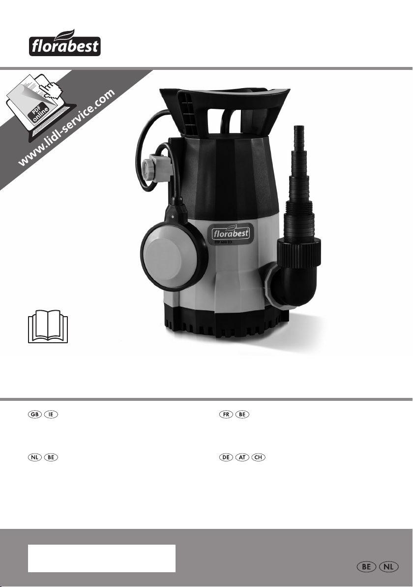
SUBMERSIBLE WATER PUMP FTP 400 D3
SUBMERSIBLE WATER PUMP
Translation of the original instructions
ZUIVER WATER-DOMPELPOMP
Vertaling van de originele gebruiksaanwijzing
POMPE À EAU CLAIRE IMMERGÉE
Traduction des instructions d‘origine
KLARWASSER-TAUCHPUMPE
Originalbetriebsanleitung
IAN 109771
Page 2

Before reading, unfold the page containing the illustrations and familiarise yourself with all functions of the
device.
Avant de lire le mode d‘emploi, ouvrez la page contenant les illustrations et familiarisez-vous ensuite avec
toutes les fonctions de l‘appareil.
Vouw vóór het lezen de pagina met de afbeeldingen open en maak u vertrouwd met alle functies van het
apparaat.
Klappen Sie vor dem Lesen die Seite mit den Abbildungen aus und machen Sie sich anschließend mit allen
Funktionen des Gerätes vertraut.
GB / IE Translation of the original instructions Page 4
FR / BE Traduction des instructions d‘origine Page 17
NL / BE Vertaling van de originele gebruiksaanwijzing Pagina 31
DE / AT / CH Originalbetriebsanleitung Seite 45
Page 3
7
10
1
10
11
7
12
9
8
56
4
½’’
¾’’
1’’
G 1 ½’’
2
3
13
8
13
9
10
12
5
8
7
1 ½’’
6
6
10
7
11a
11
11b
12
4a4b4
Page 4

GB IE
Content
Introduction .................................4
Special instructions for safe
operating .....................................5
Areas of Application ....................5
General Description ......................5
Scope of Delivery ..............................5
Overview ......................................... 6
Functional description ........................6
Technical Data ..............................6
Performance data ..............................6
Notes on Safety ...........................7
Symbols in the manual ....................... 7
Explanation of symbols ...................... 7
General notes on safety .....................7
Start-up .......................................9
Assembly .........................................9
Connection of the pressure line ...........9
To erect/suspend ..............................9
Controls before operational start-up ...10
Operation ..................................10
Mains connection ............................10
Switching on and off .......................10
Automatic mode..............................10
Manual mode/at suction ................ 11
Maintenance and Cleaning .........11
General cleaning instructions ............11
To replace the backow stop ............11
Clean pump pedestal ......................12
Storage ......................................12
Waste Disposal and
Environmental Protection ...........12
Replacement parts/Accessories ..13
Faults - Causes - Remedies .........14
Guarantee .................................15
Repair Service ............................16
Service-Center ............................16
Importer ....................................16
Translation of the original
EC declaration of conformity ......59
Exploded Drawing .....................61
Introduction
Congratulations on the purchase of your
new device. With it, you have chosen a
high quality product.
During production, this equipment has
been checked for quality and subjected
to a nal inspection. The functionality of
your equipment is therefore guaranteed. It
cannot be ruled out that residual quantities
of water or lubricants will remain on or in
the equipment/hose lines in isolated cases.
This is not a fault or defect and it represents no cause for concern.
The operating instructions constitute
part of this product. They contain
important information on safety, use
and disposal.
Before using the product, familiarise
yourself with all of the operating
and safety instructions. Use the
product only as described and for
the applications specied.
Keep this manual safely and in the
event that the product is passed on,
hand over all documents to the third
party.
4
Page 5

GB IE
Special instructions for
safe operating
• The equipment is not to be operated if there are people in the
water. There is a risk of electric
shock.
• Connect the equipment only
to a socket with a residual cur
rent protection device (residual
current circuit breaker) with a
rated current of not more than
30mA; minimum fuse 6 am
peres.
• If the power cable for this
equipment is damaged, it must
be replaced by the manufac
turer, a customer service agent
of the same or a similarly quali
ed person in order to prevent
hazards.
•
This appliance can be used
by children aged from 8 years
and above and persons with
reduced physical, sensory or
mental capabilities or lack of experience and knowledge if they
have been given supervision or
instruction concerning use of the
appliance in a safe way and understand the hazards involved.
Children shall not play with the
appliance. Cleaning and user
maintenance shall not be made
by children without supervision.
• Children should be supervised
to ensure that they do not play
with the appliance.
-
-
• Contamination of the liquid can
occur when the lubricant leaks
out.
• See further information in the
section on “Maintenance and
cleaning”.
Areas of Application
-
The submersible water pump acquired by
you is designed for pumping water with a
maximum temperature of 35°C.
This pump can be used e.g. to empty basins and tanks.
The pump is not suitable for commercial
use. Commercial use will invalidate the
guarantee.
The operator or user is responsible for accidents or damage to other people or their
-
property. The manufacturer shall not be
liable for damages caused by use other
than for which the equipment is intended
or by incorrect operation.
General Description
The illustration of the principal
functioning parts can be found
on the front foldout page.
Scope of Delivery
Carefully unpack the appliance and check
that it is complete. Dispose of the packaging material correctly.
- Submersible water pump (pump)
- Angle adapter + adapter with hose
connection
- 8m nylon rope
- Instructional manual
5
Page 6
GB IE
m
Overview
1 Carrying handle
2 Mains cable
3 Pump casing
4 Pump pedestal
5 Pump output
6 Float switch
7 Float switch height-adjustment
8 Float switch cable
9 Float switch guideway
10 Adapter with hose connection
11 backow stop (11a) with seal
(11b) (not visible)
12 Angle adapter
13 8 m nylon rope
4a 4 screws, pump pedestal
4b Cover plate, pump pedestal
Functional description
The pump is tted with a oat switch,
which automatically switches the equipment on or off.
In case of overload, the pump is switched
off by the integrated thermal protection
switch. After cooling, the motor restarts
automatically.
In addition, the pump also has a backow
stop that prevents water from owing back,
for example during an interruption in the
power supply.
Technical Data
Submersible water pump ........ FTP 400 D3
Mains connection ............ 230 V~, 50 Hz
Power consumption .....................400 W
Max. discharge rate (Qmax) ...10000 l/h
Max. discharge head (Hmax) ............ 7 m
Max. depth of immersion ..................7 m
Max. water temperature (Tmax) .......35°C
Hose connection .............½“, ¾“, 1“, 1 ½“
(13mm,19mm, 25mm, 38mm)
Tap connection with
interior thread ............. G1 ½“ (44,9mm)
Max. foreign body size ................ø 5 mm
Mains cable ..................................10 m
Weight (incl. accessories) .. approx. 4.0 kg
Safety class ..........................................I
Degree of protection ........................ IPX8
Technical and optical changes can be carried out in the course of further development
without notice. All dimensions, references
and information of this instruction manual are
therefore without guarantee. Legal claims,
which are made on the basis of the instruction
manual, cannot thus be considered as valid.
Performance data
The measurement of the maximum performance data takes place under optimal con-
ditions, such as a straight, direct exit. The
angle piece and backow stop may reduce
performance.
6
Page 7
GB IE
7 m
Notes on Safety
Symbols in the manual
Warning symbols (the danger
can be explained at the place
of the exclamation mark)
with information on damage
and injury prevention.
Instruction symbols (the instruction
can be explained at the place of
the exclamation mark) with information on preventing damage.
Help symbols with information on
improving tool handling.
Explanation of symbols
Caution! Not suitable for water
with a high sand content!
Read and follow the operating in-
structions provided for the device!
Attention: Remove the plug from the
socket as soon as the power lead is
damaged or cut.
Greatest possible operating immer-
sion depth.
Electric appliances should not be
disposed of in the domestic garbage.
General notes on safety
This section deals with the basic safety
regulations to be observed when working
with the machine.
Working with the equipment:
Caution: to avoid accidents and in-
juries:
• People who are unfamiliar with the
operating instructions are not permitted
to use the equipment. Local regulations
or bylaws may determine the minimum
age for using the device.
• Wear sturdy footwear to protect against
electric shock.
• Should there be people in the water,
do not operate the equipment. Risk of
electric shock!
• Take appropriate measures to keep children away from the equipment whilst it
is running. There is a risk of injury!
• Do not use the equipment in the vicinity
of ammable liquids or gases. Nonobservance will result in a risk of re or
explosion.
• The transportation of aggressive, abrasive (grinding effect), corrosive, combustible (e.g. motor fuels) or explosive
liquids, salt water, cleaning agents and
foodstuffs is not permitted. The temperature of the liquid being transported must
not exceed 35°C.
• Store the equipment in a dry place and
out of reach of children.
Caution! To avoid damage to the
equipment and any possible person
injury resulting from this:
• Do not work with damaged or incomplete equipment, or with equipment that
has been converted without the approval of the manufacturer. Before initial operation, have a specialist check that the
required electrical protection measures
are in place.
• Monitor the equipment during opera-
7
Page 8

GB IE
tion (particularly in residential spaces,
in order to detect automatic switching
off or dry running of the pumps in time.
Regularly check the function of the oat
switch (see chapter “initial operation“).
Non-observance will invalidate all guarantee and liability claims.
• Please note that the pump is not suitable
for continuous operation (e.g. for watercourses in garden ponds). Check the
equipment regularly for correct functioning.
• Note that the lubricants used in the
equipment may cause damage or contamination if they escape. Do not use
the pump in garden ponds with sh
stocks or valuable plants.
• Do not carry or x the equipment by the
cable or pressure line.
• Protect the equipment from frost and
from running dry.
• Use only original accessories and do not
carry out conversion work on the equipment.
• Please read the notes in the operating
instructions on the topic of “maintenance
and cleaning”. Any measures above
and beyond these, particularly opening
the equipment, are to be carried out by
an electrician. In the case of repairs,
always contact our service centre.
Electrical safety:
Caution: to avoid accidents and inju-
ries from electric shocks:
• The equipment is not to be operated if
there are people in the water. There is a
risk of electric shock.
• After erection, the mains plug must be
freely accessible when the equipment is
in operation.
• Before operating your new pump, have
a specialist check:
- The earthing, the protective multiple
earthing; the residual current circuit
breaking must be compliant with
the safety regulations of the energy
supply company and function without fault,
- The protection of the electrical plug
connections from the wet.
• If there is a risk of ooding, x the
plug connections in an area that is safe
from ooding.
• Ensure that the mains voltage matches
the specications on the rating plate.
• The electrical installation shall be ac-
cording to national wiring rules.
• Before each use, check the equipment,
cable and plug for damage. Defective cables are not to be repaired, but
rather replaced by new ones. Have
damage on your equipment repaired
by an authorised specialist.
• Do not pull the plug from the socket by
the cable. Protect the cable from heat,
oil and sharp edges.
• Do not carry or x the equipment by
the cable.
• Use only extension cables that are protected from spray water and designed
for outdoor use. Always fully unroll a
cable drum before use. Check the cable for damage.
• Disconnect the mains plug from the
socket before all work on the equipment, in case of leaks in the water
system, during work breaks, and when
not in use.
• The cross-section of mains connection
lines must be no smaller than rubber hose lines with the designation
H05RN8-F. The line must be 10 m
long. The exible lead cross-section
of the extension cord must at least
2.5mm
2
.
8
Page 9
GB IE
Start-up
Assembly
To screw-on the adapter:
1. Screw the angle adapter (12)
and the adapter with the hose
connection (10) onto the pump
outlet (5).
Tomounttheoatswitch
height adjustment
2. Loosen the screw of the oat
switch height adjustment (7) and
push the adjustment over the
oat switch guideway (9). Check
that the oat switch cable (8)
moves upward (arrow
up) (see „Operation“).
Connection of the pressure
line
The installation of the submersible water
pump is implemented either
- with xed pipe or
- with exible hose line
to point
The measurement of the maximum
performance data takes place
under optimal conditions, such as
a straight, direct exit. The angle
adapter (
stopper (
To increase pump output, the backow
stopper (11) may be taken out of the angle
adapter (12) (see
stopper”). This is particularly recommended for hose connections smaller than
1“. Please bear in mind that the water may
then ow back during pumping, or in the
event of a power cut.
12) and the backow
11) may reduce output.
“replacing backow
To erect/suspend
The pump can be erected or sus-
pended in the water.
The cord (
delivery contents may be used to
suspend and/or extract the pump.
The pump shaft should have the dimensions 40 x 40 x 50cm at least, so that the
oat switch can move freely.
13) contained in the
• If using a ½” hose, attach the
hose over the pump’s hose connection (10) and fasten it with a
hose clamp if necessary.
• To use a ¾”, 1“ or 1½” hose,
cut off the connection above and
attach the hose over the correct
connection (xing with a hose
clamp).
• To use a tap adaptor (IG1½“)
to connect external hose connection systems, cut off the three top
connections directly above the
G1½“ tube thread.
Fix the nylon rope (13) onto the car-
rying handle (1).
Ensure that the equipment is
not hung up or held by the
mains cable. There is a risk
of electric shock from damaged mains cables.
Note that, over time, dirt and sand
may collect on the bottom of the
shaft, which could damage the
pump.
We recommend placing the pump
on a brick or a grid.
9
Page 10
GB IE
If the water level is too low, the silt
in the shaft can quickly dry out and
impede the pump when warming
up.
Controls before operational
start-up
• Check that the oat switch is
working (see chapter: “Operation“).
• Check that the pump is resting
on the pit base
• Check that the pressure line has
been attached properly
• Check the proper status of the
electrical plug socket and make
sure that the plug socket is sufciently fused (at least 6 A). Insert the pump plug into the plug
socket and the pump is ready for
operation.
• Make sure that moisture or water
never come in contact with the
mains connection.There is a risk
of electrocution.
Operation
Mains connection
Switching on and off
1. Insert the plug in the socket. The pump
starts working immediately.
The pump immediately starts running
when the swimming switch is in the
correct position (see „Automatic operation“ and „Manual operation“).
2. To switch off, withdraw the plug from
the socket. The pump stops.
If the water level is too low, the
oat switch will automatically
switch off the pump.
Supervise the appliance while it is
in operation in order to be immediately aware if the automatic cut-out
operates or the pump runs dry, to
limit any damage to a minimum.
Automatic mode
In automatic mode, the oat switch ( 6)
automatically switches the pump on or off.
In the case of stationary installation,
check regularly (no less then once
every three months) that the oat
switch (
6) is working.
The submersible water pump acquired by
you is already provided with an grounded
plug. The equipment is designed for con-
nection to an earthed wall socket with a
residual current operated device (RCD
switch) at 230 V ~ 50Hz.
Only start to operate the device
after all the above conditions have
been observed.
10
The On/Off switch point of the oat switch
(
6) is innitely variable:
Loosen the screw in the oat switch
height adjustment (5) and move it
to the desired position.
Check the oat switch ( 6).
- It must be positioned so that it
can lift and lower freely. The
switching point heights “On” and
“Off” must be easy to reach.
Page 11

GB IE
Check this by placing the pump
into a vessel lled with water
and lift the oat switch (
carefully by hand and then lower it again. In this case, you can
see whether the pump switches
on and off.
- Also ensure that the separation
distance between the oat switch
(6) head and the oat switch
height adjustment (5) is not too
small. In the case of a separation distance which is too small,
trouble-free functioning cannot
be guaranteed.
- During the adjustment of the oat
switch (
oat switch does not contact the
oor before the pump switches
off.
The pump run dry if too long a
oat switch cable (
particularly if the oat switch height
adjustment (
(see „Operational start-up“).
6), ensure that the
5) is not installed
6)
3) is chosen,
Manual mode/at suction
In manual mode, the pump does not switch
off automatically, as the oat switch (
is bypassed.
Position the oat switch (6) vertical-
ly upward in the oat switch height
adjustment (5).
6)
Maintenance and
Cleaning
Clean and maintain your equipment regu-
larly. This will guarantee its performance
and long durability.
Ask our service centre to car-
ry out any work that is not
described in these instructions. Use only original parts.
There is a risk of injury!
Pull out the power plug before
every maintenance operation. There
is a risk of electrocution or of injury
from moving parts.
General cleaning instructions
• In case of transport for utilization in
different locations, the pump must be
cleaned with clear water after every
use.
• In case of stationary installation, the
function of the oat switch (
to be checked regularly (at the latest
every three months).
• With a water jet, remove uff and
brous particles which are possibly
present in the pump casing (
• Clean precipitation from the oat
switch (
• Regularly remove sludge from the pit
base (at the latest every 3 months) and
also clean the shaft walls
6) with clear water.
6) is
3).
Monitor the pump constantly when
in manual mode. Switch the pump
off immediately (disconnect from
the mains) if no more water is being pumped. There is a risk of damage if the pump runs dry.
To replace the backow stop
Replace a defective backow stop (see
“Replacement parts/Accessories”).
11
Page 12

GB IE
1. Unscrew the adapter with the
hose connection (10) on the
angle adapter (12) and remove
the backow stop (11a) and seal
(11b).
2. Insert the seal (11b) into the
back ow stop (11a).
3. Set the backow stop (11) be-
tween the angle adapter (12)
and the adapter with the hose
connection (10) in such a manner that the stop is opened in
the owing direction and closed
against the owing direction.
Clean pump pedestal
Always remove the mains plug be-
fore working on the device.
Moving parts create the risk of elec-
trocution or injury.
Dirt on the underside of the pump can be
removed after removing the cover plate
(4b) on the pump pedestal (4):
1. Loosen the 4 screws (4a) on the
underside of the pump pedestal
(4) and remove the cover (4b).
2. Remove the dirt from the underside of the pump with running
water. Do not use your ngers.
3. Screw the cover plate (4b) back
on.
Storage
• Clean the pump before storage.
• Store the appliance in a dry, frost-free
place, and where children cannot gain
access to it.
• When the pump is not to be used for
a longer period, it must be thoroughly
cleaned after its last use, and before it
is next used. Otherwise there may be
problems in starting the pump, caused
by deposits and residues.
Waste Disposal
and Environmental
Protection
Be environmentally friendly. Return the
tool, accessories and packaging to a recy-
cling centre when you have nished with
them.
Electric appliances should not be
disposed of in the domestic garbage.
Hand the tool in at a recycling centre. The
plastics and metal parts can be separated
and recycled. Ask your Service Center
about this. Defective units returned to us
will be disposed of for free.
Any measures above and beyond these, particularly opening the equipment, are to be
carried out by an electrician. In the case of
repairs, always contact our service centre.
12
Page 13

GB IE
Replacement parts/Accessories
Spare parts and accessories can be obtained at
www.grizzly-service.eu
If you do not have internet access, please contact the Service Centre via telephone
(see “Service-Center” page 16). Please have the order number mentioned below ready.
Item Item Description Order
Instruction Exploded number
manual drawing
4a 40 Screw set for pump pedestal 91101225
4b 39 Cover plate, pump pedestal 91101224
10/11 35/41 Adapter with hose connection,
with backow stop 91101246
12 34 Angle adapter 91101245
The backow stop is subject to wear; its replacement is not covered by guarantee.
13
Page 14
GB IE
Faults - Causes - Remedies
Faults Causes Remedies
Pump does not start
Pumps has no discharge
Pump does not switch
off
Flow rate insufcient
- Mains voltage is not applied
- Float switch (
switch
- Pump pedestal (
grating blocked
- Reduces pump performance,
through severely contaminated water and additions in
the water which produce a
grinding effect
- Backow stop (
incorrectly tted or faulty
- Float switch cannot drop - Set up pumps correctly on the
- Pump pedestal (
grating blocked
- Reduces pump performance,
through severely contaminated water and additions in
the water which produce a
grinding effect
- Backow stop (
incorrectly tted or faulty
- Backow stop (
duces pump performance
6) does not
4) inlet
11) is
4) inlet
11) is
11) re-
- Check mains voltage
- Bring oat switch into higher
position
- Use a water jet to clean the
pump pedestal inlet grating
- Clean pump
- Check the backow stop’s
connection. Change it if
necessary (see “Maintenance
and Cleaning”)
pit base
- Use a water jet to clean the
pump pedestal inlet grating
- Clean pump
- Check the backow stop’s
connection. Change it if
necessary (see “Maintenance
and Cleaning”)
- Remove the backow stop
from the angle adapter (
12) (see “Start-up”)
Pump switches off
after a short period
14
- Motor contactor disconnects
the pumps because of water
pollution that is too severe.
- Water temperature too high,
motor contactor breaks
- Pull out power plug and
clean the pump as well as
shaft
- Note maximum water temperature of 35°C!
Page 15

GB IE
Guarantee
Dear Customer,
This equipment is provided with a 3-year
guarantee from the date of purchase.
In case of defects, you have statutory rights
against the seller of the product. These
statutory rights are not restricted by our
guarantee presented below.
Terms of Guarantee
The term of the guarantee begins on the
date of purchase. Please retain the original
receipt. This document is required as proof
of purchase.
If a material or manufacturing defect occurs
within three years of the date of purchase
of this product, we will repair or replace –
at our choice – the product for you free of
charge. This guarantee requires the defective equipment and proof of purchase to be
presented within the three-year period with
a brief written description of what constitutes
the defect and when it occurred.
If the defect is covered by our guarantee, you
will receive either the repaired product or a
new product. No new guarantee period begins on repair or replacement of the product.
Guarantee Period and Statutory
Claims for Defects
The guarantee period is not extended by
the guarantee service. This also applies for
replaced or repaired parts. Any damages
and defects already present at the time of
purchase must be reported immediately after unpacking. Repairs arising after expiry
of the guarantee period are chargeable.
Guarantee Cover
The equipment has been carefully produced
in accordance with strict quality guidelines
and conscientiously checked prior to delivery.
The guarantee applies for all material and
manufacturing defects. This guarantee
does not extend to cover product parts that
are subject to normal wear and may therefore be considered as wearing parts (e.g.
backow stop, sealing ring) or to cover
damage to breakable parts (e.g. switches,
batteries, or parts made of glass).
This guarantee shall be invalid if the product has been damaged, used incorrectly or
not maintained. Precise adherence to all of
the instructions specied in the operating
manual is required for proper use of the
product. Intended uses and actions against
which the operating manual advises or
warns must be categorically avoided.
The product is designed only for private
and not commercial use. The guarantee
will be invalidated in case of misuse or
improper handling, use of force, or interventions not undertaken by our authorised
service branch.
In the case of pumping water containing sand or aggressive liquids or other
incorrect, non-design-appropriate use, as
well as in case of non-observance of the
operating manual, application of force in
use or inappropriate or insufcient maintenance, no guarantee claim exists, since
seals, impeller wheel, motor or other parts
are damaged by this. Also, sewage water
pumps are not suitable for the pumping of
abrasive materials (sand, stone).
Note: submersible pumps are drainage
pumps. This kind of pump is constructed
with the purpose of transporting or removing a certain volume of water – depending
on its output category – as quickly as possible. Submersible pumps are not intended
as irrigation (for example, in garden ir-
rigation systems) or as constant water-ow
pumps (such as in articial streams or or-
namental fountains). Inappropriate use will
15
Page 16

GB IE
invalidate the warranty.
Periodically check that the oat switch is
operational. Warranty and liability claims
will be void in case on non-compliance or
if the pump runs dry.
In particular, the guarantee is likewise void
in the case of employment of the sewage
water pumps without base plate or (this
applies for all pumps) in case of damages
which are caused by supporting on or sus-
pending from the mains cable. The pumps
must not be run dry or exposed to frost.
Processing in Case of Guarantee
To ensure quick handling of you issue,
please follow the following directions:
• Please have the receipt and identication number (IAN 109771) ready as
proof of purchase for all enquiries.
• Please nd the item number on the rating plate.
• Should functional errors or other defects occur, please initially contact the
service department specied below by
telephone or by e-mail. You will then
receive further information on the processing of your complaint.
• After consultation with our customer
service, a product recorded as defective can be sent postage paid to the
service address communicated to you,
with the proof of purchase (receipt)
and specication of what constitutes
the defect and when it occurred. In order to avoid acceptance problems and
additional costs, please be sure to use
only the address communicated to you.
Ensure that the consignment is not sent
carriage forward or by bulky goods,
express or other special freight. Please
send the equipment inc. all accessories
supplied at the time of purchase and
ensure adequate, safe transport packaging.
Repair Service
For a charge, repairs not covered by the
guarantee can be carried out by our ser-
vice branch, which will be happy to issue
a cost estimate for you.
We can handle only equipment that has
been sent with adequate packaging and
postage.
Attention: Please send your equipment to
our service branch in clean condition and
with an indication of the defect.
Equipment sent carriage forward or by
bulky goods, express or other special
freight will not be accepted.
We will dispose of your defective devices
free of charge when you send them to us.
Service-Center
Service Great Britain
GB
Tel.: 0871 5000 720
(£ 0.10/Min.)
E-Mail: grizzly@lidl.co.uk
IAN 109771
Service Ireland
IE
Tel.: 1890 930 034
(0,08 EUR/Min., (peak))
(0,06 EUR/Min., (off peak))
E-Mail: grizzly@lidl.ie
IAN 109771
Importer
Please note that the following address is
not a service address. Please initially con-
tact the service centre specied above.
Grizzly Tools GmbH & Co. KG
Stockstädter Straße 20
63762 Großostheim, Germany
www.grizzly-service.eu
16
Page 17

FR BE
Sommaire
Introduction ...............................17
Consignes particulières pour une
utilisation en toute sécurité .........17
Fins d’utilisation ......................... 18
Description générale ..................18
Volume de la livraison ..................... 18
Vue synoptique ............................... 19
Description du fonctionnement .......... 19
Détails techniques ...................... 19
Performances .................................. 20
Instructions de sécurité ............... 20
Symboles utilisés dans le mode
d’emploi ........................................20
Explication des symboles et des avis de
sécurité .......................................... 20
Consignes générales de sécurité ....... 20
Mise en service ..........................22
Instructions de montage ................... 22
Raccordement de la conduite forcée .. 22
Mettre en place/accrocher ............... 23
Contrôls devant la mise en marche .... 23
Service .......................................24
Le raccordement au réseau ............... 24
Mise en marche et arrêt ................... 24
Mode automatique .......................... 24
Mode manuel/Aspiration à plat ........ 25
Entretien et nettoyage ................ 25
Travaux d’entretien et de nettoyage
généraux ....................................... 25
Remplacement du clapet de non-retour ..25
Nettoyage du pied de la pompe ....... 26
Stockage ....................................26
Protection de l’environnement .... 26
Pièces de rechange/Accessoires .. 27
Dépannage ................................ 28
Garantie ....................................29
Service Réparations ...................30
Service-Center ............................ 30
Importeur .................................. 30
Traduction de la déclaration de
conformité CE originale ..............60
Vue éclatée ................................61
Introduction
Toutes nos félicitations pour l’achat de
votre nouvel appareil. Vous avez ainsi
choisi un produit de qualité supérieure.
La qualité de l’appareil a été vériée
pendant la production et il a été soumis
à un contrôle nal. Le fonctionnement de
votre appareil est donc ainsi garanti. Il
n’est pas à exclure que dans certains cas
isolés, il demeure dans l’appareil, ou dans
les tuyauteries exibles, des quantités résiduelles d’eau ou de lubriants industriels.
Ceci n’est pas un défaut ou un vice et on
ne doit pas s’inquiéter à ce sujet.
La notice d’utilisation fait partie de
ce produit. Elle contient des instruc-
tions importantes pour la sécurité,
l’utilisation et l’élimination des
déchets. Avant d’utiliser ce produit,
lisez attentivement les consignes
d’emploi et de sécurité. N’utilisez le
produit que tel que décrit et unique-
ment pour les domaines d’emploi
indiqués.
Conservez cette notice et remet-
tez-la avec tous les documents si
vous cédez le produit à un tiers.
Consignes particulières
pour une utilisation en
toute sécurité
• L’appareil ne doit pas être utili-
sé si des personnes se trouvent
dans l’eau (p. ex. en cas des
travaux de nettoyage ou de
maintenance aux piscines). Il
existe un danger par choc élec
trique.
-
17
Page 18

FR BE
•
Branchez l‘appareil seulement
sur une prise de courant avec
un dispositif de protection de
courant de défaut (commutateur
FI) avec un courant de référence
d‘un maximum de 30 mA ; pro
-
tection au moins 6 ampères.
• Si le câble d’alimentation est
endommagé, il doit être rempla
cé par le fabricant, son service
après vente ou des personnes
de qualication similaire an
d’éviter un danger.
• Cet appareil peut être utilisé par
des enfants à partir de 8ans
et plus et par des personnes
ayant des capacités physiques,
sensorielles ou mentales réduites
ou un manque d’expérience et
de connaissances à condition
qu’elles aient reçu une supervi
sion ou des instructions concernant I’utilisation de I’appareil
en toute sécurité et qu’elles com
prennent les dangers encourus.
Les enfants ne doivent pas jouer
avec l’appareil. Le nettoyage
et I’entretien par I’usager ne
doivent pas être effectués par
des enfants sans surveillance.
• Il convient de surveiller les en-
fants pour s’assurer qu’ils ne
jouent pas avec l’appareil.
• La pollution du liquide peut pro-
venir d’une fuite de lubriants.
• Respectez les autres consignes
abordées dans le chapitre «
Maintenance et nettoyage ».
Fins d’utilisation
La pompe à eau immergée est conçue pour
pomper de l‘eau jusqu‘à une température
maximale de 35°C.
Elle est adaptée, par exemple, pour pomper et transvaser depuis un bassin vers des
conteneurs et de l‘eau d‘une cave inondée.
Cet appareil n’est pas adapté à une utilisa-
-
tion industrielle. Toute utilisation industrielle
met n à la garantie.
L‘opérateur ou l‘utilisateur est responsable
des accidents ou des dégâts sur les per-
sonnes et sur les biens.
Le fabricant n‘est pas responsable des
dégâts qui ont été causés par un usage
contraire aux prescriptions ou par une
utilisation non conforme.
Description générale
Vous trouverez les illustrations
sur la page de rabat avant.
Volume de la livraison
-
Déballez l’appareil et vériez que la livraison est complète. Evacuez le matériel
d’emballage comme il se doit.
- Pompe
- Adaptateur d‘angle et adaptateur avec
raccord de tuyau
- 8 m de câble de nylon
- Mode d’emploi
18
Page 19

FR BE
Vue synoptique
1 Poignée
2 Conduite de réseau
3 Boîtier de la pompe
4 Pied de la pompe
5 Sortie de pompe
6 Interrupteur à otteur complet
7 Réglage en hauteur de l’interrup-
teur à otteur
8 Câble d’interrupteur à otteur
9 Asservissement d’interrupteur à
otteur
10 Adaptateur avec raccord de
tuyau
11 Clapet de non-retour (11a) avec
joint (11b) (non visible)
12 Adaptateur d‘angle
13 8 m de câble de nylon
4a 4 vis, pied de la pompe
4b Plaque de protection, pied de la
pompe
Description du
fonctionnement
La pompe est équipée d’une commande à
otteur qui la met automatiquement en ou
hors circuit, en fonction du niveau d’eau.
En cas de surcharge, la pompe est arrêtée
par le disjoncteur thermique incorporé.
Après refroidissement, le moteur redémarre
tout seul.
La pompe est de plus équipée d’un clapet
anti-retour qui empêche l’eau de reuer,
par exemple lors d’une panne de courant.
Détails techniques
Type ............................ FTP 400 D3
Raccordement au réseau ...230 V~, 50 Hz
Puissance ................................... 400 W
Max. ux de pompage (Qmax) ..10000 l/h
Max. hauteur de pompage (Hmax) .... 7 m
Profondeur d’immersion max. ............ 7 m
Max. température de l’eau (Tmax) ... 35° C
Raccord de tuyau .......... ½“, ¾“, 1“, 1 ½“
(13mm,19mm, 25mm, 38mm)
Raccord de robinet avec
let intérieur ...............G1 ½“ (44,9mm)
Corps étrangers max. ................. Ø 5 mm
Conduite de réseau ........................ 10 m
Poids (y compris accessoires) ... env. 4,0 kg
Classe de protection .............................. I
Mode de protection ..........................IPX8
Des modications techniques et optiques
en vue d’un perfectionnement sont pos-
sibles sans notication préalable. C’est
pourquoi toutes les dimensions, informa-
tions, remarques et déclarations mentionnées dans ce manuel sont sans engagement de notre part. Par conséquent, des
prétentions à des revendications juridiques
qui se basent sur le manuel d’instructions
d’emploi seront sans effet.
19
Page 20

FR BE
m
7 m
Performances
La mesure des données de performance
maximales dans des conditions optimales
se fait comme une sortie directe droite.
L’adaptateur d’angle peut réduire la puissance de l‘appareil.
Instructions de sécurité
Symboles utilisés dans le
mode d’emploi
Symbole de danger et indica-
tions relatives à la prévention
de dommages corporels ou
matériels.
Symbole d’interdiction (l’interdiction
est précisée à la place des guillemets) et indications relatives à la
prévention de dommages.
Symboles de remarque et informa-
tions permettant une meilleure utilisation de l‘appareil.
Explication des symboles et
des avis de sécurité
Attention!
Non approprié pour l’eau très
sableuse !
Lisez et respectez le mode d’emploi
de l’appareil.
Attention! Si le câble de réseau est
détérioré ou coupé, tirez immédiatement la che de la prise de cou-
rant.
Profondeur d’immersion maximale
Les machines n’ont pas leur place
dans les ordures ménagères.
Consignes générales de
sécurité
Cette section traite des principales normes
de sécurité lors de travaux avec l‘appareil.
Travaux avec l‘appareil :
Prudence : vous éviterez ainsi acci-
dents et blessures :
• Les personnes qui ne connaissent pas le
mode d‘emploi ne doivent pas utiliser
l‘appareil. Il se peut que des disposi-
tions locales xent l’âge minimum de
l‘utilisateur.
• Portez des chaussures de sécurité an
d’être isolé des éventuelles décharges
électriques.
• Prenez toutes les mesures appropriées
pour tenir les enfants éloignés de l‘ap-
pareil lorsque celui-ci fonctionne. Vous
risquez de vous blesser.
20
Page 21

FR BE
• N‘utilisez pas l‘appareil à proximité de
liquides inammables ou de gaz. En
cas d‘inobservation de cette consigne, il
y a risque d‘incendie ou d‘explosion.
• L‘utilisation de liquides agressifs, abra-
sifs (ayant un effet déclencheur), décapants, inammables (par exemple des
carburants pour moteur) ou explosifs,
d‘eau salée, de produits de nettoyage
et alimentaires est interdite. La température du liquide pompé ne peut pas
dépasser 35 °C.
• Conservez l‘appareil dans un endroit
sec et hors de portée des enfants.
Prudence! Vous évitez ainsi d‘en-
dommager l‘appareil et les éventuelles conséquences pouvant affec-
ter les personnes :
• Ne travaillez pas avec un appareil
endommagé, incomplet ou sans consentement du fabricant de l‘appareil si
celui-ci a été modié. Avant la mise en
service, faites contrôler par un spécialiste que les mesures de protection électriques exigées sont disponibles.
• Contrôlez l‘appareil pendant son exploitation (notamment dans les locaux d‘habitation) pour détecter à temps la déconnexion automatique ou un fonctionnement à vide de la pompe. Contrôlez
régulièrement le fonctionnement de
l‘interrupteur ottant (cf. chapitre « Mise
en service »). L‘inobservation de cette
consigne met n aux droits de garantie
et à la responsabilité.
• Veuillez ne pas oublier que la pompe
n‘est pas adaptée à une exploitation
en continu (par exemple pour des cours
d‘eau, dans des étangs). Contrôlez
régulièrement le bon fonctionnement de
l‘appareil.
• N‘oubliez pas que l‘appareil utilise
des lubriants, lesquels en cas de fuite,
peuvent s‘écouler et causer des dom-
mages ou des pollutions. Ne placez pas
la pompe dans des étangs contenant
des poissons ou des plantes de valeur.
• Ne portez pas ou ne xez pas l‘appareil par le câble ou le tuyau de refoule-
ment.
• Protégez l‘appareil du gel et du fonctionnement à sec.
• Utilisez seulement des accessoires d‘ori-
gine et ne modiez pas l‘appareil.
• En ce qui concerne le thème « Mainte-
nance et nettoyage », veuillez lire les
instructions du mode d‘emploi. Toutes
les tâches concernant ce sujet, en parti-
culier l‘ouverture de l‘appareil, doivent
être exécutées un électricien de métier.
En cas de réparation, adressez vous
toujours à notre service après-vente.
Sécurité électrique :
Prudence : vous éviterez ainsi les
blessures et les accidents dus au
choc électrique :
• Lorsque l‘appareil fonctionne après
avoir été mis en place, la che de secteur doit être accessible.
• Avant que vous ne mettiez en service
votre nouvelle pompe, faites contrôler
par un professionnel :
- que la mise à la terre, la liaison au
neutre, le circuit de protection de
courant de défaut correspondent
aux normes de sécurité des entreprises d‘approvisionnement en éner-
gie et fonctionnent correctement,
- que les raccordements électriques
sont protégés de l‘humidité.
21
Page 22

FR BE
• En cas de risque d‘inondation les rac-
cordements doivent être situés dans une
zone à l‘abri des inondations. Danger
de décharge électrique.
• Faites attention à ce que la tension de
réseau corresponde aux indications de
la plaque signalétique.
• Avant toute utilisation, contrôlez l‘appa-
reil, le câble et la prise pour détecter
tout dommage. Les câbles défectueux
ne peuvent pas être réparés mais
doivent être échangés contre de nouveaux. Faites réparer les dommages
survenus à votre appareil par un spécialiste autorisé.
• N‘utilisez pas le câble pour tirer sur la
prise de courant. Protégez le câble de
la chaleur, de l‘huile et des bords coupants.
• Ne portez pas ou ne xez pas l‘appareil par le câble.
• Utilisez seulement des câbles de prolongation qui sont étanches aux jets d‘eau
et prévus pour être utilisés en plein air.
Avant utilisation, déroulez toujours la
totalité du câble. Contrôlez le câble an
de détecter tout dommage.
• Avant tout travail sur l’appareil, en
cas de non-étanchéité dans le système
d’eau, pendant les pauses et en cas de
non utilisation, retirez la che secteur
de la prise de courant.
• Les conduites d‘alimentation ne doivent
pas avoir de plus petite coupe transver-
sale que des câbles sous caoutchouc
avec la marque H05RN8-F. La longueur
de ligne doit être de 10 m. La section
du toron de la rallonge doit être égale
ou supérieure à 2,5 mm
2
.
Mise en service
Instructions de montage
Visser l’adaptateur
1. Vissez l‘adaptateur d‘angle (12)
et l‘adaptateur avec raccord de
tuyau (10) sur la sortie de pompe
(5).
Monter le réglage en hau-
teur pour l’interrupteur à
otteur
2. Desserrez la vis de réglage en
hauteur de l’interrupteur à otteur
(7) et poussez celui-ci dans la di-
rection de l’interrupteur à otteur
(9). De plus, le câble d’interrupteur à otteur (8) doit être dirigé
vers le haut (la èche
orientée vers le haut) (voir «Ser-
vice»).
Raccordement de la conduite
forcée
L’installation de la pompe à eau immergée
est effectuée:
- soit sur une tuyauterie xe
- soit sur des tuyaux exibles
• Si vous utilisez un tuyau en ½“,
emboîtez-le sur l’adaptateur
avec raccord de tuyau (10) de
la pompe et xez-le à l’aide d’un
collier de serrage.
• Si vous utilisez un tuyau en ¾“,
1“ ou 1½“, coupez l’embout pla-
cé au-dessus et emboîtez ensuite
le tuyau sur l’embout correspondant (xation avec collier de ser-
rage).
doit être
22
Page 23

FR BE
• Si vous utilisez une pièce de
robinet (IG1½“) pour le raccordement de systèmes d’embouts de
tuyaux externes, coupez les trois
embouts supérieurs juste au-dessus du letage du tube G1½ “.
La mesure des données de perfor-
mance maximales dans des conditions optimales se fait comme une
sortie directe droite. L’adaptateur
d’angle (
tour (
puissance.
Il est possible de retirer le clapet de non-retour (11) de l’adaptateur (12) pour augmenter la puissance de la pompe (voir
«remplacement du clapet de non-retour»).
Ceci est notamment recommandé pour les
embouts de tuyaux inférieurs à 1“. Tenez
compte du fait que le reux de l’eau peut
toutefois éventuellement survenir en cas
de coupure de courant ou de panne des
pompes.
12) et clapet de non-re-
11) peuvent réduire la
Mettre en place/accrocher
La pompe peut être placée ou ac-
crochée dans l’eau. Pour accrocher
et / ou tirer la pompe, vous pouvez
utiliser le câble (
dans le volume de la livraison.
Il serait préférable que la fosse de la
pompe ait les dimensions suivantes:
40 x 40 x 50 cm an que l’interrupteur à
otteur puisse se déplacer librement.
13) contenu
Faites attention à ce qu‘en
aucun cas l‘appareil ne soit
xéoususpenduparlecâble
d‘alimentation secteur. Il y a
alors danger d‘une décharge
électriqueparlescâbles
d‘alimentation secteur endommagés.
Faites attention qu‘avec le temps,
il n‘y ait pas de saleté ou de sable
qui s‘accumule dans le puits, ce qui
pourrait endommager la pompe.
Nous recommandons de placer la
pompe sur une brique ou sur une
grille.
Si la surface du plan d‘eau est trop
petite, la vase présente dans le
puits peut se dessécher rapidement
et empêcher la pompe de fonctionner.
Contrôls devant la mise en
marche
• Contrôlez le fonctionnement de
l’interrupteur à otteur (voir «Service»).
• Vériez que la pompe est bien
posée sur le sol de la fosse.
• Vériez que la conduite forcée est
montée correctement.
• Vériez que la prise électrique est
en bon état (au moins de 6A).
• Evitez que la pompe fonctionne à
sec. Il y a le risque d’une électrocution.
Fixez le câble de nylon (13) à la
poignée de transport (1).
23
Page 24

FR BE
Service
Le raccordement au réseau
La pompe que vous avez acquise est déjà
munie d’un interrupteur de sécurité. L’appa-
reil a été conçu pour un raccordement à un
socle de prise de courant de sécurité avec
un dispositif de protection par courant
de défaut (commutateur FI) avec 230 V ~
50Hz.
Ne mettez l’appareil en marche
que sous respect de tous les points
précités.
Mise en marche et arrêt
1. Branchez le câble d’alimentation dans
la prise de courant. La pompe démarre
immédiatement.
La pompe démarre immédiatement
lorsque l‘interrupteur ottant se trouve
dans la position correcte (voir « Mode
automatique » et « Mode manuel »).
2. Pour débrancher, retirer le connecteur
de la prise de courant. La pompe s’arrête.
Si le niveau de l‘eau est trop faible,
le commutateur ottant arrête automatiquement la pompe.
Surveillez l’appareil pendant son
fonctionnement an de constater,
en temps utile, une marche à sec de
la pompe et éviter ainsi des dommages.
Mode automatique
En mode automatique, l’interrupteur à
otteur (
s’arrête automatiquement.
6) de la pompe s’enclenche et
En cas d’installation stationnaire,
l’interrupteur à otteur (
être contrôlé régulièrement (au plus
tard tous les trois mois).
Le point de commutation Marche/Arrêt
de l‘interrupteur à otteur (
réglé de manière continue :
Desserrez la vis de réglage en hau-
teur de l‘interrupteur à otteur (7) et
positionnez celui-ci dans la position
souhaitée.
Contrôlez l’interrupteur à otteur
(
6).
- Il doit être positionné de telle
sorte qu’il puisse se lever et
s’abaisser librement. La hauteur du point de commutation
«Marche» et la hauteur du point
de commutation «Arrêt» doivent
pouvoir être atteints facilement.
Vériez en plaçant la pompe
dans un récipient rempli d’eau
et soulever avec précaution l’interrupteur à otteur à la main et
ensuite le laisser retomber. Ce
faisant, vous pouvez remarquer
si la pompe se met en marche ou
s’arrête.
- Veillez à ce que l’espace entre
l’interrupteur à otteur (6) et le
réglage en hauteur de l’interrupteur à otteur (7) ne soit pas trop
réduit. Si l’espace est trop réduit, le
fonctionnement sans faille n’est pas
garanti.
- Lors du réglage de l’interrupteur
à otteur (6), veillez à ce que
celui-ci ne touche pas le sol avant
l’arrêt de la pompe.
6) doit
6) peut être
24
Page 25

FR BE
Il existe un danger de fonctionne-
ment à sec, si le câble d’interrupteur à otteur (
en particulier si le réglage en hauteur de l’interrupteur à otteur (
7) n’est pas monté (voir la « mise
en service »).
8) est trop long,
Mode manuel/Aspiration à
plat
En mode manuel, la pompe ne s’arrête pas
automatiquement car l’interrupteur à otteur (
6) est dérivé.
Positionnez l’interrupteur à otteur
(6) verticalement vers le haut dans
le réglage en hauteur de l’interrupteur à otteur (7).
En mode manuel, observez la
pompe en permanence. Arrêtez
immédiatement la pompe (retirer la
che de secteur) si aucune eau n’est
plus pompée. Si la pompe travaille
à sec, vous risquez de l’endommager.
Entretien et nettoyage
La pompe est un produit de qualité ayant
fait ses preuves et qui a été soumis a un
contrôle nal sévère. Toutefois, pour augmenter la longévité, nous recommandons
un contrôle et un entretien réguliers.
Si vous faites exécuter des
travaux qui ne sont pas
décrits dans cette directive,
adressez vous à notre service
après-vente. Utilisez seulement des pièces d‘origine.
Vous risquez de vous blesser.
Débrancher la pompe avant
chaque travail d’entretien. Il y danger d’un choc électrique ou le danger de se blesser par des pièces en
mouvement.
Travaux d’entretien et de
nettoyage généraux
• En cas d’utilisation mobile, la pompe
doit être nettoyée à l’eau claire après
chaque utilisation.
• En cas d’utilisation xe, il faut vérier la
fonction de l’interrupteur à otteur (
6) régulièrement (au plus tard tous les
trois mois).
• Enlever les bres et peluches se trouvant
éventuellement dans le boîtier de la
pompe (
• Eliminer les dépôts sur l’interrupteur à
otteur (
• Nettoyer régulièrement (au plus tard
tous les trois mois) la boue se trouvant
sur le sol de la fosse et sur les parois de
la fosse.
3) avec un jet d’eau.
6) à l’eau claire.
Remplacement du clapet de
non-retour
Échangez un clapet de anti-retour défectueux (voir «Pièces de rechange/Acces-
soires»).
1. Dévissez l’adaptateur raccordé à
la tuyauterie (10) sur l’adaptateur
coudé (12) et retirez le clapet de
anti-retour (11a) ainsi que le joint
(11b).
2. Insérez le joint (11b) dans le cla-
pet de non-retour (11a).
3. Placez le clapet de non-retour
(11) avec le raccordement de
tuyau (10) entre l’adaptateur
25
Page 26

FR BE
angulaire (12) et l’adaptateur de
telle sorte que la soupape s’ouvre
dans la direction du ux et se
ferme dans la direction opposée
au ux.
Nettoyage du pied de la
pompe
Avant d’effectuer un travail sur l’ap-
pareil, débranchez-le de la che de
contact.
Il existe un risque d’électrocution
ou un risque de blessures par les
pièces amovibles.
Les saletés se trouvant en dessous de la
pompe peuvent être éliminées après enlè-
vement de la plaque de protection (4b) du
pied de la pompe (4) :
1. Dévissez les 4 vis (4a) sur le des-
sous du pied de la pompe (4) et
enlevez la plaque de protection
(4b).
2. Éliminez les saletés en dessous de
la pompe à l’aide d’un jet d’eau.
N’utilisez pas vos doigts pour
cela.
3. Revissez la plaque de protection
(4b).
Tous les travaux qui ne sont pas décrits
ici, en particulier l‘ouverture de la pompe
doivent être exécutés par un électricien
professionnel. Pour toute réparation, adres-
sez-vous toujours à notre service aprèsvente
Stockage
• Nettoyez la pompe avant de la stocker.
• Conservez la pompe au sec, à l’abri du
gel et hors de portée des enfants.
• Si vous n’avez pas utilisé la pompe
pendant une longue période, il faut la
nettoyer à fond après la dernière utilisation et avant toute nouvelle utilisation,
sinon les dépôts et les résidus peuvent
entraîner des problèmes de démarrage.
Protection de l’environnement
Respectez la réglementation relative à la
protection de l’environnement (recyclage)
pour l’élimination de l’appareil, des accessoires et de l’emballage.
Les appareils ne font pas partie des
ordures ménagères.
Déposez l’appareil à un point de recyclage. Les pièces de plastique et de métal
utilisées peuvent être triées selon leur
nature et être ainsi recyclées. Demandez
conseil sur ce point à notre centre de services.
Nous exécutons gratuitement l’élimination
des déchets de vos appareils renvoyés
défectueux.
26
Page 27

FR BE
Pièces de rechange/Accessoires
Vous obtiendrez des pièces de rechange
et des accessoires à l’adresse www.grizzly-service.eu.
Si vous ne disposez d’aucun accès Internet, veuillez téléphoner au centre de SAV
(voir «Service-Center» page 30). Veuillez tenir prêts les numéros de commande indiqués
ci-dessous.
Position Position Désignation n° de
Notice Vue commande
d‘utilisation éclatée
4a 40 Kit de vis pour le pied de la pompe 91101225
4b 39 Plaque de protection, pied de la pompe 91101224
10/11 35/41 Adaptateur avec raccord de tuyau,
avec clapet de non-retour 91101246
12 34 Adaptateur d‘angle 91101245
Etant une pièce d’usure, le clapet de non-retour n’est pas remplacé sous garantie.
27
Page 28

FR BE
Dépannage
Pannes Causes Aide
La pompe ne
démarre pas
La pompe ne
pompe pas
La pompe ne
s’arrête pas
Flux insufsant
- pas de tension de réseau
- l’interrupteur à otteur (
ne se met pas en marche
- grille d‘entrée du pied (
bouchée
- performance de la pompe
réduite à cause de quantités
d‘eau souillées et émerisées
- clapet de non-retour (
mal monté ou défectueux
- l‘interrupteur à otteur ne
peut pas descendre
- grille d‘entrée du pied (
bouchée
- performance de la pompe
réduite à cause de quantités
d‘eau souillées et émerisées
- clapet de non-retour (
mal monté ou défectueux
- clapet de non-retour (
réduit la puissance de pompage
11)
11)
11)
- vérier la tension du réseau
6)
- placer l‘interrupteur à otteur à
une hauteur plus élevée
4)
- nettoyer au jet d‘eau la grille
d‘entrée du pied
- nettoyer la pompe
- Contrôler la position du clapet
de non-retour et éventuellement
le remplacer
(voir «Entretien et nettoyage»)
- placer la pompe correctement
sur le sol de la fosse
4)
- nettoyer au jet d‘eau la grille
d‘entrée du pied
- nettoyer la pompe
- contrôler la position du clapet de
non-retour et éventuellement le
remplacer
(voir «Entretien et nettoyage»)
- Retirer le clapet de non-retour de
l’adaptateur (
(voir «Mise en service»)
12)
La pompe s’arrête
après un bref
temps de marche
28
- la protection du moteur
stoppe la pompe à cause de
salissures trop importantes
- température de l‘eau trop élevée, la protection du moteur
stoppe
- débrancher et nettoyer la
pompe et la fosse
- respecter la température maximale de 35° C!
Page 29

FR BE
Garantie
Chère cliente, cher client, ce produit bénécie d’une garantie de 3ans, valable à comp-
ter de la date d’achat. En cas de manques
constatés sur ce produit, vous disposez des
droits légaux contre le vendeur du produit.
Ces droits légaux ne sont pas limités par
notre garantie présentée par la suite.
Conditions de garantie
Le délai de garantie débute avec la date
d’achat. Veuillez conserver soigneusement
le ticket de caisse original. En effet, ce do-
cument vous sera réclamé comme preuve
d’achat.
Si un défaut de matériel ou un défaut de
fabrication se présente au cours des trois
ans suivant la date d’achat de ce produit,
nous réparons gratuitement ou remplaçons
ce produit - selon notre choix. Cette garantie
suppose que l’appareil défectueux et le justicatif d’achat (ticket de caisse) nous soient
présentés durant cette période de trois ans et
que la nature du manque et la manière dont
celui-ci est apparu soient explicités par écrit
dans un bref courrier.
Si le défaut est couvert par notre garantie, le
produit vous sera retourné, réparé ou remplacé par un neuf. Aucune nouvelle période de
garantie ne débute à la date de la réparation ou de l’échange du produit.
Indépendamment de la garantie commer-
ciale souscrite, le vendeur reste tenu des
défauts de conformité du bien et des vices
rédhibitoires dans les conditions prévues aux
articles L211-4 et suivants du Code de la
consommation et aux articles 1641 et suivants du Code Civil.
Durée de garantie et demande légale en dommages-intérêts
La durée de garantie n’est pas prolongée
par la garantie. Ce point s’applique aussi
aux pièces remplacées et réparées. Les dom-
mages et les manques éventuellement constatés dès l’achat doivent immédiatement être
signalés après le déballage. A l’expiration du
délai de garantie les réparations occasion-
nelles sont à la charge de l’acheteur.
Volume de la garantie
L’appareil a été fabriqué avec soin, selon de
sévères directives de qualité et il a été entièrement contrôlé avant la livraison.
La garantie s’applique aux défauts de matériel
ou aux défauts de fabrication. Cette garantie
ne s’étend pas aux parties du produit qui sont
exposées à une usure normale et peuvent être
donc considérées comme des pièces d’usure
(par exemple le clapet de non-retour, le bague
d’étanchéité) ou pour des dommages affectant
les parties fragiles (par exemple les commutateurs, l’accumulateur).
Cette garantie prend n si le produit endommagé n’a pas été utilisé ou entretenu d’une façon conforme. Pour une utilisation appropriée
du produit, il faut impérativement respecter
toutes les instructions citées dans le manuel de
l’opérateur. Les actions et les domaines d’utilisation déconseillés dans la notice d’utilisation
ou vis-à-vis desquels une mise en garde est
émise, doivent absolument être évités.
En cas de pompage d’eau sableuse ou de
liquides corrosifs ou d’autres utilisations incorrectes, les droits de garantie ne sont pas
valables car les joints, la roue de roulement, le
moteur ou d’autres pièces peuvent être endom-
magés. Les pompes également ne sont pas
destinées au pompage de matériaux abrasifs
(sable, cailloux).
Attention : Les pompes sont des pompes
de drainage. L’installation d’une pompe à
immersion a pour but d’extraire, voire de
pomper le plus rapidement possible un certain
volume d’eau dans le cadre de sa catégorie.
Les pompes à immersion ne conviennent pas
comme pompes d’irrigation (par ex. pour l’ir-
29
Page 30

FR BE
rigation du jardin) ou comme pompes à fonctionnement constant (par ex. pour les cours de
ruisseaux ou les fontaines d’étangs). Le droit
de garantie prend n en cas d’une utilisation
non conforme à la destination.
Contrôlez régulièrement le fonctionnement de
l’interrupteur à otteur. En cas d’emploi non
conforme ou de fonctionnement à sec de la
pompe, vous perdez les droits de la garantie.
Marche à suivre dans le cas de
garantie
Pour garantir un traitement rapide de votre
demande, veuillez suivre les instructions suivantes :
• Tenez vous prêt à présenter, sur demande,
le ticket de caisse et le numéro d’identication (IAN109771) comme preuve d’achat.
• Vous trouverez le numéro d’article sur la
plaque signalétique.
• Si des pannes de fonctionnement ou
d’autres manques apparaissent, prenez
d’abord contact, par téléphone ou par
e-Mail, avec le service après-vente dont
les coordonnées sont indiquées ci-dessous.
Vous recevrez alors des renseignements
supplémentaires sur le déroulement de
votre réclamation.
• En cas de produit défectueux vous pouvez,
après contact avec notre service clients,
envoyer le produit, franco de port à
l’adresse de service après-vente indiquée,
accompagné du justicatif d’achat (ticket de
caisse) et en indiquant quelle est la nature
du défaut et quand celui-ci s’est produit.
Pour éviter des problèmes d’acceptation
et des frais supplémentaires, utilisez ab-
solument seulement l’adresse qui vous est
donnée. Assurez-vous que l’expédition ne
se fait pas en port dû, comme marchandises encombrantes, envoi express ou autre
taxe spéciale. Veuillez renvoyer l’appareil,
y compris tous les accessoires livrés lors de
l’achat et prenez toute mesure pour avoir
un emballage de transport sufsamment sûr.
Service Réparations
Vous pouvez, contre paiement, faire exécuter par notre service, des réparations qui ne
font pas partie de la garantie. Nous vous
enverrons volontiers un devis estimatif.
Nous ne pouvons traiter que des appareils
qui ont été correctement emballés et qui ont
envoyés sufsamment affranchis.
Attention: veuillez renvoyer à notre agence
de service votre appareil nettoyé et avec
une note indiquant le défaut constaté.
Les appareils envoyés en port dû - comme
marchandises encombrantes, en envoi ex-
press ou avec toute autre taxe spéciale ne
seront pas acceptés.
Nous exécutons gratuitement la mise aux déchets de vos appareils défectueux renvoyés.
Service-Center
Service France
FR
Tel.: 0800 919270
E-Mail: grizzly@lidl.fr
IAN 109771
Service Belgique/
BE
Service België
Tel.: 070 270 171
(0,15 EUR/Min.)
E-Mail: grizzly@lidl.be
IAN 109771
Importeur
Veuillez noter que l’adresse suivante n’est
pas une adresse de service après-vente.
Contactez d’abord le service après-vente
cité plus haut.
Grizzly Tools GmbH & Co. KG
Stockstädter Straße 20
63762 Großostheim, Allemagne
www.grizzly-service.eu
30
Page 31

NL BE
Inhoud
Inleiding ....................................31
Bzondereaanwzingenvooreen
veiligbedrf ..............................32
Gebruiksdoel ............................. 32
Algemenebeschrving ............... 32
Omvang van de levering ................ 32
Overzicht ..................................... 33
Toepassingsgebieden ..................... 33
Technische gegevens ..................33
Prestatievermogen .........................33
Veiligheidsvoorschriften ............. 34
Symbolen in de gebruiksaanwzing .. 34
Verklaring van symbolen ................ 34
Algemene veiligheidsvoorschriften ... 34
Ingebruikname ..........................36
Montagehandleiding ..................... 36
Aansluiting van de persleiding ........ 36
Installatie/ophangen ...................... 36
Kontroles voor ingebruikname ......... 37
Bediening ..................................37
Netaansluiting............................... 37
In- en uitschakelen ......................... 37
Automatische werking .................... 37
Handmatige werking/
vlakke afzuiging ............................ 38
Onderhoud en Reiniging ............38
Algemene reinigings- en onderhouds-
werkzaamheden ............................ 39
Terugstroomklep vervangen ............ 39
Voetdeel reinigen .......................... 39
Opslag .......................................39
Afvalverwerking/
milieubescherming ..................... 40
Reserveonderdelen/accessoires .. 40
Foutopsporing ............................41
Garantie ....................................42
Reparatieservice ........................43
Service-Center ............................ 44
Importeur .................................. 44
Vertaling van de originele
CE-conformiteitsverklaring .........60
Explosietekening ........................61
Inleiding
Hartelk gefeliciteerd met de aankoop van
uw nieuw apparaat. Daarmee hebt u voor
een hoogwaardig product gekozen.
Dit apparaat werd tdens de productie op
kwaliteit gecontroleerd en aan een eindcontrole onderworpen. De functionaliteit
van uw apparaat is bgevolg verzekerd. Er
kan niet uitgesloten worden dat er zich in
specieke gevallen aan of in het apparaat
resp. in slangleidingen resthoeveelheden
water of smeerstoffen bevinden. Dit duidt
niet op een gebrek of defect en is geen
reden tot bezorgdheid.
De gebruiksaanwzing vormt een
bestanddeel van dit product. Ze
omvat belangrke aanwzingen
voor veiligheid, gebruik en afval-
verwdering. Maak u vóór het
gebruik van het product met alle
bedienings- en veiligheidsinstructies
vertrouwd. Gebruik het product uitsluitend zoals beschreven en voor
de aangegeven toepassingsgebieden. Bewaar de handleiding goed
en overhandig alle documenten b
het doorgeven van het product mee
aan derden.
31
Page 32

NL BE
Bzondere aanwzingen
voor een veilig bedrf
• Indien er zich personen in het
water bevinden, mag het ap
paraat niet bediend worden. Er
bestaat gevaar door een elektri
sche schok.
• Sluit het apparaat uitsluitend op
een contactdoos met lekstroom
beschermingsinrichting (differentieelschakelaar) met een toegekende stroom van maximaal
30 mA aan; zekering minstens
6ampère.
• Als het netsnoer van dit appa
raat beschadigd wordt, moet het
door de fabrikant of door zn
klantenserviceafdeling of door
een gelkwaardig gekwaliceer
de persoon vervangen worden
om gevaren te vermden.
•
Dit apparaat kan door kinderen
vanaf 8 jaar en ouder en tevens
door personen met verminderde
fysieke, zintuiglke of mentale
capaciteiten of met een gebrek
aan ervaring en kennis gebruikt
worden wanneer ze onder toezicht staan of met het oog op
het gebruik van het apparaat
geïnstrueerd werden en zich van
de daaruit resulterende gevaren
bewust zn. Kinderen mogen niet
met het apparaat spelen. Reiniging en gebruikersonderhoud
mogen niet door kinderen zonder
toezicht doorgevoerd worden.
-
-
-
• Kinderen dienen onder toezicht
te staan om te vrwaren dat ze
niet met het apparaat spelen.
• Vervuiling van de vloeistof
kan optreden door uittredende
smeermiddelen.
• Neem ook de aanwzingen in
het hoofdstuk “Onderhoud en
reiniging” in acht.
Gebruiksdoel
De zuiver water-dompelpomp is een afvoerpomp en voor het transport van water
tot een temperatuur van max. 35°C bestemd.
Ze is bvoorbeeld geschikt voor het over-
en wegpompen van bekkens en reservoirs.
Dit apparaat is niet geschikt voor com-
mercieel gebruik. B commercieel gebruik
-
vervalt de garantie.
De operator of gebruiker is voor schade
aan andere mensen of aan hun eigen-
dom verantwoordelk. De fabrikant is niet
aansprakelk voor beschadigingen, die
door een niet-reglementair voorgeschreven
gebruik of door een foutieve bediening
veroorzaakt werden.
Algemene beschrving
De afbeeldingen kunt u vinden
op de voorste uitklappagina.
Omvang van de levering
Pak het apparaat uit en controleer, of de
inhoud volledig is. Zorg voor een regle-
mentair voorgeschreven afvalverwdering
van het verpakkingsmateriaal.
32
Page 33

NL BE
m
- Zuiver water-dompelpomp (pomp)
- Hoekadapter + adapter met slangaansluiting
- 8 m touw
- Gebruiksaanwzing
Overzicht
1 Transporthandvat
2 Netspanning
3 Pompbehuizing
4 Voetdeel
5 Pompuitgang
6 Drfschakelaar
7 Hoogteverstelling drfschakelaar
8 Kabel voor de drfschakelaar
9 Drfschakelaar-geleiding
10 Adapter met slangaansluiting
11 Terugstroomklep met afdichting
(niet zichtbaar)
12 Hoekadapter
13 8 m nylonkabel
4a 4 shroeven, voetdeel
4b Afdekplaat, voetdeel
Toepassingsgebieden
De pomp is uitgerust met een drfschakeling, die het apparaat afhankelk van het
waterpeil automatisch in- of uitschakelt.
B overbelasting word de pomp door de
ingebouwde thermische veiligheidsschakelaar uitgeschakeld. Na afkoeling start de
motor weer automatisch.
Daarenboven heeft de pomp een terugstroomklep, die het terugstromen van het
water bv. b een stroomuitval verhindert.
Technische gegevens
Zuiver water-dompelpomp ....... FTP 400 D3
Netspanning ................... 230 V~, 50 Hz
Prestatievermogen ........................400 W
Hoeveelheid water max.
(Qmax) .................................. 10000 l/h
Bereikbare hoogte max. (Hmax) ..........7 m
Zo diep mogelke ligging ..................7 m
Watertemperatuur max. (Tmax) ........35° C
Aansluiting slang ........... ½“, ¾“, 1“, 1 ½“
(13mm,19mm, 25mm, 38mm)
Aansluiting kraanstuk
met binnendraad ...........G1 ½“ (44,9mm)
Vreemde voorwerpen max. ......... Ø 5 mm
Netspanning ..................................10 m
Gewicht (incl. alle onderdelen) ... ca. 4,0 kg
Beschermingsniveau .............................. I
Beschermingsklasse .......................... IPX8
Technische en optische veranderingen kunnen in het kader van ontwikkelingen zonder aankondiging worden uitgevoerd. Alle
maten, richtlnen en gegevens van deze
gebruiksaanwzing zn daarom onder
voorbehoud. Wettelke aansprakelkheid,
die op basis van de gebruiksaanwzing
wordt gesteld, kan daardoor niet geldig
worden gemaakt.
Prestatievermogen
33
Page 34

NL BE
7 m
De meting van de maximale prestaties
vindt plaats onder optimale omstandigheden, zoals een rechte, directe uitloop. De
hoekadapter kan het vermogen reduceren.
Veiligheidsvoorschriften
Symbolen in de
gebruiksaanwzing
Gevaarsymbool met infor-
matie over de preventie van
personen- of zaakschade.
Gebodsteken (in plaats van het
uitroepingsteken wordt het gebod
toegelicht) met informatie over de
preventie van schade.
Aanduidingsteken met informatie
over hoe u het apparaat beter kunt
gebruiken.
Verklaring van symbolen
Let op!
Niet geschikt voor zuiver zandhoudend water!
Lees aandachtig de b de pomp
horende bedieningsaanwzing en
volg de daarin vermelde instructies
op!
Let op! Trek b beschadiging of
doorsnden van de stroomkabel
onmiddellk de stekker uit het sto-
contact.
Zo diep mogelke ligging
Algemene
veiligheidsvoorschriften
Speciale opmerkingen b de bediening
van het apparaat.
Werkzaamheden met het apparaat:
Opgepast: zo vermdt u ongevallen
en verwondingen:
• Personen, die niet met gebruiksaan-
wzing vertrouwd zn, mogen het
apparaat niet gebruiken. In wetten en
plaatselke verordeningen kan een
minimumleeftd voor het gebruik ervan
opgenomen zn.
• Draag ter bescherming tegen een elektrische schok stevige schoenen.
• Tref gepaste maatregelen om kinderen
op een veilige afstand van het functionerende apparaat te houden. Gevaar
voor verwondingen!
• Gebruik het apparaat niet in de nabheid van ontvlambare vloeistoffen of
gassen. In geval van veronachtzaming
bestaat er gevaar voor brand of voor
een ontplofng.
• Het transport van agressieve, abrasieve
(als smeergel uitwerkende), btende,
brandbare (bvoorbeeld Motorbrand-
stoffen) of explosieve vloeistoffen, zout
water, reinigingsmiddelen en levensmiddelen is niet toegestaan. De temperatuur van de persvloeistof mag niet meer
dan 35°C bedragen.
• Bewaar het apparaat op een droge
plaats en buiten de reikwdte van kinderen.
Machines horen niet b huishoude-
lk afval thuis.
34
Page 35

NL BE
Opgepast! Zo vermdt u schade
aan het apparaat en eventueel
daaruit voortvloeiende lichamelke
letsels:
• Werk niet met een beschadigd, onvolledig of zonder de toestemming van de
fabrikant omgebouwd apparaat. Laat
vóór ingebruikname door een vakman
controleren dat de vereiste elektrische beschermingsmaatregelen getroffen werden.
• Houd tdens de werking (vooral in
woonruimten) toezicht op het apparaat
om het automatische uitschakelen of het
drooglopen van de pomp tdig vast te
stellen. Kk regelmatig de werking van
de drfschakelaar na (zie hoofdstuk
„Ingebruikname“). In geval van veronachtzaming vervallen garantie- en aan-
sprakelkheidclaims.
• Gelieve in acht te nemen dat de pomp
niet voor het permanente functione-
ren (bvoorbeeld voor waterlopen in
tuinvvers) geschikt is. Controleer het
apparaat regelmatig op een foutloze
werking.
• Neem in acht dat er in het apparaat
smeermiddelen gebruikt worden, die
soms door uit te spelen beschadigingen of vervuiling kunnen veroorzaken.
Gebruik de pomp niet in tuinvvers met
visstand of waardevolle planten.
• Draag of bevestig het apparaat niet aan
het snoer of aan de persleiding.
• Bescherm het apparaat tegen vorst en
tegen het drooglopen.
• Maak uitsluitend gebruik van originele
accessoires en voer geen ombouw van
het apparaat door.
• Gelieve over het onderwerp „Onderhoud en reiniging“ de in de gebruiks-
aanwzing vermelde instructies te lezen.
Alle daarbuiten ressorterende maatrege-
len, in het bzonder het openen van het
apparaat, dienen door een vakkundig
geschoolde elektricien getroffen. Richt u
in geval van een reparatie altd tot ons
servicecenter.
Elektrische veiligheid:
Opgepast: zo vermdt u ongevallen
en verwondingen door een elektrische schok:
• Tdens de werking van het apparaat
moet na de installatie de netstekker vr
toegankelk zn.
• Voordat u uw nieuwe pomp in gebruik
neemt, laat u door een vakman nakken:
- Aardaansluiting, nulstelling, lekstroombeschermingsschakeling moeten aan
de veiligheidsvoorschriften van de
energiebedrven voldoen en foutloos
functioneren
- Bescherming van de elektrische geleiderbruggen tegen natheid.
• B overstromingsgevaar de geleiderbruggen in de tegen een overstroming
beveiligde zone aanbrengen.
• Let erop dat de netspanning met de gegevens van het typeaanduidingplaatje
overeenstemt.
• Controleer telkens vóór gebruik apparaat, snoer en stekker op beschadigingen. Defecte snoeren mogen niet
gerepareerd worden, maar moeten door
een nieuws snoer vervangen worden.
Laat schade aan uw apparaat door een
geautoriseerde vakman verhelpen.
• Gebruik het snoer niet om de stekker uit
de contactdoos te trekken. Bescherm het
snoer tegen hitte, olie en scherpe randen.
• Draag of bevestig het apparaat niet aan
het snoer.
• Gebruik uitsluitend verlengsnoeren, die
tegen spatwater beschermd zn en voor
35
Page 36

NL BE
het gebruik in de open lucht bestemd
zn. Rol een snoertrommel vóór gebruik
altd helemaal af. Controleer het snoer
op beschadigingen.
• Trek vóór alle werkzaamheden aan het
apparaat, b lekkages in het watersysteem, tdens werkonderbrekingen en b
niet-gebruik de netstekker uit de contactdoos.
• Netaansluitleidingen mogen geen
geringere dwarsdoorsnede dan rubberen slangleidingen met de benaming
H05RN8-F hebben. De leidinglengte
moet 10 m bedragen. De dwarsdoorsnede van het verlengsnoer moet minstens 2,5 mm² bedragen.
Ingebruikname
Montagehandleiding
Adapter vastschroeven:
1. Schroef de hoekadapter (12) en
de adapter met slangaansluiting
(10) op de pompuitgang (5).
Hoogteverstelling voor
drfschakelaarmonteren
2. Maak de schroef aan de hoogte-
verstelling van de drfschakelaar
(7) los en schuif deze over de
drfschakelaargeleiding (9).
Daarb moet de drfschakelaar-
kabel (8) naar boven worden
gevoerd (pl
wzen) (zie “Bediening“).
Aansluiting van de
persleiding
De installatie van de dompelpomp gebeurt
ofwel
- met vaste buisleiding ofwel
- met exibele slangleiding
moet naar boven
• Schuif een ½“ –slang over de
slangaansluiting (10) van de
pomp en bevestig deze eventueel met een slangklem.
• Voor het gebruik van ¾“-, 1“- of
1½“-slang sndt u de aansluiting
die er over is geplaatst af en
vervolgens schuift u de slang
over de betreffende aansluiting
(bevestiging met slangklem).
• Voor het gebruik van een
kraanstuk (IG1½“) om de
aansluiting op een extern slangsysteem tot stand te kunnen
brengen, sndt u de bovenste
3aansluitingen direct boven de
G1½“-ppdraad af.
De meting van de maximale pres-
taties vindt plaats onder optimale
omstandigheden, zoals een rechte,
directe uitloop. De hoekadapter
(
12) en de terugstroomklep (
11) kunnen de capaciteit reduceren.
Om de pompcapaciteit te vergroten, kan
de terugstroomklep (11) uit de adapter
(12) worden verwderd (zie
stroomklep vervangen’). Dit is in het bzonder raadzaam b slangaansluitingen
kleiner dan 1“. Houd er dan wel rekening
mee, dat het water eventueel terug kan
stromen b het pompen of als de stroom
uitvalt.
‘Terug-
Installatie/ophangen
De pomp kan in het water geïnstal-
leerd of opgehangen worden. Om
de pomp op te hangen en/of uit te
trekken, kunt u het tot het leveringspakket behorende touw (
gebruiken.
13)
36
Page 37

NL BE
Het pompkanaal dient minstens de afmetingen van 40 x 40 x 50 cm te hebben,
opdat de drfschakelaar vr kan bewegen.
Bevestig de nylonkabel (13) aan
het transporthandvat (1).
Let erop, het apparaat in
geen geval aan het netsnoer
vast te houden of op te hangen. Er bestaat gevaar voor
een elektrische schok door
beschadigde netsnoeren.
Let erop dat op de kanaalbodem
na verloop van td vuil en zand
zich kunnen ophopen, wat de
pomp zou kunnen beschadigen.
W adviseren om de pomp op een
tegel of rooster op te stellen.
B een te lage waterspiegel kan het
in het kanaal gesitueerde slk snel
indrogen en beletten dat de pomp
start.
Kontroles voor
ingebruikname
• Controleer de werking van de
drfschakelaar (zie „Bediening“).
• Kontroleer of de pomp op de
schacht staat.
• Kontroleer of de persleiding is
aangebracht zoals voorgeschreven.
• Zorg ervoor dat er nooit vocht
of water in het stopcontact kan
komen.
• Vermdt het drooglopen van de
pomp. Er bestaat gevaar voor
een elektrische schok.
Bediening
Netaansluiting
De door u aangekochte pomp is reeds van
een randaardestekker voorzien.
Het apparaat is bestemd voor de aansluiting op een stopcontact zonder aarding met
differentieelschakelaar (aardlekschakelaar)
met 230 V ~ 50Hz.
Neem het apparaat pas na inacht-
neming van alle voorgaande punten
in gebruik.
In- en uitschakelen
1. Steek de netstekker in de contactdoos.
De pomp start onmiddellk.
De pomp start meteen op, wanneer de
vlotterschakelaar zich in de juiste positie
bevindt (zie “Automatische werking” en
“Handmatige werking”).
2. Om uit te schakelen, trekt u de stekker
uit de contactdoos. De pomp schakelt
uit.
B een te gering waterpeil schakelt
de drfschakelaar de pomp automa-
tisch uit.
Houd het apparaat tdens de wer-
king onder toezicht om het automatische uitschakelen of het drooglopen
van de pomp tdig vast te stellen en
schade te vermden.
Automatische werking
In de automatische modus schakelt de drfschakelaar (
respectievelk in en uit.
6) de pomp automatisch
37
Page 38

NL BE
B een stationaire installatie moet
de werking van de drfschakelaar
(
6) regelmatig (ten laatste telkens
na drie maanden) gecontroleerd
worden.
Het in- resp uitschakelpunt van de drfschakelaar (
ingesteld:
Maak de schroef aan de hoogtever-
stelling van de drfschakelaar (7)
los en breng deze in de gewenste
positie.
Controleer de drfschakelaar ( 6):
- H moet zodanig gepositioneerd
U kan dit kontroleren door de
- Zorg er ook voor dat de afstand
- Let erop dat b het instellen van
Er bestaat een gevaar voor drooglo-
pen, wanneer de drfschakelaarkabel (
met name wanneer de hoogtever-
6) kan traploos worden
zn, dat h vr op en neer kan
gaan. De schakelpunthoogte
„Aan“ en de schakelpunthoogte
„Uit“ moeten gemakkelk bereikt
kunnen worden.
pomp in een met water gevuld
vat te zetten en de drfschakelaar (6) met de hand voorzichtig
op te tillen en vervolgens weer
te laten zakken. Zo kan u zien of
de pomp aan- resp. uitschakelt.
tussen de kop en de hoogtever-
stelling (7) van de drfschakelaar
(6) niet te klein is. B een te
kleine afstand is optimaal funktioneren niet gegarandeerd.
de drfschakelaar (6) deze niet
de bodem raakt b het uitschake-
len van de pomp.
8) te lang wordt gekozen,
stelling van de drfschakelaar (
7) niet is gemonteerd (zie „Inbe-
drfstelling“).
Handmatige werking /
vlakke afzuiging
In de handmatige modus schakelt de pomp
niet automatisch uit omdat de drfschakelaar (
6) overbrugd is.
Positioneer de drfschakelaar (6)
loodrecht naar boven in de hoogteverstelling (7) van de drfschakelaar.
Observeer de pomp in de handma-
tige modus voortdurend. Schakel
de pomp onmiddellk uit (netstekker
uittrekken) wanneer er geen water
meer gepompt wordt. Het gevaar
voor beschadigingen bestaat als de
pomp droogloopt.
Onderhoud en Reiniging
Voor een lange levensduur adviseren w u
regelmatige kontroles en onderhoudsbeurten door te voeren.
Laat werkzaamheden, die
niet in deze handleiding
beschrevenzn,doorons
servicecenter doorvoeren.
Maak uitsluitend gebruik van
originele onderdelen. Gevaar
voor verwondingen!
Voor begin van de onderhouds-
werkzaamheden de stekker uittrekken. Door beweegbare onderdelen
bestaat er gevaar voor een elektrische schok of voor verwondingen.
38
Page 39

NL BE
Algemene reinigings- en
onderhoudswerkzaamheden
• Indien de pomp veel getransporteerd
wordt, moet de pomp na elk gebruik met
schoon, helder water worden gereinigd.
• B stationaire installatie moet de werking van de drfschakelaar (
gelmatig (minstens elke drie maanden)
gekontroleerd worden.
• Pluisjes en vezelachtige deeltjes die
zich eventueel in de pompbehuizing
(
3) hebben vastgezet met een water-
straal verwderen.
• Afzettingen op de drfschakelaar (
6) met schoon water reinigen.
• De schacht regelmatig van modder ontdoen (minstens elke drie maanden) en
ook de schachtwanden reinigen.
6) re-
Terugstroomklep vervangen
Wissel een defecte terugstroomstop uit
(zie“Reserveonderdelen/accessoires”).
1. Schroef de adapter met slangaansluiting (10) aan de hoeka-
dapter (12) los en verwder de
terugstroomstop (11a) en afdichting (11b).
2. Plaats de afdichting (11b) in de
terugstroomstop (11a).
3. Breng de terugstroomstop (11)
tussen hoekadapter (12) en
adapter met slangaansluiting
(10) zodanig aan dat de klep
in stroomrichting open gaat en
tegen de stroomrichting in sluit.
Voetdeel reinigen
Trek de stekker uit het stopcontact
voordat u aan het apparaat werkt.
Er bestaat een risico op elektrische
schokken of op letsel door bewegende delen.
Verontreinigingen aan de onderzde van
de pomp kunnen na verwdering van de
afdekplaat (4b) op de voetdeel (4) worden
verwderd:
1. Maak de 4 schroeven (4a) aan
de onderzde van de voetdeel
(4) los en verwder de afdek-
plaat (4b).
2. Verwder de verontreinigingen
aan de pomponderzde met een
waterstraal. Doe dit niet met uw
vingers.
3. Schroef de afdekplaat (4b) weer
vast.
Alle daarbuiten ressorterende maatregelen,
in het bzonder het openen van de pomp,
dienen door een vakkundig geschoolde
elektricien uitgevoerd te worden. Gelieve
in geval van een reparatie altd tot het servicecenter te richten.
Opslag
• Reinig de pomp vóór de opslag.
• Bewaar de pomp droog en vorstbesten-
dig en buiten de reikwdte van kinderen.
• Als u de pomp tdens een langere
periode niet gebruikt hebt, moet ze na
het laatste gebruik en vóór een nieuw
gebruik grondig gereinigd worden. Ten
gevolge van aanslag en residu kan het
anders tot startmoeilkheden komen.
39
Page 40

NL BE
Afvalverwerking/milieubescherming
Breng het apparaat, de toebehoren en de verpakking naar een geschikt recyclagepunt.
Apparaten horen niet b het huisvuil.
Lever het apparaat in b een recyclepunt. De gebruikte kunststof en metalen onderdelen
kunnen nauwkeurig worden gescheiden, zodat ze eenvoudig opnieuw kunnen worden
gebruikt. Raadpleeg hiervoor ons servicecenter.
De afvalverwdering van uw defecte ingezonden apparaten voeren w gratis door.
Reserveonderdelen/accessoires
Reserveonderdelenenaccessoiresverkrgtuop
www.grizzly-service.eu
Indien u geen Internet hebt, neem dan telefonisch contact op met het Service-Center (zie
„Service-Center“ pagina 44). Hou de onderstaande bestelnummers klaar.
Pos. Pos. Benaming BestelGebruiks- Explosie- nummers
aanvzing tekening
4a 40 Set shroeven, voetdeel 91101225
4b 39 Afdekplaat, voetdeel 91101224
10/11 35/41 Adapter met slangaansluiting,
met terugstroomklep 91101246
12 34 Hoekadapter 91101245
De terugstroomklep is een sltagedeel en wordt niet tegen garantie vervangen.
40
Page 41

Foutopsporing
Storingen Oorzaken Hulp
Pomp start niet
- geen stroom
- drfschakelaar (
6) kapot
- netspanning kontroleren
- drfschakelaar in een steilere
NL BE
positie brengen
Pomp voert
niet af
Pomp schakelt
niet uit
Hoeveelheid afgevoerd water niet
voldoende
Pomp na een korte
looptd af
- aanzuigrooster van het voetdeel (
- prestatievermogen van de
pomp verminderd door sterk
vervuilde en/of schurende watermengsels
- Terustroomklep (
keerd ingezet of defect
- drfschakelaar kan niet
zakken
- aanzuigrooster van het voetdeel (
- prestatievermogen van de
pomp verminderd door sterk
vervuilde en/of schurende watermengsels
- Terugstroomklep (
keerd ingezet of defect
- Terugstroomklep (
ceert pompvermogen
- motor schakelt de pomp b te
sterke waterverontreinigingen
automatisch uit.
- Temperatuur van het water te
hoog, motor schakelt automatisch uit.
4) verstopt
11) ver-
4) verstopt
11) ver-
11) redu-
- Aanzuigrooster van het voetdeel met waterstraal reinigen
- pomp reinigen
- Zit van de terugstroomklep controleren, eventueel vervangen
(zie „Onderhoud en reiniging”)
- pomp goed op de schacht zetten
- Aanzuigrooster van het voetdeel met waterstraal reinigen
- pomp reinigen
- Zit van de terugstroomklep controleren, eventueel vervangen (zie
„Onderhoud en reiniging”)
- Terugstroomklep uit de hoekadapter (
„Inbedrfstelling“)
- stekker uittrekken en zowel
pomp als schacht reinigen
- op een maximale temperatuur
van 35° C letten!
12) nehmen (zie
41
Page 42

NL BE
Garantie
Geachte cliënte, geachte klant,
U krgt op dit apparaat 3 jaar garantie, te
rekenen vanaf de datum van aankoop.
Ingeval van gebreken aan dit product heeft
u tegenover de verkoper van het product
wettelke rechten. Deze wettelke rechten
worden door onze hierna beschreven garantie niet beperkt.
Garantievoorwaarden
De garantietermn begint met de datum
van aankoop. Gelieve de originele kassabon goed te bewaren. Dit document wordt
als bews van de aankoop benodigd.
Indien er zich binnen drie jaar, te rekenen
vanaf de datum van aankoop van dit product, een materiaal- of fabricagefout voordoet, wordt het product door ons – naar
onze keuze – voor u gratis gerepareerd of
vervangen. Deze garantievergoeding stelt
voorop dat binnen de termn van drie jaar
het defecte apparaat en het bews van
aankoop (kassabon) voorgelegd en dat
schriftelk kort beschreven wordt, waarin
het gebrek bestaat en wanneer het zich
voorgedaan heeft.
Als het defect door onze garantie gedekt
is, krgt u het gerepareerde of een nieuw
product terug. Met herstelling of uitwisseling van het product begint er geen nieuwe
garantieperiode.
Garantieperiodeenwettelke
kwaliteitsgarantie
De garantieperiode wordt door de garantievergoeding niet verlengd. Dit geldt
ook voor vervangen en gerepareerde
onderdelen. Eventueel al b de aankoop
bestaande beschadigingen en gebreken
moeten onmiddellk na het uitpakken gemeld worden. Na het verstrken van de
garantieperiode tot stand komende reparaties worden tegen verplichte betaling van
de kosten uitgevoerd.
Omvang van de garantie
Het apparaat werd volgens strikte kwali-
teitsrichtlnen zorgvuldig geproduceerd en
vóór aevering nauwgezet getest.
De garantievergoeding geldt voor materiaal- of fabricagefouten. Deze garantie is
niet van toepassing op productonderdelen,
die aan een normale sltage blootgesteld
zn en daarom als aan sltage onderhevi-
ge onderdelen beschouwd kunnen worden
(b.v. terugstroomklep, afdichtring) of op beschadigingen aan breekbare onderdelen
(b.v. schakelaars, accu’s of onderdelen,
die van glas gemaakt zn).
Deze garantie valt weg wanneer het product beschadigd, niet oordeelkundig gebruikt of niet onderhouden werd. Voor een
vakkundig gebruik van het product dienen
alle in de gebruiksaanwzing vermelde
aanwzingen nauwgezet in acht genomen
te worden. Gebruiksdoeleinden en handelingen, die in de gebruiksaanwzing afgeraden worden of waarvoor gewaarschuwd
wordt, dienen onvoorwaardelk vermeden
te worden.
Het product is uitsluitend voor het privé- en
niet voor het commerciële gebruik bestemd. B een verkeerde of onoordeelkundige behandeling, toepassing van geweld
en b ingrepen, die niet door het door ons
geautoriseerde serviceliaal doorgevoerd
werden, valt de garantie weg.
Er wordt geen garantie gegeven indien
de pomp wordt gebruikt voor het afvoeren
van zanderig water of agressieve vloeistoffen, gebruik van geweld of onvoldoende
en ondeskundig onderhoud waardoor
42
Page 43

NL BE
dichtingen, scheprad, motor of andere
onderdelen beschadigd kunnen raken. Ook
waterdompelpompen zn niet geschikt voor
het afvoeren van schurende materialen
(zand, stenen).
Let op: dompelpompen zn afwateringspompen. Dompelpompen zn zo gebouwd,
dat z binnen hun vermogensklasse een bepaalde hoeveelheid water zo snel mogelk
kunnen op- of wegpompen.
Dompelpompen zn niet geschikt voor irrigatiedoeleinden (bvoorbeeld voor het
besproeien van de tuin) of om permanent
te laten pompen (bvoorbeeld voor beeklopen of vverfonteinen). B gebruik dat in
strd is met deze voorschriften vervalt de
garantie op het apparaat.
Controleer regelmatig het functioneren van
de drfschakelaar. B veronachtzaming of
drooglopen van de pomp vervallen de ga-
rantie en aansprakelkheid.
In het bzonder b gebruik van dompel-
pompen zonder bodemplaat, of (dit geldt
voor alle pompen) b beschadigingen die
door het ophangen of vastzetten aan de
stroomkabel veroorzaakt werden, vervalt
de garantie. De pompen mogen niet drooglopen of aan vorst worden blootgesteld.
Afhandeling ingeval van garantie
Gelieve aan de volgende aanwzingen
gevolg te geven om een snelle behandeling van uw verzoek te garanderen:
• Gelieve voor alle aanvragen de kas-
sabon en het identicatienummer
(IAN109771) als bews van de aan-
koop klaar te houden.
• Gelieve het artikelnummer uit het typeplaatje.
• Indien er zich functiefouten of andere
gebreken voordien, contacteert u in eerste instantie de hierna vernoemde serviceafdeling telefonisch of per e-mail.
U krgt dan bkomende informatie over
de afhandeling van uw klacht.
• Een als defect geregistreerd product
kunt u, na overleg met onze klanten-
service, mits toevoeging van het bews
van aankoop (kassabon) en de vermelding, waarin het gebrek bestaat en
wanneer het zich voorgedaan heeft,
voor u franco naar het u medegedeelde
serviceadres zenden. Om problemen
b de acceptatie en extra kosten te
vermden, maakt u onvoorwaardelk
uitsluitend gebruik van het adres, dat
u medegedeeld wordt. Zorg ervoor
dat de verzending niet ongefrankeerd,
als volumegoed, per expresse of via
een andere speciale verzendingswze
plaatsvindt. Gelieve het apparaat met
inbegrip van alle b de aankoop bgeleverde accessoires in te zenden en
voor een voldoende veilige transportverpakking te zorgen.
Reparatieservice
U kunt reparaties, die niet onder de garantie vallen, tegen berekening door ons
serviceliaal laten doorvoeren. Z maakt
graag voor u een kostenraming op.
W kunnen uitsluitend apparaten behandelen, die voldoende verpakt en gefrankeerd
ingezonden werden.
Opgelet: Gelieve uw apparaat gereinigd
en met een aanwzing op het defect naar
ons serviceliaal te zenden.
Ongefrankeerd – als volumegoed, per
expresse of via een andere speciale ver-
zendingswze – ingezonden apparaten
worden niet geaccepteerd.
De afvalverwerking van uw defecte inge-
zonden apparaten voeren w gratis door.
43
Page 44

NL BE
Service-Center
Service Nederland
NL
Tel.: 0900 0400223
(0,10 EUR/Min.)
E-Mail: grizzly@lidl.nl
IAN 109771
Service Belgique/
BE
Service België
Tel.: 070 270 171
(0,15 EUR/Min.)
E-Mail: grizzly@lidl.be
IAN 109771
Importeur
Gelieve in acht te nemen dat het volgende
adres geen serviceadres is. Contacteer in
eerste instantie het hoger vermelde servicecenter.
Grizzly Tools GmbH & Co. KG
Stockstädter Straße 20
63762 Großostheim
Duitsland
www.grizzly-service.eu
44
Page 45

DE AT CH
Inhalt
Einleitung ...................................45
Besondere Anweisungen zum
sicheren Betrieb .........................46
Bestimmungsgemäße
Verwendung .............................. 46
Allgemeine Beschreibung ........... 46
Lieferumfang ................................... 46
Übersicht ....................................... 47
Funktionsbeschreibung ..................... 47
Technische Daten........................47
Leistungsdaten ................................ 47
Sicherheitshinweise ....................48
Bildzeichen auf dem Gerät ............... 48
Bildzeichen in der Betriebsanleitung .. 48
Allgemeine Sicherheitshinweise ........ 48
Inbetriebnahme .........................50
Montage ........................................ 50
Druckleitung anschließen ................. 50
Aufstellen/Aufhängen ...................... 51
Prüfungen vor Inbetriebnahme .......... 51
Bedienung .................................51
Netzanschluss ................................ 51
Ein- und Ausschalten ........................ 51
Automatischer Betrieb ...................... 52
Manueller Betrieb/Flachabsaugung ... 52
Wartung und Reinigung .............53
Allgemeine Reinigungsarbeiten ......... 53
Rückuss-Stopp auswechseln ............. 53
Pumpenfuß reinigen ......................... 53
Lagerung ...................................54
Entsorgung/Umweltschutz ..........54
Ersatzteile/Zubehör ...................54
Fehlersuche ................................ 55
Garantie ....................................56
Reparatur-Service ......................57
Service-Center ............................ 58
Importeur .................................. 58
Original EG Konformitäts-
erklärung ..................................59
Explosionszeichnung .................. 61
Einleitung
Herzlichen Glückwunsch zum Kauf Ihres
neuen Gerätes. Sie haben sich damit für
ein hochwertiges Gerät entschieden.
Dieses Gerät wurde während der Produktion auf Qualität geprüft und einer
Endkontrolle unterzogen. Die Funktionsfähigkeit Ihres Gerätes ist somit sichergestellt.
Es ist nicht auszuschließen, dass sich in
Einzelfällen am oder im Gerät bzw. in
Schlauchleitungen Restmengen von Wasser
oder Schmierstoffen benden. Dies ist kein
Mangel oder Defekt und kein Grund zur
Besorgnis.
Die Betriebsanleitung ist Bestandteil
dieses Gerätes. Sie enthält wichtige
Hinweise für Sicherheit, Gebrauch
und Entsorgung. Machen Sie sich
vor der Benutzung des Gerätes mit
allen Bedien- und Sicherheitshinweisen vertraut. Benutzen Sie das
Gerät nur wie beschrieben und für
die angegebenen Einsatzbereiche.
Bewahren Sie die Betriebsanleitung
gut auf und händigen Sie alle Unterlagen bei Weitergabe des Gerätes
an Dritte mit aus.
45
Page 46

DE AT CH
Besondere Anweisungen
zum sicheren Betrieb
• Benden sich Personen im
Wasser, so darf das Gerät
nicht betrieben werden. Es be
steht Gefahr durch elektrischen
Schlag.
• Schließen Sie das Gerät nur an
eine Steckdose mit FehlerstromSchutzeinrichtung (FI-Schalter)
mit einem Bemessungsfehler
strom von nicht mehr als 30mA
an; Sicherung mind. 6Ampere.
• Wenn die Anschlussleitung die
ses Gerätes beschädigt wird,
muss sie durch den Hersteller
oder seinen Kundendienst oder
eine ähnliche qualizierte Per
son ersetzt werden, um Gefährdungen zu vermeiden.
• Dieses Gerät kann von Kindern
ab 8Jahren und darüber so
wie von Personen mit verringerten physischen, sensorischen
oder mentalen Fähigkeiten
oder Mangel an Erfahrung und
Wissen benutzt werden, wenn
sie beaufsichtigt oder bezüg
lich des sicheren Gebrauchs
des Gerätes unterwiesen
wurden und die daraus resul
tierenden Gefahren verstehen.
Kinder dürfen nicht mit dem
Gerät spielen. Reinigung und
Benutzer-Wartung dürfen nicht
von Kindern ohne Beaufsichti
gung durchgeführt werden.
• Kinder sollten beaufsichtigt
werden, um sicherzustellen,
dass sie nicht mit dem Gerät
-
-
-
-
-
-
-
-
spielen.
• Verschmutzung der Flüssigkeit
könnte durch Ausießen von
Schmiermitteln auftreten.
• Beachten Sie die weiteren Hin
weise im Kapitel „Wartung und
Reinigung“.
Bestimmungsgemäße
Verwendung
Die Klarwasser-Tauchpumpe ist zur Förderung von Wasser bis zu einer Temperatur
von max. 35°C bestimmt. Sie ist z.B. geeig-
net zum Leeren von Becken und Behältern.
Dieses Gerät ist nicht zur gewerblichen Nutzung geeignet. Bei gewerblichem Einsatz
erlischt die Garantie.
Der Bediener oder Nutzer ist für Unfälle
oder Schäden an anderen Menschen oder
deren Eigentum verantwortlich.
Der Hersteller haftet nicht für Schäden, die
durch bestimmungswidrigen Gebrauch oder
falsche Bedienung verursacht wurden.
Allgemeine
Beschreibung
Die Abbildung der wichtigsten
Funktionsteile nden Sie auf
der vorderen Ausklappseite.
Lieferumfang
Packen Sie das Gerät aus und kontrollieren
Sie, ob es vollständig ist. Entsorgen Sie das
Verpackungsmaterial ordnungsgemäß.
- Klarwasser-Tauchpumpe (Pumpe)
- Winkeladapter + Adapter mit Schlauchanschluss
- 8 m Nylonseil
- Originalbetriebsanleitung
46
Page 47

DE AT CH
m
Übersicht
1 Tragegriff
2 Netzanschlussleitung
3 Pumpengehäuse
4 Pumpenfuß
5 Pumpenausgang
6 Schwimmschalter
7
8 Schwimmschalter
9 Schwimmschalter-Führung
10 Adapter mit Schlauchanschluss
11 Rückuss-Stopp (11a) mit Dich-
12 Winkeladapter
13 8 m Nylonseil
4b Abdeckplatte, Pumpenfuß
Schwimmschalter-Höhenverstellung
-Kabel
tung (11b) (nicht sichtbar)
4a 4 Schrauben, Pumpenfuß
Funktionsbeschreibung
Die Pumpe ist mit einer Schwimmschaltung ausgestattet, die die Pumpe wasserstandsabhängig automatisch ein- oder
ausschaltet.
Bei Überlastung wird die Pumpe durch den
eingebauten Thermoschutzschalter ausgeschaltet. Nach Abkühlung läuft der Motor
von selbst wieder an.
Zudem besitzt die Pumpe einen RückussStopp, der das Zurückießen des Wassers
z.B. bei einem Stromausfall verhindert.
Technische Daten
Klarwasser-Tauchpumpe .......... FTP 400 D3
Nenneingangsspannung ... 230 V~, 50 Hz
Leistungsaufnahme .......................400 W
Maximale Fördermenge (Qmax) ..10000 l/h
Maximale Förderhöhe (Hmax) ............7 m
Maximale Eintauchtiefe ......................7 m
Max. Wassertemperatur (Tmax). ......35 °C
Schlauchanschluss ............. ½“, ¾“, 1“, 1 ½“
(13mm,19mm, 25mm, 38mm)
Anschluss an Hahnstück
mit Innengewinde ...........G1 ½“ (44,9mm)
Maximale Korngröße
(saugbare Schwebstoffe) .............. Ø 5 mm
Länge Netzanschlussleitung ..............10 m
Gewicht (inkl. Zubehör) ........... ca. 4,0 kg
Schutzklasse ......................................... I
Schutzart .........................................IPX8
Technische und optische Veränderungen
können im Zuge der Weiterentwicklung
ohne Ankündigung vorgenommen werden.
Alle Maße, Hinweise und Angaben dieser
Betriebsanleitung sind deshalb ohne Gewähr. Rechtsansprüche, die aufgrund der
Betriebsanleitung gestellt werden, können
daher nicht geltend gemacht werden.
Leistungsdaten
Die Messung der maximalen Leistungsdaten erfolgt bei optimalen Bedingungen wie
gerader, direkter Ausgang.
47
Page 48

DE AT CH
7 m
Sicherheitshinweise
Bildzeichen auf dem Gerät
Achtung! Nicht für reines Sandwas-
ser geeignet!
Lesen und beachten Sie die zum Ge-
rät gehörende Betriebsanleitung!
Achtung! Ziehen Sie bei Beschä-
digung oder Durchschneiden der
Netzanschlussleitung sofort den
Stecker aus der Steckdose.
Maximale Eintauchtiefe
Elektrogeräte gehören nicht in den
Hausmüll.
Bildzeichen in der Betriebsanleitung
Gefahrenzeichen mit Angaben
zur Verhütung von Personenoder Sachschäden.
Gebotszeichen (anstelle des Ausru-
fungszeichens kann das Gebot erläutert sein) mit Angaben zur Verhütung
von Schäden.
Hinweiszeichen mit Informationen
zum besseren Umgang mit dem Gerät.
Allgemeine
Sicherheitshinweise
Dieser Abschnitt behandelt die grundlegenden Sicherheitsvorschriften bei der Arbeit
mit dem Gerät.
Arbeiten mit dem Gerät:
Vorsicht: So vermeiden Sie Unfälle
und Verletzungen:
• Personen, die mit der Betriebsanleitung
nicht vertraut sind, dürfen das Gerät
nicht benutzen. Örtliche Bestimmungen
können das Mindestalter der Bedienungsperson festlegen.
• Tragen Sie zum Schutz gegen elektrischen Schlag festes Schuhwerk.
• Ergreifen Sie geeignete Maßnahmen,
um Kinder vom laufenden Gerät fernzuhalten. Es besteht Verletzungsgefahr.
• Benutzen Sie das Gerät nicht in der
Nähe von entzündbaren Flüssigkeiten
oder Gasen. Bei Nichtbeachtung besteht Brand- oder Explo sions gefahr.
• Die Förderung von aggressiven, abrasiven (schmiergelwirkenden), ätzenden,
brennbaren (z.B. Motorenkraftstoffe)
oder explosiven Flüssigkeiten, Salzwasser, Reinigungsmitteln und Lebensmit-
teln ist nicht gestattet. Die Temperatur
der Förderüssigkeit darf 35°C nicht
überschreiten.
• Bewahren Sie das Gerät an einem trockenen Ort und außerhalb der Reichweite von Kindern auf.
Vorsicht! So vermeiden Sie Geräte-
schäden und eventuell daraus resultierende Personenschäden:
• Arbeiten Sie nicht mit einem beschädigten, unvollständigen oder ohne die
Zustimmung des Herstellers umgebauten Gerät. Lassen Sie vor Inbetriebnahme durch einen Fachmann prüfen, dass
die geforderten elektrischen Schutzmaßnahmen vorhanden sind.
• Beaufsichtigen Sie das Gerät während des Betriebs, um automatisches
48
Page 49

DE AT CH
Abschalten oder Trockenlaufen der
Pumpe rechtzeitig zu erkennen. Prüfen Sie regelmäßig die Funktion des
Schwimmschalters (siehe Kapitel „Inbetriebnahme“). Bei Nichtbeachtung
erlöschen Garantie- und Haftungsansprüche.
• Bitte beachten Sie, dass die Pumpe
nicht zum Dauerbetrieb (z.B. für Wasserläufe in Gartenteichen) geeignet ist.
Prüfen Sie das Gerät regelmäßig auf
einwandfreie Funktion.
• Beachten Sie, dass in dem Gerät
Schmiermittel zum Einsatz kommen,
die u.U. durch Ausießen Beschädigungen oder Verschmutzungen verursachen können. Setzen Sie die Pumpe
nicht in Gartenteichen mit Fischbe-
stand oder wertvollen Panzen ein.
• Tragen oder befestigen Sie das Gerät
nicht an der Netzanschlussleitung oder
am Schlauch.
• Schützen Sie das Gerät vor Frost und
Trockenlaufen.
• Verwenden Sie nur Original-Zubehör
und führen Sie keine Umbauten am
Gerät durch.
• Lesen Sie zum Thema „Reinigung,
Wartung, Lagerung“ bitte die Hinweise in der Betriebsanleitung. Alle darüber hinausgehenden Maßnahmen,
insbesondere das Öffnen des Gerätes,
sind von einer Elektrofachkraft auszuführen. Wenden Sie sich im Reparaturfall immer an unser Service-Center.
Elektrische Sicherheit:
Vorsicht: So vermeiden Sie Unfälle
und Verletzungen durch elektrischen Schlag:
• Benden sich Personen im Wasser, so
darf das Gerät nicht betrieben wer-
den. Es besteht Gefahr durch elektrischen Schlag.
• Bei Betrieb des Gerätes muss nach
dem Aufstellen der Netzstecker frei zugänglich sein.
• Bevor Sie Ihre neue Pumpe in Betrieb
nehmen, lassen Sie fachmännisch prüfen:
- Erdung, Nullung, Fehlerstromschutz-
schaltung muss den Sicherheitsvorschriften der Energie-Versorgungsunternehmen entsprechen und
einwandfrei funktionieren,
- Schutz der elektrischen Steckverbin-
dungen vor Nässe.
• Bei Überschwemmungsgefahr die
Steckverbindungen im überutungssicheren Bereich anbringen. Gefahr
durch elektrischen Schlag.
• Achten Sie darauf, dass die Netzspannung mit den Angaben des Typenschildes übereinstimmt.
• Führen Sie die Elektroinstallation entsprechend der nationalen Vorschriften aus.
• Prüfen Sie vor jedem Gebrauch Gerät,
Netzanschlussleitung und Stecker auf
Beschädigungen. Defekte Netzanschlussleitungen dürfen nicht repariert
werden, sondern müssen gegen ein
neues ausgetauscht werden. Lassen Sie
Schäden an Ihrem Gerät von einem autorisierten Fachmann beseitigen.
• Benutzen Sie die Netzanschlussleitung
nicht, um den Stecker aus der Steckdose zu ziehen. Schützen Sie die
Netzanschlussleitung vor Hitze, Öl und
scharfen Kanten.
• Tragen oder befestigen Sie das Gerät
nicht an der Netzanschlussleitung.
• Verwenden Sie nur Verlängerungskabel,
die spritzwassergeschützt und für den
Gebrauch im Freien bestimmt sind.
Rollen Sie eine Kabeltrommel vor Gebrauch immer ganz ab. Überprüfen Sie
das Verlängerungskabel auf Schäden.
49
Page 50

DE AT CH
• Ziehen Sie vor allen Arbeiten am Gerät,
bei Undichtigkeiten im Wassersystem,
in Arbeitspausen und bei Nichtgebrauch den Netzstecker aus der Steckdose.
• Netzanschlussleitungen dürfen keinen geringeren Querschnitt besitzen
als Gummischlauchleitungen mit der
Bezeichnung H05RN8-F. Die Leitungslänge muss 10 m betragen. Der Litzenquerschnitt des Verlängerungskabels
muss mindestens 2,5 mm
• Schützen Sie Netzanschlussleitungen
und elektrische Anschlüsse vor Feuchtigkeit. Stellen Sie sicher, dass Netzanschlussleitungen und elektrische An-
schlüsse im überutungssicheren Bereich
liegen.
2
betragen.
Inbetriebnahme
Montage
Adapter anschrauben
1. Schrauben Sie den Winkeladap-
ter (12) und den Adapter mit
Schlauchanschluss (10) auf den
Pumpenausgang (5).
2. Lockern Sie die Schraube an der
Höhenverstellung für
Schwimmschalter montieren
Schwimmschalter-Höhenverstellung
(7) und schieben Sie diese über die
Schwimmschalter-Führung (9). Dabei muss das Schwimmschalter-Kabel (8) nach oben geführt werden
(Pfeil
muss nach oben zeigen)
(siehe “Bedienung“).
Druckleitung anschließen
Die Installation der Klarwasser-Tauchpumpe
erfolgt
- entweder mit fester Rohrleitung
- oder mit exibler Schlauchleitung.
• Stülpen Sie bei Verwendung eines
½“ Schlauches diesen über den
Adapter mit Schlauchanschluss
(10) der Pumpe und befestigen
Sie ihn mit einer Schlauchschelle.
• Für die Verwendung eines ¾“-,
1“- oder 1 ½“-Schlauches schneiden Sie den jeweils darüberliegenden Anschluss ab und stülpen
dann den Schlauch über den
entsprechenden Anschluss (Befestigung mit Schlauchschelle).
• Für die Verwendung eines Hahn-
stücks (IG1½“) zum Anschluss
externer SchlauchanschlussSysteme schneiden Sie die oberen
drei Anschlüsse direkt über dem
G1½“-Rohrgewinde ab.
Die Messung der maximalen Leis-
tungsdaten erfolgt bei optimalen
Bedingungen wie gerader, direkter
Ausgang. Der Winkeladapter (
12) und der Rückuss-Stopp
(
11) können die Leistung redu-
zieren.
Um die Pumpleistung zu erhöhen, kann der
Rückuss-Stopp (11) aus dem Winkeladapter (12) herausgenommen werden (siehe
„Rückuss-Stopp auswechseln“). Dies
empehlt sich insbesondere bei Schlauch-
anschlüssen kleiner als 1“. Bitte bedenken
Sie, dass dann allerdings beim Pumpen
oder Stromausfall das Wasser ggf. zurück-
ießen kann.
50
Page 51

DE AT CH
Aufstellen/Aufhängen
Die Pumpe kann im Wasser aufge-
stellt oder aufgehängt werden.
Zum Aufhängen und/oder Herausziehen der Pumpe können Sie das
im Lieferumfang enthaltene Nylonseil (
Der Pumpenschacht sollte mindestens die
Abmessungen von 40 x 40 x 50 cm haben, damit sich der Schwimmschalter frei
bewegen kann.
Befestigen Sie das Nylonseil (13)
am Tragegriff (1).
Achten Sie darauf, das Gerät
auf keinen Fall an der Netzanschlussleitung zu halten
oder aufzuhängen. Es besteht
die Gefahr eines Stromschlages durch eine beschädigte
Netzanschlussleitung.
Achten Sie darauf, dass sich am
Schachtboden im Laufe der Zeit
Schmutz und Sand ansammeln
kann, der die Pumpe beschädigen
könnte. Wir empfehlen, die Pumpe
auf einen Ziegelstein oder einen
Gitterrost zu stellen.
Bei zu geringem Wasserspiegel
kann der im Schacht bendliche
Schlamm schnell eintrocknen und
die Pumpe am Anlaufen hindern.
13) verwenden.
Prüfungen vor
Inbetriebnahme
• Prüfen Sie die Funktion des
Schwimmschalters (siehe „Bedienung“).
• Prüfen Sie, ob die Pumpe standsicher aufgestellt oder sicher aufgehängt ist.
• Prüfen Sie, ob die Druckleitung
ordnungsgemäß angebracht wurde.
• Überprüfen Sie den ordnungsgemäßen Zustand der elektrischen
Steckdose und dass diese ausrei-
chend abgesichert ist (mind.6A).
• Vergewissern Sie sich, dass nie
Feuchtigkeit oder Wasser an den
Netzanschluss kommen kann. Es
besteht die Gefahr eines Stromschlages.
Bedienung
Netzanschluss
Die von Ihnen erworbene Tauchpumpe ist
bereits mit einem Schutzkontaktstecker versehen. Die Pumpe ist bestimmt für den Anschluss an eine Schutzkontaktsteckdose mit
Fehlerstrom-Schutzeinrichtung (FI-Schalter)
mit 230V~50Hz.
Nehmen Sie das Gerät erst nach
Beachtung aller vorhergehenden
Punkte in Betrieb.
Ein- und Ausschalten
1. Stecken Sie den Netzstecker in die
Steckdose.
Die Pumpe läuft sofort an, wenn sich
der Schwimmschalter in korrekter Po-
sition bendet (siehe „Automatischer
Betrieb“ und „Manueller Betrieb“).
2. Zum Ausschalten ziehen Sie den Ste-
cker aus der Steckdose. Die Pumpe
schaltet ab.
51
Page 52

DE AT CH
Bei zu geringem Wasserstand
schaltet der Schwimmschalter die
Pumpe automatisch ab.
Beaufsichtigen Sie das Gerät
während des Betriebs, um automatisches Abschalten oder Trockenlaufen der Pumpe rechtzeitig zu erkennen und Schäden zu vermeiden.
Automatischer Betrieb
Im automatischen Betrieb schaltet der
Schwimmschalter (
matisch ein bzw. ab.
Bei stationärer Installation muss die
Funktion des Schwimmschalters
(
6) regelmäßig (spätestens alle
drei Monate) überprüft werden.
Der Ein- bzw. Aus-Schaltpunkt des
Schwimmschalters (
eingestellt werden:
Lockern Sie die Schraube an der
Schwimmschalter-Höhenverstellung
(7) und bringen Sie diese in die
gewünschte Position.
Überprüfen Sie den Schwimmschal-
ter (6):
- Er muss so positioniert sein, dass er
sich frei heben und senken kann.
Die Schaltpunkthöhe „Ein“ und die
Schaltpunkthöhe „Aus“ müssen
leicht erreicht werden können.
Prüfen Sie dies, indem Sie die
Pumpe in ein Gefäß, gefüllt mit
Wasser, stellen und den Schwimmschalter (6) mit der Hand vorsichtig hochheben und anschließend
wieder senken. Dabei können Sie
6) die Pumpe auto-
6) kann stufenlos
sehen, ob die Pumpe sich einbzw. ausschaltet.
- Achten Sie auch darauf, dass der
Abstand zwischen dem Schwimmschalter (6) und der Schwimmschalter-Höhenverstellung (7) nicht
zu gering ist. Bei zu geringem
Abstand wird die einwandfreie
Funktion nicht gewährleistet.
- Achten Sie bei der Einstellung
darauf, dass der Schwimmschalter
(6) nicht vor dem Ausschalten der
Pumpe den Boden berührt.
Es besteht die Gefahr des Trocken-
laufens, wenn das SchwimmschalterKabel (
wird, insbesondere wenn die
Schwimmschalter-Höhenverstellung
(
betriebnahme“).
8) zu lange gewählt
7) nicht montiert ist (siehe „In-
Manueller Betrieb/
Flachabsaugung
Im manuellen Betrieb schaltet die Pumpe
nicht automatisch ab, da der Schwimmschalter (
Positionieren Sie den Schwimm-
6) überbrückt ist.
schalter (6) senkrecht nach oben in
der Schwimmschalter-Höhenverstellung (7).
Beobachten Sie die Pumpe im ma-
nuellen Betrieb ständig. Schalten
Sie sofort die Pumpe aus (Netzstecker ziehen), wenn kein Wasser
mehr gepumpt wird. Es besteht die
Gefahr von Beschädigungen, wenn
die Pumpe trocken läuft.
52
Page 53

DE AT CH
Wartung und Reinigung
Reinigen und pegen Sie Ihr Gerät regelmäßig. Dadurch wird seine Leistungsfähigkeit und eine lange Lebensdauer gewährleistet.
Lassen Sie Arbeiten, die nicht
in dieser Betriebsanleitung
beschrieben sind, von unserem Service-Center durchführen. Verwenden Sie nur
Originalteile. Es besteht Verletzungsgefahr.
Ziehen Sie vor allen Arbeiten an
dem Gerät den Netzstecker.
Es besteht die Gefahr eines Stromschlages oder Verletzungsgefahr
durch bewegliche Teile.
Allgemeine
Reinigungsarbeiten
• Nicht stationär installierte Geräte:
Reinigen Sie die Pumpe nach jedem
Gebrauch mit klarem Wasser.
• Stationär installierte Geräte:
Prüfen Sie die Funktion des Schwimmschalters (
alle drei Monate).
• Entfernen Sie Fusseln und faserige Partikel, die sich am Pumpengehäuse
(
3) eventuell festgesetzt haben, mit
einem Wasserstrahl.
• Reinigen Sie den Schwimmschalter
(
6) von Ablagerungen mit klarem
Wasser.
• Befreien Sie den Schachtboden regelmäßig von Schlamm (spätestens alle
3 Monate) und reinigen Sie auch die
Schachtwände.
6) regelmäßig (spätestens
Rückuss-Stopp auswechseln
Tauschen Sie einen defekten Rückuss-
Stopp aus (siehe „Ersatzteile/Zubehör“).
1. Schrauben Sie den Adapter
mit Schlauchanschluss (10) am
Winkeladapter (12) ab und ent-
nehmen Sie Rückuss-Stopp (11a)
und Dichtung (11b).
2. Setzen Sie die Dichtung (11b) in
den neuen Rückuss-Stopp (11a)
ein.
3. Setzen Sie den Rückuss-Stopp
(11) so zwischen Winkeladapter
(12) und Adapter mit Schlauchanschluss (10) ein, dass sich das
Ventil in Flussrichtung öffnet und
gegen die Flussrichtung schließt.
Pumpenfuß reinigen
Ziehen Sie vor allen Arbeiten an
dem Gerät den Netzstecker.
Es besteht die Gefahr eines Stromschlages oder Verletzungsgefahr
durch bewegliche Teile.
Verunreinigungen an der Pumpenunterseite
können nach Entfernen der Abdeckplatte
(4b) am Pumpenfuß (4) entfernt werden:
1. Lösen Sie die 4 Schrauben (4a)
an der Unterseite des Pumpenfußes (4) und nehmen Sie die
Abdeckplatte (4b) ab.
2. Entfernen Sie Verunreinigungen
an der Pumpenunterseite mit einem Wasserstrahl. Nehmen Sie
dazu nicht die Finger.
3. Schrauben Sie die Abdeckplatte
(4b) wieder an.
53
Page 54

DE AT CH
Alle darüber hinausgehenden Maßnahmen, insbesondere das Öffnen der Pumpe,
sind von einer Elektrofachkraft auszuführen. Wenden Sie sich im Reparaturfall
immer an unser Service-Center.
Lagerung
• Reinigen Sie die Pumpe vor der Lagerung.
• Bewahren Sie die Pumpe trocken und
frostsicher und außerhalb der Reichweite von Kindern auf.
• Wenn Sie die Pumpe einen längeren
Zeitraum nicht benutzt haben, dann
muss sie nach dem letzten Einsatz und
vor Neueinsatz gründlich gereinigt
werden. Infolge von Ablagerungen
und Rückständen kann es ansonsten zu
Anlaufschwierigkeiten kommen.
Ersatzteile/Zubehör
Ersatzteile und Zubehör erhalten Sie unter
www.grizzly-shop.de oder www.grizzly-service.eu
Entsorgung/
Umweltschutz
Führen Sie Gerät, Zubehör und Verpackung einer umweltgerechten Wiederverwertung zu.
Elektrogeräte gehören nicht in den
Hausmüll.
Geben Sie das Gerät an einer Verwertungsstelle ab. Die verwendeten Kunststoffund Metallteile können sortenrein getrennt
werden und so einer Wiederverwertung
zugeführt werden. Fragen Sie hierzu unser
Service-Center.
Die Entsorgung Ihrer defekten eingesendeten Geräte führen wir kostenlos durch.
Sollten Sie kein Internet haben, so wenden Sie sich bitte telefonisch an das ServiceCenter (siehe „Service-Center“ Seite 58). Halten Sie die unten genannten Bestellnummern
bereit.
Position Position Bezeichnung Bestell-Nr.
Betriebs- Explosions-
anleitung zeichnung
4a 40 Schraubenset, Pumpenfuß 91101225
4b 39 Abdeckplatte, Pumpenfuß 91101224
10/11 35/41 Adapter mit Schlauchanschluss,
mit Rückuss-Stopp 91101246
12 34 Winkeladapter 91101245
Der Rückuss-Stopp ist ein Verschleißteil und wird nicht unter Garantie ausgetauscht.
54
Page 55

Fehlersuche
Problem Mögliche Ursache Fehlerbehebung
Steckdose, Netzanschlussleitung,
Pumpe läuft
nicht an
Pumpe fördert nicht
Pumpe schaltet nicht aus
Fördermenge
ungenügend
Pumpe schaltet nach kurzer Laufzeit
ab
Netzspannung fehlt
Schwimmschalter (
nicht
Einlaufgitter des Pumpenfußes
(
4) verstopft
Pumpenleistung verringert durch
stark verschmutzte und schmirgelnde Wasserbeimengungen
Rückuss-Stopp (
gesetzt oder defekt
Schwimmschalter kann nicht absinken
Einlaufgitter des Pumpenfußes
4) verstopft
(
Pumpenleistung verringert durch
stark verschmutzte und schmirgelnde Wasserbeimengungen
Rückuss-Stopp (
gesetzt oder defekt
Rückuss-Stopp (
Pumpleistung
Motorschutz schaltet die Pumpe
wegen zu starker Wasserverschmutzung ab.
Wassertemperatur zu hoch, Motorschutz schaltet Gerät ab.
6) schaltet
11) falsch ein-
11) falsch ein-
11) reduziert
Leitung, Stecker prüfen, ggf. Reparatur durch Elektrofachmann
Schwimmschalter in höhere Stellung
bringen
Einlaufgitter des Pumpenfußes mit
Wasserstrahl reinigen
Pumpe reinigen
Sitz des Rückuss-Stopps überprüfen, ggf. auswechseln (siehe „Wartung und Reinigung“)
Pumpe auf dem Schachtboden richtig aufstellen
Einlaufgitter des Pumpenfußes mit
Wasserstrahl reinigen
Pumpe reinigen
Sitz des Rückuss-Stopps überprüfen, ggf. auswechseln (siehe „Wartung und Reinigung“)
Rückuss-Stopp aus Winkeladapter
(
12) nehmen (siehe „Inbetrieb-
nahme“)
Netzstecker ziehen und Pumpe sowie Schacht reinigen.
Auf maximale Wasser-Temperatur
von 35°C achten!
DE AT CH
55
Page 56

DE AT CH
Garantie
Sehr geehrte Kundin, sehr geehrter Kunde,
Sie erhalten auf dieses Gerät 3 Jahre Garantie ab Kaufdatum.
Im Falle von Mängeln dieses Produkts
stehen Ihnen gegen den Verkäufer des
Produkts gesetzliche Rechte zu. Diese
gesetzlichen Rechte werden durch unsere
im Folgenden dargestellte Garantie nicht
eingeschränkt.
Garantiebedingungen
Die Garantiefrist beginnt mit dem Kaufdatum. Bitte bewahren Sie den OriginalKassenbon gut auf. Diese Unterlage wird
als Nachweis für den Kauf benötigt.
Tritt innerhalb von drei Jahren ab dem Kaufdatum dieses Produkts ein Material- oder
Fabrikationsfehler auf, wird das Produkt von
uns – nach unserer Wahl – für Sie kostenlos
repariert oder ersetzt. Diese Garantieleistung setzt voraus, dass innerhalb der DreiJahres-Frist das defekte Gerät und der Kaufbeleg (Kassenbon) vorgelegt und schriftlich
kurz beschrieben wird, worin der Mangel
besteht und wann er aufgetreten ist.
Wenn der Defekt von unserer Garantie
gedeckt ist, erhalten Sie das reparierte oder
ein neues Produkt zurück. Mit Reparatur
oder Austausch des Produkts beginnt kein
neuer Garantiezeitraum.
Garantiezeit und gesetzliche
Mängelansprüche
Die Garantiezeit wird durch die Gewährleistung nicht verlängert. Dies gilt auch
für ersetzte und reparierte Teile. Eventuell
schon beim Kauf vorhandene Schäden und
Mängel müssen sofort nach dem Auspacken gemeldet werden. Nach Ablauf der
Garantiezeit anfallende Reparaturen sind
kostenpichtig.
Garantieumfang
Das Gerät wurde nach strengen Qualitätsrichtlinien sorgfältig produziert und vor
Anlieferung gewissenhaft geprüft.
Die Garantieleistung gilt für Material- oder
Fabrikationsfehler. Diese Garantie erstreckt
sich nicht auf Produktteile, die normaler
Abnutzung ausgesetzt sind und daher als
Verschleißteile angesehen werden können
(z.B. Rückuss-Stopp, Dichtring) oder für
Beschädigungen an zerbrechlichen Teilen
(z.B. Schalter, Akkus).
Diese Garantie verfällt, wenn das Produkt
beschädigt, nicht sachgemäß benutzt oder
nicht gewartet wurde. Für eine sachgemäße
Benutzung des Produkts sind alle in der Betriebsanleitung aufgeführten Anweisungen
genau einzuhalten. Verwendungszwecke
und Handlungen, von denen in der Betriebsanleitung abgeraten oder vor denen gewarnt wird, sind unbedingt zu vermeiden.
Das Produkt ist lediglich für den privaten
und nicht für den gewerblichen Gebrauch
bestimmt. Bei missbräuchlicher und unsachgemäßer Behandlung, Gewaltanwendung
und bei Eingriffen, die nicht von unserer
autorisierten Service-Niederlassung vorgenommen wurden, erlischt die Garantie.
Es besteht insbesondere kein Garantieanspruch beim Fördern von abrasiven Materialien (Sand, Steine) oder aggressiven
Flüssigkeiten, da dadurch Dichtungen,
Laufrad, Motor oder andere Teile beschädigt werden.
Achtung: Tauchpumpen sind Entwässe-
rungspumpen. Die Konstruktion einer
Tauchpumpe verfolgt den Zweck, im Rahmen ihrer Leistungsklasse möglichst rasch
ein bestimmtes Volumen Wasser zu fördern
bzw. abzupumpen. Tauchpumpen sind
nicht geeignet als Bewässerungspumpen
56
Page 57

DE AT CH
(z.B. zur Gartenbewässerung) oder als
Dauerlaufpumpen (z.B. für Bachläufe oder
Teichfontänen). Bei Zweckentfremdung er-
lischt der Garantieanspruch.
Prüfen Sie regelmäßig die Funktion des
Schwimmschalters. Bei Nichtbeachtung
oder Trockenlaufen der Pumpe erlöschen
Garantie- und Haftungsansprüche.
Der Garantieanspruch erlischt auch beim
Einsatz der Klarwasser-Tauchpumpe ohne
Bodenplatte oder bei Beschädigungen,
die durch Halten oder Aufhängen an der
Netzanschlussleitung verursacht werden.
Die Pumpen dürfen nicht trocken laufen
oder Frost ausgesetzt werden.
Abwicklung im Garantiefall
Um eine schnelle Bearbeitung Ihres Anliegens zu gewährleisten, folgen Sie bitte den
folgenden Hinweisen:
• Bitte halten Sie für alle Anfragen den
Kassenbon und die Identikationsnummer (IAN109771) als Nachweis für
den Kauf bereit.
• Die Artikelnummer entnehmen Sie bitte
dem Typenschild.
• Sollten Funktionsfehler oder sonstige
Mängel auftreten, kontaktieren Sie
zunächst die nachfolgend benannte
Serviceabteilung telefonisch oder per
E-Mail. Sie erhalten dann weitere Informationen über die Abwicklung Ihrer
Reklamation.
• Ein als defekt erfasstes Produkt können
Sie, nach Rücksprache mit unserem
Kundenservice, unter Beifügung des
Kaufbelegs (Kassenbons) und der
Angabe, worin der Mangel besteht
und wann er aufgetreten ist, für Sie
portofrei an die Ihnen mitgeteilte
Service-Anschrift übersenden. Um Annahmeprobleme und Zusatzkosten zu
vermeiden, benutzen Sie unbedingt nur
die Adresse, die Ihnen mitgeteilt wird.
Stellen Sie sicher, dass der Versand
nicht unfrei, per Sperrgut, Express oder
sonstiger Sonderfracht erfolgt. Senden
Sie das Gerät bitte inkl. aller beim
Kauf mitgelieferten Zubehörteile ein
und sorgen Sie für eine ausreichend
sichere Transportverpackung.
Reparatur-Service
Sie können Reparaturen, die nicht der Garantie unterliegen, gegen Berechnung von
unserer Service-Niederlassung durchführen
lassen. Sie erstellt Ihnen gerne einen Kostenvoranschlag.
Wir können nur Geräte bearbeiten, die
ausreichend verpackt und frankiert eingesandt wurden.
Achtung: Bitte senden Sie Ihr Gerät gereinigt und mit Hinweis auf den Defekt an
unsere Service-Niederlassung.
Nicht angenommen werden unfrei - per
Sperrgut, Express oder mit sonstiger Sonderfracht - eingeschickte Geräte.
Die Entsorgung Ihrer defekten eingesendeten Geräte führen wir kostenlos durch.
57
Page 58

DE AT CH
Service-Center
Service Deutschland
DE
Tel.: 0800 54 35 111
E-Mail: grizzly@lidl.de
IAN 109771
Service Österreich
AT
Tel.: 0820 201 222
(0,15 EUR/Min.)
E-Mail: grizzly@lidl.at
IAN 109771
Service Schweiz
CH
Tel.: 0842 665566
(0,08 CHF/Min.,
Mobilfunk max. 0,40 CHF/Min.)
E-Mail: grizzly@lidl.ch
IAN 109771
Importeur
Bitte beachten Sie, dass die folgende
Anschrift keine Serviceanschrift ist. Kontaktieren Sie zunächst das oben genannte
Service-Center.
Grizzly Tools GmbH & Co. KG
Stockstädter Straße 20
D-63762 Großostheim
www.grizzly-service.eu
58
Page 59

GB
IE
Translation of the
original EC declara-
tion of conformity
DE
Original EG Konfor-
AT
mitätserklärung
CH
We hereby conrm that the
FTP 400 D3 series
submersible water pump
serial number
201506000001 - 201506032286
conforms with the following applicable
relevant version of the EU guidelines:
2004/108/EC • 2006/95/EC
• 2011/65/EU*
In order to guarantee consistency, the following harmonised standards as well as
national standards and stipulations have
been applied:
EN 60335-1:2012 • EN 60335-2-41/A2:2010 • EN 62233:2008
EN 55014-1/A2:2011 • EN 55014-2/A2:2008
EN 61000-3-2/A2:2009 • EN 61000-3-3:2013
This declaration of conformity (15)** is
issued under the sole responsibility of the
manufacturer:
Grizzly Tools GmbH & Co. KG
Stockstädter Straße 20
D-63762 Großostheim,
Germany
20.06.2015
Hiermit bestätigen wir, dass die
Klarwasser-Tauchpumpe
Baureihe FTP 400 D3
Seriennummer
201506000001 - 201506032286
folgenden einschlägigen EU-Richtlinien in
ihrer jeweils gültigen Fassung entspricht:
2004/108/EG • 2006/95/EG
• 2011/65/EU*
Um die Übereinstimmung zu gewährleisten, wurden folgende harmonisierte
Normen sowie nationale Normen und
Bestimmungen angewendet:
Die alleinige Verantwortung für die Ausstellung dieser Konformitätserklärung
(15)** trägt der Hersteller:
Volker Lappas
(Documentation Representative,
Dokumentationsbevollmächtigter)
* The object of the declaration described above
satises the provisions of Directive 2011/65/EU
of the European Parliament and the Council of 8
June 2011 on limiting the use of certain harmful
substances in electrical and electronic appliances.
** The last two digits of the year in which the CE
marking was afxed.
* Der oben beschriebene Gegenstand der Erklärung
erfüllt die Vorschriften der Richtlinie 2011/65/EU des
Europäischen Parlaments und des Rates vom 8. Juni
2011 zur Beschränkung der Verwendung bestimmter
gefährlicher Stoffe in Elektro- und Elektronikgeräten.
** Die beiden letzten Ziffern des Jahres, in dem
die CE-Kennzeichnung angebracht wurde.
59
Page 60

Traduction de la dé-
FR NL
claration de confor-
BE BE
mité CE originale
Vertaling van de ori-
ginele CE-conformi-
teitsverklaring
Nous certions par la présente
que le modèle
Pompe à eau immergée série FTP 400 D3
Numéro de série
201506000001 - 201506032286
est conforme aux directives UE actuelle-
ment en vigueur:
2004/108/EC • 2006/95/EC • 2011/65/EU*
En vue de garantir la conformité les normes harmonisées ainsi que les normes
et décisions nationales suivantes ont été
appliquées :
EN 60335-1:2012 • EN 60335-2-41/A2:2010 • EN 62233:2008
EN 55014-1/A2:2011 • EN 55014-2/A2:2008
EN 61000-3-2/A2:2009 • EN 61000-3-3:2013
Le fabricant assume seul la responsabilité
d‘établir la présente déclaration de conformité (15)**.
Grizzly Tools GmbH & Co. KG
Stockstädter Straße 20
D-63762 Großostheim,
Germany
20.06.2015
Hiermede bevestigen w dat de
zuiverwater-dompelpomp
bouwserie FTP 400 D3
Serienummer
201506000001 - 201506032286
is overeenkomstig met de hierna volgen-
de, van toepassing znde EU-richtlnen:
Om de overeenstemming te waarborgen,
werden de hierna volgende, in overeenstemming gebrachte normen en nationale normen en bepalingen toegepast:
De exclusieve verantwoordelijkheid voor
de uitgifte van deze conformiteitsverkla-
ring (15)** wordt gedragen door de
fabrikant:
Volker Lappas
(Chargé de documentation,
Documentatiegelastigde)
* L‘objet de la déclaration décrit ci-dessus est conforme aux dispositions de la directive 2011/65/
UE du Parlement Européen et du Conseil du 8 juin
2011 sur la limitation de l‘utilisation de certaines
substances dangereuses dans les équipements
électriques et électroniques.
** Les deux derniers chiffres de l‘année dans laquelle le marquage CE a été xé.
60
* Het hierboven beschreven voorwerp van de verklaring voldoet aan de voorschriften van de richtlijn 2011/65/EU van het Europese Parlement en
van de Raad van 8 juni 2011 inzake beperking
van het gebruik van bepaalde gevaarlijke stoffen
in elektrische en elektronische apparaten.
** De beide laatste cijfers van het jaar waarin de
CE-markering werd aangebracht.
Page 61

Explosietekening • Explosionszeichnung
FTP 400 D3
Exploded Drawing • Vue éclatée
informative, informatif, informatief, informativ
20150522_rev02_gs
61
Page 62

GRIZZLY TOOLS GMBH & CO. KG
Stockstädter Straße 20
D-63762 Großostheim
Last Information Update · Version des
informations · Stand van de informatie
Stand der Informationen: 04 / 2015
Ident.-No.: 79300156042015-BE/NL
IAN 109771
 Loading...