

User’s
Manual
CC1W-30/50klb
Page 1 of 21 DOC No. 0095771

User Manual - CC1W
Table of Contents
1. Product description ........................................................................................... 3
2. Mounting instructions ....................................................................................... 4
2.1 Base Unit .............................................................................................................................................. 4
2.2 Antenna Recommendations ................................................................................................................. 6
2.3 Remote Unit (Wireless Loadcell) .......................................................................................................... 9
2.4
Battery Installation
3. Equipment Maintenance ................................................................................. 11
3.1
Battery Replacement
4. Operation .......................................................................................................... 12
4.1
Base unit wireless channel selection (if needed)
5. Technical Specification ................................................................................... 14
6. Product Label ................................................................................................... 15
7. Product Dimensions ........................................................................................ 16
8. Safety information ........................................................................................... 18
...............................................................................................................................10
...........................................................................................................................11
........................................................................................13
Page 2 of 21 DOC No. 0095771

User Manual - CC1W
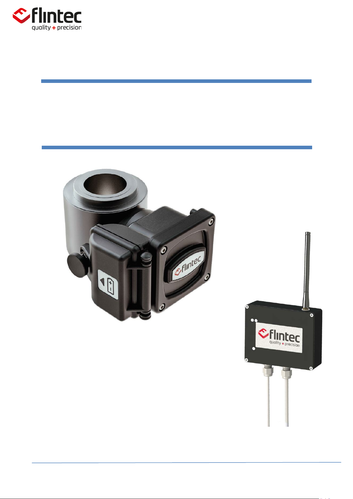
1. Product description
The CC1W is a wireless version of our CC1 pump off control load cell. The CC1W utilizes the same
proven design attributes as the CC1 - stainless steel, hermetic seal, fatigue rating and intrinsically safe
operation. The CC1W transmits polished rod load wirelessly which solves the industry wide problem
of cable failures. After months of development in the field, working hand in hand with end users, our
design addresses the most demanding concerns raised.
The CC1W technology sets our product apart from all wireless products currently available in the
market. The primary advantage we bring is extremely low power consumption. Despite the low
power consumption, the product can deliver a continuous flow of data, high signal strength and long
battery life. We also offer position sensing capability which is synchronized with the load
measurement. This eliminates the need for hall effect sensors or inclinometers and the costly
maintenance associated with each. The wireless enclosure also incorporates an independent
compartment for both the wireless technology and the battery. This allows for easy, single handed
access to the battery for replacement in the field. We carefully specified a pre-wired “D cell” battery
that is inexpensive and commercially available worldwide.
• Continuous flow of data: 100 readings per second
• Low power consumption: 12-18 month battery life
• High signal strength: +13dBm to +17dBm, 30-300 meter transmission
• HazLoc approved: UL rated for Class 1, Division 1 environments (see label for full approval)
• On-board position: +/-0.5% accuracy
• Security: Proprietary wireless transmission protocol
• Ease of use: independent battery access, commercially available battery
• Weatherproof: IP67 rating, rated for use in -70°F to 175°F (-55°C to 80°C)
Accessories:
Base/Receiver (included)
Antenna & Connection Cables (included)
Lithium Battery (Included)
Magnetic Mount or Post Mount for Base (user specified)
Load Spacer/Plate
Spherical Washer Set
Page 3 of 21 DOC No. 0095771

User Manual - CC1W
2. Mounting instructions
IMPORTANT
The employees responsible for the equipment installation and verification must take into
consideration all the actions concerning this subject specified in IEC 60079-14:2013 ed. 5.0
(Electrical installations design, selection and erection) standard. In addition to general
specifications associated with any system installed in hazardous locations, special attention
should be paid for specific requirements regarding intrinsic safety (section 12).
2.1 Base Unit
The “Base” (receiver) of the device comes with a magnet base for easy mounting on a metal
surface inside or outside of the pump controller cabinet. Base is mounting outside the hazardous
area and not intended to meet hazardous location safety standards.
Base Unit
Page 4 of 21 DOC No. 0095771
DIN rail mount
Pole mount with U-
User Manual - CC1W
When the magnet base is not directly attached due to non-metallic surface or space
constraint, the base can be suitable fastened to any structure using brackets, plates or other
type of support.
_________________________________________________________________
IMPORTANT
must be ensured.
You may optionally use an extension cable to mount the antenna.
In order to achieve the best performance a vertical alignment of the antenna
Page 5 of 21 DOC No. 0095771
User Manual - CC1W
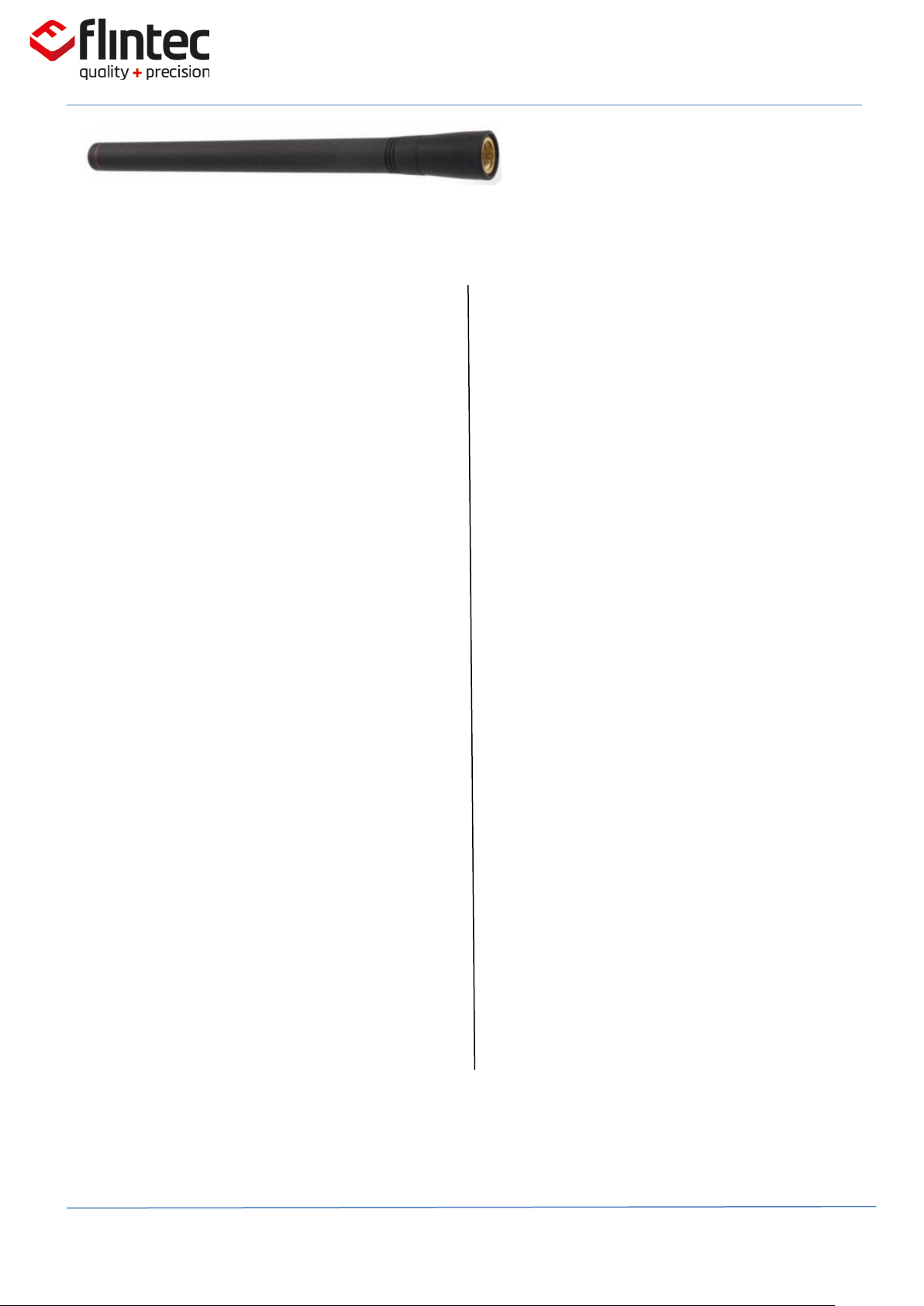
2.2 Antenna Recommendations
Omni Directional Antenna CC1W
base unit is equipped with an Omnidirectional antenna in order to provide
the widest possible signal coverage.
RP-SMA Connector (female)
The antenna is provided with a
threaded, weatherproof RP-SMA
female connector. This connector
must be properly tightened to the
male connector on the enclosur e .
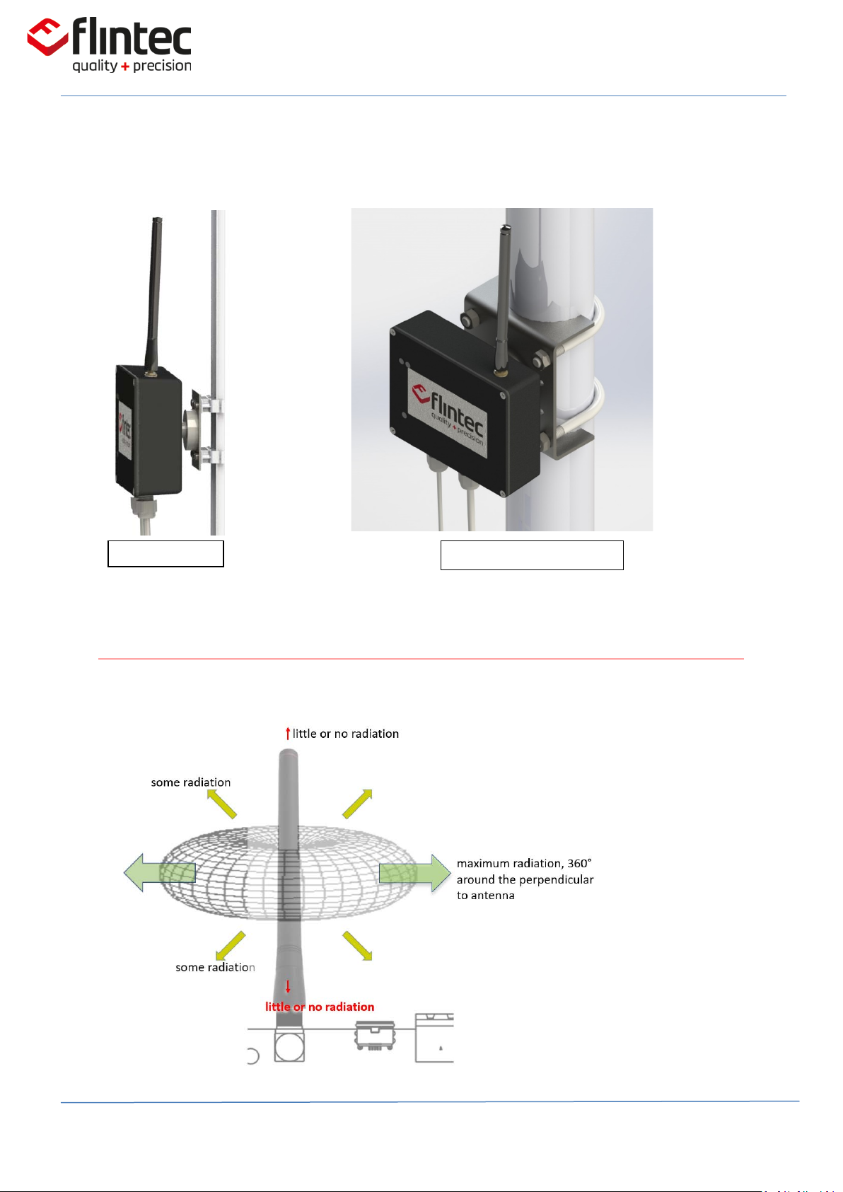
Vertical Alignment
In order to achieve the best
performance a vertical alignment
of the antenna must be ensured.
Line-of-sight
Is important to find, whenever
possible, a spot full line of sight
with the receptor where no
obstacles reside between the path.
Note: Fresnel Zone, the area around
the visual line-of-sight that radio
waves spread out into after they
leave the antenna must be clear or
the signal strength will be weakened
due to reflections.
Antenna Height
Taking advantage of the free
positioning of the base antenna,
a convenient place in height with
good clearance and away from
ground must be considered.
Note: The use of extension cables that
always represent attenuation and
signal strength losses should be
avoided if possible
Page 6 of 21 DOC No. 0095771
User Manual - CC1W
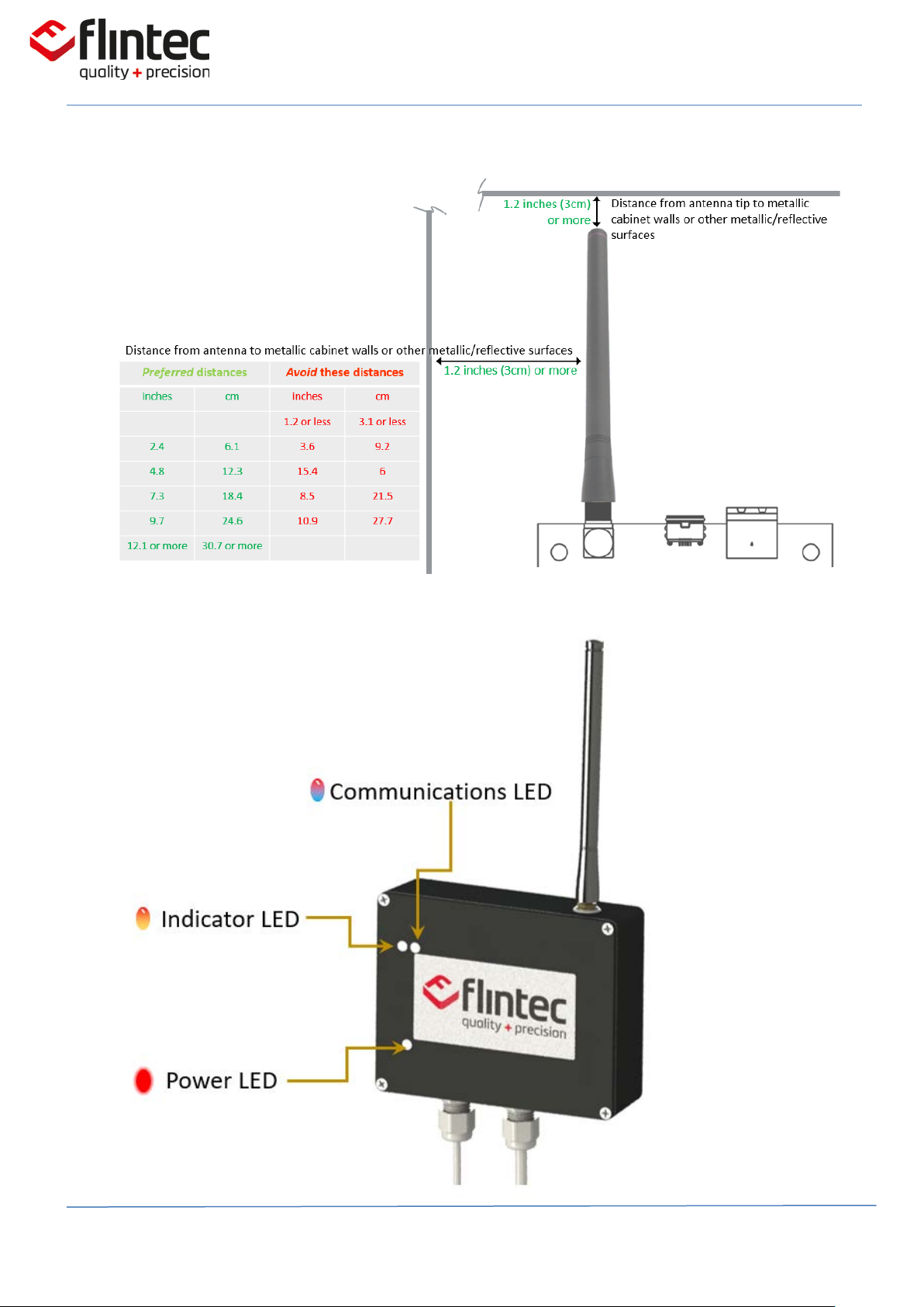
When mounting inside an enclosure
Page 7 of 21 DOC No. 0095771
 Loading...