

INSTALLATION AND
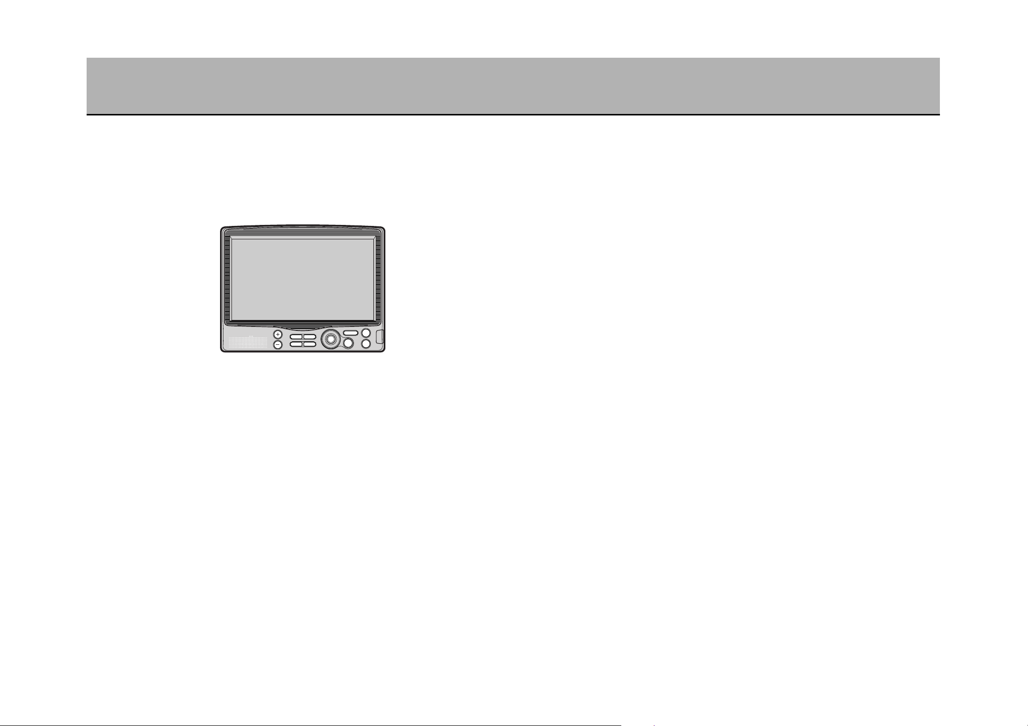
OPERATION MANUAL
Portable DVD Navigation System
Part No.:
NV-E7000
We would like to take this opportunity to sincerely thank you for purchasing
this product.
¡Read this manual and the warranty certificate carefully prior to using the unit. After
having completely read this manual, store it in a safe place for easy reference.
¡Make sure to read the “Safety precautions” and “Cautionary items for proper usage”
appearing within this manual.
21
OBLIGATIONS
In order to obtain warranty service, the product must be delivered to and picked up from an Authorized Sanyo
Factory Service Center at the user’s expense, unless specifically stated otherwise in this warranty. The names
and addresses of Authorized Sanyo Service Centers may be obtained by calling the toll-free number listed below.
This warranty is valid only on SANYO products purchased and used in the united states of america,
excluding all U.S. Territories and protectorates. THIS WARRANTY APPLIES ONLY TO THE ORIGINAL
RETAIL USER, AND DOES NOT APPLY TO PRODUCTS USED FOR ANY INDUSTRIAL, PROFESSIONAL
OR COMMERCIAL PURPOSE. THE ORIGINAL DATED BILL OF SALE OR SALES SLIP MUST BE
SUBMITTED TO THE AUTHORIZED SANYO SERVICE CENTER AT THE TIME WARRANTY SERVICE IS
REQUESTED.
Subject to the OBLIGATIONS above and EXCLUSIONS below, SANYO FISHER COMPANY (SFC) warrants
this SANYO product against defects in materials and workmanship for the periods specified below. SFC will
repair or replace (at its option) the product and any of its parts which fail to conform to this warranty. The
warranty period commences on the date the product was first purchased at retail.
For product operation, authorized service center referral, service assistance or problem resolution, call
CUSTOMER INFORMATION 1-800-421-5013
Weekdays 8:00 AM - 5:00 PM Pacific Time
For accessories and/or parts not available from an authorized dealer, call
PARTS ORDER INFORMATION 1-800-726-9662
Weekdays 8:00 AM - 5:00 PM Pacific Time
EXCLUSIONS
This warranty does not cover (A) the adjustment of customer-operated controls as explained in the
appropriate model’s instruction manual, or (B) the repair of any product whose serial number has been
altered, defaced or removed.
This warranty shall not apply to the cabinet or cosmetic parts, knobs or routine maintenance.
This warranty does not apply to uncrating, setup, installation, removal of the product for repair or reinstallation
of the product after repair.
This warranty does not apply to repairs or replacements necessitated by any cause beyond the control of
SFC including, but not limited to, any malfunction, defect or failure caused by or resulting from unauthorized
service or parts, improper maintenance, operation contrary to furnished instructions, shipping or transit
accidents, modification or repair by the user, abuse, misuse, neglect, accident, incorrect power line voltage,
fire, flood or other Acts of God, or normal wear and tear.
The foregoing is in lieu of all other expressed warranties and SFC does not assume or authorize any party to
assume for it any other obligation or liability.
THE DURATION OF ANY WARRANTIES WHICH MAY BE IMPLIED BY LAW (INCLUDING THE
WARRANTIES OF MERCHANTABILITY AND FITNESS) IS LIMITED TO THE TERM OF THIS WARRANTY.
IN NO EVENT SHALL SFC BE LIABLE FOR SPECIAL, INCIDENTAL OR CONSEQUENTIAL DAMAGES
ARISING FROM OWNERSHIP OR USE OF THIS PRODUCT, OR FOR ANY DELAY IN THE PERFORMANCE
OF ITS OBLIGATIONS UNDER THIS WARRANTY DUE TO CAUSES BEYOND ITS CONTROL.
SOME STATES DO NOT ALLOW LIMITATIONS ON HOW LONG AN IMPLIED WARRANTY LASTS
AND/OR DO NOT ALLOW THE EXCLUSION OR LIMITATION OF CONSEQUENTIAL DAMAGES, SO THE
ABOVE LIMITATIONS AND EXCLUSIONS MAY NOT APPLY TO YOU.
THIS WARRANTY GIVES YOU SPECIFIC LEGAL RIGHTS. YOU MAY HAVE OTHER RIGHTS, WHICH
VARY FROM STATE TO STATE.
For your protection in the event of theft or loss of this product, please fill in the information below for your own
personal records.
Model No. Serial No.
(Located on back or bottom side of unit)
Date of Purchase Purchase Price
Where Purchased
SANYO MOBILE AUDIO
MODEL NV-E7000 LIMITED WARRANTY
LABOR
1 YEAR
PARTS
1 YEAR
WARRANTY APPLICATION
New, unused Sanyo Audio/Video products
purchased through a Sanyo authorized dealer
in Canada are warranted against manufacturing
defects in materials and workmanship for ONE
YEAR from the date of purchase by the original
retail purchaser.
This warranty only applies in favor of the
original retail purchaser of the warranted
product.
SANYO CANADA INC.’S
RESPONSIBILITY
During the warranty period, SANYO Canada
Inc. will repair, or at our option, replace an
Audio/Video product which shows evidence of a
manufacturing defect in materials or
workmanship. Replacement PARTS are
warranted for the remaining portion of the
warranty period.
WHAT IS NOT COVERED
(a) Products purchased outside Canada.
(b) Products purchased in a used condition.
(c) Problems due to product set-up and
installation.
(d) Adjustments that are outlined in the
Operating Manual.
(e) Accessory items including antenna,
batteries, cassette tapes, cables, etc.
(f) Damage in or due to transportation.
(g) Damage due to improper maintenance,
improper wiring, accident, abuse, misuse or
negligence.
(h) Damage caused by lightning and power
surges.
ORIGINAL RETAIL PURCHASER’S
RESPONSIBILITY
You, the original retail purchaser, must present
your original, dated bill-of-sale together with this
warranty to SANYO Canada Inc. or to an
authorized Sanyo Service Depot when you
make a claim under this Warranty.
You, the original retail purchaser, are
responsible for any costs of TRANSPORTING
the product to and from SANYO Canada Inc. or
an authorized Sanyo Service Depot. You also
are responsible for the cost of any
MAINTENANCE necessary in respect of the
product.
WARRANTY BECOMES VOID
This warranty becomes void if the product’s
serial numbers are altered or removed or if any
repair to the product is made other than by
SANYO Canada Inc. or by an authorized Sanyo
Service Depot.
LIMITATIONS
(a) SANYO Canada Inc. reserves the right to
change or improve the design of the model
of the product warranted hereunder without
incurring any obligation to make any
modifications to or to install any
improvement in or on the product.
(b) In no event shall SANYO Canada Inc. or
any of its Authorized Dealers be liable for
special or consequential damage arising
from the use of this product.
STATUTORY WARRANTIES
The above provisions do not preclude the
operation of any applicable provincial statute
which in certain circumstances may not allow
some of the limitations and exclusions
described in this Warranty. Where any terms of
this Warranty are prohibited by such a statute,
they shall be deemed null and void but the
remainder of this warranty shall remain in
effect.
HOW TO OBTAIN WARRANTY
SERVICE
Please contact the Sanyo Authorized Dealer
from whom the product was purchased, or
contact us directly at:
SANYO Canada Inc.
1-300 Applewood Cres.
Concord, Ont. L4K 5C7
(905) 760-9944
1-800-263-2244
http://www.sanyocanada.com
THE SANYO COMFORT WARRANTY
AUDIO/VIDEO PRODUCTS
(R12)

43
CONTENTS (1)
WARRANTY ........................................................................................................1
CONTENTS .........................................................................................................3
TIPS ON HOW TO READ THIS MANUAL...........................................................7
INSTALLATION MANUAL ...................................................................................9
HOW TO INSTALL THE UNIT ...........................................................................11
GPS EXTERIOR ANTENNA INSTALLATION METHOD ..................................14
INTRODUCTION ...............................................................................................18
SAFETY PRECAUTIONS ..................................................................................19
CAUTIONARY ITEMS FOR PROPER USAGE .................................................24
MAIN FEATURES..............................................................................................28
ABOUT DISCS...................................................................................................31
WHAT IS A NAVIGATION SYSTEM..................................................................34
ABOUT THE GPS EXTERIOR ANTENNA ........................................................36
COMPONENT NAMES AND FUNCTIONS (1)..................................................37
CHARACTER INPUT USING THE 10-KEY ON THE REMOTE CONTROL .....45
HOW TO HANDLE THE REMOTE CONTROL .................................................47
ABOUT THE POWER SOURCE .......................................................................50
INSERTING/REMOVING A DISC......................................................................52
NAVI OPERATION ............................................................................................54
DISPLAYING THE MAP SCREEN ...................................................................55
HOW TO VIEW THE MAP SCREEN .................................................................57
CHANGING THE MAP DISPLAY ......................................................................59
QUICK ROUTE SEARCH ..................................................................................66
BASIC MENU OPERATIONS ............................................................................68
LIST OF MENU ITEMS......................................................................................69
ABOUT THE QUICK MENU ..............................................................................70
SEARCHING FOR A GEOGRAPHICAL POINT................................................71
POINTS OF INTEREST CATEGORIES ............................................................82
REGISTERING YOUR HOME ...........................................................................84
ABOUT SETTING ROUTES .............................................................................85
SINGLE-ROUTE/MULTI-ROUTE SEARCH ......................................................89
MODIFYING A ROUTE......................................................................................96
DISPLAYING THE PRESENT ROUTE..............................................................99
STORING/DELETING THE PRESENT ROUTE..............................................100
VIEWING ROAD INFORMATION WITH THE PRESENT ROUTE..................102
SEARCHING FOR A WAY HOME...................................................................103
STOPPING/STARTING ROUTE GUIDANCE..................................................104
MODIFYING ROUTE CONDITIONS ...............................................................105
STRAYING OFF THE ROUTE (REROUTE)....................................................107
THE ROAD AHEAD CANNOT BE TAKEN (DETOUR SEARCH) ...................108
SAVED ROUTES LIST ....................................................................................109
ROUTE SIMULATION .....................................................................................112
CHANGING THE MAIN SCREEN SETTINGS ................................................113
SETTING THE 2-SCREEN DISPLAY..............................................................115
CHANGING THE ROUTE GUIDANCE SCREEN SETTINGS.........................118
INDICATING THE STREET NAME .................................................................122
CHANGING THE UNIT OF DISTANCE, THE COLOR OF
THE MAP AND THE PRESENT LOCATION MARK .......................................123
DISABLING THE REGISTERED POINT MARK DISPLAY..............................124
DISPLAYING LATITUDINAL AND LONGITUDINAL COORDINATES............125
CLOCK SETTING ............................................................................................126
USING TRACKS ..............................................................................................127
MODIFYING THE PRESENT LOCATION MARK LOCATION
AND BEARING ................................................................................................131
EDITING/VIEWING REGISTERED POINTS ...................................................133
RETRIEVING REGISTERED POINT MAPS ...................................................136
DELETING REGISTERED POINTS ................................................................137
VIEWING GPS INFORMATION.......................................................................138
VERIFYING UNIT CONNECTION ...................................................................139

65
CONTENTS (2)
DVD/CD/JPEG IMAGING OPERATION .........................................................140
TO START PLAYBACK ...................................................................................141
VARIOUS PLAYBACK FUNCTIONS...............................................................143
HOW TO USE THE TITLE MENU ...................................................................145
HOW TO USE THE DVD MENU .....................................................................146
PLAYBACK FROM THE DESIRED POSITION ..............................................147
SWITCHING THE AUDIO LANGUAGE...........................................................149
SWITCHING THE SUBTITLE LANGUAGE .....................................................150
CHANGING THE ANGLE ................................................................................151
ENLARGING THE SCREEN............................................................................152
SWITCHING THE AUDIO................................................................................153
SHUFFLED PLAYBACK ..................................................................................154
PLAYING BACK TRACK INTROS...................................................................155
REPEAT PLAYBACK.......................................................................................156
SWITCHING THE TIME DISPLAY ..................................................................157
VIEWING JPEG IMAGES ................................................................................158
ENLARGING/REDUCING THE IMAGE DISPLAY...........................................160
CHANGING THE SLIDESHOW DISPLAY FORMAT ......................................161
SELECTING PLAY MODE...............................................................................162
ROTATING THE IMAGE..................................................................................163
CHANGING THE INITIAL SETTINGS .............................................................164
TERMINOLOGY ..............................................................................................174
OTHER ............................................................................................................176
CONNECTING A VIDEO DECK/VIDEO CAMERA..........................................177
HOW TO ADJUST THE IMAGE ......................................................................178
ABOUT THE AUTOMATIC BRIGHTNESS ADJUSTMENT FUNCTION .........181
ABOUT THE BRIGHTNESS OF THE BUTTONS............................................181
MAIN SPECIFICATIONS .................................................................................182
RECEIVING SIGNALS FROM THE GPS SATELLITE ....................................183
CAUTIONARY ITEMS DURING ROUTE GUIDANCE.....................................185
ABOUT THE VOICE GUIDANCE ....................................................................189
ABOUT THE MAP DVD-ROM .........................................................................191
SETTING THE DEPARTURE/WAYPOINT/DESTINATION POINTS ..............193
ABOUT UPGRADES .......................................................................................195
TROUBLESHOOTING.....................................................................................197
WHEN THIS MESSAGE APPEARS... .............................................................204
NAVIGATION SYSTEM DEFAULT SETTINGS LIST ......................................205
7
TIPS ON HOW TO READ THIS MANUAL
This manual uses the following marks to call the user’s attention.
The meaning of each mark is provided below. Please make sure you
understand these prior to reading the manual.
Follow this advice to ensure proper functioning of your vehicle
and the unit.
Not doing so may result in damage to your vehicle or the unit
or result in a decreased level of performance.
Keep this hint in mind when using the unit.
It may be useful later on to help you operate it skillfully.
Indicates title names and page numbers for easy reference.
Displays the buttons on the remote control and on the unit itself.
Displays the menus (items) appearing on the screen.
CAUTIONARY ITEMS FOR PROPER USE
¡Operating the portable DVD navigation unit
• Avoid operating the unit while driving. First stop the vehicle and then proceed.
• While driving, keep your gaze on the unit’s screen to a bare minimum (under 1
second).
¡Installing the portable DVD navigation unit
• Install the unit on the upper part of the center panel in a way so as not to obstruct
your view of the road.
• Install it properly as per the instructions appearing in this manual.
(The unit is designed to render complex imaging such as videos impossible while
driving. Do not under any circumstance reconfigure the wiring or perform any
improper conversions to the unit.)
Hint
z
v
Advise
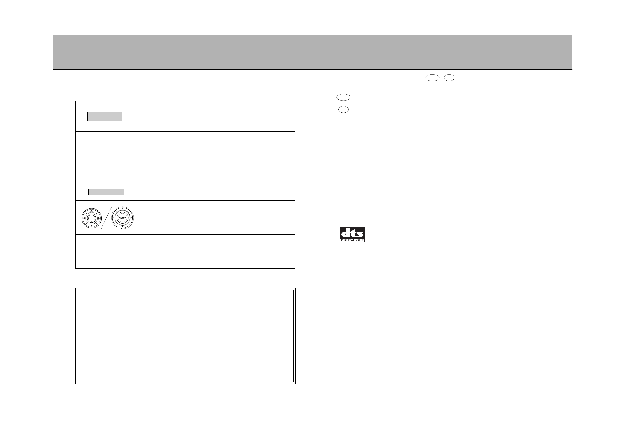
É
Moves the Joystick vertically and laterally and shows operation
in 8 different directions.
Describes operation results.
This symbol denotes that the operation procedures are divided
at the next step.
:
<
8
■ The meaning of the symbols ( , ) appearing in this manual are as
follows.
. . .
DVD video function
. . .
Music CD function
■ This unit utilizes the following 3 technologies to playback DVD videos:
Macrovision
This product incorporates copyright protection technology that is protected by method
claims of certain U.S. patents and other intellectual property rights owned by
Macrovision Corporation and other rights owners. Use of this copyright protection
technology must be authorized by Macrovision Corporation, and is intended for home
and other limited viewing uses only unless otherwise authorized by Macrovision
Corporation. Reverse engineering or disassembly is prohibited.
Dolby Digital
Manufactured under license from Dolby Laboratories.
“Dolby” and the double-D symbol are trademarks of Dolby Laboratories. Confidential
Unpublished Works. ©1992-1997 Dolby Laboratories, Inc. All rights reserved.
“DTS” and “DTS Digital Out” are trademarks of Digital Theater Systems, Inc.
DVD CD
DVD
CD
Route search
10
Please contact your place of purchase if you have any questions about installation
or connection.
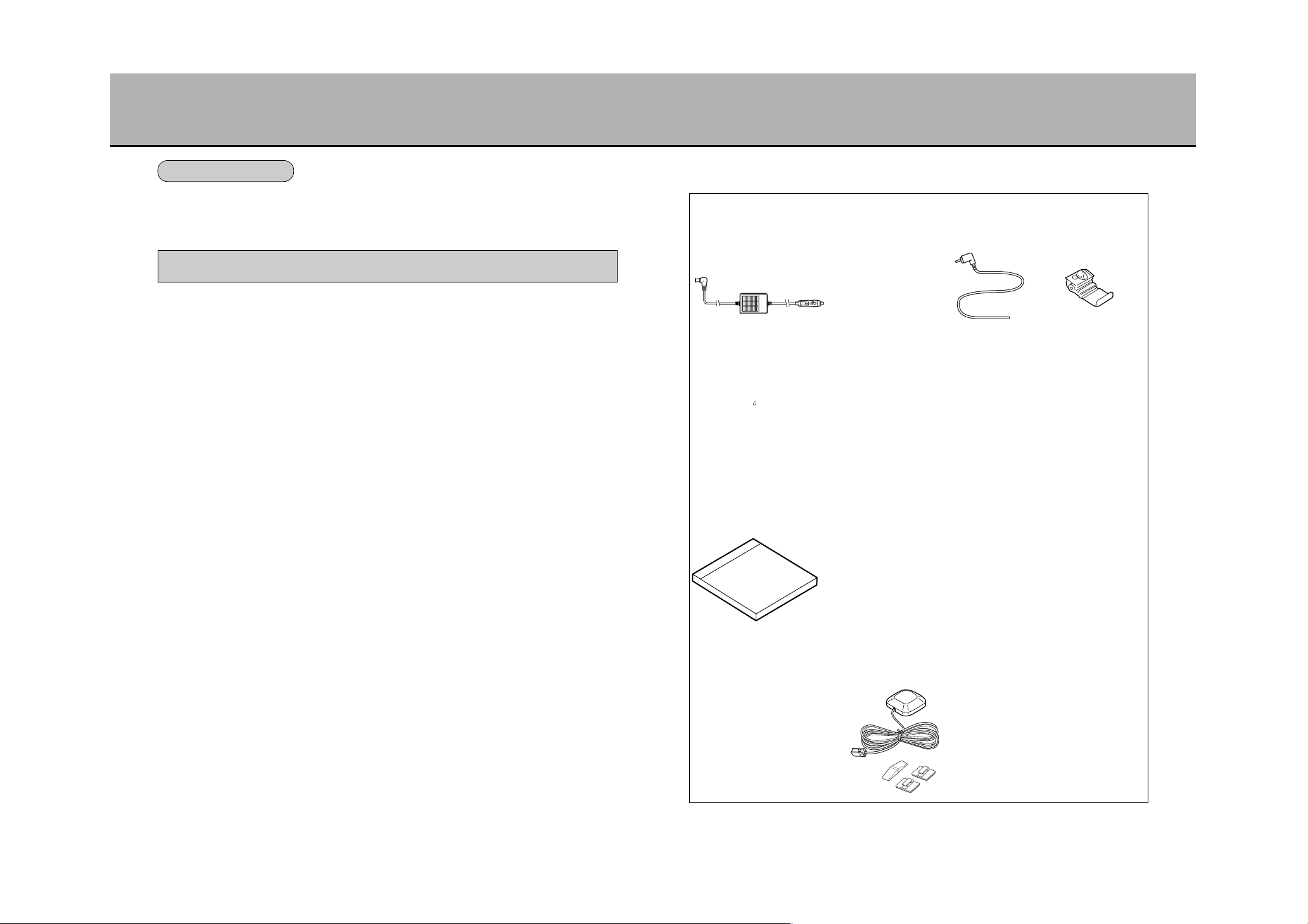
ACCESSORIES
9
INSTALLATION MANUAL
Parking brake
connector cable
GPS Exterior Antenna and
Installation Parts
1 disc
1 core
Map DVD-ROM
Self-lock connector
AC/DC adapter
2 clips2 cables
12V cigarette lighter
connector cable
1 cable 1 cable
Remote control and
holder
1211
■ The initial adhesive strength of the double-surface adhesive tape is reduced when the
temperature is low (20°C (68°F) or less). Turn on the heater and heat the vehicle up
prior to adhering onto the mounting surface.
■ Make sure to use the cleaner included with the kit to clean the mounting
surface of any dirt and let the surface dry before adhering the stand base.
The dashboard may have been coated with a wax surface protective agent that
is hard to see with the naked eye. This wax significantly weakens the doublesurface adhesive tape and may cause the unit to fall.
■ The double-surface tape adhering the stand base can only be stuck onto the
surface once and cannot be peeled off and re-adhered.
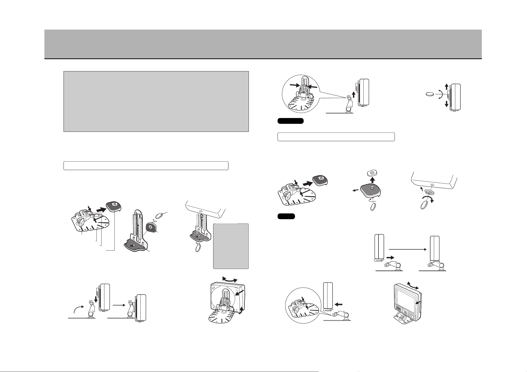
1
Stand assembly
q Method using the portable DVD navigation unit mounting stay
There are two ways to assemble the stand: with or without the portable DVD navigation
unit mounting stay. Select the assembly method that best suits your vehicle.
¡The back/forth left/right angles and the vertical positioning are adjustable.
1. Push the lock release tab
and remove the one-touch
attachable shoe.
4. Mount the unit prepared as described in 3 onto the
stand base.
2. Loosen the screw, slide the
slider nut through the center
groove of the portable DVD
navigation unit mounting
stay and tighten the screw.
3. Install the portable DVD
navigation unit mounting
stay onto the unit.
¡Adjust the angle.
¡The back/forth left/right angles are adjustable.
1. Push the lock release tab
and remove the onetouch attachable shoe.
2. Remove the slider nut from
the one-touch attachable
shoe.
3. Install the one-touch
attachable shoe onto the
unit.
4. Mount the unit prepared as described in 3 onto
the stand base.
¡Removing the portable DVD navigation unit
from the stand base
¡Adjust the vertical position
¡Adjust the angle.
¡Remove the unit from the stand base.
Disc replacement is impossible once the unit has been mounted onto the stay.
Replace the disc after removing the unit from the mounting stay.
CAUTION
HOW TO INSTALL THE UNIT (1)
PREPARATIONS PRIOR TO INSTALLATION
Press and
hold down
Angle setting screw
Pull out
Lock release tab
One-touch attachable shoe
Stand base
Loosen
Coin
Tighten
Slider nut
The rounded
part is vertical.
Portable DVD navigation
unit mounting stay
Tighten
Portable DVD
Navigation System
While pressing the
bottom of the unit,
apply the mounting
stay cushion onto the
back of the unit.
Applying excessive
force will cause the
disc insert slit cover to
warp which will make
it strike the disc.
CAUTION
Make the stand
perpendicular to
the base.
(see figure)
Slide the one-touch attachable
shoe down through the stand
base until you hear a snap.
Loosen the angle
setting screw and
adjust the back/forth
left/right angles.
After adjustment,
fasten the screw.
Press
and hold
down
Press the lock
release tab and
pull out the unit.
Remove the unit from the stand base and adjust
the position of the one-touch attachable shoe.
Pull out
Loosen
Tighten
After adjustment,
fasten the screw.
w How to mount directly onto the stand base
Loosen the angle
setting screw and
adjust the back/forth
left/right angles.
After adjustment,
fasten the screw.
Press and hold down
Pull out backwards
Pull the unit
backwards while
pressing the lock
release tab.
Slide the one-touch
attachable shoe down
through the stand base
until you hear a snap.
Tighten
Front
Front
Loosen
Slider nutPull out
Press and
hold down
Keep the removed slider nut in a safe place.
It will be necessary when using the portable DVD navigation unit mounting stay.
NOTE
1413
NOTE
After having adhered the stand base, remove the portable DVD
navigation unit and leave the stand base as is for at least 24 hours.
Immediately after adhering to the surface, the adhesion strength may be
too weak to ensure a firm hold.
* Depending on the shape/material of the dashboard, the double-surface adhesive tape alone
may not have sufficient adhesive strength. Use the tapping screws included with the unit (4
screws) and securely anchor the unit.
(*In such a case, holes must be made into the dashboard. Exercise caution.)
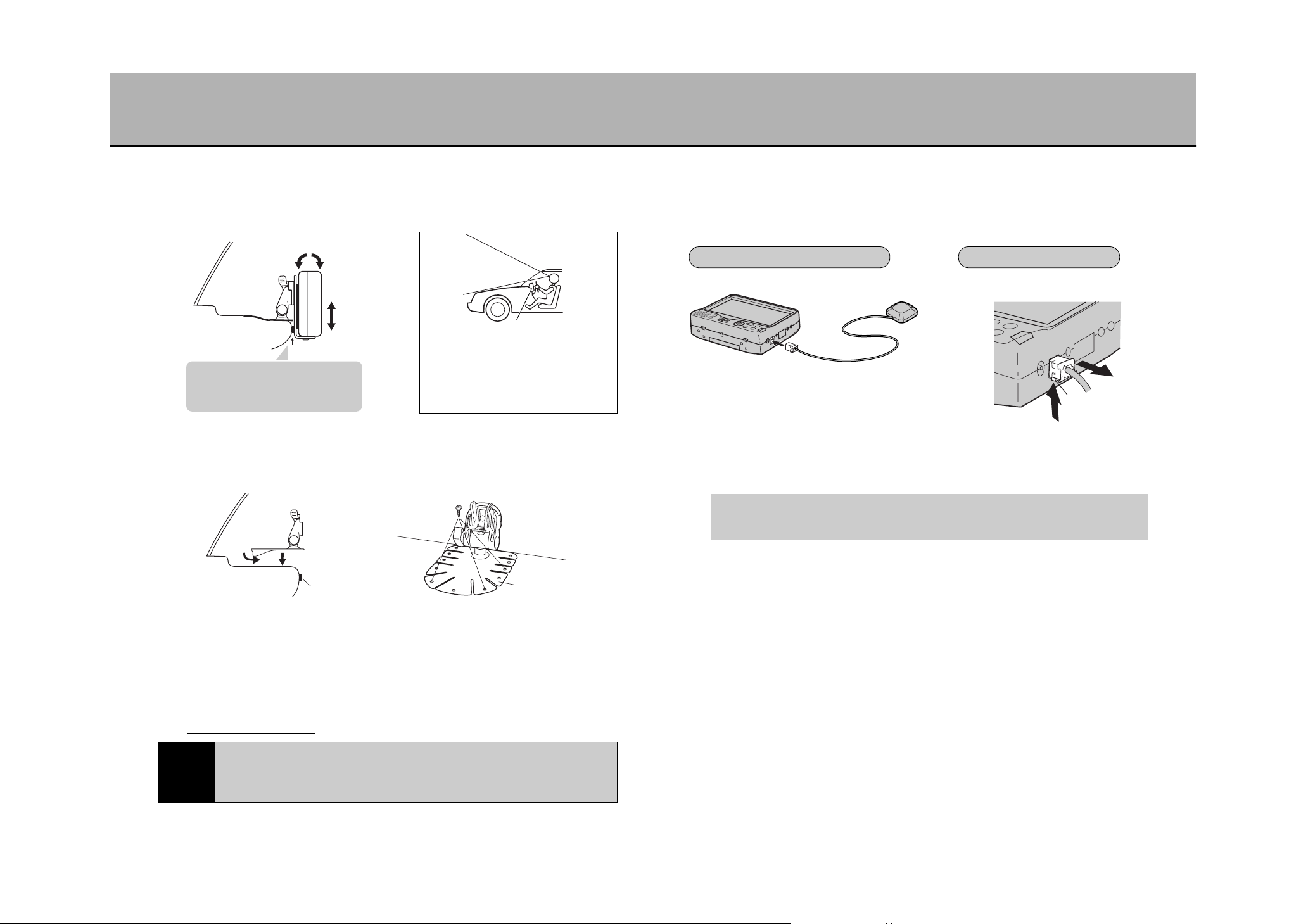
2
Determine the installation position
Look from the driver’s seat and verify
that the unit is not obstructing the view of
the road. Change the mounting area
should the unit block the view.
tWARNING
Press the tab and remove.
HOW TO INSTALL THE UNIT (2)
GPS EXTERIOR ANTENNA INSTALLATION METHOD (1)
Determine a position for mounting the unit onto the dashboard that renders it
easy to view. Bend and flex the adhesive surface of the stand base to
correspond to the curves of the dashboard.
3
Install the stand
Remove the unit from the stand base once, remove the blue sheet from the back
of the stand base, place the stand onto the desired mounting area (dashboard)
and apply pressure.
Fix the cushion included with the unit
where the unit mounting stay and the
dashboard come into contact.
(Example: when using the mounting stay)
Cushioning material
Portable DVD
Navigation System
Portable DVD Navigation System
4
Mounting the portable DVD navigation unit
* Tightly fasten the affixing screws for each part of the stand. Not tightening
enough may cause the unit to change the installation angle or fall over due to
the vehicle’s vibrations.
1
Connect the antenna to the portable DVD navigation unit
The GPS exterior antenna must be connected in order to use the unit as a navigator.
Not doing so will render present geographic location determination impossible.
Cushioning material
Stand base
Stand base
Remove
Dashboard
* Tapping screw
(M3 x 8)
INSTALLATION METHOD REMOVAL METHOD
To the GPS exterior
antenna terminal
Tab
2
Installing onto the exterior chassis (see 15 page)
Installing the antenna in the vehicle interior may render proper electromagnetic
wave reception impossible.
It is preferable to install it onto the exterior chassis.
Install horizontally onto an area that will ensure that the chassis will not obstruct
electromagnetic wave reception (vehicle exterior or the front of the dashboard.)
* To ensure a firm installation, make sure to mount on a flat surface of the chassis.
Refer to page ?? for the angle and
vertical position adjustment method.

1615
INSTALLATION EXAMPLE
¡Pull the wire through the vehicle interior and take it out through the trunk.
¡Pass the antenna cord through the waterproof packing and adhere it in an area where it
is in contact with the vehicle’s waterproof rubber.
¡Affix cord clips if necessary.
¡Install the GPS exterior antenna horizontally onto a flat metal surface of the vehicle’s
exterior chassis.
Taking the antenna out from the trunk
¡Pull the wire through the vehicle interior and take it out from the driver’s seat.
¡Affix cord clips if necessary.
¡Install the GPS exterior antenna horizontally onto a flat metal surface of the vehicle’s
exterior chassis.
If taking the antenna outside from the driver’s seat

17

INTRODUCTION
18
I
N
T
R
O
D
U
C
T
I
O
N
SAFETY PRECAUTIONS ..................................................................................19
CAUTIONARY ITEMS FOR PROPER USAGE .................................................24
MAIN FEATURES..............................................................................................28
ABOUT DISCS...................................................................................................31
WHAT IS A NAVIGATION SYSTEM..................................................................34
ABOUT THE GPS EXTERIOR ANTENNA ........................................................36
COMPONENT NAMES AND FUNCTIONS (1)..................................................37
CHARACTER INPUT USING THE 10-KEY ON THE REMOTE CONTROL .....45
HOW TO HANDLE THE REMOTE CONTROL .................................................47
ABOUT THE POWER SOURCE .......................................................................50
INSERTING/REMOVING A DISC......................................................................52
2019
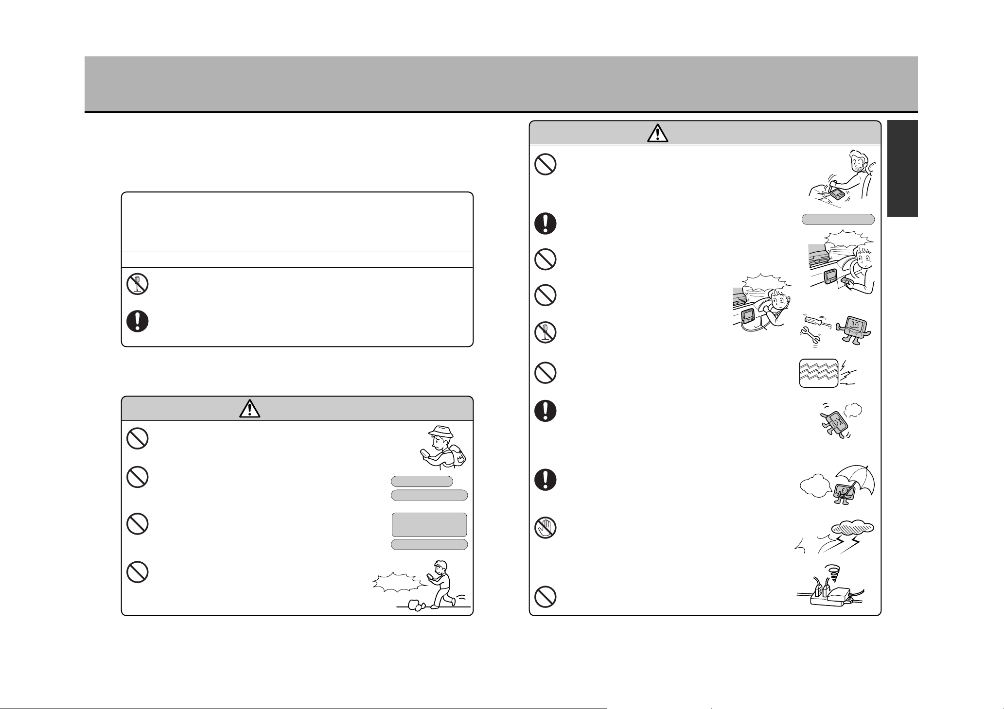
SAFETY PRECAUTIONS (1)
Do not use the unit as a maritime or aviation navigation
system or as a map for mounting climbing.
Use only the specified power source
(shown on the right). Do not use with a 24V vehicle
battery (truck, bus).
This may cause fires or electric shocks.
Use only the specified power cord (shown on the right).
Do not remodel or reconstruct the cord
This causes fires.
Do not view the navigation maps, DVDs or videos while
walking.
Use the unit only when standing still in a safe place.
Not doing so may cause accidents or injury.
120V AC power source
12V vehicle battery
: eThis symbol is to prohibit certain actions by the operator. The following
illustration will contain a specific warning message (the figure on the left
prohibits dismantle ).
: wThis symbol is to indicate certain actions for the operator. The following
illustration will contain a specific message (the figure on the left is a common
example).
¡To ensure proper usage of the unit, read this instruction manual prior to use.
¡After having read it, keep in a safe place for quick reference.
Indications appearing both in this manual as well as on the unit itself contain cautionary
items to ensure that the unit is used safely in order to prevent the operator or others nearby
from being harmed or injured.
The message following this symbol involves the likely possibility of
serious injury or even loss of life.
The message following this symbol involves the possibility of injury
or material damage.
tWARNING:
tCAUTION:
The content of warning messages may also depicted as illustrations.
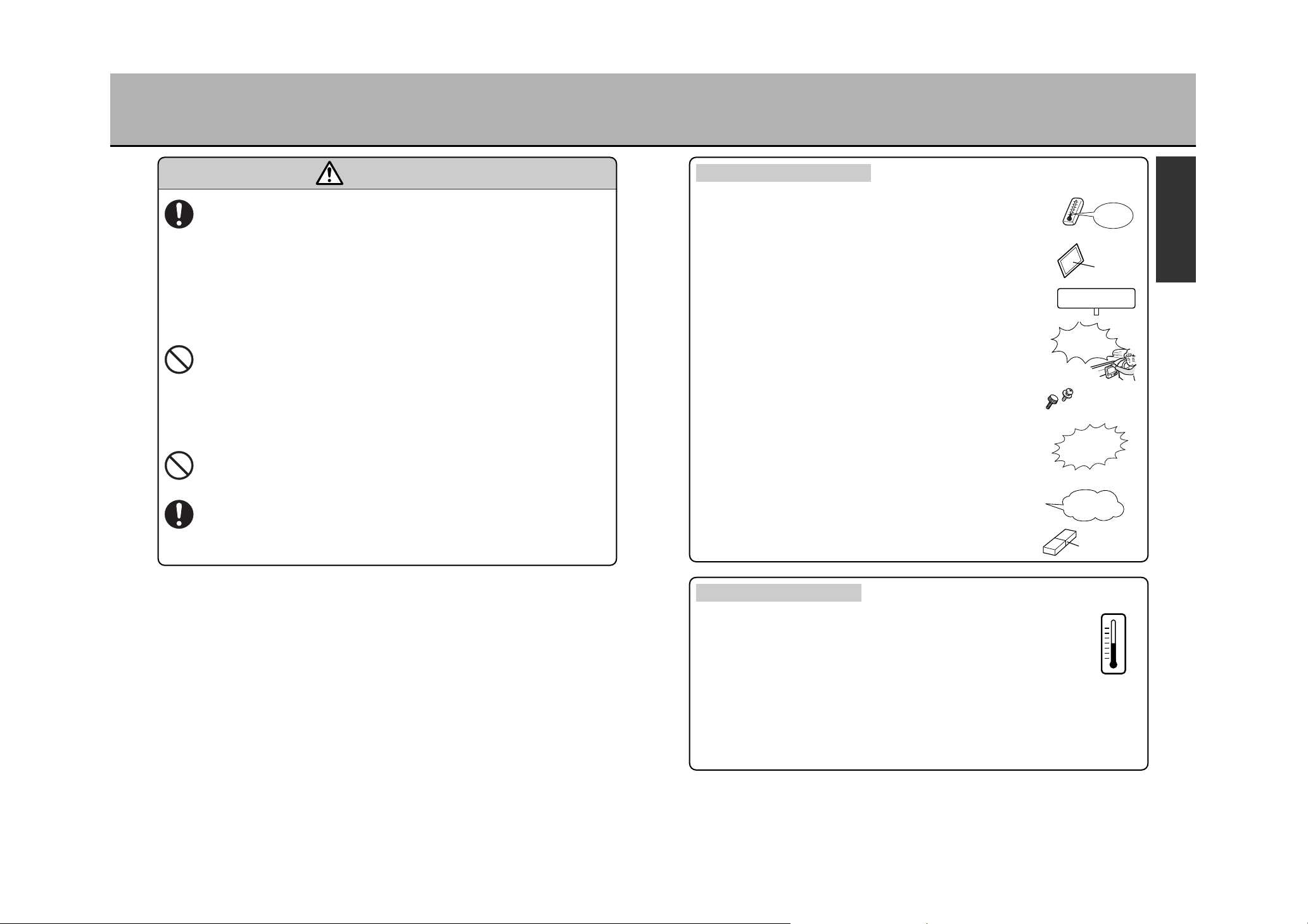
WARNING
Do not place or install the unit in an area that would
hinder the view of the road, obstruct driving operations
(such as steering, shifting or breaking), pose a danger to
passengers or obstruct the deployment of the airbag
system. Otherwise, traffic accidents or injury may result.
If using the unit as an automobile navigator, use the
included installation kit and securely affix the unit.
Otherwise, traffic accidents or injury may result.
Do not operate the unit or replace discs while driving.
Do so only after having stopped the vehicle in a safe place.
Otherwise, traffic accidents may result.
Do not use headphones while driving.
Traffic accidents may result.
Do not dismantle or remodel the unit.
Accidents, fires or electric shocks may result.
Do not use the unit if malfunctions occur such as if no
image is displayed or if no sound is emitted.
Accidents, fires or electric shocks may result.
In the event of foreign object infiltration into the unit,
water or beverage splashing onto the unit, smoke or a
strange smell coming from the unit or other abnormality,
immediately stop using the unit and consult the place of
purchase. Using the unit after such occurrences may cause
accidents, fires or electric shocks.
Exercise caution so as to not let the unit get wet nor let
water infiltrate into the unit (especially when using
during rain, snowfalls, near the coastline or near a body
of water). Fires or electric shocks may result.
Do not touch the antenna or the power supply plugs
when lightning is heard. However, when lightning is
heard from afar, immediately unplug the AC/DC adaptor
to avoid being struck by lightning. (If using outdoors,
immediately retract the antenna and stop using the unit.)
Fires or electric shocks may result.
Do not use a multi-connection plug.
Fires or overheating may result.
WARNING
Do not
dismantle
Do not
touch
Included AC/DC adaptor
Included 12V
automobile cigarette
lighter connection cable
Dangerous
Rock
Included installation kit
Dangerous
Dangerous
Yang!
Yang!
I hate
rain!
Flash!
Bang!
I
N
T
R
O
D
U
C
T
I
O
N
2221
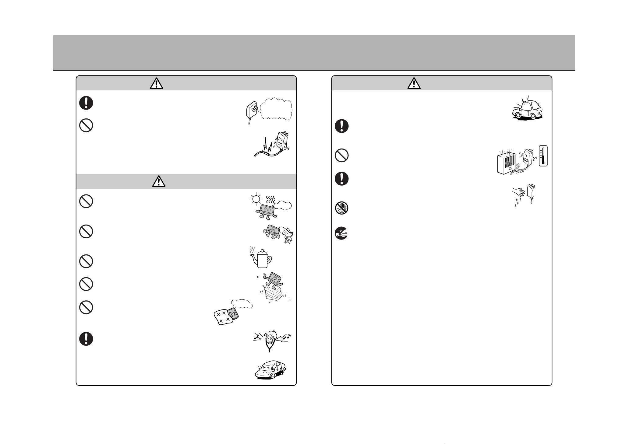
SAFETY PRECAUTIONS (2)
CAUTION
Make sure that there is no dust adhering to the metal
contacts of the AC/DC adaptor. Dust or metal touching the
contacts may result in fires or electric shocks.
Do not damage, bend excessively, twist, pull or place
heavy weights on the AC/DC adaptor cord.
Should the cord get damaged (core wire exposed, cut, etc.)
request a replacement at the place of purchase. Using as is
may result in fires or electric shocks.
WARNING
Do not use the unit in areas of high temperatures for an
extended period (direct sunlight, in a vehicle under a hot
sun, etc.) and do not leave the unit in such areas.
Burns or fires may result.
Do not place or install the unit in areas where rain is
blown in by the wind or in areas prone to water splashes,
humidity or dust. Water, humidity or dust infiltrating the unit
may result in smoke emissions or fires.
Do not place the unit in areas where it may be exposed to
oil, smoke or water vapor such as near a kitchen counter
or a humidifier. Fires or electric shocks may result.
Do not place the unit on unsteady or inclined surfaces.
It may fall resulting in injury.
Do not use the unit if it is covered by a cloth
sheet or blanket. Fires may result.
Enjoy watching the unit at a suitable sound level.
High volumes may damage your hearing and, because
exterior sounds become muffled, traffic accidents may result.
If the unit’s power supply is the vehicle battery, do not
leave the vehicle engine turned off for extended period
while operating the unit.
The vehicle battery may weaken and die out.
While driving, adjust the volume of the unit so that
exterior sounds can be heard well. Driving without being
able to hear exterior sounds may lead to traffic accidents.
Should the instructions provided by the navigation unit
differ from the actual traffic conditions, proceed to drive
in accordance with the actual traffic conditions.
Accidents may result.
Do not place the AC/DC adaptor cord near a heater.
The cord’s plastic sheath may melt and result in fires or
electric shocks.
When unplugging the AC/DC adaptor cord, do so by
pulling on the plug itself, not the cord.
Pulling on the cord may result in damage to the cord and lead
to fires or electric shocks.
Do not handle the AC/DC adaptor cord with wet hands.
Electric shocks may result.
When cleaning the plug or when not using the unit for an
extended period, disconnect the AC/DC adaptor from the
power supply for safety.
Electric shocks or fires may result.
Do not place the plug on the floor with the metal contacts
facing upward.
Stepping on it in this condition may cause injury.
Do not look directly at the laser light source.
Doing so may cause eye damage.
Do not press on the liquid crystal panel with excessive
force or expose it to impacts.
The liquid crystal panel glass may crack resulting in injury.
Should the liquid crystal panel crack, do not come into
contact with the liquid coming from the interior of the
panel. This may lead to inflammation of the skin.
¡Should the liquid be accidentally ingested, see a doctor
immediately.
¡Should the liquid get into the eyes or onto the skin, wash out
with a large amount of water and see a doctor immediately.
CAUTION
Pull out
the plug
23 24
SAFETY PRECAUTIONS (3)
For safety, adhere the stand base onto a surface that would enable secure
anchoring. Depending on the dashboard material (PP: polypropylene or
other), the double-surface adhesive tape alone may not be strong enough
to affix the unit. Use the tapping screws included with the unit (4 screws)
to securely anchor it.
* For such a case, holes need to be made into the dashboard. Proceed with
caution.
(*In case of a prominent curved surface, the adhesive area is reduced
resulting in unsteady mounting. The unit may not be mountable onto such a
surface.)
For vehicles equipped with airbags (SRS Dual Airbag, SRS Side Airbag,
SRS Curtain Airbag, etc.), do not under any circumstance install the unit
in a way that obstructs the airbag cover or would hinder its proper
operation. Do not wire the antenna cord in such an area.
In the event the airbag is to be deployed, it may not function correctly.
(*Decide on the unit’s mounting position after thoughtful consideration for safety
and consultation with the place of purchase.)
If the surface on which the unit is to be adhered is not plastic (leather,
wood, upholstery, etc.), the surface finish may become damaged
rendering installation using adhesives impossible.
Should the stand base adhesive get torn off the dashboard, slowly and
carefully peel it off the surface.
Because strong adhesive tape is used, peeling off with excessive force may
damage the dashboard surface finish.
CAUTION
CAUTIONARY ITEMS FOR PROPER USAGE (1)
¡The adhesive strength of the double-surface tape decreases at
low temperatures (20°C (68°F) or less). Adhere the unit onto the
dashboard after having increased the temperature using the
vehicle heater.
¡Adhere the unit after having cleaned off any dirt from the
mounting surface using the cleaning solution included with the
unit and let dry.
¡Once the double-surface adhesive tape is peeled off, it
cannot be re-adhered.
¡After installation, periodically check if the tape is still holding well.
¡Tightly fasten the screws affixing each part of the stand.
¡Do not mount the portable DVD navigation unit immediately
after having adhered the stand base to the mounting
surface. Leave the stand base as is without the unit
mounted for at least 24 hours after adhering it to the
dashboard.
¡Apply pressure onto the mounting surface by pressing on the
stand base after having adhered it to the dashboard.
¡The cushion included with the unit is used to keep the unit from
vibrating. Install it as per the instructions in the manual.
WHEN INSTALLING THE UNIT
It’s cold!
Use the
cleaner!
You only get one
chance to stick it on!
Check the
adhesion
quality!
Fasten the
screws tightly
Let it sit for at
least 24 hours
Apply lots
of pressure
Use the cushion
¡The unit may not function properly in extreme cold or extreme hot
conditions. Bring the ambient temperature back to normal to ensure
proper operation.
¡Do not leave the unit in areas of high temperatures (direct sunlight or in a
vehicle under the hot sun) or low temperatures (outdoors in cold weather).
Damage and deformation may result.
¡When the temperature exceeds 50°C (122°F), the unit automatically cuts
off the power supply to prevent damage to the liquid crystal display. After
having returned to the standard usage temperature range (0°C (32°F) to
50°C (122°F) when in NAVI/VIDEO mode), turn on the power supply and
normal operation will be possible.
ABOUT THE TEMPERATURE
I
N
T
R
O
D
U
C
T
I
O
N

2625
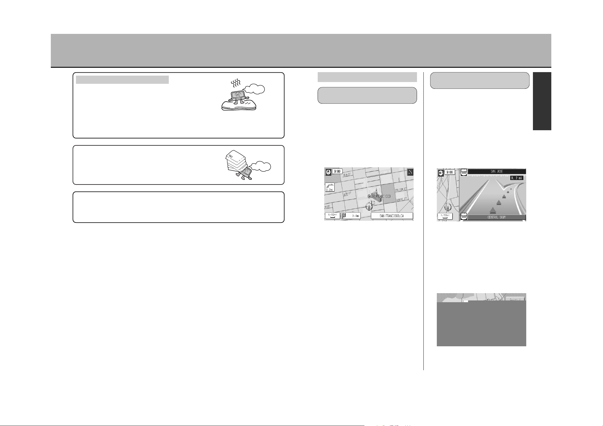
CAUTIONARY ITEMS FOR PROPER USAGE (2)
During raining days, when the humidity level
is high or immediately after having turned on
the heater in cold temperatures, condensation
(water drops) may form on the optical lens
inside the unit. Using the unit in this condition
may result in laser malfunction rendering
normal operation impossible. Results may
depend on the ambient environmental conditions,
however, the condensation will evaporate and normal operation will be possible after
removing the disc and leaving the unit unused for roughly 1 hour.
ABOUT CONDENSATION
Take out the
disc and
wait about 1
hour, ok?
Exposing the unit to vibrations may result in the following conditions:
¡DVD video/CD/JPEG imaging: Sound and image disturbance, however, both return to
normal when vibrations cease.
¡Map disc: Rarely affected by vibrations, however, on rare occasions, symptoms such
as the map disappearing from the screen may occur. Operation returns to
normal when vibrations cease.
ABOUT VIBRATIONS
Everything will
be back to
normal when
vibrations stop!
¡Direct sunlight will cause the display to blacken
due to reflection of the sunrays. Avoid direct
sunlight.
¡The display is best viewed from directly in front of
the unit. Watch the screen within a 45° angle
vertically and a 90° angle laterally from the unit.
¡Red and blue points of light may appear in the display. This is normal for a liquid
crystal display and does not mean the display is damaged.
¡The display uses a small fluorescent tube as a backlight for liquid crystals. If the
screen goes black and does not light up, consult the place of purchase.
ABOUT THE DISPLAY
45° vertically
90° laterally
Because the most detailed map reduction scales provided by the map disc vary
depending on the region, when moving the map screen to a region of varying reduction
scale, the screen may not show a map. Continue moving the map to return the normal
driving map screen and the reduction scale will change to the most detailed map for the
region presently displayed.
ABOUT THE DETAILED MAP SCREEN DISPLAY
Using the unit when the vehicle engine is turned off may lead to
weakening of the battery. Do not use the unit for an extended period
with the engine turned off.
ABOUT USING THE UNIT WITH THE VEHICLE ENGINE TURNED OFF
(WHEN THE UNIT POWER SOURCE IS THE VEHICLE BATTERY)
¡Dust easily adheres to the screen necessitating
periodical cleaning. When cleaning, cut off the
power supply and wipe the screen with a soft
cloth. Do not use a wet cloth and do not rub the
screen with a hard object or hit the screen.
2827
CAUTIONARY ITEMS FOR PROPER USAGE (3)
MAIN FEATURES (1)
The unit shows you the way just by
selecting a destination point.
By registering the location of your home
and pressing the Ç button, the
navigation unit will show you the
recommended route from your present
location to your home or destination.
zSee p.103, “Searching for a way home”.
Search for your destination by
entering the address and telephone
number.
NAVIGATION
The route is displayed right up to
your destination.
Vocally guides you in an accurate
and easy to understand way.
(Voice guide)
Enlarges highway junctions.
(Junction guide)
zSee p.115 and 116, “Display Intersection
Enlargements”.
3 route selections displayed
(Multiple route search)
The navigation unit finds different routes
with different conditions leading to your
destination. Routes prioritizing Faster
Route, Shorter Route or Optimal are found
simultaneously.
zSee p.89, “SINGLE-ROUTE/MULTI-
ROUTE SEARCH”.
* The distance and required time are displayed
as a guide. These may differ from the actual
conditions.
¡Do not use for an extended period on a blanket,
rug, carpet, cushion or other object that
obstructs the proper release of heat. Heat will
get trapped in the unit and lead to damage.
ABOUT THE INSTALLATION AREA
¡Do not let urethane or rubber made sheets or vinyl articles come into contact with the
unit for extended periods. This may lead to the paint falling off the cabinet or panel
surface and lead to a deterioration of the visual appearance.
Do not place heavy objects such as a golf bag on
top of the unit or hit the unit with such objects. This
may cause the case to crack and lead to breakage
as well as malfunctions.
It’s hot!
Heavy
Please be advised that SANYO will not assume any responsibility whatsoever for any
troubles arising from mishandling the unit as a result of not following the cautionary
items described within this manual. The unit is not guaranteed for troubles arising form
improper handling or using the unit in a way contrary to conventional wisdom.
GUIDES YOU TO YOUR
DESIRED DESTINATION
DISPLAYS THE RECOMMENDED ROUTE
ALL THE WAY TO YOUR DESTINATION
I
N
T
R
O
D
U
C
T
I
O
N

3029
MAIN FEATURES (2)
Three-dimensionally displays from
a viewpoint enabling a wide area
perspective
The unit provides a detailed display of the
actual position and surroundings from an
angle looking down and towards your
heading from far above.
zSee p.59, “Switching maps”.
Constant turning direction display
(Crossing Enlargement Display)
While driving, the turning direction at the
next intersection may be constantly
displayed.
zSee p.120, “Select to enable/disable simple
turn indications”.
zSee p.140, “DVD/CD/JPEG imaging
operation”.
Multi-voice function
Switch to the desired audio language and
enjoy the show.
* The unit cannot be switched to a language
that is not recorded in the DVD video being
played back.
Multi-subtitle function
Switch to the desired subtitle and enjoy
the show.
* The unit cannot be switched to a language
that is not recorded in the DVD video being
played back.
Multi-angle function
Switch the angle for DVD videos with
multiple recorded angles and enjoy the
show.
DISPLAYS THE CITY
REALISTICALLY
DVD VIDEO/CD
Dual battery format
For the power source, the unit uses either
a 12V vehicle battery or a 120V AC, 60Hz
household power source.
TFT color liquid crystal display
A high picture quality liquid crystal display
enables beautiful and easy to view
imaging.
Headphone (output) terminal
provided
The sound can be heard using
commercially available headphones.
Extension (output) terminal
provided
Audio I/O and optical digital audio
output terminal provided
¡The sound can also be heard through a
TV or amp by connecting them to the
unit (when in NAVI or DVD mode).
¡Connect a video deck/video camera to
the unit to hear the sound outputted
from those mediums through the unit
(when in VIDEO mode).
Video I/O terminal provided
¡The unit’s image output may be viewed
from a TV by connecting it to the unit
(when in NAVI or DVD mode).
¡The image outputted from a video
deck/video camera can be viewed
through the unit by connecting it to
those mediums (when in VIDEO mode).
S-video output terminal provided
If an S-video input terminal is provided on
the TV to be connected to the unit, using
that terminal for the connection will enable
a clearer, sharper image (when in DVD
mode).
OTHER FUNCTIONS
I
N
T
R
O
D
U
C
T
I
O
N

3231
ABOUT DISCS (1)
Map DVD-ROM included with the unit
DVD videos
Music CDs
■ The following discs cannot be played back.
¡DVD-R ¡DVD-RAM ¡CD-ROM ¡VSD ¡CD-G
¡Photo CDs ¡CD-Extra (data only) ¡Mixed CD ¡CD-RW ¡Video CDs
¡DVD-RW ¡Active Audio (data only) ¡DVD+R ¡DVD+RW
¡CDs with copy protection function (copy control CDs)
¡Any DVD video disc with any displayed region number other than “1” or “ALL”.
¡Any disc recorded with a color TV format other than NTSC (PAL, SECAM).
¡Discs recorded with a DVD video burner.
* JPEG images only can be played back from CD-R discs.
zSee P.158, “Viewing JPEG images”.
■ About 3inch(8cm) discs
This unit does not require an 3inch(8cm) disc adaptor. Insert 3inch(8cm) discs just like
any 5inch(12cm) disc.
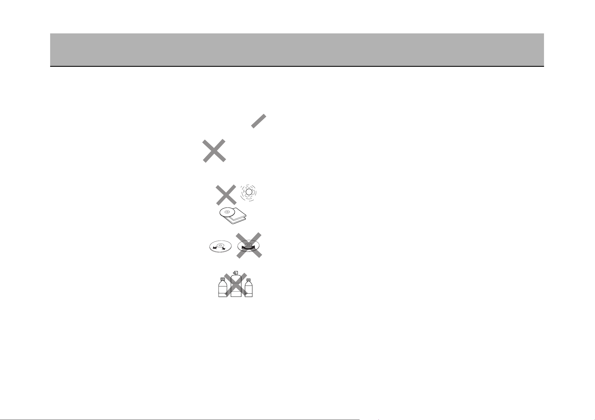
■ About specially shaped discs
Do not use specially formed discs such as heart-shaped or hexagonal discs with this
unit. These may not only damage the unit but, when ejecting the disc, it may fly out and
cause injury due to its high speed rotation.
■ About the included map DVD-ROM
This disc is especially made for the unit. Using in another device may lead to damage to
that device.
■ About copy protected CDs (copy control CD)
The world is divided in 6 regions with corresponding region numbers for DVD software.
This is to enable DVD players to playback only DVD software with corresponding region
numbers. This unit will not playback any DVD video disc whose region number is other
than “1” or “ALL”.
This unit’s region number is “1”.
1
¡Discs whose region number is “ALL” can be played back by DVD players with any
region number regardless of the region.
¡Discs whose region number is not indicated has a region number even though it is
not shown. Contrary to discs that can only be played back using only DVD players
with corresponding region numbers, there is a possibility that discs with no indicated
region number may be played back using any DVD player regardless of the region.
¡This unit will not playback discs recorded with a color TV format other than NTSC
even if the region number is “1” or “ALL”.
Hint
Your JPEG imaging recorded in CD-R discs via a PC can be viewed.
zSee p.158, “Viewing JPEG images”.
DISCS THAT CAN BE PLAYED BACK USING THE UNIT
Use CDs that conform to CD Disc standard such as those with the CD logo
mark printed on its label.
Using a CD with a copy protected function configuration whose purpose was to prevent
computer aided reproduction may not playback normally. This is not due to a
malfunction of the unit but rather to a phenomenon that occurs due to the lack of
conformity of copy protected CDs (copy control CD) to CD standards. Should problems
occur with the playback of copy protected CDs (copy control CD), consult the place of
purchase.
ABOUT REGION NUMBERS
JPEG IMAGING
I
N
T
R
O
D
U
C
T
I
O
N
3433
ABOUT DISCS (2)
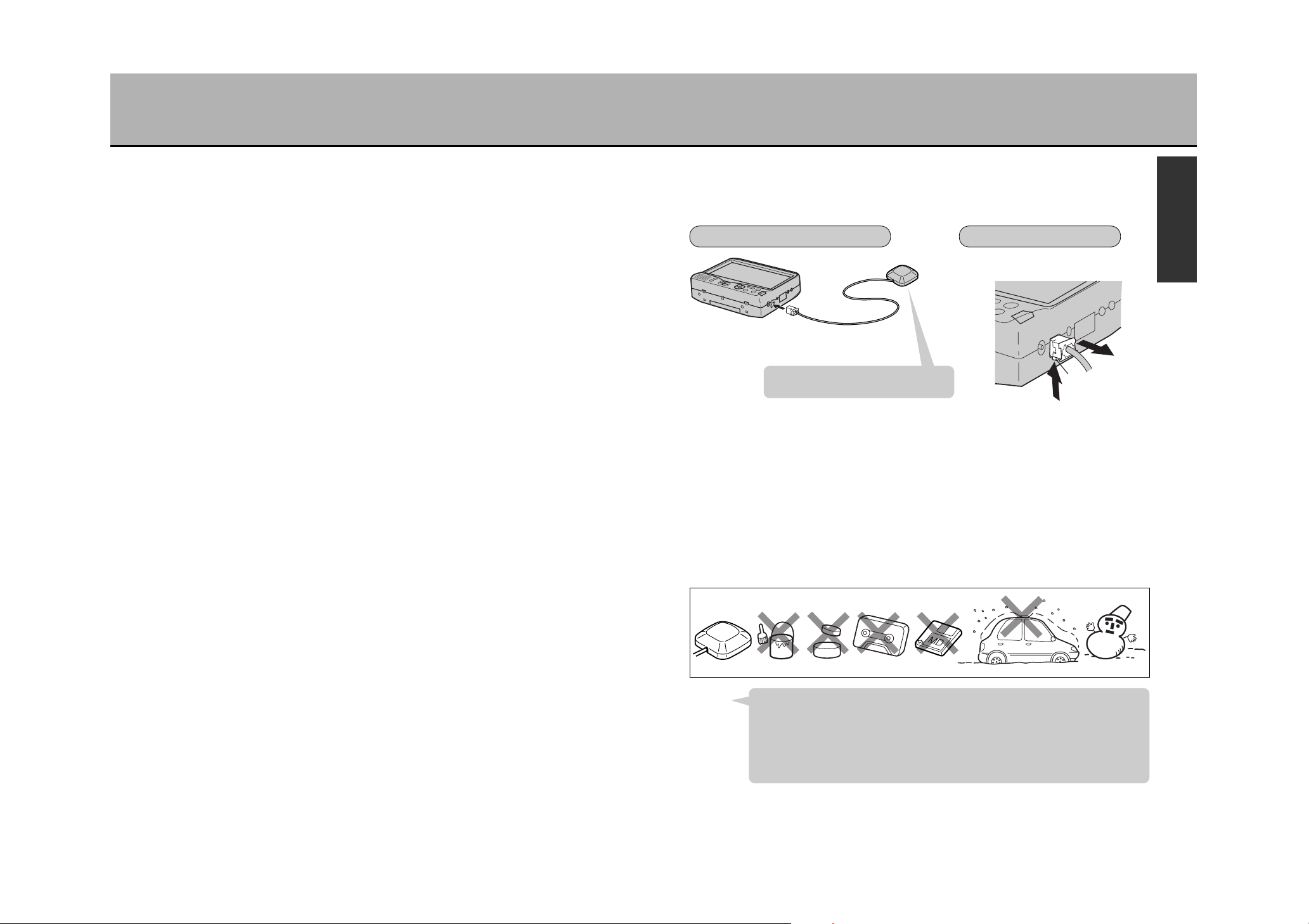
3635
WHAT IS A NAVIGATION SYSTEM (2) ABOUT THE GPS EXTERIOR ANTENNA
¡Refer to the installation manual for how to install the antenna onto your vehicle.
¡After installation, make sure to follow the instructions below:
■ Do not apply paint or auto wax to the GPS exterior antenna. This may lead to reduced
reception sensitivity and a loss of signal reception from the GPS satellite.
■ Do not strike the antenna with an excessively strong spray of water when cleaning your
vehicle. Also, remove the antenna from your vehicle before entering a carwash chamber.
■ The reception sensitivity is diminished by the accumulation of snow on the antenna.
Remove the snow.
■ The GPS exterior antenna is equipped with a powerful magnet. Do not bring magnetic
cards, cassette tapes or watches in close proximity to the antenna. (This may damage
the antenna and render it useless.)
■ About present location errors
The mark denoting your vehicle’s present location and heading may not be displayed
accurately under the conditions mentioned below. The unit is not damaged. Continue
driving (about 30 minutes at 20 mph) and the display will return to normal.
¡Running in reverse
¡Under a continuous elevation
¡In a tunnel exceeding 1 mile in length
¡When meandering in curves
¡When the vehicle’s speed changes abruptly (after exiting a toll booth and accelerating
towards a tunnel)
¡On a loop bridge
¡When using the unit for the first time
¡After debarking a ferry
¡After driving with the DVD screen
¡After driving with the VIDEO screen
¡During tire replacement
¡During tire chain installation
¡When taking the unit into a different vehicle
¡When crisscrossing through a parking lot (especially in an underground or multi-
storied parking structure)
After having purchased the unit, mount
the GPS exterior antenna outside.
Press the protrusion and remove.
¡The GPS exterior antenna must be connected in order to use the unit as a navigator.
(The unit cannot use other types of antennas.)
Not doing so will render present geographic location determination impossible.
INSTALLATION METHOD REMOVAL METHOD
To the GPS exterior
antenna terminal
Tab
After having purchased the unit, the unit will display the present location as in the San
Francisco area. Signals from the GPS satellite cannot be received from inside a
building. If the present display does not change from the San Francisco area map,
this means that the unit is not receiving any signals from the GPS satellite. Take the
antenna out to a location where signals are not obstructed and proceed with
reception.
zSee p.183, “Receiving signals from the GPS satellite”.
Hint
Paint
Wax
Cassette tape
I
N
T
R
O
D
U
C
T
I
O
N
37 38
COMPONENT NAMES AND FUNCTIONS (1)
4039
COMPONENT NAMES AND FUNCTIONS (2)
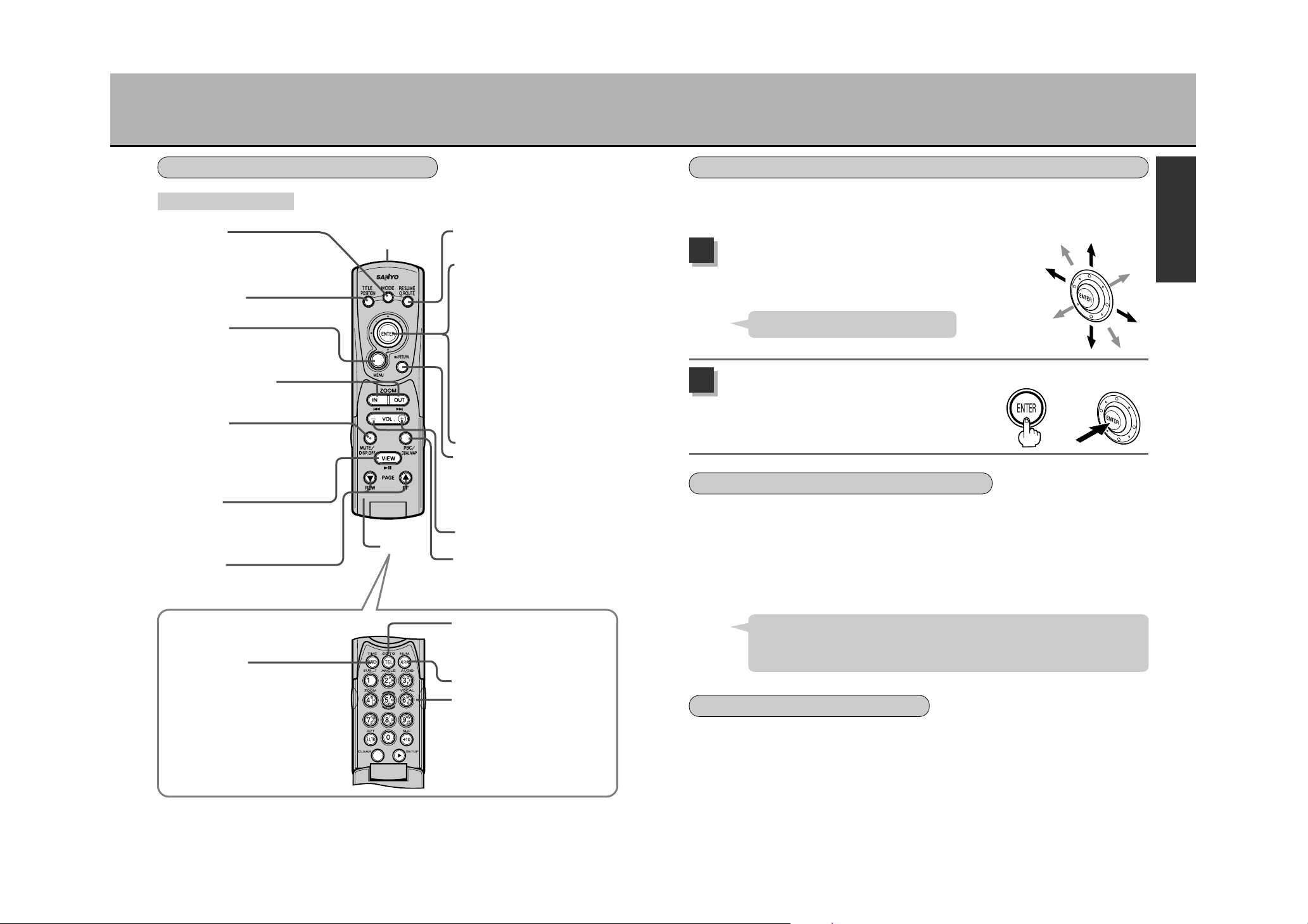
Übutton
The screen will switch from the NAVI mode
to the DVD mode to the VIDEO mode (only
with a video deck/video camera connected)
every time this button is pressed. (See p.56)
Ç
button
Used for a quick route search.
(See p.66 and 67)
10-key and editing button
Used when inputting alphanumerically.
Remote control
infrared transmitter
Flip-top
Ébutton
¡Displays the menu screen.
¡Pressing for over 1.5 seconds will switch to
the image adjustment mode. (See p.178)
à
button / âbutton
IN/OUT buttons Enlarge (IN) Reduce (OUT)
(See p.60)
Q
button
¡This cuts the sound output. Press again to
return the sound. (See p.40)
¡Press over 2 seconds to erase the screen.
Press again for over 2 seconds to
redisplay the screen. (See p.40)
è
button
¡Pressing this button when the telephone
number input screen is displayed will
show the map that corresponds with the
inputted number.
¡Pressing when the ABC input screen is
displayed will start a search for the
inputted point of interest or geographic
name.
Joystick (u)
¡Used when changing the position
display map and when selecting items
appearing on the screen. (See p.40)
¡When in image adjustment mode, use
the vertical Joystick (d) to select
items to adjust and the lateral Joystick
(s) to perform the adjustment. (See
p.178 to 180)
Ä
button
¡This button executes the item selected
on the screen. (See p.40)
¡Press while the screen is displaying a
map and a quick menu will appear.
(See p.70)
Å
button
¡Press this button to move the display
back one screen when using the menu.
(See p.40)
¡
Pressing while in image adjustment
mode will cancel that mode. (See p.180)
Öbutton
– : reduce volume, + : increase volume
á
button
Every time this button is pressed, the map
display switches from 3D view to planimetric
map (North Up) to planimetric map (Heading
Up). (See p.59)
ã
button
Press for the next/previous page when the
display is incomplete on only one screen.
ê
button
Ebutton
This button displays the telephone
number input screen when searching
for a destination by telephone number.
é
button
Every time this button is pressed, the
screen toggles between double screen
display and full screen display. (See p.115)
Ñbutton
Displays the present location map. (See p.62)
Flip-top opened
Select a menu (item) on the screen.
Use the joystick to select.
The joystick can be moved in 8 different
directions.
1
Press (execute) the selected menu (item).
Press the Ä button.
The unit executes the item selected and displays
the next screen.
2
To use this unit, selecting and pressing (executing) the menus (items) appearing on
the screen is the most basic operation. This operation is performed using the cursor
key and the Ä button. Learn how to use them well for smooth operation.
REMOTE CONTROL
OPERATING THE NAVIGATION UNIT
HOW TO USE THE JOYSTICK AND THE Ä BUTTON
* The illustration
on the right
represents the
remote control.
Use the joystick also to move the map.
Hint
MAIN UNIT
REMOTE
CONTROL
HOW TO USE THE Å BUTTON
The Å button has two functions.
¡Returns the display to the previous screen. (Cancel)
Pressing when effectuating settings will cancel the settings and return the display to the
previous screen.
¡Ends settings
Pressing after having completed setting the unit will update the settings and return the
display to the map screen.
Within the operation procedures described in this manual, instances when the
Å button is to be pressed (such as after completing the settings) are clearly
indicated. At other times, pressing this button will advance the display to the previous
screen.
Hint
ABOUT THE Q BUTTON
¡Pressing the Q button will display “MUTE” and temporarily cut off the
sound. Pressing once more will erase the “MUTE” display and return the sound.
¡Pressing Q for over 2 seconds will indicate “DISPLAY OFF” for roughly 3
seconds and blacken out the image on the screen. Pressing once more for over 2
seconds will return the image on the screen.
I
N
T
R
O
D
U
C
T
I
O
N

4241
4443
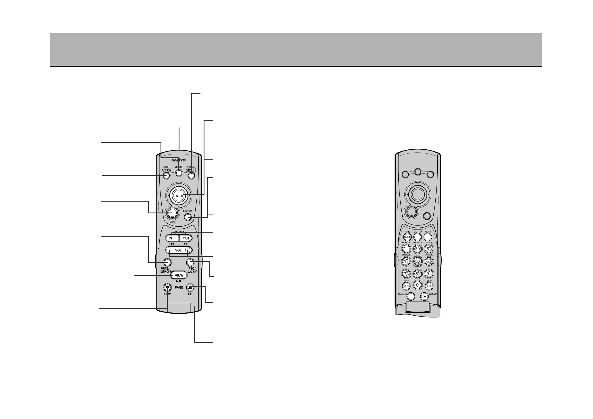
infrared transmitter
Übutton
Every time this button is pressed, the screen
switches from the NAVI to the DVD to the
VIDEO mode. (See p.141)
button
L
Pressing this button while a DVD disc is
being played back will change the screen
into the title menu. (See p.145)
Ébutton
¡Pressing while the DVD disc is playing
back will move the display to the menu
screen. (See p.146)
¡Pressing for over 1.5 seconds will switch to
the image adjustment mode. (See p.178)
Qbutton
¡This cuts the sound output. Press again
to return the sound. (See p.144)
¡Press over 2 seconds to erase the
screen. Press again for over 2 seconds
to redisplay the screen. (See p.144)
PLAY/PAUSE button (q)
¡Press to start playback. (See p.143)
¡Pressing while playing back will pause the
image and sound. Press again to resume
playback. (See p.143)
button
‰
¡Rewinds the image at certain speeds.
(See p.144)
¡Pressing while the image is paused will rewind
slowly (when in DVD video mode only).
(See p.144)
Remote control
®
After having displayed the menu screen while
the DVD disc is playing back, press this
button to resume playback starting at the
place before the menu screen was displayed.
button
JOYSTICK (a)
¡Used to select items on the screen.
¡When in image adjustment mode,
use the vertical joystick (d) to
select items to adjust and the lateral
joystick (s) to perform the
adjustment. (See p.178 to 180)
Ä
¡This button executes the item
Å
¡This button returns the display to
¡Pressing while in image adjustment
button
selected on the screen.
button
the previous selection screen when
effectuating initial settings.
mode will cancel that mode.
(See p.180)
STOP button (w)
Pressing while playing back will stop
playback. (See p.143)
SKIP button (r/e)
Used for chapter/track/image
back/image forward while the disc is
played back. (See p.144)
button
Ö
– : reduce volume,
+ : increase volume
π
button
For JPEG imaging, select the
slideshow display format.
(See p.161)
button
F
¡Fast-forwards the image at certain
speeds. (See p.144)
¡Pressing while the image is paused
will fast-forward slowly (when in
DVD video mode only).
(See p.144)
Flip-top

4645
CHARACTER INPUT USING THE 10-KEY ON THE REMOTE CONTROL
Alphanumeric input can be entered
directly by using the 10-key, by selecting
characters from the keyboard displayed
on the screen using the joystick or by
mixing both methods.
Multiple alphanumeric characters are
allocated for every button on the 10-key.
The following describes each button and
explains the function of the edit button.
Button Input characters
button
button
button
button
button
button
button
button
Numeral : 1
Alphabet : ABC
Numeral : 2
Alphabet : DEF
Numeral : 3
Alphabet : GHI
Numeral : 4
Alphabet : JKL
Numeral : 5
Alphabet : MNO
Numeral : 6
Alphabet : PQRS
Numeral : 7
Alphabet : TUV
Numeral : 8
Alphabet : WXYZ
Numeral : 9
Numeral : 0
Erases one character
at a time.
Moves the cursor 1
character at a time to
the right.
* When using the same
button to input another
character, press the
button after the
first character is
inputted and the cursor
will move to the right.
Then, input the next
character. When using
a different button to
input the next
character, the cursor
will automatically move
to the right.
button
button
CLEAR button
button
w
q
e
Repeatedly press the button
on which the character to be
inputted is located and it will
be displayed on the screen.
1
Press the button to confirm
the character selection.
* If the character desired is not allocated
on the same button, it is not necessary
to press the button. Pressing the
next desired button will automatically
confirm the previous character
selection.
2
* When having made an error inputting
characters, press the ç button and
reenter the character.
Repeat steps and to
input characters.
3
Only numbers can be inputted.
Press the button for the
number desired.
* The character is confirmed the
moment it is inputted.
* Press the ç button when
having made an error and reenter the
number.
1
Press the è button
to initiate a map search.
* When there is no data available, “No
data found” is displayed.
2
CHARACTER ALLOCATION
q
w
e
Character allocation list
HOW TO ENTER CHARACTERS
USING THE 10-KEY
Ex.) Inputting “AB”
Inputting “AD”
AB
AD
INPUTTING NUMBERS IN THE
TELEPHONE NUMBER INPUT SCREEN
¡The input method described
here is but one example.
There are other character
input screens.
Refer to the pages describing
each screen for their
respective input methods.
¡When inputting using the 10-
key, you can also move the
cursor to the desired character
on the keyboard displayed on
the screen and input
characters mixing both
methods.
Hint
1 2
I
N
T
R
O
D
U
C
T
I
O
N
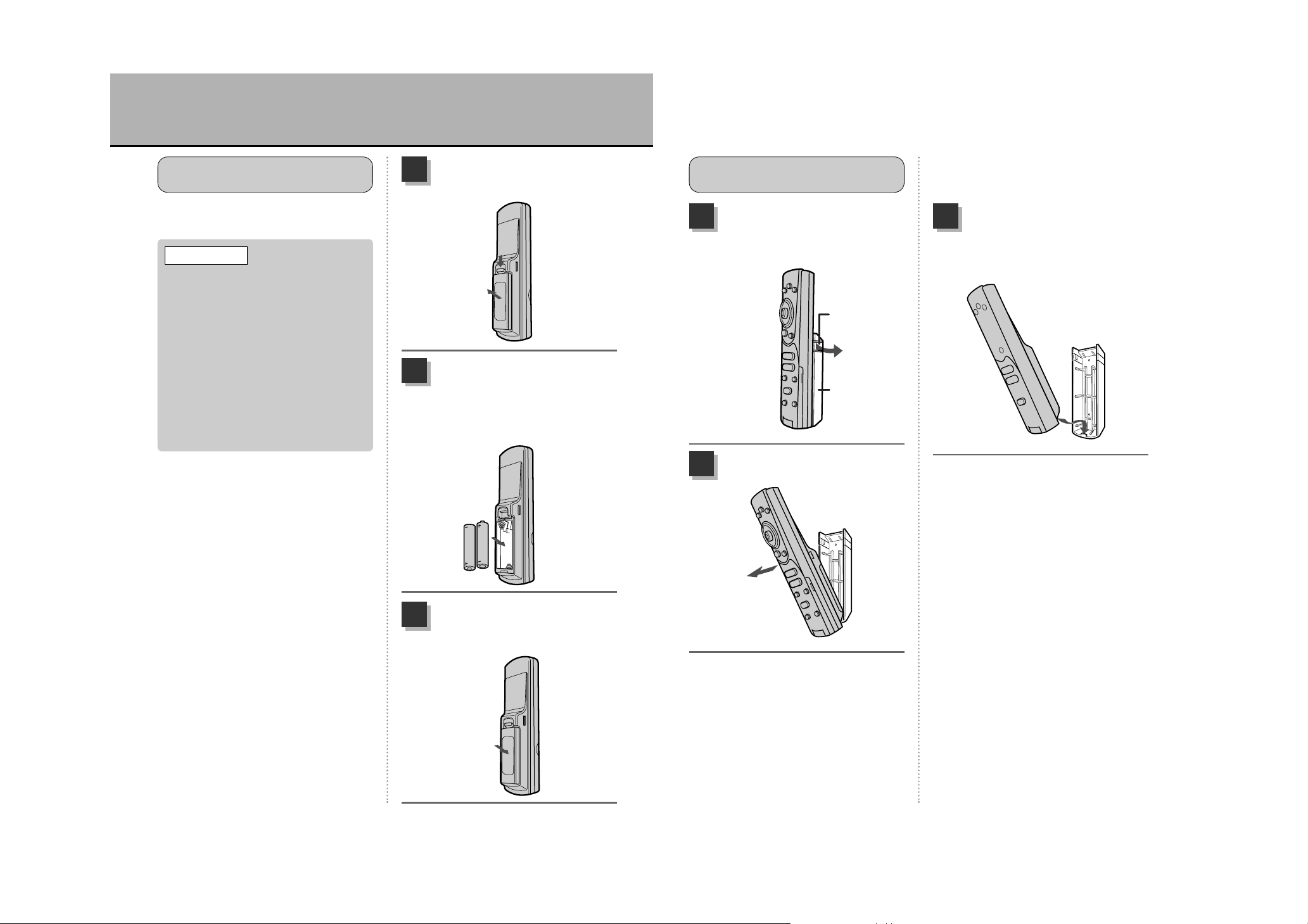
HOW TO HANDLE THE REMOTE CONTROL (1)
¡Align the “+” and “–” terminals
correctly and do not mix an old with a
new battery or two different kinds of
batteries. Otherwise, the batteries may
leak and crack leading to fires and
injury.
¡Batteries cannot be recharged.
¡Installing or leaving the remote control
in direct sunlight such as the
dashboard will cause deformation and
malfunctions. Exercise caution.
¡Spilling water, beverages or solvents
onto the remote control may cause
damage. Exercise caution.
Press down on the tab and
pull the cover outward.
1
The battery inserted on the
left has its minus terminal
pointing upwards and the
right battery has its plus
terminal pointing upwards.
2
Align the bottom tab of the
cover with the groove on the
remote control and close.
3
The remote control uses two AAA
batteries.
INSERT BATTERIES IN THE
REMOTE CONTROL
t CAUTION
Push the side tabs on the
holder a bit outwards and
remove.
1
Pull it outwards.
2
REMOVE THE REMOTE
CONTROL FROM THE HOLDER
Align the tab on the bottom
of the holder with the groove
on the bottom part of the
remote control.
1
< When removing the remote control
from the holder,
pull the top of the remote control upwards.
< When returning the remote control
device to the holder,
refer to
“ ”
on the previous page.
HOW TO HANDLE THE REMOTE CONTROL (2)
RETURNING THE REMOTE CONTROL TO THE HOLDER
Mounting
example
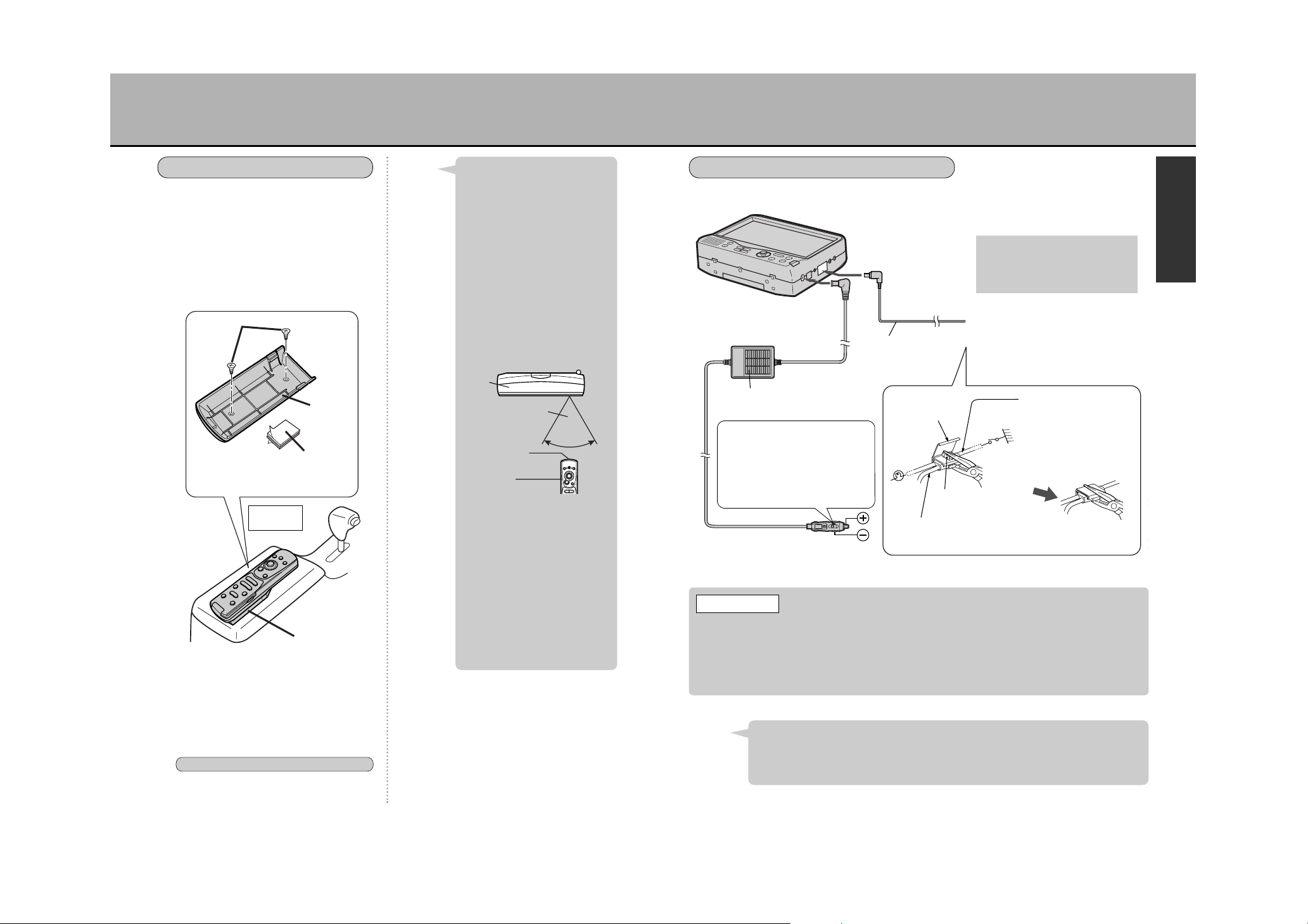
ABOUT THE POWER SOURCE (1)
Use the 12V cigarette lighter connector cable and parking brake
connector cable included with the unit.
* If necessary, use the included cord clip to affix the cord.
If mounting the holder in your vehicle,
affix using the included tapping screws
(M3 x 8) or the magic tape.
* When mounting using the magic tape, clean the
adhesion surface as much as possible.
* When mounting using the tapping screws, holes
must be made in the mounting surface. Exercise
caution.
MOUNTING THE HOLDER
Velcro tape
* Affix using tapping screws or
Velcro tape.
Holder
Holder
Tapping
screw
(M3 x 8)
To operate the unit using the
remote control, point the
remote control infrared
transmitter towards the unit’s
remote control infrared
receiver. To use the remote
control as is from the mounted
holder, follow the instruction
below:
¡Mount the holder in a way so
that the remote control infrared
transmitter is oriented toward
the unit’s remote control
infrared receiver.
Hint
¡After confirming proper remote
control operation from the
mounting area, affix using the
included tapping screws (M3 x
8) or the Velcro tape.
¡Under direct sunlight, the unit
may not properly receive the
signals transmitted by the
remote control. In such a case,
bring the remote control in
close proximity to the unit’s
infrared receiver and operate.
Remote control signal range
Within 60° laterally
from the infrared
receiver
60°
Infrared
transmitter
Remote
control
Main
unit
When connecting the unit to the cigarette lighter, the vehicle battery will be drained of its
power as long as the lighter’s power supply is turned ON. If your vehicle’s cigarette lighter
power supply does not cut off when turning OFF the engine, make sure to pull the 12V
cigarette lighter connector cable from the vehicle’s cigarette lighter socket when turning
OFF the engine. Leaving the connector in the socket for extended periods may drain the
battery.
t CAUTION
¡For safety, videos or DVDs cannot be watched nor can selections be made on the
menu if the parking brake is not set.
¡If turning ON the engine while using the navigation system, the unit may return to
the initial screen due to a drop in voltage.
Hint
USING A 12V VEHICLE BATTERY
Connect to the DC
input 9V terminal
Connect to the
brake terminal
Parking brake
connector cable
* The parking brake signal line
position varies depending on the
vehicle model. Ask your auto
dealer for details.
Connect to the vehicle’s parking brake
signal line (grounded when the parking
brake is pulled)
* Use the included self-lock connector.
12V cigarette lighter
connector cable
Connect to the 12V
cigarette lighter socket
Self-lock
connector
Parking
brake
lamp
Parking brake
switch
Push in the metal part
to anchor the 2 wires.
Parking brake connector cable
Insert the end into the self-lock
connector.
Auto parking brake signal
line
Insert from the cut end of the
self-lock connector
Close the self-lock
connector securely.
Slide switch:
The slide switch is set on the N side
at our factory. The cable can be used
on the N side for most vehicle
models, however, for European
models and other vehicles with large
socket diameters, the slide switch
should be switched to the W side.
49 50
I
N
T
R
O
D
U
C
T
I
O
N
5251
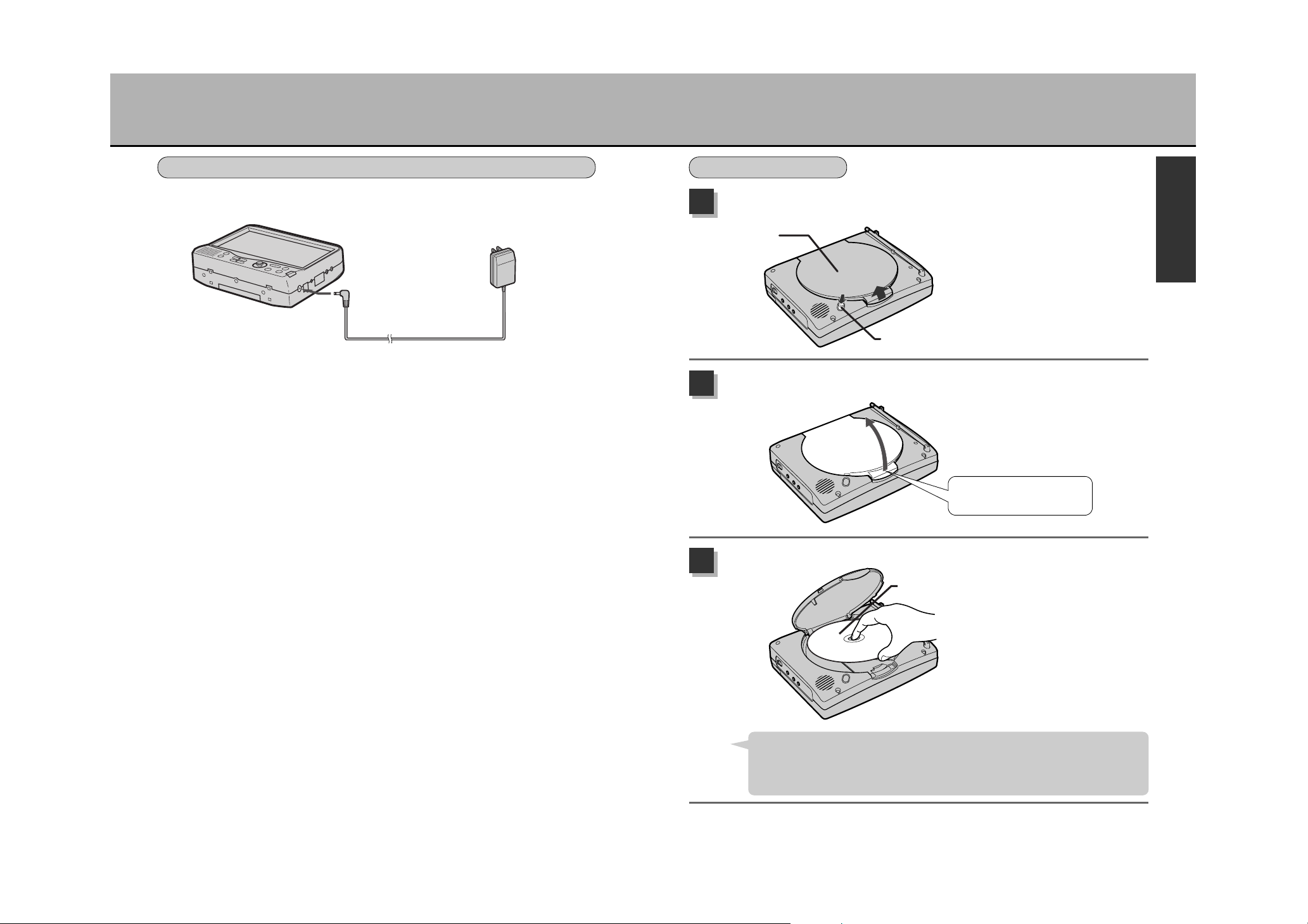
ABOUT THE POWER SOURCE (2) INSERTING/REMOVING A DISC (1)
Press the button for opening the cover.
1
Open the disc insert aperture cover.
2
Insert a disc.
3
The disc insert aperture
cover opens slightly.
Align the disc’s central
opening with the black
holder in the housing and
insert the disc with the
printed surface facing
upwards.
USING A HOUSEHOLD POWER SOURCE (AC 120V, 60Hz)
Use the AC/DC adaptor included with the unit.
Connect to the household power source
(AC 120V, 60Hz)
AC/DC adaptor
Connect to the DC
input 9V terminal
INSERTING A DISC
Disc insert
aperture cover
Button for opening the cover
Place your finger here and
lift the disc cover.
Printed surface
¡When playing back, the disc rotates at a high speed. Make sure to insert the disc
and press down until a snap is heard to ensure that the disc will not fly off during
playback.
¡Insert 3inch(8cm) CDs in the same manner. (Adaptor not required)
Hint
I
N
T
R
O
D
U
C
T
I
O
N
53
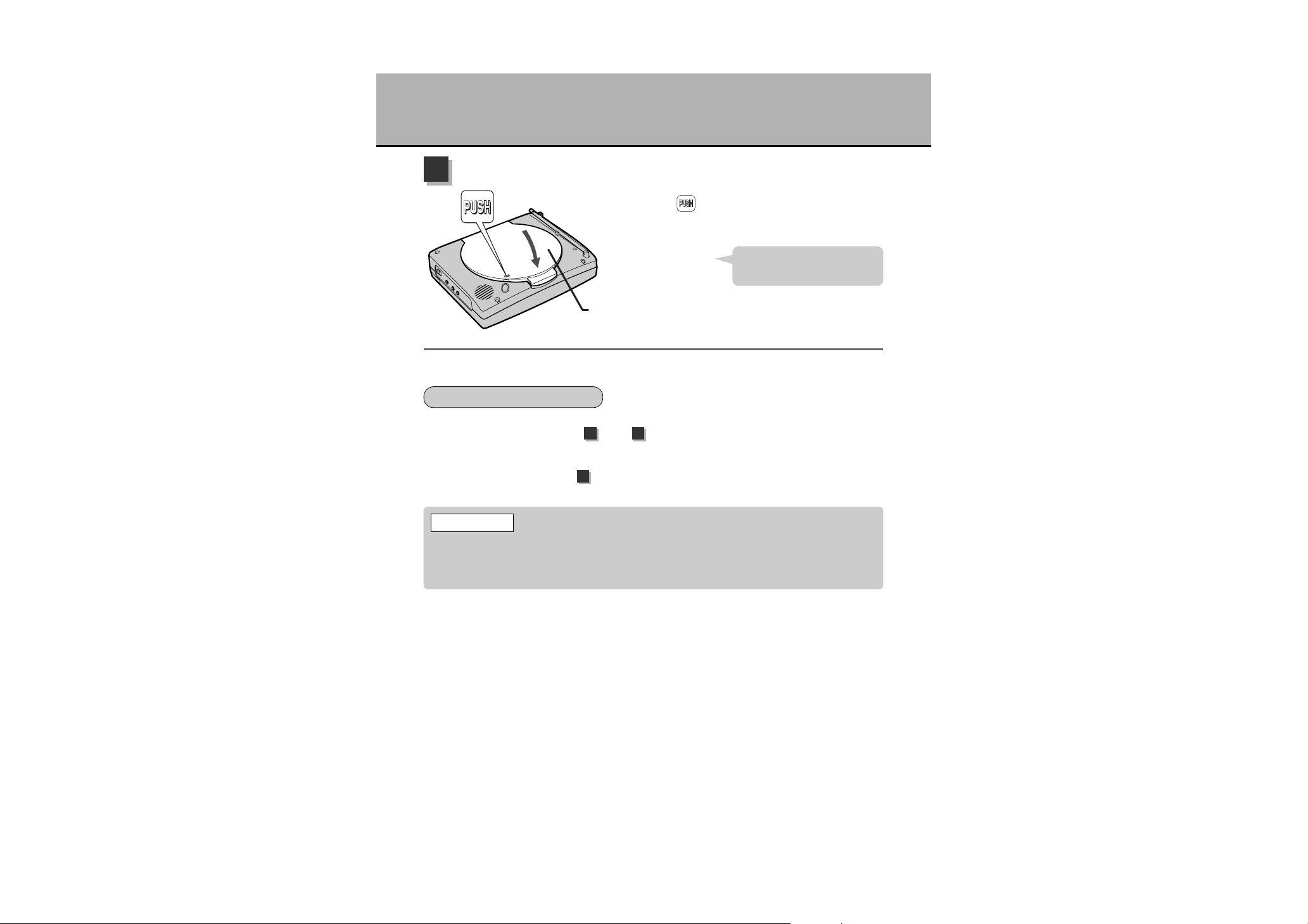
INSERTING/REMOVING A DISC (2)
Close the disc insert aperture cover.
4
1
As described in steps and (p.52), open the disc cover, wait till
the disc stops rotating and pull the disc out from its edge.
2
As described in step above, close the disc cover.
Press the “ ” mark appearing on the cover and
close the cover completely.
The disc will not playback if the
cover is not completely closed.
Hint
Disc insert
aperture cover
REMOVING THE DISC
During playback, if cutting the power OFF or switching to VIDEO mode before opening the
disc cover, it may take a moment before the disc stops rotating. Make sure to remove the
disc only after it stops rotating. Not doing so may result in scratches on the disc or cuts on
your fingers.
t CAUTION
1 2
4

54
N
A
V
I
NAVI OPERATION
DISPLAYING THE MAP SCREEN ...................................................................55
HOW TO VIEW THE MAP SCREEN .................................................................57
CHANGING THE MAP DISPLAY ......................................................................59
QUICK ROUTE SEARCH ..................................................................................66
BASIC MENU OPERATIONS ............................................................................68
LIST OF MENU ITEMS......................................................................................69
ABOUT THE QUICK MENU ..............................................................................70
SEARCHING FOR A GEOGRAPHICAL POINT................................................71
POINTS OF INTEREST CATEGORIES ............................................................82
REGISTERING YOUR HOME ...........................................................................84
ABOUT SETTING ROUTES .............................................................................85
SINGLE-ROUTE/MULTI-ROUTE SEARCH ......................................................89
MODIFYING A ROUTE......................................................................................96
DISPLAYING THE PRESENT ROUTE..............................................................99
STORING/DELETING THE PRESENT ROUTE..............................................100
VIEWING ROAD INFORMATION WITH THE PRESENT ROUTE..................102
SEARCHING FOR A WAY HOME...................................................................103
STOPPING/STARTING ROUTE GUIDANCE..................................................104
MODIFYING ROUTE CONDITIONS ...............................................................105
STRAYING OFF THE ROUTE (REROUTE)....................................................107
THE ROAD AHEAD CANNOT BE TAKEN (DETOUR SEARCH) ...................108
SAVED ROUTES LIST ....................................................................................109
ROUTE SIMULATION .....................................................................................112
CHANGING THE MAIN SCREEN SETTINGS ................................................113
SETTING THE 2-SCREEN DISPLAY..............................................................115
CHANGING THE ROUTE GUIDANCE SCREEN SETTINGS.........................118
INDICATING THE STREET NAME .................................................................122
CHANGING THE UNIT OF DISTANCE, THE COLOR OF
THE MAP AND THE PRESENT LOCATION MARK .......................................123
DISABLING THE REGISTERED POINT MARK DISPLAY..............................124
DISPLAYING LATITUDINAL AND LONGITUDINAL COORDINATES............125
CLOCK SETTING ............................................................................................126
USING TRACKS ..............................................................................................127
MODIFYING THE PRESENT LOCATION MARK LOCATION
AND BEARING ................................................................................................131
EDITING/VIEWING REGISTERED POINTS ...................................................133
RETRIEVING REGISTERED POINT MAPS ...................................................136
DELETING REGISTERED POINTS ................................................................137
VIEWING GPS INFORMATION.......................................................................138
VERIFYING UNIT CONNECTION ...................................................................139


58
N
A
V
I
57
3D icon
Indicator denoting your vehicle
3D icon
Indicates specified buildings three-dimensionally.
Indicator denoting your vehicle
This shows the position of your vehicle (present location) and the heading.
1
2
1
2
Map reduction
1/3125
1/6250
1/12500
1/25000
1/50000
1/100000
1/200000
1/400000
1/800000
1/3200000
1/12800000
1/51200000
Scale
1/64 mile
1/32 mile
1/16 mile
1/8 mile
1/4 mile
1/2 mile
1 mile
2 mile
4 mile
16 mile
64 mile
256 mile
Scale
25 m
50 m
100 m
200 m
400 m
800 m
2 km
4 km
8 km
32 km
128 km
512 km
MAP REDUCTION SCALE LEVELS
VIEW
Recommended
route indicator
PLANIMETRIC MAP SCREEN
Road
Reduction scale
Indicator
denoting your
vehicle
Simple turning
mark
Bearing indicator
Bearing indicator
The “N” orientation denotes the north.
Simple turning mark
Simply indicates right or left turns.
Recommended route indicator
When the unit searches for a route, the
recommended route is indicated as a
thick purple or green line (as per setting,
zsee p.120, “Select the set route
color”). Toll roads are shown in red.
Estimated time to
destination and distance
remaining
When effectuating route guidance, the
estimated time to destination and the
distance remaining are indicated.
Indicator denoting your
vehicle
This shows the position of your vehicle
(present location) and the heading.
Reduction scale
This shows the map scale.
Road
Road types are classified by color.
Red: highways, freeways, toll roads
Orange: main regional roads
Gray: other local roads
8
7
6
2
3
1
2
3
4
6
7
8
HOW TO VIEW THE MAP SCREEN
GPS reception display
1
5
4
The navigation system displays various types of information on the map screen.
THE FOLLOWING IS A TYPICAL EXAMPLE OF A MAP DISPLAY
GPS reception display
Indicates a color denoting the positioning
accuracy for the present location.
Yellow: The present location is
determined.
Gray: The present location is not
determined or is in the process of
being determined.
Proper positioning may take a
moment before being effectuated.
For about 3 to 4 minutes after
introducing the power supply, the
GPS reception display will be
indicated in gray.
Hint
Estimated time to
destination and
distance remaining
5

60
N
A
V
I
59
Most detailed level for the
planimetric map screen.
Press the
à button.
Press the
â button.
Broadest level for the planimetric
map screen.
Heading Up
North Up
When in planimetric map screen
The map’s display direction can be changed.
zSee p.116, “Select the map display method”.
See p.113, “Changing the main screen
settings”.
¡Heading Up
With the heading always towards the top
of the screen, the mark indicating your
vehicle and the screen’s orientation can
be coordinated. The map rotates along
with the veering of the vehicle.
¡North Up
If a moving map is confusing, set the
screen to show the northern direction as
the top.
CHANGING THE MAP DIRECTION
¡When enlarging the map (detailed
map)
Press the à button.
* A detailed map showing a 1-level
enlargement of the present map is displayed.
¡When reducing the map (broad map)
Press the â button.
* A broad map showing a 1-level reduction of
the present map is displayed.
¡When free-zooming the map
Press down on the à (map
enlargement) or â (map reduction)
button continuously.
* The map reduction scale level presently
displayed changes 1 level at a time. Lifting
your finger will stop at that reduction scale
level. Lift your finger when the desired
reduction level appears.
ENLARGEMENT/REDUCTION
OF THE MAP
CHANGING THE MAP DISPLAY (1)
Planimetric screen
This map screen appears as if looking
directly down from above.
3D View
Map screen showing a view looking
down and forward from above.
Planimetric map screen showing
an urban area
3D View of an urban area
Press the à button.
Press the à button.
3D View Planimetric screen
(North Up)
Planimetric screen
(Heading Up)
There are 3 types of map screens available:
planimetric map screen (North Up),
planimetric map screen (Heading Up) and
3D View. Press the ä button to switch
screens. Every time the ä button is
pressed,
SWITCHING MAPS
…are inter-switched.
About the planimetric map
screen
¡A “¡” mark indicates your
vehicle at full stop.
About 3D View
¡When in 3D View, the map
scroll may be a bit slow.
¡The heading direction is always
towards the top of the screen.
¡Street and area name displays
appearing in the foreground
and background of the screen
may differ.
¡In order to keep the screen
display from becoming too
cluttered, character spacing is
thinned out depending on the
screen being viewed. The
character display may vary
when the screen is changed
and the same character may
not be displayed. Similarly,
multiple display of street names
may also occur.
Hint

61 62
N
A
V
I
CHANGING THE MAP DISPLAY (2)
This example represents
pressing the top right direction.
aa
Using to scroll the map
Moving the cursor in 8 directions on the
map screen enables the map to be scrolled.
Pressing a given key continuously will scroll
the map in that direction.
Using to select and execute items on the screen menu
Moving the cursor in 4 directions on the screen showing the menu enables menu item
selection. The menu item selected will appear in yellow. Pressing once will move the item
indication (in yellow) once over to the next item. Selecting an item and pressing the
Ä button will execute that function or go to the next menu.
* The illustration
shows the remote
control device.
When moving the map screen, move the Joystick.
* Pressing down the Joystick to the desired direction will scroll the map in that direction.
MOVING THE MAP
(scroll)
¡The Joystick can move in 8
directions (u).
¡To return to the present location,
press the Ñ or the
Å button.
Hint
HOW TO USE THE CURSOR
¡Pressing repeatedly on the
à/â button enables
the unwanted reduction scale
level screen displays to be
skipped.
¡See p.58, “Map reduction
scale levels”, for details
pertaining to planimetric map
screen and 3D View reduction
scale levels.
Hint

64
N
A
V
I
63
Select and press the Ä
button and button. The following
message will appear on the screen.
YES
Save Place
When searching for a route, the following
displays appear as per the conditions.
* zSee p.85, “About setting routes”, for
route searching methods.
About geographic point
registration
Scroll the map and press the Ä
button to display the next screen.
ABOUT DISPLAYS DURING
ROUTE SEARCH
Registering the name
Select the item
(Name/TEL/Memo/Mark) to
register and press the
Ä button.
1
Name input screen
Name

66
N
A
V
I
65
QUICK ROUTE SEARCH (1)
Align the destination with the cursor and press the quick route button to initiate a
search for a reference route from your present location to the destination based on the
map disc data and the search conditions (Faster Route/Shorter Route/Optimal,
zsee p.105 “Modifying route conditions”). Also, if having registered the location of
your home, the unit will search for the way home from your present location.
Present location display screen (example)
If this mark is yellow,
the positioning is O.K.!
Press the Ñ button
to confirm the present location
positioning.
1
Use the Joystick to scroll the
map and display the map of
the destination.
zSee p.62, “Moving the map”.
See p.60, “Enlargement/reduction
of the map”.
2
3
Choosing the most detailed map
reduces the positioning error!
Cursor
Select and press the
Ä button.
This initiates a reference route search.
When the search is complete, wait a
moment until the route guidance screen
appears.
YES
4
When pressing the button
and a confirmation message appears
to set highways, select to
register highways or to register
local roads and press the Ä
button.
NO
YES
Q.ROUTE
Align the cursor on the
destination and press the
Ç button.
SEARCHING FOR A ROUTE
FROM YOUR PRESENT LOCATION
TO THE DESTINATION
You can interrupt
searches by pressing the
É button.
Inputting.
2
q Select and press the
Ä button.
< You can also delete characters by
opening the remote control fliptop and pressing the ç
button.
Delete
When inputting is complete,
select on the item
board and press the Ä
button. The inputted content
is confirmed.
To change/register another item
(Name/TEL/Memo/Mark), repeat steps
to .
Done
3
To complete setting…
Press the
on the
screen to return to the map you
stored now.
Press the Ñ button to
return the screen to the present
location map.
Press the É button to
return to the menu screen.
Display Map
4
Clearing the inputted (A) character.
Example
Inputting “A” / “B” in the memo.
w Inputting “B”
1 3
CHANGING THE MAP DISPLAY (4)

68
N
A
V
I
67
Example
Viewing the GPS Information screen
Press the É button.
1
Most of the operations for the navigation system are effectuated using the menu.
It is an important tool to ensure the proper operation of the unit. Become well
accustomed to the menu.
Select from the drop-down menu and press the
Ä button.
GPS Information
2
When finished viewing…
< When selecting , press the Ä button or the Å
button on the remote control.
The display returns to the menu screen.
< Press the Ñ button.
The display returns to the present location map.
< Press the É button.
This display returns to the menu screen.
BACK
3
BASIC MENU OPERATIONS
Present location display screen (example)
Press the Ñ button
to confirm the present location
positioning.
1
Press the Ç button
on the present location display.
2
Select and press the
Ä button.
This initiates a reference route search.
When the search is complete, wait a
moment until the route guidance screen
appears.
You can interrupt searches by pressing
the É button.
YES
3
SEARCHING FOR A ROUTE
FROM THE PRESENT
LOCATION TO YOUR HOME
If this mark is yellow,
the positioning is O.K.!
¡To search for a route home, it
is necessary to register the
location of your home in
advance.
zSee p.70.“About the quick
menu”.
zSee p.84.“Registering
your home”.
¡When initiating a new route
search, the previously
searched reference route is
deleted. To save the reference
route in the memory, refer to
“Storing the present route”.
¡Reference routes vary
depending on the map disc.
It may not always select the
shortest route for you.
Hint
Depending on changes in traffic
conditions, you may not be able to drive
on the reference route provided by the
unit. In such a case, proceed following
the actual traffic conditions.
t CAUTION
QUICK ROUTE SEARCH (2)

70
N
A
V
I
69
ABOUT THE QUICK MENU
A quick menu is set in this unit to facilitate its main operations. When viewing a map
display and pressing the Ä button, the quick menu appears. Select an item
using the vertical joystick (d) and press the Ä button.
q
w
Quick menu
Quick menu
Geographical point registering effectuated.
“About geographic point registration” (zSee p.63 to 65)
Geographical point registered as the location of your home.
“Registering your home” (zSee p.84)
Select either “Night Mode”, “Auto Change” or “Day Mode”.
zSee p.123, “Select the map color (Day/Night/Auto)”
Select “Stopping / Starting Route Guidance ” (zSee p.104)
* No display is provided if the present route does not exist in the
map disc.
Geographical point registering effectuated.
“About geographic point registration” (zSee p.63 to 65)
Geographical point registered as the location of your home.
“Registering your home” (zSee p.84)
Select either “Night Mode”, “Auto Change” or “Day Mode”.
zSee p.123, “Select the map color (Day/Night/Auto)”
WHEN HAVING PRESSED THE
Ä
BUTTON
WHEN IN PRESENT LOCATION DISPLAY
WHEN HAVING PRESSED THE
Ä
BUTTON
WHILE MAP SCROLLING
LIST OF MENU ITEMS
Menu
Menu Menu
Drop-down menu
Menu
Drop-down menu
Drop-down menuDrop-down menu

SEARCHING FOR A GEOGRAPHICAL POINT (1)
Press the É button.
1
Select from the
drop-down menu and press
the Ä button.
Region
2
Select or
and press the Ä
button to choose the region.
BackwardForward
3
Select and press the
Ä button.
Select
4
Select from the dropdown menu and press the Ä
button.
Address
Select and
press the Ä button.
City Name Input
1
Input the city name.
* When inputting the first few
characters, a corresponding list will
appear.
2
• When inputting a city name
Select a corresponding item
from the list and press the
Ä button.
3
Input the house number,
select and press the
Ä button.
Search
4
Input the street name, select
an item from the
corresponding list and press
the Ä button.
: A map of the surrounding area will
be displayed.
5
For returning to the present
location, press the
Ñ button.
6
N
A
V
I
71 72
SELECT THE REGION
Region
¡The Region can also be
selected by the or
items in
the drop-down menu.
Point of Interest
Address
Hint
SEARCHING FOR A GEOGRAPHICAL
POINT BY THE ADDRESS
Address
* If the house number is not known,
select and
press the Ä button.
House No. Unknown
Select and
press the Ä button.
City Unknown
1
Input the house number and
press the è button.
2
• If the city name is unknown
Input the street name and
press the Ä button.
* When inputting the first few characters,
a corresponding list will appear.
3
* If the house number is not known,
select and
press the Ä button.
House No. Unknown

N
A
V
I
7473
Select a corresponding item
from the list and press the
Ä button.
: A map of the surrounding area will
be displayed.
4
For returning to the present
location, press the
Ñ button.
5
Press the É button.
1
Select from the
drop-down menu and
press the Ä button.
Intersection
2
Enter the first street name and
press the Ä button.
* When inputting the first few characters,
a corresponding list will appear.
3
Select a corresponding item
from the list and press the
Ä button.
4
Enter the second street name
(crossing the other) and
press the Ä button.
* When inputting the first few
characters, a corresponding list will
appear.
5
Select a corresponding item
from the list and press the
Ä button.
6
Select and press the
Ä button.
: A map of the surrounding area will
be displayed.
Search
7
For returning to the present
location, press the
Ñ button.
8
SEARCHING A GEOGRAPHICAL
POINT BY INTERSECTION
Intersection
SEARCHING FOR A GEOGRAPHICAL POINT (2)
A geographic point can be searched
from the present location or from a
point of interest in the area being
scrolled to. The distance to the POI and
its position can be verified. This
operation is helpful when looking for a
convenience store near the geographic
point you are searching for.
¡When searching for a POI in
the area surrounding the
present location
Press the Ñ button.
¡When searching for a POI in
the area being scrolled to
Align the “+” on the map to the
POI desired.
1
Press the É button.
2
Select from the
drop-down menu and
press the Ä button.
Nearby POI
3
SEARCHING FOR A GEOGRAPHIC
POINT BY A POINT OF INTEREST (POI)
IN THE SURROUNDING AREA
Nearby POI
If the inputted house number
does not exist in the map disc, a
map of the surrounding area will
appear.
Hint

SEARCHING FOR A GEOGRAPHICAL POINT (3)
Select the name of the POI
from the list and press the
Ä button.
5
For returning to the present
location, press the
Ñ button.
6
< To display the map of the POI
surrounding area,
press the Ä button again.
: The map representing the
surrounding area of the POI is
displayed. Check the area by
scrolling the map and changing
the reduction scale. To program
a geographic point, press the
Ä button, select
and press the
Ä button again. [Do you
want to save the lacation?] will
be displayed. If you press ,
[Point is stored. Do you want to
edit stored information?] will be
displayed. If you press ,
refer to p.63, “About geographic
point registration.”
Now
Yes
Save Place
Move the joystick vertically
and select the type of point of
interest from the list and
press the Ä button.
Then, select a more specific
type of POI and press the
Ä button. If another
selection list appears, choose
the type and press the
Ä button.
4
Select a corresponding item
from the list and press the
Ä button.
3
Select a corresponding item
from the list, press the
Ä button and the map
screen will appear.
5
Select from the
drop-down menu and press the
Ä button.
Point of Interest
Press the É button.
Input the POI name.
* When inputting the first few
characters, a corresponding list will
appear.
2
Select a corresponding item
from the list and press the
Ä button.
Press the Ä button
again to display the map
screen.
3
• If inputting the POI name
Select
and press the Ä
button.
All City, POI Name Input
1
N
A
V
I
75 76
SEARCHING FOR A
GEOGRAPHICAL POINT BY THE POI
CATEGORY
Point of Interest
Geographical points can be searched
for by category.
Input the City name.
* When inputting the first few characters,
a corresponding list will appear.
2
• If inputting the City name
Select
and press the Ä button.
All Categories, City Name Input
1
¡If inputting the category
name,
select , press the
Ä button and input the
category name.
All Catrgories
4
* Input the first few characters and a
corresponding list will appear. If there
is only one category, the display will
automatically show that category.
¡If selecting the category,
select , press
the Ä button.
Category Select
Select a corresponding item
from the list and press the
Ä button.
* If a list is displayed many times, select
a corresponding item and press the
Ä button.
and
are displayed.
City Name InputAll City
2
• If selecting the category
Select
and press the Ä
button.
All City, Category Select
1

78
SEARCHING FOR A GEOGRAPHICAL POINT (4)
For returning to the present
location, press the
Ñ button.
3
Select and press the
Ä button.
< A search can be effectuated
by opening the remote control
flip-top and pressing the
è button.
: A map of the surrounding area will
be displayed.
Search
4
Press the É button.
1
Select from the
drop-down menu and
press the Ä button.
Phone Number
2
< Open the flip-top on the remote
control device and press the
E button to display the
screen in step .
In this case, Go to step .
For returning to the present
location, press the
Ñ button.
5
77
To select by the POI list, select
.
Select a corresponding item and press
the Ä button. Press the
Ä button again to display the
map screen.
To select by the POI name, select
and input the POI
name.
* Input the first few characters and a
corresponding list appears. Select a
corresponding item and press the
Ä button. Press the Ä
button again to display the map screen.
¡If making a selection by inputting
the area name, select
.
q Input the City name.
* When inputting the first few characters,
a corresponding list will appear.
City Name Input
POI Name Input
Display POI List
SEARCHING FOR A GEOGRAPHICAL
POINT BY TELEPHONE NUMBER
Phone Number
A geographical point can be searched
for by inputting the telephone number.
Input the telephone number.
* Input the entire telephone number
including the area code (max 10 digits).
3
< If inputting the number using
the Joystick,
move the cursor and select
numbers ( to ) from the
keyboard and press the
Ä button. If having made
an input error, move the cursor to
select and press the
Ä button. The last
inputted number will be deleted.
Delete
90
< When inputting the number
using the 10-key ,
open the remote control flip-top
and press the buttons on the 10key ( to ). If having made
an input error, press the
ç button and the last
inputted number will be deleted.
If the corresponding telephone
number does not exist in the
map disc, “No data found” will be
displayed. Press the Ä
button, check the number and
reenter it.
Hint
3
3
N
A
V
I
¡To make a selection from a list of
all area names, select .
q Select the corresponding item and
press the Ä button.
w Press the Ä button again to
display the map screen.
If the corresponding items in q are
many, and
are displayed.
POI Name Input
Display POI List
All City
w Select a corresponding item from the
list and press the Ä button.
* If a list is displayed many times, select
a corresponding item and press the
Ä button.
e Press the Ä button again to
display the map screen.

SEARCHING FOR A GEOGRAPHICAL POINT (5)
Press the É button.
1
Select from the
drop-down menu and
press the Ä button.
Lat., Long.
2
When inputting numbers, those
that cannot be selected will
appear in gray.
Press the É button.
1
Select from
the drop-down menu
and press the Ä
button.
Saved Points List
2
Move the cursor vertically,
select the geographical point
from the list and press the
Ä button.
: A map of the surrounding area will
be displayed.
3
Register the location in advance.
zSee p.63 to 65, “About geographic point
registration”.
For returning to the present
location, press the
Ñ button.
4
Select and press the
Ä button.
: A map of the surrounding area will
be displayed.
Search
4
For returning to the present
location, press the
Ñ button.
5
Press the É button.
1
Select from
the drop-down menu
and press the Ä
button.
Recent Distination
2
q Select and press
the Ä button.
Delete All
3
N
A
V
I
79 80
A geographical point can be searched
for by inputting latitudinal and
longitudinal coordinates.
SEARCHING FOR A
GEOGRAPHICAL POINT USING
LATITUDINAL AND LONGITUDINAL
COORDINATES
Lat., Long.
Example
Displaying a location
“34 deg. 47 min. 16 sec.
north and 135 deg.
26 min. 38 sec. east”.
Input the lat./long. coordinates.
Input the latitude (north lat.)
first and then the longitude
(east long.).
(When inputting is complete, the
cursor will automatically move to
.)
Search
3
< If inputting the number using
the joystick,
move the cursor and select
numbers ( to ) from the
keyboard and press the
Ä button. When having
made an inputting error,
the selection by pressing Delete
on the screen or the ç
button on the remote control.
Delete
90
< When inputting the number
using the 10-key ,
zSee p.78, “Searching a
geographical point by telephone
number” for the input method.
If the latitudinal and longitudinal
data inputted do not exist in the
map disc, a map will not be
displayed, the message
“Designated location is not
found” will appear and the
display will return to the input
screen.
Hint
A geographical point can be searched
for from locations registered in
advance. Registering locations used
often renders setting destinations easy.
SEARCHING FOR A GEOGRAPHICAL
POINT FROM A REGISTERED
LOCATION
Saved Points List
Destination surrounding area maps
recently set can be displayed. This
operation is useful when wanting to go
again to an already set destination.
SEARCH OR DELETE THE
GEOGRAPHICAL POINT FROM RECENT
DESTINATIONS
Recent Distination
DELETING ALL REGISTERED
GEOGRAPHICAL POINTS
w Select and press the
Ä button.
All registered geographical
points are deleted and the
display returns to the menu
screen.
Yes

N
A
V
I
81 82
POINTS OF INTEREST CATEGORIES (1)
SEARCHING FOR A GEOGRAPHICAL POINT (6)
DELETING 1 REGISTERED
GEOGRAPHICAL POINT
w Select and
press the Ä button.
Delete Point
q Select the point to be
deleted and press the
Ä button.
Deleting [ROMAINE ST]
e Select and press the
Ä button.
: The selected point is deleted
and the display returns to the
list of recent destinations.
r After completing,
press the Ñ button
to return the screen to the
present location map.
Press the É button to
return to the menu screen.
Yes
DISPLAYING THE
CORRESPONDING MAP FOR
A GEOGRAPHICAL POINT
w Select and
press the Ä button.
The surrounding area map of the
selected point is displayed.
Display Map
q Select the point to be
viewed and press the
Ä button.
Displaying map [ROMAINE ST]
Set destinations are
automatically registered from the
newest to the oldest for up to 20
locations.
Hint
AIRPORT
EXHIBITION/CONFERENCE CENTER
AMUSEMENT PARK
AT M
AUTO REPAIR
AUTOMOBILE ASSOCIATION
BANK
FERRY TERMINAL
GAS STATION
GOLF COURSE
GROCERY STORE
HISTORICAL MONUMENT
BORDER CROSSING
BUS STATION
BUSINESS FACILITY
CAR DEALERSHIP
CASINO
CITY HALL
COMMUNITY CENTER
COURT HOUSE
HOSPITAL
HOTEL OR MOTEL
LIBRARY
LIGHT RAIL STATION
MARINA
MOTORCYCLE DEALERSHIP
MUSEUM
NAMED PLACE

N
A
V
I
8483
REGISTERING YOUR HOME
Align the cursor with the
point you want to register,
and then press the Ä
button.
1
Select and press the
Ä button.
Yes
3
Select the and
press the Ä button.
Set to the Home
2
Make sure to register your home first
on the list of reistered points. Also,
registering your home enables home
route searches (reference route
search from the present location to
your home).
zSee p.103, “Searching for a way home”.
See p.67, “Quick route search”.
The registered content is stored in
the unit’s memory which remains
intact even if changing the map disc.
SET THE HOME ADDRESS
Selecting the most detailed map
reduces the positioning error.
If you select ,
will be
displayed.
Select Item to Edit
Now
4
*Some areas may not contain all categories.
POINTS OF INTEREST CATEGORIES (2)
To register the items, See p.63, “About
geographic point register”.
PARK AND RIDE
PARKING GARAGE
PARKING LOT
PARKS & RECREATION
POLICE STATION
RAILWAY STATION
RENTAL CAR FACILITY
REST AREA
RESTAURANT
SCHOOL
SHOPPING CENTER/MALL
SKI RESORT
STADIUM/ARENA
THEATER
TOURIST ATTRACTION
TOURIST OFFICE
UNIVERSITY OR COLLEGE
WINERY
FOOD TYPE
American
Austrian
Belgian
British
Canadian
Chinese
Dutch
Filipino
French
German
Greek
Hungarian
Indian
Italian
Japanese
Korean
Mexican
Polish
Por tuguese
Russian
Spanish
Swiss
Thai
Tu r kish
Vietnamese
Fast food
Sandwich
Seafood
Steak House

N
A
V
I
8685
¡Reference routes vary depending on the map disc. The shortest route is not always
selected.
¡The search conditions (Faster Route, Shorter Route, Optimal, Use Ferries, Check
Highway etc.) can be modified using in the item of the
menu.
See p.105, “Modifying route conditions”.
¡Modifications can also be made using (See p.91 to 95) and
(See p.96 to 98) in the item.
Current Route
New Route
Preferred Route
Hint
Because of changes in traffic conditions, the reference route provided by the unit may not
be actually made available. In such a case, proceed with your trip according to the actual
traffic conditions.
t CAUTION
When setting a route, the unit searches for a reference route from the departure
location to the destination based on the registered conditions and the map disc data
and displays a map on the screen. (This screen is called the route guidance screen.)
By using this reference route to guide you while you drive, you’ll get to your
destination.
Route setting is mainly effectuated as per the following 3 methods.
Quick route search
¡Align the cursor with the destination and press the
Ç button to display a reference route from your
present location to the destination.
¡When displaying the present location, press the
Ç button to display a reference route from your
present location to your home.
* Registering the location of your home in advance is required.
zSee p.70, “About the quick menu”.
zSee p.84, “Registering your home”.
Home route search
Search for a reference route from the present location to your home.
* Registering the location of your home in advance is required.
zSee p.70, “About the quick menu”.
zSee p.84, “Registering your home”.
* The reference route from the present location to your home can be
found using a quick route search. zSee p67, “Quick route search”.
Single-route search/Multi-route search
zSee p.89 to 95
¡You can select any desired location as the departure point.
¡Locations you want to go on the way (waypoints) or roads
you want to use on your trip can be registered. (Up to 5
items)
¡Setting waypoints disables the multiple search operation.
¡Selecting the multiple route search operation initiates a
simultaneous search for 3 reference routes. View the
displayed routes and select the best one for you.
Route guidance screen

N
A
V
I
8887
¡Because the search data stored in the map disc varies, the reference routes provided will
differ depending on the disc used even if the departure/waypoint/destination points and
search conditions are the same.

N
A
V
I
9089
¡If setting the present location as the departure point, verify the display of the actual
present location prior to setting the route.
¡If you select ✔ at from and registering
departure/waypoint/destination point adjacent to highways and local roads, a
verification message will appear asking whether you want to set highways in your
route. To register highways, select , to register local roads, select and
press the Ä button.
¡Reference routes vary depending on the map disc. The shortest route may not
always be selected.
¡When effectuating a new route search, the previously searched for reference route
is deleted. To save reference routes in the memory, refer to p.100 “Saving the
present route”.
¡The search conditions ( / / /
/, etc.) are modifiable using in the
item of the menu. zSee p.105, “Modifying route conditions”.
Preferred RouteCheck Highway
Use Ferries
OptimalShorter RouteFaster Route
NoYes
Preferred RouteCheck Highway
Hint
Changes in traffic conditions may render the reference route provided by the unit unusable.
In such a case, proceed with your trip in accordance with the actual traffic conditions.
t CAUTION
ROUTE SETTING PROCEDURES
Register the destination point
Select the search conditions
Execute search
Start route guidance
Register the waypoint
Register the departure point
Registration is required if the departure point is
different from the present location.
Register the waypoints you want to go to on the
way and roads you want to take on your trip. (Up
to 5 items)
Select either , , or
.
zSee p.91, “New route”.
See p.93, “Settable search conditions”.
Select either (1 reference route
is searched for) or (3
reference routes are searched for, select the best
one for you).
* If having set a waypoint(s), will
not appear.
zSee p.28, “Multiple route search”.
See p.92, “New route”.
The unit will search for reference routes based on
the registered items (destination/departure/
waypoint), the search conditions and the map disc
data.
To stop route guidance, see p.104, “Pause route
guidance”.
3 Route Calculation
3 Route Calculation
Calculation Start
Optimal
Shorter RouteFaster Route
SINGLE-ROUTE/MULTI-ROUTE SEARCH (1)
Settable search conditions
¡
Search for a route prioritizing highways .
¡
Search for a route prioritizing the shortest driving distance possible.
¡
The navigation unit searches automatically.
Optimal
Shorter Route
Faster Route
¡Either , or can be displayed.
¡When displaying , the unit may lead you to drive on narrow roads
only or get on and off highways.
¡Even if searching under , the unit may prioritize basic roads near
the departure and destination points that are easy to drive on for safety reasons and
not provide the route with the shortest distance to your destination.
Shorter Route
Shorter Route
OptimalShorter RouteFaster Route
Hint

N
A
V
I
9291
< Stopping a route search
Press the É button.
Select or
and press the
Ä button.
: A route search is initiated.
zSee p.93, “About the display after a
route search”.
Selecting and
pressing the Ä button will
enable the selection of ,
and . Select the
route using the Joystick (d) and
press the Ä button.
Route CRoute B
Route A
3 Route Calculation
3 Route Calculation
Calculation Start
6
Route guidance screen
* Selecting will
disable all keys other than those used
to select one of the routes.
3 Route Calculation
¡To stop route guidance, refer
to p.104, “Pausing route
guidance”.
¡For a description of the items
appearing on the route
guidance screen, see p.57,
“How to view the map screen”.
¡The duration of your trip is an
estimation based on a speed
of 50mph for highways, 30mph
on national/state roads, 25mph
on local roads and 10mph on
other roads. This time does
not correspond with your
vehicle’s actual speed.
¡Save the desired route in the
memory. See p.100, “Saving
the present route”.
¡Multiple-route searches take
more time to effectuate than
single-route searches.
¡The search conditions
(
//)
set here will be used again for
the next route search.
zSee p.105, “Modify route
search conditions”.
¡If having set a waypoint(s),
will not
appear.
3 Route Calculation
OptimalShorter Route
Faster Route
Hint
Press the É button.
1
Select from the
drop-down menu and
press the Ä button.
New Route
2
A destination can be registered to
search for a location using various
methods.
REGISTER THE DESIRED
DESTINATION POINT AND SET THE

N
A
V
I
9493
t Go to step (p.92).
r Display the destination point
map, align the cursor with the
destination point and press the
Ä button.
e Select the search method for the
destination point map from the
displayed menu and press the
Ä button (See p.71 to 81).
q Proceed as described in steps
to (p.91).
w Select and
press the Ä button.
Selecting the most detailed map will
minimize the positioning error!
Register the departure point prior to
selecting or
in step (p.92).
3 Route Calculation
Calculation Start
Pressing down on the Joystick (d) will
display the continuation. Press the
Joystick (s) or the / buttons to
go to the next/previous page.
REGISTERING A DEPARTURE
POINT OTHER THAN THE
PRESENT LOCATION
If geographic point setting is
already completed in step e,
selecting
and pressing the Ä
button will display a confirmation
message asking you whether
you want to delete the point.
Select and press the
Ä button to make the
present destination point the
departure point (if having
registered a waypoint(s), this
point will be the point registered
that proceeds the present
location). By selecting
and
pressing the Ä button,
you can search for geographic
points from a list of recently set
destination points and waypoints.
* The unit automatically stores up
to 20 set destination and
waypoints in the memory in the
order of newest to oldest.
Recent Destination
Yes
Delete this point
Hint
6
6
1
5
Settable search conditions
¡
Search for a route prioritizing highways .
¡
Search for a route prioritizing the
shortest driving distance possible.
¡
The navigation unit searches
automatically.
Optimal
Shorter Route
Faster Route
About the display after a route
search
¡When the route search is complete, the
recommended route will appear as a
thick purple or green line (as per the
setting).
z
See p.120, “Select set route color”.
When having reached the area near your
point of destination, the route guidance will
automatically be completed.
¡The and marks appearing on the
screen indicate the departure and the
destination respectively.
¡Either ,
or
can be displayed.
¡When displaying
, the unit may
lead you to drive on narrow
roads only or get on and off
highways.
¡Even if searching under
, the unit may
prioritize basic roads near the
departure and destination
points that are easy to drive on
for safety reasons and not
provide the route with the
shortest distance to your
destination.
Shorter Route
Shorter Route
Optimal
Shorter Route
Faster Route
Hint
SINGLE-ROUTE/MULTI-ROUTE SEARCH (3)

95
Hint
Add a waypoint(s) prior to selecting
or
in step (p.92).
3 Route CalculationCalculation Start
Adding locations as waypoints on the
way to your destination and roads you
want to drive on will set a route with
respect to those specifications. Up to 5
items can be added.
(Follow steps to (p.91)).
q Proceed as described in steps
to (p.91).
w Select and press the
Ä button.
Add
e Select the search method for the
waypoint map from the displayed
menu and press the Ä
button (See p.71 to 81).
Pressing down on the Joystick (d) will
display the continuation. Press the
Joystick (s) or the / buttons to
go to the next/previous page.
ADDING WAYPOINTS
r Display the waypoint map, align
the cursor with the waypoint and
press the Ä button.
To modify or delete this waypoint, select it
and press the Ä button.
t Set additional waypoints as per
the steps above.
y Go to step (p.92).
Selecting the most detailed map will
minimize the positioning error!
¡If having set a waypoint(s),
will not appear.
¡If the distance to your destination is great,
waypoint registration is recommended. Not
doing so may render the intersection
enlargement and voice guidance
ineffective.
¡If the distance between waypoints is too
short, the transit route search function may
not function properly.
¡Select in step
e
to set geographical points from a list of
recently set destinations and waypoints.
Recent Destination
3 Route Calculation
6
1
5
6
SINGLE-ROUTE/MULTI-ROUTE SEARCH (4)
51

96
N
A
V
I
The set route can be modified and a new
route search can be effectuated.
If modifying a route stored in
the memory, retrieve that
route. (The retrieved route
becomes the “Current Route”.)
zSee p.109, “Retrieve stored routes”.
1
Select from the
drop-down menu and
press the Ä button.
Current Route
3
Select and press the
Ä button.
Change
4
Press the É button.
2
q Select and
press the Ä button.
w Register the new departure point.
See p.94,
“ ”
for the registration method.
MODIFYING A ROUTE (1)
CHANGE THE SET DESTINATION
OR DEPARTURE, CHANGE, ADD OR
DELETE WAYPOINTS OR CHANGE
THE SEARCH CONDITIONS
Current Route
CHANGING THE
DEPARTURE POINT
REGISTERING A DEPARTURE POINT
OTHER THAN THE PRESENT LOCATION
q Select and
press the Ä button.
w Register the new destination
point.
See p.94,
“ ”
for the registration method.
REGISTERING A DEPARTURE POINT
OTHER THAN THE PRESENT LOCATION
CHANGING THE DESTINATION

98
N
A
V
I
97
Added waypoint
Original waypoint
Change search conditions.
5
q Select the waypoint to be
changed/deleted and press the
Ä button.
CHANGING/DELETING
WAYPOINTS
w
Register a new waypoint(s).
See p.95, “ ”
for the registration method.
Example of selecting waypoint 1.
IF CHANGING
e
Select and
press the Ä button.
Select and press the
Ä button.
Yes
Delete this point
IF DELETING
Example of deleting waypoint 1.
Original destination point.
q To add a location, select
and press the Ä button.
Add
ADDING WAYPOINTS
Example of adding a waypoint between
the departure point and waypoint 1.
w Register a waypoint.
See p.95, “ ”
for the registration method.
* Up to 5 waypoints can be registered.
ADDING WAYPOINTS
ADDING WAYPOINTS
MODIFYING A ROUTE (2)
q Select the search conditions
you want to change and press
the Ä button.
CHANGING SEARCH
CONDITIONS
w Because pressing the Ä
button effectuates a search
condition modification, display
the search conditions you want
to set.
To make a search condition
modification, press the
Ä button
again.
Example for “Faster Route”.
e Select or
and press the
Ä button.
If having selected ,
the route guidance screen appears
and route guidance is initiated when
the route search is complete. If having
selected , 3 route
selection screens appear. Select the
desired route and press the Ä
button to move the display to the route
guidance screen and start route
guidance.
3 Route Calculation
Calculation Start
3 Route Calculation
Calculation Start
zSee p.91, “Register the desired
destination point and set the search
conditions”.
¡If having set a waypoint(s),
will not
appear.
¡Save the desired routes in the
memory.
zSee p.100, “Saving the
present route”.
¡When the 3 route selection
screen is displayed, buttons
other than the Ä button
are disabled.
¡If having modified a route
retrieved from the memory, the
stored route cannot be
changed.
¡To stop route guidance, refer to
p.104, “Pause route guidance”.
3 Route Calculation
Hint

100
N
A
V
I
99
STORING/DELETING THE PRESENT ROUTE (1)
: The message “Saved Current
Route.” is displayed.
Up to 20 geographic points and search
conditions for set routes can be stored.
These stored routes (registered routes)
can be displayed on a map showing the
entire route, can be retrieved to show a
route simulation and can serve for
route guidance.
zSee p.109 to 111, “Saved Routes List”.
SAVING THE PRESENT ROUTE
Save
Press the É button.
1
Select from the
drop-down menu and
press the Ä button.
Current Route
2
Select and press the
Ä button.
Save
3
Press the Ñ button to
return the screen to the present
location map.
¡After setting the route, that
new route will be automatically
deleted if initiating a new route
search, changing or reeffectuating a search for the
route (detour, reroute) or
retrieving a stored route. Store
the route you want to save in
the memory.
¡If at step there are already
20 set route geographical
points and search conditions,
the message “Full data” will
appear. Press the Ä
button and select
of the
item and delete
unnecessary data.
zSee p.111, “Delete a
rigistered route”.
Saved Routes List
Hint
3
DISPLAYING THE PRESENT ROUTE
Press the É button.
1
Select from the
drop-down menu and
press the Ä button.
Current Route
2
Select and press the
Ä button.
Map
3
Return to the menu screen.
Press the Ä button.
4
: All recommended routes are
displayed.
The recommended route resulting from
the route search (from the departure
point to the destination) can be verified
by displaying it on the screen.
DISPLAYING THE PRESENT ROUTE
Map
Set the destination and conduct a
route search in advance.
zSee p.91, “Register the desired
destination point and set the search
conditions”.
¡Even when in 3D View, all
route displays are shown as
planimetric map screens.
¡The route may not fit in only
one screen.
Hint

102
N
A
V
I
101
2-screen image
VIEWING ROAD INFORMATION WITH THE PRESENT ROUTE
2-screen (link point image)
While driving, you can view highway
and road names, interchange (IC),
junction (JCT) and parking area (PA)
names as well as EXIT information and
distances between each point.
zSee p.82 and 83, “Point of interest
categories”.
VIEWING ROAD INFORMATION
Route Information Display
Press the É button.
1
Select from the
drop-down menu and
press the Ä button.
Map Display
2
Select and press
the Ä button.
Right Display
3
Press the Ñ
button on the remote control
and, by pressing the
é button, the
screen toggles between 1screen and 2-screen display.
5
Select
and press the Ä button.
is displayed.
Route Information Display
4
¡If the route resulting from the
search contains no highways,
Route Information will not
appear. To verify highway
information, search for a route
that includes highways.
zSee p.105, “Modifying
route search conditions”.
¡There may be instances when
no information about the
highways contained in the
route is not displayed.
Hint
The presently set route can be deleted.
DELETING THE PRESENT ROUTE
Delete
The following instances will
result in the automatic deletion of
the present route:
¡When effectuating a quick
route search, single/multiple
route search or a home route
search and setting a new
route.
¡When changing a route.
¡When re-effectuating a search
for a route (detour, reroute).
¡When retrieving a stored route.
Hint
Press the É button.
1
Select from the
drop-down menu and
press the Ä button.
Current Route
2
Select and press the
Ä button.
Delete
3
Select and press the
Ä button.
: The message “Deleted the route” is
displayed.
Yes
4
Press the Ñ button to
return the screen to the present
location map.
STORING/DELETING THE PRESENT ROUTE (2)

104
N
A
V
I
103
STOPPING/STARTING ROUTE GUIDANCE
The voice guide and screen display of
the route guidance operation can be
temporarily erased when route
guidance is deemed unnecessary such
as when driving along a familiar road.
PAUSE ROUTE GUIDANCE
Stop Route Guidance
Press the É button.
1
Select
from the drop-down
menu and press the Ä
button.
Stop Route Guidance
2
When route guidance
is paused,
appears on the screen.
Start Route Guidance
dh
¡Even if route guidance is
stopped, the search result
route is stored.
¡When effectuating a route
search, route guidance will
automatically start.
¡To disable route guidance,
effectuate the above
mentioned operation.
Hint
Stop Route Guidance
Press the Ä
button on the present
location display screen.
QUICK MENU
Route guidance for the present route is
initiated (for the route most recently
set; if having retrieved a stored route
after setting a route, route guidance
will be initiated using the route most
recently retrieved from the memory).
START ROUTE GUIDANCE
Start Route Guidance
Press the É button.
1
Select
from the drop-down
menu and press the Ä
button.
Start Route Guidance
2
During route guidance, if the
É button is pressed,
will appear.
Stop Route Guidance
dh
Start Route Guidance
Press the Ä
button on the present
location display screen.
QUICK MENU
SEARCHING FOR A WAY HOME
Reference routes from the present
location to the pre-registered location
of your home can be searched.
SEARCHING FOR A WAY HOME
Route to Home
Press the É button.
1
Select from the
drop-down menu and
press the Ä button.
Route to Home
2
Press the
É button
to end search.
Route search initiated
Route guidance screen
¡To use this function, it is
necessary to register the
location of your home in
advance.
zSee p.70, “About the
quick menu”.
zSee p.84, “Registering
your home”.
¡Prior to setting a route, verify
that the actual present location
is displayed.
¡Effectuating a search for a
route home will delete the
“Current Route” unless it is
stored in the memory.
zSee p.100, “Saving the
present route”.
¡The route home can be
searched for by pressing the
Ç button when the
screen is displaying the
present location.
zSee p.67, “Quick route
search”.
Hint

106
N
A
V
I
105
MODIFYING ROUTE CONDITIONS
Change the search conditions for
quick/single/multiple/home route
searches. (Even search conditions in
the route setting process can be
modified for single and multiple route
searches.)
MODIFY ROUTE SEARCH
CONDITIONS
Preferred Route
Press the É button.
1
Select from
the drop-down menu
and press the Ä
button.
Preferred Route
2
Select either /
/ and
press the Ä button.
... Indicates that the route was
set under that condition.
To effectuate a change,
select the desired condition
and press the Ä
button to indicate a mark.
OptimalShorter Route
Faster Route
3
< If using ferries
Select and press the
Ä button to indicate a
mark.
To change, press the Ä
button again to erase the
mark.
Use Ferries
< If checking Highway
Select and press
the Ä button to indicate a
mark.
If the point (departure, waypoint or
destination) is near highways, a
verification message will appesr.
To change, press the Ä
button again to erase the
mark.
Check Highway
To complete setting…
press the Ñ button to
return the screen to the present
location map.
Press the É button to
return to the menu screen.
4
Settable search conditions
¡
Search for a route prioritizing highways .
¡
Search for a route prioritizing the
shortest driving distance possible.
¡
The navigation unit searches
automatically.
Optimal
Shorter Route
Faster Route
¡Even if having set Shorter
Route, if the distance between
the departure and destination
points exceeds 120 miles, a
route search may be
effectuated prioritizing
highways.
¡Even if having set “Use
Ferries” to include ferry
seaways in the route search,
should there not exist any
such seaways between the
departure and destination
points (not in the map disc),
the search will provide a route
over land.
¡Even if having set “Use
Ferries”, the search result may
not include ferry seaways.
¡The search conditions set here
will be used for the next route
search.
Hint

108
N
A
V
I
107
THE ROAD AHEAD CANNOT BE TAKEN (DETOUR SEARCH)
In the event the road ahead cannot be
taken because of construction work or
traffic congestion during route
guidance, the present route can be
partly modified to provide alternative
routes within a 1, 4 or 8 mile range.
(Detour search)
When the detour search is complete,
the old route is deleted and the new
route is displayed.
THE ROAD AHEAD CANNOT BE
TAKEN (DETOUR SEARCH)
Reroute
Press the É button.
1
Select from the
drop-down menu and
press the Ä button.
Reroute
2
Select the detour distance
(//) and
press the Ä button.
8 mile
Detour
4 mile
Detour
1 mile
Detour
3
¡If route guidance is performed
using a route retrieved from
the memory, that stored route
cannot be changed.
¡Perform the detour search with
your vehicle stopped in a safe
place. If moving your vehicle
while the detour search is in
progress, you may stray from
the search result route when
the detour route is displayed.
¡Do not perform the detour
search while driving on a
highway, rather, move to a
local road and proceed.
Searching for a detour while
on a highway may cause the
detour departure point
(present location) to be set in
the opposite traffic lane due to
signal errors from the GPS
satellite resulting in a
displayed route with a
reversed heading.
¡If there are no other roads or if
the alternative route provided
by the search result is too long
a detour, you may leave the
present route displayed as is.
¡If having set a waypoint(s), the
unit will search for a route
passing through it (them). This
excludes already passed
waypoints.
Hint
Example for an 8 mile detour selection:
STRAYING OFF THE ROUTE (REROUTE)
If having strayed from the set route
while route guidance is in progress, a
reference route search from the
present location to the destination can
be made as per the steps below. When
rerouting is complete, the old route is
deleted and the new route is displayed.
STRAYING OFF THE ROUTE
Reroute
Press the É button.
1
Select from the
drop-down menu and
press the Ä button.
Reroute
2
Select and press the
Ä button.
Reroute
3
¡If having registered a
waypoint(s), a route passing
through them is searched for
(excluding already passed
waypoints).
¡If using a retrieved route
stored in the memory for route
guidance, the stored route
cannot be changed.
¡Perform rerouting with your
vehicle stopped in a safe
place. If moving your vehicle
during a route search, you
may stray away from the
search result route when the
set route is displayed.
¡Do not perform rerouting while
driving on a highway, rather,
move to a local road and
proceed. Rerouting while on a
highway may cause the
reroute departure point
(present location) to be set in
the opposite traffic lane due to
signal errors from the GPS
satellite resulting in a
displayed route with a
reversed heading.
¡The unit can be set to
automatically reroute in the
event of straying off the set
route during route guidance.
zSee p.118, “Setting auto
reroute”.
Hint
Oh, what
a relief!

110
N
A
V
I
109
When finished viewing…
press the Ä button.
5
DISPLAY A STORED ROUTE
Saved Routes List
Maps from which geographical points
on stored routes are viewable can be
displayed temporarily.
Press the É button.
1
Select from
the drop-down menu
and press the Ä
button.
Saved Routes List
2
Select the desired number for
display and press the
Ä button.
3
Select and press the
Ä button.
View
4
The “Current Route” is not deleted
even if having selected a stored route.
To retrieve a stored route,
zsee p.109, “Retrieve stored
routes”.
Hint
SAVED ROUTES LIST (1)
RETRIEVE STORED ROUTES
Saved Routes List
Stored routes can be retrieved (route
search).
* If the present route is displayed, that route will
be deleted and the retrieved route will appear.
Store the route in advance.
zSee p.100, “Saving the present route”.
Press the É button.
1
Select from
the drop-down menu
and press the Ä
button.
Saved Routes List
2
Select the desired number for
retrieval and press the
Ä button.
3
Select and press the
Ä button.
Load
4
Select and press the
Ä button.
Yes
5
: Route search automatically
initiated.

112
N
A
V
I
111
ROUTE SIMULATION
The route is displayed and the simulation
starts. Use the IN/OUT buttons to watch the
simulation at the desired reduction scale.
To end route simulation…
The route simulation will repeat
itself continuously until you press
either the Ñ or
É button.
4
The display returns
to the present
location map.
This display returns
to the menu screen.
Press the
Ñ
button.
Press the
É
button.
ROUTE SIMULATION
Route Simulation
You can display the set route on the
screen and watch a simulation of the
trip on a map. (This is called a route
simulation.) If set in advance, this
operation is convenient for verifying
the whole route ahead of time including
intersection enlargement, route
information as well as voice guidance
prior to your departure.
Press the É button.
2
Select from
the drop-down menu
and press the Ä
button.
Route Simulation
3
If performing a route
simulation for a route stored in
the memory, it is necessary to
retrieve that route. (The
retrieved route becomes the
“Current Route”.)
zSee p.109, “Retrieve stored routes”.
1
: The simulation is initiated.
During route simulation,
intersections may not enlarge,
the voice guide may lag or the
present location mark may make
wide moves on the screen. This
does not mean that the unit is
malfunctioning.
Hint
DELETE A REGISTERED ROUTE
Saved Routes List
Stored routes can be deleted.
Store the route in advance.
zSee p.100, “Saving the present route”.
Press the É button.
1
Select from
the drop-down menu
and press the Ä
button.
Saved Routes List
2
Select the number to delete
and press the Ä
button.
3
Select and press the
Ä button.
Delete
4
Select and press the
Ä button.
Yes
5
Example of deleting the route item 1
in the memory.
To complete setting…
press the Ñ

114
N
A
V
I
113
To complete setting…
press the Ñ button to
return the screen to the present
location map.
Press the É button to
return to the menu screen.
5
< Press the á button on the
remote control to switch the
map screens.
¡With the 3D View, the map
display direction is always the
direction of the heading and
cannot be changed.
¡When effectuating a single or
multiple route search or when
modifying a route, the map
that appears after registering
the destination/waypoint/
departure points will be set
“North Up”.
¡See p.116, “Select the map
display method” for selecting
the right screen map display
method when in 2-screen
display (North Up/Heading
Up).
¡If having set “Heading Up”,
you can change for the “North
Up” map temporarily while
scrolling.
* Returning to the present
location display screen will
bring back the “Heading Up”
map.
¡See p.59 to 61, “Changing the
map display” for the
characteristics of each map
display.
Hint
CHANGING THE MAIN SCREEN SETTINGS
Example of a screen whose upper
part represents the heading.
Example of a screen whose upper
part represents north.
Example of a screen set in 3D view.
CHANGING THE MAIN SCREEN
SETTINGS
Map Display
Select for the upper part of the screen
to represent either north or the heading
or for the screen to be in 3D view.
Example
Selecting “Heading Up”
Press the É button.
1
Select from the
drop-down menu and
press the Ä button.
Map Display
2
Select and press
the Ä button.
Map Display
3
Select and press
the Ä button.
Heading Up
3
The display moves and
indicates the selected item.

116
N
A
V
I
115
Crossing Enlargement Display
q Select or with the
Joystick.
w Press the Ä button.
Every time the Ä button is
pressed, the reduction scale changes.
OutIn
SELECTING THE
REDUCTION SCALE
Select the display method (North Up/
Heading Up) and press the Ä
button.
Settings indicated with a mark are
effectuated.
SELECT THE MAP
DISPLAY METHOD
Example of selecting “Heading Up”.
When route guidance is in progress
after a route search, the road names
and distance remaining to the
destination, etc. are displayed. Select
and press the
Ä button.
A mark is indicated.
Route Information Display
DISPLAY THE ROUTE
INFORMATION
: Indicating a mark for
will
automatically erase the mark for
. If wanting to display the
map, select , press the
Ä button to indicate a mark.
Map Display
Map Display
Route Information Display
During route guidance and route
simulation,
¡when approaching major
intersections, an enlargement
illustration is displayed with the
name of the intersection as well as
an arrow mark showing which
direction to turn.
¡When highway junctions and ramps
are approaching, the display shows
an illustration guide (junction view)
indicating the direction as well as a
t mark (lit) showing you the way to
turn.
zSee p.28, “Junction guide”.
DISPLAY INTERSECTION
ENLARGEMENTS
SETTING THE 2-SCREEN DISPLAY (1)
When displaying the present location,
you can split the screen in two and
show on the right side of the display
maps with varying reduction scale
levels, intersection enlargement
illustrations, route information and
other information screens.
The type of right screen (information
screen) for the 2-screen display can be
selected.
Map
Route
information
Intersection
enlargement
illustration
Exit 1km
Select the right screen map
display method.
4
Press the É button.
1
Select from the
drop-down menu and
press the Ä button.
Map Display
2
Select and press
the Ä button.
Right Display
3
Example of an intersection enlargement
illustration.
When displaying the present
location, press the
é button.
< To return to full screen display,
press é again.
1
Left screen Right screen
(information screen)
SETTING THE 2-SCREEN
DISPLAY
¡It may take a moment before
the 2-screen display is
produced.
¡The route information and the
intersection enlargement
illustration are displayed only
during route guidance.
¡The left screen can have its
map display settings and
reduction scale changed in the
same manner as when in full
screen display.
¡You cannot switch between 2-
screen display and full screen
display during a route
simulation.
Hint
SETTING THE 2-SCREEN DISPLAY
CONTENT
Map Display

117
To complete setting…
press the Ñ button to
return the screen to the present
location map.
Press the É button to
return to the menu screen.
5
Select
and press the Ä button.
A mark is indicated.
Crossing Enlargement Display
... Indicates that this condition is set.
To change, press the Ä
button again to delete the mark.
¡If signal reception from the
GPS satellite is cut rendering
accurate positioning impossible
or if there is a significant error
in the GPS data, the
intersection enlargement
function will not operate
properly. Also, if the distance
between intersections is too
short, this function will be
disabled.
¡Even if having placed a
mark in
,
the display will not appear
without having approached the
intersection.
¡Because the display is based
on the data stored on the map
disc,
– intersection enlargement
display and junction view will
not be effectuated at
intersections and junctions
not available in the stored
data.
– depending on the
intersection, the intersection
name may not be indicated.
Crossing Enlargement Display
Hint
– because the data in the map
disc is only as updated as
the time of purchase, the
displayed content may differ
from actual conditions.
¡The junction views in the map
disc included with the unit
correspond to only some
highways.
¡When intersections are
enlarged, the right screen
changes into an intersection
enlargement
illustration/junction view.
Hint
SETTING THE 2-SCREEN DISPLAY (2)

N
A
V
I
118
CHANGING THE ROUTE GUIDANCE SCREEN SETTINGS (1)
Example of setting auto reroute.
Pressing down on the Joystick (d) will display
the continuation. Press the and button
to go to the next/previous page.
Select from the
drop-down menu and
press the Ä button.
Route Guidance
2
Change the route guidance
settings.
3
Press the É button.
1
Setting in
of the menu will enable the unit to
re-effectuate a reference route search
automatically from your present location
to the destination in the event you stray
off the set route while route guidance is
in progress.
Route GuidanceAuto Reroute
SETTING AUTO REROUTE
Route Guidance
q Select .
Auto Reroute
w Press the Ä button to
place a mark.
... Indicates that this condition is set.
To change, press the Ä
button again to delete the
mark.
¡If a waypoint(s) is set, the unit
will search for a route passing
through it (them). (Excluding
already passed waypoints.)
¡To disable auto reroute, press
the ENTER button as
described in w of step
and remove the mark.
Hint
3

N
A
V
I
120
Example of selecting “green”.
w Press the Ä button.
... Indicates that this condition is set.
To change, press the Ä
button again to delete the
mark.
Example of setting “disable”.
q Select .
Simple Right & Left Turn
Example of setting “enable”.
w Press the Ä button.
... Indicates that this condition is set.
To change, press the Ä
button again to delete the
mark.
q Select .
Eliminate Goal Mark
Select the desired color (purple/green)
and press the Ä button.
... Indicates that this condition is set.
SELECT THE SET ROUTE COLOR
Route Guidance
During route guidance initiated after a
route search, the unit can provide
indications on the screen showing you
in which direction to turn every time
you approach an intersection where a
turn is necessary.
SELECT TO ENABLE/DISABLE
SIMPLE TURN INDICATIONS
Route Guidance
SELECT TO ENABLE/DISABLE THE
CHECKERED FLAG DISPLAY
Route Guidance
When having reached your
destination, the recommended
route is deleted from the screen
along with the checkered flag
mark ( ).
Hint
119
The unit can tell you vocally when you
are arriving at destinations or
waypoints and in what direction to turn
while route guidance or route
simulation is in progress.
SETTING VOICE GUIDANCE
Route Guidance
Select and press the
Ä button to indicate a mark.
Voice Guidance
... Indicates that this condition is set.
To change, press the Ä
button again to delete the mark.
¡See p.189, “About the voice
guidance” for details pertaining
to voice guidance.
¡Should accurate positioning be
rendered impossible due to a
lapse in GPS satellite signal
reception or should the GPS
data error be significant, the
voice guidance function will be
disabled. Also, if the distances
between continuous
intersections are too short,
there may be instances when
the unit will not provide voice
guidance for turns.
Hint
Press the Ä button again to
remove the mark.
DISABLING VOICE GUIDANCE
Adjust the volume using the volume
adjustment button.
ADJUSTING THE VOLUME
Press the Q button.
“MUTE” will appear. Press again and
“MUTE” will disappear and the voice will
return.
MUTE THE VOICE
CHANGING THE ROUTE GUIDANCE SCREEN SETTINGS (2)

N
A
V
I
122
INDICATING THE STREET NAME
Press the Ñ button
to show the present location
map.
5
¡If street names cannot be indicated, names
of the surrounding area appear.
¡Should the name of the street now being
driven on not be displayed due to a GPS
satellite signal error, the name of another
street nearby may appear.
Street names (or names
of the surrounding area)
Press the Ä button to
place a mark.
... Indicates that this condition is
set. To change, press the
Ä button again to
delete the mark.
4
Press the É button.
1
Select from the
drop-down menu and
press the Ä button.
System Setting
2
Select .
Display Road Name
3
INDICATING THE STREET NAME
System Setting
To disable the indication, press
the Ä button again as
described in step to remove
the mark.
Hint
4
121
To complete setting…
press the Ñ button to
return the screen to the present
location map.
Press the É button to
return to the menu screen.
4
w Press the Ä button.
... Indicates that this condition is set.
To change, press the Ä
button again to delete the
mark.
Example of setting “enable”.
q Select
.
Dsplay Est. Time To Destination
¡Highways appear red even if
having selected purple/green
for the route color setting.
¡Placing a mark for
will enable a display indicating
the distance remaining until
the next guide point as well as
a turning indication.
(The distance indicated is a
reference guide and may differ
from the actual distance).
zSee p.57, “How to view
the map screen”.
¡Estimated time to destination
The unit indicates an
estimated time to destination
based on a speed of 50mph
for highways, 30mph for
national/state roads, 25mph
for local roads and 10mph for
other roads. This function
does not correspond to the
vehicle’s actual speed.
Simple Right & Left Turn
Hint
SELECT TO ENABLE/DISABLE
DSPLAY EST. TIME TO DESTINATION
ROUTE GUIDANCE
Route Guidance
CHANGING THE ROUTE GUIDANCE SCREEN SETTINGS (3)

N
A
V
I
124
DISABLING THE REGISTERED POINT MARK DISPLAY
Press the Ä button to
remove the mark.
4
The mark is removed.
To complete setting…
press the Ñ button to
return the screen to the present
location map.
Press the É button to
return to the menu screen.
5
4
Press the É button.
1
Select from the
drop-down menu and
press the Ä button.
System Setting
2
Select .
Display Saved Location
3
DISABLING THE REGISTERED
POINT MARK DISPLAY
System Setting
Registered point marks can be
temporarily cleared from the map.
As described in step , press the
Ä button again to place a
mark.
DISPLAY THE MARK ON
THE MAP
123
CHANGING THE UNIT OF DISTANCE, THE COLOR OF THE MAP AND
THE PRESENT LOCATION MARK
Example of setting “auto”.
Example of setting “yellow”.
Press the É button.
1
Select from the
drop-down menu and
press the Ä button.
System Setting
2
Change the settings.
3
CHANGING THE COLOR OF THE
MAP AND THE PRESENT LOCATION
MARK
System Setting
You can select the color of the map
(day, night, auto) and the present
location mark (red, yellow).
Select the desired color (day/night/auto)
and press the Ä button.
... Indicates that this condition is set.
SELECT THE MAP COLOR
(DAY/NIGHT/AUTO)
dh
Day Mode
Press the Ä button
on the map screen.
QUICK MENU
Night Mode
Auto Change
Select the desired color (red/yellow)
and press the Ä button.
... Indicates that this condition is set.
SELECT THE PRESENT
LOCATION MARK
(RED/YELLOW)
Example of setting “mi”.
Select the desired mark (mi/km) and
press the Ä button.
... Indicates that this condition is set.
SELECT THE UNIT OF
DISTANCE
(mi/km)

N
A
V
I
126
CLOCK SETTING
Select the desired type (24/12,
S/L) and press the Ä
button.
... Indicates that this condition
is set.
3
Press the UP/DOWN button to
adjust time.
4
125
DISPLAYING LATITUDINAL AND LONGITUDINAL COORDINATES
Press the Ä button to
place a mark.
... Indicates that this
condition is set.
To change, press the
Ä button again to
delete the mark.
4
5
CursorLatitude/longitude display
Ex.
Press the É button.
1
Select from the
drop-down menu and
press the Ä button.
System Setting
2
Press the É button.
1
Select from the
drop-down menu and
press the Ä button.
Clock Setting
2
Select .
Display Lat., Long
3
DISPLAYING LATITUDINAL AND
LONGITUDINAL COORDINATES
System Setting
SELECT THE Clock Mode
and Clock Size
Clock Setting
Latitudinal and longitudinal coordinates
can be displayed on the map screen
(excluding present location display).
Press the Å button
twice to return to the map
screen and move the cursor
key.
Latitudinal and longitudinal
coordinates appear representing
geographic positions indicated by
the cursor.
To disable the indication, press
the Ä button again as
described in step to remove
the mark.
Hint
4
Example of setting “24”, and “S”.

N
A
V
I
128
Start recording tracks
When the present location mark moves, the
tracks appear.
This also starts the track registration
function.
Track display
As described in step (p.127), check if
the cursor is and press the
Ä button twice.
The present map is displayed.
Recording
Stop
2
A track is presently
recorded in memory 2.
(mark appears)
The track presently
recorded in
memory 2 is being
displayed on the
map. ( mark
appears)
Select
¡About 1000 tracks can be
recorded for each group. If the
number of tracks exceeds that
capacity, the oldest tracks in
the group will be deleted
automatically and the new
tracks will be recorded.
¡Tracks can only be displayed
one group at a time (present
track memory). Also, track
colors vary by group (memory
1: black, memory 2: green,
memory 3: blue).
Hint
DISABLING TRACK
RECORDING FUNCTION
Display the tracks of the selected group
(memory 1/memory 2/memory 3) on the
map.
* Only one group can be displayed at a time.
Also, only displaying a track doesn’t record it.
q Proceed as described in step to
(p.127) to select the desired
group ( / /
) and press the Ä
button.
Track
Memory 3
Track
Memory 2
Track
Memory 1
DISPLAY THE DESIRED
TRACK
1
3
127
USING TRACKS (1)
Place markers along the road already
followed and record them.
This function is helpful when wanting to
verify a road already traveled on or when
wanting to use the same road again.
This unit’s recording function is
separated into 3 groups (memory 1,
memory 2 and memory 3).
Group presently selected
To record tracks in the
presently selected group,
proceed as described in step
.
To record tracks in another
group, proceed as described
in step .
Select and press the
Ä button.
Memory
Change
3
Select the group in which to
record tracks ( /
/) and
press the Ä button.
Track
Memory 3
Track
Memory 2
Track
Memory 1
4
Example of selecting “memory 2”.
Select and press
the Ä button twice.
The present location map is shown
and path recording starts.
Recording
Start
5
Press the É button.
1
Select from
the drop-down menu
and press the Ä
button.
Save Route Track
2
USING TRACKS
Save Route Track
5
3

N
A
V
I
130
Select
Example of selecting “memory 3”.
t Select and press the
Ä button.
Recording
Clear
Select
Recording
Clear
y Select and press the
Ä button.
Yes
q Press the É button.
w Select from the
drop-down menu and press
the Ä button.
zSee step and . (p.127)
To delete the presently selected
group tracks, go to step t.
To delete the tracks of another
group, go to step e.
e Select and press the
Ä button.
zSee step . (p.127)
r Select the group to be deleted
(//)
and press the Ä button.
Track
Memory 3
Track
Memory 2
Track
Memory 1
Memory
Change
Save Route Track
DELETING TRACKS
1 2
3
129
When the tracks in memory 3 are
displayed on the map, a mark
appears here.
w Select and press the
Ä button twice.
The present map is displayed.
Display
ON
Example of selecting “memory 3”.
Select
Display
ON
The tracks disappear from the map.
* Disabling the display doesn’t erase the tracks
from the memory.
q Proceed as described in step
and (p.127), select and
press the Ä button twice.
The present map is displayed.
Display
OFF
DISABLING TRACK
DISPLAY
1
2
This indicates that presently the
memory 3 tracks are being
displayed on the map.
Select
Display
OFF
¡Track display cannot be
disabled during track recording.
¡Pressing to retrieve
a group will automatically
disable track display.
Display
ON
Hint
USING TRACKS (2)

N
A
V
I
132
Select and press the
Ä button.
Yes
7
Heading
Correct the present location
mark with the Joystick (s)
and press the Ä
button.
6
131
MODIFYING THE PRESENT LOCATION MARK LOCATION AND BEARING
Use the joystick and align the
cursor to the present location
mark.
1
Selecting the most detailed map
enables a more accurate position
correction!
Cursor
Press the É button.
2
Select
from the drop-down
menu and press the Ä
button.
Adjust Current Location
3
Press the Ä button.
The display changes for the
bearing correction screen.
5
Verify the cursor position and
correct if necessary.
4
Cursor
Position correction screen
Bearing correction screen
Even if correcting the present location
while the unit is presently positioning
your vehicle after having connected
the GPS exterior antenna, the present
location will change to the position
determined by the GPS.
Depending on the driving conditions and
the GPS satellite, the position/bearing of
the present location mark may differ
from the actual position/bearing of your
vehicle. By making sure there is nothing
obstructing the GPS satellite signal
reception and by driving at a constant
speed, the present location
position/bearing is automatically
corrected. However, you can correct
these yourself by following the steps
below.
MODIFYING THE PRESENT
LOCATION MARK LOCATION AND
BEARING
Adjust Current Location

N
A
V
I
134
Telephone number input screen
Registering a telephone number
* Input up to 10 digits
Memo input screen
Registering a memo
Mark input screen
Changing a mark
* The mark selected here is displayed on the
map.
Pressing down on the Joystick (d)
will display the continuation. Press
the and button to go to the
next/previous page.
List of marks
TEL Mark
Memo
133
When changing the name
EDITING/VIEWING REGISTERED POINTS (1)
Select a registered point and
press the Ä button.
3
Go to step (p.135) if
only to view information.
Pressing down on the Joystick (d)
will display the continuation. Press
the Joystick (s) or the /
buttons to go to the next/previous
page.
Select the item
(Name/TEL/Memo/Mark) to
change/register and press the
Ä button.
4
Presently registered information
Name input screen
Press the É button.
1
Select from
the drop-down menu
and press the Ä
button.
Edit Saved Location
2
EDITING/VIEWING REGISTERED
POINTS
Edit Saved Location
You can change the names/marks of
marked locations and register
telephone numbers (TEL)/memos.
Example of selecting
“LOS ANGELES CITY HALL”.
7
Name

N
A
V
I
136
RETRIEVING REGISTERED POINT MAPS
Pressing down on the Joystick (d)
will display the continuation. Press
the Joystick (s) or the /
buttons to go to the next/previous
page.
Select and press
the Ä button.
Display Map
4
Select a geographic point and
press the Ä button.
The registered point information
screen is displayed.
3
Press the É button.
1
Select from
the drop-down menu
and press the Ä
button.
Edit Saved Location
2
RETRIEVING REGISTERED POINT
MAPS
Edit Saved Location

N
A
V
I
138
VIEWING GPS INFORMATION
Press the É button.
1
Select from the
drop-down menu and
press the Ä button.
GPS Information
2
GPS information screen
The approximate position of
the GPS satellite now
transmitting is indicated.
Latitudinal and longitudinal
coordinates of the present location
Present time
GPS satellite mark
Heading
When finished viewing, press
the Å or Ä
button.
The display will return to the menu
screen.
3
The latitudinal and longitudinal
coordinates of the present location, the
number of GPS satellites now being used
to receive signals and the present date,
time and heading can be displayed.
VIEWING GPS INFORMATION
GPS Information
Lit up when in
3-dimensional
positioning
Number of GPS satellites
now transmitting
Present date
The clock will have an error of
about 1 second during GPS
satellite signal reception. When
not receiving signals, the error will
be significant.
Hint
137
Example of selecting “Imperial Theater”.
Pressing down on the Joystick (d) will display
the continuation. Press the Joystick (s) or the
/ buttons to go to the next/previous
page.
Select the point desired for
deletion and press the
Ä button.
3
Press the É button.
1
2
Select and press
the Ä button.
Delete Point
4
To complete setting…
press the Ñ button to
return the screen to the present
location map.
Press the É button to
return to the menu screen.
6
Select and press the
Ä button.
Yes
5
About the unit’s memory
By effectuating
registration/editing/deletion of
geographical points, the unit’s memory
is changed based on the new
information. Cutting the power supply
prior to completing a change in the
unit’s memory may cause the automatic
deletion of all registered points from the
memory. If cutting the power supply
after point registration/editing/deletion,
make sure to wait for the present
location screen to appear prior to
turning the unit OFF.
Select from
the drop-down menu and
press the Ä button.
Edit Saved Location
DELETING REGISTERED POINTS
Edit Saved Location
Deleting points will delete the
mark display from the map as
well as all the registered
Name/TEL/Memo items.
To temporarily clear marks from
the map, refer to p.124,
“Disabling the registered point
mark display”. (In this case, all
registered point marks will be
cleared from the map.)
Hint
DELETING REGISTERED POINTS

139
When verification is complete,
press the Å or
Ä button to return to
the menu screen.
4
Connection verification screen (ex.)
Check the connection.
3
Press the É button.
1
Select from
the drop-down menu and
press the Ä button.
Sensor Information
2
If well connected, “ON” will appear
when the parking brake is set and
“OFF” will appear when it is
released.
PARKING BRAKE
If the unit is not well connected to your
vehicle, it will not function properly. After
having completed the connection, check
the parking brake connection at the
connection verification screen.
VERIFYING UNIT CONNECTION
Sensor Information
VERIFYING UNIT CONNECTION

DVD/CD/JPEG
IMAGING OPERATION
D
V
D
C
D
J
P
E
G
140
TO START PLAYBACK ...................................................................................141
VARIOUS PLAYBACK FUNCTIONS...............................................................143
HOW TO USE THE TITLE MENU ...................................................................145
HOW TO USE THE DVD MENU .....................................................................146
PLAYBACK FROM THE DESIRED POSITION ..............................................147
SWITCHING THE AUDIO LANGUAGE...........................................................149
SWITCHING THE SUBTITLE LANGUAGE .....................................................150
CHANGING THE ANGLE ................................................................................151
ENLARGING THE SCREEN............................................................................152
SWITCHING THE AUDIO................................................................................153
SHUFFLED PLAYBACK ..................................................................................154
PLAYING BACK TRACK INTROS...................................................................155
REPEAT PLAYBACK.......................................................................................156
SWITCHING THE TIME DISPLAY ..................................................................157
VIEWING JPEG IMAGES ................................................................................158
ENLARGING/REDUCING THE IMAGE DISPLAY...........................................160
CHANGING THE SLIDESHOW DISPLAY FORMAT ......................................161
SELECTING PLAY MODE...............................................................................162
ROTATING THE IMAGE..................................................................................163
CHANGING THE INITIAL SETTINGS .............................................................164
TERMINOLOGY ..............................................................................................174

TO START PLAYBACK
DVD
CD
Insert discs in the unit with the printed side up.
zSee p.52, “Inserting/removing a disc”.
1
Slide the power supply switch upwards to turn ON
the power supply.
¡If the DVD mode screen appears, the unit automatically starts
playback.
¡If the VIDEO/NAVI mode screen appears, go to step .
2
Press the Ü button to display “DVD”.
Every time the button is pressed, the mode display switches in
the following order:
3
* The “DVD” indication will disappear after about 1 second.
* If a video deck/video camera is connected to the unit, “VIDEO”
(VIDEO mode) is added.
¡Because vibrations while driving cause sound and image
disturbance, avoid playback while driving. (Normal operation returns
when vibrations cease.)
¡If the unit’s power source is the vehicle’s 12V battery, for enhanced
safety, images cannot be viewed unless the parking brake is set.
(Sound can be heard.)
IF USING THIS UNIT INSTALLED IN YOUR VEHICLE
Adjust the volume and image
(DIMMER/BLACK/DISPLAY/BEEP).
Adjust the volume using the Ö button.
Adjust the image as described in “How to adjust the image”
(p.178 to 180).
4

VARIOUS PLAYBACK FUNCTIONS
DVD
CD
Press the STOP button (w).
Playback is stopped. (The RESUME PLAYBACK FUNCTION is
enabled.)
To resume playback, press the PLAY/PAUSE button (q).
¡If the RESUME PLAYBACK FUNCTION is enabled, the DVD/CD will
resume playback at the exact position where it was stopped.
¡If the RESUME PLAYBACK FUNCTION is disabled, the DVD/CD
will be played back from the beginning.
RESUME PLAYBACK FUNCTION
¡Pressing the stop button during playback sets the exact position where the
DVD/CD was stopped in the unit’s memory. This is called the RESUME
PLAYBACK FUNCTION. When this function is enabled, the DVD video
sound and image is stopped and the message “PRESS q TO
CONTINUE” appears on the screen. The sound is stopped for CDs. Press
the PLAY/PAUSE button (q) to resume playback from the exact
position where the DVD/CD was stopped.
¡The RESUME PLAYBACK FUNCTION is disabled when executing the
following operations:
– Pressing the stop button again.
– Opening the disc cover.
– Reintroducing the power supply after having turned the unit OFF.
– Returning to DVD mode after having switched to NAVI mode.
PLAY/PAUSE button
(q)
PLAY/PAUSE button
(
q)
Fbutton
Qbutton
‰button
STOP button (
w)
SKIP button
(r/e)
SKIP button
(
r/e)
STOP button (w)
Press the ‰/F buttons during playback.
Every time the ‰/F buttons are pressed, the DVD rewind/fastforward speed is switched to 4 speed levels.
* Pressing the ‰/F buttons while the DVD video is paused,
rewinds/fast-forwards the image up to 3 slow-speed levels.
Press the Q button.
The sound is muted and “MUTE” appears on the screen.
Press the button again to return the sound and clear the “MUTE” display.
Press the PLAY/PAUSE button (q).
Operable only with the remote control device.
D
V
D
C
D
J
P
E
G
143 144
TO STOP PLAYBACK
Press the PLAY/PAUSE button (q).
If playing back a CD, the sound will stop.
If playing back a DVD video, the image will freeze-frame.
(The sound also stops.)
Press the PLAY/PAUSE button (q) again to resume playback from
the exact position where it was paused.
PAUSE FUNCTION (FREEZE-FRAME)
Press the skip buttons (r/e).
To skip to the next chapter/track: press e
To skip to the previous chapter/track: press r twice
* Press r once to return to the beginning of the chapter/track being played
back.
SKIP TO NEXT/PREVIOUS CHAPTER OR TRACK DURING PLAYBACK
¡A “chapter” is a small segment of the sound/image content stored on a
DVD video. A “track” is a segment representing a song stored on a CD.
See p.174, “Terminology”.
¡Some discs may have chapters/tracks prohibiting this function.
Hint
REWINDING ( ) AND FAST-FORWARDING ( )
TO RESUME PLAYBACK
MUTING THE SOUND
Operable only with the remote control device.
Press the Q button for at least 2 seconds
The screen blacks out roughly 3 seconds after the message “DISPLAY
OFF” appears. Press the button again for at least 2 seconds to return the
display.
TURNING OFF THE SCREEN DISPLAY TEMPORARILY
Operable only with the remote control device.

HOW TO USE THE TITLE MENU
DVD
Depending on the DVD video, a title menu may be programmed in the stored
contents. In such a case, use the title menu to select a scene to playback.
* A “title” is a large segment of the image/sound content stored on a DVD video.
zSee p.174, “Terminology”.
Press the L button during playback.
The title menu appears.
1
Use the Joystick (a) to select the desired title and
press the Ä button.
Playback of the selected title is initiated.
2
®button
Äbutton
Äbutton
Lbutton
JOYSTICK (a)
JOYSTICK (a)
HOW TO USE THE DVD MENU
DVD
A DVD menu may be programmed in the stored contents depending on the DVD
video. In such a case, use the DVD menu to select a scene to playback.
Press the É button during playback.
The DVD menu appears.
1
Use the Joystick (a) to select an item and press the
Ä button.
2
If the selection screen continues, repeat step .
3
Ébutton
Ébutton
®button
Äbutton
Äbutton
JOYSTICK (a)
JOYSTICK (a)
D
V
D
C
D
J
P
E
G
145 146
¡A title menu may not be programmed depending on the disc.
¡The title menu is a part of the stored data in a disc and its content varies
depending on the disc.
¡Depending on the disc, the “Title Menu” may be called the “Menu” or the
“Title” or some other name. Also, the command “Press the ENTER
button” in step may appear as “Press the SELECT button”.
¡Please read the instruction manual that came with the DVD video being
played back along with this manual.
Hint
2
Press the ® button.
DVD video playback is resumed from the position before the title menu
appeared.
* Playback may not be possible depending on the disc.
Refer to the instruction manual that came with the disc being played back for
details.
FINISH/STOP TITLE MENU OPERATION
Operable only with the remote control device.
2
¡Depending on the disc, a DVD menu may not be programmed.
¡Because the DVD menu is programmed in the stored data of the disc, its
content varies depending on the disc. For example, some discs enable
the playback of the main feature preview/trailers or the selection of the
audio/subtitle language or the scene.
¡When playing back a DVD programmed with DTS or Dolby Digital 5.1ch,
you can output the bit-stream signal from the unit’s optical digital sound
output terminal. By connecting an AV amp with built-in DTS or Dolby
Digital 5.1ch decoder, you’ll hear a striking, realistic sound quality that will
make you feel like you’re in a movie theater or concert hall.
* Set the “AUDIO SETTING AUDIO OUT” to “OPT-RAW” in the “SETUP”
menu. (p.169)
* If using an AV amp (decoder) not compatible for DTS or Dolby Digital
5.1ch and playing back a DVD with DTS or Dolby Digital 5.1ch
programming may result in background noises unpleasant to the ears
and damage to your speakers.
¡Depending on the disc, “DVD Menu” may be called “Menu” or some other
name. Also, the message “Press the ENTER button” in step may read
“Press the SELECT button”.
¡Please read the instruction manual that came with the DVD you are
playing back along with this manual.
Hint
2
Press the ® button.
Playback is resumed from the position before the time the DVD menu
appeared.
* Playback may not be possible depending on the disc. Refer to the instruction
manual that came with the disc being played back for details.
FINISH/STOP DVD MENU OPERATION
Operable only with the remote control device.

148
PLAYBACK FROM THE DESIRED POSITION
DVD
CD

SWITCHING THE AUDIO LANGUAGE
DVD
DVD videos may have multiple audio languages programmed depending on the disc.
If so, select the desired language as per the instructions below.
Press the å button ( ) during playback.
Every time the button is pressed, the listed audio languages
programmed in the disc are switched.
Audio language list (example)

DVD
Press the A button ( ) during playback.
Pressing repeatedly switches the angle.
CHANGING THE ANGLE
Depending on the disc, the same scene appearing on DVD videos may have been
programmed in multiple angles (multi-angle recording). If so, you can switch to the
desired angle available and enjoy the movie.
Abutton
* Inoperable from the unit.
Ωbutton
You can enlarge the screen when playing back a DVD video.
Press the Ω button ( ) during playback.
Every time the button is pressed, the screen switches
.
ENLARGING THE SCREEN
ZOOM x 1.5 ZOOM x 2 ZOOM x 4 ZOOM OFF
DVD
* Inoperable from the unit.
D
V
D
C
D
J
P
E
G
151 152
¡The angle cannot be selected if the disc has not been programmed with
multi-angle imaging.
¡The total number of angles programmed varies depending on the disc
and the recorded scene.
Hint
Use the Joystick (a) to move the screen vertically and laterally.
* The screen cannot be moved if “ZOOM OFF” is selected.
MOVING THE SCREEN
Press the Ω button and select “ZOOM OFF”.
RETURNING TO THE NORMAL SCREEN


The intro playback function enables the playback of the beginning of tracks one at a
time for roughly 10 seconds.
PLAYING BACK TRACK INTROS
CD
1
Press the N button ( ) and press (1. INTRO)
on the 10-key.
Press the N button ( ) to display “NUM” and then press
.
Intro playback is initiated.
* To end this operation, press the stop button (w) or execute steps
and above to display “NUM” and press (4. EXIT).
2

DVD
CD
You can select the type of time display to appear on the screen.
■ For DVD videos
Select from “TOTAL ELAPSED”, “TITLE REMAIN”, “CHAPTER ELAPSED”, “CHAPTER
REMAIN” and “NO DISPLAY”.
■ For CDs
Select from “SINGLE ELAPSED”, “SINGLE REMAIN”, “TOTAL ELAPSED”, “TOTAL
REMAIN” and “OFF”.
For DVD videos
SWITCHING THE TIME DISPLAY
During playback, press the † button ( ) to select
the type of time display.
Repeatedly pressing the button changes the type.

If there are other files, use the Joystick (a) to select
the desired file to be viewed and press the Ä
button.
The image will be displayed for roughly 5 seconds before the
next image is shown.
3
Use the Joystick (a) to select the JPG directory and
press the Ä button.
2
With “t” and “y”
appearing on the
screen, press the
Joystick (d) to
display the rest of
the file’s content.
VIEWING JPEG IMAGES (2)
You can enlarge/reduce the image displayed on the screen.
Press the Ω button ( ) while the image is displayed.
“ZOOM ON” will then appear for roughly 3 seconds.
* During a slideshow, the image will stop the moment when the ZOOM button is
pressed.

CHANGING THE SLIDESHOW DISPLAY FORMAT
The slideshow image display method can be switched among 12 available
formats.
Press the π button while the image is displayed.
Repeatedly press this button to switch the display format in the order
below.
SLIDESHOW MODE 1 : Up to down
2: Down to up
3: Up/down to center
4: Center to up/down
5: Horizontal blind type
6: Left to right
7: Right to left
8: Right/left to center
9: Center to right/left
10 : 4-corners to center
11 : Vertical blind type
RAND : Random switch from format 1 to 11
NONE : Switch to normal
SELECTING PLAY MODE
You can select the image playback format.
While the disc data screen is displayed, press the Joystick
(g) to move the cursor to the play mode selection
position.
Press the Joystick (d) repeatedly to switch among the following list (in
that order).
SINGLE : Display only one file.
REPEAT SINGLE : Repeat one file.
* The skip buttons (r/e) are disabled in this mode.
FOLDER : Display entire folder content and, when finished
displaying, the disc data screen appears.
REPEAT FOLDER : Repeat entire folder content.
RANDOM : Display folder content randomly.
SHUFFLE : Display folder content randomly and, when finished
displaying, the disc data screen appears.
* The mode is set when it changes.
Disc data screen (screen while playback is stopped)
Play mode selection position
File selection position
* Inoperable from the unit.
D
V
D
C
D
J
P
E
G
161 162
<Example>
Press the Joystick (s) to move the cursor to the file
selection position.
TO END PLAY MODE SELECTION
πbutton

ROTATING THE IMAGE
The displayed image can be rotated.
* When performing this function, we recommend you switch the play mode to “SINGLE”.
Press the Joystick in the directions described below while
the image is displayed.
Press the Joystick on the left side (f): the image is rotated 90
degrees counterclockwise
Press the Joystick on the right side (g): the image is rotated 90
degrees clockwise
Press the Joystick on the top (h): the image is inverted vertically
Press the Joystick on the bottom (j): the image is inverted laterally
JOYSTICK (a)
JOYSTICK (a)
CHANGING THE INITIAL SETTINGS (1)
1
Use the Joystick (d) to select a setting item and press
the Ä button. The selected item will light up yellow.
2
SELECTED ITEM
LANGUAGE
¡AUDIO : switch audio language during DVD video
playback
¡SUBTITLE : switch subtitle language during DVD video
playback
¡MENU : switch DVD menu display language
¡OSD : switch initial settings display language
¡D-RANGE : sharp sound quality enabled during DVD
video playback even at a low volume (only
with Dolby Digital sound)
¡AUDIO-OUT : setting for sound output from speakers,
headphones and the audio I/O and optic
digital audio output terminal
¡TV ASPECT : switch the image aspect ratio during DVD
video playback
¡LEVEL : audio-visual control level setting
¡PASSWORD : password change to prohibit others from
modifying the audio-visual control level
setting
AUDIO
PARENTAL
SETTINGS
Å/STOP
button (w)
Å/STOP button (w)
PLAY/PAUSE button (q)
®button
!button
Äbutton
Äbutton
JOYSTICK (a)

In step , if having selected:
“LANGUAGE”, go to p.166.
“AUDIO”, go to p.168.
“DISPLAY”, go to p.170.
“PARENTAL”, go to p.172.
3
CHANGING THE INITIAL SETTINGS (2)
Use the Joystick (d) to select the setting item
desired for change and press the Joystick (g).
3
■ If selecting “AUDIO”, “SUBTITLE” or “MENU” in
step
Use the Joystick (d) to select the desired language
and press the Ä button.
The following languages are available for selection.
JAPANESE ENGLISH FRENCH
SPANISH CHINESE
■ If selecting “OSD” in step
Use the Joystick (d) to select 日本語 (Japanese) or
English and press the Ä button.
4
¡Select “AUDIO” to switch the DVD video audio language.
¡Select “SUBTITLE” to switch the DVD video subtitle
language.
¡Select “MENU” to switch the display language of the DVD
menu programmed in the DVD video.
¡Select “OSD” to switch the initial settings display language.
Settings list
D
V
D
C
D
J
P
E
G
166165
¡The parental control settings for DVD videos can be programmed only
while playback is stopped (with no resume playback function).
¡The settings stay the same unless modifications are effectuated (even
when cutting the power supply).
¡Items selected with the Joystick (d) light up yellow.
¡Within each item, the mode presently selected lights up blue.
¡Depending on the disc, changing initial settings may not be permitted
even if having modified them while playback is stopped. For such a case,
press the stop button (w) twice to stop the disc and set each initial setting

CHANGING THE INITIAL SETTINGS (3)
4
Use the Joystick (d) to select the setting item
desired for change and press the Joystick (g).
3
¡Select “D-RANGE” to set the DVD playback output sound
register for discs programmed with the Dolby Digital format.
¡Select “AUDIO-OUT” to set the sound output for the
speakers, headphones and the sound I/O-optical digital
sound output terminal.
Settings list
■ If selecting “D-RANGE” in step
Use the Joystick (d) to select “OFF” or “ON”
and press the Ä button.
“OFF”: Select to hear the standard register.
“ON”: Select to enjoy a sharp sound quality even at a low
volume.
D
V
D
C
D
J
P
E
G
168167
¡If having selected a language not programmed in the disc, playback will
start with one of the languages programmed in the disc.
¡Depending on the disc, only one language may be programmed.
¡The AUDIO/SUBTITLE settings can be switched at the DVD menu
(zsee p.146) or the title menu (zsee p.145) using the remote
control device’s AUDIO button or the SUB-T button. However, if having
turned ON the power supply and switched to DVD mode from another
mode or if having changed discs, the language setting when playback
begins will be the SETUP language.
Hint
SELECTING “AUDIO” IN STEP (P.164)
2
3

Change the settings according to the digital audio device
presently connected.
¡ANALOG
An analog signal is outputted from the speakers, headphones and audio I/O
terminal. There is no output from the optical digital audio output terminal.
¡OPT-RAW
Select this mode when connecting an AV amp with built-in Dolby Digital or
DTS decoder connected to the unit’s optical digital audio output terminal.
When playing back DVDs programmed with Dolby Digital 5.1ch or DTS,
their bit stream signal is outputted respectively. Also, discs programmed
with linear PCM will be played back with linear PCM. There is no output
from the unit’s speakers, headphones or audio I/O terminal.
¡OPT-PCM
When playing back DVDs programmed with Dolby Digital, the sound is
changed into a 48kHz/16 bit PCM (2ch) and outputted. Also, discs
programmed with linear PCM will be played back with linear PCM. There is
no output from the unit’s speakers, headphones or audio I/O terminal.
If having connected a digital audio device with no built-in
DTS decoder or Dolby Digital decoder, make sure to set
“OPT-PCM” for the “AUDIO SETTING”. Setting “OPT-RAW”
may result in an output of noise unfavorable to the ears
and in damage to the speakers.
■ If selecting “AUDIO-OUT” in step
Use the Joystick (d) to select the setting desired for
change and press the Ä button.
CHANGING THE INITIAL SETTINGS (4)
Settings list
■ Use the Joystick (d) to select the asaspect ratio
and press the Ä button.
(16:9 WIDE / 4:3 P&S / 4:3 LB)
4
Press the Joystick (g).
3
¡Switch the image aspect ratio during DVD video playback.
D
V
D
C
D
J
P
E
G
170169
SELECTING “DISPLAY” IN STEP (P.164)
2
3
3

CHANGING THE INITIAL SETTINGS (5)
Settings list
Use the Joystick (d) to select the setting to be
changed.
To select “LEVEL”, press the Joystick (g).
To change the password, press the Ä button.
3
■ If selecting “LEVEL” in step
Use the Joystick (d) to select the parental control
level and press the Ä button.
4
¡Select “LEVEL” to set the parental control level of DVD
videos with such a function programmed.
¡Select “PASSWORD” to change the password.
To cancel the parental control, select “OFF”.
AV control level
OFF
“8” (All DVD videos can be
played back)
“7”
“6”
“5”
“4”
“3”
“2”
“1” (Only DVD videos with
content geared towards
children can be played back.)
PAPENTAL SETTING
LEVEL
D
V
D
C
D
J
P
E
G
172171
SELECTING “PARENTAL” IN STEP (P.164)
2
¡If having selected an aspect ratio not programmed in the disc, the unit will
playback using one of the aspect ratios programmed in the disc. Also,
depending on the disc, there may be only one aspect ratio programmed.
Verify the instruction manual for the disc being played back.
¡If connecting a normal monitor to the video I/O terminal and setting “16:9
WIDE”, the image may look unnatural. If using a normal monitor, set “4:3
LB” or “4:3 P&S”.
¡If connecting a wide monitor to the video I/O terminal and setting “Full” or
some other equivalent mode with “4:3 LB” or “4:3 P&S”, the screen will
look unnatural. If viewing “4:3 LB” or “4:3 P&S” images using a wide
monitor, set the wide monitor in a mode that will enable the screen
lengthwise and crosswise ratio to be 4:3 (the name of this mode varies
among makers, for example “Normal mode”).
Hint
3
The lower the level, the
more severe the control
becomes.

* The default password is “0000”.
■ If selecting “CHANGE PASSWORD” in step
¡Input the number according to the screen below.
* To input numbers, press the N button ( ) on the remote
control’s 10-key and input the number using the 10-key while
“NUM” is displayed on the screen (roughly 5 seconds).
¡When the 3 items have been inputted, press the Ä
button to return to the screen shown in step .
CHANGING THE INITIAL SETTINGS (6)
Title/chapter
The content programmed in DVD videos
may be divided into large segments c921 l434658 945 61r 617.949 Tf-0.08i0p]5 re2ontera6ECr245w2 -134.65 reW* nq58 945 611.65 263.765 l032 617.u1.54BT 617..u1.Tpe-tn31aT 617Ghe

175

OTHER
176
O
T
H
E
R
CONNECTING A VIDEO DECK/VIDEO CAMERA..........................................177
HOW TO ADJUST THE IMAGE ......................................................................178
ABOUT THE AUTOMATIC BRIGHTNESS ADJUSTMENT FUNCTION .........181
ABOUT THE BRIGHTNESS OF THE BUTTONS............................................181
MAIN SPECIFICATIONS .................................................................................182
RECEIVING SIGNALS FROM THE GPS SATELLITE ....................................183
CAUTIONARY ITEMS DURING ROUTE GUIDANCE.....................................185
ABOUT THE VOICE GUIDANCE ....................................................................189
ABOUT THE MAP DVD-ROM .........................................................................191
SETTING THE DEPARTURE/WAYPOINT/DESTINATION POINTS ..............193
ABOUT UPGRADES .......................................................................................195
TROUBLESHOOTING.....................................................................................197
WHEN THIS MESSAGE APPEARS... .............................................................204
NAVIGATION SYSTEM DEFAULT SETTINGS LIST ......................................205

L LEVEL
COLOR
TINT
BLACK
DISPLAY
1
H LEVEL
27
DIMMER AUTO
2
R13
0
FULL
BEEP ON
CONNECTING A VIDEO DECK/VIDEO CAMERA
Use the AUDIO and VIDEO RCA cords included with this unit to enable the playback of
images from your video deck or video camera.
Connect your video deck/video camera to the unit.
* Prior to connecting, cut off the power supply to the video deck/video camera.
1
Turn the power supply ON for the video deck/video camera
”VIDEO” will be displayed on the screen for roughly 10 seconds.
*If the unit is in another mode, press the Ü button to return the unit to the VIDEO mode.
2
Video deck/video camera
Included RCA
cord (AUDIO)
Included RCA
cord (VIDEO)
Yellow
Red
White
If the audio output for the
video deck/video camera is
set to mono, connect only
the white plug.
Mini-plug
To video I/O terminal
Mini-plug
To audio I/O-optic digital audio
output terminal
Align the cord with the groove
in the large ferrite core and
make one turn.
Prior to connecting the video deck/video camera to the unit, mount the included large ferrite core to the
RCA cord (AUDIO).
AV output
Audio (R)
Audio (L)
Video
Please use the
large ferrite core
Start playback on the video deck/video camera.
* Refer to the video deck/video camera instruction manual for their respective operation
method.
3
HOW TO ADJUST THE IMAGE (1)
Press the MENU button for at least 1.5 seconds.
The adjustment mode appears on the screen.
1
The adjustment mode
display will only appear for
roughly 10 seconds. Before
it disappears, perform step
.

HOW TO ADJUST THE IMAGE (2)
Press g to increase the whiteness.
Press f to increase the blackness.
FULL : 4:3 image stretched on either side to fit a 16:9 screen.
CINEMA : enlarged 4:3 image screen
WIDE : screen with the “discomfort” of the full screen lessened
NORMAL : 4:3 image screen
* If having selected CINEMA, the upper and lower parts of the
screen are cut out in order to enlarge the image.
Select the desired screen display setting from 4 different types: FULL,
CINEMA, WIDE and NORMAL.
Press g to darken.
Press f to lighten.
Press g to enhance the green.
Press f to enhance the red.
Adjust until the skin tone of
the people appearing in the
image looks natural.
(VIDEO mode)
To complete setting…
Press the Å button.
4
Adjust or select using the Joystick (s).
3
COLOR
TINT
BLACK
DISPLAY
LEVEL
27
DIMMER MANUAL
2
R13
0
FULL
BEEP ON
When selecting MANUAL for the
dimmer setting, the H LEVEL/L
LEVEL are not displayed.
L LEVEL
COLOR
TINT
BLACK
DISPLAY
1
H LEVEL
27
DIMMER AUTO
2
R13
0
FULL
BEEP ON
Turning ON the AUTO DIMMER
enables dimmer adjustment.
d
The brightness of the screen
remains constant regardless
of the amount of light in the
surrounding area.
Press g to brighten.
Press f to darken.
When the dimmer is
set to MANUAL
H LEVEL: The screen’s brightness is adjusted when the amount of light
in the surrounding area increases.
L LEVEL: The screen’s brightness is adjusted when the amount of light
in the surrounding area decreases.
* The H LEVEL cannot be adjusted towards the f side from the L
LEVEL value. (adjustment towards the g side possible)
The L LEVEL cannot be adjusted towards the g side from the H
LEVEL value.(adjustment towards the f side possible)
¡Dimmer adjustment is a function that enables the adjustment of the
brightness of the screen.
¡Using the Joystick (s) to set the dimmer to AUTO, the unit’s
brightness sensor detects the surrounding luminosity and automatically
modifies the brightness of the screen to correspond to the brightness of
the surrounding area. For example, the screen is made bright when
there’s a lot of light coming from the sun during the day and the
brightness is turned down at night or when driving through a tunnel.
About dimmer adjustment
When adjusting the
brightness, set the dimmer to
AUTO and adjust to either H
LEVEL or L LEVEL.
179 180
DIMMER (AUTO/MANUAL) ADJUSTMENT
When the dimmer is
set to AUTO
Press the g side to increase the brightness.
Press the f side to decrease the brightness.
H LEVEL
Press the g side to increase the brightness.
Press the f side to decrease the brightness.
L LEVEL
When the amount of light in the surrounding area changes abruptly such as when going in
and out of tunnels, the unit’s sensor detects the change and adjusts the brightness in
about 3 seconds. (See p.181, “About the automatic brightness adjustment function”.)
Hint
COLOR
(VIDEO mode)
(VIDEO mode/DVD mode)
TINT
BLACK
DISPLAY
Lightened Darkened
Red enhanced Green enhanced
Blackness
increased
Whiteness
increased
Select the key operation sound ON or OFF (to make a “beep” sound
when keys are pressed).
BEEP
O
T
H
E
R

ABOUT THE AUTOMATIC BRIGHTNESS ADJUSTMENT FUNCTION
This unit uses a brightness sensor to detect the level of luminosity in the
surrounding area and automatically modifies the brightness of the screen in
accordance with the surrounding luminosity.
Do not cover the brightness
sensor with a cloth. This will
disable the detection of
luminosity.
MAIN SPECIFICATIONS
Type Liquid crystal color monitor
Drive system TFT active matrix system
Screen size 7V type
Light source Cold cathode tube
Expansion output terminal
14 pin connector
Power supply input terminal
DC 9V (EIAJ terminal)
GPS exterior antenna input terminal
GPS connector
Brake terminal Mini-jack
Headphone output terminal
Stereo mini-jack
Video I/O terminal
Mini-jack
Audio I/O terminal/
optic digital audio output terminal
stereo mini-jack/optic
mini-jack
S video output terminal S terminal
I/O TERMINAL
Power source AC 120V, 60Hz
DC 12V
Current 2.0A (when using DC-DC)
Power consumption
18W (when using the navigation
system)
Temperature range
32 to +122°F (0 to +50°C)
(when in NAVI or VIDEO mode)
41 to +95°F (+5 to +35°C)
(when in DVD mode)
Exterior dimensions
About 175X42X137mm
(width x height x depth)
*excluding projections
Weight About 800g (main unit only)
* The specifications and design of this unit are
subject to change for improvements without
prior notification.
* The V-type monitor screen size (7V type) is a
standard based on the dimensions necessary
for an effective screen.
OTHER
GPS antenna Micro-strip flat
antenna
Reception frequency 1575.42MHz
(C/A cord)
Reception system 18 channels
parallel
Reception sensitivity –130dBm
Updating Interval About 1 second
Format Original DVD
format
NAVIGATION
Made for the following disc type:
¡DVD video
¡Music CD (CD-DA)
5 inch (12 cm) and
3 inch (8 cm) diameter
Reading format Non-contact optical
reading
(using a semiconductor
laser)
Frequency range 20Hz to 20kHz
(+1.0dB to –2.0dB)
S/N ratio 85dB or more
High harmonic distortion
0.1% or less
Dynamic range 88dB or more
Wow and flutter Within or under the
measurement limit
DVD VIDEO/CD PLAYER
ABOUT THE BRIGHTNESS OF THE BUTTONS
Hint
When the power is turned ON, the characters appearing on the buttons of the unit
(POSITION, MENU, MODE, RETURN, VIEW, ENTER, OUT, IN, t, p, y, ) and
(+, –, ) will light up blue.
p
181 182
As described in “How to adjust the image” (p.178 to 180), select “AUTO” for
the dimmer setting.
USING THE AUTOMATIC BRIGHTNESS ADJUSTMENT FUNCTION
As described in “How to adjust the image” (p.178 to 180), select “MANUAL”
for the dimmer setting.
The unit will not modify the screen brightness even if the amount of light in the surrounding
area changes.
DISABLING THE AUTOMATIC BRIGHTNESS ADJUSTMENT FUNCTION
MONITOR
Brightness sensor
O
T
H
E
R

In the event of obstructions blocking GPS satellite signals from reaching the GPS
exterior antenna, the signals will be difficult to receive rendering the measurement
of the present location impossible. Conditions for proper present location
measurement include driving in areas where there are no obstructions blocking
signal reception.
Areas such as the following are not suitable for GPS satellite signal reception, move
away from them for proper positioning.
¡In a tunnel ¡Surrounded by tall
buildings
¡Under an elevated
highway
Tunnel
¡Within a building
* The following are reasons why the GPS satellite reception frequency fluctuates even at the same
location.
¡Because the position of the GPS satellite changes with time due to its orbit around the earth.
¡Because signal reception may be affected by other signals whose frequencies are close to those
transmitted by the GPS satellite.
RECEIVING SIGNALS FROM THE GPS SATELLITE
¡When riding on public transportation
If the unit does not receive signals from the GPS satellite using the GPS exterior
antenna included with the unit, present location measurement will be impossible.
To display the actual present location, connect the GPS exterior antenna to the unit
and proceed with the reception of signals from the GPS satellite.
Proceed with GPS satellite signal reception as shown below. When the unit receives
signals it can use to measure the present location, the GPS reception display ( )
located in the top right corner of the present location display screen lights up yellow
and the actual present location is displayed.
* When the GPS reception display ( ) is gray, the present location measured previously is displayed.
After having purchased the unit, the San Francisco area will be shown if the unit hasn’t had a chance
to measure the present location yet. GPS signal reception is impossible from inside a building.
To measure the present location properly, take the GPS exterior antenna outside and proceed with
signal reception.
Connect the included GPS exterior antenna
to the unit.
Mount it horizontally on the exterior chassis
of the vehicle or in your vehicle (dashboard)
on a flat surface where any part of your vehicle
will not obstruct signal reception.
* – Signals may not be properly received if installing within the vehicle. Try your best to install it on the
exterior of your vehicle. (The included GPS antenna mounting plate is required if installing within
your vehicle.)
– If installing within your vehicle, we recommend your separate the unit and the GPS exterior antenna
by at least 10 inches so as to prevent them from interfering.
INSTALLATION EXAMPLE
Connect the included GPS exterior antenna to
the unit and place it outside in an area where
signals will not be obstructed.
* Within buildings or public transportation, the roof may
obstruct the proper reception of GPS satellite signals
rendering the measurement of the present location
impossible.
* To prevent interference between the navigation unit and
the GPS exterior antenna, we recommend that you install
them at least 10 inches apart.
183 184
PRESENT LOCATION MEASUREMENT
IF USING THE UNIT INSTALLED
ELSEWHERE THAN YOUR VEHICLE
IF USING THE UNIT INSTALLED
IN YOUR VEHICLE
AREAS WHERE PRESENT LOCATION MEASUREMENT IS IMPOSSIBLE
¡Within a dense cluster
of trees
Make sure to conduct signal reception in a wide open area.
When the unit receives signals it can use to measure the present location, the GPS
reception display ( ) located in the top right corner of the present location display screen
lights up yellow and the actual present location is displayed.
After having purchased the unit and using it for the first time or using it again after
an extended period of inactivity, it may take the unit 15 to 20 minutes before being
able to display the actual present location. (This is because the satellite tracking data is
sent by the GPS satellite once every 12.5 minutes significantly delaying the time it takes for
data to be received. Do not move your position until the present location is
displayed.) Normally, the position screen should appear a few minutes after having turned
the power ON.
THE TIME IT TAKES FOR PROPER SIGNAL RECEPTION
GPS exterior antenna
GPS exterior antenna
INSTALLATION
EXAMPLE
O
T
H
E
R

CAUTIONARY ITEMS DURING ROUTE GUIDANCE (1)
■ There may be instances when the
following routes are displayed.
¡Even if making a route search, there
may be a route displayed starting from
the front or the back of the vehicle
mark.
¡Even if having set a destination, there
may be a route displayed from the
front or the back of the vehicle mark.
¡Even if making a route search, the
display may show a route starting from
another road.
For such a case, the vehicle mark may
not correspond with the present
location. Re-effectuate the route
search after the vehicle mark has
returned to the correct road.
¡Setting the destination and waypoints
with points retrieved from already
registered points or guidance data
may lead to the display of routes with
wide detours. If correcting such routes,
make sure to set them accurately
keeping in mind the proper heading.
Pay special attention to roads whose
two traffic directions are shown as
separate roads such as in the case of
interchanges and service areas.
¡Even if having set a destination
reachable completely on land with no
check mark ( ) indicated next to
in , the
unit may set a route that contains a
ferry crossing. If wanting to correct the
route, set a waypoint along a land
bound route and re-effectuate the
route search.
¡For the ferry seaway crossings, it is
possible to set a main route that
excludes passenger only or bicycles
only ferries, however, these are meant
as a guide to be used only after
verifying carefully the approximate
time of arrival as well as the trip
conditions.
Preferred RouteUse Ferries
■ The route displayed is the reference
route.
This may not be the shortest route to
the destination.
■ Whether it’s because the roads have
been modified or because the map
DVD-ROM is outdated, the shape of
the roads as well as the traffic
conditions may vary from the actual
conditions. Make sure to drive your
vehicle as per the actual traffic
conditions.
■ During a route search, the map does
not shift in accordance with the
running of your vehicle.
■ After a route search is complete, it
may take a moment until the
recommended route is displayed.
■ There may be instances when the
route does not disappear from the
screen when arriving at your
destination or at waypoints. Either
search for a new route or turn off the
engine to clear the route from the
screen.
■ When re-effectuating a route search,
the unit will not search for a route to
return to waypoints that have been
determined as already passed along
the route.
■ When the map is shifted while the
route is displayed, it may take a
moment for the route to be
redisplayed.
■ If having made a route search
prioritizing distance, the unit may
lead you through narrow roads or on
toll roads.
■ Even if having made a route search
prioritizing distance, the unit will
prioritize safe, easy to drive on local
roads near the departure and
destination points that may not
represent the shortest distance.
■ Set the position accurately in areas
where roads are in close proximity to
each other. Especially in areas where
the two directions of traffic are
displayed as separate roads, make
sure the heading is correct and set
your destination and waypoints on
roads.
■ In the event waypoint(s) are set, the
unit searches for routes between them
separately which may result in the
following:
¡If a route search is impossible for any
of the points, the entire route is not
displayed.
¡The route may be broken near the
waypoints.
¡A U-turn route may be displayed near
waypoints.
■ A route search may be impossible in
the following circumstances:
¡The present location and the
destination are too far from each other.
In such a case, reinitiate a route search
after having set closer to the
destination.
¡Actual traffic conditions render access
to the destination or waypoint
impossible.
¡There are only routes representing
extreme detours.
¡Other instances where conditions
render a route search impossible.
185 186
O
T
H
E
R
 Loading...