


INSTRUCTION MANUAL
MANUEL D’INSTRUCTIONS
MPX-CD163
MANUAL DE INSTRUCCIONES
MPX-CD93

PRECAUTION
CAUTION
RISK OF ELECTRIC SHOCK
DO NOT OPEN
CAUTION:
DO NOT REMOVE COVER (OR BACK).
NO USER-SERVICEABLE PARTS INSIDE.
REFER SERVICING TO QUALIFIED SERVICE PERSONNEL.
WARNING:
TO REDUCE THE RISK OF ELECTRIC SHOCK,
To reduce the risk of fire or electric
shock, do not expose this appliance to rain or
moisture.
CAUTION:
Changes or modifications not expressly
approved by the manufacturer may void the user’s
authority to operate this equipment.
The lightning flash with arrowhead symbol, within
an equilateral triangle, is intended to alert the user
to the presence of uninsulated “dangerous voltage”
within the product’s enclosure that may be of
sufficient magnitude to constitute a risk of electric
shock to persons.
The exclamation point within an equilateral triangle
is intended to alert the user to the presence of
important operating and maintenance (servicing)
instructions in the literature accompanying the
product.
This equipment has been tested and found to comply with the limits
for a Class B digital device, pursuant to part 15 of the FCC Rules.
These limits are designed to provide reasonable protection against
harmful interference in a residential installation. This equipment
generated, uses and can radiate radio frequency energy and, if not
installed and used in accordance with the instructions, may cause
harmful interference to radio communications. However, there is no
guarantee that interference will not occur in a particular installation.
If this equipment does cause harmful interference radio or television
reception, which can be determined by turning the equipment off
and on, the user is encouraged to try to correct the interference by
one or more of the following measures:
Reorient or relocate the receiving antenna.
•
Increase the separation between the equipment and receiver.
•
Connect the equipment into an outlet on a circuit different
•
from that to which the receiver is connected.
Consult the dealer or an experienced radio/TV technician for help.
•
For the customers in Canada
Declaration of Conformity
Model Number : MPX-CD163/ MPX-CD93
Trade Name : SANYO
Responsible party : SANYO FISHER COMPANY
Address : 21605 Plummer Street,
Chatsworth, California 91311
Telephone No. : (818) 998-7322
• This device complies with Part 15 of the FCC Rules.
Operation is subject to the following two conditions:
(1) this device may not cause harmful interference,
and
(2) this device must accept any interference
received, including interference that may
cause undesired operation.
Location
For safe operation and satisfactory performance of your
unit, keep the following in mind when selecting a place for
its installation:
Shield it from direct sunlight and keep it away from
•
sources of intense heat.
Avoid dusty or humid places.
•
Avoid places with insufficient ventilation for proper heat
•
dissipation. Do not block the ventilation holes at the top
and bottom of the unit. Do not place the unit on a
carpet because this will block the ventilation holes.
Install the unit in a horizontal position only.
•
Avoid locations subject to strong vibrations.
•
Avoid moving the unit between cold and hot locations.
•
Do not place the unit directly on top of a monitor TV, as
•
this may cause playback or recording problems.
Avoiding Electrical Shock and Fire
Do not handle the power cord with wet hands.
•
Do not pull on the power cord when disconnecting it
•
from an AC wall outlet. Grasp it by the plug.
If any liquid is spilled on the unit, unplug the power
•
cord immediately and have the unit inspected at a
factory-authorised service centre.
Do not place anything directly on top of this unit.
•
This class B digital apparatus complies with Canadian
ICES-003.
CAUTION
Danger of explosion if battery is incorrectly replaced.
Replace only with the same or equivalent type
recommended by the manufacturer.
Discard used batteries according to the manufacture’s
instructions.
English
SERVICE
This unit is a precision instruments and if treated with
care, will provide years of satisfactory performance.
However, in the event of a problem, the owner is advised
not to attempt to make repairs or open the cabinet.
Servicing should always be referred to your dealer or
Sanyo Authorized Service Centre.
– 1 –

CONTENTS
MAIN FEATURES . . . . . . . . . . . . . . . . . . . . . . . . . . . . . . . . . . . . . . . . . . . . . . . . . . . . 4
ACCESSORIES . . . . . . . . . . . . . . . . . . . . . . . . . . . . . . . . . . . . . . . . . . . . . . . . . . . . . . 4
PART NAMES . . . . . . . . . . . . . . . . . . . . . . . . . . . . . . . . . . . . . . . . . . . . . . . . . . . . . . . 5
Front . . . . . . . . . . . . . . . . . . . . . . . . . . . . . . . . . . . . . . . . . . . . . . . . . . . . . . . . . . . .
Rear . . . . . . . . . . . . . . . . . . . . . . . . . . . . . . . . . . . . . . . . . . . . . . . . . . . . . . . . . . . . .
CONNECTIONS. . . . . . . . . . . . . . . . . . . . . . . . . . . . . . . . . . . . . . . . . . . . . . . . . . . . . . 8
Basic connections . . . . . . . . . . . . . . . . . . . . . . . . . . . . . . . . . . . . . . . . . . . . . . . . .
Connecting high image quality (S-VHS) video equipment. . . . . . . . . . . . . . . . .
Digital connections . . . . . . . . . . . . . . . . . . . . . . . . . . . . . . . . . . . . . . . . . . . . . . . .
System control connections. . . . . . . . . . . . . . . . . . . . . . . . . . . . . . . . . . . . . . . . .
Computer control. . . . . . . . . . . . . . . . . . . . . . . . . . . . . . . . . . . . . . . . . . . . . . . . . .
External alarm sensor setup. . . . . . . . . . . . . . . . . . . . . . . . . . . . . . . . . . . . . . . . .
Using as a monitor board during a motion sensor alarm . . . . . . . . . . . . . . . . .
Connecting a remote control circuit. . . . . . . . . . . . . . . . . . . . . . . . . . . . . . . . . . .
11
11
12
12
12
MONITORING FUNCTIONS . . . . . . . . . . . . . . . . . . . . . . . . . . . . . . . . . . . . . . . . . . . . 13
VIEWING CAMERA IMAGES . . . . . . . . . . . . . . . . . . . . . . . . . . . . . . . . . . . . . . . . . . . 15
Viewing a single-screen image. . . . . . . . . . . . . . . . . . . . . . . . . . . . . . . . . . . . . . .
Viewing multiple-screen images. . . . . . . . . . . . . . . . . . . . . . . . . . . . . . . . . . . . . .
Viewing automatically switching images. . . . . . . . . . . . . . . . . . . . . . . . . . . . . . .
15
18
20
5
7
8
8
9
VIEWING RECORDED IMAGES . . . . . . . . . . . . . . . . . . . . . . . . . . . . . . . . . . . . . . . . . 23
Playing back recorded images in a single-screen display. . . . . . . . . . . . . . . . .
Playing back multiple-screen displays . . . . . . . . . . . . . . . . . . . . . . . . . . . . . . . .
Playing back automatically switching images . . . . . . . . . . . . . . . . . . . . . . . . . .
23
25
27
VIEWING WITH SPOT MONITOR. . . . . . . . . . . . . . . . . . . . . . . . . . . . . . . . . . . . . . . . 29
Spot Monitor Button Functions . . . . . . . . . . . . . . . . . . . . . . . . . . . . . . . . . . . . . .
Spot monitor settings . . . . . . . . . . . . . . . . . . . . . . . . . . . . . . . . . . . . . . . . . . . . . .
29
30
MENU FLOWCHART AND MENU OPERATIONS. . . . . . . . . . . . . . . . . . . . . . . . . . . 31
Menu flowchart. . . . . . . . . . . . . . . . . . . . . . . . . . . . . . . . . . . . . . . . . . . . . . . . . . . .
Menu operations . . . . . . . . . . . . . . . . . . . . . . . . . . . . . . . . . . . . . . . . . . . . . . . . . .
31
32
LANGUAGE SETTING . . . . . . . . . . . . . . . . . . . . . . . . . . . . . . . . . . . . . . . . . . . . . . . . 33
LANGUAGE screen display. . . . . . . . . . . . . . . . . . . . . . . . . . . . . . . . . . . . . . . . . .
33
CLOCK SET SETTINGS . . . . . . . . . . . . . . . . . . . . . . . . . . . . . . . . . . . . . . . . . . . . . . . 34
Clock settings. . . . . . . . . . . . . . . . . . . . . . . . . . . . . . . . . . . . . . . . . . . . . . . . . . . . .
TIMER settings . . . . . . . . . . . . . . . . . . . . . . . . . . . . . . . . . . . . . . . . . . . . . . . . . . . .
DAY LIGHT setting. . . . . . . . . . . . . . . . . . . . . . . . . . . . . . . . . . . . . . . . . . . . . . . . .
35
36
38
– 2 –
English

CONTENTS
DISPLAY SET SETTINGS. . . . . . . . . . . . . . . . . . . . . . . . . . . . . . . . . . . . . . . . . . . . . . 39
TITLE setting . . . . . . . . . . . . . . . . . . . . . . . . . . . . . . . . . . . . . . . . . . . . . . . . . . . . .
MULTI SCREEN setting . . . . . . . . . . . . . . . . . . . . . . . . . . . . . . . . . . . . . . . . . . . . .
SEQUENCE setting . . . . . . . . . . . . . . . . . . . . . . . . . . . . . . . . . . . . . . . . . . . . . . . .
MASK settings . . . . . . . . . . . . . . . . . . . . . . . . . . . . . . . . . . . . . . . . . . . . . . . . . . . .
MAIN → SPOT 1 setting. . . . . . . . . . . . . . . . . . . . . . . . . . . . . . . . . . . . . . . . . . . . .
DIGITAL CONNECTION settings. . . . . . . . . . . . . . . . . . . . . . . . . . . . . . . . . . . . . .
COLOR LEVEL settings. . . . . . . . . . . . . . . . . . . . . . . . . . . . . . . . . . . . . . . . . . . . .
40
41
43
47
49
50
51
VCR SET SETTINGS. . . . . . . . . . . . . . . . . . . . . . . . . . . . . . . . . . . . . . . . . . . . . . . . . . 52
VCR SET settings. . . . . . . . . . . . . . . . . . . . . . . . . . . . . . . . . . . . . . . . . . . . . . . . . .
PROGRAM REC. setting . . . . . . . . . . . . . . . . . . . . . . . . . . . . . . . . . . . . . . . . . . . .
53
56
ALARM SET SETTINGS . . . . . . . . . . . . . . . . . . . . . . . . . . . . . . . . . . . . . . . . . . . . . . . 59
ALARM SET settings . . . . . . . . . . . . . . . . . . . . . . . . . . . . . . . . . . . . . . . . . . . . . . .
ALARM DISPLAY setting. . . . . . . . . . . . . . . . . . . . . . . . . . . . . . . . . . . . . . . . . . . .
SPOT MONITOR SET setting. . . . . . . . . . . . . . . . . . . . . . . . . . . . . . . . . . . . . . . . .
ACTIVE REC setting. . . . . . . . . . . . . . . . . . . . . . . . . . . . . . . . . . . . . . . . . . . . . . . .
MOTION SENSOR setting . . . . . . . . . . . . . . . . . . . . . . . . . . . . . . . . . . . . . . . . . . .
61
63
63
64
67
VIDEO LOSS setting . . . . . . . . . . . . . . . . . . . . . . . . . . . . . . . . . . . . . . . . . . . . . . .
Resetting an alarm . . . . . . . . . . . . . . . . . . . . . . . . . . . . . . . . . . . . . . . . . . . . . . . . .
68
69
SECURITY SET SETTINGS . . . . . . . . . . . . . . . . . . . . . . . . . . . . . . . . . . . . . . . . . . . . 70
To set SECURITY LOCK for all operating buttons . . . . . . . . . . . . . . . . . . . . . . .
SETUP setting . . . . . . . . . . . . . . . . . . . . . . . . . . . . . . . . . . . . . . . . . . . . . . . . . . . .
70
71
CONTROL SET SETTINGS . . . . . . . . . . . . . . . . . . . . . . . . . . . . . . . . . . . . . . . . . . . . 72
CONTROL SET settings. . . . . . . . . . . . . . . . . . . . . . . . . . . . . . . . . . . . . . . . . . . . .
CAMERA CONTROL setting . . . . . . . . . . . . . . . . . . . . . . . . . . . . . . . . . . . . . . . . .
72
73
ALARM DATA SETTINGS . . . . . . . . . . . . . . . . . . . . . . . . . . . . . . . . . . . . . . . . . . . . . 74
Displaying the alarm data list . . . . . . . . . . . . . . . . . . . . . . . . . . . . . . . . . . . . . . . .
74
INTERFACE SPECIFICATIONS . . . . . . . . . . . . . . . . . . . . . . . . . . . . . . . . . . . . . . . . . 75
SPECIFICATIONS . . . . . . . . . . . . . . . . . . . . . . . . . . . . . . . . . . . . . . . . . . . . . . . . . . . . 80
English
– 3 –

MAIN FEATURES
This multiplexer can display images that are being recorded by a
camera in a split-screen (16, 9, 4), and it can also display
images that have already been recorded in a split-screen.
The MPX-CD93 model split-screen display is capable of
4-screen or 9-screen displays only.
High-speed switching for each field at maximum speed
•
Single-screen, 4-screen, 9-screen and 16-screen display,
•
camera images and video playback images can be displayed
in the lower-right corner of the screen, and automatic
switching is also possible.
Multiple multiplexers can be connected together to create an
•
expanded system for centralized monitoring.
A single-screen can be displayed during spot monitoring and
•
the alarm screen can be displayed when an alarm occurs.
Timer setting allows the following settings to be made for
•
each camera.
– Program recording lets images from a specified camera
be recorded during four different daily time zones.
– Automatic switching of camera images selected by timer
period
– Setting of automatic screen switching speed for each
camera for four different daily time zones.
A monitor masking function hides the images for specified
•
cameras with gray patterns so that they cannot be monitored.
Motion sensor detection is possible for each camera. Moving
•
objects can be given recording priority and alarm operation is
possible.
If a signal loss is detected, the monitor screen image can be
•
replaced by a test pattern or a still image, even if the camera
image has been lost as a result of the interruption.
Cameras that can be controlled via coaxial cables can be
•
connected to allow operation of these cameras from the
multiplexer.
Computer control via an RS-232C interface is possible.
•
Connection to a system controller (sold separately) is
•
possible using an RS-485 (RJ-11) interface.
Equipped with four spot monitor outputs and S-Video signal
•
input and output connectors.
Menu screens allow the display of up to 100 alarm recording
•
items.
Connection to digital equipment such as a digital video
•
recorder (sold separately) is possible using digital connectors.
ACCESSORIES
Fixer
Power cord x1
Power cord tie x1
– 4 –
English
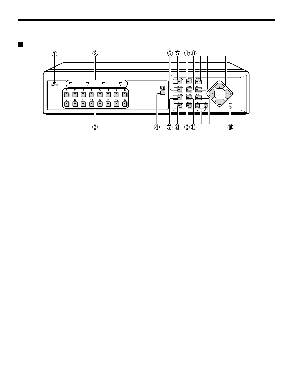
PART NAMES
Front
(MPX-CD163)
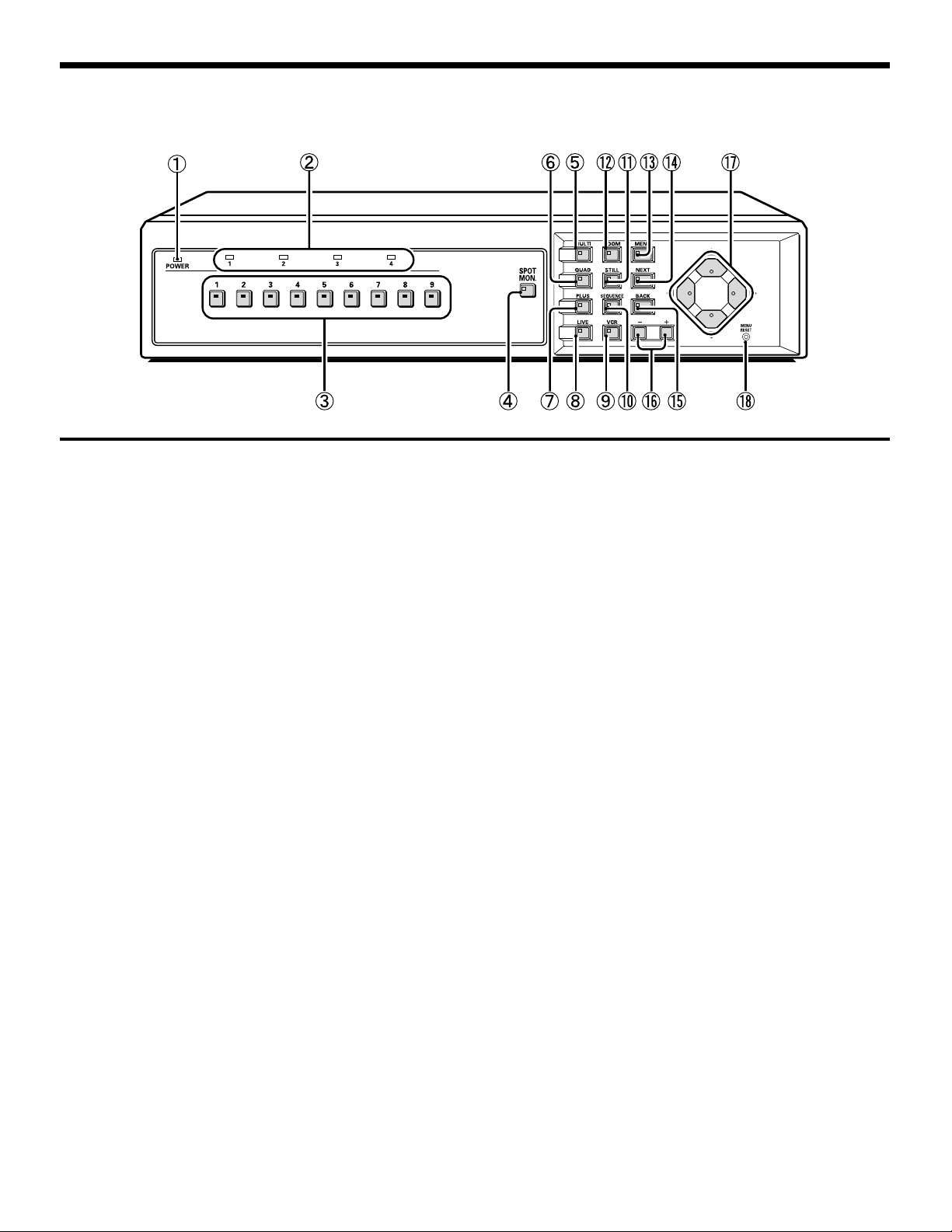
PART NAMES
(MPX-CD93)
9 Video playback button and indicator (VCR)
Press this button to play back recorded images. The
indicator will illuminate and the video playback images will
appear on the monitor.
F Automatic camera switching button and indicator
(SEQUENCE)
This button is used to automatically change the camera
image appearing in the single-screen, 4-screen or quarter
screen (plus screen) display.
When the SEQUENCE button is pressed, the indicator
flashes and the screen changes automatically. The camera
indicator also changes to match the images on the screen.
G Still image button and indicator (STILL)
If this button is pressed while monitoring is being carried out
using the single-screen display, the indicator will flash and
the image will be paused. If the button is pressed once
more, the image returns to normal.
H Electronic zoom button and indicator (ZOOM)
If monitoring is being carried out using the single-screen
display, the image can be enlarged by 2x. When this button
is pressed, the indicator will flash and the 2x zoom screen
will be displayed.
I Menu button and indicator (MENU)
This button is used to display the menu screen.
L Setting buttons (+, –)
These buttons are used to change the setting values in the
•
menu screens (setting screens).
If a coaxial cable camera (such as a dome-type camera) is
•
connected, these buttons can be used to carry out zoom
operation.
Furthermore, if these buttons are pressed after a camera
select button, manual focus adjustment is possible. They
can also be used to adjust the playback speed when
recorded images from a digital video recorder are being
played back.
M Cursor buttons
These buttons can be used to select items while a menu screen
•
(setting screen) is displayed.
If a camera that can be controlled via a coaxial cable (such as a
•
dome-type camera) is connected, these buttons can be used to
carry out pan and tilt operations.
They can also be used to carry out playback, stop, pause and
•
reverse operations when recorded images from a digital video
recorder are being played back.
N Menu reset/Clock adjust button (MENU RESET)
If this button is pressed while a menu screen (setting
screen) is displayed, the settings in the currently-displayed
menu screen are reset to their default values.
If this button is pressed while monitoring camera images,
the clock is adjusted and the minutes and seconds are
reset to 00.
J Next screen button and indicator (NEXT)
If this button is pressed while a menu screen is displayed, a
•
sub-menu setting screen is displayed.
If a camera that can be controlled via a coaxial cable (such as a
•
dome-type camera) is connected, this button can be used for
one-touch focus adjustment. Playback of recorded images from
multiple digital video recorders is carried out by selecting the
images at the digital video recorders.
K Cancel/display button and indicator (BACK)
If this button is pressed while a sub-menu screen is displayed,
•
the screen returns to the previous level menu screen.
If this button is pressed while monitoring camera images, the
•
on-screen displays (such as titles) can be turned on and off.
– 6 –
English
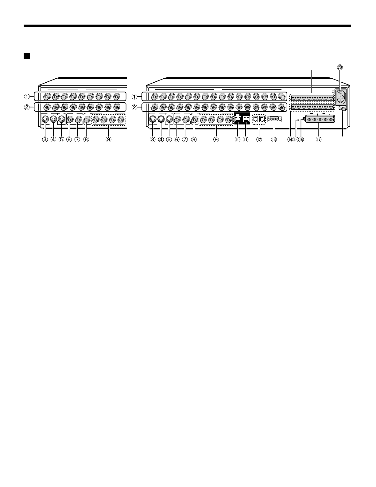
PART NAMES
Rear
(MPX-CD93) (MPX-CD163)
1234567 98
IN
OUT
MAIN
VCR
IN
OUT
MONITOR
S-VIDEO
CAMERA
MAIN
VCR
MONITOR
IN
SPOT MONITOR
21OUT
34
123
IN
OUT
VCR
OUT
IN
S-VIDEO
4 5 6 7 9 101112131415168
MAIN
VCR
MONITOR
IN
MAIN
MONITOR
CAMERA
SPOT MONITOR
2
1OUT
34 A
DIGITAL
OUT
DO NOT CONNECT TO PHONE LINE
RS485
SW IN
RS485
ALARM OUT REMOTE
A B C C R1 R2 C C
CONTROL
AC IN
ALARM IN
C
12345678910IN11 12 13 14 15 16
SENSOR
ALARM OUT
RS485
B
RS232C
TERMINATE
C
ON
ALL
RESET
OFF

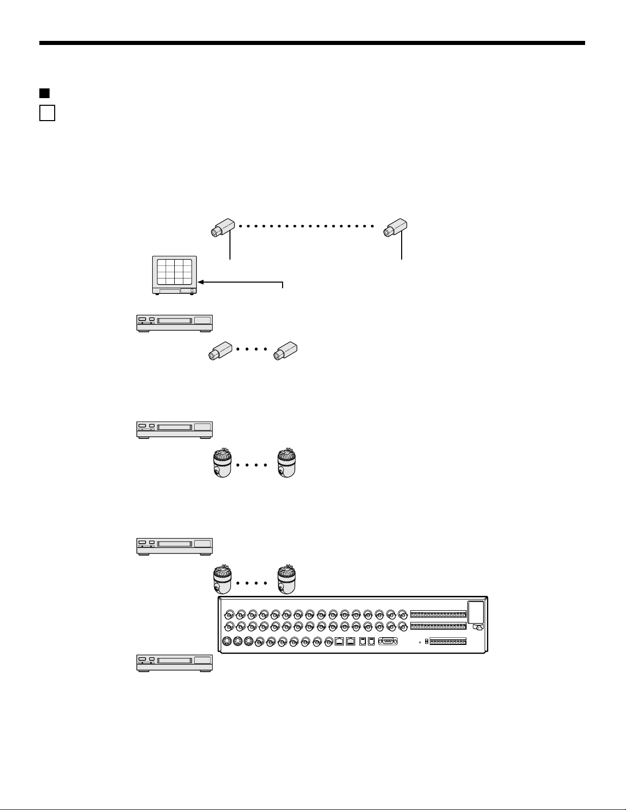
CONNECTIONS
Turn off the power for all components before connecting them.
Be sure to carefully read the Instruction Manual for all equipment being connected to the multiplexer.
If the connections are incorrect, smoke or operating malfunctions may result.
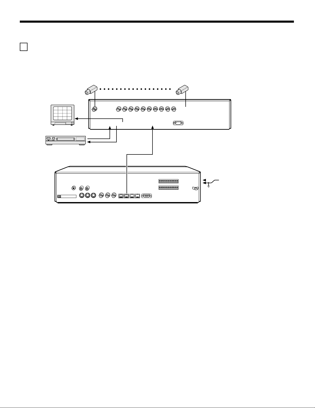
Basic connections (MPX-CD163 model)
Nine cameras can be connected to the MPX-CD93 model.
VIDEO IN connector
2
1
3
4
6
5
7
8
10
9
11
12
14
13
15
16
TV monitor (sold separately)
RS-485 connector
System controller (sold separately)
ALARM IN connector
Ground (C)
Time lapse VCR (sold separately)
Ground (C)
Switch output connector
Connecting high image quality (S-VHS) video equipment
S-VIDEO OUT connector S-VIDEO IN connector
Time lapse VCR (sold separately)
S-VIDEO IN connector
4
3
1
2
8
7
5
6
12
11
9
10
16
15
13
14
– 8 –
English
CONNECTIONS
Digital connections
A Digitally connecting four multiplexers
Up to four of these units can be connected for monitoring.
By connecting several units, up to 64 cameras can be viewed with one main monitor. Also, by connecting a recorder to each
multiplexer, playback of recorded images can be viewed on the main monitor.
* For the MPX-CD93 model, the total number of cameras that can be viewed with one monitor is 36, nine to each unit.
Use straight-type CAT-5 RS485 cables (sold separately) to connect the DIGITAL IN connectors to the digital output connectors of
other devices.
Use cables with a length of 3 m or less.
2
1
3
4
6
5
7
8
10
9
11
12
14
13
15
16
Note: (Main unit and sub-units)
Main unit and sub-units must be specified. Distinguishing a main unit and sub-units enables the main unit to display the camera
•
images of a sub-unit on the monitor. (See page 50.)
Since no video signal is output from the main monitor output connector on the rear panel of a sub-unit, if a monitor is connected the
•
screen will be black.
If these connections have been made, a digital video recorder cannot be connected digitally.
•
CONNECTIONS
B Digitally connecting the multiplexer and a digital video recorder
This unit and a digital video recorder can be connected digitally to provide high-resolution playback of recorded images.
Use straight-type CAT-5 RS485 cables (sold separately) to connect the DIGITAL IN connectors to the digital output connectors of
other devices.
Use cables with a length of 3 m or less.
2
1
3
4
6
5
7
8
10
9
11
12
14
13
15
16
Digital video recorder (sold separately)
CONNECTIONS
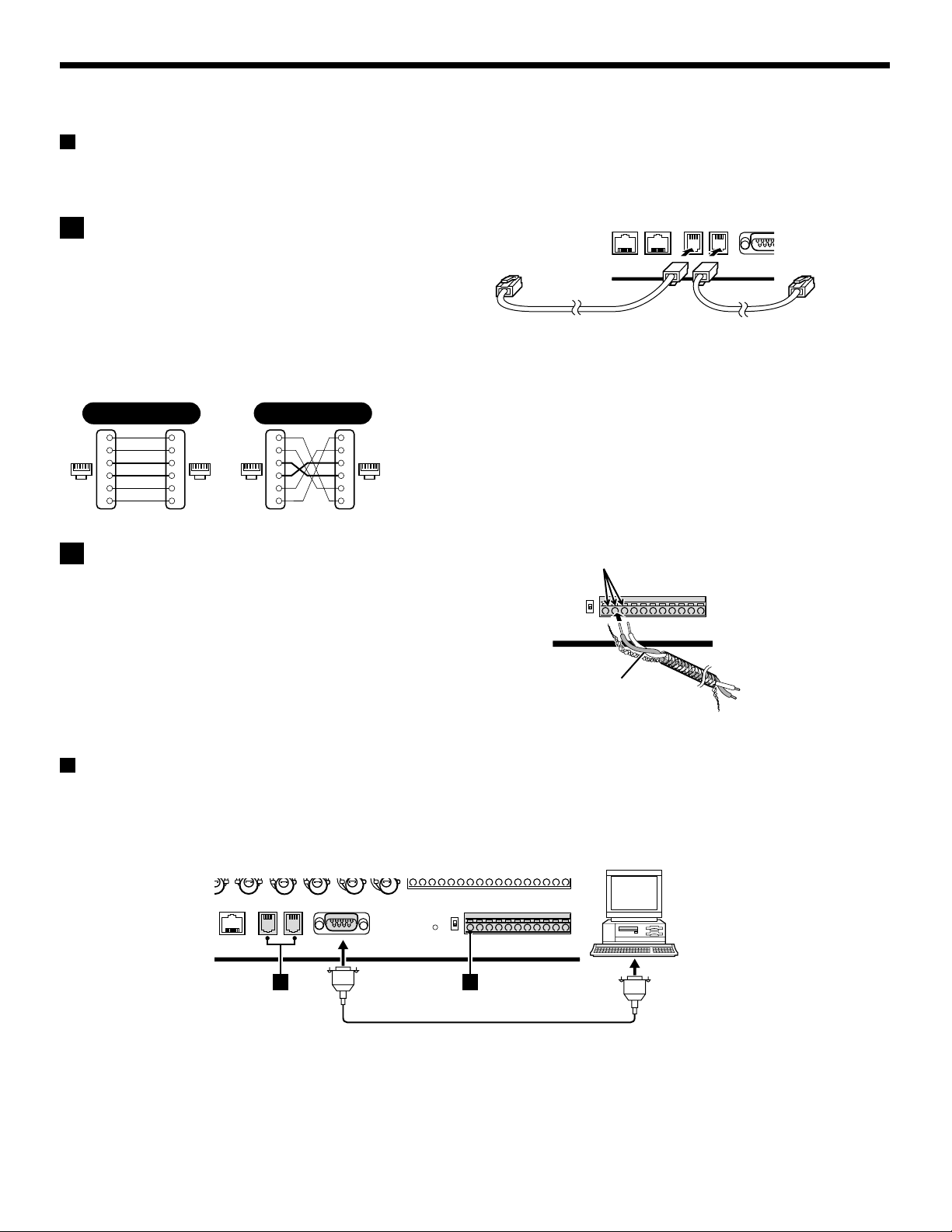
System control connections
Use the RS485 connector or the CONTROL connector to connect a system controller to the multiplexer. After connecting the system
controller, you will need to carry out the settings that are given in the CONTROL SET menu. (See page 72.)
A When using the RS485 (RJ-11) connector
Connect modular cables (sold separately) to the RS485 control
connectors at the rear of the multiplexer.
• If using a straight-type cable
Connect connector A to connector A and connector B to
connector B.
• If using a cross-type cable
Connect connector A to connector B and connector B to
connector A.
Straight type Cross type
Spare
Spare
Spare
Spare
1
2
3
4
5
6
1
2
61616116
3
4
5
6
Spare
1
Spare
2
3
4
5
Spare
6
Spare
1
2
3
4
5
6
To other
connector A
Straight-type cable Cross-type cable
To other
connector A
B When using the CONTROL connector (A/B)
Push the cable in.
Connect a twisted-pair cable (sold separately) to the A, B and C
(ground) terminals of the CONTROL connector at the rear of the
multiplexer. Connect signal A to signal A and signal B to signal B.
Twisted-pair cable
Ground
To signal B
To signal A
Computer control
When connecting the multiplexer to a computer (sold separately), use a D-Sub 9-pin cable (sold separately) to connect the RS-232C
connector to the computer. After connecting, you will need to carry out the settings that are given in the CONTROL SET menu. (See
page 72.)
Computer
A B
English
– 11 –
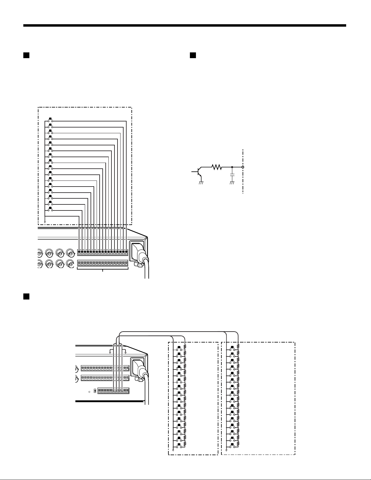
CONNECTIONS
External alarm sensor setup
In order to make an external alarm sensor operate, an external
switch must be connected to an ALARM IN connector. When an
intruder activates the external switch (such as by opening a
door), an alarm signal is received and an alarm can be made to
sound.
The MPX-CD93 model uses the connectors marked *.
Connect an external switch
to an ALARM IN connector
*
*
*
*
*
*
*
*
*
Using as a monitor board during a
motion sensor alarm
When the motion sensor built into the multiplexer responds to an
alarm, it outputs an alarm signal to the SENSOR ALARM OUT
connector. If a switching circuit such as a warning lamp is
connected to this connector, the warning lamp will illuminate
when there is a response from the motion sensor. If the warning
lamp is fixed somewhere in the layout diagram for an area such
as a factory, the location of the camera can be ascertained in an
instant during an emergency. The connector is always open.
The pin corresponding to the number of the camera that
generates a sensor response switches to Low.
1K
Rated values for each connector (at 25˚C)
• Max. current
• Max. voltage
• Max. power
25mA
25V
40mW
SENSOR ALARM OUT connector
Connecting a remote control circuit
If a remote control circuit is constructed as shown in the illustration and connected to the remote control input (R1 and R2) terminals of
the CONTROL connector, the multiplexer can be operated by remote control. (Contact LOW input)
The MPX-CD93 model can control up to nine cameras.
R1 R2
220Ω
SW 17: Menu selection
220Ω
SW 18: Video playback
300Ω
SW 19: Live image
360Ω
SW 20: Multi display
470Ω
SW 21: Plus display
680Ω
SW 22: Auto camera switching
820Ω
SW 23: Electronic zoom
1.2kΩ
SW 24: Still image
1.8kΩ
SW 25: Spot monitor
2.2kΩ
SW 26: 4-screen display
3.3kΩ
SW 27: Next
4.7kΩ
SW 28: Previous
7.5kΩ
SW 29: +
13kΩ
SW 30: –
27k
SW 31: 3
68kΩ
SW 32: 2
SW: Switch
Note:
The remote control cable should
be no more than 5 m long.
220Ω
SW 1: Camera1
220Ω
SW 2: Camera2
300Ω
SW 3: Camera3
360Ω
SW 4: Camera4
470Ω
SW 5: Camera5
680Ω
SW 6: Camera6
820Ω
SW 7: Camera7
1.2kΩ
SW 8: Camera8
1.8kΩ
SW 9 : Camera9
2.2kΩ
SW 10 : Camera10
3.3kΩ
SW 11 : Camera11
4.7kΩ
SW 12 : Camera12
7.5kΩ
SW 13 : Camera13
13kΩ
SW 14 : Camera14
27kΩ
SW 15 : Camera15
68kΩ
SW 16 : Camera16
– 12 –
English
MONITORING FUNCTIONS
Following is a summary of the operations that can be carried out while monitoring camera images. Refer to the corresponding page
numbers for more detailed explanations.
Viewing camera images
(See page 15.)
The following operations can be carried out while monitoring camera images and when playing back images that have been recorded.
Viewing recorded images
(See page 23.)
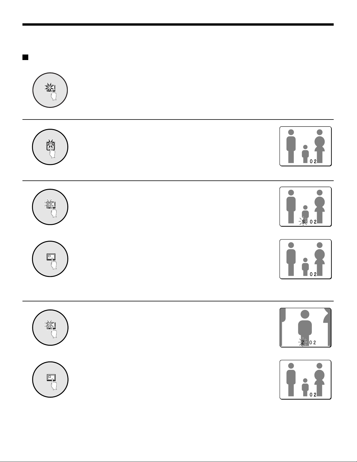
◆ Viewing a single-screen image (See page 15.)
ZOOM
4
Single-screen
STILL
Zoom
Still image
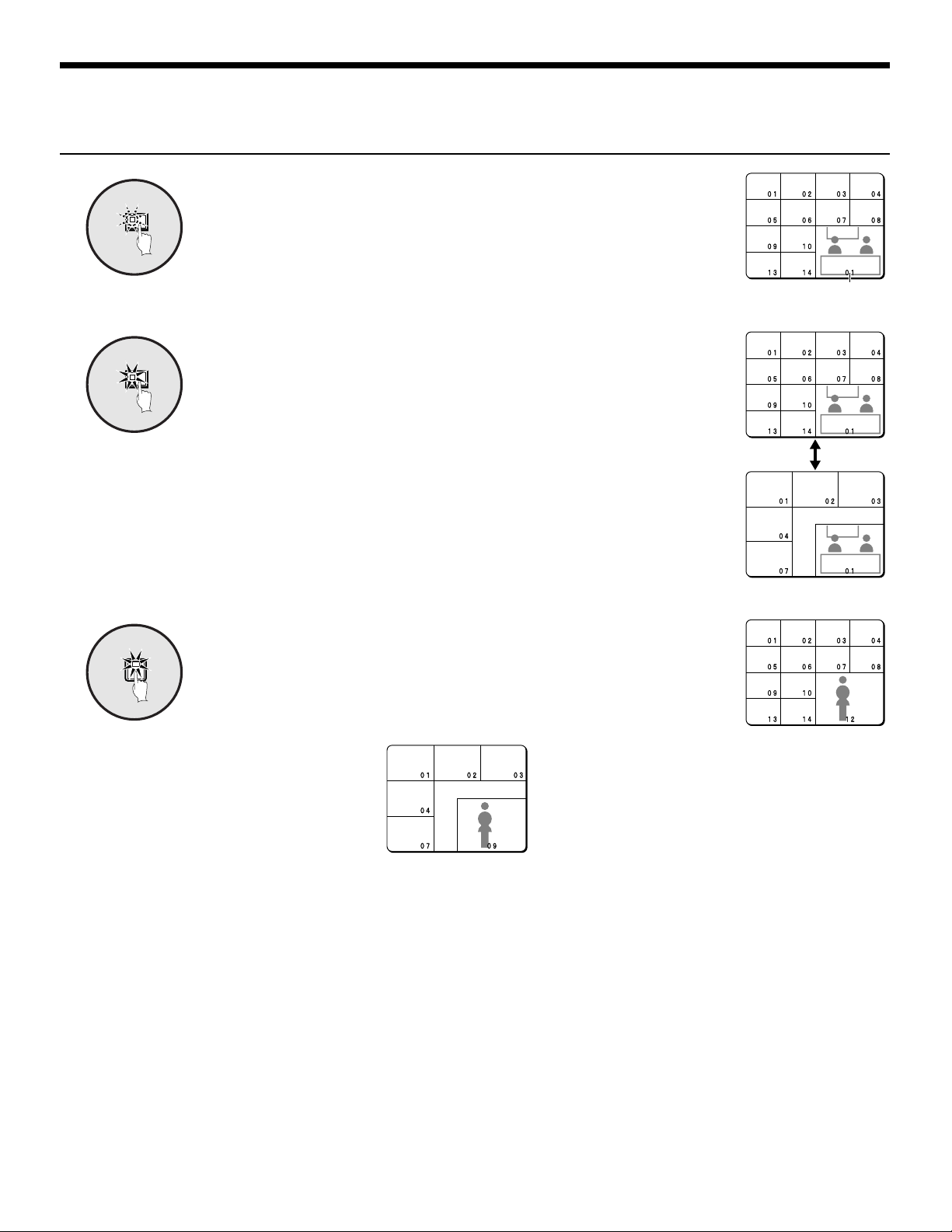
◆ Viewing multiple-screen images (See page 18.)
◆ Viewing automatically switching images (See page 20.)
For the MPX-CD93 model, a 9-screen display will appear.
MONITORING FUNCTIONS
VIDEO LOSS
VIDEO LOSS
Alarm function
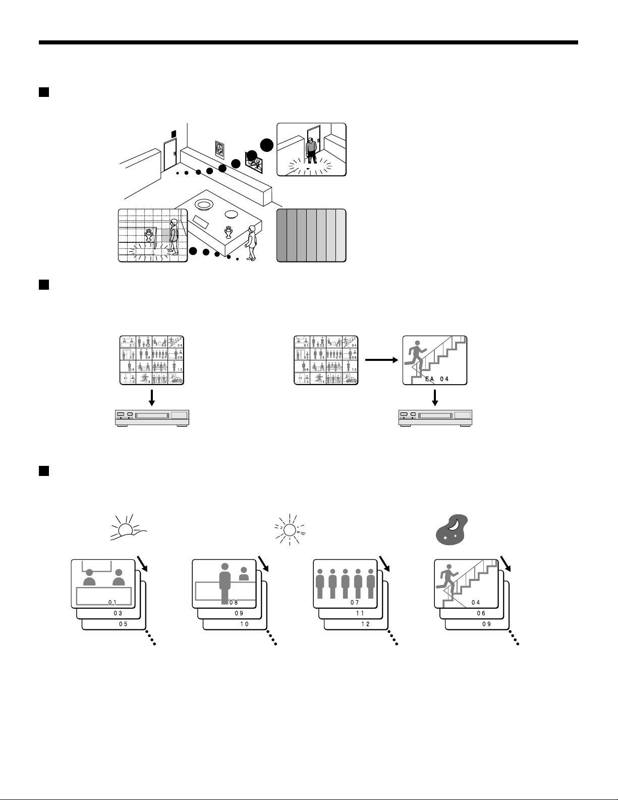
Suspicious people can be detected while monitoring by using the alarm setting function. (See page 60.)
External alarm sensor
Motion sensor alarm
(See page 67.)
A A
A A
CAMERA 4
CAMERA 1
VIDEO LOSSVIDEO LOSS
External alarm (See page 12.)
Signal loss detection alarm
(See page 68.)
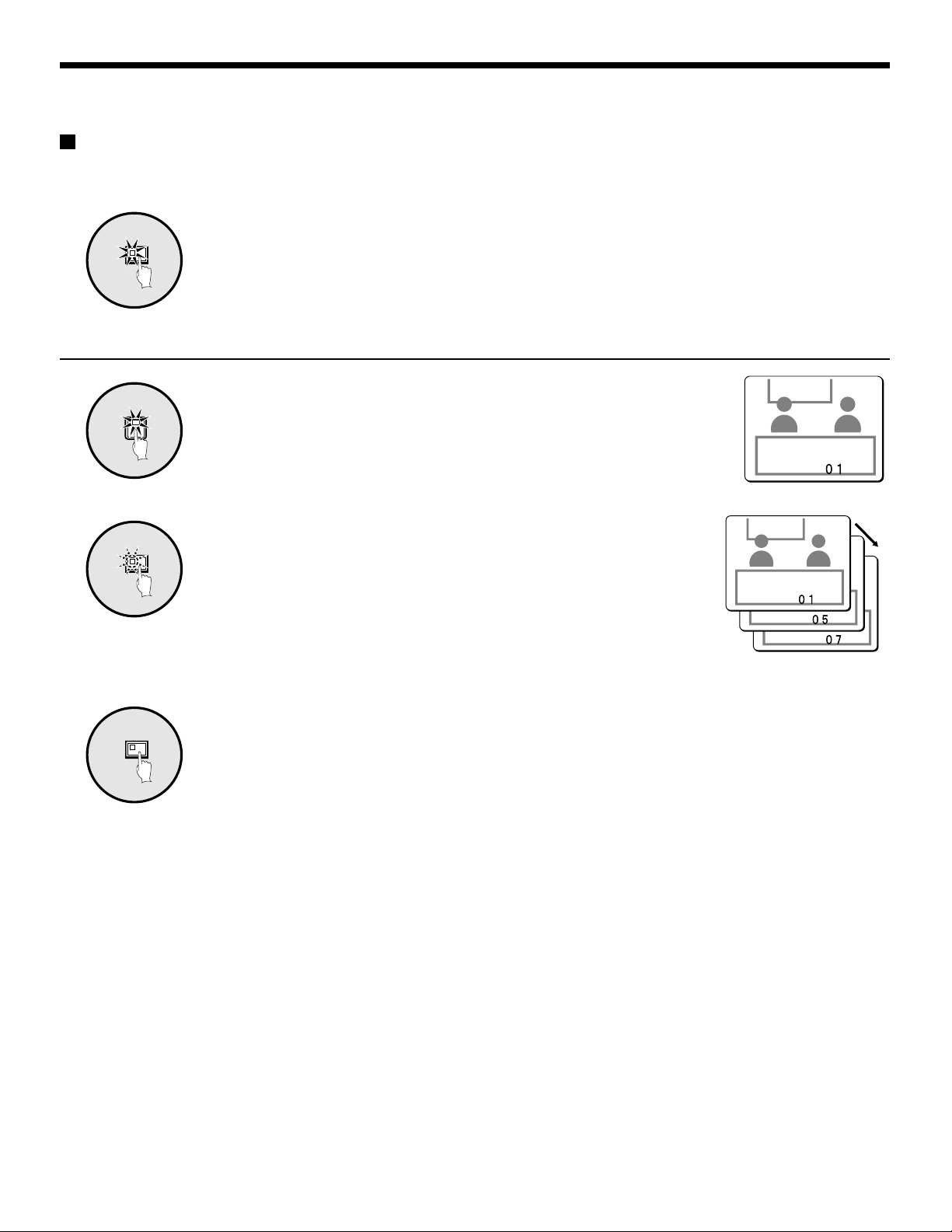
Recording function
A video recording device can be used to record camera images and alarm images taken during monitoring.
Program recording (See page 56.) Active recording (See page 64.)
VCR
Monitor
Monitor
VCR
Monitor
Records camera images Recording priority is given to alarm images.
Timer function
By using the timer function, a single day can be divided into four different time and each camera can be operated separately during
each time zone.
Morning Afternoon Night
Timer 1 Timer 2 Timer 3 Timer 4
6:00 – 11:00 11:00 – 13:00 13:00 – 18:00 18:00 – 6:00
Images from cameras
1, 3, 5 and 6 are
switched automatically
Images from cameras
8, 9, 10 and 16 are
switched automatically
Automatic switching display and recording of different camera images can be specified for each time zone.
Furthermore, if sensor alarms are set, intruders can be detected during those time zones.
Timer setting (See page 36.)
•
Using the timer function for automatic switching display (See page 45.)
•
Using the timer function to record images (See page 58.)
•
Using the timer function to detect motion alarms (See page 67.)
•
Using the timer function to cover the camera image with a gray pattern (See page 48.)
•
– 14 –
Images from cameras
7, 11, 12 and 13 are
switched automatically
Images from cameras
4, 6, 9, 12 and 16 are
switched automatically
English
VIEWING CAMERA IMAGES
Viewing a single-screen image
Press the LIVE button.
LIVE
Setting the camera image to single-screen display
2
Pausing images
The camera image appears as a split-screen.
Press a camera select button (example: 2).
The camera 2 image appears as a single-screen.
1
STILL
2
STILL
Press the STILL button.
The image will be paused.
To cancel the still image, press the STILL button once more.
Pausing will be canceled and normal images will appear.
Note: If you press the ZOOM button while the image is paused, the still image
will be enlarged. To return to the original still image, press the ZOOM
button once more.
STILL STILLZOOM
English
– 15 –
VIEWING CAMERA IMAGES
Enlarging images
Press the ZOOM button.
ZOOM
1
The images will be enlarged.
Note: If you set a zoom frame, the area of the image inside the zoom frame will
be enlarged. (See page 17.)
If you press the camera select button while
zooming, the image will be easier to see due to
Image with little
movement
the movement of the subject. The following
changes will occur if you press the camera
select button repeatedly.
2
• An image with little movement (almost a still image)
Large subjects become clearer and moving subjects
appear a little rough.
• An image with large movement (normal viewing)
The image of a moving subject becomes clearer and
subjects with little movement appear a little rough.
To return an enlarged image to normal image display, press the
ZOOM
2
ZOOM button once more.
The zoom will be canceled and normal images will appear.
Enlarged image is a
little rough
Image with large
movement
Enlarged image is a
little rough
Subject becomes
clearer
4
Subject becomes
clearer
– 16 –
English
VIEWING CAMERA IMAGES
Example: To zoom in on the camera 2 image and move the zoom frame
You can select the zoom position by means of the zoom frame which appears on the screen. The position of the zoom frame is initially
set to the middle of the screen.
Press camera select button 2.
2
1
ZOOM
2
The camera 2 image will appear in a single-screen display.
Press the ZOOM button.
The images will be enlarged.
Press and hold camera select button 2 for about 3 seconds or
more.
The zoom will be canceled and the normal image will appear, and the zoom
frame (G) will appear on the screen.
Note: If the zoom frame remains on the screen for about 10 seconds without
being adjusted, the screen will return to zoom display.
To make the zoom frame reappear, press and hold camera select button
2 again for 3 seconds or more.
Press the cursor button to move the zoom frame to the position
you wish to enlarge.
Press camera select button 2 once more.
The image in the repositioned zoom frame will be enlarged.
Note: If you press the STILL button while the images are being zoomed, an
enlarged still image will be displayed.
To return an enlarged image to normal image display, press the
ZOOM button once more.
The zoom will be canceled and normal images will appear.
VIEWING CAMERA IMAGES
Viewing multiple-screen images
Images from the cameras that are connected to the multiplexer can be displayed in several split-screen formats. Furthermore, the
images from each camera can be displayed in any position within the split screen. (See page 41.)
Press the LIVE button.
LIVE
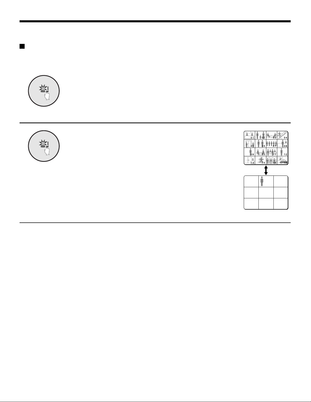
Viewing images as 9-screen or 16-screen displays
Press the MULTI button.
MULTI
The display switches between 9-screen and 16-screen displays each time the
MULTI button is pressed.
To return to a single-screen display, press a camera select button.
For the MPX-CD93 model, only the 9-screen display is available with no
switching.
Viewing images as a 4-screen display
Press the QUAD button.
Images appear as a 4-screen display.
Press the QUAD button once more.
Camera images are switched in 4-screen display units (1 – 4, 5 – 8,
9 – 12, 13 – 16) each time the button is pressed.
To return to a single-screen display, press a camera select button.
For the MPX-CD93 model, a 4-screen display of images from cameras
1 – 4, 5 – 8, or 9 – 3 will appear each time the button is pressed.
VIEWING CAMERA IMAGES
Plus screen viewing
The plus screen allows you to display the image from each
camera as a quarter-screen picture in the lower right corner of
the split-screen display, and images being recorded or played
back can be monitored.
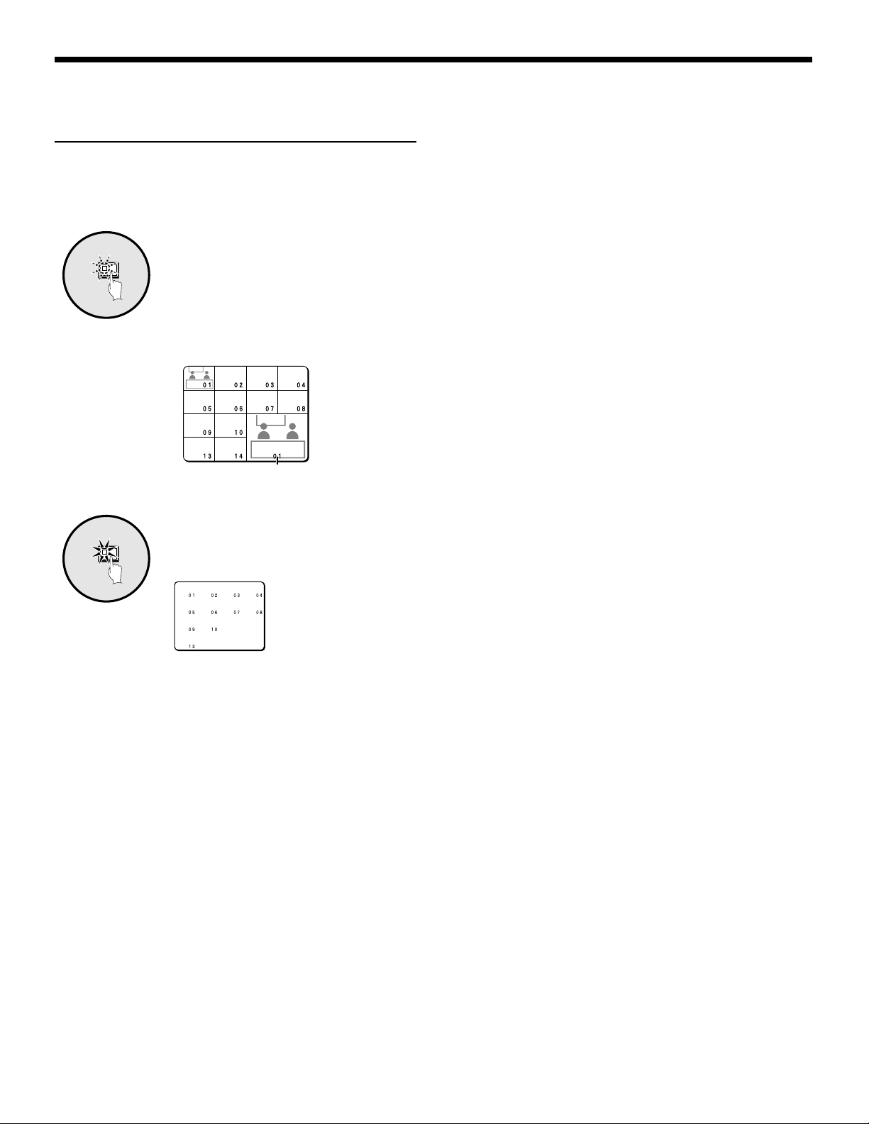
Press the PLUS button.
1
PLUS
The display changes to show a 13-screen
display with a plus screen as a
quarter-screen picture in the lower-right
corner.
For the MPX-CD93 model, a 6-screen
display appears.
Plus screen
2
MULTI
The display switches between 13-screen
and 6-screen each time the MULTI button
is pressed.
Press a camera select button
(example: 12).
The images from the selected camera will
be displayed in the plus screen. To cancel
the plus screen, press the PLUS button
once more.
For the MPX-CD93 model, press a
camera select button numbered 9 or less.
Press the MULTI button.

VIEWING CAMERA IMAGES
Viewing automatically switching images
The camera images are switched automatically in the order that has been set using the SEQUENCE settings. (See page 43.)
Press the LIVE button.
LIVE
Automatically switching of the single-screen images
Press the camera select buttons (example: 1, 5, 7) to select the
1
1
SEQUENCE
camera numbers for automatic switching.
The camera select buttons for the cameras that were selected are stored in
memory.
The indicator lamp will light up when the next button is pressed.
Press the SEQUENCE button.
Camera images will be switched automatically in the order 1, 5 and 7.
2
3
SEQUENCE
To cancel automatic switching, press the SEQUENCE button.
Automatic switching will be canceled and normal images will appear.
– 20 –
English
VIEWING CAMERA IMAGES
Automatically switching of the 4-screen images
Press the QUAD button.
QUAD
1
SEQUENCE
2
SEQUENCE
3
Images appear as a 4-screen display.
Press the SEQUENCE button.
Camera images will be switched automatically in 4-screen display units
(1 – 4, 5 – 8, 9 – 12, 13 – 16).
For the MPX-CD93 model, images from cameras 1 – 4, 5 – 8, or 9 – 3 will be
switched automatically.
Press the SEQUENCE button once more to return to the 4-screen
display.
Automatic switching will be canceled and 4-screen display will be restored.
Automatically switching of the plus screen image
Press the PLUS button.
PLUS
The plus screen is displayed.
1
Press the SEQUENCE button.
SEQUENCE
The camera images in the plus screen will be switched automatically.
2
Press the SEQUENCE button once more to return to the plus
SEQUENCE
3
screen.
Automatic switching will be canceled and the plus screen will appear.
To cancel the plus screen, press the PLUS button once more.
English
– 21 –
VIEWING CAMERA IMAGES
Displaying and automatically switching recorded images in the plus screen
Set the recording device to playback mode.
Press the PLUS button.
PLUS
1
VCR
2
SEQUENCE
3
The plus screen is displayed.
Press the VCR button.
This sets the plus screen to video playback mode.
Press the SEQUENCE button.
The playback images in the plus screen will be switched automatically.
4
SEQUENCE
Press the SEQUENCE button once more to return to the plus
screen.
Automatic switching will be canceled and the plus screen will appear.
To cancel the plus screen, press the PLUS button once more.
– 22 –
English
VIEWING RECORDED IMAGES
Playing back recorded images in a single-screen display
Press the VCR button to playback from the connected recorder.
VCR
Playing back in a single-screen
2
1
Pausing recorded images
STILL
1
Note: Start playback on the recorder. If the playback image was not recorded
through this unit, it will not be displayed correctly. “NO ID” will appear on
the screen.
Press a camera select button (example: 2).
The recorded images will be played back in a single-screen.
Press the STILL button.
The image will be paused.
To return a still image to normal image display, press the STILL
STILL
2
button once more.
Pausing will be canceled and normal images will appear.
Note: If you press the ZOOM button while an image is paused, the still image
Enlarging recorded images
Press the ZOOM button.
ZOOM
1
ZOOM
2
The images will be enlarged.
Note: If you set a zoom frame, the area of the image inside the zoom frame will
To return an enlarged image to normal image display, press the
ZOOM button once more.
The zoom will be canceled and normal images will appear.
will be enlarged. To return to the original still image, press the ZOOM
button once more.
be enlarged. (See page 24.)
English
– 23 –

VIEWING RECORDED IMAGES
Example: To zoom in on a specific part of the camera 2 image
You can use the zoom frame that appears on the screen to select the position you wish to enlarge. The zoom frame is set initially at
the center of the screen.
Press camera select button 2.
2
1
ZOOM
2
2
3
The camera 2 image will appear in a single-screen display.
Press the ZOOM button.
The images will be enlarged.
Press and hold camera select button 2 for about 3 seconds or
more.
The zoom will be canceled and the normal image will appear, and the zoom
frame (G) will appear on the screen.
Note: If the zoom frame remains on the screen for about 10 seconds without
being adjusted, the screen will return to zoom display.
To make the zoom frame reappear, press and hold camera select button
2 again for 3 seconds or more.
Press the cursor button to determine the position you wish to
enlarge.
4
Press camera select button 2 one more.
2
5
ZOOM
The area of the image inside the zoom frame will be enlarged.
Note: If you press the STILL button while the images are being zoomed, an
enlarged still image will be displayed.
Press the ZOOM button once more to return the enlarged image to
the normal image.
The zoom will be canceled and normal images will appear.
6
– 24 –
English

VIEWING RECORDED IMAGES
Playing back multiple-screen displays
Recorded images can be displayed in several split-screen formats. Furthermore, the images from each camera can be displayed in
any position within the split-screen. (See page 41.)
Press the VCR button.
VCR
Playing back images as 9-screen or 16-screen displays
Press the MULTI button.
The display switches between 9-screen and 16-screen each time the MULTI
button is pressed.
To return to a single-screen display, press a camera select button.
For the MPX-CD93 model, only the 9-screen display is available with no
switching.
Playing back images as a 4-screen display
Press the QUAD button.
Images appear as a 4-screen display.
Press the QUAD button once more.
Camera images are switched in 4-screen display units (1 – 4, 5 – 8,
9 – 12, 13 – 16) each time the button is pressed.
To return to a single-screen display, press a camera select button.
For the MPX-CD93 model, a 4-screen display of images from cameras
1 – 4, 5 – 8, or 9 – 3 will appear each time the button is pressed.
VIEWING RECORDED IMAGES
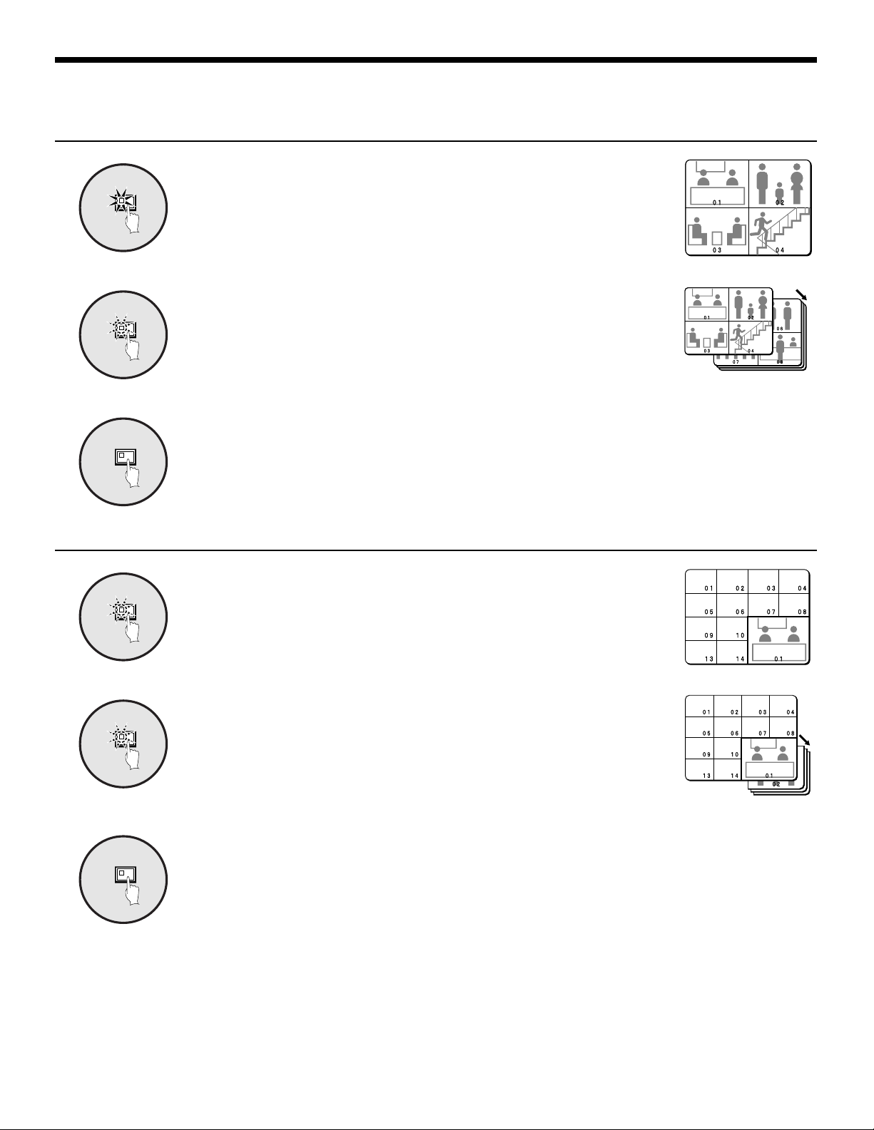
Playing back images as 13-screen or 6-screen displays (plus screen)
Press the PLUS button.
PLUS
1
MULTI
2
The display changes to show a 13-screen or 6-screen display with a plus
screen as a quarter-screen picture in the lower-right corner.
Press the MULTI button.
The display switches between 13-screen and 6-screen each time the MULTI
button is pressed.
For the MPX-CD93 model, only the 6-screen display is available with no
switching.
Plus screen
Press a camera select button (example: 12).
12
3
The playing back images from the selected camera will be displayed in the plus
screen.
To cancel the plus screen, press the PLUS button once more.
For the MPX-CD93 model, press camera select button 9.
– 26 –
English
VIEWING RECORDED IMAGES
Playing back automatically switching images
Recorded images are switched automatically in the order that has been set using the SEQUENCE settings. (See page 43.)
Press the VCR button.
VCR
Automatic switching of the single-screen playback images
Press the camera select buttons (example: 1, 5, 7).
1
1
Press the SEQUENCE button.
SEQUENCE
The recorded images are automatically switched in the order set.
2
3
SEQUENCE
To cancel automatic switching, press the SEQUENCE button once
more.
Automatic switching will be canceled and normal images will appear.
English
– 27 –

VIEWING RECORDED IMAGES
Automatically switching of the 4-screen playback images
Press the QUAD button.
QUAD
1
SEQUENCE
2
SEQUENCE
3
Images appear as a 4-screen display.
Press the SEQUENCE button.
Camera images will be switched automatically in 4-screen display units
(1 – 4, 5 – 8, 9 – 12, 13 – 16).
For the MPX-CD93 model, images from cameras 1 – 4, 5 – 8, or 9 – 3 will be
switched automatically.
To cancel automatic switching, press the SEQUENCE button once
more.
Automatic switching will be canceled and a 4-screen display will appear.
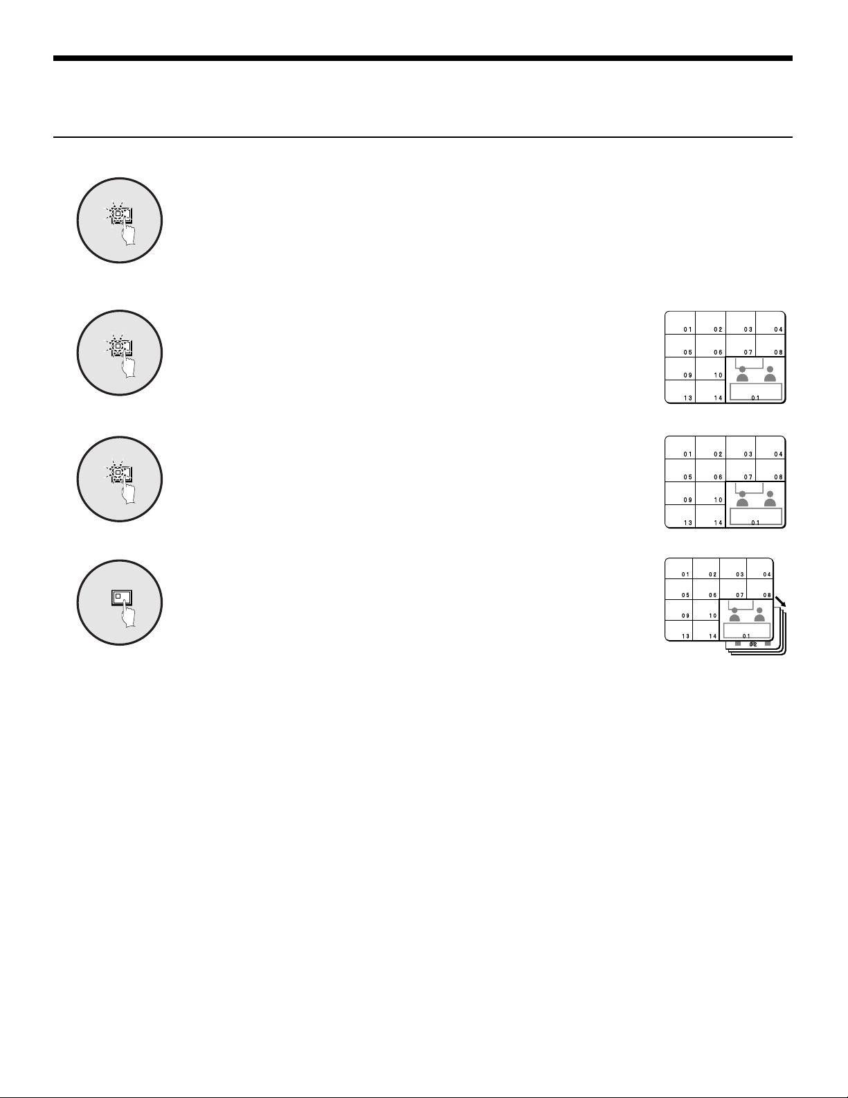
Automatically switching of the plus screen playback image
Press the PLUS button.
PLUS
The plus screen is displayed.
1
Press the SEQUENCE button.
SEQUENCE
The playback images in the plus screen will be switched automatically.
2
To cancel automatic switching, press the SEQUENCE button once
SEQUENCE
3
more.
Automatic switching will be canceled and a plus screen will appear.
To cancel the plus screen, press the PLUS button once more.
– 28 –
English

VIEWING WITH SPOT MONITOR
Four monitors can be connected to the spot monitor output connectors on the rear panel of this unit.
Even while the main monitor is showing camera images as split screens or playback, the camera images can be displayed on the spot
monitors as single-screen or automatic switching images.
Spot Monitor Button Functions
When the SPOT MON. button is pressed in camera image (LIVE) or playback (VCR) mode, each spot monitor goes into selection
standby condition.
If the SPOT MON. button is pressed once more, LIVE or VCR mode is enabled.
• Selection of spot monitor 1
• Selection of spot monitor 2
• Selection of spot monitor 3
• Selection of spot monitor 4

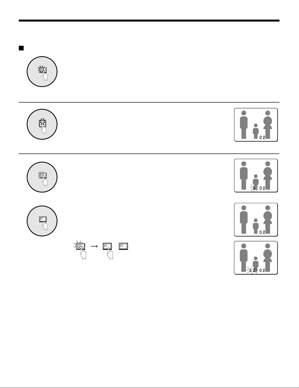
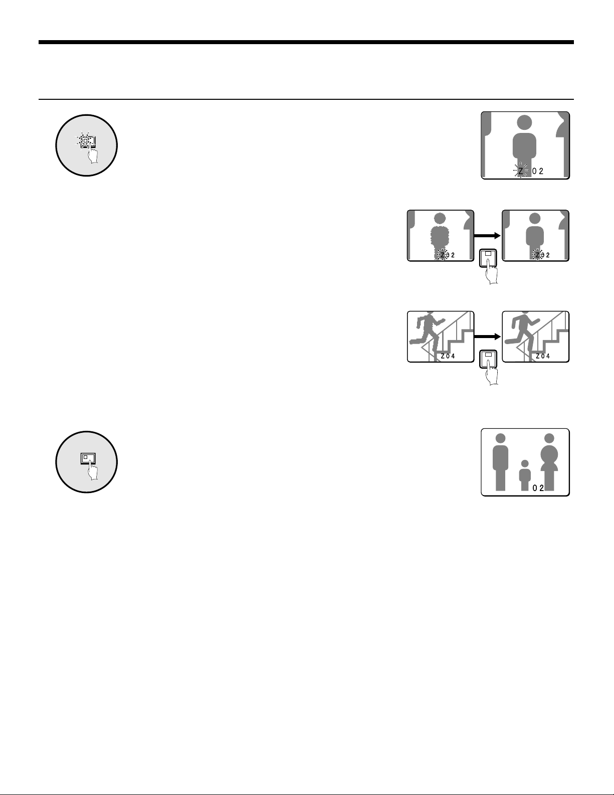
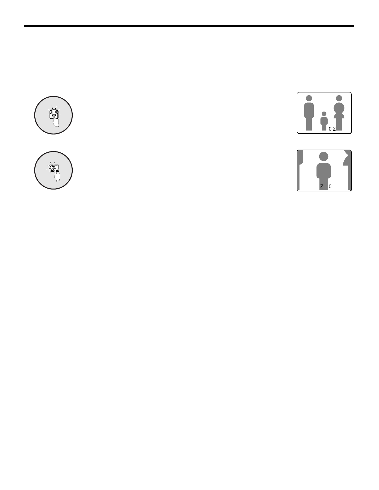
VIEWING WITH SPOT MONITOR
Spot monitor settings
Press the SPOT MON. button.
1
SPOT
MON.
Camera select buttons 1 to 4 flash and
spot monitor selection standby condition is
enabled.
Note:
If a button from 1 to 4 is pressed while
•
the indicators are flashing, the spot
monitor corresponding to the number of
the button pressed will be selected.
If MAIN → SPOT1 on the DISPLAY
•
SET menu are ON, the spot monitor 1
image will be the same as the main
monitor screen.
2
SPOT
4
MON.
(example: 4).
Spot monitor indicator 4 and the SPOT
MON. indicator will flash and S4 will
appear (flashing) on the screen of spot
monitor 4.
Note: S1 to S4 will appear flashing on the
screen of each selected spot
monitor.
Press a camera select button

MENU FLOWCHART AND MENU OPERATIONS
Menu flowchart
(LANGUAGE)
ENGLISH
FRANCAIS
ESPANOL
(CLOCK SET)
01-01-2001 MON 00:00:00
TIMER ON ¤
DAY LIGHT ON ¤
NEXT
(*:NEXT)
(TIMER SET)
TIMER-A TIMER-B
T-1 00:00 T-1 00:00
T-2 00:00 T-2 00:00
NEXT
T-3 00:00 T-3 00:00
T-4 00:00 T-4 00:00
SEQUENCE A
PROGRAM REC A
MASK A
MOTION SENSOR A
(DAY LIGHT SET)
WEEK MON TIME
ON 1ST-SUN 04 02:00
OFF LST-SUN 10 02:00
NEXT
NEXT
(MAIN MENU)
1 LANGUAGE ¤
2 CLOCK SET ¤
3 DISPLAY SET ¤
4 VCR SET ¤
5 ALARM SET ¤
6 SECURITY SET ¤
7 CONTROL SET ¤
8 ALARM DATA ¤
(*:NEXT)
MENU
(DISPLAY SET)
TITLE DOWN ¤
MULTI SCREEN CHANGE¤
SEQUENCE INDIV.¤
MASK ON ¤
MAIN†SPOT1 OFF
NEXT
DIGITAL CONNECTION OFF
COLOR LEVEL AUTO
(*:NEXT)
(VCR SET)
RECORDER TLS
REC.SPEED 2 H
ALARM REC.SPEED 2 H
SW.IN EDGE ñ
REC.PICTURE 01
NEXT
PROGRAM REC. ONLY *
(*:NEXT)
(ALARM SET)
ALARM ON *
ACTIVE REC. ON *
MOTION SENSOR ON *
VIDEO LOSS OFF
NEXT
(*:NEXT)
(PROGRAM REC.SET)
T-1
IN IN
01:ON 09:ON
02:ON 10:ON
03:ON 11:ON
04:ON 12:ON
NEXT
05:ON 13:ON
05:ON 14:ON
07:ON 15:ON
08:ON 16:ON
(ALARM OPERATION SET)
ALARM EXT.OR M.SENSOR
DURATION INDIV.*
NEXT
RETRIGGER ON
ALARM LIST ON
BUZZER ON
ALARM DISPLAY ¤
(*:NEXT)
(ACTIVE REC.SET)
AL.REC.EXT.
REC.MODE MODE1
NEXT
NEXT
CAMERA NO.01
(POSITION SET)
QUAD
01 02 : 05 06
03 04 : 07 08
-------------
NEXT
09 10 : 13 14
11 12 : 15 16
(SEQUENCE SET)
MAIN MONITOR 1 S ¤
SPOT MONITOR-1 1 S ¤
SPOT MONITOR-2 1 S ¤
SPOT MONITOR-3 1 S ¤
SPOT MONITOR-4 1 S ¤
NEXT
QUAD 1 S
(*:NEXT)
(MASK SET)
T-1
IN IN
01:OFF 09:OFF
02:OFF 10:OFF
03:OFF 11:OFF
04:OFF 12:OFF
05:OFF 13:OFF
NEXT
06:OFF 14:OFF
07:OFF 15:OFF
08:OFF 16:OFF
--------
01
NEXT
(ALARM DATA) 1/ 1
CAM DATE TIME ITEM
English
(SEQURITY LOCK SET)
OPERATION
CODE 1111
LOCK ON
SETUP
NEXT
CODE 1111
LOCK ON
(CONTROL SET)
DATA SPEED 19200
ALARM SEND ON
RS232C/RS485 RS232C
NEXT
CAMERA CONTROL SANYO *
(*:NEXT)
NEXT
NEXT
– 31 –
----------------
----------------
----------------
----------------
----------------
----------------
----------------
----------------
----------------
---------------CAMERA NO.01 T-1 LEVEL:OFF MODE:A
SECURITY CODE ----
(CAMERA CONTROL SET)
IN IN
01:OFF 09:0FF
02:OFF 10:OFF
03:OFF 11:OFF
04:OFF 12:OFF
05:OFF 13:OFF
06:OFF 14:OFF
07:OFF 15:OFF
08:OFF 16:OFF
(ALARM DISPLAY SET)
ALARM DISPLAY FULL
DOUBLE ALARM LAST
(SPOT MONITOR SET)
SPOT MONITOR-1 ON
NEXT
SPOT MONITOR-2 ON
SPOT MONITOR-3 ON
SPOT MONITOR-4 ON

MENU FLOWCHART AND MENU OPERATIONS
Menu operations
Press the MENU button.
MENU
◆ Status of indicators when a menu screen is displayed
MENU
NEXT
The MAIN MENU screen will be displayed.
Note: The MAIN MENU screen will appear on the main monitor and on spot
monitor 1.
• While the MENU indicator is flashing
When the MENU button is pressed, the menu screen will be terminated.
• While the NEXT indicator is flashing
When the NEXT button is pressed, a sub-menu screen (the next level) will
appear.
(MAIN MENU)
1 LANGUAGE ¤
2 CLOCK SET ¤
3 DISPLAY SET ¤
4 VCR SET ¤
5 ALARM SET ¤
6 SECURITY SET ¤
7 CONTROL SET ¤
8 ALARM DATA ¤
(*:NEXT)
BACK
• While the BACK indicator is flashing
When the BACK button is pressed, the previous menu screen will be
restored.
MENU
(MAIN MENU)
1 LANGUAGE ¤
2 CLOCK SET ¤
3 DISPLAY SET ¤
4 VCR SET ¤
5 ALARM SET ¤
6 SECURITY SET ¤
7 CONTROL SET ¤
8 ALARM DATA ¤
(*:NEXT)
NEXT NEXT
(CLOCK SET)
01-01-2001 MON 00:00:00
TIMER ON ¤
DAY LIGHT OFF
BACK BACK
(*:NEXT)
MENU
(TIMER SET)
TIMER-A TIMER-B
T-1 00:00 T-1 00:00
T-2 00:00 T-2 00:00
T-3 00:00 T-3 00:00
T-4 00:00 T-4 00:00
SEQUENCE A
PROGRAM REC A
MASK A
MOTION SENSOR A
– 32 –
English

LANGUAGE SETTING
Language setting
(MAIN MENU)
1 LANGUAGE ¤
2 CLOCK SET ¤
3 DISPLAY SET ¤
4 VCR SET ¤
5 ALARM SET ¤
6 SECURITY SET ¤
7 CONTROL SET ¤
8 ALARM DATA ¤
(*:NEXT)
(LANGUAGE)
ENGLISH
FRANCAIS
ESPANOL
The multiplexer menu screens can be displayed in several languages (English, French or Spanish). The default language setting is
English.
LANGUAGE screen display
Press the MENU button.
1
MENU
2
NEXT
The MAIN MENU screen will be displayed.
(MAIN MENU)
1 LANGUAGE ¤
2 CLOCK SET ¤
3 DISPLAY SET ¤
4 VCR SET ¤
5 ALARM SET ¤
6 SECURITY SET ¤
7 CONTROL SET ¤
8 ALARM DATA ¤
(*:NEXT)
Use the cursor button to select
“LANGUAGE” and then press the
NEXT button.
The LANGUAGE screen will be displayed.
3
MENU
Use the cursor button to select the
language, and then press the
MENU button.
The selected language will be set.
The camera images will be displayed.
Press the MENU button.
4
(LANGUAGE)
ENGLISH
FRANCAIS
ESPANOL
(LANGUAGE)
ENGLISH
FRANCAIS
ESPANOL
English
– 33 –

CLOCK SET SETTINGS
(MAIN MENU)
1 LANGUAGE ¤
2 CLOCK SET ¤
3 DISPLAY SET ¤
4 VCR SET ¤
5 ALARM SET ¤
6 SECURITY SET ¤
7 CONTROL SET ¤
8 ALARM DATA ¤
(*:NEXT)
(CLOCK SET)
01-01-2001 MON 00:00:00
TIMER ON ¤
DAY LIGHT ON ¤
(*:NEXT)
Clock setting
Timer setting
Set the timer when using the timer function.
(TIMER SET)
TIMER-A TIMER-B
T-1 00:00 T-1 00:00
T-2 00:00 T-2 00:00
T-3 00:00 T-3 00:00
T-4 00:00 T-4 00:00
SEQUENCE A
PROGRAM REC A
MASK A
MOTION SENSOR A
Daylight saving setting
(DAY LIGHT SET)
WEEK MON TIME
ON 1ST-SUN 04 02:00
OFF LST-SUN 10 02:00
The CLOCK SET menu is used to set the time. It is also used to set a timer when using the timer function, and to make daylight saving
settings.
– 34 –
English

10-15-2002 15:20:00
CLOCK SET-1
CLOCK SET SETTINGS
Clock settings (default setting: 01-01-2001 MON 00:00:00)
Be sure to set the clock to the correct time.
The correct time must be set in order for the timer setting and summer time setting functions to work correctly.
Example: Setting the clock to October 15, 2002 at 3:20 PM
Press the MENU button.
1
MENU
The MAIN MENU screen will be displayed.
(MAIN MENU)
1 LANGUAGE ¤
2 CLOCK SET ¤
3 DISPLAY SET ¤
4 VCR SET ¤
5 ALARM SET ¤
6 SECURITY SET ¤
7 CONTROL SET ¤
8 ALARM DATA ¤
(*:NEXT)
• Press the setting buttons to set
the year (2002), then press the
cursor button.
• Press the setting buttons to set
the hours (15), then press the
cursor button.
• Press the setting buttons to set
the minutes (20), then press the
(CLOCK SET)
10-15-2002 TUE 00:00:00
(CLOCK SET)
10-15-2002 TUE 15:00:00
(CLOCK SET)
10-15-2002 TUE 15:20:00
cursor button.
2
NEXT
Use the cursor button to select
“CLOCK SET”, and then press the
NEXT button.
The CLOCK SET screen will be displayed.
(CLOCK SET)
01-01-2001 MON 00:00:00
TIMER ON *
DAY LIGHT OFF
Use the cursor button to select
3
“01”, and then use the setting
+–
buttons to set the date.
(CLOCK SET)
01-01-2001 MON 00:00:00
TIMER ON *
DAY LIGHT OFF
The time setting is finished.
Note: The day of the week will be automatically set according to
the date entered.
BACK
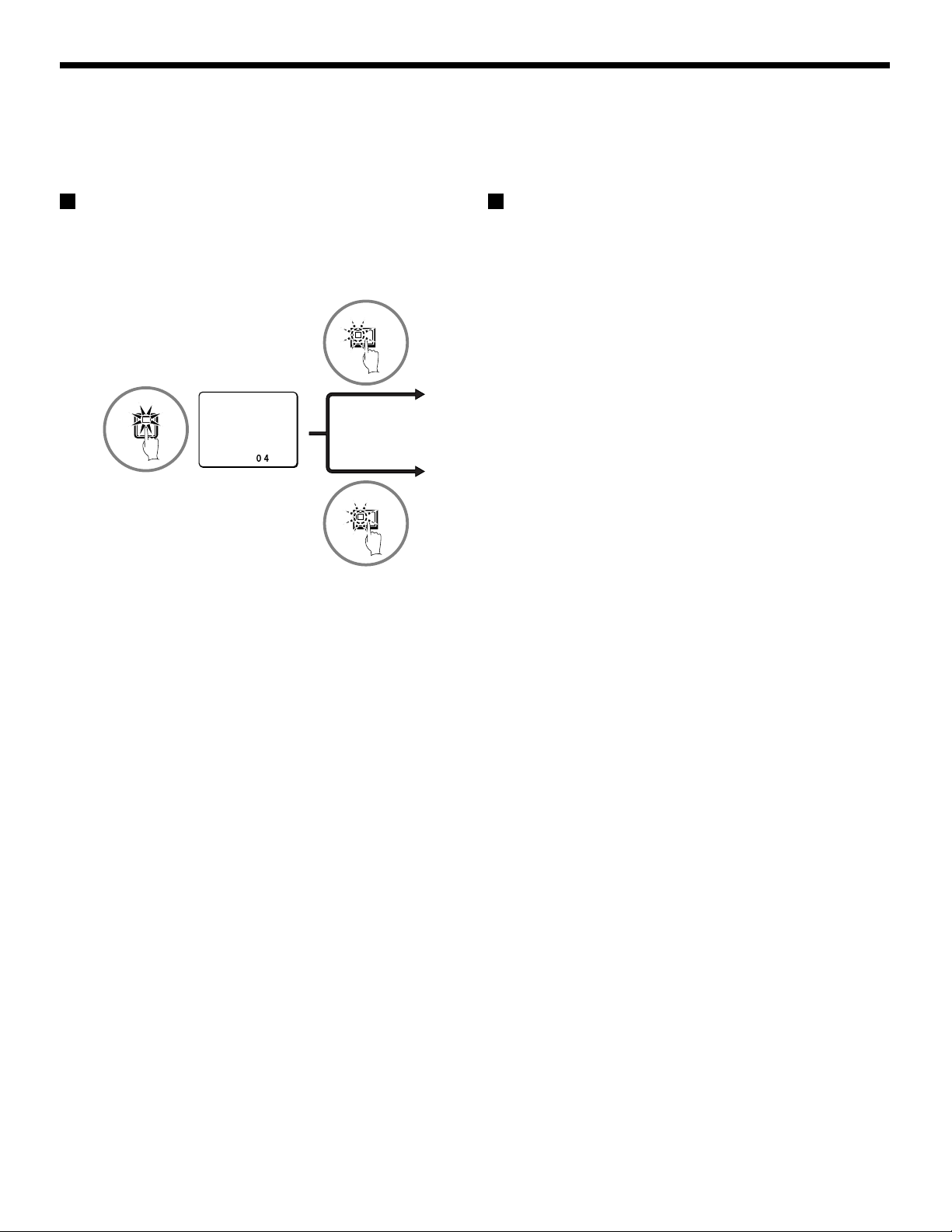
☞To display date, time and camera number
While the camera image is displayed, press the
BACK button repeatedly. The following actions
will occur:
Date and time
10-15-2002 15 : 20 : 00
Camera number
01
Date, time and camera number
10-15-2002 15 : 20 : 00
Cancel display
01
4
English
10-15-2002 15:20:00
01
Time is displayed.
• Press the setting buttons to set the
+–
month (10), then press the cursor
button.
(CLOCK SET)
10-01-2001 MON 00:00:00
☞Setting the time (minutes and seconds) to
00 during monitoring
Press the MENU RESET button. The minutes
and seconds will then be reset to 00.
• Press the setting buttons to set the
day (15), then press the cursor
button.
(CLOCK SET)
10-15-2001 MON 00:00:00
Note: These operations must only be carried out
while camera images are being displayed.
If you press these buttons while a menu
screen is being displayed, the setting values
will be reset to their defaults.
CLOCK SET-1
– 35 –

CLOCK SET SETTINGS
CLOCK SET-2
TIMER settings
(default setting: 00:00)
The timer function uses two separate timer settings (TIMER-A
and TIMER-B), and each timer setting can be made in four time
zones (example: midnight, morning, daytime, evening).
For example, TIMER-A time zones can be set for automatic
screen switching and TIMER-B time zones can be set for gray
pattern cover on camera images.
☞ Operable functions during the
period set by the timer
Each of the following menu settings is required to operate these
timer functions. After you have made the menu settings, be sure
to make the timer settings.
• To change camera images into
automatic switching screens.
Set “SEQUENCE” on DISPLAY
SET screen
• To cover camera images with
gray pattern.
Set “MASK” on DISPLAY SET
screen
• To record camera images on a
video unit
Set “PROGRAM REC” on VCR
SET screen
(DISPLAY SET)
TITLE DOWN ¤
MULTI SCREEN NORMAL
SEQUENCE INDIV.*
MASK ON *
MAIN†SPOT1 OFF
DIGITAL CONNECTION OFF
COLOR LEVEL AUTO
(*:NEXT)
(VCR SET)
RECORDER TLS
REC.SPEED 2 H
ALARM REC.SPEED 2 H
SW.IN EDGE ñ
REC.PICTURE 01
PROGRAM REC. ONLY *
(*:NEXT)
For these settings, set Example 2 consecutively with Example 1.
Example1: Set TIMER-A and TIMER-B time
zones as follows
(TIMER-A settings) (TIMER-B settings)
T-1 4 a.m. (4:00) T-1 6 a.m. (6:00)
T-2 6 a.m. (6:30) T-2 8 a.m. (8:00)
T-3 12:30 p.m. (12:30) T-3 2:30 p.m. (14:30)
T-4 6 p.m. (18:00) T-4 8 p.m. (20:00)
Press the MENU button, use the
1
MENU
2
3
NEXT
+–
cursor button to select CLOCK SET
and then press the NEXT button.
Use the cursor button to select
TIMER “OFF”.
(CLOCK SET)
10-15-2001 MON 15:20:00
TIMER OFF
DAY LIGHT
OFF
Press the setting buttons to select
“ON”, and then press the NEXT
button.
The TIMER SET screen will be displayed.
(CLOCK SET)
10-15-2001 MON 15:20:00
TIMER ON *
DAY LIGHT
OFF
• To detect an alarm input in a
camera image
Set “MOTION SENSOR” on
ALARM SET screen
(ALARM SET)
ALARM OFF
ACTIVE REC. OFF
MOTION SENSOR ON *
VIDEO LOSS OFF
(*:NEXT)
– 36 –
Use the cursor button to select
4
TIMER-A “T-1 00:” (hours), and then
+–
use the setting buttons to set the
hours to “4”.
(TIMER SET)
TIMER-A TIMER-B
T-1 04:00 T-1 00:00
T-2 00:00 T-2 00:00
T-3 00:00 T-3 00:00
T-4 00:00 T-4 00:00
CLOCK SET-2
English

CLOCK SET-3
CLOCK SET SETTINGS
Use the cursor button to select
5
+–
TIMER-A “T-1 :00” (minutes), and
then use the setting buttons to set
the minutes to “00”.
Example2: Set the timer operation as follows
☞To set TIMER-A time zones to automatic switching
screen and monitor mask.
☞To set TIMER-B timer zones to program recording and
(TIMER SET)
TIMER-A TIMER-B
T-1 04:00 T-1 00:00
T-2 00:00 T-2 00:00
T-3 00:00 T-3 00:00
T-4 00:00 T-4 00:00
6
+–
Use the cursor button to select
TIMER-A “T-2 00:” (hours), and then
use the setting buttons to set the
hours to “6”.
(TIMER SET)
TIMER-A TIMER-B
T-1 04:00 T-1 00:00
T-2 06:00 T-2 00:00
T-3 00:00 T-3 00:00
T-4 00:00 T-4 00:00
Use the cursor button to select
7
+–
TIMER-A “T-2 00” (minutes), and
then use the setting buttons to set
the minutes to “30”.
(TIMER SET)
TIMER-A TIMER-B
T-1 04:00 T-1 00:00
T-2 06:30 T-2 00:00
T-3 00:00 T-3 00:00
T-4 00:00 T-4 00:00
motion sensor.
1
2
3
Use the cursor button to select
SEQUENCE “A”, and then use the
+–
setting buttons to set “A”. (TIMER-A
setting)
SEQUENCE A
PROGRAM REC A
MASK A
MOTION SENSOR A
Use the cursor button to select
PROGRAM REC “A”, and then use
+–
the setting buttons to set “B”.
(TIMER-B setting)
SEQUENCE A
PROGRAM REC B
MASK A
MOTION SENSOR A
Use the cursor button to select
MASK “A”, and then use the setting
+–
buttons to set “A”.
Repeat steps 4 and 5 to set the
hours and minutes for T-3 and T-4
SEQUENCE A
PROGRAM REC B
MASK A
MOTION SENSOR A
also.
Use the same procedure to set the
8
+–
Note:
Initial settings T-1 to T-4 are “00:00”
•
In this case, the timer will operate at all times set by T-1.
The time divisions of the timer settings (T-1 to T-4) are
•
continuous settings in one cycle from start time to end time.
For instance, in the case of T-1 (4:00) and T-2 (6:30), the
domain of timer T-1 is from 4 a.m. until 6:30 a.m.
If two more timers are set to the same starting time, the
•
timers will operate together for the same period of time.
When setting the timers, a setting cannot be entered if, for
•
instance, T-3 as been set to earlier than T-1. If this happens,
re-enter the correct settings.
hours and minutes for T-1, T-2, T-3
and T-4.
(TIMER SET)
TIMER-A TIMER-B
T-1 04:00 T-1 06:00
T-2 06:30 T-2 08:00
T-3 12:30 T-3 14:30
T-4 18:00 T-4 20:00
4
Use the cursor button to select
MOTION SENSOR “A”, and then
+–
use the setting buttons to set “B”.
SEQUENCE A
PROGRAM REC B
MASK A
MOTION SENSOR A
5
BACK
Press the BACK button.
The setting will then be completed and the
display will return to the CLOCK SET
screen.
Press the BACK button once more to
return to the MAIN MENU screen.
CLOCK SET-3
English
– 37 –

CLOCK SET SETTINGS
CLOCK SET-4
DAY LIGHT setting
(default setting: OFF)
You can set the starting time and ending time for daylight.
When daylight is set, the time is automatically advanced by one
hour during the summer period.
☞
To make changes to the settings
Example: Setting the daylight from the
second Tuesday of May at 3:00
AM, to the fourth Tuesday of
September at 3:00 AM.
Press the MENU button, use the
1
MENU
2
cursor button to select CLOCK SET
and then press the NEXT button.
Use the cursor button to select
DAY LIGHT “OFF”.
(CLOCK SET)
10-15-2001 MON 15:30:00
TIMER OFF
DAY LIGHT OFF
4
+–
(DAY LIGHT SET)
WEEK MON TIME
ON 2ND-SUN 04 02:00
OFF LST-SUN 10 02:00
WEEK (2ND), then press the cursor
button.
Menu: 1ST, 2ND, 3RD, 4TH or LST
(first, second, third, fourth or
last)
• Press the setting buttons to set the WEEK (TUE),
• Press the setting buttons to set the
then press the cursor button.
Menu: SUN, MON, TUE, WED, THU, FRI or SAT
(DAY LIGHT SET)
WEEK MON TIME
ON 2ND-TUE 04 02:00
OFF LST-SUN 10 02:00
• Press the setting buttons to set the MON (05),
then press the cursor button.
Menu: 1, 2, 3, 4 ..... 11, 12
(for January, February, March ..... December)
(DAY LIGHT SET)
WEEK MON TIME
ON 2ND-TUE 05 02:00
OFF LST-SUN 10 02:00
• Press the setting buttons to set the TIME (03),
then press the cursor button.
(DAY LIGHT SET)
WEEK MON TIME
ON 2ND-TUE 05 03:00
OFF LST-SUN 10 02:00
Press the setting buttons to
3
NEXT
+–
change the setting to ON, and then
press the NEXT button.
The DAY LIGHT SET screen will be
displayed.
(CLOCK SET)
10-15-2001 MON 15:30:00
TIMER OFF
DAY LIGHT ON *
(*:NEXT)
5
+–
Following the same procedure as above,
set when the time is changed back from
daylight to standard time (the OFF
settings).
(DAY LIGHT SET)
WEEK MON TIME
ON 2ND-TUE 05 03:00
OFF 4TH-TUE 09 03:00
6
Press the MENU button.
The display will return to the normal screen.
CLOCK SET-4
– 38 –
English

DISPLAY SET SETTINGS
(MAIN MENU)
1 LANGUAGE ¤
2 CLOCK SET ¤
3 DISPLAY SET ¤
4 VCR SET ¤
5 ALARM SET ¤
6 SECURITY SET ¤
7 CONTROL SET ¤
8 ALARM DATA ¤
(*:NEXT)
(DISPLAY SET)
TITLE DOWN ¤
MULTI SCREEN CHANGE¤
SEQUENCE INDIV.¤
MASK ON ¤
MAIN†SPOT1 OFF
DIGITAL CONNECTION OFF
COLOR LEVEL AUTO
(*:NEXT)
CAMERA NO.01
-------
001
CAMERA NO.01 CAM
CAMERA NO.01 CAM
(MAIN MON.SEQ SET)
T-4
IN IN
01:ON 09:ON
02:ON 10:ON
03:ON 11:ON
04:ON 12:ON
05:ON 13:ON
06:ON 14:ON
07:ON 15:ON
08:ON 16:ON
DESK
DESK
001
001
(CLOCK SET)
01-01-2002 TUE 00:00:00
TIMER ON ¤
DAY LIGHT ON *
(*:NEXT)
(TIMER SET)
TIMER-A TIMER-B
T-1 00:00 T-1 00:00
T-2 00:00 T-2 00:00
T-3 00:00 T-3 00:00
T-4 00:00 T-4 00:00
SEQUENCE A
PROGRAM REC A
MASK A
MOTION SENSOR A
(PROGRAM REC.SET)
(PROGRAM REC SET)
T-1
(PROGRAM REC SET)
TIMER-1
IN IN
(PROGRAM REC SET)
TIMER-1
IN IN
01:ON 09:ON
TIMER-1
IN IN
01:ON 09:ON
02:ON 10:ON
IN IN
01:ON 09:ON
02:ON 10:ON
03:ON 11:ON
01:ON 09:ON
02:ON 10:ON
03:ON 11:ON
04:ON 12:ON
02:ON 10:ON
03:ON 11:ON
04:ON 12:ON
05:ON 13:ON
03:ON 11:ON
04:ON 12:ON
05:ON 13:ON
05:ON 14:ON
04:ON 12:ON
05:ON 13:ON
05:ON 14:ON
07:ON 15:ON
05:ON 13:ON
05:ON 14:ON
07:ON 15:ON
08:ON 16:ON
05:ON 14:ON
07:ON 15:ON
08:ON 16:ON
07:ON 15:ON
08:ON 16:ON
08:ON 16:ON
(MASK SET)
T-1
IN IN
01:OFF 09:OFF
02:OFF 10:ON
03:OFF 11:OFF
04:OFF 12:OFF
05:ON 13:OFF
06:OFF 14:OFF
07:OFF 15:ON
08:OFF 16:OFF

DISPLAY SET-1
DISPLAY SET SETTINGS
TITLE setting (default setting: DOWN)
A title such as the setup location can be set for each camera, and the position for displaying this title on the monitor screen can also
be changed.
Example: To assign a title of “HALL-1F” to camera 3 and set the display position to the top of
the monitor
Press the MENU button.
1
MENU
2
NEXT
The MAIN MENU screen will be displayed.
(MAIN MENU)
1 LANGUAGE ¤
2 CLOCK SET ¤
3 DISPLAY SET ¤
4 VCR SET ¤
5 ALARM SET ¤
6 SECURITY SET ¤
7 CONTROL SET ¤
8 ALARM DATA ¤
(*:NEXT)
Use the cursor button to select
“DISPLAY SET” and then press the
5
3
Press camera select button 3.
The images from camera 3 will be
displayed on the monitor, and the cursor
will appear at the default title setting
position.
CAMERA NO.03 --------03
NEXT button.
The DISPLAY SET screen will be
displayed.
6
+–
Use the setting buttons to display
“H”, and then press the cursor
button.
(DISPLAY SET)
TITLE DOWN ¤
MULTI SCREEN NORMAL
SEQUENCE 1 S
MASK OFF
MAIN†SPOT1 OFF
DIGITAL CONNECTION OFF
COLOR LEVEL AUTO
(*:NEXT)
If the title is to be altered, use the cursor buttons to
bring the cursor to the item that is to be changed and
select a setting button.
If the cursor button is pressed to the right,
the cursor will move to the right. Use this
procedure to enter “HALL-1F”.
Use the cursor button to select
3
TITLE “DOWN”.
(DISPLAY SET)
TITLE DOWN ¤
MULTI SCREEN NORMAL
SEQUENCE 1 S
Note: Characters that can be displayed in a title
Alphabetic characters (A – Z)
•
Numerals (0 – 9)
•
Symbols (–, :, ., /, *, _<blank space>)
•
CAMERA NO.03 H-------03 CAMERA NO.03 HALL-1F-03
Use the setting buttons to select
4
NEXT
+–
“UP”, and then press the NEXT
button.
The normal monitoring screen will be
displayed and the title will appear at the top
of the screen.
(DISPLAY SET)
TITLE UP ¤
MULTI SCREEN NORMAL
SEQUENCE 1 S
CAMERA NO.01 --------01
Note: To change the title display position, press the
BACK button and then re-select “UP” or “DOWN”
for the TITLE setting.
7
BACK
Press the BACK button.
The setting will then be completed and the
display will return to the DISPLAY SET
screen.
Press the BACK button once more to
return to the MAIN MENU screen.
DISPLAY SET-1
– 40 –
English

DISPLAY SET-2
DISPLAY SET SETTINGS
MULTI SCREEN setting (default setting: NORMAL)
The order in which camera images are displayed in 4-screen, 9-screen and 16-screen displays can be set as desired.
Note: The same camera image cannot be displayed more than once on the same screen.
Example 1: To display camera 1 image on cameras 06, 11, 16 (in a 4-screen display)
The MPX-CD93 model can display only cameras 01 to 09.
1
MENU
The MAIN MENU screen will be
Press the MENU button.
5
displayed.
(MAIN MENU)
1 LANGUAGE ¤
2 CLOCK SET ¤
3 DISPLAY SET ¤
4 VCR SET ¤
5 ALARM SET ¤
6 SECURITY SET ¤
7 CONTROL SET ¤
8 ALARM DATA ¤
(*:NEXT)
2
NEXT
Use the cursor button to select
“DISPLAY SET” and then press
the NEXT button.
The DISPLAY SET screen will be
displayed.
(DISPLAY SET)
TITLE DOWN ¤
MULTI SCREEN NORMAL
SEQUENCE 1 S
MASK OFF
MAIN†SPOT1 OFF
DIGITAL CONNECTION OFF
COLOR LEVEL AUTO
(*:NEXT)
3
Use the cursor button to select
MULTI SCREEN “NORMAL”.
(DISPLAY SET)
TITLE DOWN ¤
MULTI SCREEN NORMAL
SEQUENCE 1 S
MASK OFF
MAIN†SPOT1 OFF
DIGITAL CONNECTION OFF
COLOR LEVEL AUTO
(*:NEXT)
6
Display example:
Use the cursor button to move
the cursor to “06”, and then
+–
press the setting buttons to
change the setting to “01”.
06 will change to 01.
(POSITION SET)
QUAD
01 02 : 05 06
03 04 : 07 08
------------ 09 10 : 13 14
11 12 : 15 16
(POSITION SET)
QUAD
01 02 : 05 01
03 04 : 07 08
------------ 09 10 : 13 14
11 12 : 15 16
Repeat step 5 to set the images
in 01 to 11 and 16 also.
+–
You can check the setting by pressing
the NEXT button.
Press the NEXT button once more to
return to the setting screen.
(POSITION SET)
QUAD
01 02 : 05 01
03 04 : 07 08
------------ 09 10 : 13 14
01 12 : 15 01
4
English
Use the setting buttons to select
NEXT
+–
“CHANGE”, and then press the
1 – 45 – 8
NEXT button.
A 4-screen camera layout screen will be
displayed.
(DISPLAY SET)
TITLE DOWN ¤
MULTI SCREEN CHANGE*
SEQUENCE 1 S
MASK OFF
(POSITION SET)
QUAD
01 02 : 05 06
03 04 : 07 08
------------ 09 10 : 13 14
11 12 : 15 16
7
BACK
9 – 12 13 – 16
Press the BACK button.
The setting will then be completed and
the display will return to the DISPLAY
SET screen.
Press the BACK button once more to
return to the MAIN MENU screen.
DISPLAY SET-2
– 41 –

DISPLAY SET-3
DISPLAY SET SETTINGS
Example 2: To display the image from camera 16 at camera 05 position (in a 16-screen
display)
Use the setting buttons to select “CHANGE”, and then press the
1
NEXT
+–
NEXT button.
A 4-screen camera layout screen will be displayed.
(DISPLAY SET)
TITLE DOWN ¤
MULTI SCREEN CHANGE*
SEQUENCE 1 S
MASK OFF
MAIN†SPOT1 OFF
DIGITAL CONNECTION OFF
COLOR LEVEL AUTO
(*:NEXT)
Use the setting buttons to call up the 16-screen setting screen.
2
3
+–
+–
The display changes to a 9-screen, 16-screen and 4-screen display in that
order.
(POSITION SET)
(POSITION SET)
MULTI9
01 02 03
04 05 06
07 08 09
MULTI16
01 02 03 04
05 06 07 08
09 10 11 12
13 14 15 16
(POSITION SET)
QUAD
01 02 : 05 06
03 04 : 07 08
------+----- 09 10 : 13 14
11 12 : 15 16
The “MULTI16” screen is not available on the MPX-CD93 model.
Use the cursor button to move the cursor
to “05”, and then press the setting
buttons to change the setting to “16”.
05 will change to 16 and 16 will change to 05.
(POSITION SET)
MULTI16
01 02 03 04
05 06 07 08
09 10 11 12
13 14 15 16
(POSITION SET)
MULTI16
01 02 03 04
16 06 07 08
09 10 11 12
13 14 15 05
You can check the setting by pressing the NEXT
button.
Press the NEXT button once more to return to
the setting screen.
4
BACK
Press the BACK button.
The setting will then be completed and the display will return to the DISPLAY
SET screen.
Press the BACK button once more to return to the MAIN MENU screen.
DISPLAY SET-3
– 42 –
English

DISPLAY SET-4
DISPLAY SET SETTINGS
SEQUENCE setting (default setting: 1S)
This lets you set the automatic switching time. The switching time setting for automatic switching display is only effective for
single-screen and 4-screen displays. Two types of setting can be made: all cameras can be switched at the same time, or the
switching times can be set separately for each camera.
Example 1: To set 5-second intervals for automatic switching display of all main and spot
monitor images
Press the MENU button.
1
MENU
The MAIN MENU screen will be displayed.
(MAIN MENU)
1 LANGUAGE ¤
2 CLOCK SET ¤
3 DISPLAY SET ¤
4 VCR SET ¤
5 ALARM SET ¤
6 SECURITY SET ¤
7 CONTROL SET ¤
8 ALARM DATA ¤
(*:NEXT)
5
BACK
Press the BACK button.
The setting will then be completed and the
display will return to the MAIN MENU
screen.
When the MENU button is pressed, the
display returns to camera image display
screen.
Press the SEQUENCE button while the
2
NEXT
Use the cursor button to select
“DISPLAY SET” and then press the
6
SEQUENCE
NEXT button.
The DISPLAY SET screen will be
displayed.
(DISPLAY SET)
TITLE DOWN ¤
MULTI SCREEN NORMAL
SEQUENCE 1 S
MASK OFF
MAIN†SPOT1 OFF
DIGITAL CONNECTION OFF
COLOR LEVEL AUTO
(*:NEXT)
camera image display screen is
displayed.
The screen will switch to 5-second
intervals.
To stop the screen from switching, press
the SEQUENCE button once more.
DISPLAY SET-4
Use the cursor button to select
3
SEQUENCE “1S”.
(DISPLAY SET)
TITLE DOWN ¤
MULTI SCREEN NORMAL
SEQUENCE 1 S
MASK OFF
MAIN†SPOT1 OFF
DIGITAL CONNECTION OFF
COLOR LEVEL AUTO
(*:NEXT)
4
+–
Use the setting buttons to select
“5S”.
Images can then be switched at intervals
of 5 seconds.
(DISPLAY SET)
TITLE DOWN ¤
MULTI SCREEN NORMAL
SEQUENCE 5 S
MASK OFF
MAIN†SPOT1 OFF
DIGITAL CONNECTION OFF
COLOR LEVEL AUTO
(*:NEXT)
English
– 43 –

DISPLAY SET-5
DISPLAY SET SETTINGS
Example 2: To set the automatic switching period for the main monitor.
Set cameras 1 to 8 to 2-second automatic switching displays.
•
Set camera 9 to 16 to 3-second automatic switching displays.
•
Note: The automatic switching display period for spot monitors can be set in the same way (when the setting conditions for each
camera are the same as for the main monitor).
Use the cursor button to select
1
SEQUENCE “1S”.
(DISPLAY SET)
TITLE DOWN ¤
MULTI SCREEN NORMAL
SEQUENCE 1 S
MASK OFF
MAIN†SPOT1 OFF
DIGITAL CONNECTION OFF
COLOR LEVEL AUTO
(*:NEXT)
5
Use the setting button (–) to select
2
3
NEXT
–
–
“INDIV.”, and then press the NEXT
button.
The SEQUENCE SET screen will be
displayed.
(DISPLAY SET)
TITLE DOWN ¤
MULTI SCREEN NORMAL
SEQUENCE INDIV.*
MASK OFF
MAIN†SPOT1 OFF
DIGITAL CONNECTION OFF
COLOR LEVEL AUTO
(*:NEXT)
Use the cursor button to select the
MAIN MONITOR “1S” setting, and
6
MENUBACK
then press the setting buttons (–) to
Use the cursor button to select
“01:1S”, and then press the setting
+–
buttons to change the setting to
“2S”.
Automatic switching display at the
specified switching interval is enabled
when you have entered a switching period
for each camera.
With the same procedure:
Set 02 to 08 to 2 S.
•
Move the cursor to the right and set 09
•
to 16 to 3 S.
(INDIVIDUAL INTERVAL)
IN IN
01: 1 S 09: 1 S
02: 1 S 10: 1 S
03: 1 S 11: 1 S
04: 1 S 12: 1 S
05: 1 S 13: 1 S
06: 1 S 14: 1 S
07: 1 S 15: 1 S
08: 1 S 16: 1 S
(INDIVIDUAL INTERVAL)
IN IN
01: 2 S 09: 3 S
02: 2 S 10: 3 S
03: 2 S 11: 3 S
04: 2 S 12: 3 S
05: 2 S 13: 3 S
06: 2 S 14: 3 S
07: 2 S 15: 3 S
08: 2 S 16: 3 S
Press the BACK button.
The setting will then be completed.
Press the BACK button once more to
return to the MAIN MENU screen.
change the setting to “INDIV.”.
INDIV. INTERVAL appears at the bottom
of the screen.
(SEQUENCE SET)
MAIN MONITOR INDIV.¤
SPOT MONITOR-1 1 S ¤
SPOT MONITOR-2 1 S ¤
SPOT MONITOR-3 1 S ¤
SPOT MONITOR-4 1 S ¤
QUAD 1 S
INDIV. INTERVAL *
(*:NEXT)
Press the MENU button.
The display will return to the camera image
display screen.
If the SEQUENCE button is then pressed,
the screen images will start switching
automatically according to the settings that
have been made.
DISPLAY SET-5
4
NEXT
Use the cursor button to select
“INDIV. INTERVAL” and then press
the NEXT button.
The INDIVIDUAL INTERVAL screen will be
displayed.
(SEQUENCE SET)
MAIN MONITOR INDIV.¤
SPOT MONITOR-1 1 S ¤
SPOT MONITOR-2 1 S ¤
SPOT MONITOR-3 1 S ¤
SPOT MONITOR-4 1 S ¤
QUAD 1 S
INDIV. INTERVAL *
(*:NEXT)
– 44 –
English

DISPLAY SET-6
DISPLAY SET SETTINGS
Example 3: To set a 5-second interval for the automatic switching display of main monitor
images and to use the timer function to set a period when automatic switching
display is not required.
1
Set “TIMER” on CLOCK SET to ON, set each timer
of TIMER-A and TIMER-B on TIMER SET to
SEQUENCE and terminate CLOCK SET.
Press the MENU button.
2
MENU
The MAIN MENU screen will be displayed.
(MAIN MENU)
1 LANGUAGE ¤
2 CLOCK SET ¤
3 DISPLAY SET ¤
4 VCR SET ¤
5 ALARM SET ¤
6 SECURITY SET ¤
7 CONTROL SET ¤
8 ALARM DATA ¤
(*:NEXT)
Use the cursor button to select
3
NEXT
4
“DISPLAY SET” and then press the
NEXT button.
The DISPLAY SET screen will be
displayed.
(DISPLAY SET)
TITLE DOWN ¤
MULTI SCREEN NORMAL
SEQUENCE 1 S
MASK OFF
MAIN†SPOT1 OFF
DIGITAL CONNECTION OFF
COLOR LEVEL AUTO
(*:NEXT)
Use the cursor button to select
SEQUENCE “1S”.
(DISPLAY SET)
TITLE DOWN ¤
MULTI SCREEN NORMAL
SEQUENCE 1 S
MASK OFF
MAIN†SPOT1 OFF
DIGITAL CONNECTION OFF
COLOR LEVEL AUTO
(*:NEXT)
6
7
NEXT
8
Use the cursor button to select the
MAIN MONITOR “1S” setting, and
+–
then press the setting buttons to
change the setting to “5S”.
The automatic switching period for the
main monitor will be set to 5 seconds.
(SEQUENCE SET)
MAIN MONITOR 5 S ¤
SPOT MONITOR-1 1 S ¤
SPOT MONITOR-2 1 S ¤
SPOT MONITOR-3 1 S ¤
SPOT MONITOR-4 1 S ¤
QUAD 1 S
(*:NEXT)
Press the NEXT button.
The MAIN MON. SEQ. SET “T-1”
screen will be displayed.
This screen is for selecting whether
images from cameras 1 to 16 will be
displayed at the time specified by the timer
(T-1).
Note: T-1 will not be displayed if TIMER on
CLOCK SET is OFF.
(MAIN MON.SEQ.SET)
T-1
IN IN
01:ON 09:ON
02:ON 10:ON
03:ON 11:ON
04:ON 12:ON
05:ON 13:ON
06:ON 14:ON
07:ON 15:ON
08:ON 16:ON
Use the cursor button to select
“example: 01:ON”, and then press
+–
the setting buttons to change the
setting to “OFF”.
Use the same procedure to set OFF
cameras 2 (02) to 08.
5
–
English
NEXT
Use the setting button (–) to select
“INDIV.” and then press the NEXT
button.
The SEQUENCE SET screen will be
displayed.
(DISPLAY SET)
TITLE DOWN ¤
MULTI SCREEN NORMAL
SEQUENCE INDIV.*
MASK OFF
MAIN†SPOT1 OFF
DIGITAL CONNECTION OFF
COLOR LEVEL AUTO
(*:NEXT)
– 45 –
(MAIN MON.SEQ.SET)
T-1
IN IN
01:OFF 09:ON
02:OFF 10:ON
03:OFF 11:ON
04:OFF 12:ON
05:OFF 13:ON
06:OFF 14:ON
07:OFF 15:ON
08:OFF 16:ON
DISPLAY SET-6

DISPLAY SET SETTINGS
9
10
Use the cursor button to select
+–
“T-1”, and then press the setting
buttons to change the setting to
12
SEQUENCE
“T-2”.
Press the MENU button.
The display will return to the camera image
display screen.
If the SEQUENCE button is then pressed,
the screen images will start switching
Press the setting buttons repeatedly to
switch T-1, 2, 3, 4.
(MAIN MON.SEQ.SET)
T-2
(MAIN MON.SEQ.SET)
T-3
(MAIN MON.SEQ.SET)
T-4
☞ Example of automatic switching display
automatically according to the settings that
have been made.
Use the cursor button to select
+–
“example: 09:ON”, and then press the
setting buttons to change the setting to
“OFF”.
Use the same procedure to set OFF
cameras 10 (10) to 16.
(MAIN MON.SEQ.SET)
T-2
IN IN
01:ON 09:OFF
02:ON 10:OFF
03:ON 11:OFF
04:ON 12:OFF
05:ON 13:OFF
06:ON 14:OFF
07:ON 15:OFF
08:ON 16:OFF
11
BACK
☞ If you wish, T-3 and T-4 may be
set with the same operations as
in steps 9 to 10.
Press the BACK button.
The setting will then be completed and the
display will return to the SEQUENCE SET
screen.
Press the BACK button once more to
return to the DISPLAY SET screen.
Note:
When making settings for a spot monitor, select SPOT
•
MONITOR-1, -2, -3 or -4 and then follow the same procedure.
For QUAD screen displays, the timer function cannot be used
•
to carry out automatic switching of the display.
DISPLAY SET-7

DISPLAY SET SETTINGS
MASK settings (default: OFF)
If you do not need images from some cameras to appear on the monitor screen, you can cover these camera images with gray
patterns.
Example 1: To prevent monitoring of images from cameras 5 (05) to 10
For the MPX-CD93 model, the settings are from cameras 01 to 09.
1
Set TIMER on CLOCK SET to OFF.
If TIMER has been set to ON, a display such as T-1 will
appear when the timer is set.
Press the MENU button.
2
MENU
3
NEXT
The MAIN MENU screen will be displayed.
(MAIN MENU)
1 LANGUAGE ¤
2 CLOCK SET ¤
3 DISPLAY SET ¤
4 VCR SET ¤
5 ALARM SET ¤
6 SECURITY SET ¤
7 CONTROL SET ¤
8 ALARM DATA ¤
(*:NEXT)
Use the cursor button to select
“DISPLAY SET” and then press the
NEXT button.
The DISPLAY SET screen will be
displayed.
(DISPLAY SET)
TITLE DOWN ¤
MULTI SCREEN NORMAL
SEQUENCE 1 S
MASK OFF
MAIN†SPOT1 OFF
DIGITAL CONNECTION OFF
COLOR LEVEL AUTO
(*:NEXT)
6
Use the cursor button to select
+–
“05:OFF”, and then press the
setting buttons to change the
setting to “ON”.
Use the same procedure to set from 6 to
10 to “ON”.
(MASK SET)
T-1
IN IN
01:OFF 09:ON
02:OFF 10:ON
03:OFF 11:OFF
04:OFF 12:OFF
05:ON 13:OFF
06:ON 14:OFF
07:ON 15:OFF
08:ON 16:OFF
7
BACK
8
MENU
Press the BACK button.
The setting will then be completed and the
display will return to the DISPLAY SET
screen.
Press the BACK button once more to
return to the MAIN MENU screen.
Press the MENU button.
The display will return to the camera image
display screen.
Display example:
Use the cursor button to select
4
MASK “OFF”.
(DISPLAY SET)
TITLE DOWN ¤
MULTI SCREEN NORMAL
SEQUENCE 1 S
MASK OFF
MAIN†SPOT1 OFF
DIGITAL CONNECTION OFF
COLOR LEVEL AUTO
(*:NEXT)
DISPLAY SET-8
Use the setting buttons to select
5
NEXT
+–
“ON”, and then press the NEXT
button.
The MASK SET screen will be displayed.
(DISPLAY SET)
TITLE DOWN ¤
MULTI SCREEN NORMAL
SEQUENCE 1 S
MASK ON *
MAIN†SPOT1 OFF
DIGITAL CONNECTION OFF
COLOR LEVEL AUTO
(*:NEXT)

DISPLAY SET-9
DISPLAY SET SETTINGS
Example 2: To prevent monitoring of unnecessary camera images at a time specified by the
timer
1
Set TIMER on CLOCK SET to ON, set each timer
of TIMER-A and TIMER-B on TIMER SET to MASK
and terminate CLOCK SET.
Press the MENU button.
2
MENU
3
NEXT
The MAIN MENU screen will be displayed.
(MAIN MENU)
1 LANGUAGE ¤
2 CLOCK SET ¤
3 DISPLAY SET ¤
4 VCR SET ¤
5 ALARM SET ¤
6 SECURITY SET ¤
7 CONTROL SET ¤
8 ALARM DATA ¤
(*:NEXT)
Use the cursor button to select
“DISPLAY SET” and then press the
NEXT button.
The DISPLAY SET screen will be
displayed.
(DISPLAY SET)
TITLE DOWN ¤
MULTI SCREEN NORMAL
SEQUENCE 1 S
MASK OFF
MAIN†SPOT1 OFF
DIGITAL CONNECTION OFF
COLOR LEVEL AUTO
(*:NEXT)
6
“example: 02:OFF”, and then press
+–
the setting buttons to change the
setting to “ON”.
Use the cursor button to select
Use the same procedure to set 04, 06, 08
and 10 to “ON”.
(MASK SET)
T-1
IN IN
01:OFF 09:OFF
02:ON 10:ON
03:OFF 11:OFF
04:ON 12:OFF
05:OFF 13:OFF
06:ON 14:OFF
07:OFF 15:OFF
08:ON 16:OFF
Use the cursor button to select
7
“T-1”, and then press the setting
+–
buttons to change the setting to
“T-2”.
The MASK SET “T-2” screen will be
displayed.
Press the setting buttons repeatedly to
switch T-1, 2, 3, 4.
(MASK SET)
T-2
(MASK SET)
T-3
(MASK SET)
Use the cursor button to select
4
MASK “OFF”.
(DISPLAY SET)
TITLE DOWN ¤
MULTI SCREEN NORMAL
SEQUENCE 1 S
MASK OFF
MAIN†SPOT1 OFF
DIGITAL CONNECTION OFF
COLOR LEVEL AUTO
(*:NEXT)
8
+–
T-4
Use the cursor button to select
“example: 01:OFF”, and then press
the setting buttons to change the
setting to “ON”.
Use the same procedure to set 03, 05, 07
and 09 to “ON”.
Use the setting buttons to select
5
NEXT
+–
“ON”, and then press the NEXT
button.
If you wish, T-3 and T-4 may be set
with the same operations as in
steps 6 to 7.
The MASK SET screen will be displayed.
This screen is for selecting whether images
from cameras 1 to 16 will be masked at the
time specified by the timer (T-1).
(DISPLAY SET)
TITLE DOWN ¤
MULTI SCREEN NORMAL
SEQUENCE 1 S
MASK ON *
MAIN†SPOT1 OFF
DIGITAL CONNECTION OFF
COLOR LEVEL AUTO
(*:NEXT)
(MASK SET)
T-2
IN IN
01:ON 09:ON
02:OFF 10:OFF
03:ON 11:OFF
04:OFF 12:OFF
05:ON 13:OFF
06:OFF 14:OFF
07:ON 15:OFF
08:OFF 16:OFF
DISPLAY SET-9
– 48 –
English

DISPLAY SET-10
DISPLAY SET SETTINGS
9
BACK
10
MENU
Examples of masking at times specified by timer settings
T – 1 (6:00 – 12:00) T – 2 (12:00 – 16:00)
The setting will then be completed and the
display will return to the DISPLAY SET
screen.
Press the BACK button once more to
return to the MAIN MENU screen.
Press the MENU button.
The camera image display menu is
restored. At the time specified by the timer
settings, the specified camera images will
be covered with a gray pattern.
Press the BACK button.
MAIN → SPOT 1 setting
(default setting: OFF)
The same camera images that are being displayed on the main
monitor can also be displayed on spot monitor 1. This feature
can be used to allow another person to monitor the 16-screen
display (spot monitor 1) in another room.
Press the MENU button.
1
MENU
2
NEXT
The MAIN MENU screen will be displayed.
(MAIN MENU)
1 LANGUAGE ¤
2 CLOCK SET ¤
3 DISPLAY SET ¤
4 VCR SET ¤
5 ALARM SET ¤
6 SECURITY SET ¤
7 CONTROL SET ¤
8 ALARM DATA ¤
(*:NEXT)
Use the cursor button to select
“DISPLAY SET” and then press the
NEXT button.
The DISPLAY SET screen will be
displayed.
(DISPLAY SET)
TITLE DOWN ¤
MULTI SCREEN NORMAL
SEQUENCE 1 S
MASK OFF
MAIN†SPOT1 OFF
DIGITAL CONNECTION OFF
COLOR LEVEL AUTO
(*:NEXT)
T – 3 (16:00 – 24:00) T – 4 (24:00 – 6:00)
3
MAIN→SPOT1 “OFF”, and then
+–
press the setting buttons to change
the setting to “ON”.
When set to “ON”, identical images will be
displayed on both the main monitor and
spot monitor 1.
Press the MENU button.
4
DISPLAY SET-10
Use the cursor button to select
(DISPLAY SET)
TITLE DOWN ¤
MULTI SCREEN NORMAL
SEQUENCE 1 S
MASK OFF
MAIN†SPOT1 ON
DIGITAL CONNECTION OFF
COLOR LEVEL AUTO
English
– 49 –

DISPLAY SET SETTINGS
DISPLAY SET-11
DIGITAL CONNECTION settings
(default setting: OFF (this unit only))
With four of these units connected, each unit can be
•
controlled separately. Images can be viewed on one monitor.
If several units are connected, control settings must be made
to identify one unit as the main unit for main control and the
others as sub-units.
Digital video recorders can be connected to this unit. If a
•
digital video recorder has been connected, it can be
controlled from this unit.
A: Operation of four units with digital
connections
For making connections, please refer to “Digital connections”.
(See page 9.)
1
Display examples:
• OFF: When one of these units is connected
• MAIN: When several units are connected, one is used as the
main control unit.
• SUB1 (2 , 3): When several units are connected, the others
are used as sub-units.
• DVR: When one of these units is used with a digital video
recorder connected.
2
MENU
☞ Main unit settings
Use the cursor button to select DIGITAL
+–
CONNECTION “OFF” and press the
setting buttons to select MAIN.
(DISPLAY SET)
TITLE DOWN ¤
MULTI SCREEN NORMAL
SEQUENCE 1 S
MASK OFF
MAIN†SPOT1 OFF
DIGITAL CONNECTION MAIN
COLOR LEVEL AUTO
Press the MENU button to terminate
the operation of this unit.
Note:
Images from sub-units will not be displayed.
•
When several units are connected, the unit closest to the
•
main unit should be specified as SUB1.
Press the MENU button
4
MENU
5
Use the same procedure to specify other
to terminate the
operation of this unit.
sub-units (SUB2, 3).
Method of control
☞
When the main unit and sub-units have been specified, the
camera images of the main unit will appear on the monitor
and only the main unit can be controlled. The indicator
lamps of all other sub-units will be turned off.
When another sub-unit is to be controlled, press the LIVE
button of the other sub-unit. The sub-unit indicator will
illuminate, the main unit lamp will turn off, and the camera
image of the sub-unit will appear on the monitor.
B: Digital connection of a digital video
recorder (sold separately) to this unit
For making connections, please refer to “Digital connections”.
(See page 10.)
1
Digital video recorder settings
Use the cursor button to select DIGITAL
+–
CONNECTION “OFF” and press the
setting buttons to select DVR.
(DISPLAY SET)
TITLE DOWN ¤
MULTI SCREEN NORMAL
SEQUENCE 1 S
MASK OFF
MAIN†SPOT1 OFF
DIGITAL CONNECTION DVR
COLOR LEVEL AUTO
3
☞ Sub-unit settings
Use the cursor button to select DIGITAL
+–
CONNECTION “OFF” and press the
setting buttons to select SUB1.
(DISPLAY SET)
TITLE DOWN ¤
MULTI SCREEN NORMAL
SEQUENCE 1 S
MASK OFF
MAIN†SPOT1 OFF
DIGITAL CONNECTION SUB1
COLOR LEVEL AUTO
2
MENU
– 50 –
Press the MENU button to terminate
the operation of this unit.
DISPLAY SET-11
English

DISPLAY SET-12
DISPLAY SET SETTINGS
Method of control
☞
To play back a digital video recorder (sold separately) from
this unit
1. Make the following setting on the digital video
recorder’s VIDEO INPUT SET menu.
Set MULTIPLEXER to SANYO.
(VIDEO INPUT SET)
MULTIPLEXER : SANYO
VIDEO INPUT : DIGITAL
•
Set VIDEO INPUT to DIGITAL.
•
COLOR LEVEL settings
To adjust the monitor screen color level.
1
Use the cursor buttons to select
COLOR LEVEL “AUTO” and then
+–
press the setting buttons to adjust
the color level.
(DISPLAY SET)
TITLE DOWN ¤
MULTI SCREEN NORMAL
SEQUENCE 1 S
MASK OFF
MAIN†SPOT1 OFF
DIGITAL CONNECTION OFF
COLOR LEVEL AUTO
Note: Refer to the Instruction Manual for the digital video
recorder for details on the VIDEO INPUT setting.
2. Press the VCR button on this unit and press the
cursor (c) button.
The digital video recorder playback image will appear on the
monitor.
3. Press the cursor, NEXT and setting buttons to
enable operations such as the following.
While it is operating, the digital video recorder indicator will
illuminate or flash.
(Cursor buttons)
1 j: Still image
2 c: Playback
3 d: Reverse play
4l: Stop
5 (NEXT button)
If you press this button when several digital video recorders
are connected, you will be switched in sequence from the
digital video recorder nearest to this unit.
(Setting buttons)
6 +: Increase playback speed
7 –: Decrease playback speed
Display examples:
• AUTO: Adjusts the color level automatically.
• 1 to 10: Adjusts the color level manually. The larger the
number, the more intense is the monitor color.
Note: If 10 is selected, color will be applied forcibly. If a color
signal is extremely attenuated by the effect of a cable, for
example, color can be forcibly applied.
DISPLAY SET-12
Note: These operations are not available with SSP control
(RS-485).
1
35
2
367
English
– 51 –
VCR SET SETTINGS
This lets you select a recording device for recording camera images. The recording speed for these recorded images and the
recording speed when there is an alarm can be selected, and the recording method to be used for recording camera images can also
be selected.

VCR SET-1
VCR SET SETTINGS
VCR SET settings are for specifying how a unit to record images from a camera will carry out the recording.
VCR SET settings
Press the MENU button.
1
MENU
2
NEXT
3
The MAIN MENU screen will be displayed.
(MAIN MENU)
1 LANGUAGE *
2 CLOCK SET *
3 DISPLAY SET *
4 VCR SET *
5 ALARM SET *
6 SECURITY SET *
7 CONTROL SET *
8 ALARM DATA *
(*:NEXT)
Use the cursor button to select
“VCR SET” and then press the
NEXT button.
The VCR SET screen will be displayed.
(VCR SET)
RECORDER TLS
REC.SPEED 2 H
ALARM REC.SPEED 2 H
SW.IN EDGE ñ
REC.PICTURE 01
PROGRAM REC. OFF
Use the cursor button to select
RECORDER (example: TLS), and
+–
press the setting buttons.
Use the setting buttons to switch the
recording unit.
Switch (SW) wave pattern signal timing setting
If the recording unit has a SW signal output
connector
• If a SW signal is output
A signal from the video output connector of this unit is
switched automatically to the recording speed and sent to
the recording unit, by means of a SW signal (recording
speed pulse signal) that has been specified by the
recording unit for which the speed for recording images
output from this unit has been selected. In cases such as
this there is no need to specify REC. SPEED and ALARM
REC. SPEED settings for this unit.
• If a SW signal is not output
Even if there is a connection between the selected
recording unit (SW signal output connector) and this unit,
it sometimes happens that the SW signal is not output
only in the case of 3-hour and 6-hour video recording
speeds. In cases such as this, the REC. SPEED and
ALARM REC. SPEED settings for this unit must be
specified. (VCR only)
If the recording unit does not have a SW
signal output connector
Match REC. SPEED and ALARM REC. SPEED of this unit to
the recording speed of the recording unit that is connected.
Settings are not required for a digital video recorder.
(VCR SET)
RECORDER TLS
REC.SPEED 2 H
ALARM REC.SPEED 2 H
(VCR SET)
RECORDER REAL
REC.SPEED 6 H
ALARM REC.SPEED 6 H
(VCR SET)
RECORDER DVR
REC.SPEED 0.02 S
ALARM REC.SPEED 0.02 S
When a time lapse VCR
is selected
When a real time VCR
is selected
When a digital video
recorder is selected
VCR SET-1
English
– 53 –

VCR SET SETTINGS
VCR SET-2
4
+–
REC. SPEED (example: 2H), and
press the setting buttons to set the
recording speed.
• For a time lapse VCR (TLS): (default setting: 2H)
Use the cursor button to select
The recording speed is the recording time when a T-120
tape is being used.
(VCR SET)
RECORDER TLS
REC.SPEED 2 H
ALARM REC.SPEED 2 H
SW.IN EDGE ñ
REC.PICTURE 01
PROGRAM REC. OFF
2, 12, 24, 48, 72, 96, 120,
168, 240, 360, 480, 720, 960
• For a real time VCR (REAL): (default setting: 6H)
The recording speed is the recording time when a T-160
tape is being used.
(VCR SET)
RECORDER REAL
REC.SPEED 6 H
ALARM REC.SPEED 6 H
SW.IN EDGE ñ
REC.PICTURE 01
PROGRAM REC. OFF
Note: If the recording speed is set to 6, 18 or 30, set the
recording speed for the video device as follows.
Multiplexer recording speed Real time VCR recording
6 (6 hours) 8H (8 hours)
18 (18 hours) 24H (24 hours)
30 (30 hours) 40H (40 hours)
6, 18, 30, 48, 72, 96, 120,
168, 240, 360, 480, 720, 960
speed
5
Use the cursor button to select
ALARM REC. SPEED (example: 2H),
+–
and press the setting buttons to set
the alarm recording speed.
• For a time lapse VCR (TLS): (default setting: 2H)
The recording speed is the recording time when a T-160
tape is being used.
(VCR SET)
RECORDER TLS
REC.SPEED 2 H
ALARM REC.SPEED 2 H
SW.IN EDGE ñ
REC.PICTURE 01
PROGRAM REC. OFF
2, 12, 24, 48H, NC, F2
NC: Recording is carried out at the set alarm recording
speed when an alarm is received.
F2: Use this setting when using the SW signal output
connector of a VCR and no switch signal is output for 2 H.
• For a real time VCR (REAL): (default setting: 6H)
The recording speed is the recording time when a T-160
tape is being used.
(VCR SET)
RECORDER REAL
REC.SPEED 6 H
ALARM REC.SPEED 6 H
SW.IN EDGE ñ
REC.PICTURE 01
PROGRAM REC. OFF
NC: Recording is carried out at the set alarm recording
speed when an alarm is received.
F6: Use this setting when using the SW signal output
connector of a VCR and no switch signal is output for 6 H.
6, 18, 30, 48H, NC, F6
• For a digital video recorder (DVR): (default setting:
0.02 S)
(VCR SET)
RECORDER DVR
REC.SPEED 0.02 S
ALARM REC.SPEED 0.02 S
SW.IN EDGE ñ
REC.PICTURE 01
PROGRAM REC. OFF
0.02, 0.03, 0.05, 0.07,
0.10, 0.13, 0.17, 0.20,
0.23, 0,27, 0.30, 0,33,
0.37, 0.43, 0.50, 0.60,
0.70, 0.80, 0.90, 1, 2, 3,
4, 5, 10, 20, 30 S
• For a digital video recorder (DVR): (default setting:
0.02 S)
(VCR SET)
RECORDER DVR
REC.SPEED 0.02 S
ALARM REC.SPEED 0.02 S
SW.IN EDGE ñ
REC.PICTURE 01
PROGRAM REC. OFF
0.02, 0.03, 0.05, 0.07,
0.10, 0.13, 0.17, 0.20,
0.23, 0,27, 0.30, 0,33,
0.37, 0.43, 0.50, 0.60,
0.70, 0.80, 0.90, 1, 2, 3,
4, 5, 10, 20, 30 S, NC
NC: Recording is carried out at the set recording speed
even if an alarm is received.
Note: In some cases no signal may be output if the recording
speed is 2H or 6H, even though the recording device has
a SW signal output connector. If this happens, set the
alarm recording speed as follows.
Recording speed Alarm recording
Time lapse VCR 2H F2
Real time VCR 6H F6
– 54 –
speed
VCR SET-2
English

VCR SET-3
VCR SET SETTINGS
6
+–
Use the cursor button to select SW.
IN EDGE (example: ↓), and then
press the setting buttons.
(VCR SET)
RECORDER TLS
REC.SPEED 2 H
ALARM REC.SPEED 2 H
SW.IN EDGE ñ
REC.PICTURE 01
PROGRAM REC. OFF
Display examples:
↑: Switch timing on rising edge of SW signal
•
↓: Switch timing on falling edge of SW signal
•
↑↓: Switch timing on both rising and falling edges of SW
•
signal
7
+–
Use the cursor button to select
REC. PICTURE (example: 01), and
then press the setting buttons.
(VCR SET)
RECORDER TLS
REC.SPEED 2 H
ALARM REC.SPEED 2 H
SW.IN EDGE ñ
REC.PICTURE 01
PROGRAM REC. OFF
This sets how many copies of the image from the various
•
cameras are recorded when they are output from the VCR
OUT connector. When this setting is made, it eliminates the
cross talk that can occur when the camera images are
recorded.
The same image can be recorded continuously up to a
•
maximum of 99 times.
Even if this setting is set to 1, the PROGRAM REC. and
•
ACTIVE REC. settings may prevent recording of images one
at a time.
VCR SET-3
English
– 55 –

VCR SET SETTINGS
PROGRAM REC. setting
Example 1: To record images from cameras
1, 2 and 3 in MODE 1
Press the MENU button.
1
MENU
2
NEXT
The MAIN MENU screen will be displayed.
(MAIN MENU)
1 LANGUAGE *
2 CLOCK SET *
3 DISPLAY SET *
4 VCR SET *
5 ALARM SET *
6 SECURITY SET *
7 CONTROL SET *
8 ALARM DATA *
(*:NEXT)
Use the cursor button to select
“VCR SET” and then press the
NEXT button.
The VCR SET screen will be displayed.
(VCR SET)
RECORDER TLS
REC.SPEED 2 H
ALARM REC.SPEED 2 H
SW.IN EDGE ñ
REC.PICTURE 01
PROGRAM REC. OFF
Display examples:
• OFF: PROGRAM REC. cannot be carried out. Images from
all connected cameras are recorded in the same way.
• ONLY: Only images from the cameras which have output set
to ON are recorded.
Recording pattern when camera 1, 2 and 3 are ON
•
Only images from
cameras selected
(ON) are recorded.
• MODE1: Recording alternates between images from the
cameras which have output set to ON and images from all
cameras that are connected. If image output from multiple
cameras has been set to ON, images from the cameras that
are set to ON and images from all cameras are alternately
recorded one image at a time.
Recording pattern when camera 1, 2 and 3 are ON
•
Images from cameras selected (ON) and images
from all cameras are recorded alternately.
Use the cursor button to select
3
NEXT
PROGRAM REC. “OFF”, press the
setting buttons to change the
setting to “MODE1”, and then press
the NEXT button.
The PROGRAM REC. SET screen will be
displayed.
Refer to the display example to select
program recording.
(VCR SET)
RECORDER TLS
REC.SPEED 2 H
ALARM REC.SPEED 2 H
SW.IN EDGE ñ
REC.PICTURE 01
PROGRAM REC. MODE1 *
(*:NEXT)
• MODE2: Recording alternates between images from the
cameras which have output set to ON and images from all
cameras that are connected. If image output from multiple
cameras has been set to ON, all images from the cameras
that are set to ON are recorded first, and then images from all
cameras are recorded one image at a time.
Recording pattern when camera 1, 2 and 3 are ON
•
VCR SET-4

VCR SET-5
VCR SET SETTINGS
4
“example: 04:ON”, and then press
+–
the setting buttons to change the
setting to “OFF”.
Use the cursor button to select
Now camera 4 cannot be recorded.
Use the same procedure to set 05 – 16 to
“OFF”.
(PROGRAM REC.SET)
IN IN
01:ON 09:OFF
02:ON 10:OFF
03:ON 11:OFF
04:OFF 12:OFF
05:OFF 13:OFF
05:OFF 14:OFF
07:OFF 15:OFF
08:OFF 16:OFF
5
MENUBACK
Press the BACK button, and then
press the MENU button.
The display returns to the MAIN MENU
screen.
6
Record
Carry out the necessary steps at the recording device to
start recording.
The images from cameras 1, 2 and 3 that are set to ON will
be recorded in the MODE1 format.
VCR SET-5
English
– 57 –

VCR SET SETTINGS
VCR SET-6
Example 2: To record in MODE2 using the
timer function
For the MPX-CD93 model, please specify cameras 1 to 9.
Press the MENU button.
1
MENU
2
3
4
NEXT
NEXT
+–
The MAIN MENU screen will be displayed.
(MAIN MENU)
1 LANGUAGE ¤
2 CLOCK SET ¤
3 DISPLAY SET ¤
4 VCR SET ¤
5 ALARM SET ¤
6 SECURITY SET ¤
7 CONTROL SET ¤
8 ALARM DATA ¤
(*:NEXT)
Use the cursor button to select
TIMER “OFF” in the CLOCK SET
menu, press the setting buttons to
change the setting to “ON”, and
then press the NEXT button.
Once the timer settings have been made,
the display returns to the MAIN MENU
screen with “VCR SET” selected.
Use the cursor button to select
“MODE2” and then press the NEXT
button.
(VCR SET)
RECORDER TLS
REC.SPEED 2 H
ALARM REC.SPEED 2 H
SW.IN EDGE ñ
REC.PICTURE 01
PROGRAM REC. MODE2
The (PROGRAM REC. SET) T-1 screen
•
will be displayed.
Use the cursor button to select
“example: 01:ON”, and then press
the setting buttons to change the
setting to “OFF”.
Use the same procedure to set 03, 05, 07,
09, 11, 12, 13, 14, 15 and 16 to “OFF” also.
(PROGRAM REC.SET)
T-1
IN IN
01:OFF 09:OFF
02:ON 10:ON
03:OFF 11:OFF
04:ON 12:OFF
05:OFF 13:OFF
05:ON 14:OFF
07:OFF 15:OFF
08:ON 16:OFF
Use the cursor button to select
5
“T-1”, and then press the setting
+–
buttons to change it to “T-2”.
The (PROGRAM REC. SET) T-2 screen
will be displayed.
(PROGRAM REC.SET)
T-2
IN IN
01:OFF 09:OFF
02:ON 10:ON
03:OFF 11:OFF
04:ON 12:OFF
05:OFF 13:OFF
05:ON 14:OFF
07:OFF 15:OFF
08:ON 16:OFF
Use the cursor button to select
6
“02:ON”, and then press the setting
+–
buttons to change the setting to
“OFF”.
Use the same procedure to set 04, 06, 08,
10, 11, 12, 13, 14, 15 and 16 to “OFF” also.
Repeat steps 5 and 6 to change the
settings for T-3 and T-4.
7
BACK
Press the BACK button.
Once the setting is complete, the display
will return to the VCR SET screen.
Press the BACK button once more to
return to the MAIN MENU screen.
Press the MENU button and then
8
MENU
start recording.
Carry out the necessary steps at the
recording device to start recording.
Camera images will be recorded in
MODE2 using the timer function.
VCR SET-6
– 58 –
English

ALARM SET SETTINGS
VIDEO LOSS
VIDEO LOSS
(MAIN MENU)
1 LANGUAGE *
2 CLOCK SET *
3 DISPLAY SET *
4 VCR SET *
5 ALARM SET *
6 SECURITY SET *
7 CONTROL SET *
8 ALARM DATA *
(*:NEXT)
(ALARM SET)
ALARM ON *
ACTIVE REC. ON *
MOTION SENSOR ON *
VIDEO LOSS FREEZE
(*:NEXT)
Use the timer function
to carry out recording.
(See page 45.)
If the motion sensor has been
set and a suspicious person is
detected, alarm recording is
carried out for the length of
time set by the timer.
Alarm setting (See page 61.)
Lets you make various alarm settings.
(ALARM OPERATION SET)
ALARM EXT.OR M.SENSOR
DURATION INDIV.*
RETRIGGER OFF
ALARM LIST ON
BUZZER ON
ALARM DISPLAY ¤
(*:NEXT)
(ALARM DISPLAY SET)
ALARM DISPLAY FULL
DOUBLE ALARM LAST
(SPOT MONITOR SET)
SPOT MONITOR-1 ON
SPOT MONITOR-2 ON
SPOT MONITOR-3 ON
SPOT MONITOR-4 ON
Active recording setting (See page 64.)
Select the type of alarms to record.
(ACTIVE REC.SET)
AL.REC. EXT.
REC.MODE MODE1
Select which recording method to use for recording.
MODE1
MODE2
Alarm
Alarm Alarm
Alarm Alarm canceledONLY
Recording continues until the alarm is canceled.
Alarm
Multiple alarm images are recorded alternately.
Multiple alarm images are recorded alternately.
Timer setting (See page 36.)
(CLOCK SET)
01-01-2001 MON 00:00:00
TIMER ON ¤
DAY LIGHT OFF
(*:NEXT)
(TIMER SET)
TIMER-A TIMER-B
T-1 00:00 T-1 00:00
T-2 00:00 T-2 00:00
T-3 00:00 T-3 00:00
T-4 00:00 T-4 00:00
SEQUENCE A
PROGRAM REC A
MASK A
MOTION SENSOR A
--------
------
AAAAAA
AAAAAA
AAAAAA
CAMERA NO.01 T-1 LEVEL:OFF MODE:A
Motion sensor alarm setting (See page 67.)
Sets monitoring sensors.
--------
------
AAAAAA
AAAAAA
AAAAAA
CAMERA NO.01 T-1 LEVEL:OFF MODE:A
Camera signal loss detection (See page 68.)
When camera images are lost, the screen appears as a still image
or a test pattern.
VIDEO LOSS
VIDEO LOSS VIDEO LOSS
VIDEO LOSS
Test patternStill image
English
– 59 –

ALARM SET SETTINGS
There are three types of alarm detection: external alarm, motion sensor alarm and no signal alarm.
Alarm settings include specifying the period during which the buzzer will continue to sound and the method of recording images during
each alarm.
Type of Alarm Multiplexer operation Monitor screen display Alarm List
External alarm detection
By setting up a door switch,
etc. connected to the alarm
input connecter at the rear of
this unit, an intruder opening
or closing the door can be
detected. When it is
detected, the buzzer will
sound.
Motion sensor alarm
detection
By setting the sensitivity of a
motion sensor built into this
unit an intruder can be
detected on the monitor
screen and the buzzer will
sound.
----------------
----------------
----------------
----------------
----------------
----------------
----------------
----------------
----------------
---------------CAMERA NO.04 T-1 LEVEL:OFF MODE:A
Signal loss detection alarm
In the case of a camera
signal being suddenly
interrupted due to an
accident, etc., a setting can
be made to record the image
immediately prior to the
interruption (a still image or a
test pattern). When it is
detected the buzzer will
sound.
When an alarm occurs, the
indicator on the camera
select button for the camera
that produced the alarm
(example: 4) will start
flashing.
The image from the camera
that produced the alarm
(example: 4) will be displayed
and “EA” (external alarm) will
appear on the screen.
For external
alarms
Camera
number
The image from the camera
that produced the alarm
(example: 4) will be displayed
and “SA” (sensor alarm) will
appear on the screen.
For sensor
alarms
Camera
number
When an alarm occurs, the
screen changes to a still
image or a test pattern, and
the video loss detection
alarm display (VIDEO LOSS)
will appear on the screen.
When an alarm occurs, the
alarm history is recorded in
the alarm list. The histories of
up to 100 events can be
displayed.
(ALARM LIST) 1/13
CAM DATE TIME ITEM
1 4 08-22 08:48 E
2 2 08-21 08:51 S
3 4 05-04 16:22 E
4 3 05-04 07:45 V
5 1 04-30 14:37 E
6 1 04-21 18:26 V
7 2 04-12 05:31 E
8 4 04-12 12:51 E
The codes in the ITEM
column indicate the type of
alarm data.
E: External alarm trigger
S: Motion sensor trigger
V: Video loss
– 60 –
Still image
Test pattern
English

ALARM SET-1
ALARM SET SETTINGS
ALARM SET settings
Example: To use both an external alarm and
the motion sensor to detect alarms
Press the MENU button.
1
MENU
2
NEXT
3
NEXT
+–
4
The MAIN MENU screen will be displayed.
(MAIN MENU)
1 LANGUAGE ¤
2 CLOCK SET ¤
3 DISPLAY SET ¤
4 VCR SET ¤
5 ALARM SET ¤
6 SECURITY SET ¤
7 CONTROL SET ¤
8 ALARM DATA ¤
(*:NEXT)
Use the cursor button to select
“ALARM SET” and then press the
NEXT button.
The ALARM SET screen will be displayed.
(ALARM SET)
ALARM ON *
ACTIVE REC. OFF
MOTION SENSOR OFF
VIDEO LOSS OFF
(*:NEXT)
Use the cursor button to select
ALARM “OFF”, use the setting
buttons to select “ON”, and then
press the NEXT button.
The ALARM OPERATION SET screen will
be displayed.
Use the cursor buttons to select
ALARM “EXT. OR M.SENSOR”, and
+–
then press the setting buttons to
select the “EXT. AND M. SENSOR”.
(ALARM OPERATION SET)
ALARM EXT.AND M.SENSOR
DURATION 10 S
RETRIGGER OFF
ALARM LIST ON
BUZZER ON
ALARM DISPLAY ¤
• EXT.:
An alarm is only generated when an external alarm is
detected.
• M.SENSOR:
An alarm is only generated when a motion sensor alarm is
detected.
5
Use the cursor button to select
DURATION “10S”, and then press
+–
the setting buttons to select “5”.
An alarm display time of 5 seconds has
been set.
(ALARM OPERATION SET)
ALARM EXT.AND M.SENSOR
DURATION 10 S
RETRIGGER OFF
ALARM LIST ON
BUZZER ON
ALARM DISPLAY ¤
1, 2, 3, 4, 5, 10, 20 ...
(in 10-second
intervals), 180S, CC,
NC, INDIV.
Display examples:
• CC: An alarm is generated only while the alarm is actually
being detected. (Minimum duration 1 second)
• NC: An alarm is generated until the alarm detection is reset.
• INDIV.: This lets you set the alarm duration separately for
each camera.
6
Use the cursor button to select
RETRIGGER “OFF”, and then press
+–
the setting buttons to select “ON”.
(ALARM OPERATION SET)
ALARM EXT.AND M.SENSOR
DURATION 10 S
RETRIGGER OFF
ALARM LIST ON
BUZZER ON
ALARM DISPLAY ¤
Display examples:
• OFF: Simultaneous alarms are not detected.
• ON: Simultaneous alarms are detected.
ALARM SET-1
Display examples:
The following four alarm detection methods are available.
• EXT. OR M.SENSOR:
An alarm is generated when either an external alarm or a
motion sensor alarm is detected.
• EXT. AND M.SENSOR:
An alarm is generated when both an external alarm and a
motion sensor alarm is detected.
English
– 61 –

ALARM SET SETTINGS
ALARM SET-2
7
Display examples:
ALARM LIST “ON”.
+–
The number of the camera where the
alarm was detected, the date, time and the
type of alarm are recorded in the alarm list.
(ALARM OPERATION SET)
ALARM EXT.AND M.SENSOR
DURATION 10 S
RETRIGGER ON
ALARM LIST ON
BUZZER ON
ALARM DISPLAY ¤
• OFF: Alarm list is not recorded.
• ON: Alarm list is recorded.
Use the cursor button to select
8
Display examples:
Use the cursor button to select
BUZZER “ON”.
+–
The buzzer will sound when an alarm is
detected.
(ALARM OPERATION SET)
ALARM EXT.AND M.SENSOR
DURATION 10 S
RETRIGGER ON
ALARM LIST ON
BUZZER ON
ALARM DISPLAY ¤
• OFF: The buzzer does not sound when an alarm is detected.
• ON: The buzzer sounds when an alarm is detected.
Example: To set the alarm duration
• 3 seconds for cameras 01 and 05
1
2
NEXT
+–
3
Use the cursor button to select
DURATION “10S”.
(ALARM OPERATION SET)
ALARM EXT.AND M.SENSOR
DURATION 10 S
RETRIGGER ON
ALARM LIST ON
BUZZER ON
ALARM DISPLAY ¤
Use the setting buttons to select
“INDIV.”, and then press the NEXT
button.
The ALARM DURATION SET screen will
be displayed.
(ALARM OPERATION SET)
ALARM EXT.AND M.SENSOR
DURATION INDIV.*
RETRIGGER ON
ALARM LIST ON
BUZZER ON
ALARM DISPLAY ¤
(*:NEXT)
Use the cursor button to select
“01:10S”, and then press the setting
+–
buttons to change the setting to
“3S”.
Use the same procedure to set the alarm
duration for cameras 02, 03, 04 and 05.
Note: The alarm buzzer sounds from the front panel of the
multiplexer. If setting the buzzer to sound, place the
multiplexer so that the buzzer sound can be heard from
the multiplexer.
ALARM SET-2
(ALARM DURATION SET)
IN IN
01: 3 S 09:10 S
02: 3 S 10:10 S
03: 3 S 11:10 S
04: 3 S 12:10 S
05: 3 S 13:10 S
4
MENU
Press the MENU button.
The display will return to the camera image
display screen.
When an alarm is detected at the cameras
that have been set, an alarm is displayed
for the setting duration.
Example of alarm duration display
Cameras 01 to 05
Alarm displayed
for 3 seconds
ALARM SET-2
– 62 –
English

O LOSS
ALARM SET-3
ALARM SET SETTINGS
ALARM DISPLAY setting
(default setting: FULL)
Example: To set the alarm screen to a
single-screen when an alarm is
detected and another alarm has
occurred.
1
Press the MENU button.
The MAIN MENU screen will be displayed.
2
Use the cursor button to select “ALARM SET”
and then press the NEXT button.
The ALARM SET screen will be displayed.
(ALARM SET)
ALARM OFF
ACTIVE REC. OFF
MOTION SENSOR OFF
VIDE
3
+–
4
5
NEXT
NEXT
OFF
+–
Use the cursor button to select
ALARM “OFF”, use the setting
buttons to select “ON”, and then
press the NEXT button.
The ALARM OPERATION SET screen will
be displayed.
Use the cursor button to select
“ALARM DISPLAY” and then press
the NEXT button.
The ALARM DISPLAY SET screen will be
displayed.
(ALARM OPERATION SET)
ALARM EXT.OR M.SENSOR
DURATION 10 S
RETRIGGER ON
ALARM LIST ON
BUZZER ON
ALARM DISPLAY ¤
(*:NEXT)
Use the cursor button to select
ALARM DISPLAY “FULL”.
(ALARM DISPLAY SET)
ALARM DISPLAY FULL
DOUBLE ALARM LAST
6
DOUBLE ALARM “LAST”, and then
+–
press the setting buttons to select
“example: FIRST”.
Use the cursor button to select
(ALARM DISPLAY SET)
ALARM DISPLAY FULL
DOUBLE ALARM FIRST
(SPOT MONITOR SET)
SPOT MONITOR-1 ON
SPOT MONITOR-2 ON
SPOT MONITOR-3 ON
SPOT MONITOR-4 ON
Display examples:
• LAST: When more than one alarm is detected at around the
same time, the alarm which was received last is given priority.
• FIRST: When more than one alarm is detected at around the
same time, the alarm which was received first is given priority.
• SWITCH: When more than one alarm is detected at around
the same time, the display switches between the images
from all alarms at 1-second intervals.
7
Press the MENU button.
SPOT MONITOR SET setting
(default setting: ON)
Example: When an alarm is detected, a
single-screen alarm image is
displayed on four spot monitors.
1
Display examples:
• ON: Alarm images are displayed on the spot monitor.
• OFF: Alarm images are not displayed on the spot monitor.
Use the same procedure to set SPOT MONITOR-2, -3 and -4.
Use the cursor button to select
SPOT MONITOR-1 “ON”.
+–
(ALARM DISPLAY SET)
ALARM DISPLAY FULL
DOUBLE ALARM LAST
(SPOT MONITOR SET)
SPOT MONITOR-1 ON
SPOT MONITOR-2 ON
SPOT MONITOR-3 ON
SPOT MONITOR-4 ON
Display examples:
• FULL: The main monitor shows a single-screen display
when an alarm is detected.
• MULTI16*: The main monitor shows a 16-screen display
when an alarm is detected.
• MULTI9*: The main monitor shows a 9-screen display when
an alarm is detected.
• NC*: The main monitor display does not change when an
alarm is detected.
* The DOUBLE ALARM display will disappear.
English
– 63 –
2
Press the MENU button.
ALARM SET-3
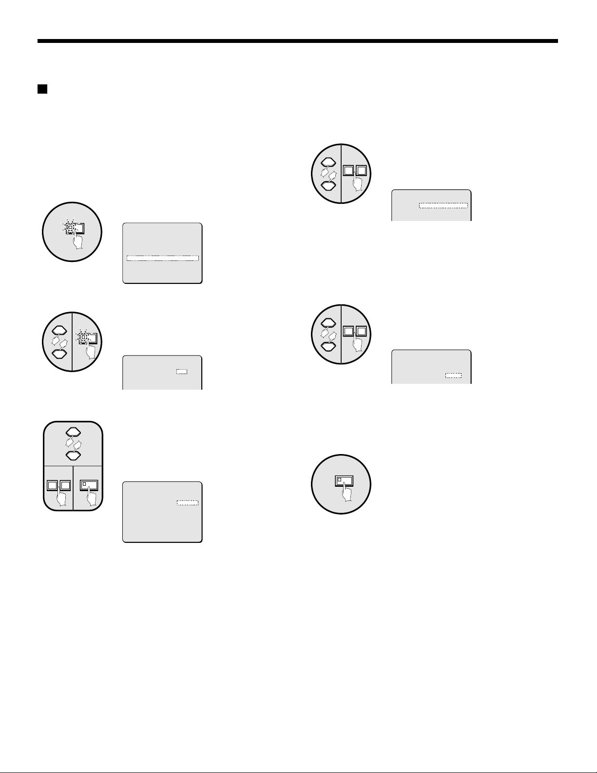
ALARM SET SETTINGS
ACTIVE REC setting (default setting: OFF)
The ACTIVE REC setting can be used to give priority to alarm images when recording images.
You can set the type of alarms to be recorded and the recording method for recording alarm images.
ALARM SET-4
Example: To record both external and
motion sensor alarm images in
MODE2 (See page 65.)
Press the MENU button.
1
MENU
2
NEXT
3
NEXT
+–
The MAIN MENU screen will be displayed.
(MAIN MENU)
1 LANGUAGE ¤
2 CLOCK SET ¤
3 DISPLAY SET ¤
4 VCR SET ¤
5 ALARM SET ¤
6 SECURITY SET ¤
7 CONTROL SET ¤
8 ALARM DATA ¤
(*:NEXT)
Use the cursor button to select
“ALARM SET” and then press the
NEXT button.
The ALARM SET screen will be displayed.
(ALARM SET)
ALARM OFF
ACTIVE REC. OFF
MOTION SENSOR OFF
VIDEO LOSS OFF
Use the cursor button to select
ACTIVE REC. “OFF”, use the
setting buttons to select “ON”, and
then press the NEXT button.
The ACTIVE REC. SET screen will be
displayed.
(ALARM SET)
ALARM OFF
ACTIVE REC. ON *
MOTION SENSOR OFF
VIDEO LOSS OFF
Use the cursor button to select AL.
4
REC. “EXT.”, and then press the
+–
setting buttons to select to “EXT.
OR M. SENSOR”.
(ACTIVE REC.SET)
AL.REC.EXT.OR M.SENSOR
REC.MODE MODE1
Display examples:
• EXT.: Only external alarms will be recorded.
• EXT. OR M.SENSOR: Both external alarms and motion
sensor alarms will be recorded.
• M.SENSOR: Only motion sensor alarms will be recorded.
5
Display examples:
Use the cursor button to select
REC. MODE “MODE1”, and then
+–
press the setting buttons to set to
“MODE2”.
(ACTIVE REC.SET)
AL.REC.EXT.OR M.SENSOR
REC.MODE MODE2
• MODE1: (See page 65.)
• MODE2: (See page 65.)
• ONLY: (See page 66.)
6
MENU
Press the MENU button.
When an external alarm occurs, the alarm
images will be recorded according to the
MODE2 settings.
ALARM SET-4
(*:NEXT)
Display examples:
• ON: Alarm images are recorded.
• OFF: Alarm images are not recorded.
Note:
If OFF has been selected as the ACTIVE REC. setting, the
following settings cannot be made.
Please note that if the ALARM SET setting DURATION is set
•
to NC, alarm images will continue to be recorded until the
alarm is canceled with the camera select button.
(See page 62.)
If an ALARM SET setting is set to OFF, the duration of active
•
alarm recording will be fixed at 10 seconds. RETRIGGER will
also be OFF. (See page 61.)
– 64 –
English

ALARM SET SETTINGS
Display examples:
• MODE1:
Recording alternates between images from the cameras where an alarm has occurred and images from all cameras that are
connected. If alarms have occurred at more than one camera, images from the cameras where an alarm has occurred and images
from all cameras are alternately recorded one image at a time.
• Recording pattern if an alarm occurs at camera 2
• Recording pattern if alarms occur at two or more cameras (e.g. cameras 2 and 4)
• MODE2:
Recording alternates between images from the cameras where an alarm has occurred and images from all cameras that are
connected. If alarms have occurred at more than one camera, one image from each the cameras where an alarm has occurred is
recorded first, and then one image from among all of the cameras connected is recorded.
• Recording pattern if an alarm occurs at camera 2
• Recording pattern if alarms occur at two or more cameras (e.g. cameras 2 and 4)
ALARM SET-5

ALARM SET SETTINGS
• ONLY:
Only images from the camera where the alarm is detected are recorded. If more than one alarm has been detected, the alarm
images are recorded alternately.
• Recording pattern if an alarm occurs at camera 2
• Recording pattern if alarms occur at two or more cameras (e.g. cameras 2 and 4)
ALARM SET-6

ALARM SET-7
ALARM SET SETTINGS
MOTION SENSOR setting
(default setting: OFF)
To display motion sensors on each camera image and make
settings for intruder detection. The motion sensors work as
shown below.
1 2 2
----------------
----------------
----------------
----------------
----------------
----AAAA--------
----------------
----------------
------------BBBB
---------------CAMERA NO.01 T-1 LEVEL:OFF MODE:A
3546
Motion sensor off status
1
When the cursor button is pressed, the cursor moves.
Sensor setting
2
When the setting buttons are pressed, the setting changes to
“A”, “B” or “–”.
Set to “A” or “B” in accordance with the desired sensor
detection position.
Camera display
3
When the camera select button is pressed, the camera
number changes. Use the camera select button to select
cameras that are set for motion sensor alarms.
Setting motion sensor operating times
4
Use timer settings to select specified time zones (T-1 to 4).
This will enable an alarm to be detected by motion sensors
with specified sensitivities only in the selected time zones
(See page 36).
Motion sensor sensitivity setting
5
This sets the sensor sensitivity.
•
1, 2, 3, 4 ... (the higher the number, the lower the
sensitivity), OFF
Motion sensor detection setting
6
• A: A motion sensor alarm is generated when a moving
object is detected at A.
• A AND B: When an object is detected touching both
sensors at point A and point B, a motion sensor alarm will
be triggered.
• A AND NB: With point A aligned on an important item
(object) and point B aligned on a non-moving object, a
motion sensor alarm will be triggered when the object at
point A is detected, without reacting to changes such as
the brightness of the whole screen.
• B TO A: A motion sensor alarm will be triggered if there is
any change in the movement of a subject passing from
point A to point B.
• C: A motion sensor alarm is generated when the whole
screen area changes uniformly. This results in a reaction
at times such as when the camera is sprayed with
something. (Sensor settings are not required.)
Example: To record images detected by the
motion sensor for the timer
setting duration
1
Set the TIMER setting in the CLOCK SET menu to
“ON”, make the settings for TIMER-A and
TIMER-B in the TIMER SET menu, and then select
MOTION SENSOR and close the CLOCK SET
screen.
Press the MENU button.
2
MENU
3
NEXT
4
NEXT
+–
5
5
The MAIN MENU screen will be displayed.
(MAIN MENU)
1 LANGUAGE ¤
2 CLOCK SET ¤
3 DISPLAY SET ¤
4 VCR SET ¤
5 ALARM SET ¤
6 SECURITY SET ¤
7 CONTROL SET ¤
8 ALARM DATA ¤
(*:NEXT)
Use the cursor button to select
“ALARM SET” and then press the
NEXT button.
The ALARM SET screen will be displayed.
(ALARM SET)
ALARM OFF
ACTIVE REC. OFF
MOTION SENSOR OFF
VIDEO LOSS OFF
Use the cursor button to select
MOTION SENSOR “OFF”, press the
setting buttons to change the
setting to “ON”, and then press the
NEXT button.
The motion sensor alarm setting screen
will be displayed.
(ALARM SET)
ALARM OFF
ACTIVE REC. OFF
MOTION SENSOR ON *
VIDEO LOSS OFF
(*:NEXT)
Press camera select button 5.
The image from camera 5 appears and T-1
flashes.
----------------
----------------
----------------
----------------
----------------
----------------
----------------
----------------
----------------
---------------CAMERA NO.05 T-1 LEVEL:OFF MODE:A
ALARM SET-7
English
– 67 –

ALARM SET SETTINGS
ALARM SET-8
6
+–
cursor to the middle of the screen,
and then press the setting buttons
so that “A” is displayed.
Use the cursor button to move the
Set so that “A” is displayed in the middle of
the screen.
------
----
--
CAMERA NO.05 T-1 LEVEL:OFF MODE:A
7
Use the cursor button to select “T-1”, and then
A
press the setting buttons to select “T-2”.
CAMERA NO.05 T-2 LEVEL:OFF MODE:A 2
8
Use the cursor button to select LEVEL “OFF”, and
then specify a sensitivity of “2” with the setting
buttons.
VIDEO LOSS setting
(default setting: OFF)
If the camera image disappears because of a sudden accident
or some other reason (so that image input stops), this sets
whether the image that appeared immediately before the signal
was lost is displayed as a still image or whether a test pattern is
displayed.
Example: To set a test pattern for the image
when there is a VIDEO LOSS
Press the MENU button, use the cursor button to
1
select “ALARM SET” and then press the NEXT
button.
The ALARM SET screen will be displayed.
2
Use the cursor button to select
VIDEO LOSS “OFF”, and then use
+–
the setting buttons to change to
“TEST”.
(ALARM SET)
ALARM OFF
ACTIVE REC. OFF
MOTION SENSOR OFF
VIDEO LOSS TEST
CAMERA NO.05 T-2 LEVEL:2 MODE:A 2
9
Use the cursor button to select “MODE”, and then
press the setting buttons to select “A”.
CAMERA NO.05 T-2 LEVEL:2 MODE:A 2
10
MENU
Press the MENU button.
This completes the setting. The display
•
will return to the camera image screen.
When an intruder comes into the middle
•
of the camera 5 image, an alarm will be
generated.
Display examples:
• OFF: When the video signal is lost, a blank screen is
displayed.
• FREEZE: The image displayed immediately before the video
signal was lost is displayed as a still image.
• TEST: When the video signal is lost, a test pattern is
displayed.
Note:
If no cameras are connected, “NO VIDEO” is displayed.
•
In this case, the video loss operation does not occur.
However, if the power is turned off when a video signal is
being input, the condition immediately before the video signal
was lost is detected and video loss operation occurs.
A still image or a test pattern is displayed during video loss
•
operation, but the recording device will record a test pattern
until the alarm is reset or the image returns to normal.
Even if a still image is set to be displayed during video loss
•
operation, a test pattern will appear if the screen is switched
or automatic switching display has been set.
3
MENU
Press the MENU button.
ALARM SET-8
– 68 –
English

ALARM SET-9
ALARM SET SETTINGS
Resetting an alarm
When images from the camera where the alarm was detected are appearing in a single-screen display
Press the camera select button for the camera that is being shown
4
When images from the camera where the alarm was detected are displayed in a multiple-screen
4
1
in the single-screen display.
The alarm will then be canceled.
Press the camera select button for the camera that is showing the
alarm.
The alarm images will appear in a single-screen display.
Press the camera select button again.
4
2
The alarm will then be canceled.
ALARM SET-9
English
– 69 –

SECURITY SET SETTINGS
(MAIN MENU)
1 LANGUAGE *
2 CLOCK SET *
3 DISPLAY SET *
4 VCR SET *
5 ALARM SET *
6 SECURITY SET *
7 CONTROL SET *
8 ALARM DATA *
(*:NEXT)
(SECURITY LOCK SET)
OPERATION
CODE 1111
LOCK OFF
SETUP
CODE 1111
LOCK OFF
All button operations are locked
Lock is applied for menu settings
You can set a security lock for the multiplexer to lock all button operations and menu operations in order to prevent mis-operations
from being carried out when camera images are being displayed or video images are being played back.
To set SECURITY LOCK for all operating buttons
This lets you set a 4-digit code number to use for locking menu screen settings.
Example: To register code numbers 1, 2, 3, 4
1
MENU
The MAIN MENU screen will be displayed.
(MAIN MENU)
1 LANGUAGE ¤
2 CLOCK SET ¤
3 DISPLAY SET ¤
4 VCR SET ¤
5 ALARM SET ¤
6 SECURITY SET ¤
7 CONTROL SET ¤
8 ALARM DATA ¤
(*:NEXT)
3
41
Press the MENU button.
Use the cursor button to select
OPERATION “CODE 1111”, and
then press camera select buttons 1,
2, 3 and 4.
(SEQURITY LOCK SET)
OPERATION
CODE 1111
LOCK OFF
(SEQURITY LOCK SET)
OPERATION
2
NEXT
Use the cursor button to select
“SECURITY SET” and then press
the NEXT button.
The SECURITY LOCK SET screen will be
CODE 1234
LOCK OFF
Note: Make sure that you do not forget the
code number.
displayed.
(SEQURITY LOCK SET)
OPERATION
CODE 1111
LOCK OFF
SETUP
CODE 1111
LOCK OFF
4
MENU
+–
Use the cursor button to select
OPERATION “LOCK OFF”, use the
setting buttons to select “ON”, and
then press the MENU button.
The display will return to the camera image
screen, and all button operations will be
locked.
(SEQURITY LOCK SET)
OPERATION
CODE 1234
LOCK OFF
(SEQURITY LOCK SET)
OPERATION
CODE 1234
LOCK ON
– 70 –
English

SECURITY SET SETTINGS
SECURITY CODE ----
SECURITY CODE ----
SECURITY CODE
¤¤¤¤
SECURITY CODE ----
SECURITY CODE ¤¤¤¤
SECURITY CODE ----
SECURITY CODE ----
SECURITY CODE ¤¤¤¤
SECURITY CODE ----
SECURITY CODE
¤¤¤¤
☞
To cancel the locking of all operating buttons
(OPERATION)
1
1
A buzzer will sound and the code number
request message will appear.
SECURITY CODE ----
SECURITY CODE ----
Note: If no action is taken, the code
number request message will
disappear after 10 seconds.
Press any single button.
2
SETUP setting
This lets you set a 4-digit code number to use for locking menu screen settings.
Example: To register code numbers 4, 3, 2, 1
Use the cursor button to select
1
SETUP “CODE 1111”, and then
press camera select buttons 4, 3, 2
and 1.
Note: Make sure that you do not forget the
14
code number.
SETUP
CODE 1111
LOCK OFF
☞
To cancel the locking of the MENU button
(SET UP)
1
1
MENU
Use the camera select buttons to
re-enter the code number (example:
1234) that was entered under
OPERATION “CODE”.
The buzzer will sound, the lock will be
canceled and the camera images will be
displayed.
SECURITY CODE
SECURITY CODE ¤¤¤¤
¤¤¤¤
Press the MENU button.
A buzzer will sound and a code number
request message will appear.
SECURITY CODE ----
SECURITY CODE ----
2
English
SETUP
CODE 4321
LOCK OFF
Note: If no action is taken, the code
number request message will
disappear after 10 seconds.
Use the cursor button to select
SETUP “LOCK OFF”, use the
2
1
setting buttons to select “ON”, and
then press the MENU button.
The menu screen settings are now locked.
MENU
+–
SETUP
CODE 4321
LOCK OFF
SETUP
CODE 4321
LOCK ON
Notes common to SECURITY LOCK:
If both the SETUP lock and the OPERATION lock are applied at the
•
same time, the code number request message will still appear when
the MENU button is pressed. If you enter the SETUP code number
at this time, both locks will be canceled, but if you enter the
OPERATION code number, only the OPERATION lock will be
canceled, and the SETUP lock will remain applied.
After the locks have been released and operations are enabled, if
•
you press and hold the
camera image is being viewed, the locking will be applied once more
with the menu in the mode that was set.
During playback, press the
•
Use the camera select buttons to
re-enter the code number (example:
4321) that was entered under
SETUP “CODE”.
The buzzer will sound and the lock will be
canceled.
SECURITY CODE
SECURITY CODE ¤¤¤¤
LIVE
VCR
¤¤¤¤
button for three seconds when a
button to engage the lock.
– 71 –

CONTROL SET SETTINGS
(MAIN MENU)
1 LANGUAGE *
2 CLOCK SET *
3 DISPLAY SET *
4 VCR SET *
5 ALARM SET *
6 SECURITY SET *
7 CONTROL SET *
8 ALARM DATA *
(*:NEXT)
(CONTROL SET)
DATA SPEED 19200
ALARM SEND ON
RS232C/RS485 RS232C
CAMERA CONTROL SANYO *
• Set a data transfer rate for serial communication.
• Set whether alarm information will be sent or not.
• Set whether RS-485 or RS-232C will be used for
serial communication.
Make dome-type camera settings to enable power
and signal control with a RS-485 dedicated coaxial
cable.
The following settings must be made if using the RS-232C connector or the RS-485 connector for serial communication between a
computer or a system controller and the multiplexer.
CONTROL SET settings
Settings for serial communication between the computer and
system controller using RS-232C connectors and RS-485
connectors.
1
MENU
2
NEXT
Press the MENU button.
The MAIN MENU screen will be displayed.
(MAIN MENU)
1 LANGUAGE ¤
2 CLOCK SET ¤
3 DISPLAY SET ¤
4 VCR SET ¤
5 ALARM SET ¤
6 SECURITY SET ¤
7 CONTROL SET ¤
8 ALARM DATA ¤
(*:NEXT)
Use the cursor button to select
“CONTROL SET” and then press
the NEXT button.
The CONTROL SET screen will be
displayed.
(CONTROL SET)
DATA SPEED 19200
ALARM SEND ON
RS232C/RS485 RS232C
4
5
Use the cursor button to select
DATA SPEED “19200”, and then
+–
press the setting buttons to set the
communication speed.
This sets the data communication speed
for serial communication.
(CONTROL SET)
DATA SPEED 19200
ALARM SEND ON
RS232C/RS485 RS232C
CAMERA CONTROL SANYO *
2400, 4800, 9600, 19200
Use the cursor button to select
ALARM SEND “ON”, and then press
+–
the setting buttons to select the
alarm data.
(CONTROL SET)
DATA SPEED 19200
ALARM SEND ON
RS232C/RS485 RS232C
CAMERA CONTROL SANYO *
Use the cursor button to select
3
+–
Display examples:
RS232C/RS485 “RS232C”, and then
press the setting buttons to select
“RS232C” or “RS485”
(CONTROL SET)
DATA SPEED 19200
ALARM SEND ON
RS232C/RS485 RS232C
Display examples:
• OFF: Alarm data is not transmitted.
• ON: Alarm data is transmitted.
Press the MENU button.
6
This completes the settings.
• When RS-232C is selected
Use a commercially available RS-232C cable for the
connection between the RS-232C connectors of this unit and
a personal computer.
• When RS-485 is selected
Use a modular cable or a twisted-pair cable for the
connections between the RS-485 control connectors of this
unit, the system controller and the digital video recorder.
– 72 –
English

CONTROL SET-1
CAMERA CONTROL setting
This describes the settings and methods of operation when
connecting a dome-type camera for which the power and signal
can be controlled through a coaxial cable to the camera video
input connector.
The two methods of operation are: direct control using the
control buttons on this unit and operation from the system
controller (using the RS-485 connector).
☞To control a dome-type camera with
this unit
1
LIVE
2
2
Note: Still image, zoom and automatic screen switching
operations are not available for signal-screen display on
the main monitor while the dome-type camera image is
being viewed.
3
To control the dome-type camera with the various
buttons of this unit
1 Cursor buttons: Enable pan and tilt operations
2 Setting buttons: Zoom in (+), zoom out (–)
3 Next screen button: Enables one-touch auto focus
2
4 Cursor button (→): Open iris
5 Setting button (+): Manual focus
English
While viewing, if you press and hold down the
camera select button for about two seconds, the
indicator will flash and the following camera
adjustments will be enabled.
Note: If you leave the indicator flashing, the ability
Cursor button (←): Close iris
Setting button (–): Manual focus
Press the LIVE button.
To display will return to the normal screen.
Press the camera select button
(example: 2) for the connected
dome-type camera.
The main monitor or spot monitor will
change to a single-screen display.
to make camera adjustments will be
canceled after about ten seconds. For
making adjustments, press the camera select
button once more.
1 4
3
2 5
☞To control the dome-type camera
from the system controller through
this unit.
Use the cursor button to select
1
NEXT
Display examples:
• SANYO: Select when a coaxial cable camera manufactured
by Sanyo is connected.
• OTHER: Select when a coaxial cable camera manufactured
by some other manufacturer is connected.
2
3
Note:
•
•
•
4
– 73 –
+–
Enter the RS-485 control address for a dome-type camera
that is connected to this unit.
When you press the setting button, OFF will change to 000
and you can then enter the address.
Addresses from 000 to 127 can be entered. The number will
be incremented by pressing the + setting button and
decremented by pressing the – setting button.
MENU
CAMERA CONTROL “SANYO”, and
then press the NEXT button.
The CAMERA CONTROL SET screen will
be displayed.
(CONTROL SET)
DATA SPEED 19200
ALARM SEND OFF
RS232C/RS485 RS232C
CAMERA CONTROL SANYO *
(*:NEXT)
Use the cursor buttons to select
“OFF” for the number of a
dome-type camera that is
connected (example: 01).
(CAMERA CONTROL SET)
IN IN
01:OFF 09:OFF
02:OFF 10:OFF
03:OFF 11:OFF
04:OFF 12:OFF
05:OFF 13:OFF
06:OFF 14:OFF
07:OFF 15:OFF
08:OFF 16:OFF
Press the setting button and use
the setting buttons once more to
enter the address of the camera
(example: 001).
(CAMERA CONTROL SET)
IN IN
01:001 09:OFF
02:OFF 10:OFF
03:OFF 11:OFF
04:OFF 12:OFF
05:OFF 13:OFF
06:OFF 14:OFF
07:OFF 15:OFF
08:OFF 16:OFF
Press the MENU button.
This completes the settings. Use the
control buttons in the system controller
“MULTIPLEXER” operating domain for
controlling the dome-type cameras.
CONTROL SET-1

ALARM DATA SETTINGS
Camera number
1
(MAIN MENU)
1 LANGUAGE *
2 CLOCK SET *
3 DISPLAY SET *
4 VCR SET *
5 ALARM SET *
6 SECURITY SET *
7 CONTROL SET *
8 ALARM DATA *
(*:NEXT)
1 2 3 4
(ALARM DATA) 1/ 1
CAM DATE TIME ITEM
1 1 06-08 11:45 E
2 2 06-08 10:30 S
3 3 06-08 08:30 V
(ALARM DATA screen)
Alarm data can be displayed on the screen in the form of an alarm list. This can be used for purposes such as checking the alarm
images that have been recorded by the recording device.
Note: To display alarm information in the alarm list, you need to make the required ALARM settings (see page 62) and set “ALARM
LIST” to “ON”.
Displaying the alarm data list
Press the MENU button.
1
MENU
The MAIN MENU screen will be displayed.
Shows the camera number where the alarm was
detected.
DATE
2
Shows the date that the alarm was detected.
TIME
3
Shows the time of day that the alarm was detected.
ITEM
4
E: Indicates that an external alarm was detected.
S: Indicates that a motion sensor alarm was detected.
V: Indicates that a video loss was detected.
(MAIN MENU)
1 LANGUAGE ¤
2 CLOCK SET ¤
3 DISPLAY SET ¤
4 VCR SET ¤
5 ALARM SET ¤
6 SECURITY SET ¤
7 CONTROL SET ¤
8 ALARM DATA ¤
(*:NEXT)
2
3
NEXT
NEXT
the NEXT button.
The ALARM DATA screen will be displayed.
To display the next page of the alarm list, press the NEXT button.
The next page of the alarm list will then be displayed.
Note: If the number of alarm entries reaches 100, the oldest entries will be
Use the cursor button to select “ALARM DATA” and then press
(ALARM DATA) 1/ 1
CAM DATE TIME ITEM
1 1 06-08 11:45 E
2 2 06-08 10:30 S
3 3 06-08 08:30 V
(ALARM DATA) 2/ 3
CAM DATE TIME ITEM
9 4 06-08 05:30 E
10 7 06-08 03:00 S
11 10 06-08 02:15 V
deleted and the newer entries will be displayed.
4
MENU
Press the MENU button.
– 74 –
English

INTERFACE SPECIFICATIONS
RS-232C
9-pin connector specifications
54321
9876
Data format
Mode Asynchronous
Character length 8 bits
Data transmit speed 2400, 4800, 9600, 19200 bps
Parity None
Stop bit 1
Communication protocol
Communication is carried out in units of 1 byte. After the computer transmits one byte of data, it waits for a
response from the multiplexer, and then transmits the next byte of data.
To start sending commands, an ON (F6) command is sent. The multiplexer will continue to receive
commands until an OFF (F7) command is sent to stop. The multiplexer sends an ACK (OA) each time it
receives a command.
See Table 4 - Command Table on page 79.
Pin No. Signal Operation Signal direction
1 ––
2 RXD Receive data Computer → Multiplexer
3 TXD Transmit data Multiplexer → Computer
4 –––
5 GND Ground –
6 –––
7 RTS Request to send Multiplexer → Computer
8 –––
9 –––
RS-485
RJ-11 connector specifications
Pin No. Pin A signals Pin B signals
123456
1 Spare Spare
2 Spare Spare
3 Signal B Signal A
4 Signal A Signal B
5 Spare Spare
6 Spare Spare
Data format
Mode Asynchronous
Character length 8 bits
Data transmit speed 2400, 4800, 9600, 19200 bps
Parity None
Stop bit 1
Communication protocol
A proprietary Sanyo protocol (SSP: Security Serial Protocol) is used. It is recommended that a special
controller be used. Contact the place of purchase for further details on obtaining a special controller.
English
– 75 –

INTERFACE SPECIFICATIONS
RS485 termination switch settings (RS485 TEAMINATE)
Termination setting
If several multiplexers are being connected together, termination settings must also be made.
Set the RS485 termination switch on the rear panel to ON, and set the termination switch of the last device in the series to ON.
•
Be sure to set the RS485 termination switches of all devices in between (devices other than the first and last in the series) to OFF.
•
System controller
RS485
POWER
GND
AAB
ON
12V DC IN
ADDRESS
B
123
1
0
OFF
TERMINATE
Time lapse VCR
ON
Termination switch
OFF
Note: If the termination settings are not correct, data will be
reflected by either end of the series and this will affect
the transmission of other data, so that the data that is
transmitted to each device will not be correct.

INTERFACE SPECIFICATIONS
Multiplexer data status command
STATUS SENSE (D7)
When this command is sent by the computer, the multiplexer
returns a 5-byte operating status code (Table 1).
RXD
TXD
D7
d1 d2 d3 d4 d5
STATUS SENSE (D7) bit allocation (Table 1)
The 4th and 5th bytes are spare.
1st byte
Bit Bit details
7 Indicates LIVE
and VCR
6 Indicates the
main monitor
5 001: 4-screen
display using 3
4 010: Multiple-screen
bits
3 Indicates the
display channels
2 0000: Channel 1
and menu
1 0001: Channel 2
numbers for each
0 0010: Channel 3
display on the
main monitor
using 4 bits
0: Live image mode
1: VCR playback mode
000: Single-screen
011: Plus screen
100: Menu selection
101: Series
111: Standby
(During single-screen)
0011: Channel 4
0100: Channel 5
0101: Channel 6
0110: Channel 7
0111: Channel 8
1000: Channel 9
1001: Channel 10*
1010: Channel 11*
1011: Channel 12*
1100: Channel 13*
1101: Channel 14*
1110: Channel 15*
1111: Channel 16*
(During 4-screen)
0000: 4-screen (1, 2, 3, 4)
0001: 4-screen (5, 6, 7, 8)
0010: 4-screen (9, 10*, 11*, 12*)
0011: 4-screen (13*, 14*, 15*, 16*)
(For multiple-screen)
0000: Single-screen
1000: 9-screen
1111: 16-screen*
(For plus screen)
0000: Channel 1
0001: Channel 2
0010: Channel 3
0011: Channel 4
0100: Channel 5
0101: Channel 6
0110: Channel 7
0111: Channel 8
1000: Channel 9
1001: Channel 10*
1010: Channel 11*
1011: Channel 12*
1100: Channel 13*
1101: Channel 14*
1110: Channel 15*
1111: Channel 16*
Bit Bit details
3 Indicates the
display channels
2 0000: MAIN
and menu
1 0001: SUB 1
numbers for each
0 0010: SUB 2
display on the
main monitor
using 4 bits
(For serial connection)
0011: SUB 3
(Menu selection)
0001: Menu 1 MAIN MENU settings
0010: Menu 2 LANGUAGE settings
0011: Menu 3 CLOCK SET settings
0100: Menu 4 DISPLAY SET settings
0101: Menu 5 VCR SET settings
0110: Menu 6 ALARM SET settings
0111: Menu 7 SECURITY SET
settings
1000: Menu 8 CONTROL SET settings
1001: Menu 9 ALARM DATA settings
2nd byte
Bit Bit details
7 Indicates EXIT
and ALARM
6 Indicates VIDEO
LOSS
5 Indicates
SENSOR
4 Spare 0
3 Indicates the
main monitor
2 0001: Automatic switching display
display status
1 0010: Zoom display
using 4 bits
0 0011: Still image
1: EXIT & ALARM ON
1: VIDEO LOSS ON
1: SENSOR ON
0000: Normal display
0100: Zoomed still image
0101: Still image zoomed
0110: Zoom position setting
0111: Still image zoom position setting
3rd byte
Bit Bit details
7 Indicates the
currently-
6 01: Spot monitor 2
operating spot
monitor using 2
bits
5 Spot monitor
operation
4 Spot monitor
operation
3 Indicates the
camera number
2 0001: Channel 2
for currently-
1 0010: Channel 3
operating spot
0 0011: Channel 4
monitor using 4
bits
Indicates the spot
monitor 1 camera
number when the
main monitor is
operating
*: Command for MPX-CD163 only
00: Spot monitor 1
10: Spot monitor 3
11: Spot monitor 4
1: Spot monitor operating
0: Single-screen
1: Automatic switching display
0000: Channel 1
0100: Channel 5
0101: Channel 6
0110: Channel 7
0111: Channel 8
1000: Channel 9
1001: Channel 10*
1010: Channel 11*
1011: Channel 12*
1100: Channel 13*
1101: Channel 14*
1110: Channel 15*
1111: Channel 16*
English
– 77 –

INTERFACE SPECIFICATIONS
4th byte
Bit Bit details
7 Indicates the
model number
6 0001: X-CD163 series
using 1 bit.
5
4
3 Spare
2 Spot monitor
operation
1 Indicates the
number of spot
0 01: 2
monitors using 2
bits
ALARM STATUS SENSE (D5)
Returns the multiplexer external alarm status (Table 2) using 6
bytes
RXD
D5
TXD
ALARM STATUS SENSE (D5) bit allocation (Table 2)
1st byte
Bit
7 ALARM 8 ON
6 ALARM 7 ON
5 ALARM 6 ON
4 ALARM 5 ON
3 ALARM 4 ON
2 ALARM 3 ON
1 ALARM 2 ON
0 ALARM 1 ON
3rd byte
Bit
7 SENSOR 8 ON
6 SENSOR 7 ON
5 SENSOR 6 ON
4 SENSOR 5 ON
3 SENSOR 4 ON
2 SENSOR 3 ON
1 SENSOR 2 ON
0 SENSOR 1 ON
0000: Older series (CD16, CD162)
1: Spot monitor operating
00: 1
10: 3
11: 4
d1 d2 d3 d4 d5 d6
2nd byte
Bit
7 ALARM 16 ON*
6 ALARM 15 ON*
5 ALARM 14 ON*
4 ALARM 13 ON*
3 ALARM 12 ON*
2 ALARM 11 ON*
1 ALARM 10 ON*
0 ALARM 9 ON*
4th byte
Bit
7 SENSOR 16 ON*
6 SENSOR 15 ON*
5 SENSOR 14 ON*
4 SENSOR 13 ON*
3 SENSOR 12 ON*
2 SENSOR 11 ON*
1 SENSOR 10 ON*
0 SENSOR 9 ON*
Multiplexer commands
ACK (0A)
Returned when the multiplexer receives a command.
NAK (0B)
Returned when the multiplexer does not receive a command.
ALARM (BF)
When there is alarm input, an ALARM command is sent as a
header, and after this the alarm data (Table 3) is sent using 1
byte.
Alarm data (Table 3)
Bit Bit details
7 Indicates the type of alarm
using 2 bits
6 01: External
5 Spare 0
4 Spare 0
3 Indicates the camera
number using 4 bits
2 0001: Channel 2
1 0010: Channel 3
0 0011: Channel 4
*: Command for MPX-CD163 only
00: No alarm input
10: Video loss
11: Motion sensor alarm
0000: Channel 1
0100: Channel 5
0101: Channel 6
0110: Channel 7
0111: Channel 8
1000: Channel 9
1001: Channel 10*
1010: Channel 11*
1011: Channel 12*
1100: Channel 13*
1101: Channel 14*
1110: Channel 15*
1111: Channel 16*
5th byte
Bit
7 VIDEO LOSS 8 ON
6 VIDEO LOSS 7 ON
5 VIDEO LOSS 6 ON
4 VIDEO LOSS 5 ON
3 VIDEO LOSS 4 ON
2 VIDEO LOSS 3 ON
1 VIDEO LOSS 2 ON
0 VIDEO LOSS 1 ON
*: Command for MPX-CD163 only
6th byte
Bit
7 VIDEO LOSS 16 ON*
6 VIDEO LOSS 15 ON*
5 VIDEO LOSS 14 ON*
4 VIDEO LOSS 13 ON*
3 VIDEO LOSS 12 ON*
2 VIDEO LOSS 11 ON*
1 VIDEO LOSS 10 ON*
0 VIDEO LOSS 9 ON*
– 78 –
English

INTERFACE SPECIFICATIONS
Command Table (Table 4)
The following table shows all of the commands that can be processed by the multiplexer.
If a command sent does not correspond to a multiplexer function, the command is received but no operation is carried out.
01234567
0 0
1 1
2 2
3 3 43
4 4 12MENU
5 5 + NEXT
6 6 – EXIT
7 7
8 8
9 9
A ACK
B NAK
C GROUP SET** POWER ON
D GROUP CHECK** POWER OFF
E GROUP CLEAR**
F
SECURITY
LOCK ON
SECURILY
LOCK OFF
89ABCDE F
0 LIVE FULL 1 CHECK ADJUST
1 VCR PB FULL 2 MENU RESET
2 MULTI FULL 3
3 QUAD FULL 4
4 PLUS FULL 5
5 ZOOM FULL 6
6 STILL FULL 7
7 SEQUENCE FULL 8 STATUS SENSE
8 SPOT MON FULL 9
9 ALARM MENU FULL 10*
A ALARM RESET FULL 11*
B FULL 12*
C FULL 13*
D FULL 14*
E FULL 15* RCV CHECK**
F FULL 16* ALARM
ALARM
STATUS SENSE
TRANSMISSION
START**
*: Command for MPX-CD163 only
**: Command for RS-485 only
English
– 79 –

SPECIFICATIONS
Signal format : Based on NTSC color signal standard
Camera signal input synchronization : Asynchronous
Camera video input connectors : VS/VBS, 1.0 Vp-p/75 Ω, BNC connector x 16 Control signal superimposed when camera operating
Camera video output connectors : Throughput of each input, 1.0 Vp-p/75 Ω, BNC connector x 16 (MPX-CD93: BNC connector x9)
VCR input connector
Composite input : VS/VBS, 1.0 Vp-p/75 Ω, BNC connector x 1
••••
S-Video input connector : Separate YC signals, DIN connector (S terminal) x 1
••••
Digital input connector : RJ-45 x 1
••••
VCR output connector
Composite output : VS/VBS, 1.0 Vp-p/75 Ω, BNC connector x 1
••••
S-Video output connector : Separate YC signals, DIN connector (S terminal) x 1
••••
Digital input connector : RJ-45 x 1
••••
Main monitor output connector
(MAIN MONITOR) : VS/VBS, 1.0 Vp-p/75 Ω, BNC connector x 1
S-Video output connector : Separate YC signals, DIN connector (S terminal) x 1
••••
Spot monitor output connectors
(SPOT MONITOR 1 - 4) : VS/VBS, 1.0 Vp-p/75 Ω, BNC connector x 4
Control connector
Remote control input (R1, R2) : 2-wire type with resistance-based identification system
••••
Alarm output (AL) : 5 V DC, 5.7 kΩ (Low output)
••••
Switch input (SW) : Low input, for input signal from SW OUT of timelapse VCR/real time VCR (as per this manufacturer
••••
Alarm input connectors : No voltage, make-contact switch input x 16 (Low input) (MPX-CD93: BNC connector x9)
Sensor alarm output connector : Alarm output x 16 (low output, normally open) (MPX-CD93: BNC connector x9)
RS-485 control connector : RJ-11 type: 2 connectors (A/B), Push-lock type: 3 connectors (A, B, Ground)
RS-232C connector :9-pin D-SUB
Automatic screen switching timing : Available in single-screen and quad mode, with interval selectable from 1 – 30 sec.
Monitor on-screen display : Title (up to 10 characters), date, time selectable
Menu settings
(MPX-CD93: BNC connector x9)
Y signal: 1.0 Vp-p/75 Ω, unbalanced, synchronous; C signal: 0.286 Vp-p/75 Ω, unbalanced
Y signal: 1.0 Vp-p/75 Ω, unbalanced, synchronous; C signal: 0.286 Vp-p/75 Ω, unbalanced
Camera live image or VCR playback image output: single-screen, automatic switching image,
multiple-screen
Y signal: 1.0 Vp-p/75 Ω, unbalanced, synchronous; C signal: 0.286 Vp-p/75 Ω, unbalanced
Camera live image: single-screen (Same image as main monitor selectable using menu/SPOT MONITOR
1 only)
specifications)

SANYO INDUSTRIAL
MULTIPLEXER WARRANTY
OBLIGATIONS
In order to obtain warranty service, the product must be delivered to and picked up from an Authorized Sanyo Service Center at the user’s expense,
unless specifically stated otherwise in this warranty. The names and addresses of Authorized Sanyo Service Centers may be obtained by calling the
toll-free number listed below.
For product operation, authorized service center referral, service assistance or problem resolution, call
CUSTOMER INFORMATION 1-800-421-5013
Weekdays 8:30 AM – 5:00 PM Pacific Time
For accessories and/or parts, call
PARTS ORDER INFORMATION 1-800-726-9662
Weekdays 8:30 AM – 5:00 PM Pacific Time
THIS WARRANTY IS VALID ONLY ON SANYO PRODUCTS PURCHASED OR RENTED IN THE UNITED STATES OF AMERICA, EXCLUDING ALL
U.S. TERRITORIES AND PROTECTORATES. THIS WARRANTY APPLIES ONLY TO THE ORIGINAL RETAIL PURCHASER OR END-USER. THE
ORIGINAL DATED BILL OF SALE, SALES SLIP OR RENTAL AGREEMENT MUST BE SUBMITTED TO THE AUTHORIZED SANYO SERVICE
CENTER AT THE TIME WARRANTY SERVICE IS REQUESTED.
Subject to the OBLIGATIONS above and EXCLUSIONS below, SANYO Fisher Company warrants this SANYO product against defects in materials
and workmanship for the periods specified below. SFC will repair or replace (at its option) the product and any of its parts which fail to conform to this
warranty. The warranty period commences on the date the product was first purchased or rented at retail.
LABOR PARTS
3 YEARS 3 YEARS
EXCLUSIONS
This warranty does not cover (A) the adjustment of customer-operated controls as explained in the appropriate model’s instruction manual, or (B) the
repair of any product whose serial number has been altered, defaced or removed.
This warranty shall not apply to the cabinet or cosmetic parts, batteries or routine maintenance.
This warranty does not apply to uncrating, setup, installation, removal of the product for repair or reinstallation of the product after repair.
This warranty does not apply to repairs or replacements necessitated by any cause beyond the control of SFC including, but not limited to, any
malfunction, defect or failure caused by or resulting from unauthorized service or parts, improper maintenance, operation contrary to furnished
instructions, shipping or transit accidents, modification or repair by the user, abuse, misuse, neglect, accident, incorrect power line voltage, fire, flood
or other Acts of God, or normal wear and tear.
The foregoing is in lieu of all other expressed warranties and SFC does not assume or authorize any party to assume for it any other obligation or
liability.
SFC DISCLAIMS ALL OTHER WARRANTIES EXPRESS OR IMPLIED, WITH REGARD TO THIS PRODUCT (INCLUDING THE WARRANTIES OF
MERCHANTABILITY AND FITNESS). IN NO EVENT SHALL SFC BE LIABLE FOR ANY SPECIAL, INCIDENTAL OR CONSEQUENTIAL DAMAGES
ARISING FROM THE OWNERSHIP OR USE OF THIS PRODUCT OR FOR ANY DELAY IN THE PERFORMANCE OF ITS OBLIGATIONS UNDER
THIS WARRANTY DUE TO CAUSES BEYOND ITS CONTROL. SFC’S LIABILITY FOR ANY AND ALL LOSSES AND DAMAGES RESULTING
FROM ANY CAUSE WHATSOEVER, ARISING OUT OF OR IN CONNECTION WITH THE SALE, USE OR OWNERSHIP OF THIS PRODUCT
INCLUDING WARRANTOR’S NEGLIGENCE, ALLEGED DAMAGED OR DEFECTIIVE GOODS, WHETHER SUCH DEFECTS ARE DISCOVERABLE
OR LATENT, SHALL IN NO EVENT EXCEED THE PURCHASE PRICE OF THE PRODUCT.
ATTENTION
For your protection in the event of theft or loss of this product, please fill in the information below for you own personal records.
Model No. _____________________________________________ Serial No. ______________________________________________
(Located on back or bottom side of unit.)
Date of Purchase _______________________________________ Purchase Price _________________________________________
Where Purchased _________________________________________________________________________________________________

Multiplexeur
Français F

PRÉCAUTIONS
ATTENTION
RISQUE DE CHOC
ÉLECTRIQUE NE PAS OUVRIR
ATTENTION:
ÉLECTRIQUE, NE RETIREZ PAS LE COUVERCLE (OU LE
COUVERCLE ARRIÈRE). AUCUNE PIÈCE RÉPARABLE PAR
L’UTILISATEUR À L’INTÉRIEUR. POUR TOUTE RÉPARATION
ADRESSEZ-VOUS À UN PERSONNEL QUALIFIÉ.
PRUDENCE:
POUR RÉDUIRE LE RISQUE DE CHOC
Pour éviter le risque d’incendie ou
de choc électrique, n’exposez pas cette unité à la
pluie ou à l’humidité.
ATTENTION:
Les changements ou modifications
non spécifiquement approuvés par Sanyo peuvent
annuler le droit de l’utilisateur de faire fonctionner cet
appareil.
La flèche en forme d’éclair, dans un triangle, avertit
l’utilisateur de la présence d’une “tension
dangereuse” non isolée à l’intérieur de l’appareil
qui peut être d’une force suffisante pour constituer
un risque de choc électrique aux personnes.
Le point d’exclamation dans un triangle avertit
l’utilisateur de la présence d’instructions
d’utilisation et d’entretien (réparation) importantes
dans la littérature accompagnant l’appareil.
Pour les utilisateurs au Canada
Cet appareil numérique est conforme à la
réglementation canadienne ICES-003.
ATTENTION
Danger d’explosion si la pile n’est pas remplacée
correctement.
Ne remplacer que par une pile du même type ou l’équivalent
tel que recommandé par le fabricant.
Mettre les piles usées au rebut en suivant les instructions du
fabricant.
Déclaration de conformité
Numéro de modèle : MPX-CD163/MPX-CD93
Marque de commerce : SANYO
Partie responsable : SANYO FISCHER COMPANY
Adresse : 21605 Plummer Street,
Chatsworth, california 91311
Téléphone : (818) 998-7322
• Cet appareil est conforme à la Partie 15 des
règlements du FCC. Le fonctionnement est sujet
aux deux conditions suivantes:
(1) Cet appareil ne doit pas causer d’interférences
nuisibles, et
(2) cet appareil doit accepter toute interférence
reçue, incluant toute interférence qui risque de
causer un mauvais fonctionnement.
Emplacement
Pour un fonctionnement sûr et un rendement optimal de votre
appareil, tenez compte des points suivants lors du choix d’un
emplacement pour son installation:
Protégez-le des rayons directs du soleil et tenez-le éloigné
•
des sources de chaleur intense.
Évitez les endroits poussiéreux ou humides.
•
Évitez les endroits ou la ventilation est insuffisante pour
•
assurer une bonne dissipation de la chaleur. Ne bloquez pas
les ouvertures pour la ventilation situées sur le dessus et en
dessous de l’appareil. Ne placez pas l’appareil sur un tapis
car cela obstrue les ouvertures pour la ventilation.
Installez toujours l’appareil en position horizontale.
•
Évitez les endroits soumis à de fortes vibrations.
•
Ne déplacez pas l’appareil d’un endroit froid à un endroit
•
chaud ou vice-versa.
Ne placez pas l’appareil directement sur un moniteur TV afin
•
d’éviter des problèmes d’interférences.
Protection contre les risques d’incendie
ou de choc électrique
Ne manipulez pas le cordon d’alimentation avec les mains
•
humides.
Pour débrancher le cordon d’alimentation de la prise de
•
courant, tenez-le par la fiche.
Si un liquide est renversé sur l’appareil, débranchez
•
immédiatement le cordon d’alimentation et faites inspecter
l’appareil par un centre de service agréé.
Ne placez pas d’objet directement sur l’appareil.
•
Français
ENTRETIEN
Cet appareil est un instrument de précision et si traité avec
soins, il donnera satisfaction pendant de longues années.
Cependant, en cas de problème, il est recommandé au
propriétaire de ne pas essayer d’y faire des réparations ou
d’ouvrir le boîtier. Les réparations doivent toujours être confiées
à votre revendeur ou à un Centre de service Sanyo autorisé.
– 1 –

TABLE DES MATIERES
CARACTÉRISTIQUES PRINCIPALES . . . . . . . . . . . . . . . . . . . . . . . . . . . . . . . . . . . . 4
ACCESSOIRES . . . . . . . . . . . . . . . . . . . . . . . . . . . . . . . . . . . . . . . . . . . . . . . . . . . . . . 4
NOM DE PIÈCE . . . . . . . . . . . . . . . . . . . . . . . . . . . . . . . . . . . . . . . . . . . . . . . . . . . . . . 5
Avant . . . . . . . . . . . . . . . . . . . . . . . . . . . . . . . . . . . . . . . . . . . . . . . . . . . . . . . . . . . .
Arrière . . . . . . . . . . . . . . . . . . . . . . . . . . . . . . . . . . . . . . . . . . . . . . . . . . . . . . . . . . .
BRANCHEMENTS. . . . . . . . . . . . . . . . . . . . . . . . . . . . . . . . . . . . . . . . . . . . . . . . . . . . 8
Branchements de base . . . . . . . . . . . . . . . . . . . . . . . . . . . . . . . . . . . . . . . . . . . . .
Branchement d’équipement vidéo pour une image de haute qualité
(S-VHS) . . . . . . . . . . . . . . . . . . . . . . . . . . . . . . . . . . . . . . . . . . . . . . . . . . . . . . . . . .
Branchements numériques. . . . . . . . . . . . . . . . . . . . . . . . . . . . . . . . . . . . . . . . . .
Branchements pour commande du système . . . . . . . . . . . . . . . . . . . . . . . . . . .
Commande d’ordinateur . . . . . . . . . . . . . . . . . . . . . . . . . . . . . . . . . . . . . . . . . . . .
5
7
8
8
9
11
11
Réglage de capteur d’alarme externe . . . . . . . . . . . . . . . . . . . . . . . . . . . . . . . . .
Utilisation comme panneau moniteur pendant une alarme de détecteur de
mouvement. . . . . . . . . . . . . . . . . . . . . . . . . . . . . . . . . . . . . . . . . . . . . . . . . . . . . . .
Branchement d’un circuit de commande à distance . . . . . . . . . . . . . . . . . . . . .
12
12
12
FONCTIONS DE SURVEILLANCE. . . . . . . . . . . . . . . . . . . . . . . . . . . . . . . . . . . . . . . 13
VISIONNEMENT D’IMAGES DE CAMÉRA . . . . . . . . . . . . . . . . . . . . . . . . . . . . . . . . 15
Visionnement d’une image en 1 écran. . . . . . . . . . . . . . . . . . . . . . . . . . . . . . . . .
Visionnement d’images en écrans multiples . . . . . . . . . . . . . . . . . . . . . . . . . . .
Visionnement d’images commutées automatiquement . . . . . . . . . . . . . . . . . . .
15
18
20
VISIONNEMENT D’IMAGES ENREGISTRÉES . . . . . . . . . . . . . . . . . . . . . . . . . . . . . 23
Lecture d’images enregistrées dans un affichage 1 écran . . . . . . . . . . . . . . . .
Lecture d’images en écrans multiples . . . . . . . . . . . . . . . . . . . . . . . . . . . . . . . . .
Lecture d’images commutées automatiquement . . . . . . . . . . . . . . . . . . . . . . . .
23
25
27
VISIONNEMENT SUR LE MONITEUR PONCTUEL . . . . . . . . . . . . . . . . . . . . . . . . . 29
Fonctions des boutons de moniteur ponctuel . . . . . . . . . . . . . . . . . . . . . . . . . .
Réglages du moniteur ponctuel . . . . . . . . . . . . . . . . . . . . . . . . . . . . . . . . . . . . . .
29
30
ORGANISATION ET OPÉRATIONS DES MENUS . . . . . . . . . . . . . . . . . . . . . . . . . . 31
Organigramme des menus . . . . . . . . . . . . . . . . . . . . . . . . . . . . . . . . . . . . . . . . . .
Opérations des menus . . . . . . . . . . . . . . . . . . . . . . . . . . . . . . . . . . . . . . . . . . . . .
31
32
RÉGLAGE DE LA LANGUE . . . . . . . . . . . . . . . . . . . . . . . . . . . . . . . . . . . . . . . . . . . . 33
Affichage de l’écran LANGUAGE . . . . . . . . . . . . . . . . . . . . . . . . . . . . . . . . . . . . .
33
RÉGLAGES DE L’HORLOGE. . . . . . . . . . . . . . . . . . . . . . . . . . . . . . . . . . . . . . . . . . . 34
Réglages de l’horloge . . . . . . . . . . . . . . . . . . . . . . . . . . . . . . . . . . . . . . . . . . . . . .
Réglages de PROGRAMMATEUR. . . . . . . . . . . . . . . . . . . . . . . . . . . . . . . . . . . . .
Réglage de HEURE ETE . . . . . . . . . . . . . . . . . . . . . . . . . . . . . . . . . . . . . . . . . . . .
– 2 –
35
36
38
Français

TABLE DES MATIERES
RÉGLAGES DE L’AFFICHAGE . . . . . . . . . . . . . . . . . . . . . . . . . . . . . . . . . . . . . . . . . 39
Réglage de TITRE. . . . . . . . . . . . . . . . . . . . . . . . . . . . . . . . . . . . . . . . . . . . . . . . . .
Réglage de MULTI ECRAN . . . . . . . . . . . . . . . . . . . . . . . . . . . . . . . . . . . . . . . . . .
Réglage de SEQUENCE. . . . . . . . . . . . . . . . . . . . . . . . . . . . . . . . . . . . . . . . . . . . .
Réglages de MASQUE . . . . . . . . . . . . . . . . . . . . . . . . . . . . . . . . . . . . . . . . . . . . . .
Réglage de PRINCIPAL → POINT1 . . . . . . . . . . . . . . . . . . . . . . . . . . . . . . . . . . . .
40
41
43
47
49
Réglages de BRANCHEMENT NUMERIQUE . . . . . . . . . . . . . . . . . . . . . . . . . . . .
Réglages du NIVEAU DE COULEUR . . . . . . . . . . . . . . . . . . . . . . . . . . . . . . . . . .
50
51
RÉGLAGES DE MAGNETOSCOPE . . . . . . . . . . . . . . . . . . . . . . . . . . . . . . . . . . . . . . 52
Réglages de MAGNETOSCOPE . . . . . . . . . . . . . . . . . . . . . . . . . . . . . . . . . . . . . .
Réglage de ENR.PROG . . . . . . . . . . . . . . . . . . . . . . . . . . . . . . . . . . . . . . . . . . . . .
53
56
RÉGLAGES DE ALARME. . . . . . . . . . . . . . . . . . . . . . . . . . . . . . . . . . . . . . . . . . . . . . 59
Réglages de ALARME . . . . . . . . . . . . . . . . . . . . . . . . . . . . . . . . . . . . . . . . . . . . . .
Réglage de AFFICHAGE ALARME . . . . . . . . . . . . . . . . . . . . . . . . . . . . . . . . . . . .
Réglage de MONITEUR PONCTUEL. . . . . . . . . . . . . . . . . . . . . . . . . . . . . . . . . . .
Réglage de ENR.ACTIF . . . . . . . . . . . . . . . . . . . . . . . . . . . . . . . . . . . . . . . . . . . . .
Réglage de DETEC. MOUV.. . . . . . . . . . . . . . . . . . . . . . . . . . . . . . . . . . . . . . . . . .
Réglage de DETECTEUR VIDEO. . . . . . . . . . . . . . . . . . . . . . . . . . . . . . . . . . . . . .
Réinitialisation d’une alarme . . . . . . . . . . . . . . . . . . . . . . . . . . . . . . . . . . . . . . . .
61
63
63
64
67
68
69
RÉGLAGES DE SECURITE . . . . . . . . . . . . . . . . . . . . . . . . . . . . . . . . . . . . . . . . . . . . 70
Pour régler le verrou de sécurité pour tous les boutons d’opérations. . . . . . .
Réglage de REGLAGE . . . . . . . . . . . . . . . . . . . . . . . . . . . . . . . . . . . . . . . . . . . . . .
70
71
RÉGLAGES DE COMMANDE . . . . . . . . . . . . . . . . . . . . . . . . . . . . . . . . . . . . . . . . . . 72
Réglages de COMMANDE . . . . . . . . . . . . . . . . . . . . . . . . . . . . . . . . . . . . . . . . . . .
Réglage de COMMANDE CAMERA. . . . . . . . . . . . . . . . . . . . . . . . . . . . . . . . . . . .
72
73
Français
RÉGLAGES DE DONNEES ALARME . . . . . . . . . . . . . . . . . . . . . . . . . . . . . . . . . . . . 74
Affichage de la liste de données d’alarmes. . . . . . . . . . . . . . . . . . . . . . . . . . . . .
74
SPÉCIFICATIONS D’INTERFACE . . . . . . . . . . . . . . . . . . . . . . . . . . . . . . . . . . . . . . . 75
SPÉCIFICATIONS . . . . . . . . . . . . . . . . . . . . . . . . . . . . . . . . . . . . . . . . . . . . . . . . . . . . 80
– 3 –

CARACTÉRISTIQUES
PRINCIPALES
Ce multiplexeur peut afficher les images qui sont enregistrées par une
caméra dans un écran divisé (16, 9, 4), et il peut aussi afficher les
images qui ont déjà été enregistrées, dans un écran divisé.
Le modèle MPX-CD93 est capable d’affichages en écran divisé de 4
écrans ou de 9 écrans uniquement.
•
Commutation à grande vitesse pour chaque champ à la vitesse
maximum
•
L’affichage en 1 écran, 4 écrans, 9 écrans et 16 écrans, les images
de caméra et les images de lecture vidéo peuvent être affichées
dans le coin inférieur droit de l’écran et la commutation automatique
est également possible.
•
Des multiplexeurs multiples peuvent être connectés ensemble pour
créer un système étendu pour la surveillance centralisée.
•
L’affichage de 1 écran peut être sélectionné pendant la surveillance
ponctuelle et l’écran d’alarme peut être affiché quand une alarme se
produit.
•
Le réglage du programmateur permet aux réglages suivants d’être
faits pour chaque caméra.
L’enregistrement programmé permet que les images d’une
–
caméra spécifique soient enregistrées pendant quatre zones
horaires quotidiennes différentes.
Commutation automatique des images de la caméra sélectionnée
–
par la période du programmateur
Réglage de la vitesse de commutation automatique de l’écran
–
pour chaque caméra pour quatre zones horaires quotidiennes
différentes.
•
Une fonction de masque de moniteur cache les images pour des
caméras spécifiques avec un motif gris de sorte qu’elles ne puissent
pas être surveillées.
•
La détection de mouvement par capteur est possible à chaque
caméra. Les objets mobiles peuvent être accordés une priorité à
l’enregistrement et l’exécution d’alarme est possible.
•
Lorsqu’une perte de signal est détectée, l’image de l’écran du
moniteur peut être remplacée par un motif de test ou une image fixe,
même si l’image de la caméra a été perdue en raison de
l’interruption.
•
Les caméras qui peuvent être commandées par l’intermédiaire de
câbles coaxiaux peuvent être branchées afin de permettre la
commande de ces caméras à partir du multiplexeur.
•
La commande par ordinateur par l’intermédiaire d’une interface
RS-232C est possible.
•
Le branchement à un contrôleur de système (vendu séparément) est
possible à l’aide d’une interface RS-485 (RJ-11).
•
Équipé de quatre sorties de moniteur ponctuel et de connecteurs
d’entrée et de sortie de signal S-Vidéo.
•
Les écrans de menu permettent l’affichage de jusqu’à 100 éléments
d’enregistrement d’alarme.
•
Le branchement à un équipement numérique tel qu’un enregistreur
vidéo numérique (Digital video recorder) (vendu séparément) est
possible à l’aide des connecteurs numériques.
ACCESSOIRES
Attache pour cordon
Cordon d’alimentation x1
d’alimentation x1
– 4 –
Français

NOM DE PIÈCE
Avant
(MPX-CD163)
Indicateur d’alimentation (POWER)
1
S’allume lorsque la fiche du cordon d’alimentation est insérée dans
une prise de courant secteur.
Indicateurs de moniteur ponctuel
2
Lorsque la surveillance ponctuelle a été réglée, l’indicateur du
moniteur spécifié s’allume. (Référez-vous à la page 29.)
Boutons et indicateurs de sélection de caméra
3
Lorsqu’une caméra est branchée à un des connecteurs d’entrée
vidéo de caméra (CAMERA IN) à l’arrière du multiplexeur et que le
bouton correspondant est pressé, l’indicateur s’allume et les
images de cette caméra sont affichées.
(Indicateurs)
•
Pendant la surveillance en écran divisé, les indicateurs pour
toutes les caméras affichées dans l’écran divisé s’allument.
•
Quand il y a une entrée d’alarme, l’indicateur de la caméra où
l’alarme est entrée clignote.
•
Lorsque l’opération de surveillance ponctuelle a été réglée,
l’indicateur du moniteur spécifié s’allume.
Bouton de moniteur ponctuel (SPOT MON.)
4
Ce bouton est utilisé pour régler la surveillance ponctuelle.
(Référez-vous à la page 29.)
Bouton et indicateur d’affichage multiple (MULTI)
5
Ce bouton vous permet de commuter l’affichage à l’affichage 16
écrans ou à l’affichage 9 écrans pendant que la surveillance est
faite en utilisant l’affichage 1 écran ou l’affichage 4 écrans.
Lorsque le bouton MULTI est pressé, l’affichage 9 écrans ou 16
écrans apparaît, puis l’affichage d’écran divisé change à chaque
fois que le bouton est pressé de nouveau.
L’indicateur s’allume, mais s’éteint lorsqu’une autre opération de
commutation d’écran est exécutée
•
Les positions de l’affichage d’écran divisé peuvent être
réarrangées à l’aide de l’écran de menu.
(Référez-vous à la page 41.)
•
Pour le modèle MPX-CD93, un affichage 9 écrans apparaît.
L’affichage 16 écrans n’est pas disponible.
Bouton et indicateur d’affichage 4 écrans (QUAD)
6
Ce bouton vous permet de commuter l’affichage à l’affichage 4
écrans pendant que la surveillance est faite en utilisant l’affichage
16 écrans ou l’affichage 9 écrans.
Lorsque le bouton QUAD est pressé, l’écran commute à l’affichage
4 écrans, et l’affichage 4 écrans change (1 – 4,
5 – 8, 9 – 12, 13 – 16) à chaque fois que le bouton QUAD est
pressé de nouveau. L’indicateur s’allume suivant l’affichage 4
écrans.
•
Pour le modèle MPX-CD93, l’affichage 4 écrans change à
chaque fois que le bouton QUAD est pressé (1 – 4, 5 – 8,
9 – 3)
•
Les positions de l’affichage d’écran divis

NOM DE PIÈCE
Bouton et indicateur de lecture vidéo (VCR)
9
Appuyez sur ce bouton pour faire la lecture d’images enregistrées.
L’indicateur s’allumera et les images de lecture vidéo apparaîtront
sur le moniteur.
Bouton et indicateur de commutation automatique de la
F
caméra (SEQUENCE)
Ce bouton est utilisé pour changer automatiquement l’image de la
caméra apparaissant dans l’affichage 1 écran, 4 écrans ou
l’affichage quart d’écran (écran plus).
Lorsque le bouton SEQUENCE est pressé, l’indicateur clignote et
l’écran change automatiquement. L’indicateur de caméra change
également suivant les images sur l’écran.
Bouton et indicateur d’image fixe (STILL)
G
Si ce bouton est pressé pendant que la surveillance est faite en
utilisant l’affichage 1 écran, l’indicateur clignotera et l’image sera
gelée. Si le bouton est pressé une fois de plus, l’image revient à la
normale.
Bouton et indicateur de zoom électronique (ZOOM)
H
Si la surveillance est faite en utilisant l’affichage 1 écran, l’image
peut être agrandie par un facteur de 2x. Lorsque ce bouton est
pressé, l’indicateur clignotera et l’écran du zoom 2x sera affiché.
Bouton et indicateur de menu (MENU)
I
Ce bouton est utilisé pour afficher l’écran de menu.
Bouton et indicateur d’écran suivant (NEXT)
J
•
Si ce bouton est pressé pendant qu’un écran de menu (écran de
réglage) est affiché, un sous-menu de réglage est affiché.
•
Si une caméra qui peut être commandée par l’intermédiaire d’un
câble coaxial (telle qu’une caméra de type dôme) est branchée,
ce bouton peut être utilisé pour l’ajustement de la mise au point
une touche. La lecture d’images enregistrées provenant
d’enregistreurs vidéo numériques multiples est effectuée en
sélectionnant les images sur les enregistreurs vidéo numériques.
Bouton et indicateur d’annulation/affichage (BACK)
K
•
Si ce bouton est pressé pendant qu’un écran de sous-menu est
affiché, l’écran revient à l’écran précédent.
•
Si ce bouton est pressé pendant l’affichage des images de
caméra, les affichages à l’écran (tels que les titres) peuvent être
affichés ou effacés.
Boutons de réglage (+, –)
L
•
Ces boutons sont utilisés pour changer les valeurs des réglages
dans les écrans de menu (écrans de réglage).
•
Si une caméra à câble coaxial (telle qu’une caméra de type
dôme) est branchée, ces boutons peuvent être utilisés pour
effectuer les opérations de zoom.
De plus, si ces boutons sont pressés après avoir appuyé sur un
bouton de sélection de caméra, l’ajustement manuel de la mise
au point est possible. Ils peuvent également être utilisés pour
ajuster la vitesse de lecture lorsque des images enregistrées
provenant d’un enregistreur vidéo numérique sont lues.
Boutons de curseur
M
•
Ces boutons peuvent être utilisés pour sélectionner les articles
pendant qu’un écran de menu (écran de réglage) est affiché.
•
Si une caméra qui peut être commandée par l’intermédiaire d’un
câble coaxial (telle qu’une caméra de type dôme) est branchée,
ces boutons peuvent être utilisés pour effectuer les opérations
de panoramique et d’inclinaison.
•
Ils peuvent également être utilisés pour les opérations de
lecture, d’arrêt, de pause et de lecture inverse lorsque des
images enregistrées provenant d’un enregistreur vidéo
numérique sont lues.
Bouton de réinitialisation de menu/réglage d’horloge (MENU
N
RESET)
Si ce bouton est pressé pendant qu’un écran de menu (écran de
réglage) est affiché, les réglages de l’écran de menu affiché sont
réinitialisés à leurs valeurs par défaut.
Si ce bouton est pressé tout en surveillant les images de caméra,
l’horloge est ajustée et, les minutes et les secondes sont remises à 00.

NOM DE PIÈCE
Arrière
123
IN
OUT
VCR
OUT
IN
S-VIDEO
4 5 6 7 9 101112131415168
MAIN
VCR
MONITOR
IN
MAIN
MONITOR
CAMERA
SPOT MONITOR
2
1OUT
34 A
DIGITAL
OUT
DO NOT CONNECT TO PHONE LINE
RS485
S
W
RS485
ALARM OUT REMOTE
A B C C R1 R2 C C
CONTROL
AC IN
IN
ALARM IN
C
12345678910IN11 12 13 14 15 16
SENSOR
ALARM OUT
RS485
B
RS232C
TERMINATE
C
ON
ALL
RESET
OFF

BRANCHEMENTS
Assurez-vous de bien lire le manuel d’instructions de chaque appareil branché au multiplexeur.
Si les branchements sont incorrects, cela peut causer de la fumée ou un mauvais fonctionnement.
Coupez l’alimentation de tous les composants avant de les brancher.
Branchements de base (Modèle MPX-CD163)
Neuf caméras peuvent être connectées au modèle MPX-CD93.
Branchement d’équipement vidéo pour une image de haute qualité (S-VHS)

BRANCHEMENTS
Branchements numériques
A Branchement numérique de quatre multiplexeurs
Jusqu’à quatre de ces unités peuvent être connectées pour la surveillance.
En connectant plusieurs unités, jusqu’à 64 caméras peuvent être visionnées sur un moniteur principal. De plus, en branchant un enregistreur à chaque
multiplexeur, la lecture des images enregistrées peut être visionnée sur le moniteur principal.
* Pour le modèle MPX-CD93, le nombre total de caméras qui peuvent être visionnées sur un moniteur est de 36, soit neuf pour chaque unité.
Utilisez des câbles CAT-5 RS485 de type droit (vendus séparément) pour brancher les connecteurs DIGITAL IN aux connecteurs de sortie numérique
d’autres appareils.
Utilisez des câbles de 3 m ou moins de longueur.
2
1
3
4
6
5
7
8
10
9
11
12
14
13
15
16
Remarque: (Unité principale et unités secondaires)
•
L’unité principale et les unités secondaires doivent être spécifiées. La distinction entre une unité principale et les unités secondaires permet à
l’unité principale d’afficher les images de caméra d’une unité secondaire sur le moniteur. (Référez-vous à la page 50.)
•
Étant donné qu’aucun signal vidéo n’est émis au connecteur de sortie de moniteur principal sur le panneau arrière d’une unité secondaire, si un
moniteur est branché l’écran sera noir.
•
Si ces branchements ont été faits, un enregistreur vidéo numérique ne peut pas être connecté numériquement.

BRANCHEMENTS
B Branchement numérique du multiplexeur et d’un enregistreur vidéo numérique
Cet appareil et un enregistreur vidéo numérique peuvent être connectés numériquement pour une lecture à haute résolution des images enregistrées.
Utilisez des câbles CAT-5 RS485 de type droit (vendus séparément) pour brancher les connecteurs DIGITAL IN aux connecteurs de sortie numérique
d’autres appareils.
Utilisez des câbles de 3 m ou moins de longueur.
2
1
3
4
6
5
7
8
10
9
11
12
14
13
15
16

BRANCHEMENTS
A
Branchements pour commande du système
Utilisez le connecteur RS-485 ou le connecteur CONTROL pour brancher un contrôleur de système au multiplexeur. Après avoir branché le contrôleur
de système, vous devrez effectuer les réglages indiqués dans le menu COMMANDE. (Référez-vous à la page 72.)
À l’aide du connecteur RS-485 (RJ-11)
A
Branchez les câbles modulaires (vendus séparément) aux connecteurs
de commande RS-485 à l’arrière du multiplexeur.
Si un câble de type droit est utilisé
•
Branchez le connecteur A au connecteur A et le connecteur B au
connecteur B.
Si un câble de type croisé est utilisé
•
Branchez le connecteur A au connecteur B et le connecteur B au
connecteur A.
Type droit Type croisé
Pièces de rechange
1
Pièces de rechange
2
61616116
3
4
Pièces de rechange
5
Pièces de rechange
6
À l’aide du connecteur CONTROL (A/B)
B
1
2
3
4
5
6
Pièces de rechange
1
Pièces de rechange
2
3
4
5
Pièces de rechange
6
Pièces de rechange
1
2
3
4
5
6
Branchez un câble à paires torsadées (vendu séparément) aux
connecteurs A, B et C (masse) du connecteur CONTROL à l’arrière du
multiplexeur. Branchez le signal A au signal A et le signal B au signal B.
À l'autre
connecteur A
Câble de type droit Câble de type croisé
Poussez pour faire entrer le câble.
À l'autre
connecteur
Câble à paires torsadées
Masse
Au signal B
Au signal A
Commande d’ordinateur
Lors du branchement du multiplexeur à un ordinateur (vendu séparément), utilisez un câble D-Sub de 9 broches (vendu séparément) pour brancher le
connecteur RS-232C à l’ordinateur. Après avoir fait le branchement, vous devrez effectuer les réglages indiqués dans le menu COMMANDE.
(Référez-vous à la page 72.)
Ordinateur
A B
Français
– 11 –

BRANCHEMENTS
Réglage de capteur d’alarme externe
Afin de faire un fonctionner un capteur d’alarme externe, un
commutateur externe doit être branché au connecteur ALARM IN.
Quand un intrus actionne le commutateur externe (comme par
l’ouverture d’une porte), un signal d’alarme est reçu et une alarme peut
sonner.
Le modèle MPX-CD93 utilise les connecteurs indiqués par *.
Utilisation comme panneau moniteur
pendant une alarme de détecteur de
mouvement
Lorsque le détecteur de mouvement intégré au multiplexeur répond à
une alarme, il envoie un signal d’alarme au connecteur SENSOR
ALARM OUT. Si un circuit de commutation tel qu’un indicateur
d’avertissement est branché à ce connecteur, l’indicateur
d’avertissement s’allumera lorsqu’il y a une réponse du détecteur de
mouvement. Si l’indicateur d’avertissement est fixé sur un diagramme
de disposition pour un endroit comme une usine, l’emplacement de la
caméra peut être facilement déterminé en cas d’urgence. Le connecteur
est toujours ouvert. La broche correspondant au numéro de la caméra
qui génère une réponse de capteur commute à BAS.

FONCTIONS DE SURVEILLANCE
Ce qui suit est un sommaire des opérations qui peuvent être effectuées tout en surveillant les images de caméra. Référez-vous aux numéros de page
correspondants pour des explications plus détaillées.
Visionnement d’images de caméra
(référez-vous à la page 15.)
Les opérations suivantes peuvent être effectuées tout en surveillant les images de caméra et en faisant la lecture d’images enregistrées.
Visionnement d’images enregistrées
(référez-vous à la page 23.)
◆ Visionnement d’une image en 1 écran (référez-vous à la page 15.)
ZOOM
4
1 écran
STILL
Zoom
Image fixe
◆ Visionnement d’images en écrans multiples (référez-vous à la page 18.)
PLUS
Affichage 9 écrans
MULTIMULTI
PLUS
QUAD
Affichage 4 écrans
Pour le modèle MPX-CD93, un affichage 9 écrans apparaît.
◆ Visionnement d’images commutées automatiquement (référez-vous à la page 20.)

FONCTIONS DE SURVEILLANCE
VIDEO LOSS
Fonction d’alarme
Les personnes suspectes peuvent être détectées pendant la surveillance à l’aide de la fonction de réglage d’alarme. (Référez-vous à la page 60.)
Capteur d'alarme externe
Alarme de capteur
(référez-vous à la
page 67.)
A A
A A
CAMERA 4
CAMERA 1
VIDEO LOSS
VIDEO LOSS
Alarme externe
(référez-vous à la page 12.)
Alarme de détection de perte de signal
(référez-vous à la page 68.)
Fonction d’enregistrement
Un appareil d’enregistrement vidéo peut être utilisé pour enregistrer les images de caméra et les images d’alarme saisies pendant la surveillance.
Magnétoscope
Moniteur
Moniteur
Magnétoscope
Moniteur
Fonction de programmateur
En utilisant la fonction de programmateur, une journée peut être divisée en quatre zones horaires différentes et chaque caméra peut être activée
séparément dans chaque zone horaire.
La commutation automatique de l’affichage et l’enregistrement de différentes images de caméra peuvent être spécifiés pour chaque zone horaire.
De plus, si des alarmes de capteur sont réglées, les intrus peuvent être détectés pendant ces zones horaires.
•
Réglage du programmateur (référez-vous à la page 36.)
•
Utilisation de la fonction de programmateur pour la commutation automatique de l’affichage (référez-vous à la page 45.)
•
Utilisation de la fonction de programmateur pour enregistrer des images (référez-vous à la page 58.)
•
Utilisation de la fonction de programmateur pour détecter des alarmes (référez-vous à la page 67.)
•
Utilisation de la fonction de temporisateur pour masquer l’image de caméra à l’aide d’un motif gris (référez-vous à la page 48.)

VISIONNEMENT D’IMAGES DE CAMÉRA
Visionnement d’une image en 1 écran
Appuyez sur le bouton LIVE.
LIVE
Réglage de l’image de la caméra à l’affichage 1 écran
2
Pause des images
L’image de caméra apparaît comme écran divisé.
Appuyez sur un bouton de sélection de caméra (exemple: 2).
L’image de la caméra 2 apparaît dans un affichage 1 écran.
1
STILL
2
STILL
Appuyez sur le bouton STILL.
L’image sera gelée.
Pour annuler l’image fixe, appuyez sur le bouton STILL de nouveau.
La pause sera annulée et les images normales seront affichées.
Remarque: Si vous appuyez sur le bouton ZOOM pendant que l’image est gelée,
l’image fixe sera agrandie. Pour retourner à l’image fixe initiale, appuyez
sur le bouton ZOOM de nouveau.
STILL STILLZOOM
Français
– 15 –

VISIONNEMENT D’IMAGES DE CAMÉRA
Agrandissement d’images
Appuyez sur le bouton ZOOM.
ZOOM
1
Les images seront agrandies.
Remarque: Si vous réglez un cadre de zoom, la zone de l’image à l’intérieur du cadre
de zoom sera agrandie. (Référez-vous à la page 17.)
Si vous appuyez sur le bouton de sélection de
caméra pendant un zoom, l’image sera plus facile
Image avec peu
de mouvement
à voir dû au mouvement du sujet. Les
changements suivants se produiront si vous
appuyez sur le bouton de sélection de caméra à
plusieurs reprises.
Une image avec peu de mouvement (une image
•
presque fixe)
Les grands sujets sont plus clairs et les sujets en
mouvement apparaissent légèrement flous.
Une image avec beaucoup de mouvement
•
(visionnement normal)
L’image d’un sujet en mouvement est plus claire et les
sujets avec peu de mouvement apparaissent légèrement
flous.
L’image agrandie est
un peu floue
Image avec beaucoup
de mouvement
L’image agrandie est
un peu floue
2
Le sujet est plus
clair
4
Le sujet est plus
clair
Pour retourner une image agrandie à l’affichage d’image normal,
ZOOM
appuyez sur le bouton ZOOM de nouveau.
Le zoom sera annulé et les images normales seront affichées.
2
– 16 –
Français

VISIONNEMENT D’IMAGES DE CAMÉRA
Exemple: Pour faire un zoom sur l’image de la caméra 2 et déplacer le cadre de zoom
Vous pouvez sélectionner la position de zoom au moyen du cadre de zoom qui apparaît sur l’écran. La position du cadre de zoom est initialement au
milieu de l’écran.
Appuyez sur le bouton de sélection de caméra 2.
2
1
ZOOM
2
2
3
L’image de la caméra 2 apparaîtra dans un affichage 1 écran.
Appuyez sur le bouton ZOOM.
Les images seront agrandies.
Maintenez le bouton de sélection de caméra 2 pendant environ 3
secondes ou plus.
Le zoom sera annulé et l’image normale apparaîtra, et le cadre de zoom (G) apparaîtra
sur l’écran.
Remarque: Si le cadre de zoom reste à l’écran pendant environ 10 secondes sans être
ajusté, l’écran reviendra à l’affichage du zoom.
Pour faire réapparaître le cadre de zoom, maintenez le bouton de sélection
de caméra 2 de nouveau pendant 3 secondes ou plus.
Appuyez sur le bouton de curseur pour déplacer le cadre de zoom à la
position que vous désirez agrandir.
4
Appuyez sur le bouton de sélection de caméra 2 de nouveau.
2
5
ZOOM
L’image dans le cadre de zoom sera agrandie.
Remarque: Si vous appuyez sur le bouton STILL pendant un zoom sur les images,
une image fixe agrandie sera affichée.
Pour retourner une image agrandie à l’affichage d’image normal,
appuyez sur le bouton ZOOM de nouveau.
Le zoom sera annulé et les images normales seront affichées.
6
Français
– 17 –
 Loading...