


Fisher MR850 User manual

Technical Documentation
Fisher & Paykel® MR 850
Respiratory Humidifier
Revision 5.0 5697.500 9036209
Because you care

K5697500IECIVZ.fm 10.05.06 |
All rights reserved. Copyright reserved. |
Contents
General
1 |
Symbols and Definitions |
3 |
2 |
Notes |
3 |
Function Description
1 |
MR 850 Respiratory Humidifier |
7 |
||
|
1.1 |
Humidifier Operation .............................................................................................................. |
7 |
|
|
1.2 |
Operating Modes .................................................................................................................... |
8 |
|
|
|
1.2.1 |
Stand-by mode ......................................................................................................... |
8 |
|
|
1.2.2 |
Intubated mode ........................................................................................................ |
8 |
|
|
1.2.3 |
Mask mode ............................................................................................................... |
8 |
|
1.3 |
Controls |
.................................................................................................................................. |
9 |
|
|
1.3.1 |
On/off button ............................................................................................................. |
9 |
|
|
1.3.2 |
Mode button ............................................................................................................. |
9 |
|
|
1.3.3 |
Mute button .............................................................................................................. |
9 |
|
1.4 |
Optical Indicators .................................................................................................................. |
10 |
|
|
|
1.4.1 |
Display .................................................................................................................... |
10 |
|
|
1.4.2 Humidity alarm (lung symbol) ................................................................................. |
10 |
|
|
|
1.4.3 |
Warning triangle alarm ........................................................................................... |
10 |
|
1.5 |
Setup Indicators (LEDs) ....................................................................................................... |
10 |
|
|
|
1.5.1 |
Temperature probes ............................................................................................... |
10 |
|
|
1.5.2 |
Heater wire adapter ................................................................................................ |
10 |
|
|
1.5.3 |
Temperature probe connectors .............................................................................. |
11 |
|
|
1.5.4 Humidification chamber temperature probe alarm with probe connector alarm ..... |
11 |
|
|
|
1.5.5 Airway temperature probe alarm with probe connector alarm ................................ |
11 |
|
|
|
1.5.6 |
Water out LED ........................................................................................................ |
11 |
|
1.6 |
Operational Alarms ............................................................................................................... |
11 |
|
|
|
1.6.1 Humidity alarm (lung symbol) ................................................................................. |
11 |
|
I

Contents
Annex
Parts catalog
Test List
All rights reserved. Copyright reserved. |
K5697500IECIVZ.fm 10.05.06 |
II

General
1

2

Fisher & Paykel MR 850 |
General |
|
|
1Symbols and Definitions
WARNING
A WARNING statement provides important information about a potentially hazardous situation which, if not avoided, could result in death or serious injury.
CAUTION
A CAUTION statement provides important information about a potentially hazardous situation which, if not avoided, may result in minor or moderate injury to the user or patient or in damage to the equipment or other property.
NOTE
A NOTE provides additional information intended to avoid inconvenience during operation.
Definitions according to German standard DIN 31051:
Inspection |
= examination of actual condition |
|
Maintenance |
= measures to maintain specified condition |
|
Repair |
= |
measures to restore specified condition |
Servicing |
= |
inspection, maintenance, and repair |
2Notes
Technical Documentation.fm |
|
Released Printed on 10.05.06 General_ |
reserved. Copyright reserved. |
Version 3.0_ |
All rights |
This Technical Documentation conforms to the IEC 60601-1 standard.
Read each step in every procedure thoroughly before beginning any test. Always use the proper tools and specified test equipment. If you deviate from the instructions and/or recommendations in this Technical Documentation, the equipment may operate improperly or unsafely, or the equipment could be damaged.
It is our recommendation to use only Dräger parts and supplies.
The maintenance procedures described in this Technical Documentation may be performed by qualified service personnel only. These maintenance procedures do not replace inspections and servicing by the manufacturer.
The information in this Technical Documentation is confidential and may not be disclosed to third parties without the prior written consent of the manufacturer.
This Technical Documentation is for the purpose of information only. Product descriptions found in this Technical Documentation are in no way a substitute for reading and studying the Instructions for Use/Operating Manual enclosed with the product at the time of delivery.
5697.500 |
3 |

General |
Fisher & Paykel MR 850 |
|
|
Know-how contained in this Technical Documentation is subject to ongoing change through research and development and Dräger Medical reserves the right to make changes to this Technical Documentation without notice.
NOTE
Unless otherwise stated, reference is made to laws, regulations or standards (as amended) applicable in the Federal Republic of Germany for equipment used or serviced in Germany. Users or technicians in all other countries must verify compliance with local laws or applicable international standards.
|
Technical Documentation.fm |
reserved. Copyright reserved. |
Released Printed on 10.05.06 General_ |
All rights |
Version 3.0 |
4 |
5697.500 |

Function Description
5

6
Fisher & Paykel MR 850 |
Function Description |
|
|
1MR 850 Respiratory The MR 850 Respiratory humidifier is designed to add heat and moisture to
Humidifier |
the respiratory gas delivered to the patient. The humidifier can be connected |
|
to various ventilators. It supports CPAP ventilation, delivery of other medical |
|
gases, intubation and mask ventilation. |
Version 1.2 Released Printed on 10.05.06 F5697500T01.fm |
For internal use only. Copyright reserved. |
Figure 1 MR 850 Respiratory Humidifier
1.1Humidifier Operation The respiratory gas flows into the humidification chamber. A heater plate
heats the sterile, pyrogen-free water contained in the humidification chamber. The heater plate is located below the humidification chamber. The heated water humidifies the respiratory gas. A temperature probe at the humidification chamber outlet measures the respiratory gas temperature. The measurement signal is transmitted to a control circuitry. This control circuitry controls the amount of power delivered to the heater plate in order to maintain the respiratory gas temperature at a constant level.
The heated and humidified respiratory gas travels through the inspiratory limb. The inspiratory limb has a heater wire inside. A temperature probe measures the patient’s respiratory gas temperature. The opening of this temperature probe is located at the end of the inspiratory limb near the patient. The measurement signal from the temperature probe is transmitted to a control circuitry. This control circuitry controls the power delivered to the heater wire in order to maintain the respiratory gas temperature at the inlet and outlet of the inspiratory limb at a constant level. This prevents the humidity contained in the respiratory gas from condensing in the inspiratory limb.
An expiratory limb heater wire must also be used in order to stop the patient’s expired humidity from condensing into the expiratory limb of the breathing circuit.
5697.500 |
7 |

Function Description |
Fisher & Paykel MR 850 |
|
|
1.2Operating Modes
1.2.1 Stand-by mode |
Depending on the severity of the alarm condition, the humidifier will either |
|
|
enter stand-by mode or remove all power from the heating systems (heater |
|
|
plate, heater wire(s)). |
|
|
The humidifier will generate an audible alarm and always enter stand-by |
|
|
mode if the following occurs: |
|
|
– |
Malfunction/error during operation |
|
– |
Incorrect settings |
|
– Gas flow in breathing circuit stops |
|
In stand-by mode the following occurs:
–Heater wire power is set to 30 %
–Heater plate temperature is limited to 60 °C
–Heater plate power is limited to 20 %
1.2.2Intubated mode ”Intubated” is the default mode on power on of the humidifier. This mode is for
use with patients who need to be ventilated mechanically. The humidifier delivers an optimally humidified respiratory gas of 44 mg/L to the patient. The respiratory gas temperature is almost the same as the patient’s core temperature (37 °C).
|
If ambient conditions change, e.g. due to cold or drafts, the temperature can |
|
be reduced in steps to 35 °C in order to prevent condensate buildup in the |
|
inspiratory limb. |
1.2.3 Mask mode |
”Mask” mode is suitable for patients who are receiving gas via a face mask |
|
(O2 therapy, CPAP). In this mode the patients receive respiratory gas that |
|
has an adequate humidity level (to compensate for the unphysiologically high |
|
gas flow rate). |
For internal use only. Copyright reserved. |
Version 1.2 Released Printed on 10.05.06 F5697500T01.fm |
8 |
5697.500 |

Fisher & Paykel MR 850 |
Function Description |
|
|
1.3Controls
1.3.1 |
On/off button |
If the on/off button is held down briefly, the humidifier will toggle on or off. |
|
|
After power-on the humidifier starts an internal diagnostic routine (self test). |
|
|
An audible signals tells the user when the self test is completed. |
1.3.2 |
Mode button |
When held down for one second, the mode button toggles the humidifier |
|
|
between mask mode and intubated mode. |
1.3.3 |
Mute button |
The mute button silences the humidifier’s audible alarm. The muted time |
|
|
depends on the alarm condition and the type of alarm. |
Both the chamber temperature and then the airway temperature can be displayed by pushing and holding the mute button for 1 second. The display will return to airway temperature after a few seconds.
Version 1.2 Released Printed on 10.05.06 F5697500T01.fm |
For internal use only. Copyright reserved. |
5697.500 |
9 |

Function Description |
Fisher & Paykel MR 850 |
|
|
1.4Optical Indicators
1.4.1 Display |
The display shows the saturation temperature of the delivered respiratory gas |
|
in °C. Normally, it is the temperature of the humidification chamber (in intu- |
|
bated mode approx. 37 °C, in mask mode approx. 30 °C) |
1.4.2Humidity alarm (lung The humidifier will generate an audible and visual alarm if the temperature in
symbol) |
the humidification chamber is above 41 °C or the respiratory gas temperature |
|
is above 43 °C. |
|
The humidifier generates a visual and audible alarm if in intubated mode a |
|
low level of humidity is being delivered to the patient for too long. |
|
The humidity alarm may be caused by ambient conditions (cold, drafts) or |
|
can result from too high or too low gas flow rates. |
1.4.3Warning triangle alarm The warning triangle indicates a serious hardware fault.
|
|
WARNING |
|
|
If the warning triangle on the MR 850 Respiratory Humidifier comes |
|
|
on, immediately take the humidification chamber and the breathing |
|
|
circuit out of service. |
1.5 |
Setup Indicators |
The setup indicators (LEDs), placed on the lower left of the front panel, light |
|
(LEDs) |
when the humidifier and its accessories are not set up correctly. |
1.5.1 |
Temperature probes |
These LEDs will light if the temperature probes (humidification chamber, air- |
|
|
way) are not correctly plugged into the breathing circuit or the humidifier. |
|
|
After power-on or fast changing of temperature values, the humidifier checks |
|
|
whether the temperature probes are plugged in or not by first cooling down |
|
|
then heating up the respiratory gas. |
|
|
If the humidifier finds that either probe is not inserted into the breathing cir- |
|
|
cuit, an alarm will be generated and the humidifier will enter stand-by mode. |
|
|
During this alarm the humidifier will initiate a probe out test periodically, or a |
|
|
test will be initiated immediately after mute has been pressed. |
|
|
During periods of low or zero gas flow, the airway probe out alarm is disabled. |
|
|
As soon as flow is detected however, an airway probe test is initiated. |
1.5.2 |
Heater wire adapter |
The heater wired adapter indicator will light under the following conditions: |
|
|
– Heater wire adapter not connected correctly |
|
|
– Breathing circuit is faulty or not connected correctly |
|
|
– There is an intermittent connection |
– Excessive current in the heater wires (total current in all limbs greater than 3.5 A)
The humidifier will remove power from the heating system if the heater wire adapter alarm is active.
10 |
5697.500 |
For internal use only. Copyright reserved. |
Version 1.2 Released Printed on 10.05.06 F5697500T01.fm |

Version 1.2 Released Printed on 10.05.06 F5697500T01.fm |
For internal use only. Copyright reserved. |
Fisher & Paykel MR 850 |
Function Description |
|
|
1.5.3Temperature probe con- The temperature probe LEDs will light under the following conditions:
nectors |
– Temperature probes are not connected correctly to the humidifier |
|
|
|
– Temperature probes are faulty |
|
The humidifier checks whether the temperature probes are open or short cir- |
|
cuited. |
1.5.4Humidification chamber The humidifier checks to see if the humidification chamber temperature probe temperature probe alarm is faulty by testing for the following conditions:
with probe connector alarm
1.5.5Airway temperature probe alarm with probe connector alarm
1.5.6Water out LED
–Humidification chamber temperature is greater than 80 °C.
–Humidification chamber temperature has been greater than 50 °C for 20 minutes.
If an apparent fault is found, the humidifier will give a probe connector alarm and the LED of the humidification chamber temperature probe will light. The humidifier will stay in stand-by mode until the temperature at the humidification chamber temperature probe drops below 50 °C.
The humidifier checks to see if the airway temperature probe is faulty by testing for the following conditions:
–Airway temperature is greater than 80 °C.
–Airway temperature has been greater than 50 °C for 5 minutes.
If an apparent fault is found, the humidifier will give a probe connector alarm and the LED of the airway temperature probe will light. The humidifier will stay in stand-by mode until the temperature at the airway temperature probe drops below 50 °C.
The water out LED indicates that there is insufficient water in the humidification chamber.
The humidifier controls the amount of power required to maintain the set chamber temperature at a constant level.
If a lower than expected amount of power is required, the humidifier will generate a visual and audible water out alarm.
With greater changes in flow it may take 15 minutes or longer to generate a water out alarm.
The water out alarm can be cancelled for 1 minute by pressing the mute button. If however the water out condition remains, the humidifier will re-alarm.
1.6Operational Alarms These alarms are generated if problems occur with the operation of the
humidifier.
1.6.1Humidity alarm (lung A humidity alarm will occur if the displayed temperature is too high, or if the
symbol) |
delivered humidity (intubated mode only) has been low for a period of time. |
|
The humidifier will generate a visual and audible alarm if the humidification |
|
chamber temperature exceeds 41 °C or the airway chamber exceeds 43 °C. |
|
If these high temperature alarms occur, the humidifier will immediately shut |
|
down the heater wire and the heater plate. |
5697.500 |
11 |
Function Description |
Fisher & Paykel MR 850 |
|
|
Low humidity warning and alarm
The low humidity warning and alarm are disabled during warm-up and no flow conditions.
The lung symbol lights when a low level of humidity is being delivered to the patient. The audible alarm alerts the user that a low level of humidity has been delivered to the patient for too long.
The humidification chamber temperature probe controls the humidity low warning or alarm.
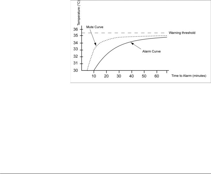
If the humidification chamber temperature is below 35.5 °C for 25 seconds, the lung symbol will light. If the temperature remains below this level for too long, then a low humidity alarm is activated.
The time taken for the humidifier to alarm is dependent on how far below the 35.5 °C threshold the temperature is.
The following Figure shows the relationship between temperature and the time before a warning or alarm is generated:
Figure 2 Temperature vs time to alarm
Pressing the mute button silences the audible low humidity alarm for 1 minute if the same temperature of the humidification chamber temperature probe is maintained.
The low humidity warning and alarm can occur under the following conditions:
–Cold
–Drafts
–Gas flow rates outside specification of breathing circuit
–Gas flow rates outside specification of humidification chamber
–Gas flow rates outside specification of humidifier.
12 |
5697.500 |
For internal use only. Copyright reserved. |
Version 1.2 Released Printed on 10.05.06 F5697500T01.fm |

Annex
Parts catalog
Test List


Parts catalog
Fisher&Paykel MR 850
Revision: 2006-03-20 08:50:13
5697.500
Because you care
2
Temp.Sensoradapter |
Parts catalog |
|
|
Item |
Part No. |
Description |
Qty. |
Qty. |
Remark |
No. |
unit |
||||
|
8411044 |
PROBE-THERMOMETER HOUSING DRAE |
1.000 |
St |
|
|
Items that are shown in the illustration but are not listed below the illustration are not available as spare parts |
|
|
|
|
5697.500 |
Revision: 2006-03-20 08:50:13 |
|
|
3 |
|
 Loading...