


Fiat Uno
Service and Repair Manual
Peter G Strasman
(923-320-3Y7)
Models covered
Fiat Uno 45, 55, 60, 70, 1.1 and 1.4, including Turbo ie and special/limited editions
903 cc, 999 cc, 1108 cc, 1116 cc, 1299 cc, 1301 cc and 1372 cc petrol engines with manual transmissions
Does not Selecta, Fiorino type vans or Diesel engine
© Haynes Publishing 1996 |
ABCDE |
FGHIJ |
|
|
KLMNO |
A book in the Haynes Service and Repair Manual Series |
PQRST |
1 2 3 |
All rights reserved. No part of this book may be reproduced or transmitted in any form or by any means, electronic or mechanical, including photocopying, recording or by any information storage or retrieval system, without permission in writing from the copyright holder.
ISBN 1 85960 089 1
British Library Cataloguing in Publication Data
A catalogue record for this book is available from the British Library.
Printed by J H Haynes & Co. Ltd, Sparkford, Nr Yeovil,
Somerset BA22 7JJ
Haynes Publishing
Sparkford, Nr Yeovil, Somerset BA22 7JJ, England
Haynes North America, Inc
861 Lawrence Drive, Newbury Park, California 91320, USA
Editions Haynes S.A.
147/149, rue Saint Honoré, 75001 Paris, France
Haynes Publishing Nordiska AB
Fyrisborgsgatan 5, 754 50 Uppsala, Sverige

Contents
LIVING WITH YOUR FIAT UNO
Introduction |
Page |
0•4 |
Safety First! |
Page |
0•5 |
|
|
|
General dimensions, weights and capacities |
Page |
0•6 |
|
|
|
Roadside Repairs
Jump starting |
Page |
0•7 |
Jacking, towing and wheel changing |
Page |
0•8 |
|
|
|
Identifying leaks |
Page |
0•9 |
|
|
|
Routine Maintenance and Servicing
Maintenance schedule (also see Chapter 13) |
Page |
0•10 |
Recommended Lubricants and Fluids |
Page |
0•13 |
|
|
|
Conversion factors |
Page |
0•14 |
|
|
|

Contents
REPAIRS & OVERHAUL
Engine and Associated Systems
Engine (also see Chapter 13) |
Page |
1•1 |
Cooling and heating systems (also see Chapter 13) |
Page |
2•1 |
|
|
|
Fuel system (also see Chapter 13) |
Page |
3•1 |
|
|
|
Ignition system (also see Chapter 13) |
Page |
4•1 |
|
|
|
Transmission
Clutch (also see Chapter 13) |
Page |
5•1 |
Transmission (also see Chapter 13) |
Page |
6•1 |
|
|
|
Driveshafts, hubs, roadwheels and tyres (also see Chapter 13) |
Page |
7•1 |
|
|
|
Brakes
Braking system (also see Chapter 13) Page 8•1
Electrical
Electrical system (also see Chapter 13) Page 9•1
Steering and suspension
Steering |
Page |
10•1 |
Suspension (also see Chapter 13) |
Page |
11•1 |
|
|
|
Bodywork
Bodywork (also see Chapter 13) Page 12•1
Additional information
Supplement: Revisions and information on later models Page 13•1
Wiring Diagrams
Page 14•1
REFERENCE
MOT Test Checks |
Page |
REF•1 |
Tools and Working Facilities |
Page |
REF•5 |
|
|
|
General Repair Procedures |
Page |
REF•8 |
|
|
|
Fault Finding |
Page |
REF•9 |
|
|
|
Buying Spare Parts & Vehicle Identification Numbers |
Page |
REF•12 |
|
|
|
Glossary of Technical Terms |
Page |
REF•13 |
|
|
|
Index |
Page |
REF•17 |
|
|
|
0•4 Introduction
Introduction to the Fiat Uno
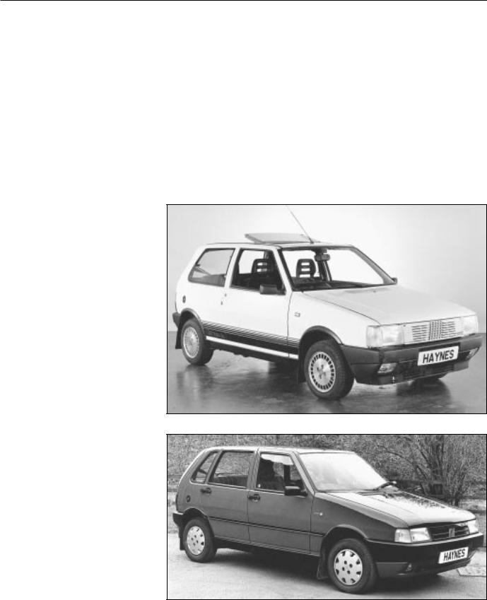
The Fiat Uno is a well designed and constructed car having an excellent power-to-weight ratio.
The car is very economical, but still offers good performance with excellent body interior space.
Attractive features include the options available for fouror five-speeds or threeor five-door bodywork.
All essential accessories, except a radio, are fitted as standard and a sunroof is optionally available.
From the home mechanic’s point of view all repair and servicing operations are straightforward without the need for special tools. Spare parts are immediately available at moderate cost.
Acknowledgements
Thanks are due to Champion Spark Plug who supplied the illustrations showing spark plug conditions. Certain other illustrations are the copyright of the Fiat Motor Company (UK) Limited and are used with their permission. Thanks are also due to Sykes-Pickavant Limited, who provided some of the workshop tools, and to all those people at Sparkford who helped in the production of this manual.
We take great pride in the accuracy of information given in this manual, but vehicle manufacturers make alterations and design changes during the production run of a particular vehicle of which they do not inform us, No liability can be accepted by the authors or publishers for loss, damage or injury caused by any errors in, or omissions from, the information given.
Fiat Uno 1301 cc Turbo ie
Fiat Uno 1372 cc 70 SX ie

Working on your car can be dangerous. This page shows just some of the potential risks and hazards, with the aim of creating a safety-conscious attitude.
General hazards
Scalding
•Don’t remove the radiator or expansion tank cap while the engine is hot.
•Engine oil, automatic transmission fluid or power steering fluid may also be dangerously hot if the engine has recently been running.
Burning
• Beware of burns from the exhaust system and from any part of the engine. Brake discs and drums can also be extremely hot immediately after use.
Crushing
•When working a raised vehicle, always supplement the jack with axle stands, or use drive-on ramps.
Never venture under a car
is only supported
•Take care if torque nuts Initial loosening be done with
Fire
•Fuel is highly explosive.
•Don’t let fuel
•Do not smoke (including pilot vehicle being creating sparks (electrically or by
•Fuel vapour is work on the fuel an inspection pit
•Another cause overload or short repairing or
•Keep a fire suitable for use
Electric shock
• Ignition HT voltage can be dangerous, especially to people with heart problems or a pacemaker. Don’t work on or near ignition system the engine running
the ignition switched on.
• Mains voltage is also dangerous. Make sure that any mains-operated equipment is correctly earthed. Mains power points should be protected by a residual current device (RCD) circuit breaker.
Fume or gas intoxication
•Exhaust fumes are poisonous; they contain carbon monoxide, which is rapidly fatal if inhaled Never run the engine in a
confined space such as a garage with the doors shut
•Fuel vapour is also poisonous, as are cleaning solvents
your pocket.
• Air conditioning poisonous gas if (including a cigarette) burns on contact.
Safety First! 0•5
Special hazards
Hydrofluoric acid
• This extremely corrosive acid is formed when certain types of synthetic rubber, found in some O-rings, oil seals, fuel hoses etc, are exposed to temperatures above 4000C. The
changes into a charred or sticky containing the acid. Once formed,
remains dangerous for years. If it the skin, it may be necessary to the limb concerned.
dealing with a vehicle which has
a fire, or with components salvaged a vehicle, wear protective gloves
them after use.
battery
• Batteries contain sulphuric acid, which attacks clothing, eyes and skin. Take care
topping-up or carrying the battery. hydrogen gas given off by the battery
explosive. Never cause a spark or naked light nearby. Be careful when and disconnecting battery
or jump leads.
can cause injury if they go off
. Take care when removing the wheel and/or facia. Special storage
instructions may apply.
Diesel injection equipment
• Diesel injection pumps supply fuel at very high pressure. Take care when working on the fuel injectors and fuel pipes.
Asbestos
• Asbestos dust can |
Warning: Never expose the hands, |
or swallowed. |
face or any other part of the body |
gaskets and in brake |
to injector spray; the fuel can |
When dealing with |
penetrate the skin with potentially fatal |
safest to assume |
results. |
Remember... |
A few tips |
|
DO |
DON’T |
|
• Do use eye protection when using power |
• Don’t attempt to lift a heavy component |
|
tools, and when working under the vehicle. |
which may be beyond your capability – get |
|
• Do wear gloves or use barrier cream to |
assistance. |
|
• Don’t rush to finish a job, or take |
||
protect your hands when necessary. |
||
• Do get someone to check periodically |
unverified short cuts. |
|
• Don’t use ill-fitting tools which may slip |
||
that all is well when working alone on the |
||
vehicle. |
and cause injury. |
|
• Do keep loose clothing and long hair well |
• Don’t leave tools or parts lying around |
|
out of the way of moving mechanical parts. |
where someone can trip over them. Mop |
|
• Do remove rings, wristwatch etc, before |
up oil and fuel spills at once. |
|
• Don’t allow children or pets to play in or |
||
working on the vehicle – especially the |
||
electrical system. |
near a vehicle being worked on. |
|
• Do ensure that any lifting or jacking |
|
|
equipment has a safe working load rating |
|
|
adequate for the job. |
|
|
|
|

0•6 General dimensions, weights and capacities
Dimensions
Overall length . . . . . . . . . . . . . . . . . . . . . . . . . . . . . . . . . . . . . . . . . . . . . |
3644 mm (143.6 in) |
Overall width . . . . . . . . . . . . . . . . . . . . . . . . . . . . . . . . . . . . . . . . . . . . . . |
1555 mm (61.3 in) |
Height . . . . . . . . . . . . . . . . . . . . . . . . . . . . . . . . . . . . . . . . . . . . . . . . . . . |
1432 mm (56.4 in) |
Wheelbase . . . . . . . . . . . . . . . . . . . . . . . . . . . . . . . . . . . . . . . . . . . . . . . . |
2362 mm (93.1 in) |
Front track . . . . . . . . . . . . . . . . . . . . . . . . . . . . . . . . . . . . . . . . . . . . . . . . |
1340 mm (52.8 in) |
Rear track . . . . . . . . . . . . . . . . . . . . . . . . . . . . . . . . . . . . . . . . . . . . . . . . |
1300 mm (51.2 in) |
Weights (kerb)
Uno 45: |
|
Three-door . . . . . . . . . . . . . . . . . . . . . . . . . . . . . . . . . . . . . . . . . . . . . . |
700 kg (1543 lb) |
Five-door . . . . . . . . . . . . . . . . . . . . . . . . . . . . . . . . . . . . . . . . . . . . . . . |
710 kg (1566 lb) |
Uno 55: |
|
Three-door . . . . . . . . . . . . . . . . . . . . . . . . . . . . . . . . . . . . . . . . . . . . . . |
730 kg (1610 lb) |
Five-door . . . . . . . . . . . . . . . . . . . . . . . . . . . . . . . . . . . . . . . . . . . . . . . |
740 kg (1632 lb) |
Uno 70: |
|
Three-door . . . . . . . . . . . . . . . . . . . . . . . . . . . . . . . . . . . . . . . . . . . . . . |
740 kg (1632 lb) |
Five-door . . . . . . . . . . . . . . . . . . . . . . . . . . . . . . . . . . . . . . . . . . . . . . . |
750 kg (1654 lb) |
Uno SX: |
|
Three-door . . . . . . . . . . . . . . . . . . . . . . . . . . . . . . . . . . . . . . . . . . . . . . |
770 kg (1698 lb) |
Five-door . . . . . . . . . . . . . . . . . . . . . . . . . . . . . . . . . . . . . . . . . . . . . . . |
780 kg (1720 lb) |
Capacities
Fuel tank . . . . . . . . . . . . . . . . . . . . . . . . . . . . . . . . . . . . . . . . . . . . . . . . . |
42.0 litre (9.25 gal) |
Engine oil (with filter change): |
|
903 cc engine . . . . . . . . . . . . . . . . . . . . . . . . . . . . . . . . . . . . . . . . . . . |
3.42 litre (6.0 pint) |
1116 and 1301 cc engines . . . . . . . . . . . . . . . . . . . . . . . . . . . . . . . . . |
4.10 Iitre (7.2 pint) |
Transmission . . . . . . . . . . . . . . . . . . . . . . . . . . . . . . . . . . . . . . . . . . . . . . |
2.40 litre (4.2 pint) |
Steering box . . . . . . . . . . . . . . . . . . . . . . . . . . . . . . . . . . . . . . . . . . . . . . |
140.0 cc |
Driveshaft CV joints . . . . . . . . . . . . . . . . . . . . . . . . . . . . . . . . . . . . . . . . . |
125.0 cc |
Cooling system: |
|
903 cc engine . . . . . . . . . . . . . . . . . . . . . . . . . . . . . . . . . . . . . . . . . . . |
4.6 litre (8.1 pint) |
1116 cc engine . . . . . . . . . . . . . . . . . . . . . . . . . . . . . . . . . . . . . . . . . . |
6.0 litre (10.6 pint) |
1301 cc engine . . . . . . . . . . . . . . . . . . . . . . . . . . . . . . . . . . . . . . . . . . |
6.2 litre (10.9 pint) |
For information applicable to later models, see Supplement at end of manual

Roadside Repairs 0•7
Jump starting will get you out of trouble, but you must correct
 whatever made the battery go flat in the first place. There are three possibilities:
1The battery has been drained by repeated attempts to start, or by
leaving the lights on.
2The charging system is not working properly (alternator drivebelt slack
or broken, alternator wiring fault or alternator itself faulty).
3The battery itself is at fault (electrolyte low, or battery worn out).
Booster battery (jump) startingJump starting
When jump-starting a car using a booster battery, observe the following precautions:
Before connecting the booster battery, make sure that the ignition is switched off.
Ensure that all electrical equipment (lights, heater, wipers, etc) is switched off.
Make sure that the booster battery is the same voltage as the discharged one in the vehicle.
If the battery is being jump-started from the battery in another vehicle, the two vehcles MUST NOT TOUCH each other.
Make sure that the transmission is in neutral (or PARK, in the case of automatic transmission).
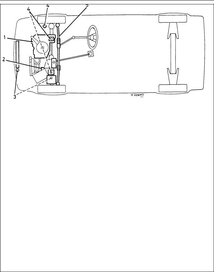
1
the positive (+) terminal of the flat battery
 +
+
 –
–
|
|
|
|
|
|
|
|
3 |
|
2 |
Connect the other end of the red lead to |
Connect one end of the black jump lead |
||
|
the positive (+) terminal of the booster |
|
to the negative (-) terminal of the |
|
|
battery. |
|
booster battery |
|
|
|
|
|
|
|
|
|
|
|
 +
+
 –
–
4 |
jump lead to a bolt or bracket on the |
|
|
engine block, well away from the |
|
|
battery, on the vehicle to be started. |
|
|
Make sure that the jump leads will not |
|
|
||
5 |
||
come into contact with the fan, drive- |
||
|
belts or other moving parts of the |
|
|
engine. |
|
|
Start the engine using the booster |
|
6 |
||
battery, then with the engine running at |
idle speed, disconnect the jump leads in the reverse order of connection.
0•8 Roadside Repairs
Jacking, towing and wheel changing
To avoid repetition, the procedure for raising the vehicle, in order to carry out work under it, is not included before each relevant operation described in this Manual.
It is to be preferred, and it is certainly recommended, that the vehicle is positioned over an inspection pit or raised on a lift. Where these facilities are not available, use ramps or jack up the vehicle strictly in accordance with the following guide. Once the vehicle is raised, supplement the jack with axle stands.
To raise the front end with a garage jack, locate the jack under the transmission lower mounting, just below and slightly to the rear of the transmission oil drain plug. Protect the mounting by placing a block of wood between the jack head and the mounting.
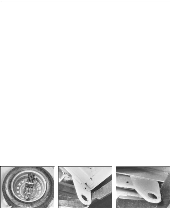
To raise the rear of the car, the jack should be placed under the spare wheel housing as far to the rear as possible. Place a wooden bearer between the jack head and the housing.
Jacking
The jack supplied with the car should only be used to change a wheel. Do not use this jack when overhaul or repair work is being carried out; employ a hydraulic or screw jack and supplement it with axle stands.
Jacking points are located under the sills for use with the jack supplied.
Towing
When being towed, use the left-hand front towing eye.
When towing another vehicle, use the rear towing eye adjacent to the exhaust tailpipe.
When being towed, remember that the brake pedal will require heavier pressure due to lack of servo assistance. Always turn the
ignition key to MAR to retain the steering in the unlocked position.
Wheel changing
With the car on firm level ground, apply the handbrake fully. Remove the hub cap or wheel trim, if fitted.
Release, but do not remove, the bolts. Chock the front and rear of the opposite roadwheel and then raise the car using the sill jack supplied with the car if it is being done at the roadside. Alternatively use a workshop jack supplemented with axle stands.
Remove the wheel bolts, change the wheel and screw in the bolts finger tight. It is recommended that the bolt threads are smeared with multi-purpose grease. Lower the car, remove the jack and tighten the wheel bolts to the specified torque. Refit any wheel trim that was removed.
Spare wheel and jack stowage |
Front tow hook |
Rear tow hook |

Roadside Repairs 0•9
Puddles on the garage floor or drive, or obvious wetness under the bonnet or underneath the car, suggest a leak that needs investigating. It can sometimes be difficult to decide where the leak is coming from, especially if the engine bay is very dirty already. Leaking oil or fluid can also be blown rearwards by the passage of air under the car, giving a false impression of where the problem lies.
Warning: Most automotive oils and fluids are poisonous. Wash them off skin, and change out of contaminated clothing, without delay.
Identifying leaks
The smell of a fluid leaking from the car may provide a


 clue to what’s leaking. Some fluids are distinctively
coloured. It may help to clean the car and to park it over some clean paper as an aid to locating the source of the leak. Remember that some leaks may only occur while the engine is running.
Sump oil |
|
Oil from filter |
|
Gearbox oil |
|
|
|
|
|
...or from the base of the oil filter.
Gearbox oil can leak from the seals at the inboard ends of the driveshafts.
Antifreeze |
|
Brake fluid |
|
Power steering fluid |
|
|
|
|
|
Leaking antifreeze often leaves a crystalline deposit like this.
A leak occurring at a wheel is almost certainly brake fluid.
Power steering fluid may leak from the pipe connectors on the steering rack.

0•10 Routine maintenance
Maintenance is essential for ensuring safety and desirable for the purpose of getting the best in terms of performance and economy from the car. Over the years the need for periodic lubrication has been greatly reduced if not totally eliminated. This has unfortunately tended to lead some owners to think that because no such action is required the items either no longer exist or will last forever. This is certainly not the case; it is essential to carry out regular visual examinations as comprehensively as possible in order to spot any possible defects at an early stage before they develop into major and expensive repairs.
For information applicable to later models, see Supplement.
Every 250 miles (400 km), weekly, or before a long journey
mCheck engine oil level
mCheck brake reservoir fluid level
mCheck tyre pressures
mCheck operation of all lights and horn
mTop up washer fluid reservoirs, adding a screen wash, and check operation of washers and wipers
mCheck coolant level
mCheck battery electrolyte level
Every 6000 miles (10 000 km)
or six months, whichever comes first
mRenew engine oil and filter (Chapter 1, Section 2)
mCheck drivebelt tension (Chapter 2, Section 8)
mCheck carburettor idle speed and mixture adjustments (Chapter 3)
mCheck contact points and dwell angle (mechanical breaker distributors) (Chapter 4, Section 3)
mCheck tyre tread wear (Chapter 7, Section 7)
mCheck disc pads for wear (Chapter 8, Section 3)
mCheck exhaust system for corrosion (Chapter 3, Section 19)
mRenew contact breaker points and adjust dwell angle (mechanical breaker distributors) (Chapter 4, Section 3)
mCheck and adjust ignition timing (Chapter 4, Section 4)
mRenew spark plugs (Chapter 4, Section 11)
mCheck clutch adjustment (Chapter 5, Section 2)
mCheck transmission oil level (Chapter 6, Section 2)
mCheck driveshaft and steering rack gaiters for splits (Chapters 7 and 10)
mCheck rear brake shoe linings for wear (Chapter 8, Section 4)
mCheck handbrake travel (Chapter 8, Section 16)
mCheck headlamp beam alignment (Chapter 9, Section 17)
mCheck balljoints for wear (Chapter 10, Section 2)
mCheck front wheel alignment (Chapter 10, Section 8)
mCheck suspension bushes for wear (Chapter 11, Section 2)
mCheck seat belts for fraying (Chapter 12, Section 23)
mLubricate controls, hinges and locks
Every 24 000 miles (40 000 km)
or two years, whichever comes first
mRenew coolant anti-freeze mixture (Chapter 2, Section 3)
mRenew transmission oil (Chapter 6, Section 2)
mRenew brake hydraulic fluid (Chapter 8, Section 12)
mCheck for underbody corrosion and clean out door and sill drain holes (Chapter 12, Section 2)
Every 12 000 miles (20 000 km) or 12 months, whichever comes first
mCheck and adjust valve clearances (Chapter 1, Sections 5 and 26)
mRenew air cleaner element (Chapter 3, Section 2)
Every 36 000 miles (60 000 km)
or three years, whichever comes first
mRenew the timing belt - 1116 and 1299/1301 cc (Chapter 1, Section 28)

Routine maintenance 0•11
|
|
Engine compartment (air cleaner removed for clarity) on 55S model |
|
|
|||
1 |
Strut upper mounting |
5 |
Throttle cable |
9 |
Distributor |
12 |
Radiator |
2 |
Washer fluid reservoir |
6 |
Carburettor |
10 |
Oil filler cap |
13 |
Coolant expansion tank |
3 |
Brake fluid reservoir |
7 |
Battery |
11 |
Radiator electric cooling |
14 |
Front mounting |
4 |
Ignition coil |
8 |
Timing belt cover |
|
fan |
15 |
Clutch operating cable |

0•12 Routine maintenance
|
View of front end from below on |
|
55S model |
1 |
Tie-rod end |
2 |
Track control arm |
3 |
Lower mounting |
4 |
Gearchange control rods |
5 |
Exhaust pipe |
6 |
Driveshafts |
7 |
Transmission |
8 |
Sump drain plug |
9 |
Disc caliper |
10 |
Front mounting |
11 |
Horns |
12 |
Radiator |
13 |
Oil filter |
View of rear end from below
1Suspension trailing arm
2Fuel tank filler hose
3Rear axle beam
4Rear silencer
5Spring seat
6Expansion box
7Handbrake cable
8Fuel tank support strap
9Fuel tank
10Handbrake cable adjuster
Lubricants and Fluids 0•13
Component or system
1Engine
2Transmission:
1372 cc Turbo ie model All other models
3Cooling system
4Brake and clutch hydraulic system(s)
5Driveshaft CV joints and steering rack General greasing
Lubricant type/specification
Multigrade engine oil, viscosity SAE 15W/40, meeting API-SG or CCMC G2/G3 specification (or equivalent multigrade engine oil with viscosity rating suitable for ambient temperature in which vehicle is operated - see owner’s handbook)
FIAT ZC 80/S gear oil
FIAT ZC 90 gear oil
Ethylene glycol based antifreeze
Hydraulic fluid to DOT 3 or 4, or SAE J1703C
Lithium based molybdenum disulphide
Multi-purpose lithium based grease

0•14 Conversion Factors
Length (distance)
Inches (in) |
x 25.4 |
= |
Millimetres (mm) |
x |
0.0394 = |
Inches (in) |
|
Feet (ft) |
x 0.305 |
= |
Metres (m) |
x |
3.281 |
= |
Feet (ft) |
Miles |
x 1.609 |
= |
Kilometres (km) |
x |
0.621 |
= |
Miles |
Volume (capacity)
Cubic inches (cu in; in3) Imperial pints (Imp pt) Imperial quarts (Imp qt) Imperial quarts (Imp qt) US quarts (US qt) Imperial gallons (Imp gal) Imperial gallons (Imp gal) US gallons (US gal)
x |
16.387 = |
Cubic centimetres (cc; cm3) |
|
x |
0.568 |
= |
Litres (l) |
x |
1.137 |
= |
Litres (l) |
x 1.201 |
= |
US quarts (US qt) |
|
x |
0.946 |
= |
Litres (l) |
x |
4.546 |
= |
Litres (l) |
x |
1.201 |
= |
US gallons (US gal) |
x |
3.785 |
= |
Litres (l) |
x |
0.061 |
= Cubic inches (cu in; in3) |
x |
1.76 |
= Imperial pints (Imp pt) |
x |
0.88 |
= Imperial quarts (Imp qt) |
x |
0.833 |
= Imperial quarts (Imp qt) |
x 1.057 |
= US quarts (US qt) |
|
x |
0.22 |
= Imperial gallons (Imp gal) |
x |
0.833 |
= Imperial gallons (Imp gal) |
x |
0.264 |
= US gallons (US gal) |
Mass (weight)
Ounces (oz) |
x |
28.35 |
= |
Grams (g) |
x |
0.035 |
= |
Ounces (oz) |
Pounds (lb) |
x |
0.454 |
= |
Kilograms (kg) |
x |
2.205 |
= |
Pounds (lb) |
Force
Ounces-force (ozf; oz) |
x |
0.278 |
= |
Newtons (N) |
x |
3.6 |
= |
Ounces-force (ozf; oz) |
Pounds-force (lbf; lb) |
x |
4.448 |
= |
Newtons (N) |
x |
0.225 |
= |
Pounds-force (lbf; lb) |
Newtons (N) |
x |
0.1 |
= |
Kilograms-force (kgf; kg) |
x |
9.81 |
= |
Newtons (N) |
Pressure
Pounds-force per square inch |
x |
0.070 |
= |
Kilograms-force per square |
(psi; lbf/in2; lb/in2) |
|
|
|
centimetre (kgf/cm2; kg/cm2) |
Pounds-force per square inch |
x 0.068 |
= |
Atmospheres (atm) |
|
(psi; lbf/in2; lb/in2) |
|
|
|
|
Pounds-force per square inch |
x |
0.069 |
= |
Bars |
(psi; lbf/in2; lb/in2) |
|
|
|
|
Pounds-force per square inch |
x |
6.895 |
= |
Kilopascals (kPa) |
(psi; lbf/in2; lb/in2) |
|
|
|
|
Kilopascals (kPa) |
x |
0.01 |
= |
Kilograms-force per square |
|
|
|
|
centimetre (kgf/cm2; kg/cm2) |
Millibar (mbar) |
x |
100 |
= |
Pascals (Pa) |
Millibar (mbar) |
x |
0.0145 = |
Pounds-force per square inch |
|
|
|
|
|
(psi; lbf/in2; lb/in2) |
Millibar (mbar) |
x |
0.75 |
= |
Millimetres of mercury (mmHg) |
Millibar (mbar) |
x |
0.401 |
= |
Inches of water (inH2O) |
Millimetres of mercury (mmHg) |
x |
0.535 |
= |
Inches of water (inH2O) |
Inches of water (inH2O) |
x |
0.036 |
= |
Pounds-force per square inch |
Torque (moment of force) |
|
(psi; lbf/in2; lb/in2) |
||
|
|
|||
Pounds-force inches |
x |
1.152 |
= |
Kilograms-force centimetre |
(lbf in; lb in) |
|
|
|
(kgf cm; kg cm) |
Pounds-force inches |
x 0.113 |
= |
Newton metres (Nm) |
|
(lbf in; lb in) |
|
|
|
|
Pounds-force inches |
x |
0.083 |
= |
Pounds-force feet (lbf ft; lb ft) |
(lbf in; lb in) |
|
|
|
|
Pounds-force feet (lbf ft; lb ft) |
x |
0.138 |
= |
Kilograms-force metres |
|
|
|
|
(kgf m; kg m) |
Pounds-force feet (lbf ft; lb ft) |
x |
1.356 |
= |
Newton metres (Nm) |
Newton metres (Nm) |
x 0.102 |
= |
Kilograms-force metres |
|
|
|
|
|
(kgf m; kg m) |
x |
14.223 = |
Pounds-force per square inch |
|
|
|
|
(psi; lbf/in2; lb/in2) |
x |
14.696 = |
Pounds-force per square inch |
|
|
|
|
(psi; lbf/in2; lb/in2) |
x |
14.5 |
= |
Pounds-force per square inch |
|
|
|
(psi; lbf/in2; lb/in2) |
x |
0.145 |
= |
Pounds-force per square inch |
|
|
|
(psi; lbf/in2; lb/in2) |
x |
98.1 |
= |
Kilopascals (kPa) |
x |
0.01 |
= |
Millibar (mbar) |
x |
68.947 = |
Millibar (mbar) |
|
x |
1.333 |
= |
Millibar (mbar) |
x |
2.491 |
= |
Millibar (mbar) |
x |
1.868 |
= |
Millimetres of mercury (mmHg) |
x |
27.68 |
= |
Inches of water (inH2O) |
x |
0.868 |
= |
Pounds-force inches |
|
|
|
(lbf in; lb in) |
x |
8.85 |
= |
Pounds-force inches |
|
|
|
(lbf in; lb in) |
x 12 |
= |
Pounds-force inches |
|
|
|
|
(lbf in; lb in) |
x |
7.233 |
= |
Pounds-force feet (lbf ft; lb ft) |
x |
0.738 |
= |
Pounds-force feet (lbf ft; lb ft) |
x 9.804 |
= |
Newton metres (Nm) |
|
Power
Horsepower (hp) x 745.7 = Watts (W) x 0.0013 = Horsepower (hp)
Velocity (speed)
Miles per hour (miles/hr; mph) x 1.609 = Kilometres per hour (km/hr; kph) x 0.621 = Miles per hour (miles/hr; mph)
Fuel consumption*
Miles per gallon (mpg) x 0.354 = Kilometres per litre (km/l) x 2.825 = Miles per gallon (mpg)
Temperature
Degrees Fahrenheit = (°C x 1.8) + 32 Degrees Celsius (Degrees Centigrade; °C) = (°F - 32) x 0.56
* It is common practice to convert from miles per gallon (mpg) to litres/100 kilometres (l/100km), where mpg x l/100 km = 282

1•1
Chapter 1 Engine
For modifications, and information applicable to later models, see Supplement at end of manual
Contents
Part 1: General
Crankcase ventilation system . . . . . . . . . . . . . . . . . . . . . . . . . . . . . . 3 Description . . . . . . . . . . . . . . . . . . . . . . . . . . . . . . . . . . . . . . . . . . . . 1 Engine oil and filter . . . . . . . . . . . . . . . . . . . . . . . . . . . . . . . . . . . . . . 2 Major operations possible without removing the engine
from the car . . . . . . . . . . . . . . . . . . . . . . . . . . . . . . . . . . . . . . . . . . 4
Part 2: 903 cc engine
Cylinder head - dismantling and decarbonising . . . . . . . . . . . . . . . . 17 Cylinder head - removal and refitting . . . . . . . . . . . . . . . . . . . . . . . . 7 Engine - complete dismantling . . . . . . . . . . . . . . . . . . . . . . . . . . . . . 16 Engine - complete reassembly . . . . . . . . . . . . . . . . . . . . . . . . . . . . . 20 Engine - dismantling (general) . . . . . . . . . . . . . . . . . . . . . . . . . . . . . . 14 Engine - initial start-up after overhaul or major repair . . . . . . . . . . . . 24 Engine - method of removal . . . . . . . . . . . . . . . . . . . . . . . . . . . . . . . 12 Engine - reassembly (general) . . . . . . . . . . . . . . . . . . . . . . . . . . . . . . 19 Engine - refitting ancillary components . . . . . . . . . . . . . . . . . . . . . . . 21 Engine - removing ancillary components . . . . . . . . . . . . . . . . . . . . . 15 Engine mountings - renewal . . . . . . . . . . . . . . . . . . . . . . . . . . . . . . . 11 Engine/transmission - reconnection . . . . . . . . . . . . . . . . . . . . . . . . . 22 Engine/transmission - refitting . . . . . . . . . . . . . . . . . . . . . . . . . . . . . 23 Engine/transmission - removal and separation . . . . . . . . . . . . . . . . . 13 Examination and renovation . . . . . . . . . . . . . . . . . . . . . . . . . . . . . . . 18 Fault finding - all engines . . . . . . . . . . . . . . . . . . . . See end of Chapter Oil pump - removal and refitting . . . . . . . . . . . . . . . . . . . . . . . . . . . . 10 Pistons/connecting rods - removal and refitting . . . . . . . . . . . . . . . . 9
Sump pan - removal and refitting . . . . . . . . . . . . . . . . . . . . . . . . . . . |
8 |
Timing chain and sprockets - removal and refitting . . . . . . . . . . . . . |
6 |
Valve clearances - adjustment . . . . . . . . . . . . . . . . . . . . . . . . . . . . . |
5 |
Part 3: 1116 cc and 1301 cc engines
Camshaft and camshaft carrier - removal and refitting . . . . . . . . . . |
27 |
|
|
Cylinder head - dismantling and decarbonising . . . |
. . . . . . . . . . . . . |
39 |
|
Cylinder head - removal and refitting . . . . . . . . . . . |
. . . . . . . . . . . . . |
29 |
|
Engine - complete dismantling . . . . . . . . . . . . . . . . |
. . . . . . . . . . . . . |
38 |
|
Engine - complete reassembly . . . . . . . . . . . . . . . . |
. . . . . . . . . . . . . |
42 |
|
Engine - dismantling (general) . . . . . . . . . . . . . . . . . |
. . . . . . . . . . . . . |
36 |
|
Engine - initial start-up after major overhaul . . . . . . |
. . . . . . . . . . . . . |
45 |
|
Engine - method of removal . . . . . . . . . . . . . . . . . . |
. . . . . . . . . . . . . |
34 |
|
Engine - reassembly (general) |
|
41 |
|
. . . . . . . . . . . . . |
1 |
||
Engine ancillary components - refitting . . . . . . . . . . |
. . . . . . . . . . . . . |
43 |
|
Engine ancillary components - removal . . . . . . . . . |
. . . . . . . . . . . . . |
37 |
|
. . . . . . . . . . . . . . . . . .Engine mountings - renewal |
. . . . . . . . . . . . . |
33 |
|
Engine/transmission - reconnection and refitting . . |
. . . . . . . . . . . . . |
44 |
|
Engine/transmission - removal and separation . . . . |
. . . . . . . . . . . . . |
35 |
|
Examination and renovation . . . . . . . . . . . . . . . . . . |
. . . . . . . . . . . . . |
40 |
|
Fault finding - all engines . . . . . . . . . . . . . . . . . . . . |
See end of Chapter |
|
|
Oil pump - removal and refitting . . . . . . . . . . . . . . . |
. . . . . . . . . . . . . |
31 |
|
Pistons/connecting rods - removal and refitting . . . |
. . . . . . . . . . . . . |
32 |
|
Sump pan - removal and refitting . . . . . . . . . . . . . . |
. . . . . . . . . . . . . |
30 |
|
Timing belt - renewal . . . . . . . . . . . . . . . . . . . . . . . . |
. . . . . . . . . . . . . |
28 |
|
Valve clearances - adjustment . . . . . . . . . . . . . . . . |
. . . . . . . . . . . . . |
26 |
|
Valve clearances - checking . . . . . . . . . . . . . . . . . |
. . . . . . . . . . . . . |
25 |
|
Degrees of difficulty
|
|
|
|
|
|
|
|
|
|
|
|
|
|
|
Easy, suitable for |
1 |
|
Fairly easy, suitable |
2 |
|
Fairly difficult, |
3 |
|
Difficult, suitable for |
4 |
|
Very difficult, |
5 |
|
|
|
|
|
|
||||||||||
novice with little |
|
for beginner with |
|
suitable for competent |
|
experienced DIY |
|
suitable for expert DIY |
|
|||||
experience |
|
some experience |
|
DIY mechanic |
|
mechanic |
|
or professional |
|
|||||
|
|
|
|
|
|
|
|
|
|
|
|
|
|
|
Specifications
903 cc engine
Type . . . . . . . . . . . . . . . . . . . . . . . . . . . . . . . . . . . . . . . . . . . . . . . . . . . |
Four cylinder in-line, liquid cooled, overhead valve. Transversely |
|
mounted with end-on transmission |
General |
|
Bore . . . . . . . . . . . . . . . . . . . . . . . . . . . . . . . . . . . . . . . . . . . . . . . . . . . . |
65.0 mm (2.56 in) |
Stroke . . . . . . . . . . . . . . . . . . . . . . . . . . . . . . . . . . . . . . . . . . . . . . . . . . . |
68.0 mm (2.68 in) |
Displacement . . . . . . . . . . . . . . . . . . . . . . . . . . . . . . . . . . . . . . . . . . . . . |
903 cc (55 cu in) |
Compression ratio: |
|
900 models . . . . . . . . . . . . . . . . . . . . . . . . . . . . . . . . . . . . . . . . . . . . . |
9.0 : 1 |
900 ES models . . . . . . . . . . . . . . . . . . . . . . . . . . . . . . . . . . . . . . . . . . |
9.7 : 1 |
Maximum power (DIN) . . . . . . . . . . . . . . . . . . . . . . . . . . . . . . . . . . . . . . |
33.1 kW at 5600 rev/min (45 bhp) |
Maximum torque (DIN): |
|
900 models . . . . . . . . . . . . . . . . . . . . . . . . . . . . . . . . . . . . . . . . . . . . . |
68 Nm at 3000 rev/min (49 lbf ft) |
900 ES models . . . . . . . . . . . . . . . . . . . . . . . . . . . . . . . . . . . . . . . . . . |
69 Nm at 3000 rev/min (51 lbf ft) |
Compression pressure . . . . . . . . . . . . . . . . . . . . . . . . . . . . . . . . . . . . . . |
9.3 to 10.35 bar (135 to 150 lbf/in2) |
Maximum pressure difference between cylinders . . . . . . . . . . . . . . . . . |
0.69 bar (10 lbf/in2) |
Firing order . . . . . . . . . . . . . . . . . . . . . . . . . . . . . . . . . . . . . . . . . . . . . . . |
1 - 3 - 4 - 2 (No. 1 at crankshaft pulley end) |

1•2 Engine – general
Cylinder block and crankcase
Material . . . . . . . . . . . . . . . . . . . . . . . . . . . . . . . . . . . . . . . . . . . . . . . . . . |
Cast-iron |
Bore diameter . . . . . . . . . . . . . . . . . . . . . . . . . . . . . . . . . . . . . . . . . . . . . |
65.000 to 65.050 mm (2.5591 to 2.5610 in) |
Diameter of camshaft bearing bores in crankcase timing gear end: |
|
Grade B . . . . . . . . . . . . . . . . . . . . . . . . . . . . . . . . . . . . . . . . . . . . . . . . |
50.505 to 50.515 mm (1.9882 to 1.9886 in) |
Grade C . . . . . . . . . . . . . . . . . . . . . . . . . . . . . . . . . . . . . . . . . . . . . . . . |
50.515 to 50.525 mm (1.9886 to 1.9890 in) |
Grade D . . . . . . . . . . . . . . . . . . . . . . . . . . . . . . . . . . . . . . . . . . . . . . . . |
50.705 to 50.715 mm (1.9960 to 1.9964 in) |
Grade E . . . . . . . . . . . . . . . . . . . . . . . . . . . . . . . . . . . . . . . . . . . . . . . . |
50.715 to 50.725 mm (1.9964 to 1.9968 in) |
Centre . . . . . . . . . . . . . . . . . . . . . . . . . . . . . . . . . . . . . . . . . . . . . . . . . . . |
46.420 to 46.450 mm (1.8275 to 1.8287 in) |
Flywheel end . . . . . . . . . . . . . . . . . . . . . . . . . . . . . . . . . . . . . . . . . . . . . . |
35.921 to 35.951 mm (1.4142 to 1.4154 in) |
Maximum cylinder bore taper . . . . . . . . . . . . . . . . . . . . . . . . . . . . . . . . . |
0.015 mm (0.0006 in) |
Maximum cylinder bore ovality . . . . . . . . . . . . . . . . . . . . . . . . . . . . . . . . |
0.015 mm (0.0006 in) |
Pistons and piston rings
Piston diameter: |
|
Grade A . . . . . . . . . . . . . . . . . . . . . . . . . . . . . . . . . . . . . . . . . . . . . . . . |
64.940 to 64.950 mm (2.5566 to 2.5570 in) |
Grade C . . . . . . . . . . . . . . . . . . . . . . . . . . . . . . . . . . . . . . . . . . . . . . . . |
64.960 to 64.970 mm (2.5574 to 2.5578 in) |
Grade E . . . . . . . . . . . . . . . . . . . . . . . . . . . . . . . . . . . . . . . . . . . . . . . . |
64.980 to 64.990 mm (2.5582 to 2.5586 in) |
Oversizes . . . . . . . . . . . . . . . . . . . . . . . . . . . . . . . . . . . . . . . . . . . . . . . . |
0.2, 0.4, 0.6 mm (0.008, 0.016, 0.024 in) |
Piston clearance in cylinder bore . . . . . . . . . . . . . . . . . . . . . . . . . . . . . . |
0.050 to 0.070 mm (0.0020 to 0.0028 in) |
Piston ring groove width: |
|
Top . . . . . . . . . . . . . . . . . . . . . . . . . . . . . . . . . . . . . . . . . . . . . . . . . . . |
1.785 to 1.805 mm (0.0703 to 0.0711 in) |
Second . . . . . . . . . . . . . . . . . . . . . . . . . . . . . . . . . . . . . . . . . . . . . . . . |
2.015 to 2.035 mm (0.0793 to 0.0801 in) |
Bottom . . . . . . . . . . . . . . . . . . . . . . . . . . . . . . . . . . . . . . . . . . . . . . . . |
3.975 to 3.977 mm (0.1566 to 0.1567 in) |
Piston ring thickness: |
|
Top . . . . . . . . . . . . . . . . . . . . . . . . . . . . . . . . . . . . . . . . . . . . . . . . . . . |
1.728 to 1.740 mm (0.0680 to 0.0685 in) |
Second . . . . . . . . . . . . . . . . . . . . . . . . . . . . . . . . . . . . . . . . . . . . . . . . |
1.978 to 1.990 mm (0.0779 to 0.0784 in) |
Bottom . . . . . . . . . . . . . . . . . . . . . . . . . . . . . . . . . . . . . . . . . . . . . . . . |
3.925 to 3.937 mm (0.1545 to 0.1550 in) |
Piston ring groove clearance: |
|
Top . . . . . . . . . . . . . . . . . . . . . . . . . . . . . . . . . . . . . . . . . . . . . . . . . . . |
0.045 to 0.077 mm (0.0018 to 0.0030 in) |
Second . . . . . . . . . . . . . . . . . . . . . . . . . . . . . . . . . . . . . . . . . . . . . . . . |
0.025 to 0.057 mm (0.0010 to 0.0022 in) |
Bottom . . . . . . . . . . . . . . . . . . . . . . . . . . . . . . . . . . . . . . . . . . . . . . . . |
0.020 to 0.052 mm (0.0008 to 0.0020 in) |
Piston ring end gap: |
|
Top . . . . . . . . . . . . . . . . . . . . . . . . . . . . . . . . . . . . . . . . . . . . . . . . . . . |
0.25 to 0.45 mm (0.0098 to 0.0177 in) |
Second . . . . . . . . . . . . . . . . . . . . . . . . . . . . . . . . . . . . . . . . . . . . . . . . |
0.20 to 0.35 mm (0.0078 to 0.0137 in) |
Bottom . . . . . . . . . . . . . . . . . . . . . . . . . . . . . . . . . . . . . . . . . . . . . . . . |
0.20 to 0.45 mm (0.0078 to 0.0177 in) |
Oversize piston rings . . . . . . . . . . . . . . . . . . . . . . . . . . . . . . . . . . . . . . . |
0.2, 0.4, 0.6 mm (0.008, 0.016, 0.024 in) |
Gudgeon pin diameter: |
|
Grade 1 . . . . . . . . . . . . . . . . . . . . . . . . . . . . . . . . . . . . . . . . . . . . . . . . |
19.970 to 19.974 mm (0.7862 to 0.7863 in) |
Grade 2 . . . . . . . . . . . . . . . . . . . . . . . . . . . . . . . . . . . . . . . . . . . . . . . . |
19.974 to 19.978 mm (0.7863 to 0.7865 in) |
Grade 3 . . . . . . . . . . . . . . . . . . . . . . . . . . . . . . . . . . . . . . . . . . . . . . . . |
19.978 to 19.982 mm (0.7865 to 0.7866 in) |
Oversize . . . . . . . . . . . . . . . . . . . . . . . . . . . . . . . . . . . . . . . . . . . . . . . . . |
0.2 mm (0.008 in) |
Crankshaft
Journal diameter . . . . . . . . . . . . . . . . . . . . . . . . . . . . . . . . . . . . . . . . . . . |
50.785 to 50.805 mm (1.9994 to 2.0002 in) |
Standard main bearing shell thickness . . . . . . . . . . . . . . . . . . . . . . . . . . |
1.832 to 1.837 mm (0.0721 to 0.0723 in) |
Undersizes . . . . . . . . . . . . . . . . . . . . . . . . . . . . . . . . . . . . . . . . . . . . . . . |
0.254, 0.508, 0.762,1.016 mm (0.010, 0.020. 0.030, 0.040 in) |
Crankshaft endfloat . . . . . . . . . . . . . . . . . . . . . . . . . . . . . . . . . . . . . . . . |
0.06 to 0.26 mm (0.0024 to 0.0102 in) |
Crankpin diameter . . . . . . . . . . . . . . . . . . . . . . . . . . . . . . . . . . . . . . . . . |
39.985 to 40.005 mm (1.5741 to 1.5750 in) |
Standard big-end shell bearing thickness . . . . . . . . . . . . . . . . . . . . . . . |
1.807 to 1.813 mm (0.0712 to 0.0714 in) |
Undersizes . . . . . . . . . . . . . . . . . . . . . . . . . . . . . . . . . . . . . . . . . . . . . . . |
0.254, 0.508, 0.762, 1.016 mm (0.010, 0.020, 0.030, 0.040 in) |
Camshaft
Diameter of camshaft journals: |
|
Timing end . . . . . . . . . . . . . . . . . . . . . . . . . . . . . . . . . . . . . . . . . . . . . |
37.975 to 38.000 mm (1.4951 to 1.4961 in) |
Centre . . . . . . . . . . . . . . . . . . . . . . . . . . . . . . . . . . . . . . . . . . . . . . . . . |
43.348 to 43.373 mm (1.7079 to 1.7088 in) |
Flywheel end . . . . . . . . . . . . . . . . . . . . . . . . . . . . . . . . . . . . . . . . . . . . |
30.975 to 31.000 mm (1.2194 to 1.2205 in) |
Bush reamed diameters: |
|
Timing gear end* . . . . . . . . . . . . . . . . . . . . . . . . . . . . . . . . . . . . . . . . . |
38.025 to 38.050 mm (1.4971 to 1.4981 in) |
Centre . . . . . . . . . . . . . . . . . . . . . . . . . . . . . . . . . . . . . . . . . . . . . . . . . |
43.404 to 43.424 mm (1.7088 to 1.7096 in) |
Flywheel end . . . . . . . . . . . . . . . . . . . . . . . . . . . . . . . . . . . . . . . . . . . . |
31.026 to 31.046 mm (1.2215 to 1.2223 in) |
*Supplied reamed to size |
|
Cam lift . . . . . . . . . . . . . . . . . . . . . . . . . . . . . . . . . . . . . . . . . . . . . . . . . . |
5.1 mm (0.201 in) |
Outside diameter of cam follower . . . . . . . . . . . . . . . . . . . . . . . . . . . . . |
13.982 to 14.000 mm (0.5505 to 0.5512 in) |
Oversizes . . . . . . . . . . . . . . . . . . . . . . . . . . . . . . . . . . . . . . . . . . . . . . . . |
0.05 to 0.010 mm (0.002 to 0.004 in) |
Cam follower running clearance . . . . . . . . . . . . . . . . . . . . . . . . . . . . . . . |
0.010 to 0.046 mm (0.0004 to 0.0018 in) |
|
Engine – general 1•3 |
||
|
|
|
|
Cylinder head and valves |
|
|
|
Material (cylinder head) . . . . . . . . . . . . . . . . . . . . . . . . . . . . . . . . . . . . . . |
Light alloy |
||
Maximum distortion . . . . . . . . . . . . . . . . . . . . . . . . . . . . . . . . . . . . . . . . |
0.05 mm (0.002 in) |
||
Valve guide bore in head . . . . . . . . . . . . . . . . . . . . . . . . . . . . . . . . . . . . |
12.950 to 12.977 mm (0.5099 to 0.5109 in) |
||
Valve guide outside diameter . . . . . . . . . . . . . . . . . . . . . . . . . . . . . . . . . |
13.010 to 13.030 mm (0.5122 to 0.5130 in) |
||
Valve guide oversizes . . . . . . . . . . . . . . . . . . . . . . . . . . . . . . . . . . . . . . . |
0.5, 0.10, 0.25 mm (0.002, 0.004, 0.010 in) |
||
Inside diameter of valve guide (reamed) . . . . . . . . . . . . . . . . . . . . . . . . . |
7.022 to 7.040 mm (0.2765 to 0.2772 in) |
||
Guide fit in head (interference) . . . . . . . . . . . . . . . . . . . . . . . . . . . . . . . . |
0.033 to 0.080 mm (0.0013 to 0.0032 in) |
||
Valve stem diameter . . . . . . . . . . . . . . . . . . . . . . . . . . . . . . . . . . . . . . . . |
6.982 to 7.000 mm (0.2748 to 0.2756 in) |
||
Maximum clearance (valve stem to guide) . . . . . . . . . . . . . . . . . . . . . . . |
0.022 to 0.058 mm (0.0009 to 0.0023 in) |
||
Valve seat angle . . . . . . . . . . . . . . . . . . . . . . . . . . . . . . . . . . . . . . . . . . . |
44º 55’ to 45º 05’ |
||
Valve face angle . . . . . . . . . . . . . . . . . . . . . . . . . . . . . . . . . . . . . . . . . . . |
45º 25’ to 45º 35’ |
||
Valve head diameter: |
|
|
|
Inlet . . . . . . . . . . . . . . . . . . . . . . . . . . . . . . . . . . . . . . . . . . . . . . . . . . . |
29.0 mm (1.1417 in) |
||
Exhaust . . . . . . . . . . . . . . . . . . . . . . . . . . . . . . . . . . . . . . . . . . . . . . . . |
26.0 mm (1.0236 in) |
||
Contact band (valve to seat) . . . . . . . . . . . . . . . . . . . . . . . . . . . . . . . . . . |
1.3 to 1.5 mm (0.0512 to 0.0591 in) |
||
Valve clearance: |
|
|
|
Inlet . . . . . . . . . . . . . . . . . . . . . . . . . . . . . . . . . . . . . . . . . . . . . . . . . . . |
0.15 mm (0.006 in) |
||
Exhaust . . . . . . . . . . . . . . . . . . . . . . . . . . . . . . . . . . . . . . . . . . . . . . . . |
0.20 mm (0.008 in) |
||
For timing check . . . . . . . . . . . . . . . . . . . . . . . . . . . . . . . . . . . . . . . . . . . |
0.60 mm (0.024 in) |
||
Valve timing: |
|
|
|
Inlet valve: |
|
|
|
Opens . . . . . . . . . . . . . . . . . . . . . . . . . . . . . . . . . . . . . . . . . . . . . . . |
7º BTDC |
||
Closes . . . . . . . . . . . . . . . . . . . . . . . . . . . . . . . . . . . . . . . . . . . . . . . |
36º ABDC |
1 |
|
Exhaust valve: |
|
||
Opens . . . . . . . . . . . . . . . . . . . . . . . . . . . . . . . . . . . . . . . . . . . . . . . |
38º BBDC |
|
|
|
|||
Closes . . . . . . . . . . . . . . . . . . . . . . . . . . . . . . . . . . . . . . . . . . . . . . . |
5º ATDC |
||
Lubrication system
Oil pump type . . . . . . . . . . . . . . . . . . . . . . . . . . . . . . . . . . . . . . . . . . . . .
Tooth tip to body clearance . . . . . . . . . . . . . . . . . . . . . . . . . . . . . . . . . .
Gear endfloat . . . . . . . . . . . . . . . . . . . . . . . . . . . . . . . . . . . . . . . . . . . . .
Oil pressure at normal operating temperature and average road/ engine speed . . . . . . . . . . . . . . . . . . . . . . . . . . . . . . . . . . . . . . . . . . . . .
Oil capacity (with filter change) . . . . . . . . . . . . . . . . . . . . . . . . . . . . . . . .
Oil type/specification . . . . . . . . . . . . . . . . . . . . . . . . . . . . . . . . . . . . . . .
Oil filter . . . . . . . . . . . . . . . . . . . . . . . . . . . . . . . . . . . . . . . . . . . . . . . . . .
Gear, driven by shaft from camshaft 0.05 to 0.14 mm (0.0020 to 0.0055 in) 0.020 to 0.105 mm (0.0008 to 0.0041 in)
2.94to 3.92 bar (42 to 57 lbf/ in2)
3.42litre (6.0 pint)
Multigrade engine oil, viscosity SAE 15W/40 Champion C101
Torque wrench settings |
Nm |
lbf ft |
Cylinder head bolts: |
|
|
Stage 1 . . . . . . . . . . . . . . . . . . . . . . . . . . . . . . . . . . . . . . . . . . . . . . . . |
30 |
22 |
Stage 2 . . . . . . . . . . . . . . . . . . . . . . . . . . . . . . . . . . . . . . . . . . . . . . . . |
59 |
43.5 |
Camshaft sprocket bolt . . . . . . . . . . . . . . . . . . . . . . . . . . . . . . . . . . . . . |
49 |
36 |
Main bearing cap bolts . . . . . . . . . . . . . . . . . . . . . . . . . . . . . . . . . . . . . . |
69 |
51 |
Big-end bearing cap bolts . . . . . . . . . . . . . . . . . . . . . . . . . . . . . . . . . . . |
41 |
30 |
Crankshaft pulley nut . . . . . . . . . . . . . . . . . . . . . . . . . . . . . . . . . . . . . . . |
98 |
72 |
Flywheel bolts . . . . . . . . . . . . . . . . . . . . . . . . . . . . . . . . . . . . . . . . . . . . . |
44 |
32 |
Rocker pedestal nuts . . . . . . . . . . . . . . . . . . . . . . . . . . . . . . . . . . . . . . . |
39 |
29 |
Engine mounting bracket bolts . . . . . . . . . . . . . . . . . . . . . . . . . . . . . . . . |
25 |
18 |
Engine mounting centre nuts . . . . . . . . . . . . . . . . . . . . . . . . . . . . . . . . . |
49 |
36 |
Exhaust manifold nuts . . . . . . . . . . . . . . . . . . . . . . . . . . . . . . . . . . . . . . |
20 |
15 |
Spark plugs . . . . . . . . . . . . . . . . . . . . . . . . . . . . . . . . . . . . . . . . . . . . . . . |
25 |
18 |
Temperature sender switch . . . . . . . . . . . . . . . . . . . . . . . . . . . . . . . . . . |
49 |
36 |
Driveshaft to hub nuts . . . . . . . . . . . . . . . . . . . . . . . . . . . . . . . . . . . . . . |
272 |
200 |
Hub carrier to strut clamp bolts . . . . . . . . . . . . . . . . . . . . . . . . . . . . . . . |
49 |
36 |
Roadwheel bolts . . . . . . . . . . . . . . . . . . . . . . . . . . . . . . . . . . . . . . . . . . . |
86 |
63 |
Brake caliper mounting bolts . . . . . . . . . . . . . . . . . . . . . . . . . . . . . . . . . |
53 |
39 |
Tie-rod end balljoint nuts . . . . . . . . . . . . . . . . . . . . . . . . . . . . . . . . . . . . |
34 |
25 |
Driveshaft inboard boot retainer bolts . . . . . . . . . . . . . . . . . . . . . . . . . . |
9 |
7 |

1•4 Engine – general
1116 cc and 1301 cc engine
Type . . . . . . . . . . . . . . . . . . . . . . . . . . . . . . . . . . . . . . . . . . . . . . . . . . . .
General
Bore . . . . . . . . . . . . . . . . . . . . . . . . . . . . . . . . . . . . . . . . . . . . . . . . . . . .
Stroke . . . . . . . . . . . . . . . . . . . . . . . . . . . . . . . . . . . . . . . . . . . . . . . . . . .
Displacement . . . . . . . . . . . . . . . . . . . . . . . . . . . . . . . . . . . . . . . . . . . . .
Compression ratio . . . . . . . . . . . . . . . . . . . . . . . . . . . . . . . . . . . . . . . . .
Maximum power (DIN) . . . . . . . . . . . . . . . . . . . . . . . . . . . . . . . . . . . . . .
Maximum torque (DIN) . . . . . . . . . . . . . . . . . . . . . . . . . . . . . . . . . . . . . .
Compression pressure (bore wear test) . . . . . . . . . . . . . . . . . . . . . . . . .
Pressure difference between cylinders . . . . . . . . . . . . . . . . . . . . . . . . . .
Firing order . . . . . . . . . . . . . . . . . . . . . . . . . . . . . . . . . . . . . . . . . . . . . . .
Four cylinder in-line, liquid cooled single overhead camshaft. Transversely mounted with end-on transmission
1116 cc |
1301 cc |
80.0 mm (3.15 in) |
86.4 mm (3.40 in) |
55.5 mm (2.19 in) |
55.5 mm (2.19 in) |
1116 cc (68.08 cu in) |
1301 cc (79.36 cu in) |
9.2 : 1 |
9.1 : 1 |
40.5 kW (55 bhp) at 5600 rev/min |
50 kW (68 bhp) at 5700 rev/min |
86.3 Nm (64 lbf ft) at |
100 Nm (74 lbf ft) |
2900 rev/min |
at 2900 rev/min |
10.35to 11.73 bar (150 to 170 lbf/in2)
0.96bar (14 lbf/ in2)
1 - 3 - 4 - 2 (No. 1 at crankshaft pulley end)
Pistons and piston rings
Piston diameter - 1116 cc: |
|
Grade A . . . . . . . . . . . . . . . . . . . . . . . . . . . . . . . . . . . . . . . . . . . . . . . . |
79.940 to 79.950 mm (3.1496 to 3.1500 in) |
Grade C . . . . . . . . . . . . . . . . . . . . . . . . . . . . . . . . . . . . . . . . . . . . . . . . |
79.960 to 79.970 mm (3.1504 to 3.1508 in) |
Grade E . . . . . . . . . . . . . . . . . . . . . . . . . . . . . . . . . . . . . . . . . . . . . . . . |
79.980 to 79.990 mm (3.1512 to 3.1516 in) |
Piston diameter - 1301 cc: |
|
Grade A . . . . . . . . . . . . . . . . . . . . . . . . . . . . . . . . . . . . . . . . . . . . . . . . |
86.320 to 86.330 mm (3.4010 to 3.4014 in) |
Grade C . . . . . . . . . . . . . . . . . . . . . . . . . . . . . . . . . . . . . . . . . . . . . . . . |
86.340 to 86.350 mm (3.4018 to 3.4022 in) |
Grade E . . . . . . . . . . . . . . . . . . . . . . . . . . . . . . . . . . . . . . . . . . . . . . . . |
86.360 to 86.370 mm (3.4025 to 3.4030 in) |
Oversizes . . . . . . . . . . . . . . . . . . . . . . . . . . . . . . . . . . . . . . . . . . . . . . . . |
0.2, 0.4, 0.6 mm (0.008, 0.016, 0.023 in) |
Piston clearance in cylinder bore: |
|
1116 cc . . . . . . . . . . . . . . . . . . . . . . . . . . . . . . . . . . . . . . . . . . . . . . . . |
0.050 to 0.070 mm (0.0020 to 0.0027 in) |
1301 cc . . . . . . . . . . . . . . . . . . . . . . . . . . . . . . . . . . . . . . . . . . . . . . . . |
0.070 to 0.090 mm (0.0027 to 0.0035 in) |
Piston ring groove width - 1116 cc: |
|
Top . . . . . . . . . . . . . . . . . . . . . . . . . . . . . . . . . . . . . . . . . . . . . . . . . . . |
1.535 to 1.555 mm (0.1442 to 0.1461 in) |
Second . . . . . . . . . . . . . . . . . . . . . . . . . . . . . . . . . . . . . . . . . . . . . . . . |
2.015 to 2.035 mm (0.0794 to 0.0802 in) |
Bottom . . . . . . . . . . . . . . . . . . . . . . . . . . . . . . . . . . . . . . . . . . . . . . . . |
3.957 to 3.977 mm (0.1559 to 0.1567 in) |
Piston ring groove width - 1301 cc: |
|
Top . . . . . . . . . . . . . . . . . . . . . . . . . . . . . . . . . . . . . . . . . . . . . . . . . . . |
1.535 to 1.555 mm (0.0605 to 0.0613 in) |
Second . . . . . . . . . . . . . . . . . . . . . . . . . . . . . . . . . . . . . . . . . . . . . . . . |
2.030 to 2.050 mm (0.0800 to 0.0808 in) |
Bottom . . . . . . . . . . . . . . . . . . . . . . . . . . . . . . . . . . . . . . . . . . . . . . . . |
3.967 to 3.987 mm (0.1563 to 0.1571 in) |
Piston ring thickness: |
|
Top . . . . . . . . . . . . . . . . . . . . . . . . . . . . . . . . . . . . . . . . . . . . . . . . . . . |
1.478 to 1.490 mm (0.0582 to 0.0587 in) |
Second . . . . . . . . . . . . . . . . . . . . . . . . . . . . . . . . . . . . . . . . . . . . . . . . |
1.978 to 1.990 mm (0.0779 to 0.0784 in) |
Bottom . . . . . . . . . . . . . . . . . . . . . . . . . . . . . . . . . . . . . . . . . . . . . . . . |
3.925 to 3.937 mm (0.1546 to 0.1551 in) |
Oversizes . . . . . . . . . . . . . . . . . . . . . . . . . . . . . . . . . . . . . . . . . . . . . . . . |
0.2, 0.4, 0.6 mm (0.008, 0.016, 0.023 in) |
Piston ring groove clearance - 1116 cc: |
|
Top . . . . . . . . . . . . . . . . . . . . . . . . . . . . . . . . . . . . . . . . . . . . . . . . . . . |
0.045 to 0.077 mm (0.0018 to 0.0030 in) |
Second . . . . . . . . . . . . . . . . . . . . . . . . . . . . . . . . . . . . . . . . . . . . . . . . |
0.025 to 0.057 mm (0.0010 to 0.0022 in) |
Bottom . . . . . . . . . . . . . . . . . . . . . . . . . . . . . . . . . . . . . . . . . . . . . . . . |
0.020 to 0.052 mm (0.0008 to 0.0020 in) |
Piston ring groove clearance - 1301 cc: |
|
Top . . . . . . . . . . . . . . . . . . . . . . . . . . . . . . . . . . . . . . . . . . . . . . . . . . . |
0.045 to 0.077 mm (0.0018 to 0.0030 in) |
Second . . . . . . . . . . . . . . . . . . . . . . . . . . . . . . . . . . . . . . . . . . . . . . . . |
0.040 to 0.072 mm (0.0016 to 0.0028 in) |
Bottom . . . . . . . . . . . . . . . . . . . . . . . . . . . . . . . . . . . . . . . . . . . . . . . . |
0.030 to 0.062 mm (0.0012 to 0.0024 in) |
Piston ring end gap - 1116 cc: |
|
Top . . . . . . . . . . . . . . . . . . . . . . . . . . . . . . . . . . . . . . . . . . . . . . . . . . . |
0.30 to 0.45 mm (0.0012 to 0.0018 in) |
Second . . . . . . . . . . . . . . . . . . . . . . . . . . . . . . . . . . . . . . . . . . . . . . . . |
0.20 to 0.35 mm (0.008 to 0.014 in) |
Bottom . . . . . . . . . . . . . . . . . . . . . . . . . . . . . . . . . . . . . . . . . . . . . . . . |
0.20 to 0.35 mm (0.008 to 0.014 in) |
Piston ring end gap - 1301 cc: |
|
Top . . . . . . . . . . . . . . . . . . . . . . . . . . . . . . . . . . . . . . . . . . . . . . . . . . . |
0.30 to 0.45 mm (0.012 to 0.016 in) |
Second . . . . . . . . . . . . . . . . . . . . . . . . . . . . . . . . . . . . . . . . . . . . . . . . |
0.30 to 0.50 mm (0.012 to 0.020 in) |
Bottom . . . . . . . . . . . . . . . . . . . . . . . . . . . . . . . . . . . . . . . . . . . . . . . . |
0.25 to 0.40 mm (0.010 to 0.016 in) |
Gudgeon pin diameter - 1116 cc: |
|
Grade 1 . . . . . . . . . . . . . . . . . . . . . . . . . . . . . . . . . . . . . . . . . . . . . . . . |
21.970 to 21.974 mm (0.8656 to 0.8658 in) |
Grade 2 . . . . . . . . . . . . . . . . . . . . . . . . . . . . . . . . . . . . . . . . . . . . . . . . |
21.974 to 21.978 mm (0.8658 to 0.8659 in) |
Grade 3 . . . . . . . . . . . . . . . . . . . . . . . . . . . . . . . . . . . . . . . . . . . . . . . . |
21.978 to 21.982 mm (0.8659 to 0.8661in) |
Gudgeon pin diameter - 1301 cc: |
|
Grade 1 . . . . . . . . . . . . . . . . . . . . . . . . . . . . . . . . . . . . . . . . . . . . . . . . |
21.991 to 21.994 mm (0.8664 to 0.8666 in) |
Grade 2 . . . . . . . . . . . . . . . . . . . . . . . . . . . . . . . . . . . . . . . . . . . . . . . . |
21.994 to 21.997 mm (0.8666 to 0.8667 in) |
Oversize . . . . . . . . . . . . . . . . . . . . . . . . . . . . . . . . . . . . . . . . . . . . . . . . . |
0.2 mm (0.008 in) |
|
Engine – general |
1•5 |
||
|
|
|
|
|
Crankshaft |
|
|
|
|
Journal diameter . . . . . . . . . . . . . . . . . . . . . . . . . . . . . . . . . . . . . . . . . . . |
50.785 to 50.805 mm (1.9994 to 2.0002 in) |
|
|
|
Standard main bearing shell thickness . . . . . . . . . . . . . . . . . . . . . . . . . . |
1.825 to 1.831 mm (0.0719 to 0.0721 in) |
|
|
|
Undersizes . . . . . . . . . . . . . . . . . . . . . . . . . . . . . . . . . . . . . . . . . . . . . . . |
0.254, 0.508, 0.762, 1.016 mm (0.010. 0.020, 0.030, 0.040 in) |
|
|
|
Crankshaft endfloat . . . . . . . . . . . . . . . . . . . . . . . . . . . . . . . . . . . . . . . . |
0.06 to 0.26 mm (0.0024 to 0.0102 in) |
|
|
|
Crankpin diameter . . . . . . . . . . . . . . . . . . . . . . . . . . . . . . . . . . . . . . . . . |
45.498 to 45.518 mm (1.7926 to 1.7934 in) |
|
|
|
Standard big-end shell bearing thickness . . . . . . . . . . . . . . . . . . . . . . . |
1.531 to 1.538 mm (0.0603 to 0.0606 in) |
|
|
|
Undersizes . . . . . . . . . . . . . . . . . . . . . . . . . . . . . . . . . . . . . . . . . . . . . . . |
0.254, 0.508, 0.762, 1.016 mm (0.010, 0.020, 0.030, 0.040 in) |
|
|
|
Camshaft |
|
|
|
|
Number of bearings . . . . . . . . . . . . . . . . . . . . . . . . . . . . . . . . . . . . . . . . |
5 |
|
|
|
Diameter of camshaft journals: |
|
|
|
|
No. 1 (timing end) . . . . . . . . . . . . . . . . . . . . . . . . . . . . . . . . . . . . . . . . |
29.944 to 29.960 mm (1.1798 to 1.1804 in) |
|
|
|
No. 2 . . . . . . . . . . . . . . . . . . . . . . . . . . . . . . . . . . . . . . . . . . . . . . . . . . |
47.935 to 47.950 mm (1.8886 to 1.8892 in) |
|
|
|
No. 3 . . . . . . . . . . . . . . . . . . . . . . . . . . . . . . . . . . . . . . . . . . . . . . . . . . |
48.135 to 48.150 mm (1.8965 to 1.8971 in) |
|
|
|
No. 4 . . . . . . . . . . . . . . . . . . . . . . . . . . . . . . . . . . . . . . . . . . . . . . . . . . |
48.335 to 48.350 mm (1.9044 to 1.9050 in) |
|
|
|
No. 5 . . . . . . . . . . . . . . . . . . . . . . . . . . . . . . . . . . . . . . . . . . . . . . . . . . |
48.535 to 48.550 mm (1.9122 to 1.9129 in) |
|
|
|
Cam lift . . . . . . . . . . . . . . . . . . . . . . . . . . . . . . . . . . . . . . . . . . . . . . . . . . |
8.8 mm (0.3467 in) |
|
|
|
Camshaft bearing diameters in carrier: |
|
|
|
|
No. 1 . . . . . . . . . . . . . . . . . . . . . . . . . . . . . . . . . . . . . . . . . . . . . . . . . . |
29.990 to 30.014 mm (1.1816 to 1.1825 in) |
|
|
|
No. 2 . . . . . . . . . . . . . . . . . . . . . . . . . . . . . . . . . . . . . . . . . . . . . . . . . . |
47.980 to 48.005 mm (1.8904 to 1.8913 in) |
|
|
|
No. 3 . . . . . . . . . . . . . . . . . . . . . . . . . . . . . . . . . . . . . . . . . . . . . . . . . . |
48.180 to 48.205 mm (1.8982 to 1.8992 in) |
|
|
|
No. 4 . . . . . . . . . . . . . . . . . . . . . . . . . . . . . . . . . . . . . . . . . . . . . . . . . . |
48.380 to 48.405 mm (1.9062 to 1.9072 in) |
|
|
|
. . . . . . . . . . . . . . . . . . . . . . . . . . . . . . . . . . . . . . . . . . . . . . . . . .No. 5 |
48.580 to 48.605 mm (1.9141 to 1.9150 in) |
|
|
1 |
Outside diameter of cam follower . . . . . . . . . . . . . . . . . . . . . . . . . . . . . |
36.975 to 36.995 mm (1.4568 to 1.4576 in) |
|
||
Cam follower running clearance |
0.005 to 0.050 mm (0.0002 to 0.0020 in) |
|
|
|
|
|
|
||
Lubrication system |
|
|
|
|
Oil pump type . . . . . . . . . . . . . . . . . . . . . . . . . . . . . . . . . . . . . . . . . . . . . |
Gear driven from auxiliary shaft |
|
|
|
Tooth tip to body clearance . . . . . . . . . . . . . . . . . . . . . . . . . . . . . . . . . . |
0.110 to 0.180 mm (0.0043 to 0.0071 in) |
|
|
|
Gear endfloat . . . . . . . . . . . . . . . . . . . . . . . . . . . . . . . . . . . . . . . . . . . . . |
0.020 to 0.105 mm (0.0008 to 0.0041 in) |
|
|
|
Oil pressure at normal operating temperature and average road/ |
|
|
|
|
engine speed . . . . . . . . . . . . . . . . . . . . . . . . . . . . . . . . . . . . . . . . . . . . . |
3.43 to 4.9 bar (50 to 71 lbf/in2) |
|
|
|
Oil capacity (with filter change) . . . . . . . . . . . . . . . . . . . . . . . . . . . . . . . . |
4.05 litre (7.1 pint) |
|
|
|
Oil type/specification . . . . . . . . . . . . . . . . . . . . . . . . . . . . . . . . . . . . . . . |
Multigrade engine oil, viscosity SAE 15W/40 |
|
|
|
Oil filter . . . . . . . . . . . . . . . . . . . . . . . . . . . . . . . . . . . . . . . . . . . . . . . . . . |
Champion C106 |
|
|
|
Cylinder head and valves |
|
|
|
|
Head material . . . . . . . . . . . . . . . . . . . . . . . . . . . . . . . . . . . . . . . . . . . . . |
Light alloy |
|
|
|
Maximum distortion . . . . . . . . . . . . . . . . . . . . . . . . . . . . . . . . . . . . . . . . |
0.05 mm (0.002 in) |
|
|
|
Valve guide bore in head . . . . . . . . . . . . . . . . . . . . . . . . . . . . . . . . . . . . |
13.950 to 13.977 mm (0.5496 to 0.5507 in) |
|
|
|
Valve guide outside diameter . . . . . . . . . . . . . . . . . . . . . . . . . . . . . . . . . |
14.040 to 14.058 mm (0.5532 to 0.5539 in) |
|
|
|
Valve guide oversizes . . . . . . . . . . . . . . . . . . . . . . . . . . . . . . . . . . . . . . . |
0.05, 0.10, 0.25 mm (0.002, 0.004, 0.010 in) |
|
|
|
Inside diameter of valve guide (reamed) . . . . . . . . . . . . . . . . . . . . . . . . . |
8.022 to 8.040 mm (0.3161 to 0.3168 in) |
|
|
|
Valve guide fit in cylinder head (interference) . . . . . . . . . . . . . . . . . . . . . |
0.063 to 0.108 mm (0.0025 to 0.0043 in) |
|
|
|
Valve stem diameter . . . . . . . . . . . . . . . . . . . . . . . . . . . . . . . . . . . . . . . . |
7.974 to 7.992 mm (0.3142 to 0.3149 in) |
|
|
|
Maximum clearance (valve stem to guide) . . . . . . . . . . . . . . . . . . . . . . . |
0.030 to 0.066 mm (0.0012 to 0.0026 in) |
|
|
|
Valve face angle . . . . . . . . . . . . . . . . . . . . . . . . . . . . . . . . . . . . . . . . . . . |
45º 25’ to 45º 35’ |
|
|
|
Valve seat angle . . . . . . . . . . . . . . . . . . . . . . . . . . . . . . . . . . . . . . . . . . . |
44º 55’ to 45º 05’ |
|
|
|
Valve head diameter: |
|
|
|
|
Inlet . . . . . . . . . . . . . . . . . . . . . . . . . . . . . . . . . . . . . . . . . . . . . . . . . . . |
35.850 to 36.150 mm (1.4125 to 1.4243 in) |
|
|
|
Exhaust . . . . . . . . . . . . . . . . . . . . . . . . . . . . . . . . . . . . . . . . . . . . . . . . |
30.850 to 31.450 mm (1.2155 to 1.2391 in) |
|
|
|
Contact band (valve to seat) . . . . . . . . . . . . . . . . . . . . . . . . . . . . . . . . . . |
1.3 to 1.5 mm (0.0512 to 0.0591 in) |
|
|
|
Valve clearance: |
|
|
|
|
Inlet . . . . . . . . . . . . . . . . . . . . . . . . . . . . . . . . . . . . . . . . . . . . . . . . . . . |
0.40 mm (0.0158 in) |
|
|
|
Exhaust . . . . . . . . . . . . . . . . . . . . . . . . . . . . . . . . . . . . . . . . . . . . . . . . |
0.50 mm (0.0197 in) |
|
|
|
For timing check . . . . . . . . . . . . . . . . . . . . . . . . . . . . . . . . . . . . . . . . . |
0.80 mm (0.0315 in) |
|
|
|
Valve clearance adjusting shim thicknesses . . . . . . . . . . . . . . . . . . . . . |
3.25 to 4.70 mm (0.128 to 0.185 in), in increments of 0.05 mm |
|
|
|
|
(0.002 in) |
|
|
|
Valve timing: |
|
|
|
|
Inlet valve: |
|
|
|
|
Opens . . . . . . . . . . . . . . . . . . . . . . . . . . . . . . . . . . . . . . . . . . . . . . . |
7º BTDC |
|
|
|
Closes . . . . . . . . . . . . . . . . . . . . . . . . . . . . . . . . . . . . . . . . . . . . . . . |
35º ABDC |
|
|
|
Exhaust valve: |
|
|
|
|
Opens . . . . . . . . . . . . . . . . . . . . . . . . . . . . . . . . . . . . . . . . . . . . . . . |
37º BBDC |
|
|
|
Closes . . . . . . . . . . . . . . . . . . . . . . . . . . . . . . . . . . . . . . . . . . . . . . . |
5º ATDC |
|
|
|

1•6 Engine – general
Auxiliary shaft
Bearing internal diameter (reamed): |
|
No. 1 (timing belt end) . . . . . . . . . . . . . . . . . . . . . . . . . . . . . . . . . . . . . |
35.664 to 35.684 mm (1.4052 to 1.4059 in) |
No. 2 . . . . . . . . . . . . . . . . . . . . . . . . . . . . . . . . . . . . . . . . . . . . . . . . . . |
32.000 to 32.020 mm (1.2608 to 1.2616 in) |
Shaft journal diameter: |
|
No. 1 (timing belt end) . . . . . . . . . . . . . . . . . . . . . . . . . . . . . . . . . . . . . |
35.593 to 35.618 mm (1.4024 to 1.4033 in) |
No. 2 . . . . . . . . . . . . . . . . . . . . . . . . . . . . . . . . . . . . . . . . . . . . . . . . . . |
31.940 to 31.960 mm (1.2584 to 1.2592 in) |
Cylinder block and crankcase
Material . . . . . . . . . . . . . . . . . . . . . . . . . . . . . . . . . . . . . . . . . . . . . . . . . . |
Cast-iron |
Bore diameter: |
|
1116 cc . . . . . . . . . . . . . . . . . . . . . . . . . . . . . . . . . . . . . . . . . . . . . . . . |
80.000 to 80.050 mm (3.152 to 3.154 in) |
1301 cc . . . . . . . . . . . . . . . . . . . . . . . . . . . . . . . . . . . . . . . . . . . . . . . . |
86.400 to 86.450 mm (3.404 to 3.406 in) |
Maximum cylinder bore taper . . . . . . . . . . . . . . . . . . . . . . . . . . . . . . . . . |
0.015 mm (0.0006 in) |
Maximum cylinder bore ovality . . . . . . . . . . . . . . . . . . . . . . . . . . . . . . . . |
0.015 mm (0.0006 in) |
Torque wrench settings |
Nm |
lbf ft |
Cylinder head bolts: |
|
|
Stage 1 . . . . . . . . . . . . . . . . . . . . . . . . . . . . . . . . . . . . . . . . . . . . . . . . |
20 |
15 |
Stage 2 . . . . . . . . . . . . . . . . . . . . . . . . . . . . . . . . . . . . . . . . . . . . . . . . |
40 |
30 |
Stage 3 . . . . . . . . . . . . . . . . . . . . . . . . . . . . . . . . . . . . . . . . . . . . . . . . |
Turn through 90º |
Turn through 90º |
Stage 4 . . . . . . . . . . . . . . . . . . . . . . . . . . . . . . . . . . . . . . . . . . . . . . . . |
Turn through 90º |
Turn through 90º |
Camshaft carrier to cylinder head . . . . . . . . . . . . . . . . . . . . . . . . . . . . . |
20 |
15 |
Main bearing cap bolts . . . . . . . . . . . . . . . . . . . . . . . . . . . . . . . . . . . . . . |
80 |
59 |
Big-end cap nuts . . . . . . . . . . . . . . . . . . . . . . . . . . . . . . . . . . . . . . . . . . |
51 |
38 |
Flywheel mounting bolts . . . . . . . . . . . . . . . . . . . . . . . . . . . . . . . . . . . . . |
83 |
61 |
Camshaft sprocket bolt . . . . . . . . . . . . . . . . . . . . . . . . . . . . . . . . . . . . . |
83 |
61 |
Belt tensioner bolt . . . . . . . . . . . . . . . . . . . . . . . . . . . . . . . . . . . . . . . . . . |
44 |
32 |
Exhaust manifold nuts . . . . . . . . . . . . . . . . . . . . . . . . . . . . . . . . . . . . . . |
28 |
21 |
Auxiliary shaft sprocket bolt . . . . . . . . . . . . . . . . . . . . . . . . . . . . . . . . . . |
83 |
61 |
Flexible mounting bracket bolts . . . . . . . . . . . . . . . . . . . . . . . . . . . . . . . |
59 |
44 |
Flexible mounting centre nuts . . . . . . . . . . . . . . . . . . . . . . . . . . . . . . . . |
49 |
36 |
Oil pressure switch . . . . . . . . . . . . . . . . . . . . . . . . . . . . . . . . . . . . . . . . . |
32 |
24 |
Spark plugs . . . . . . . . . . . . . . . . . . . . . . . . . . . . . . . . . . . . . . . . . . . . . . . |
25 |
18 |
Roadwheel bolts . . . . . . . . . . . . . . . . . . . . . . . . . . . . . . . . . . . . . . . . . . . |
86 |
63 |
Driveshaft/hub nuts . . . . . . . . . . . . . . . . . . . . . . . . . . . . . . . . . . . . . . . . |
272 |
200 |
Tie-rod end balljoint nuts . . . . . . . . . . . . . . . . . . . . . . . . . . . . . . . . . . . . |
34 |
25 |
Brake caliper mounting bolts . . . . . . . . . . . . . . . . . . . . . . . . . . . . . . . . . |
53 |
39 |
Front strut lower clamp bolts . . . . . . . . . . . . . . . . . . . . . . . . . . . . . . . . . |
49 |
36 |
Driveshaft inboard boot retainer bolts . . . . . . . . . . . . . . . . . . . . . . . . . . |
9 |
7 |
Crankshaft pulley nut . . . . . . . . . . . . . . . . . . . . . . . . . . . . . . . . . . . . . . . |
98 |
7 |
Part 1: General
1 Description
1 The Uno may be powered by one of three engines depending upon the particular model.
903 cc
2This is of four cylinder overhead valve type with a light alloy cylinder head and a cast-iron block and crankcase.
3A three bearing crankshaft is used and the chain-driven camshaft runs in three steel backed white metal bearings.
4The light alloy pistons are fitted with two compression and one oil control ring. The gudgeon pin is an interference fit in the small end of the connecting rod.
5Lubrication is provided by an oil pump within the sump pan and both the pump and the distributor are driven from a gear on the camshaft. Pressurised oil passes through a
cartridge type oil filter. An oil pressure relief valve is incorporated in the oil pump. The engine oil is independent of the transmission lubricant.
1116 cc and 1301 cc
6 These engines are of single overhead camshaft type, the camshaft being driven by a toothed belt.
7 The difference in engine capacity is achieved by increasing the cylinder bore on the 1301 cc engine.
8The cylinder head is of light alloy while the cylinder block and crankcase are of cast-iron construction.
9A five bearing crankshaft is used and the camshaft runs in a similar number of bearings, but as these are in-line bored directly in the camshaft carrier, no repair is possible.
10The pistons are of light alloy with two compression and one oil control ring. The gudgeon pin is an interference fit in the small end of the connecting rod.
11An auxiliary shaft, driven by the timing belt is used to drive the distributor, oil pump and fuel pump.
12The oil pump is located within the sump pan and incorporates a pressure relief valve.
13Pressurised oil passes through a cartridge type oil filter.
14The crankshaft main bearings are supplied under pressure from drillings in the crankcase from the main oil gallery whilst the connecting rod big-end bearings are lubricated from the main bearings by oil forced through the crankshaft oilways. The camshaft bearings are fed from a drilling from the main oil gallery. The cams and tappets are lubricated by oil mist from outlets in the camshaft bearings.
15The cylinder walls, pistons and gudgeon pins are lubricated by oil splashed up by the crankshaft webs. An oil pressure warning light is fitted to indicate when the pressure is too low.
All engines
16The engine is mounted transversely with the transmission at the front of the car.
17The engine oil is independent of the transmission lubricant.
Engine – general 1•7
1
Fig. 1.1 Longitudinal section of 903 cc engine (Sec 1)
Fig. 1.2 Cross-section of 903 cc engine (Sec 1)
Fig. 1.3 Longitudinal section of 1116 cc and 1301 cc engines (Sec 1)
Fig. 1.4 Cross-section of 1116 cc and 1301 cc engines (Sec 1)

1•8 Engine – general
(1116 cc)
2 Engine oil and filter |
1 |
|
|
|
|
1The engine oil level should be checked at the weekly service (see “Routine Maintenance”). Preferably check the level cold, first thing in the morning or if the engine has been running, allow at least ten minutes to elapse after switching off to permit the oil to drain.
2Withdraw the dipstick, wipe it clean on non-fluffy material, re-insert it and then withdraw it for the second time (photo).
3The oil level should be between the MIN and MAX marks. If not, top up with specified oil to the MAX mark. Pour the oil slowly
through the filler orifice on the rocker cover. To raise the oil level from MIN to MAX will require approximately 1.1 litre (2.0 pints) (photos).
4 At the intervals specified in “Routine Maintenance” the oil and filter should be renewed.
5 Have the engine at normal operating temperature, remove the oil filler cap.
6Place a suitable container under the sump pan. Unscrew and remove the oil drain plug and allow the oil to drain (photo).
7While the oil is draining, unscrew and discard the oil filter. To unscrew the filter, a filter or chain wrench will normally be required. If such a tool is not available, drive a long screwdriver through the oil tester casing and use it as a lever to unscrew the filter cartridge.
8Smear the rubber sealing ring of the new oil filter with oil and screw into position using hand pressure only (photo).
9Refit the drain plug and refill the engine with the correct quantity and grade of oil.
10Start the engine. It will take two or three seconds for the oil warning lamp to go out. This is normal and is due to the time taken for the new filter to fill with oil.
11Switch off, check for leaks and check the oil level, topping up if necessary.
3 Crankcase ventilation |
1 |
|
system |
||
|
||
|
|
1This system is designed to draw oil fumes and blow-by gas (which has passed the piston rings) from the crankcase and draw it into the intake manifold when it will then be burned during the normal combustion process.
2Regularly check the security of the system hoses which run from the rocker cover or crankcase breather unit (photo).
3Periodically, detach the hoses and clean them out with paraffin and a brush or rag pull through.
4Evidence of sludge or emulsified oil within the hoses or inside the oil filler cap will indicate that the engine is running too cool particularly if the car is used mainly for short journeys where the engine never reaches full working temperature.
4Major operations possible without removing engine from car
1 The following work can be carried out without the need to remove the engine from the car.
903 cc engine
Valve clearances - checking and adjusting Timing chain and sprockets - removal and refitting
Fig. 1.5 Sectional view of oil filter. Bypass valve arrowed (Sec 2)
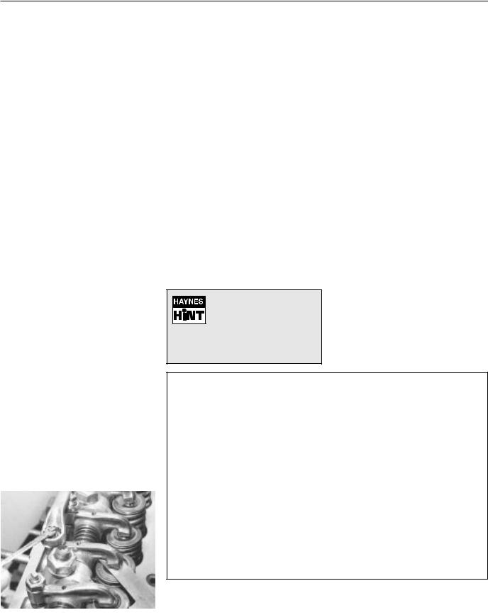
903 cc engine 1•9
Cylinder head - removal and refitting Sump pan - removal and refitting
Pistons/connecting rods - removal and refitting
Oil pump - removal and refitting Engine mountings - renewal
1116 cc and 1301 cc engines
Valve clearances - checking and adjusting Camshaft and camshaft carrier - removal and refitting
Timing belt - removal and refitting Cylinder head - removal and refitting Sump pan - removal and refitting Oil pump - removal and refitting
Pistons/connecting rods - removal and refitting
Engine mountings - renewal
Part 2:
903 cc engine
5 Valve clearances - |
2 |
adjustment |
|
|
|
1Adjust the valves when the engine is cold.
2Unbolt and remove the rocker cover.
3It is important that the clearance is set when the cam follower of the valve being adjusted is on the heel of the cam (ie; opposite the peak). This can be done by carrying out the adjustments in the following order, which also avoids turning the crankshaft more than necessary.
4Turn the crankshaft either using a spanner on the pulley nut or by raising a front roadwheel, engaging a gear (3rd or 4th) and turning the wheel in the forward direction of travel. It will be easier to turn the engine if the spark plugs are first removed.
Valve fully open |
Check and adjust |
||
Valve No. 8 EX |
Valve No. 1 EX |
||
Valve No. 6 IN |
Valve No. 3 IN |
||
Valve No. 4 EX |
Valve No. 5 EX |
||
Valve No. 7 IN |
Valve No. 2 IN |
||
Valve No. 1 |
EX |
Valve No. 8 |
EX |
Valve No. 3 |
IN |
Valve No. 6 |
IN |
Valve No. 5 |
EX |
Valve No. 4 |
EX |
Valve No. 2 |
IN |
Valve No. 7 |
IN |
5Count the valves from the timing cover end of the engine.
6Remember, the inlet and exhaust valve clearances are different.
7Insert the appropriate feeler gauge between the end of the valve stem and the rocker arm. It should be a stiff sliding fit (photo).
8If the clearance is incorrect, release the rocker arm adjuster screw locknut using a ring spanner. Turn the adjuster screw using a small open-ended spanner, but tie something to it in case it is inadvertently dropped through one of the pushrod holes.
9Once the clearance is correct, tighten the locknut without moving the position of the adjuster screw.
10Repeat the operations on the remaining seven valves.
11Re-check all the clearances. Make sure that the rocker cover gasket is in good condition and fit the rocker cover.
6 Timing chain and sprockets |
3 |
- removal and refitting |
|
|
|
1 Remove the alternator drivebelt as described in Chapter 2.
2 Unscrew and remove the crankshaft pulley nut.
To prevent the crankshaft rotating, either select a gear
and have an assistant apply the footbrake hard or
remove the starter motor and lock the ring gear teeth with a large cold chisel or screwdriver.
3 |
Disconnect the hoses from the fuel pump. |
|
4 |
Unbolt and remove the fuel pump with |
|
spacer and rod. |
|
|
5 |
Support the engine on a hoist or under the |
|
sump and disconnect and remove the |
|
|
right-hand mounting. Then unscrew and |
|
|
remove the timing cover bolts. The base of |
|
|
the cover is secured by the front two sump |
|
|
pan studs. Unbolt and lower the front end of |
|
|
the sump. Avoid breaking the gasket. Remove |
|
|
the timing cover. |
|
|
6 |
Undo and remove the camshaft sprocket |
|
securing bolt; this will also release the fuel |
|
|
pump drive cam from the end of the camshaft. |
|
|
Note the timing marks on the camshaft and |
|
|
crankshaft sprockets. |
|
|
7 |
Using two tyre levers, carefully ease the two |
|
sprockets forwards away from the crankcase. |
|
|
Lift away the two sprockets and timing chain. |
|
|
8 |
Remove the Woodruff key from the |
|
crankshaft nose with a pair of pliers and note |
|
|
how the channel in the pulley is designed to fit |
|
|
over it. Place the Woodruff key in a container |
|
|
as it is a very small part and can easily |
|
|
become lost. The camshaft sprocket is |
1 |
|
located on the camshaft by a dowel peg. |
||
Refitting |
|
|
|
||
9 |
Fit the Woodruff key to the front of the |
|
crankshaft.
10Tap the crankshaft sprocket onto the front of the crankshaft.
11Turn the sprocket so that the Woodruff key is uppermost.
12Turn the camshaft until it is in such a position that if the sprocket was fitted the dimple timing mark on the sprocket would be nearest to and in alignment with, the one on the crankshaft sprocket.
|
|
Fig. 1.6 Timing chain and sprockets (Sec 6) |
||||
|
1 |
Sprocket retaining bolt |
4 |
Camshaft sprocket |
7 |
Woodruff key |
|
2 |
Fuel pump eccentric cam |
5 |
Sprocket locating dowel |
8 |
Crankshaft |
5.7 Adjusting a valve clearance |
3 |
Timing chain |
6 |
Camshaft |
9 |
Crankshaft sprocket |
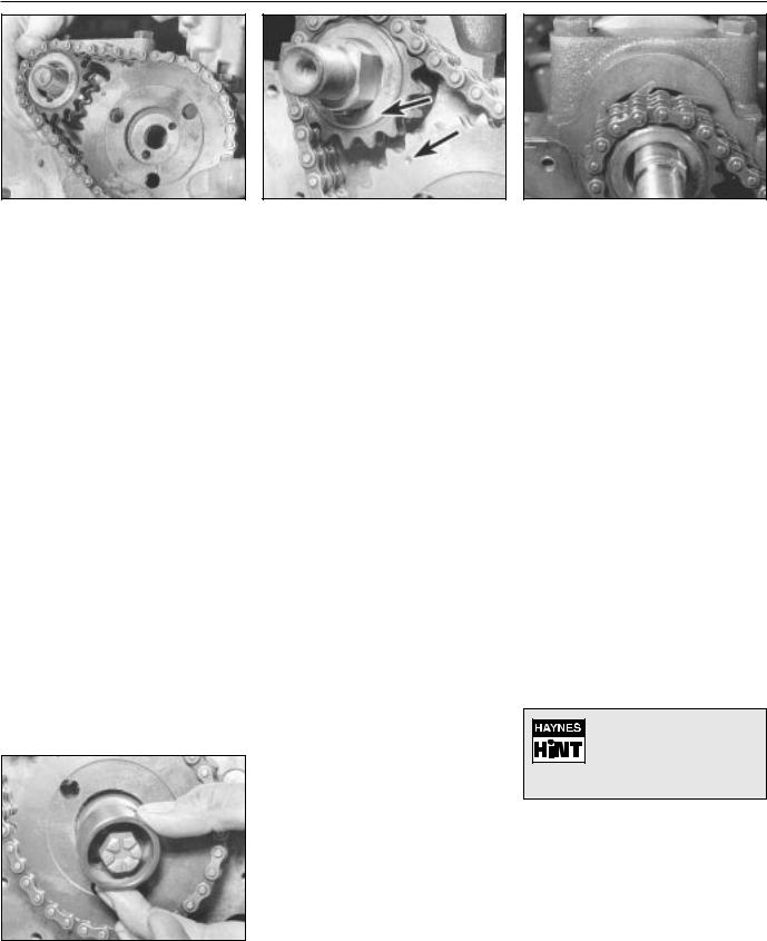
1•10 903 cc engine
chain
13Engage the timing chain with the teeth of the crankshaft sprocket. Then locate the camshaft sprocket within the upper loop of the chain in such a way that when the sprocket is pushed onto the camshaft, the timing marks will be in alignment. Make sure that the self-tensioning links are on the inside of the chain against the cylinder block (photos).
14Place the camshaft sprocket onto the camshaft so that its positioning dowel engages.
15Secure the camshaft sprocket by fitting the special cam, that drives the fuel pump, on its locating dowel. Fit the camshaft sprocket retaining bolt (photo).
16Tighten the sprocket bolt to the specified torque.
17If the timing cover oil seal showed signs of leaking before engine overhaul the old seal should be removed and a new one fitted.
18Using a screwdriver, carefully remove the old oil seal, working from the rear of the cover. Fit the new seal making sure it is inserted squarely, and tap home with a hammer.
19Lubricate the oil seal with engine oil.
20With all traces of old gasket and jointing compound removed from the timing cover and cylinder block mating faces, smear a little grease onto the timing cover mating face and fit a new gasket in position.
21Fit the timing cover to the cylinder block and finger tighten the securing bolts, and spring washer. Ensure that the fuel pump pushrod bush is in place in the cover.
6.15 Fitting fuel pump drive cam and sprocket bolt
22Wipe the hub of the pulley and carefully place into position on the crankshaft. It should locate on the Woodruff key. It may be necessary to adjust the position of the timing cover slightly in order to centralise the oil seal relative to the pulley hub.
23Tighten the timing cover securing bolts in a diagonal and progressive manner.
24Tighten the crankshaft pulley nut to the specified torque again holding the crankshaft against rotation as previously described (paragraph 2) this Section.
25Refit the fuel pump and alternator drivebelt.
7 Cylinder head - |
3 |
|
removal and refitting |
||
|
||
|
|
1For safety reasons, disconnect the battery negative lead.
2Refer to Chapter 2 and drain the cooling system.
3Refer to Chapter 3 and remove the carburettor, air cleaner and spacer block.
4Undo and remove the five nuts and washers securing the exhaust manifold and hot air ducting to the cylinder head.
5Detach the cable from the temperature indicator sender unit.
6Refer to Chapter 4 and disconnect the distributor LT lead and the coil HT lead.
7Refer to Chapter 2 and remove the thermostat housing from the cylinder head.
8Disconnect the coolant hoses from the cylinder head.
9Note the electrical connections to the rear of the alternator and disconnect them.
10Disconnect the mounting and adjuster link bolts and remove the alternator from the engine.
11Unscrew the four nuts securing the rocker cover to the top of the cylinder head and lift away the spring washers and metal packing pieces. Remove the rocker cover and cork gasket.
12Unscrew the four rocker pedestal securing nuts in a progressive manner. Lift away the four nuts and spring washers and
6.13C Self-tensioning links on inside of chain
ease the valve rocker assembly from the cylinder head studs.
13Remove the pushrods, keeping them in the relative order in which they were removed. The easiest way to do this is to push them through a sheet of thick paper or thin card in the correct sequence.
14Unscrew the cylinder head securing bolts half a turn at a time in the reverse order to that shown in Fig. 1.7; don’t forget the one within the inlet manifold. When all the bolts are no longer under tension they may be unscrewed from the cylinder head one at a time. This will also release a section of the cooling system pipe secured by two of the bolts. All the bolts have washers.
15The cylinder head may now be lifted off. If the head is jammed, try to rock it to break the seal. Under no circumstances try to prise it apart from the cylinder block with a screwdriver or cold chisel as damage may be done to the faces of the head or block. If this or the Hint, fail to work, strike the head sharply with a plastic headed hammer, or with a wooden hammer, or with a metal hammer with an interposed piece of wood to cushion the blows. Under no circumstances hit the head directly with a metal hammer as this may cause the casting to fracture. Several sharp taps with the hammer, at the same time pulling upwards, should free the head. Lift the head off and place on one side.
If the head will not readily free, turn the crankshaft. The compression generated in the cylinders will often break the gasket joint
16 The cylinder head may now be decarbonised or dismantled, refer to Section 17.
Refitting
17After checking that both the cylinder block and cylinder head mating surfaces are perfectly clean, generously lubricate each cylinder with engine oil.
18Always use a new cylinder head gasket as the old gasket will be compressed and not capable of giving a good seal.

903 cc engine 1•11
19Never smear grease on the gasket as, when the engine heats up, the grease will melt and may allow compression leaks to develop.
20The cylinder head gasket cannot be fitted incorrectly due to its asymmetrical shape, but the word ALTO should be uppermost in any event (photo).
21The locating dowels should be refitted to the front right and left-hand side cylinder head securing bolt holes.
22Carefully fit the cylinder head gasket to the top of the cylinder block.
23Lower the cylinder head onto the gasket, taking care not to move the position of the gasket.
24Screw in the cylinder head bolts finger tight, remembering the bolt within the intake manifold and the metal coolant pipe which is held by the two cylinder head bolts adjacent to the coolant temperature sender unit (photos).
25Tighten the cylinder head bolts in two stages, in the specified sequence to the torque given in Specifications.
26With the cylinder head in position, fit the pushrods in the same order in which they were removed. Ensure that they locate properly in the stems of the tappets and lubricate the pushrod ends before fitment (photo).
27Unscrew the rocker arm adjuster screws as far as they will go.
28Fit the rocker gear over the four studs in the cylinder head and lower onto the cylinder head. Make sure the ball ends of the rockers locate in the cups of the pushrods.
29Fit the four nuts and washers to the rocker shaft pedestal studs and tighten in a progressive manner to the torque wrench setting given in the Specifications.
30Adjust the valve clearances as described in Section 5.
31Fit the exhaust manifold, thermostat housing and alternator, also the rocker cover (photo).
32Fit the carburettor, air cleaner and distributor (Chapter 4).
33Reconnect all hoses and electrical leads, including the battery.
34Refill the cooling system.
8 Sump pan - |
1 |
|
removal and refitting |
||
|
||
|
|
pipe
|
|
|
|
|
1 |
|
|
|
Fig. 1.7 Cylinder head bolt tightening |
||
sequence (Sec 7) |
|
|
|
|
|
|
|
|
1Drain the engine oil.
2Unscrew and remove the four nuts and twelve bolts and lift away the sump pan. If it has stuck on the gasket carefully tap the side of the mating flange to break the seal. Remove the gasket and clean away any pieces of gasket cement which are adhering to the flanges.
3Remove the sealing strips from the recesses at either end of the sump pan.
Refitting
4 Fit the new sealing strips and if necessary, trim their ends until they are just proud of the sump pan flange (photo).
7.26 Fitting a pushrod
5Using thick grease, stick the gasket side strips to the crankcase.
6Apply a blob of jointing compound at the points of overlap of the side gaskets and strips.
7Offer up the sump pan, screw in and tighten the bolts and nuts progressively (photos).
8Refill the engine with oil.
7.31 Fitting the rocker cover
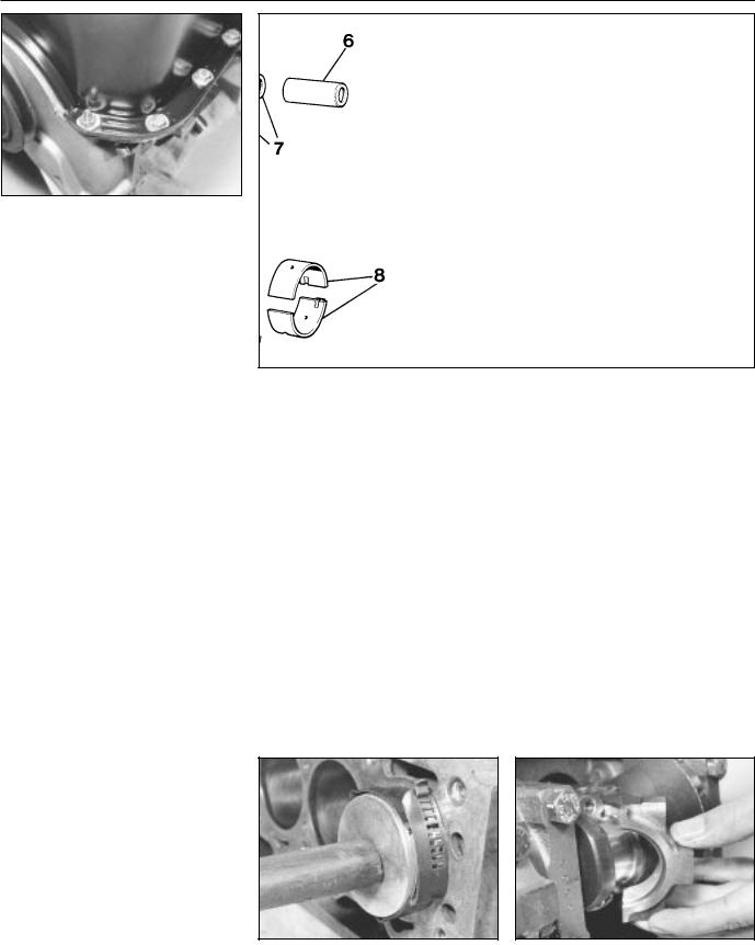
1•12 903 cc engine
9 Pistons/connecting rods - |
3 |
removal and refitting |
|
|
|
1Remove the cylinder head as described in Section 7.
2Remove the sump pan as described in Section 8.
3Undo and remove the big-end cap retaining bolts and keep them in their respective order for correct refitting.
4Check that the connecting rod and big-end bearing cap assemblies are correctly marked. Normally the numbers 1-4 are stamped on adjacent sides of the big-end caps and connecting rods, indicating which cap fits on which rod and which way round the cap fits. The numbers are located on the sides of the rod and cap furthest away from the camshaft.
5If numbers are not evident, then use a sharp file to make mating marks across the rod/cap joint. One line for connecting rod No. 1, two for connecting rod No. 2 and so on. This will ensure that there is no confusion later as it is most important that the caps go back in the correct position on the connecting rods from which they were removed. No. 1 piston should be at the crankshaft pulley end of the engine.
6If the big-end caps are difficult to remove they may be gently tapped with a soft-faced hammer.
7To remove the shell bearings, press the bearing opposite the groove in both the connecting rod and the connecting rod caps and the bearings will slide out easily.
8Keep the shells with their original cap or rod if the bearings are not being renewed.
9Withdraw the pistons and connecting rods upwards and ensure that they are kept in the correct order for replacement in the same bore.
10If the cylinder has a wear ridge at its upper end then this may make it difficult to remove the piston. In this event, relieve the sharp edge of the ridge by scraping.
11Dismantling the pistons is described in Section 18, paragraph 17.
12Lay the piston and connecting rod assemblies in the correct order ready for refitting into their respective bores.
Fig. 1.8 Piston/connecting rod components (Sec 9)
1 |
Bolt |
4 |
Compression ring |
6 |
Gudgeon pin |
2 |
Connecting rod |
|
(stepped at base) |
7 |
Piston gudgeon pins |
3 |
Oil control ring |
5 |
Compression ring |
8 |
Big-end shell bearings |
|
|
|
(marked TOP) |
|
|
13With a wad of clean non-fluffy rag wipe the cylinder bores clean.
14Position the piston rings so that their gaps are 120º apart and then lubricate the rings.
15Wipe clean the connecting rod half of the big-end bearing and the underside of the shell bearing. Fit the shell bearing in position with its locating tongue engaged with the corresponding groove in the connecting rod.
16Fit a piston ring compressor to the top of the piston, making sure it is tight enough to compress the piston rings.
17Using a piece of fine wire double check that the little jet hole in the connecting rod is clean.
18The pistons, complete with connecting rods, are fitted to their bores from above. The number stamped on the connecting rod must face away from the camshaft with the arrow on the piston crown pointing towards the timing cover.
19With the base of the piston ring compressor resting on the cylinder block, apply the wooden handle of a hammer to the piston crown, strike the hammer head with the hand and drive the piston/rod into its bore (photo).
20Draw the rod, complete with shell bearing down onto its crankpin.
21Generously lubricate the crankpin journals with engine oil, and turn the crankshaft so that the crankpin is in the most advantageous position for the connecting rod to be drawn into it.
22Wipe clean the connecting rod bearing cap and back of the shell bearing and fit the shell bearing in position ensuring that the locating tongue at the back of the bearing engages with the locating groove in the connecting rod cap.
23Generously lubricate the shell bearing and offer up the connecting rod bearing cap to the connecting rod (photo).
9.19 Fitting a piston/connecting rod |
9.23 Big-end cap |
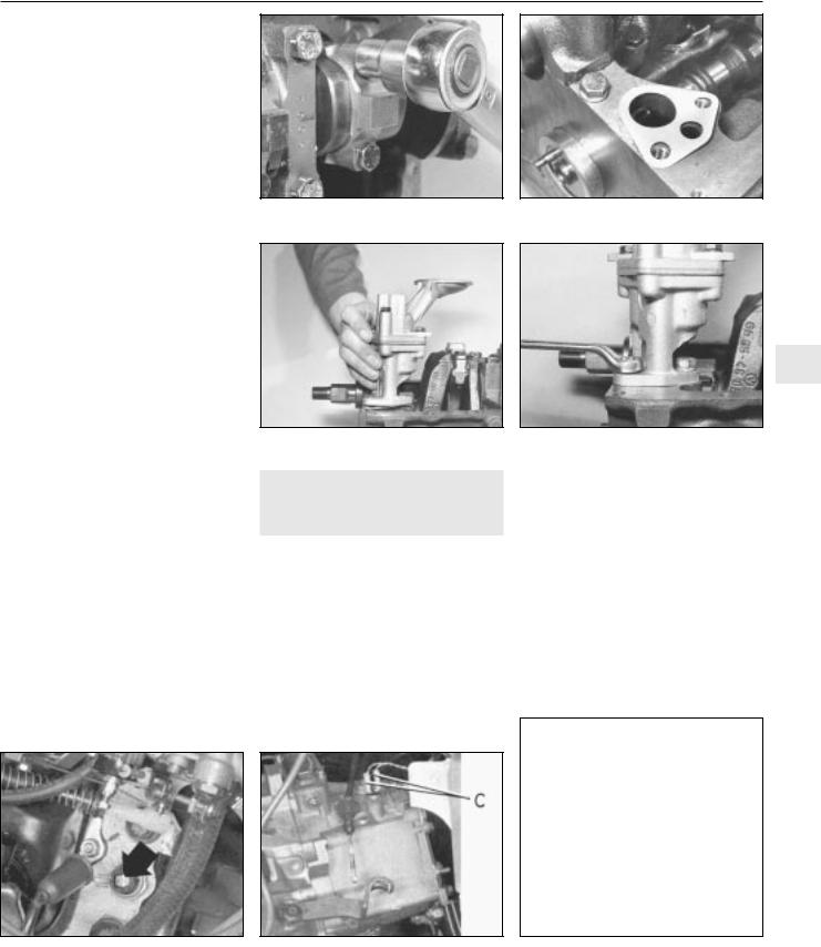
903 cc engine 1•13
24Screw in the big-end bolts and tighten to the specified torque (photo).
25Refit the sump pan (Sec 8) and the cylinder head (Sec 7).
26Refill the engine with oil and coolant.
10 Oil pump - |
1 |
|
removal and refitting |
||
|
||
|
|
1 Remove the sump pan as described in Section 8.
2 Unscrew the two bolts which hold the oil pump housing to the underside of the crankcase and withdraw the pump. Remove and discard the pump flange gasket.
Refitting
3Stick a new gasket to the oil pump location on the underside of the crankcase (photo).
4Locate the oil pump driveshaft in the oil pump and then offer up the complete assembly to the crankcase so that the gear teeth on the driveshaft mesh with those on the camshaft (photo).
5Fit the securing bolts (photo).
6Fit the sump pan and refill the engine with oil.
11 Engine mountings - |
1 |
|
renewal |
||
|
||
|
|
1The engine/transmission flexible mountings can be removed if the power unit is supported under the sump pan or gearbox with a jack, or a hoist is attached to the engine lifting lugs and the weight of the power unit just taken.
2Unscrew the mounting bracket bolts and remove the mounting.
3Fit the new mounting and remove the lifting gear.
4In the unlikely event of all the mountings requiring renewal at the same time, renew them one at a time, never disconnect all the mountings together.
9.24 Tightening a big-end bolt
1
12 Engine - method of removal
1 The engine/transmission should be removed downwards and withdrawn from under the front of the car which will have to be raised sufficiently high to provide clearance.
|
13 Engine/transmission - |
3 |
|
removal and separation |
|
|
|
|
1 |
Open the bonnet, disconnect the |
|
windscreen washer tube. |
|
|
2 |
Mark the hinge positions on the underside |
|
of the bonnet using masking tape and then
with the help of an assistant to support its weight unbolt the bonnet and remove it to a safe place.
3Disconnect the battery negative lead.
4Drain the cooling system and engine oil.
5Disconnect the leads from the rear of the alternator, the starter motor and the oil pressure switch also the coolant temperature switch.
6Disconnect the HT lead from the ignition coil and the LT lead from the distributor. Disconnect the transmission earth strap.
7Remove the air cleaner.
8Disconnect the clutch cable from the release lever at the transmission.
9Disconnect the speedometer drive cable by unscrewing the knurled nut from the transmission.
Fig. 1.9 Coolant temperature switch |
|
Fig. 1.11 Speedometer drive cable at |
(Sec 13) |
C Reversing switch cables |
transmission (Sec 13) |
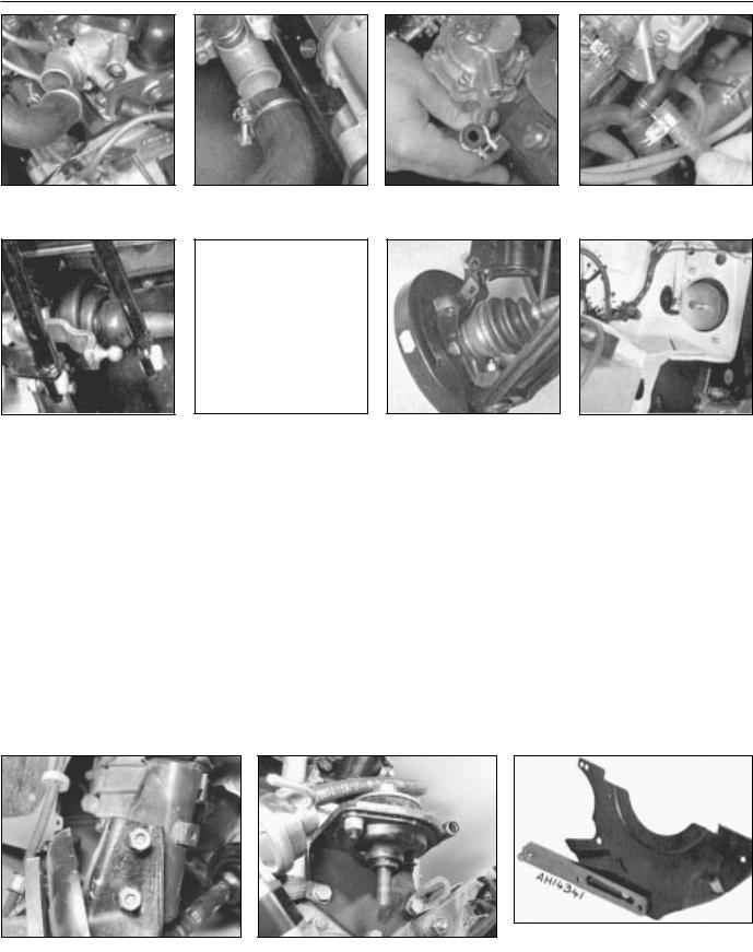
1•14 903 cc engine
Fig. 1.12 Coolant hoses at thermostat housing (Sec 13)
Fig. 1.16 Gearchange rods disconnected (Sec 13)
of coolant pump (Sec 13)
Fig. 1.17 Tie-rod end balljoint disconnected (Sec 13)
Fig. 1.14 Fuel inlet hose disconnected from pump (Sec 13)
Fig. 1.18 Hub carrier detached from strut clamp (Sec 13)
(Sec 13)
Fig. 1.19 Left-hand flexible mounting (Sec 13)
10Disconnect the leads from the reversing lamp switch.
11Disconnect the coolant hoses from the cylinder head and coolant pump.
12Disconnect the fuel inlet hose from the fuel pump. Plug the hose.
13Disconnect the throttle and choke controls from the carburettor.
14Disconnect the heater hoses from the engine.
15Disconnect the fuel return hose from the carburettor.
16Disconnect the exhaust downpipe from the manifold.
17Raise the front end of the car and support it securely on axle stands. Remove the roadwheels.
18Unscrew the driveshaft to hub nuts. These are very tight and a long knuckle bar will be required when unscrewing them. Have an
assistant apply the brakes hard to prevent the hub turning.
19 Working under the car, remove the protective shields and disconnect the exhaust system mountings and withdraw it to the rear.
20 Disconnect the forward ends of the gearchange rods by prising their sockets from the ballstuds.
21Unscrew the nuts on the steering tie-rod end balljoints and using a suitable “splitter” tool separate the balljoints from the steering arms. Unbolt the brake calipers and tie them up out of the way.
22Unscrew and remove the bolts which secure the hub carriers to the U-clamps at the base of the suspension struts (photo).
23Pull the tops of the hub carriers from the clamps and release the driveshafts from the hub carriers.
24Tie the driveshafts in a horizontal plane with lengths of wire.
25Support the engine on a hoist or use a trolley jack under the engine/transmission and remove the bottom mounting and then the upper left and right-hand ones (photo).
26Carefully lower the power unit to the floor and withdraw it from under the car.
27External dirt and grease should now be removed using paraffin and a stiff brush or a water-soluble solvent.
28Unbolt and remove the engine mounting brackets and the starter motor.
29Unbolt and remove the cover plate and gearchange ball stud strut from the lower front face of the flywheel housing.
30With the engine resting squarely on its sump pan unscrew the flywheel housing connecting bolts noting the location of any lifting lugs and hose and wiring brackets.
Fig. 1.20 Flywheel housing cover plate removed (Sec 13)
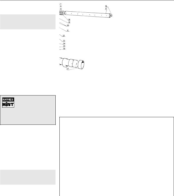
903 cc engine 1•15
31 Support the weight of the transmission and withdraw it in a straight line from the engine.
14 Engine - dismantling (general)
1Stand the engine on a strong bench at a suitable working height. Failing this, it can be dismantled on the floor, but at least stand it on a sheet of hardboard.
2During the dismantling process, the greatest care should be taken to keep the exposed parts free from dirt. As the engine is stripped, clean each part in a bath of paraffin.
3Never immerse parts with oilways in paraffin, e.g. the crankshaft, but to clean, wipe down carefully with a paraffin dampened rag. Oilways can be cleaned out with a piece of wire. If an air line is available, all parts can be blown dry and the oilways blown through as an added precaution.
4Re-use of old gaskets is false economy and can give rise to oil and water leaks, if nothing worse. To avoid the possibility of trouble after the engine has been reassembled always use new gaskets throughout.
Do not throw the old gaskets away as it
sometimes happens that an immediate replacement
cannot be found and the old gasket is then very useful as a template. Hang up the gaskets on a suitable nail or hook as they are removed.
5To strip the engine, it is best to work from the top downwards. The engine oil sump provides a firm base on which the engine can be supported in an upright position. When the stage is reached where the pistons are to be removed, turn the engine on its side. Turn the block upside down to remove the crankshaft.
6Wherever possible, replace nuts, bolts and washers finger-tight from wherever they were removed. This helps avoid later loss and muddle. If they cannot be replaced then lay them out in such a fashion that it is clear from where they came.
15Engine - removing ancillary components
|
|
|
|
|
|
|
|
|
|
|
|
|
|
|
|
|
|
|
1 |
|
Fig. 1.21 Camshaft and rocker gear components (Sec 16) |
||||||||
1 |
Camshaft bush |
8 |
Rocker arm |
17 |
Rocker shaft |
26 |
Inlet valve |
|
|
|
|||||||||
|
lockbolt |
9 |
Thrust washer |
18 |
Coil spring |
27 |
Camshaft bearing |
|
|
2 |
Washer |
10 |
Circlip |
19 |
Stud |
28 |
Camshaft bearing |
|
|
3 |
Camshaft front |
11 |
Locknut |
20 |
Split collets |
29 |
Camshaft |
|
|
|
bearing |
12 |
Washer |
21 |
Spring cap |
30 |
Locating dowel |
|
|
4 |
Exhaust valve |
13 |
Locknut |
22 |
Valve guide |
31 |
Cam follower |
|
|
5 |
Spring cap |
14 |
Pedestal |
23 |
Outer valve spring |
32 |
Pushrod |
|
|
6 |
Valve guide |
15 |
Rocker arm |
24 |
Inner valve spring |
33 |
Washer |
|
|
7 |
Adjuster screw |
16 |
Plug |
25 |
Spring seat |
|
|
|
|
1 Before dismantling the engine, remove the |
|
|
|
|
|
|
|
|
|
engine ancillary components. |
|
|
|
|
|
|
|
|
|
Carburettor (Chapter 3) |
|
|
|
|
|
|
|
|
|
Thermostat housing (Chapter 2) |
|
|
|
|
|
|
|
|
|
|
Fig. 1.22 Cylinder head, block and crankcase (Sec 16) |
||||||||
Alternator (Chapter 9) |
|
||||||||
1 |
Washer |
6 |
Washer |
12 |
Plug |
18 |
Dowel |
||
Coolant pump (Chapter 2) |
|||||||||
Distributor (Chapter 4) |
2 |
Cylinder head bolt |
7 |
Plate |
13 |
Cylinder head bolt |
19 |
Block/crankcase |
|
Exhaust manifold (Chapter 3) |
3 |
Gasket |
8 |
Nut |
14 |
Washer |
20 |
Plug |
|
Fuel pump (Chapter 3) |
4 |
Rocker cover |
9 |
Stud |
15 |
Dowel |
21 |
Plug |
|
Oil filter cartridge (Section 2 this Chapter) |
|
gasket |
10 |
Plug |
16 |
Plug |
22 |
Bolt |
|
Clutch (Chapter 5) |
5 |
Rocker cover |
11 |
Cylinder head |
17 |
Plug |
23 |
Plug |
|
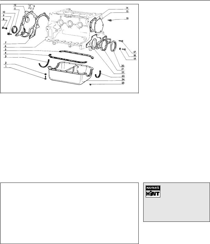
1•16 903 cc engine
|
Fig. 1.23 Timing cover, sump pan and oil seals (Sec 16) |
||||||
|
|
|
|
|
|
|
|
1 |
Sump pan bolt |
8 |
Bolt |
13 |
Fuel pump studs |
20 |
Crankshaft rear oil |
2 |
Washer |
9 |
Washer |
|
and bush |
|
seal |
3 |
Sealing strip |
10 |
Bolt and washer |
15 |
Cover plate |
21 |
Oil seal carrier |
4 |
Side gasket |
11 |
Crankshaft front oil |
16 |
Bolt and washer |
22 |
Gasket |
5 |
Side gasket |
|
seal |
17 |
Bolt |
23 |
Sealing strip |
6 |
Block/crankcase |
12 |
Timing cover |
18 |
Bolt |
24 |
Sump pan |
7 |
Gasket |
14 |
Gasket |
19 |
Washer |
25 |
Drain plug |
16 Engine - |
3 |
complete dismantling |
|
|
|
1Unbolt and remove the rocker cover.
2Unscrew the rocker pedestal securing nuts and lift away the rocker assembly.
3Remove the pushrods, keeping them in their original fitted order.
4Remove the cylinder head as described in Section 7. Remove the dipstick and guide tube.
5Turn the engine on its side and unbolt and remove the sump pan.
6Remove the piston/connecting rods as described in Section 9.
7Unscrew and remove the crankshaft pulley nut. To prevent the crankshaft rotating while this is done, either jam the flywheel ring gear or place a block between a crankshaft counterweight and the inside of the crankcase.
8Unbolt and remove the timing cover.
9Remove the timing chain and sprockets as described in Section 6.
Fig. 1.24 Crankshaft and flywheel (Sec 16)
1 |
Centre main |
3 |
Crankshaft |
6 |
Dowel |
9 |
Bolt |
|
bearing shells |
4 |
Plug |
7 |
Flywheel |
10 |
Thrust washers |
2 |
Front main bearing |
5 |
Starter ring gear |
8 |
Thrust plate |
11 |
Rear main bearing |
|
shells |
|
|
|
|
|
shells |
10 Unbolt and remove the oil pump as described in Section 10.
11Unscrew and remove the camshaft front bearing lockscrew noting that the chamfer on the bearing is on the inboard side.
12Withdraw the camshaft, taking great care not to damage the bearings with the cam lobes.
13Lift out the cam followers and keep them in their originally fitted sequence.
14Unbolt and remove the flywheel. Jam the ring gear teeth to prevent rotation.
15Remove the engine rear plate.
16Turn the cylinder block so that it is standing upside down.
17Unbolt and remove the crankshaft rear oil seal carrier. Note the sump fixing studs.
18The main bearing caps should be marked 1, 2 and 3 but if they are not, centre punch them and note which way round they are located.
19Unscrew the main bearing cap bolts progressively.
20Remove the bearing caps and half shells. If the shell bearings are to be used again, keep them with their respective caps.
21Note the semi-circular thrust washers on either side of the centre main bearing which control crankshaft endfloat.
22Lift the crankshaft from the crankcase.
23Remove the bearing shells from the crankcase and mark them as to position if they are to be used again.
17 Cylinder head - dismantling |
4 |
and decarbonising |
|
|
|
1The exhaust manifold and rocker gear will have been removed from the cylinder head during removal (see Section 7).
2The valves should now be removed using a universal valve spring compressor.
3Compress the first valve spring and extract the split cotters.
If the valve spring refuses to compress, do not apply
excessive force, but remove the compressor and place a
piece of tubing on the spring retainer and strike it a sharp blow to release the collets from the valve stem. Refit the compressor and resume operations when the collets should come out.
4Gently release the compressor, take off the spring retaining cap, the valve spring and the spring seat. Remove the valve. Keep the valve with its associated components together and in numbered sequence so that they can be returned to their original positions.
5A small box with divisions is useful for this purpose. Remove and discard the valve stem oil seals.
6Remove the other valves in a similar way.
7Bearing in mind that the cylinder head is of
 Loading...