


Croma 2009

Dear Customer,
Thank you for selecting Fiat and congratulations on your choice of a Fiat Croma.
We have written this handbook to help you get to know all your new Fiat Croma features and use it in the best possible way.
You should read it right through before taking the road for the first time.
You will find information, tips and important warnings regarding the driving of your car to help you derive the maximum from your
Fiat Croma technological features.
You are recommended to read carefully the warnings and indications, marked with the respective symbols, at the end of the page:
personal safety;
the car’s wellbeing;
environmental protection.
The enclosed Warranty Booklet lists the services that Fiat offers to its Customers:
❒
the Warranty Certificate with terms and conditions for maintaining its validity
❒
the range of additional services available to Fiat Customers.
Best regards and good motoring!
This Owner Handbook describes all Fiat Croma versions. As a consequence, you should consider only
the information which is related to the engine and bodywork version of the car you purchased.

MUST BE READ!
REFUELLING
Petrol engines: only refuel with unleaded petrol with octane rating (RON) not less than 95.
Diesel engines: only refuel with diesel fuel conforming to the European specification EN590.
K
ENGINE STARTING
PARKING ON FLAMMABLE MATERIAL
Using other products or mixtures may damage the engine beyond repair and cause the forfeiture of the warranty cover for caused damages as a consequence.
Petrol engines: make sure that the handbrake is engaged; set the gearshift lever to neutral (positions P or N with
automatic transmission); fully depress the clutch pedal (or brake pedal with automatic transmission) without pressing the accelerator, then turn the ignition key to START and release it as soon as the engine has started.
Diesel engines: make sure that the handbrake is engaged; set the gearshift lever to neutral (positions P or N with
automatic transmission); fully depress the clutch pedal (or brake pedal with automatic transmission) without pressing the accelerator, then turn the ignition key to ON and wait for the Yand mwarning lights to go off; turn the
ignition key to START and release it as soon as the engine has started.
While working, the catalyst develops a very high temperature. Do not park the car over grass, dry leaves, pine needles or any other inflammable materials: risk of fire.
RESPECTING THE ENVIRONMENT
The car is fitted with a system that allows continuous diagnosis of the components correlated with emissions to ensure better respect for the environment.

ELECTRICAL ACCESSORIES
If, after buying the car, you decide to add electrical accessories (that will gradually drain the battery), visit a Fiat
Dealership. They can calculate the overall electrical requirement and check that the car’s electric system can support the required load.
CODE card
Keep the code card in a safe place, not in the car.
SCHEDULED SERVICING
Correct maintenance of the car is essential for ensuring it stays in tip-top condition and safeguards its safety features, its environmental friendliness and low running costs for a long time to come.
쇵
THE OWNER HANDBOOK CONTAINS…
… information, tips and important warnings regarding the safe, correct driving of your car, and its maintenance.
Pay particular attention to the symbols
"
(personal safety) #(environmental protection) ! (the car’s wellbeing).

DDDAASSHHBBOOAARRDDAANNDDCCOONNTTRROOLLS
S
DASHBOARD
AND CONTROLS
SAFETY
DEVICES
OF THE CAR
CORRECT USE
WARNING
MESSAGES
LIGHTS AND
IN AN
EMERGENCY
CAR
MAINTENANCE
TECHNICAL
SPECIFICATIONS
INDEX
INSTRUMENT DASHBOARD........................................... 5
INSTRUMENT PANEL......................................................... 6
SYMBOLS................................................................................ 8
THE FIAT CODE SYSTEM.................................................. 9
THE KEYS ............................................................................... 10
ALARM .................................................................................... 14
DEAD LOCK DEVICE ......................................................... 16
IGNITION DEVICE .............................................................. 19
ON BOARD INSTRUMENTS ............................................ 20
MULTIFUNCTIONAL DISPLAY ...................................... 22
RECONFIGURABLE MULTIFUNCTIONAL DISPLAY .. 25
DISPLAY FUNCTIONS........................................................ 28
TRIP COMPUTER................................................................. 36
SEATS....................................................................................... 39
HEAD RESTS.......................................................................... 42
STEERING WHEEL............................................................... 43
REAR VIEW MIRRORS ....................................................... 44
HEATING/AIR CONDITIONING SYSTEM ................... 47
MANUAL AIR CONDITIONER........................................ 49
AUTOMATIC AIR CONDITIONER................................ 52
EXTERIOR LIGHTS .............................................................. 62
WINDOW CLEANING ...................................................... 65
CRUISE CONTROL ............................................................. 68
CEILING LIGHTS.................................................................. 70
CONTROLS........................................................................... 71
INTERIOR EQUIPMENT..................................................... 74
SUN ROOF............................................................................. 78
DOORS ................................................................................... 81
ELECTRIC WINDOW REGULATORS ........................... 82
BOOT ...................................................................................... 84
ENGINE HOOD ................................................................... 90
ROOF RACK/SKI RACK..................................................... 92
HEADLAMPS.......................................................................... 93
ABS SYSTEM........................................................................... 94
ESP SYSTEM............................................................................ 96
ASR SYSTEM .......................................................................... 97
EOBD SYSTEM ...................................................................... 98
T.P.M.S. SYSTEM.................................................................... 99
CAR RADIO........................................................................... 100
USER PURCHASED ACCESSORIES................................. 101
PARKING SENSORS ............................................................ 102
VEHICLE REFUELLING........................................................ 104
ENVIRONMENTAL PROTECTION................................. 105
4

DASHBOARD
The presence and the position of the instruments and warning lights may vary according to the versions.
fig. 1
F0L0516m
DASHBOARD
AND CONTROLS
SAFETY
DEVICES
OF THE CAR
CORRECT USE
WARNING
MESSAGES
LIGHTS AND
IN AN
EMERGENCY
CAR
MAINTENANCE
TECHNICAL
SPECIFICATIONS
1. Side air vent - 2. Left steering column stalk: external lights - 3. Instrument panel and warning lights - 4. Right steering column
stalk: windscreen, rear window wiper and trip computer controls - 5. Central air vents - 6. Sound system - 7. Front passenger air
bag - 8. Glovebox - 9. Heating/ventilation/climate controls - 10. Gearshift lever - 11. Driver’s knees air bag - 12. Driver’s air bag -
13. Cruise control lever - 14. Control unit access door - 15. Control plate.
INDEX
5
DASHBOARD
AND CONTROLS
SAFETY
DEVICES
OF THE CAR
CORRECT USE
WARNING
MESSAGES
LIGHTS AND
INSTRUMENT PANEL
F0L0504m
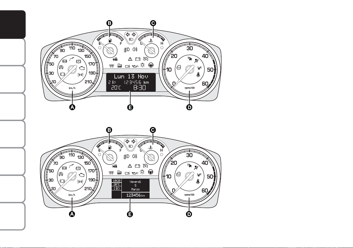
On versions 1.8 the end scale value of the engine speed indicator is 8000 rpm.
1.8 - 1.9 Multijet 8V versions with
multifunctional display
A Speedometer (speed indicator)
B Fuel level gauge with reserve
warning light
C Engine coolant temperature gauge
and excessive temperature warning
light
D Rev counter
E multifunctional display
Warning lights fitted on
c
m
Multijet versions
Warning light fitted on versions
t
with automatic transmission
IN AN
EMERGENCY
CAR
MAINTENANCE
TECHNICAL
SPECIFICATIONS
INDEX
6
F0L0505m
On versions 1.8 the end scale value of the engine speed indicator is 8000 rpm.
fig. 2
1.8 - 1.9 Multijet
8V with
reconfigurable multifunctional display
A Speedometer (speed indicator)
B Fuel level gauge with reserve
warning light
C Engine coolant temperature gauge
and excessive temperature warning
light
D Rev counter
E Reconfigurable multifunctional display
Warning lights fitted on
c
m
Multijet versions
Warning light fitted on versions
t
with automatic transmission
F0L0506m
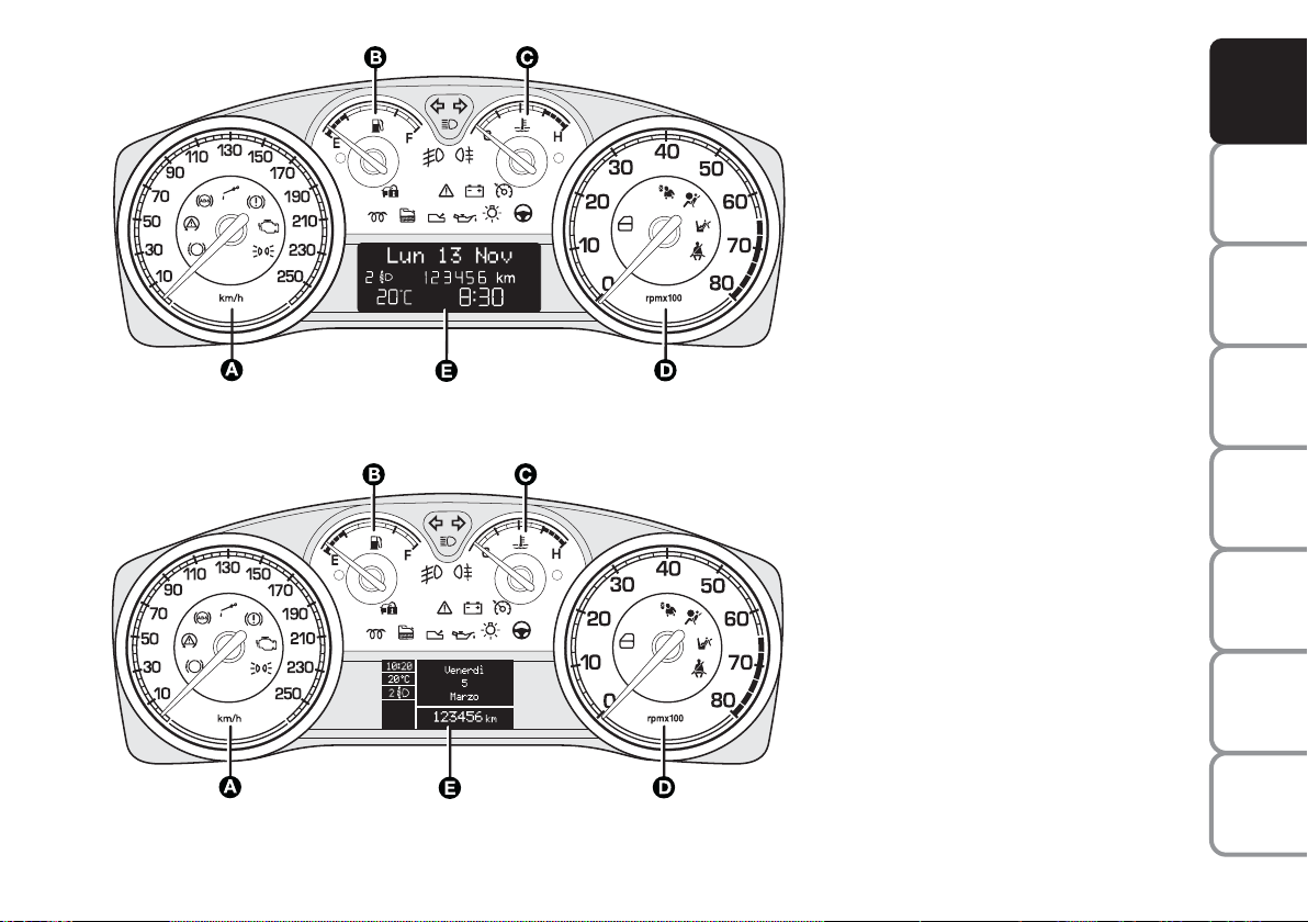
On Multijet versions the end scale value of the engine speed indicator is 6000 rpm.
2.2 - 1.9 Multijet 16V versions -
2.4 Multijet
20V with multifunctional
display
A Speedometer (speed indicator)
B Fuel level gauge with reserve
warning light
C Engine coolant temperature gauge
and excessive temperature warning
light
D Rev counter
E Multifunctional display
Warning lights fitted on
c
m
Multijet versions
Warning light fitted on versions
t
with automatic transmission
DASHBOARD
AND CONTROLS
SAFETY
DEVICES
OF THE CAR
CORRECT USE
WARNING
MESSAGES
LIGHTS AND
F0L0507m
On Multijet versions the end scale value of the engine speed indicator is 6000 rpm.
fig. 3
2.2 - 1.9 Multijet
16V - 2.4 Multijet 20V
with reconfigurable multifunctional
display
A Speedometer (speed indicator)
B Fuel level gauge with reserve
warning light
C Engine coolant temperature gauge
and excessive temperature warning
light
D Rev counter
E Reconfigurable multifunctional display
Warning lights fitted on
c
m
Multijet versions
Warning light fitted on versions
t
with automatic transmission
IN AN
EMERGENCY
CAR
MAINTENANCE
TECHNICAL
SPECIFICATIONS
INDEX
7
DASHBOARD
AND CONTROLS
SAFETY
DEVICES
OF THE CAR
CORRECT USE
WARNING
MESSAGES
LIGHTS AND
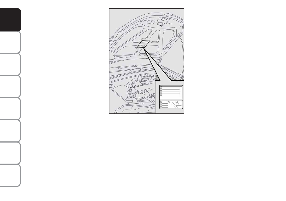
SYMBOLS
Special coloured labels have been attached
near or actually on some of the components of your car. These labels bear symbols that remind you of the precautions
to be taken as regards that particular component.
The plate summarising the symbols used
can be found under the bonnet fig. 4.
IN AN
EMERGENCY
CAR
MAINTENANCE
TECHNICAL
SPECIFICATIONS
INDEX
8
fig. 4
F0L0099m
THE FIAT CODE SYSTEM
To further protect your car from theft, it
has been fitted with an engine immobilising
system. This system is automatically activated when the ignition key is removed.
An electronic device, in fact, is fitted in each
ignition key grip. The device transmits a radio-frequency signal when the engine is
started through a special aerial built into the
ignition switch. The modulate signal, which
changes each time the engine is started, is
the “password”, by means of which the
control unit recognises the key and enables
to start the engine.
OPERATION
Each time the key is fitted into the ignition
switch, the Fiat CODE system control unit
sends a recognition code to the engine control unit to deactivate the inhibitor.
The code is sent only if the Fiat CODE system control unit has recognised the code
transmitted from the key.
Each time the ignition key is removed, the
Fiat CODE system deactivates the functions of the engine electronic control unit.
If the code has not been recognised correctly, the warning light
(where pro-
Y
vided) turns on accompanied by the related message on the display (see chapter
“Warning lights and messages”).
In this case, the key should be removed and
refitted; if the lock continues, possibly try
again with the other key provided with the
car. If it is still not possible to start the car
contact a Fiat Dealership.
IMPORTANT Every key has its own code,
which must be memorised by the system
control unit. To memorise new keys, up to
a maximum of eight, apply to Fiat Dealership.
Warning light
coming on
Y
when driving
❒
If the warning light Yturns on, this
means that the system is running a
self-test (for example for a voltage
drop). At the first stop, turn the ignition key to OFF and then back to
ON: if no failure is detected warning
light Ywill not come on.
❒
If the warning light Ystays on, repeat the procedure described previously leaving the key at OFF for over
30 seconds. Should the inconvenience
persists, contact a Fiat Dealership.
The electronic components inside the key may be damaged
if the key is submitted to sharp
knocks.
DASHBOARD
AND CONTROLS
SAFETY
DEVICES
OF THE CAR
CORRECT USE
WARNING
MESSAGES
LIGHTS AND
IN AN
EMERGENCY
CAR
MAINTENANCE
TECHNICAL
INDEX
9
SPECIFICATIONS
DASHBOARD
AND CONTROLS
SAFETY
DEVICES
OF THE CAR
CORRECT USE
WARNING
MESSAGES
LIGHTS AND
IN AN
EMERGENCY
CAR
MAINTENANCE
THE KEYS
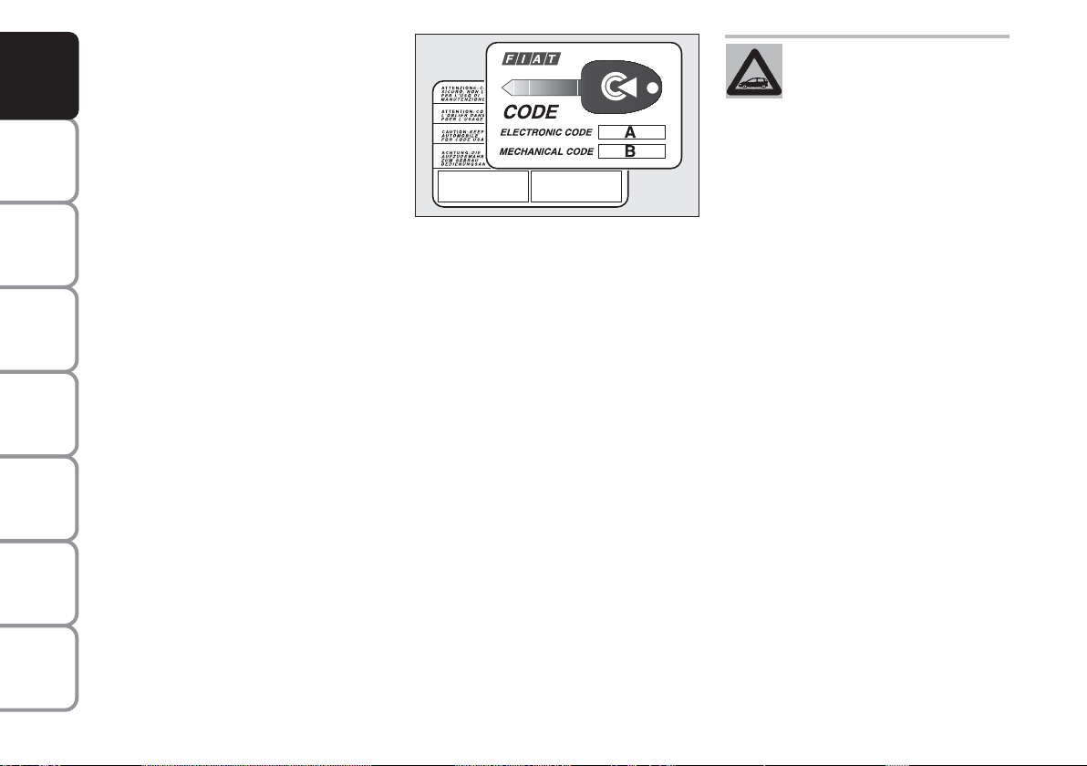
CODE CARD fig. 5
The car is delivered with two copies of the
ignition key and with the CODE card
which bears the following:
❒
the electronic code A
❒
the mechanical key code B to be given to the Fiat Dealership when ordering duplicate keys.
IMPORTANT In order to ensure perfect
efficiency of the electronic devices contained inside the keys, they should never be
exposed to direct sunlight.
fig. 5
All the keys and the CODE
card must be handed over to
the new owner when selling
the car.
F0L0002m
TECHNICAL
SPECIFICATIONS
INDEX
10
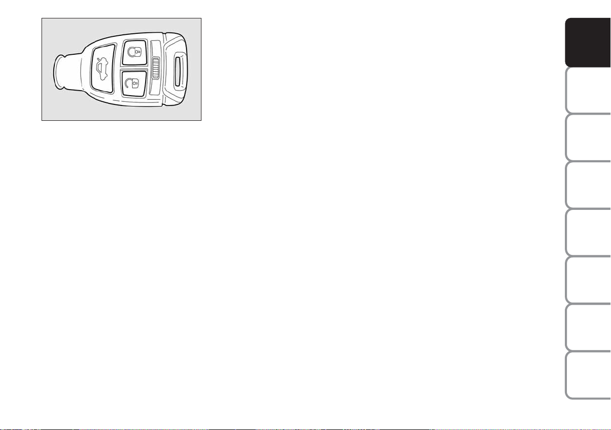
fig. 6
F0L0100m
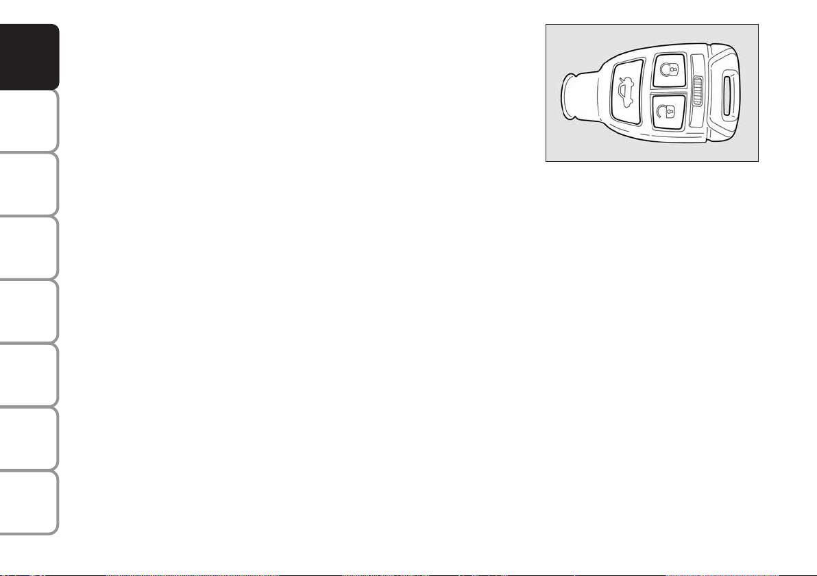
KEY WITH REMOTE CONTROL
fig. 6
This key operates the ignition switch.
Button Ë shall be used for remote open-
ing of doors and tailgate and for remote
deactivation of the alarm (where provided).
Button Á shall be used for remote locking of doors and tailgate and for remote
activation of the alarm (where provided).
Button R shall be used for remote
opening of the tailgate.
When unlocking the doors, the passenger’s compartment lights will come on for
a preset time.
Opening the doors and the tailgate
Briefly press button Ë for remote unlocking of doors, tailgate and fuel filler cap
and simultaneous alarm (where provided)
deactivation, timed switching on of the internal ceiling lights and double flashing of
direction indicators.
Press button Ë for more than 2 seconds
to open the windows.
Doors will be unlocked automatically if the
fuel inertial cut-off switch comes into operation.
The “Set-up menu” on the display (see
paragraph “Multifunction display”) enables
to set the system so that by pressing button Ë, only the driver’s door is unlocked.
In this event, to unlock the other doors
press quickly button Ë twice.
IMPORTANT If the remote control does
not work properly, it is still possible to
carry out the emergency opening procedure by using the metal insert set inside
the remote control (see “Emergency
opening using the metal insert of the key”).
Locking the doors and the tailgate
Briefly press button Á for remote locking of doors, tailgate and fuel filler cap and
simultaneous alarm (where provided) activation, switching off of the internal ceiling lights and single flashing of direction indicators.
Press button Á for more than 2 seconds
to close the windows. If the button is
briefly pressed twice, the dead lock device
is activated (see paragraph “Dead lock device”).
IMPORTANT If the remote control does
not work properly, it is still possible to
lock the car doors by following the procedure described in paragraph “Emergency closing”
DASHBOARD
AND CONTROLS
SAFETY
DEVICES
OF THE CAR
CORRECT USE
WARNING
MESSAGES
LIGHTS AND
IN AN
EMERGENCY
CAR
MAINTENANCE
TECHNICAL
SPECIFICATIONS
11
INDEX
DASHBOARD
AND CONTROLS
SAFETY
DEVICES
OF THE CAR
CORRECT USE
WARNING
MESSAGES
LIGHTS AND
IN AN
EMERGENCY
CAR
MAINTENANCE
TECHNICAL
SPECIFICATIONS
INDEX
Opening the tailgate
by the remote control
Press button Rto open the tailgate by
remote control even if the alarm (where
provided) is on.
Opening the tailgate is accompanied by the
direction indicators flashing twice; closing is accompanied by a single flash (only
if the alarm is on).
If the alarm is on, when the tailgate is
opened the alarm system switches off volumetric protection and the tailgate
perimetral protection sensor.
When closing the tailgate again, volumetric and perimetral protection sensors are
restored.
IMPORTANT If the remote control does
not work properly, it is however possible to open the tailgate through the mechanical lever set on the lock inside the
boot (see paragraph “Boot” in this section).
fig. 7
F0L00382m
LED signals on door lock button
fig. 7
When locking the doors, led A switches
on for about 3 seconds and than starts
flashing (deterrence function).
Once doors are locked, if one or more
doors or the tailgate are not closed correctly, the led and direction indicators
start flashing quickly.
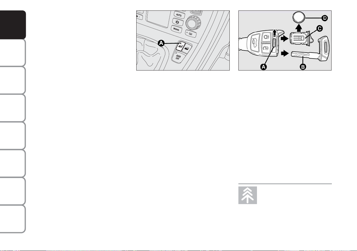
Replacing the battery of the key
with remote control fig. 8
To replace the battery, proceed as follows:
❒
move aside lever A and take out the
emergency metal insert B;
❒
take out the battery case C using the
emergency metal insert, move aside
battery D and replace it making sure
the bias is correct;
❒
refit the battery case C and the emergency metal insert B inside the key.
fig. 8
F0L0101m
Request for additional remote
controls
The system can recognise up to 8 keys with
incorporated remote control. Should a new
key with remote control be necessary, contact a Fiat Dealership, taking with you the
CODE card and the keys, a personal identity document and the car’s ownership documents.
Used batteries are harmful to
the environment. They should
be disposed of as specified by
law in the special containers
provided, or take them to a Fiat Dealership, which will deal with their disposal.
12
DASHBOARD
AND CONTROLS
SAFETY
DEVICES
fig. 9
F0L0103m
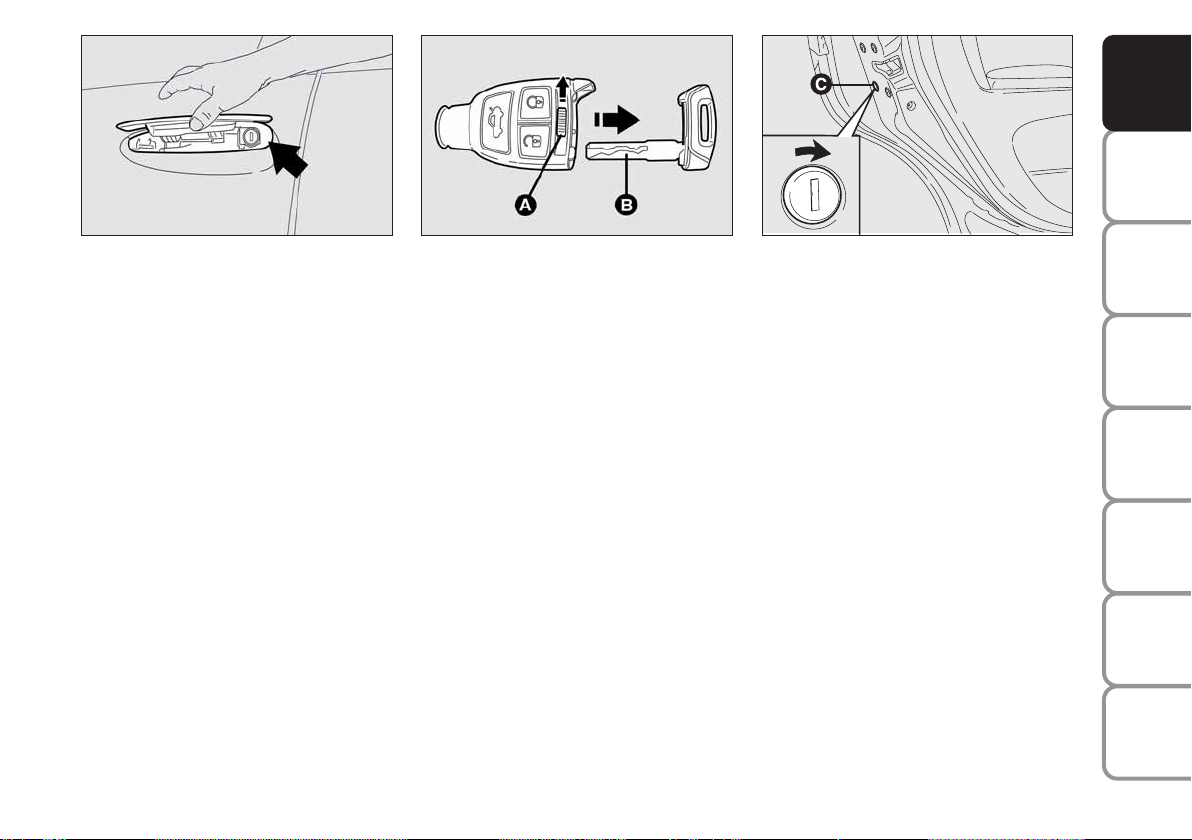
EMERGENCY OPENING USING
THE METAL INSERT
If the remote control does not work
properly (e.g.: battery flat), it is however
possible to use the emergency metal insert set inside the remote control.
The metal insert operates the driver’s side
lock (the pawl is located under the outdoor handle fig. 9).
To use the metal insert set inside the remote control, proceed as follows fig. 10:
❒
move aside lever A and take out the
emergency metal insert B, at the same
time.
fig. 10
F0L0102m
The metal insert acts on the interested
door.
For emergency opening proceed as follows:
❒
raise the handle, fit the metal insert into the revolving plug and turn it counterclockwise;
❒
remove the key and lower the handle;
❒
raise the handle and open the door.
fig. 11
F0L0205m
EMERGENCY CLOSING
fig. 11
To lock the doors if the remote control
does not work properly, proceed as follows:
❒
fit the metal insert into the slot C set
on the doors and turn it in the direction of the arrow (as shown in the figure).
IMPORTANT Before carrying out the
emergency door locking, check whether
the independent boot locking function on
the multifunction display set-up menu is
off (see paragraph “Multifunction display”).
OF THE CAR
CORRECT USE
WARNING
LIGHTS AND
IN AN
EMERGENCY
CAR
MAINTENANCE
TECHNICAL
SPECIFICATIONS
INDEX
13
MESSAGES
DASHBOARD
AND CONTROLS
SAFETY
DEVICES
OF THE CAR
CORRECT USE
WARNING
MESSAGES
LIGHTS AND
IN AN
EMERGENCY
CAR
MAINTENANCE
TECHNICAL
SPECIFICATIONS
INDEX
ALARM
(where provided)
WHEN THE ALARM
IS TRIGGERED
The alarm comes into action in the following cases:
❒
unlawful opening of one of the doors,
bonnet or boot (perimetral protection);
❒
attempt to start the engine with unauthorised key;
❒
battery cable cutting;
❒
presence of moving bodies in the passenger’s compartment (volumetric
protection);
❒
abnormal raising/sloping of the car.
Depending on the markets, the cutting in
of the alarm causes operation of the siren
and direction indicators (for about 26 seconds). The ways of operating and the number of cycles may vary depending on the
markets.
A maximum number of sound/sight cycles
is however envisaged.
Volumetric and anti-raising protections
can be cut off by operating the front ceiling light controls (see paragraphs “Volumetric protection sensors” and “Anti-raising sensor” on the following pages).
IMPORTANT The engine immobiliser
function is guaranteed by the Fiat CODE
system, which is automatically activated
when the ignition key is removed.
HOW TO ACTIVATE
THE ALARM fig. 12
With the doors, bonnet and boot shut and
ignition key to OFF or removed, point
the key with remote control or removed,
point the key with remote control in the
direction of the car, then press and release
the button
Á.
With the exception of certain markets,
the system sounds a “beep” and the doors
are locked.
Engagement of the alarm is preceded by
a self-diagnostic test. If a fault is detected
the system sounds a further warning
“beep” and the display shows the relevant
message (see section “Warning lights and
messages”).
In this case, switch the alarm system off by
pressing button Ë, check that the doors,
bonnet and tailgate are properly shut, then
switch the system on again by pressing
button Á.
fig. 12
F0L0100m
If the doors, bonnet and boot are shut
correctly and the warning “beep” is repeated, the system self-diagnostics has detected a system operating fault. It is therefore necessary to contact a Fiat Dealership.
IMPORTANT Operating a door with the
metal insert of the key will not activate the
alarm.
IMPORTANT The alarm is built in compliance with the law and regulations of the
different destination countries.
14
HOW TO DEACTIVATE
THE ALARM fig. 12
Press button
Ë
of the key with remote
control.
The system will react as follows (with the
exception of certain markets):
❒
two brief flashes of the direction indicators;
❒
two brief “beeps”;
❒
door unlocking.
IMPORTANT Operating a door with the
metal insert of the key will not activate the
alarm.
To deactivate the alarm, turn the ignition
key to ON.
fig. 13
F0L0171m
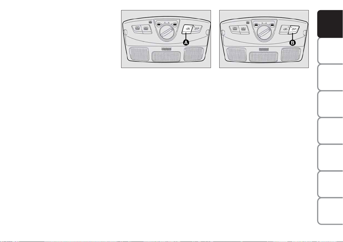
VOLUMETRIC PROTECTION
SENSORS
The volumetric sensors are located inside
the front ceiling light in the passenger’s
compartment. To make sure that the volumetric sensors are working properly,
check that doors, boot, bonnet, windows
and sunroof (where provided) are shut.
Anti-raising protection
deactivation
If it is necessary to switch on the alarm
when animals or people are in the car,
press button A-fig. 13 on the front ceiling light to deactivate the volumetric protection.
Deactivation is needed also in the presence of additional independent heater and
when it is switched on with the remote
control.
fig. 14
F0L0172m
ANTI-RAISING SENSOR
The anti-raising sensor detects any abnormal car raising/sloping, even partial
(e.g.: attempt to remove a wheel).
This sensor can detect the smallest car
sideslip angle changes, both longitudinally
and transversally. Sideslip angle changes
lower than 0.5°/min. (e.g.: slow tyre flattening) are not considered).
Anti-raising protection
deactivation
To deactivate the anti-raising protection
(for example when towing the car with
alarm on) press button B-fig. 14 on the
front ceiling light. Sensor cut-out stays on
until activating the central door opening
again.
DASHBOARD
AND CONTROLS
SAFETY
DEVICES
OF THE CAR
CORRECT USE
WARNING
MESSAGES
LIGHTS AND
IN AN
EMERGENCY
CAR
MAINTENANCE
TECHNICAL
SPECIFICATIONS
INDEX
15
DASHBOARD
AND CONTROLS
SAFETY
DEVICES
OF THE CAR
CORRECT USE
WARNING
MESSAGES
LIGHTS AND
IN AN
EMERGENCY
CAR
MAINTENANCE
TECHNICAL
SPECIFICATIONS
INDICATIONS OF ATTEMPTS
TO BREAK IN
Any attempt to break in is indicated by
turning on of warning light
Y
(if provided) on the instrument panel with the
relevant message on the display (see section “Warning lights and messages”).
HOW TO CUT OFF THE ALARM
SYSTEM
To deactivate the alarm system completely (for instance during prolonged inactivity of the car) simply lock the car using the emergency locking.
IMPORTANT To cut-out the alarm if remote control batteries are down or the
system is failing, fit the key into the ignition switch and turn it to ON.
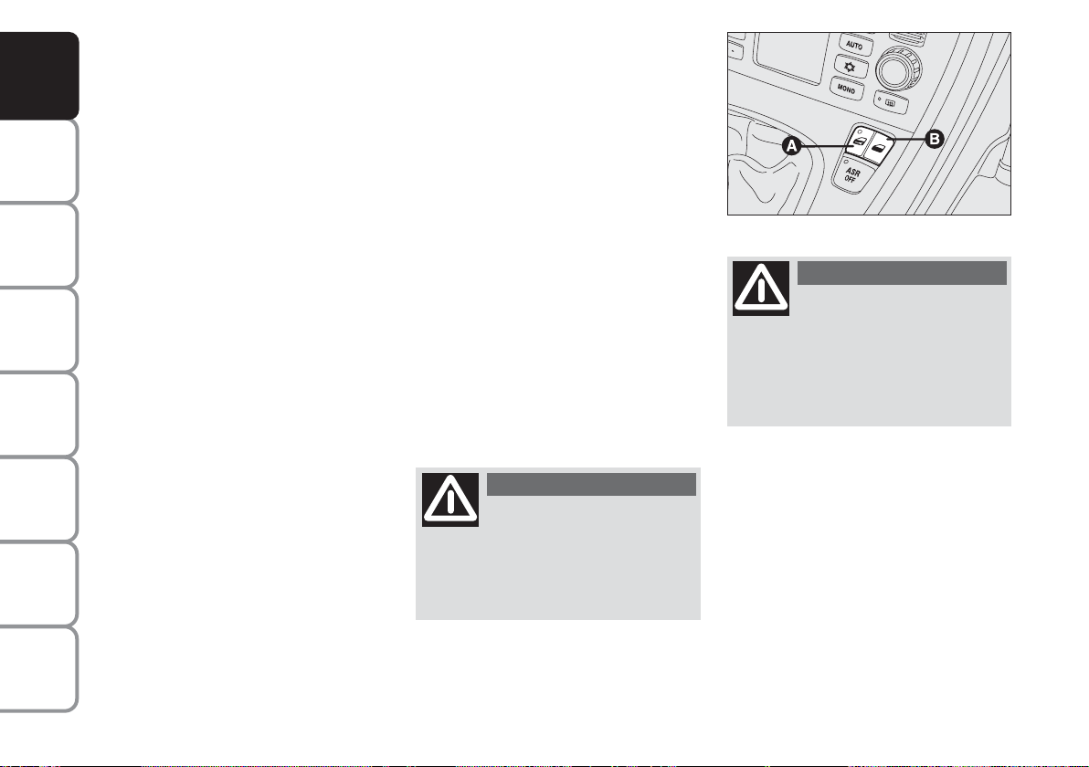
DEAD LOCK DEVICE
(where provided)
This safety device enables to inhibit:
❒
door internal handles;
❒
button A and B for locking/unlocking
the doors fig. 15;
thus hindering doors opening from inside
the passenger’s compartment in case of
attempt to break-into (e.g. window breaking).
The dead lock device guarantees the best
protection against unwanted access.
Therefore, it should be actuated every
time the car is parked and left unattended.
WARNING
Once the dead lock device
has been actuated, doors
cannot be opened from inside the car
in any way whatsoever. For this reason, make sure there are no persons
left inside the car.
fig. 15
F0L0003m
WARNING
If the battery of the key with
remote control is down, the
dead lock device can be activated only using the metal insert of the key on
the driver’s side door as described previously: in this case the dead lock device is active only on the rear doors.
INDEX
16
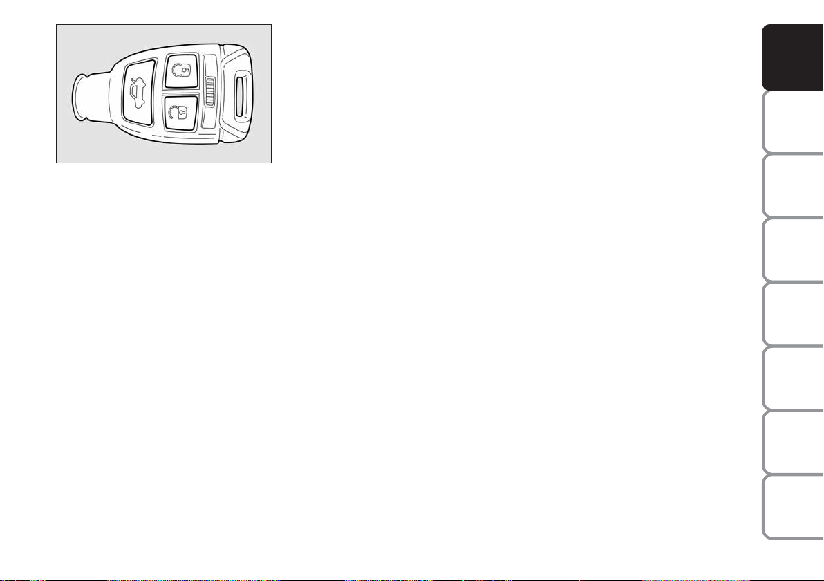
fig. 16
F0L0100m
Device activation is signalled by three
flashes of the direction indicators and
flashing of the led on the driver door panel (see the table on next page).
Should one of the doors be not perfectly
closed, the dead lock device is not activated, thus preventing that a person getting into the car from the open door remains blocked inside the passenger’s compartment when he/she closes the door.
Device deactivation
The device is deactivated automatically on
every door in the following cases:
❒
when unlocking the doors by the remote control;
❒
when unlocking only the driver’s door
by the remote control;
❒
when turning the ignition key to ON.
DASHBOARD
AND CONTROLS
SAFETY
DEVICES
Device activation fig. 16
The device is automatically activated on
every door in the following cases:
❒ pressing twice button
Á
of the key
with remote control
OF THE CAR
CORRECT USE
WARNING
LIGHTS AND
IN AN
EMERGENCY
CAR
MAINTENANCE
TECHNICAL
SPECIFICATIONS
INDEX
17
MESSAGES

The main functions that can be activated with the keys or with the emergency metals insert are the following:
DASHBOARD
AND CONTROLS
SAFETY
DEVICES
OF THE CAR
CORRECT USE
WARNING
MESSAGES
LIGHTS AND
IN AN
EMERGENCY
CAR
MAINTENANCE
TECHNICAL
SPECIFICATIONS
Tailgate
opening
Pressing on
button R
–
2 flashings
–
Key with
remote control
Emergency
metal
insert
Direction
indicators
flashing (only
with key with
remote control)
LED on door lock
button
Door opening
and fuel
filler cap
unlocking
Press briefly
button
Ë
Turn the key in a
counter clockwise
direction
(driver's side)
2 flashings
Turning off
deterrence led
Door closing
and fuel
filler cap
locking
Pressing briefly
button Á
Turn the key
in a clockwise
direction
(driver's side)
1 flashing
Turning on fixed
for about 3
seconds, followed
by deterrence
led flashing
Window
opening
Prolonged
pressing
(over 2 seconds)
on button Ë
–
2 flashings
Turning off
deterrence led
Window
closing
Prolonged
pressing
(over 2 seconds)
on button Á
–
1 flashing
Deterrence led
flashing
Dead lock
(where
provided)
Double pressing
on button Á
–
3 flashings
Double flashing,
followed by
deterrence led
flashing
IMPORTANT The emergency metal insert will unlock only the door.
IMPORTANT Window opening operation is a consequence of a door unlocking control; window closing operation is a consequence
of a door locking control.
INDEX
18
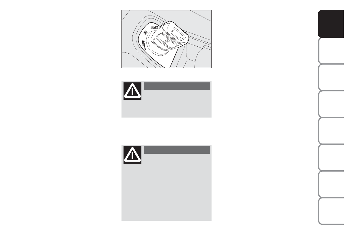
IGNITION SWITCH
STEERING COLUMN LOCK
The key can be turned to 3 different positions fig. 17:
❒
OFF: engine off, key can be removed,
steering column locked. Certain electrical devices (e.g.: sound system, power windows…) can work.
❒
ON: driving position. All electrical devices are powered.
❒
START: engine starting.
The ignition switch is fitted with an electronic safety system that, in the event the
engine is not started, turns back the ignition key to OFF before repeating the
starting operation.
fig. 17
F0L0004m
WARNING
If the ignition device is tam-
pered with (e.g.: attempted
theft), have it checked over by a Fiat
Dealership as soon as possible.
WARNING
When getting out of the car,
always remove the key to
prevent any occupants from accidentally activating the controls. Remember to engage the handbrake
and if the car is parked on uphill slope
to engage the first gear. If the car is
facing downhill, engage the reverse
gear (position P with automatic transmission). Never leave unsupervised
children in the car.
Engaging
The steering column lock will engage 5
seconds after removing the key from the
ignition switch (engine off).
Disengaging
The steering column lock will disengage
after fitting the key into the ignition switch.
IMPORTANT Switching the engine off
when the car is running will not engage the
steering column lock. The multifunction
display will show the relevant message
(see section “Warning lights and Messages”).
IMPORTANT If, after trying to turn the
instrument panel on and/or to start the
engine, the display will show the message
“Check vehicle protection system”, repeat
the operation rocking the steering wheel
to facilitate steering unlocking. Displaying
of this message does not impair steering
column lock operation.
IMPORTANT When the vehicle is moving, the electronic key must remain in the
ignition device. That ensures that the steering lock is disabled during vehicle handling (e.g., when the vehicle is towed).
DASHBOARD
AND CONTROLS
SAFETY
DEVICES
OF THE CAR
CORRECT USE
WARNING
MESSAGES
LIGHTS AND
IN AN
EMERGENCY
CAR
MAINTENANCE
TECHNICAL
SPECIFICATIONS
INDEX
19
DASHBOARD
AND CONTROLS
SAFETY
DEVICES
OF THE CAR
CORRECT USE
WARNING
MESSAGES
LIGHTS AND
IN AN
EMERGENCY
CAR
MAINTENANCE
WARNING
It is absolutely forbidden to
carry out whatever aftermarket operation involving steering
system or steering column modifications (e.g.: installation of anti-theft
device) that could badly affect performance and safety, cause the lapse
of warranty and also result in noncompliance of the car with homologation requirements.
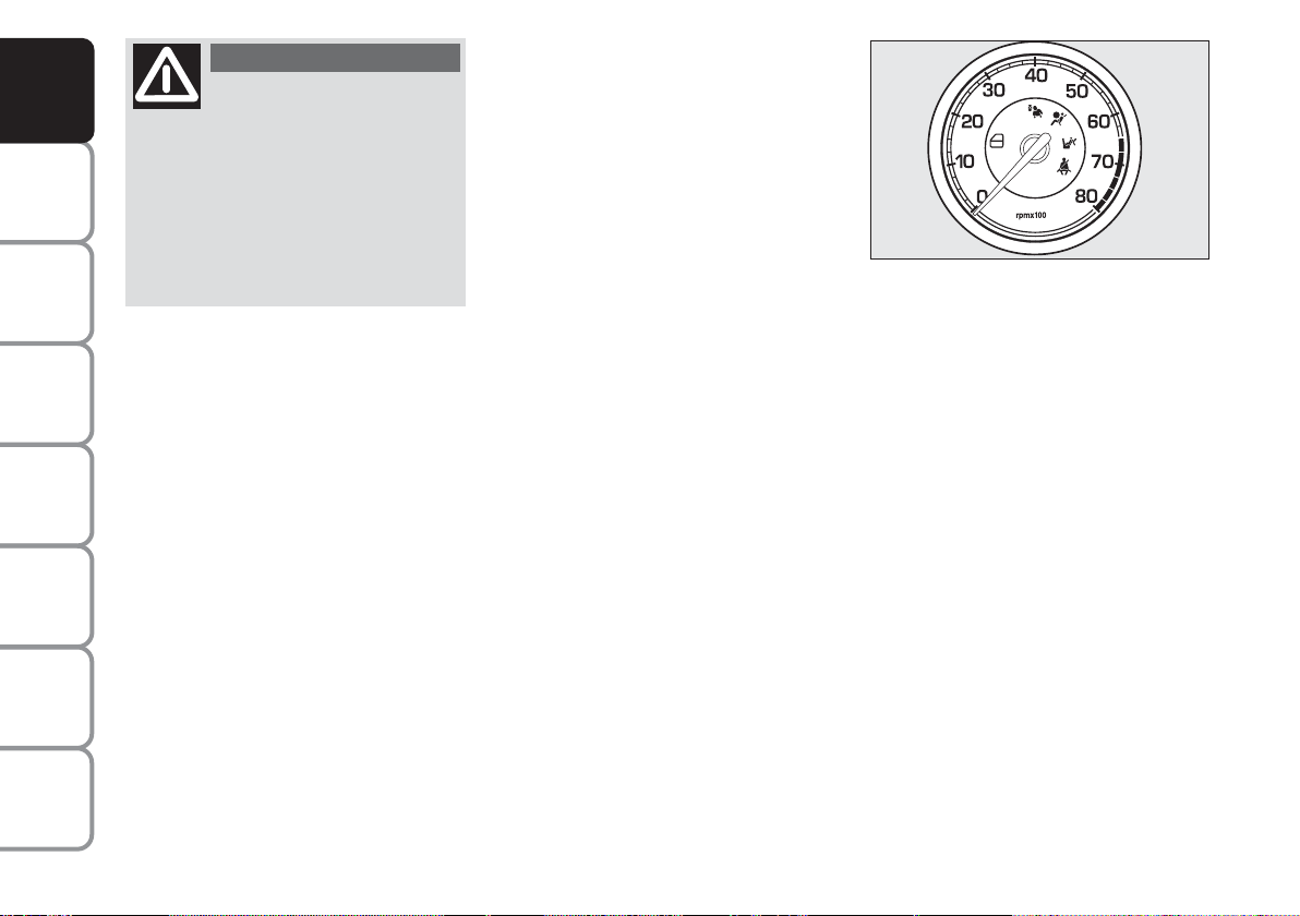
INSTRUMENTS
REV. COUNTER fig. 18
Rev counter shows engine rpm.
The rev. counter end of scale values can
vary based on the version.
IMPORTANT The electronic injection
control system gradually shuts off the flow
of fuel when the engine is “over-revving”
resulting in a gradual loss of engine power.
fig. 18
FF0L0512m
When the engine is idling, the rev counter
may indicate a gradual or sudden highering of the speed.
This is normal as it takes place during normal operation, for example when activating the climate control system or the fan.
In particular a slow change in the speed
preserves the battery charge.
TECHNICAL
SPECIFICATIONS
INDEX
20
DASHBOARD
km/h
AND CONTROLS
SAFETY
DEVICES
fig. 19
FF0L0513m
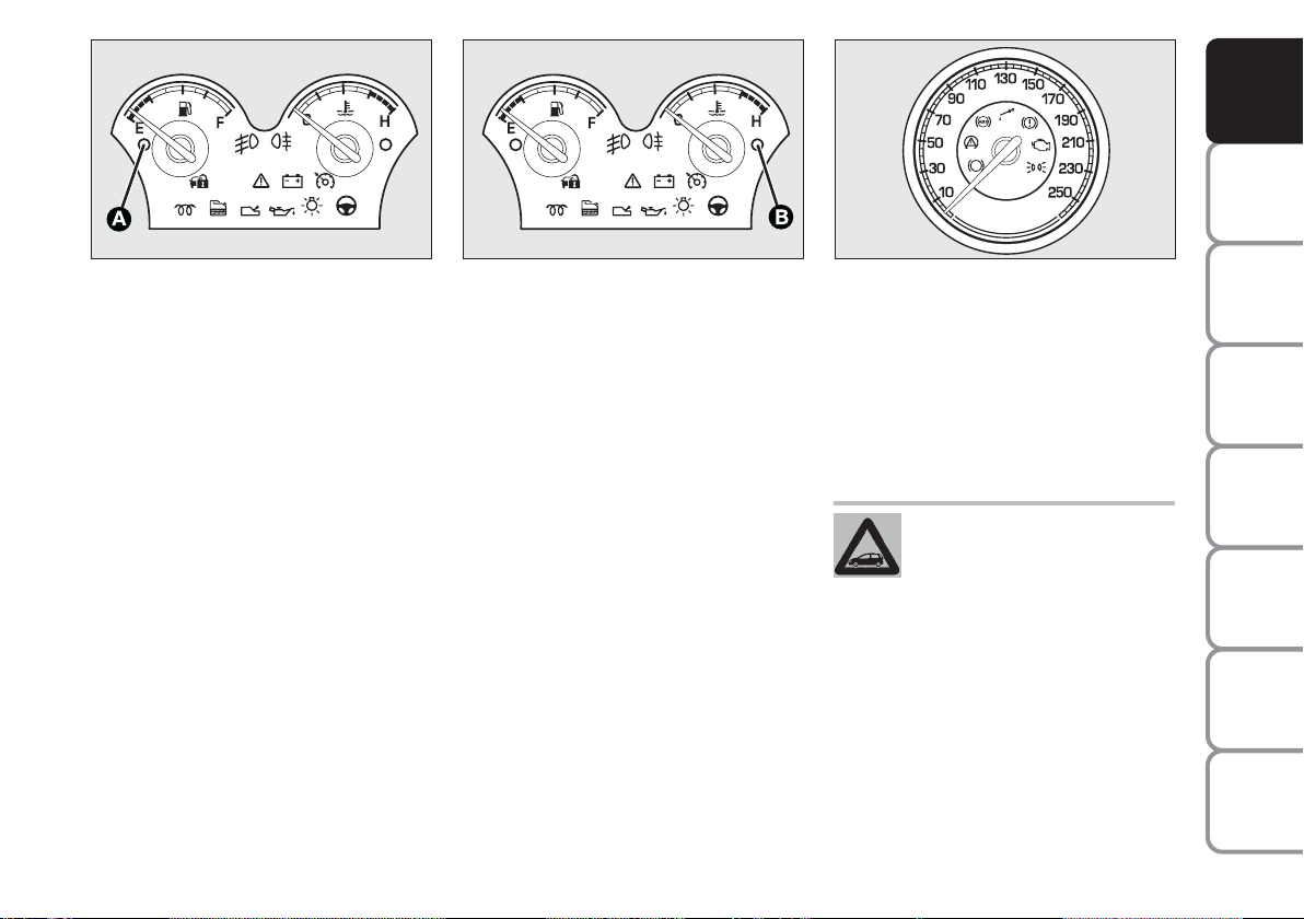
FUEL LEVEL GAUGE fig. 19
This shows the amount of fuel left in the
fuel tank.
The reserve warning light A turns on to
indicate that approx. 7 to 9 litres of fuel
are left in the tank.
E - tank empty.
F - tank full (see the indications given in
paragraph “At the filling station").
Do not travel with the fuel tank almost
empty: the gaps in fuel delivery could damage the catalyst.
fig. 20
F0L0514m
ENGINE COOLANT
TEMPERATURE GAUGE fig. 20
The turning on of the warning light B in-
dicates that the coolant fluid temperature
is too high; in this case, stop the engine
and contact a Fiat Dealership.
This shows the temperature of the engine
coolant fluid and begins working when the
fluid temperature exceeds approx. 50°C.
Under normal conditions, the needle
should move to different positions of the
scale according to the working conditions
and engine cooling conditions.
fig. 21
F0L0515m
IMPORTANT If the needle sets at the bottom of the scale (low temperature) with
warning light B on, it means that the system is malfunctioning. Contact a Fiat Dealership to have the system inspected.
If the needle reaches the red
area, stop the engine immediately and contact a Fiat Dealership.
SPEEDOMETER fig. 21
It shows the engine speed.
The speed indicator end of scale values
can vary based on the version.
OF THE CAR
CORRECT USE
WARNING
LIGHTS AND
IN AN
EMERGENCY
CAR
MAINTENANCE
TECHNICAL
SPECIFICATIONS
INDEX
21
MESSAGES
DASHBOARD
AND CONTROLS
SAFETY
DEVICES
OF THE CAR
CORRECT USE
WARNING
MESSAGES
LIGHTS AND
IN AN
EMERGENCY
CAR
MAINTENANCE
MULTIFUNCTION
DISPLAY
(where provided)
The vehicle may have a multifunctional display that provides the user with useful information, based on what was previously
set, while driving.
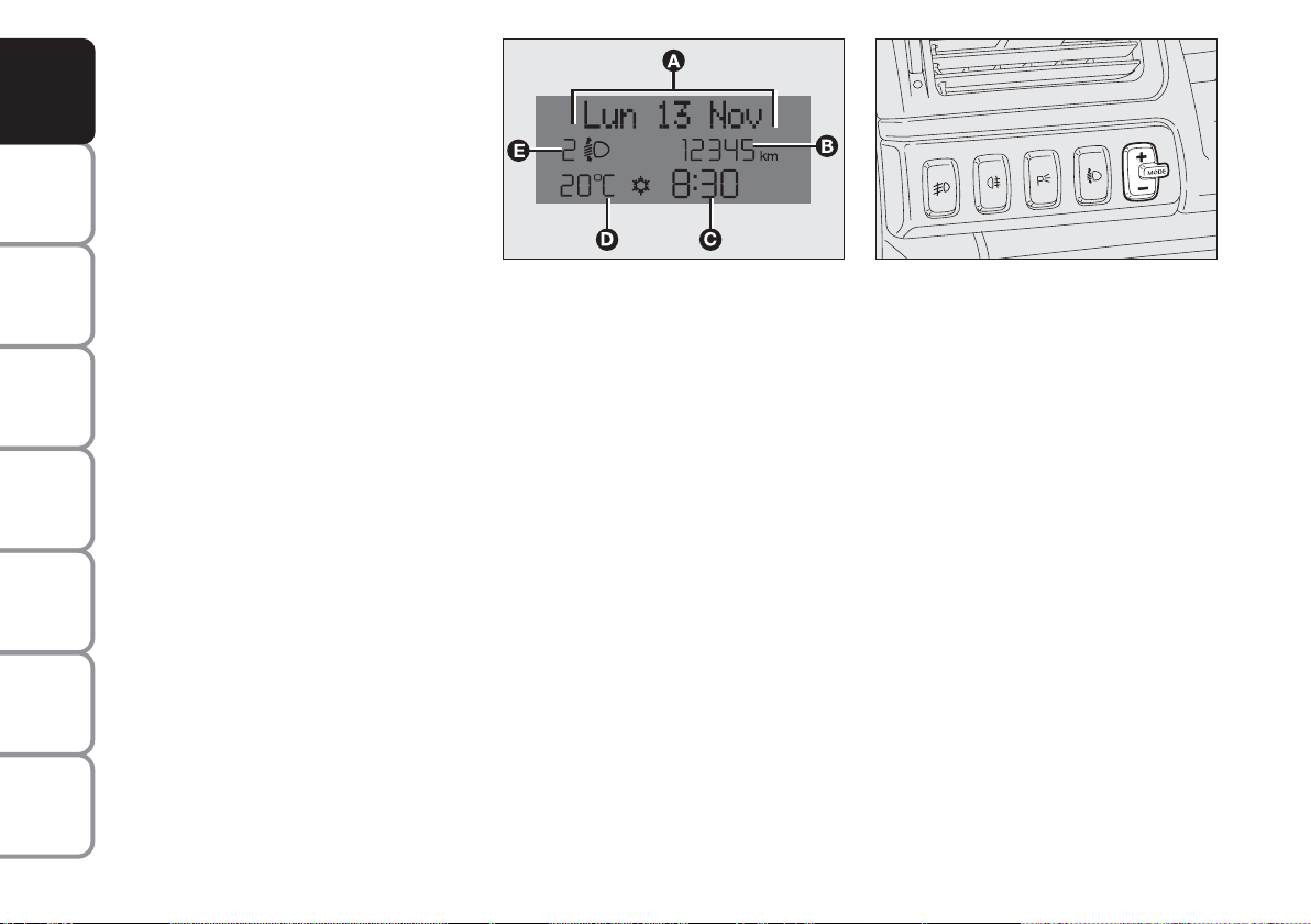
“STANDARD” SCREEN fig. 22
The standard screen shows the following
indications:
A Date
B Odometer (covered km or miles)
C Clock
D External temperature
E Headlight aiming position (only with
dipped beam headlights on).
Note When opening one of the front
doors, the display will turn on and show
for a few seconds the clock and the km or
mi covered.
fig. 22
F0L0071m
CONTROL BUTTONS fig. 23
+ To scroll the displayed menu and the
related options upwards or to increase
the value displayed.
MODE Brief press to open the menu
and/or to move to next screen
or to confirm the option required.
Long press to go back to the
standard screen.
– To scroll the displayed menu and the
related options downwards or to decrease the value displayed.
fig. 23
F0L0029m
Note Buttons + and – activate different
functions according to the following situations:
To adjust light inside the passenger
compartment
– to adjust instrument panel, sound system and automatic climate control system
display brightness when standard screen
is active.
Setup menu
– to scroll the menu options upwards and
downwards;
– to increase or decrease values during settings.
TECHNICAL
SPECIFICATIONS
INDEX
22

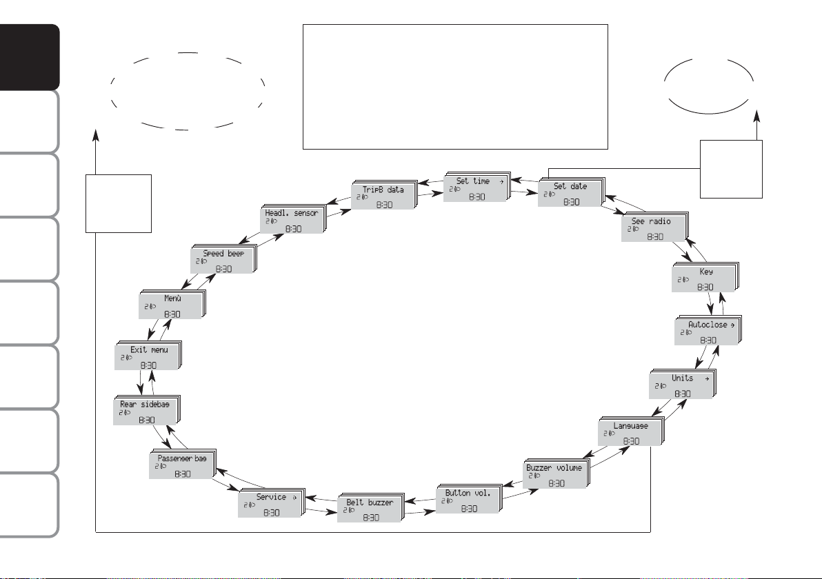
SETUP MENU fig. 24
The menu comprises a series of functions
arranged in a “circular fashion” which can
be selected through buttons + and – to
access the different select operations and
settings (setup) given in the following paragraphs.
The setup menu can be activated by pressing briefly button MODE, only with the
car turned on (with car off, only the reduced menu can be displayed).
Single presses on buttons + or – will scroll
the setup menu options.
Handling modes differ with each other according to the characteristic of the option
selected.
NOTE If the car is equipped with the Radionavigation System, the only functions
that can be adjusted/set through the instrument panel display are the following:
“Speed limit”, “Automatic headlight daylight sensor” (where provided) and “S.B.R.
(Seat Belt Reminder) buzzer reactivation”
(where provided). The other functions are
displayed by and can be adjusted/set
through the Radionavigation System display.
Selecting a menu option
– press briefly button MODE to select
the menu option to set;
– press buttons + or – (by single presses) to select the new setting;
– press briefly button MODE to store the
new setting and to go back to the previously selected menu option.
Selecting “Date” and “Set Clock”:
– briefly press button MODE to select
the first value to change (e.g. hours /minutes or year / month / day);
– press buttons + or – (by single presses) to select the new setting;
– briefly press button MODE to store the
new setting and to go to the next setup
menu option, if this is the last one you will
go back to the previously selected option of
the main menu.
Press button MODE for long:
– to quit the setup menu and to save only the settings stored yet by the user (and
confirmed by pressing briefly button
MODE).
The setup menu displaying is timed; when
quitting the menu due to timing expiry,
only settings stored yet by the user (and
confirmed by pressing briefly button
MODE) will be saved.
DASHBOARD
AND CONTROLS
SAFETY
DEVICES
OF THE CAR
CORRECT USE
WARNING
MESSAGES
LIGHTS AND
IN AN
EMERGENCY
CAR
MAINTENANCE
TECHNICAL
INDEX
23
SPECIFICATIONS
DASHBOARD
AND CONTROLS
SAFETY
DEVICES
OF THE CAR
CORRECT USE
WARNING
MESSAGES
LIGHTS AND
Example:
Brasilian
Turkçe
Nederland
MODE
briefly
press
button
Italiano
Polski
Deutsch
Português
SPEED BEEP
English
Español
Français
Briefly press button MODE to start surfing from the
standard screen. To surf the menu use buttons + or –.
Note For safety reasons, when the car is running, it is
possible to access only the reduced menu (for setting
the “Speed limit”). When the car is stationary access
to the whole menu is enabled. On cars provided with
the Connect Nav+ system, many functions are displayed
on the navigator display.
TRIP B DATA
HEADL. SENSOR
SET TIME
SET DATE
Example:
SEE RADIO
KEY
Year
Day
Month
MODE
briefly
press
button
IN AN
EMERGENCY
CAR
MAINTENANCE
TECHNICAL
SPECIFICATIONS
INDEX
24
fig. 24
MENU
EXIT MENU
REAR SIDEBAGS
PASSENGER BAG
SERVICE
BELT BUZZER
BUTTON VOL.
AUTOCLOSE
UNITS
LANGUAGE
BUZZER VOLUME
F0L1195g
RECONFIGURABLE
E
F
D
C
A
B
MULTIFUNCTION
DISPLAY
(where provided)
DASHBOARD
AND CONTROLS
The car can be provided with the reconfigurable multifunction display that shows
useful information, according to the previous settings made, necessary when driving.
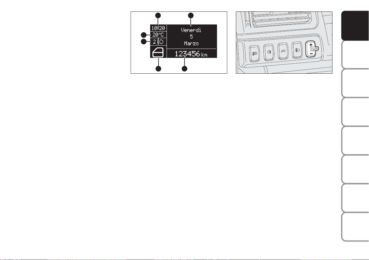
“STANDARD” SCREEN fig. 25
The standard screen shows the following
indications:
A Time
B Date
C Odometer (displays the kilometres, or
miles, covered)
D Vehicle status signals (ex. doors open
or the presence of ice on the road,
etc.)
E Headlamp stability position (only with
low beams on)
F External temperature
Note When opening one of the front
doors, the display will turn on and show
for a few seconds the clock and the km or
mi covered.
fig. 25
F0L0518m
CONTROL BUTTONS fig. 26
+ To scroll the displayed menu and the
related options upwards or to increase
the value displayed.
MODE Brief press to open the menu
and/or to move to next screen or to confirm the option required.
Long press to go back to the standard
screen.
– To scroll the displayed menu and the
related options downwards or to decrease the value displayed.
fig. 26
F0L0029m
Note Buttons + and – activate different
functions according to the following situations:
– to adjust instrument panel, sound sys-
tem and automatic climate control system display brightness when standard
screen is active;
– to scroll the menu options upwards and
downwards;
– to increase or decrease values during set-
tings.
SAFETY
DEVICES
OF THE CAR
CORRECT USE
WARNING
MESSAGES
LIGHTS AND
IN AN
EMERGENCY
CAR
MAINTENANCE
TECHNICAL
SPECIFICATIONS
INDEX
25

DASHBOARD
AND CONTROLS
SAFETY
DEVICES
OF THE CAR
CORRECT USE
WARNING
MESSAGES
LIGHTS AND
IN AN
EMERGENCY
CAR
MAINTENANCE
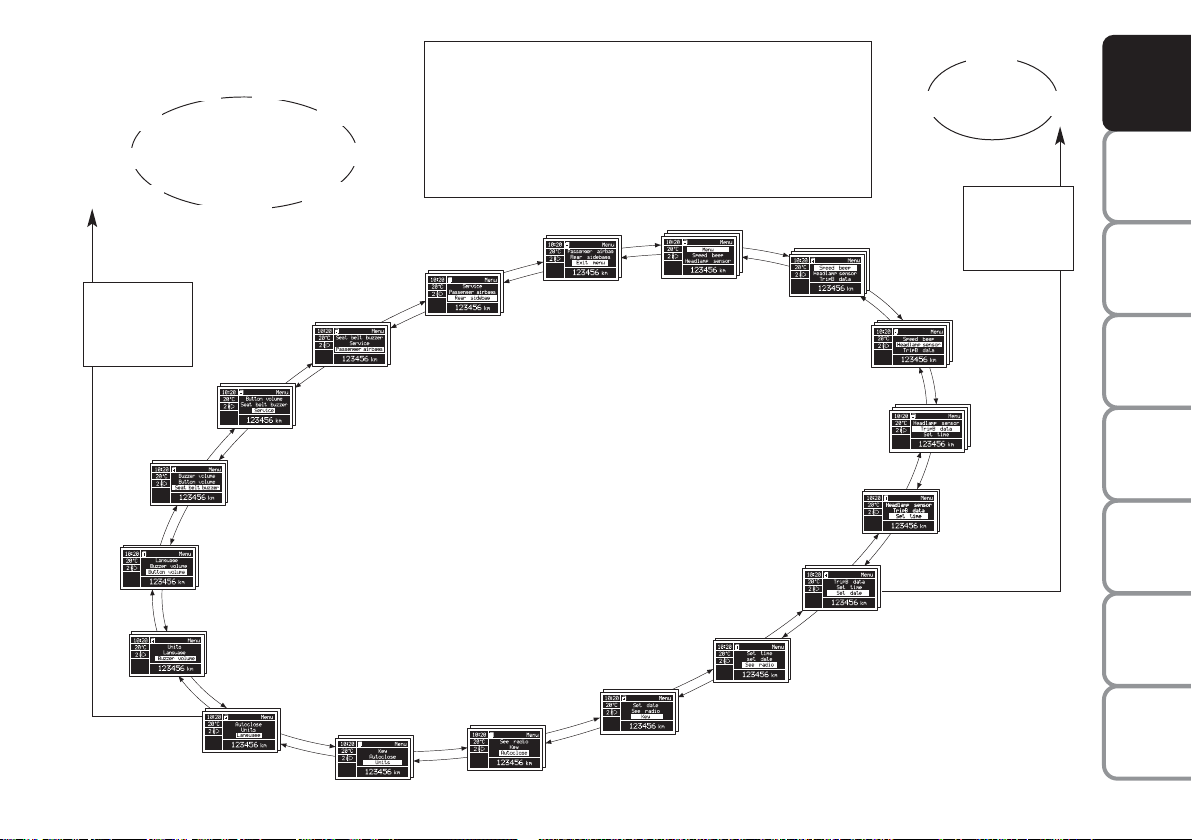
SETUP MENU fig. 27
The menu comprises a series of functions
arranged in a “circular fashion” which can
be selected through buttons + and – to
access the different select operations and
settings (setup) given below. For certain
options (Set time and Units) there is a submenu.
The setup menu can be activated by pressing briefly button MODE.
Single presses on buttons + or – will scroll
the setup menu options. Handling modes
differ with each other according to the
characteristic of the option selected.
If the car is equipped with Connect Nav+,
the only functions that can be adjusted/set
through the instrument panel display are
the following: “Dimmer”, “Speed Beep”,
“Headl. sensor” (where provided), “Belt
buzzer” and “Passenger bag”. The other
functions are displayed by and can be adjusted/set through the Connect Nav+ system display.
Selecting an option in the main menu
without submenu:
– press briefly button MODE to select
the menu option to set;
– press buttons + or – (by single presses) to select the new setting;
– press briefly button MODE to store the
new setting and to go back to the previously selected menu option.
Selecting an option in the main menu with
submenu:
– press briefly button MODE to display
the first submenu option;
– press buttons + or – (by single presses) to scroll all submenu options;
– press briefly button MODE to select
the displayed submenu option and to enter the relevant setup menu;
– press buttons + or – (by single presses) to select the new setting;
– press briefly button MODE to store the
new setting and to go back to the previously selected submenu option.
TECHNICAL
SPECIFICATIONS
INDEX
26
Example:
Italiano
Brasilian
Turkçe
Deutsch
Nederlands
English
Español
Français
Portugês
Briefly press button MODE to start surfing from the standard
screen. To surf the menu use buttons + or -. Note For safety reasons, when the car is running, it is possible to access only the reduced menu (for setting “Dimmer” and “Speed Beep”).
When the car is stationary access to the whole menu is enabled.
On cars provided with Connect Nav+ many functions are displayed on the navigator display.
Year
Day
Month
MODE
briefly press
button
DASHBOARD
AND CONTROLS
SAFETY
DEVICES
MODE
briefly press
button
SERVICE
SEAT BELT BUZZER
BUTTON VOLUME
BUZZER VOLUME
LANGUAGE
REAR SIDEBAGS
PASSENGER AIRBAG
UNITS
AUTOCLOSE
EXIT MENU
KEY
MENU
HEADLAMP SENSOR
SEE RADIO
SPEED BEEP
TRIP B DATA
SET TIME
SET DATE
FF0L4023g
fig. 27
OF THE CAR
CORRECT USE
WARNING
LIGHTS AND
IN AN
EMERGENCY
CAR
MAINTENANCE
TECHNICAL
SPECIFICATIONS
INDEX
27
MESSAGES

DASHBOARD
AND CONTROLS
SAFETY
DEVICES
OF THE CAR
CORRECT USE
WARNING
MESSAGES
LIGHTS AND
IN AN
EMERGENCY
CAR
MAINTENANCE
DISPLAY FUNCTIONS
(see Multifunctional display or Reconfigurable multifunctional display)
Speed Beep (Speed limit)
With this function it is possible to set the
car speed limit (km/h or mph); when this
limit is exceeded the driver is immediately alerted (see section “Warning lights and
messages”).
To set the speed limit, proceed as follows:
– briefly press button MODE, the display
will show wording (Speed Beep);
– press button + or – to select activation
(On) or deactivation (Off) of the speed
limit;
– if selecting (On), press button + or –
to select the required speed limit and then
press MODE to confirm.
Note The possible setting is between 30
and 250 km/h, or between 20 and 155
mph depending on the unit set previously (see “Distance unit (Dist. Unit)” paragraph described later. Every press on button +/– increases/decreases by 5 units.
Keeping the button +/– pressed obtains
the automatic fast increase or decrease.
When you are near the required setting
complete adjustment by single presses.
– briefly press button MODE to go back
to the menu screen or press the button
for long to go back to the standard screen
without storing settings.
To cancel the setting, proceed as follows:
– briefly press button MODE: (On) will
flash on the display;
– press button – : (Off) will flash on the
display;
– briefly press button MODE to go back
to the menu screen or press the button
for long to go back to the standard screen
without storing settings.
TECHNICAL
SPECIFICATIONS
INDEX
28

Headlamp sensor
(Automatic headlight sensor
sensitivity adjustment)
(where provided)
With this function it is possible to adjust
the light sensor sensitivity according to 3
levels (level 1 = min. level, level 2 = average level, level 3 = max. level); the higher the sensitivity is, the lower is the external light intensity required to switch on
the lights.
To set the light level required, proceed as
follows:
– briefly press button MODE, the previously set level will flash on the display;
– press button + or – to select the required level;
– briefly press button MODE to go back
to the menu screen or press the button
for long to go back to the standard screen
without storing settings.
Trip B data (Trip On/Off)
Through this option it is possible to activate (On) or deactivate (Off) the Trip B
(partial trip).
For further information see “Trip computer”.
For activation / deactivation, proceed as
follows:
– briefly press button MODE: On or Off
will flash on the display according to previous setting;
– press button + or – to select the required level;
– briefly press button MODE to go back
to the menu screen or press the button
for long to go back to the standard screen
without storing settings.
Set time (Setting the clock)
This function enables to set the clock
through two sub-menus: “Time” and
“Mode”.
Proceed as follows:
– briefly press button MODE, the display
will show the two submenus “Time” and
“Mode”;
– press button + or – to scroll the two
submenus;
– select the required submenu and then
press briefly MODE;
– if selecting “Time”: briefly press button
MODE, “hours” will flash on the display;
– press button + or – for setting;
– press button MODE, “minutes” will
flash on the display;
– press button + or – for setting.
DASHBOARD
AND CONTROLS
SAFETY
DEVICES
OF THE CAR
CORRECT USE
WARNING
MESSAGES
LIGHTS AND
IN AN
EMERGENCY
CAR
MAINTENANCE
TECHNICAL
INDEX
29
SPECIFICATIONS
 Loading...