


Dear Customer,
Thank you for selecting Fiat and congratulations on your choice of a Fiat SCUDO.
We have written this handbook to help you get to know all your new Fiat SCUDO features and use it in the best possible way.
You should read it right through before taking the road for the first time. You will find information, tips and important warnings regarding the driving of your vehicle to help you derive the maximum from your Fiat SCUDO technological features.
You are recommended to read carefully the warnings and indications, marked with the respective symbols, at the end of the page:
 personal safety;
 the vehicle wellbeing;
 environmental protection.
The enclosed Warranty Booklet lists the services that Fiat offers to its Customers:
the Warranty Certificate with terms and conditions for maintaining its validity
the range of additional services available to Fiat Customers.
Best regards and good motoring!
This Owner Handbook describes all Fiat SCUDO versions.
As a consequence, you should consider only the information which is related to the engine and bodywork version of the vehicle you purchased.

MUST BE READ!
REFUELLING
Only refuel with diesel fuel for motor vehicles conforming to the European specification EN590.
KUsing other products or mixtures may damage the engine beyond repair and cause the forfeiture of the warranty cover for caused damages as a consequence.
STARTING THE ENGINE
Make sure that the handbrake is engaged; set the gearshift lever to neutral; fully depress the clutch pedal, without pressing the accelerator, then turn the ignition key to M and wait for the warning lights Yand m to go off; turn the ignition key to D and release it as soon as the engine has started.
PARKING OVER INFLAMMABLE MATERIAL
While working, the catalyst develops a very high temperature. Do not park the vehicle over grass, dry leaves, pine nee-
dles or any other inflammable materials: risk of fire.
RESPECTING THE ENVIRONMENT
The vehicle is fitted with a system that allows continuous diagnosis of the components correlated with emissions to ensure better respect for the environment.

ELECTRICAL ACCESSORIES
If, after buying the vehicle, you decide to add electrical accessories (that will gradually drain the battery), visit a |
|
Fiat Dealership. They can calculate the overall electrical requirement and check that the vehicle’s electric system can sup- |
|
port the required load. |
|
CODE card
Keep the code card in a safe place, not in the vehicle. You should always keep the electronic code written on the CODE card with you.
SCHEDULED SERVICING
Correct maintenance of the vehicle is essential for ensuring it stays in tip-top condition and safeguards its safety features, its environmental friendliness and low running costs for a long time to come.
THE OWNER HANDBOOK CONTAINS…
… information, tips and important warnings regarding the safe, correct driving of your vehicle, and its maintenance. Pay particular attention to the symbols " (personal safety) # (environmental protection) ! (vehicle wellbeing).

DASHBOARD |
AND CONTROLS |
SAFETY |
DEVICES |
CORRECT USE OF THE VEHICLE |
|
WARNING LIGHTS AND |
MESSAGES |
IN AN |
EMERGENCY |
VEHICLE |
MAINTENANCE |
TECHNICAL |
SPECIFICATIONS |
|
INDEX |
DASHBOARD AND CONTROLS
DASHBOARD ...................................................................... |
5 |
SYMBOLS ............................................................................... |
6 |
THE FIAT CODE SYSTEM ................................................. |
6 |
THE KEYS .............................................................................. |
7 |
ALARM ................................................................................... |
10 |
IGNITION DEVICE ............................................................. |
12 |
INSTRUMENT PANEL ........................................................ |
13 |
INSTRUMENTS .................................................................... |
14 |
DISPLAY.................................................................................. |
15 |
MAINTENANCE INDICATOR ........................................ |
16 |
TRIP COMPUTER................................................................. |
17 |
FRONT SEATS ..................................................................... |
17 |
REAR SEATS .......................................................................... |
20 |
SEAT ARRANGEMENTS .................................................... |
22 |
HEAD RESTRAINTS ........................................................... |
23 |
STEERING WHEEL .............................................................. |
24 |
REARVIEW MIRRORS ........................................................ |
25 |
HEATING AND VENTILATION ..................................... |
27 |
MANUAL CLIMATE CONTROL SYSTEM .................... |
31 |
AUTOMATIC TWO-ZONE CLIMATE |
|
CONTROL SYSTEM ........................................................... |
37 |
AUTOMATIC THREE-ZONE CLIMATE |
|
CONTROL SYSTEM ........................................................... |
45 |
EXTERNAL LIGHTS ............................................................ |
47 |
WINDOW WASHING ...................................................... |
50 |
CRUISE CONTROL SPEED REGULATOR.................... |
54 |
“LIMIT” SPEED RESTRICTOR .......................................... |
57 |
CEILING LIGHTS ................................................................. |
60 |
CONTROLS .......................................................................... |
61 |
FUEL CUT-OFF SWITCH .................................................. |
64 |
INTERIOR EQUIPMENT..................................................... |
65 |
DOORS .................................................................................. |
69 |
SLIDING LUGGAGE COVER............................................ |
73 |
POWER WINDOWS/WINDOW WINDERS .............. |
74 |
BONNET ............................................................................... |
76 |
ROOF RACK/SKI RACK .................................................... |
77 |
PNEUMATIC SUSPENSIONS............................................. |
78 |
LOAD RECOMMENDATIONS......................................... |
79 |
HEADLIGHTS ....................................................................... |
81 |
ABS SYSTEM ......................................................................... |
82 |
ESP SYSTEM .......................................................................... |
84 |
EOBD SYSTEM ..................................................................... |
87 |
PARKING SENSORS ........................................................... |
88 |
SOUND SYSTEM ................................................................. |
89 |
ACCESSORIES PURCHASED BY THE OWNER ......... |
90 |
AT THE FILLING STATION ............................................. |
91 |
PROTECTING THE ENVIRONMENT ........................... |
92 |
4
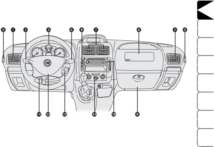
DASHBOARD
The presence and the position of controls, instruments, gauges and warning lights may vary according to the vehicle version.
F0P0600m
fig. 1
1. Side swivel air vents - 2. Side fixed air vents - 3. Left steering column stalk: external lights - 4. Instrument panel - 5. Right steering column stalk: windscreen, rear window and trip computer controls - 6. Dashboard controls - 7. Center swivel air vents - 8. Front passenger air bag (where provided) - 9. Glovebox - 10. Sound system (where provided) - 11. Heating/ventilation/climate controls - 12. Sound system command lever (where provided) - 13. Front driver’s air bag - 14. Steering wheel adjustment lever
DASHBOARD AND CONTROLS |
|
SAFETY |
DEVICES |
CORRECT USE |
OF THE VEHICLE |
WARNING |
LIGHTS AND MESSAGES |
IN AN |
EMERGENCY |
VEHICLE |
MAINTENANCE |
TECHNICAL |
SPECIFICATIONS |
INDEX |
|
5
DASHBOARD |
AND CONTROLS |
SAFETY |
DEVICES |
CORRECT USE OF THE VEHICLE |
|
WARNING LIGHTS AND |
MESSAGES |
IN AN |
EMERGENCY |
VEHICLE |
MAINTENANCE |
TECHNICAL |
SPECIFICATIONS |
|
INDEX |
SYMBOLS
Special coloured labels have been attached near or actually on some of the components of your Fiat SCUDO. These labels bear symbols that remind you of the precautions to be taken as regards that particular component.
THE FIAT CODE SYSTEM
To further protect your vehicle from theft, it has been fitted with an engine immobilising system. This system is automatically activated when the ignition key is removed.
An electronic device, in fact, is fitted in each ignition key grip. The device transmits a radio-frequency signal when the engine is started through a special aerial built into the ignition switch. The modulate signal, which changes each time the engine is started, is the “password”, by means of which the control unit recognises the key and enables to start the engine.
OPERATION
Each time the vehicle is started turning the ignition key to M, the Fiat CODE system control unit sends a recognition code to the engine control unit to deactivate the inhibitor.
The code is sent only if the Fiat CODE system control unit has recognised the code transmitted from the key.
Each time the ignition key is turned to S, the Fiat CODE system deactivates the functions of the engine electronic control unit.
In this case, the key should be moved to S and then back to M; if the lock continues, possibly try again with the other key provided with the vehicle. If it is still not possible to start the vehicle, contact Fiat Dealership.
IMPORTANT Every key has its own code, which must be memorised by the system control unit. To memorise new keys, up to a maximum of eight, apply to Fiat Dealership.
The electronic components inside the key may be damaged if the key is submitted to sharp knocks.
6
THE KEYS
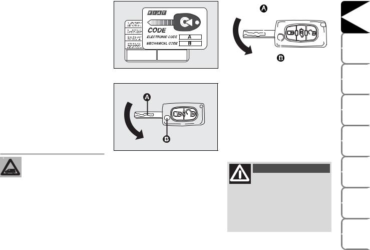
CODE CARD fig. 2
The vehicle is delivered with two copies of the ignition key and with the CODE card which bears the following:
A the electronic code;
Bthe mechanical key code to be given to the Fiat Dealership when ordering duplicate keys.
Make sure you have the electronic code A-fig. 2 with you at all times.
IMPORTANT In order to ensure perfect efficiency of the electronic devices contained inside the keys, they should never be exposed to direct sunlight.
fig. 2 |
F0P0003m |
|
|
|
|
|
|
|
|
|
|
|
|
|
|
|
|
fig. 3a |
|
F0P0321m |
|
|
To refit it proceed as follows:
keep button B pressed and move the metal insert A;
release button B and turn the metal insert A until hearing the proper locking click.
All the keys and the CODE card must be handed over to the new owner when selling the vehicle.
fig. 3 |
F0P0004m |
|
KEY WITH REMOTE CONTROL fig. 3/a
The metal insert A is retractable and it operates:
ignition switch;
door locks;
fuel filler cap locking/unlocking.
To extract the metal insert, press button
B.
WARNING
Button B should only be pressed when the key is away from the body, in particular
from the eyes and from objects that can be spoilt (e.g. clothes). Make sure the key can never be touched by others, especially children, who may inadvertently press the button.
DASHBOARD AND CONTROLS |
|
SAFETY |
DEVICES |
CORRECT USE |
OF THE VEHICLE |
WARNING |
LIGHTS AND MESSAGES |
IN AN |
EMERGENCY |
VEHICLE |
MAINTENANCE |
TECHNICAL |
SPECIFICATIONS |
INDEX |
|
7

DASHBOARD |
AND CONTROLS |
SAFETY |
DEVICES |
CORRECT USE OF THE VEHICLE |
|
WARNING LIGHTS AND |
MESSAGES |
IN AN |
EMERGENCY |
VEHICLE |
MAINTENANCE |
TECHNICAL |
SPECIFICATIONS |
|
INDEX |
|
8 |
Passenger compartment Unlocking
ª By first pressing on this button, it allows you to unlock the vehicle passenger compartment doors.
The direction indicator lamps flash twice. By pressing a second time, it allows the unlocking of one or more side doors as well as the rear doors.
This selective opening function is activated upon the delivery of the vehicle. Upon request, it is possible to deactivate the selective opening procedure between the passenger compartment and the loading compartment. Please seek advice from the Fiat Dealership.
Unlocking of loading compartment
` By pressing this button all rear doors are unlocked.
This separation of the locks between passenger compartment and loading compartment is a safety device which allows the closure of the vehicle accesses of the area from which one is absent.
Centralised locking
∫ By pressing on this command, it allows the locking of the passenger compartment and rear doors. The direction indicator lamps flash once.
If one of the front doors is open or not properly closed, central locking cannot take place.
Dead Lock (where required)
Where provided, pressing twice the remote control button ∫ five seconds after locking the doors will activate the dead lock (super-locking of the doors).
Dead lock activation is indicated by direction indicators coming on with fixed light for about two seconds.
The dead lock disables the internal and external handles of the doors.
WARNING
Never leave passengers inside the vehicle when the
dead lock is active.
IMPORTANT If the dead lock is activated from the inside of the vehicle, this will turn to a simple locking upon starting the engine.
fig. 4 |
F0P0006m |
|
Dashboard led indications
When locking the doors, led A-fig. 4 will start flashing (deterrence function).
Once doors are locked if one or more doors are not closed correctly, the instrument panel warning light 9will turn on.

Request for additional remote controls
The system can recognise up to 8 remote controls. Should a new remote control be necessary, contact a Fiat Dealership taking with you the CODE card, a personal identity document and the vehicle’s ownership documents.
Replacing the battery of the key with remote control
Battery replacement:
separate the two casings A and B-fig. 6, by levering in the point shown by the arrow in fig. 5;
take out the battery and replace it C- fig. 6;
refit both casings, make sure they lock into place;
|
|
fig. 5 |
F0P0007m |
|
|
|
|
|
Used batteries are harmful to |
|
|
|
the environment. They should |
|
be disposed of as specified by |
|
law in the special containers |
provided, or take them to a Fiat Dealership, which will deal with their disposal.
|
|
|
|
|
|
|
|
|
|
|
|
|
|
|
|
|
|
|
|
fig. 6 |
F0P0008m |
|||
|
||||
Re-initialisation of the remote control set
After the substitution of batteries or the disconnection of the battery (vehicle), it is necessary to re-initialise the remote control set:
Wait at least a minute before using the remote control set and put it in position A.
Insert the key with the remote control set into the starting switch.
Within ten seconds, press one of the
two buttons (∫ or ª) for at least 5 seconds.
Take the key with the remote control set from the starting switch.
Wait at least a minute before using the remote control. The remote control set works once more.
DASHBOARD AND CONTROLS |
|
SAFETY |
DEVICES |
CORRECT USE |
OF THE VEHICLE |
WARNING |
LIGHTS AND MESSAGES |
IN AN |
EMERGENCY |
VEHICLE |
MAINTENANCE |
TECHNICAL |
SPECIFICATIONS |
INDEX |
|
9
DASHBOARD |
AND CONTROLS |
SAFETY |
DEVICES |
CORRECT USE OF THE VEHICLE |
|
WARNING LIGHTS AND |
MESSAGES |
IN AN |
EMERGENCY |
VEHICLE |
MAINTENANCE |
TECHNICAL |
SPECIFICATIONS |
|
INDEX |
|
|
fig. 7 |
F0P0601m |
|
KEY WITHOUT REMOTE CONTROL fig. 7
The metal insert of the key A is fixed.
The key operates:
ignition switch;
door locks;
fuel filler cap locking/unlocking.
ALARM
(where provided)
If the vehicle is equipped with alarm, the following two types of protection can be activated:
perimetrical (alarm active in case of a front/back door or the engine bonnet opening);
volumetric protection (alarm on if the volume inside the passenger compartment changes).
Activation (complete volumetric and perimetrical alarm)
Take the key from the switch
Get out of the vehicle
Press the button ∫ (dead lock - once or twice)
The deterrence led starts to flash.
Activation
(only perimetrical alarm)
Take the key from the switch
Within 10 seconds press the button fig. 7a keeping it pressed down until the deterrence led remains switched on.
Get out of the vehicle.
Press the button ∫ (dead lock - once or twice).
The deterrence led starts to flash.
fig. 7a |
F0P0062m |
|
Alarm deactivation
In order to deactivate the alarm, press the ªbutton, the deterrence led will switch off.
10

The main functions that can be activated with the keys (with or without remote control) are the following:
Type of key |
|
Door |
|
Door closing |
|
Dead lock |
|
Tailgate |
|
Window |
|
Window |
|
|
opening |
|
form the |
|
activation |
|
opening |
|
opening |
|
closing |
|
|
|
|
outside |
|
(where |
|
(where |
|
(where |
|
(where |
|
|
|
|
|
|
provided) |
|
provided) |
|
provided) |
|
provided) |
Key without remote control |
|
Key turning |
|
Key turning |
|
|
|
|
|
|
|
|
|
|
counterclockwise |
|
clockwise |
|
|
|
|
|
|
|
|
|
|
(driver side and |
|
(driver side and |
|
– |
|
– |
|
– |
|
– |
|
|
side sliding door, |
|
side sliding door, |
|
|
|
|
|
|
|
|
|
|
where provided) |
|
where provided) |
|
|
|
|
|
|
|
|
|
|
Key turning |
|
Key turning |
|
|
|
|
|
|
|
|
|
|
counterclockwise |
|
clockwise |
|
|
|
|
|
|
|
|
|
|
(driver side and |
|
(driver side and |
|
– |
|
– |
|
– |
|
– |
|
|
side sliding door, |
|
side sliding door, |
|
|
|
|
|
|
|
|
Key with remote control |
|
where provided) |
|
where provided) |
|
|
|
|
|
|
|
|
|
|
Press briefly |
|
Press briefly |
|
Double pressing |
|
|
|
Long press |
|
Long press |
|
|
button ª |
|
button ∫ |
|
on button ∫ |
|
– |
|
(over 2 |
|
(over 2 |
|
|
|
|
|
|
|
|
|
seconds) |
|
seconds) |
|
|
|
|
|
|
|
|
|
|
|
on button ª |
|
on button ∫ |
Direction indicators |
|
2 flashings |
|
1 flashing |
|
3 flashings |
|
2 flashings |
|
2 flashings |
|
1 flashing |
flashing (only with key with |
|
|
|
|
|
|
|
|
|
|
|
|
remote control) |
|
|
|
|
|
|
|
|
|
|
|
|
|
|
|
|
|
|
|
|
|
|
|
|
|
IMPORTANT Window opening operation is a consequence of a door unlocking control; window closing operation is a consequence of a door locking control.
DASHBOARD AND CONTROLS |
|
SAFETY |
DEVICES |
CORRECT USE |
OF THE VEHICLE |
WARNING |
LIGHTS AND MESSAGES |
IN AN |
EMERGENCY |
VEHICLE |
MAINTENANCE |
TECHNICAL |
SPECIFICATIONS |
INDEX |
|
11

DASHBOARD |
AND CONTROLS |
SAFETY |
DEVICES |
CORRECT USE OF THE VEHICLE |
|
WARNING LIGHTS AND |
MESSAGES |
IN AN |
EMERGENCY |
VEHICLE |
MAINTENANCE |
TECHNICAL |
SPECIFICATIONS |
|
INDEX |
IGNITION
DEVICE
The key can be turned to 4 different positions fig. 8:
S: engine off, key can be removed, steering column locked.
A: certain electrical devices can work.
M: driving position. All electrical devices are powered.
D: engine starting (unstable position).
WARNING
If the ignition device is tampered with (e.g.: attempted theft), have it checked over by a Fiat
Dealership as soon as possible.
fig. 8 |
F0P0010m |
|
WARNING
When getting out of the vehicle, always remove the key to prevent any occupants from acci-
dentally activating the controls. Remember to engage the handbrake and if the vehicle is parked on uphill slope to engage the first gear. If the vehicle is facing downhill, engage the reverse gear. Never leave unsupervised children in the vehicle.
STEERING COLUMN LOCK
Engaging
When the key is at S, remove the key and turn the steering wheel until it locks.
Disengaging
Rock the steering wheel slightly as you turn the ignition key to M.
WARNING
Never remove the ignition key while the vehicle is moving. The steering wheel would auto-
matically lock as soon as you try to turn it. This also applies when the vehicle is being towed.
WARNING
It is absolutely forbidden to carry out whatever aftermarket operation involving steering system or steering column modifications (e.g.: installation of anti-theft device) that could badly affect performance and safety, cause the lapse of warranty and also result in noncompliance of the vehicle with ho-
mologation requirements.
12

INSTRUMENT PANEL
fig. 9 |
F0P0012m |
A Speedometer (speed indicator)
BFuel level gauge with reserve warning light
CEngine coolant temperature gauge and excessive temperature warning light
D Rev counter
E Multifunction display
DASHBOARD AND CONTROLS |
|
SAFETY |
DEVICES |
CORRECT USE |
OF THE VEHICLE |
WARNING |
LIGHTS AND MESSAGES |
IN AN |
EMERGENCY |
VEHICLE |
MAINTENANCE |
TECHNICAL |
SPECIFICATIONS |
INDEX |
|
13

DASHBOARD |
AND CONTROLS |
SAFETY |
DEVICES |
CORRECT USE OF THE VEHICLE |
|
WARNING LIGHTS AND |
MESSAGES |
IN AN |
EMERGENCY |
VEHICLE |
MAINTENANCE |
TECHNICAL |
SPECIFICATIONS |
|
INDEX |
INSTRUMENTS
Instrument background color and type may vary according to the version.
SPEEDOMETER fig. 10
It shows the engine speed.
REV. COUNTER fig. 11/a
Rev counter shows engine rpm.
IMPORTANTTheelectronicinjectioncontrol system gradually shuts off the flow of fuel when the engine is “over-revving” resulting in a gradual loss of engine power.
When the engine is idling, the rev counter may indicate a gradual or sudden highering of the speed.
This is normal and takes place for example when activating the climate control system or the fan. In these events a slight increase in engine idling preserves the battery charge.
FUEL LEVEL GAUGE B-fig. 11/b
This shows the amount of fuel left in the fuel tank.
fig. 10 |
F0P0013m |
|
|
|
fig. 11/a |
F0P0014m |
|
K tank full (See the indications given in paragraph “At the filling station”).
å tank empty.
The reserve warning light K turns on to indicate that approximately 7 litres of fuel are left in the tank.
Do not travel with the fuel tank almost empty: the gaps in fuel delivery could damage the catalyst.
fig. 11/b |
F0P0320m |
|
ENGINE COOLANT TEMPERATURE GAUGE C-fig. 11/b
This shows the temperature of the engine coolant fluid and begins working when the fluid temperature exceeds approx. 50°C.
Under normal conditions, the needle should hover around the middle of the scale according to the working conditions.
å Low engine coolant temperature. u High engine coolant temperature.
If the needle reaches the red area, stop the engine immediately and contact a Fiat Dealership.
14
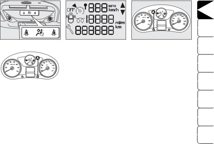
fig. 12 |
F0P0285m |
|
fig. 14 |
F0P0291m |
fig. 15 |
F0P0292m |
|
|
fig. 13 |
F0P0353m |
|
Warning lights on the upper plate
On certain versions, the upper plate fig. 12 (located above the driving mirror) can be fitted with the following warning lights:
warning light indicating that the seat belt is not fastened (<) (version with two front seats).
warning light indicating that the passenger air bag is off (“)
INSTRUMENT PANEL
BRIGHTNESS ADJUSTER
To adjust the instrument panel brightness: press button A-fig. 13
DISPLAY
The display fig. 14 shows by the relevant warning lights (see section “Warning lights and messages”):
speed limiter / control;
total km / mi covered;
engine oil level gauge;
water in diesel fuel filter;
glow plug preheating.
According to versions the display shows the time.
Setting the clock through the instrument panel display
Tosettheclockthroughtheinstrumentpanel display, use button A-fig. 15 as follows:
turning the button leftwards makes the minute value flash;
turning the button rightwards will increase minute value (keep the button turned rightwards to speed up rolling);
turning the button leftwards makes the hour value flash;
turning the button rightwards will increase hour value (keep the button turned rightwards to speed up rolling);
turning the button leftwards selects 24H or 12H mode display;
turn the button rightwards to select the required mode;
turn the button leftwards to stop clock setting.
If no other setting is made, after about 30 seconds the display will show the time according to the selected settings.
Setting the clock through the display on the central console
Certain versions are fitted with a central console with a display showing the time. To set the clock consult the trip computer under option “Set clock and date”.
DASHBOARD AND CONTROLS |
|
SAFETY |
DEVICES |
CORRECT USE |
OF THE VEHICLE |
WARNING |
LIGHTS AND MESSAGES |
IN AN |
EMERGENCY |
VEHICLE |
MAINTENANCE |
TECHNICAL |
SPECIFICATIONS |
INDEX |
|
15 |
|
DASHBOARD |
AND CONTROLS |
SAFETY |
DEVICES |
CORRECT USE OF THE VEHICLE |
|
WARNING LIGHTS AND |
MESSAGES |
IN AN |
EMERGENCY |
VEHICLE |
MAINTENANCE |
TECHNICAL |
SPECIFICATIONS |
|
INDEX |
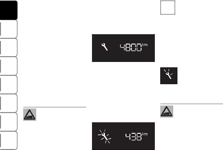
MAINTENANCE
INDICATOR
Itregulatestheintervalsbetweenthemaintenance operations based on vehicle use.
Functioning
As soon as the starting key is inserted and forafewseconds,themaintenancekeylights upandwhichindicatesthemaintenanceoperations;thetotalodometerdisplayindicates the number of kilometres {rounded down} which can be covered until the next maintenanceoperation.Themaintenanceexpiry datesarecalculatedstartingfromthelastresetting of the indicator.
This expiry date is determined by means of two parameters:
the distance in kilometres covered
time which has passed since the last maintenance operation.
The distance in kilometres which remains to be covered can be considered by the time factor, based on the driver’s
driving habits.
Maintenance expiry date over 1,000 km
Example: one can still travel 4,800 km before the next maintenance operation. After having turned the starting key to the M position and for a few seconds, the display indicates:
F0P0354m
A few seconds after having turned the starting key to the M position, the oil level is shown, therefore the total odometer works again and it indicates the total and daily amount of kilometres travelled.
Maintenance expiry date less than 1,000 km
After having turned the starting key to the M position and for a few seconds, the maintenance key flashes and the remaining number of kilometres is shown.
F0P0355m
ENGINE OIL LEVEL OIL OK INDICATOR
Turning the starting key to the M position, the instrument, after having shown the kilometres to be covered before the next maintenance operation, supplies the synchronised indication of the oil level present in the engine oil pan. The flashing of the word “OIL”, accompanied by a beeping and by a message, indicates an insufficient quantity of oil in the engine. The flashing of the word “OIL –“ indicates a problem with the engine oil sensor.
Maintenance Expiry date exceeded
After having turned the  starting key to the M posi-
 tion and for a few seconds,
 the maintenance key flashes F0P0356m and the number of kilome-
tres
travelled after the expiry date of the maintenance operation is shown.
Whentheengineisrunning,the maintenance key remains switch until the maintenance operationhasbeencarriedout.
Before the two expiry dates are reached: the maintenance key lights up also when the expiry date of two years has been exceeded.
16

TRIP COMPUTER
The trip computer enables to display in sequence, by pressing repeatedly button fig. 16 set on the top of the steering column stalk, the following values:
range, instant consumption, distance to cover, trip 1 (trip distance, average consumption, average speed) and trip 2 (trip distance, average consumption, average speed).
This information is displayed on the display of the infotelematic CONNECT system.
Reset: press button shown in fig. 16 for over 2 seconds for resetting.
Range
This value shows the distance in km (or mi) that the vehicle can still cover before needing fuel, assuming that driving conditions are kept unvaried.
Instant consumption
This value shows average fuel consumption calculated during the last seconds of travel.
fig. 16 |
F0P0041m |
|
Distance to cover
This value shows the distance to be covered yet, under active navigation condition.
Trip distance
This value shows the distance covered from the start of the journey, after resetting (Reset).
Average consumption
This value shows the average consumption from the start of the journey, after resetting (Reset).
Average speed
This value shows the vehicle average speed calculated from the start of the journey, after resetting (Reset).
FRONT SEATS
WARNING
Onlymakeadjustmentswhen the vehicle is stationary.
Fabric upholstery of your Fiat SCUDO is purpose-made to withstand common wear resulting from normal use of the
vehicle. It is however absolutely necessary to prevent hard and/or prolonged scratching/scraping caused by clothing accessories like metallic buckles, studs, “Velcro” fixings, etc. that stressing locally the fabric could break yarns and damage the upholstery as a consequence.
DASHBOARD AND CONTROLS |
|
SAFETY |
DEVICES |
CORRECT USE |
OF THE VEHICLE |
WARNING |
LIGHTS AND MESSAGES |
IN AN |
EMERGENCY |
VEHICLE |
MAINTENANCE |
TECHNICAL |
SPECIFICATIONS |
INDEX |
|
17
DASHBOARD AND |
CONTROLS |
SAFETY |
DEVICES |
CORRECT USE |
OF THE VEHICLE |
WARNING LIGHTS AND |
MESSAGES |
IN AN |
EMERGENCY |
VEHICLE |
MAINTENANCE |
TECHNICAL |
SPECIFICATIONS |
|
INDEX |
|
18 |
fig. 17 |
F0P0015m |
fig. 18 |
F0P0322m |
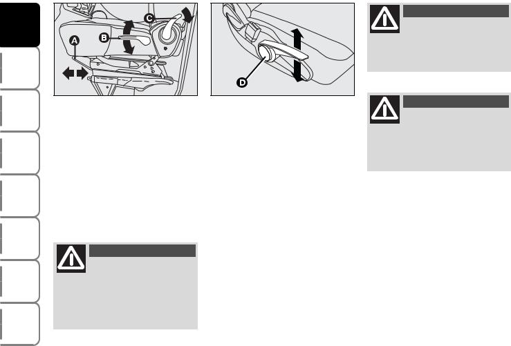
Moving the seat backwards or forwards fig. 17
Lift the lever A and push the seat forwards or backwards: in the driving position the arms should rest on the rim of the steering wheel. Once you have released the lever, check that the seat is firmly locked in the runners by trying to move it back and forth.
WARNING
Once you have released the lever, check that the seat is firmly locked in the runners by trying
to move it back and forth. Failure to lock the seat in place could result in the seat moving suddenly and the driver losing control of the vehicle.
Regulation of the height of the driver’s seat fig. 17-18
Depending on the version and the configuration of the vehicle, it is equipped with:
a passive regulation: pull lever B upwards, therefore get off the seat in order to allow it to rise.
an active regulation: pull lever D upwards or downwards until the desired position is desired.
Back rest angle adjustment fig. 17
Use lever C and adjust the back rest.
WARNING
For maximum safety, keep the back of your seat upright, lean back into it and make sure
the seat belt fits closely across your chest and hips.
WARNING
Do not remove the seats or carry out servicing and/or repair operations since incorrect oper-
ations could impair the regular operation of safety devices: always contact Fiat Dealership.
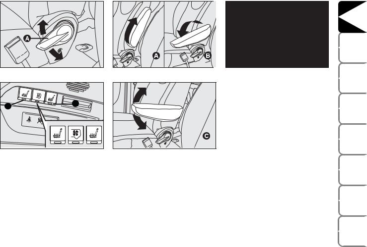
fig. 18/a |
F0P0016m |
fig. 20 |
F0P0018m |
fig. 22 |
F0P0122m |
|
|
|
|
FRONT TWO-SEAT |
|
|
|
|
|
BENCH (where provided) |
|
A |
B |
|
|
It is fix and it is fitted with three point belt |
|
|
|
|
and belt retractor. |
|
|
|
|
|
|
|
|
|
|
|
|
It can be fitted with a folding shelf fig. 22 |
|
|
|
|
|
to be used like supporting surface. Pull the |
|
|
|
|
|
tab to use it. |
|
fig. 19 |
F0P0017m |
fig. 21 |
F0P0019m |
|
|
Lumbar adjustment (where provided) fig. 18/a
Use lever A to adjust the seat as required.
Seat warming
(where provided) fig. 19
With ignition key at M, press button A or B (driver’ssideorpassenger’sside)toswitchthe seatwarmingon/off.Theledonthebuttonwill lightupwhenthefunctionison.
FRONT ARMRESTS (where provided) fig. 20-21
Certain versions are fitted with two armrests between front seats.
To adjust the armrests proceed as follows:
raise the armrest and bring it to position A;
lower the armrest and bring it down to completely to position B;
raisethearmrestagainandbringittothe required position C.
DASHBOARD AND CONTROLS |
|
SAFETY |
DEVICES |
CORRECT USE |
OF THE VEHICLE |
WARNING |
LIGHTS AND MESSAGES |
IN AN |
EMERGENCY |
VEHICLE |
MAINTENANCE |
TECHNICAL |
SPECIFICATIONS |
INDEX |
|
19
DASHBOARD AND |
CONTROLS |
SAFETY |
DEVICES |
CORRECT USE |
OF THE VEHICLE |
WARNING LIGHTS AND |
MESSAGES |
IN AN |
EMERGENCY |
VEHICLE |
MAINTENANCE |
TECHNICAL |
SPECIFICATIONS |
|
INDEX |
REAR SEATS
Single seat
This seat can be folded to facilitate access to the rear area and it can be removed.
Certain versions can be fitted with a shelf obtained in the back of the seat.
To use it, operate the release lever A-fig. 23 and guide the seat back onto the cushion.
To remove and then to refit the seat keep the back rest firmly lowered and flattened against the cushion to pre-
vent any contact between the seat articulation mechanisms.
fig. 23 |
F0P0022m |
|
fig. 24 |
F0P0023m |
|
Folding/removing the single seat
To fold the back of the seat pull handle A- fig. 23 upwards.
To remove the seat proceed as follows:
operate handle A-fig. 24 and guide the seat forward as shown in the figure;
lift the seat to make the pins come out of their anchorings and then remove it taking care to keep the back rest firmly lowered and flattened against the cushion.
TWO-SEAT BENCH
According to versions it can be of different types:
2-seat bench with fix back rest;
removable 2-seat bench with back rests wrapping individually;
removable 2-seat bench with back rests folding individually or wrapping in “table” position.
FOLDING, REMOVING AND REFITTING THE REAR BENCH SEAT
WARNING
To remove and then to refit the bench seat, keep the back rest firmly lowered and
flattened against the cushion to prevent any contact between the seat articulation mechanisms.
20
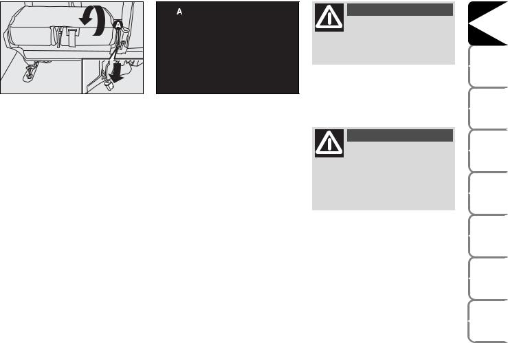
fig. 25 |
F0P0024m |
|
fig. 26 |
F0P0025m |
|
To fold the back rest pull lever A-fig. 25.
To remove the seat proceed as follows:
– lower the head restraints completely;
–fold the back rest as described previously;
–lift lever A-fig. 26 and fold the seat;
–lift the seat to make the pins come out of their anchorings and remove it taking care to keep the back rest firmly lowered and flattened against the cushion.
To refit the seat proceed as follows:
–lift the bench seat and secure the pins to their anchorings on the floor, make sure they lock properly into place;
–guide the bench seat until rear anchorings lock automatically.
WARNING
Make sure the floor anchoring seats are always clean; foreign matters could impair
proper seat anchoring.
WARNING
Before starting to drive make sure all seats are facing the running direction and perfectly anchored. Only this position ensures the effectiveness of
seat belts.
DASHBOARD AND CONTROLS |
|
SAFETY |
DEVICES |
CORRECT USE |
OF THE VEHICLE |
WARNING |
LIGHTS AND MESSAGES |
IN AN |
EMERGENCY |
VEHICLE |
MAINTENANCE |
TECHNICAL |
SPECIFICATIONS |
INDEX |
|
21 |
|

DASHBOARD AND |
CONTROLS |
SAFETY |
DEVICES |
CORRECT USE |
OF THE VEHICLE |
WARNING LIGHTS AND |
MESSAGES |
IN AN |
EMERGENCY |
VEHICLE |
MAINTENANCE |
TECHNICAL |
SPECIFICATIONS |
|
INDEX |
SEAT ARRANGEMENTS
Depending on the various versions it is possible to vary the seat arrangement using the relevant preset housings on the floor.
The following figures show some configurations that can be obtained according to the version requested.
fig. 27 - 4 seats
fig. 28 - 5 seats
fig. 29 - 6 seats
|
|
|
F0P0123m |
fig. 30 - 7 seats |
F0P0126m |
|
|
|
|
|
|
F0P0124m |
fig. 31 - 8 seats |
F0P0127m |
|
|
|
|
|
|
F0P0125m |
fig. 32 - 9 seats |
F0P0128m |
22
IMPORTANT Following a different seat layout:
if you take the head rest off, replace it ad fix it to a support
check that the safety belts are still accessible and easy for the passenger to fasten
a passenger must never travel without having correctly regulated the head rest or without having regulated and fastened the safety belt.
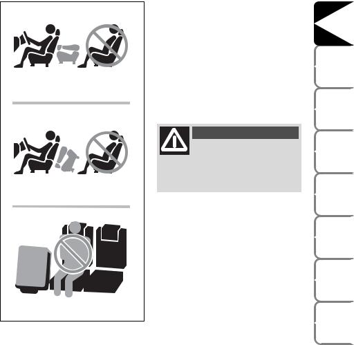
ATTENTION fig. 32/a
Whilst you are driving, it is forbidden to carry a passenger:
in third row if the backboard placed in front (second row) is in the table position;
in third row if the seat/coach placed in front (second row) is in a folded position;
on the centre seat if the right side seat is in a folded position.
fig. 32/a |
F0P0323m |
|
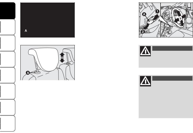
HEAD RESTRAINTS
To raise:
raise the head restraint until hearing the locking click.
To lower:
press buttons A-fig. 33 or A-fig. 34 and lower the head restraint.
WARNING
Remember that the head restraints should be adjusted to support the back of your head and
not your neck. Only in this position do they exert their protective action
DASHBOARD AND CONTROLS |
|
SAFETY |
DEVICES |
CORRECT USE |
OF THE VEHICLE |
WARNING |
LIGHTS AND MESSAGES |
IN AN |
EMERGENCY |
VEHICLE |
MAINTENANCE |
TECHNICAL |
SPECIFICATIONS |
INDEX |
|
23
DASHBOARD AND |
CONTROLS |
SAFETY |
DEVICES |
CORRECT USE |
OF THE VEHICLE |
WARNING LIGHTS AND |
MESSAGES |
IN AN |
EMERGENCY |
VEHICLE |
MAINTENANCE |
TECHNICAL |
SPECIFICATIONS |
|
INDEX |
|
|
STEERING WHEEL |
|
|
|
|
|
The driver can adjust the steering wheel |
|
|
|
|
|
position both axially and in height. |
|
|
|
|
|
To adjust the armrests proceed as follows: |
|
|
|
|
|
release the lever A-fig. 35 pushing it |
|
|
|
|
|
forwards (position 2); |
|
|
|
fig. 33 |
F0P0026m |
adjust the steering wheel as required; |
fig. 35 |
F0P0028m |
|
lock the lever A pulling it towards the |
|||||
|
|
||||
|
|
steering wheel (position 1). |
|
WARNING |
|
|
|
|
|
||
|
|
|
|
Any adjustment of the steer- |
|
|
|
|
|
ing wheel position must be |
|
|
|
|
carried out only with the vehicle sta- |
||
|
|
|
tionary and the engine turned off. |
||
|
|
|
WARNING |
fig. 34 |
F0P0027m |
|
It is absolutely forbidden to |
|
|
||
To optimise head restraint protective ac- |
carry out whatever after- |
||
market operation involving steering |
|||
tion, adjust the seat back upright and keep |
system or steering column modifica- |
||
your head as close as possible to the head |
tions (e.g.: installation of anti-theft |
||
restraint. |
|
|
device) that could badly affect per- |
|
|
|
formance and safety, cause the lapse |
|
|
|
of warranty and also result in non- |
|
|
|
compliance of the vehicle with ho- |
|
|
|
mologation requirements. |
24

REARVIEW MIRRORS
DRIVING MIRROR fig. 36
The mirror is fitted with a safety device that causes it to be released in the event of a violent crash.
It can be adjusted through lever A-fig. 36:
normal position |
fig. 36 |
F0P0029m fig. 38 |
F0P0031m |
|
antiglare position. |
||||
|
|
|
||
|
|
Electrical adjustment fig. 38 |
|
|
|
|
The mirrors can only be adjusted electri- |
||
|
|
cally when the key is at M. |
|
|
|
|
To adjust the armrests proceed as follows: |
||
|
|
use switch A to select the mirror re- |
||
|
|
quired (left or right); |
|
|
|
|
to adjust the mirror move the switch B |
||
|
fig. 37 |
in the four directions; |
|
|
|
F0P0030m |
|
||
|
|
|
||
|
DOOR MIRRORS |
Electrical folding fig. 38 |
|
|
|
It is possible only with the starting key in |
|||
|
|
|||
|
Manual adjustment fig. 37 |
the M position. |
|
|
|
Take switch A to the central position, |
|||
|
Use knob A. |
|||
|
therefore move switch B backwards. |
|||
|
|
|||
DASHBOARD AND CONTROLS |
|
SAFETY |
DEVICES |
CORRECT USE |
OF THE VEHICLE |
WARNING |
LIGHTS AND MESSAGES |
IN AN |
EMERGENCY |
VEHICLE |
MAINTENANCE |
TECHNICAL |
SPECIFICATIONS |
INDEX |
|
25

DASHBOARD AND |
CONTROLS |
SAFETY |
DEVICES |
CORRECT USE |
OF THE VEHICLE |
WARNING LIGHTS AND |
MESSAGES |
IN AN |
EMERGENCY |
VEHICLE |
MAINTENANCE |
TECHNICAL |
SPECIFICATIONS |
|
INDEX |
fig. 39 |
F0P0032m |
|
Folding
When required (for example when the mirror causes difficulty in narrow spaces) it is possible to fold the mirror moving it from position 1-fig. 39 to position 2.
Demisting/defrosting (where provided)
Mirrors are fitted with resistors that will activate when turning the heated rear window on (by pressing button ().
IMPORTANT This function is timed and it will turn off automatically a few minutes later.
WARNING
The lower part of the external rear-view mirror on the driver’s side, with it being curved, it slightly alters the perception of dis-
tance.
When driving the mirrors shall always be in position 1-fig. 39.
26

fig. 40 |
F0P0033m |
|
fig. 41 |
F0P0101m |
|
HEATING AND VENTILATION
1.Fixed upper vent
2.Central swivel vents
3.Fixed side vents
4.Side swivel vents
5.Lower vents for front seats
6.Upper vents for rear seats (where provided).
DASHBOARD AND CONTROLS |
|
SAFETY |
DEVICES |
CORRECT USE |
OF THE VEHICLE |
WARNING |
LIGHTS AND MESSAGES |
IN AN |
EMERGENCY |
VEHICLE |
MAINTENANCE |
TECHNICAL |
SPECIFICATIONS |
INDEX |
|
27 |
|

DASHBOARD AND |
CONTROLS |
SAFETY |
DEVICES |
CORRECT USE |
OF THE VEHICLE |
WARNING LIGHTS AND |
MESSAGES |
IN AN |
EMERGENCY |
VEHICLE |
MAINTENANCE |
TECHNICAL |
SPECIFICATIONS |
|
INDEX |
fig. 42 |
F0P0034m |
|
|
fig. 43 |
F0P0035m |
|
SIDE AND CENTRAL VENTS fig. 42-43
Vents can be directed in the four positions shown by the arrows.
A Fixed vent for side windows. B Side adjustable vents.
C Centre adjustable vents.
Vents A are fixed.
To use vents B and C, operate the relevant device to turn them as required.
fig. 44
CONTROLS fig. 44
Air distribution slider A
μto convey air to the centre and side vents;
∑to warm the feet and convey cooler air to the dashboard vents, in intermediate temperature conditions;
∂to heat with outside harsh temperature: to convey as much air as possible to the feet;
F0P0036m
∏to warm the feet and at the same time demist the windscreen;
-for quick windscreen demisting.
28

Fan activation /speed adjustment knob B
0 = fan off
1-2-3 = fan speed
4 - p = max. fan speed
Air temperature slider C (mixing hot and cold air)
Red section = hot air
Blue section = cold air
Air recirculation on/off button D
Press the button to turn air recirculation on.
Press the button again to turn air recirculation off.
VENTILATION
To ventilate the passenger’s compartment properly proceed as follows:
turn slider C to blue section;
turn air recirculation off (if on);
turn slider A to μ;
slider B turned to the required speed.
WARMING THE PASSENGER COMPARTMENT
Proceed as follows:
turn slider C to red section;
turn slider A to the required position;
slider B turned to the required speed.
FAST HEATING
For fast heating of the passenger compartment, proceed as follows:
turn slider C to red section;
turn air recirculation on (if off);
turn slider A to ∂;
turn slider B to 4 - p (max. fan speed).
Then use the controls to keep the required comfort conditions and press button D to turn air recirculation off and to prevent misting up.
IMPORTANT With cold engine, you have to wait for a few minutes to let the system fluid reach the operating temperature.
DASHBOARD AND CONTROLS |
|
SAFETY |
DEVICES |
CORRECT USE |
OF THE VEHICLE |
WARNING |
LIGHTS AND MESSAGES |
IN AN |
EMERGENCY |
VEHICLE |
MAINTENANCE |
TECHNICAL |
SPECIFICATIONS |
INDEX |
|
29
 Loading...