

Page 1

+
FANUC MANUAL GUIDE
Common to Lathe System/Machining Center System
OPERATOR'S MANUAL
B-63874EN/11
Page 2

• No part of this manual may be reproduced in any form.
• All specifications and designs are subject to change without notice.
The products in this manual are controlled based on Japan’s “Foreign Exchange and
Foreign Trade Law”. The export from Japan may be subject to an export license by the
government of Japan.
Further, re-export to another country may be subject to the license of the government of
the country from where the product is re-exported. Furthermore, the product may also be
controlled by re-export regulations of the United States government.
Should you wish to export or re-export these products, please contact FANUC for advice.
In this manual we have tried as much as possible to describe all the various matters.
However, we cannot describe all the matters which must not be done, or which cannot be
done, because there are so many possibilities.
Therefore, matters which are not especially described as possible in this manual should be
regarded as ”impossible”.
This manual contains the program names or device names of other companies, some of
which are registered trademarks of respective owners. However, these names are not
followed by ® or ™ in the main body.
Page 3
B-63874EN/11 SAFETY PRECAUTIONS
SAFETY PRECAUTIONS
When using machines incorporating FANUC MANUAL GUIDE i, be sure to observe the descriptions
herein.
Contents
DEFINITION OF WARNING, CAUTION, AND NOTE.........................................................................s-1
GENERAL WARNINGS AND CAUTIONS
OVERVIEW OF THIS MANUAL
SYMBOLS USED
FORMAT OF PROGRAMS TO BE USED
......................................................................................................................................s-3
............................................................................................................s-2
............................................................................................s-1
..............................................................................................s-3
DEFINITION OF WARNING, CAUTION, AND NOTE
This manual includes safety precautions for protecting the user and preventing damage to the machine.
Precautions are classified into Warning and Caution according to the degree of the risk or the severity of
damage.
Also, supplementary information is described as Note.
Read the Warning, Caution, and Note thoroughly before attempting to use the machine.
WARNING
Applied when there is a danger of the user being injured or when there is a
damage of both the user being injured and the equipment being damaged if the
approved procedure is not observed.
CAUTION
Applied when there is a danger of the equipment being damaged, if the
approved procedure is not observed.
NOTE
The Note is used to indicate supplementary information other than Warning and
Caution.
- Read this manual carefully, and store it in a safe place.
GENERAL WARNINGS AND CAUTIONS
To ensure safety while using a machine featuring the MANUAL GUIDE i function, observe the following
precautions:
WARNING
1 Confirm, on the screen, that the data has been entered correctly before
proceeding to the next operation. Attempting operation with incorrect data may
cause the tool to strike the workpiece or machine, possibly breaking the tool or
machine or injuring the operator.
2 Before starting the machine using the tool compensation function, carefully
determine the direction of compensation and the compensation value, and
ensure that the tool will not strike the workpiece or machine. Otherwise the tool
or machine may be damaged or the operator may be injured.
s-1
Page 4

SAFETY PRECAUTIONS B-63874EN/11
WARNING
3 When using constant surface speed control, set the maximum rotating speed of
the spindle to a value that is allowed for the workpiece and workpiece hold unit.
Otherwise, the workpiece or hold unit may be removed by centrifugal force to
damage the tool machine or injure the operator.
4 Set all necessary parameters and data items before starting MANUAL GUIDE i
operations. Note that if the cutting conditions are not suitable for the workpiece,
the tool may be damaged or the operator may be injured.
5 After creating a machining program using MANUAL GUIDE i functions, do no
run the machine on that program immediately. Instead, confirm every step of the
resultant program, and make sure that the tool path and machining operation are
correct and that the tool will not strike the workpiece or machine. Before starting
production machining, run the machine with no workpiece attached to the
machine to make sure that the tool will not strike a workpiece or the machine. If
the tool strikes the machine and/or work-piece, the tool and/or machine may be
damaged, and even injuries the operator.
CAUTION
After pressing the power-on button, do not touch any keys on the keyboard until
the initial screen appears. Some keys are used for maintenance or special
operations such that pressing such a key may cause an unexpected operation.
OVERVIEW OF THIS MANUAL
This manual describes the functions of MANUAL GUIDE i for the Series 0i-MODEL F, 0i-MODEL D,
MODEL C, Series 16i/18i/21i-MODEL B, Series 30i/31i/32i-MODEL A or Series 30i/31i/32i-MODEL
B.
For other functions, refer to the operator’s manual for the Series 0i-MODEL F, 0i-MODEL D, MODEL C,
Series 16i/18i/21i-MODEL B, Series 30i/31i/32i-MODEL A, or Series 30i/31i/32i-MODEL B.
The specifications and usage of MANUAL GUIDE i may vary according to the specifications of the
operator’s panel of a machine tool. Be sure to read the manual provided by the machine tool builder.
The functions of the CNC machine tool system are determined not only by the CNC, but by the
combination of the machine tool, the power magnetic circuit in the machine tool, the servo system, the
CNC, and the operator’s panel.
It is impossible to cover all possible combinations of all functions, programming methods, and operations
in a single manual.
This manual explains only the MANUAL GUIDE i operations provided for the CNC. For individual CNC
machine tools, refer to applicable manuals from the machine tool builders.
This manual explains as many detailed functions as possible. However, it is not possible to describe all of
the items which cannot be done or which the operator must not do. Therefore, please assume that
functions other than those described in this manual cannot be performed.
Detailed information and special conditions are explained in notes. The readers may encounter new
technical terms in the notes not previously defined or described. In this case, read through this manual
first, then review the details.
s-2
Page 5
B-63874EN/11 SAFETY PRECAUTIONS
SYMBOLS USED
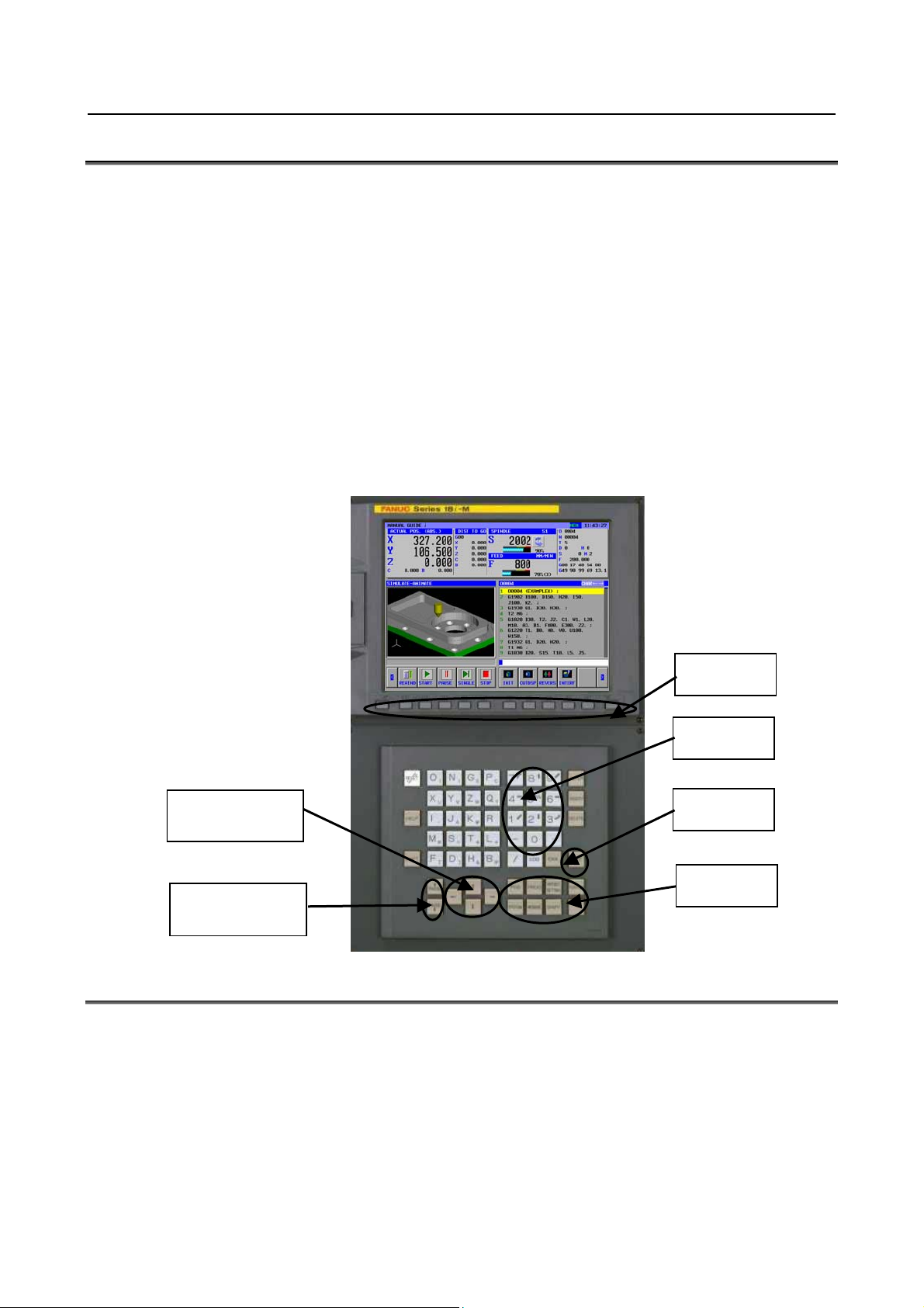
In this manual, the following conventions are used for keys.
(1) Function keys are represented by enclosing their names between the special characters < and >:
Example) <PROGRM>, <OFSET>
(2) The numbers to be input by Numeral keys are indicated as it is.
Example) 12.345
(3) Similarly to functions keys, the input (INPUT) and editing keys are represented by enclosing their
names between the special characters < and >:
Example) 12.345 <INPUT>, <ALTER>
(4) Soft-keys are enclosed in brackets [ ]:
Example) [LIST], [LINE]
(5) The cursor move keys are indicated by the following symbols :
Example) <↑>, <↓>, <←>, <→>
(6) The page change keys are indicated by the following symbols :
Example) <↑ PAGE>, <PAGE ↓>
Soft Keys
Numeral keys
Cursor move keys
(or cursor keys)
Page change keys
(or page keys)
INPUT key
Function keys
FORMAT OF PROGRAMS TO BE USED
The ISO code format, which is in wide use for CNC machine tools, is used on machining programs used
with MANUAL GUIDE i. In addition, G4-digit machining cycles are used to implement advanced
machining operations.
G4-digit machining cycles can be input and edited easily using a menu window, which enables machining
data to be entered interactively.
When a machining program is being edited, an address at which the cursor is placed is explained at the
bottom of the screen.
s-3
Page 6

SAFETY PRECAUTIONS B-63874EN/11
1. Word
The term “word” refers to a minimum unit in NC machining programs. It is represented using a
combination of an address (one of letters A to Z), some of digits 0 to 9, an arithmetic symbol (+ or -),
and/or a decimal point.
The “address” represents the meaning of numeric data, such as a machine movement axis
2. Cursor
The term “cursor” used with machining programs refers to a display portion where a string of
characters is shown against a yellow background. This portion is referred to as “cursor-selected
display portion”. This is the place where an actual editing action is made during machining program
editing.
Either of the following two items can be cursor-selected.
<1> 1 block
When the cursor is shifted to the beginning of the next block by pressing the cursor move key
<→>, the entire block is selected.
When the cursor is placed at the address of the beginning of a certain block, pressing the cursor
move key <←> causes the entire block to be selected.
When a block is already selected, pressing the cursor move key <↑> or <↓> causes the block,
respectively, following or preceding the block of interest to be selected.
<2> 1 word
When a whole block is selected, pressing the cursor move key <←> or <→> causes a word to
be selected. Each time the cursor move key <←> or <→> is pressed, a new word is selected.
When a word in a certain block is selected, pressing the cursor move key <↑> or <↓> causes
the same-number address in the block, respectively, following or preceding the block of interest
to be selected.
NOTE
1 On a screen where numeric data, such as offset data or cycle machining data, is
input directly, the term “cursor” refers to a data portion enclosed in a blue frame.
2 A data portion enclosed in a blue frame is referred to as “cursor-selected data
item”. Once numeric data is keyed in with numeric keys, pressing the <INPUT>
key causes the numeric data to be input as the data item of interest.
3 Pressing the cursor move key <←>, <↑>, <↓>, or <→> causes a new data item
to be selected.
s-4
Page 7

B-63874EN/11 PREFACE
PREFACE
This manual is configured as follows:
Explanations about the document contents
SAFETY PRECAUTIONS
Describes the rules you should observe so that you can safely use machines incorporating FANUC
MANUAL GUIDE i.
PREFACE
Explains how this document is configured. It also lists applicable CNC units and related documents.
Part I, “WHAT IS MANUAL GUIDE i?”
Describes the features of MANUAL GUIDE i.
Part II, “BASIC SCREEN AND OPERATION”
Describes the configuration of the MANUAL GUIDE i screen. It also explains all basic operations,
from creating machining programs in ISO code format to running machine tools using the programs.
Part III, “CONVENIENT FUNCTIONS”
Explains convenient functions that will help create and run programs.
Part IV, “MACHINING CYCLE”
Explains how to program machining cycles offered by MANUAL GUIDE i.
Part V, “MULTI-PATH LATHE FUNCTIONS (OPTION)”
Explains how to program functions for multipath lathes.
Part VI, “OTHER FUNCTIONS”
Describes the program coordinate system switching, tool management, and other functions usable
with MANUAL GUIDE i.
APPENDIX
Provides information (such as examples of creating and running programs, alarms, and parameter
setting) which machine operators can reference when operating MANUAL GUIDE i.
APPENDIX (FOR MACHINE TOOL BUILDER)
Provides information (such as MANUAL GUIDE i startup procedure and customization) which
machine tool builders will need in using MANUAL GUIDE i.
Applicable models
This manual can be used with the following models.
The abbreviated names may be used.
- FANUC Series 30i/31i/32i-MODEL A
Product name Abbreviation
FANUC Series 30i-MODEL A 30i –A Series 30i
FANUC Series 31i-MODEL A 31i –A
FANUC Series 31i-MODEL A5 31i –A5
FANUC Series 32i-MODEL A 32i –A Series 32i
- FANUC Series 30i/31i/32i-MODEL B
Product name Abbreviation
FANUC Series 30i-MODEL B 30i –B Series 30i
FANUC Series 31i-MODEL B 31i –B
FANUC Series 31i-MODEL B5 31i –B5
FANUC Series 32i-MODEL B 32i –B Series 32i
Series 31i
Series 31i
p-1
Page 8
PREFACE B-63874EN/11
NOTE
1 For an explanatory purpose, the following descriptions may be used according to
the types of path control used:
T series: For the lathe system
•
M series: For the machining center system
•
2 Unless otherwise stated, the model names Series 30i, Series 31i, and Series 32i
used in this document sometimes collectively refer to the models mentioned
above except for item 3 below.
3 Some functions described in this manual may not be applied to some products.
For details, refer to the DESCRIPTIONS (B-63942EN) related to applied CNC.
4 MANUAL GUIDE i is not available in Series 30i-MODEL A or MODEL B with 5
paths or over.
- FANUC Series 16i/18i/160i/180i/160is/180is-MODEL B
Product name Abbreviation
FANUC Series 16i-TB 16i-TB
FANUC Series 16i-MB 16i-MB
FANUC Series 160i-TB 160i-TB
FANUC Series 160i-MB 160i-MB
FANUC Series 160is-TB 160is-TB
FANUC Series 160is-MB 160is-MB
FANUC Series 18i-TB 18i-TB
FANUC Series 18i-MB5 18i-MB5
FANUC Series 18i-MB 18i-MB
FANUC Series 180i-TB 180i-TB
FANUC Series 180i-MB5 180i-MB5
FANUC Series 180i-MB 180i-MB
FANUC Series 180is-TB 180is-TB
FANUC Series 180is-MB5 180is-MB5
FANUC Series 180is-MB 180is-MB
FANUC Series 21i-TB 21i-TB
FANUC Series 21i-MB 21i-MB
FANUC Series 210i-TB 210i-TB
FANUC Series 210i-MB 210i-MB
FANUC Series 210is-TB 210is-TB
FANUC Series 210is-MB 210is-MB
Series 16i
Series 18i
Series 21i
NOTE
1 For an explanatory purpose, the following descriptions may be used according to
the types of path control used:
T series: For the lathe system
•
M series: For the machining center system
•
2 Unless otherwise stated, the model names Series 16i, Series 18i, and Series 21i
used in this document sometimes collectively refer to the models mentioned
above except for item 3 below.
3 Some functions described in this manual may not be applied to some products.
For details, refer to the DESCRIPTIONS (B-63532EN) related to applied CNC.
p-2
Page 9

B-63874EN/11 PREFACE
- FANUC Series 0i–MODEL F
Product name Abbreviation
FANUC Series 0i-TF 0i-TF
FANUC Series 0i-MF 0i-MF
Series 0i-F
- FANUC Series 0i–MODEL D
Product name Abbreviation
FANUC Series 0i-TD 0i-TD
FANUC Series 0i-MD 0i-MD
Series 0i-D
- FANUC Series 0i–MODEL C
Product name Abbreviation
FANUC Series 0i-TC 0i-TC
FANUC Series 0i-TTC 0i-TTC
FANUC Series 0i-MC 0i-MC
Series 0i-C
NOTE
1 For an explanatory purpose, the following descriptions may be used according to
the types of path control used:
T series: For the lathe system
•
M series: For the machining center system
•
2 Unless otherwise stated, the model names Series 0i used in this document
sometimes collectively refer to the models mentioned above except for item 3
below.
3 Some functions described in this manual may not be applied to some products.
For details, refer to the DESCRIPTIONS (B-64112EN, B-64302EN) related to
applied CNC.
Related manuals
- Manuals related to MANUAL GUIDE i
The table below lists manuals related to MANUAL GUIDE i.
Manual name Specification Number
OPERATOR’S MANUAL (Common to Lathe System/Machining Center System) B-63874EN *
OPERATOR’S MANUAL (For Machining Center System) B-63874EN-2
OPERATOR’S MANUAL (SET-UP GUIDANCE FUNCTIONS) B-63874EN-1
(*) In the table, this manual is marked with an asterisk (*).
- Manuals related to FANUC Series 30i/31i/32i-MODEL A
Manual name Specification Number
DESCRIPTIONS B-63942EN
CONNECTION MANUAL (HARDWARE)
CONNECTION MANUAL (FUNCTION)
OPERATOR’S MANUAL (Common to Lathe System/Machining Center System) B-63944EN
OPERATOR’S MANUAL (For Lathe System) B-63944EN-1
OPERATOR’S MANUAL (For Machining Center System) B-63944EN-2
MAINTENANCE MANUAL B-63945EN
PARAMETER MANUAL B-65950EN
B-63943EN
B-63943EN-1
p-3
Page 10
PREFACE B-63874EN/11
- Manuals related to FANUC Series 30i/31i/32i-MODEL B
Manual name Specification Number
DESCRIPTIONS B-64482EN
CONNECTION MANUAL (HARDWARE)
CONNECTION MANUAL (FUNCTION)
OPERATOR’S MANUAL (Common to Lathe System/Machining Center System) B-64484EN
OPERATOR’S MANUAL (For Lathe System) B-64484EN-1
OPERATOR’S MANUAL (For Machining Center System) B-64484EN-2
MAINTENANCE MANUAL B-64485EN
PARAMETER MANUAL B-64490EN
B-64483EN
B-64483EN-1
- Manuals related to FANUC Series 16i/18i/160i/180i/160is/180is-MODEL B
Manual name
DESCRIPTIONS B-63522EN
CONNECTION MANUAL (HARDWARE) B-63523EN
CONNECTION MANUAL (FUNCTION) B-63523EN-1
OPERATOR’S MANUAL (For Lathe System) B-63524EN
OPERATOR’S MANUAL (For Machining Center System) B-63534EN
MAINTENANCE MANUAL B-63525EN
PARAMETER MANUAL B-63530EN
Specification Number
- Manuals related to FANUC Series 0i–MODEL F
Manual name Specification Number
DESCRIPTIONS B-64602EN
CONNECTION MANUAL (HARDWARE) B-64603EN
CONNECTION MANUAL (FUNCTION) B-64603EN-1
OPERATOR’S MANUAL (Common to Lathe System/Machining Center System) B-64604EN
OPERATOR’S MANUAL (For Lathe System) B-64604EN-1
OPERATOR’S MANUAL (For Machining Center System) B-64604EN-2
MAINTENANCE MANUAL B-64605EN
PARAMETER MANUAL B-64610EN
- Manuals related to FANUC Series 0i–MODEL D
Manual name Specification Number
DESCRIPTIONS B-64302EN
CONNECTION MANUAL (HARDWARE) B-64303EN
CONNECTION MANUAL (FUNCTION) B-64303EN-1
OPERATOR’S MANUAL (Common to Lathe System/Machining Center System) B-64304EN
OPERATOR’S MANUAL (For Lathe System) B-64304EN-1
OPERATOR’S MANUAL (For Machining Center System) B-64304EN-2
MAINTENANCE MANUAL B-64305EN
PARAMETER MANUAL B-64310EN
START-UP MANUAL B-64304EN-3
- Manuals related to FANUC Series 0i–MODEL C
Manual name Specification Number
DESCRIPTIONS B-64112EN
CONNECTION MANUAL (HARDWARE)
CONNECTION MANUAL (FUNCTION)
Series 0i-TC OPERATOR’S MANUAL
Series 0i-MC OPERATOR’S MANUAL
Series 0i-TTC OPERATOR’S MANUAL
B-64113EN
B-64113EN-1
B-64114EN
B-64124EN
B-64284EN
p-4
Page 11

B-63874EN/11 PREFACE
Manual name Specification Number
MAINTENANCE MANUAL B-64115EN
PARAMETER MANUAL B-64120EN
p-5
Page 12

Page 13

B-63874EN/11 TABLE OF CONTENTS
TABLE OF CONTENTS
SAFETY PRECAUTIONS............................................................................s-1
DEFINITION OF WARNING, CAUTION, AND NOTE.............................................s-1
GENERAL WARNINGS AND CAUTIONS...............................................................s-1
OVERVIEW OF THIS MANUAL..............................................................................s-2
SYMBOLS USED....................................................................................................s-3
FORMAT OF PROGRAMS TO BE USED...............................................................s-3
PREFACE....................................................................................................p-1
I. WHAT IS MANUAL GUIDE i?
1 WHAT IS MANUAL GUIDE i?................................................................3
1.1 WHAT IS MANUAL GUIDE i?........................................................................3
1.2 MAIN FEATURES OF MANUAL GUIDE i .....................................................3
II. BASIC SCREEN AND OPERATION
1 BASIC SCREEN......................................................................................7
2 EDITING PROGRAMS..........................................................................10
2.1 PROGRAM WINDOW AND EDITING .........................................................10
2.2 CREATING MACHINING PROGRAMS.......................................................10
2.3 EDITING IN A PROGRAM LIST..................................................................11
2.3.1 Simultaneous Deletion of Multiple Programs ........................................................12
2.3.2 Managing Program List Folder (for Series 30i/31i/32i Only)................................12
2.3.2.1 What is displayed in the program list?............................................................... 12
2.3.2.2 Operations added to the program list window................................................... 13
2.3.2.3 Supporting data server operations .....................................................................13
2.4 SEARCHING FOR A MACHINING PROGRAM TO BE EDITED.................14
2.5 PROGRAM NUMBER O8-DIGIT FUNCTION..............................................14
2.6 BASIC EDITING OPERATIONS OF PART PROGRAM..............................14
2.6.1 Entering a Word (<INSERT> key) ........................................................................14
2.6.2 Modifying a Word (<ALTER> key) ......................................................................15
2.6.3 Modifying the Numeric Value of a Word (<ALTER> key)...................................15
2.6.4 Deleting a Word (<DELETE> key) .......................................................................15
2.6.5 Modifying a Block (<ALTER> key)......................................................................15
2.6.6 Deleting a Block (<DELETE> key).......................................................................15
2.6.7 Changing the Program Number (ALTER key).......................................................15
2.7 SEARCH (FORWARD AND BACKWARD)..................................................15
2.7.1 Simultaneous String Search Function of Multi Programs......................................16
2.7.1.1 Mode to use this function .................................................................................. 16
2.7.1.2 Program window where search is executed.......................................................16
2.7.1.3 Changing search mode....................................................................................... 16
2.7.1.4 Execute simultaneous string search of multi programs ..................................... 17
2.8 CUT.............................................................................................................17
2.9 COPY ..........................................................................................................18
2.10 PASTE.........................................................................................................18
2.11 DELETE.......................................................................................................18
c-1
Page 14

TABLE OF CONTENTS B-63874EN/11
2.12 KEY-IN PASTE............................................................................................18
2.13 REPLACING WORD....................................................................................19
2.13.1 Replacing a Word...................................................................................................19
2.13.2 Replace All Words .................................................................................................19
2.13.3 Replaced Words .....................................................................................................20
2.13.4 Note........................................................................................................................21
2.14 UNDO, REDO..............................................................................................22
2.15 MULTI PART PROGRAM EDITING FUNCTION
(For only Series30i /31i /32i /0i-F/0i-D)......................................................22
2.15.1 Start of Multi Part Program Editing Function........................................................22
2.15.2 Operation of Display Program Selection................................................................22
2.15.3 Display of Multi Part Program Editing Screen.......................................................23
2.15.4 Opening and Shutting of Program Window...........................................................24
2.15.5 Switching Target of Editing Program.....................................................................24
2.15.6 End of Multi Part Program Editing Function of Programs.....................................25
2.15.7 Operation of Switching to CNC Screen .................................................................25
2.15.8 Operation of Changing Path...................................................................................25
2.15.9 Operation of Changing Mode.................................................................................26
2.15.10 About the Maintenance of Displayed Program Information ..................................26
2.15.11 Restrictions.............................................................................................................26
2.16 M-CODE MENU...........................................................................................26
2.17 FIXED FORM SENTENCE INSERTION......................................................27
2.17.1 Fixed Form Sentence..............................................................................................27
2.17.2 Start Command.......................................................................................................28
2.17.3 End Command........................................................................................................29
2.18 REGISTERING FIXED FORM SENTENCES..............................................29
2.18.1 Registering a New Fixed Form Sentence...............................................................30
2.18.2 Modifying a Fixed Form Sentence.........................................................................30
2.18.3 Deleting a Fixed Form Sentence ............................................................................31
2.18.4 Initialization to Standard Fixed Form Sentences....................................................31
2.18.5 Extension of Fixed Form Sentences
(For only Series 30i/31i/32i-B, Series 0i-F/0i-D)...................................................32
2.18.5.1 Parameter...........................................................................................................32
2.19 BACKGROUND EDITING ...........................................................................32
2.19.1 Starting Background Editing..................................................................................32
2.19.2 Ending Background Editing...................................................................................32
2.19.3 Operations During Background Editing.................................................................33
2.20 NOTES ON CREATING PROGRAMS.........................................................33
2.20.1 General Notes on Machining Programs .................................................................33
3 MACHINING SIMULATION...................................................................34
3.1 EDITING WITH THE PROGRAM LIST........................................................34
3.2 SEARCHING FOR A SEQUENCE NUMBER IN A PROGRAM...................35
3.3 SELECTING A PROGRAM FOR MACHINING SIMULATION.....................35
3.4 REWINDING A PROGRAM.........................................................................35
3.5 SETTING OF DATA FOR MACHINING SIMULATION................................35
3.6 MACHINING SIMULATION DISPLAY.........................................................48
3.6.1 Machining Simulation (Tool Path) (for Series 0i-C/16i/18i/21i)...........................48
3.6.1.1 Starting and stopping simulation....................................................................... 49
3.6.1.2 Scaling, movement, and other operations.......................................................... 50
3.6.2 Machining Simulation (Animated Drawing) (FOR Series 0i-C /16i/18i/21i)........50
3.6.2.1 Starting and stopping machining simulation......................................................51
c-2
Page 15

B-63874EN/11 TABLE OF CONTENTS
3.6.2.2 Scaling, movement, and other operations.......................................................... 52
3.6.3 Machining Simulation (Tool Path Drawing) (for Series 0i-F/0i-D/ 30i/31i/32i) ...52
3.6.3.1 Starting and stopping machining simulation......................................................54
3.6.3.2 Scaling, movement, and other operations.......................................................... 55
3.6.4 Machining Simulation (Animated Drawing) (for Series 0i-F/0i-D/ 30i/31i/32i)...55
3.6.4.1 Starting and stopping machining simulation......................................................55
3.6.4.2 Scaling, movement, and other operations.......................................................... 56
3.6.5 Data Handled during Machining Simulation (for Series 0i-F/0i-D/ 30i/31i/32i)...56
3.6.6 Functions Operating Differently between Machining Simulation and Automatic
Operation (for Series 0i-F/0i-D/ 30i/31i/32i).........................................................57
3.6.6.1 Functions that cannot be used for machining simulation...................................57
3.6.6.2 Functions that can be used for machining simulation (M series) ...................... 58
3.6.7 Changing Workpiece Coordinate During Machining Simulation (Animation,
Tool Path Drawing)................................................................................................58
3.6.8 Machining Simulation Screen on 15 inch LCD (Tool Path)
(for Series 30i/31i/32i, Series 0i-F)........................................................................59
3.6.8.1 Operations at machining simulation screen....................................................... 59
3.6.8.2 Operations at drawing during machining screen ............................................... 59
3.7 CHECK Y AXIS VALUE AT THE MACHINING SIMULATION OF THE
TURNING CYCLE .......................................................................................60
3.8 A WARNING MESSAGE WHEN A RESIDUAL CUTTING PART
REMAINS....................................................................................................60
3.9 MACHINING SIMULATION SPEED CHANGE FUNCTION.........................60
3.9.1 Operation on Machining Simulation Screen ..........................................................60
3.10 BLANK CUTOUT DISPLAY IN ANIMATED SIMULATION..........................62
3.10.1 Operation................................................................................................................62
3.10.2 Available Blank Figures for Blank Cutout Display ...............................................62
3.11 DISPLAYING MACHINING TIME................................................................63
3.11.1 Format of Machining Time Data............................................................................63
3.11.2 Operation for Inserting Machining Time ...............................................................63
3.11.3 Display Machining Time........................................................................................64
3.12 LARGE WINDOW DISPLAY OF MACHINING SIMULATION (ANIMATED
DRAWING) (For Series 30i/31i/32i–B only) ................................................64
3.12.1 Changing Window Size of Machining Simulation (Animated Drawing) ..............64
3.12.2 Restrictions on Large Window Display .................................................................65
3.13 2 WINDOWS MACHINING SIMULATION
(For only Series 0i-F/30i/31i/32i–B).............................................................65
3.13.1 Changing Window of Machining Simulation.........................................................65
3.13.2 Selecting Active Window.......................................................................................66
3.13.3 Restrictions on 2 Windows Display.......................................................................66
3.14 NOTES........................................................................................................66
3.14.1 Notes on Machining Simulation.............................................................................66
3.14.2 Tool size in Machining Simulation ........................................................................67
4 PROGRAM OPERATION......................................................................68
4.1 SELECTING A PROGRAM FOR OPERATION...........................................68
4.2 REWINDING A PROGRAM.........................................................................68
4.3 DISPLAYING THE DRAWING-DURING-MACHINING................................69
4.3.1 Program Selection Operation and Other Operations in Drawing during
Machining...............................................................................................................70
4.3.2 Selecting Whether to Display the Tool Path or Not in Drawing during
Machining...............................................................................................................70
c-3
Page 16

TABLE OF CONTENTS B-63874EN/11
4.3.3 Scaling, Movement, and Other Operations in Drawing during Machining............70
4.4 CHANGING THE CURRENT POSITION DISPLAY.....................................72
4.5 PRESETTING RELATIVE COORDINATES ................................................72
4.6 NEXT-BLOCK DISPLAY FUNCTION..........................................................72
4.7 FEEDRATE DISPLAY .................................................................................73
4.8 DISPLAYING 3-DIMENSIONAL INTERFERENCE CHECK STATUS (FOR
Series 0i-F/30i/31i/32i ONLY)....................................................................73
4.9 DISPLAYING THE ROTATION SPEED OF A SERVO MOTOR-DRIVEN
MILLING AXIS.............................................................................................73
4.9.1 Conditions for Using This Function.......................................................................74
4.9.2 About the “SPINDLE” Display Block ...................................................................74
4.9.2.1 Path 1 display window (10.4-inch screen)......................................................... 74
4.9.2.2 Path 1 display window (15-inch screen)............................................................ 75
4.9.2.3 Simultaneous multipath display window (10.4-inch screen).............................76
4.9.2.4 Simultaneous multipath display window (15-inch screen)................................77
4.9.2.5 Machining simulation and NC statement conversion windows
(10.4-inch screen).............................................................................................. 78
4.9.2.6 Machining simulation and NC statement conversion windows
(15-inch screen)................................................................................................. 78
4.9.2.7 Re-threading window ........................................................................................ 78
4.9.3 “CURRENT POSITION” Display Block...............................................................79
4.9.4 “FEED” Display Block ..........................................................................................79
4.9.5 Details of Actual Rotation Speed Shown in the SPINDLE Display Block............79
4.9.6 Details of Load Ratio (%) Shown in the SPINDLE Display Block ....................... 80
4.10 DISPLAYING THE SPINDLE-POSITION AND STANDBY-POSITION
TOOL NUMBERS (FOR Series 30i/31i/32i ONLY) .....................................81
4.10.1 Displaying the Spindle-Position Tool Number ......................................................81
4.10.2 Displaying the Standby-Position Tool Number .....................................................81
4.11 G54.4 MODAL DISPLAY.............................................................................81
4.11.1 DETAIL..................................................................................................................82
4.11.2 NOTE .....................................................................................................................82
4.12 COMMENT DISPLAY DURING MACHINING..............................................83
4.12.1 Format of Comment Display G code G2900..........................................................83
4.12.2 Notes.......................................................................................................................84
4.13 OPERATION RESTART CONFIRMATION FUNCIOTN AFTER EDITING
PROGRAM (FOR Series 30i/31i/32i)..........................................................84
4.13.1 Operation Restart Confirmation Screen .................................................................84
4.13.2 Editing Function during Single Block Stop ...........................................................84
4.13.3 Operation Restart Confirmation in Multi Path System ..........................................85
4.13.4 Parameter................................................................................................................85
5 EDITING AND OPERATION OF MDI PROGRAMS..............................86
6 MANUAL OPERATION.........................................................................87
7 SETTING THE WORKPIECE COORDINATE DATA............................88
7.1 SOFT KEY [MEASUR].................................................................................88
7.2 SOFT KEY [+INPUT]...................................................................................88
7.3 CALCULATING METHOD OF MEASURING OF SETTING WORKPIECE
COORDINATE DATA (for Series 0i-F/0i-D/30i/31i/32i)...............................89
7.3.1 Outline....................................................................................................................89
7.3.1.1 In case of Series 0i-D......................................................................................... 89
c-4
Page 17

B-63874EN/11 TABLE OF CONTENTS
7.3.1.2 In case of Series 0i-F/30i/31i/32i-A/B...............................................................90
7.3.2 Parameter Setting ...................................................................................................90
8 SETTINGS RELATED TO TOOLS........................................................91
8.1 SETTING TOOL OFFSET DATA.................................................................91
8.1.1 Softkeys Icons for the Direction of the Imaginary Tool Nose ...............................91
8.1.1.1 How to specify icons ......................................................................................... 91
8.1.1.2 If program coordinate system/offset memory switching is enabled ..................92
8.1.2 Soft Key [MEASUR] .............................................................................................92
8.1.3 Soft Key [+INPUT]................................................................................................92
8.1.4 Soft Key [INP.C.]...................................................................................................92
8.2 SPECIFYING TOOL FIGURE DIMENSION DATA......................................93
8.2.1 Overview................................................................................................................93
8.2.2 Setting of Tool Type ..............................................................................................93
8.2.3 Editing of Tool Name.............................................................................................94
8.2.4 Setting of Tool Set..................................................................................................94
8.2.5 Setting of Tool Data ...............................................................................................94
8.2.6 Cutting Edge Angle................................................................................................95
8.2.7 Initializing of Tool Data.........................................................................................96
8.2.8 Displaying Tool Icons ............................................................................................96
8.2.9 Shortcut to the Tool Figure Dimension Data Setting Window ..............................97
8.3 TOOL INFORMATION DISPLAY.................................................................97
8.3.1 Displaying Screen...................................................................................................97
8.3.2 Tool Information Display.......................................................................................98
8.3.3 Notes when Commanding Offset Number by D Code...........................................98
8.4 COMBINING A TOOL DATABASE WITH THE TOOL MANAGEMENT
FUNCTION..................................................................................................98
8.4.1 Tool Management Data Window ...........................................................................98
8.4.2 Tool Management Data Tab...................................................................................99
8.4.2.1 Tool management data....................................................................................... 99
8.4.2.2 Spindle rotation speed and feedrate...................................................................99
8.4.2.3 Tool offset........................................................................................................100
8.4.2.4 Customization data..........................................................................................100
8.4.3 Customizing Tool Management Data Displays....................................................100
8.4.4 Magazine Management Table Tab .......................................................................100
8.4.5 Tool Offset Tab ....................................................................................................101
8.4.6 Tool Information Tab...........................................................................................101
8.4.7 Outputting Tool Management Data to the Memory Card ....................................101
8.4.8 Inputting Tool Management Data from the Memory Card ..................................101
III. CONVENIENT FUNCTIONS
1 CONTOUR PROGRAMMING..............................................................105
2 MEMORY CARD INPUT/OUTPUT FUNCTION..................................106
2.1 MEMORY CARD INPUT/OUTPUT OF PROGRAM...................................106
2.1.1 Memory Card Input/Output Screen of Program...................................................106
2.1.2 Memory Card Output Operation for Program......................................................107
2.1.3 Memory Card Input Operation for Program.........................................................108
2.1.4 File Format Allowed for Memory Card Input/Output..........................................109
2.1.5 Notes.....................................................................................................................109
2.2 MEMORY CARD INPUT/OUTPUT OF TOOL DATA.................................110
2.2.1 Memory Card Input/Output Screen of Tool Data.................................................110
2.2.2 Memory Card Output Operation for Tool Data....................................................110
c-5
Page 18

TABLE OF CONTENTS B-63874EN/11
2.2.3 Memory Card Input Operation for Tool Data ......................................................110
2.2.4 Data Format..........................................................................................................110
2.3 MEMORY CARD INPUT/OUTPUT OF OFFSET DATA (FOR Series
16i/18i/21i/30i/31i/32i)...............................................................................111
2.3.1 Output Operation..................................................................................................111
2.3.2 Input Operation.....................................................................................................112
2.3.3 Notes.....................................................................................................................112
2.4 MEMORY CARD INPUT/OUTPUT OF FIXED FORM SENTENCES........112
2.4.1 Memory Card Input/Output Screen of Fixed Form Sentences.............................112
2.4.2 Output Operation for Fixed Form Sentences........................................................113
2.4.3 Input Operation for Fixed Form Sentences ..........................................................113
2.4.4 Format of Fixed Form Sentences .........................................................................113
3 USB MEMORY INPUT/OUTPUT FUNCTION (for Series 0i-F/0i-D,
30i/31i/32i-B)......................................................................................114
3.1 USB MEMORY INPUT/OUTPUT OF PROGRAM .....................................114
3.1.1 USB Memory Input/Output Screen of Program...................................................114
3.1.2 USB Memory Output Operation for Program......................................................115
3.1.3 USB Memory Input Operation for Program.........................................................116
3.1.4 File Format Allowed for USB Memory Input/Output..........................................116
3.1.5 Notes.....................................................................................................................117
4 PROGRAM RESTART FUNCTION.....................................................118
4.1 RESTART METHOD .................................................................................118
4.1.1 Soft-key [P TYPE] ...............................................................................................118
4.1.2 Soft-key [Q TYPE]...............................................................................................119
4.2 PROGRAM RESTART IN MACHINING CYCLE (For only
Series30i/31i/32i-A/B, 0i-F/0i-D) ...............................................................119
5 CALCULATOR FUNCTION ................................................................120
5.1 APPLICATIONS.........................................................................................120
5.2 CALCULATION METHODS.......................................................................120
5.3 TRIGONOMETRIC FUNCTIONS (SINE, COSINE, TANGENT, ARCSINE,
ARCCOSINE, ARCTANGENT)..................................................................120
5.4 SQUARE ROOT........................................................................................121
5.5 EXPONENTIAL FUNCTIONS....................................................................121
5.6 LOGARITHMIC FUNCTIONS (COMMON LOGARITHM, NATURAL
LOGARITHM)............................................................................................121
5.7 ABSOLUTE VALUE...................................................................................121
5.8 ROUNDING...............................................................................................122
5.9 DISCARDING............................................................................................122
5.10 CIRCLE RATIO..........................................................................................122
6 SHORTCUT KEY OPERATIONS........................................................123
6.1 SHORTCUTS FOR VARIOUS CONFIRMATION OPERATIONS..............123
6.2 SHORTCUTS FOR RANGE SELECTION.................................................123
6.3 SHORTCUTS FOR COPY OPERATION...................................................123
6.4 SHORTCUTS FOR CUT OPERATION .....................................................123
6.5 SHORTCUTS FOR THE BASE SCREEN SOFT KEYS ............................123
6.6 SHORTCUT FOR STARTING THE CYCLE CHANGE SCREEN..............124
c-6
Page 19

B-63874EN/11 TABLE OF CONTENTS
6.7 SHORTCUTS FOR THE MENU SELECTION SCREEN...........................124
6.8 SHORTCUTS FOR THE REGULAR PROGRAM INSERTION SCREEN..124
6.9 SHORTCUTS FOR THE M CODE INSERTION SCREEN........................124
6.10 SHORTCUTS FOR THE PROGRAM LIST SCREEN................................124
6.11 INVALIDATION OF SHORTCUT KEY OPERATIONS ..............................125
6.11.1 Operation of Shortcut Key ...................................................................................125
6.12 SHORTCUTS FOR THE PROGRAM CREATION SCREEN.....................125
6.13 SHORTCUTS FOR THE COMMENT EDITING SCREEN.........................125
6.14 SHORTCUTS FOR THE SEARCH SCREEN............................................125
6.15 SHORTCUTS FOR THE CYCLE INPUT SCREEN ...................................125
6.16 SHORTCUT FOR THE WORKPIECE COORDINATE SYSTEM SETTING
SCREEN....................................................................................................126
6.17 SHORTCUT FOR THE TOOL OFFSET SETTING SCREEN....................126
6.18 SHORTCUTS FOR THE REGULAR PROGRAM REGISTRATION
SCREEN....................................................................................................126
6.19 SHORTCUTS FOR THE CREATION SCREEN FOR REGULAR
PROGRAM REGISTRATION ....................................................................126
6.20 SHORTCUTS FOR THE ALTER SCREEN FOR REGULAR PROGRAM
REGISTRATION........................................................................................126
6.21 SHORTCUTS FOR THE PRESET SCREEN.............................................127
6.22 SHORTCUT FOR THE MEASUREMENT RESULT SCREEN ..................127
6.23 SHORTCUT FOR THE MANUAL MEASUREMENT SCREEN..................127
6.24 SHORTCUT FOR VARIOUS SETTING SCREENS ..................................127
6.25 SHORTCUTS FOR THE FREE FIGURE MAIN SCREEN.........................127
6.26 SHORTCUTS FOR THE FREE FIGURE INPUT SCREEN.......................127
6.27 SHORTCUTS FOR THE FREE FIGURE CREATION SCREEN ...............128
7 INPUT OF DIRECTION ALONG THE LAYOUT OF NUMERIC
KEYS...................................................................................................129
8 HELP SCREEN ...................................................................................130
9 OPERATION NAVIGATING FUNCTION ............................................131
9.1 START METHOD FOR OPERATION NAVIGATING.................................131
9.1.1 First Method of Start (“SELECT NAVIGATION” window is displayed)...........131
9.1.2 Second Method of Start (“SELECT NAVIGATION” window isn’t displayed)..131
9.2 OPERATION WHILE NAVIGATION IS EFFECTIVE.................................132
9.3 THE METHOD TO FINISH OPERATION NAVIGATING...........................132
9.4 OPERATION WHEN STANDARD OPERATION NAVIGATING DATA
ARE USED ................................................................................................132
10 ADVANCED GUIDANCE FUNCTION
(for only Series 0i-F/30i/31i/32i-B) ...................................................134
10.1 DECOMPOSED CYCLE DISPLAY............................................................134
10.1.1 Method of Displaying the Decomposed Cycle Display Screen ...........................134
10.1.2 Condition..............................................................................................................135
10.1.3 Restriction ............................................................................................................135
10.2 INPUT DATA CHECK BY SIMULATION...................................................135
10.2.1 Condition..............................................................................................................136
c-7
Page 20

TABLE OF CONTENTS B-63874EN/11
10.2.2 Operational Procedure..........................................................................................136
10.2.3 Available Screen...................................................................................................136
10.2.4 Execution Range of Input Data Check by Simulation..........................................137
10.3 HELP WINDOW ACCORDING TO EACH SCREEN.................................138
10.3.1 Outline..................................................................................................................138
10.3.2 Condition..............................................................................................................139
10.3.3 Restriction ............................................................................................................139
10.4 COOPERATION WITH ANIMATED SOFTWARE THAT IS OPERATED
WITH PANEL i...........................................................................................139
10.4.1 Outline..................................................................................................................139
10.4.2 Condition..............................................................................................................139
10.4.3 Operation..............................................................................................................141
10.4.4 Restriction ............................................................................................................142
IV. MACHINING CYCLE
1 OVERVIEW .........................................................................................145
1.1 SELECTING A MACHINING CYCLE TYPE ..............................................145
1.2 ENTERING MACHINING CYCLE DATA ...................................................146
1.3 SELECTING FIGURES .............................................................................147
1.4 ENTERING FIXED FORM FIGURE DATA................................................149
1.5 ENTERING ARBITRARY FIGURE DATA..................................................150
1.6 CHANGING MACHINING CYCLE AND FIGURE DATA ...........................152
1.7 NOTES ON CREATING PROGRAMS.......................................................152
2 TURNING CYCLE ...............................................................................154
2.1 HOLE MACHINING (WORKPIECE ROTATION).......................................157
2.1.1 Machining Command...........................................................................................157
2.1.2 Specifying Pecking Clearance of Drill Cycle for Lathe in Input Window
(for only Series 30i/31i/32i-A/B, 0i-TF/0i-TD) ...................................................163
2.1.2.1 Parameter setting to use this function.............................................................. 163
2.1.2.2 Format of drill cycle ........................................................................................ 163
2.2 TURNING ..................................................................................................164
2.2.1 Machining Command...........................................................................................164
2.2.2 Arbitrary Figure (ZX Plane).................................................................................187
2.2.3 Conical Boring Cycle ...........................................................................................189
2.2.4 Optimization of the Cutting Direction in Finish Turning.....................................196
2.2.5 Go past amount in End Face Finishing.................................................................202
2.2.6 Continuous Machining of Roughing and Finishing .............................................203
2.2.7 Improvement of Excessive Amount of Travel in Turning Cycle.........................204
2.2.7.1 Target machining cycle.................................................................................... 204
2.2.7.2 Condition that this function is enabled ............................................................204
2.2.7.3 Example of machining.....................................................................................204
2.2.8 The Restriction of Turning Cycle When Input Values of Z-axis and X-axis
Clearances are Different.......................................................................................205
2.2.9 Restrictions...........................................................................................................205
2.3 TURNING GROOVING..............................................................................207
2.3.1 Machining Cycle ..................................................................................................207
2.3.2 Restrictions on Target Figures..............................................................................216
2.3.3 Fixed Form Figure (ZX Plane).............................................................................217
2.3.4 Turning Groove Cycle by Using Button Tool......................................................223
2.3.5 Automatic Adjustment of Escape Amount for Turning Grooving Cycle.............223
2.3.5.1 Machining cycles.............................................................................................223
c-8
Page 21

B-63874EN/11 TABLE OF CONTENTS
2.3.5.2 Tool path.......................................................................................................... 224
2.4 THREADING..............................................................................................225
2.4.1 Machining Command...........................................................................................225
2.4.2 Fixed Form Figure................................................................................................229
2.5 REAR END FACING BY TURNING...........................................................235
2.6 RESIDUAL MACHINING BY TURNING ....................................................236
2.6.1 Outline of the Residual Machining Cycle ............................................................236
2.6.2 Cycle Selection Screen.........................................................................................237
2.6.3 Cycle Input Screen ...............................................................................................237
2.6.4 Motion of Outer Surface Residual Roughing (G1160) ........................................238
2.6.5 Motion of Machining Other than Outer Surface Residual Roughing (G1160) ....242
2.6.6 Finish Turning Using G41/G42............................................................................242
2.7 POLYGON TURNING CYCLE...................................................................243
2.7.1 Input Items of Polygon Turning Cycle.................................................................243
2.7.2 Inserting Polygon Turning Cycle Command........................................................244
2.7.3 Tool Path of Polygon Turning..............................................................................245
2.7.4 Tool Kind Setting.................................................................................................247
2.7.5 Direction of Imaginary Tool Nose Setting ...........................................................247
2.7.6 Simulation during Polygon Turning Cycle ..........................................................247
3 C-AXIS AND A-AXIS MACHINING CYCLE ........................................248
3.1 C-AXIS AND A-AXIS GROOVING.............................................................249
3.1.1 Machining Command...........................................................................................249
3.1.2 Figure Blocks for C-axis and A-axis Grooving....................................................250
3.2 CYCLE RETRACT MOTION......................................................................254
3.3 C-AXIS MACHINING WITH ROTATION AXIS...........................................254
3.3.1 Support for C-Axis Machining with Rotation Axis .............................................254
3.4 C-AXIS AND A-AXIS CLAMPING M CODE OUTPUT...............................255
3.4.1 Outline..................................................................................................................255
3.4.2 Specifying the Clamping Method.........................................................................256
3.4.3 Value of M Code Output......................................................................................256
3.4.4 Distinction between Main and Sub Spindle .........................................................256
3.4.5 Position of M Code Output (When Hard Clamping is Selected) .........................256
3.4.6 Position of M Code Output (When Soft Clamping is Selected)...........................259
3.4.7 Position of M Code Output (When Suppression of Clamp Output is Selected)...260
4 MILLING..............................................................................................261
4.1 HOLE MACHINING ...................................................................................269
4.1.1 Machining Command (Tool Rotation: M Series).................................................269
4.1.2 Machining Command (Tool Rotation: T Series)..................................................277
4.1.3 Figure (XY Plane) ................................................................................................280
4.1.4 Figure (YZ/XC Plane)..........................................................................................284
4.1.5 Specifying Pecking Clearance / Return Amount of Drill Cycle for Machining
Center in Input Window (for only Series 30i/31i/32i-A/B, 0i-MF/0i-MD).........286
4.1.5.1 Parameter setting to use this function.............................................................. 286
4.1.5.2 Format of drill cycle ........................................................................................ 287
4.1.6 C axis Hole on End Face (Random Points) - Cartesian Coordinates Input
Cycle.....................................................................................................................287
4.1.6.1 Input items of C axis hole on end face (random points) - cartesian
coordinates (G1574)........................................................................................287
4.1.7 C axis Hole on End face (GRID) - Cartesian Coordinates Input Cycle (For only
Series 30i/31i/32iB, 0i-F/0i-D).............................................................................288
4.1.7.1 Input items of C-axis hole on end face (Grid) – cartesian coordinates
(G1576)............................................................................................................288
c-9
Page 22

TABLE OF CONTENTS B-63874EN/11
4.2 FACING.....................................................................................................289
4.2.1 Machining Command...........................................................................................289
4.2.2 Fixed Form Figure Blocks (XY Plane) ................................................................292
4.2.3 Fixed Form Figure (YZ Plane, XC Plane)............................................................294
4.2.4 Arbitrary Figure (XY Plane) ................................................................................295
4.2.5 Arbitrary Figure (YZ/XC/ZC/XA Plane) .............................................................295
4.3 CONTOURING..........................................................................................296
4.3.1 Machining Command...........................................................................................296
4.3.2 Fixed Form Figure (XY Plane).............................................................................310
4.3.3 Fixed Form Figure (YZ/XC Plane) ......................................................................311
4.3.4 Arbitrary Figure (XY Plane) ................................................................................312
4.3.5 Arbitrary Figure (YZ/XC/ZC/XA Plane) .............................................................313
4.4 EMBOSS MACHINING..............................................................................314
4.4.1 Machining Command...........................................................................................315
4.4.2 Arbitrary Figure (XY Plane) ................................................................................318
4.4.3 Arbitrary Figure (YZ/XC/ZC/XA plane) .............................................................319
4.5 POCKETING..............................................................................................320
4.5.1 Machining Command...........................................................................................320
4.5.2 Improvement of Checking Cutting Condition for Pocketing (Rough) and
Emboss Machining (Rough).................................................................................330
4.5.2.1 PARAMETER................................................................................................. 330
4.5.3 Fixed Form Figure (XY Plane).............................................................................330
4.5.4 Fixed Form Figure (YZ/XC Plane) ......................................................................331
4.5.5 Arbitrary Figure (XY Plane) ................................................................................332
4.5.6 Arbitrary Figure (YZ/XC/ZC/XA Plane) .............................................................333
4.5.7 Pocket Residual Machining Cycle (for only Series 30i/31i/32i-B, 0i-F/0i-D).....334
4.5.7.1 Outline.............................................................................................................334
4.5.7.2 Condition.........................................................................................................334
4.5.7.3 Operation.........................................................................................................334
4.5.7.4 Format of pocket residual machining cycle command ....................................335
4.5.7.5 Tool path.......................................................................................................... 336
4.5.7.6 Restrictions...................................................................................................... 337
4.6 GROOVING...............................................................................................339
4.6.1 Machining Command...........................................................................................339
4.6.2 Fixed Form Figure (XY Plane).............................................................................348
4.6.3 Fixed Form Figure (YZ/XC Plane) ......................................................................350
4.6.4 XC-plane Circumferential Groove Figure............................................................351
4.6.5 Arbitrary Figure (XY Plane) ................................................................................354
4.6.6 Arbitrary Figure (YZ/XC/ZC/XA Plane) .............................................................355
4.7 ENGRAVING CYCLE................................................................................356
4.7.1 Operation..............................................................................................................356
4.7.2 Input Item.............................................................................................................357
4.7.3 Enable Characters.................................................................................................359
4.7.4 Format of G4 Digit Cycle for Engraving Cycle ...................................................359
4.7.5 Tool Path of Engraving Cycle..............................................................................359
4.7.6 Restrictions...........................................................................................................360
4.8 THREAD MILLING CYCLE........................................................................361
4.8.1 Screens and Operations ........................................................................................361
4.8.2 Input Items of Thread Milling..............................................................................362
4.8.3 Specifiable Combinations of Figure.....................................................................363
4.8.4 Tool Kind .............................................................................................................363
4.8.5 Basic Motions of Tool..........................................................................................363
4.8.6 Machining Type ...................................................................................................364
4.8.7 Pattern of Tool Path..............................................................................................365
c-10
Page 23

B-63874EN/11 TABLE OF CONTENTS
4.8.8 Tool Path (Machining Type 1) .............................................................................365
4.8.9 Tool Path (Machining Type 2) .............................................................................366
4.8.10 Tool Path (Machining Type 3).............................................................................367
4.8.11 Machining Simulation Screen ..............................................................................368
4.8.12 Parameters............................................................................................................368
4.9 OUTER THREAD MILLING CYCLE..........................................................369
4.9.1 Machining Types..................................................................................................369
4.9.2 Method of Program Creation................................................................................370
4.9.3 Outer Thread Milling Cycle Command................................................................371
4.9.4 Tool Type.............................................................................................................372
4.9.5 Machining Simulation..........................................................................................372
4.9.6 Drawing-During-Machining.................................................................................373
4.9.7 Parameters............................................................................................................373
4.9.8 Alarms..................................................................................................................373
4.10 REAR END FACING BY MILLING.............................................................375
4.10.1 Rear End Facing...................................................................................................375
4.11 MIRROR / ROTATION / SCALING / FIGURE COPY COMMAND.............376
4.11.1 Coordinate Conversion (Mirror Image)................................................................377
4.11.2 Coordinate Conversion (Rotation) .......................................................................377
4.11.3 Scaling..................................................................................................................378
4.11.4 Figure Copy (Rotation Copy/ Parallel Copy).......................................................379
4.11.5 Parameter..............................................................................................................380
4.12 COORDINATE SYSTEM CONVERSION CYCLE.....................................381
4.12.1 Supportable Machine Configuration ....................................................................381
4.12.2 Slant Face Machining Command (Coordinate Conversion).................................382
4.13 TILTED WORKING PLANE INDEXING FUNCTION (FOR Series 30i/31i,
Series 0i-MF/0i-MD)..................................................................................384
4.13.1 Operation..............................................................................................................384
4.13.2 Tilted Working Plane Input Screen by Euler’s Angle..........................................385
4.13.3 Tilted Working Plane Input Screen by Roll-Pitch-Yaw.......................................386
4.13.4 Tilted Working Plane Input Screen by Three Points............................................386
4.13.5 Tilted Working Plane Input Screen by Two Vectors ...........................................387
4.13.6 Tilted Working Plane Input Screen by Projection Angles ...................................388
4.13.7 Tilted Working Plane Input Screen by Tool Axis Direction................................388
4.13.8 Tilted Working Plane Input Screen by Tilted Plane Cancel.................................388
4.13.9 Restriction of Machining Simulation ................................................................... 389
4.14 MILLING BY ROTATING A WORKPIECE ABOUT THE Y-AXIS...............389
4.14.1 Machining Type ...................................................................................................389
4.14.2 Figure ...................................................................................................................390
4.14.3 Machining Simulation..........................................................................................392
5 ENTERING ARBITRARY FIGURES...................................................393
5.1 ENTERING ARBITRARY FIGURE DATA..................................................393
5.1.1 Arbitrary Figures for the XY Plane......................................................................394
5.1.2 Arbitrary Figures for the YZ Plane ......................................................................399
5.1.3 Arbitrary Figures for the Polar Coordinate Interpolation Plane (XC Plane)........400
5.1.4 Arbitrary Figures for the Cylindrical Surface (ZC Plane)....................................401
5.1.5 Arbitrary Figures for Turning (ZX Plane)............................................................401
5.2 ARC SPECIFICATION BY CENTRAL ANGLE..........................................407
5.2.1 Operations ............................................................................................................407
5.2.2 Input Items............................................................................................................408
5.2.3 Enable Arbitrary Figures......................................................................................408
c-11
Page 24

TABLE OF CONTENTS B-63874EN/11
5.3 ENLARGEMENT AND REDUCTION ON THE ARBITRARY FIGURE
INPUT SCREEN........................................................................................408
5.3.1 Machining Simulation Screen ..............................................................................409
5.3.2 Arbitrary Figure Input Screen ..............................................................................409
5.3.3 Screen for Drawing during Machining.................................................................409
5.4 GROUPING ARBITRARY FIGURE PROGRAMS .....................................409
5.4.1 Group Range Selection Commands......................................................................409
5.4.2 Automatic Insertion of Group Range Selection Commands ................................410
5.5 ARBITRARY FIGURE COPY FUNCTIONS...............................................410
5.5.1 Selecting an Arbitrary Figure Copy Function ......................................................410
5.5.2 Copy Condition Input Screen...............................................................................410
5.5.3 Executing Arbitrary Figure Copy Operation........................................................411
5.5.4 Figure after Arbitrary Figure Copy Execution .....................................................412
5.6 EDITING AN ARBITRARY FIGURE SUBPROGRAM ...............................412
5.6.1 Editing..................................................................................................................412
5.6.2 Warning................................................................................................................413
5.7 SAVING SUBPROGRAMS........................................................................413
5.7.1 Saving a New Subprogram...................................................................................414
5.7.2 Saving an Existing Subprogram...........................................................................414
5.8 SELECTING A RANGE OF AN ARBITRARY FIGURE .............................415
5.8.1 G Code for Selecting a Range ..............................................................................415
5.8.2 Basic Operation....................................................................................................416
5.8.3 Machining of a Divided Area...............................................................................419
5.9 BLANK CONTOUR CHANGING FUNCTION OF TURNING FIGURE ......423
5.9.1 Usable Cycle.........................................................................................................423
5.9.2 Unusable Cycle.....................................................................................................424
5.9.3 Necessary Parameter Setting ................................................................................424
5.9.4 Operation..............................................................................................................424
5.9.4.1 Window for selection of turning figure range ................................................. 424
5.9.4.2 Window for selection of blank contour range ................................................. 424
5.9.4.3 Window for specification of arbitrary point....................................................425
5.9.4.4 Window for specification arbitrary angle........................................................ 425
5.9.4.5 Delete of division point and division angle of blank contour..........................426
5.9.4.6 Initialize of division point and division angle of blank contour...................... 426
5.9.4.7 G-code format of division point and division angle........................................426
5.9.5 Modification of Cutting Area in Machining Cycle ..............................................427
5.9.6 Restriction ............................................................................................................428
5.10 REUSING ARBITRARY FIGURES............................................................432
5.10.1 Calling an Arbitrary Figure..................................................................................432
5.10.2 Selecting a Subprogram........................................................................................432
5.11 REUSING A BLANK FIGURE AS AN ARBITRARY FIGURE....................433
5.11.1 Basic Operation....................................................................................................433
5.11.2 Reusable Blank Figures........................................................................................433
5.11.3 Conditions of Blank Figure Data for Reuse.........................................................433
5.12 AUTOMATIC BLANK ELEMENT CONNECTION FUNCTION...................434
5.12.1 Blank Element Connection Soft Key ...................................................................434
5.12.2 Soft Keys for Selecting a Blank Connection Figure ............................................434
5.13 EXPANDED ARBITRARY FIGURE ELEMENT NUMBER
(FOR Series 30i/31i/32i)............................................................................435
5.13.1 Restrictions...........................................................................................................435
5.14 DRAWING OF ARBITRARY FIGURE ON SUB-PROGRAM LIST
SCREEN....................................................................................................435
c-12
Page 25

B-63874EN/11 TABLE OF CONTENTS
5.14.1 Display Sub-Program List Screen........................................................................435
5.14.2 Available Drawing Figure....................................................................................436
6 NC PROGRAM CONVERSION FUNCTION.......................................437
6.1 OVERVIEW ...............................................................................................437
6.2 BASIC OPERATION..................................................................................438
6.3 RESTRICTIONS........................................................................................439
6.4 OMITTING MODAL COMMANDS IN NC PROGRAM CONVERSION......442
6.4.1 Omissible Modal Commands ...............................................................................442
6.4.2 Specifications for Omitting Modal Commands....................................................442
6.5 SUPPRESSING SUBPROGRAM EXPANSION IN NC PROGRAM
CONVERSION...........................................................................................443
6.5.1 Restriction ............................................................................................................445
6.6 CONVERSION OF G41/G42 COMMAND BY NC PROGRAM
CONVERSION (WITH SUBPROGRAM DECOMPOSITION)
(for only Series 30i/31i/32i-B, 0i-F/0i-D)....................................................445
6.6.1 Parameter Setting for Use.....................................................................................445
6.6.2 Restriction ............................................................................................................445
7 ADDRESS R OUTPUT FOR G02/G03 IN MACHINING CYCLE
(for Series 30i/31i/32i-A/B, 0i-F/0i-D) ...............................................449
7.1 CONDITION ..............................................................................................449
7.2 RESTRICTIONS........................................................................................449
V. MULTI-PATH LATHE FUNCTIONS (OPTION)
1 OVERVIEW .........................................................................................453
2 CHANGING BETWEEN PATHS.........................................................454
2.1 CHANGING BY A SOFT-KEY ...................................................................454
2.2 CHANGING BY A SIGNAL........................................................................454
2.3 IMPROVEMENT OF ICON FOR SELECTED PATH (Series 30i/31i/32i-B,
0i-F/0i-D)...................................................................................................454
2.3.1 Parameter..............................................................................................................454
3 CONCURRENT DISPLAY AND EDIT OF PROGRAMS OF ALL
PATHS.................................................................................................455
3.1 SCREEN CONFIGURATION.....................................................................455
3.1.1 Display Position of Each Path..............................................................................455
3.1.2 Status Display Part ...............................................................................................456
3.1.3 Current Position Display Part...............................................................................456
3.1.4 Program Display Part ...........................................................................................456
3.1.5 Disabling the Display of a Specified Path (for Loaders)......................................456
3.2 BASIC OPERATIONS ...............................................................................457
4 PROCESS LIST EDITING FUNCTION ...............................................458
4.1 SCREEN CONFIGURATION.....................................................................458
4.1.1 Cell .......................................................................................................................458
4.1.2 Current Cell..........................................................................................................459
4.1.3 Spindle..................................................................................................................459
4.1.4 Turret....................................................................................................................459
c-13
Page 26

TABLE OF CONTENTS B-63874EN/11
4.1.5 Waiting Line.........................................................................................................459
4.1.6 Transfer ................................................................................................................460
4.2 BASIC OPERATIONS ...............................................................................460
4.2.1 Starting Process List Editing ................................................................................460
4.2.2 Exiting from Process List Editing ........................................................................460
4.2.3 Moving the Cursor in the Process List .................................................................461
4.3 EDITING OPERATIONS............................................................................461
4.3.1 Insertion of a Cell.................................................................................................463
4.3.2 Deletion of a Cell .................................................................................................464
4.3.3 Copying of a Cell .................................................................................................465
4.3.4 Moving of a Cell...................................................................................................466
4.3.5 Modification of Process Name.............................................................................468
4.3.6 Program Edit.........................................................................................................469
4.3.7 Assign of Waiting.................................................................................................470
4.3.8 Release of Waiting ...............................................................................................472
4.3.9 Assign of Transfer................................................................................................473
4.3.10 Release Transfer...................................................................................................475
4.3.11 Addition of Optional Block Skip..........................................................................476
4.3.12 Deletion of Optional Block Skip..........................................................................477
4.4 MACHINING PROGRAM NOT USING THE PROCESS LIST EDITING
FUNCTION................................................................................................477
4.5 3 TURRETS SIMULTANEOUS MACHINING PROGRAMMING
FUNCTION (FOR Series 30i/31i/32i)........................................................479
4.5.1 Process List Editing Screen..................................................................................479
4.5.2 Machining Program..............................................................................................480
4.5.3 Compatible Machine Configurations ...................................................................480
4.5.4 Machining Simulation..........................................................................................485
5 MACHINING SIMULATION.................................................................486
5.1 DRAWING DURING MACHINING AND MACHINING SIMULATION
(TOOL PATH DRAWING)..........................................................................486
5.2 MACHINING SIMULATION (ANIMATED) .................................................486
5.3 STARTING UP MACHINING SIMULATION FOR EACH PATH ................487
5.4 WARNING MESSAGE DISPLAY IN MULTI-PATH TURNING SYSTEM...488
5.5 SPINDLE SELECTION COMMAND AND PROCESS START
COMMAND................................................................................................488
5.6 MACHINING SIMULATION INFORMATION SETTING FUNCTION
FOR EACH PATH (for Series 30i/31i/32i-B, 0i-F/0i-D) .............................489
5.6.1 Condition..............................................................................................................489
5.6.2 Path Switching Operation.....................................................................................489
5.6.3 Parameter..............................................................................................................489
6 4 PATH SYSTEM (for only Series 30i/31i-B, 31i-B5).......................490
6.1 OUTLINE...................................................................................................490
6.2 CONDITION ..............................................................................................490
6.3 SCREENS AND OPERATIONS ................................................................492
6.4 ADDED FUNCTIONS................................................................................492
6.4.1 Changing Between Paths......................................................................................492
6.4.2 All Path Display / Edit Function ..........................................................................493
6.4.3 Machining Simulation..........................................................................................493
6.5 RESTRICTION ..........................................................................................494
c-14
Page 27

B-63874EN/11 TABLE OF CONTENTS
7 2 PATH MACHINING CENTER FUNCTION.......................................495
7.1 CONCURRENT DISPLAY AND EDIT OF PROGRAMS OF ALL PATHS..495
7.2 MACHINING SIMULATION .......................................................................495
7.2.1 Available Method for Drawing ............................................................................495
7.2.2 Available Coordinate............................................................................................496
7.2.3 Available Method for Executing ..........................................................................496
7.2.4 Available Blank Figure ........................................................................................497
7.2.5 Operation for Executing Machining Simulation ..................................................497
7.3 CHANGING BETWEEN PATHS................................................................498
7.4 PARAMETER SETTING............................................................................498
VI. HANDLE MACHINING
1 HANDLE MACHINING (For only Series 30i/31i/32i-B) ....................501
1.1 WORKING CONDITION............................................................................501
1.2 MACHINING BY HANDLE.........................................................................502
1.2.1 Specification of Function .....................................................................................502
1.2.2 Example of Operation ..........................................................................................503
1.2.3 Handle Machining Screen ....................................................................................506
1.3 PROGRAMMING BY HANDLE..................................................................510
1.3.1 Specification of Function .....................................................................................510
1.3.2 Sample of Operation.............................................................................................514
1.3.3 Registration of Auxiliary Function Command.....................................................515
1.4 PARAMETERS..........................................................................................517
1.5 RELATED SIGNALS..................................................................................518
VII. OTHER FUNCTIONS
1 PROGRAM COORDINATE SYSTEM CHANGING FUNCTION AND
TOOL OFFSET MEMORY CHANGING FUNCTION...........................523
1.1 OVERVIEW ...............................................................................................523
1.2 PROGRAM COORDINATE SYSTEM CHANGING FUNCTION................523
1.2.1 Coordinate System Selection Command..............................................................523
1.2.1.1 Insert coordinate system selection command...................................................523
1.2.1.2 Executing program...........................................................................................524
1.2.2 Coordinate of Arbitrary Figures (XZ, ZC, ZY Plane)..........................................524
1.2.2.1 Select display coordinate system.....................................................................524
1.2.3 Machining Simulation..........................................................................................524
1.2.4 Status Display.......................................................................................................524
1.3 TOOL OFFSET MEMORY CHANGING FUNCTION.................................525
1.3.1 Tool Offset Data Window .................................................................................... 525
1.3.1.1 Select coordinate system..................................................................................525
1.3.1.2 Display selected coordinate system................................................................. 525
1.3.1.3 Setting of tool data...........................................................................................525
1.3.2 Workpiece Shift Offset Data Window .................................................................526
1.3.2.1 Select coordinate system..................................................................................526
1.4 CAUTIONS................................................................................................526
2 TOOL MANAGEMENT FUNCTION....................................................527
2.1 OVERVIEW ...............................................................................................527
2.2 ASSOCIATING TOOL NUMBERS WITH OFFSET NUMBERS.................527
c-15
Page 28

TABLE OF CONTENTS B-63874EN/11
2.2.1 Selecting the Screen for Associating a Tool Number with an Offset Number.....527
2.2.2 Screen Display Items............................................................................................527
2.2.2.1 Display items................................................................................................... 527
2.3 VIEWING AND SETTING TOOL OFFSET VALUES.................................528
2.3.1 Selecting the Tool Number-by-tool Number Tool Offset Setting Screen............528
2.3.2 Offset Screen (on a Tool Number by Tool Number Basis)..................................528
2.4 VIEWING AND SETTING TOOL MANAGEMENT DATA..........................529
2.4.1 Selecting the Tool Management Data Setting Screen ..........................................529
2.4.2 Magazine Data Screens (Magazine 1 to 4)...........................................................529
2.4.2.1 Display items................................................................................................... 529
2.4.3 Spindle and Standby Position Tool Display Screen.............................................530
2.5 VIEWING AND SETTING LIFE MANAGEMENT DATA ............................530
2.5.1 Selecting the Life Management Data Setting Screen ...........................................530
2.5.1.1 Display items................................................................................................... 530
2.5.2 Changing Tool Priority.........................................................................................531
2.5.3 Updating Life Values Displayed on the Tool Life Data Screen...........................531
2.5.4 Group Number List Display.................................................................................531
2.5.4.1 Display items................................................................................................... 531
2.5.4.2 Display of groups sorted in the order of number or life state.......................... 532
2.5.4.3 Group selection................................................................................................ 532
2.5.4.4 Restore group life ............................................................................................ 532
2.5.5 Setting the Life Notice Flag .................................................................................532
2.6 TOOL LIFE DATA LIST SCREEN .............................................................533
2.6.1 Selecting the Life Management Data List Screen ................................................533
2.6.2 Life Management Data List Screen......................................................................533
2.7 MODAL DISPLAY OF OFFSET TYPES....................................................533
2.7.1 Screen Display Items............................................................................................533
2.7.2 Displayed Offset Types (Set by the Machine Tool Builder)................................534
2.8 DISPLAY TOOL MANAGEMENT DATA OF CNC STANDARD SCREEN.534
2.9 OTHERS....................................................................................................535
2.9.1 Return to Menu Screen.........................................................................................535
2.9.2 Inhibition of Editing Tool Management Data at CNC Standard Screen ..............535
2.9.3 Using Tool Management Data..............................................................................535
2.10 WARNING MESSAGES............................................................................536
3 SPINDLE MOVEMENT ANIMATION FOR AUTOMATIC LATHES....537
3.1 OVERVIEW ...............................................................................................537
3.2 START COMMAND OF REFLECTION .....................................................537
3.3 END COMMAND OF REFLECTION..........................................................537
3.4 SIMULATION AND ACTUAL WORKING OF THE MACHINE...................538
4 Series 16i-MB 2-PATH FUNCTION....................................................541
4.1 OVERVIEW ...............................................................................................541
4.2 DISPLAY SCREEN....................................................................................541
5 PROGRAMMABLE DIAMETER/RADIUS SWITCHING FUNCTION..542
5.1 OVERVIEW ...............................................................................................542
5.2 BASE SCREEN DISPLAY.........................................................................542
5.3 MACHINING CYCLE.................................................................................543
5.4 NC STATEMENT CONVERSION..............................................................543
c-16
Page 29

B-63874EN/11 TABLE OF CONTENTS
6 LATHE/MACHINING CENTER G CODE SYSTEM SWITCHING
FUNCTION..........................................................................................544
6.1 DISPLAY OF BASE SCREEN...................................................................545
6.2 MAKING OF MACHINING CYCLES..........................................................546
6.2.1 Command mode that machining cycle can be used..............................................546
6.3 EXECUTING OF MACHINING CYCLES...................................................547
6.4 DRAWING DURING MACHINING.............................................................547
6.5 MACHINING SIMULATION (ANIMATED / TOOL PATH)..........................548
6.6 NC PROGRAM CONVERSION.................................................................549
6.7 SETTING OF TOOL OFFSET INFORMATION.........................................550
6.8 SETTING OF TOOL FIGURE INFORMATION..........................................551
6.9 NECESSARY OPTION / PARAMETER.....................................................552
6.9.1 Necessary Option .................................................................................................552
6.9.2 Necessary Parameter ............................................................................................552
6.10 ALARM......................................................................................................552
7 ALLOCATION SCREEN ON SMALL MDI UNIT
(FOR Series 16i/18i/21i) ....................................................................553
7.1 OVERVIEW ...............................................................................................553
7.2 SCREEN CHANGING ...............................................................................553
7.3 NOTES......................................................................................................553
8 USAGE IN 8.4” LCD (For only Series 30i/31i/32i-B,
Series 0i-F/0i-D).................................................................................555
8.1 WORKING CONDITION............................................................................555
8.2 SCREEN DISPLAY....................................................................................555
8.3 RESTRICTION ..........................................................................................556
9 19” DISPLAY UNIT (FOR Series 30i/31i/32i ONLY).........................557
9.1 19 INCH MODE DISPLAY OF MANUAL GUIDE i .......................................... 558
9.2 APPLICATION SELECTION TO WORK MDI KEYS AND SOFT-KEYS....558
9.3 PARAMETER ............................................................................................560
10 SETTING OF PROGRAM COORDINATE SYSTEM FOR EACH
PATH...................................................................................................561
10.1 AVAILABLE PROGRAM COORDINATE SYSTEM ...................................561
10.2 SETTING OF VIRTUAL TOOL CHIP FOR EACH PROGRAM
COORDINATE SYSTEM...........................................................................562
10.3 SETTING TOOL FOR ATTACHMENT POSITION ....................................563
10.4 PROGRAM COORDINATE SYSTEM FOR PROGRAM COORDINATE
SYSTEM CHANGING FUNCTION............................................................563
10.5 ICON FOR REPRESENTING SELECTED PATH......................................564
10.6 PARAMETER ............................................................................................565
10.6.1 Added New Parameter..........................................................................................565
10.6.2 Relating Parameter ...............................................................................................566
11 USE WITH PERIPHERAL AXIS CONTROL
(for only Series 0i-F/30i/31i/32i-B) ...................................................567
c-17
Page 30

TABLE OF CONTENTS B-63874EN/11
11.1 OUTLINE...................................................................................................567
11.2 CONDITION ..............................................................................................567
11.3 MACHINING SIMULATION .......................................................................567
11.4 RESTRICTION ..........................................................................................568
12 WARNING MESSAGE DISPLAY WHEN RESET KEY IS PUSHED
(for only Series 0i-F/30i/31i/32i-B, 31i-B5) ......................................569
12.1 NECESSARY SOFTWARE .......................................................................569
12.2 NECESSARY PARAMETER .....................................................................569
12.3 RESTRICTIONS........................................................................................569
13 DISABLING MANUAL GUIDE i ................................................................. 570
14 EXTENDED AXIS NAME FUNCTION.................................................571
14.1 CONDITIONS TO USE THIS FUNCTION.................................................571
14.2 AXIS NAME DISPLAY...............................................................................571
14.3 PROGRAM DISPLAY AND EDITING FUNCTION.....................................571
14.4 MACHINING CYCLE.................................................................................572
14.5 SELECTING ROTATION AXIS IN FIGURE DATA INPUT SCREEN OF
MACHINING CYCLE.................................................................................573
14.6 METHOD OF CHANGE TO EXTENDED AXIS NAME IN FIGURE DATA
INPUT SCREEN OF MACHINING CYCLE................................................573
14.7 PARAMETER SETTING FOR EXTENDING AXIS NAME OF
WORKPIECE ROTATION .........................................................................573
15 DYNAMIC AXIS NAME CHANGING (For only Series 30i/31i/32i-B)574
15.1 WORKING CONDITION............................................................................574
15.2 BASE SCREEN.........................................................................................574
15.3 MACHINING SIMULATION SCREEN .......................................................575
15.4 DRAWING DURING MACHINING SCREEN.............................................575
15.5 NC PROGRAM CONVERSION SCREEN.................................................575
15.6 WORKPIECE COORDINATE DATA WINDOW.........................................575
15.7 RELATIVE COORDINATES PRESETTING WINDOW..............................576
16 HIGH SPEED PROGRAM MANAGEMENT
(For only Series 0i-F/30i/31i/32i-A, B)..............................................578
16.1 OPERATION OF SAVING PROGRAMS...................................................578
16.2 STATUS DISPLAY ....................................................................................578
17 THREAD REPAIRING.........................................................................579
17.1 OVERVIEW ...............................................................................................579
17.2 TOOL PATH ..............................................................................................579
17.3 DETAILS OF THE THREAD REPAIRING SCREEN AND OPERATION...580
17.3.1 Re-Machining Screen for Outer Surface General-Purpose Threads and
Operation..............................................................................................................580
17.3.2 Re-machining Screen for Other Threads and Operation ......................................582
17.4 NOTES......................................................................................................583
17.4.1 Note On Emergency Stop.....................................................................................583
17.4.2 Notes on Changing Modes (Such as MEM, EDIT, and MDI).............................583
c-18
Page 31

B-63874EN/11 TABLE OF CONTENTS
17.4.3 Notes on Switching to the NC Screen..................................................................583
17.4.4 Notes on Switching Between Paths......................................................................583
17.4.5 Notes on Use Wrong Operation Prevention Functions ........................................583
APPENDIX
A EXAMPLES OF CREATING PROGRAMS FOR THE MACHINING
CENTER..............................................................................................587
A.1 SETTING OF TOOL LENGTH OFFSET DATA.........................................588
A.2 SETTING OF WORKPIECE ORIGIN OFFSET VALUE.............................590
A.3 PREPARING OF THE FIXED FORM SENTENCE MENU.........................591
A.4 SETTING OF THE TOOL DATA................................................................592
A.5 CREATING OF PART PROGRAM............................................................592
A.5.1 Creating New Part Program..................................................................................593
A.5.2 Operations of “START” Menu.............................................................................593
A.5.2.1 Entering blank form data................................................................................. 593
A.5.3 Entering Tool Changing and Spindle Rotating Blocks for Roughing Flat End
Mill.......................................................................................................................594
A.5.3.1 Entering in ISO-code form directly................................................................. 594
A.5.3.2 Entering by fixed form sentence menu............................................................594
A.5.4 Entering Outer Wall Contouring Process.............................................................595
A.5.4.1 Entering outer wall contouring (rough) cycle block........................................595
A.5.4.2 Entering figure for outer wall contouring (rough)...........................................596
A.5.5 Entering Pocket Roughing Process......................................................................596
A.5.5.1 Entering pocket roughing cycle block............................................................. 596
A.5.5.2 Entering figure for pocket roughing................................................................597
A.5.6 Entering Tool Changing and Spindle Rotating Blocks for Finishing Flat End
Mill.......................................................................................................................601
A.5.6.1 Entering in ISO-code form directly................................................................. 601
A.5.6.2 Entering by fixed form sentence menu............................................................602
A.5.7 Entering Pocket Bottom and Side Finishing Process ...........................................602
A.5.7.1 Entering pocket bottom finishing cycle block................................................. 602
A.5.7.2 Entering figure for pocket bottom finishing.................................................... 603
A.5.7.3 Entering pocket side finishing cycle block......................................................603
A.5.7.4 Entering figure for pocket side finishing......................................................... 604
A.5.8 Entering Tool Changing and Spindle Rotating Blocks for Drilling.....................605
A.5.8.1 Entering in ISO-code form directly................................................................. 605
A.5.8.2 Entering by fixed form sentence menu............................................................605
A.5.9 Entering Drilling Process.....................................................................................605
A.5.9.1 Entering drilling cycle block ........................................................................... 605
A.5.9.2 Entering hole position block............................................................................606
A.5.10 Operations in the “END” Menu ...........................................................................607
A.5.10.1 Entering in ISO-code form directly................................................................. 607
A.5.10.2 Entering by fixed form sentence menu............................................................607
A.6 CHECKING OF THE PART PROGRAM....................................................608
A.6.1 Checking by Animation........................................................................................608
B EXAMPLES OF CREATING PART PROGRAMS FOR LATHES.......609
B.1 SETTING TOOL OFFSET DATA ...............................................................610
B.1.1 Setting of Z-axis Offset Data................................................................................610
B.1.2 Setting of X-axis Offset Data...............................................................................611
B.2 SETTING OF WORKPIECE COORDINATE SYSTEM SHIFT DATA........612
B.3 PREPARING OF THE FIXED FORM SENTENCE MENU.........................613
B.3.1 Entering the Fixed Form Sentence for Turning Machining .................................613
c-19
Page 32

TABLE OF CONTENTS B-63874EN/11
B.3.2 Entering of the Fixed Form Sentence for Milling Machining..............................614
B.4 SETTING OF TOOL DATA........................................................................614
B.5 CREATING OF PART PROGRAM............................................................615
B.5.1 Creating New Part Program..................................................................................615
B.5.2 Operations of “START” Menu.............................................................................616
B.5.2.1 Entering blank form data ................................................................................. 616
B.5.3 Entering Tool Changing and Spindle Rotating Blocks for Turning Machining...616
B.5.3.1 Entering in ISO-code form directly ................................................................. 616
B.5.3.2 Entering by fixed form sentence menu............................................................ 617
B.5.4 Entering Outer Roughing Process........................................................................617
B.5.4.1 Entering outer roughing cycle block................................................................617
B.5.4.2 Entering figure for outer roughing...................................................................618
B.5.5 Entering Tool Changing and Spindle Rotation Blocks for Outer Finishing in
ISO-code Form.....................................................................................................621
B.5.6 Entering Outer Finishing Machining Cycle Process ............................................621
B.5.6.1 Entering figure for outer finishing cycle block................................................621
B.5.6.2 Entering figure for outer finishing................................................................... 622
B.5.6.3 Entering releasing motion blocks in ISO-code form ....................................... 623
B.5.7 Entering Tool Changing and Spindle Rotating Blocks for C-axis Drilling.......... 623
B.5.7.1 Entering in ISO-code form directly ................................................................. 623
B.5.7.2 Entering by fixed form sentence menu............................................................ 623
B.5.8 Entering C-axis Drilling Process..........................................................................624
B.5.8.1 Entering C-axis drilling cycle block................................................................ 624
B.5.8.2 Entering hole position block............................................................................ 625
B.5.9 Operations in the “END” Menu ...........................................................................625
B.5.9.1 Entering in ISO-code form directly ................................................................. 625
B.5.9.2 Entering by fixed form sentence menu............................................................ 626
B.6 CHECKING OF THE PART PROGRAM....................................................626
B.6.1 Checking by Animation........................................................................................626
C ALARMS .............................................................................................627
D MACHINING CYCLE PARAMETERS.................................................633
D.1 PARAMETERS FOR MI LLING CYCLE .....................................................633
D.1.1 Parameters Common to Milling Cycles................................................................633
D.1.2 Parameters for Facing Cycles...............................................................................639
D.1.3 Parameters for Contouring Cycles........................................................................639
D.1.4 Parameters for Pocketing Cycles..........................................................................641
D.1.5 Parameters for Grooving Cycles ..........................................................................645
D.1.6 Parameters for Hole Machining Cycles................................................................647
D.2 PARAMETERS FOR T URNING CYCLE ...................................................649
D.2.1 Parameters Common to Turning Cycles...............................................................649
D.2.2 Parameters for Turning Cycles.............................................................................651
D.2.3 Parameters for Threading Cycles .........................................................................654
D.2.4 Parameters for Thread Repairing Cycles..............................................................657
D.2.5 Parameter for Grooving Cycles............................................................................658
D.2.6 Parameters for Hole Machining Cycles................................................................660
APPENDIX (FOR MACHINE TOOL BUILDER)
A MANUAL GUIDE i SETUP PROCEDURE..........................................665
A.1 GENERAL .................................................................................................666
A.2 NECESSARY HARDWARE.......................................................................666
A.3 NECESSARY SOFTWARE .......................................................................666
c-20
Page 33

B-63874EN/11 TABLE OF CONTENTS
A.3.1 Machining Center (Series 0i)................................................................................666
A.3.2 Machining Center (Series 16i/18i/21i).................................................................667
A.3.3 Machining Center (Series 30i/31i/32i).................................................................668
A.3.4 Lathe (Series 0i)...................................................................................................669
A.3.5 Lathe (Series 16i/18i/21i).....................................................................................670
A.3.6 Lathe (Series 30i/31i/32i).....................................................................................672
A.3.7 Lathe with Compound Machining Function (Series 16i/18i/21i).........................673
A.3.8 Note......................................................................................................................673
A.4 SETTING THE MANDATORY PARAMETERS..........................................673
A.5 SETTING THE BASIC PARAMETERS......................................................676
A.5.1 Parameters related to the Allocation of Startup Function Keys ...........................676
A.5.2 Parameters Related to the Display Language.......................................................678
A.5.3 Parameters Related to Current Position Display ..................................................679
A.5.4 Parameters Related to Load Meter .......................................................................680
A.5.5 Parameters Related to Spindle Status Display......................................................681
A.5.6 Parameters Related to Subprogram Selection Screens.........................................681
A.5.7 Parameters Related to Arbitrary Figures..............................................................682
A.5.8 Parameters Related to Operations in General.......................................................683
A.5.9 Parameters Related to Graphic Display................................................................692
A.5.10 Parameters Related to Tool Drawing....................................................................693
A.5.11 Parameters Related to Machining Simulation (Tool Path Drawing)....................699
A.5.12 Parameters Related to Machining Simulation (Animation Drawing)................... 700
A.5.12.1 Parameters related to AXIS of animation drawing..........................................700
A.5.12.2 Parameters related to animation drawing in general........................................ 703
A.5.12.3 Parameters related to machining time display.................................................709
A.5.12.4 Parameters related to color of animation drawing........................................... 710
A.5.12.5 Settings for Programmable data input ............................................................. 710
A.5.12.6 Parameter related to alarms about overlap with parts or blanks...................... 711
A.5.12.7 Parameter related to the T0 command during animation drawing................... 711
A.5.13 Parameters Related to Program Coordinate System Switching and Offset
Memory Switching...............................................................................................712
A.5.14 Parameters Related to Tool Management Functions............................................714
A.5.15 Parameters Related to Multi-path Lathe...............................................................716
A.5.16 Parameters Related to the Color Palette ...............................................................720
A.5.16.1 Parameters related to the color palette for screen display................................720
A.5.16.2 Parameters related to the color palette for icon display...................................722
A.5.16.3 Parameters related to the color palette for guidance display ........................... 723
A.5.17 Parameters Related to Handle Machining............................................................725
A.5.18 Other Parameters ..................................................................................................726
A.6 PARAMETER SETTINGS DEPENDING ON THE MACHINE TYPE.........730
A.6.1 Machining Center.................................................................................................730
A.6.2 Other Machines ....................................................................................................734
A.6.3 Lathe.....................................................................................................................734
A.7 M CODE OUTPUT IN CYCLE EXECUTING.............................................739
A.7.1 M code for Rigid Tapping....................................................................................739
A.7.2 M code for Clamping and Unclamping Rotate Axis as “C”.................................739
A.8 SETTING FOR START-UP WHEN CNC PARAMETER IS UNSET
(Only Series 0i-C/16i/18i/21i-B) ................................................................741
B LADDER PROGRAM CREATION ......................................................742
B.1 REVERSE TAP CYCLE.............................................................................742
B.2 THREAD REPAIRING CYCLE ..................................................................744
B.2.1 Starting Thread Repairing ....................................................................................744
B.2.2 Setting the Spindle Orientation Mode..................................................................745
c-21
Page 34

TABLE OF CONTENTS B-63874EN/11
B.3 TOOL LIFE MANAGEMENT DATA...........................................................746
C CUSTOMIZATION...............................................................................747
C.1 DISPLAYING VERTICAL SOFT KEYS FOR THE 15-INCH LCD..............747
C.1.1 Displaying the Setting Screen ..............................................................................747
C.1.2 Operations ............................................................................................................747
C.1.3 Changing Soft Keys..............................................................................................748
C.1.4 Memory Card Input/Output..................................................................................748
C.1.5 File Format...........................................................................................................749
C.2 TOOL DATABASE ACCESS FUNCTION..................................................750
C.2.1 Basic Specifications .............................................................................................750
C.2.2 System Variables..................................................................................................750
C.2.3 Read......................................................................................................................752
C.2.4 Write.....................................................................................................................752
C.2.5 Copy.....................................................................................................................752
C.2.6 Initialization..........................................................................................................752
C.2.7 Initializing All Tool Data .....................................................................................752
C.3 CREATING A P-CODE USER MODULE...................................................752
C.3.1 Creation Method 1 ................................................................................................753
C.3.2 Creation Method 2 ................................................................................................753
C.3.3 Creation Procedure...............................................................................................754
C.3.3.1 For the FANUC Series 16i/18i/21i-MB...........................................................754
C.3.3.2 For the FANUC Series 16i/18i/21i-TB............................................................755
C.3.3.3 For the FANUC Series 0i-MC......................................................................... 755
C.3.3.4 For the FANUC Series 0i-TC/TTC .................................................................755
C.3.3.5 For the FANUC Series 0i-F/0i-D/30i/31i/32i.................................................. 756
C.3.4 Notes on Creation.................................................................................................756
C.3.4.1 For the FANUC Series 0i-MC,16i/18i/21i-MB............................................... 756
C.3.4.2 For the FANUC Series 0i-TC,16i/18i/21i-TB.................................................756
C.3.4.3 For the FANUC Series 0i-F/0i-D/30i/31i/32i.................................................. 756
C.4 SOFT KEY IDS TO BE OPEN TO USERS................................................756
C.5 MESSAGE FILES......................................................................................760
C.6 CHANGING THE CUSTOMIZE DEFINITION FILE DURING USE OF
RETHREADING.........................................................................................761
C.7 SOFT-KEY CUSTOMIZATION FUNCTION...............................................762
C.7.1 Structure of Customize Data File.........................................................................762
C.7.2 Format ..................................................................................................................762
C.7.3 Note......................................................................................................................763
C.7.4 Soft Key ID List...................................................................................................763
C.8 MANUAL GUIDE i WINDOW CALL FUNCTION
(for only Series 30i/31i/32i-B, Series 0i-F)................................................764
C.8.1 Outline..................................................................................................................764
C.8.1.1 Available display ............................................................................................. 764
C.8.1.2 Necessary option..............................................................................................764
C.8.1.3 Necessary parameter setting ............................................................................764
C.8.2 Method of Calling ................................................................................................764
C.8.2.1 Blank figure selection window........................................................................ 765
C.8.2.2 Blank figure data input window (Fixed form and arbitrary free figure)..........766
C.8.2.3 Free figure input window (Free figure creation window and range selection
window)...........................................................................................................768
C.8.2.4 Machining simulation window ........................................................................ 770
C.8.2.5 NC program conversion window.....................................................................770
C.8.2.6 Number of string characters to be transmitted is 256 or more.........................771
C.8.3 Method to get return information from MANUAL GUIDE i...............................771
c-22
Page 35

B-63874EN/11 TABLE OF CONTENTS
C.8.3.1 Blank figure selection window........................................................................ 772
C.8.3.2 Blank figure data input window (Fixed form and arbitrary free figure) and
Free figure input window (Free figure creation window and range selection
window)...........................................................................................................773
C.8.3.3 Machining simulation window ........................................................................ 774
C.8.3.4 NC program conversion window.....................................................................774
C.8.3.5 Number of string characters to be transmitted is 256 or more.........................775
C.8.4 Display and Operation..........................................................................................775
C.8.4.1 Blank figure selection window........................................................................ 775
C.8.4.2 Blank figure data input window (Fixed form and arbitrary free figure)..........776
C.8.4.3 Free figure input window (Free figure creation window, range selection
window)...........................................................................................................777
C.8.4.4 Machining simulation window ........................................................................ 778
C.8.4.5 NC program conversion window.....................................................................779
C.8.5 Method of Making User Application ...................................................................780
C.8.6 Method of Color Pallet Setting.............................................................................780
C.8.7 Restriction ............................................................................................................782
C.9 DISPLAY OF SIMPLIFIED CHINESE CHARACTERS ALARM OF USER
MACRO (for Series 30i/31i/32i-B, 0i-F/0i-D).............................................782
C.9.1 Setting for Use......................................................................................................782
C.10 EXTENDED AXIS NAME FUNCTION FOR 8.4” /10.4” DISPLAY
(for only Series 30i/31i/32i-B, Series 0i-F) ................................................783
C.10.1 Conditions to Use This Function..........................................................................783
C.10.2 Displaying Extended Axis Name .........................................................................783
C.10.3 Editing a Program Including Extended Axis Name .............................................784
C.11 MANUAL GUIDE i CUSTOMIZATION
(for only Series 30i/31i/32i-B, 0i-F/0i-D)....................................................785
C.11.1 Automatic Operation After Changing to MANUAL GUIDE i Screen from
User Application...................................................................................................785
C.11.2 Change to User Application Screen After Closing MAUAL GUIDE i Window.786
C.11.3 Unchange to Menu Window When Blank Figure Input Window is Closed by
Softkey [CANCEL]..............................................................................................794
C.12 OPERATION NAVIGATING CUSTOMIZATION FUNCTION.....................794
C.12.1 Window Message Definition File ( vgamsg*u.txt ) .............................................795
C.12.2 Operation Navigating Selection Window Definition File (navilstu.txt ...............796
C.12.2.1 Specifying tab title........................................................................................... 796
C.12.2.2 Specifying item title and group ID ..................................................................797
C.12.3 Operation Navigating Execution Definition File (navidatu.txt)...........................797
C.12.3.1 Specifying group ID ........................................................................................798
C.12.3.2 Specifying Navi window data..........................................................................798
C.12.3.3 Specifying Navi trigger data............................................................................801
C.12.3.4 Specifying Navi operation code.......................................................................801
C.12.4 Examples of Definition Files................................................................................802
C.12.5 Restriction of Customization................................................................................803
C.12.6 Available Icons.....................................................................................................804
C.12.7 Condition to Use Standard Operation Navigating Data .......................................807
D SCREEN HARD COPY .......................................................................808
c-23
Page 36

Page 37

I. WHAT IS MANUAL GUIDE i?
Page 38

Page 39

B-63874EN/11 GENERAL 1.WHAT IS MANUAL GUIDE i?
1 WHAT IS MANUAL GUIDE i?
1.1 WHAT IS MANUAL GUIDE i?
MANUAL GUIDE i guides you on how to operate CNC units installed on machine tools such as lathes
and machining centers. It features a single screen that can be used to create machining programs, check
them using animation, set up machining, and perform actual machining.
With MANUAL GUIDE i, the ISO code format, which is in wide use for CNC-based machine tools, is
used for machining programs and machining cycles are available to implement advanced machining
operations.
1.2 MAIN FEATURES OF MANUAL GUIDE i
By using MANUAL GUIDE i, the operator can carry out routine machining easily. It has the following
main features:
(1) Integrated operation screen that enables almost all routine machining operations
A single integrated operation screen enables routine machining operations including machining
program input/editing, animated simulation based machining program checks, production machining,
MDI operations, and manual operations with JOG and HANDLE.
(2) Machining programs in ISO code format
Using ISO code machining programs, which are in wide use, enables the operator to specify simple
operations with simple commands, such as those for straight lines and arcs, and complicated
machining operations with machining cycles easily.
(3) High affinity with CAD/CAM
ISO code machining programs created using CAD/CAM can be used without modification. Adding
advanced machining cycles to these machining programs makes them perfect machining programs.
They can be checked easily, using animated simulation.
(4) Advanced machining program editing
Using advanced editing functions, such as substring search and cut/paste via the clipboard, enables
easy editing of machining programs.
(5) Advanced machining using machining cycles
Advanced machining cycles are available which cover various types of machining including milling
and turning. With these machining cycles, it is possible to perform complex machining by creating
and running programs easily.
(6) Fixed format program menu-driven simple program entry
Register a series of frequently used machining operations previously as a menu, and select necessary
machining operations from the menu when creating a machining program. This method can
eliminate the trouble of entering similar machining operations repeatedly.
(7) M code menu
It is possible to input M codes easily by referencing explanations displayed in an M code menu.
Machine tool builders can create the explanations easily.
- 3 -
Page 40

1.WHAT IS MANUAL GUIDE i? GENERAL B-63874EN/11
(8) Realistic animated simulation
Machining programs can be checked easily, using an animated simulation method that can
realistically show what the surface machined with a specific type of tool tip is like. In addition, you
can check a simulated workpiece as if you were seeing at a real workpiece because the animated
simulation method uses solid models for all operations, from milling to turning, for the workpiece.
(9) Advanced set-up guidance
It is possible to set up machining operations and check the precision of machined workpieces easily,
using an advanced set-up guidance function that can handle all measurements, from tool offset
measurement to the measurement of workpieces in machine tools.
(10) Supporting a wide variety of machine types including lathes and machining centers
MANUAL GUIDE i supports lathes 1 to 3, vertical and horizontal machining centers, and tilting
head-equipped machining centers with 3 + 2 axes. It also supports compound machine tools that are
capable of turning and milling.
- 4 -
Page 41

II. BASIC SCREEN AND OPERATION
Page 42

Page 43

B-63874EN/11 BASIC SCREEN AND OPERATION 1.BASIC SCREEN
g
A
1 BASIC SCREEN
In MANUAL GUIDE i, basically, only one screen called the All-in-one Screen is used for all the
operations from trial machining to actual machining.
Title area
MANUAL GUIDE i
CNC status area
Status indicator window
Graphic window
Message
window
CTUAL POS
Soft keys
DIST TO GO
Pop-up window
SPINDLE
FEED MM/MIN
PROGRAM
Pro
ram window
Program
number etc.
Key-in buffer
(1) Title area:
The title of MANUAL GUIDE i is always displayed.
(2) CNC status area:
The following CNC statuses are displayed.
• Mode
• Alarm status
• Reset or emergency stop status
• Actual time
(3) Status indicator window:
The following information about CNC is displayed.
• Actual machine position
• Remaining moving distance of the actual block
• Actual speed and load meter (for the axis with the maximum load)
NOTE
1 It is possible to display the maximum 8 axes.
2 It is possible to display Actual speed in Feed per revolution. (Refer to the bit 0
(FDS) of parameter No.14703.)
• Spindle rotating speed and spindle load meter
• Program number and process number
• Command values during automatic operation (M,S,T,F)
- 7 -
Page 44

1.BASIC SCREEN BASIC SCREEN AND OPERATION B-63874EN/11
(
(
)
(
(
)
(
(
)
(
• Machine status icons
(a) Direction of spindle rotation:
Normal/vertical)
Normal/horizontal)
Reverse/vertical
Reverse/horizontal
(b) Constant surface speed control mode:
Enabled/vertical)
Enabled/horizontal
(c) Handle mode:
HNDL mode)
(4) Graphic window
The following graphical drawing is displayed as needed.
• Animated drawing with a solid model (machining simulation)
• Tool path drawing
(5) Program window
The machining program is displayed.
(6) Pop-up window
The following supplemental screens are displayed as needed.
• M-code menu
• Fixed format statement menu
• Set data (workpiece coordinate system, tool offset, fixed format statement registration)
NOTE
Tool offset pairs are the maximum 9990pairrs.
• Program list
• Data input window for machining cycles
(7) Key-in buffer
Comments on data and input numerical data are displayed as needed.
(8) Message window
The following messages are displayed as needed.
• Meaning of the word which a cursor is allocated (Guidance Message)
NOTE
It is possible to display two Guidance Message of M/T mode in the CNC for
compound lathe. (Refer to the bit 2 (GDM) of parameter No.14703.)
• Meaning of Machine Cycle which is executing
• Content of Warning and Alarm
(9) Soft keys
The comments on the following soft-keys are displayed as needed.
• Editing operation menu
- 8 -
Page 45

B-63874EN/11 BASIC SCREEN AND OPERATION 1.BASIC SCREEN
• Machining cycle menu
• Pop-up window menu
Remark)
The soft keys described in this manual are specified to 12 keys placed under the screen, LCD,
as shown in the following example.
The meaning of each soft key is various by the displayed content on the screen, and will be
displayed on the relevant part for each key.
Example of soft keys)
Soft keys
- 9 -
Page 46

2.EDITING PROGRAMS BASIC SCREEN AND OPERATION B-63874EN/11
2 EDITING PROGRAMS
2.1 PROGRAM WINDOW AND EDITING
MANUAL GUIDE i uses a program window to input and edit machining programs (in ISO code format).
The program window is operated using the following soft keys, which are displayed by pressing the
leftmost soft key [<] or rightmost soft key [>] several times.
REWIND
CHSIZE
LINENO
SETING
[REWIND] : This soft key takes you to the beginning of the program.
[CHSIZE] : This soft key zooms the program window to full screen.
[LINENO] : This soft key selects whether to display the line number at the beginning of each block. The
line number is not memorized in the machining program.
[SETING] : This soft key opens the setting screen.
The scroll bar displayed on the right edge of the program window indicates the approximate position of
the cursor throughout the machining program.
The cursor is moved around in the program window, using the cursor keys <←>, <↑>, <↓>, and <→>.
Pressing cursor key <→> moves the cursor right in a block. To move the cursor to the next block, you
need to select the block entirely once and then select an individual address. Pressing cursor key <←> has
the same effect as for cursor key <→> except for the direction in which the cursor moves.
The program is edited using the following soft keys, which are displayed by pressing the leftmost soft key
[<] or rightmost soft key [>] several times.
NEWPRG
OPEN
SRCH↑ SRCH↓
O SRCH
COPY
CUT
DELETE
KEYPST
PAS TE
Remark)
Basically, soft keys are placed in form of 1 line. By pressing the rightmost soft key [>], the soft keys
shifted to right direction by 10 will appear. By pressing the leftmost soft key [<], the left side soft
keys shifted by 10 will appear.
NOTE
Data server device and Memory card device are not available in Series 0i-D.
2.2 CREATING MACHINING PROGRAMS
NEWPRG
O LIST
SRCH↑ SRCH↓
O SRCH
COPY
CUT
DELETE
When you press the soft key [NEWPRG], the program creation window as shown below appears.
CREATE NEW PROGRAM
NEW PROGRAM NO.
KEY IN NEW PROGRAM NUMBER.
- 10 -
KEYPST
PAS TE
Page 47

B-63874EN/11 BASIC SCREEN AND OPERATION 2.EDITING PROGRAMS
For the program creation window, the following soft keys are displayed.
CREATE
CANCEL
In this window, enter a program number, using numeric keys, and then press soft key [CREATE].
Pressing soft key [CREATE], new program with entered program number only is created, and it is
displayed in the program window. In that case, the following soft keys for editing operation are displayed.
NEWPRG
O LIST
SRCH↑ SRCH↓
O SRCH
COPY
CUT
DELETE
KEYPST
PAS TE
In addition to the above operation, you can create new part program by entering new program number
after the address “O”, and pressing <INSERT> key.
2.3 EDITING IN A PROGRAM LIST
NEWPRG
O LIST
SRCH↑ SRCH↓
O SRCH
COPY
CUT
DELETE
KEYPST
Pressing soft key [O LIST] displays a window that lists registered machining programs.
By pressing the cursor key <←> or <→>, a sort type (sort by number, sort by date and time of updating,
or sort by size) can be selected.
The following soft keys are displayed in the window. They can be used for editing such as copying or
deleting machining programs.
NEW
COPY
DELETE EDTCOM
SEARCH
M CARD
MLTDEL
SRTORD
OPEN
PAS TE
CLOSE
TIME
[NEW] : This soft key displays the program creation window, in which you can create machining
programs.
[COPY] : This soft key displays the program copy window. After a program number is entered using
numeric keys, pressing soft key [COPY] copies the specified program.
[DELETE] : This soft key displays a message for asking you whether you really want to delete a
specified program. Pressing soft key [YES] deletes the specified program. Pressing soft key
[NO] cancels the request to delete the specified program.
[EDTCOM] : This soft key displays the comment (program name) edit window. If you move the cursor,
using cursor key <←> or <→>, and enter a character, using MDI keys, the character
appears at the left of the cursor. Using the <CAN> key can delete the character at the left.
Pressing soft key [ALTER] causes the comment to be changed.
[SEARCH] : This soft key displays the program search window. After entering a desired program
number in the window, using numeric keys, press soft key [SEARCH].
[M CARD] : This soft key enables input/output to and from the memory card. See Chapter 2,
“MEMORY CARD INPUT/OUTPUT FUNCTION”, in Part III for details of memory card
input/output.
[MLTDEL] : This soft key deletes more than one program at a time. For details, see Subsection 2.3.1,
“Simultaneous Deletion of Multiple Programs”.
- 11 -
Page 48

2.EDITING PROGRAMS BASIC SCREEN AND OPERATION B-63874EN/11
[SRTORD] : This soft key switches the sort order for displaying programs between ascending order and
descending order.
[OPEN] : After placing the cursor on a program you want to edit, using the cursor key <←> or <↓>,
pressing this soft key selects the program and closes the list window. Then, the soft keys
described at the top of this subchapter are displayed again.
[CLOSE] : This soft key closes the program list window.
[TIME] : This soft key starts the machining time display function. For details, see Section 3.7,
“DISPLAYING MACHINING TIME”.
2.3.1 Simultaneous Deletion of Multiple Programs
In the O list window, pressing the soft key [MLTDEL] displays a window for selecting a program to be
deleted.
SELECT
NOSECT
DELETE
AREA
ALSECT
CANCEL
[SELECT] : This soft key selects a program to be deleted. Place the cursor on the program to be
selected, and press the soft key [SELECT]. When the program is selected, the color of its
background changes to yellow.
[NOSECT] : This soft key deselects a program. Place the cursor on the program to be deselected, and
press the soft key [NOSECT]. When the program is deselected, the color of its background
changes from yellow back to white.
[AREA] : This soft key selects a range. Place the cursor on the first program in a sequence of
programs to be selected, press the soft key [AREA], and then move the cursor to the last
program in the sequence of programs. The color of the specified range changes to purple.
After this, press the soft key [SELECT] to assert the range. The color of the background of
the selected programs changes from purple to yellow.
[ALSECT] : This soft key can select all programs. Pressing the key selects all programs in the folder of
interest. The color of the background of the selected programs changes to yellow.
[DELETE] : This soft key deletes selected programs.
[CANCEL] : This soft key deselects all programs in the folder of interest at a time. The color of the
background of the deselected programs changes from yellow back to white.
Pressing the soft key [DELETE] displays a confirmation message in the message section of a window for
selecting programs to be deleted. The message asks whether you really want to delete the selected
programs. It also displays [YES] and [NO] as soft keys. Pressing the soft key [YES] deletes the programs.
Pressing the soft key [NO] cancels the request to delete them and displays the soft keys for range
selection again.
YES
NO
2.3.2 Managing Program List Folder (for Series 30i/31i/32i Only)
Described herein is the specification of folder management in the program list window.
2.3.2.1 What is displayed in the program list?
(1) Name
Corresponds to a conventional program number.
(2) Comment
If a comment is too large to fit the display area, the portion of the comment that cannot be displayed
is represented with ellipses (…).
(3) Program update time (year, month, day, hour, minute)
- 12 -
Page 49

B-63874EN/11 BASIC SCREEN AND OPERATION 2.EDITING PROGRAMS
(4) Program size (in character units)
(5) [RETURN UPPER FOLDER]
(6) Program attribute (whether the program of interest can be edited)
If a program cannot be edited, the letter “R” is displayed at the right of the program name.
2.3.2.2 Operations added to the program list window
(1) Changing a program/folder name
Pressing the soft key [RENAME] displays the [ALTER PROGRAM NAME OR FOLDER NAME]
window.
(2) Detailed program information
Pressing the soft key [DETAIL] displays the [PROGRAM PROPERTY] window, which contains
the following information.
<1> Program name (consisting of up to 32 characters) (Note)
<2> Comment (consisting of up to 48 characters) (Note)
<3> Program update time (year, month, day, hour, minute, second)
<4> Program size (in character units)
<5> Program attribute (whether the program of interest can be edited)
NOTE
For the Series 30i/31i/32i, lowercase letters can be used in program names and
comments.
(3) Changing the program/folder attribute (disabling editing)
Pressing the soft key [WRPROT] changes the attribute cyclically.
The letter “R” is displayed on the right side of programs that cannot be edited.
(4) Selecting devices
Pressing the soft key [DEVICE] displays the [SELECT DEVICE] window.
Once a device has been selected, pressing the soft key [SELECT] displays a list of programs in the
selected device.
Refer to also Section 11.1, “SELECTING DEVICES”, in Part III in the “Series 30i/31i/32i
Operator’s Manual” (B-63944EN or B-64484EN).
(5) Creating programs
Specify which to create, programs or folders, by checking the corresponding check box.
2.3.2.3 Supporting data server operations
(1) MANUAL GUIDE i supports program editing and program operations on the data server.
Switching devices in the program list window enables programs on the data server to be handled in
the same manner as for programs in program memory.
The differences are listed below. They meet the same specification as for operations on the NC
screen.
Operation Program memory Data server
Creating programs Supported Not supported
Copying programs Supported Not supported if they are already selected
Deleting programs Supported Not supported if they are already selected
Renaming programs Supported Not supported if they are already selected
Memory card input/output Supported Not supported
- 13 -
Page 50

2.EDITING PROGRAMS BASIC SCREEN AND OPERATION B-63874EN/11
(2) The other functions (such as setting and FTP-based transfer) on the data server are performed on the
NC screen (program list window).
(3) The specification of ATA flash card that can be used by MANUAL GUIDE i and has a size that is
bigger than 2Gbyte is followings.
<1> Made by TDK
<2> The size is 4Gbyte
2.4 SEARCHING FOR A MACHINING PROGRAM TO BE
EDITED
NEWPRG
OPEN
SRCH↑ SRCH↓
COPYO SRCH
CUT
DELETE
KEYPST
PAS TE
After entering a desired program number, using numeric keys, pressing soft key [O SRCH] can select the
program.
Pressing soft key [O SRCH] without entering a program number causes the next program to be selected.
Pressing the O key on the MDI panel, the soft keys changes to the above one, so enter the program
number to be searched and press soft key [O SRCH].
And as another way, you can select the program in the program list by pressing soft key [OPEN] after
placing the cursor on the program number to be selected.
When the part program is selected, the content of the part program is displayed in the program window,
and the above soft keys will be displayed.
2.5 PROGRAM NUMBER O8-DIGIT FUNCTION
It is possible to use program number O8-digit on Series 16i / 18i/ 21i-MODEL B and Series 30i / 31i/ 32i.
On Series 16i / 18i/ 21i-MODEL B, the option “Program number O8-digit” is necessary. On Series 30i /
31i/ 32i, this function is available in case parameter
No.11304#3 is set to 1.
2.6 BASIC EDITING OPERATIONS OF PART PROGRAM
Since MANUAL GUIDE i uses ISO-code form part program, editing of 1 word, minimum unit of the
program and made from address and numerical data, are available by using <INSERT>, <ALTER> and
<DELETE> keys, which are placed on the MDI panel.
2.6.1 Entering a Word (<INSERT> key)
Operation
(1) Select the word, before which you want to insert the new word, by placing the cursor. Otherwise,
select the block, before which you want to insert the new word, by placing the cursor.
(2) Enter a new word by MDI keys. Plural words can be entered at once.
(3) Press <INSERT> key.
NOTE
In the case a bit 2 (C4E) of parameter No.14852 is set to 0, when a cursor is
placed on the word in the cycle machining block and an operator is going to
insert a new word, the warning to confirm an operator whether it can be done or
not will be displayed.
- 14 -
Page 51

B-63874EN/11 BASIC SCREEN AND OPERATION 2.EDITING PROGRAMS
2.6.2 Modifying a Word (<ALTER> key)
Operation
(1) Select the word to be modified by placing the cursor on the word.
(2) Enter new word by MDI keys. Plural words can be entered at once.
(3) Press <ALTER> key.
2.6.3 Modifying the Numeric Value of a Word (<ALTER> key)
Operation
(1) Select the word to be modified by placing the cursor on the word.
(2) Enter new numeric data only by MDI keys. Plural words can not be entered.
(3) Press <ALTER> key.
2.6.4 Deleting a Word (<DELETE> key)
Operation
(1) Select the word to be deleted by placing the cursor on the word.
(2) Press <DELETE> key.
NOTE
1 As the deleting operation in the CNC program screen, no prompting message for
deleting a word is displayed.
2 Program number, Oxxxx, and end of program, %, cannot be delet ed.
2.6.5 Modifying a Block (<ALTER> key)
Operation
(1) Select the block to be modified by placing the cursor on the block.
(2) Enter a new word by MDI keys. Plural words can be entered at once.
(3) Press <ALTER> key.
2.6.6 Deleting a Block (<DELETE> key)
Operation
(1) Select the block to be deleted by placing the cursor on the block.
(2) Press <DELETE> key.
2.6.7 Changing the Program Number (ALTER key)
Operation
(1) Select the program number word, Oxxxx, by placing the cursor on the word.
(2) Enter the address “O” and new program number by MDI keys.
(3) Press <ALTER> key.
2.7 SEARCH (FORWARD AND BACKWARD)
NEWPRG
OPEN
SRCH↑ SRCH↓
[ ]
O SRCH
- 15 -
COPY
CUT
DELETE
KEYPST
PAS TE
Page 52

2.EDITING PROGRAMS BASIC SCREEN AND OPERATION B-63874EN/11
After a character string is entered using MDI keys, pressing soft key [SRCH↑] (backward search) or
[SRCH↓] (forward search) searches for the specified character string. A substring can also be searched
for.
If the character string is found, key-in buffer is cleared, but the string is displayed in the [ ] under soft
keys [SRCH↑] and [SRCH↓].
This displayed string can be used for the next time searching operation. Only pressing soft key [SRCH↑]
or [SRCH↓] without entering same string again, you can search the same string over and over.
2.7.1 Simultaneous String Search Function of Multi Programs
Simultaneous string search function of multi programs is available on multi-part program editing screen
or multi-path concurrent display screen.
2.7.1.1 Mode to use this function
This function is available on only following mode.
(1) EDIT mode
(2) MEM mode (the background edit)
2.7.1.2 Program window where search is executed
The search of this function is executed only to the following program windows.
(1) Program window of mode to use this function on multi-path concurrent display screen
(2) Program window on multi-part program editing screen
2.7.1.3 Changing search mode
By changing to multi-search mode with following operation, simultaneous string search function become
available.
(1) In order to change to multi-search mode, press soft key [M.MODE].
(In case of multi-path concurrent display screen)
M.MODE PL.EDT
REWIND
(In case of multi-part program editing screen)
NEWPRG
O LIST
M.MODE REWIND
CHGDSP
O SRCH
LINENO
←
SELE
SIMLAT
→
SELE
PRCLAT
WINOPN
MLTWIN
WINCLS
CHPATH
PL.END
(2) The icon of the soft key [↑ search] / [↓ search] is changed as follows, when becoming multi-search
mode.
(Icon on multi-search mode)
- 16 -
Page 53

B-63874EN/11 BASIC SCREEN AND OPERATION 2.EDITING PROGRAMS
(Icon on single-search mode(conventional) )
(3) In order to return to single-search mode, press soft key [S.MODE].
(In case of multi-path concurrent display screen)
REWIND
S.MODE PL.EDT
CHGDSP
LINENO
SIMLAT
PRCLAT
MLTWIN
CHPATH
(In case of multi-part program editing screen)
NEWPRG
O LIST
S.MODE REWIND
O SRCH
←
SELE
SELE
→
WINOPN
WINCLS
PL.END
2.7.1.4 Execute simultaneous string search of multi programs
(1) When soft key [↑ search] / [↓ search] is pressed in the state of the multi-search mode, search of the
character string is executed to programs of all windows which satisfy the requirement for search.
NEWPRG
O LIST
↑SRCH ↓SRCH
O SRCH
COPY
CUT
DELETE
KEYPST
PAS TE
[ ]
2.8 CUT
NEWPRG
OPEN
SRCH↑ SRCH↓
COPYO SRCH
CUT
DELETE
KEYPST
Pressing soft key [CUT] displays a message that prompts you to select a range of data to be cut. First
select the cut range (by displaying it in yellow), using cursor keys, and then press soft key [CUT]. The
data cut off from the specified range is stored on the clipboard. The contents of the clipboard can be
pasted to other places in the program and to other programs.
Clip board is the memory, in which the content of part program can be stored temporary. By pressing soft
key [CUT] or [COPY], the content of the cursor selected is stored in it, then the old content is cleared.
The content of the clip board is cleared at the power off of CNC.
A clip board size can be selected using bits 4 (CLP1) and 5 (CLP2) of parameter No. 14701.
Bit 4(CLP1)= 0, bit 5(CLP2)= 0: Sets a clip board size of 1024 bytes.
Bit 4(CLP1)= 1, bit 5(CLP2)= 0: Sets a clip board size of 2048 bytes.
Bit 4(CLP1)= 0, bit 5(CLP2)= 1: Sets a clip board size of 4096 bytes.
Bit 4(CLP1)= 1, bit 5(CLP2)= 1: Sets a clip board size of 8192 bytes.
PAS TE
- 17 -
Page 54

2.EDITING PROGRAMS BASIC SCREEN AND OPERATION B-63874EN/11
NOTE
The contents of the clipboard are preserved until the power is shut off or other
data is stored on the clipboard. So, the clipboard contents can be used any
number of times.
2.9 COPY
NEWPRG
OPEN
SRCH↑ SRCH↓
O SRCH
COPY
CUT
DELETE
KEYPST
PAS TE
Pressing soft key [COPY] displays a message that prompts you to select a range of data to be copied. First
select the copy range (by displaying it in yellow), using cursor keys, and then press soft key [COPY]. The
data copied from the specified range is stored on the clipboard. The contents of the clipboard can be
pasted to other places in the program and to other programs.
NOTE
Once a range of data to be copied has been selected, the cursor is placed back
to the first block in the selected range if parameter CEB (No.14705#1) = 0 or the
last block if CEB (No.14705#1) = 1.
2.10 PASTE
NEWPRG
OPEN
SRCH↑ SRCH↓
COPYO SRCH
CUT
DELETE
KEYPST
Pressing soft key [PASTE] pastes the contents of the clipboard to the place that immediately follows the
current cursor position.
The clipboard contents are preserved.
PAS TE
2.11 DELETE
NEWPRG
OPEN
SRCH↑ SRCH↓
O SRCH
COPY
CUT
DELETE
KEYPST
Pressing soft key [DELETE] displays a message that prompts you to select a range of data to be deleted.
First select the delete range (by displaying it in yellow), using cursor keys, and then press soft key
[SELECT]. A message appears which asks whether you really want to delete the selected data. Pressing
soft key [YES] deletes the data.
The deleted data is not stored on the clipboard. The clipboard preserves the previous contents.
PAS TE
2.12 KEY-IN PASTE
NEWPRG
OPEN
SRCH↑ SRCH↓
O SRCH
- 18 -
COPY
CUT
DELETE
KEYPST
PAS TE
Page 55

B-63874EN/11 BASIC SCREEN AND OPERATION 2.EDITING PROGRAMS
Pressing soft key [KEYPST] copies the contents of a range selected (displayed in yellow) using the cursor
to the key-in buffer.
Using the cursor keys <←> and <→> can move the cursor around in the key-in buffer, so a character
entered using an MDI key can be placed immediately before the cursor. Pressing the <CAN> key deletes
the character at the left of the cursor.
The character strings in the key-in buffer can be used in the same manner as for ordinary editing. Pressing
the <ALTER> key, for example, replaces the cursor-selected current contents in the program with the
current contents of the key-in buffer. Pressing the <INSERT> key inserts the key-in buffer contents to the
place that immediately follows the cursor-selected contents in the program.
Pressing <CAN> after <SHIFT> clears the contents of the key-in buffer.
NOTE
Using key-in paste enables a very long comment program and part of a custom
macro program block to be changed easily.
2.13 REPLACING WORD
It is possible to search a word that includes specified characters and replace it to other specified word.
2.13.1 Replacing a Word
The operations for replacing a word are as follows.
1) The following soft keys are displayed by pressing the leftmost soft key [<] or rightmost soft key [>]
several times during EDIT mode or background editing.
G-CONT
UNDO
REDO REPL.
T-OF SWK SET
SETING
2) If [REPL.] soft key is pressed, “REPLACE WORD” window will be displayed.
3) Input characters in “SRCH. CHAR. STR.” for search and press <INPUT> key.
4) Input word in “RPLC. CHAR. STR.” for replacement and press <INPUT> key.
5) Press [SRCH↑] or [SRCH↓] soft key and the cursor will move on a word that includes the
characters specified in “SRCH. CHAR. STR.”.
6) Press [REPL.] soft key and the word will be replaced to the word that specified in “RPLC. CHAR.
STR.”. The next word will be searched automatically.
7) Press [REPL.] soft key again, if the operator wants to replace the word which is selected by the
cursor. Press [SRCH↑] or [SRCH↓] soft key, if the operator wants to search the next word without
replacing.
2.13.2 Replace All Words
After the items “SRCH. CHAR. STR.” and “RPLC. CHAR. STR.” are filled and [ALL] soft key is
pressed, the message “ARE YOU SURE TO EXECUTE REPLACE ALL?” will be displayed
If [YES] soft key is pressed during the message is displayed, all words that include characters of “SRCH.
CHAR. STR.” will be replaced to the word of “RPLC. CHAR. STR.”.
After all words are replaced, the cursor moves on the last word that is replaced.
- 19 -
Page 56

2.EDITING PROGRAMS BASIC SCREEN AND OPERATION B-63874EN/11
A
A
2.13.3 Replaced Words
The result of replaced word format is same as altering word by [ALTER] soft key.
The following table indicates examples of replaced words.
Examples of Replaced Word
Pattern and result
of replacement
Search character:
Whole word
Replace character:
Free
Result:
Hit word is replaced to
replace character.
Search character:
part of a word
Replace character:
Free
Result:
Hit word is replaced to
replace character.
Search character:
ddress
Replace character:
Free
Result:
Hit word is replaced to
replace character.
Search character:
Free
Replace character:
Value
Result:
Only the part of value of hit
word is replaced to replace
character.
Search character:
Free
Replace character:
Plural words
Result:
Hit word is replaced to replace
character.
Search character:
Plural words
Replace character:
Free
Result:
Hit word is replaced to
replace character.
Search
char.
X10. Z20. X10.
X1 Z20. X10.
X Z20. X10.
X10. 20. X10.
X10. X20. Z30. X10.
G0 X10. G1 Z20. G0
Replace
char.
Ex. of
hit word
Result of
replacement
Z20.
Z20.
Z20.
X20.
X20. Z30. ;
X10. G1 Z20. X10. ;
- 20 -
Page 57

B-63874EN/11 BASIC SCREEN AND OPERATION 2.EDITING PROGRAMS
Pattern and result
of replacement
Search character:
Character in comment
Replace character:
Free
Result:
Whole hit word is replaced
replace character.
Search character:
Macro sentence
Replace character:
Free
Result:
Hit word is replaced to
replace character.
Search character:
EOB
Replace character:
Free
Result:
Hit word is replaced to
replace character.
Search
char.
COMMENT Z20. (COMMENT)
BPRNT DPRNT BPRNT
; Z20.; ;
Replace
char.
Ex. of
hit word
DPRNT
Z20. ;
Result of
replacement
Z20.
2.13.4 Note
Please take notice of the followings.
1) O number and program name can’t be replaced.
2) If the format of a word is incorrect after the operation of replacing, the operation becomes invalid.
3) If the number of characters of a block exceeds the limitation (200 characters) after the operation of
replacing, the operation becomes invalid.
4) Replacing word function isn’t executed when the items “SRCH. CHAR. STR.” and “RPLC. CHAR.
STR.” are empty.
5) The cursor don’t move during replacing all words.
6) If the mode is changed during replacing all words, it will be stop halfway. The cursor will move on
the last word that is replaced.
7) If the screen changing by pressing function key or changing the path is executed during replacing all
words, it will be executed after replacing all words.
8) “REPLACE WORD” window will be displayed at the lower right of the program window while the
program window is enlarged.
9) Replacing word function can’t be used during all path display / edit screen is displayed. The [REPL.]
soft key isn’t displayed.
10) The corresponding software version of the each function described in this part is as follows.
BX33 (Series 0i-F) : After version 01
BX32 (Series 0i-D) : After version 01
BX24/BX26/BX28/BX29 (Series 0i-C) : After version 03
BX00/BX01 (Series 16i/18i/21i-B) : After version 21
BY70 (Series 30i/31i/32i-A) : After version 26
BX71 (Series 30i/31i/32i-B) : After version 01
- 21 -
Page 58

2.EDITING PROGRAMS BASIC SCREEN AND OPERATION B-63874EN/11
2.14 UNDO, REDO
SETING
G-CONT
UNDO
REDO
T-O FSWK-SET
Pressing soft key [UNDO] during editing in the MDI mode, EDIT mode, or MEM mode can cancel
(undo) a program editing operation using the MANUAL GUIDE i. Pressing soft key [REDO] can cancel
(redo) the cancellation of an operation. This function can be used, for example, when a block has been
deleted by mistake.
NOTE
1 Before the undo function or redo function can be used with MANUAL GUIDE i,
the size of a buffer for storing operations must be set in parameter No. 14861.
When 0 is set in the parameter, a 5-KB buffer is allocated.
2 The undo and redo functions can be used for editing operations in a selected
program. This means that the creation of a new program and the deletion of a
program cannot be undone, and the editing of the key-in buffer cannot be
undone.
3 When the screen display is switched or an operation for opening a program is
performed, the buffer is cleared.
2.15 MULTI PART PROGRAM EDITING FUNCTION (For only
Series30i /31i /32i /0i-F/0i-D)
Plural programs are displayed on one screen, and it is possible to edit them Simultaneously.
2.15.1 Start of Multi Part Program Editing Function
In the base screen of EDIT mode or the background edit screen of MEM mode, by pressing [Pl.EDT] soft
key, multi part program editing screen is displayed.
REWIND
Pl.EDT
CHGDSP
LINENO
SIMLAT
PRCLAT
MLTWIN
2.15.2 Operation of Display Program Selection
(1) When screen of multi part program editing function of programs is displayed, please select the
program for display by following methods.
<1> Selection of program on [O LIST] window
<2> Selection of program by pressing [O SRCH] soft key
(2) On target of editing window, the selected program is displayed. However, only the following
programs are displayed on read only mode.
<1> Main program on selected path (the background edit screen of MEM mode)
<2> Main program on other path
CHPATH
- 22 -
Page 59

B-63874EN/11 BASIC SCREEN AND OPERATION 2.EDITING PROGRAMS
O0003
O3000
2.15.3 Display of Multi Part Program Editing Screen
On multi part program editing function screen, plural programs are displayed on one screen, and it is
possible to edit them simultaneously.
(Example of Multi part program editing function screen(10.4inch))
MUNUAL GUIDE i.
(CNC_MEM/USER/PATH1)
O0003
1 O0003 ;
2 M30 ;
3 ;
4 ;
5 ;
6 ;
7 ;
8 ;
9 ;
0:program no
10 ;
P1 R
Program Title
PROG←→
The title of the program is displayed when entering multi part program editing function .
(1) Program window title being edited
Program window title being edited is displayed in blue.
Program path
Program name
(CNC_MEM/USER/PATH1)
O0003
<1> Program path
The program path where the displayed program exists is displayed. When the number of
characters of program path exceeds the width of the program window title, it is omitted by
"...".
<2> Program name
Name of the displayed program is displayed. When the number of characters of program name
exceeds the width of the program window title, it is omitted by "...".
<3> State of edited program
It is an State of the displayed program in each program window. The displayed State is as
follows.
P1 : The main program selected by 1 path
P2 : The main program selected by 2 path
P3 : The main program selected by 3 path
BG : Program that was not selected in each path
R : read only program
(2) Program window title not being edited
Program window title not being edited is displayed in light blue.
Moreover, the cursor of the program being edited displayed in yellow, the cursor of the program not
being displayed in gray.
(CNC_MEM/USER/PATH1)
O3000
1 O3000 ;
2 M30 ;
3 %
State of edited program
EDIT
BG
PROG←→
Cursor mode
- 23 -
Page 60

2.EDITING PROGRAMS BASIC SCREEN AND OPERATION B-63874EN/11
;
O0003
O3000
2.15.4 Opening and Shutting of Program Window
The program window is opened or shut. The program windows can be opened up to three in maximums.
(1) By pressing [WINOPN] soft key, the blank window is added. At this time, the blank window
becomes target of editing.
NEWPRG
O LIST
REWIND
O SRCH
←SELE
(Example of Screen where three programs are displayed simultaneously.)
MUNUAL GUIDE i
(CNC_MEM/XXX)
O0003
1 O0003 ;
2 M30 ;
3 ;
4 ;
5 ;
6 ;
7 ;
8 ;
9 ;
10
BG
(CNC_MEM/XXX)
O3000
1 O3000 ;
2 M30 ;
3 %
BG
(2) When three program window exist, the program window is shut by pressing [WINCLS] soft key.
The shutting program window is the program window that is target of editing.
NEWPRG
O LIST
REWIND
O SRCH
←SELE
SELE→
EDIT
No program
SELE→
WINOPN
CHR←
→
WINOPN
WINCLS
WINCLS
PL.END
PL.END
2.15.5 Switching Target of Editing Program
Operator can switch target of editing program.(*1)
(1) By pressing [SELE→] soft key or <SHIFT> key + cursor move key <→>,the target of editing
program is switched in order of <1> → <2> → <3> → <1> on the figure below.
NEWPRG
O LIST
REWIND
O SRCH
←SELE
(2) By pressing [←SELE→] soft key or <SHIFT> key + cursor move key <←>,the target of editing
program is switched in order of <1> → <3> → <2> →<1> on the figure below.
- 24 -
SELE→
WINOPN
WINCLS
PL.END
Page 61

B-63874EN/11 BASIC SCREEN AND OPERATION 2.EDITING PROGRAMS
;
O0003
O3300
O3000
NEWPRG
O LIST
REWIND
O SRCH
←SELE
SELE→
MUNUAL GUIDE I.
(CNC_MEM/XXX)
(CNC_MEM/XXX)
(CNC_MEM/XXX)
EDIT
1 O0003 ;
2 M30 ;
3 ;
4 ;
5 ;
6 ;
7 ;
8 ;
9 ;
10
1 O3000 ;
2 M99 ;
3 %
1 O3300 ;
2 M99 ;
3 %
(*1) The main program being selected in the foreground was not switched.
WINOPN
WINCLS
PL.END
2.15.6 End of Multi Part Program Editing Function of Programs
By pressing [PL.END] soft key, state of multi part program editing function of programs is released.
NEWPRG
O LIST
REWIND
O SRCH
←SELE
SELE→
WINOPN
WINCLS
PL.END
2.15.7 Operation of Switching to CNC Screen
State of multi part program editing function of programs is not released, when switching to the CNC
screen from the multi part program editing function screen.
2.15.8 Operation of Changing Path
The state of multi part program editing function is independent in each path. Therefore, when the path is
switched, if the path after switched is multi part program editing function, the multi part program editing
function screen is displayed.
(Example) When switching from path to path 2, and returning it to path again.
Multi part program editing function screen in path 1 is displayed.
Path 1 Path 2 Path 1
- 25 -
Page 62

2.EDITING PROGRAMS BASIC SCREEN AND OPERATION B-63874EN/11
2.15.9 Operation of Changing Mode
When the mode is changed, state of multi part program editing function is released.
2.15.10 About the Maintenance of Displayed Program Information
The program that had been selected before the release is displayed, when the multi part program editing
function is released once, and the multi part program editing function is started again.
2.15.11 Restrictions
(1) The following functions cannot be used while the multi part program editing function is used. Please
release the state of multi part program editing function when you want to use their functions.
<1> Enlargement of displayed program
<2> Display of preview of arbitrary figure
<3> Simultaneous editing of multipath program
<4> Display of machining simulation
<5> Process list editing function
<6> Replacement function
(2) The following operations cannot be done to the program that has already been displayed on multi
part program editing function screen.
<1> Overwrite copy of program
<2> Delete of program
<3> Comment editing
<4> Deletion of Multiple Programs
<5> Opening program
<6> Alter program name of folder name
(3) The program displayed on the multi part program editing function screen cannot be edited on the
CNC screen. However, the main program can be edited.
2.16 M-CODE MENU
Pressing the leftmost soft key [<] or rightmost soft key [>] several times displays soft key [M CODE] as
follows:
START
CYCLE
END
Pressing soft key [M CODE] displays the M code menu.
The following soft keys are displayed for M-code menu.
Select an M code group, using the cursor keys <←> and <→>, and then select an M code from the M
code group, using the cursor keys <↑> and <↓>.
MECYC
- 26 -
ALTER
FIGURE
INSERT
M CODE
INS+;
FIXFRM
CANCEL
Page 63

B-63874EN/11 BASIC SCREEN AND OPERATION 2.EDITING PROGRAMS
Pressing soft key [INSERT] inserts the selected M code to the place that follows immediately the cursor
position in the program. Pressing soft key [INS+;] inserts an EOB to the place that follows immediately
the M code at the same time.
Entering M-code continuously and pressing soft key [INS+;] at last, plural M-code can be entered in one
block.
If an M-code is selected in the program window using the cursor, pressing the soft key [ALTER] displays
the M-code menu, which enables another M-code to be selected.
NOTE
1 In many cases, M codes in the M code menu are set up to a machine tool by the
machine tool builder. So, the M code menu varies from one machine tool to
another.
2 If the bit 4 (MCD) of parameter No. 14850 is set to 1, M code menu is disabled.
2.17 FIXED FORM SENTENCE INSERTION
2.17.1 Fixed Form Sentence
Pressing the leftmost soft key [<] or rightmost soft key [>] several times displays soft key [FIXFRM] for
milling or turning.
However, there is a case that either of them is displayed depending on the machine construction, so into
details, refer to the document made by machine tool builder.
If soft key [FIXFRM] is displayed together with a milling soft key menu, pressing it displays a milling
fixed form sentence menu. If soft key [FIXFRM] is displayed together with a turning soft key menu,
pressing it displays a turning fixed form sentence menu.
START
CYCLE
END
ALTERMECYC
FIGURE
FIXFRMM CODE
The following soft keys are displayed for the fixed form sentence menu.
CANCELINSERT
Select a fixed form sentence group, using the cursor keys <←> and <→>, and then select a fixed form
sentence from the fixed form sentence group, using the cursor keys <↑> and <↓>.
Pressing soft key [INSERT] inserts the selected fixed form sentence to the place that follows immediately
the cursor position in the program.
Using this function makes it easy to enter machining program patterns (fixed form sentences) that may be
used frequently.
As the following example, you can register the fixed form sentence, in which undefined data is replaced
to the special character such as “?”.
1. TOOL CHANGE
G28 G91 X0. Y0. ;
G28 Z0. ;
T? ;
M03 S? ;
- 27 -
Page 64

2.EDITING PROGRAMS BASIC SCREEN AND OPERATION B-63874EN/11
When the fixed form sentence, in which this special character is included, is inserted to the part program,
warning to urge an operator to enter the defined data.
Entering the data that is used actually and pressing <ALTER> can make the correct part program.
This special character is displayed in red in the program window.
This special character and displaying color can be modified by setting corresponding parameters.
Set ASCII code in decimal value of the special character to the parameter No.14860. If 0 is set to this
parameter, “?” is used as the special character.
Set the color code of the displaying color to the parameter No.14480 in form of “AABBCC”. AA is red
color value, BB is green color value and CC is blue color value. If 0 is set to this parameter, the character
is displayed in red.
NOTE
1 In many cases, fixed form sentences in the fixed form sentence menu are set up
to a machine tool by the machine tool builder. So, the fixed form sentence menu
varies from one machine tool to another.
Operators can make changes and additions to the menu. For details, see the
descriptions about [SETING].
2 Start and end command fixed form sentences can be called from the fixed form
sentence group separately, using, respectively, [START] and [END].
2.17.2 Start Command
START
CYCLE
END
MESCYC
ALTER
FIGURE
Pressing soft key [START] displays the start command fixed form sentence menu.
Select a fixed form sentence, using the cursor keys <↑> and <↓>.
Pressing soft key [INSERT] inserts the selected fixed form sentence to the place that follows immediately
the current cursor position in the program.
This operation makes it easy to enter machining program patterns (fixed form sentences) that are used
frequently at machining program start.
NOTE
In many cases, fixed form sentences in the fixed form sentence menu are set up
to a machine tool by the machine tool builder. So, the fixed form sentence menu
varies from one machine tool to another.
Operators can make changes and additions to the menu. For details, see the
descriptions about [SETING].
FIXFRMM CODE
- 28 -
Page 65

B-63874EN/11 BASIC SCREEN AND OPERATION 2.EDITING PROGRAMS
2.17.3 End Command
START
CYCLE
END
MESCYC
ALTER
FIGURE
FIXFRMM CODE
Pressing soft key [END] displays the end command fixed form sentence menu.
Select a fixed form sentence, using the cursor keys <↑> and <↓>.
Pressing soft key [INSERT] inserts the selected fixed form sentence to the place that follows immediately
the current cursor position in the program.
This operation makes it easy to enter machining program patterns (fixed form sentences) that are used
frequently at machining program start.
2.18 REGISTERING FIXED FORM SENTENCES
Soft key [SETING] to open the setting window can be displayed on all mode such as MEM, MDI, and
manual mode.
Pressing the leftmost soft key [<] or rightmost soft key [>] several times displays the soft-keys including
[SETING]
Example of MEM mode soft-keys)
NC CNV
WK SET
T-O FS
SETING
Pressing soft key [SETING] displays the window of setting data.
After selecting the menu of “REGISTER FIXED FORM SENTENCE FOR MILLING” by placing the
cursor, pressing soft key [SELECT] displays the window of data setting.
By similar operations, the window for turning can be displayed.
With "FIXED FORM SENTENCE FOR MILLING," which is called by soft key [FIXFRM] displayed
together with the milling menu, you can modify the contents of a selected fixed form sentence or add a
new sentence.
Selecting “FIXED FORM SENTENCE FOR MILLING” displays the following screen.
Selecting “FIXED FORM SENTENCE FOR TURNING” displays the following screen.
NOTE
1 The fixed form sentence menu displayed in the tab of “FORM1” has same
contents with the one displayed in the “START” menu. Into detail, refer to the
Subsection 2.14.2, “Start Command”.
2 The fixed form sentence menu displayed in the tab of “FORM5” has same
contents with the one displayed in the “END” menu. Into detail, refer to the
Subsection 2.14.3, “End Command”.
3 When the bit 3 (PRT) of parameter No. 14850 is ‘1’, prohibiting registering fixed
form sentences by memory protection key will be enabled.
- 29 -
Page 66

2.EDITING PROGRAMS BASIC SCREEN AND OPERATION B-63874EN/11
2.18.1 Registering a New Fixed Form Sentence
When the REGISTER FIXED FORM SENTENCE MILLING / TURNING window is displayed on a
screen, the following soft-keys are displayed.
NEW
ALTER
DELETE
STAND.
OUTPUT
INPUT
TO MNU
By pressing soft key [NEW], a window for registering a new fixed form sentence appears. At the same
time, the following soft keys appear:
See Section 2.3, “MEMORY CARD INPUT/OUTPUT OF FIXED FORM SENTENCES”, in Part III, for
explanations about the soft keys [OUTPUT] and [INPUT].
COPY
PAS TE
INSERT
ADD
CANCEL
Position the cursor at the "REGISTERED NAME" item, from the MDI keyboard enter the name of the
fixed form sentence you want to register, then press the <INPUT> key to input the name.
Then, position the cursor at the "REGISTERED SENTENCE" item, enter a fixed form sentence from the
MDI keyboard, press the <INPUT> key, then press soft key [INSERT] or [ADD]. This can register the
new fixed form sentence.
[COPY] : Select all registered names or fixed form sentences and copy them to the clipboard.
[PASTE] : Paste the clip board contents. You can copy a part of a machining program being edited to
the clipboard in advance, then you can use it later to, for example, copy it in
"REGISTERED SENTENCE."
[INSERT] : Add the name of the new fixed form sentence to be registered to a location immediately
before the item positioned by the cursor when [NEW] is pressed. The menu numbers of the
subsequent fixed form sentences are all incremented by one.
[ADD] : Add the name of the new fixed form sentence to be registered to the end of the menu
already registered.
[CANCEL] : Cancel a registration operation.
NOTE
1 About the number of fixed form sentences per tab and the maximum characters
per fixed form sentence, the following settings can be selected.
<1> The number of fixed form sentences per tab is 10 and the maximum
characters per fixed form sentence is 128.
<2> The number of fixed form sentences per tab is 5 and the maximum
characters per fixed form sentence is 256.
2 The characters per fixed form sentence increase to 256 when bit 4 (CFF) of
parameter No.14852 = 1.
3 Please power on again when the above parameter is changed. And after that,
fixed form sentences will be initialized on starting the machine again.
2.18.2 Modifying a Fixed Form Sentence
NEW
ALTER
DELETE
STAND.
OUTPUT
INPUT
Position the cursor to the name of the fixed form sentence you want to modify, and press soft key
[ALTER]. A window for modifying a fixed form sentence then appears.
- 30 -
TO MNU
Page 67

B-63874EN/11 BASIC SCREEN AND OPERATION 2.EDITING PROGRAMS
When the above window is displayed, the following soft keys appear:
COPY
PAS TE
ALTER
CANCEL
In the "REGISTERED NAME" and "REGISTERED SENTENCE" items, the contents of the selected
fixed form sentence are displayed.
Select an item by using the cursor keys <↑> and <↓>, select the part you want to modify by using the
cursor keys <←> and <→>, then enter a new character string from the MDI keyboard. This character
string is inserted immediately before the cursor position.
With the <CAN> key, you can delete the previous character string one character at a time.
In the same way as in registration, soft keys [COPY] and [PASTE] can also be used.
When you have modified "REGISTERED NAME" and "REGISTERED SENTENCE," you must press
the <INPUT> key at the end of the modification.
Pressing soft key [ALTER] replaces the original fixed form sentence with the new fixed form sentence.
2.18.3 Deleting a Fixed Form Sentence
NEW
ALTER
DELETE
STAND.
OUTPUT
INPUT
Position the cursor at the name of the fixed form sentence you want to delete, and press soft key
[DELETE]. Then a message for confirming a deletion operation is displayed. If you press soft key [YES],
the fixed form sentence is deleted.
Pressing soft key [NO] cancels the deletion operation.
TO MNU
2.18.4 Initialization to Standard Fixed Form Sentences
NEW
ALTER
DELETE
STAND.
OUTPUT
INPUT
The machine tool builder can factory-set particular fixed form sentences as standard fixed form sentences.
For details, refer to the relevant manual issued by the machine tool builder.
In this case, the fixed form sentences are stored as initial data in a memory area in which data cannot be
deleted.
You can use soft key [STAND.] to restore the initial state factory-set by the machine tool builder.
NOTE
1 When fixed form sentences are initialized, the sentences that have been entered
or modified so far are all deleted; so, care is necessary.
2 Also when the machine tool builder reads standard fixed form sentences into
memory, initialization using [STAND.] is required first.
When soft key [STAND.] is pressed, a message for confirming initialization is displayed. By pressing soft
key [YES], initialization is performed.
Selecting soft key [NO] cancels the initialization.
TO MNU
- 31 -
Page 68

2.EDITING PROGRAMS BASIC SCREEN AND OPERATION B-63874EN/11
2.18.5 Extension of Fixed Form Sentences
(For only Series 30i/31i/32i-B, Series 0i-F/0i-D)
The maximum number of the following items of fixed form sentences is extended.
Item Maximum number
The number of tabs 7
The number of fixed form sentences per tab 10
The number of characters per fixed form sentence 256
(*) Fixed form sentences in the “INSERT ENDING COMMAND FOR TURNING” window are the
same as 7th tab from the left in “REGISTER FIXED FORM SENTENCE FOR TURNING”
window.
(*) Fixed form sentences in the “INSERT ENDING COMMAND FOR MILLING” window are the
same as 7th tab from the left in “REGISTER FIXED FORM SENTENCE FOR MILLING” window.
2.18.5.1 Parameter
When the parameter No.14791#4 is set to 1, this function is available.
NOTE
Please power on again when the above parameter is changed. And after that,
fixed form sentences will be initialized on starting the machine again.
2.19 BACKGROUND EDITING
During actual machining on the machine, contents of the other part program can be edited.
2.19.1 Starting Background Editing
REWIND
In the MEM mode, pressing the soft key [BGEDIT] switches the screen display to the background editing
screen and displays the program list screen.
Move the cursor to a machining program to be edited, with the cursor keys, then select the machining
program by pressing soft key [OPEN].
2.19.2 Ending Background Editing
During background editing, pressing the leftmost soft key [<] or rightmost soft key [>] several times
displays the soft-keys including soft key [BGEND]
O LIST
BGEDIT N SRCH
O SRCH
ACTPOS
PRESET
MESLST
MCHDRW
SIMLAT
BGEND
Pressing the [BGEND] soft key ends the background editing screen and returns the screen display to the
automatic operation screen.
- 32 -
Page 69

B-63874EN/11 BASIC SCREEN AND OPERATION 2.EDITING PROGRAMS
NOTE
Switching the CNC modes during background editing will result in the
background editing being terminated.
2.19.3 Operations During Background Editing
Operations during background editing are basically the same as editing operations in the EDIT mode.
Note, however, that the use of some operations is restricted.
2.20 NOTES ON CREATING PROGRAMS
The notes that should be observed when creating a program are described below. Read the notes before
creating a program.
2.20.1 General Notes on Machining Programs
(1) Use ISO code form (G code commands) basically for a machining program. Enter a command for
simple motion directly with a G code, and use cycle machining for complicated machining.
(2) Enter directly a tool change command involving the calling of the next tool by using a code such as
a T code and M code or by using a subprogram call prepared by the machine tool builder, referring
to the relevant operator’s manual of the machine tool builder.
(3) Enter directly a tool length compensation command used with a machining center by using a G code
such as G43.
(4) For changing tools or tool length compensation, a similar command is repeatedly entered. So, such a
command can be entered easily by registering a fixed form sentence beforehand.
(5) MANUAL GUIDE i cannot handle any program having a block consisting of over 199 characters.
Selecting a program having a block consisting of 200 characters or more (including space
characters) will result in the message ”BLOCK EXCEED MAXIMUM SIZE.” appearing, thus
disabling further editing.
- 33 -
Page 70

3.MACHINING SIMULATION BASIC SCREEN AND OPERATION B-63874EN/11
3 MACHINING SIMULATION
Select the MEM mode on the machine operator’s panel.
When you press soft key [SIMLAT], the SIMULATE-ANIMATE screen (animation drawing) appears
with the following soft keys:
REWIND
START
PROCES SINGLE
INIT STOP
CUTDSP
INTERF
GRPOFFTLPATH
When you press soft key [TLPATH], the SIMULATE-TOOL PATH screen (tool path drawing) appears
with the following soft keys:
REWIND
START
PROCES SINGLE
DISP STOP
NODISP
CLEAR
GRPOFFANIME
Pressing soft key [ANIME] selects the mode for machining simulation (animation drawing) again.
In machining simulation (animated tool path), pressing the soft key [GRPOFF] resumes the MEM mode
window.
3.1 EDITING WITH THE PROGRAM LIST
REWIND
O LIST
BGEDIT
N SRCH
By pressing soft key [O LIST], a window showing a list of registered machining programs is displayed.
The following soft keys appear, allowing you to select machining programs.
O SRCH
SEARCH
ACTPOS
PRESET
MESLST
SRTORD
MCHDRW
OPEN
SIMLAT
CANCEL
[SEARCH] : A window for searching programs appears. Enter the number of the program you want to
search for with numeric keys, then press soft key [SEARCH]. The search window can be
closed using soft key [CANCEL].
[OPEN] : After performing the above search operation or moving the cursor to a desired program
number by using the cursor keys <↑> and <↓>, press soft key [OPEN]. Then the program
is selected.
[CANCEL] : Close the list window.
[SRTORD] : This soft key switches the sort order for displaying programs between ascending order and
descending order.
- 34 -
Page 71

B-63874EN/11 BASIC SCREEN AND OPERATION 3.MACHINING SIMULATION
3.2 SEARCHING FOR A SEQUENCE NUMBER IN A
PROGRAM
REWIND
O LIST
BGEDIT
N SRCH
ACTPOSO SRCH
PRESET
MESLST
MCHDRW
SIMLAT
When you enter the sequence number you want to search for by using numeric keys then press soft key
[N SRCH], you can search for the block having the sequence number.
When you press soft key [N SRCH] without entering any data, the sequence number (N) is searched for
sequentially.
If the sequence number is not found, a warning is displayed. It can be released by pressing a key.
3.3 SELECTING A PROGRAM FOR MACHINING SIMULATION
REWIND
O LIST
BGEDIT
N SRCH
ACTPOSO SRCH
PRESET
MESLST
When you enter the program number you want to select by using numeric keys then press soft key [O
SRCH], the program with the program number is selected and displayed in the program window.
By pressing soft key [O SRCH] without entering any key, the next program is selected.
NOTE
If the parameter OSR is set to “1”, pressing soft key [O SRCH] without entering
any data, the next program is not selected.
The No. of the parameter OSR is as follows by the CNC type.
Series16i/18i/21i /0i-C:No.3202#3
Series30i/31i/32i/0i-F/0i-D:No.14853#2
MCHDRW
SIMLAT
3.4 REWINDING A PROGRAM
REWIND
O LIST
BGEDIT
N SRCH
O SRCH
ACTPOS
PRESET
MESLST
By pressing soft key [REWIND], you can return to the beginning of a selected program.
MCHDRW
SIMLAT
3.5 SETTING OF DATA FOR MACHINING SIMULATION
When machining simulation (animation drawing) can be performed, a blank figure and tool figure must
be set. Such animation data must be set in the DRAWING DEFINITION block, which is to be entered in
a machining program.
To display the window for entering DRAWING DEFINITION data, press [START] in the soft key menu
for editing machining programs.
(1) Defining materials
Select the [BLANK] tab.
- 35 -
Page 72

3.MACHINING SIMULATION BASIC SCREEN AND OPERATION B-63874EN/11
(2) Defining tools
Select the [TOOL] tab.
(3) Selecting a spindle
Select the [SEL. SPIND.] tab.
DRAWING DEFINITION
Blank form block
Free contour cylinder
blank figure block
Free contour cylinder
blank figure block
(around X)
Tool definition block
Spindle selection
block
G1902 Rectangular solid
G1900 Column
G1906 Column (around X)
G1901 Column with a hole
G1907 Column with a hole (around X)
G1903 Polygon
G1904 Polygon with a hole
G1970 Start point
G1971 Line
G1972 Arc (CW)
G1973 Arc (CCW)
G1974 Chamfering
G1975 Corner rounding
G1976 End
G1790 Start point
G1791 Line
G1792 Arc (CW)
G1793 Arc (CCW)
G1794 Chamfering
G1795 Corner rounding
G1796 End
G1910 General-purpose tool (turning)
G1911 Threading tool (turning)
G1912 Grooving tool (turning)
G1913 Round-nose tool (turning)
G1914 Point nose straight tool (turning)
G1921 Drill (turning, milling)
G1931 Counter sink tool (milling)
G1932 Flat end mill (milling)
G1933 Ball end mill (milling)
G1922 Tap (turning, milling)
G1923 Reamer (turning, milling)
G1924 Boring tool (turning, milling)
G1930 Face mill (milling)
G1998 Spindle selection
NOTE
1 A tool figure during animation drawing is drawn by a tool definition block.
2 A blank is initialized by a blank figure block.
3 When you use ‘Tool Data Base Function’, you do not need to specify ‘Tool
Definition Block’.
4 Displaying a column around X, column with a hole, or any other blank figure
requires setting up parameter ML2 (No.27003#2) = 1.
- 36 -
Page 73

B-63874EN/11 BASIC SCREEN AND OPERATION 3.MACHINING SIMULATION
(1) Input item of blank form block (rectangular solid: G1902)
WORK
Data item Meaning
B WIDTH Width of the rectangular solid blank. Length in the X-axis direction
(positive value)
D DEPTH Depth of the rectangular solid blank. Length in the Y-axis direction
(positive value)
H HEIGHT Height of the rectangular solid blank. Length in the Z-axis direction
(positive value)
I WORK ORIGIN X Distance in the X-axis direction from the lower left corner of the
rectangular solid to workpiece origin (positive or negative value)
J WORK ORIGIN Y Distance in the Y-axis direction from the lower left corner of the
rectangular solid to workpiece origin (positive or negative value)
K WORK ORIGIN Z Distance in the Z-axis direction from the lower left corner of the
rectangular solid to workpiece origin (positive or negative value)
(2) Input item of blank form block (column: G1900)
WORK
Data item Meaning
D DIAMETER Diameter of the column blank (positive value)
L LENGTH Length of the column blank (positive value)
K WORK ORIGIN Z Cutting allowance of the end face of the blank (Z-axis distance between
the end face and workpiece origin) (positive value)
W WORK ORIGIN Z (SPN 2) Cutting allowance of the back end face of the blank (Z-axis distance
between the back end face and workpiece origin) (positive value)
NOTE
The input item of “WORK ORIGIN Z(SPN 2) (W)“ is prepared for a machine with
a sub spindle, and is displayed when the bit 1 (SUB) of parameter No.14702 = 1.
(3) Input item of blank form block (column(around X): G1906)
This blank is used for the machining simulation whose workpiece rotates around X-axis in machining
centers.
Data setting is the same as the above column.
NOTE
1 There is the following limitations when the simulation whose workpiece rotates
around X axis is executed.
- This function is available in only machining centers.
- Turning cycle can’t be simulated.
- Polar coordinate interpolation can’t be simulated.
- Under simulation as workpiece rotates workpiece around X-axis, coordinate is
displayed in X, Y, -Z.
2 The following parameter setting is necessary.
- No.27003#2(ML2)=1, 27003#1(ML1)=0 and 27003#0(ML0)=0
- No.14717 : The axis number of work rotation axis
- 37 -
Page 74

3.MACHINING SIMULATION BASIC SCREEN AND OPERATION B-63874EN/11
(4) Input item of blank form block (column with a hole: G1901)
WORK
Data item Meaning
D DIAMETER Diameter of the column blank (positive value)
E INNER DIAMETER Inner diameter of the column blank (positive value)
L LENGTH Length of the column blank (positive value)
K WORK ORIGIN Z Cutting allowance of the end face of the blank (Z-axis distance between
the end face and workpiece origin) (positive value)
W WORK ORIGIN Z (SPN 2) Cutting allowance of the back end face of the blank (Z-axis distance
between the back end face and workpiece origin) (positive value)
NOTE
The input item of “WORK ORIGIN Z (SPN 2) (W)” is prepared for a machine with
a sub spindle, and is displayed when the bit 1 (SUB) of parameter No.14702 = 1.
(5) Input item of blank form block (column with a hole (around X): G1907)
This blank is used for the machining simulation whose workpiece rotates around X-axis in machining
centers.
Data setting is the same as the above column with a hole.
NOTE
1 There is the following limitations when the simulation whose workpiece rotates
around X axis is executed.
- This function is available in only machining centers.
- Turning cycle can’t be simulated.
- Polar coordinate interpolation can’t be simulated.
- Under simulation as workpiece rotates workpiece around X-axis, coordinate is
displayed in X, Y, -Z.
2 The following parameter setting is necessary.
- No.27003#2(ML2)=1, 27003#1(ML1)=0 and 27003#0(ML0)=0
- No.14717 : The axis number of work rotation axis
(6) Input item of blank form block (polygon: G1903)
WORK
Data item Meaning
R NUMBER OF CORNER The number of corner
This must be a integer, larger than 2 and smaller than 100.
D DIAMETER Diameter of the polygon blank (positive value)
L LENGTH Length of the polygon blank (positive value)
A ANGLE OF ATTACHMENT The angle between a corner and X axis
K WORK ORIGIN Z Cutting allowance of the end face of the blank (Z-axis distance between
the end face and workpiece origin) (positive value)
W WORK ORIGIN Z (SPN 2) Cutting allowance of the back end face of the blank (Z-axis distance
between the back end face and workpiece origin) (positive value)
- 38 -
Page 75

B-63874EN/11 BASIC SCREEN AND OPERATION 3.MACHINING SIMULATION
A
A
NOTE
1 The input item of “WORK ORIGIN Z(SPN 2) (W)“ is prepared for a machine with
a sub spindle, and is displayed when the bit 1 (SUB) of parameter No.14702 = 1.
2 Only equilateral polygon can be displayed.
3 Angle of attachment is the angle that is formed by X-axis and one comer of blank
figure.(Refer to the following figure. )
X
Y
(7) Input item of blank form block (polygon with a hole: G1904)
WORK
Data item Meaning
R NUMBER OF CORNER The number of corner
This must be a integer, larger than 2 and smaller than 100.
D DIAMETER Diameter of the polygon blank (positive value)
E INNER DIAMETER Inner diameter of the polygon blank (positive value)
L LENGTH Length of the polygon blank (positive value)
A ANGLE OF ATTACHMENT The angle between a corner and X axis
K WORK ORIGIN Z Cutting allowance of the end face of the blank (Z-axis distance between
the end face and workpiece origin) (positive value)
W WORK ORIGIN Z (SPN 2) Cutting allowance of the back end face of the blank (Z-axis distance
between the back end face and workpiece origin) (positive value)
NOTE
1 The input item of “WORK ORIGIN Z(SPN 2) (W)“ is prepared for a machine with
a sub spindle, and is displayed when the bit 1 (SUB) of parameter No.14702 = 1.
2 Only equilateral polygon can be displayed.
3 Angle of attachment is the angle that is formed by X-axis and one comer of blank
figure.(Refer to the following figure. )
X
Y
- 39 -
Page 76

3.MACHINING SIMULATION BASIC SCREEN AND OPERATION B-63874EN/11
(8) Input item of free contour cylinder blank figure block (start point: G1970)
ELEMENT (INPUT DATA)
Data item Meaning
DX START POINT DX X coordinate of the start point of an arbitrary figure (positive value)
Z START POINT Z Z coordinate of the start point of an arbitrary figure
W WORK ORIGIN Z (SPN 2) Cutting allowance of a blank rear end face (distance between the rear end
face and workpiece origin in the Z-axis direction) (positive value) (Note 3)
NOTE
1 ‘INPUT DATA’ means the items, which are displayed on the input data window in
editing or altering.
This applies also for G codes G1971 to G1975.
2 Figure input is performed based on the +X-side cross section of the ZX plane of
a round rod.
3 The input item of “WORK ORIGIN Z (SPN 2) (W)” is prepared for a machine with
a sub spindle, and is displayed when the bit 1 (SUB) of parameter No.14702 = 1.
ELEMENT (OUTPUT DATA)
Data item Meaning
H START POINT DX X coordinate of the start point (input value)
V START POINT Z Z coordinate of the start point (input value)
W WORK ORIGIN Z (SPN 2) Cutting allowance of a blank rear end face (distance between the rear
end face and workpiece origin in the Z-axis direction) (positive value)
(input value)
NOTE
4 ‘OUTPUT DATA’ means the items, which are displayed on the program window
as creating program. It can be referenced only for program display purposes.
This applies also for G codes G1971 to G1975.
(9) Input item of free contour cylinder blank figure block (line: G1971)
ELEMENT (INPUT DATA)
Data item Meaning
D LINE DIRECTION Select a line direction from the displayed soft key menu.
DX END POINT DX X coordinate of a line end point
Remark) This item may not be displayed, depending on the input line direction
value.
Z END POINT Z Z coordinate of a line end point
Remark) This item may not be displayed, depending on the input line direction
value.
A ANGLE Line angle
Remark) This item may not be displayed, depending on the input line direction
value.
L LAST CONNECTION [TANGNT] : Contacts the immediately preceding figure.
[NOTHING] : Does not contact the immediately preceding figure. (initial value)
M NEXT CONNECTION [TANGNT] : Contacts the next figure.
[NOTHING] : Does not contact the next figure. (initial value)
- 40 -
Page 77

B-63874EN/11 BASIC SCREEN AND OPERATION 3.MACHINING SIMULATION
ELEMENT (OUTPUT DATA)
Data item Meaning
H END POINT X X coordinate of the end point of a straight line (calculation result)
V END POINT Z Z coordinate of the end point of a straight line (calculation result)
K LINE DIRECTION The direction of a straight line is selected from a menu indicated on a soft key.
(input value)
C* END POINT DX X coordinate of the end point of a straight line (input value)
D* END POINT Z Z coordinate of the end point of a straight line (input value)
A* ANGLE Straight-line angle (input value)
L LAST CONNECTION [0] : Not in contact with the immediately preceding figure
[1] : In contact with the immediately preceding figure
(input value)
M NEXT CONNECTION [0] : Not in contact with the immediately preceding figure
[1] : In contact with the immediately preceding figure
(input value)
S SELECT FIG. INFO. In the case of plural intersection or contact, the operator sets a candidate.
(input value)
(10) Input item of free contour cylinder blank figure block (arc(CW): G1972)
Input item of free contour cylinder blank figure block (arc(CCW): G1973)
ELEMENT (INPUT DATA)
Data item Meaning
DX END POINT DX X coordinate of an arc end point
Z END POINT Z Z coordinate of an arc end point
R RADIUS Radius of an arc
CDX CENTER POINT CDX X coordinate of an arc center
CZ CENTER POINT CZ Z coordinate of an arc center
L LAST CONNECTION [TANGNT] : Contacts the immediately preceding figure.
[NOTHING] : Does not contact the immediately preceding figure. (initial
value)
M NEXT CONNECTION [TANGNT] : Contacts the next figure.
[NOTHING] : Does not contact the next figure. (initial value)
ELEMENT (OUTPUT DATA)
Data item Meaning
H END POINT X X coordinate of an arc end point (calculation result)
V END POINT Z Z coordinate of an arc end point (calculation result)
R RADIUS Arc radius (calculation result)
I CENTER POINT X X coordinate of an arc center (calculation result)
J CENTER POINT Z Z coordinate of an arc center (calculation result)
C* END POINT X X coordinate of an arc end point (input value)
D* END POINT Z Z coordinate of an arc end point (input value)
E* RADIUS Arc radius (input value)
P* CENTER POINT CDX X coordinate of an arc center (input value)
Q* CENTER POINT CZ Z coordinate of an arc center (input value)
L LAST CONNECTION [0] : Not in contact with the immediately preceding figure
[1] : In contact with the immediately preceding figure
(input value)
M NEXT CONNECTION [0] : Not in contact with the immediately preceding figure
[1] : In contact with the immediately preceding figure
(input value)
S SELECT FIG. INFO. In the case of plural intersection or contact, the operator sets a candidate.
(input value)
- 41 -
Page 78

3.MACHINING SIMULATION BASIC SCREEN AND OPERATION B-63874EN/11
(11) Input item of free contour cylinder blank figure block (chamfering:
G1974)
ELEMENT (INPUT DATA)
Data item Meaning
C CHAMFER Chamfer (radius value, positive value)
ELEMENT (OUTPUT DATA)
Data item Meaning
H END POINT X X coordinate of an arc end point (calculation result)
V END POINT Z Z coordinate of an arc end point (calculation result)
C CHAMFER Amount of chamfering (radius value, positive value)
(input value)
(12) Input item of free contour cylinder blank figure block (corner rounding:
G1975)
ELEMENT (INPUT DATA)
Data item Meaning
R CORNER RADIUS Corner R radius (radius value, positive value)
ELEMENT (OUTPUT DATA)
Data item Meaning
H END POINT X X coordinate of an arc end point (calculation result)
V END POINT Z Z coordinate of an arc end point (calculation result)
R RADIUS Arc radius (calculation result)
I CENTER POINT X X coordinate of an arc center (calculation result)
J CENTER POINT Z Z coordinate of an arc center (calculation result)
K ROT ATION DIRECTION [2] : clockwise
[3] : counterclockwise
(13) Input item of free contour cylinder blank figure block (end: G1976)
This block is output at the end of a series of arbitrary figure blocks.
- 42 -
Page 79

B-63874EN/11 BASIC SCREEN AND OPERATION 3.MACHINING SIMULATION
(14) Input item of free contour cylinder blank figure block (around X) (start
point: G1790)
Input item of free contour cylinder blank figure block (around X) (line:
G1791)
Input item of free contour cylinder blank figure block (around X)
(arc(CW): G1792)
Input item of free contour cylinder blank figure block (around X)
(arc(CCW): G1793)
Input item of free contour cylinder blank figure block (around X)
(chamfering: G1794)
Input item of free contour cylinder blank figure block (around X) (corner
rounding: G1795)
Input item of free contour cylinder blank figure block (around X) (end:
G1796)
This blank is used for the machining simulation whose workpiece rotates around X-axis in machining
centers.
Data setting is the same as the above free contour cylinder blank figure.
NOTE
1 There is the following limitations when the simulation whose workpiece rotates
around X axis is executed.
- This function is available in only machining centers.
- Turning cycle can’t be simulated.
- Polar coordinate interpolation can’t be simulated.
- Under simulation as workpiece rotates workpiece around X-axis, coordinate is
displayed in X, Y, -Z.
2 The following parameter setting is necessary.
- No.27003#2(ML2)=1, 27003#1(ML1)=0 and 27003#0(ML0)=0
- No.14717 : The axis number of work rotation axis
- 43 -
Page 80

3.MACHINING SIMULATION BASIC SCREEN AND OPERATION B-63874EN/11
X
NOTE
1 The arc commands (G1972 and G1973) and corner rounding command (G1975)
are changed to linear elements with several blocks, and then displayed.
Depending on the figure, it may require a longer time before being completely
displayed.
2 Input the end point of an free contour cylinder blank figure such that it matches
with the start point.
3 A series of arbitrary figures must be enclosed with G1970 (start point) and
G1976 (arbitrary figure end).
4 To edit an arbitrary figure, place the cursor on the block of G1970 (start point),
then press [ALTER].
5 A figure for an end face portion cannot be specified. An end face portion must
contain vertical lines only.
Z
6 A figure in the Z direction from an end face portion must be a monotonously
increasing or decreasing figure.
X
X
Z
Z
(15) Input item of tool definition block (general tool: G1910)
TOOL
Data item Meaning
Q SETTING Tool installation direction. Select the number of an installation method
from the illustration.
Remark) To be selected visually for both vertical and horizontal lathes.
A CUT EDGE ANGLE Angle of the cutting edge (positive value)
Remark) Even when the same tool is used, the location of the cutting
edge angle varies with the cutting direction (for example, outer
surface machining and end facing).
B NOSE ANGLE Angle of the tool nose (positive value)
Remark) Generally, the nose angle remains unchanged even when the
cutting direction changes.
C TIP LENGTH Length of the tool nose portion that can actually cut (positive value)
R NOSE RADIUS Radius of the tool nose (positive value)
- 44 -
Page 81

B-63874EN/11 BASIC SCREEN AND OPERATION 3.MACHINING SIMULATION
TOOL
Data item Meaning
E IMAGINARY TOOL NOSE Imaginary tool nose position. Select a number from the menu indicated
in the illustration.
Remark) To be selected visually for both vertical and horizontal lathes.
F TIP POSITION [FRONT] : Display the tip in front of the holder. (tool for forward spindle
rotation)
[REAR] : Display the tip in the rear of the holder. (tool for reverse
spindle rotation)
HOLDER
Data item Meaning
L* HOLDER LENGTH Length of the holder (positive value)
W* HOLDER WIDTH Width of the holder (positive value)
I* HOLDER LENGTH 2 When the tip is installed in the direction opposite to the holder
installation direction, the distance between the longitudinal end of the
holder and tip center (positive value)
J* HOLDER WIDTH 2 When the tip is installed in the direction opposite to the holder
installation direction, the distance between the lateral end of the holder
and tip center (positive value)
(16) Input item of tool definition block (thread tool: G1911)
TOOL
Data item Meaning
Q SETTING General-purpose tool: See the descriptions about G1910.
A TIP WIDTH Tool tip width
B NOSE ANGLE Angle of the tool nose (positive value)
R NOSE RADIUS Radius of the tool nose (positive value)
E IMAGINARY TOOL NOSE General-purpose tool: See the descriptions about G1910.
F TIP POSITION -
HOLDER
Data item Meaning
L* HOLDER LENGTH General-purpose tool: See the descriptions about G1910.
W* HOLDER WIDTH -
(17) Input item of tool definition block (grooving tool: G1912)
TOOL
Data item Meaning
Q SETTING General-purpose tool: See the descriptions about G1910.
C TIP WIDTH Tip width of the grooving tool (positive value)
H TIP LENGTH Length of the cutting portion of the grooving tool (positive value)
R NOSE RADIUS Radius of the tool nose (positive value)
E IMAGINARY TOOL NOSE General-purpose tool: See the descriptions about G1910.
F TIP POSITION -
HOLDER
Data item Meaning
L* HOLDER LENGTH General-purpose tool: See the descriptions about G1910.
W* HOLDER WIDTH -
- 45 -
Page 82

3.MACHINING SIMULATION BASIC SCREEN AND OPERATION B-63874EN/11
(18) Input item of tool definition block (round tool: G1913)
TOOL
Data item Meaning
Q SETTING General-purpose tool: See the descriptions about G1910.
H TIP LENGTH Length of the cutting portion of the round-nose tool (positive value)
R NOSE RADIUS Radius of the tool nose (positive value)
E IMAGINARY TOOL NOSE General-purpose tool: See the descriptions about G1910.
F TIP POSITION -
HOLDER
Data item Meaning
L* HOLDER LENGTH General-purpose tool: See the descriptions about G1910.
W* HOLDER WIDTH -
(19) Input item of tool definition block (straight tool: G1914)
TOOL
Data item Meaning
Q SETTING General-purpose tool: See the descriptions about G1910.
A CUT EDGE ANGLE Angle of the cutting edge (positive value)
B NOSE ANGLE Angle of the tool nose (positive value)
C TIP LENGTH Length of the tool nose portion that can actually cut (positive value)
R NOSE RADIUS Radius of the tool nose (positive value)
E IMAGINARY TOOL NOSE General-purpose tool: See the descriptions about G1910.
F TIP POSITION -
HOLDER
Data item Meaning
L* HOLDER LENGTH General-purpose tool: See the descriptions about G1910.
W* HOLDER WIDTH -
I* HOLDER LENGTH 2 -
J* HOLDER WIDTH 2 -
(20) Input item of tool definition block (drill: G1921)
TOOL
Data item Meaning
Q SETTING General-purpose tool: See the descriptions about G1910.
D TOOL DIAMETER Drill diameter (positive value)
B NOSE ANGLE Drill nose angle (positive value)
H TIP LENGTH Drill length (positive value)
(21) Input item of tool definition block (counter sink tool: G1931)
TOOL
Data item Meaning
Q SETTING General-purpose tool: See the descriptions about G1910.
D BOTTOM DIAMETER Diameter of the end of the counter sink tool end (positive value)
E CUTER DIAMETER Diameter of the counter sink tool (positive value)
H TIP LENGTH Length of the cutting portion of the counter sink tool (tool axis direction,
positive value)
B CUTTER LENGTH Cutter length of the counter sink tool (tool axis direction, positive value)
- 46 -
Page 83

B-63874EN/11 BASIC SCREEN AND OPERATION 3.MACHINING SIMULATION
TOOL
Data item Meaning
L SHANK LENGTH Entire length of the counter sink tool (positive value)
W SHANK DIAMETER Diameter of the shank of the counter sink tool (positive value)
(22) Input item of tool definition block (flat end mill: G1932)
TOOL
Data item Meaning
Q SETTING General-purpose tool: See the descriptions about G1910.
D TOOL DIAMETER End mill diameter (positive value)
H TIP LENGTH End mill tool length (positive value)
(23) Input item of tool definition block (ball end mill: G1933)
TOOL
Data item Meaning
Q SETTING General-purpose tool: See the descriptions about G1910.
D TOOL DIAMETER End mill diameter (positive value)
H TIP LENGTH End mill tool length (positive value)
(24) Input item of tool definition block (tap: G1922)
TOOL
Data item Meaning
Q SETTING General-purpose tool: See the descriptions about G1910.
D TOOL DIAMETER Tap diameter (positive value)
H TIP LENGTH Tap length (positive value)
(25) Input item of tool definition block (reamer: G1923)
TOOL
Data item Meaning
Q SETTING General-purpose tool: See the descriptions about G1910.
D TOOL DIAMETER Reamer diameter (positive value)
H TIP LENGTH Reamer length (positive value)
(26) Input item of tool definition block (boring tool: G1924)
TOOL
Data item Meaning
Q SETTING General-purpose tool: See the descriptions about G1910.
D TOOL DIAMETER Boring tool diameter (positive value)
H TIP LENGTH Boring tool length (positive value)
(27) Input item of tool definition block (face mill: G1930)
TOOL
Data item Meaning
Q SETTING General-purpose tool: See the descriptions about G1910.
D TOOL DIAMETER Face mill diameter (positive value)
H TIP LENGTH Face mill length (positive value)
- 47 -
Page 84

3.MACHINING SIMULATION BASIC SCREEN AND OPERATION B-63874EN/11
(28) Input item of spindle selection block: G1998
SEL. SPIND.
Data item Meaning
S SPINDLE NUMBER Spindle number of a sub spindle (positive number)
Remark) Enter 2 when the sub spindle has the spindle number 2.
Enter 3 when the sub spindle has the spindle number 3.
NOTE
The menu above is prepared for a machine with a sub spindle, and is displayed
when bit 1 (SUB) of parameter No.14702 = 1.
3.6 MACHINING SIMULATION DISPLAY
3.6.1 Machining Simulation (Tool Path) (for Series 0i-C/16i/18i/21i)
The path of the tool in a machining program can be drawn without performing actual machining operation
on the machine (machining simulation). In the case of Series 0i-F/0i-D/30i/31i/32i see Subsection 3.6.3,
“Machining Simulation (Tool Path Drawing) (for Series 0i-F/0i-D/ 30i/31i/32i)”.
NOTE
1 To perform machining simulation, select the MEM mode with the mode switch on
the machine operator’s panel.
2 If a coordinate system change is specified in the program during simulation,
simulation is performed without changing the coordinate system.
3 In the drawing during machining, when the workpiece specifying block is
executed, form of a workpiece is drawn in form of wire frame. Drawing color of
the workpiece can be specified by the parameter No.14773.
4 When a simulation window is opened, a blank figure drawing at the last drawing
is displayed. However, if bit 4 (WDK) of parameter No. 27310 is set to 1, no
blank figure is displayed when a simulation window is opened.
5 Tool path drawing with a multi-path system is performed only at the selected
path for displaying. And a simulation window is initialized if the selected path for
displaying is changed. So if the selected path for displaying is changed in
displaying a free contour cylinder blank figure, the drawing is initialized for a
column figure which encloses it.
6 Path drawing is performed using values in the workpiece coordinate system.
Coordinates that allow for tool compensation (cutter compensation, tool length
compensation, geometry compensation, and wear compensation), tool tip
control, or the like are not used for drawing.
7 Each control modes of the high-speed and high-precision functions (commands
for advanced preview control, AI advanced preview control, AI contour control,
AI nano contour control, high-precision contour control, AI high-precision contour
control, and AI nano high-precision contour control) cannot be turned ON in
machining simulation.
8 In simulation of a program having a sequence of contiguous small blocks,
drawing requires longer processing time, possibly causing machining time to
become longer than actual machining time.
To stop the machining simulation (tool path drawing), press [GRPOFF].
- 48 -
Page 85

B-63874EN/11 BASIC SCREEN AND OPERATION 3.MACHINING SIMULATION
When machining simulation (tool path drawing) is selected, the soft keys shown below appear. Pressing
the leftmost soft key [<] or the rightmost soft key [>] changes the page of the soft key display to the
second, third, or fourth page.
(1) 1st page soft-keys
REWIND
START
PROCES SINGLE
STOP
DISP
NODISP
CLEAR
ANIME
GRPOFF
(2) 2nd page soft-keys
LARGE
SMALL
AUTO
ROTATE
←
MOVE
MOVE
→
↑
MOVE
↓
MOVE
CENTER
(3) 3rd page soft-keys
WK SET
T-O FS
SETING
(4) 4th page soft-keys
REWIND
O LIST
CHGDSP
MESLST
O SRCH
ACTPOS
3.6.1.1 Starting and stopping simulation
REWIND
START
PAU SE SINGLE
STOP
DISP
NODISP
CLEAR
ANIME
On the 1st page soft key, you can perform operations related to execution in machining simulation (tool
path).
For [SETING], see Chapter 10, "SETTING DATA," in Part II.
[REWIND] : Return to the beginning of the machining program selected for machining simulation.
[START] : Start machining simulation for the currently selected machining program.
[PAUSE] : Stop machining simulation temporarily.
[SINGLE] : Cause a single-block stop when machining simulation is performed in the continuous mode.
When machining simulation is in the stopped state, this soft key starts machining
simulation in the single-block mode.
[STOP] : End machining simulation.
[NODISP] : From the block immediately after this soft key is pressed, suppress tool path drawing.
Tool path drawing is not performed until soft key [DISP] is pressed next.
[DISP] : From the block immediately after this soft key is pressed, start drawing of the tool path.
Remark) Only necessary tool path portions can be drawn by using soft keys [DISP] and [NODISP].
[CLEAR] : Erase the tool path drawn so far. Tool path drawing immediately after this soft key is
pressed is displayed.
NOTE
By setting bit 0 (PRC) of parameter No. 27310 to 1, soft key [PAUSE] can be
changed to soft key [PROCES] (for temporarily stopping machining simulation at
a block specifying M01;).
GRPOFF
- 49 -
Page 86

3.MACHINING SIMULATION BASIC SCREEN AND OPERATION B-63874EN/11
3.6.1.2 Scaling, movement, and other operations
LARGE
SMALL
AUTO
ROTATE
←
MOVE
MOVE
→
↑
MOVE
↓
MOVE
CENTER
2nd page soft keys allow you to perform scaling and movement for machining simulation (tool path
drawing) as well as selection of a drawing coordinate system. These operations are the same as those in
drawing during machining. For details, see Subsection 4.3.3, “Scaling, Movement, and Other Operations
in Drawing during Machining”.
NOTE
1 Operations such as scaling, movement, and selection of a drawing coordinate
system must be performed before machining simulation (tool path drawing) is
started.
2 If a coordinate system change is specified in the program during simulation,
simulation is performed without changing the coordinate system.
3 Using the following parameter can change a reference position used in enlarging
or reducing drawn figures.
Parameter GCN (No.27310#1)
The reference position is the center of the:
Figure if GCN = 1
Window if GCN = 0
3.6.2 Machining Simulation (Animated Drawing) (FOR Series 0i-C
/16i/18i/21i)
Animated simulation of a machining operation by a machining program can be performed without
performing actual machining operation on the machine. In the case of Series 0i-F/0i-D/30i/31i/32i see
Subsection 3.6.4, “Machining Simulation (Animated) (for Series 0i-F/0i-D/Series 30i/31i/32i)”.
NOTE
1 To perform machining simulation, select the MEM mode with the mode switch on
the machine operator’s panel.
2 If a coordinate system change is specified in a program under simulation,
whether to perform simulation with the same coordinate system or a changed
coordinate system can be chosen using bit 1 (ACD) of parameter No. 27311.
For details, see Subsection 3.6.7, “Changing Workpiece Coordinate During
Machining Simulation (Animation, Tool Path Drawing)”.
3 When a program that is composed by repeated minute line segments like a
program outputted by CAD/CAM is executed, sometimes the speed of simulation
much slows down. In this case, please set tool motion unit to parameter No.
27323 by
screen is updated and the speed will be accelerated. But, if the value of the
parameter is too large, the resolution will decrease.
4 A tool tip position in animated simulation has coordinates of values in the
workpiece coordinate system. Coordinates that allow for tool compensation
(cutter compensation, tool length compensation, geometry compensation, and
wear compensation), tool tip control, or the like are not used for drawing.
dot. When tool moves over the value of this parameter on screen, the
- 50 -
Page 87

B-63874EN/11 BASIC SCREEN AND OPERATION 3.MACHINING SIMULATION
NOTE
5 Each control modes of the high-speed and high-precision functions (commands
for advanced preview control, AI advanced preview control, AI contour control,
AI nano contour control, high-precision contour control, AI high-precision contour
control, and AI nano high-precision contour control) cannot be turned ON in
machining simulation.
6 In simulation of a program having a sequence of contiguous small blocks,
drawing requires longer processing time, possibly causing machining time to
become longer than actual machining time.
To close the machining simulation (animated drawing) window, press [GRPOFF].
When machining simulation (animated drawing) is selected, the soft keys shown below appear. Pressing
the leftmost soft key [<] or the rightmost soft key [>] changes the page of the soft key display to the
second, third, or fourth page.
(1) 1st page soft-keys
REWIND
START
PROCES SINGLE
STOP
INIT
CUT DSP
INTERF
TLPATH
GRPOFF
(2) 2nd page soft-keys :
LARGE
SMALL
AUTO REVERS
ROTATE
←
MOVE
MOVE
→
↑
MOVE
↓
MOVE
CENTER
(3) 3rd page soft-keys :
WK SET
T-O FS
SETING
(4) 4th page soft-keys :
REWIND
O LIST
CHGDSP N SRCH
O SRCH
ACTPOS
PRESET
MESLST
3.6.2.1 Starting and stopping machining simulation
REWIND
START
PROCES SINGLE
STOP
INIT
CUT DSP
INTERF
TLPATH
On the 1st page soft keys, you can perform operations related to execution in machining simulation
(animated). The operations of [REWIND], [START], [PAUSE], [SINGLE], and [STOP] are the same as
the operations in machining simulation (tool path). For details, see Subsection 3.6.1, “Machining
Simulation (Tool Path) (for Series 0i-C/16i/18i/21i)”.
[INIT] : Initialize the machined blank used for animation.
[CUT DSP] : Lets you switch between 1/4 workpiece and entire periphery for rod blanks and drilled rod
blanks. Before starting animated simulation, be sure to switch if necessary.
[INTERF] : Lets you select whether to make an interference check during animated simulation. If an
interference check is enabled, a warning is displayed when the tool tip collides with a
workpiece during rapid traverse, and the portion collided with the tool tip is displayed in
the same color as that of the tool.
GRPOFF
- 51 -
Page 88

3.MACHINING SIMULATION BASIC SCREEN AND OPERATION B-63874EN/11
NOTE
With bit 0 (ITF) of parameter No. 27311, you can select continued operation (ITF
(No. 27311#0) = 0) or temporary stop (ITF (No. 27311#0) = 1) if tool interferes
with the workpiece during animation.
3.6.2.2 Scaling, movement, and other operations
LARGE
SMALL
AUTO REVERS
ROTATE
←
MOVE
MOVE
→
↑
MOVE
↓
MOVE
CENTER
The soft keys on the 2nd page allow you to perform scaling and movement for machining simulation
(animated drawing) as well as selection of a drawing coordinate system. These operations are the same as
those in drawing during machining. For details, see Subsection 4.3.3, “Scaling, Movement, and Other
Operations in Drawing during Machining”.
[REVERS] : Change the viewpoint of the blank in animation to the exactly opposite position. You can
use this soft key when, during machining with a sub-spindle or machining with the C-axis
rotated, for example, you want to see animation from the opposite side.
NOTE
1 Although soft key [REVERS] may be used even during machining simulation,
switching will sometimes be delayed depending on the CNC status.
2 Operations such as scaling, movement, and selection of a drawing coordinate
system must be performed before machining simulation (tool path) is started.
3.6.3 Machining Simulation (Tool Path Drawing) (for Series
0i-F/0i-D/ 30i/31i/32i)
During machining, the tool path of another program can be drawn.
With Series 0i-F/0i-D/30i MANUAL GUIDE i, the terms related to operation and drawing are defined as
follows:
Automatic operation
Drawing during machining
Background operation
Machining simulation
Tool path drawing
Animated drawing
With FANUC Series 0i-F/0i-D/30i MANUAL GUIDE i, machining simulation can be performed in the
MEM mode and EDIT mode. When each mode is selected, the machining simulation screen can be
displayed using the operation described below.
(1) MEM mode
REWIND
O LIST
BGEDIT N SRCH
Operation performed for actual machining
Tool path drawing during automatic operation
Virtual operation performed for simulation. This operation can be performed
simultaneously with automatic operation.
Machining simulation in background operation (generic term for tool path
drawing and animated simulation)
Machining simulation for drawing the tool path in background operation
Machining simulation for animated simulation of background operation
O SRCH
ACTPOS
PRESET
MCHDRW
SIMLAT
Pressing soft key [SIMLAT] displays the machining simulation (animated) screen and the soft keys for
machining simulation.
- 52 -
Page 89

B-63874EN/11 BASIC SCREEN AND OPERATION 3.MACHINING SIMULATION
(2) EDIT mode
REWIND
CHGDSP
LINENO
SIMLAT
Pressing soft key [SIMLAT] displays the machining simulation (animated) screen and the soft keys for
machining simulation.
NOTE
1 A program subject to simulation is placed in the background editing selection
state. So, if background editing is in progress when the soft key [SIMLAT] is
pressed, the simulation screen cannot be displayed. (The warning message
"CAN NOT OPERATE ON BG EDIT" is displayed.) Terminate background
editing then press the [SIMLAT].
2 A program selected when the soft key [SIMLAT] is pressed is the program being
selected in the foreground.
3 When machining simulation is terminated by pressing the soft key [GRPOFF],
the program selected for drawing is closed, and the program selected in the
foreground is placed in the foreground selection state.
4 If the screen display is switched to another screen during drawing, machining
simulation is terminated.
5 If the machining simulation screen is displayed again after the machining
simulation screen is terminated, the results of the previous simulation are
erased.
6 Animated simulation assumes that the tool tip is placed at the current position.
So, if the tool is inclined with the tool inclination axis, drawing is performed at a
position different from the actual tool position until the next move command is
specified for the tool tip. Coordinates that allow for tool compensation (cutter
compensation, tool length compensation, geometry compensation, and wear
compensation), tool tip control, or the like are not used for drawing.
7 Each control modes of the high-speed and high-precision functions (commands
for AI contour control I, AI contour control II) cannot be turned ON in machining
simulation.
8 In simulation of a program having a sequence of contiguous small blocks,
drawing requires longer processing time, possibly causing machining time to
become longer than actual machining time.
To close the machining simulation (tool path drawing) window, press [GRPOFF].
When machining simulation (tool path drawing) is selected, the soft keys shown below appear. Pressing
the leftmost soft key [<] or the rightmost soft key [>] changes the page of the soft key display to the
second, third, or fourth page.
(1) 1st page soft-keys :
REWIND
START
PAU SE SINGLE
STOP
DISP
NODISP
CLEAR
ANIME
GRPOFF
(2) 2nd page soft-keys :
LARGE
SMALL
AUTO
↑
MOVE
MOVE
→
←
MOVE
ROTATE
↓
MOVE
CENTER
- 53 -
Page 90

3.MACHINING SIMULATION BASIC SCREEN AND OPERATION B-63874EN/11
(3) 3rd page soft-keys :
SETING
WK SET
T-O FS
(4) 4th page soft-keys
REWIND
O LIST
↑
SRCH
↓
SRCH
O SRCH
ACTPOS
PRESET
MESLST
NOTE
1 The data displayed on the machining simulation screen such as the current
position and remaining travel distance is not automatic operation state data but
is machining simulation data.
2 The machining simulation screen does not display spindle information and feed
information but displays the next travel distance only.
3 On the machining simulation screen, the remaining travel distance is 0 at all
times.
4 To stop machining simulation, press the soft key [STOP] soft key. If <RESET>
key is pressed, foreground operation is reset.
5 If a blank registration command is executed in tool path drawing during
machining simulation, the blank figure is displayed using a line (wire frame). Use
parameter No. 14773 to specify the display color of the blank figure.
6 When the simulation window is displayed, the blank figure data previously
displayed is used for drawing. However, when bit 4 (WDK) of parameter No.
27310 is set to 1, no blank figure is displayed if the simulation window is open.
7 In machining simulation performed with a multipath system, the tool path of the
displayed path only is drawn. If the displayed path is switched during path
drawing, the drawing screen is initialized. So, if the displayed path is switched
when an arbitrary figure blank is displayed, the blank is initialized to a round rod
figure enclosing the arbitrary figure.
8 If the animated simulation option is not selected, a blank figure command is
ignored, and no blank figure (wire frame) is displayed.
9 When simulation is started from a midway point, the modal state of the NC is not
always executed up to the midway point. So, if simulation is started from a
midway point, correct drawing operation may not be performed.
If you want to prevent the macro executor program from running during machining simulation, change its
processing according to the state of system variable #3010.
#3010 can take the values listed below.
System variable Value Executing State
#3010
1 Normal condition (Other than the following status)
-1 Executing machining simulation (animated or tool path drawing)
3.6.3.1 Starting and stopping machining simulation
REWIND
START
PAU SE SINGLE
STOP
DISP
NODISP
CLEAR
ANIME
On the 2nd page soft key, you can perform operations related to execution in machining simulation (tool
path).
- 54 -
GRPOFF
Page 91

B-63874EN/11 BASIC SCREEN AND OPERATION 3.MACHINING SIMULATION
[REWIND] : Return to the beginning of the machining program selected for machining simulation.
[START] : Start machining simulation for the currently selected machining program.
[PAUSE] : Stop machining simulation temporarily.
[SINGLE] : Cause a single-block stop when machining simulation is performed in the continuous mode.
When machining simulation is in the stopped state, this soft key starts machining
simulation in the single-block mode.
[STOP] : End machining simulation.
[NODISP] : From the block immediately after this soft key is pressed, suppress tool path drawing. Tool
path drawing is not performed until soft key [DISP] is pressed next.
[DISP] : From the block immediately after this soft key is pressed, start drawing of the tool path.
Remark) Only necessary tool path portions can be drawn by using soft keys [DISP] and [NODISP].
[CLEAR] : Erase the tool path drawn so far. Tool path drawing immediately after this soft key is
pressed is displayed.
NOTE
By setting bit 0 (PRC) of parameter No. 27310 to 1, soft key [PAUSE] can be
changed to soft key [PROCES] (for temporarily stopping machining simulation at
a block specifying M01;).
3.6.3.2 Scaling, movement, and other operations
The operations are the same as those operations performed with Series 0i -C/Series 16i/18i/21i-MODEL
B.
3.6.4 Machining Simulation (Animated Drawing) (for Series
0i-F/0i-D/ 30i/31i/32i)
During machining, animated simulation can be performed for another program.
The terms related to operation and drawing for tool path drawing described in Subsection 3.6.3,
“Machining Simulation (Tool Path Drawing) (for Series 0i-F/0i-D/30i/31i/32i)” are applicable. See
Subsection 3.6.3.
With Series 0i-F/0i-D/30i MANUAL GUIDE i, machining simulation (animated) can be performed in the
MEM mode and EDIT mode. The operation for displaying the machining simulation screen in each mode
is the same as for tool path drawing. See Section 9.4.
If you want to prevent the macro executor program from running during machining simulation, change its
processing according to the state of system variable #3010.
#3010 can take the values listed below.
System variable Value Executing State
#3010
0 Normal condition (Other than the following status)
-1 Executing machining simulation (animated or tool path drawing)
3.6.4.1 Starting and stopping machining simulation
REWIND
START
PAU SE SINGLE
STOP
INIT
CUTDSP
INTERF
TLPATH
On the 1st page soft keys, you can perform operations related to execution in machining simulation
(animated drawing). The operations of [REWIND], [START], [PAUSE], [SINGLE], and [STOP] are the
same as the operations in machining simulation (tool path drawing). For details, see Subsection 3.6.3,
“Machining Simulation (Tool Path Drawing) (for Series 30i/31i/32i)”.
- 55 -
GRPOFF
Page 92

3.MACHINING SIMULATION BASIC SCREEN AND OPERATION B-63874EN/11
[INIT] : Initialize the machined blank used for animation.
[CUTDSP] : Lets you switch between 1/4 workpiece and entire periphery for rod blanks and drilled rod
blanks. Before starting animated simulation, be sure to switch if necessary.
[INTERF] : Lets you select whether to make an interference check during animated simulation. If an
interference check is enabled, a warning is displayed when the tool tip collides with a
workpiece during rapid traverse, and the portion collided with the tool tip is displayed in
the same color as that of the tool.
NOTE
With bit 0 (ITF) of parameter No. 27311, you can select continued operation (ITF
(No.27311#0) = 0) or temporary stop (ITF (No.27311#0) = 1) if tool interferes
with the workpiece during animation.
3.6.4.2 Scaling, movement, and other operations
The operations are the same as those operations performed with Series 0i-C/16i/18i/21i-MODEL B.
3.6.5 Data Handled during Machining Simulation (for Series
0i-F/0i-D/ 30i/31i/32i)
During machining simulation (background operation), data is handled as indicated below.
(1) Parameter The same parameters are used for machining
simulation and automatic operation.
(2) Tool compensation value
Workpiece origin offset value
Extended workpiece origin offset value
Macro variable
Fixture offset data
(3) Tool life management data
Tool number offset data
3-dimensional error compensation data
Data used for machining simulation differs from
data used for automatic operation.
These data items are not used for machining
simulation.
(1) Parameter
The same parameters as used for automatic operation are used for machining simulation. However,
no parameter can be rewritten in background operation. (If an attempt is made to rewrite a parameter
by programmable parameter input (G10L52), machining simulation stops (in case that bit 3 (G10) of
parameter No.27310 is set to 0) or the G10 command is ignored (in case that bit 3 (G10) of
parameter No.27310 is set to 1).)
(2) Tool compensation value, workpiece origin offset value, extended workpiece origin offset value,
macro variable, etc.
Data used for background operation differs from data used for automatic operation. When
background operation is started, the data for automatic operation is copied to produce data for
background operation. Afterwards, the data for background operation and the data for automatic
operation are handled separately from each other. So, even when data is rewritten using G10, for
example, background operation and automatic operation do not affect each other. Note, however,
that data rewritten in background operation is erased without being reflected in the actual data
(foreground data).
(3) Tool life management data, tool number offset data, 3-dimensional error compensation data
These data items are not used for background operation. (If an attempt is made to rewrite data by
using G10, machining simulation stops (in case that bit 3 (G10) of parameter No.27310 is set to 0) or
the G10 command is ignored (in case that bit 3 (G10) of parameter No.27310 is set to 1).)
- 56 -
Page 93

B-63874EN/11 BASIC SCREEN AND OPERATION 3.MACHINING SIMULATION
3.6.6 Functions Operating Differently between Machining
Simulation and Automatic Operation (for Series 0i-F/0i-D/
30i/31i/32i)
The functions listed below are major functions that operate in background operation and automatic
operation differently from each other. There are additional functions that operate differently.
(1) Custom macro
(a) Interface signal
#1000 to #1035 are always assumed to be 0 at all times.
(b) Message output
A message output with #3006 is not displayed but is ignored.
(c) Clock
#3001 and #3002 are ignored. So, note that if a command as indicated below is specified, for
example, drawing does not proceed:
#3001=1;
WHILE[#3001 LE100]DO1;
END1;
(d) Mirror image
#3007 is assumed to be 0 at all times.
(e) State during program restart operation
#3008 is assumed to be 0 at all times.
(f) External output command
BPRNT, DPRNT, POPEN, and PCLOS are ignored.
(2) Functions ignored
(a) G04 (Dwell)
(b) G20, G21 (Inch/metric conversion)
(c) Auxiliary function (M, S, T, B)
(d) G22,G23 (Stored stroke limit on/off)
(e) G10.6 (Tool retraction data setting)
(f) G10.9 (Programmable diameter/radius switching)
(g) G81.1 (Chopping)
(h) G25/G26 (Spindle speed fluctuation detection on/off)
(3) Functions that operate differently in part
(a) G28 (automatic reference position return) is drawn up to a midway point.
(b) G29 (automatic return from the reference position) is drawn from a midway point.
(c) G27 (reference position return check) does not make a reference position return check.
(d) Stored stroke limit checks are not made.
(e) G31 (skip function), and G31.1, G31.2, and G31.3 (multi-step skip) are drawn up to a specified
position, regardless of the skip signal.
(f) G60 (single direction positioning) is drawn directly up to a specified position at all times even
when the positioning direction is reverse.
3.6.6.1 Functions that cannot be used for machining simulation
(1) Functions that operate differently in background drawing
When the functions below are specified, the operations described below are performed.
G02.2/G03.2 : Involute interpolation
Circular interpolation is performed.
G06.1 : Spline interpolation
Linear interpolation is performed.
When the functions below are specified, the operations described below are performed.
G02.1/G03.1 : Circular threading B
Circular interpolation is performed. No rotation axis can be drawn.
- 57 -
Page 94

3.MACHINING SIMULATION BASIC SCREEN AND OPERATION B-63874EN/11
G02.3/G03.3 : Exponential interpolation
Linear interpolation is performed for a straight line only.
G07 : Hypothetical axis interpolation
Circular interpolation is performed.
(2) Functions that disable background drawing
When the functions below are specified, an alarm (PS1080 (DUPLICATE DEVICE SUB
PROGRAM CALL)) is output, and background drawing stops.
G10 : Data setting Part of the function can be used.
M198 : External sub program call
(3) It is not possible to execute machining simulation, if the P-CODE variables #30000 and up are used
in the execution macro function of macro executor function.
3.6.6.2 Functions that can be used for machining simulation (M
series)
G00 : Positioning
G01 : Linear interpolation
G02/G03 : Circular interpolation
However, helical interpolation with the instruction axis other than basic three axes
cannot be drawn.
G17/G18/G19 : Plane selection
G33 : Threading (Drawn as linear interpolation)
G40/G41/G42 : Cutter compensation / Cancel
G52 : Local coordinate system
G53 : Machine coordinate system select
G54 to G59 : Workpiece coordinate system select
G54.1 : Extended workpiece coordinate system select
G65 : Macro call
G68/G69 : Coordinate system rotation, 3-dimensional coordinate conversion / Cancel
G90/G91 : Absolute/incremental programming
G92 : Workpiece coordinate system change
G92.1 : Workpiece coordinate system preset
G94 : Feed per minute
G95 : Feed per revolution
G96/G97 : Constant surface speed control / Cancel
M98 : Sub program call
G07.1 : Cylindrical interpolation
G12.1 : Polar coordinate interpolation
3.6.7 Changing Workpiece Coordinate During Machining
Simulation (Animation, Tool Path Drawing)
By setting parameter No.27311#1(ACD) to 1, when work coordinate system(G50(T system), G92(M
system), G54-G59) is changed during machining simulation(animation or tool path drawing), the drawing
is performed on the changed work coordinate system.
In machining simulation, work coordinate system(G50(T system), G92(M system), G54-G59) when
G1900-G1907 (drawing definition of blank form block) or G1998(Spindle definition block for drawing)
is specified is drawing coordinate system. The origin of the drawing coordinate system is the origin
specified by G1900-G1907.
In the path drawing during machining, the drawing is performed without changing the coordinate system.
- 58 -
Page 95

B-63874EN/11 BASIC SCREEN AND OPERATION 3.MACHINING SIMULATION
NOTE
1 Even if the coordinate system is changed in machining simulation, the axis
drawing of coordinate system is not changed.
2 Drawing of machining simulation is performed on the premise that the top point
of tool (or the center point of tool diameter) is on a commanded point at the
workpiece coordinate system. So, there are some case where machining
simulation is different from the movement of real machining before a position
command after slanting a tool.
3 Drawing is not performed in a coordinate system where tool compensation (such
as cutter compensation, tool length compensation, geometry compensation and
wear compensation), tool nose control, and so forth are considered.
4 The rotary center of rotary axis(Cs axis) is on the origin of drawing coordinate
specified by drawing definition of blank form block. In case of column blank,
rotary axis rotates about center of the diameter. In case of rectangular solid
blank, rotary axis rotates about the axis specified in parameter No.27334.
5 If 3-dimentional coordinate conversion command is performed in slanting a tool,
the slanted angle of angular axis is made ineffective and a tool is drawn on the
slant of the coordinate system specified by 3-dimentional coordinate conversion
command.
6 If drawing of machining simulation is performed from an intermediate point of the
program, it is performed as the continuous-state workpiece coordinate system is
same as one of the last simulation.
7 Machining simulation is not available in case that C is not “0” on G12.1.
3.6.8 Machining Simulation Screen on 15 inch LCD (Tool Path)
(for Series 30i/31i/32i, Series 0i-F)
In 15-inch LCD, tool path can be drawn by full screen display.
Software BY70 (Series 30i/31i/32i-A) after version 26, Software BX71 (Series 30i/31i/32i-B) and BX33
(Series 0i-F) after version 01 are available.
3.6.8.1 Operations at machining simulation screen
(1) Press [CHSIZE] soft key on the standard mode of the tool path screen.
(2) The full screen mode of tool path is displayed. When the machining simulation stops and [CHSIZE]
soft key is pressed, the tool path is erased.
(3) When the [CHSIZE] soft key is pressed on the full screen mode of the tool path screen, the standard
mode of the tool path screen is displayed.
(4) When the [CHSIZE] soft key is pressed during executing simulation, a warning message
‘EXECUTING OPERATION’ is displayed.
3.6.8.2 Operations at drawing during machining screen
(1) In case of the operation at drawing during machining screen, it is same with the case of ‘3.6.8.1
Operation at machining simulation screen ’.
(2) When the [CHSIZE] soft key is pressed during drawing tool path, the screen is displayed as follows.
i) The size of the drawing window changes and drawn tool paths are erased.
ii) Tool paths executed after pressing the [CHSIZE] soft key are drawn in the screen.
- 59 -
Page 96

3.MACHINING SIMULATION BASIC SCREEN AND OPERATION B-63874EN/11
3.7 CHECK Y AXIS VALUE AT THE MACHINING SIMULATION
OF THE TURNING CYCLE
If turning cycle machining simulation is started when Y axis position is not zero, then the machining
simulation stops and the warning message “Y≠0:TURN CYCLE” is displayed.
This function is enabled when the parameter No.27311#4 is set to 1.
3.8 A WARNING MESSAGE WHEN A RESIDUAL CUTTING
PART REMAINS
When a residual cutting part remains in turning cycle, a warning message ”CUTTING RESIDUE WILL
OCCUR” is displayed.
3.9 MACHINING SIMULATION SPEED CHANGE FUNCTION
It is possible to change execution speed of the machining simulation.
3.9.1 Operation on Machining Simulation Screen
1) In the machining simulation screen, it is possible to change the execution speed of the machining
simulation by the soft keys [SPEED +] and [SPEED -].
2) Up or down cursor keys allow to change the execution speed during the machining simulation
execution.
3) The yellow indicator displayed on top of the simulation window represents the actual level of
simulation speed.
NOTE
Set the execution speed of machining simulation by the following parameters.
27335 Number of speed steps for the machining simulation speed level
[Data type] Byte
[Path attribute] Common to all paths
[Valid data range] 0-9
[Standard value] 0
The number of speed steps for the machining simulation speed level can be specified
between 2 and 9.
Example) If you want to have 3 levels of simulation speed , then set parameter No.27335
to 3.
NOTE
If 0, 1, or a negative value is set in parameter No.27335, then the
function is disabled. If a value bigger than nine is set in parameter
No.27335, then it is equivalent to set parameter No.27335 to 9.
27336 Waiting time between blocks at low est speed of simulation
[Data type] Byte
[Path attribute] Common to all paths
[Unit of data] 8msec
[Valid data range] 0-127
[Standard value] 0
- 60 -
Page 97

B-63874EN/11 BASIC SCREEN AND OPERATION 3.MACHINING SIMULATION
Waiting time between each block at the lowest speed of simulation. A value from 1
(8msec) to 127 (1016msec) can be specified as the waiting time between blocks at the
lowest speed
NOTE
When 0 or a negative value is set in parameter No.27336 then it is
equivalent to set parameter No.27336 to 64(512msc).
If the machining simulation is executed at the highest speed, then the waiting time
between blocks becomes “0”. It is the same execution speed as if the function is disabled.
If the machining simulation is executed at the lowest speed, then the waiting time
becomes blocks specified by the parameter No.27336.
If the machining simulation is executed in an interval between the minimum and the
maximum speed, then the waiting time is adjusted according to the selected speed step.
NOTE
If the setting value of the parameter No.27335 is bigger than the
value of the parameter No.27336, then the number of speed steps
for the machining simulation speed level is equivalent to be the
same value with the setting in No.27336.
- 61 -
Page 98

3.MACHINING SIMULATION BASIC SCREEN AND OPERATION B-63874EN/11
3.10 BLANK CUTOUT DISPLAY IN ANIMATED SIMULATION
The beginning angle of the blank cutout display can be changed in machining animated simulation.
This function is enabled when the parameter No.27312#7 is set to 1.
3.10.1 Operation
By pressing [CUTDSP] soft key the beginning angle of the blank cutout display can be changed
according to following order.
0 degree -> 90 degree -> 180 degree -> 270 degree->OFF
Start Angle for Cutout Display
270 degree
Start Angle for Cutout Display
180 degree
Beginning angle of the blank cutout and the display position is kept until CNC switching off.
Cutout Display OFF
Start Angle for Cutout Display
0 degree
Start Angle for Cutout Display
90 degree
3.10.2 Available Blank Figures for Blank Cutout Display
This function can be used with following blank figures.
Blank Figure G code
CYLINDER BLANK FIGURE (around Z-axis) G1900
CYLINDER BLANK FIGURE (around X-axis) G1906
CYLINDER BLANK FIGURE (around Y-axis) G1756
HOLLOW CYLINDER BLANK FIGURE (around Z-axis) G1901
HOLLOW CYLINDER BLANK FIGURE (around X-axis) G1907
HOLLOW CYLINDER BLANK FIGURE (around Y-axis) G1757
FREE CONTOUR CYLINDER BLANK FIGURE (around Z-axis) G1970
FREE CONTOUR CYLINDER BLANK FIGURE (around X-axis) G1790
FREE CONTOUR CYLINDER BLANK FIGURE (around Y-axis) G1780
- 62 -
Page 99

B-63874EN/11 BASIC SCREEN AND OPERATION 3.MACHINING SIMULATION
Blank Figure G code
POLYGON BLANK FIGURE (around Z-axis) G1903
POLYGON BLANK FIGURE (around Y-axis) G1758
HOLLOW POLYGON BLANK FIGURE (around Z-axis) G1904
HOLLOW POLYGON BLANK FIGURE (around Y-axis) G1759
3.11 DISPLAYING MACHINING TIME
During machining simulation, the logical machining time of each block is calculated from feedrate and
distance for movement. And the result is displayed.
3.11.1 Format of Machining Time Data
Machining time data is inserted in program and it is conserved.
The place when the data are inserted is in the comment that is next to O number.
The format is “,T_,A_”. “,T_” is cutting time data and “,A_” is non-cutting time data.
3.11.2 Operation for Inserting Machining Time
The following soft keys are displayed on MEM mode after soft key [SIMLAT] is pushed.
REWIND
START
PAU SE SINGLE
STOP
INIT
CUTDSP
INTERF
TLPATH
GRPOFF
LARGE
REWIND
SMALL
O LIST
AUTO REVERS
ROTATE
WK SET
O SRCH
←
MOVE
T-O FS
ACTPOS
MOVE
→
↑
MOVE
↓
MOVE
INSERT
CENTER
After soft key [START] is pushed and machining simulation is started, the machining time is
calculated and it is kept in the memory temporarily. After that, the color of soft key [INSERT] is
changed. If soft key [INSERT] is pushed in this state, the message “MACHINE TIME DATA IS
INSERTED. OK?” is displayed. Then, if soft key [YES] is selected, the machining time data are
inserted to the end of comment.
NOTE
1 Don’t operate the machine during inserting machining time data.
2 When the machining time isn’t kept in the memory, the machining time can’t be
inserted.
3 When the program has been protected, the machining time can’t be inserted.
4 The machining time can’t be inserted during operation.
5 All paths must be on MEM mode to insert machining time data. When at least
one path isn’t on MEM mode, the machining time can’t be inserted.
6 Even if all path is on MEM mode, if at least one path is on background editing,
machining time data can’t be inserted.
- 63 -
Page 100

3.MACHINING SIMULATION BASIC SCREEN AND OPERATION B-63874EN/11
NOTE
7 When the machining time data are inserted on one path, the machining time
data are inserted on other paths too. But when machining simulation for each
path is executed, the machining time data are inserted on only the path in which
the machining simulation is executed.
3.11.3 Display Machining Time
The following soft keys are displayed after soft key [O LIST] is pushed.
NEW
COPY
TIME
DELETE EDTCOM
SEARCH
M CARD
ALLDEL
SRTORD
OPEN
If soft key [TIME] is pushed, the indication of modified date and program size are changed to machining
time as follows.
If soft key [TIME] is pushed again, modified date is displayed again.
NOTE
1 The execution time of M98, M99, and custom macro call M codes is not included
in the machining time.
2 The execution time of T and S codes used as arguments in custom macro calls
is not included in the machining time either.
3 The execution time of M00, M01, and M30 is added to the machining time.
4 The parameters about displaying machining time are from 27390 to 27392.
5 The execution time of commands only used for drawing is added to the
machining time.
CLOSE
3.12 LARGE WINDOW DISPLAY OF MACHINING SIMULATION
(ANIMATED DRAWING) (For Series 30i/31i/32i–B only)
Large window display of machining simulation (animated drawing) is available.
NOTE
1 One of the following hardware is necessary to use this function.
(1) CNC with 15”color LCD or 10”color LCD B
(2) CNC with Personal computer function with Windows XP
(3) CNC is connected to Personal computer with CNC display screen function.
2 Setting parameter No.27314#7=1 is necessary to use this function, in addition to
satisfying 1.
3.12.1 Changing Window Size of Machining Simulation (Animated
Drawing)
In order to change window size of machining simulation (animated drawing), press soft key [CHSIZE].
At this time, the scale magnification for drawing is not changed.
- 64 -
 Loading...