

Page 1

*
FANUC MANUAL GUIDE
OPERATOR’S MANUAL
B-63874EN/05
Page 2

• No part of this manual may be reproduced in any form.
• All specifications and designs are subject to change without notice.
The export of this product is subject to the authorization of the government of the country
from where the product is exported.
In this manual we have tried as much as possible to describe all the various matters.
However, we cannot describe all the matters which must not be done, or which cannot be
done, because there are so many possibilities.
Therefore, matters which are not especially described as possible in this manual should be
regarded as ”impossible”.
This manual contains the program names or device names of other companies, some of
which are registered trademarks of respective owners. However, these names are not
followed by or in the main body.
Page 3

B-63874EN/05 SAFETY PRECAUTIONS
SAFETY PRECAUTIONS
When using a machine equipped with the FANUC MANUAL GUIDE i,
be sure to observe the following safety precautions.
s-1
Page 4

SAFETY PRECAUTIONS B-63874EN/05
1.1 DEFINITION OF WARNING, CAUTION, AND NOTE
This manual includes safety precautions for protecting the user and
preventing damage to the machine. Precautions are classified into
Warning and Caution according to the degree of the risk or the
severity of damage.
Also, supplementary information is described as Note.
Read the Warning, Caution, and Note thoroughly before attempting to
use the machine.
WARNING
Applied when there is a danger of the user being
injured or when there is a damage of both the user
being injured and the equipment being damaged if
the approved procedure is not observed.
CAUTION
Applied when there is a danger of the equipment
being damaged, if the approved procedure is not
observed.
NOTE
The Note is used to indicate supplementary
information other than Warning and Caution.
- Read this manual carefully, and store it in a safe place.
s-2
Page 5
B-63874EN/05 SAFETY PRECAUTIONS
1.2 GENERAL WARNINGS AND CAUTIONS
To ensure safety while using a machine featuring the MANUAL
GUIDE i function, observe the following precautions:
WARNING
1 Confirm, on the screen, that the data has been entered
correctly before proceeding to the next operation.
Attempting operation with incorrect data may cause the
tool to strike the workpiece or machine, possibly
breaking the tool or machine or injuring the operator.
2 Before starting the machine using the tool compensation
function, carefully determine the direction of
compensation and the compensation value, and ensure
that the tool will not strike the workpiece or machine.
Otherwise the tool or machine may be damaged or the
operator may be injured.
3 When using constant surface speed control, set the
maximum rotating speed of the spindle to a value that is
allowed for the workpiece and workpiece hold unit.
Otherwise, the workpiece or hold unit may be removed
by centrifugal force to damage the tool machine or injure
the operator.
4 Set all necessary parameters and data items before
starting MANUAL GUIDE i operations. Note that if the
cutting conditions are not suitable for the workpiece, the
tool may be damaged or the operator may be injured.
5 After creating a machining program using MANUAL
GUIDE i functions, do no run the machine on that
program immediately. Instead, confirm every step of the
resultant program, and make sure that the tool path and
machining operation are correct and that the tool will not
strike the workpiece or machine. Before starting
production machining, run the machine with no
workpiece attached to the machine to make sure that the
tool will not strike a workpiece or the machine. If the tool
strikes the machine and/or work-piece, the tool and/or
machine may be damaged, and even injuries the
operator.
CAUTION
After pressing the power-on button, do not touch any
keys on the keyboard until the initial screen appears.
Some keys are used for maintenance or special
operations such that pressing such a key may cause an
unexpected operation.
s-3
Page 6

Page 7

B-63874EN/05 TABLE OF CONTENTS
TABLE OF CONTENTS
SAFETY PRECAUTIONS............................................................................s-1
I. GENERAL
1 OVERVIEW OF THIS MANUAL..............................................................3
2 READ AT FIRST .....................................................................................4
3 ALL-IN-ONE SCREEN ............................................................................9
4 SYMBOLS USED ..................................................................................12
5 NOTES ON CREATING PROGRAMS ..................................................13
6 MANUAL GUIDE i SIMULATOR FOR THE PERSONAL
COMPUTER ..........................................................................................16
6.1 OPERATING ENVIRONMENT ....................................................................17
6.1.1 Product Components ..............................................................................................17
6.1.2 Operating Environment ..........................................................................................17
6.2 METHOD OF INSTALLATION..................................................................... 18
6.3 SIMULATION CNC SELECTION.................................................................21
6.4 FULL-SCREEN DISPLAY............................................................................ 22
6.5 PARAMETER ..............................................................................................23
6.6 RESTRICTIONS ON USE ........................................................................... 23
6.7 NOTES ........................................................................................................ 24
6.8 SIMULATOR DEFINITION FILE FORMAT.................................................. 25
6.8.1 Comment ................................................................................................................25
6.8.2 Section....................................................................................................................25
6.8.3 Key ......................................................................................................................25
6.8.3.1 [Simulator_MachineSetting_MaxNumber] section............................................................................. 26
6.8.3.2 [Simulator_MachineSettingn] section .................................................................................................26
6.9 DISPLAY DATA ini FILE FORMAT.............................................................. 29
6.9.1 Comment ................................................................................................................29
6.9.2 Section....................................................................................................................29
6.9.3 Key ......................................................................................................................30
6.9.3.1 [settings] section................................................................................................................................... 30
6.9.3.2 [frame_mainscreen] section .................................................................................................................31
6.9.3.3 [cnctitle] section ................................................................................................................................... 32
6.9.3.4 [softkey] section ...................................................................................................................................33
6.9.3.5 [frame_mdikey] section........................................................................................................................ 34
6.9.3.6 [mdikey] section ................................................................................................................................... 35
6.9.3.7 [frame_functionkey] section ................................................................................................................36
6.9.3.8 [functionkey] section............................................................................................................................ 37
6.9.3.9 Information to be passed when a button is pressed ............................................................................. 38
c-1
Page 8

TABLE OF CONTENTS B-63874EN/05
II. OPERATION
1 OVERVIEW OF THE PROCEDURE .....................................................43
1.1 MAIN FEATURES OF MANUAL GUIDE i ................................................... 44
2 MACHINING PROGRAM FORMAT ......................................................46
3 EDITING MACHINING PROGRAMS ....................................................48
3.1 MACHINING PROGRAM WINDOW AND EIDITNG .................................... 49
3.2 CREATING MACHINING PROGRAMS....................................................... 51
3.3 EDITING IN A PROGRAM LIST .................................................................. 52
3.4 SEARCHING FOR A MACHINING PROGRAM TO BE EDITED.................54
3.5 BASIC EDITING OPERATIONS OF PART PROGRAM .............................. 55
3.5.1 Entering a Word (INSERT key).............................................................................55
3.5.2 Modifying a Word (ALTER key)...........................................................................55
3.5.3 Modifying the Numeric Value of a Word (ALTER key) .......................................55
3.5.4 Deleting a Word (DELETE key)............................................................................56
3.5.5 Modifying a Block (ALTER key) ..........................................................................56
3.5.6 Deleting a Block (DELETE key) ...........................................................................56
3.5.7 Changing the Program Number (ALTER key) ......................................................56
3.6 SEARCH (FORWARD AND BACKWARD).................................................. 57
3.7 CUT ............................................................................................................. 58
3.8 COPY ..........................................................................................................58
3.9 PASTE......................................................................................................... 59
3.10 DELETE....................................................................................................... 59
3.11 KEY-IN PASTE ............................................................................................ 60
3.12 UNDO, REDO..............................................................................................61
3.13 M-CODE MENU........................................................................................... 62
3.14 FIXED FORM SENTENCE INSERTION...................................................... 64
4 EDITING CYCLE MACHINING OPERATIONS.....................................66
4.1 ENTERING THE START COMMAND ......................................................... 67
4.2 SELECTING A CYCLE MACHINING TYPE ................................................69
4.3 ENTERING CYCLE MACHINING DATA ..................................................... 71
4.4 SELECTING FIGURES ............................................................................... 73
4.5 ENTERING FIXED FORM FIGURE DATA FOR CYCLE MACHINING ....... 75
4.6 ENTERING ARBITRARY FIGURE DATA FOR CYCLE MACHINING......... 78
4.7 ENTERING CONTOUR PROGRAMS ......................................................... 81
4.8 ENTERING THE END COMMAND.............................................................. 83
4.9 CHANGING CYCLE MACHINING AND FIGURE DATA ............................. 83
c-2
Page 9

B-63874EN/05 TABLE OF CONTENTS
5 DETAILED DESCRIPTIONS ABOUT ENTERING ARBITRARY
FIGURES...............................................................................................84
5.1 INCREMENTAL PROGRAMMING .............................................................. 85
5.1.1 Arbitrary Figures for the XY Plane........................................................................86
5.2 ARBITRARY FIGURES FOR THE YZ PLANE ............................................97
5.3 ARBITRARY FIGURES FOR THE POLAR COORDINATE
INTERPOLATION PLANE (XC PLANE) .................................................... 107
5.4 ARBITRARY FIGURES FOR THE CYLINDRICAL SURFACE
(ZC PLANE)...............................................................................................118
5.5 ARBITRARY FIGURES FOR TURNING (ZX PLANE)............................... 129
5.6 ARBITRARY FIGURE COPY FUNCTIONS...............................................140
5.6.1 Selecting an Arbitrary Figure Copy Function ......................................................140
5.6.2 Copy Condition Input Screen ...............................................................................141
5.6.3 Executing Arbitrary Figure Copy Operation........................................................145
5.6.4 Figure after Arbitrary Figure Copy Execution .....................................................147
5.6.5 Notes on Arbitrary Figure Copy Operation..........................................................147
6 OPERATIONS IN THE MEM MODE ...................................................148
6.1 REWINDING A MACHINING PROGRAM ................................................. 149
6.2 EDITING WITH THE MACHINING PROGRAM LIST ................................149
6.3 SEARHING FOR A SEQUENCE NUMBER IN A PROGRAM ................... 150
6.4 SELECTING A PROGRAM FOR MACHINING OPERATION.................... 150
6.5 CHANGING THE CURRENT POSITION DISPLAY................................... 150
6.6 PRESETTING RELATIVE COORDINATES ..............................................151
6.7 DISPLAYING MEASUREMENT RESULTS............................................... 152
6.8 DISPLAYING THE MACHINING SIMULATION WINDOW ........................ 152
6.9 DISPLAYING THE DRAWING-DURING-MACHINING WINDOW ............. 152
6.10 BG EDITING.............................................................................................. 153
6.11 NC PROGRAM CONVERSION ................................................................. 153
6.12 NEXT-BLOCK DISPLAY FUNCTION ........................................................ 154
6.13 PROGRAM RESTART FUNCTION ........................................................... 156
6.13.1 [P TYPE] Soft-key ...............................................................................................156
6.13.2 [Q TYPE] Soft-key...............................................................................................157
7 OPERATIONS IN THE MDI MODE ..................................................... 158
8 OPERATIONS IN THE MANUAL MODE (HANDLE AND JOG) ........160
9 MACHINING SIMULATION AND DRAWING DURING MACHINING. 161
9.1 DRAWING DURING MACHINING (TOOL PATH) ..................................... 163
c-3
Page 10

TABLE OF CONTENTS B-63874EN/05
9.1.1 Program Selection Operation and Other Operations in Drawing during
Machining.............................................................................................................164
9.1.2 Selecting Whether to Display the Tool Path or Not in Drawing during
Machining.............................................................................................................165
9.1.3 Scaling, Movement, and Other Operations in Drawing during Machining..........165
9.2 MACHINING SIMULATION (TOOL PATH) (FOR Series 16i/18i/21i)........ 168
9.2.1 Program Selection Operation and Other Operations in Machining Simulation
(Tool Path)............................................................................................................170
9.2.2 Execution Operations in Machining Simulation (Tool Path) ...............................170
9.2.3 Scaling, Movement, and Other Operations in Machining Simulation
(Tool Path)............................................................................................................171
9.3 MACHINING SIMULATION (ANIMATED) (FOR Series 16i/18i/21i).......... 172
9.3.1 Program Selection Operation and Other Operations in Machining Simulation
(Animated)............................................................................................................174
9.3.2 Execution Operations in Machining Simulation (Animated)...............................174
9.3.3 Scaling, Movement, and Other Operations in Machining Simulation
(Animated)............................................................................................................175
9.3.4 Notes on Machining Simulation...........................................................................175
9.4 MACHINING SIMULATION (TOOL PATH) (FOR Series 30i).................... 177
9.4.1 Program Selection Operation and Other Operations in Machining Simulation
(Tool Path)............................................................................................................181
9.4.2 Execution Operations in Machining Simulation (Tool Path) ...............................182
9.4.3 Scaling, Movement, and Other Operations in Machining Simulation
(Tool Path)............................................................................................................182
9.5 MACHINING SIMULATION (ANIMATED) (FOR Series 30i) ..................... 183
9.5.1 Program Selection Operation and Other Operations in Machining Simulation
(Animated)............................................................................................................183
9.5.2 Execution Operations in Machining Simulation (Animated)...............................183
9.5.3 Scaling, Movement, and Other Operations in Machining Simulation
(Animated)............................................................................................................184
9.6 DATA HANDLED DURING MACHINING SIMULATION (FOR Series 30i) 185
9.7 FUNCTIONS OPERATING DIFFERENTLY BETWEEN MACHINING
SIMULATION AND AUTOMATIC OPERATION (FOR Series 30i) ............ 186
9.7.1 Functions That Cannot Be Used for Machining Simulation ................................187
9.7.2 Functions That Can Be Used for Machining Simulation (Milling System) .........187
9.8 CHANGING WORKPIECE COORDINATE DURING MACHINING
SIMULATION (ANIMATION, TOOL PATH DRAWING) ............................. 188
9.9 SETTING OF DATA FOR ANIMATION ..................................................... 190
9.10 SPINDLE MOVEMENT ANIMATION FOR AUTOMATIC LATHES ...........217
9.10.1 Function................................................................................................................217
9.10.2 Start Command of Reflection...............................................................................217
9.10.3 End Command of Reflection................................................................................218
c-4
Page 11

B-63874EN/05 TABLE OF CONTENTS
9.10.4 Simulation and Actual Working of the Machine..................................................219
10 SETTING DATA .................................................................................. 222
10.1 SETTING THE WORKPIECE COORDINATE DATA................................. 223
10.1.1 [MEASUR] Soft Key ...........................................................................................225
10.1.2 [+INPUT] Soft Key..............................................................................................226
10.2 SETTING TOOL OFFSET DATA...............................................................228
10.2.1 [MEASUR] Soft Key ...........................................................................................230
10.2.2 [+INPUT] Soft Key..............................................................................................231
10.2.3 [INP.C.] Soft Key.................................................................................................232
10.3 REGISTERING FIXED FORM SENTENCES ............................................ 233
10.3.1 Registering a New Fixed Form Sentence .............................................................236
10.3.2 Modifying a Fixed Form Sentence.......................................................................238
10.3.3 Deleting a Fixed Form Sentence ..........................................................................239
10.3.4 Initialization to Standard Fixed Form Sentences..................................................239
11 BACKGROUND EDITING................................................................... 240
11.1 STARTING BACKGROUND EDITING ...................................................... 241
11.2 ENDING BACKGROUND EDITING........................................................... 242
11.3 OPERATIONS DURING BACKGROUND EDITING .................................. 242
12 NC PROGRAM CONVERSION FUNCTION ....................................... 243
12.1 BASIC SPECIFICATIONS ......................................................................... 244
12.2 OPERATING THE NC PROGRAM CONVERSION FUNCTION ...............246
12.3 RESTRICTIONS ........................................................................................ 249
13 TOOL DATA BASE FUNCTION .........................................................251
13.1 SETTING OF TOOL OFFSET DATA.........................................................252
13.2 SETTING OF TOOL DATA........................................................................ 253
13.2.1 Setting of Tool Type ............................................................................................253
13.2.2 Editing of Tool Name...........................................................................................254
13.2.3 Setting of Tool Set................................................................................................254
13.2.4 Entering of Tool Data...........................................................................................254
13.2.5 Cutting Edge angle of Tool Data Base Function..................................................255
13.2.6 Initializing of Tool Data .......................................................................................256
13.3 SELECTING TOOL DATA AT PROGRAM ENTERING............................. 257
13.4 SETTING OF TOOL GRAPHIC DATA....................................................... 258
13.4.1 Tool Graphic Data ................................................................................................258
13.5 ACCESSING TOOL DATA BASE FUNCTION ..........................................259
13.5.1 Basic Specifications .............................................................................................259
13.5.2 System Variables..................................................................................................260
13.5.3 Reading.................................................................................................................261
13.5.4 Writing .................................................................................................................261
c-5
Page 12

TABLE OF CONTENTS B-63874EN/05
13.5.5 Copying ................................................................................................................261
13.5.6 Initialization .........................................................................................................262
13.5.7 Initialization of All Tool Data ..............................................................................262
14 EDITING OF FREE FIGURE AND FIXED FORM FIGURE OF
SUBPROGRAM FORM....................................................................... 263
14.1 EDITING A FREE FORM FIGURE SUBPROGRAM .................................264
14.2 WARNING MESSAGE............................................................................... 267
14.3 EDITING A FIXED FORM FIGURE SUBPROGRAM ................................267
15 SHORTCUT KEY OPERATIONS........................................................268
15.1 SHORTCUTS FOR VARIOUS CONFIRMATION OPERATIONS.............. 269
15.2 SHORTCUTS FOR RANGE SELECTION................................................. 269
15.3 SHORTCUTS FOR COPY OPERATION................................................... 269
15.4 SHORTCUTS FOR CUT OPERATION ..................................................... 269
15.5 SHORTCUTS FOR THE BASE SCREEN SOFT KEYS ............................270
15.6 SHORTCUT FOR STARTING THE CYCLE CHANGE SCREEN .............. 270
15.7 SHORTCUTS FOR THE MENU SELECTION SCREEN ........................... 270
15.8 SHORTCUTS FOR THE REGULAR PROGRAM INSERTION SCREEN.. 270
15.9 SHORTCUTS FOR THE M CODE INSERTION SCREEN ........................ 271
15.10 SHORTCUTS FOR THE PROGRAM LIST SCREEN ................................ 271
15.11 SHORTCUTS FOR THE PROGRAM CREATION SCREEN ..................... 271
15.12 SHORTCUTS FOR THE COMMENT EDITING SCREEN ......................... 271
15.13 SHORTCUTS FOR THE SEARCH SCREEN ............................................ 271
15.14 SHORTCUTS FOR THE CYCLE INPUT SCREEN ...................................272
15.15 SHORTCUT FOR THE WORKPIECE COORDINATE SYSTEM
SETTING SCREEN ................................................................................... 272
15.16 SHORTCUT FOR THE TOOL OFFSET SETTING SCREEN .................... 272
15.17 SHORTCUTS FOR THE REGULAR PROGRAM REGISTRATION
SCREEN.................................................................................................... 272
15.18 SHORTCUTS FOR THE CREATION SCREEN FOR REGULAR
PROGRAM REGISTRATION .................................................................... 273
15.19 SHORTCUTS FOR THE ALTER SCREEN FOR REGULAR PROGRAM
REGISTRATION........................................................................................ 273
15.20 SHORTCUTS FOR THE PRESET SCREEN............................................. 273
15.21 SHORTCUT FEEDRATE THE MEASUREMENT RESULT SCREEN ....... 273
15.22 SHORTCUT FOR THE MANUAL MEASUREMENT SCREEN..................273
15.23 SHORTCUT FOR VARIOUS SETTING SCREENS .................................. 273
15.24 SHORTCUTS FOR THE FREE FIGURE MAIN SCREEN ......................... 274
c-6
Page 13

B-63874EN/05 TABLE OF CONTENTS
15.25 SHORTCUTS FOR THE FREE FIGURE INPUT SCREEN ....................... 274
15.26 SHORTCUTS FOR THE FREE FIGURE CREATION SCREEN ............... 274
16 HELP SCREEN ................................................................................... 275
17 MEMORY CARD INPUT/OUTPUT FUNCTION .................................. 277
17.1 MEMORY CARD INPUT/OUTPUT OF PART PROGRAM ........................ 278
17.1.1 Memory Card Input/Output Screen of Part Program............................................278
17.1.2 Memory Card Output Operation for Part Program...............................................279
17.1.3 Memory Card Input Operation for Part Program .................................................282
17.1.4 File Format Allowed for Memory Card Input/Output..........................................283
17.2 MEMORY CARD INPUT/OUTPUT OF TOOL DATA................................. 284
17.2.1 Memory Card Input/Output Screen of Tool Data.................................................284
17.2.2 Memory Card Output Operation for Tool Data....................................................285
17.2.3 Memory Card Input Operation for Tool Data ......................................................286
17.2.4 Data Format..........................................................................................................286
17.3 MEMORY CARD INPUT/OUTPUT OF FIXED FORM SENTENCES ........ 287
17.3.1 Memory Card Input/Output Screen of Fixed Form Sentences.............................287
17.3.2 Output Fixed Form Sentences ..............................................................................288
17.3.3 Input Fixed Form Sentences.................................................................................289
17.3.4 Format of Fixed Form Sentences .........................................................................289
18 HANDLING LARGE PROGRAMS ......................................................290
18.1 SETTING A MAXIMUM PROGRAM SIZE THAT CAN BE HANDLED ...... 291
18.2 HANDLING A PROGRAM LARGER THAN THE MAXIMUM
ALLOWABLE SIZE .................................................................................... 292
19 CALCULATOR FUNCTION ................................................................ 294
19.1 CALCULATOR FUNCTION ....................................................................... 295
20 AUTOMATIC SETTING OF INITIAL VALUE DATA ........................... 298
20.1 AUTOMATIC SETTING OF INITIAL VALUES ON THE INPUT DATA
SCREEN.................................................................................................... 299
20.2 AUTOMATIC TOOL DEFINITION BLOCK COPY .....................................299
21 SUPPORT FOR FOLDER MANAGEMENT (FOR Series 30i ONLY) 300
21.1 PROGRAM LIST SCREEN........................................................................ 301
21.1.1 Data Displayed in the Program List .....................................................................301
21.1.2 Operations Added for the Program List Screen....................................................302
21.1.3 Support for the Data Server..................................................................................303
21.2 MEMORY CARD I/O SCREEN..................................................................304
21.3 SUBPROGRAM TAB ON THE CYCLE FIGURE SELECTION SCREEN .. 304
21.4 OUTPUT OF AN ARBITRARY FIGURE AS A SUBPROGRAM ................ 304
c-7
Page 14

TABLE OF CONTENTS B-63874EN/05
21.5 DISPLAY OF ARBITRARY FIGURES OF M98 SUBPROGRAMS ............ 305
22 SCREEN HARD COPY ....................................................................... 306
23 DISPLAYING MACHINING TIME (FOR Series 16i/18i/21i ONLY) ... 307
23.1 FORMAT OF MACHINING TIME DATA .................................................... 308
23.2 OPERATION FOR INSERTING MACHINING TIME.................................. 309
23.3 DISPLAY MACHINING TIME..................................................................... 311
24 PROGRAM COORDINATE SYSTEM CHANGING FUNCTION AND
TOOL OFFSET MEMORY CHANGING FUNCTION...........................312
24.1 PROGRAM COORDINATE SYSTEM CHANGING FUNCTION................ 313
24.1.1 COORDINATE SYSTEM SELECTION COMMAND ......................................313
24.1.2 COORDINATE OF ARBITRARY FIGURES (XZ, ZC, ZY PLANE) ...............315
24.1.3 MACHINING SIMULATION.............................................................................316
24.1.4 STATUS DIPLAY ...............................................................................................317
24.2 TOOL OFFSET MEMORY CHANGING FUNCTION ................................. 318
24.2.1 TOOL OFFSET DATA WINDOW .....................................................................318
24.2.2 WORKPIECE SHIFT OFFSET DATA WINDOW.............................................320
24.3 SET-UP GUIDANCE FUNCTIONS............................................................ 321
24.3.1 MANUAL MEASUREMENT .............................................................................321
24.3.2 MEASUREMENT CYCLE..................................................................................321
24.3.3 MEASUREMENT RESULT DISPLAY SCREEN .............................................321
24.4 CAUTIONS ................................................................................................ 322
III. CYCLE MACHINING TYPES
1 MILLING .............................................................................................. 325
1.1 HOLE MACHINING BY MILLING ..............................................................335
1.1.1 Hole Machining Type Block ................................................................................335
1.1.2 Hole Position Block (XY Plane) ..........................................................................351
1.1.3 Hole Position Block (YZ Plane)...........................................................................359
1.1.4 Hole Position Block (XC Plane and End Face)....................................................360
1.1.5 Hole Position Block (ZC Plane and Cylindrical Surface) ....................................362
1.1.6 Hole Position Block (XA Plane and Cylindrical Surface) ...................................362
1.2 HOLE MACHINING BY TURNING (WITH THE TOOL ROTATED) ........... 363
1.2.1 Machining Type Blocks for Hole Machining by Turning
(with the Tool Rotated) ........................................................................................363
1.3 FACING ..................................................................................................... 370
1.3.1 Machining Type Blocks for Facing......................................................................370
1.3.2 Fixed Form Figure Blocks for Facing (XY Plane)...............................................376
1.3.3 Fixed Form Figure Blocks for Facing (YZ Plane, XC Plane)..............................379
1.3.4 Arbitrary Figure Blocks for Facing (XY Plane)...................................................380
1.3.5 Arbitrary Figure Blocks for Facing (YZ Plane, XC Plane, ZC Plane, XA Plane)381
c-8
Page 15

B-63874EN/05 TABLE OF CONTENTS
1.4 CONTOURING .......................................................................................... 382
1.4.1 Machining Type Blocks for Contouring ..............................................................382
1.4.2 Fixed Form Figure Blocks for Contouring (XY Plane)........................................403
1.4.3 Fixed Form Figure Blocks for Contouring (YZ Plane, XC Plane).......................406
1.4.4 Arbitrary Figure Blocks for Contouring (XY Plane) ...........................................407
1.4.5 Arbitrary Figure Blocks for Contouring
(YZ Plane, XC Plane, ZC Plane, XA Plane) ........................................................409
1.5 EMBOSS MACHINING.............................................................................. 410
1.5.1 Machining Type Blocks for Emboss machining ..................................................410
1.5.2 Arbitrary Figure Blocks for Emboss machining (XY Plane) ...............................420
1.5.3 Arbitrary Figure Blocks for Emboss machining
(YZ Plane, XC Plane, ZC Plane, XA plane) ........................................................421
1.6 POCKETING.............................................................................................. 422
1.6.1 Machining Type Blocks for Pocketing.................................................................422
1.6.2 Fixed Form Figure Blocks for Pocketing (XY Plane)..........................................435
1.6.3 Fixed Form Figure Blocks for Pocketing (YZ Plane, XC Plane).........................438
1.6.4 Arbitrary Figure Blocks for Pocketing (XY Plane)..............................................439
1.6.5 Arbitrary Figure Blocks for Pocketing
(YZ Plane, XC Plane, ZC Plane, XA Plane) ........................................................441
1.7 GROOVING............................................................................................... 442
1.7.1 Machining Type Blocks for Grooving .................................................................442
1.7.2 Fixed Form Figure Blocks for Grooving (XY Plane) ..........................................457
1.7.3 Fixed Form Figure Blocks for Grooving (YZ Plane, XC Plane)..........................462
1.7.4 Arbitrary Figure Blocks for Grooving (XY Plane) ..............................................463
1.7.5 Arbitrary Figure Blocks for Grooving
(YZ Plane, XC Plane, ZC Plane, XA Plane) ........................................................464
1.8 C-AXIS GROOVING .................................................................................. 465
1.8.1 Machining Type Blocks for C-axis Grooving ......................................................465
1.8.2 Figure Blocks for C-axis Grooving and A-axis Grooving ...................................467
1.9 REAR END FACING BY MILLING............................................................. 472
1.9.1 Rear End Facing ...................................................................................................472
1.10 ADDRESS SETTING OF ROTATION AXIS .............................................. 474
1.10.1 Support for C-Axis Machining with Rotation Axis .............................................474
1.11 C AXIS CLAMPING M CODE OUTPUT .................................................... 476
1.11.1 Outline..................................................................................................................476
1.11.2 Value of M Code Output ......................................................................................476
1.11.3 Distinction between Main and Sub Spindle .........................................................477
1.11.4 Position of M Code Output ..................................................................................477
2 TURNING ............................................................................................480
2.1 HOLE MACHINING (WORKPIECE ROTATION).......................................483
2.1.1 Machining Type Blocks for Hole Machining (Workpiece Rotation)...................483
2.2 TURNING .................................................................................................. 488
c-9
Page 16

TABLE OF CONTENTS B-63874EN/05
2.2.1 Machining Type Blocks for Turning....................................................................488
2.2.2 Arbitrary Figure Blocks for Turning ....................................................................516
2.3 TURNING GROOVING.............................................................................. 517
2.3.1 Machining Type Blocks for Turning Grooving ...................................................517
2.3.2 Fixed Form Figure Blocks for Turning Grooving................................................544
2.4 THREADING.............................................................................................. 559
2.4.1 Machining Type Blocks for Threading ................................................................559
2.4.2 Fixed Form Figure Blocks for Threading.............................................................564
2.5 REAR END FACING BY TURNING........................................................... 569
2.5.1 Rear End Facing ...................................................................................................569
3 SLANT FACE MACHINING (COORDINATE CONVERSION)............571
3.1 SUPPORTABLE MACHINE CONFIGURATION........................................ 572
3.2 SLANT FACE MACHINING COMMAND
(COORDINATE CONVERSION) ...............................................................573
IV. MULTI-PATH LATHE FUNCTIONS
(FOR Series 16i/18i/21i ONLY)
1 MULTI-PATH LATHE APPLICATION................................................. 581
1.1 PREPARATION ......................................................................................... 582
1.1.1 Machine Configuration Setting ............................................................................582
1.1.2 Set Icon for Selected Turret..................................................................................583
1.2 OPERATIONS OF MULTI-PATH LATHE .................................................. 584
1.2.1 Changing Screens for Each Path ..........................................................................584
1.2.1.1 Changing by a soft-key ...................................................................................................................... 584
1.2.1.2 Changing by a switch on a machine operator’s panel ....................................................................... 584
1.3 ANIMATION FOR MULTI-PATH LATHE ................................................... 585
1.3.1 Tool Path Drawing During Machining and Tool Path Machining Simulation.....585
1.3.2 Machining Simulation (Animation) .....................................................................586
1.4 MACHINING SIMULATION FOR EACH PATH .........................................587
1.5 OTHERS.................................................................................................... 589
2 SIMULTANEOUS ALL PATH DISPLAY / EDITING FUNCTION........ 590
2.1 OUTLINE ................................................................................................... 591
2.2 DETAILS.................................................................................................... 592
2.2.1 How to Start .........................................................................................................592
2.2.2 How to Finish .......................................................................................................592
2.3 SCREEN CONFIGURATION.....................................................................593
2.3.1 Display Position of Each Path ..............................................................................593
2.3.2 Status Display Part ...............................................................................................594
2.3.3 Current Position Display Part...............................................................................595
2.3.4 Program Display Part ...........................................................................................595
c-10
Page 17

B-63874EN/05 TABLE OF CONTENTS
2.4 HOW TO SELECT PATH .......................................................................... 596
2.5 OTHERS.................................................................................................... 596
3 PROCESS LIST EDITING FUNCTION ...............................................597
3.1 PREPARATION ......................................................................................... 598
3.1.1 Parameter..............................................................................................................598
3.2 START AND END OPERATIONS .............................................................599
3.2.1 Start ....................................................................................................................599
3.2.2 End ....................................................................................................................600
3.3 DISPLAY CONTENTS............................................................................... 601
3.3.1 Cell ....................................................................................................................601
3.3.2 Current Cell ..........................................................................................................601
3.3.3 Spindle..................................................................................................................602
3.3.4 Turret ....................................................................................................................602
3.3.5 Waiting Line.........................................................................................................602
3.3.6 Transfer ................................................................................................................603
3.4 BASIC OPERATIONS ............................................................................... 604
3.4.1 Basic Operations...................................................................................................604
3.5 EDITING OPEARTIONS............................................................................ 605
3.5.1 Insertion of a Cell.................................................................................................606
3.5.2 Deletion of a Cell .................................................................................................607
3.5.3 Copying of a Cell .................................................................................................609
3.5.4 Moving of a Cell ..................................................................................................611
3.5.5 Modification of Process Name .............................................................................614
3.5.6 Program Edit.........................................................................................................615
3.5.7 Assign of Waiting.................................................................................................617
3.5.8 Release of Waiting ...............................................................................................620
3.5.9 Assign of Transfer ................................................................................................622
3.5.10 Release Transfer ...................................................................................................624
3.5.11 Addition of Optional Block Skip for Each Path Program Check.........................626
3.5.12 Deletion of Optional Block Skip for Each Path Program Check .........................628
3.6 DEALING OF THE PART PROGRAM WITH UNFITTED TO PROCESS
LIST FORM ............................................................................................... 629
3.7 FORMAT ................................................................................................... 631
3.8 OTHERS.................................................................................................... 631
V. TOOL MANAGEMENT FUNCTION
(FOR Series 16i/18i/21i ONLY)
1 ASSOCIATING TOOL NUMBERS WITH OFFSET NUMBERS .........635
1.1 SELECTING THE SCREEN FOR ASSOCIATING A TOOL NUMBER
WITH A OFFSET NUMBER....................................................................... 636
c-11
Page 18

TABLE OF CONTENTS B-63874EN/05
1.2 SCREEN DISPLAY ITEMS........................................................................637
1.3 DISABLE WARNING MESSAGE............................................................... 638
2 VIEWING AND SETTING TOOL OFFSET VALUES .......................... 639
2.1 SELECTING THE TOOL NUMBER-BY-TOOL NUMBER TOOL OFFSET
SETTING SCREEN ................................................................................... 640
2.2 SCREEN DISPLAY ITEMS........................................................................641
2.3 TOOL OFFSET..........................................................................................643
2.4 NOTES ...................................................................................................... 644
2.5 DISABLE WARNING MESSAGE............................................................... 647
3 VIEWING AND SETTING TOOL MANAGEMENT DATA ................... 648
3.1 SELECTING THE TOOL MANAGEMENT DATA SETTING SCREEN ...... 649
3.2 MAGAZINE DATA SCREENS (MAGAZINE 1 TO 4) ................................. 650
3.2.1 Screen Display Items............................................................................................650
3.2.2 Displayed Warning Messages ..............................................................................651
3.3 SPINDLE AND STANDBY POSITION TOOL DISPLAY SCREEN ............ 652
3.3.1 Screen Display Items............................................................................................652
3.3.2 Displayed Warning Messages ..............................................................................653
4 VIEWING AND SETTING LIFE MANAGEMENT DATA ..................... 654
4.1 SELECTING THE LIFE MANAGEMENT DATA SETTING SCREEN ........ 655
4.2 SCREEN DISPLAY ITEMS........................................................................656
4.3 CHANGING TOOL PRIORITY................................................................... 658
4.4 UPDATING LIFE VALUES DISPLAYED ON THE TOOL LIFE DATA
SCREEN.................................................................................................... 659
4.4.1 Operation..............................................................................................................659
4.5 GROUP NUMBER LIST DISPLAY ............................................................661
4.6 DISPLAY OF GROUP NUMBER LIST ......................................................663
4.6.1 Display Life States of Group................................................................................663
4.6.2 Restore Group Life...............................................................................................665
4.7 DISPLAYED WARNING MESSAGES ....................................................... 666
4.8 SETTING THE LIFE NOTICE FLAG.......................................................... 666
5 TOOL LIFE DATA LIST SCREEN ......................................................667
5.1 SELECTING THE LIFE MANAGEMENT DATA LIST SCREEN ................ 668
5.2 LIFE MANAGEMENT DATA LIST SCREEN.............................................. 669
6 MODAL DISPLAY OF OFFSET TYPES ............................................. 672
6.1 SCREEN DISPLAY ITEMS........................................................................673
c-12
Page 19

B-63874EN/05 TABLE OF CONTENTS
6.2 DISPLAYED OFFSET TYPES
(SET BY THE MACHINE TOOL BUILDER)............................................... 674
7 DISPLAY TOOL MANAGEMENT DATA OF CNC STANDARD SCREEN
.............................................................................................................675
7.1 OPERATION.............................................................................................. 676
8 OTHERS..............................................................................................678
8.1 RETURN TO MENU SCREEN ..................................................................679
8.1.1 Return to SETTINGS Menu Screen.....................................................................679
8.2 INHIBITION OF EDITING TOOL MANAGEMENT DATA AT CNC
STANDARD SCREEN ............................................................................... 681
8.2.1 Operations ............................................................................................................681
8.3 USING TOOL MANAGEMENT DATA .......................................................681
VI. EXAMPLE OF PROGRAMMING OPERATION
1 EXPLANATORY NOTES .................................................................... 685
2 LATHE.................................................................................................686
2.1 SETTING TOOL OFFSET DATA...............................................................687
2.1.1 Setting of Z-axis Offset Data................................................................................688
2.1.2 Setting of X-axis Offset Data ...............................................................................690
2.2 SETTING OF WORKPIECE COORDINATE SYSTEM SHIFT DATA ........ 691
2.3 PREPARING OF THE FIXED FORM SENTENCE MENU......................... 693
2.3.1 Entering the Fixed Form Sentence for Turning Machining .................................693
2.3.2 Entering of the Fixed Form Sentence for Milling Machining..............................694
2.4 SETTING OF TOOL DATA........................................................................ 695
2.5 CREATING OF PART PROGRAM ............................................................ 696
2.5.1 Creating New Part Program..................................................................................696
2.5.2 Operations of “START” Menu.............................................................................697
2.5.2.1 Entering blank form data....................................................................................................................697
2.5.3 Entering Tool Changing and Spindle Rotating Blocks for Turning Machining ..698
2.5.3.1 Entering in ISO-code form directly.................................................................................................... 698
2.5.3.2 Entering by fixed form sentence menu ..............................................................................................698
2.5.4 Entering Outer Roughing Process ........................................................................699
2.5.4.1 Entering outer roughing cycle block .................................................................................................. 699
2.5.4.2 Entering figure for outer roughing..................................................................................................... 701
2.5.5 Entering Tool Changing and Spindle Rotation Blocks for Outer Finishing in
ISO-code Form.....................................................................................................704
2.5.6 Entering Outer Finishing Cycle Machining Process ............................................705
2.5.6.1 Entering figure for outer finishing cycle block..................................................................................705
2.5.6.2 Entering figure for outer finishing.....................................................................................................706
2.5.6.3 Entering releasing motion blocks in ISO-code form .........................................................................706
2.5.7 Entering Tool Changing and Spindle Rotating Blocks for C-axis Drilling..........707
c-13
Page 20

TABLE OF CONTENTS B-63874EN/05
2.5.7.1 Entering in ISO-code form directly.................................................................................................... 707
2.5.7.2 Entering by fixed form sentence menu ..............................................................................................707
2.5.8 Entering C-axis Drilling Process..........................................................................708
2.5.8.1 Entering C-axis drilling cycle block ..................................................................................................708
2.5.8.2 Entering hole position block .............................................................................................................. 709
2.5.9 Operations in the “END” Menu ...........................................................................710
2.5.9.1 Entering in ISO-code form directly.................................................................................................... 710
2.5.9.2 Entering by fixed form sentence menu ..............................................................................................710
2.6 CHECKING OF THE PART PROGRAM.................................................... 711
2.6.1 Checking by Animation........................................................................................711
3 MACHINING CENTER ........................................................................ 712
3.1 SETTING OF TOOL LENGTH OFFSET DATA ......................................... 713
3.2 SETTING OF WORKPIECE ORIGIN OFFSET VALUE............................. 715
3.3 PREPARING OF THE FIXED FORM SENTENCE MENU......................... 717
3.3.1 Entering the Fixed Form Sentence for Milling.....................................................717
3.4 SETTING OF THE TOOL DATA................................................................ 718
3.5 CREATING OF PART PROGRAM ............................................................ 719
3.5.1 Creating New Part Program..................................................................................719
3.5.2 Operations of “START” Menu.............................................................................720
3.5.2.1 Entering blank form data....................................................................................................................720
3.5.3 Entering Tool Changing and Spindle Rotating Blocks for Roughing Flat End
Mill ....................................................................................................................721
3.5.3.1 Entering in ISO-code form directly.................................................................................................... 721
3.5.3.2 Entering by fixed form sentence menu ..............................................................................................721
3.5.4 Entering Outer Wall Contouring Process.............................................................722
3.5.4.1 Entering outer wall contouring (rough) cycle block.......................................................................... 722
3.5.4.2 Entering figure for outer wall contouring (rough)............................................................................. 723
3.5.5 Entering Pocket Roughing Process ......................................................................724
3.5.5.1 Entering pocket roughing cycle block ............................................................................................... 724
3.5.5.2 Entering figure for pocket roughing ..................................................................................................726
3.5.6 Entering Tool Changing and Spindle Rotating Blocks for Finishing Flat End
Mill ....................................................................................................................731
3.5.6.1 Entering in ISO-code form directly.................................................................................................... 731
3.5.6.2 Entering by fixed form sentence menu ..............................................................................................731
3.5.7 Entering Pocket Bottom and Side Finishing Process ...........................................732
3.5.7.1 Entering pocket bottom finishing cycle block ...................................................................................732
3.5.7.2 Entering figure for pocket bottom finishing ...................................................................................... 733
3.5.7.3 Entering pocket side finishing cycle block ........................................................................................734
3.5.7.4 Entering figure for pocket side finishing...........................................................................................735
3.5.8 Entering Tool Changing and Spindle Rotating Blocks for Drill ..........................736
3.5.8.1 Entering in ISO-code form directly.................................................................................................... 736
3.5.8.2 Entering by fixed form sentence menu ..............................................................................................736
3.5.9 Entering Drilling Process .....................................................................................737
3.5.9.1 Entering drilling cycle block.............................................................................................................. 737
3.5.9.2 Entering hole position block .............................................................................................................. 738
3.5.10 Operations in the “END” Menu ...........................................................................739
3.5.10.1 Entering in ISO-code form directly.................................................................................................... 739
3.5.10.2 Entering by fixed form sentence menu ..............................................................................................739
c-14
Page 21

B-63874EN/05 TABLE OF CONTENTS
3.6 CHECKING OF THE PART PROGRAM.................................................... 740
3.6.1 Checking by Animation........................................................................................740
APPENDIX
A PARAMETERS.................................................................................... 743
A.1 REQUIRED PARAMETERS ...................................................................... 744
A.1.1 Parameters Required for Basic Options................................................................744
A.1.2 Parameters Required for Machining Simulation ..................................................745
A.1.3 Parameters Required for Other Options except Basic Option
(For Series 30i only).............................................................................................746
A.2 BASIC PARAMETERS .............................................................................. 747
A.2.1 Settings for the Color Palette for Screen Display (No.2) .....................................747
A.2.2 Parameters for Operations in General ..................................................................748
A.2.3 Parameters for the Axial Configuration of the Machine ......................................752
A.2.4 Settings for Spindle Status Display ......................................................................753
A.2.5 Setting for the Display Language .........................................................................753
A.2.6 Settings for Graphic Display ................................................................................754
A.2.7 Settings for Machining Simulation Axes .............................................................755
A.2.8 Settings for Subprogram Selection Screens .........................................................756
A.2.9 Settings for the Color Palette for Screen Display.................................................757
A.2.10 Settings for the Color Palette for Icon Display ....................................................759
A.2.11 Settings for the Color Palette for Guide Display..................................................761
A.2.12 Settings for Tool Path Drawing Colors ................................................................763
A.2.13 Settings for Machining Simulation Animation Colors.........................................763
A.2.14 Settings for Path Colors During Tool Path Plotting .............................................764
A.2.15 Settings for the Allocation of Startup Function Keys ..........................................765
A.2.16 Settings for Current Position Display...................................................................768
A.2.17 Settings for F Load Meter Compensation ............................................................769
A.2.18 Settings for Tool Management Functions ............................................................770
A.2.19 Settings for Arbitrary Figures...............................................................................771
A.2.20 Other Parameters ..................................................................................................772
A.2.21 Settings for Operations in General (All Common Path).......................................773
A.2.22 Settings for Operations in General (For Series 30i) .............................................775
A.2.23 Settings for Operations in General (For Multi C Executor) .................................775
A.2.24 Settings for Operations in General (Each Path) ...................................................776
A.2.25 Settings for Operations in General (All Common Path).......................................776
A.2.26 Settings for Arbitrary Figures(XA Plane) ............................................................777
A.3 PARAMETERS FOR MILLING CYCLE MACHINING................................ 778
A.3.1 Parameters for Milling Cycles in General ............................................................778
A.3.2 Parameters for Facing Cycles ...............................................................................783
A.3.3 Parameters for Contouring Cycles........................................................................784
A.3.4 Parameters for Pocketing Cycles..........................................................................787
A.3.5 Parameters for Grooving Cycles ..........................................................................792
c-15
Page 22

TABLE OF CONTENTS B-63874EN/05
A.4 PARAMETERS FOR TURNING CYCLE OPTIONS .................................. 795
A.4.1 Parameters Common to Turning Cycles...............................................................795
A.4.2 Parameters for Turning Cycle Machining ............................................................797
A.4.3 Parameters for Threading Cycles .........................................................................798
A.4.4 Parameter for Turning and Grooving Cycles .......................................................801
A.4.5 Parameters for Program Coordinate System Changing Function and Tool
Offset Memory Changing Function .....................................................................802
A.4.6 Parameters for Machining Simulation (Animated) ..............................................804
A.4.7 Parameter for Machining Simulation (Animated) ................................................816
A.4.8 Parameters for Multi-path Lathe Function ...........................................................817
A.4.9 Parameters for Icon of Path Number Display.......................................................819
A.4.10 Other Parameters ..................................................................................................820
B ALARMS .............................................................................................821
C MANUAL GUIDE i SETUP METHOD .................................................826
C.1 GENERAL ................................................................................................. 827
C.2 HARDWARE..............................................................................................827
C.3 SOFTWARE .............................................................................................. 828
C.3.1 Lathe (Series 16i/18i/21i).....................................................................................828
C.3.2 Machining Center (Series 16i/18i/21i) .................................................................829
C.3.3 Lathe or Machining Center (Series 30i) ...............................................................830
C.3.4 Lathe with Compound Machining Function (Series 16i/18i/21i).........................831
C.3.5 Other Machines (Series 16i/18i/21i) ....................................................................831
C.3.6 Other Machines (Series 30i).................................................................................832
C.3.7 Note ....................................................................................................................832
C.4 PARAMETER SETTING ............................................................................ 833
C.4.1 Lathe ....................................................................................................................833
C.4.2 Machining Center.................................................................................................839
C.4.3 Other Machines ....................................................................................................842
C.5 M CODE OUTPUTED DURING CYCLE EXECUTING.............................. 843
C.5.1 M code for Rigid Tapping ....................................................................................843
C.5.2 M code for Clamping and Unclamping Rotate Axis as “C”.................................844
C.6 OPTIONAL FUNCTIONS AVAILABLE ...................................................... 846
C.6.1 Lathe (Series 16i/18i/21i).....................................................................................846
C.6.2 Machining Center (Series 16i/18i/21i) .................................................................846
C.6.3 Lathe, Machining Center (Series 30i) ..................................................................846
c-16
Page 23

I. GENERAL
Page 24

Page 25

B-63874EN/05 GENERAL 1.OVERVIEW OF THIS MANUAL
1 OVERVIEW OF THIS MANUAL
This manual describes the functions of "MANUAL GUIDE i" for the
Series 16i/18i/21i-MODEL B or Series 30i-MODEL A and the
MANUAL GUIDE i simulator for the personal computer.
For other functions, refer to the operator’s manual for the Series
16i/18i/21i-MODEL B or Series 30i-MODEL A.
The specifications and usage of MANUAL GUIDE i may vary
according to the specifications of the operator’s panel of a machine
tool. Be sure to read the manual provided by the machine tool builder.
The functions of the CNC machine tool system are determined not
only by the CNC, but by the combination of the machine tool, the
power magnetic circuit in the machine tool, the servo system, the CNC,
and the operator’s panel.
It is impossible to cover all possible combinations of all functions,
programming methods, and operations in a single manual.
This manual explains only the MANUAL GUIDE i operations
provided for the CNC. For individual CNC machine tools, refer to
applicable manuals from the machine tool builders.
This manual explains as many detailed functions as possible. However,
it is not possible to describe all of the items which cannot be done or
which the operator must not do. Therefore, please assume that
functions other than those described in this manual cannot be
performed.
Detailed information and special conditions are explained in notes.
The readers may encounter new technical terms in the notes not
previously defined or described. In this case, read this manual through
first, then review the details.
NOTE
MANUAL GUIDE i has options for supporting
milling and turning cycles, animated simulation, and
set-up guidance. This manual covers these
functions assuming that your machine has all these
functions. However, your machine may not actually
be provided with some of these functions.
Refer to the manual published by the machine tool
builder of your machine for details.
- 3 -
Page 26

2.READ AT FIRST GENERAL B-63874EN/05
2 READ AT FIRST
In this chapter, you will find the explanation of the place where you
should refer to when you operate MANUAL GUIDE i.
When trying to use a machine equipped with the FANUC MANUAL
GUIDE i, be sure to observe the safety precautions written in this
manual with sufficient caution.
What is MANUAL GUIDE i ?
MANUAL GUIDE i is the operation guidance to support an operator
on many situations such as creating a part program, checking by
machining simulation, set-up and actual machining. These operations
can be done on the only one screen.
ISO code form is adopted as the part program format, it is widely used
on many CNC machine tools, furthermore, machining cycles, which
can realize complicated machining motions by simple programming,
are provided.
As to the outline of MANUAL GUIDE i, refer to the following part.
• Features
II 1.1 MAIN FEATURES OF MANUAL GUIDE i
• Displaying screens
I 3. ALL-IN-ONE SCREEN
What kind of machines can be supported?
MANUAL GUIDE i can be used for lathe, machining center and
compound machine including the following machine configurations.
• Lathe
From 1-path to 3-path lathe, which includes Y-axis and tool
inclining axis.
• Machining center
Machining center including workpiece rotating table and tool
inclining axis.
• Compound machine
Compound machine with capability of both lathe machining and
milling.
MANUAL GUIDE i has operation ability common to the above
machines. So, you can operate on same screen commonly on the
above machine excepting machining cycles and tool offset data setting
which are used for each machine exclusively.
- 4 -
Page 27

B-63874EN/05 GENERAL 2.READ AT FIRST
How to install MANUAL GUIDE i to CNC
In ordinary case, MANAUL GUIDE i is installed in an CNC and
prepared by MTB such as parameter setting. In that case, you can use
MANUAL GUIDE i as it is.
However, by some reasons, there is a case such like you must install
MANUAL GUIDE i into CNC and set necessary parameter by
yourself.
In order to support you in that case, parameter setting and set-up
guidance explanations are prepared.
• Explanations for the operations for installing MANUAL GUIDE
i into CNC newly.
• Appendix A. PARAMETER
• Appendix C. MANUAL GUIDE i SETUP METHOD
How to begin to operate MANUAL GUIDE i
In order to display the screen of MANUAL GUIDE i, press some
function button on the MDI panel of CNC. As to which function
button should be used, refer to the manual made by MTB because it
depends on the parameter No.14794 and 14795 setting.
NOTE
MANUAL GUIDE i operations cannot be done during
background editing mode of CNC program screen.
How to create a part program
In order to create a part program on MANUAL GUIDE i, refer to the
following part,
• General operations flow of programming
VI. EXAMPLE OF PROGRAMMING OPERATION:
For lathe and machining center respectively, series of
operations from setting up such as offset data to creating a
part program and its checking are explained.
• Basic operations of part program editing
II 3. EDITING MACHINING PROGRAMS:
Various editing operations, which are used for the part
program in form of ISO code, are explained.
• Details of machining cycles
II 4. EDITING CYCLE MACHINING OPERATIONS
II 5. DETAILED DESCRIPTIONS ABOUT ENTERING
ARBITRARY FIGURES:
Operations of various machining cycles, which can be used
for realizing complicated machining, are explained.
In the ISO code form part program, similar programs are used
frequently such as toll changing and spindle rotation. MANUAL
GUIDE i supports those frequently used operations by the fixed form
- 5 -
Page 28

2.READ AT FIRST GENERAL B-63874EN/05
sentence function. Fixed form sentences, programming template, are
made in advance and can be used by selecting from the menu during
programming operations. In to details, refer to the following part.
• Making and using of fixed form sentence
II 3.14. FIXED FORM SENTENCE INSERTION
II 10.3. REGISTERING FIXED FORM SENTENCES
How to check the created part program
As to the operations for checking the created part program on
MANUAL GUIDE i, refer to the following part.
• Checking the part program
II 9. OPERATIONS IN MACHINING SIMULATION:
Operations of checking the part program by using
machining simulation, animation or tool path drawing, are
explained. And also, checking the tool path drawing of
actual motions during machining is explained.
How to set the data needed for machining
In order to execute actual machining, tool offset data and workpiece
coordinate data setting must be done in advance. These data are
prepared as CNC standard function, but these data can be entered by
using MANUAL GUIDE i too.
• Setting of tool offset data and workpiece coordinate data
II 10.1 SETTING THE WORKPIECE COORDINATE DATA
II 10.2 SETTING TOOL OFFSET DATA:
Convenient operations for workpiece coordinate data and
tool offset data setting are explained.
In order to execute animation or machining cycle on MANUAL
GUIDE i, tool data necessary for these functions such as tool type
must be defined in advance. As for necessary operations, refer to the
following part.
• Setting of data necessary for animation and machining cycles.
II 13 TOOL DATA BASE FUNCTION:
Tool type, attaching direction, cutting edge and nose angle
for lathe and so on are set as tool data for each offset
number. Operation for tool data base is explained.
How to edit other part program during machining
By using a background editing function, editing of other part program
during machining can be done.
As for background editing operation, refer to the following part.
• Operation of background editing
II 11 BACKGROUND EDITING
- 6 -
Page 29

B-63874EN/05 GENERAL 2.READ AT FIRST
How to modify part of cycle machining motions
While cycle machining which can be used in MANUAL GUIDE i can
create the actual machining motions automatically by using entered
cycle data, modifying part of the created machining motions cannot be
done.
However, there is a case that part of created machining motions
should be modified for more effective machining.
In this case, converting the cycle machining block to standard ISO
code NC part program, motion blocks which are made up with
G00/G01/G02/G03 and so on, is available.
The converted motion blocks are corresponded to each machining
motion, so by modifying part of converted blocks, the actual
machining motion can be changed.
NOTE
Hole machining and threading cycles are converted
to canned cycles, so the detailed motions executed
in a canned cycle cannot be changed.
As for NC program conversion operation, refer to the following part.
• Operations of NC program conversion
II 12 NC PROGRAM CONVERSION FUNCTION
How to conserve part program and tool data
In order to use part program and tool data again later, these data can
be conserved by outputting to memory card.
As for operations of outputting and inputting these data to and from
memory card, refer to the following part.
• Outputting and inputting of part program and tool data
II 17 MEMORY CARD INPUT/OUTPUT FUNCTION:
In addition to the operations of outputting and inputting of
part program and tool data, screen hard copy operations for
MANUAL GUIDE i is explained.
How to operate more quickly
Almost all operations of MANUAL GUIDE i use soft-key excepting
numeric data entering. However, if you are inured to MANUAL
GUIDE i operations, you may feel you can operate more quickly if
you use other key instead of soft-key one by one. This substitute key
operation is called short cut key.
NOTE
On the small key board, short cut key cannot be
used.
- 7 -
Page 30

2.READ AT FIRST GENERAL B-63874EN/05
As for short cut key operation, refer to the following part.
• Details of short cut key operation
II 15 SHORTCUT KEY OPERATIONS
• Displaying explanation of short cut key operation
II 16 HELP SCREEN:
Pressing HELP key on the MDI panel displays the window
of HELP screen for short cut key operations.
How to calculate the entering data
In order to calculate the data before entering, pocket calculator type
calculation function can be used.
As for the operations, refer to the following part.
• Details of operations for calculating data
II 19 CALCULATOR FUNCTION
How are other operations of MANUAL GUIDE i ?
In addition to creating part program, many convenient functions,
which can be used for operating a machine tool, are prepared on
MANUAL GUIDE i.
As for those operations, refer to the following part.
• Other operations than creating part program
II 6. OPERATIONS IN THE MEM MODE
II 7. OPERATIONS IN THE MDI MODE
II 8. OPERATIONS IN THE MANUAL MODE (HANDLE
AND JOG):
Operations for each mode are explained.
What kind of machining cycles can be used ?
On MANUAL GUIDE i, turning, lathe machining, and milling
machining cycles are prepared as optional function.
As for details of machining cycle types and entering data, refer to the
following part.
• Details of machining cycles
III 1 MILLING
III 2 TURNING
- 8 -
Page 31

B-63874EN/05 GENERAL 3.ALL-IN-ONE SCREEN
A
w
3 ALL-IN-ONE SCREEN
In MANUAL GUIDE i, basically, only one screen called the
All-in-one Screen is used for all the operations from trial machining to
actual machining.
Status indicator window
Graphic window
Message
windo
Title area
MANUAL GUIDE i
CTUAL POS
Soft keys
Pop-up window
Title area:
The title of MANUAL GUIDE i is always displayed.
DIST TO GO
SPINDLE
FEED MM/MIN
PROGRAM
Program window
CNC status area
Program
number etc.
Key-in buffer
CNC status area:
The following CNC statuses are displayed.
• Mode
• Alarm status
• Reset or emergency stop status
• Actual time
Status indicator window:
The following information about CNC is displayed.
• Actual machine position
• Remaining moving distance of the actual block
- 9 -
Page 32

3.ALL-IN-ONE SCREEN GENERAL B-63874EN/05
• Actual speed and load meter (for the axis with the
maximum load)
Remark) It is possible to display Actual speed in Feed per
revolution. ( Refer to the parameter No.14703#0. )
• Spindle rotating speed and spindle load meter
• Program number and process number
• Command values during automatic operation (M,S,T,F)
Graphic window:
The following graphical drawing is displayed as needed.
• Animated drawing with a solid model (machining
simulation)
• Tool path drawing
Program window:
The machining program is displayed.
Pop-up window:
The following supplemental screens are displayed as needed.
• M-code menu
• Fixed format statement menu
• Set data (workpiece coordinate system, tool offset, fixed
format statement registration)
• Program list
• Data input window for machining cycles
Key-in buffer:
Comments on data and input numerical data are displayed as
needed.
Message window:
The following messages are displayed as needed.
• Meaning of the word which a cursor is allocated (Guidance
Message)
Remark) It is possible to display two Guidance Message of
M/T mode in the CNC for compound lathe.
(Refer to the parameter No.14703#2.)
• Meaning of Machine Cycle which is executing
• Content of Warning and Alarm
Soft keys :
The comments on the following soft-keys are displayed as
needed.
• Editing operation menu
• Machining cycle menu
• Pop-up window menu
- 10 -
Page 33

B-63874EN/05 GENERAL 3.ALL-IN-ONE SCREEN
Remark)
The soft keys described in this manual are specified to 12 keys
placed under the screen, LCD, as shown in the following
example.
The meaning of each soft key is various by the displayed content
on the screen, and will be displayed on the relevant part for each
key.
Example of soft keys)
Soft keys
- 11 -
Page 34

4.SYMBOLS USED GENERAL B-63874EN/05
4 SYMBOLS USED
In this manual, the following conventions are used for keys.
(1) Function buttons are indicated in bold type:
Example) PROGRM, OFSET
(2) The numbers to be input by numerical keys are underlined.
INPUT
,
Example) 12.345
(3) The input key is indicated in bold type in the same way as the
function buttons.
Example) 12.345
(4) Soft-keys are enclosed in brackets [ ]:
Example) [LIST], [LINE]
(5) The cursor keys are indicated by the following symbols :
Example) ↑, ↓, ←, →
(6) The page keys are indicated by the following symbols :
Example)
Cursor Key
Page Key
Soft Key
Numeral Key
INPUT Key
Function Button
- 12 -
Page 35

B-63874EN/05 GENERAL 5.NOTES ON CREATING PROGRAMS
5 NOTES ON CREATING PROGRAMS
The notes that should be observed when creating a program are
described below. Read the notes before creating a program.
1. General notes on machining programs
<1> Use ISO code form (G code commands) basically for a
machining program. Enter a command for simple motion
directly with a G code, and use cycle machining for
complicated machining.
<2> Enter directly a tool change command involving the calling
of the next tool by using a code such as a T code and M
code or by using a subprogram call prepared by the machine
tool builder, referring to the relevant operator's manual of
the machine tool builder.
<3> Enter directly a tool length compensation command used
with a machining center by using a G code such as G43.
<4> For changing tools or tool length compensation, a similar
command is repeatedly entered. So, such a command can
be entered easily by registering a fixed form sentence
beforehand.
2. Programmed commands required before cycle machining input
<1> When using a tool database with a CNC of the M series, be
sure to enter a D command (offset number).
<2> Be sure to enter a spindle rotation command. At the same
time, specify whether to enable or disable constant surface
speed control.
<3> No feedrate command needs to be specified, because a
feedrate command is separately entered as a cycle
machining command. However, specify a command for
feed per revolution or feed per minute as required. For
example, operator know-how on executing milling in
pocketing by feed per revolution can be utilized.
<4> Enter an M code command for switching between the
spindle and C-axis, and a command for C-axis reference
position return as required.
<5> Enter M codes such as for coolant ON/OFF as required.
<6> By setting bit 2 of parameter No. 27000 to 1, a polar
coordinate interpolation command (G12.1) required for
machining (polar coordinate interpolation) on the XC plane
can be automatically specified during cycle machining.
Upon completion of the cycle machining, polar coordinate
interpolation is automatically cancelled.
- 13 -
Page 36

5.NOTES ON CREATING PROGRAMS GENERAL B-63874EN/05
<7> By setting bit 3 of parameter No. 27000 to 1, a cylindrical
interpolation command (G07.1) required for machining
(cylindrical interpolation) on the ZC plane can be
automatically specified during cycle machining. Upon
completion of the cycle machining, cylindrical interpolation
is automatically cancelled.
<8> Upon completion of cycle machining, the tool always
returns to the position before the start of the cycle
machining. By setting bit 7 of parameter No. 27002 to 1,
the tool can be placed at a position different from the
position before the start of the cycle machining.
<9> When using G code system B or C with a CNC of the T
series (T mode for a CNC for complex machining) and
specifying cycle machining (turning or milling), be sure to
switch to the absolute coordinate system by specifying G90
beforehand.
<10>For the cycle machining mentioned above, a similar
command is repeatedly entered. So, such a command can
be entered easily by registering a fixed form sentence
beforehand.
3. Cycle machining
<1> With a CNC of the T series as well, enter a coordinate value
for milling (such as an I point coordinate in milling-based
hole machining) as a radius value even if the value is an X
coordinate.
<2> Specify an I point coordinate not as a distance from point R
but as a coordinate value.
<3> Figure data should be entered as a subprogram for
utilization in roughing, finishing, and chamfering. This
eliminates the need to enter figure data each time.
<4> In machining of a projected portion (island figure), efficient
machining can be achieved by using pocketing with an
island instead of using contouring. In this case, specify a
blank as the outer wall of a pocket.
<5> In contouring (side facing), enter a start point figure and end
point figure so that both figures contact each other. This
means that by starting not from a corner of a figure but from
an intermediate point on a straight line, undercutting due to
approaching the figure and retraction can be eliminated.
<6> If the C-axis operates as the hole machining axis in an
attempt to execute hole machining by using the C-axis as
the positioning axis, the C-axis may be set as an axis
parallel to the X-axis with parameter No. 1022. In such a
case, set the parameters below to execute hole machining in
the axis direction normal to the plane including the C-axis.
When the parameter No. 5101#0 is set to 1 :
The hole machining axis in a hole machining canned
cycle is the third axis for plane specification.
- 14 -
Page 37

B-63874EN/05 GENERAL 5.NOTES ON CREATING PROGRAMS
When the parameter No. 5103#2 is set to 1 :
If an axis normal to or parallel with a specified plane is
specified during a hole machining canned cycle, the
specification is regarded as a positioning command.
<7> With a CNC of the T series as well, enter a coordinate value
for milling (such as an I point coordinate in milling-based
hole machining) as a radius value even if the value is an X
coordinate.
4. Machining program entered on a multipath lathe
<1> When creating a machining program for a multipath lathe,
create necessary processes on the process list screen before
creating machining operations. This allows the user to
view the entire machining program more easily.
5. Animated simulation
<1> hen performing machining simulation of a program
including a three-dimensional coordinate conversion
command, increase the dry run feedrate (for example, by
selecting the rapid traverse rate) to speed up the simulation.
<2> If a tool post is placed on the lower side when animated
simulation is performed on a multipath lathe, the machining
performed on the side opposite to the blank can be viewed
during animated simulation by pressing the [REVERS] soft
key.
- 15 -
Page 38

6.MANUAL GUIDE i SIMULATOR FOR THE PERSONAL COMPUTER GENERAL B-63874EN/05
6 MANUAL GUIDE i SIMULATOR FOR THE
PERSONAL COMPUTER
This chapter describes the MANUAL GUIDE i simulator for the
personal computer.
NOTE
The specifications of the MANUAL GUIDE i
simulator for the personal computer are subject to
change as a result of product improvement.
- 16 -
Page 39

B-63874EN/05 GENERAL 6.MANUAL GUIDE i SIMULATOR FOR THE PERSONAL COMPUTER
6.1 OPERATING ENVIRONMENT
6.1.1 Product Components
• CD-ROM disk
MANUAL GUIDE i simulator software for the personal
computer
• Hardware protection key
6.1.2 Operating Environment
• Main computer unit
- PC/AT-compatible machine on which
Windows 2000/XP Professional can run
- Japanese or English must be usable on the OS used.
- Pentium(R) III, 1 GHz or higher
- Memory: 256 MB or more
- Hard disk: A free space of 150 MB is required.
- A USB1.1 port must be provided.
- An Ethernet port must be provided (not required in the case
of package licensing).
- For simulation using a 10.4-inch screen with no MDI
buttons, XGA (1024×786) or a higher resolution is required.
- For simulation using a 10.4-inch screen with MDI buttons,
SXGA (1280×1024) or a higher resolution is required.
- For simulation using a 15-inch screen with no MDI buttons,
UXGA (1600×1200) or a higher resolution is required.
- For simulation using a 15-inch screen with MDI buttons,
QXGA (2048×1536) or a higher resolution is required.
- 17 -
Page 40

6.MANUAL GUIDE i SIMULATOR FOR THE PERSONAL COMPUTER GENERAL B-63874EN/05
6.2 METHOD OF INSTALLATION
For installation, the administrator authority for the computer is
required.
Insert the CD-ROM of the MANUAL GUIDE i simulator for the
personal computer into the CD-ROM drive. Execute "SetUp.exe" on
the CD-ROM drive to start the installer.
When the installer is started, a dialog box for selecting a language to
be used for setup is displayed. Select a language to be used for setup
from the list then click [OK].
- 18 -
Page 41

B-63874EN/05 GENERAL 6.MANUAL GUIDE i SIMULATOR FOR THE PERSONAL COMPUTER
During installation, the system prompts you to agree upon the license
agreement for using this software. If you agree, click [Yes]. If you
select [No], a dialog box for checking if the installation may be
stopped is displayed.
In the dialog box for installation destination selection, the installation
destination can be changed to a desired destination from the standard
one. Change the installation destination or click [Next] without
changing the destination.
- 19 -
Page 42

6.MANUAL GUIDE i SIMULATOR FOR THE PERSONAL COMPUTER GENERAL B-63874EN/05
In the dialog box for setup type selection, you can select full
installation or custom installation. When full installation is selected,
a free space of about 700 MB is required. For custom installation,
the required free space varies according to the components to be
installed.
When custom installation is selected, a dialog box for selecting
components to be installed is displayed. Check each component to
be installed then click [Next]. This dialog box is displayed also
when a component is added or deleted after installation. In this case,
check a component to be added, and uncheck a component to be
uninstalled.
Upon completion of installation, attach the hardware key to the USB
port and execute the MANUAL GUIDE i simulator.
Do not attach the hardware key to the USB port before completion of
software installation.
- 20 -
Page 43

B-63874EN/05 GENERAL 6.MANUAL GUIDE i SIMULATOR FOR THE PERSONAL COMPUTER
6.3 SIMULATION CNC SELECTION
Start the MANUAL GUIDE i simulator by choosing [Start] menu →
[Programs] → [FANUC] → [ManualGuide i Simulator]. When the
MANUAL GUIDE i simulator is started, a dialog box for selecting a
simulator definition file used to execute the MANUAL GUIDE i
simulator is displayed. In this dialog box, select a definition to be
simulated then click the [OK] button to start the MANUAL GUIDE i
simulator.
The simulator definition file is a text file where information such as
CNC model and display unit size information is written in a specified
format. By editing this file, a simulator environment with a
user-specific configuration can be defined.
- 21 -
Page 44
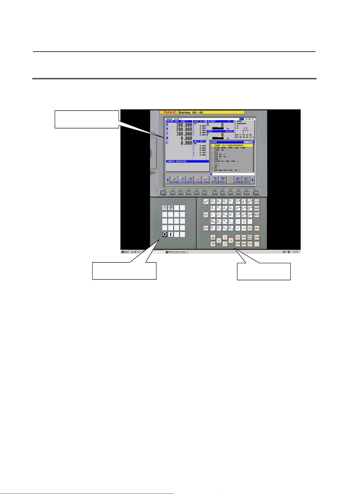
6.MANUAL GUIDE i SIMULATOR FOR THE PERSONAL COMPUTER GENERAL B-63874EN/05
6.4 FULL-SCREEN DISPLAY
When the MANUAL GUIDE i simulator is started, the simulator is
displayed on the full screen of the personal computer.
Main simulator screen
Machine operation
With the MANUAL GUIDE i simulator, the main simulator screen,
the MDI button screen operable using the mouse, and the machine
operation button screen are displayed. A soft key operation can be
performed by clicking a soft key on the main simulator screen or by
pressing a key from F1 to F12 on the keyboard of the personal
computer. Numeric values and uppercase letters can be entered
through the MDI buttons or the keyboard of the personal computer.
For CNC-specific key input, click MDI buttons or machine operation
buttons with the mouse. To quit the simulator, click the machine
operation button [{].
MDI button
- 22 -
Page 45

B-63874EN/05 GENERAL 6.MANUAL GUIDE i SIMULATOR FOR THE PERSONAL COMPUTER
6.5 PARAMETER
1 Parameters created with the FS16i/18i/21i cannot be input.
2 When using a parameter of the FS16i/18i/21i, convert the
parameter to the FS30i format.
3 Parameters in the FS30i format can be used without
modification.
4 The parameters related to the MANUAL GUIDE i function are
basically compatible.
5 Parameter data cannot be output.
6 For the method of parameter input, refer to
"Standard_param¥Readme_j.txt" stored on the CR-ROM.
7 The standard parameters are stored on the CD-ROM. By
editing the file with the text editor and reading the edited file, the
simulator can be customized.
6.6 RESTRICTIONS ON USE
1 Simulation using full-screen display
The MANUAL GUIDE i simulator is executed using the full
screen of the personal computer.
2 Memory card input/output function
A) For input to/output from the memory card, use the memcard
folder under the installation folder. The following can be
input/output using the memory card input/output function:
- NC programs
- Parameters
- Tool database
B) The file name of the file in the memcard folder should
include the extension and be 12 characters or less.
- 23 -
Page 46

6.MANUAL GUIDE i SIMULATOR FOR THE PERSONAL COMPUTER GENERAL B-63874EN/05
6.7 NOTES
1 The operation and functions listed below described in the
operator's manual cannot be used with the MANUAL GUIDE i
simulator for the personal computer.
- Operation in the MDI mode
- Operation in a manual mode (handle, jog)
- Multi-path lathe function
- Tool management function
- Setup support function
2 The MANUAL GUIDE i simulator for the personal computer has
a functional compatibility with the FS30i, but has some
specification restrictions with the FS16i/18i/21i.
3 Those functions that input external signals cannot be used.
4 This does not correspond to the hyper threading technology
function.
- 24 -
Page 47

B-63874EN/05 GENERAL 6.MANUAL GUIDE i SIMULATOR FOR THE PERSONAL COMPUTER
6.8 SIMULATOR DEFINITION FILE FORMAT
The simulator definition file is a text file where information such as
CNC model and display unit size information is written in a specified
format. The ini file format of Windows is used.
6.8.1 Comment
A comment can be written only in a continuous area at the top of a
file.
A comment must start with a single quotation mark (').
A single quotation mark (') written at the start of a halfway data line
does not comment out the character string that follows.
6.8.2 Section
The following two sections are used:
Simulator_MachineSetting_MaxNumber
Simulator_MachineSettingn
(The character n represents a number from 0 to maxnumber of
Simulator_MachineSetting_MaxNumber.)
The character n in the "Simulator_MachineSettingn" section need not
be successive, but must not be duplicate. If n is duplicate, the setting
closer to the top of the file is selected. If a suffix greater than the
maxnumber key is assigned to a setting, the setting is not processed.
6.8.3 Key
The following keys are used:
maxnumber
name
cnctype
displaytype
pathtype
cnctype_title
from_dat_filepath
fileall_dat_filepath
srammgi_dat_filepath
mgidef_folderpath
mgidef_machine_type
userdef_filepath1
userdef_filepath2
keyini_filepath
virtual_memcard_folderpath
- 25 -
Page 48

6.MANUAL GUIDE i SIMULATOR FOR THE PERSONAL COMPUTER GENERAL B-63874EN/05
6.8.3.1 [Simulator_MachineSetting_MaxNumber] section
Key name : maxnumber
Outline : Code a maximum subscript value for the simulator
definitions to be found in the file.
Character string to be set : Maximum subscript number to be found
Explanation : Code a maximum subscript value for the simulator
definitions in the simulator definition file. A search
for a simulator definition is made until n of the
Simulator_MachineSettingn section reaches
maxnumber. A found simulator definition is displayed
in a selection dialog box.
6.8.3.2 [Simulator_MachineSettingn] section
Key name : name
Outline : Code the name assigned to a simulator definition.
Character string to be set : Arbitrary
Explanation : Code the name assigned to a simulator definition. The
character string coded here is displayed in the simulator
definition selection dialog box displayed when the MGi
manager is started.
Key name : cnctype
Outline : Code a CNC model.
Character string to be set : "FS16i", "FS18i", "FS21i", "FS30i"
Explanation : Code the model of the CNC. If an attempt to read a
file described below such as a From.dat file fails, the
model coded in the MGi manager ini file is used.
Key name : displaytype
Outline : Code a display unit type.
Character string to be set : "10.4", "15"
Explanation : Code the type of the display unit. At present, specify
"10.4" or "15".
Key name : pathtype
Outline : Code a path type.
Character string to be set : "T", "TT", "TTT", "M", "TM", etc.
Explanation : Code a path type. Specify "T" for T series single-path
control. Specify "TT" for T series two-path control.
Specify "M" for the M series. Specify "TM" for
compound control.
Key name : cnctype_title
Outline : Set a CNC model name for display.
Character string to be set : Arbitrary
Explanation : Set a CNC model name for display.
- 26 -
Page 49

B-63874EN/05 GENERAL 6.MANUAL GUIDE i SIMULATOR FOR THE PERSONAL COMPUTER
Key name : from_dat_filepath
Outline : Code the relative path of From.dat corresponding to a
selected simulator definition.
Character string to be set : Relative path of From.dat
Explanation : Specify the relative path of From.dat corresponding to a
selected simulator definition. The file coded here is
copied under the name "From.dat" to the memcard
directory under the simulator execution directory.
Key name : fileall_dat_filepath
Outline : Code the Relative path of file_all.dat corresponding to a
selected simulator definition.
Character string to be set : Relative path of file_all.dat
Explanation : Specify the relative path of file_all.dat corresponding to
a selected simulator definition. The file coded here is
copied under the name "file_all.dat" to the simulator
execution directory.
Key name : srammgi_dat_filepath
Outline : Code the relative path of sram_mgi.dat corresponding
to a selected simulator definition.
Character string to be set : Relative path of sram_mgi.dat
Explanation : Specify the relative path of sram_mgi.dat corresponding
to a selected simulator definition. The file coded here
is copied under the name "sram_mgi.dat" to the
simulator execution directory.
Key name : mgidef_folderpath
Outline : Code the relative path of the folder storing the
MANUAL GUIDE definition file of a selected
simulator definition.
Character string to be set :
Relative path of the folder storing a MANUAL GUIDE
definition file (ending with "¥").
Explanation : Code the relative path of the folder storing the
MANUAL GUIDE definition file of a selected
simulator definition. From the folder coded here, a
MANUAL GUIDE definition file matching the type of
the definition file to be specified next is copied together
with the language file to the simulator execution
directory.
Key name : mgidef_machine_type
Outline : Code the type of a MANUAL GUIDE definition file.
Character string to be set :
"TURN_VERTICAL", "TURN_HORIZONTAL",
"MILLING_VERTICAL",
"MILLING_HORIZONTAL"
Explanation : Code the type (T/M series, vertical/horizontal) of a
MANUAL GUIDE definition file. The file coded here
is copied to the simulator execution directory.
- 27 -
Page 50

6.MANUAL GUIDE i SIMULATOR FOR THE PERSONAL COMPUTER GENERAL B-63874EN/05
Key name : userdef_folderpath1
Outline : Code the relative path of the user definition file of a
selected simulator definition.
Character string to be set : Relative path of a user definition file
Explanation : Code the relative path of the user definition file of a
selected simulator definition. The file coded here is
copied under the name "cex2datu" to the simulator
execution directory. Up to two user definition files
can be specified. If no user definition file is necessary,
specify a null character string.
Key name : userdef_folderpath2
Outline : Code the relative path of the user definition file of a
selected simulator definition.
Character string to be set : Relative path of a user definition file
Explanation : Code the relative path of the user definition file of a
selected simulator definition. The file coded here is
copied under the name "cex3datu" to the simulator
execution directory. Up to two user definition files
can be specified. If no user definition file is necessary,
specify a null character string.
Key name : keyini_filepath
Outline : Code the relative path of an MDI key setting file.
Character string to be set : Relative path of an MDI key setting file
Explanation : Code the relative path of a setting file specifying the
layout of MDI keys, and so forth. By using
information such as character strings for input key
determination and button display positions stored in the
file specified here, the MGi manager displays the MDI
keys on the MGi manager.
- 28 -
Page 51

B-63874EN/05 GENERAL 6.MANUAL GUIDE i SIMULATOR FOR THE PERSONAL COMPUTER
6.9 DISPLAY DATA ini FILE FORMAT
The display data ini file is a text file where information about images
and buttons to be arranged on the screen is specified. The ini file
format of Windows is used.
6.9.1 Comment
A comment can be written only in a continuous area at the top of a
file.
A comment must start with a single quotation mark (').
A single quotation mark (') written at the start of a halfway data line
does not comment out the character string that follows.
6.9.2 Section
The following sections are used:
[settings]
[frame_mainscreen]
[cnctitle]
[softkey]
[frame_mdikey]
[mdikey]
[frame_functionkey]
[functionkey]
[settings] : Specifies general screen layout information.
[frame_mainscreen] : Specifies information such as screen component
positions on the CNC display section.
[cnctitle] and [softkey] below are included in
this frame.
[cnctitle] : Setting for CNC model title section display
[softkey] : Setting for soft key display
[frame_mdikey] : Frame display setting for MDI key display
[mdikey] : Setting for MDI key display
[frame_functionkey] : Setting for display of keys such as the mode
switch key other than the MDI keys
[functionkey] : Setting for display of keys such as the mode
switch key
- 29 -
Page 52

6.MANUAL GUIDE i SIMULATOR FOR THE PERSONAL COMPUTER GENERAL B-63874EN/05
6.9.3 Key
The keys are described on a section-by-section basis.
6.9.3.1 [settings] section
Key name : bgcolor
Outline : Specify a background color.
Setting method : bgcolor = r, g, b
Specify a number from 0 to 255 in r, g, and b.
Example: Grey is specified as the background color.
bgcolor = 128,128,128
Details : Specify a background color by the lightness values
of red (r), green (g), and blue (b). A lightness
value ranges from 0 to 255. If a value greater than
255 is specified, the specification of 255 is assumed.
The background color specified here is used as the
background color for the overall screens and frames.
Key name : cncscrn_offsetx, cncscrn_offsety
Outline : Specify the display position of a CNC display
section application.
Setting method : cncscrn_offsetx = x
: cncscrn_offsety = y
Each of x and y represents the number of pixels from
the top-left corner of the screen.
Example: CNCScrn.exe is displayed at (320,60)
from the top-left corner of the screen.
cncscrn_offsetx=320
cncscrn_offsety=60
Details : Specify the position of a CNC display section
application in pixels. Specify (x,y) in pixels, with
(x,y) = (0,0) for the top-left corner of the screen.
When an NC frame image is displayed, for example,
specify (x,y) to display the CNC display section at a
proper position.
Key name : layout
Outline : Code the layout of MDI keys.
Setting method : layout = QWERTY | ONG-M | ONG-T | MINI-M |
MINI-T
Example: The QWERTY layout is selected for the
MDI keys.
layout=QWERTY
Details : Set the layout of MDI keys by using a specified
character string. Here, only a layout name is
specified. The actual layout of keys is not
determined here.
- 30 -
Page 53

B-63874EN/05 GENERAL 6.MANUAL GUIDE i SIMULATOR FOR THE PERSONAL COMPUTER
6.9.3.2 [frame_mainscreen] section
Key name : image
Outline : Specify the path of an image to be displayed in the
CNC display section area of the MGi manager.
…
Setting method : image = drive:¥dir1
Example: image=.¥image¥frameFS30i.bmp
Details : Specify the path of a frame image to be displayed
around the CNC display section. When no fame is
to be displayed, delete the coding of the key itself.
Either an absolute path or a relative path may be
used. The usable types of image files are bmp, jpg,
and gif. The size of an image must match the size
of the frame. Those portions that exceed the frame
are not displayed. Those portions that do not reach
the frame size are filled using the color specified by
bgcolor.
Key name : visible
Outline : Specify whether to display the main frame.
Setting method : visible = 0 | 1
Example: When the main frame is displayed
visible=1
Details : Specify whether to display the main frame. When
0 is specified, the main frame is not displayed.
When 1 is specified, the main frame is displayed.
The main frame includes the NC title and soft keys.
So, when 0 is specified not to display the main frame,
the CNC display section is displayed, but the title
and soft keys are not displayed.
Key name : left, top, width, height
Outline : Specify the display position and size of the main
frame.
Setting method : left = left
top = top
width = width
height = height
Example: When the position of the main frame is
(230,20), and the size of the main frame
is (800,600)
left=230
top=20
width=800
height=600
Details : Specify the position and size of the main frame in
pixels. For display position specification, assume
that the top-left corner of the screen is at (left,top) =
(0,0). When an image is to be pasted, the size must
match the size of the image.
¥filename
- 31 -
Page 54

6.MANUAL GUIDE i SIMULATOR FOR THE PERSONAL COMPUTER GENERAL B-63874EN/05
6.9.3.3 [cnctitle] section
Key name : image
Outline : Specify the path of a title image to be displayed
within the main frame.
…
Setting method : image = drive:¥dir1
Example: image=.¥image¥titleFS30i.bmp
Details : Specify the path of the file storing a title image to be
displayed. Either an absolute path or a relative
path may be used. When the image key itself is
deleted, no image is displayed, but the character
string of the title specified in the simulator definition
is displayed as text. The usable types of image
files are bmp, jpg, and gif. The size of an image
must match the size of the frame. Those portions
that exceed the frame are not displayed. Those
portions that do not reach the frame size are filled
using the color specified by bgcolor.
Key name : visible
Outline : Specify whether to display the title section.
Setting method : visible = 0 | 1
Example: When the title section is displayed
visible=1
Details : Specify whether to display the title. When 0 is
specified, the title is not displayed. When 1 is
specified, the title is displayed. Specify 0, for
example, when an image pasted to the main frame
already includes a title, and no title needs to be
drawn additionally.
Key name : left, top, width, height
Outline : Specify the display position and size of the title
section.
Setting method : left = left
top = top
width = width
height = height
Example: When the display position of the title
section is (540,180), and the size of the
title section is (7000,400)
left=540
top=180
width=7000
height=400
Details : Specify the display position and size of the title
section in twip. Specify a desired display position
as relative coordinates on the main frame, with
(left,top) = (0,0) for the top-left corner of the main
frame. When an image is to be pasted, the size
must match the size of the image.
¥filename
- 32 -
Page 55

B-63874EN/05 GENERAL 6.MANUAL GUIDE i SIMULATOR FOR THE PERSONAL COMPUTER
6.9.3.4 [softkey] section
Key name : keynum
Outline : Specify the number of buttons that are displayed in
the main frame and operate as soft keys.
Setting method : keynum = n
Example: When 12 soft keys are used
keynum=12
Details : Specify the number of buttons that are displayed in
the main frame and used as function keys. The
number of buttons specified here is used to specify
the number of key pressing information items to be
read next.
Key name : keyn (n: 0 to keynum-1)
Outline : Code a setting to be assigned to a button used as a
key.
Setting method : keyn = key1, key2, x, y, imagefile
Example: When the first soft key is assigned to the
operation of the F1 key, the display
position is (900,8220), and an image to
be pasted is specified
key0={F1},{F1},900,8220,.¥image¥skey_l.bmp
Details : Code information for setting of a button to be
assigned as a soft key. The following information
is to be set:
key1 Specify key information (to be described
later) to be passed to the CNC display
section application when a button is
pressed.
key2 Specify key information to be passed to
the CNC display section application
when a button is pressed while the
SHIFT button is held down.
x, y Specify the display position of a button
in twip. For display position setting,
specify relative coordinates on the main
frame, with (x,y) = (0,0) for the top-left
corner of the main frame.
Imagefile Specify the path of the image file to be
pasted to a button. The size of an image
for a soft key is 28×28 pixels when the
CNC model specified in the simulator
definition is FS30i, and is 33×18 pixels
for other cases.
- 33 -
Page 56

6.MANUAL GUIDE i SIMULATOR FOR THE PERSONAL COMPUTER GENERAL B-63874EN/05
6.9.3.5 [frame_mdikey] section
Key name : image
Outline : Specify the path of an image to be displayed as a
frame for MDI key display.
…
Setting method : image = drive:¥dir1
Example: image=.¥image¥frameQWERTY.bmp
Details : Specify the path of a frame image to be displayed
around the MDI keys. When no frame is to be
displayed, delete the coding of the key itself.
Either an absolute path or a relative path may be
used. The usable types of image files are bmp, jpg,
and gif. The size of an image must match the size
of the frame. Those portions that exceed the frame
are not displayed. Those portions that do not reach
the frame size are filled using the color specified by
bgcolor.
Key name : visible
Outline : Specify whether to display a frame for MDI key
display.
Setting method : visible = 0 | 1
Example: When a frame for MDI key display is
displayed
visible=1
Details : Specify whether to display a frame for MDI key
display. When 0 is specified, no frame for MDI
display is displayed. When 1 is specified, a frame
for MDI key display is displayed. When 0 is
specified, the MDI keys are not displayed.
Key name : left, top, width, height
Outline : Specify the display position and size of a frame for
MDI key display.
Setting method : left = left
top = top
width = width
height = height
Example: When the display position of a frame for
MDI key display is (230,20), and the size
is (800,600)
left=230
top=20
width=800
height=600
Details : Specify the display position and size of a frame for
MDI key display in pixels. For display position
specification, assume that the top-left corner of the
screen is at (left,top) = (0,0). When an image is to
be pasted, the size must match the size of the image.
¥filename
- 34 -
Page 57

B-63874EN/05 GENERAL 6.MANUAL GUIDE i SIMULATOR FOR THE PERSONAL COMPUTER
6.9.3.6 [mdikey] section
Key name : keynum
Outline : Specify the number of buttons that are displayed in a
frame for MDI key display and operate as MDI
keys.
Setting method : keynum = n
Example: When 66 MDI keys are used
keynum=66
Details : Specify the number of buttons that are displayed in a
frame for MDI key display and operate as MDI keys.
The number of buttons specified here is used to
specify the number of key pressing information
items to be read next.
Key name : keyn (n: 0 to keynum-1)
Outline : Code a setting to be assigned to a button used as a
key.
Setting method : keyn = key1, key2, x , y, imagefile
Example: When the first MDI key is assigned to the
operation of "O", the display position is
(6020,1350), and an image to be pasted is
specified
key0=O,{(),6020,1350,.¥image¥o.bmp
Details : Code information for setting of a button to be
assigned as an MDI key. The following
information is to be set:
key1 Specify key information (to be described
later) to be passed to the CNC display
section application when a button is
pressed.
key2 Specify key information to be passed to
the CNC display section application
when a button is pressed while the
SHIFT button is held down.
x, y Specify the display position of a button
in twip. For display position setting,
specify relative coordinates on the frame
for MDI key display, with (x,y) = (0,0)
for the top-left corner of the frame for
MDI key display.
Imagefile Specify the path of the image file to be
pasted to a button. The size of an image
for a soft key is 36×36 pixels.
- 35 -
Page 58

6.MANUAL GUIDE i SIMULATOR FOR THE PERSONAL COMPUTER GENERAL B-63874EN/05
6.9.3.7 [frame_functionkey] section
Key name : image
Outline : Specify the path of an image to be displayed as a
frame for function key display.
…
Setting method : image = drive:¥dir1
Example: image=.¥image¥frameFunc.bmp
Details : Specify the path of a frame image to be displayed
around the function keys. When no frame is to be
displayed, delete the coding of the key itself.
Either an absolute path or a relative path may be
used. The usable types of image files are bmp, jpg,
and gif. The size of an image must match the size
of the frame. Those portions that exceed the frame
are not displayed. Those portions that do not reach
the frame size are filled using the color specified by
bgcolor.
Key name : visible
Outline : Specify whether to display a frame for function key
display.
Setting method : visible = 0 | 1
Example: When a frame for function key display is
displayed
visible=1
Details : Specify whether to display a frame for function key
display. When 0 is specified, no frame for function
display is displayed. When 1 is specified, a frame
for function key display is displayed. When 0 is
specified, the function keys are not displayed.
Key name : left, top, width, height
Outline : Specify the display position and size of a frame for
function key display.
Setting method : left = left
top = top
width = width
height = height
Example: When the display position of a frame for
function key display is (230,20), and the
size is (800,600)
left=230
top=20
width=800
height=600
Details : Specify the display position and size of a frame for
function key display in pixels. For display position
specification, assume that the top-left corner of the
screen is at (left,top) = (0,0). When an image is to
be pasted, the size must match the size of the image.
¥filename
- 36 -
Page 59

B-63874EN/05 GENERAL 6.MANUAL GUIDE i SIMULATOR FOR THE PERSONAL COMPUTER
6.9.3.8 [functionkey] section
Key name : keynum
Outline : Specify the number of buttons that are displayed in a
frame for function key display and operate as
function keys.
Setting method : keynum = n
Example: When two function keys are used
keynum=2
Details : Specify the number of buttons that are displayed in a
frame for function key display and operate as
function keys. The number of buttons specified
here is used to specify the number of key pressing
information items to be read next.
Key name : keyn (n: 0 to keynum-1)
Outline : Code a setting to be assigned to a button used as a
key.
Setting method : keyn = key1, key2, x , y, imagefile
Example: When the first function key is assigned to
the operation of the "auto" key, the
display position is (450,660), and an
image to be pasted is specified
key0=^r,^r,450,60,.¥image¥auto.bmp
Details : Code information for setting of a button to be
assigned as a function key. The following
information is to be set:
key1 Specify key information (to be described
later) to be passed to the CNC display
section application when a button is
pressed.
key2 Specify key information to be passed to
the CNC display section application
when a button is pressed while the
SHIFT button is held down.
x, y Specify the display position of a button
in twip. For display position setting,
specify relative coordinates on the frame
for function key display, with (x,y) =
(0,0) for the top-left corner of the frame
for function key display.
Imagefile Specify the path of the image file to be
pasted to a button. The size of an image
for a soft key is 36×36 pixels.
- 37 -
Page 60

6.MANUAL GUIDE i SIMULATOR FOR THE PERSONAL COMPUTER GENERAL B-63874EN/05
6.9.3.9 Information to be passed when a button is pressed
When specifying buttons such as soft keys, MDI keys, and function
keys in a display data ini file, specify key information to be passed to
the CNC display section application when the buttons are pressed .
The format for key specification is described below.
The format for button setting is as follows:
Setting method : keyn = key1, key2, x , y, imagefile
To assign the pressing of "a" when the keyn button is pressed, code
"a" in key1. To input "b" when the key is pressed while the SHIFT
key is held down, code "b" in key2.
Example: keyn = a, b, x , y, imagefile
* A character coded here is input to the CNC display section
application. So, if a character not supported by the CNC
display section application is coded, an unpredictable operation
results.
The table below indicates the CNC keys and corresponding
character strings. In an ini file, code the character strings
corresponding to CNC keys to be operated.
- 38 -
Page 61

B-63874EN/05 GENERAL 6.MANUAL GUIDE i SIMULATOR FOR THE PERSONAL COMPUTER
CNC key Corresponding
character string
A a 1 1
B b 2 2
C c 3 3
D d 4 4
E e 5 5
F f 6 6
G g 7 7
H h 8 8
I i 9 9
J j 0 0
K k L l
M m / /
N n ( {(}
O o ) {)}
P p ? ?
Q q , COMMA
R r @ (No corresponding
S s # #
T t = =
U u * *
V v + {+}
W w [ [
X x ] ]
Y y & (No corresponding
Z z SP SPACE
CNC key Corresponding
character string
-
. .
character string)
character string)
- 39 -
Page 62

6.MANUAL GUIDE i SIMULATOR FOR THE PERSONAL COMPUTER GENERAL B-63874EN/05
CNC key Corresponding
character string
RESET @ SOFTKEY 1 Q
HELP {‘} SOFTKEY 2 A
SHIFT SHIFT SOFTKEY 3 Z
ALTER ` SOFTKEY 4 X
INSERT ^n SOFTKEY 5 C
DELETE DEL SOFTKEY 6 V
INPUT {ENTER} SOFTKEY 7 B
PAGEUP PDUP SOFTKEY 8 N
PAGEDOWN PGDN SOFTKEY 9 M
UP E SOFTKEY 10 L
DOWN D SOFTKEY 11 R
LEFT S SOFTKEY 12 T
RIGHT F SOFTKEY 13 Y
MEM MODE ^r SOFTKEY 14 U
EDIT MODE ^d SOFTKEY 15 I
EXIT %{F4} SOFTKEY 16 O
SOFTKEY L W SOFTKEY 17 G
SOFTKEY R P SOFTKEY 18 H
SOFTKEY 19 ¥
CNC key Corresponding
character string
- 40 -
Page 63

II. OPERATION
Page 64

Page 65

B-63874EN/05 OPERATION 1.OVERVIEW OF THE PROCEDURE
1 OVERVIEW OF THE PROCEDURE
- 43 -
Page 66

1.OVERVIEW OF THE PROCEDURE OPERATION B-63874EN/05
1.1 MAIN FEATURES OF MANUAL GUIDE i
By using MANUAL GUIDE i, the operator can carry out routine
machining easily.
1) Integrated operation screen that enables almost all routine
machining operations
A single integrated operation screen enables routine machining
operations including machining program input/editing, animated
simulation-based machining program checks, production
machining, MDI operations, and manual operations with JOG
and HANDLE.
2) Machining programs in ISO code format
Using ISO code machining programs, which are in wide use,
enables the operator to specify simple operations with simple
commands, such as those for straight lines and arcs, and
complicated machining operations with machining cycles easily.
3) High affinity with CAD/CAM
ISO code machining programs created using CAD/CAM can be
used without modification. Adding advanced machining cycles to
these machining programs makes them perfect machining
programs. They can be checked easily, using animated
simulation.
4) Advanced machining program editing
Using advanced editing functions, such as substring search and
cut/paste via the clipboard, enables easy editing of machining
programs.
5) Advanced machining using machining cycles (option)
Advanced machining cycles are available which cover various
types of machining including milling and turning. With these
machining cycles, it is possible to perform complex machining
by creating and running programs easily.
6) Fixed format program menu-driven simple program entry
Register a series of frequently used machining operations
previously as a menu, and select necessary machining operations
from the menu when creating a machining program. This method
can eliminate the trouble of entering similar machining
operations repeatedly.
7) M code menu
It is possible to input M codes easily by referencing explanations
displayed in an M code menu. Machine tool builders can create
the explanations easily.
- 44 -
Page 67

B-63874EN/05 OPERATION 1.OVERVIEW OF THE PROCEDURE
8) Realistic animated simulation (option)
Machining programs can be checked easily, using an animated
simulation method that can realistically show what the surface
machined with a specific type of tool tip is like. In addition, you
can check a simulated workpiece as if you were looking at a real
workpiece because the animated simulation method uses solid
models for all operations, from milling to turning, for the
workpiece.
9) Advanced set-up guidance (option)
It is possible to set up machining operations and check the
precision of machined workpieces easily, using an advanced
set-up guidance function that can handle all measurements, from
tool offset measurement to the measurement of workpieces in
machine tools.
10) Supporting a wide variety of machine types including lathes
and machining centers
MANUAL GUIDE i supports lathes 1 to 3, vertical and
horizontal machining centers, and tilting head-equipped
machining centers with 3 + 2 axes. It also supports compound
machine tools that are capable of turning and milling.
- 45 -
Page 68

2.MACHINING PROGRAM FORMAT OPERATION B-63874EN/05
2 MACHINING PROGRAM FORMAT
Machining programs used with MANUAL GUIDE i are created using
the ISO code format, which is widely used in CNC machine tools.
They use 4-digit G code machining and measurement cycles to
implement further advanced machining operations.
These 4-digit G code machining and measurement cycles can be input
and edited easily, using menu windows in which machining data can
be entered interactively.
When a machining program is being edited, an explanation about an
address pointed to with the cursor is displayed at the bottom of the
screen.
Remark)
“Word” is the minimum data unit of NC part program, and
specified by the combination of address (A to Z) and numerical
data (0 to 9, +, -, decimal point).
“Address” means the content of numerical data such as moving
axis name.
Remark)
“Cursor” of the part program means the part whose background
area is displayed by yellow. The part displayed by yellow is
called “selected by the cursor”, and program editing operation
will be dealt on this part.
There are 2 case cases for the selected part by the cursor.
(1) 1 block
When the cursor moved the top of the next block by
pressing the cursor key →, the whole word data included in
the block are selected.
When the cursor selects the top word data of some block,
the whole word data included in the block are selected by
pressing the cursor key ←.
In case that the whole word data include in the block are
selected by the cursor, the next or previous 1 block will be
selected by pressing the cursor key ↓ or ↑.
(2) 1 word
In case that the whole word data in 1 block are selected by
the cursor as described above, if you push the cursor key ←
or →, the cursor will select 1 word only. By pressing the
cursor key ← or → again, the cursor will select the next 1
word.
When the 1 word is selected, the cursor will select the 1
word of same order in the nest or previous block by
pressing the cursor key ↑ or ↓.
- 46 -
Page 69

B-63874EN/05 OPERATION 2.MACHINING PROGRAM FORMAT
Remark)
In the screen, in which numerical data are directly entered such
as offset data or cycle machining data, the cursor is specified by
displaying the data frame by blue.
The part specified by blue frame is called “data item selected by
the cursor”, and you can enter the proper data by pressing
INPUT key after entering numeric data by numeric keys.
By pressing the cursor key ← ↑ → ↓, you can select the next or
previous data item.
- 47 -
Page 70

3.EDITING MACHINING PROGRAMS OPERATION B-63874EN/05
3 EDITING MACHINING PROGRAMS
- 48 -
Page 71

B-63874EN/05 OPERATION 3.EDITING MACHINING PROGRAMS
3.1 MACHINING PROGRAM WINDOW AND EIDITNG
MANUAL GUIDE i uses a program window to input and edit
machining programs (in ISO code format).
The program window is operated using the following soft keys, which
are displayed by pressing the leftmost soft key [<] or rightmost soft
key [>] several times.
REWIND
CHSIZE
LINENO
[REWIND] : This soft key takes you to the beginning of the program.
[CHSIZE] : This soft key zooms the program window to full screen.
[LINENO] : This soft key selects whether to display the line number
at the beginning of each block. The line number is not
memorized in the machining program.
[SETING] : This soft key opens the setting screen.
The scroll bar displayed on the right edge of the program window
indicates the approximate position of the cursor throughout the
machining program.
The cursor is moved around in the program window, using the cursor
keys ←, ↑, ↓, and →. Pressing → moves the cursor right in a block.
To move the cursor to the next block, you need to select the block
entirely once and then select an individual address. Pressing. ← has
the same effect as for → except for the direction in which the cursor
moves.
SETING
- 49 -
Page 72

3.EDITING MACHINING PROGRAMS OPERATION B-63874EN/05
The program is edited using the following soft keys, which are
displayed by pressing the leftmost soft key [<] or rightmost soft key
[>] several times.
NEWPRG
OPEN
SRCH↑ SRCH↓
Remark)
Basically, soft keys are placed in form of 1 line. By pressing the
When the right end soft keys are displayed, the left end soft keys
O SRCH
COPY
CUT
DELETE
KEYPST
right end key [>], the soft keys shifted to right direction by 10
will appear. By pressing the left end key [<], the left side soft
keys shifted by 10 will appear.
will appear by pressing [>]. When the left end soft keys are
displayed, the right end soft keys will appear by pressing [<].
PASTE
- 50 -
Page 73

B-63874EN/05 OPERATION 3.EDITING MACHINING PROGRAMS
3.2 CREATING MACHINING PROGRAMS
NEWPRG
O LIST
SRCH↑ SRCH↓
Pressing [NEWPRG] displays the program creation window.
O SRCH
COPY
CUT
DELETE
KEYPST
PASTE
NEWPRG
O LIST
For the program creation window, the following soft keys are
displayed.
In this window, enter a program number, using numeric keys, and then
press [CREATE].
Usually, the program number is 4 digits, but you can use 8 digits
program number when the corresponding optional function is added.
Pressing [CREATE], new program with entered program number only
is created, and it is displayed in the program window. In that case, the
following soft keys for editing operation are displayed.
SRCH↑ SRCH↓
In addition to the above operation, you can create new part program
by entering new program number after the address “O”, and pressing
INSERT key.
O SRCH
COPY
CUT
DELETE
CREATE
KEYPST
CANCEL
PASTE
- 51 -
Page 74

3.EDITING MACHINING PROGRAMS OPERATION B-63874EN/05
3.3 EDITING IN A PROGRAM LIST
NEWPRG
O LIST
SRCH↑ SRCH↓
Pressing [O LIST] displays a window that lists registered machining
programs.
By pressing the ← or → cursor key, a sort type (sort by number, sort
by date and time of updating, or sort by size) can be selected.
O SRCH
COPY
CUT
DELETE
KEYPST
PASTE
NEW
COPY
The following soft keys are displayed in the window. They can be
used for editing such as copying or deleting machining programs.
DELETE EDTCOM
[NEW] : This soft key displays the program creation window, in
[COPY] : This soft key displays the program copy window. After
[DELETE] : This soft key displays a message for asking you
[EDTCOM] : This soft key displays the comment (program name)
SEARCH
M CARD
ALLDEL
SRTORD
OPEN
CLOSE
which you can create machining programs.
a program number is entered using numeric keys,
pressing [COPY] copies the specified program.
whether you really want to delete a specified program.
Pressing [YES] deletes the specified program. Pressing
[NO] cancels the request to delete the specified
program.
edit window. If you move the cursor, using ← or →,
and enter a character, using MDI keys, the character
appears at the left of the cursor. Using the CAN key can
delete the character at the left. Pressing [ALTER]
causes the comment to be changed.
- 52 -
Page 75

B-63874EN/05 OPERATION 3.EDITING MACHINING PROGRAMS
[SEARCH] : This soft key displays the program search window.
After entering a desired program number in the window,
using numeric keys, press [SEARCH].
[M CARD] : This soft key enables input/output to and from the
memory card.
[ALLDEL] : This soft key displays a message for checking if all
programs may be deleted. Pressing [YES] deletes all
programs. Pressing [NO] cancels the deletion of all
programs.
[SRTORD] : This soft key switches the sort order for displaying
programs between ascending order and descending
order.
[OPEN] : After placing the cursor on a program you want to edit,
using the ↑ or ↓ cursor key, pressing this soft key
selects the program and closes the list window. Then,
the soft keys described at the top of this subchapter are
displayed again.
[CLOSE] : This soft key closes the program list window.
- 53 -
Page 76

3.EDITING MACHINING PROGRAMS OPERATION B-63874EN/05
3.4 SEARCHING FOR A MACHINING PROGRAM TO BE
EDITED
NEWPRG
O LIST
SRCH↑ SRCH↓
After entering a desired program number, using numeric keys,
pressing [O SRCH] can select the program.
Pressing [O SRCH] without entering a program number causes the
next program to be selected.
Pressing the O key on the MDI panel, the soft keys changes to the
above one, so enter the program number to be searched and press [O
SRCH].
And as another way, you can select the program in the program list by
pressing [OPEN] after placing the cursor on the program number to be
selected.
When the part program is selected, the content of the part program is
displayed in the program window, and the above soft keys will be
displayed.
O SRCH
COPY
CUT
DELETE
KEYPST
PASTE
- 54 -
Page 77

B-63874EN/05 OPERATION 3.EDITING MACHINING PROGRAMS
3.5 BASIC EDITING OPERATIONS OF PART PROGRAM
Since MANUAL GUIDE i uses ISO-code form part program, editing
of 1 word, minimum unit of the program and made from address and
numerical data, are available by using INSERT, ALTER and
DELETE keys, which are placed on the MDI panel.
3.5.1 Entering a Word (INSERT key)
Operation
(1) Select the word, before which you want to insert the new
word, by placing the cursor. Otherwise, select the block,
before which you want to insert the new word, by placing
the cursor.
(2) Enter new word by MDI keys. Plural words can be entered
at once.
(3) Press INSERT.
NOTE
1 In the case a parameter No.14852#2(G4E) is set to
0, when a cursor is placed on the word in the cycle
machining block and an operator is going to insert a
new word, the warning to confirm an operator
whether it can be done or not will be displayed.
3.5.2 Modifying a Word (ALTER key)
Operation
(1) Select the word to be modified by placing the cursor on the
word.
(2) Enter new word by MDI keys. Plural words can be entered
at once.
(3) Press ALTER.
3.5.3 Modifying the Numeric Value of a Word (ALTER key)
Operation
(1) Select the word to be modified by placing the cursor on the
word.
(2) Enter new numeric data only by MDI keys. Plural words
can not be entered.
(3) Press ALTER.
- 55 -
Page 78

3.EDITING MACHINING PROGRAMS OPERATION B-63874EN/05
3.5.4 Deleting a Word (DELETE key)
Operation
(1) Select the word to be deleted by placing the cursor on the
word.
(2) Press DELETE.
NOTE
1 As the deleting operation in the CNC program
screen, no prompting message for deleting a word
is displayed.
2 Program number, Oxxxx, and end of program, %,
cannot be deleted.
3.5.5 Modifying a Block (ALTER key)
Operation
(1) Select the block to be modified by placing the cursor on the
block.
(2) Enter new word by MDI keys. Plural words can be entered
at once.
(3) Press ALTER.
3.5.6 Deleting a Block (DELETE key)
Operation
(1) Select the block to be deleted by placing the cursor on the
block.
(2) Press DELETE.
3.5.7 Changing the Program Number (ALTER key)
Operation
(1) Select the program number word, Oxxxx, by placing the
cursor on the word.
(2) Enter the address “O” and new program number by MDI
keys.
(3) Press ALTER.
- 56 -
Page 79

B-63874EN/05 OPERATION 3.EDITING MACHINING PROGRAMS
3.6 SEARCH (FORWARD AND BACKWARD)
NEWPRG
O LIST
SRCH↑ SRCH↓
[ ]
After a character string is entered using MDI keys, pressing [SRCH↑]
(backward search) or [SRCH↓] (forward search) searches for the
specified character string. A substring can also be searched for.
If the character string is found, key-in buffer is cleared, but the string
is displayed in the [ ] under [SRCH↑] and [SRCH↓].
This displayed string can be used for the next time searching operation.
Only pressing [SRCH↑] or [SRCH↓] without entering same string
again, you can search the same string over and over.
O SRCH
COPY
CUT
DELETE
KEYPST
PASTE
- 57 -
Page 80

3.EDITING MACHINING PROGRAMS OPERATION B-63874EN/05
3.7 CUT
NEWPRG
O LIST
SRCH↑ SRCH↓
Pressing [CUT] displays a message that prompts you to select a range
of data to be cut. First select the cut range (by displaying it in yellow),
using cursor keys, and then press [CUT]. The data cut off from the
specified range is stored on the clipboard. The contents of the
clipboard can be pasted to other places in the program and to other
programs.
Clip board is the memory, in which the content of part program can be
stored temporary. By pressing [CUT] or [COPY], the content of the
cursor selected is stored in it, then the old content is cleared. The
content of the clip board is cleared at the power off of CNC.
A clip board size can be selected using bits 4 and 5 of parameter No.
14701.
Bit 4 = 0, bit 5 = 0: Sets a clip board size of 1024 bytes.
Bit 4 = 1, bit 5 = 0: Sets a clip board size of 2048 bytes.
Bit 4 = 0, bit 5 = 1: Sets a clip board size of 4096 bytes.
Bit 4 = 1, bit 5 = 1: Sets a clip board size of 8192 bytes.
O SRCH
COPY
CUT
DELETE
KEYPST
NOTE
The contents of the clipboard are preserved until
the power is shut off or other data is stored on the
clipboard. So, the clipboard contents can be used
any number of times.
PASTE
3.8 COPY
NEWPRG
O LIST
SRCH↑ SRCH↓
O SRCH
COPY
CUT
DELETE
KEYPST
PASTE
Pressing [COPY] displays a message that prompts you to select a
range of data to be copied. First select the copy range (by displaying it
in yellow), using cursor keys, and then press [COPY]. The data copied
from the specified range is stored on the clipboard. The contents of the
clipboard can be pasted to other places in the program and to other
programs.
- 58 -
Page 81

B-63874EN/05 OPERATION 3.EDITING MACHINING PROGRAMS
3.9 PASTE
NEWPRG
O LIST
SRCH↑ SRCH↓
O SRCH
COPY
CUT
DELETE
KEYPST
PASTE
Pressing [PASTE] pastes the contents of the clipboard to the place that
immediately follows the current cursor position.
The clipboard contents are preserved.
3.10 DELETE
NEWPRG
O LIST
SRCH↑ SRCH↓
Pressing [DELETE] displays a message that prompts you to select a
range of data to be deleted. First select the delete range (by displaying
it in yellow), using cursor keys, and then press [SELECT]. A message
appears which asks whether you really want to delete the selected data.
Pressing [YES] deletes the data.
The deleted data is not stored on the clipboard. The clipboard
preserves the previous contents.
O SRCH
COPY
CUT
DELETE
KEYPST
PASTE
- 59 -
Page 82

3.EDITING MACHINING PROGRAMS OPERATION B-63874EN/05
3.11 KEY-IN PASTE
NEWPRG
O LIST
SRCH↑ SRCH↓
Pressing [KEYPST] copies the contents of a range selected (displayed
in yellow) using the cursor to the key-in buffer.
Using the ← and → cursor keys can move the cursor around in the
key-in buffer, so a character entered using an MDI key can be placed
immediately before the cursor. Pressing the CAN key deletes the
character at the left of the cursor.
The character strings in the key-in buffer can be used in the same
manner as for ordinary editing. Pressing the ALTER key, for example,
replaces the cursor-selected current contents in the program with the
current contents of the key-in buffer. Pressing the INSERT key
inserts the key-in buffer contents to the place that immediately follows
the cursor-selected contents in the program.
Pressing CAN after SHIFT clears the contents of the key-in buffer.
O SRCH
COPY
CUT
DELETE
KEYPST
NOTE
Using key-in paste enables a very long comment
program and part of a custom macro program block
to be changed easily.
PASTE
- 60 -
Page 83

B-63874EN/05 OPERATION 3.EDITING MACHINING PROGRAMS
3.12 UNDO, REDO
G-CONT
UNDO
REDO
WK-SET
T-OFS
Pressing [REDO] during editing in the MDI mode, EDIT mode, or
MEM mode can cancel (undo) a program editing operation using the
MANUAL GUIDE i. Pressing [UNDO] can cancel (redo) the
cancellation of an operation. This function can be used, for example,
when a block has been deleted by mistake.
NOTE
1 Before the undo function or redo function can be
used with MANUAL GUIDE i, the size of a buffer
for storing operations must be set in parameter No.
14861. When 0 is set in the parameter, a 5-KB
buffer is allocated.
2 The undo and redo functions can be used for
editing operations in a selected program. This
means that the creation of a new program and the
deletion of a program cannot be undone, and the
editing of the key-in buffer cannot be undone.
3 When the screen display is switched or an
operation for opening a program is performed, the
buffer is cleared.
SETING
- 61 -
Page 84

3.EDITING MACHINING PROGRAMS OPERATION B-63874EN/05
3.13 M-CODE MENU
Pressing the leftmost soft key [<] or rightmost soft key [>] several
times displays [M CODE] as follows:
START
CYCLE
MECYCEND
ALTER
FIGURE
M CODE
Pressing [M CODE] displays the M code menu.
FIXFRM
The following soft keys are displayed for M-code menu.
INSERT
INS+;
CANCEL
Select an M code group, using the ← and → cursor keys, and then
select an M code from the M code group, using the ↑ and ↓ cursor
keys.
Pressing [INSERT] inserts the selected M code to the place that
follows immediately the cursor position in the program. Pressing
[INS+;] inserts an EOB to the place that follows immediately the M
code at the same time.
Entering M-code continuously and pressing [INS+;] at last, plural
M-code can be entered in one block.
By the following operations, M-code in a part program can be altered
directly by using M-code menu.
1) Place a cursor on the M-code should be altered.
2) Press [ALTER] or INPUT-key, then M-code menu will be
displayed.
3) Select a M-code by placing a cursor in the M-code menu
window.
- 62 -
Page 85

B-63874EN/05 OPERATION 3.EDITING MACHINING PROGRAMS
4) Pressing [ALTER], then M-code will be replaced to the newly
selected one.
NOTE
1 In many cases, M codes in the M code menu are
set up to a machine tool by the machine tool
builder. So, the M code menu varies from one
machine tool to another.
2 If the bit 4 of parameter No. 14850 is set to 1, M
code menu is disabled.
- 63 -
Page 86

3.EDITING MACHINING PROGRAMS OPERATION B-63874EN/05
3.14 FIXED FORM SENTENCE INSERTION
Pressing the leftmost soft key [<] or rightmost soft key [>] several
times displays [FIXFRM] for milling or turning.
However, there is a case that either of them is displayed depending on
the machine construction, so into details, refer to the document made
by machine tool builder.
(Example of softy key menu for milling)
(Example of softy key menu for turning)
Pressing the leftmost soft key [<] or rightmost soft key [>] several
times displays [FIXFRM].
If [FIXFRM] is displayed together with a milling soft key menu,
pressing it displays a milling fixed form sentence menu. If [FIXFRM]
is displayed together with a turning soft key menu, pressing it displays
a turning fixed form sentence menu.
START
CYCLE
M CODE
ALTERMECYCEND
FIGURE
The following soft keys are displayed for the fixed form sentence
menu.
FIXFRM
CANCELINSERT
- 64 -
Page 87

B-63874EN/05 OPERATION 3.EDITING MACHINING PROGRAMS
Select a fixed form sentence group, using the ← and → cursor keys,
and then select a fixed form sentence from the fixed form sentence
group, using the ↑ and ↓ cursor keys.
Pressing [INSERT] inserts the selected fixed form sentence to the
place that follows immediately the cursor position in the program.
Using this function makes it easy to enter machining program patterns
(fixed form sentences) that may be used frequently.
As the following example, you can register the fixed form sentence, in
which undefined data is replaced to the special character such as “?”.
1. TOOL CHANGE
When the fixed form sentence, in which this special character is
included, is inserted to the part program, warning to urge an operator
to enter the defined data.
Entering the data that is used actually and pressing ALTER can make
the correct part program.
This special character is displayed in red in the program window.
This special character and displaying color can be modified by setting
corresponding parameters.
Set ASCII code in decimal value of the special character to the
parameter No.14860. If 0 is set to this parameter, “?” is used as the
special character.
Set the color code of the displaying color to the parameter No.14480
in form of “AABBCC”. AA is red color value, BB is green color value
and CC is blue color value. If 0 is set to this parameter, the character is
displayed in red.
G28 G91 X0. Y0. ;
G28 Z0. ;
T? ;
M03 S? ;
NOTE
1 In many cases, fixed form sentences in the fixed
form sentence menu are set up to a machine tool
by the machine tool builder. So, the fixed form
sentence menu varies from one machine tool to
another.
Operators can make changes and additions to the
menu. For details, see the descriptions about
[SETING].
2 Start and end command fixed form sentences can
be called from the fixed form sentence group
separately, using, respectively, [START] and
[END].
- 65 -
Page 88

4.EDITING CYCLE MACHINING OPERATIONS OPERATION B-63874EN/05
S
4 EDITING CYCLE MACHINING
OPERATIONS
Pressing the leftmost soft key [<] or rightmost soft key [>] several
times displays the following cycle machining soft key menu.
Two cycle machining types, milling and turning, are optionally
supported. A soft key menu is available for each cycle machining
type.
START
CYCLE
END
See Sections 3.13 and 3.14 for explanations about [M CODE] and
[FIXFRM].
Flow of creating a part program
ALTERMESCYC
FIGURE
M CODE
FIXFRM
tart Cycle Processing
Process Start Menu
Process Cycle Menu
Soft key menus for process programming
End
Process End Menu
Cycle Shape Menu
Only the menu of the cycle form which
can be used in the selected
processing cycle is displayed
automatically.
- 66 -
Page 89

B-63874EN/05 OPERATION 4.EDITING CYCLE MACHINING OPERATIONS
4.1 ENTERING THE START COMMAND
START
CYCLE
END
M CODE
ALTERMESCYC
FIGURE
Pressing [START] displays the start command fixed form sentence
menu.
(Example of the fixed form sentence menu for milling start)
FIXFRM
(Example of the fixed form sentence for turning start)
Select a fixed form sentence, using the ↑ and↓ cursor keys.
Pressing [INSERT] inserts the selected fixed form sentence to the
place that follows immediately the current cursor position in the
program.
This operation makes it easy to enter machining program patterns
(fixed form sentences) that are used frequently at machining program
start.
- 67 -
Page 90

4.EDITING CYCLE MACHINING OPERATIONS OPERATION B-63874EN/05
NOTE
In many cases, fixed form sentences in the fixed
form sentence menu are set up to a machine tool
by the machine tool builder. So, the fixed form
sentence menu varies from one machine tool to
another.
Operators can make changes and additions to the
menu. For details, see the descriptions about
[SETING].
- 68 -
Page 91
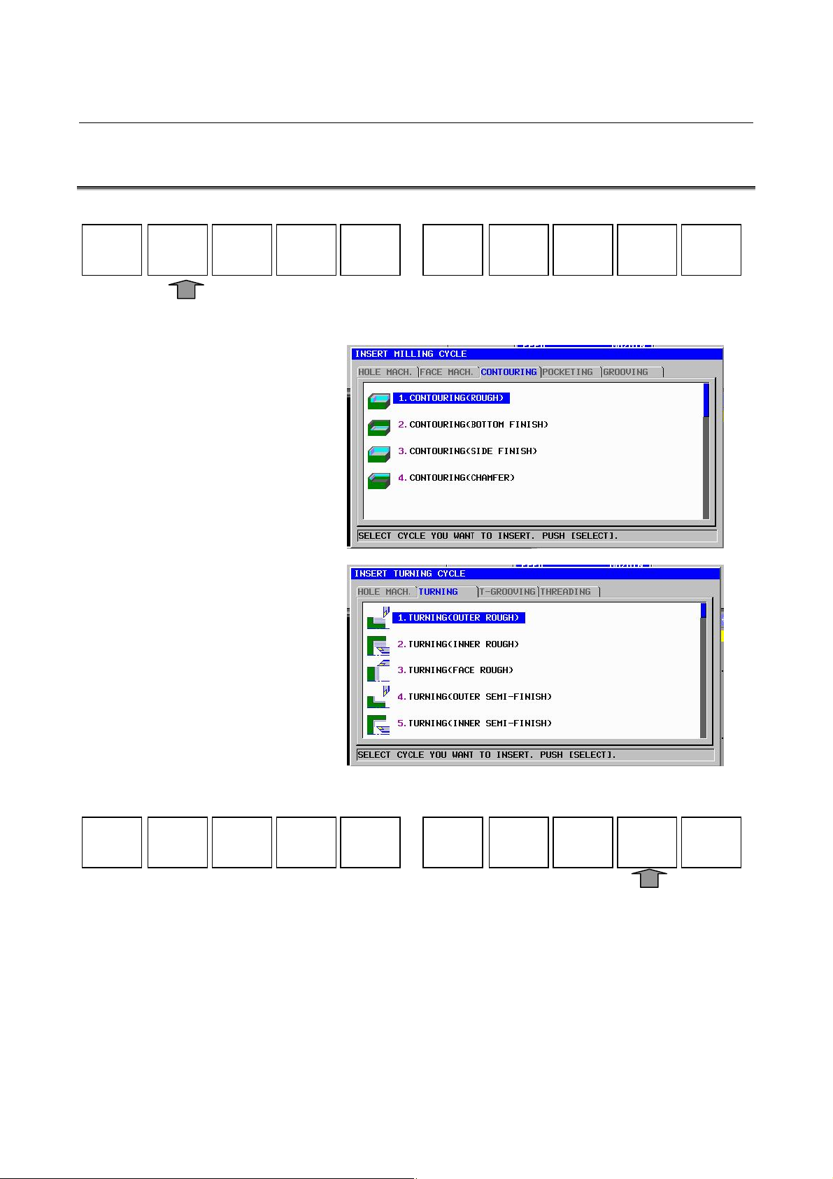
B-63874EN/05 OPERATION 4.EDITING CYCLE MACHINING OPERATIONS
4.2 SELECTING A CYCLE MACHINING TYPE
START
CYCLE
END
ALTERMESCYC
FIGURE
Pressing [CYCLE] displays the cycle machining menu.
M CODE
FIXFRM
The following soft keys are displayed for the cycle machining menu.
CANCELSELECT
Select a cycle machining group, using the ← and → cursor keys, and
then select a cycle machining type from the cycle machining group,
using the ↑ and ↓ cursor keys.
Pressing [SELECT] displays the data entry window for the selected
cycle machining type.
After a menu number is inputted, it is possible that cycle machining is
selected by pressing INPUT key.
- 69 -
Page 92

4.EDITING CYCLE MACHINING OPERATIONS OPERATION B-63874EN/05
NOTE
The scroll bar displayed on the right edge of the
cycle machining menu window indicates the
approximate position of the cursor throughout the
cycle machining menu.
If the scroll bar marker is on the middle of the scroll
bar, therefore, it is likely that part of the cycle
machining menu is hidden behind the window. If
this is the case, pressing the ↓ cursor key makes
the hidden part visible.
- 70 -
Page 93
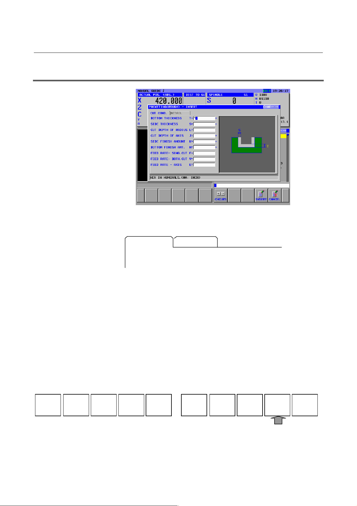
B-63874EN/05 OPERATION 4.EDITING CYCLE MACHINING OPERATIONS
4.3 ENTERING CYCLE MACHINING DATA
The cycle machining data entry window is divided into two sections,
one section for cutting conditions and the other for detailed data.
CUT COND.
Pressing the ← or → cursor key switches between the two sections
and changes the displayed tab. The character in the selected tab is
displayed in blue.
Pressing the ↑ or ↓ cursor key can place the cursor on a desired data
input item.
There are two types of data input items. One type includes those
entered as numbers, and the other type, those selected from a menu
displayed using a soft key. For the first type, the message "KEY IN
NUMERALS." is displayed in the lower section of the window. For
the second type, the message "SELECT SOFT KEY" is displayed.
Necessary data can be entered by referencing a comment for the data
input item and a guide chart displayed in the window.
The following soft keys are displayed for the machining cycle data
window.
When the necessary data has been entered, pressing [INSERT] inserts
a block for the related cycle machining into a machining program.
DETAIL
CHCURS
CANCELINSERT
- 71 -
Page 94

4.EDITING CYCLE MACHINING OPERATIONS OPERATION B-63874EN/05
NOTE
1 Among the data item displayed in the cutting condition
window, there are data should be danger if they are set
automatically such as cutting amount or feedrate. These
data should be entered by an operator always. Other data
are set automatically.
2 Data items displayed in the detail window are usually set
automatically by duplicating the value entered last time. So,
check these automatically set value and modify them if
necessary.
3 Executing cycle machining requires a cycle machining
block and a figure block, which will be explained later.
Once a cycle machining block has been entered, therefore,
be sure to enter a figure block in succession.
4 A data item with an asterisk displayed at its right end has a
default value. You need to enter no data if you accept the
default value.
5 The [CHCURS] soft key is displayed in data entry windows
for cycle machining, figure, and contour programs.
Pressing this soft key can select whether the ← and →
cursor keys are to be used for tab switching or cursor
movement within the entered data. If tab switching is
selected, "Tab ←→" is displayed in the upper right section
of the window. If cursor movement is selected, "Character
←→" is displayed.
- 72 -
Page 95

B-63874EN/05 OPERATION 4.EDITING CYCLE MACHINING OPERATIONS
4.4 SELECTING FIGURES
In usual case, entering a cycle motion block displays continuously
the following figure menu exclusively used for the already entered
cycle machining.
(Example of figure menu for pocketing)
The cycle figure menu window is divided into two sections, one
section for selecting figure and the other for subprogram.
(Example of tab for pocketing)
POCKET FIG SUBPROGRAM
When the figure selection window is selected, the characters of the tab
are displayed in blue. Select a desired figure by moving the cursor
with the cursor keys ↑ and ↓.
CANCELSELECT
Pressing [SELECT] displays a data entry window for the selected
figure.
There are 2 types of figures used for cycle machining, fixed form
figure and free form figure.
The former one is predefined figure such as square and circle, and can
be specified by entering minimum data such as side length or circle
radius.
The later one is specified by entering figures by line or arc along the
figures written on a blue print one by one.
- 73 -
Page 96

4.EDITING CYCLE MACHINING OPERATIONS OPERATION B-63874EN/05
Pressing the → cursor key displays the menu window of subprogram
and the character in the selected tab is displayed in blue.
If some figure blocks were created as subprogram in advance, the
subprogram number and name are displayed in the subprogram menu,
and suitable subprogram can be selected by placing the cursor on it.
Pressing [SELECT] create the block for calling the selected
subprogram as “M98 Pxxxx ;” in the actual part program.
It is specified by program number to be displayed in the subprogram
menu or not.
For turning cycle machining figure, the minimum and maximum
program number of the programs should be used as the subprogram
are set in the parameter No.14720 (TFIGSNO) and No.14721
(TFIGENO).
For milling cycle machining figure, the minimum and maximum
program number of the programs should be used as the subprogram
are set in the parameter No.14722 (MFIGSNO) and No.14723
(MFIGENO).
Subprogram whose number is within these range is displayed in the
subprogram menu for turning or milling cycle figure.
Over 2 figure blocks can be specified continuously for one cycle
machining block. If adding another figure block to the part program in
which cycle machining block and figure block were already inserted,
press [FIGURE] in the soft-keys of program screen and make the
figure menu window display.
But, in this case, all figure menus for all kind of cycle machining are
displayed in one screen. This is different from the figure menu
displayed at the time some cycle machining block is inserted.
START
CYCLE
END
ALTER
FIGURE
M CODE
FIXFRM
NOTE
The scroll bar displayed on the right edge of the
figure menu window indicates the approximate
position of the cursor throughout the figure menu.
If the scroll bar marker is on the middle of the scroll
bar, therefore, it is likely that part of the figure
menu is hidden behind the window. If this is the
case, pressing the ↓ cursor key makes the hidden
part visible.
- 74 -
Page 97

B-63874EN/05 OPERATION 4.EDITING CYCLE MACHINING OPERATIONS
4.5 ENTERING FIXED FORM FIGURE DATA FOR CYCLE
MACHINING
Selecting the fixed form figure displays the data entry window for
cycle machining fixed form data entry window.
(Example of the pocketing fixed form figure)
A data entry window for hole positions, fixed form figures (milling),
turning groove figures, or screw figures (turning) may be extended
over two pages as necessary.
Pressing the ← or → cursor key switches between the two pages. It
also changes the displayed tab.
Pressing the ↑ or ↓ cursor key can place the cursor on a desired data
input item.
There are two types of data input items. One type includes those
entered as numbers, and the other type, those selected from a menu
displayed using a soft key. For the first type, the message "KEY IN
NUMERALS." is displayed in the lower section of the window. For
the second type, the message "SELECT SOFT KEY" is displayed.
Necessary data can be entered by referencing a comment for the data
input item and a guide chart displayed in the window.
The following soft keys are displayed for the fixed form figure data
entry windows.
CONCAV
CANCELINSERT NXTFIG
When the necessary data has been entered, press [INSERT] or
[NXTFIG], then a block for the related figure block is inserted into a
machining program.
Pressing [INSERT] returns to the program window. Pressing
[NXTFIG] displays figure selecting menu again.
- 75 -
Page 98
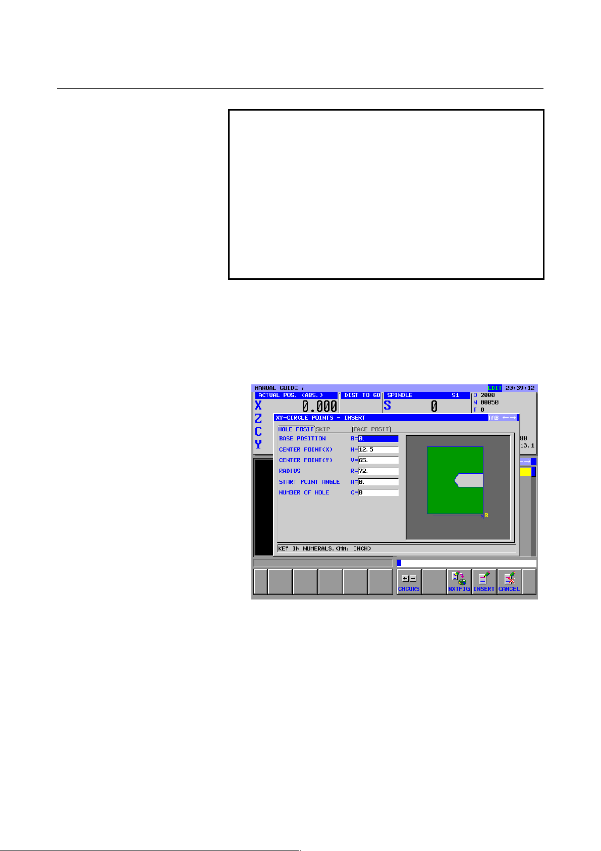
4.EDITING CYCLE MACHINING OPERATIONS OPERATION B-63874EN/05
NOTE
1 More than one figure can be entered in succession
for a single cycle machining type.
Cycle machining is executed for each of the
specified figures sequentially.
2 An ordinary ISO code block can be entered
between cycle machining and figure blocks. If this
is done, no machining operation takes place in the
cycle machining block. Instead, the ISO code block
entered before the figure block is executed. Cycle
machining is executed only in the figure block after
the ISO code block has been executed.
Output as a subprogram
When bit 1 of parameter No. 14851 is set to 1, fixed form figure data
can be output as a subprogram. The operation procedure is described
below.
<1> Press the [INSERT] soft key in the fixed form figure data input
window.
- 76 -
Page 99

B-63874EN/05 OPERATION 4.EDITING CYCLE MACHINING OPERATIONS
<2> A screen for selecting fixed form figure data as a subprogram is
displayed as shown below.
<3> When creating fixed form figure data as a subprogram, select
"CREATE AS SUB PROGRAM".
<4> If a comment is entered, the entered comment is added to the
M98P**** block of the main program and the subprogram at the
time of program output.
<5> Pressing the [OK] soft key outputs a created fixed form figure
program as a subprogram to the machining program.
- 77 -
Page 100

4.EDITING CYCLE MACHINING OPERATIONS OPERATION B-63874EN/05
4.6 ENTERING ARBITRARY FIGURE DATA FOR CYCLE
MACHINING
For cycle machining, an arbitrary figure consisting of circles and
straight lines can be entered by performing automatic calculation on
entered data to obtain the end point of each figure even if no end point
is specified on the drawing.
(1) Entering start points
Be sure to enter a start point for the beginning of an arbitrary
figure.
After entering necessary data, press [OK].
LINE
ARC
ARC
(2) Selecting a figure
A menu for figure selection is displayed on soft keys as shown
below. Select whatever is necessary.
CR
CC
ALTER
DELETE
RECALC
CANCELCREATE
(3) Entering figure data
When a figure is selected, a figure data entry window appears. In
this window, enter the figure data specified on the drawing.
There are two types of data input items. One type includes those
entered as numbers, and the other type, those selected from a
menu displayed using a soft key. For the first type, the message
"KEY IN NUMERALS." is displayed in the lower section of the
window. For the second type, the message "SELECT SOFT
KEY" is displayed.
After entering the necessary data, press [OK].
- 78 -
 Loading...