

Page 1

Open CNC
Basic Operation Package 1
Operator's Manual
B-62994EN/02
Page 2

• No part of this manual may be reproduced in any form.
• All specifications and designs are subject to change without notice.
The products in this manual are controlled based on Japan’s “Foreign Exchange and
Foreign Trade Law”. The export from Japan may be subject to an export license by the
government of Japan.
Further, re-export to another country may be subject to the license of the government of
the country from where the product is re-exported. Furthermore, the product may also be
controlled by re-export regulations of the United States government.
Should you wish to export or re-export these products, please contact FANUC for advice.
In this manual we have tried as much as possible to describe all the various matters.
However, we cannot describe all the matters which must not be done, or which cannot be
done, because there are so many possibilities.
Therefore, matters which are not especially described as possible in this manual should be
regarded as ”impossible”.
This manual contains the program names or device names of other companies, some of
which are registered trademarks of respective owners. However, these names are not
followed by ® or ™ in the main body.
Page 3

Warnings and notices for
GFLE-003
this publication
Warning
In this manual we have tried as much as possible to describe all the various
matters. However, we cannot describe all the matters which must not be done,
or which cannot be done, because there are so many possibilities.
Therefore, matters which are not especially described as possible in this
manual should be regarded as “impossible”.
Notice
This document is based on information available at the time of its publication. While efforts have
been made to be accurate, the information contained herein does not purport to cover all details or
variations in hardware or software, nor to provide every contingency in connection with
installation, operation, or maintenance. Features may be described herein which are not present in
all hardware and software systems. FANUC CNC assumes no obligation of notice to
holders of this document with respect to changes subsequently made.
FANUC CNC makes no representation or warranty, expressed, implied, or statutory with
respect to, and assumes no responsibility for accuracy, completeness, sufficiency, or usefulness of
the information contained herein. No warranties of merchantability or fitness for purpose shall
apply.
The following are Registered Trademarks of FANUC CNC
CIMPLICITY® Genius®
The following are Trademarks of FANUC CNC
Alarm Master
CIMSTAR
Field Control
Genet
Helpmate
LogicMaster
Modelmaster
PowerMotion
ProLoop
PROMACRO
Series Five
Series 90
Series One
Series Six
Series Three
VuMaster
Workmaster
© Copyright 1998 FANUC Ltd.
Authorized Reproduction FANUC CNC Europe S.A.
All Rights Reserved
No part of this manual may be reproduced in any form.
All specifications and designs are subject to change without notice.
Page 4

Page 5

SAFETY PRECAUTIONS
This manual includes safety precautions for protecting the user and preventing damage to
the machine. Precautions are classified into Warnings and Cautions according to their
bearing on safety. Also, supplementary information is described as Notes. Read the
Warnings, Cautions, and Notes thoroughly before attempting to use the machine.
WARNING
Applied when there is a danger of the user being injured or when there
is a danger of both the user being injured and the equipment being
damaged if the approved procedure is not observed.
CAUTION
Applied when there is a danger of the equipment being damaged, if the
approved procedure is not observed.
NOTE
Notes is used to indicate supplementary information other than
Warnings and Cautions.
¡ Read this manual carefully, and store it in a safe place.
s-1
Page 6

SAFETY PRECAUTIONS B-62994EN/02
General Warnings and Cautions
WARNING
1. Never attempt to machine a workpiece without first checking the
operation of the machine. Before starting a production run, ensure
that the machine is operating correctly by performing a trial run
using, for example, the single block, feedrate override, or machine
lock function, or by operating the machine with neither a tool nor
workpiece mounted. Failure to confirm the correct operation of the
machine may result in the machine behaving unexpectedly,
possibly causing damage to the workpiece and/or machine itself,
or injury to the user.
2. Before operating the machine, thoroughly check the entered data.
Operating the machine with incorrectly specified data may result in
the machine behaving unexpectedly, possibly causing damage to
the workpiece and/or machine itself, or injury to the user.
3. Ensure that the specified feedrate is appropriate for the intended
operation. Generally, for each machine, there is a maximum
allowable feedrate. The appropriate feedrate varies with the
intended operation. Refer to the manual provided with the
machine to determine the maximum allowable feedrate. If a
machine is run at other than the correct speed, it may behave
unexpectedly, possibly causing damage to the workpiece and/or
machine itself, or injury to the user.
4. When using a tool compensation function, thoroughly check the
direction and amount of compensation.
Operating the machine with incorrectly specified data may result in
the machine behaving unexpectedly, possibly causing damage to
the workpiece and/or machine itself, or injury to the user.
5. The parameters for the CNC and PMC are factory-set. Usually,
there is no need to change them. When, however, there is no
alternative other than to change a parameter, ensure that you fully
understand the function of the parameter before making any
change.
Failure to set a parameter correctly may result in the machine
behaving unexpectedly, possibly causing damage to the workpiece
and/or machine itself, or injury to the user.
s-2
Page 7

B-62994EN/02 SAFETY PRECAUTIONS
CAUTION
1. The operator's manual for Basic Operation Package 1 describes all
the basic functions of the CNC unit, including the optional
functions. The selected optional functions vary with the machine.
Some functions described in the manual may not, therefore, be
supported by your machine. Check the machine specifications
before using Basic Operation Package 1.
2. Some machine operations and screen functions are implemented
by the machine tool builder. For an explanation of their usage and
related notes, refer to the manual provided by the machine tool
builder.
For example:
l On some machines, executing a tool function causes the tool
change unit to operate. When executing a tool function on such
a machine, stand well clear of the tool change unit. Otherwise,
there is a danger of injury to the operator.
l Many auxiliary functions trigger physical operations, such as
rotation of the spindle. Before attempting to use an auxiliary
function, therefore, ensure that you are fully aware of the
operation to be triggered by that function.
NOTE
l Command programs, parameters, and variables are stored in
nonvolatile memory in the CNC. Generally, the contents of memory
are not lost by a power on/off operation. However, the contents of
memory may be erased by mistake, or important data in nonvolatile
memory may have to be erased upon recovering from a failure.
To enable the restoration of data as soon as possible if such a
situation arises, always make a backup of the data in advance.
s-3
Page 8

SAFETY PRECAUTIONS B-62994EN/02
Warnings and Cautions Relating to Basic
Operation Package 1
Warnings and cautions relating to Basic Operation Package 1 are explained in
this manual. Before using the function, read this manual thoroughly to
become familiar with the provided Warnings, Cautions, and Notes.
On the next page, the points to be noted when Basic Operation Package 1 is
used are summarized. These points are not explained in Chapter 1 and the
subsequent chapters of this manual. Read this part before attempting to use
the function.
s-4
Page 9

B-62994EN/02 SAFETY PRECAUTIONS
Important Notice
The following summarizes the points to be noted when Basic Operation
Package 1 is used. Before attempting to use Basic Operation Package 1, read
the following:
CAUTION
l This manual does not explain in detail those operations and
parameters that vary from one CNC model to another and which vary
with options. For an explanation of such operations and parameters,
refer to the relevant CNC manual and the manual supplied by the
machine tool builder.
l This manual describes as many reasonable variations in usage as
possible. It cannot address every combination of features, options,
and commands that should not be attempted. If a particular
combination of operations is not described, it should not be
attempted.
s-5
Page 10

B-62994EN/02
CONTENTS
SAFETY PRECAUTIONS......................................................................................................................... s-1
General Warnings and Cautions
Warnings and Cautions Relating to Basic Operation Package 1
Important Notice
PREFACE...............................................................................................................................................................p-1
Basic Operation Package 1 Features and Restrictions
Contents of the Product Package
Organization of This Manual
Notation Conventions
CONTENTS...........................................................................................................................................................c-1
1. SETUP................................................................................................................................................................. 1
1.1 Operating Environment..........................................................................................................................2
1.2 Installing Basic Operation Package 1 .................................................................................................. 4
1.3 Uninstalling Basic Operation Package 1.............................................................................................7
2. BASIC KNOWLEDGE.......................................................................................................................... 9
2.1 Starting and Terminating Basic Operation Package 1.....................................................................10
2.1.1 Starting Basic Operation Package 1...............................................................................................10
2.1.2 Terminating Basic Operation Package 1........................................................................................11
2.2 Window Names and Functions...........................................................................................................13
2.3 Selecting and Positioning Windows...................................................................................................21
2.3.1 Selecting a window........................................................................................................................21
2.3.2 Positioning a window.....................................................................................................................22
2.4 Selecting a Path..................................................................................................................................... 24
2.5 Displaying Version Information......................................................................................................... 25
3. SETTING THE PARAMETERS REQUIRED
TO USE BASIC OPERATION PACKAGE 1......................................................................26
3.1 Setting the CNC Parameters................................................................................................................27
3.2 Specifying a Node................................................................................................................................. 29
4. POSITION DISPLAY............................................................................................................................30
4.1 Overall Position Display......................................................................................................................31
4.2 Displaying the Relative Position ........................................................................................................ 33
4.2.1 Resetting relative coordinates........................................................................................................35
4.2.2 Presetting relative coordinates.......................................................................................................36
c-1
Page 11

CONTENTS B-62994EN/02
4.2.3 Setting the machine position to the floating reference position......................................................38
4.2.4 Presetting the workpiece coordinate system...................................................................................39
4.3 Displaying the Absolute Position.......................................................................................................42
4.4 Displaying the Machine Position........................................................................................................ 44
4.5 Displaying the Distance to Go............................................................................................................45
4.6 Displaying the Amount of Handle Interruption................................................................................ 46
4.6.1 Canceling the amount of handle interruption.................................................................................47
4.7 Displaying the Operating Monitor......................................................................................................49
4.8 Displaying the Machining Time and Machined Parts Count ......................................................... 50
5. NC PROGRAM..........................................................................................................................................52
5.1 Editing a NC Program.......................................................................................................................... 53
5.1.1 Getting a program from the NC ..................................................................................................... 56
5.1.2 Writing a NC program back to the NC .......................................................................................... 58
5.1.3 Inserting a NC program from a disk............................................................................................... 59
5.1.4 Writing a NC program to a disk.....................................................................................................60
5.1.5 Finding a character string in a NC program................................................................................... 61
5.1.6 Replacing a character string in a NC program ............................................................................... 62
5.1.7 Selecting character strings in a NC program..................................................................................63
5.1.8 Cutting character strings from a NC program................................................................................64
5.1.9 Copying character strings from a NC program .............................................................................. 66
5.1.10 Pasting character strings into a NC program..................................................................................67
5.1.11 Inserting sequence numbers into a NC program ............................................................................ 68
5.1.12 Entering a coordinate value into a NC program.............................................................................71
5.1.13 Displaying the top of a NC program.............................................................................................. 73
5.1.14 Displaying the end of a NC program..............................................................................................74
5.1.15 Stamping the machining time.........................................................................................................75
5.2 Editing an MDI Program......................................................................................................................77
5.2.1 Finding a character string in an MDI program...............................................................................79
5.2.2 Replacing a character string in an MDI program........................................................................... 80
5.2.3 Selecting character strings in an MDI program.............................................................................. 81
5.2.4 Cutting character strings from an MDI program............................................................................ 82
5.2.5 Copying character strings from an MDI program..........................................................................84
5.2.6 Pasting character strings into an MDI program.............................................................................. 85
5.2.7 Inserting sequence numbers into an MDI program........................................................................86
5.2.8 Displaying the top of an MDI program..........................................................................................88
5.2.9 Displaying the end of an MDI program ......................................................................................... 89
5.3 Displaying the NC Program Directory...............................................................................................90
5.3.1 Copying a NC program.................................................................................................................. 92
5.3.2 Deleting a NC program.................................................................................................................. 94
5.3.3 Selecting a NC program to be executed......................................................................................... 95
5.3.4 Changing a NC program comment................................................................................................. 97
5.3.5 Changing the NC program directory contents................................................................................98
c-2
Page 12

B-62994EN/02 CONTENTS
5.4 Checking the Program Currently Being Executed.........................................................................100
5.4.1 Rewinding the tape to the beginning of the NC program............................................................. 101
5.4.2 Searching for a sequence number.................................................................................................103
5.5 Displaying the Current and Next Blocks of the NC Program Being Executed ......................... 105
5.6 Restarting a NC Program................................................................................................................... 106
5.6.1 Setting the axis order of movement to the program restart position............................................. 108
5.6.2 Searching for a sequence/block number....................................................................................... 109
5.7 Displaying the Machining Times......................................................................................................112
5.8 Displaying the B-Axis Operating Status..........................................................................................114
6. SETTING...................................................................................................................................................... 116
6.1 Setting Data..........................................................................................................................................117
6.2 Operating Time, Parts Count, and Timer Settings......................................................................... 121
6.3 Tool Offset Settings............................................................................................................................ 124
6.3.1 Entering a relative coordinate value as the tool offset data..........................................................127
6.3.2 Entering a measured value as the tool offset data ........................................................................ 129
6.3.3 Clearing all tool offset data..........................................................................................................130
6.4 Custom Macro Variable Settings...................................................................................................... 132
6.4.1 Displaying local variables............................................................................................................134
6.4.2 Common variable 1 settings.........................................................................................................136
6.4.3 Common variable 2 settings.........................................................................................................137
6.4.4 Entering a relative coordinate value as a macro variable............................................................. 139
6.4.5 Clearing all custom macro variables............................................................................................140
6.4.6 Setting a blank in a macro variable.............................................................................................. 142
6.5 Workpiece Origin Offset Settings....................................................................................................143
6.5.1 Entering a measured value as workpiece origin offset data..........................................................145
6.6 Tool Life Management Data Settings.............................................................................................. 147
6.6.1 Adding a tool to a tool group included in the tool life management data..................................... 151
6.6.2 Changing the life status of a tool included in the tool life management data
(for machining center systems) .................................................................................................... 154
6.6.3 Changing the life status of a tool included in the tool life management data
(for lathe systems)........................................................................................................................157
6.6.4 Setting the life counter data included in the tool life management data
(for machining center systems) .................................................................................................... 159
6.6.5 Setting the life counter data included in the tool life management data (for lathe systems)......... 161
6.6.6 Deleting a tool from a tool group included in the tool life management data
(for machining center systems) .................................................................................................... 163
6.6.7 Deleting a tool from a tool group included in the tool life management data
(for lathe systems)........................................................................................................................165
6.7 Software Operator's Panel Settings..................................................................................................167
6.8 Workpiece Coordinate System Shift Settings................................................................................. 169
6.9 P-Code Macro Variable Settings......................................................................................................172
6.9.1 Displaying local variables............................................................................................................174
6.9.2 Common variable 1 settings.........................................................................................................175
c-3
Page 13

CONTENTS B-62994EN/02
6.9.3 Common variable 2 settings.........................................................................................................176
6.9.4 P-code variable 1 settings ............................................................................................................ 177
6.9.5 P-code variable 2 settings ............................................................................................................ 178
6.9.6 Setting a blank in a P-code macro variable.................................................................................. 179
6.10 Chopping Data Settings ..................................................................................................................... 180
6.11 Chuck and Tailstock Barrier Settings ..............................................................................................182
6.12 B-Axis Tool Offset Settings..............................................................................................................186
6.13 Tool Post Interference Check Settings.............................................................................................189
6.14 2-Path Interference Check Settings .................................................................................................. 192
7. SYSTEM........................................................................................................................................................ 195
7.1 Setting Parameters .............................................................................................................................. 196
7.2 Displaying the Diagnosis Screen...................................................................................................... 198
7.3 Displaying the System Configuration.............................................................................................. 200
7.3.1 Outputting the system configuration data to a file........................................................................201
7.4 Data Input/Output ............................................................................................................................... 203
7.4.1 Setting parameters for input/output..............................................................................................204
7.4.2 Displaying lists of various data files ............................................................................................ 208
7.4.3 Entering different types of data....................................................................................................210
7.4.4 Outputting different types of data ................................................................................................ 220
7.4.5 Deleting data files........................................................................................................................229
7.4.6 Renaming different types of data files..........................................................................................231
7.5 Setting Pitch Error Compensation Data........................................................................................... 233
7.6 Setting Servo Setting Data................................................................................................................. 235
7.7 Setting Servo Tuning Data ................................................................................................................237
7.8 Setting Spindle Setting Data .............................................................................................................239
7.9 Setting Spindle Tuning Data.............................................................................................................241
7.10 Collecting Waveform Diagnosis Data .............................................................................................243
7.10.1 Setting data for waveform diagnosis............................................................................................ 245
7.10.2 Collecting waveform diagnosis sampling data............................................................................. 250
7.11 Displaying Waveform Diagnosis Graphs........................................................................................252
7.11.1 Selecting the waveform diagnosis data to be displayed ............................................................... 257
7.11.2 Saving waveform diagnosis data into a file.................................................................................. 259
7.12 Displaying the PMC Status Screen .................................................................................................. 260
7.13 Displaying the PMC Alarm Screen.................................................................................................. 262
7.14 Setting the PMC Counter................................................................................................................... 263
7.15 Setting the PMC Timer ......................................................................................................................265
7.16 Setting the PMC Keep Relay ............................................................................................................ 267
7.17 Setting PMC Data ............................................................................................................................... 269
7.17.1 Setting the data table of PMC data............................................................................................... 271
7.17.2 Setting the group data of PMC data............................................................................................. 273
7.17.3 Deleting and initializing all PMC data.........................................................................................278
7.18 Displaying the Operation History..................................................................................................... 280
7.18.1 Clearing the operation history information .................................................................................. 282
c-4
Page 14

B-62994EN/02 CONTENTS
7.18.2 Setting I/O signals for the operation history.................................................................................284
8. MESSAGES................................................................................................................................................286
8.1 Displaying Alarm Messages.............................................................................................................. 287
8.2 Displaying Operator Messages......................................................................................................... 288
8.3 Displaying the Alarm Message History........................................................................................... 289
8.3.1 Deleting the entire alarm message history.................................................................................... 290
9. MILLING ANIMATION FUNCTION (OPTION)........................................................ 292
9.1 Setting Tools for Machining-in-Progress Drawing........................................................................ 293
9.1.1 Registering tools for machining-in-progress drawing .................................................................. 294
9.1.2 Modifying tool data for machining-in-progress drawing..............................................................296
9.1.3 Deleting tools for machining-in-progress drawing.......................................................................297
9.1.4 Saving tool data for machining-in-progress drawing into a file ................................................... 299
9.1.5 Reading tool data for machining-in-progress drawing from a file................................................300
9.2 Performing Machining-in-Progress Drawing.................................................................................. 302
9.2.1 Settings for machining-in-progress drawing ................................................................................303
9.2.2 Starting machining-in-progress drawing ...................................................................................... 310
10. CUSTOM...................................................................................................................................................... 313
10.1 Displaying the OLE Object Screen .................................................................................................. 314
10.1.1 Example for inserting an OLE object........................................................................................... 316
11. CUSTOMIZATION.............................................................................................................................. 322
11.1 Customizing General Settings for Basic Operation Package 1 .................................................... 323
11.1.1 Setting general options for Basic Operation Package 1 ............................................................... 325
11.1.2 Setting soft keys........................................................................................................................... 327
11.1.3 Setting screen colors....................................................................................................................330
11.1.4 Setting the path number output option.........................................................................................332
11.2 Customizing Screens ..........................................................................................................................333
11.2.1 Creating custom screens............................................................................................................... 334
11.2.2 Changing the order in which screens appear................................................................................341
11.2.3 Deleting screens........................................................................................................................... 342
11.2.4 Showing or hiding chapters.......................................................................................................... 343
11.2.5 Setting soft keys as empty............................................................................................................345
11.3 Customizing Screen Objects ............................................................................................................. 347
11.3.1 Creating custom screen objects....................................................................................................349
11.3.2 Changing settings of screen objects ............................................................................................. 355
11.3.3 Deleting screen objects................................................................................................................356
11.4 Customizing Message Languages.....................................................................................................358
11.4.1 Installing message languages ....................................................................................................... 359
11.4.2 Switching the message language.................................................................................................. 360
11.4.3 Changing the order in which message languages are listed.......................................................... 362
c-5
Page 15

CONTENTS B-62994EN/02
11.4.4 Uninstalling message languages................................................................................................... 363
11.5 Customizing Alarm Messages...........................................................................................................364
11.6 Integrating DNC Operation Management Package........................................................................367
APPENDIX 1 REQUIRED NC SETTING FOR EACH BASIC OPERATION
PACKAGE 1 SCREEN.............................................................................................. 371
APPENDIX 2 BACKING UP THE SETTING FILE...........................................................419
APPENDIX 3 CREATING AN ActiveX CONTROL........................................................... 420
APPENDIX 4 SWITCHING THE MESSAGE LANGUAGE........................................430
APPENDIX 5 MESSAGE FILE GENERATOR...................................................................... 434
c-6
Page 16

B-62994EN/02 PREFACE
PREFACE
Thank you for purchasing the FANUC Basic Operation Package 1.
FANUC Basic Operation Package 1 (called Basic Operation Package 1
hereinafter) allows the user to perform basic CNC and PMC operations in an
Open CNC environment.
Basic Operation Package 1 is supported by Microsoft Windows. This
manual does not explain the basic common operations of Windows.
Users who are using Windows for the first time should read the manuals on
Windows first to become familiar with the basic operation of Windows.
Read this manual thoroughly to ensure the correct use of Basic Operation
Package 1.
NOTE
The purchased software product can be copied within the plant, as
required. The machine tool builder should ship machines together with
a backup copy of the software product.
FANUC holds the copyright on this software product. Redistributing the
entire software product, or part of it, to a third party to develop an
application is not allowed.
Microsoft, Windows, and Visual Basic are registered trademarks of
Microsoft Corporation. ActiveX and OLE are trademarks of
Microsoft Corporation.
Basic Operation Package 1 Features and Restrictions
Basic Operation Package 1 has the following features:
Features
l Implements the basic CNC and PMC operations under Windows, thus
providing a more user-friendly operating environment.
l Offers operability such that current users of FANUC CNCs can quickly
become familiar with the system.
l Allows customization to improve operability, such as modifying the
screen settings or adding or deleting a screen.
p-1
Page 17

PREFACE B-62994EN/02
l Provides each screen as an ActiveX component, such that it can be
embedded into a program developed with Visual Basic 4.0/5.0.
The following restrictions are imposed on Basic Operation Package 1:
Restrictions
l This software is designed to be used with a personal computer connected
to High Speed Serial Bus Type 2, the FS160i/180i/210i having personal
computer functions, a personal computer in which the NC Board has
been installed, or Intelligent Terminal Type 2. It cannot be used with the
MMC-IV, a personal computer connected to High Speed Serial Bus Type
1, or Intelligent Terminal Type 1.
l This software supports the following CNCs:
FS150-MB/TB/TTB (systems having up to 15 axes)
FS160-MB/TB/MMB/TTB, FS180-MB/TB/TTB, FS210-MB/TB
FS160-MC/TC/MMC/TTC, FS180-MC/TC/TTC
FS160i-MA/TA, FS180i-MA/TA, FS210i-MA/TA
Power Mate-D/H, Power Mate i-D/H
•• Following CNCs connected to a commercial personal computer via
High Speed Serial Bus Type 2
FS15-MB/TB/TTB (systems having up to 15 axes)
FS16-MB/TB/MMB/TTB, FS18-MB/TB/TTB, FS21-MB/TB
FS16-MC/TC/MMC/TTC, FS18-MC/TC/TTC
FS16i-MA/TA, FS18i-MA/TA, FS21i-MA/TA
Power Mate-D/H, Power Mate i-D/H
•• FA160i-MA/TA, FS180i-MA/TA, and FS210i-MA/TA having
personal computer functions
•• NC Board M/T
l This software cannot be used to develop or debug ladder programs. To
develop or debug ladder programs, obtain the following options:
•• When using a CNC other than the Power Mate-D/H: Ladder Editing
Package
•• When using the Power Mate-D/H: FAPT LADDER II
p-2
Page 18

B-62994EN/02 PREFACE
Contents of the Product Package
This product package consists of the following:
lFloppy disks
FANUC Basic Operation Package 1 (A02B-0207-K750#ZZ07)
NOTE
Read the Release Note (README.TXT), provided on the first floppy
disk of the product package. It provides detailed information on this
product package and information not described in the operator's
manual.
Organization of This Manual
This manual is organized as follows:
SAFETY PRECAUTIONS
Explains the general precautions which must be observed to ensure safety
when using Basic Operation Package 1.
PREFACE
Briefly explains the features of Basic Operation Package 1. Also explains
how to use information on the usage of Basic Operation Package 1,
including this manual.
1. SETUP
Explains how to set up the environment for using Basic Operation
Package 1 and how to prepare Basic Operation Package 1 for use.
2. BASIC KNOWLEDGE
Provides basic information with which the user should be familiar before
attempting to use Basic Operation Package 1.
3. SETTING THE PARAMETERS REQUIRED TO USE BASIC OPERATION
PACKAGE 1
Explains how to set the parameters required to display the screens of
Basic Operation Package 1.
4. POSITION DISPLAY
Explains how to display positions, such as the current position, for the
program that is currently being executed.
5. NC PROGRAM
Explains how to display, edit, and check NC programs.
6. SETTING
Explains how to set data.
p-3
Page 19

PREFACE B-62994EN/02
7. SYSTEM
Explains how to display and set system-related information, and how to
input and output different types of data.
8. MESSAGES
Explains how to display alarms and other messages.
9. MILLING ANIMATION FUNCTION (OPTION)
Explains how to perform machining-in-progress drawing when a milling
machine tool is used.
10.CUSTOM
Explains how to insert an OLE object.
11.CUSTOMIZATION
Explains how to customize Basic Operation Package 1.
APPENDIX
Provides supplementary information to be read as required, such as how
to back up the setting file.
Notation Conventions
The following explains the notation conventions used in this manual:
lMenu, command, and screen notations
Example Explanation
[File] menu Menu names are enclosed in brackets [ ].
[Setting...] Command names are enclosed in brackets [ ].
[Program Edit] screen Screen names (displayed on the title bars) are
<OK> button Command buttons on the display are enclosed
lKey notations and operation
Example Explanation
[Enter] key Key names are enclosed in brackets [ ].
[Ctrl]+[Tab] keys When keys are to be pressed and held down
Direction keys The [→], [←], [↑], and [↓] keys are
enclosed in brackets [ ].
in angle brackets < >.
sequentially, the keys are indicated by
connecting them with +, as shown on the left.
collectively called the direction keys.
p-4
Page 20

B-62994EN/02 PREFACE
lMouse operations
Example Explanation
Click Press a mouse button, then release it
immediately.
Double-click Click a mouse button twice in quick
succession.
Drag Move the mouse while holding down a mouse
button, then release the button at a desired
location.
lFolders
This manual refers to directories and folders collectively as folders.
lSample screens
The screens shown in this manual are examples of the standard system
supplied by FANUC. Note that the screen layouts and displayed file names
may vary with the equipment being used and according to customization.
Soft keys or screens are not displayed if the equipment being used does not
support the corresponding functions (for example, some functions are
supported only by machining center systems) or if the CNC options for the
corresponding functions are not installed.
lCNC units
Unless otherwise specified, FS16/18/21 refers to the FS16/18/21MB/TB/MMB/TTB, FS16/18-MC/TC/MMC/TTC, FS160/180/210MB/TB/MMB/TTB, FS160/180-MC/TC/MMC/TTC, FS16i/18i/21i-
MA/TA, and FS160i/180i/210i-MA/TA. FS15 also refers to the FS15MB/TB/TTB and FS150-MB/TB/TTB, while Power Mate refers to the
Power Mate-D/H and Power Mate i-D/H.
p-5
Page 21

B-62994EN/02 1. SETUP
1 SETUP
This chapter explains how to set up the environment for operating Basic
Operation Package 1 and how to prepare Basic Operation Package 1 for use.
-1-
Page 22

1. SETUP B-62994EN/02
1.1 Operating Environment
The software operating environment for Basic Operation Package 1 is
described below.
u Computer
A personal computer connected to High Speed Serial Bus Type 2, the
FS160i/180i/210i having personal computer functions, a personal computer
in which the NC Board has been installed, or Intelligent Terminal Type 2
l Environmental requirements
Windows 95/Windows 98
WIN32 version
• Pentium processor with clock frequency of 75 MHz or higher
• At least 16MB of memory
WIN16 version
• i486DX2 or better CPU with clock frequency of 50 MHz or higher
• At least 12MB of memory
Windows NT 4.0
WIN32 version
• Pentium processor with clock frequency of 120 MHz or higher
• At least 32MB of memory
WIN16 version
Not supported
Windows 3.1
WIN32 version
Not supported
WIN16 version
• i486DX2 or better CPU with clock frequency of 50 MHz or higher
• At least 20MB of memory
l Recommended operating environment
Windows 95/Windows 98
WIN32 version
• Pentium processor with clock frequency of 120 MHz or higher
• At least 32MB of memory
WIN16 version
• i486DX2 or better CPU with clock frequency of 75 MHz or higher
• At least 24MB of memory
-2-
Page 23

B-62994EN/02 1. SETUP
Windows NT 4.0
WIN32 version
• Pentium processor with clock frequency of 150 MHz or higher
• At least 64MB of memory
WIN16 version
Not supported
Windows 3.1
WIN32 version
Not supported
WIN16 version
• i486DX2 or better CPU with clock frequency of 75 MHz or higher
• At least 24MB of memory
l Required free space on hard disk
At least 20MB
NOTE
FANUC recommends that Basic Operation Package 1 be operated
under Windows 95/Windows 98 or Windows NT 4.0.
-3-
Page 24

1. SETUP B-62994EN/02
1.2 Installing Basic Operation Package 1
This section describes how to install Basic Operation Package 1.
NOTE
Before Basic Operation Package 1 can be installed, operations such as
driver installation and setting must be performed according to the
operating environment. For details, refer to the following documents:
l Personal computer connected to High Speed Serial Bus Type 2, the
FS160i/180i/210i having personal computer functions, or Intelligent
Terminal Type 2
•• Release Note (README.TXT) on the driver library floppy disk
(A02B-0207-K730#ZZ07-1)
or
•• Release Note (README.TXT) on the driver disk (A02B-0207K791#ZZ07-1)
l NC Board
•• Lathe system
Release Note (README.TXT) on Disk 1 of the setup disks (A02B0234-H500)
•• Machining center system
Release Note (README.TXT) on Disk 1 of the setup disks (A02B0235-H500)
Procedure
ll WIN32 version
•• Installing Basic Operation Package 1
1. Insert the disk (A02B-0207-K750#ZZ07-2) into the floppy disk
drive.
2. Click the [Start] button.
3. Select [Run].
4. Enter <drive-name>:SETUP, then click the <OK> button. (<drive-
name> is the name of the 3.5-inch floppy disk drive.)
5. Perform installation according to the displayed messages.
6. Upon the completion of installation, restart the personal computer.
The setup program of Basic Operation Package 1 installs the English
version by default. To display non-English messages (Japanese,
German, French, Italian, or Spanish), subsequently install the nonEnglish message environment, as follows.
-4-
Page 25

B-62994EN/02 1. SETUP
NOTE
Before installing the Japanese message environment, start and
terminate Basic Operation Package 1 at least once. For an
explanation of how to start and terminate Basic Operation
Package 1, see Section 2.1, "Starting and Terminating Basic
Operation Package 1."
Non-English messages can be displayed only under Windows of
the target language version. For example, Japanese messages
can be displayed only under Japanese Windows and German
messages can be displayed only under German Windows.
•• Installing the non-English message environment
1. Insert the disk (A02B-0207-K750#ZZ07-5) into the floppy disk
drive.
2. Click the [Start] button.
3. Select [Run].
4. Enter the data corresponding tohe target language as listed below,
then click the <OK> button.
Japanese <drive-name> : \JPN\ADDLANG
German <drive-name> : \GER\ADDLANG
French <drive-name> : \FRE\ADDLANG
Italian <drive-name> : \ITA\ADDLANG
Spanish <drive-name> : \SPA\ADDLANG
<drive-name> is the name of the 3.5-inch floppy disk drive.
5. Perform installation according to the displayed messages.
ll WIN16 version
•• Installing Basic Operation Package 1
1. Insert the disk (A02B-0207-K750#ZZ07-8) into the floppy disk
drive.
2. Click the [Start] button.
(For Windows 3.1, select [File].)
3. Select [Run].
4. Enter <drive-name>:SETUP, then click the <OK> button. (<drive-
name> is the name of the 3.5-inch floppy disk drive.)
5. Perform installation according to the displayed messages.
6. Upon the completion of installation, restart the personal computer.
The setup program of Basic Operation Package 1 installs the English
version by default. To display non-English messages (Japanese,
German, French, Italian, or Spanish), subsequently install the nonEnglish message environment, as follows.
-5-
Page 26

1. SETUP B-62994EN/02
NOTE
Before installing the non-English message environment, start
and terminate Basic Operation Package 1 at least once. For an
explanation of how to start and terminate Basic Operation
Package 1, see Section 2.1, "Starting and Terminating Basic
Operation Package 1."
•• Installing the non-English message environment
1. Insert the disk (A02B-0207-K750#ZZ07-9) into the floppy disk
drive.
2. Click the [Start] button.
(For Windows 3.1, select [File].)
3. Select [Run].
4. Enter the data corresponding to the target language as listed below,
then click the <OK> button.
Japanese <drive-name> : \JPN\ADDLANG
German <drive-name> : \GER\ADDLANG
French <drive-name> : \FRE\ADDLANG
Italian <drive-name> : \ITA\ADDLANG
Spanish <drive-name> : \SPA\ADDLANG
<drive-name> is the name of the 3.5-inch floppy disk drive.
5. Perform installation according to the displayed messages.
-6-
Page 27
B-62994EN/02 1. SETUP
1.3 Uninstalling Basic Operation Package 1
This section describes how to uninstall Basic Operation Package 1.
NOTE
Uninstallation is supported only by the WIN32 version of Basic
Operation Package 1.
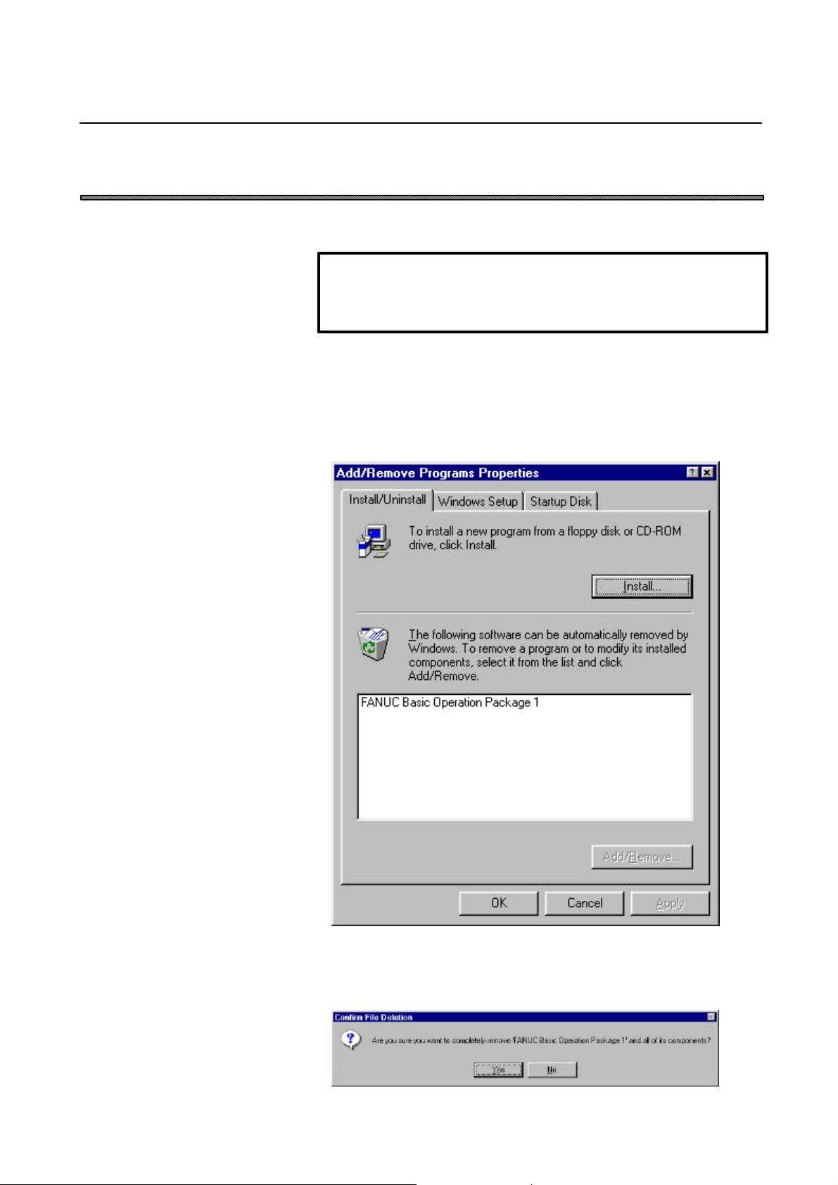
Procedure
1. Click the [Start] button.
2. Choose [Settings], then choose the [Control Panel] command.
3. Execute [Add/Remove Programs].
The [Add/Remove Programs Properties] screen appears.
4. Select Basic Operation Package 1.
5. Click the <Add/Remove> button.
The uninstall function starts, asking you whether you really want to
uninstall Basic Operation Package 1.
-7-
Page 28

1. SETUP B-62994EN/02
6. To uninstall Basic Operation Package 1, click the <Yes> button.
Subsequently, the uninstall function will ask several questions, such as
whether to delete shared files. Perform uninstallation by clicking
<Yes> or <No> as required.
When Basic Operation Package 1 has been uninstalled normally, it is
deleted from the Windows program menu.
-8-
Page 29

B-62994EN/02 2. BASIC KNOWLEDGE
2 BASIC KNOWLEDGE
This function provides basic information with which the user should be
familiar before attempting to use Basic Operation Package 1.
-9-
Page 30
2. BASIC KNOWLEDGE B-62994EN/02
2.1 Starting and Terminating Basic Operation Package 1
This section describes how to start and terminate Basic Operation Package 1
and provides notes on starting it.
2.1.1 Starting Basic Operation Package 1
This section describes how to start Basic Operation Package 1 and provides
notes on starting it.
NOTE
In an operating environment using the NC Board, the system software
for the NC Board must be loaded before Basic Operation Package 1 is
first started after power-on.
For details, click the [Start] button, then choose [NC Board]-[Guide for
English] from the program menu. (When using Windows 3.1, open
[Guide for English] from the [NC Board] group in the Program
Manager.)
Procedure
Windows 95/Windows 98
1. Click the [Start] button.
2. Select [Program].
3. Select Basic Operation Package 1.
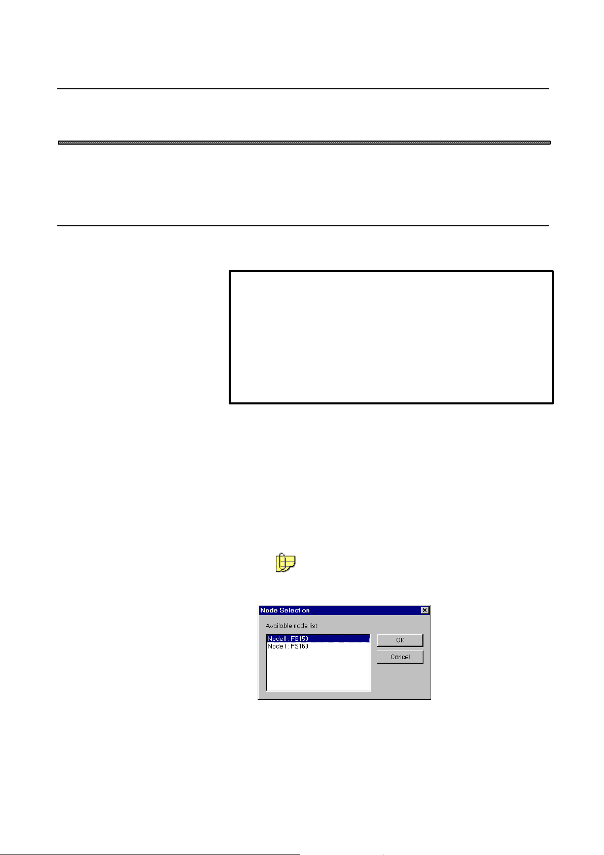
When High Speed Serial Bus multiconnection is being used, the node
selection screen appears if a node number has not been specified for
an argument for Basic Operation Package 1.
For an explanation of how to specify the node number, see
Section 3.2, "Specifying a Node."
4. Select the CNC to be connected.
Click the <OK> button.
-10-
Page 31

B-62994EN/02 2. BASIC KNOWLEDGE
Windows 3.1
1. Start the program from the Basic Operation Package 1 group in the
Program Manager.
The Basic Operation Package 1 screen, shown below, appears.
2.1.2 Terminating Basic Operation Package 1
How to terminate Basic Operation Package 1 is described below.
Procedure
1. If the soft key is currently not displayed, press the function
selection soft key
2. Press the soft key.
If a check mark is not placed against "Enable the language switch
function" in the customization setting, the Basic Operation Package 1
screen disappears and Basic Operation Package 1 is terminated.
If a check mark is placed against "Enable the language switch function"
in the customization setting, the [Exit Basic Operation Package] screen
appears.
.
-11-
Page 32

2. BASIC KNOWLEDGE B-62994EN/02
For details of the language switch function, see Sections
11.1.1, "Setting general options for Basic Operation Package
1," and 11.4.2, "Switching the message language."
3. Select [Exit Basic Operation Package ?].
Click the <Yes> button.
The Basic Operation Package 1 screen disappears and Basic Operation
Package 1 is terminated.
If [Switch language after restart?] is selected, clicking the <Yes> button
restarts Basic Operation Package 1 using the selected language.
-12-
Page 33

B-62994EN/02 2. BASIC KNOWLEDGE
2.2 Window Names and Functions
This section describes the name and functions of each window displayed by
Basic Operation Package 1.
Basic Operation Package 1 displays a parent window which consists of one or
more child windows. Each child window contains the display items of a
conventional CNC screen.
Explanation
l Parent window
• Main window of Basic Operation Package 1
• Selecting a soft key at the bottom of the parent window displays the
corresponding child window within the parent window.
• Multiple child windows can be displayed within the parent window.
• The top of the parent window indicates the function name
corresponding to the child window which is currently active and
statuses such as the CNC mode. The displayed statuses and their
meanings are as follows:
-13-
Page 34

2. BASIC KNOWLEDGE B-62994EN/02
FS15
(1) Automatic operation mode selection
Status Meaning
**** Not selected
MDI MDI mode
Tape TAPE mode
Mem MEMORY mode
Edit EDIT mode
Thin TEACH in mode
(2) Manual operation mode selection
Status Meaning
**** Not selected
Ref REFERENCE mode
Inc INCREMENTAL mode
Hndl HANDLE mode
Jog JOG mode
AngJ ANGULAR JOG mode
IHnd INCREMENTAL + HANDLE mode
JHnd JOG + HANDLE mode
(3) Automatic operation status
Status Meaning
Stop Stopped
Hold Halted
Strt Starting
MStr Numeric JOG mode
Rstr Restarting a block
PRsr Restarting a program
NSrc Searching for a sequence number
Rset Resetting
HPCC RISC operation
(4) Program editing status
Status Meaning
**** No editing
Edit Editing
Srch Searching
Vrfy Verifying
Cond Condensing
Read Inputting data
Pnch Outputting data
-14-
Page 35

B-62994EN/02 2. BASIC KNOWLEDGE
(5) Axial movement and dwell status
Status Meaning
**** Others
Motn Moving along an axis
Dwel Dwelling
Wait Waiting (only for 2-path lathe systems)
(6) M, S, T, and B function status
Status Meaning
Fin Waiting for processing
(7) Emergency stop status
Status Meaning
Emg Emergency stop
(8) Nonvolatile memory write status
Status Meaning
**** No write
Writ Writing
(9) Label skip status
Status Meaning
**** Label skip disabled
LSk Label skip enabled
(10) Alarm status
Status Meaning
Alam Alarm issued
(11) Warning message status
Status Meaning
Warn Warning issued
(12) Battery status
Status Meaning
Batt Battery of nonvolatile memory and absolute position
detector requires replacement
-15-
Page 36

2. BASIC KNOWLEDGE B-62994EN/02
FS160/180/210 or NC Board
(1) Automatic/manual mode selection
Status Meaning
**** Not selected
MDI MDI mode
Mem MEMORY mode
Edit EDIT mode
Hndl HANDLE mode
Jog JOG mode
TJog TEACH in JOG mode
THnd TEACH in HANDLE mode
Inc INCREMENTAL mode
Ref REFERENCE mode
Rmot SCHEDULE mode
Test TEST operation mode
(2) Automatic operation mode
Status Meaning
**** Resetting
Stop Stopped
Hold Halted
Strt Starting
MStr Returning (tool retract and return), repositioning, or
operating based on a manual numeric command
-16-
Page 37

B-62994EN/02 2. BASIC KNOWLEDGE
(3) Program editing status
Status Meaning
***** No editing
Edit Editing
Search Searching
Output Outputting data
Input Inputting data
Compare Comparing
LblSkp Label skip enabled
Restrt Restarting a program
PTRR Tool retract and return mode
HPCC RISC operation (only for machining center systems)
Revers Reverse movement during retrace (only for machining
center systems)
Retry Re-forward movement during retrace (only for
machining center systems)
RvEnd Reverse movement completed during retrace (only for
machining center systems)
Handle Handle interruption applied (only for machining center
systems)
WrkOfs Workpiece origin offset measurement mode (only for
machining center systems)
SHPCC Simple high-precision contour control applied (only for
machining center systems)
WrkSft Work shift write mode (only for lathe systems)
Offset Tool length offset measurement mode (for machining
center systems)/Tool length offset write mode (for lathe
systems)
(4) Axial movement and dwell status
Status Meaning
**** Others
Motn Moving along an axis
Dwel Dwelling
(5) M, S, T, and B function status
Status Meaning
Fin Waiting for processing
-17-
Page 38

2. BASIC KNOWLEDGE B-62994EN/02
(6) Emergency stop status
Status Meaning
Emg Emergency stop
Rset Reset
(7) Alarm status
Status Meaning
Alam Alarm issued
Batt Battery of nonvolatile memory and absolute position
detector requires replacement
For details of each status, refer to the operator's manual provided with
the CNC being used.
l Child window
• Window which implements the display items of an individual CNC screen
• Chapter and function
A collection of child windows is called a chapter.
A collection of chapters is called a function.
Basic Operation Package 1 is configured with the function and chapter
hierarchy shown below.
Functions and chapters can be selected using the soft keys at the
bottom of the parent window.
-18-
Page 39

B-62994EN/02 2. BASIC KNOWLEDGE
l Soft key
• Key-like field used to display a child window. A soft key can be
selected either by clicking the image on the screen or pressing the
corresponding key on the keyboard.
In the standard state, where no soft key customization has been
performed, the soft keys are assigned to the following keyboard keys.
The subsequent descriptions in this manual assume the standard soft
key assignment.
NOTE
The soft keys can be customized. For details, see Section 11.1.2,
"Setting soft keys."
• There are the following three types of soft key states: "Function
selection," "chapter selection," and "operation selection."
For example, the soft keys used for [Position] are switched as follows:
-19-
Page 40

2. BASIC KNOWLEDGE B-62994EN/02
• Function selection state
• Chapter selection state
• Operation selection state
The displayed soft keys are for the currently active child window.
Soft key
or
[F1] key
Soft key
or
[F1] key
Soft key
or
[F12] key
Soft key
or
[F1] key
Soft key
or
[F12] key
Soft key
or
[F12] key
NOTE
l The subsequent descriptions in this manual refer to the selection of a
soft key as simply "pressing a soft key," meaning either clicking the
soft key image on the screen or pressing the corresponding key on
the keyboard.
-20-
Page 41

B-62994EN/02 2. BASIC KNOWLEDGE
2.3 Selecting and Positioning Windows
This section describes how to select and position child windows.
NOTE
Settings may have been made so that the position and size of a
window cannot be changed. For details, see Section 11.1.1, "Setting
general options for Basic Operation Package 1."
2.3.1 Selecting a window
A child window can be selected using the mouse or keyboard.
Procedure
1. Click the window to be selected.
Alternatively, hold down the [Alt] key and press the key corresponding
to the number of the child window (indicated on the title bar).
-21-
Page 42

2. BASIC KNOWLEDGE B-62994EN/02
2.3.2 Positioning a window
The size and position of a child window can be changed as required, using the
mouse or automatic positioning function.
The changed screen display information is stored even when Basic Operation
Package 1 is terminated.
(The changed screen display information is stored in the setting file
upon the termination of Basic Operation Package 1. For details of the setting
file, see Appendix 2, "BACKING UP THE SETTING FILE.")
NOTE
l A child window can be moved only within the parent window.
l Some child windows automatically change their display format
according to the vertical/horizontal ratio of the window.
l Positioning a child window using the mouse
Dragging the title bar or an edge of a child window enables the position and
size of the child window to be changed as required.
l Positioning child windows using the automatic positioning function
This function automatically positions the child windows so that they fit in
the parent window.
-22-
Page 43

B-62994EN/02 2. BASIC KNOWLEDGE
Procedure
Vertically aligning the child windows
1. Right-click the soft key area.
Alternatively, press the [Application] key on the keyboard (such as
the Microsoft Natural keyboard or 109 keyboard).
Alternatively, press [Shift]+[F10].
The following pop-up menu appears:
2. In this case, choose [Tile Vertical].
The child windows are automatically positioned within the parent
window.
-23-
Page 44

2. BASIC KNOWLEDGE B-62994EN/02
2.4 Selecting a Path
If the CNC has multiple paths, select the path to be used as described below.
NOTE
The selection of a path is supported only by TT and MM CNCs and
CNCs having a loader.
Procedure
1. If the
selection soft key
2. Press the
The [Path Setting] screen appears.
3. Select the path to be used for operation.
Click the <OK> button.
soft key is currently not displayed, press the function
.
soft key.
-24-
Page 45

B-62994EN/02 2. BASIC KNOWLEDGE
2.5 Displaying Version Information
This section describes how to display the version information for Basic
Operation Package 1, for maintenance and other purposes.
Procedure
1. Right-click the soft key area.
Alternatively, press the [Application] key on the keyboard (such as the
Microsoft Natural keyboard or 109 keyboard).
Alternatively, press [Shift]+[F10].
The following pop-up menu appears:
2. Choose [About Basic Operation Package...].
The [About Basic Operation Package] screen appears.
The following information is displayed:
• Version information for Basic Operation Package 1
• CNC type ("99" for the NC Board)
• CNC software series
• CNC software version
• Number of controlled axes
-25-
Page 46

3. SETTING THE PARAMETERS REQUIRED TO USE BASIC OPERATION PACKAGE 1 B-62994EN/02
3 SETTING THE PARAMETERS REQUIRED
TO USE BASIC OPERATION PACKAGE 1
This chapter describes how to set the parameters required to display the
screens of Basic Operation Package 1.
-26-
Page 47

B-62994EN/02 3. SETTING THE PARAMETERS REQUIRED TO USE BASIC OPERATION PACKAGE 1
3.1 Setting the CNC Parameters
This section describes how to set the CNC parameters required to use Basic
Operation Package 1.
NOTE
If the CNC parameters are not set, screen display and the writing of
programs and MDI commands cannot be performed normally.
NOTE
To set the parameters, first establish the following status:
l Setting data
• Parameter Write enabled
l Operation
Set either of the following statuses:
• Emergency stop
• Stopped or paused in MDI mode
For an explanation of how to specify the setting data, see Section 6.1,
"Setting Data."
To change the CNC operating mode from the software operator's panel,
see Section 6.7, "Software Operator's Panel Settings."
Procedure
1. If the
selection soft key
2. Press the
soft key is currently not displayed, press the function
.
soft key.
3. If the [Parameter] screen is currently not displayed, press the chapter
selection soft key
.
Press the
soft key.
The [Parameter] screen appears.
-27-
Page 48

3. SETTING THE PARAMETERS REQUIRED TO USE BASIC OPERATION PACKAGE 1 B-62994EN/02
Explanation
Set the following parameters:
l FS15
Description Set value
TV check No. 0000 bit 0 → 0
Foreground input device No. 0020 → 16
Background input device No. 0022 → 16
Enable overwriting of program from outside of NC No. 2200 bit 1 → 1
Use M02 and M30 to terminate registration No. 2200 bit 3 → 1
Enable background editing No. 2201 bit 6 → 1
Use position display No. 2204 bit 1 → 1
Use dynamic data display No. 7613 bit 0 → 1
Use actual speed display No. 7613 bit 1 → 1
Use spindle speed display No. 7613 bit 2 → 1
Use program check No. 7710 bit 7 → 1
The above settings for the foreground input device and background
input device are required to use the program edit screen of Basic
Operation Package 1.
To change the setting of each input device, refer to the FS15
parameter manual.
l FS16/18/21 or NC Board
Description Set value
TV check No. 0000 bit 0 → 0
Enable overwriting of program from outside of NC No. 2200 bit 1 → 1
Use M02, M30, and M99 to terminate registration No. 2200 bit 3 → 1
-28-
Page 49

B-62994EN/02 3. SETTING THE PARAMETERS REQUIRED TO USE BASIC OPERATION PACKAGE 1
3.2 Specifying a Node
This section describes how to specify a node number for Basic Operation
Package 1.
NOTE
A node can be specified only when the WIN32 version is used with
High Speed Serial Bus multiconnection.
Explanation
A node number can be specified as an argument for Basic Operation
Package 1. The format is as follows:
WINBOP32.EXE /NODE=<node-number>
As a node number, specify the number which was set during the installation
of the High Speed Serial Bus driver.
-29-
Page 50

4. POSITION DISPLAY B-62994EN/02
4 POSITION DISPLAY
This chapter describes how to display positions, such as the current position.
-30-
Page 51

B-62994EN/02 4. POSITION DISPLAY
4.1 Overall Position Display
This section describes how to display the overall position display (including
the relative position, absolute position, machine position, and distance to go)
for the program that is currently being executed.
Procedure
1. If the
selection soft key
2. Press the soft key.
3. If the [Over All Position] screen is currently not displayed, press the
chapter selection soft key
Press the
The [Over All Position] screen appears.
soft key is currently not displayed, press the function
.
.
soft key.
-31-
Page 52

4. POSITION DISPLAY B-62994EN/02
Explanation
l Overall position display
The overall position display includes the relative position, absolute
position, machine position, and distance to go for the program that is
currently being executed.
To perform operation such as setting the origin for the relative
coordinates, press the operation selection key
.
The operation soft keys appear.
For details of each function, see the following sections:
Origin Relative Position: Section 4.2.1, "Resetting relative coordinates"
Preset Relative Position: Section 4.2.2, "Presetting relative coordinates"
Set Float Point: Section 4.2.3, "Setting the machine position
to the floating reference position"
Preset Work Coord.: Section 4.2.4, "Presetting the workpiece
coordinate system"
NOTE
When a child window other than the overall position child window
is selected, the operation soft keys do not appear.
For floating reference position setting, a CNC option is required.
When the FS16/18/21 or NC Board is used, a CNC option is
required for workpiece coordinate system presetting.
l Modal screen
Displays modal information about the program that is currently being
executed, such as G codes. No operation can be performed on this
screen.
l Actual speed screen
Displays the feedrate for the program that is currently being executed.
No operation can be performed on this screen.
-32-
Page 53

B-62994EN/02 4. POSITION DISPLAY
4.2 Displaying the Relative Position
This section describes how to display the relative position for the program
that is currently being executed.
Procedure
1. If the
selection soft key
2. Press the soft key.
3. If the [Relative Position] screen is currently not displayed, press the
chapter selection soft key
Press the
The [Relative Position] screen appears.
soft key is currently not displayed, press the function
.
.
soft key.
-33-
Page 54

4. POSITION DISPLAY B-62994EN/02
Explanation
l Relative position screen
Displays the relative position for the program that is currently being
executed.
To perform an operation such as setting the origin for the relative
coordinates, press the operation selection key
.
The operation soft keys appear.
For details of each function, see the following sections:
Origin Relative Position: Section 4.2.1, "Resetting relative coordinates"
Preset Relative Position: Section 4.2.2, "Presetting relative coordinates"
Set Float Point: Section 4.2.3, "Setting the machine position
to the floating reference position"
Preset Work Coord.: Section 4.2.4, "Presetting the workpiece
coordinate system"
NOTE
When a child window other than the overall position child window
is selected, the operation soft keys do not appear.
For floating reference position setting, a CNC option is required.
When the FS16/18/21 or NC Board is used, a CNC option is
required for workpiece coordinate system presetting.
When the Power Mate is used, floating reference position setting
and workpiece coordinate system presetting cannot be
performed.
l Actual speed screen
Displays the feedrate for the program that is currently being executed.
No operation can be performed on this screen.
-34-
Page 55

B-62994EN/02 4. POSITION DISPLAY
4.2.1 Resetting relative coordinates
The coordinates of the relative position can be reset to 0.
Procedure
1. If the [Relative Position] screen (or [Over All Position] screen) is
currently not displayed, display the [Relative Position] screen (or [Over
All Position] screen) by applying the procedure explained in Section
4.2, "Displaying the Relative Position" (or Section 4.1, " Overall
Position Display").
(Example with the [Relative Position] screen)
2. Press the
The [Position - Origin Relative Position] screen appears.
soft key.
-35-
Page 56

4. POSITION DISPLAY B-62994EN/02
3. From the list of the coordinate axes, select one or more axes for which
the relative coordinates are to be reset.
To select all the axes, click the <Set All> button.
To deselect all the axes, click the <Clear All> button.
4. Clicking the <OK> button resets the selected relative coordinates to 0.
4.2.2 Presetting relative coordinates
The coordinates of the relative position can be preset to an entered value.
Procedure
1. If the [Relative Position] screen (or [Over All Position] screen) is
currently not displayed, display the [Relative Position] screen (or [Over
All Position] screen) by applying the procedure explained in Section
4.2, "Displaying the Relative Position" (or Section 4.1, " Overall
Position Display").
-36-
Page 57

B-62994EN/02 4. POSITION DISPLAY
(Example with the [Relative Position] screen)
2. Press the
soft key.
The [Position - Preset Relative Position] screen appears.
3. Select the axis for which the relative coordinate is to be preset.
Enter the value to which the relative coordinate is to be preset.
4. Clicking the <OK> button presets the selected relative coordinate.
-37-
Page 58

4. POSITION DISPLAY B-62994EN/02
4.2.3 Setting the machine position to the floating reference position
The machine position can be set to the floating reference position.
NOTE
To set the floating reference position, the corresponding CNC option is
required.
Procedure
1. If the [Relative Position] screen (or [Over All Position] screen) is
currently not displayed, display the [Relative Position] screen (or [Over
All Position] screen) by applying the procedure explained in Section
4.2, "Displaying the Relative Position" (or Section 4.1, "Overall
Position Display").
(Example with the [Relative Position] screen)
2. Press the
The [Position - Floating Reference Point] screen appears.
-38-
soft key.
Page 59

B-62994EN/02 4. POSITION DISPLAY
3. Select one or more axes for which the machine position is to be set to
the floating reference position.
To select all the axes, click the <Set All> button.
To deselect all the axes, click the <Clear All> button.
Clicking the <OK> button sets the machine position to the floating
reference position.
The set values can be checked by referencing parameter No. 1244.
4.2.4 Presetting the workpiece coordinate system
The workpiece coordinate system can be preset.
The absolute coordinate on the preset axis is set as follows:
Absolute coordinate value = current absolute coordinate value - the value
on the corresponding axis for workpiece origin offset number 0
NOTE
To preset the workpiece coordinate system for the FS160/180/210 or
NC Board, the corresponding CNC option is required.
The workpiece coordinate system cannot be preset for the Power
Mate.
Procedure
1. If the [Over All Position] screen (or [Relative Position] screen) is
currently not displayed, display the [Over All Position] screen (or
[Relative Position] screen) by applying the procedure explained in
Section 4.1, "Overall Position Display" (or Section 4.2, "Displaying the
Relative Position").
-39-
Page 60

4. POSITION DISPLAY B-62994EN/02
(Example with the [Over All Position] screen)
2. Press the soft key.
The [Position - Preset Work Coordinate] screen appears.
3. Select one or more axes for which the workpiece coordinate system is to
be preset.
To select all the axes, click the <Set All> button.
To deselect all the axes, click the <Clear All> button.
Clicking the <OK> button presets the workpiece coordinate system.
-40-
Page 61

B-62994EN/02 4. POSITION DISPLAY
4. Clicking the <OK> button presets the workpiece coordinate system.
-41-
Page 62

4. POSITION DISPLAY B-62994EN/02
4.3 Displaying the Absolute Position
This section describes how to display the absolute position for the program
that is currently being executed.
Procedure
1. If the
selection soft key
2. Press the soft key.
3. If the [Absolute Position] screen is currently not displayed, press the
chapter selection soft key
Press the
The [Absolute Position] screen appears.
soft key is currently not displayed, press the function
.
.
soft key.
Explanation
l Absolute position screen
Displays the absolute position.
To perform an operation such as setting the floating reference position,
press the operation selection key .
-42-
Page 63

B-62994EN/02 4. POSITION DISPLAY
The operation soft keys appear.
For details of each function, see the following sections:
Set Float Point: Section 4.2.3, "Setting the machine position to the
floating reference position"
Preset Work Coord.: Section 4.2.4, "Presetting the workpiece coordinate
system"
l Actual speed screen
Displays the actual cutting feedrate and spindle speed.
No operations can be performed on this screen.
-43-
Page 64

4. POSITION DISPLAY B-62994EN/02
4.4 Displaying the Machine Position
This section describes how to display the machine position for the program
that is currently being executed.
Procedure
1. If the
selection soft key
2. Press the soft key.
3. If the [Machine Position] screen is currently not displayed, press the
chapter selection soft key
Press the
The [Machine Position] screen appears.
soft key is currently not displayed, press the function
.
.
soft key.
Explanation
l Machine position screen
Displays the machine position for the program that is currently being
executed. No operation can be performed on this screen.
l Actual speed screen
Displays the feedrate for the program that is currently being executed.
No operation can be performed on this screen.
-44-
Page 65

B-62994EN/02 4. POSITION DISPLAY
4.5 Displaying the Distance to Go
This section describes how to display the distance to go in the current block
of the program that is currently being executed.
Procedure
1. If the
selection soft key
2. Press the soft key.
3. If the [Distance to Go] screen is currently not displayed, press the
chapter selection soft key
Press the
The [Distance to Go] screen appears.
soft key is currently not displayed, press the function
.
.
soft key.
Explanation
l Distance to Go screen
Displays the distance to go in the current block of the program that is
currently being executed. No operation can be performed on this screen.
l Actual speed screen
Displays the feedrate for the program that is currently being executed.
No operation can be performed on this screen.
-45-
Page 66

4. POSITION DISPLAY B-62994EN/02
4.6 Displaying the Amount of Handle Interruption
This section describes how to display the amount of handle interruption.
NOTE
When the FS15, FS16/18/21, Power Mate-H, or NC Board is used, to
display the amount of handle interruption, the corresponding CNC
option is required.
For an explanation of handle interruption, refer to the manual supplied
by the machine tool builder.
Procedure
1. If the
selection soft key
2. Press the soft key.
3. If the [Handle Interruption] screen is currently not displayed, press the
chapter selection soft key
Press the
The [Handle Interruption] screen appears.
soft key is currently not displayed, press the function
.
.
soft key.
-46-
Page 67

B-62994EN/02 4. POSITION DISPLAY
Explanation
l Handle interruption screen
Displays the amount of handle interruption for the program that is
currently being executed.
To cancel the amount of handle interruption, press the operation
selection soft key
The operation soft keys appear.
For details, see the description below.
l Modal screen
Displays modal information about the program that is currently being
executed, such as G codes. No operation can be performed on this
screen.
l Actual speed screen
Displays the feedrate for the program that is currently being executed.
No operation can be performed on this screen.
.
4.6.1 Canceling the amount of handle interruption
The amount of handle interruption for the specified axis can be canceled.
Procedure
1. If the [Handle Interruption] screen is currently not displayed, display
the [Handle Interruption] screen by applying the procedure explained in
Section 4.6, "Displaying the Amount of Handle Interruption."
-47-
Page 68

4. POSITION DISPLAY B-62994EN/02
2. Press the soft key.
The [Manual Overlap - Cancel Overlap] screen appears.
3. Select one or more axes for which the amount of handle interruption is
to be canceled.
To select all the axes, click the <Set All> button.
To deselect all the axes, click the <Clear All> button.
Clicking the <OK> button cancels the amount of handle interruption for
the specified axes.
-48-
Page 69

B-62994EN/02 4. POSITION DISPLAY
4.7 Displaying the Operating Monitor
This section describes how to display the operating monitor.
NOTE
When the Power Mate is used, the operating monitor screen cannot
be displayed.
Procedure
1. If the
selection soft key
2. Press the soft key.
3. If the [Operating Monitor] screen is currently not displayed, press the
chapter selection soft key
Press the soft key.
The [Operating Monitor] screen appears.
soft key is currently not displayed, press the function
.
.
Explanation
l Operating monitor screen
Displays the load (torque) values for the spindle and servo motors. No
operation can be performed on this screen.
-49-
Page 70

4. POSITION DISPLAY B-62994EN/02
4.8 Displaying the Machining Time and Machined Parts Count
This section describes how to display the machining time and machined parts count.
NOTE
In the standard state, this screen cannot be displayed. Create a
screen containing screen object ID "CutTime" according to the
description in Section 11.2.1, "Creating the custom screens."
To display this screen for the FS16/18/21 or NC Board, the
corresponding CNC option is required.
The [Cut Time and Parts Count] screen is displayed.
Explanation
l Machining time and machined parts count
• Parts count
Displays the number of machined parts.
• Run time
Displays the accumulated operating time during automatic operation
(excluding stopped and paused time).
• Cycle time
Displays the operating time during 1 cycle of automatic operation
(excluding stopped and paused time).
l Operation soft keys
-50-
Page 71

B-62994EN/02 4. POSITION DISPLAY
• Clear Parts Count
Pressing the
soft key clears the parts count to 0.
• Clear Run Time
Pressing the soft key clears the run time to 0.
-51-
Page 72

5. NC PROGRAM B-62994EN/02
5 NC PROGRAM
This chapter explains how to display, edit, and check NC programs stored in
the CNC.
-52-
Page 73

B-62994EN/02 5. NC PROGRAM
5.1 Editing a NC Program
This section explains how to edit a program.
WARNING
l A program in CNC program memory cannot be updated simply by
editing the NC program on the program edit screen of Basic
Operation Package 1. The NC program must be written back to the
CNC after editing.
l After writing an edited NC program back to the CNC, never attempt
to machine a workpiece without first checking the operation of the
machine. Before starting the machine, check that the NC
programmed values, compensation values, current position, and
external signal settings are correct.
NOTE
To edit a program, set the following status:
u Foreground editing (Any NC program can be created, edited, and
deleted.)
FS15
l Operation
• Reset in EDIT mode
l Protect key
• Released
FS16/18/21, Power Mate, or NC Board
l Operation
• Reset in EDIT mode
• P/S alarm 000 (PLEASE TURN OFF POWER) and P/S
alarm 101 (PLEASE CLEAR MEMORY) already released
l Protect key
• Released
u Background editing (A program other than the selected program
can be created, edited, and deleted.)
FS15
l Operation
• Other than EDIT mode
l Protect key
• Released
(to be continued to the next page)
-53-
Page 74

5. NC PROGRAM B-62994EN/02
NOTE (Continued)
u Background editing (A program other than the selected program
can be created, edited, and deleted.)
FS16/18/21 or NC Board
l Operation
• Reset in EDIT mode or MDI mode
• P/S alarm 000 (PLEASE TURN OFF POWER) and P/S
alarm 101 (PLEASE CLEAR MEMORY) already released
l Protect key
• Released
For an explanation of how to release the protect key, refer to the
manual supplied by the machine tool builder.
To change the CNC operating mode from the software operator's
panel, see Section 6.7, "Software Operator's Panel Settings."
Procedure
1. If the soft key is not currently displayed, press the function
selection key
2. Press the
.
soft key.
3. If the [Program Edit] screen is not currently displayed, press the chapter
selection key
Press the
.
soft key.
The [Program Edit] screen appears.
-54-
Page 75

B-62994EN/02 5. NC PROGRAM
Explanation
l Program edit screen
A program can be edited by positioning the cursor to the character string
you want to modify.
Once an edit operation has been performed, "Modified" is displayed in
the upper right part of the child window.
To use a function of, for example, "Get from NC," or "Write Back to
NC," press the operation selection key
.
The operation soft keys appear.
Pressing the displays the operation soft keys on the next page.
For details of each function, see the description below.
-55-
Page 76

5. NC PROGRAM B-62994EN/02
5.1.1 Getting a program from the NC
A program can be read from CNC program memory to the edit screen of
Basic Operation Package 1.
The program currently displayed on the program edit screen is replaced by
the program read from the CNC.
Procedure
1. If the [Program Edit] screen is currently not displayed, display the
[Program Edit] screen by applying the procedure explained in Section
5.1, "Editing a Program."
2. Press the soft key.
The [Program Edit - Get from NC] screen appears.
-56-
Page 77

B-62994EN/02 5. NC PROGRAM
NOTE
When some modifications have been made to the NC
program already displayed on the NC program edit screen, a
prompt appears asking you whether you want to write the NC
program back to the CNC.
To write the NC program back to the CNC, click the <OK>
button. Perform a write operation by following the procedure
explained in Section 5.1.2, "Writing a program back to the NC."
When you don't want to write the NC program back to the CNC,
click the <Cancel> button. Then, the modified NC program is
discarded.
3. Select the NC program you want to get from the NC.
Click the <OK> button.
-57-
Page 78

5. NC PROGRAM B-62994EN/02
5.1.2 Writing a NC program back to the NC
A NC program on the edit screen of Basic Operation Package 1 can be
written back to the CNC.
NOTE
When the FS16/18/21 or NC Board is being used, this function cannot
be used in MDI mode.
Procedure
1. If the [Program Edit] screen is currently not displayed, display the
[Program Edit] screen by applying the procedure explained in Section
5.1, "Editing a NC Program."
2. Press the soft key.
The [Program Edit - Write Back to NC] screen appears.
3. Specify the name of a NC program to be written back to the CNC.
When the NC program to be written is to be executed next, click the
[Save as main] check box.
Click the <OK> button.
-58-
Page 79

B-62994EN/02 5. NC PROGRAM
5.1.3 Inserting a NC program from a disk
A NC program stored on an external memory unit such as a hard disk can be
inserted into the edit screen of Basic Operation Package 1.
The NC program read from the external memory unit is inserted into an
existing NC program displayed on the [Program Edit] screen.
Procedure
1. If the [Program Edit] screen is currently not displayed, display the
[Program Edit] screen by applying the procedure explained in Section
5.1, "Editing a NC Program."
2. Move the cursor to a position at which you want to insert a NC
program.
3. Press the
The [Open] screen appears.
-59-
soft key.
Page 80

5. NC PROGRAM B-62994EN/02
4. Select the NC program to be inserted from the external memory unit.
Click the <Open> button.
The selected file contents are inserted at the cursor position.
5.1.4 Writing a NC program to a disk
A NC program on the edit screen of Basic Operation Package 1 can be
written to an external memory unit such as a hard disk.
Procedure
1. If the [Program Edit] screen is currently not displayed, display the
[Program Edit] screen by applying the procedure explained in Section
5.1, "Editing a NC Program."
-60-
Page 81

B-62994EN/02 5. NC PROGRAM
2. Press the soft key.
The [Save As] screen appears.
3. Enter the name of the NC program to be written to the external memory
unit.
Click the <Save> button.
5.1.5 Finding a character string in a NC program
A search can be made for a specified character string in a NC program.
Procedure
1. If the [Program Edit] screen is currently not displayed, display the
[Program Edit] screen by applying the procedure explained in Section
5.1, "Editing a NC Program."
-61-
Page 82

5. NC PROGRAM B-62994EN/02
2. Press the soft key.
The [Program Edit - Find] screen appears.
3. Enter the character string for which a search is to be made.
Specify the search direction as necessary.
Click the <OK> button.
To search for another character string, repeat steps 2 and 3, above.
5.1.6 Replacing a character string in a NC program
A specified character string in a NC program can be replaced with another
character string.
Procedure
1. If the [Program Edit] screen is currently not displayed, display the
[Program Edit] screen by applying the procedure explained in Section
5.1, "Editing a NC Program."
-62-
Page 83

B-62994EN/02 5. NC PROGRAM
2. Press the soft key.
The [Program Edit - Replace] screen appears.
3. Enter the character string you want to find, and the character string
with which you want to replace that character string.
Specify the search direction as necessary.
Click the <OK> button.
To perform another replacement, repeat steps 2 and 3, above.
5.1.7 Selecting character strings in a NC program
Character strings to be "cut" or "copied" can be selected from a NC program.
Procedure
1. If the [Program Edit] screen is currently not displayed, display the
[Program Edit] screen by applying the procedure explained in Section
5.1, "Editing a NC Program."
-63-
Page 84

5. NC PROGRAM B-62994EN/02
2. Position the cursor to the beginning or end of the character strings to be
selected.
3. Press the
4. Select the character strings by using the direction keys.
soft key.
Cut or copy can be performed by selecting the or
soft key.
Character strings can also be selected by pressing a direction key
while holding down the [Shift] key.
To cancel character string selection mode, press the soft
key again.
5.1.8 Cutting character strings from a NC program
Character strings in a NC program can be cut.
Procedure
1. Select the character strings you want to cut from a NC program.
For an explanation of how to select character strings, see Section 5.1.7,
"Selecting character strings in a NC program."
-64-
Page 85

B-62994EN/02 5. NC PROGRAM
2. Press the soft key.
The selected character strings are cut.
The character strings can also be cut by pressing the [Ctrl]+[X] keys
instead of pressing the
soft key.
The cut character strings can be pasted by pressing the
soft key.
-65-
Page 86

5. NC PROGRAM B-62994EN/02
5.1.9 Copying character strings from a NC program
Character strings in a program can be copied for subsequent pasting.
Procedure
1. Select the character strings you want to copy from the program.
For an explanation of how to select character strings, see Section 5.1.7,
"Selecting character strings in a NC program."
2. Press the soft key.
The selected character strings are copied.
The display remains as is.
The character strings can also be copied by pressing the [Ctrl]+[C]
keys instead of pressing the soft key.
The copied character strings can be pasted by pressing the
soft key.
-66-
Page 87

B-62994EN/02 5. NC PROGRAM
5.1.10 Pasting character strings into a NC program
The cut or copied character strings can be pasted at a specified position.
Procedure
1. Select the character strings you want to paste.
For an explanation of how to select character strings, see Section 5.1.7,
"Selecting character strings in a NC program."
2. Press the soft key.
Or, press the soft key.
In this example,
3. Position the cursor to the point where you want to paste the character
strings.
4. Press the
is pressed.
soft key.
-67-
Page 88

5. NC PROGRAM B-62994EN/02
The character strings can also be pasted by pressing the [Ctrl]+[V]
keys instead of the soft key.
5.1.11 Inserting sequence numbers into a NC program
Sequence numbers can be inserted automatically when a new NC program is
created.
Procedure
1. If the [Program Edit] screen is currently not displayed, display the
[Program Edit] screen by applying the procedure explained in Section
5.1, "Editing a NC Program."
-68-
Page 89

B-62994EN/02 5. NC PROGRAM
2. Press the soft key.
The [Program Edit - Insert Sequence Number] screen appears.
3. Check the [Insert sequence number] check box, and set the initial value
and increment.
Click the <OK> button.
Sequence numbers are automatically inserted as a new NC program is
created.
Automatic insertion of sequence numbers is also enabled by
specifying setting data. For an explanation of how to specify setting
data, see Section 6.1, "Setting Data."
Explanation
The values on the [Program Edit - Insert Sequence Number] screen can
also be set using the following parameters:
-69-
Page 90

5. NC PROGRAM B-62994EN/02
l FS15
Meaning Setting
Enabling automatic insertion No. 0010 bit 1 → 1
Initial value and increment No. 3216
l FS16/18/21 or NC Board
Meaning Setting
Enabling automatic insertion No. 0000 bit 5 → 1
Initial value No. 0031
Increment No. 0032
-70-
Page 91

B-62994EN/02 5. NC PROGRAM
5.1.12 Entering a coordinate value into a NC program
The current absolute coordinate value can be entered into a program.
NOTE
A CNC option (playback) is required to enter a coordinate value into a
program.
Before entering a coordinate value into the program, change from the
operation status explained in Section 5.1, "Editing a NC Program," to
the following CNC operating mode:
• Teach in Handle mode
or
• Teach in JOG mode
When the Power Mate is used, no CNC option is required to enter a
coordinate value into a program. Change the operation status
explained in Section 5.1, "Editing a Program," to the following CNC
operating mode:
• Teach in JOG/Handle mode
Procedure
1. If the [Program Edit] screen is currently not displayed, display the
[Program Edit] screen by applying the procedure explained in Section
5.1, "Editing a NC Program."
-71-
Page 92

5. NC PROGRAM B-62994EN/02
2. Position the cursor to the point where a coordinate value is to be
entered.
3. Press the
The [Program Edit - Teach In] screen appears.
4. Select the axis for which a coordinate value is to be entered.
Click the <OK> button.
soft key.
The absolute coordinate value is inserted into the NC program.
-72-
Page 93

B-62994EN/02 5. NC PROGRAM
5.1.13 Displaying the top of a NC program
The top of a NC program can be displayed.
Procedure
1. If the [Program Edit] screen is currently not displayed, display the
[Program Edit] screen by applying the procedure explained in Section
5.1, "Editing a NC Program."
2. Press the soft key.
The top of the NC program is displayed with the cursor positioned to
the top of the NC program.
-73-
Page 94

5. NC PROGRAM B-62994EN/02
5.1.14 Displaying the end of a NC program
The end of a NC program can be displayed.
Procedure
1. If the [Program Edit] screen is currently not displayed, display the
[Program Edit] screen by applying the procedure explained in Section
5.1, "Editing a NC Program."
2. Press the soft key.
The end of a NC program is displayed with the cursor positioned to the
end of the NC program.
-74-
Page 95

B-62994EN/02 5. NC PROGRAM
5.1.15 Stamping the machining time
The machining time for an executed NC program can be inserted into the NC
program as a comment.
NOTE
When the FS15, FS16/18/21, or NC Board is used, a CNC option is
required for stamping the machining time. When the machining time
is to be stamped for a NC program, the NC program must have been
executed at least once since the CNC was turned on.
When the Power Mate is used, the machining time cannot be
stamped.
Procedure
1. If the [Program Edit] screen is currently not displayed, display the
[Program Edit] screen by applying the procedure explained in Section
5.1, "Editing a NC Program."
2. Press the soft key.
When the NC program has already been executed, the machining time
is stamped.
-75-
Page 96

5. NC PROGRAM B-62994EN/02
If the NC program has not yet been executed, the following message
appears:
-76-
Page 97

B-62994EN/02 5. NC PROGRAM
5.2 Editing an MDI Program
This section explains how to edit an MDI program.
WARNING
After editing an MDI program, never attempt to machine a workpiece
without first checking the operation of the machine. Before starting
the machine, check that the programmed values, compensation
values, current position, and external signal settings are correct.
NOTE
To edit an MDI program, set the following status:
l Operation
• Stopped or paused in MDI mode
To change the CNC operating mode from the software operator's
panel, see Section 6.7, "Software Operator's Panel Settings."
Procedure
1. If the soft key is currently not displayed, press the function
selection key .
2. Press the
soft key.
3. If the [MDI Program] screen is currently not displayed, press the
chapter selection key
Press the
.
soft key.
The [MDI Program] screen appears.
-77-
Page 98

5. NC PROGRAM B-62994EN/02
Explanation
lMDI program screen
An MDI program can be edited by positioning the cursor to the character
string you wish to edit.
To use a function such as "Find" or "Replace" for a program, press the
operation selection key
The operation soft keys appear.
Pressing displays the operation soft keys on the next page.
For details of each function, see the description below.
-78-
Page 99

B-62994EN/02 5. NC PROGRAM
5.2.1 Finding a character string in an MDI program
A search can be made for a specified character string in an MDI program.
Procedure
1. If the [MDI Program] screen is currently not displayed, display the
[MDI Program] screen by applying the procedure explained in Section
5.2, "Editing an MDI Program."
2. Press the soft key.
The [MDI Program - Find] screen appears.
3. Enter the character string for which a search is to be made.
Specify the search direction as necessary.
Click the <OK> button.
To perform another search operation, repeat steps 2 and 3 above.
-79-
Page 100

5. NC PROGRAM B-62994EN/02
5.2.2 Replacing a character string in an MDI program
A specified character string in an MDI program can be replaced with another,
specified character string.
Procedure
1. If the [MDI Program] screen is currently not displayed, display the
[MDI Program] screen by applying the procedure explained in Section
5.2, "Editing an MDI Program."
2. Press the soft key.
The [MDI Program - Replace] screen appears.
3. Enter the character string you want to find, and the character string
with which you want to replace the found character string.
Specify the search direction as necessary.
Click the <OK> button.
To perform another replacement operation, repeat steps 2 and 3 above.
-80-
 Loading...