

Page 1
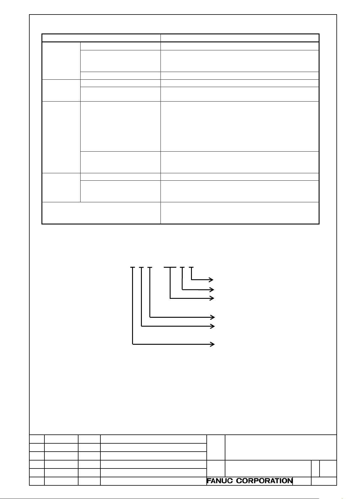
Edit.
Date
Desig.
Description
Page
1 / 18
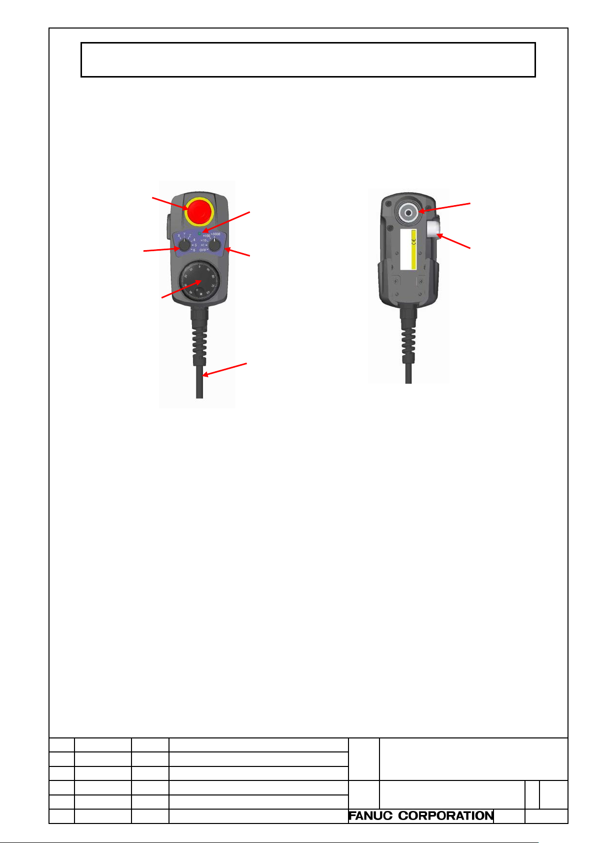
Emergency
switch
Axis
switch
Magnification
switch
Manual
generator
GeneralLED
Enable
switch
Magnet
Cable
PORTABLE MANUAL PULSE GENERATOR SPECIFICATIONS
1. SPECIFICATIONS
1.1 OVERVIEW
The portable manual pulse generator is an I/O device for manual handle feed that is equipped with a
manual pulse generator, emergency stop switch, enable switch, axis selection switch, magnification
selection switch, and LED.
Connect it to a FANUC I/O device, and connect it to a CNC with the I/O Link or I/O Link i.
Main functions
・Emergency stop switch
This is the switch which makes a system in emergency s top state.
・Enable switch
This switch is used to enable manual handle feed.
・Axis selection switch
This switch is used to select t he axi s on which to perform manual handle feed.
・Magnification selection switch
This switch is used to set the travel di st ance per pul se of manual handle f eed, using a magni fic ation of
・Manual pulse generator
This generator outputs pulses for manual handle feed.
・General-purpose LED
This is a LED for general-purpose.
It is turned ON/OFF by connecting it to the DO of a FANUC I/O device.
stop
selection
pulse
purpose
selection
the minimum unit of the travel distance per pulse.
01 Apr.28.2017
Kobayashi
New issue Okita
Title
Draw.
Portable manual pulse generator
specifications
A-45302E
Page 2
Edit.
Date
Desig.
Description
Page
2 / 18
CAUTION
apparatus susceptible to magnetism around the place where the unit is put on.
NOTE
Do not pull the cable strongly.
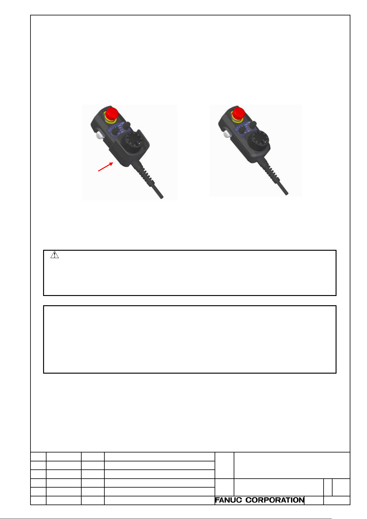
Guard
Portable manual pulse
Portable manual pulse
・Guard
Risk assessment considered the specifications of the machine is conducted by each machine tool
builder, and if there is a risk due to one-hand operation as a result, it is necessary to take a
countermeasure appropriately.
As the following figure shows, this guard builds walls around the rotary knob of manual pulse
generator.
Building walls can be used as a means for leading the operator to operate the manual pulse generator
with both hands.
If the guard is necessary, please select the portable manual pulse generator with guard.
generator with guard
generator without guard
A magnet is mounted at the rear side of the portable manual pulse generator. Watch out people wearing a
・
medical electronics pacemaker for example. If the magnet gets close the medical electronics, the electronics
may have a serious malfunction.
・When you put the portable manual pulse generator on a machine tool by the magnet, check it that there is no
Do not disassemble the portable manual pulse generator.
・
Do not apply to each cable any voltage other than the one stated in the Specific ations.
・
If incorrect routing or connection is made, the device may be damaged or burned.
・
A magnet is mounted at the rear side of this unit. Do not bring any device susceptible to magnetism close to
・
the unit. If you do, the contents stored by its memory are damaged, or, the device is magnetized and it
cannot be used any more.
Be careful not to drop the portable manual pulse generator or give strong impact to it.
・
・
Title
Draw.
Portable manual pulse generator
specifications
A-45302E
Page 3
Edit.
Date
Desig.
Description
Page
3 / 18
Item
Description
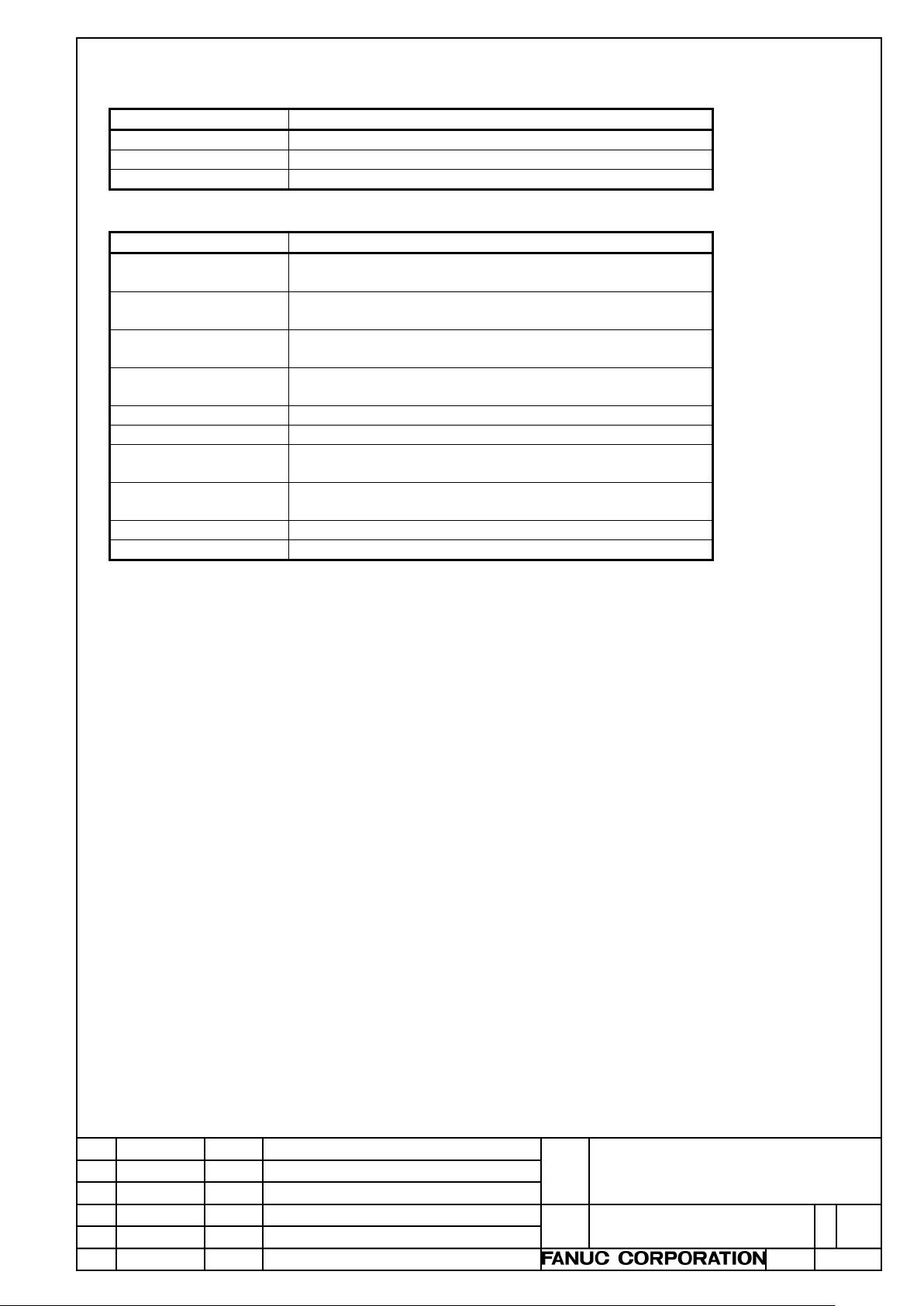
External dimensions
Refer to the next page.
Weight
Refer to the next page.
Protective structure
IP65 compliant
Item
Description
Manual pulse
generator
Phases A and B, phase difference: 90 degrees, 100
pulses/rotation
Axis selection switch
Selectable from 3 contacts (X, Z, and C)
and 6 contacts (X, Y, Z, 4, 5, and 6)
Magnification
selection switch
5 contacts (OFF, x1, x10, x100, and x1000)
Emergency stop
switch
NC, 2 contacts
Enable switch
NO, 3 positions, 2 contacts
General-purpose LED
1 pc. , to be turned ON with the DO of an I/O device.
Cable
24-conductor shielded straight cable,
or coiled cable
Cable length
Straight: selectable from 3.5m and 5.0m
Coiled: 1.0m (coiled part: 0.5m)
Cable end treatment
Connector: round shaped, 24 pins type
Guard
Optional
1.2. DETAILS OF SPECIFICATIONS
Overview
Individual specifications
Title
Draw.
Portable manual pulse generator
specifications
A-45302E
Page 4

Edit.
Date
Desig.
Description
Page
4 / 18
External view and dimensions (without guard)
140.0
210.6
External view and dimensions (with guard)
66.0
66.0
74.1
Unit: mm
77.0
143.2
210.6
Unit: mm
Title
Draw.
Portable manual pulse generator
specifications
A-45302E
Page 5
Edit.
Date
Desig.
Description
Page
5 / 18
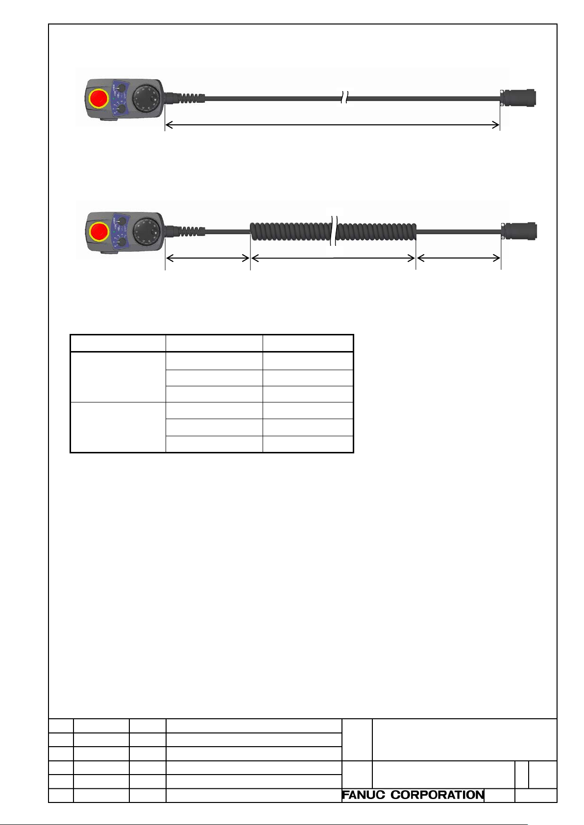
Option type
Cable type
Weight (approx.)
Coiled
810 g
Coiled
860 g
Cable length (straight cable, connector at the end)
Cable length (coiled cable, connector at the end)
3.5m or 5.0m
0.27m
About 0.5m
Weight of the portable manual pulse generator
Without guard Straight, 3.5m 800 g
Straight, 5.0m 1,000 g
With guard Straight, 3.5m 850 g
Straight, 5.0m 1,050 g
0.27m
Title
Draw.
Portable manual pulse generator
specifications
A-45302E
Page 6
Edit.
Date
Desig.
Description
Page
6 / 18
Item
Description
Ambient
Operating
0°C to 45°C
Non-operating (including
transportation)
-20°C to 60°C
Temperature change
0.3°C/minute or less
Humidity
Normal
75%RH or less, no condensation.
Short period (less than 1
month)
95%RH or less, no condensation
Vibration
Operating
4.9m/s2 (0.5G) or less. FANUC's evaluation test was
Number of sweep cycles: 10
Non-operating (including
transportation)
9.8m/s2 (1.0G) or less
Meters
Operating
1,000m or less
Non-operating (including
transportation)
12,000m or less
Environment
Coolant, lubricant, or cutting chips shal l not be
allowed.
1.3. CONDITIONS FOR USE
temperatur
e
storage and
storage and
conducted under the following conditions complying
with IEC 60068-2-6.
10 to 58Hz: 0.075mm (amplitude)
58 to 500Hz: 9.8m/s
2
(1.0G)
Vibration direction: Each of the X, Y, and Z directions
above sea
level
storage and
1.4. ORDERING INFORMATION
The ordering information is as follows:
A13B-0206-C△□○#◇◇☆▽
sprinkled directly over it. No corrosive gas shall be
Cable end (“C”: with connector)
Cable type (“S”: straight, “R”: coiled)
Cable length
(“35”: 3.5m, “50”: 5m, for example)
Number (assigned from “1”)
Assumed machine tool
(“0”: T series, “1”: M series)
Options
(“0”: without Guard, “1”: with Guard)
Title
Draw.
Portable manual pulse generator
specifications
A-45302E
Page 7

Edit.
Date
Desig.
Description
Page
7 / 18
Ordering information
Attach
Axis
switch
Magnification
switch
Cable
Length
Shape
End
treatment
A13B-0206-C001#35SC
No
X, Z, C
OFF, x1, x10,
3.5m
Straight
Connector
A13B-0206-C001#50SC
5.0m
A13B-0206-C001#10RC
1.0m
Coiled
A13B-0206-C011#35SC
X, Y, Z,
3.5m
Straight
A13B-0206-C011#50SC
5.0m
A13B-0206-C011#10RC
1.0m
Coiled
A13B-0206-C101#35SC
Yes
X, Z, C
3.5m
Straight
A13B-0206-C101#50SC
5.0m
A13B-0206-C101#10RC
1.0m
Coiled
A13B-0206-C111#35SC
X, Y, Z,
3.5m
Straight
A13B-0206-C111#50SC
5.0m
A13B-0206-C111#10RC
1.0m
Coiled
Name
Ordering
information
Remarks
for machine tool side
Specifications list
-ment
selection
selection
x100, x1000
4, 5, 6
4, 5, 6
When the portable manual pulse generator is installed on a machi ne, it is necessary t o order the following
item:
Connector
A13B-0206-K001 Hirose Electric Co., Ltd., JR25WR-24S(71)
Title
Draw.
Portable manual pulse generator
specifications
A-45302E
Page 8
Edit.
Date
Desig.
Description
Page
8 / 18
CAUTION
blowout, malfunctions, etc.
NOTE
Connect the cable shield (Pin# 15) to the ground on the machine side.
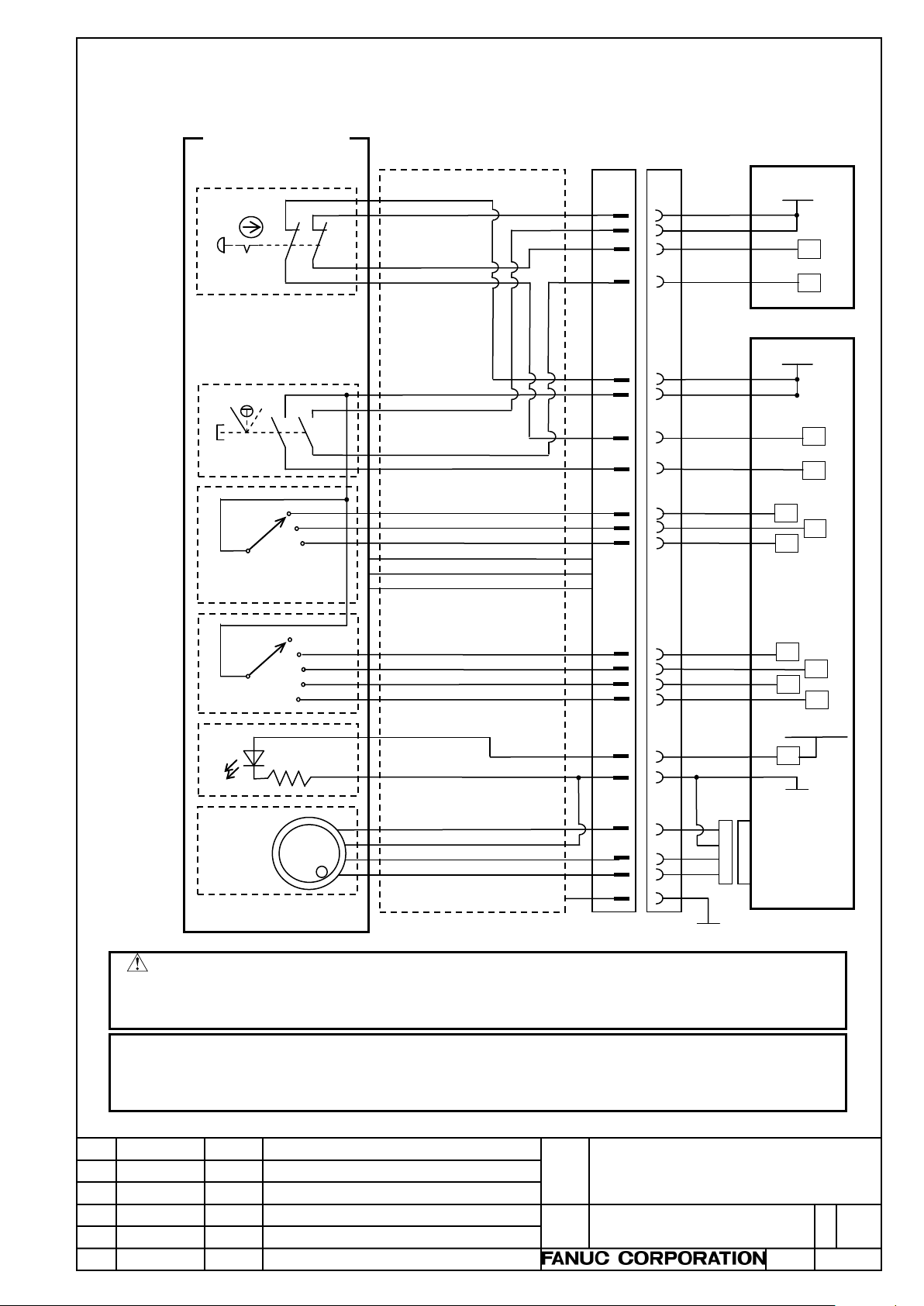
Connection example for the T series (axis selection switch: X, Z, and C)
Axis
Emergency
switch
MagnifiGeneral-
Enable
switch
+24V1
+24V2
+5V
0V
HA
HB
ESPCOM1
ESPCOM2
ESP2
ESP1
EN2
EN1
X Z C
OFF
x1
x10
x100
x1000
LED+
LED-
Manual
RV
RV
RV
RV
RV
RV
RV
RV
DV
0V
JA3
24V
24V
0V
DOCOM
Portable manual
DCS PMC side
I/O module
21
RV
PMC side I/O module
Signal name
Connector
Pin# (NOTE)
RV
RV
11 2 13
17
16 7 12
19
18
23 4 9 3 8
14
6
1
5
10
(Shield of cable)
15
2. CONNECTION
2.1 OVERVIEW
pulse generator
stop
selection
switch
cation
selection
switch
purpose
LED
pulse
generator
If not using +24V for DI that is output fr om a FANUC I/O device, be sure to mount a fuse (with a capacity of 1A
or less). Otherwise, if a fault such as a ground fault occurs on the path, this can cause fire, breakdown,
For information about Pin number, see Section 2.9.
The cable of the portable manual pulse generator is s hi elded.
Title
Draw.
Portable manual pulse generator
specifications
A-45302E
Page 9
Edit.
Date
Desig.
Description
Page
9 / 18
blowout, malfunctions, etc.
Connect the cable shield (Pin# 15) to the ground on the machine side.
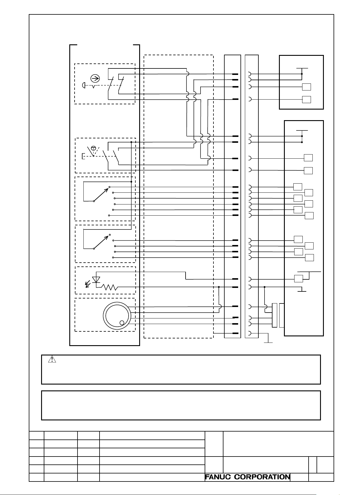
Connection example for the M series (axis selection switch: X, Y, Z, 4, 5, and 6)
+24V1
+24V2
+5V
0V
HA
HB
ESPCOM1
ESPCOM2
ESP2
ESP1
EN2
EN1
X Y Z
OFF
x1
x10
x100
x1000
LED+
LED-
RV
RV
RV
RV
RV
RV
RV
RV
DV
0V
JA3
24V
24V
DOCOM
21
RV
RV
RV
11 2 13
17
16 7 12
19
18
23 4 9
3
8
14
6 1 5
10
RV
RV
RV 4 5 6 20
24
22
0V
(Shield of cable)
15
Axis
Emergency
switch
MagnifiGeneral-
Enable
switch
Manual
Portable manual
DCS PMC side
I/O module
PMC side I/O module
Signal name
Connector
Pin# (NOTE)
pulse generator
stop
selection
switch
cation
selection
switch
purpose
LED
pulse
generator
CAUTION
If not using +24V for DI that is output fr om a FANUC I/O device, be sure to mount a fuse (with a capacity of 1A
or less). Otherwise, if a fault such as a ground fault occurs on the path, this can cause fire, breakdown,
NOTE
For information about Pin number, see Section 2.9.
The cable of the portable manual pulse generator is shielded.
Title
Draw.
Portable manual pulse generator
specifications
A-45302E
Page 10
Edit.
Date
Desig.
Description
Page
10 / 18
Condition
Specifications
Contacts
NC, 2 contacts
Insulating resistance
100MΩ or greater
Maximum voltage
30V (DC)
Maximum current
10mA
CAUTION
malfunctions, etc.
Condition
Specifications
Contacts
NO, 3 positions, 2 contacts
Maximum voltage
30V (DC)
Maximum current
10mA
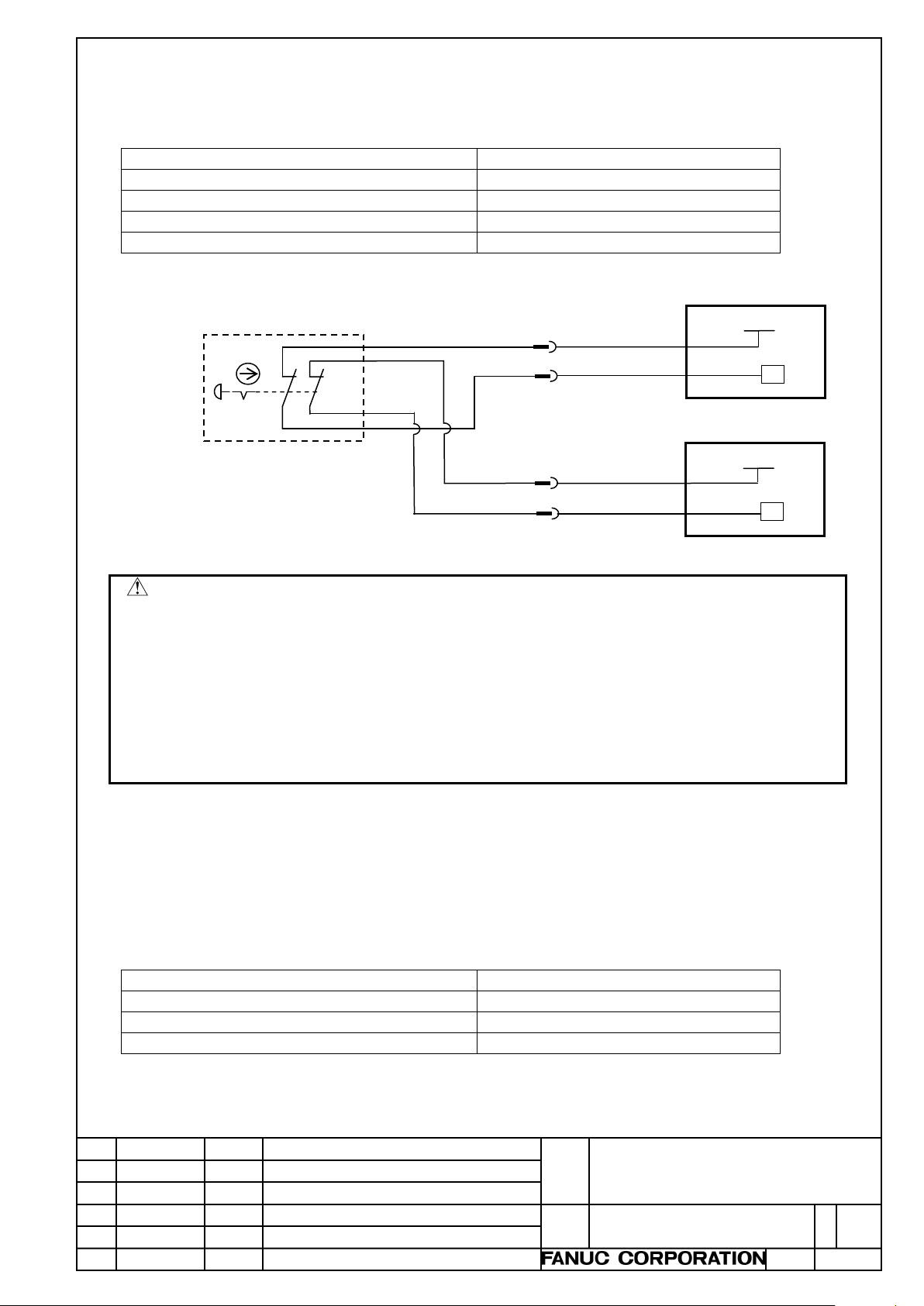
PMC side
I/O module
Emergency
stop switch
ESPCOM1
ESPCOM2
ESP2
ESP1
RV
24V
RV
24V
DCS PMC side
I/O module
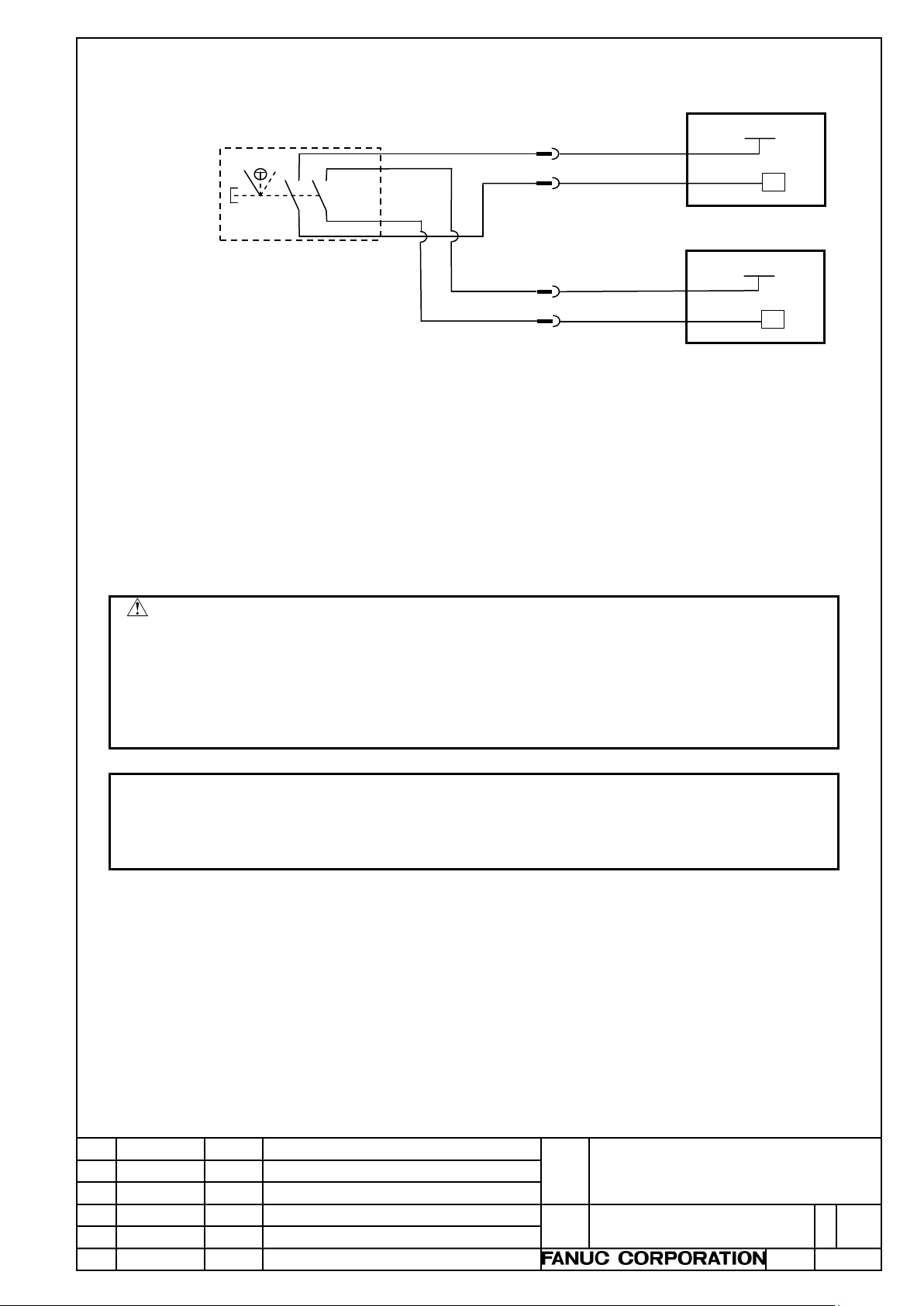
2
2.2 EMERGENCY STOP SWITCH
To detect contact failures, the em ergency stop switch has two contacts.
For safety reasons, use the two contact s to detect mismatches.
Connect the emergency stop signal (ESP1, ESP2) to the safety circ ui t for the entire machine.
17
7
21
1 Periodically check that the emergency stop switch functions normally.
2 When using the portable manual pulse generator, make sure that the CNC and the servo amplifier can be
brought to an emergency stop, using the emergency stop switch of the portable manual pulse generator.
3 If using the portable manual pulse generator with a detachable connection, remov e the portable manual pulse
generator from the connection panel when not operating it, and store it in a loc ation where it cannot be
operated. (This is required to prevent other people f rom misunderstanding that the emergency stop switch on
the portable manual pulse generator is effective.)
4 At the uppermost stream of the emergency stop line, be sure to mount a fuse (with a capacity of 1A or less).
Otherwise, if a fault such as a ground fault occurs on the path, this can cause fire, breakdown, blowout,
2.3 ENABLE SWITCH
To detect contact failures, the enabl e switch has two contacts.
For safety reasons, use the two contacts to detect mismatches.
This switch has three positions, OFF, ON, and OFF. For use, it must be hel d in a hand. When kept in
the intermediate position, the switch is in t he ON (contact closed) state. If the operator faces danger, f or
example, and releases the switch from his or her hand or, conversely, holds it tight, the switch is placed
in the OFF (contact open) state.
Title
Draw.
Portable manual pulse generator
specifications
A-45302E
Page 11
Edit.
Date
Desig.
Description
Page
11 / 18
CAUTION
PMC side
I/O module
DCS PMC side
I/O module
+24V1
+24V2
EN2
EN1
RV
24V
RV
Enable
switch
24V
13
16
12
11
When operating the enable switch, hold it tight until it reaches the intermediate position.
The enable switch inc orporates two independent contacts . Becaus e of the st ructure, a mismatch may
occur between the two contacts if operations such as the following are performed: Keeping the
switch before the intermediate position; and hol ding the switch slowly.
The force required to hold the enable switch to the intermediate posit ion is about 3N, and the force
required to hold it beyond the intermediate position is about 12N. When the enable switch is
operated, it is not necessary to search for the intermediate position.
If, during machine operation, the enable switch is held strongly, first release the enable switch for
safety reasons and then restart the operation.
1 If the operator may face danger when operating the machine with the portable manual pulse generator, be
sure to configure a safety circuit so that the machine can be plac ed i n the interlock state, using the enable
switch on the portable manual pulse generator.
2 Before performing any operations that may cause the operator to f ace danger, such as opening the protective
cover and entering inside the safety fence, the operator m ust check that the enable switch functions normally
in a state in which he or she is safe.
NOTE
1 The safety standard may differ from one machine to another. Chec k the relevant safety standard.
Using Dual Check Safety (DCS) function in a system, the enable switch in the portable manual pulse
generator is complied with Category 3 PL d.
Title
Draw.
Portable manual pulse generator
specifications
A-45302E
Page 12
Edit.
Date
Desig.
Description
Page
12 / 18
Condition
Specifications
Contacts
3 or 6
Maximum voltage
30V (DC)
Maximum current
10mA
NOTE
(see p.18).
Axis
(3 contacts)
Axis
(6 contacts)
To be connected to
+24V for DI
To be connected
to DI of I/O device
To be connected to
+24V for DI device
To be connected
to DI of I/O device
Axis selection switch,
Axis selection switch,
X Z C
+24V1
X
Y
Z
4
5
6
+24V1
19
23
19
23
22
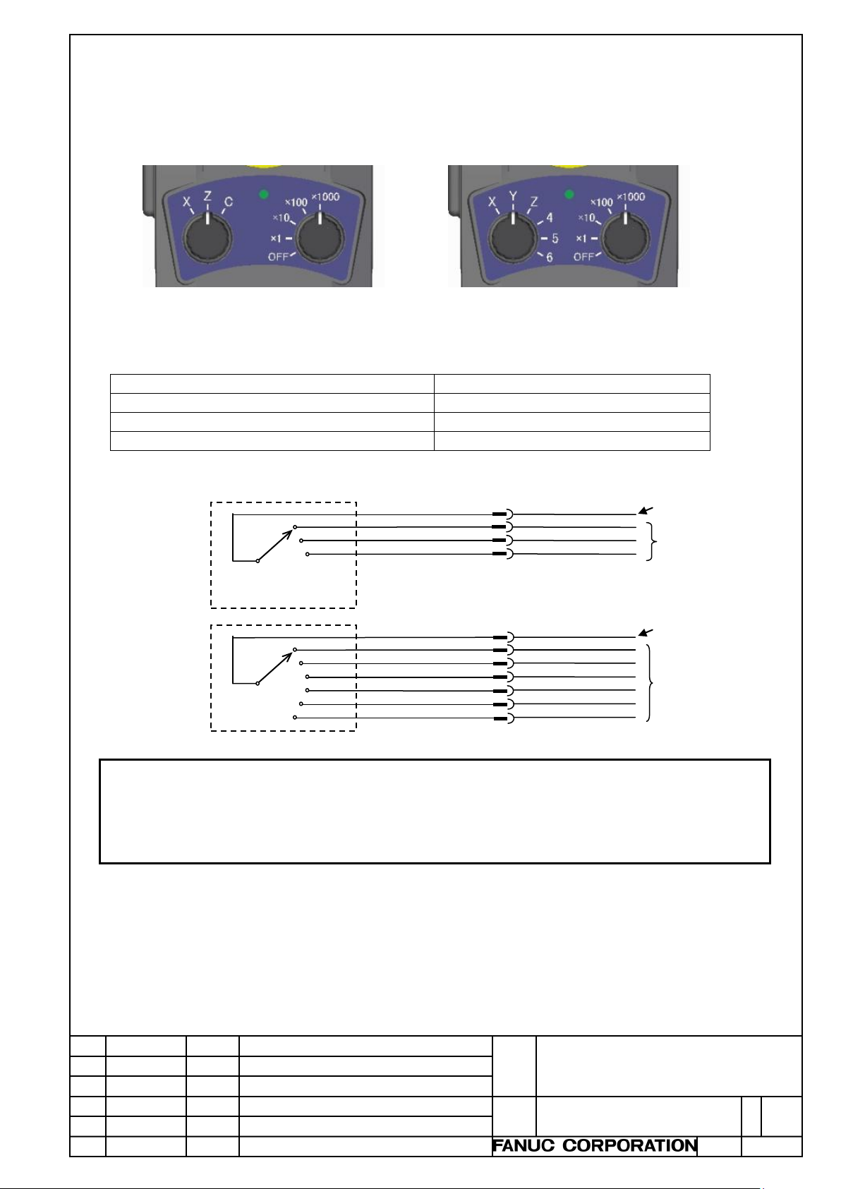
2.4 AXIS SELECTION SWITCH
This switch is used to select the axi s on which to perform manual handle feed.
The switch is available in two types, one for the T series (3 contacts X, Z, and C) and the other for the
M series (6 contacts X, Y, Z, 4, 5, and 6). Rotary switches with 3 contacts and 6 contacts are used for
them, respectively.
The contact of the power for DI (+24V1) and the selected axis will be closed (ON).
3 contacts
6 contacts
16
selection
18
switch
16
selection
switch
We have two types of the axis selection switch: with 3 cont ac ts and 6 contacts. Please select the switch in order
・
to the axial composition in a machine tool.
It is only two types that the scale description of the axis selection switch: X, Z and C( for T series) , and X, Y, Z,
・
4, 5 and 6 ( for M series). If you need other description, please make new label sheet following Appendix A
18
20
24
Title
Draw.
Portable manual pulse generator
specifications
A-45302E
Page 13
Edit.
Date
Desig.
Description
Page
13 / 18
Condition
Specifications
Contacts
5
Maximum voltage
30V (DC)
Maximum current
10mA
need other description, please make new label sheet following Appendix A (see p.18).
Condition
Specifications
Maximum voltage
30V (DC)
(absolute maximum rating)
LED forward current
(absolute maximum rating)
25mA
(absolute maximum rating)
Resistance
5.6kΩ
Magnification
selection switch
General-purpose
LED
To be connected to
+24V for DI
To be connected
to DI of I/O device
To be connected to
DO of I/O device
To be connected to
0V of I/O device
OFF
x1
x10
x100
x1000
+24V1
16
4
3
8
LED+
LED-
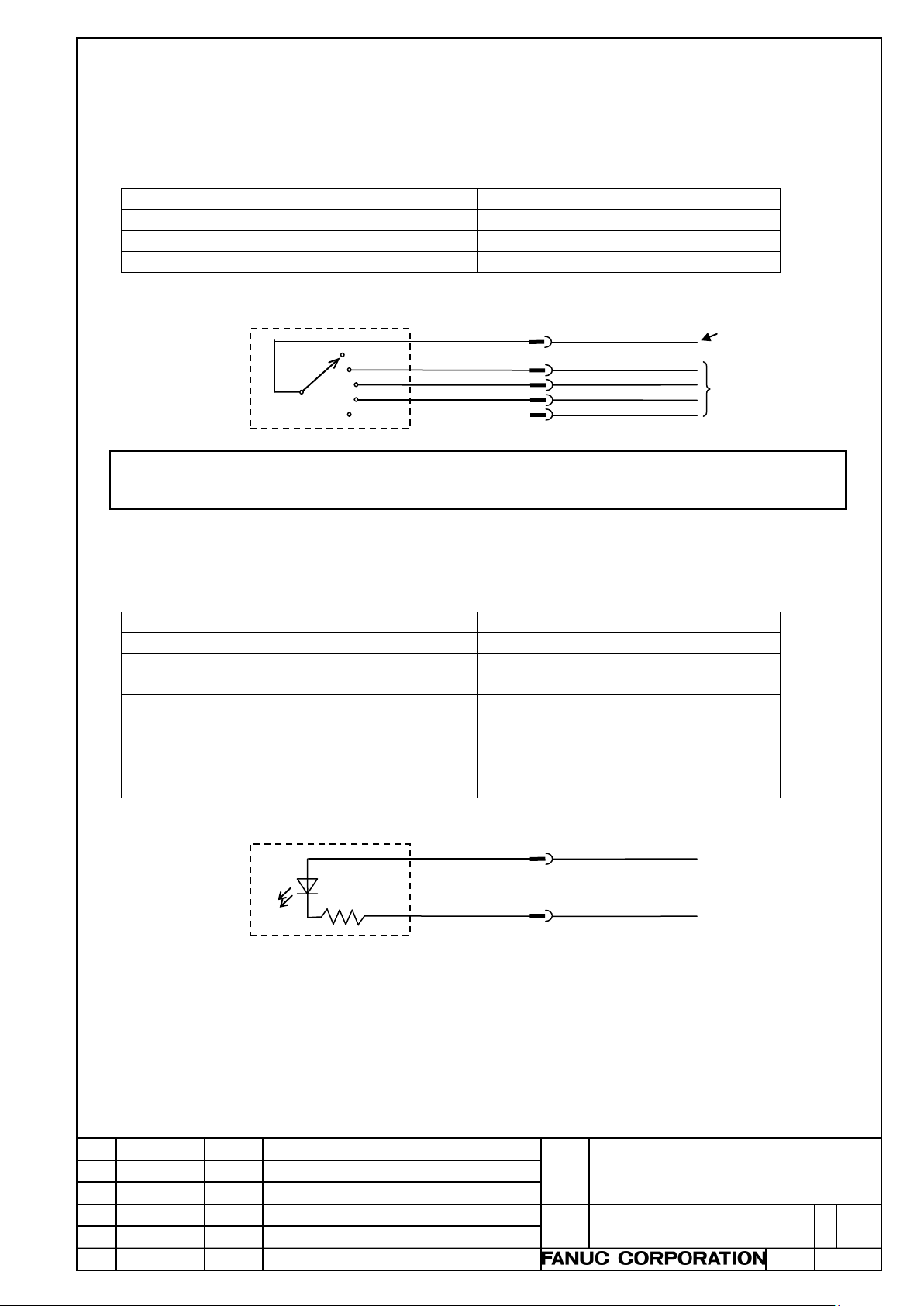
2.5 MAGNIFICATION SELECTION SWITCH
Set the travel distance per pulse of manual handle feed, using a magnification of the least input
increment.
This is a switch with 5 contacts (OFF, x1, x10, x100, and x1000).
The contact of the power for DI (+24V1) and the sel ected magnification will be closed (ON).
If OFF is selected, no signal will be output.
9
NOTE
It is only one type that the scale description of the magnificat ion switch: OFF, x1, x10, x100and x1000. If you
・
2.6 GENERAL-PURPOSE LED
The LED can be turned ON/OFF with DO signals.
LED allowable dissipation
Reverse voltage
62mW
5V
14
6
Title
Draw.
Portable manual pulse generator
specifications
A-45302E
Page 14
Edit.
Date
Desig.
Description
Page
14 / 18
routing them.
Manual
generator
To be connected to
1
HA
11 2
HB
12
0V 3
13 4 14
0V 5
15 6 16
0V 7
17 8 18
+5V 9 +5V
19 10 20
+5V
Recommended connector:
Case: Hirose Electric Co., Ltd. FI40-20-CV5)
+5V
0V
HA
HB
6
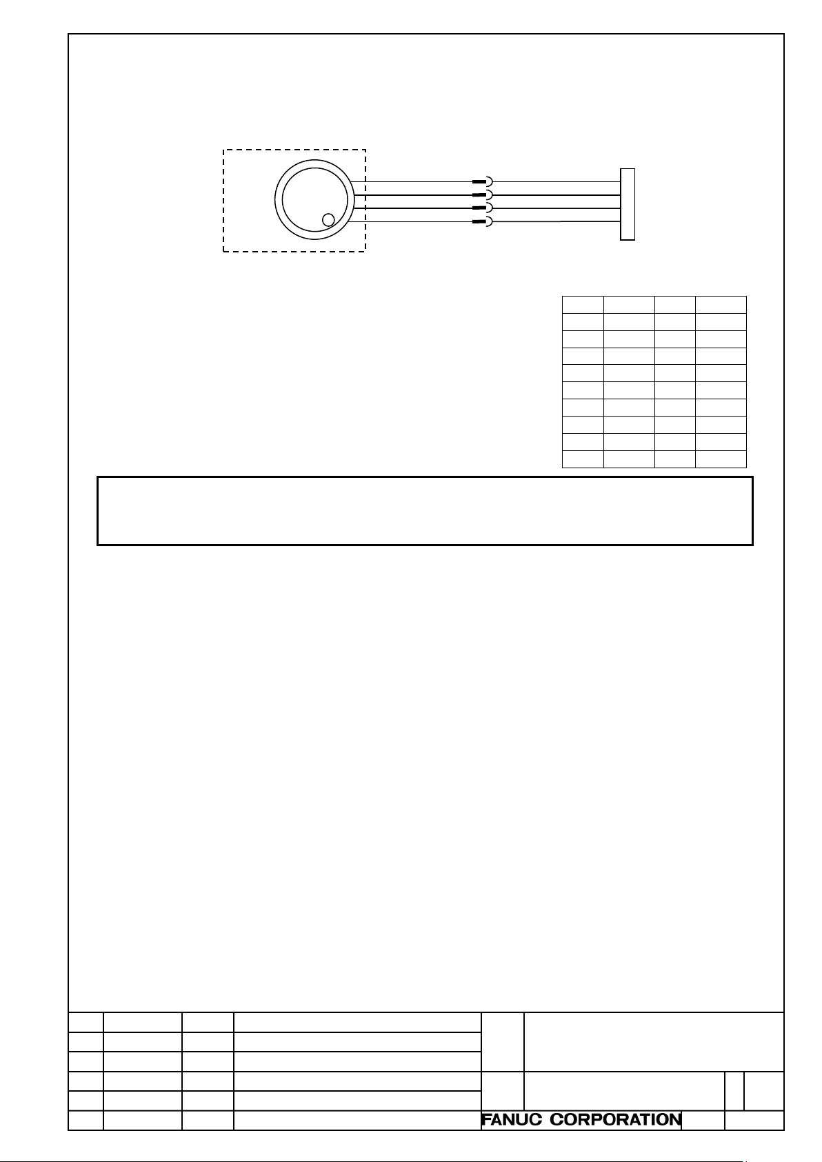
2.7 MANUAL PULSE GENERATOR
This generator outputs pulses for manual handle feed.
Mount the connector for connecting to JA3 of FANUC I/O device.
Connect +5V and 0V to any of the following.
pulse
1
5
10
The connector for connecting to JA3 is lined up at FANUC.
A02B-0120-K303
(including the following connector and case:
Connector: Hirose Electric Co., Ltd. FI40-2015S, type to be soldered,
NOTE
Connect the shield of the cable of the portable manual pulse generator to the ground on the machine side.
・
In the cabinet, separate the signals of the I/O device and the manual pulse generator from the power line when
・
JA3 of FANUC I/O
device
Connection of JA3
Title
Draw.
Portable manual pulse generator
specifications
A-45302E
Page 15
Edit.
Date
Desig.
Description
Page
15 / 18
1 2 3 4
+5V
ESP2
x100
x1
5 6 7 8 9
10
11
12
13
14
15
HB
+24V2
EN1
EN2
LED+
SHIELD
16
17
18
19
20
+24V1
ESPCOM1
Z X
21
22
23
24
ESPCOM2
C
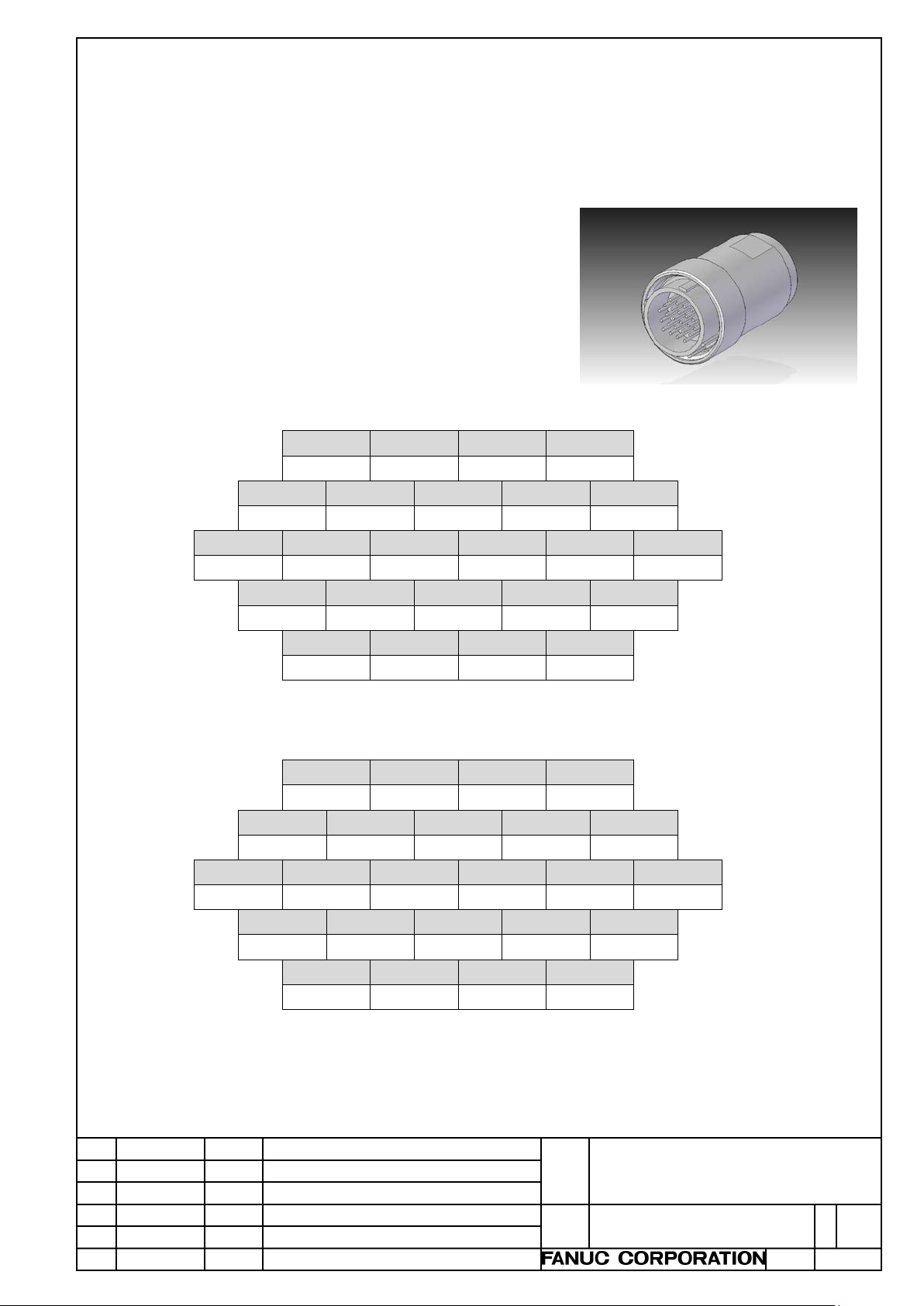
Connection for the T series (axis selection switch: X, Z, and C)
1 2 3 4
+5V
ESP2
x100
x1
5 6 7 8 9
HA
0V, LED-
ESP1
x1000
x10
10
11
12
13
14
15
HB
+24V2
EN1
EN2
LED+
SHIELD
16
17
18
19
20
+24V1
ESPCOM1
Y X 4
21
22
23
24
ESPCOM2
6 Z 5
Connection for the M series (axis selection switch: X, Y, Z, 4, 5, and 6)
2.8 CABLE
The cable is straight or coiled type.
In the straight type, its length can be selec ted from 3.5m and 5.0m.
In the coiled type, its length is only 1. 0m .
Both the straight type and the coiled type are shielded type cable.
2.9 CONNECTOR
Signals which connected to each contacts of the connector
are following.
Signals “0V” and “LED-“ are connected together in “6” of pin
number.
Signal “SHIELD“ means shield of cable, and it is connected in
“15“ of pin number.
HA 0V, LED- ESP1 x1000 x10
Title
Draw.
Portable manual pulse generator
specifications
A-45302E
Page 16
Edit.
Date
Desig.
Description
Page
16 / 18
NOTE
Please put the length of wiring inside machine tool within 1.0 m.
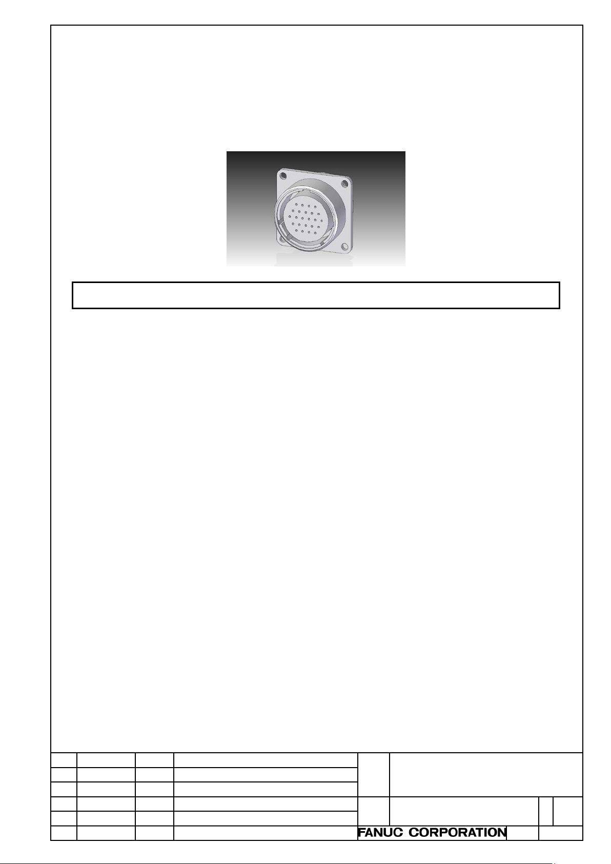
Connector for machine tool side is lined up at FANUC.
Ordering information
Cable connector for machine tool side: A13B-0206-K001 (supplied by FANUC),
or
JR25WR-24S(71) (supplied by Hirose Electric Co., Ltd.)
・
3. MAINTENANCE
A cable connector for machine tool side is mounted by the machine tool builder.
The connec tor treatment differs from one machine tool builder to another and, therefore, FANUC cannot
perform maintenance on the connector treatment inside machine tool.
FANUC m erel y supplies the portable manual pulse generator (including cable with connector).
4. SAFETY
For the safety of the machine, note the followi ng:
・Connect the emergency stop signal of the portable manual puls e generator to the safety circuit of the
entire machine so that the machine can stop in a saf e manner when the emergency stop swit ch of the
portable manual pulse generator is pressed.
・To detect contact failures, the emergency stop switch and the enable switch of the portable manual pulse
generator offer contacts for two syst em s.
Conducts mismatch detection with the signals of the two contacts.
・Prepare a ladder program so that the machine enters the interlock state when the signal of the enable
switch is OFF.
5.
INSTALLATION CONDITION FOR UL RECOGNITION
The portable manual pulse generator complies with UL standard.
Power supply unit for I/O unit to connect this unit mus t have an isol ating device and t he DC 24 Volt output
must be isolated from AC mains supply.
Title
Draw.
Portable manual pulse generator
specifications
A-45302E
Page 17
Edit.
Date
Desig.
Description
Page
17 / 18
deterioration.
CAUTION
manual or of a product altered by the customer.
WARNING
1 When designing, be sure to observe all rules stated in this manual and any related manuals. Otherwise,
failures and malfunctions may occur.
2 If the customer is to use a FANUC product for an appl ication that can pose a significant danger to human
lives and property, he or she is requested to confirm beforehand that the entire system is designed so that
the risk is reported, that the necessary safety is ensured with redundant design, and that the FANUC
product gets electric power and is installed in the entire system appropriately for the intended application.
3 Failures in the portable manual pulse generator, as well as input power abnormalities and communi c ation
failures, can hamper the normal operation of the portable manual pul s e generator. Design the system in
such a way that the machine can operate safely by, for example, providing a safety circuit outside the
portable manual pulse generator so that no accidents will occur even if such failures occur.
Using the dual check safety function makes it possible to detect a single fault related to safety. For details
of the dual check safety function, refer to the dual check safety manual for the CNC unit to use.
4 Coolants containing sulfur or chlorine at a high activation level, oil-free coolants called synthetic type
coolants, and water-soluble coolants at a high alkali level, in particular, can l argely affect the portable
manual pulse generator. Note that such coolants can caus e problems such as those described below.
Coolants containing sulfur or chlorine at a high activation level
・
Some coolants containing sulfur or chlorine are at an extremely high activity level. If such a coolant
adheres to the portable manual pulse generator, it reacts chemically with resin and other materials,
possibly leading to corrosion or deterioration. If it gets in t he portable manual pulse generator, it corrodes
copper, silver, and other metals used as component materials, poss i bly leading to component defects.
Synthetic type coolants having a high permeability
・
Some synthetic type coolants whose lubricating component is, for example, PAG (polyalkylene glycol)
have an extremely high permeability. Even for equipment with a high airtightness, such a coolant can
easily flow into the equipment through, for example, packings. If the coolant gets in the portable manual
pulse generator, it may cause insulation deterioration and component failures.
Water-soluble coolants at a high alkali level
・
Some coolants whose pH is increased using alkanolamine are so strongly alkali that their standard
dilution will reach pH10 or higher. If such a coolant spatters over the surfac e of the portable manual pulse
generator, it reacts chemically with resin and other materials, possi bl y leading to cor rosion or
1 Install the portable manual pulse generator in such a place that neither cutting chips nor coolant will spatter
over it. Otherwise, damage or malfunctions may occur.
2 Use the portable manual pulse generator within the rated voltage and current that are stated in this manual.
Using it with any voltage and cur rent other than the rated ones can cause fire, malfunctions, and failures.
3 We shall not guarantee the function and performance of a product used outside the standards stated in this
FANUC CORPORATION
Oshino-Mura, Yamanashi Pref., 401-0597 JAPA N
Title
Draw.
Portable manual pulse generator
specifications
A-45302E
Page 18
Edit.
Date
Desig.
Description
Page
18 / 18
CAUTION
generator. Using new scaled label sheet, please be sure to put it on the original sheet.
NOTE
the original sheet when you put new label sheet.
Appendix
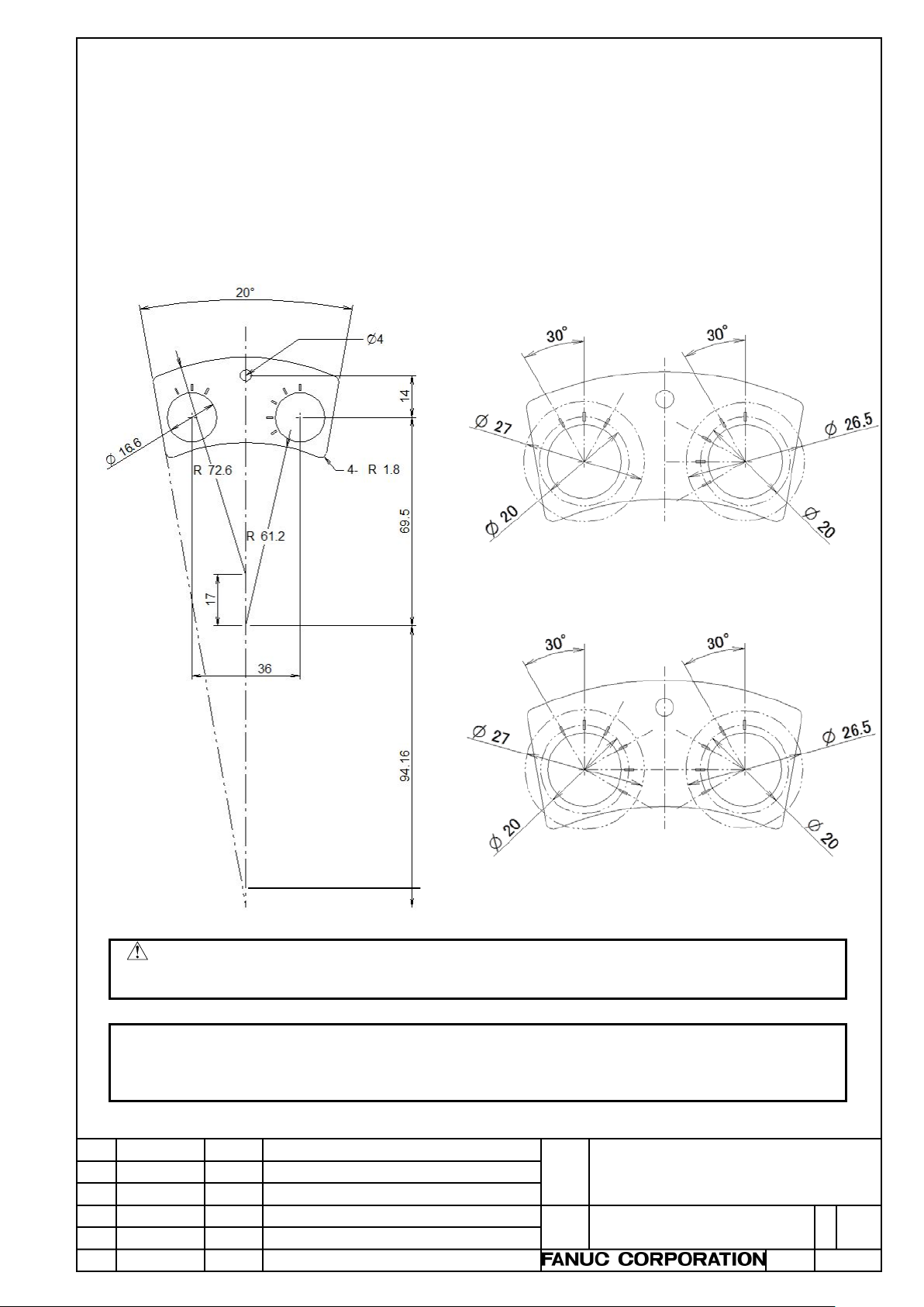
A. DIMENSION OF SCALED LABEL SHEET OF AXIS MAGNIFICATION SELECTION SWITCHES
There are two kinds of the scaled label sheet of axis and magnification selection switches, one is for
T series (X, Z, C/ OFF, x1, x10, x100, x1000) and the other is for M s eries (X, Y, Z, 4, 5, 6/ OFF, x1, x10,
x100, x1000). If you need to change it to other description, please make a new scaled label sheet
according to the machine tool and put the sheet on the original sheet. Dimension of t he scaled sheet is
as follows:
【Dimension of the scale sheet】
・T series (with 3 scale marks for axis selector)
・M series (with 6 scale marks for axis selector)
(Unit: mm)
Do not peel off the original sheet. There is a causal ris k that coolant etc. breaks into the portable manual pulse
・
We do not receive Design to Order at FANUC.
・
The original sheet has fine asperity on its surface. Please s el ec t adhesive with adhesive force enough to put on
・
Title
Draw.
Portable manual pulse generator
specifications
A-45302E
 Loading...